

Mitsubishi PUHY-YMF-B Installation Manual
Air-Conditioners
OUTDOOR UNIT
PUHY-YMF-B
FOR INSTALLER
FÜR INSTALLATEURE
POUR L’INSTALLATEUR
VOOR DE INSTALLATEUR
PER L’INSTALLAT ORE
INSTALLATION MANU AL
For safe and correct use, please read this installation manual thoroughly before installing the air-conditioner unit.
∗ Remote controller (PAR-F25MA) is available as an optional remote controller.
INSTALLATIONSHANDBUCH
Zum sicheren und ordnungsgemäßen Gebrauch der Klimageräte das Installationshandbuch gründlich durchlesen.
∗ Fernbedienung (PAR-F25MA) ist als Zubehör wahlweise erhältlich.
ENGLISH
DEUTSCH
FRANÇAIS
MANUEL D’INSTALLATION
Veuillez lire le manuel d’installation en entier avant d’installer ce climatiseur pour éviter tout accident et vous assurer d’une utilisation
correcte.
∗ La télécommande (PAR-F25MA) est disponible en option.
INSTALLATIEHANDLEIDING
Voor een veilig en juist gebruik moet u deze installatiehandleiding grondig doorlezen voordat u de airconditioner installeert.
∗ De afstandsbedieningseenheid (PAR-F25MA) is verkrijgbaar als een optioneel toe te voegen afstandsbediening.
MANUALE DI INSTALLAZIONE
Per un uso sicuro e corretto, leggere attentamente questo manuale di installazione prima di installare il condizionatore d’aria.
∗ Il comando a distanza (modello PAR-F25MA) disponibile in opzione.
NEDERLANDS
ITALIANO

Contents
1. Safety precautions ...................................................................... 3
1.1. Before installation and electric work.............................. 3
1.2. Before getting installed.................................................. 3
1.3. Before getting installed (moved) - electrical work.......... 4
1.4. Before starting the test run............................................ 4
2. Combination with indoor units..................................................... 5
3. Confirmation of parts attached ................................................... 5
4. Combination with outdoor units .................................................. 6
5. Selection of installation site ........................................................ 6
6. Space required around unit ........................................................ 6
6.1. Individual installation ..................................................... 6
6.2. Collective installation and continuous installation ......... 7
7. Lifting method and weight of product.......................................... 8
8. Installation of unit........................................................................ 8
8.1. Location of anchor bolt.................................................. 8
8.2. Installation ..................................................................... 9
8.3. Connecting direction for refrigerant piping .................. 10
8.4. Noise level................................................................... 10
9. Caution for snow and seasonal wind ........................................ 11
ENGLISH
9.1. Snow and seasonal wind ............................................ 11
9.2. Countermeasure to seasonal wind ............................. 11
10.Refrigerant piping installation .................................................. 12
10.1. Areas of caution .......................................................... 12
10.2. Refrigerant piping system ........................................... 13
10.3. Caution for piping connection/valve operation ............ 15
10.4. How to install branch pipe ........................................... 16
10.5. Airtight test and evacuation......................................... 18
10.6. Thermal insulation of refrigerant piping....................... 19
11.Electrical work ......................................................................... 21
11.1. Caution........................................................................ 21
11.2. Control box and connecting position of wiring............. 22
11.3. Wiring transmission cables ......................................... 23
11.4. Wiring of main power supply and equipment
capacity ....................................................................... 29
12.T est run.................................................................................... 30
12.1. Checking before getting test run ................................. 30
12.2. Test run method .......................................................... 30
12.3. How to cope with test run abnormality ........................ 31
12.4. Coping with remote controller abnormality.................. 33
12.5. The following phenomena do not represent
abnormality (emergency) ............................................ 34
2
1. Safety precautions
1.1. Before installation and electric work
s Before installing the unit, make sure you read all the
“Safety precautions”.
s The “Safety precautions” provide very important points
regarding safety. Make sure you follow them.
Symbols used in the text
Warning:
Describes precautions that should be observed to prevent danger
of injury or death to the user.
Caution:
Describes precautions that should be observed to prevent damage
to the unit.
Symbols used in the illustrations
: Indicates an action that must be avoided.
: Indicates that important instructions must be followed.
: Indicates a part which must be grounded.
: Indicates that caution should be taken with rotating parts. (This
symbol is displayed on the main unit label.) <Color: Yellow>
: Indicates that the main switch must be turned off before servicing.
(This symbol is displayed on the main unit label.) <Color: Blue>
: Beware of electric shock (This symbol is displayed on the main
unit label.) <Color: Yellow>
: Beware of hot surface (This symbol is displayed on the main unit
label.) <Color: Yellow>
: Please pay attention to electric shock fully because this is
ELV
not Safety Extra Low-Voltage (SELV) circuit.
And at servicing, please shut down the power supply for both
of Indoor Unit and Outdoor Unit.
Warning:
Carefully read the labels affixed to the main unit.
Warning:
• Ask the dealer or an authorized technician to install the air conditioner.
- Improper installation by the user ma y result in water leakage, elec-
tric shock, or fire.
• Install the air unit at a place that can withstand its weight.
- Inadequate strength may cause the unit to fall down, resulting in
injuries.
• Use the specified cables for wiring. Make the connections securely so that the outside force of the cable is not applied to the
terminals.
- Inadequate connection and fastening may gener ate heat and cause
a fire.
• Prepare for typhoons and other strong winds and earthquakes
and install the unit at the specified place.
- Improper installation may cause the unit to topple and result in in-
jury.
• Always use an air cleaner, humidifier, electric heater, and other
accessories specified by Mitsubishi Electric.
- Ask an authorized technician to install the accessories. Improper
installation by the user may result in water leakage, electric shock,
or fire.
• Never repair the unit. If the air conditioner must be repaired,
consult the dealer.
- If the unit is repaired improperly, water leakage, electric shock, or
fire may result.
• Do not touch the heat exchanger fins.
- Improper handling may result in injury.
• If refrigerant gas leaks during installation work, ventilate the
room.
- If the refrigerant gas comes into contact with a flame, poisonous
gases will be released.
• Install the air conditioner according to this Installation Manual.
- If the unit is installed improperly, water leakage, electric shock, or
fire may result.
• Have all electric work done by a licensed electrician according
to “Electric Facility Engineering Standard” and “Interior Wire
Regulations”and the instructions given in this manual and always use a special circuit.
- If the power source capacity is inadequate or electric work is per-
formed improperly, electric shock and fire may result.
• Securely install the cover of control box and the panel.
- If the cover and panel are not installed properly, dust or water ma y
enter the outdoor unit and fire or electric shock may result.
• When installing and moving the air conditioner to another site,
do not charge the it with a refrigerant different from the refrigerant (R22) specified on the unit.
- If a different refrigerant or air is mixed with the original refrigerant,
the refrigerant cycle may malfunction and the unit may be damaged.
• If the air conditioner is installed in a small room, measures must
be taken to prevent the refrigerant concentration from exceeding the safety limit even if the refrigerant should leak.
- Consult the dealer regarding the appropriate measures to prevent
the safety limit from being exceeded. Should the refrigerant leak
and cause the safety limit to be exceeded, hazards due to lack of
oxygen in the room could result.
• When moving and reinstalling the air conditioner, consult the
dealer or an authorized technician.
- If the air conditioner is installed improperly, water leakage, electric
shock, or fire may result.
• After completing installation work, make sure that refrigerant
gas is not leaking.
- If the refrigerant gas leaks and is exposed to a fan heater, stove,
oven, or other heat source, it may generate noxious gases.
• Do not reconstruct or change the settings of the protection devices.
- If the pressure switch, thermal switch, or other protection de vice is
shorted and operated forcibly, or parts other than those specified
by Mitsubishi Electric are used, fire or explosion may result.
• To dispose of this product, consult your dealer.
• The installer and system specialist shall secure safety against
leakage according to local regulation or standards.
- Following standards may be applicable if local regulation are not
available.
• Pay a special attention to the place, such as a basement, etc.
where refrigeration gas can stay, since refrigeration is heavier
than the air.
1.2. Before getting installed
Caution:
• Do not install the unit where combustible gas may leak.
- If the gas leaks and accumulates around the unit, an explosion
may result.
• Do not use the air conditioner where food, pets, plants, precision instruments, or artwork are kept.
- The quality of the food, etc. may deteriorate.
• Do not use the air conditioner in special environments.
- Oil, steam, sulfuric smoke, etc. can significantly reduce the per-
formance of the air conditioner or damage its parts.
• When installing the unit in a hospital, communication station,
or similar place, provide sufficient protection against noise.
- The inverter equipment, private power generator, high-frequency
medical equipment, or radio communication equipment may cause
the air conditioner to operate erroneously , or f ail to operate. On the
other hand, the air conditioner may affect such equipment by creating noise that disturbs medical treatment or image broadcasting.
• Do not install the unit on a structure that may cause leakage.
- When the room humidity exceeds 80% or when the drain pipe is
clogged, condensation may drip from the indoor unit. Perform collective drainage work together with the outdoor unit, as required.
3
ENGLISH

1.3. Before getting installed (moved) electrical work
Caution:
• Ground the unit.
- Do not connect the ground wire to gas or water pipes, lightning
rods, or telephone ground lines. Improper grounding may result in
electric shock.
• The reverse phase of L lines (L
cord: 4103), but the reverse phase of L lines and N line can be
not be detected.
- The some electric parts should be dameged when power is sup-
plied under the miss wiring.
• Install the power cable so that tension is not applied to the cable.
- T ension ma y cause the cable to break and generate heat and cause
a fire.
• Install an leak circuit breaker, as required.
- If an leak circuit breaker is not installed, electric shock may result.
• Use power line cables of sufficient current carrying capacity
and rating.
- Cables that are too small may leak, generate heat, and cause a
fire.
• Use only a circuit breaker and fuse of the specified capacity.
- A fuse or circuit breaker of a larger capacity or a steel or copper
wire may result in a general unit failure or fire.
• Do not wash the air conditioner units.
ENGLISH
- Washing them may cause an electric shock.
• Be careful that the installation base is not damaged by long use.
- If the damage is left uncorrected, the unit may fall and cause per-
sonal injury or property damage.
• Install the drain piping according to this Installation Manual to
ensure proper drainage. Wrap thermal insulation around the
pipes to prevent condensation.
- Improper drain piping may cause water leakage and damage to
furniture and other possessions.
• Be very careful about product transportation.
- Only one person should not carry the product if it weighs more than
20 kg.
- Some products use PP bands for packaging. Do not use any PP
bands for a means of transportation. It is dangerous.
- Do not touch the heat exchanger fins. Doing so may cut your fin-
gers.
- When transporting the outdoor unit, suspend it at the specified po-
sitions on the unit base. Also support the outdoor unit at four points
so that it cannot slip sideways.
• Safely dispose of the packing materials.
- Pac king materials, such as nails and other metal or wooden parts,
may cause stabs or other injuries.
- Tear apart and throw away plastic packaging bags so that children
will not play with them. If children pla y with a plastic bag which w as
not torn apart, they face the risk of suffocation.
1, L2, L3) can be detected (Error
1.4. Before starting the test run
Caution:
• Turn on the power at least 12 hours before starting operation.
- Starting operation immediately after turning on the main power
switch can result in severe damage to internal parts. Keep the pow er
switch turned on during the operational season.
• Do not touch the switches with wet fingers.
- Touching a switch with wet fingers can cause electric shock.
• Do not touch the refrigerant pipes during and immediately after
operation.
- During and immediately after operation, the refrigerant pipes are
may be hot and may be cold, depending on the condition of the
refrigerant flowing through the refrigerant piping, compressor, and
other refrigerant cycle parts. Your hands may suffer burns or frostbite if you touch the refrigerant pipes.
• Do not operate the air conditioner with the panels and guards
removed.
- Rotating, hot, or high-voltage parts can cause injuries.
• Do not turn off the power immediately after stopping operation.
- Alwa ys wait at least five minutes before turning off the power. Oth-
erwise, water leakage and trouble may occur.
4
2. Combination with indoor units
The indoor units connectable to this unit are shown below.
Outdoor unit model
name
Note:
1. The total capacity of connected indoor unit models represents the total sum of the figures expressed in the indoor model name.
2. Combinations in which the total capacity of the connected indoor units exceeds the capacity of the outdoor unit will reduce the capacity
of each indoor unit below the rated capacity during simultaneous operation. Therefore, if circumstances allows, combine indoor units
within the capacity of the outdoor unit.
3. A transmission booster (RP) is required when the number of connected indoor unit models in a cooling system exceeds the number of
models specified in the chart below.
* The maximum number of units that can be controlled is determined by the indoor unit model, the type of remote controller and their
capabilities.
(*1)
Capability of the
connected indoor units
*1 If even one unit that is higher than 200 exists in the cooling system, the maximum capacity will be “200 or higher”.
Total capacity of
connected indoor unit
models
200 to 520PUHY-400
250 to 650PUHY-500
Number of connected indoor units that can be
connected without a RP
200 or lower
200 or higher
Quantity of connectable
indoor unit
PMFY-P25 · 32 · 40 · 63 VBM
PLFY- P32· 40 · 50 · 63 · 80 · 100 · 125 VKM
PLFY- P25· 32 · 40 · 50 · 63 · 80 · 100 · 125 VLMD
PEFY-P25 · 32 VML
PEFY-P40 · 50 · 63 · 71 · 80 · 100 · 125 · 140 · 200 · 250 VMH
2 to 20
Remote controller type
The number of indoor units and the total number of remote controllers is displayed within the parenthesis ( ).
PCFY-P40 · 63 · 100 · 125 VGM
PKFY-P25 VAM
PKFY-P32 · 40 · 50 VGM
PFFY- P25 · 32 · 40 · 50 · 63 VLEM
PFFY- P25 · 32 · 40 · 50 · 63 VLRM
PDFY-P25 · 32 · 40 · 50 · 63 · 71 · 80 · 100 · 125 VM
Model name of connectable indoor unit
Remote controller PAR-F 25MA
Prior to Ver. E After Ver. F
16 (32) 20 (40)
16 (32) 16 (32)
ENGLISH
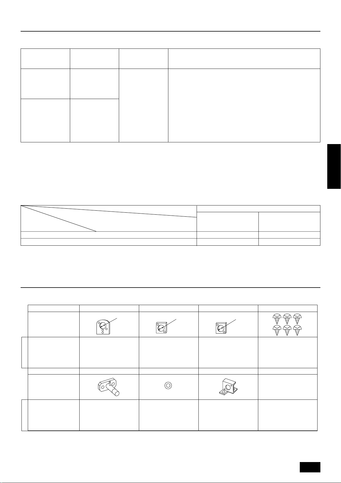
3. Confirmation of parts attached
This outdoor unit is attached with the parts below. Please check the quantity for each item.
Name 1 Conduit mounting plate 2 Conduit mounting plate 3 Conduit mounting plate 4 Tapping screw M4 × 10
Shape
PUHY-400
PUHY-500
Model name
Name 5 Connecting pipe 6 Packing 7 Wire mounting plate
Shape
PUHY-400
PUHY-500
Model name
ø62
1116
inside ø29, outside ø39
111
ø53
ø46
*5 Connecting pipe is fixed with the unit.
5
4. Combination with outdoor units
A Super Y (PUHY-600/650/700/750YSMF-B) is produced when a Constant Capacity Unit (PUHN-200/250YMF-B) is combined with this unit (PUHY400/500YMF-B).
Refer to the installation manual that comes with the Constant Capacity Unit when this unit is used as a Super Y.
Super Y
PUHY-600YSMF-B
PUHY-650YSMF-B
PUHY-700YSMF-B
PUHY-750YSMF-B
Variable capacity unit
PUHY-400YMF-B
PUHY-500YMF-B
5. Selection of installation site
Select space for installing outdoor unit, which will meet the following
conditions:
• no direct thermal radiation from other heat sources
• no possibility of annoying neighbors by noise from unit
• no exposition to strong wind
• with strength which bears weight of unit
• note that drain flows out of unit when heating
• with space for air passage and service work shown below
ENGLISH
Because of the possibility of fire, do not install unit to the space where
generation, inflow, stagnation, and leak of combustible gas is expected.
• Avoid unit installation in a place where acidic solution and spra y (sulfur)
are often used.
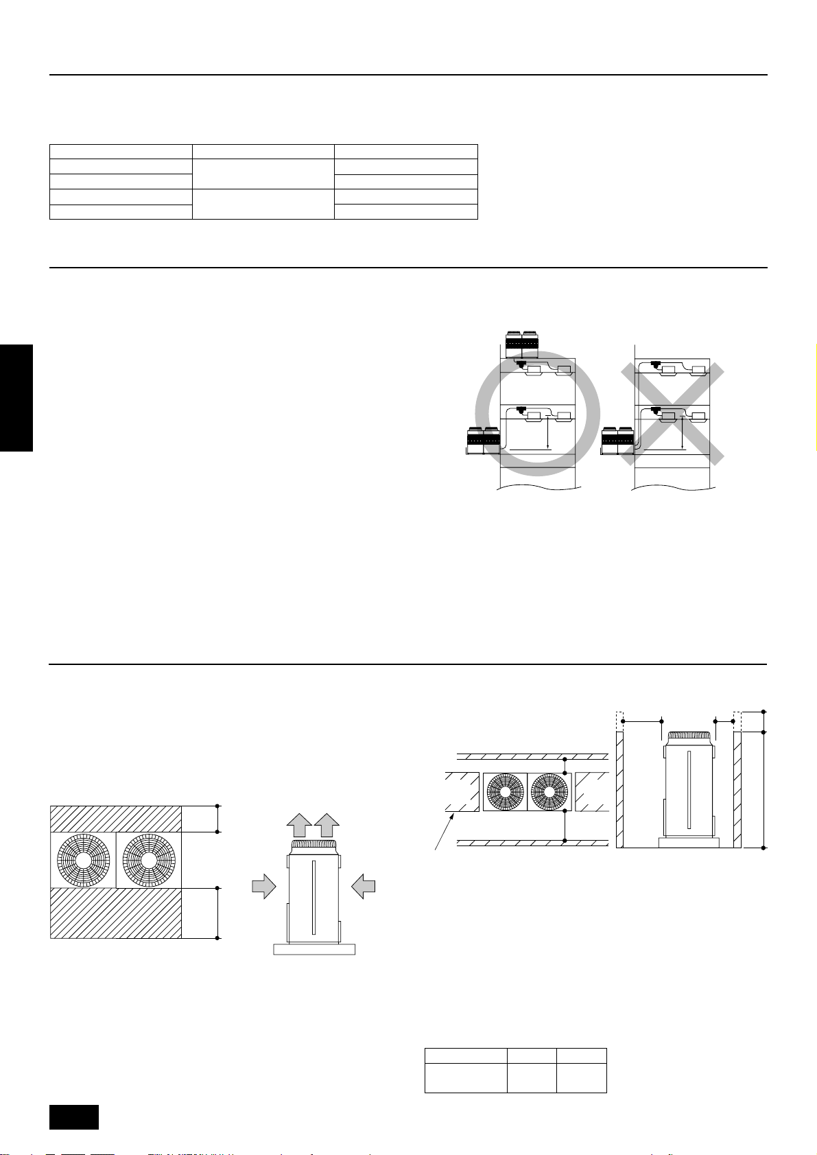
• When having cooling operation at an outside air temperature of below 10°C, in order to obtain steady operation of unit, select an installation site not exposed directly to rain and snow, or install air outlet
and inlet ducts. (Refer to Page 11.) Install the outdoor unit at the
same position on the same floor, or above, the indoor unit. (See the
figure at the right.)
• Do not use unit in any special environment where oil, steam and
sulfuric gas exist.
Constant capacity unit
PUHN-200YMF-B
PUHN-250YMF-B
PUHN-200YMF-B
PUHN-250YMF-B
Installation restriction on outdoor unit when cooling operation is performed
when the outdoor air temperature is 10°C or lower
A
(Same floor as indoor unit, or floor above)
A 4 m or less
6. Space required around unit
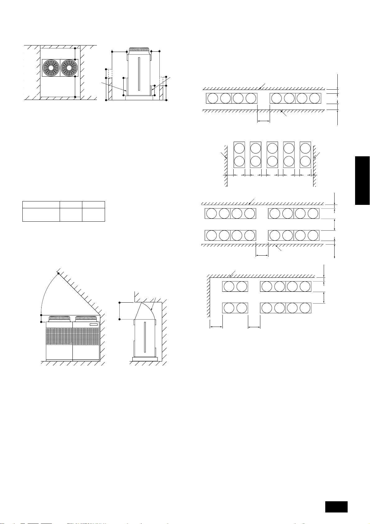
6.1. Individual installation
Basic space required
A space of at least 250 mm is necessary at the back for inlet air. Taking
servicing, etc. from the rear into account, a space of about 450 mm
should be provided, the same as at the front.
D
A
FE
B
C
<Top view> <Side view>
A 250 mm or more
B 450 mm or more
C Front (outside of machine room)
D Top discharge (open in principle)
E Front inlet (open in principle)
F Rear inlet (open in principle)
When inlet air enters from right and left sides of unit
A
B
B
C
C
A
D
<Side view>
A L
1 or more
B L
2 or more
C Front
D No restrictions on wall height (left and right)
Note:
• Wall heights (H) of the front and the back sides shall be within
overall height of unit.
• When the total height is exceeded, add the “h” dimension of the
figure above to L1 and L2 in the table above.
Model L1 L2
PUHY-400
PUHY-500
450 250
Hh
6
When unit is surrounded by walls
A
B
B
C
E
A
D
Hh
650
325
h
H
C
<Side view>
A L
1 or more
2 or more
B L
C Front
D Front panel
E Rear panel
Note:
• Wall heights (H) of the front and the back sides shall be within
height of front panel and rear panel.
• If the panel height is exceeded, add the “h” dimension of the
figure above to L1 and L2 in the table above.
Model L1 L2
PUHY-400
PUHY-500
450 250
6.2. Collective installation and continuous installation
Space required for collective installation and continuous installation:
When installing several units, leave the space between each block as
shown below considering passage for air and people.
B
*E
*F
E
GCC
ENGLISH
A
B
AA
CC
D
B
A
B
CCCCC
*FF F F F*E
A
B
A
Example: When h is 100
The L1 dimension becomes 450 + 100 = 550 mm.
When there is an obstruction above the unit
A
D
B
When there is little space
A 45° or more
B 300 mm or more
C Front
D 1000 mm or more
E Air outlet guide (Procured at the site)
F Rear
E
CF
up to an obstruction
E
E
B
D
B
A
C
DD
A
A (Must be open)
B Wall height (H)
C Front
D 1000 mm or more
E 250 mm or more
F 450 mm or more
G 900 mm or more
Note:
• Open in the two directions.
• In case wall height (H) exceeds overall height of unit, add “h”
dimension (h = wall height <H> – overall height of unit) to *
marked dimension.
• If there is a wall at both the front and the rear of the unit, install
up to three units consecutively in the side direction and provide
a space of 1000 mm or more as inlet space/passage space for
each three units.
CG
7
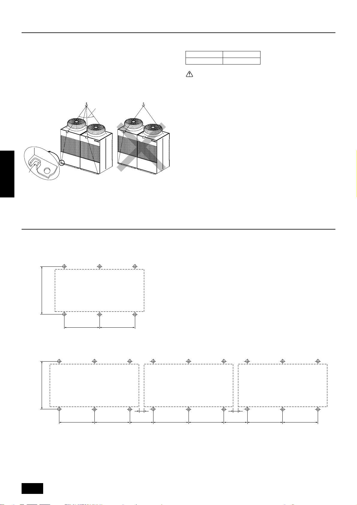
7. Lifting method and weight of product
• When carrying the unit suspended, pass the ropes under the unit
and use the two suspension points each at the front and rear.
• Always lift the unit with ropes attached at four points so that impact is
not applied to the unit.
• Attach the ropes to the unit at an angle of 40° or less.
• Use two ropes at least 8 m long.
A
B
Dangerous!
ENGLISH
A 40° or less
B Rope suspension part
Weight of product:
PUHY-400 PUHY-500
432 kg 472 kg
Caution:
Be very careful to carry product.
- Do not have only one person to carry product if it is more than 20 kg.
- PP bands are used to pack some products. Do not use them as a
mean for transportation because they are dangerous.
- Do not touch heat exchanger fins with y our bare hands. Otherwise you
may get a cut in your hands.
- Tear plastic packaging bag and scrap it so that children cannot play
with it. Otherwise plastic pac kaging bag may suffocate children to death.
- When carrying in outdoor unit, be sure to support it at four points. Carrying in and lifting with 3-point support may make outdoor unit unstable, resulting in a fall of it.
8. Installation of unit
8.1. Location of anchor bolt
• Individual installation
880±5
780±2
• Example of collective installation
880±5
780±2
A
A (Service side)
8
780±2
780±2 440 440780±2 780±2 780±2 780±2
10 10
For collective installation, provide a 10 mm gap between units.
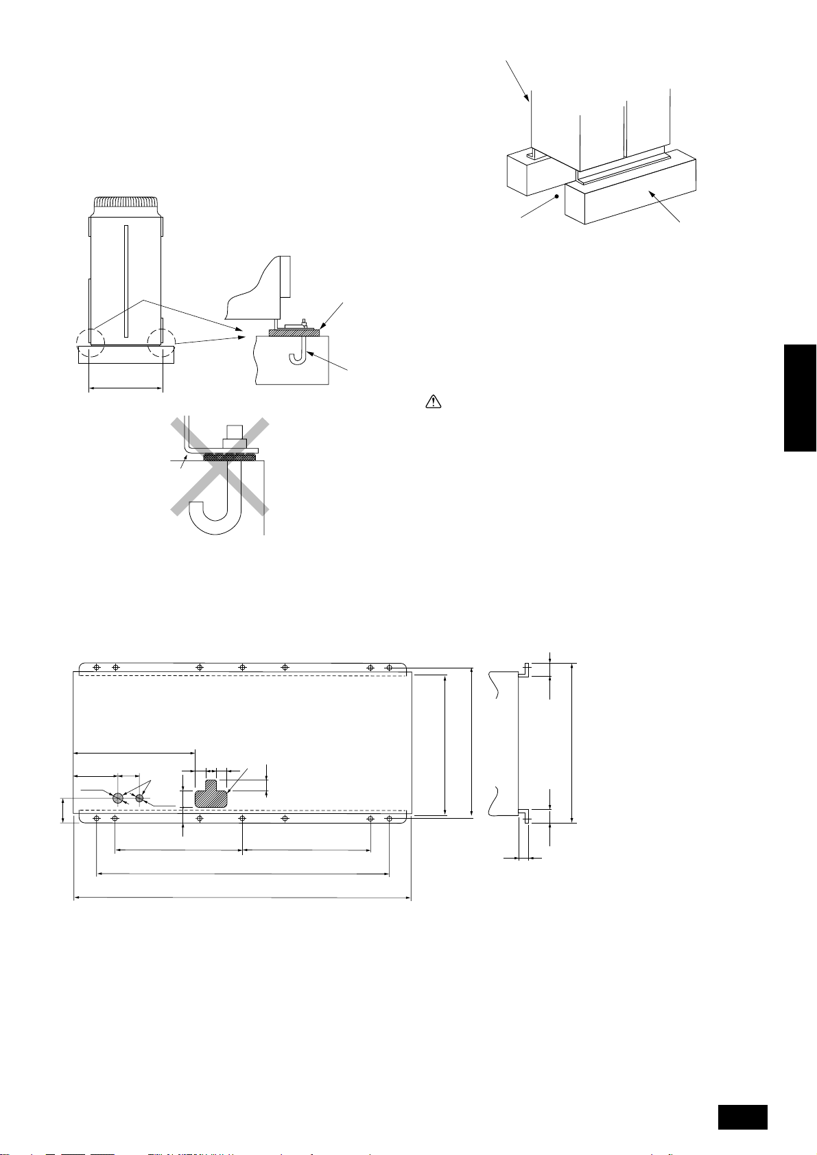
8.2. Installation
• Fix unit tightly with bolts as shown below so that unit will not fall down
due to earthquake or gust.
• Use concrete or angle for foundation of unit.
• Vibration may be transmitted to the installation section and noise
and vibration may be generated from the floor and walls, depending
on the installation conditions. Therefore, provide ample
vibrationproofing (cushion pads, cushion frame, etc.).
D
A
880±5
B
C
Down piping and down wiring precautions
When down piping and down wiring are performed, be sure that foundation and base work does not block the base through holes. When down
piping is performed, make the foundation at least 100 mm high so that
the piping can pass under the bottom of the unit.
E
A Be sure that the corners are fir mly seated. If the corners are not firmly
seated, the installation feet may be bent.
B M10 anchor bolt procured at the site
C Corner is not seated.
D Unit
(Provide ample vibrationproofing between the unit and the foundation by
using cushion pads, cushion frame, etc.)
E Piping and wiring space (Bottom piping, bottom wiring)
F Concrete foundation
F
Warning:
• Be sure to install unit in a place strong enough to withstand its
weight.
Any lack of strength may cause unit to fall down, resulting in a
personal injury.
• Have installation work in order to protect against a str ong wind
and earthquake.
Any installation deficiency may cause unit to fall down, resulting in a personal injury.
When building the foundation, give full attention to the floor strength,
drain water disposal <during operation, drain water flows out of the unit>,
and piping and wiring routes.
ENGLISH
694
230
150
Ø62
111
A Bottom piping through hole
B (bolt hole)
C (bolt hole for old models)
D (unit width)
E (unit depth)
F Bottom wiring through hole
F
Ø27
780
80 82 78
90
73
B
1760
1990
5656
840 E
A
80
780
B
C
D
880 B
15
910
9
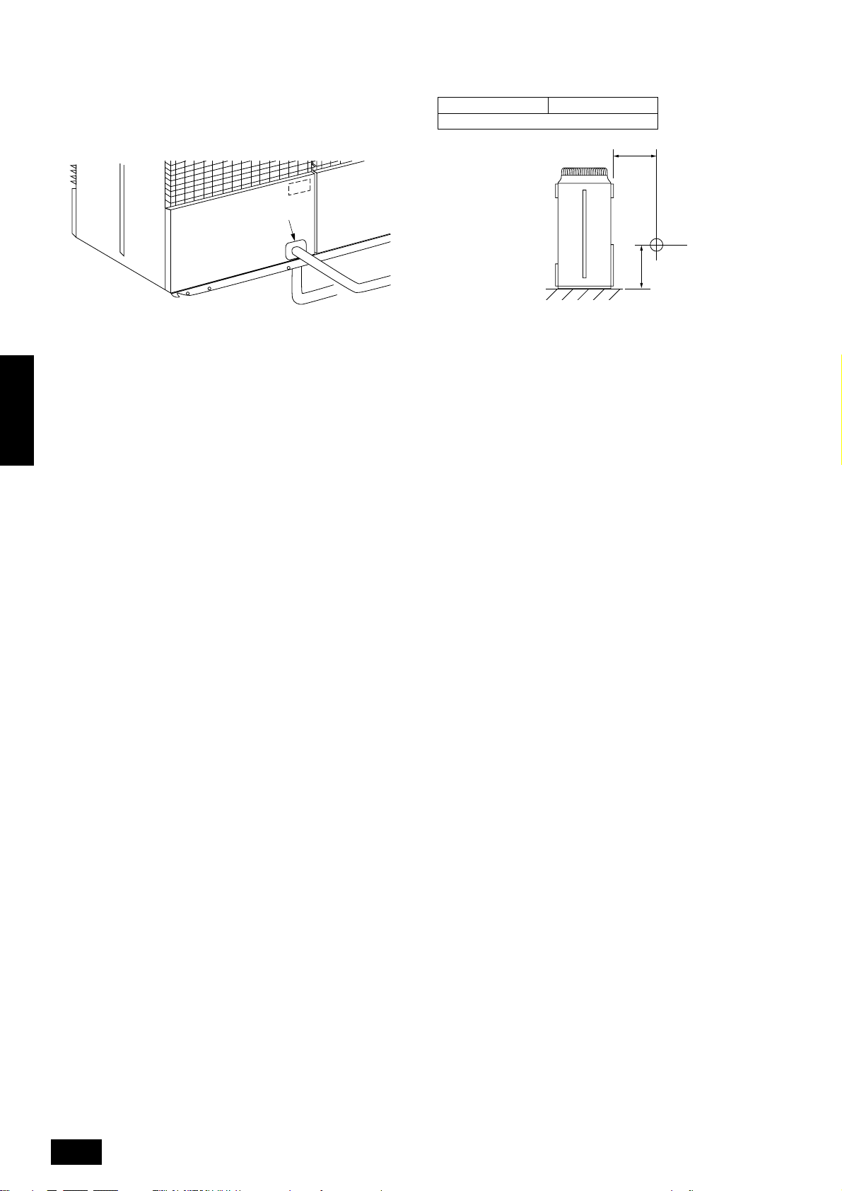
8.3. Connecting direction for refrigerant
piping
Two connecting directions are available for refrigerant piping of the outdoor unit, bottom piping and front piping, as shown below:
8.4. Noise level
(50/60Hz)
PUHY-400 PUHY-500
60/61 dB(A)
1m
A
B
A Knock-out hole
B Bottom piping
C Front piping
Note:
In the case of bottom piping, build a 100 mm or higher foundation
so that piping will go through the bottom of the unit.
ENGLISH
C
A
1m
B
A Front
B Measuring point
Measuring location: a room free from echoes and reverberations
10

9. Caution for snow and seasonal wind
In cold and/or snowy areas, sufficient countermeasures to wind and
snow damages should be taken for operating unit in normal and good
condition in winter time. Even in the other areas, full consideration is
required for installation of unit in order to prevent abnormal operations
caused by seasonal wind or snow. When rain and snow directly fall
on unit in the case of air-conditioning operations in 10 or less degrees centigrade outdoor air, mount inlet and outlet ducts on unit
for assuring stable operations.
9.1. Snow and seasonal wind
■ Prevention of wind and snow damages in cold or snowy areas:
Refer to the figure of snow hood shown below:
• Snow hood
1093
A
Note:
1. Height of frame base for snow damage prevention (H) shall be
twice as high as expected snowfall. Width of frame base shall
not exceed that of the unit. The frame base shall be made of
angle steel, etc., and designed so that sno w and wind slip through
the structure. (If frame base is too wide, snow will be accumulated on it.)
2. Install unit so that seasonal wind will not directly lash against
openings of inlet and outlet ducts.
3. Build frame base at customer referring to this figure.
Material : Galvanized steel plate 1.2T
Painting: Overall painting with polyester powder
Color : Munsell 5Y8/1 (same as that of unit)
4. When the unit is used in a cold region and the heating operation
is continuously performed for a long time when the outside air
temperature is below freezing, install a heater to the unit base
or take other appropriate measures to prevent water from freezing on the base.
1888
ENGLISH
1145
B
500(840)500
(670) 821 903
(1990)
B
H
A Outlet
B Inlet
9.2. Countermeasure to seasonal wind
Referring to the figure shown below, take appropriate measures which
will suit the actual situation of the place for installation.
AA
A Seasonal wind
11
 Loading...