

Mitsubishi Electric PUHY-RP-Y(S)JM-B, PURY-RP-YJM-B Service Manual

DATA BOOK
AIR CONDITIONERS
MODEL
PUHY-RP-Y(S)JM-B
PURY-RP-YJM-B

REPLACE MULTI
1.OUTDOOR UNIT
Y SERIES ................................................................................................................. 1
R2 SERIES............................................................................................................. 61
2.CAPACITY TABLES (Indoor unit)............................................................ 87
3.SYSTEM DESIGN
Y SERIES ............................................................................................................. 189
R2 SERIES........................................................................................................... 241
4.CONTROLLER ................................................................................................. 285


1
Y SERIES
OUTDOOR UNITS
OUTDOOR UNITS
I.Y SERIES
1. SPECIFICATIONS........................................................................................................................................... 2
2. EXTERNAL DIMENSIONS .............................................................................................................................. 15
3. CENTER OF GRAVITY ................................................................................................................................... 19
4. ELECTRICAL WIRING DIAGRAMS................................................................................................................ 20
5. SOUND LEVELS ............................................................................................................................................. 21
6. CAPACITY TABLES........................................................................................................................................ 25
6-1. Correction by temperature....................................................................................................................... 25
6-2. Correction by total indoor......................................................................................................................... 39
6-3. Correction by refrigerant piping length..................................................................................................... 43
6-4. Correction at frost and defrost ................................................................................................................. 46
6-5. Operation temperature range .................................................................................................................. 47
7. OPTIONAL PARTS.......................................................................................................................................... 48
7-1. OUTDOOR TWINNING KIT..................................................................................................................... 48
8. UNIT SELECTION........................................................................................................................................... 49
8-1. Indoor and outdoor unit selection ............................................................................................................ 49
8-2. Calculation samples................................................................................................................................. 51
8-3. Pipe diameter correction factor ................................................................................................................ 54
1. SPECIFICATIONS
OUTDOOR UNITS 2
I.Y SERIES1. SPECIFICATIONS
Model PUHY-RP200YJM-B(-BS) PUHY-RP250YJM-B(-BS)
Power source 3-phase 4-wire 380-400-415V 50/60Hz 3-phase 4-wire 380-400-415V 50/60Hz
Cooling capacity *1 kW 22.4 28.0
(Nominal) *1 kcal / h 19,300 24,100
*1 BTU / h 76,400 95,500
Power input kW 5.68 7.62
Current input A 9.5-9.1-8 .7 12.8-12.2-11.7
COP kW / kW 3.94 3.67
Temp. range of Indoor W.B. 15.0~24.0°C(59~75°F) 15.0~24.0°C(59~75°F)
cooling Outdoor D.B. -5.0~43.0°C(23~109°F) -5.0~43.0°C(23~109°F)
Heating capacity *2 kW 25.0 31.5
(Nominal) *2 kcal / h 21,500 27,100
*2 BTU / h 85,300 107,500
Power input kW 5.69 7.22
Current input A 9.6-9.1-8 .7 12.1-11.5-11.1
COP kW / kW 4.39 4.36
Temp. range of Indoor D.B. 15.0~27.0°C(59~81°F) 15.0~27.0°C(59~81°F)
heating Outdoor W.B. -20.0~15.5°C(-4~60°F) -20.0~15.5°C(-4~60°F)
Indoor unit Total capacity 50~130 % of outdoor unit capacity 50~130 % of outdoor unit capacity
connectable Model / Quantity P15~P250 / 1~17 P15~P250 / 1~21
Sound pressure level (measured in anechoic room) dB <A> 56 57
Refrigerant Liquid pipe mm (in.) 12.7(1/2) Brazed 12.7(1/2) Brazed
piping diameter Gas pipe mm (in.) 28.58(1-1/8) Brazed 28.58(1-1/8) Brazed
FAN Type x Quantity Propeller fan x 1 Propeller fan x 1
Air flow rate m3 / min 185 185
L/s 3,083 3,083
cfm 6,532 6,532
Control, Driving mechanism Inverter-control, Direct-driven by motor Inverter-control, Direct-driven by motor
Motor output kW 0.92 x 1 0.92 x 1
*3 External static press. 0 Pa (0 mmH2O) 0 Pa (0 mmH2O)
Compressor Type x Quantity Inverter scroll hermetic compressor Inverter scroll hermetic compressor
Manufacture AC&R Works, MITSUBISHI ELECTRIC CORPORATION AC&R Works, MITSUBISHI ELECTRIC CORPORATION
Starting method Inverter Inverter
Motor output kW 4.8 6.8
Case heater kW 0.035(240 V) 0.045(240 V)
Lubricant MEL32 MEL32
External finish
Pre-coated galvanized steel sheets (+powder coating for -BS
type)
Pre-coated galvanized steel sheets (+powder coating for -BS
type)
<MUNSELL 5Y 8/1 or similar> <MUNSELL 5Y 8 /1 or similar>
External dimension HxWxD mm 1,710(1,650 without legs) x 920 x 760 1,710(1,650 without legs) x 920 x 760
in. 67-3/8(65 without legs) x 36-1/4 x 29-15/16 67-3/8(65 without legs) x 36-1/4 x 29-15/16
Protection devices High pressure protection
High pressure sensor, High pressure switch at 4.15,3.3MPa
(601,479 psi)
High pressure sensor, High pressure switch at 4.15,3.3MPa
(601,479 psi)
Inverter circuit (COMP. / FAN) Over-heat protection, Over-current protection Over-heat protection, Over-current protection
Compressor Over-heat protection Over-heat protection
Fan motor Thermal switch Thermal switch
Refrigerant Type x original charge R410A x 6.5kg (15lbs) R410A x 9.0kg (20lbs)
Control LEV and HIC circuit LEV and HIC circuit
Net weight kg (lbs) 230(508) 255(563)
Heat exchanger Salt-resistant cross fin & copper tube Salt-resistant cross fin & copper tube
HIC circuit (HIC: Heat Inter-Changer) Copper pipe,tube-in-tube structure Copper pipe,tube-in-tube structure
Defrosting method Auto-defrost mode (Reversed refrigerant cycle) Auto-defrost mode (Reversed refrigerant cycle)
Drawing External KD94G725 KD94G725
Wiring KE94C490 KE9 4C490
Standard attachment Document Installation Manual Installation Manual
Accessory Refrigerant conn. pipe Refrigerant conn. pipe
Optional parts
Header: CMY-Y104/108/1010-G Header: CMY-Y104/108/1010-G
Remarks ●.Details on foundation work, duct work, insulation work, electrical wiring, power source switch, and other items shall be re-
ferred to the Installation Manual.
●.Due to continuing improvement, above specifications may be subject to change without notice.
●.Our company is unable to guarantee reliability of pre-existing pipes and pre-existing cables.
Notes : Unit converter
1.Nominal cooling conditions (subj ect to JIS B8615-1)
Indoor: 27°CDB/19°CWB (81°FDB/66°FWB), Outdoor: 35°CDB (95°FDB)
Pipe length: 7.5 m (24-9/16 ft.), Level difference: 0 m (0 ft.)
2.Nominal heating conditions (subject to JIS B8615-1)
Indoor: 20°CDB (68°FDB), Outdoor: 7°CDB/6°CWB (45°FDB/43°FWB)
Pipe length: 7.5 m (24-9/16 ft.), Level difference: 0 m (0 ft.)
3.External static pressure option is available (30 Pa, 60 Pa/3.1 mmH2O, 6.1 mmH2O).
kcal =kW x 860
BTU/h =kW x 3,412
cfm =m3/min x 35.31
lbs =kg / 0.4536
*The specification data is
subject to rounding variation.
3
1. SPECIFICATIONS
OUTDOOR UNITS
Model PUHY-RP300YJM-B(-BS) PUHY-RP350YJM-B(-BS)
Power source 3-phase 4-wire 380-400-415V 50/60Hz 3-phase 4-wire 380-400-415V 50/60Hz
Cooling capacity *1 kW 33.5 40.0
(Nominal) *1 kcal / h 28,800 34,400
*1 BTU / h 114,300 136,500
Power input kW 8.98 11.79
Current input A 15.1-14.4-13.8 19.9-18.9-18.2
COP kW / kW 3.73 3.39
Temp. range of Indoor W.B. 15.0~24.0°C(59~75°F) 15.0~24.0°C(59~75°F)
cooling Outdoor D.B. -5.0~43.0°C(23~109°F) -5.0~43.0°C(23~109°F)
Heating capacity *2 kW 37.5 45.0
(Nominal) *2 kcal / h 32,300 38,700
*2 BTU / h 128,000 153,500
Power input kW 9.42 12.60
Current input A 15.9-15.1-14.5 21.2-20.2-19.4
COP kW / kW 3.98 3.57
Temp. range of Indoor D.B. 15.0~27.0°C(59~81°F) 15.0~27.0°C(59~81°F)
heating Outdoor W.B. -20.0~15.5°C(-4~60°F) -20.0~15.5°C(-4~60°F)
Indoor unit Total capacity 50~130 % of outdoor unit capacity 50~130 % of outdoor unit capacity
connectable Model / Quantity P15~P250 / 1~26 P15~P250 / 1~30
Sound pressure level (measured in anechoic room) dB <A> 59 60
Refrigerant Liquid pipe mm (in.) 12.7(1/2) Brazed 15.88(5/8) Brazed
piping diameter Gas pipe mm (in.) 28.58(1-1/8) Brazed 34.93(1-3/8) Brazed
FAN Type x Quantity Propeller fan x 1 Propeller fan x 1
Air flow rate m3 / min 185 185
L/s 3,083 3,083
cfm 6,532 6,532
Control, Driving mechanism Inverter-control, Direct-driven by motor Inverter-control, Direct-driven by motor
Motor output kW 0.92 x 1 0.92 x 1
*3 External static press. 0 Pa (0 mmH2O) 0 Pa (0 mmH2O)
Compressor Type x Quantity Inverter scroll hermetic compressor Inverter scroll hermetic compressor
Manufacture AC&R Works, MITSUBISHI ELECTRIC CORPORATION AC&R Works, MITSUBISHI ELECTRIC CORPORATION
Starting method Inverter Inverter
Motor output kW 8.2 9.9
Case heater kW 0.045(240 V) 0.045(240 V)
Lubricant MEL32 MEL32
External finish
Pre-coated galvanized steel sheets (+powder coating for -BS
type)
Pre-coated galvanized steel sheets (+powder coating for -BS
type)
<MUNSELL 5Y 8/1 or similar> <MUNSELL 5Y 8/1 or similar>
External dimension HxWxD mm 1,710(1,650 without legs) x 920 x 760 1,710(1,650 without legs) x 920 x 760
in. 67-3/8(65 without legs) x 36-1/4 x 29-15/16 67-3/8(65 without legs) x 36-1/4 x 29-15/16
Protection devices High pressure protection
High pressure sensor, High pressu re switch at 4.15,3.3MPa
(601,479 psi)
High pressure sensor, High pre ssure switch at 4.15,3.3MPa
(601,479 psi)
Inverter circuit (COMP. / FAN) Over-heat protection, Over-current protection Ov er-heat protection, Over-cu rrent protection
Compressor Over-heat protection Over-heat protection
Fan motor Thermal switch Thermal switch
Refrigerant Type x original charge R410A x 9.0kg (20lbs) R410A x 9.0kg (20lbs)
Control LEV and HIC circuit LEV and HIC circuit
Net weight kg (lbs) 255(563) 255(563)
Heat exchanger Salt-resistant cross fin & copper tube Salt-resistant cross fin & copper tube
HIC circuit (HIC: Heat Inter-Changer) Copper pipe,tube-in-tube structure Copper pipe,tube-in-tube structure
Defrosting method Auto-defrost mode (Reversed refrigerant cycle) Auto-defrost mode (Reversed refrigerant cycle)
Drawing External KD94G725 KD94G725
Wiring KE94C490 KE94C490
Standard attachment Document Installation Manual Installation Manual
Accessory Refrigerant conn. pipe Refrigerant conn. pipe
Optional parts
Header: CMY-Y104/108/101 0-G He ader: CMY-Y104/108/1010-G
Remarks ●.Details on foundation work, duct work, insulation work, electrical wiring, power source switch, an d other items shall be re-
ferred to the Installation Manual.
●.Due to continuing improvement, above specifications may be subject to change without notice.
●.Our company is unable to guar antee reliability of pre-existi ng pipes and pre-existing cables .
Notes : Unit converter
1.Nominal cooling conditions (subject to JIS B8615-1)
Indoor: 27°CDB/19°CWB (81°FDB/66°FWB), Outdoor: 35°CDB (95°FDB)
Pipe length: 7.5 m (24-9/16 ft.), Level difference: 0 m (0 ft.)
2.Nominal heating conditions (subject to JIS B8615-1)
Indoor: 20°CDB (68°FDB), Ou tdoor: 7°CDB/6°CWB (45°FDB/ 43°FWB)
Pipe length: 7.5 m (24-9/16 ft.), Level difference: 0 m (0 ft.)
3.External static pressure option is available (30 Pa, 60 Pa/3.1 mmH2O, 6.1 mmH2O).
kcal =kW x 860
BTU/h =kW x 3,412
cfm =m3/min x 35.31
lbs =kg / 0.4536
*The specification data is
subject to rounding variation.

1. SPECIFICATIONS
OUTDOOR UNITS 4
Model PUHY-RP400YSJM-B(-BS)
Power source 3-phase 4-wire 380-400-415V 50/60Hz
Cooling capacity *1 kW 45.0
(Nominal) *1 kcal / h 38,700
*1 BTU / h 153,500
Power input kW 11.87
Current input A 20.0-19.0-18.3
COP kW / kW 3.79
Temp. range of Indoor W.B. 15.0~24.0°C(59~75°F)
cooling Outdoor D.B. -5.0~43.0°C(23~109°F)
Heating capacity *2 kW 50.0
(Nominal) *2 kcal / h 43,000
*2 BTU / h 170,600
Power input kW 11.38
Current input A 19.2-18.2-17.5
COP kW / kW 4.39
Temp. range of Indoor D.B. 15.0~27.0°C(59~81°F)
heating Outdoor W.B. -20.0~15.5°C(-4~60°F)
Indoor unit Total capacity 50~130 % of outdoor unit capacity
connectable Model / Quantity P15~P250 / 1~32
Sound pressure level (measured in anechoic room) dB <A> 59
Refrigerant Liquid pipe mm (in.) 15.88(5/8) Brazed
piping diameter Gas pipe mm (in.) 34.93(1-3/8) Brazed
Set Model
Model PUHY-RP200YJM-B(-BS) PUHY-RP200YJM-B(-BS)
FAN Type x Quantity Propeller fan x 1 Propeller fan x 1
Air flow rate m3 / min 185 185
L/s 3,083 3,083
cfm 6,532 6,532
Control , Driving mechanism Inverter-control, Direct-driven by motor Inverter-control, Direct-driven by motor
Motor output kW 0.92 x 1 0.92 x 1
*3 External static press. 0 Pa (0 mmH2O) 0 Pa (0 mmH2O)
Compressor Type x Quantity Inverter scroll hermetic compressor Inverter scroll hermetic compressor
Manufacture AC&R Works, MITSUBISHI ELECTRIC CORPORATION AC&R Works, MITSUBISHI ELECTRIC CORPORATION
Starting method Inverter Inverter
Motor output kW 4.8 4.8
Case heater kW 0.035(240 V) 0.035(240 V)
Lubricant MEL32 MEL32
External finish
Pre-coated galvanized steel sheets (+powder coating for -BS
type)
Pre-coated galvanized steel sheets (+powder coating for -BS
type)
<MUNSELL 5Y 8/1 or similar> <MUNSELL 5Y 8 /1 or similar>
External dimension HxWxD mm 1,710(1,650 without legs) x 920 x 760 1,710(1,650 without legs) x 920 x 760
in. 67-3/8(65 without legs) x 36-1/4 x 29-15/16 67-3/8(65 without legs) x 36-1/4 x 29-15/16
Protection devices High pressure protection
High pressure sensor, High pressure switch at 4.15,3.3MPa
(601,479 psi)
High pressure sensor, High pressure switch at 4.15,3.3MPa
(601,479 psi)
Inverter circuit (COMP. / FAN) Over-heat protection, Over-current protection Over-heat protection, Over-current protection
Compressor Over-heat protection Over-heat p rotection
Fan motor Thermal switch Thermal switch
Refrigerant Type x original charge R410A x 6.5kg (15lbs) R410A x 6.5kg (15lbs)
Control LEV and HIC circuit
Net weight kg (lbs) 230(508) 230(508)
Heat exchanger Salt-resistant cross fin & copper tube Salt-resistant cross fin & copper tube
HIC circuit (HIC: Heat Inter-Changer) Copper pipe,tube-in-tube structure Copper pipe,tube-in-tube structure
Pipe between unit and Liquid pipe mm (in.) 9.52(3/8) Brazed 9.52(3/8) Brazed
distributor Gas pipe mm (in.) 19.05(3/4) Brazed 19.05(3/4) Brazed
Defrosting method Auto-defrost mode (Reversed refrigerant cycle)
Drawing External KD94G726
Wiring KE94C490 KE9 4C490
Standard attachment Document Installation Manual
Accessory Refrigerant conn. pipe
Optional parts Outdoor Twinning kit: CMY-RP100VBK
Header: CMY-Y104/108/1010-G
Remarks ●.Details on foundation work, duct work, insulation work, electrical wiring, power source switch, and other items shall be re-
ferred to the Installation Manual.
●.Due to continuing improvement, above specifications may be subject to change without notice.
●.Our company is unable to guarantee reliability of pre-existing pipes and pre-existing cables.
Notes : Unit converter
1.Nominal cooling conditions (subj ect to JIS B8615-1)
Indoor: 27°CDB/19°CWB (81°FDB/66°FWB), Outdoor: 35°CDB (95°FDB)
Pipe length: 7.5 m (24-9/16 ft.), Level difference: 0 m (0 ft.)
2.Nominal heating conditions (subject to JIS B8615-1)
Indoor: 20°CDB (68°FDB), Outdoor: 7°CDB/6°CWB (45°FDB/43°FWB)
Pipe length: 7.5 m (24-9/16 ft.), Level difference: 0 m (0 ft.)
3.External static pressure option is available (30 Pa, 60 Pa/3.1 mmH2O, 6.1 mmH2O).
kcal =kW x 860
BTU/h =kW x 3,412
cfm =m3/min x 35.31
lbs =kg / 0.4536
*The specification data is
subject to rounding variation.
5
1. SPECIFICATIONS
OUTDOOR UNITS
Model PUHY-RP450YSJM-B(-BS)
Power source 3-phase 4-wire 380-400-41 5V 50/60Hz
Cooling capacity *1 kW 50.0
(Nominal) *1 kcal / h 43,000
*1 BTU / h 170,600
Power input kW 13.77
Current input A 23.2-22.0-21.2
COP kW / kW 3.63
Temp. range of Indoor W.B . 15.0~24 .0°C(59~75°F)
cooling Outdoor D.B. -5.0~43.0°C(23~109°F)
Heating capacity *2 kW 56.0
(Nominal) *2 kcal / h 48,200
*2 BTU / h 191,100
Power input kW 12.81
Current input A 21.6-20.5-19.8
COP kW / kW 4.37
Temp. range of Indoor D.B. 15.0~27.0°C(59~81°F)
heating Outdoor W.B. -20.0~15.5°C(-4~60°F)
Indoor unit Total capacity 50~130 % of outdoor unit capacity
connectable Model / Quantity P15~P250 / 1~32
Sound pressure level (measured in anechoic room) dB <A> 59.5
Refrigerant Liq uid pipe mm (in.) 15.88(5/8) Brazed
piping diameter Gas pipe mm (in.) 34.93(1-3/8) Brazed
Set Model
Model PUHY-RP200YJM-B(-BS) PUHY-RP250YJM-B(-BS)
FAN Type x Quantity Propeller fan x 1 Propeller fan x 1
Air flow rate m3 / min 185 185
L/s 3,083 3,083
cfm 6,532 6,532
Control , Driving mechanism Inverter-control, Direct-driven by motor Inverter-control, Direct-driven by motor
Motor output kW 0.92 x 1 0.92 x 1
*3 External static press. 0 Pa (0 mmH2O) 0 Pa (0 mmH2O)
Compressor Type x Quantity Inverter scroll hermetic compressor Inverter scroll hermetic compressor
Manufacture AC&R Works, MITSUBISHI ELECTRIC CORPORATION AC&R Works, MITSUBISHI ELECTRIC CORPORATION
Starting method Inverter Inverter
Motor output kW 4.8 6.8
Case heater kW 0.035(240 V) 0.045(240 V)
Lubricant MEL32 MEL32
External finish
Pre-coated galvanized steel sheets (+powder coating for -BS
type)
Pre-coated galvanized steel sheets (+powder coating for -BS
type)
<MUNSELL 5Y 8/1 or similar> <MUNSELL 5Y 8/1 or similar>
External dimension HxWxD mm 1,710(1,650 without legs) x 920 x 760 1,710(1,650 without legs) x 920 x 760
in. 67-3/8(65 without legs) x 36-1/4 x 29-15/16 67-3/8(65 without legs) x 36-1/4 x 29-15/16
Protection devices High pressure protection
High pressure sensor, High pressu re switch at 4.15,3.3MPa
(601,479 psi)
High pressure sensor, High pre ssure switch at 4.15,3.3MPa
(601,479 psi)
Inverter circuit (COMP. / FAN) Over-heat protection, Over-current protection Ov er-heat protection, Over-cu rrent protection
Compressor Over-heat protection Over-heat protection
Fan motor Thermal switch Thermal switch
Refrigerant Type x original charge R410A x 6.5kg (15lbs) R410A x 9.0kg (20lbs)
Control LEV and HIC circuit
Net weight kg (lbs) 230(508) 255(563)
Heat exchanger Salt-resistant cross fin & copper tube Salt-resistant cross fin & copper tube
HIC circuit (HIC: Heat Inter-Changer) Copper pipe,tube-in-tube structure Copper pipe,tube-in-tube structure
Pipe between unit and Liquid pipe mm (in.) 9.52(3/8) Bra zed 9.52(3/8) Bra zed
distributor Gas pipe mm (in.) 19.05(3/4) Brazed 22.2(7/8) Brazed
Defrosting method Auto-defrost mode (Reversed refrigerant cycle)
Drawing External KD94G726
Wiring KE94C490 KE94C490
Standard attachment Document Installation Manual
Accessory Refrigerant conn. pipe
Optional parts Outdoor Twinning kit: CMY-RP100VBK
Header: CMY-Y104/108/101 0-G
Remarks ●.Details on foundation work, duct work, insulation work, electrical wiring, power source switch, an d other items shall be re-
ferred to the Installation Manual.
●.Due to continuing improvement, above specifications may be subject to change without notice.
●.Our company is unable to guar antee reliability of pre-existi ng pipes and pre-existing cables .
Notes : Unit converter
1.Nominal cooling conditions (subject to JIS B8615-1)
Indoor: 27°CDB/19°CWB (81°FDB/66°FWB), Outdoor: 35°CDB (95°FDB)
Pipe length: 7.5 m (24-9/16 ft.), Level difference: 0 m (0 ft.)
2.Nominal heating conditions (subject to JIS B8615-1)
Indoor: 20°CDB (68°FDB), Ou tdoor: 7°CDB/6°CWB (45°FDB/ 43°FWB)
Pipe length: 7.5 m (24-9/16 ft.), Level difference: 0 m (0 ft.)
3.External static pressure option is available (30 Pa, 60 Pa/3.1 mmH2O, 6.1 mmH2O).
kcal =kW x 860
BTU/h =kW x 3,412
cfm =m3/min x 35.31
lbs =kg / 0.4536
*The specification data is
subject to rounding variation.

1. SPECIFICATIONS
OUTDOOR UNITS 6
Model PUHY-RP500YSJM-B(-BS)
Power source 3-phase 4-wire 380-400-415V 50/60Hz
Cooling capacity *1 kW 56.0
(Nominal) *1 kcal / h 48,200
*1 BTU / h 191,100
Power input kW 15.68
Current input A 26.4-25.1-24.2
COP kW / kW 3.57
Temp. range of Indoor W.B. 15.0~24.0°C(59~75°F)
cooling Outdoor D.B. -5.0~43.0°C(23~109°F)
Heating capacity *2 kW 63.0
(Nominal) *2 kcal / h 54,200
*2 BTU / h 215,000
Power input kW 14.44
Current input A 24.3-23.1-22.3
COP kW / kW 4.36
Temp. range of Indoor D.B. 15.0~27.0°C(59~81°F)
heating Outdoor W.B. -20.0~15.5°C(-4~60°F)
Indoor unit Total capacity 50~130 % of outdoor unit capacity
connectable Model / Quantity P15~P250 / 1~32
Sound pressure level (measured in anechoic room) dB <A> 60
Refrigerant Liquid pipe mm (in.) 15.88(5/8) Brazed
piping diameter Gas pipe mm (in.) 34.93(1-3/8) Brazed
Set Model
Model PUHY-RP250YJM-B(-BS) PUHY-RP250YJM-B(-BS)
FAN Type x Quantity Propeller fan x 1 Propeller fan x 1
Air flow rate m3 / min 185 185
L/s 3,083 3,083
cfm 6,532 6,532
Control , Driving mechanism Inverter-control, Direct-driven by motor Inverter-control, Direct-driven by motor
Motor output kW 0.92 x 1 0.92 x 1
*3 External static press. 0 Pa (0 mmH2O) 0 Pa (0 mmH2O)
Compressor Type x Quantity Inverter scroll hermetic compressor Inverter scroll hermetic compressor
Manufacture AC&R Works, MITSUBISHI ELECTRIC CORPORATION AC&R Works, MITSUBISHI ELECTRIC CORPORATION
Starting method Inverter Inverter
Motor output kW 6.8 6.8
Case heater kW 0.045(240 V) 0.045(240 V)
Lubricant MEL32 MEL32
External finish
Pre-coated galvanized steel sheets (+powder coating for -BS
type)
Pre-coated galvanized steel sheets (+powder coating for -BS
type)
<MUNSELL 5Y 8/1 or similar> <MUNSELL 5Y 8 /1 or similar>
External dimension HxWxD mm 1,710(1,650 without legs) x 920 x 760 1,710(1,650 without legs) x 920 x 760
in. 67-3/8(65 without legs) x 36-1/4 x 29-15/16 67-3/8(65 without legs) x 36-1/4 x 29-15/16
Protection devices High pressure protection
High pressure sensor, High pressure switch at 4.15,3.3MPa
(601,479 psi)
High pressure sensor, High pressure switch at 4.15,3.3MPa
(601,479 psi)
Inverter circuit (COMP. / FAN) Over-heat protection, Over-current protection Over-heat protection, Over-current protection
Compressor Over-heat protection Over-heat p rotection
Fan motor Thermal switch Thermal switch
Refrigerant Type x original charge R410A x 9.0kg (20lbs) R410A x 9.0kg (20lbs)
Control LEV and HIC circuit
Net weight kg (lbs) 255(563) 255(563)
Heat exchanger Salt-resistant cross fin & copper tube Salt-resistant cross fin & copper tube
HIC circuit (HIC: Heat Inter-Changer) Copper pipe,tube-in-tube structure Copper pipe,tube-in-tube structure
Pipe between unit and Liquid pipe mm (in.) 9.52(3/8) Brazed 9.52(3/8) Brazed
distributor Gas pipe mm (in.) 22.2(7/8) Brazed 22.2(7/8) Brazed
Defrosting method Auto-defrost mode (Reversed refrigerant cycle)
Drawing External KD94G726
Wiring KE94C490 KE9 4C490
Standard attachment Document Installation Manual
Accessory Refrigerant conn. pipe
Optional parts Outdoor Twinning kit: CMY-RP100VBK
Header: CMY-Y104/108/1010-G
Remarks ●.Details on foundation work, duct work, insulation work, electrical wiring, power source switch, and other items shall be re-
ferred to the Installation Manual.
●.Due to continuing improvement, above specifications may be subject to change without notice.
●.Our company is unable to guarantee reliability of pre-existing pipes and pre-existing cables.
Notes : Unit converter
1.Nominal cooling conditions (subj ect to JIS B8615-1)
Indoor: 27°CDB/19°CWB (81°FDB/66°FWB), Outdoor: 35°CDB (95°FDB)
Pipe length: 7.5 m (24-9/16 ft.), Level difference: 0 m (0 ft.)
2.Nominal heating conditions (subject to JIS B8615-1)
Indoor: 20°CDB (68°FDB), Outdoor: 7°CDB/6°CWB (45°FDB/43°FWB)
Pipe length: 7.5 m (24-9/16 ft.), Level difference: 0 m (0 ft.)
3.External static pressure option is available (30 Pa, 60 Pa/3.1 mmH2O, 6.1 mmH2O).
kcal =kW x 860
BTU/h =kW x 3,412
cfm =m3/min x 35.31
lbs =kg / 0.4536
*The specification data is
subject to rounding variation.

7
1. SPECIFICATIONS
OUTDOOR UNITS
Model PUHY-RP550YSJM-B(-BS)
Power source 3-phase 4-wire 380-400-41 5V 50/60Hz
Cooling capacity *1 kW 63.0
(Nominal) *1 kcal / h 54,200
*1 BTU / h 215,000
Power input kW 17.50
Current input A 29.5-28.0-27.0
COP kW / kW 3.60
Temp. range of Indoor W.B . 15.0~24 .0°C(59~75°F)
cooling Outdoor D.B. -5.0~43.0°C(23~109°F)
Heating capacity *2 kW 69.0
(Nominal) *2 kcal / h 59,300
*2 BTU / h 235,400
Power input kW 16.62
Current input A 28.0-26.6-25.6
COP kW / kW 4.15
Temp. range of Indoor D.B. 15.0~27.0°C(59~81°F)
heating Outdoor W.B. -20.0~15.5°C(-4~60°F)
Indoor unit Total capacity 50~130 % of outdoor unit capacity
connectable Model / Quantity P15~P250 / 1~32
Sound pressure level (measured in anechoic room) dB <A> 61
Refrigerant Liq uid pipe mm (in.) 15.88(5/8) Brazed
piping diameter Gas pipe mm (in.) 34.93(1-3/8) Brazed
Set Model
Model PUHY-RP250YJM-B(-BS) PUHY-RP300YJM-B(-BS)
FAN Type x Quantity Propeller fan x 1 Propeller fan x 1
Air flow rate m3 / min 185 185
L/s 3,083 3,083
cfm 6,532 6,532
Control , Driving mechanism Inverter-control, Direct-driven by motor Inverter-control, Direct-driven by motor
Motor output kW 0.92 x 1 0.92 x 1
*3 External static press. 0 Pa (0 mmH2O) 0 Pa (0 mmH2O)
Compressor Type x Quantity Inverter scroll hermetic compressor Inverter scroll hermetic compressor
Manufacture AC&R Works, MITSUBISHI ELECTRIC CORPORATION AC&R Works, MITSUBISHI ELECTRIC CORPORATION
Starting method Inverter Inverter
Motor output kW 6.8 8.2
Case heater kW 0.045(240 V) 0.045(240 V)
Lubricant MEL32 MEL32
External finish
Pre-coated galvanized steel sheets (+powder coating for -BS
type)
Pre-coated galvanized steel sheets (+powder coating for -BS
type)
<MUNSELL 5Y 8/1 or similar> <MUNSELL 5Y 8/1 or similar>
External dimension HxWxD mm 1,710(1,650 without legs) x 920 x 760 1,710(1,650 without legs) x 920 x 760
in. 67-3/8(65 without legs) x 36-1/4 x 29-15/16 67-3/8(65 without legs) x 36-1/4 x 29-15/16
Protection devices High pressure protection
High pressure sensor, High pressu re switch at 4.15,3.3MPa
(601,479 psi)
High pressure sensor, High pre ssure switch at 4.15,3.3MPa
(601,479 psi)
Inverter circuit (COMP. / FAN) Over-heat protection, Over-current protection Ov er-heat protection, Over-cu rrent protection
Compressor Over-heat protection Over-heat protection
Fan motor Thermal switch Thermal switch
Refrigerant Type x original charge R410A x 9.0kg (20lbs) R410A x 9.0kg (20lbs)
Control LEV and HIC circuit
Net weight kg (lbs) 255(563) 255(563)
Heat exchanger Salt-resistant cross fin & copper tube Salt-resistant cross fin & copper tube
HIC circuit (HIC: Heat Inter-Changer) Copper pipe,tube-in-tube structure Copper pipe,tube-in-tube structure
Pipe between unit and Liquid pipe mm (in.) 9.52(3/8) Br azed 12.7(1/2) Bra zed
distributor Gas pipe mm (in.) 22.2(7/8) Brazed 22.2(7/8) Brazed
Defrosting method Auto-defrost mode (Reversed refrigerant cycle)
Drawing External KD94G726
Wiring KE94C490 KE94C490
Standard attachment Document Installation Manual
Accessory Refrigerant conn. pipe
Optional parts Outdoor Twinning kit: CMY-RP100VBK
Header: CMY-Y104/108/101 0-G
Remarks ●.Details on foundation work, duct work, insulation work, electrical wiring, power source switch, an d other items shall be re-
ferred to the Installation Manual.
●.Due to continuing improvement, above specifications may be subject to change without notice.
●.Our company is unable to guar antee reliability of pre-existi ng pipes and pre-existing cables .
Notes : Unit converter
1.Nominal cooling conditions (subject to JIS B8615-1)
Indoor: 27°CDB/19°CWB (81°FDB/66°FWB), Outdoor: 35°CDB (95°FDB)
Pipe length: 7.5 m (24-9/16 ft.), Level difference: 0 m (0 ft.)
2.Nominal heating conditions (subject to JIS B8615-1)
Indoor: 20°CDB (68°FDB), Ou tdoor: 7°CDB/6°CWB (45°FDB/ 43°FWB)
Pipe length: 7.5 m (24-9/16 ft.), Level difference: 0 m (0 ft.)
3.External static pressure option is available (30 Pa, 60 Pa/3.1 mmH2O, 6.1 mmH2O).
kcal =kW x 860
BTU/h =kW x 3,412
cfm =m3/min x 35.31
lbs =kg / 0.4536
*The specification data is
subject to rounding variation.
1. SPECIFICATIONS
OUTDOOR UNITS 8
Model PUHY-RP600YSJM-B(-BS)
Power source 3-phase 4-wire 380-400-415V 50/60Hz
Cooling capacity *1 kW 69.0
(Nominal) *1 kcal / h 59,300
*1 BTU / h 235,400
Power input kW 18.59
Current input A 31.3-29.8-28.7
COP kW / kW 3.71
Temp. range of Indoor W.B. 15.0~24.0°C(59~75°F)
cooling Outdoor D.B. -5.0~43.0°C(23~109°F)
Heating capacity *2 kW 76.5
(Nominal) *2 kcal / h 65,800
*2 BTU / h 261,000
Power input kW 19.22
Current input A 32.4-30.8-29.7
COP kW / kW 3.98
Temp. range of Indoor D.B. 15.0~27.0°C(59~81°F)
heating Outdoor W.B. -20.0~15.5°C(-4~60°F)
Indoor unit Total capacity 50~130 % of outdoor unit capacity
connectable Model / Quantity P15~P250 / 1~32
Sound pressure level (measured in anechoic room) dB <A> 62
Refrigerant Liquid pipe mm (in.) 19.05(3/4) Brazed
piping diameter Gas pipe mm (in.) 34.93(1-3/8) Brazed
Set Model
Model PUHY-RP300YJM-B(-BS) PUHY-RP300YJM-B(-BS)
FAN Type x Quantity Propeller fan x 1 Propeller fan x 1
Air flow rate m3 / min 185 185
L/s 3,083 3,083
cfm 6,532 6,532
Control , Driving mechanism Inverter-control, Direct-driven by motor Inverter-control, Direct-driven by motor
Motor output kW 0.92 x 1 0.92 x 1
*3 External static press. 0 Pa (0 mmH2O) 0 Pa (0 mmH2O)
Compressor Type x Quantity Inverter scroll hermetic compressor Inverter scroll hermetic compressor
Manufacture AC&R Works, MITSUBISHI ELECTRIC CORPORATION AC&R Works, MITSUBISHI ELECTRIC CORPORATION
Starting method Inverter Inverter
Motor output kW 8.2 8.2
Case heater kW 0.045(240 V) 0.045(240 V)
Lubricant MEL32 MEL32
External finish
Pre-coated galvanized steel sheets (+powder coating for -BS
type)
Pre-coated galvanized steel sheets (+powder coating for -BS
type)
<MUNSELL 5Y 8/1 or similar> <MUNSELL 5Y 8 /1 or similar>
External dimension HxWxD mm 1,710(1,650 without legs) x 920 x 760 1,710(1,650 without legs) x 920 x 760
in. 67-3/8(65 without legs) x 36-1/4 x 29-15/16 67-3/8(65 without legs) x 36-1/4 x 29-15/16
Protection devices High pressure protection
High pressure sensor, High pressure switch at 4.15,3.3MPa
(601,479 psi)
High pressure sensor, High pressure switch at 4.15,3.3MPa
(601,479 psi)
Inverter circuit (COMP. / FAN) Over-heat protection, Over-current protection Over-heat protection, Over-current protection
Compressor Over-heat protection Over-heat p rotection
Fan motor Thermal switch Thermal switch
Refrigerant Type x original charge R410A x 9.0kg (20lbs) R410A x 9.0kg (20lbs)
Control LEV and HIC circuit
Net weight kg (lbs) 255(563) 255(563)
Heat exchanger Salt-resistant cross fin & copper tube Salt-resistant cross fin & copper tube
HIC circuit (HIC: Heat Inter-Changer) Copper pipe,tube-in-tube structure Copper pipe,tube-in-tube structure
Pipe between unit and Liquid pipe mm (in.) 12.7(1/2) Brazed 12.7(1/2) Brazed
distributor Gas pipe mm (in.) 22.2(7/8) Brazed 22.2(7/8) Brazed
Defrosting method Auto-defrost mode (Reversed refrigerant cycle)
Drawing External KD94G726
Wiring KE94C490 KE9 4C490
Standard attachment Document Installation Manual
Accessory Refrigerant conn. pipe
Optional parts Outdoor Twinning kit: CMY-RP100VBK
Header: CMY-Y104/108/1010-G
Remarks ●.Details on foundation work, duct work, insulation work, electrical wiring, power source switch, and other items shall be re-
ferred to the Installation Manual.
●.Due to continuing improvement, above specifications may be subject to change without notice.
●.Our company is unable to guarantee reliability of pre-existing pipes and pre-existing cables.
Notes : Unit converter
1.Nominal cooling conditions (subj ect to JIS B8615-1)
Indoor: 27°CDB/19°CWB (81°FDB/66°FWB), Outdoor: 35°CDB (95°FDB)
Pipe length: 7.5 m (24-9/16 ft.), Level difference: 0 m (0 ft.)
2.Nominal heating conditions (subject to JIS B8615-1)
Indoor: 20°CDB (68°FDB), Outdoor: 7°CDB/6°CWB (45°FDB/43°FWB)
Pipe length: 7.5 m (24-9/16 ft.), Level difference: 0 m (0 ft.)
3.External static pressure option is available (30 Pa, 60 Pa/3.1 mmH2O, 6.1 mmH2O).
kcal =kW x 860
BTU/h =kW x 3,412
cfm =m3/min x 35.31
lbs =kg / 0.4536
*The specification data is
subject to rounding variation.

9
1. SPECIFICATIONS
OUTDOOR UNITS
Model PUHY-RP650YSJM-B(-BS)
Power source 3-phase 4-wire 380-400-41 5V 50/60Hz
Cooling capacity *1 kW 73.0
(Nominal) *1 kcal / h 62,800
*1 BTU / h 249,100
Power input kW 21.09
Current input A 35.6-33.8-32.6
COP kW / kW 3.46
Temp. range of Indoor W.B . 15.0~24 .0°C(59~75°F)
cooling Outdoor D.B. -5.0~43.0°C(23~109°F)
Heating capacity *2 kW 81.5
(Nominal) *2 kcal / h 70,100
*2 BTU / h 278,100
Power input kW 21.73
Current input A 36.6-34.8-33.5
COP kW / kW 3.75
Temp. range of Indoor D.B. 15.0~27.0°C(59~81°F)
heating Outdoor W.B. -20.0~15.5°C(-4~60°F)
Indoor unit Total capacity 50~130 % of outdoor unit capacity
connectable Model / Quantity P15~P250 / 1~32
Sound pressure level (measured in anechoic room) dB <A> 62.5
Refrigerant Liq uid pipe mm (in.) 19.05(3/4) Brazed
piping diameter Gas pipe mm (in.) 41.28(1-5/8) Brazed
Set Model
Model PUHY-RP300YJM-B(-BS) PUHY-RP350YJM-B(-BS)
FAN Type x Quantity Propeller fan x 1 Propeller fan x 1
Air flow rate m3 / min 185 185
L/s 3,083 3,083
cfm 6,532 6,532
Control , Driving mechanism Inverter-control, Direct-driven by motor Inverter-control, Direct-driven by motor
Motor output kW 0.92 x 1 0.92 x 1
*3 External static press. 0 Pa (0 mmH2O) 0 Pa (0 mmH2O)
Compressor Type x Quantity Inverter scroll hermetic compressor Inverter scroll hermetic compressor
Manufacture AC&R Works, MITSUBISHI ELECTRIC CORPORATION AC&R Works, MITSUBISHI ELECTRIC CORPORATION
Starting method Inverter Inverter
Motor output kW 8.2 9.9
Case heater kW 0.045(240 V) 0.045(240 V)
Lubricant MEL32 MEL32
External finish
Pre-coated galvanized steel sheets (+powder coating for -BS
type)
Pre-coated galvanized steel sheets (+powder coating for -BS
type)
<MUNSELL 5Y 8/1 or similar> <MUNSELL 5Y 8/1 or similar>
External dimension HxWxD mm 1,710(1,650 without legs) x 920 x 760 1,710(1,650 without legs) x 920 x 760
in. 67-3/8(65 without legs) x 36-1/4 x 29-15/16 67-3/8(65 without legs) x 36-1/4 x 29-15/16
Protection devices High pressure protection
High pressure sensor, High pressu re switch at 4.15,3.3MPa
(601,479 psi)
High pressure sensor, High pre ssure switch at 4.15,3.3MPa
(601,479 psi)
Inverter circuit (COMP. / FAN) Over-heat protection, Over-current protection Ov er-heat protection, Over-cu rrent protection
Compressor Over-heat protection Over-heat protection
Fan motor Thermal switch Thermal switch
Refrigerant Type x original charge R410A x 9.0kg (20lbs) R410A x 9.0kg (20lbs)
Control LEV and HIC circuit
Net weight kg (lbs) 255(563) 255(563)
Heat exchanger Salt-resistant cross fin & copper tube Salt-resistant cross fin & copper tube
HIC circuit (HIC: Heat Inter-Changer) Copper pipe,tube-in-tube structure Copper pipe,tube-in-tube structure
Pipe between unit and Liquid pipe mm (in.) 12.7(1/2) Br azed 12.7(1/2) Bra zed
distributor Gas pipe mm (in.) 22.2(7/8) Brazed 28.58(1-1/8) Brazed
Defrosting method Auto-defrost mode (Reversed refrigerant cycle)
Drawing External KD94G726
Wiring KE94C490 KE94C490
Standard attachment Document Installation Manual
Accessory Refrigerant conn. pipe
Optional parts Outdoor Twinning kit: CMY-RP100VBK
Header: CMY-Y104/108/101 0-G
Remarks ●.Details on foundation work, duct work, insulation work, electrical wiring, power source switch, an d other items shall be re-
ferred to the Installation Manual.
●.Due to continuing improvement, above specifications may be subject to change without notice.
●.Our company is unable to guar antee reliability of pre-existi ng pipes and pre-existing cables .
Notes : Unit converter
1.Nominal cooling conditions (subject to JIS B8615-1)
Indoor: 27°CDB/19°CWB (81°FDB/66°FWB), Outdoor: 35°CDB (95°FDB)
Pipe length: 7.5 m (24-9/16 ft.), Level difference: 0 m (0 ft.)
2.Nominal heating conditions (subject to JIS B8615-1)
Indoor: 20°CDB (68°FDB), Ou tdoor: 7°CDB/6°CWB (45°FDB/ 43°FWB)
Pipe length: 7.5 m (24-9/16 ft.), Level difference: 0 m (0 ft.)
3.External static pressure option is available (30 Pa, 60 Pa/3.1 mmH2O, 6.1 mmH2O).
kcal =kW x 860
BTU/h =kW x 3,412
cfm =m3/min x 35.31
lbs =kg / 0.4536
*The specification data is
subject to rounding variation.
1. SPECIFICATIONS
OUTDOOR UNITS 10
Model PUHY-RP700YSJM-B(-BS)
Power source 3-phase 4-wire 380-400-415V 50/60Hz
Cooling capacity *1 kW 80.0
(Nominal) *1 kcal / h 68,800
*1 BTU / h 273,000
Power input kW 22.22
Current input A 37.5-35.6-34.3
COP kW / kW 3.60
Temp. range of Indoor W.B. 15.0~24.0°C(59~75°F)
cooling Outdoor D.B. -5.0~43.0°C(23~109°F)
Heating capacity *2 kW 88.0
(Nominal) *2 kcal / h 75,700
*2 BTU / h 300,300
Power input kW 20.13
Current input A 33.9-32.2-31.1
COP kW / kW 4.37
Temp. range of Indoor D.B. 15.0~27.0°C(59~81°F)
heating Outdoor W.B. -20.0~15.5°C(-4~60°F)
Indoor unit Total capacity 50~130 % of outdoor unit capacity
connectable Model / Quantity P15~P250 / 1~32
Sound pressure level (measured in anechoic room) dB <A> 61.5
Refrigerant Liquid pipe mm (in.) 19.05(3/4) Brazed
piping diameter Gas pipe mm (in.) 41.28(1-5/8) Brazed
Set Model
Model PUHY-RP200YJM-B(-BS) PUHY-RP 250YJM-B(-BS) PUHY-RP250YJM-B(-BS)
FAN Type x Quantity Propeller fan x 1 Propeller fan x 1 Propeller fan x 1
Air flow rate m3 / min 185 185 185
L/s 3,083 3,083 3,083
cfm 6,532 6,532 6,532
Control , Driving mechanism Inverter-control, Direct-driven by motor Inverter-control, Direct-driven by motor Inverter-control, Direct-driven by motor
Motor output kW 0.92 x 1 0.92 x 1 0.92 x 1
*3 External static press. 0 Pa (0 mmH2O) 0 Pa (0 mmH2O) 0 Pa (0 mmH2O)
Compressor Type x Quantity Inverter scroll hermetic compressor Inverter scroll hermetic compressor Inverter scroll hermetic compressor
Manufacture
AC&R Works, MITSUBISHI ELECTRIC
CORPORATION
AC&R Works, MITSUBISHI ELECTRIC
CORPORATION
AC&R Works, MITSUBISHI ELECTRIC
CORPORATION
Starting method Inverter Inverter Inverter
Motor output kW 4.8 6.8 6.8
Case heater kW 0.035(240 V) 0.045(240 V) 0.045(240 V)
Lubricant MEL32 MEL32 MEL32
External finish
Pre-coated galvanized steel sheets
(+powder coating for -BS type)
Pre-coated galvanized steel sheets
(+powder coating for -BS type)
Pre-coated galvanized steel sheets
(+powder coating for -BS type)
<MUNSELL 5Y 8/1 or similar> <MUNSELL 5Y 8/1 or similar> <MUNSELL 5Y 8/1 o r similar>
External dimension HxWxD mm 1,710(1,650 without legs) x 920 x 760 1,710(1,650 without legs) x 920 x 760 1,710(1,650 without legs) x 920 x 760
in.
67-3/8(65 without legs) x 36-1/4 x 29-15/1667-3/8(65 without legs) x 36-1/4 x 29-15/1667-3/8(65 without legs) x 36-1 /4 x 29-15/
16
Protection devices High pressure protection
High pressure sensor, High pressure
switch at 4.15,3.3MPa (601,479 psi)
High pressure sensor, High pressure
switch at 4.15,3.3MPa (601,479 psi)
High pressure sensor, High pressure
switch at 4.15,3.3MPa (601,479 psi)
Inverter circuit (COMP. / FAN)
Over-heat protection, Over-current pro-
tection
Over-heat protection, Over-c urrent pro-
tection
Over-heat protection, Over-current pro-
tection
Compressor Over- heat protection Over-heat protection Over -heat protection
Fan motor Thermal switch Therma l switch Thermal switch
Refrigerant Type x original charge R410A x 6.5kg (15lbs) R410A x 9.0kg (20lbs) R410A x 9.0kg (20lbs)
Control LEV and HIC circuit
Net weight kg (lbs) 230(508) 255(563) 255(563)
Heat exchanger Salt-resistant cross fin & copper tube Salt-resistant cross fin & copper tube Salt-resistant cross fin & copper tube
HIC circuit (HIC: Heat Inter-Changer) Copper pipe,tube-in-tube structure Copper pipe,tube-in-tube structure Copper pipe,tube-in-tube structure
Pipe between unit and Liquid pipe mm (in.) 9.52(3/8) Brazed 9.52(3/8) Brazed 9.52(3/8) Brazed
distributor Gas pipe mm (in.) 19.05(3/4) Brazed 22.2(7/8) Brazed 22.2(7/8) Brazed
Defrosting method Auto-defrost mode (Reversed refrigerant cycle)
Drawing External KD94G727
Wiring KE94C490 KE94C490 K E94C490
Standard attachment Document Installation Manual
Accessory Refrigerant conn. pipe
Optional parts Outdoor Twinning kit: CMY-RP200VBK
Header: CMY-Y104/108/1010-G
Remarks ●.Details on foundation work, duct work, insulation work, electrical wiring, power source switch, and other items shall be re-
ferred to the Installation Manual.
●.Due to continuing improvement, above specifications may be subject to change without notice.
●.Our company is unable to guarantee reliability of pre-existing pipes and pre-existing cables.
Notes : Unit converter
1.Nominal cooling conditions (subj ect to JIS B8615-1)
Indoor: 27°CDB/19°CWB (81°FDB/66°FWB), Outdoor: 35°CDB (95°FDB)
Pipe length: 7.5 m (24-9/16 ft.), Level difference: 0 m (0 ft.)
2.Nominal heating conditions (subject to JIS B8615-1)
Indoor: 20°CDB (68°FDB), Outdoor: 7°CDB/6°CWB (45°FDB/43°FWB)
Pipe length: 7.5 m (24-9/16 ft.), Level difference: 0 m (0 ft.)
3.External static pressure option is available (30 Pa, 60 Pa/3.1 mmH2O, 6.1 mmH2O).
kcal =kW x 860
BTU/h =kW x 3,412
cfm =m3/min x 35.31
lbs =kg / 0.4536
*The specification data is
subject to rounding variation.
11
1. SPECIFICATIONS
OUTDOOR UNITS
Model PUHY-RP750YSJM-B(-BS)
Power source 3-phase 4-wire 380-400-41 5V 50/60Hz
Cooling capacity *1 kW 85.0
(Nominal) *1 kcal / h 73,100
*1 BTU / h 290,000
Power input kW 24.14
Current input A 40.7-38.7-37.3
COP kW / kW 3.52
Temp. range of Indoor W.B . 15.0~24. 0°C(59~75°F)
cooling Outdoor D.B. -5.0~43.0°C(23~109°F)
Heating capacity *2 kW 95.0
(Nominal) *2 kcal / h 81,700
*2 BTU / h 324,100
Power input kW 21.78
Current input A 36.7-34.9-33.6
COP kW / kW 4.36
Temp. range of Indoor D.B. 15.0~27.0°C(59~81°F)
heating Outdoor W.B. -20.0~15.5°C(-4~60°F)
Indoor unit Total capacity 50~130 % of outdoor unit capacity
connectable Model / Quantity P15~P250 / 1~32
Sound pressure level (measured in anechoic room) dB <A> 62
Refrigerant Liquid pipe mm (in.) 19.05(3/4) Brazed
piping diameter Gas pipe mm (in.) 41.28(1-5/8) Brazed
Set Model
Model PUHY-RP250YJM-B(-BS) PUHY-RP250YJM-B(-BS) PUHY-RP250YJM-B(-BS)
FAN Type x Quantity Propeller fan x 1 Propeller fan x 1 Propeller fan x 1
Air flow rate m3 / min 185 1 85 185
L/s 3,083 3,083 3,083
cfm 6,532 6,532 6,532
Control , Driving mechanism Inverter-control, Direct-driven by motor I nverter-control, Direct-driven by motor Inverter-control, Direct-driven by motor
Motor output kW 0.92 x 1 0.92 x 1 0.92 x 1
*3 External static press. 0 Pa (0 mmH2O) 0 Pa (0 mmH2O) 0 Pa (0 mmH2O)
Compressor Type x Quantity Inverter scroll hermetic compressor Inverter scroll hermetic compressor Inverter scroll hermetic compressor
Manufacture
AC&R Works, MITSUBISHI ELECTRIC
CORPORATION
AC&R Works, MITSUBISHI ELECTRIC
CORPORATION
AC&R Works, MITSUBISHI ELECTRIC
CORPORATION
Starting method In verter I nverter Inverter
Motor output kW 6.8 6.8 6.8
Case heater kW 0.045(240 V) 0.045(2 40 V) 0.045(240 V)
Lubricant MEL32 MEL32 MEL32
External finish
Pre-coated galvanized steel sheets
(+powder coating for -BS type)
Pre-coated galvanized steel sh eets
(+powder coating for -BS type)
Pre-coated galvanized steel sheets
(+powder coating for -BS type)
<MUNSELL 5Y 8/1 or similar> <MUNSELL 5Y 8/1 or similar> <MUNSELL 5Y 8/1 or similar>
External dimension HxWxD mm 1,710(1,650 without legs) x 920 x 760 1,710(1,650 without legs) x 920 x 760 1,710(1,650 without legs) x 920 x 760
in.
67-3/8(65 without legs) x 36-1/4 x 29-15/1667-3/8(65 without legs) x 36-1/4 x 29-15/1667-3/8(65 without legs) x 36-1/4 x 29-15/
16
Protection devices High pressure protection
High pressure sensor, High pressure
switch at 4.15,3.3MPa (601,479 psi)
High pressure sensor, High pressure
switch at 4.15,3.3MPa (601,479 psi)
High pressure sensor, High pressure
switch at 4.15,3.3MPa (601,479 psi)
Inverter circuit (COMP. / FAN)
Over-heat protection, Over-current pro-
tection
Over-heat protection, Over-current pro-
tection
Over-heat protection, Over-c urrent pro-
tection
Compressor Over-heat protection Over-heat protection Over-heat protection
Fan motor Therma l switch Thermal switch Thermal switch
Refrigerant Type x original charge R410A x 9.0kg (20lbs) R410A x 9.0kg (20lbs) R410A x 9.0kg (20lbs)
Control LEV and HIC circuit
Net weight kg (lbs) 255(563) 255(563) 255(563)
Heat exchanger Salt-resistant cross fin & copper tube Salt-resistant cross fin & copper tube Salt-resistant cross fin & copper tube
HIC circuit (HIC: Heat Inter-Changer) Copper pipe,tube-in-tube structure Copper pipe,tube-in-tube structure Copper pipe,tube-in-tube structure
Pipe between unit and Liquid pipe mm (in.) 9.52(3/8) Bra zed 9.52(3/8) Brazed 9.5 2(3/8) Brazed
distributor Gas pipe mm (in.) 22.2(7/8) Brazed 22.2(7/8) Brazed 22.2(7/8) Brazed
Defrosting method Auto-defrost mode (Reversed refrigerant cycle)
Drawing External KD94G727
Wiring KE94C490 KE94C490 KE94C490
Standard attachment Document Installation Manual
Accessory Refrigerant conn. pipe
Optional parts Outdoor Twinning kit: CMY-RP200VBK
Header: CMY-Y104/108/1010-G
Remarks ●.Details on foundation work, duct work, insulation work, electrical wiring, power source switch, an d other items shall be re-
ferred to the Installation Manual.
●.Due to continuing improvement, above specifications may be subject to change without notice.
●.Our company is unable to guar antee reliability of pre-existi ng pipes and pre-existing cables .
Notes : Unit converter
1.Nominal cooling conditions (subject to JIS B8615-1)
Indoor: 27°CDB/19°CWB (81°FDB/66°FWB), Outdoor: 35°CDB (95°FDB)
Pipe length: 7.5 m (24-9/16 ft.), Level difference: 0 m (0 ft.)
2.Nominal heating conditions (subject to JIS B8615-1)
Indoor: 20°CDB (68°FDB), Ou tdoor: 7°CDB/6°CWB (45°FDB/ 43°FWB)
Pipe length: 7.5 m (24-9/16 ft.), Level difference: 0 m (0 ft.)
3.External static pressure option is available (30 Pa, 60 Pa/3.1 mmH2O, 6.1 mmH2O).
kcal =kW x 860
BTU/h =kW x 3,412
cfm =m3/min x 35.31
lbs =kg / 0.4536
*The specification data is
subject to rounding variation.

1. SPECIFICATIONS
OUTDOOR UNITS 12
Model PUHY-RP800YSJM-B(-BS)
Power source 3-phase 4-wire 380-400-415V 50/60Hz
Cooling capacity *1 kW 90.0
(Nominal) *1 kcal / h 77,400
*1 BTU / h 307,100
Power input kW 25.49
Current input A 43.0-40.8-39.4
COP kW / kW 3.53
Temp. range of Indoor W.B. 15.0~24.0°C(59~75°F)
cooling Outdoor D.B. -5.0~43.0°C(23~109°F)
Heating capacity *2 kW 100.0
(Nominal) *2 kcal / h 86,000
*2 BTU / h 341,200
Power input kW 23.75
Current input A 40.0-38.0-36.7
COP kW / kW 4.21
Temp. range of Indoor D.B. 15.0~27.0°C(59~81°F)
heating Outdoor W.B. -20.0~15.5°C(-4~60°F)
Indoor unit Total capacity 50~130 % of outdoor unit capacity
connectable Model / Quantity P15~P250 / 1~32
Sound pressure level (measured in anechoic room) dB <A> 62.5
Refrigerant Liquid pipe mm (in.) 19.05(3/4) Brazed
piping diameter Gas pipe mm (in.) 41.28(1-5/8) Brazed
Set Model
Model PUHY-RP250YJM-B(-BS) PUHY-RP 250YJM-B(-BS) PUHY-RP300YJM-B(-BS)
FAN Type x Quantity Propeller fan x 1 Propeller fan x 1 Propeller fan x 1
Air flow rate m3 / min 185 185 185
L/s 3,083 3,083 3,083
cfm 6,532 6,532 6,532
Control , Driving mechanism Inverter-control, Direct-driven by motor Inverter-control, Direct-driven by motor Inverter-control, Direct-driven by motor
Motor output kW 0.92 x 1 0.92 x 1 0.92 x 1
*3 External static press. 0 Pa (0 mmH2O) 0 Pa (0 mmH2O) 0 Pa (0 mmH2O)
Compressor Type x Quantity Inverter scroll hermetic compressor Inverter scroll hermetic compressor Inverter scroll hermetic compressor
Manufacture
AC&R Works, MITSUBISHI ELECTRIC
CORPORATION
AC&R Works, MITSUBISHI ELECTRIC
CORPORATION
AC&R Works, MITSUBISHI ELECTRIC
CORPORATION
Starting method Inverter Inverter Inverter
Motor output kW 6.8 6.8 8.2
Case heater kW 0.045(240 V) 0.045(240 V) 0.045(240 V)
Lubricant MEL32 MEL32 MEL32
External finish
Pre-coated galvanized steel sheets
(+powder coating for -BS type)
Pre-coated galvanized steel sheets
(+powder coating for -BS type)
Pre-coated galvanized steel sheets
(+powder coating for -BS type)
<MUNSELL 5Y 8/1 or similar> <MUNSELL 5Y 8/1 or similar> <MUNSELL 5Y 8/1 o r similar>
External dimension HxWxD mm 1,710(1,650 without legs) x 920 x 760 1,710(1,650 without legs) x 920 x 760 1,710(1,650 without legs) x 920 x 760
in.
67-3/8(65 without legs) x 36-1/4 x 29-15/1667-3/8(65 without legs) x 36-1/4 x 29-15/1667-3/8(65 without legs) x 36-1 /4 x 29-15/
16
Protection devices High pressure protection
High pressure sensor, High pressure
switch at 4.15,3.3MPa (601,479 psi)
High pressure sensor, High pressure
switch at 4.15,3.3MPa (601,479 psi)
High pressure sensor, High pressure
switch at 4.15,3.3MPa (601,479 psi)
Inverter circuit (COMP. / FAN)
Over-heat protection, Over-current pro-
tection
Over-heat protection, Over-c urrent pro-
tection
Over-heat protection, Over-current pro-
tection
Compressor Over- heat protection Over-heat protection Over -heat protection
Fan motor Thermal switch Therma l switch Thermal switch
Refrigerant Type x original charge R410A x 9.0kg (20lbs) R410A x 9.0kg (20lbs) R410A x 9.0kg (20lbs)
Control LEV and HIC circuit
Net weight kg (lbs) 255(563) 255(563) 255(563)
Heat exchanger Salt-resistant cross fin & copper tube Salt-resistant cross fin & copper tube Salt-resistant cross fin & copper tube
HIC circuit (HIC: Heat Inter-Changer) Copper pipe,tube-in-tube structure Copper pipe,tube-in-tube structure Copper pipe,tube-in-tube structure
Pipe between unit and Liquid pipe mm (in.) 9.52(3/8) Brazed 9.52(3/8) Brazed 12.7(1/2) Brazed
distributor Gas pipe mm (in.) 22.2(7/8) Brazed 22.2(7/8) Brazed 22.2(7/8) Brazed
Defrosting method Auto-defrost mode (Reversed refrigerant cycle)
Drawing External KD94G727
Wiring KE94C490 KE94C490 K E94C490
Standard attachment Document Installation Manual
Accessory Refrigerant conn. pipe
Optional parts Outdoor Twinning kit: CMY-RP200VBK
Header: CMY-Y104/108/1010-G
Remarks ●.Details on foundation work, duct work, insulation work, electrical wiring, power source switch, and other items shall be re-
ferred to the Installation Manual.
●.Due to continuing improvement, above specifications may be subject to change without notice.
●.Our company is unable to guarantee reliability of pre-existing pipes and pre-existing cables.
Notes : Unit converter
1.Nominal cooling conditions (subj ect to JIS B8615-1)
Indoor: 27°CDB/19°CWB (81°FDB/66°FWB), Outdoor: 35°CDB (95°FDB)
Pipe length: 7.5 m (24-9/16 ft.), Level difference: 0 m (0 ft.)
2.Nominal heating conditions (subject to JIS B8615-1)
Indoor: 20°CDB (68°FDB), Outdoor: 7°CDB/6°CWB (45°FDB/43°FWB)
Pipe length: 7.5 m (24-9/16 ft.), Level difference: 0 m (0 ft.)
3.External static pressure option is available (30 Pa, 60 Pa/3.1 mmH2O, 6.1 mmH2O).
kcal =kW x 860
BTU/h =kW x 3,412
cfm =m3/min x 35.31
lbs =kg / 0.4536
*The specification data is
subject to rounding variation.

13
1. SPECIFICATIONS
OUTDOOR UNITS
Model PUHY-RP850YSJM-B(-BS)
Power source 3-phase 4-wire 380-400-41 5V 50/60Hz
Cooling capacity *1 kW 96.0
(Nominal) *1 kcal / h 82,600
*1 BTU / h 327,600
Power input kW 27.11
Current input A 45.7-43.4-41.9
COP kW / kW 3.54
Temp. range of Indoor W.B . 15.0~24. 0°C(59~75°F)
cooling Outdoor D.B. -5.0~43.0°C(23~109°F)
Heating capacity *2 kW 108.0
(Nominal) *2 kcal / h 92,900
*2 BTU / h 368,500
Power input kW 26.47
Current input A 44.6-42.4-40.9
COP kW / kW 4.08
Temp. range of Indoor D.B. 15.0~27.0°C(59~81°F)
heating Outdoor W.B. -20.0~15.5°C(-4~60°F)
Indoor unit Total capacity 50~130 % of outdoor unit capacity
connectable Model / Quantity P15~P250 / 1~32
Sound pressure level (measured in anechoic room) dB <A> 63.5
Refrigerant Liquid pipe mm (in.) 19.05(3/4) Brazed
piping diameter Gas pipe mm (in.) 41.28(1-5/8) Brazed
Set Model
Model PUHY-RP250YJM-B(-BS) PUHY-RP300YJM-B(-BS) PUHY-RP300YJM-B(-BS)
FAN Type x Quantity Propeller fan x 1 Propeller fan x 1 Propeller fan x 1
Air flow rate m3 / min 185 1 85 185
L/s 3,083 3,083 3,083
cfm 6,532 6,532 6,532
Control , Driving mechanism Inverter-control, Direct-driven by motor I nverter-control, Direct-driven by motor Inverter-control, Direct-driven by motor
Motor output kW 0.92 x 1 0.92 x 1 0.92 x 1
*3 External static press. 0 Pa (0 mmH2O) 0 Pa (0 mmH2O) 0 Pa (0 mmH2O)
Compressor Type x Quantity Inverter scroll hermetic compressor Inverter scroll hermetic compressor Inverter scroll hermetic compressor
Manufacture
AC&R Works, MITSUBISHI ELECTRIC
CORPORATION
AC&R Works, MITSUBISHI ELECTRIC
CORPORATION
AC&R Works, MITSUBISHI ELECTRIC
CORPORATION
Starting method In verter I nverter Inverter
Motor output kW 6.8 8.2 8.2
Case heater kW 0.045(240 V) 0.045(2 40 V) 0.045(240 V)
Lubricant MEL32 MEL32 MEL32
External finish
Pre-coated galvanized steel sheets
(+powder coating for -BS type)
Pre-coated galvanized steel sh eets
(+powder coating for -BS type)
Pre-coated galvanized steel sheets
(+powder coating for -BS type)
<MUNSELL 5Y 8/1 or similar> <MUNSELL 5Y 8/1 or similar> <MUNSELL 5Y 8/1 or similar>
External dimension HxWxD mm 1,710(1,650 without legs) x 920 x 760 1,710(1,650 without legs) x 920 x 760 1,710(1,650 without legs) x 920 x 760
in.
67-3/8(65 without legs) x 36-1/4 x 29-15/1667-3/8(65 without legs) x 36-1/4 x 29-15/1667-3/8(65 without legs) x 36-1/4 x 29-15/
16
Protection devices High pressure protection
High pressure sensor, High pressure
switch at 4.15,3.3MPa (601,479 psi)
High pressure sensor, High pressure
switch at 4.15,3.3MPa (601,479 psi)
High pressure sensor, High pressure
switch at 4.15,3.3MPa (601,479 psi)
Inverter circuit (COMP. / FAN)
Over-heat protection, Over-current pro-
tection
Over-heat protection, Over-current pro-
tection
Over-heat protection, Over-c urrent pro-
tection
Compressor Over-heat protection Over-heat protection Over-heat protection
Fan motor Therma l switch Thermal switch Thermal switch
Refrigerant Type x original charge R410A x 9.0kg (20lbs) R410A x 9.0kg (20lbs) R410A x 9.0kg (20lbs)
Control LEV and HIC circuit
Net weight kg (lbs) 255(563) 255(563) 255(563)
Heat exchanger Salt-resistant cross fin & copper tube Salt-resistant cross fin & copper tube Salt-resistant cross fin & copper tube
HIC circuit (HIC: Heat Inter-Changer) Copper pipe,tube-in-tube structure Copper pipe,tube-in-tube structure Copper pipe,tube-in-tube structure
Pipe between unit and Liquid pipe mm (in.) 9.52(3/8) Bra zed 12.7(1/2) Brazed 12 .7(1/2) Brazed
distributor Gas pipe mm (in.) 22.2(7/8) Brazed 22.2(7/8) Brazed 22.2(7/8) Brazed
Defrosting method Auto-defrost mode (Reversed refrigerant cycle)
Drawing External KD94G727
Wiring KE94C490 KE94C490 KE94C490
Standard attachment Document Installation Manual
Accessory Refrigerant conn. pipe
Optional parts Outdoor Twinning kit: CMY-RP200VBK
Header: CMY-Y104/108/1010-G
Remarks ●.Details on foundation work, duct work, insulation work, electrical wiring, power source switch, an d other items shall be re-
ferred to the Installation Manual.
●.Due to continuing improvement, above specifications may be subject to change without notice.
●.Our company is unable to guar antee reliability of pre-existi ng pipes and pre-existing cables .
Notes : Unit converter
1.Nominal cooling conditions (subject to JIS B8615-1)
Indoor: 27°CDB/19°CWB (81°FDB/66°FWB), Outdoor: 35°CDB (95°FDB)
Pipe length: 7.5 m (24-9/16 ft.), Level difference: 0 m (0 ft.)
2.Nominal heating conditions (subject to JIS B8615-1)
Indoor: 20°CDB (68°FDB), Ou tdoor: 7°CDB/6°CWB (45°FDB/ 43°FWB)
Pipe length: 7.5 m (24-9/16 ft.), Level difference: 0 m (0 ft.)
3.External static pressure option is available (30 Pa, 60 Pa/3.1 mmH2O, 6.1 mmH2O).
kcal =kW x 860
BTU/h =kW x 3,412
cfm =m3/min x 35.31
lbs =kg / 0.4536
*The specification data is
subject to rounding variation.

1. SPECIFICATIONS
OUTDOOR UNITS 14
Model PUHY-RP900YSJM-B(-BS)
Power source 3-phase 4-wire 380-400-415V 50/60Hz
Cooling capacity *1 kW 101.0
(Nominal) *1 kcal / h 86,900
*1 BTU / h 344,600
Power input kW 28.29
Current input A 47.7-45.3-43.7
COP kW / kW 3.57
Temp. range of Indoor W.B. 15.0~24.0°C(59~75°F)
cooling Outdoor D.B. -5.0~43.0°C(23~109°F)
Heating capacity *2 kW 113.0
(Nominal) *2 kcal / h 97,200
*2 BTU / h 385,600
Power input kW 28.39
Current input A 47.9-45.5-43.8
COP kW / kW 3.98
Temp. range of Indoor D.B. 15.0~27.0°C(59~81°F)
heating Outdoor W.B. -20.0~15.5°C(-4~60°F)
Indoor unit Total capacity 50~130 % of outdoor unit capacity
connectable Model / Quantity P15~P250 / 1~32
Sound pressure level (measured in anechoic room) dB <A> 64
Refrigerant Liquid pipe mm (in.) 19.05(3/4) Brazed
piping diameter Gas pipe mm (in.) 41.28(1-5/8) Brazed
Set Model
Model PUHY-RP300YJM-B(-BS) PUHY-RP 300YJM-B(-BS) PUHY-RP300YJM-B(-BS)
FAN Type x Quantity Propeller fan x 1 Propeller fan x 1 Propeller fan x 1
Air flow rate m3 / min 185 185 185
L/s 3,083 3,083 3,083
cfm 6,532 6,532 6,532
Control , Driving mechanism Inverter-control, Direct-driven by motor Inverter-control, Direct-driven by motor Inverter-control, Direct-driven by motor
Motor output kW 0.92 x 1 0.92 x 1 0.92 x 1
*3 External static press. 0 Pa (0 mmH2O) 0 Pa (0 mmH2O) 0 Pa (0 mmH2O)
Compressor Type x Quantity Inverter scroll hermetic compressor Inverter scroll hermetic compressor Inverter scroll hermetic compressor
Manufacture
AC&R Works, MITSUBISHI ELECTRIC
CORPORATION
AC&R Works, MITSUBISHI ELECTRIC
CORPORATION
AC&R Works, MITSUBISHI ELECTRIC
CORPORATION
Starting method Inverter Inverter Inverter
Motor output kW 8.2 8.2 8.2
Case heater kW 0.045(240 V) 0.045(240 V) 0.045(240 V)
Lubricant MEL32 MEL32 MEL32
External finish
Pre-coated galvanized steel sheets
(+powder coating for -BS type)
Pre-coated galvanized steel sheets
(+powder coating for -BS type)
Pre-coated galvanized steel sheets
(+powder coating for -BS type)
<MUNSELL 5Y 8/1 or similar> <MUNSELL 5Y 8/1 or similar> <MUNSELL 5Y 8/1 o r similar>
External dimension HxWxD mm 1,710(1,650 without legs) x 920 x 760 1,710(1,650 without legs) x 920 x 760 1,710(1,650 without legs) x 920 x 760
in.
67-3/8(65 without legs) x 36-1/4 x 29-15/1667-3/8(65 without legs) x 36-1/4 x 29-15/1667-3/8(65 without legs) x 36-1 /4 x 29-15/
16
Protection devices High pressure protection
High pressure sensor, High pressure
switch at 4.15,3.3MPa (601,479 psi)
High pressure sensor, High pressure
switch at 4.15,3.3MPa (601,479 psi)
High pressure sensor, High pressure
switch at 4.15,3.3MPa (601,479 psi)
Inverter circuit (COMP. / FAN)
Over-heat protection, Over-current pro-
tection
Over-heat protection, Over-c urrent pro-
tection
Over-heat protection, Over-current pro-
tection
Compressor Over- heat protection Over-heat protection Over -heat protection
Fan motor Thermal switch Therma l switch Thermal switch
Refrigerant Type x original charge R410A x 9.0kg (20lbs) R410A x 9.0kg (20lbs) R410A x 9.0kg (20lbs)
Control LEV and HIC circuit
Net weight kg (lbs) 255(563) 255(563) 255(563)
Heat exchanger Salt-resistant cross fin & copper tube Salt-resistant cross fin & copper tube Salt-resistant cross fin & copper tube
HIC circuit (HIC: Heat Inter-Changer) Copper pipe,tube-in-tube structure Copper pipe,tube-in-tube structure Copper pipe,tube-in-tube structure
Pipe between unit and Liquid pipe mm (in.) 12.7(1/2) Brazed 12.7(1/2) Brazed 12.7(1/2) Brazed
distributor Gas pipe mm (in.) 22.2(7/8) Brazed 22.2(7/8) Brazed 22.2(7/8) Brazed
Defrosting method Auto-defrost mode (Reversed refrigerant cycle)
Drawing External KD94G727
Wiring KE94C490 KE94C490 K E94C490
Standard attachment Document Installation Manual
Accessory Refrigerant conn. pipe
Optional parts Outdoor Twinning kit: CMY-RP200VBK
Header: CMY-Y104/108/1010-G
Remarks ●.Details on foundation work, duct work, insulation work, electrical wiring, power source switch, and other items shall be re-
ferred to the Installation Manual.
●.Due to continuing improvement, above specifications may be subject to change without notice.
●.Our company is unable to guarantee reliability of pre-existing pipes and pre-existing cables.
Notes : Unit converter
1.Nominal cooling conditions (subj ect to JIS B8615-1)
Indoor: 27°CDB/19°CWB (81°FDB/66°FWB), Outdoor: 35°CDB (95°FDB)
Pipe length: 7.5 m (24-9/16 ft.), Level difference: 0 m (0 ft.)
2.Nominal heating conditions (subject to JIS B8615-1)
Indoor: 20°CDB (68°FDB), Outdoor: 7°CDB/6°CWB (45°FDB/43°FWB)
Pipe length: 7.5 m (24-9/16 ft.), Level difference: 0 m (0 ft.)
3.External static pressure option is available (30 Pa, 60 Pa/3.1 mmH2O, 6.1 mmH2O).
kcal =kW x 860
BTU/h =kW x 3,412
cfm =m3/min x 35.31
lbs =kg / 0.4536
*The specification data is
subject to rounding variation.

15
2. EXTERNAL DIMENSIONS
OUTDOOR UNITS
2. EXTERNAL DIMENSIONS
172
143
142
ø15.88 Brazed
(
ø12.7 Brazed) (ø28.58 Brazed)
ø34.93 Brazed
ø12.7 Brazed
ø28.58 Brazed
(
ø22.2 Brazed)
ø28.58 Brazed
(
ø19.05 Brazed)
PUHY-RP350YJM-B(-BS)
PUHY-RP300YJM-B(-BS)
ø12.7 Brazed
(
ø9.52 Brazed)
BA
150
145
C
GasLiquid
GasLiquid
Connection specifications for
the refrigerant service valve
PUHY-RP250YJM-B(-BS)
PUHY-RP200YJM-B(-BS)
Position dimensions
for the refrigerant
service valve
(Mounting pitch)
(Mounting pitch)
Refrigerant service
valve <gas>
Refrigerant service
valve <liquid>
Model
Connecting pipe specifications
2×2-14×20 Oval hole
Refrigerant service
valve <gas>
Refrigerant service
valve <liquid>
ø34 Knockout hole
ø52 Knockout hole
ø52 or ø27 Knockout hole
ø65 or ø40 Knockout hole
150 × 92 Knockout hole
102 × 72 Knockout hole
Front through hole
Bottom through hole
Front through hole
Front through hole
Bottom through hole
Front through hole
For transmission cables
For wires
For pipes
SpecificationsUsage
NO.
Note1. Please refer to the next page for information
regarding necessary spacing around the
unit and foundation work.
2. The detachable leg can be removed at site.
3. At brazing of pipes, wrap the refrigerant service valve
with wet cloth and keep the temperature of
refrigerant service valve under 120°C.
<Accessories>
Connecting pipe
<Gas> · Elbow (IDø25.4 × ODø25.4)
· Pipe (IDø25.4 × ODø19.05)
· Pipe (IDø25.4 × ODø22.2)
· Pipe (IDø25.4 × ODø28.58)
· Pipe (IDø25.4 × ODø34.93)
<Liquid>
· Pipe (IDø9.52 × ODø9.52)
· Pipe (IDø9.52 × ODø12.7)
· Pipe (IDø12.7 × ODø12.7)
· Pipe (IDø12.7 × ODø15.88)
···RP200, RP250, RP300, RP350
1 pc.
1 pc.
1 pc.
1 pc.
1 pc.
1 pc.
1 pc.
1 pc.
1 pc.
···RP200
···RP250, RP300
···RP200, RP250, RP300, RP350
···RP350
···RP200, RP250, RP300
···RP200, RP250, RP300
···RP350
···RP350
*2 *2
*2
*2
*2
221 150
145
*1
*1 Connect by using the connecting pipes (for bottom piping and front piping)
that are supplied.
*2 Indicates dimensions and connection specifications in the case the unit is
used in combination with other outdoor units.
83
(front and back, 2 points)
Note 2*
5555
60 60
760
A
B
(60)
Detachable leg
(60)
1710
72
(760)
Control box
80 760 80
18
724 (721~727)
18
92 86
131
251
186
132
6
5
4
3
2
1
25
Intake
air
90
204
102
251
240
Intake
air
Service
panel
1410
1650
760
920
88
25
54
Intake
air
Discharge air
C
98
Front view
Left side view
Top view
Bottom view
PUHY-RP200, 250, 300, 350YJM-B(-BS)
Unit : mm
2. EXTERNAL DIMENSIONS
OUTDOOR UNITS 16
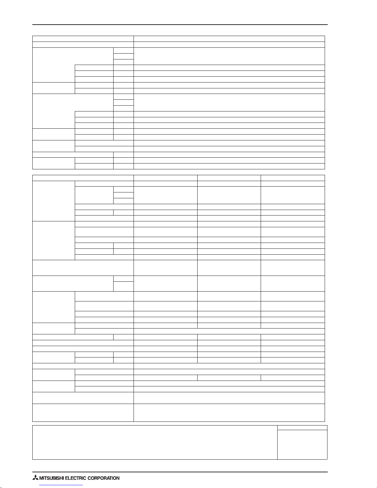
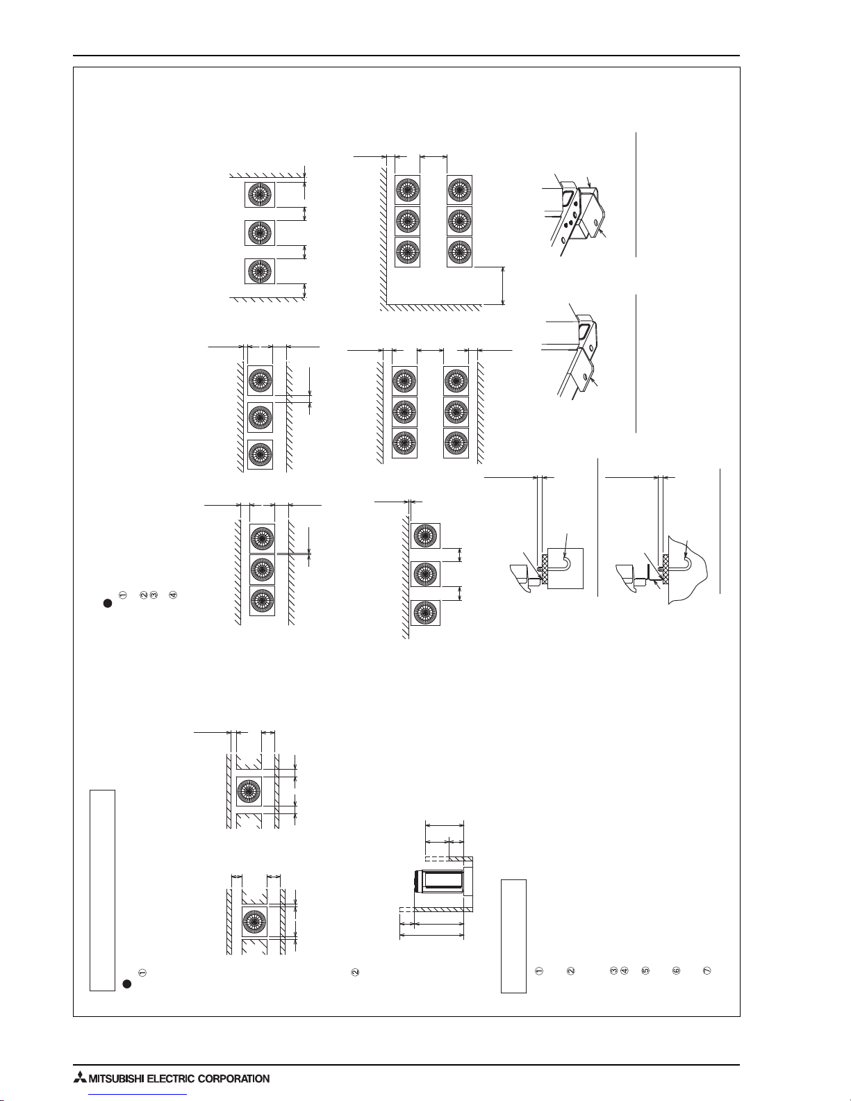
Secure enough space around the unit as shown in the figure below.
When the height of the walls on the front, back or on the sides <H>
exceeds the wall height limit as defined below, add the height
that exceeds the height limit <h> to the figures that are marked
with an asterisk.
1. Required space around the unit
In case of single installation
2. Foundation work
<Wall height limit> Front: Up to the unit height
Back: Up to 500 mm from
the unit bottom
Side: Up to the unit height
<field supply required>
<field supply required>
Detachable leg
Detachable leg
Corner of the
installation leg
M10 anchor bolt
<field supply required>
30 mm max.
• With a space of at least
300 mm to the wall on
the back of the unit
•
With a space of at least
100 mm to the wall on
the back of the unit
30 mm max.
<Side view>
H
h
h
H
Front
<Top view> <Top view>
Front
Corner of the
installation leg
M10 anchor bolt
<field supply required>
Front
Unit height
<To be left open>
<To be left open>
<To be left open>
<To be left open>
<To be left open>
<To be left open>
<To be left open>
30 min.
450 min.
450 min.
15 min.*
15 min.*
50 min.*
50 min.*
300 min.*
450 min.*
100 min.*
450 min.*
300 min.*450 min.*
100 min.*450 min.*
100 min.
450 min.*
450 min.
450 min.
100 min.*
15 min.*
300 min.*900 min.300 min.*
300 min.*900 min.
1000 min.*
500
When the pipes or cables are routed at the bottom of the unit,
make sure that the through hole at the base of the unit does not get blocked
with the installation base.
Refer to the Installation Manual when installing units on an installation base.
In case of collective installation
When multiple units are installed adjacent to each other, secure enough space to allow
for air circulation and walkway between groups of units as shown in the figures below.
At least two sides must be left open.
As with the single installation, add the height that exceeds the height limit <h>
to the figures that are marked with an asterisk.
If there is a wall at both the front and the rear of the unit, install up to six units
consecutively in the side direction and provide a space of 1000 mm or more as inlet space/
passage space for each six units.
Take into consideration the surface strength, water drainage route,
piping route, and wiring route when preparing the installation site.
<Note that the drain water comes out of the unit during operation.>
Build the foundation in such way that the corner of the installation leg is
securely supported as shown in the right figure. (Fig.A, B)
When using a rubber isolating cushion, please ensure it is large enough
to cover the entire width of each of the unit's legs.
The protrusion length of the anchor bolt must not exceed 30 mm. (Fig.A, B)
Use four fixing plates as shown in the right figure <field supply required>
when using post-installed anchor bolts. (Fig.C, D)
To prevent small animals and water and snow from entering the unit and damaging its parts,
close the gap around the edges of through holes for pipes and wires with
filler plates <field supply required>.
<Unit: mm>
Front
Front
Wall <H>
Wall <H>
Wall <H>
Wall <H>
Wall <H>
Wall <H> Wall <H>
Wall <H>
<To be left open>
<To be left open>
Front
<To be left open>
<Unit: mm>
Front
Wall <H>
Wall <H>
Front
Front
Front
Front
Front
Front
Fixing plate
Fixing plate
Fig.D (with detachable legs)
Fig.C (without detachable legs)
Fig.B (with detachable legs)
Fig.A (without detachable legs)
PUHY-RP200, 250, 300, 350YJM-B(-BS)
Unit : mm
17
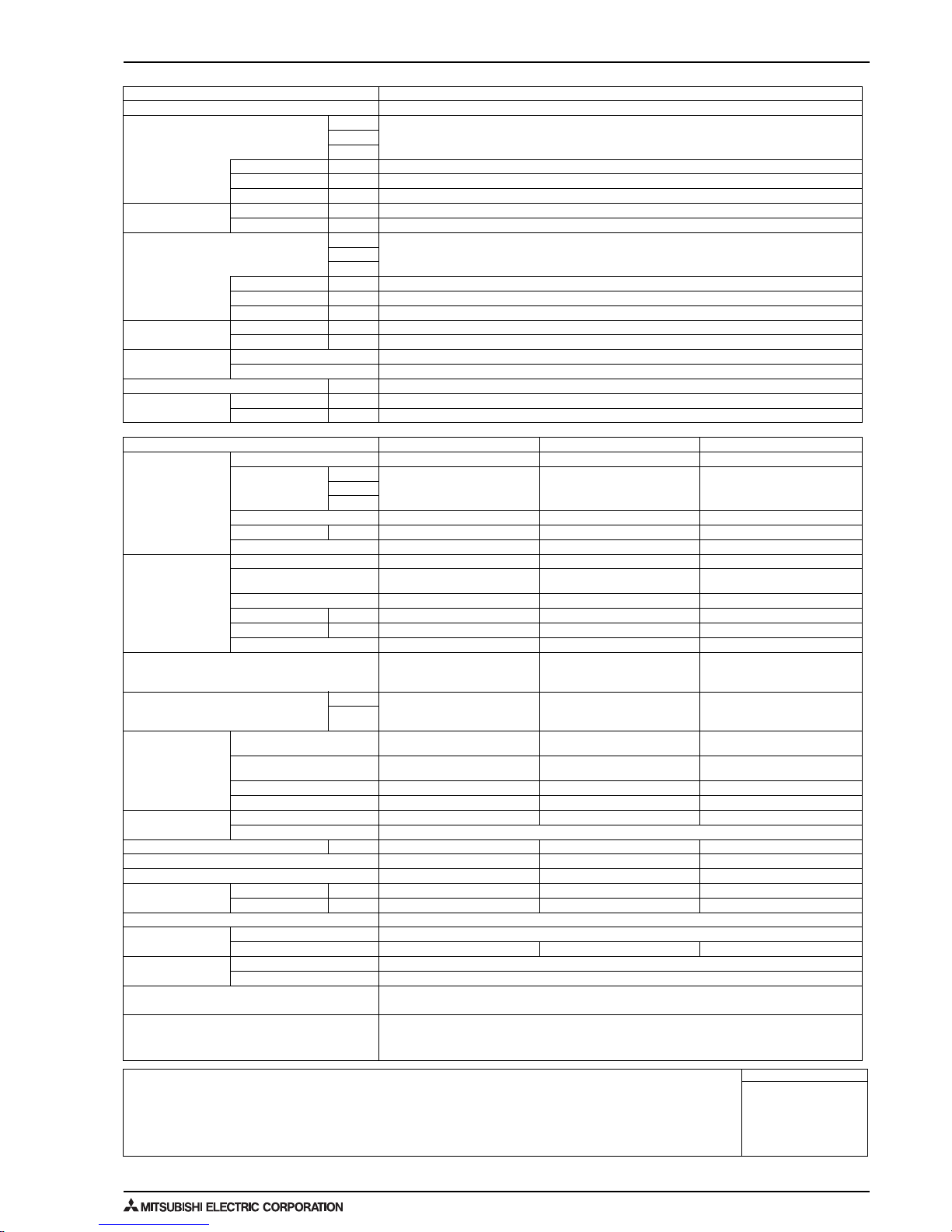
2. EXTERNAL DIMENSIONS
OUTDOOR UNITS
Detachable leg
Note 2*
Note 1. Connect the pipes as shown in the figure above. Refer to the table above for the pipe size.
2. The detachable leg can be removed at site.
3. Twinning pipes should not be tilted more than 15 degrees from the horizontal plane.
Be sure to see the Installation Manual for details of Twinning pipe installation.
4. The pipe section before the Twinning pipe (sections "a" and "b" in the figure) must have at least 500 mm of straight section
(*including the straight pipe that is supplied with the Twinning pipe).
5. Only use the Twinning pipe by Mitsubishi (optional parts).
ø19.05
ø41.28
a
Outdoor unit 2
760
920 30 920
ø9.52
RP350
ø28.58ø12.7
RP300
ø22.2ø12.7
RP250
PUHY-RP300YJM-B(-BS)
PUHY-RP350YJM-B(-BS)
PUHY-RP650YSJM-B(-BS)
PUHY-RP300YJM-B(-BS)
PUHY-RP300YJM-B(-BS)
PUHY-RP600YSJM-B(-BS)
PUHY-RP250YJM-B(-BS)
PUHY-RP300YJM-B(-BS)
PUHY-RP550YSJM-B(-BS)
PUHY-RP250YJM-B(-BS)
PUHY-RP250YJM-B(-BS)
PUHY-RP500YSJM-B(-BS)
PUHY-RP200YJM-B(-BS)
PUHY-RP250YJM-B(-BS)
PUHY-RP450YSJM-B(-BS)
Twinning pipe~Outdoor unit
d or f
Gas
Liquid
c or e
RP200
Unit model
b
Gas
Liquid
Outdoor unit 1
ø9.52 ø19.05
ø22.2
(60)
1650
1710
Intake
air
Outdoor unit 2Outdoor unit 1
Discharge air
Intake
air
Intake
air
Left side view
To indoor unit
Front view
c
d
b
a
f
e
Gas Twinning pipe <optional parts>
Liquid Twinning pipe <optional parts>
To indoor unit
Twinning pipe connection size
PUHY-RP400YSJM-B(-BS)
PUHY-RP200YJM-B(-BS)
PUHY-RP200YJM-B(-BS)
Package unit name
Component unit name
Outdoor Twinning Kit (optional parts)
Indoor unit~Twinning pipe
ø34.93
ø15.88
CMY-RP100VBK
PUHY-RP400, 450, 500, 550, 600, 650YSJM-B(-BS)
Unit : mm

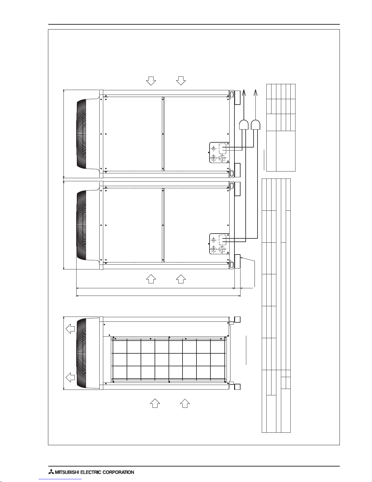
2. EXTERNAL DIMENSIONS
OUTDOOR UNITS 18
Note 2*
Detachable leg
Note 1. Connect the pipes as shown in the figure above. Refer to the table above for the pipe size.
2. The detachable leg can be removed at site.
3. Twinning pipes should not be tilted more than 15 degrees from the horizontal plane.
Be sure to see the Installation Manual for details of Twinning pipe installation.
4. The pipe section before the Twinning pipe (sections "a" , "b" , "c" and "d" in the figure) must have at least 500 mm of straight section
(*including the straight pipe that is supplied with the Twinning pipe).
5. Only use the Twinning pipe by Mitsubishi (optional parts).
(60)
1710
30
920
1650
760
920
30
920
Liquid
PUHY-RP250YJM-B(-BS)
PUHY-RP700YSJM-B(-BS)
CMY-RP200VBK
ø19.05
ø41.28
ø19.05
ø34.93
d
c
a
Gas
b
Twinning pipe connection size
Gas
PUHY-RP250YJM-B(-BS)
Liquid
PUHY-RP250YJM-B(-BS)
Outdoor unit 3
PUHY-RP300YJM-B(-BS)
Outdoor unit 1
PUHY-RP800YSJM-B(-BS)
Outdoor unit 2
Component unit name
PUHY-RP250YJM-B(-BS)
PUHY-RP250YJM-B(-BS)
PUHY-RP250YJM-B(-BS)
Package unit name
Outdoor Twinning Kit (optional parts)
Indoor unit~Twinning pipe 2
PUHY-RP250YJM-B(-BS)
Twinning pipe 1~Twinning pipe 2
PUHY-RP750YSJM-B(-BS)
PUHY-RP200YJM-B(-BS) PUHY-RP300YJM-B(-BS)
PUHY-RP300YJM-B(-BS)
PUHY-RP300YJM-B(-BS)
PUHY-RP900YSJM-B(-BS)
PUHY-RP250YJM-B(-BS)
PUHY-RP300YJM-B(-BS)
PUHY-RP300YJM-B(-BS)
PUHY-RP850YSJM-B(-BS)
Twinning pipe~Outdoor unit
ø12.7
RP250
RP200
ø9.52
Liquid
Gas
e or g or i f or h or j
ø19.05
ø22.2ø9.52
RP300
ø22.2
Unit model
f
e
To indoor unit
To indoor unit
i
b
a
j
c
d
g
h
Front view
Liquid Twinning pipe 1
<optional parts>
Gas Twinning pipe 1
<optional parts>
Liquid Twinning pipe 2
<optional parts>
Gas Twinning pipe 2
<optional parts>
Outdoor unit 3
Left side view
Outdoor unit 2Outdoor unit 1
Intake
air
Intake
air
Intake
air
Discharge air
PUHY-RP700, 750, 800, 850, 900YSJM-B(-BS)
Unit : mm
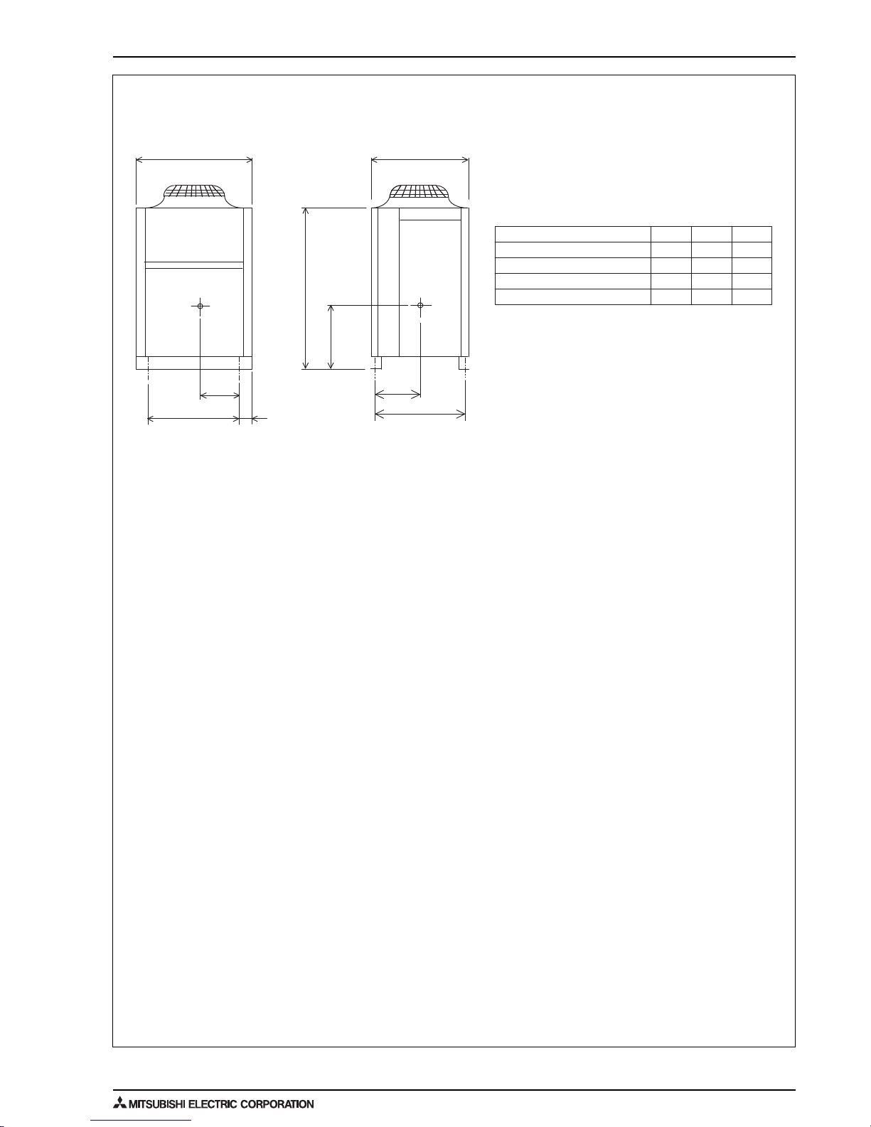
19
3. CENTER OF GRAVITY
OUTDOOR UNITS
3. CENTER OF GRAVITY
PUHY-RP200, RP250, RP300, RP350YJM-B(-BS)
760
80
Y
724
1410
Z
920
X
760
Model X Y Z
Unit: mm
330 337 550
325 342 550
325 352 550
325 352 550
PUHY-RP200YJM-B(-BS)
PUHY-RP250YJM-B(-BS)
PUHY-RP300YJM-B(-BS)
PUHY-RP350YJM-B(-BS)
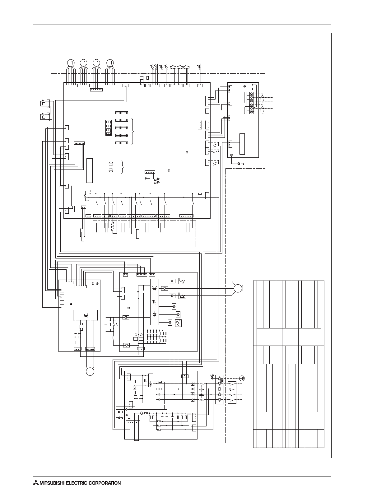
4. ELECTRICAL WIRING DIAGRAMS
OUTDOOR UNITS 20
4. ELECTRICAL WIRING DIAGRAMS
PUHY-RP200, 250, 300, 350YJM-B(-BS)
HIC bypass, Controls refrigerant
flow in HIC circuit
Oil flow control
SLEV
Refrigerant charging port for
auto-charge
SV8
SV5b
Outdoor unit heat exchanger
capacity control
SV3
Capacity control, Refrigerant
phase control in auto-cleaning
Middle pressure
63HS2
Pressure protection for pre-
existing pipes
63H2
For opening/closing the bypass
circuit
For opening/closing the bypass
circuit
Solenoid
valve
Pipe temperature
Z24, 25
Thermistor
Discharge pipe temperature
ACC inlet pipe temperature
Subcooled liquid refrigerant
temperature
OA temperature
IPM temperature
Function setting connector
THHS
TH7
TH6
TH5
TH4
TH3
Power supply
Explanation
Indoor/Outdoor transmission
cable
Central control transmission
cable
Terminal
block
TB7
TB3
TB1
Symbol
Pressure control, Refrigerant flow
rate control
DC reactor
DCL
SV1a
LEV2a, b
LEV1
Linear
expansion
valve
Solenoid
valve
CT12, 22, 3
CH11
Crankcase heater (for heating the compressor)
Current sensor (AC)
Magnetic relay (inverter main circuit)
72C
Low pressure
Discharge pressure
High pressure protection for the
outdoor unit
Pressure
switch
Pressure
sensor
63LS
63H1
Symbol
Explanation
4-way valve
21S4a, b
For opening/closing the bypass
circuit under the O/S
SV1b
SV9
63HS1
<Symbol explanation>
*1. Single-dotted lines indicate wiring
not supplied with the unit.
*2. Dot-dash lines indicate the control
box boundaries.
*3. Refer to the Data book for connecting
input/output signal connectors.
*4. Daisy-chain terminals (TB3) on the
outdoor units in the same refrigerant
system together.
*5. Faston terminals have a locking
function. Make sure the terminals
are securely locked in place after
insertion. Press the tab on the
terminals to remove them.
*6. Control box houses high-voltage parts.
Before inspecting the inside of the
control box, turn off the power, keep
the unit off for at least 10 minutes,
and confirm that the voltage between
FT-P and FT-N on INV Board has dropped
to DC20V or less.
SV8
X14
CN510
yellow
165
SV3
SV1b
63HS2
312
CN992
yellow
123
M
SLEV
65432
1
CNLVD
blue
3112
P
63H2
1
3
DCL
M1 M2
SV1a
Z3
21
M-NET power
supply circuit
C5
LED3: CPU in
operation
LED1: Normal
operation
SC-L1
SC-L2
1
2
W
U
SC-W
1
Z5
R1R2R3
C3
C2
F3F2F1
Z1 Z2
R4
D1
R5
R6
C11
DB1
C7C8C9
C10
C4
C1
C6
Power Source
3N~
50/60Hz
380/400/415V
N
L3L2L1
TB1
N
L3L2L1
L
F4
AC250V
6.3A T
black
white
red
3
1
CN3
green
TB24
N
TB23
L3
TB22
L2
TB21
L1
CN1B
4131
CN1A
UUU
F1,F2,F3
AC250V
6.3A T
U
Z4
DSA
CN2
653
1
Noise
Filter
U
ZNR01
U
31
CN5
red
3
CN4
blue
1
471
CNINV
CNVDC
4
1
FAN Board
F01
DC700V
4A T
C630
C631
R631
R630
IPM
CN18V
blue
CN4
red
CN5
21 1 3 12
234
1
CN21
blue
CN22
red
654
3
LED2: Error
Fan motor
(Heat exchanger)
M
3~
V
C100
R1 R5
*5
black
red
2
43
1
72C
black
red
SC-P1
SC-P2
4
CN1
1
LED1: Normal operation (lit)
/ Error(blink)
CN5V
yellow
CN6
21 3 1
CN4
1
2
CN2
152
7
1
CNTYP
black
C1
RSH1
THHS
*6
FT-P
FT-N
P
N
INV Board
+
+-
+
+++
+++
+
R34
C30
C32
C34
C36
R30
R32
C31
C33
C35
C37
R31
R33
black
white
red
R35
CT3
SC-L3
IPM
SC-U
SC-V
CT12 CT22
red white black
blackwhitered
U
V
W
MS
3~
Motor
(Compressor)
Central control
transmission
cable
Indoor/Outdoor
transmission
cable
Indoor/Outdoor
transmission
cable
*4
TP2TP1
TB7
SM2M1
TB3
M-NET Board
13
CN04
red
LED1: Power supply to
Indoor/Outdoor transmission line
CN102
4321
CNS2
yellow
21 5432
CNIT
red
1
63H1
P
LEV2b
M
LEV2a
M
M
LEV1
12345
6
CNLVA
CNLVB
red
12345
6
54321
6
CNLVC
red
3
1
CNTYP2
black
Z24
321
Z25
CNTYP5
green
CNTYP4
green
432
1
CN213
red
CN212
2
1
CN990
2
1
TH6
TH7
TH3
TH5
213
63LS
63HS1
213
TH4
321
CN202
red
CN201
231
CN211
2
1
red
CNIT
yellow
CNS2
51234
OFF
ON
14
14
CN41
CN40
CN102
4321
CN3D
123
red
CN3S
123
blue
CN3N
123
*3
CNAC
red
21
F01
AC250V
3.15A T
631
SV9
X09
CN508
black
X06
X07
135
6
CN507
red
6
3
SV5b
CN506
X05
3
1
21S4a
CN504
green
X04
X03
CH11
3
1
CN503
blue
2
1
CN502
X02
X01
21S4b
1
1
CN501
2
3
CNAC2
black
6
5
72C
1
2
CN72
red
31
CNDC
pink
12
CNT01
13 12 21 21
CN801
yellow
CNT02
CN332
blue
CN4
CN2
752
1
CPU power
supply circuit
Power failure
detection circuit
Control Board
LED1
SW1
ONOFF
1
10
SW2
ONOFF
1
10
SW3
ONOFF
1
10
SW4
ONOFF
1
10
ONOFF
1
10
SW5
543
12V
1
CN51
*3
SWU2 SWU1
10's
digit
1's
digit
Unit address
setting
LED1
Display
setting
Function
setting
Compressor ON/OFF output
Error detection output
TB7 Power
selecting
connector
LED3: Lit when powered
LED2: CPU in operation
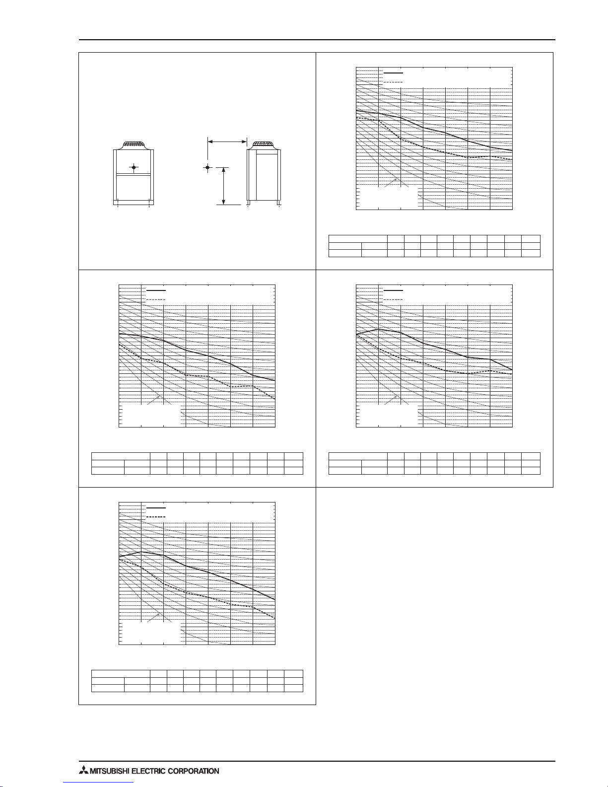
21
5. SOUND LEVELS
OUTDOOR UNITS
5. SOUND LEVELS
Measurement condition
PUHY-RP200, 250, 300, 350YJM-B(-BS)
Measurement
location
1m
1m
63 125 250 500 1k 2k 4k 8k dB(A)
Standard
50/60Hz 65.5 64.0 61.5 56.0 53.0 48.5 45.0 43.0 59.0
Low noise mode
50/60Hz 61.5 60.0 49.5 45.0 42.0 39.0 40.0 38.0 50.0
When Low noise mode is set,the A/C system's capacity is limited. The system could return to normal operation
from Low noise mode automatically in the case that the operation condition is severe.
10
20
30
40
50
60
70
80
90
63 125 250 500 1k 2k 4k 8k
NC-40
NC-30
NC-20
NC-60
NC-50
NC-70
Octave band central frequency (Hz)
Octave band sound level (dB)
Approximate minimum
audible limit on
continuous noise
Stand 50/60Hz
Low 50/60Hz
Sound level of PUHY-RP300YJM-B(-BS)
63 125 250 500 1k 2k 4k 8k dB(A)
Standard
50/60Hz 62.5 61.0 58.5 53.0 50.0 45.5 39.0 36.0 56.0
Low noise mode
50/60Hz 56.5 48.5 46.0 39.0 38.5 32.5 33.0 25.5 44.0
When Low noise mode is set,the A/C system's capacity is limited. The system could return to normal operation
from Low noise mode automatically in the case that the operation condition is severe.
10
20
30
40
50
60
70
80
90
63 125 250 500 1k 2k 4k 8k
NC-40
NC-30
NC-20
NC-60
NC-50
NC-70
Octave band central frequency (Hz)
Octave band sound level (dB)
Approximate minimum
audible limit on
continuous noise
Stand 50/60Hz
Low 50/60Hz
Sound level of PUHY-RP200YJM-B(-BS)
63 125 250 500 1k 2k 4k 8k dB(A)
Standard
50/60Hz 62.0 65.0 63.0 57.0 53.5 49.0 48.0 42.0 60.0
Low noise mode
50/60Hz 62.0 54.0 48.5 46.0 41.5 40.0 41.5 39.5 50.0
When Low noise mode is set,the A/C system's capacity is limited. The system could return to normal operation
from Low noise mode automatically in the case that the operation condition is severe.
10
20
30
40
50
60
70
80
90
63 125 250 500 1k 2k 4k 8k
NC-40
NC-30
NC-20
NC-60
NC-50
NC-70
Octave band central frequency (Hz)
Octave band sound level (dB)
Approximate minimum
audible limit on
continuous noise
Stand 50/60Hz
Low 50/60Hz
Sound level of PUHY-RP350YJM-B(-BS)
63 125 250 500 1k 2k 4k 8k dB(A)
Standard
50/60Hz 59.0 62.0 60.0 54.0 50.5 46.0 41.0 35.0 57.0
Low noise mode
50/60Hz 58.0 53.5 44.0 39.0 36.5 32.5 31.0 24.5 44.0
When Low noise mode is set,the A/C system's capacity is limited. The system could return to normal operation
from Low noise mode automatically in the case that the operation condition is severe.
10
20
30
40
50
60
70
80
90
63 125 250 500 1k 2k 4k 8k
NC-40
NC-30
NC-20
NC-60
NC-50
NC-70
Octave band central frequency (Hz)
Octave band sound level (dB)
Approximate minimum
audible limit on
continuous noise
Stand 50/60Hz
Low 50/60Hz
Sound level of PUHY-RP250YJM-B(-BS)

5. SOUND LEVELS
OUTDOOR UNITS 22
Measurement condition
PUHY-RP400, 450, 500, 550, 600, 650YSJM-B(-BS)
Measurement
location
1m
1m
63 125 250 500 1k 2k 4k 8k dB(A)
Standard
50/60Hz 62.0 65.0 63.0 57.0 53.5 49.0 44.0 38.0 60.0
Low noise mode
50/60Hz 61.0 56.5 47.0 42.0 39.5 35.5 34.0 27.5 47.0
When Low noise mode is set,the A/C system's capacity is limited. The system could return to normal operation
from Low noise mode automatically in the case that the operation condition is severe.
10
20
30
40
50
60
70
80
90
63 125 250 500 1k 2k 4k 8k
NC-40
NC-30
NC-20
NC-60
NC-50
NC-70
Octave band central frequency (Hz)
Octave band sound level (dB)
Approximate minimum
audible limit on
continuous noise
Stand 50/60Hz
Low 50/60Hz
Sound level of PUHY-RP500YSJM-B(-BS)
63 125 250 500 1k 2k 4k 8k dB(A)
Standard
50/60Hz 65.5 64.0 61.5 56.0 53.0 48.5 42.0 39.0 59.0
Low noise mode
50/60Hz 59.5 51.5 49.0 42.0 41.5 35.5 36.0 28.5 47.0
When Low noise mode is set,the A/C system's capacity is limited. The system could return to normal operation
from Low noise mode automatically in the case that the operation condition is severe.
10
20
30
40
50
60
70
80
90
63 125 250 500 1k 2k 4k 8k
NC-40
NC-30
NC-20
NC-60
NC-50
NC-70
Octave band central frequency (Hz)
Octave band sound level (dB)
Approximate minimum
audible limit on
continuous noise
Stand 50/60Hz
Low 50/60Hz
Sound level of PUHY-RP400YSJM-B(-BS)
63 125 250 500 1k 2k 4k 8k dB(A)
Standard
50/60Hz 66.0 66.0 63.5 58.0 55.0 50.5 46.5 43.5 61.0
Low noise mode
50/60Hz 63.5 61.0 50.5 46.0 43.0 40.0 40.5 38.0 51.0
When Low noise mode is set,the A/C system's capacity is limited. The system could return to normal operation
from Low noise mode automatically in the case that the operation condition is severe.
10
20
30
40
50
60
70
80
90
63 125 250 500 1k 2k 4k 8k
NC-40
NC-30
NC-20
NC-60
NC-50
NC-70
Octave band central frequency (Hz)
Octave band sound level (dB)
Approximate minimum
audible limit on
continuous noise
Stand 50/60Hz
Low 50/60Hz
Sound level of PUHY-RP550YSJM-B(-BS)
63 125 250 500 1k 2k 4k 8k dB(A)
Standard
50/60Hz 64.0 64.5 62.5 56.5 53.0 48.5 43.0 38.5 59.5
Low noise mode
50/60Hz 60.5 54.5 48.0 42.0 40.5 35.5 35.0 28.0 47.0
When Low noise mode is set,the A/C system's capacity is limited. The system could return to normal operation
from Low noise mode automatically in the case that the operation condition is severe.
10
20
30
40
50
60
70
80
90
63 125 250 500 1k 2k 4k 8k
NC-40
NC-30
NC-20
NC-60
NC-50
NC-70
Octave band central frequency (Hz)
Octave band sound level (dB)
Approximate minimum
audible limit on
continuous noise
Stand 50/60Hz
Low 50/60Hz
Sound level of PUHY-RP450YSJM-B(-BS)
63 125 250 500 1k 2k 4k 8k dB(A)
Standard
50/60Hz 68.5 67.0 64.5 59.0 56.0 51.5 48.0 46.0 62.0
Low noise mode
50/60Hz 64.5 63.0 52.5 48.0 45.0 42.0 43.0 41.0 53.0
When Low noise mode is set,the A/C system's capacity is limited. The system could return to normal operation
from Low noise mode automatically in the case that the operation condition is severe.
10
20
30
40
50
60
70
80
90
63 125 250 500 1k 2k 4k 8k
NC-40
NC-30
NC-20
NC-60
NC-50
NC-70
Octave band central frequency (Hz)
Octave band sound level (dB)
Approximate minimum
audible limit on
continuous noise
Stand 50/60Hz
Low 50/60Hz
Sound level of PUHY-RP600YSJM-B(-BS)
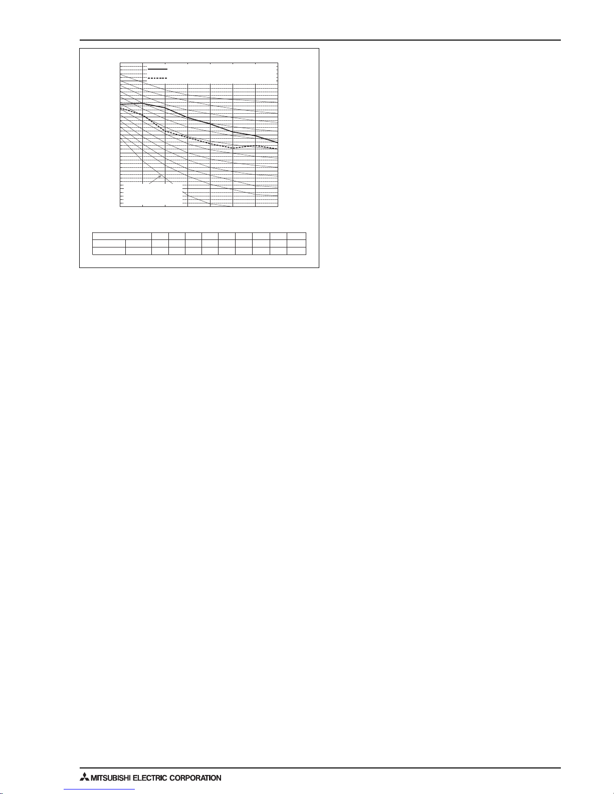
23
5. SOUND LEVELS
OUTDOOR UNITS
63 125 250 500 1k 2k 4k 8k dB(A)
Standard
50/60Hz 67.0 67.5 65.0 59.5 56.0 51.5 49.5 45.5 62.5
Low noise mode
50/60Hz 65.0 61.0 52.0 48.5 45.0 42.5 44.0 42.0 53.0
When Low noise mode is set,the A/C system's capacity is limited. The system could return to normal operation
from Low noise mode automatically in the case that the operation condition is severe.
10
20
30
40
50
60
70
80
90
63 125 250 500 1k 2k 4k 8k
NC-40
NC-30
NC-20
NC-60
NC-50
NC-70
Octave band central frequency (Hz)
Octave band sound level (dB)
Approximate minimum
audible limit on
continuous noise
Stand 50/60Hz
Low 50/60Hz
Sound level of PUHY-RP650YSJM-B(-BS)
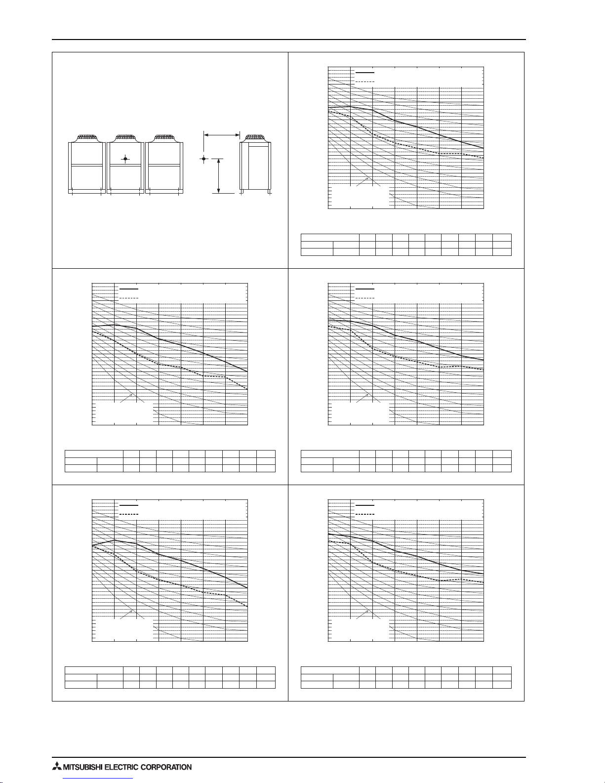
5. SOUND LEVELS
OUTDOOR UNITS 24
Measurement condition
PUHY-RP700, 750, 800, 850, 900YSJM-B(-BS)
Measurement
location
1m
1m
63 125 250 500 1k 2k 4k 8k dB(A)
Standard
50/60Hz 67.0 67.5 65.5 59.5 56.0 51.5 47.5 44.0 62.5
Low noise mode
50/60Hz 65.0 62.0 52.0 47.0 44.0 41.0 41.0 38.5 52.0
When Low noise mode is set,the A/C system's capacity is limited. The system could return to normal operation
from Low noise mode automatically in the case that the operation condition is severe.
10
20
30
40
50
60
70
80
90
63 125 250 500 1k 2k 4k 8k
NC-40
NC-30
NC-20
NC-60
NC-50
NC-70
Octave band central frequency (Hz)
Octave band sound level (dB)
Approximate minimum
audible limit on
continuous noise
Stand 50/60Hz
Low 50/60Hz
Sound level of PUHY-RP800YSJM-B(-BS)
63 125 250 500 1k 2k 4k 8k dB(A)
Standard
50/60Hz 65.5 66.5 64.5 58.5 55.0 50.5 45.5 40.0 61.5
Low noise mode
50/60Hz 63.0 57.5 50.0 44.0 42.5 37.5 37.0 30.0 49.0
When Low noise mode is set,the A/C system's capacity is limited. The system could return to normal operation
from Low noise mode automatically in the case that the operation condition is severe.
10
20
30
40
50
60
70
80
90
63 125 250 500 1k 2k 4k 8k
NC-40
NC-30
NC-20
NC-60
NC-50
NC-70
Octave band central frequency (Hz)
Octave band sound level (dB)
Approximate minimum
audible limit on
continuous noise
Stand 50/60Hz
Low 50/60Hz
Sound level of PUHY-RP700YSJM-B(-BS)
63 125 250 500 1k 2k 4k 8k dB(A)
Standard
50/60Hz 69.0 68.5 66.0 60.5 57.5 53.0 49.0 46.5 63.5
Low noise mode
50/60Hz 65.5 63.5 53.0 48.5 45.5 42.5 43.0 41.0 53.5
When Low noise mode is set,the A/C system's capacity is limited. The system could return to normal operation
from Low noise mode automatically in the case that the operation condition is severe.
10
20
30
40
50
60
70
80
90
63 125 250 500 1k 2k 4k 8k
NC-40
NC-30
NC-20
NC-60
NC-50
NC-70
Octave band central frequency (Hz)
Octave band sound level (dB)
Approximate minimum
audible limit on
continuous noise
Stand 50/60Hz
Low 50/60Hz
Sound level of PUHY-RP850YSJM-B(-BS)
63 125 250 500 1k 2k 4k 8k dB(A)
Standard
50/60Hz 64.0 67.0 65.0 59.0 55.5 51.0 46.0 40.0 62.0
Low noise mode
50/60Hz 63.5 59.0 49.5 44.5 41.5 37.5 36.0 29.5 49.0
When Low noise mode is set,the A/C system's capacity is limited. The system could return to normal operation
from Low noise mode automatically in the case that the operation condition is severe.
10
20
30
40
50
60
70
80
90
63 125 250 500 1k 2k 4k 8k
NC-40
NC-30
NC-20
NC-60
NC-50
NC-70
Octave band central frequency (Hz)
Octave band sound level (dB)
Approximate minimum
audible limit on
continuous noise
Stand 50/60Hz
Low 50/60Hz
Sound level of PUHY-RP750YSJM-B(-BS)
63 125 250 500 1k 2k 4k 8k dB(A)
Standard
50/60Hz 70.5 69.0 66.5 61.0 58.0 53.5 50.0 48.0 64.0
Low noise mode
50/60Hz 66.5 65.0 54.5 50.0 47.0 44.0 45.0 43.0 55.0
When Low noise mode is set,the A/C system's capacity is limited. The system could return to normal operation
from Low noise mode automatically in the case that the operation condition is severe.
10
20
30
40
50
60
70
80
90
63 125 250 500 1k 2k 4k 8k
NC-40
NC-30
NC-20
NC-60
NC-50
NC-70
Octave band central frequency (Hz)
Octave band sound level (dB)
Approximate minimum
audible limit on
continuous noise
Stand 50/60Hz
Low 50/60Hz
Sound level of PUHY-RP900YSJM-B(-BS)
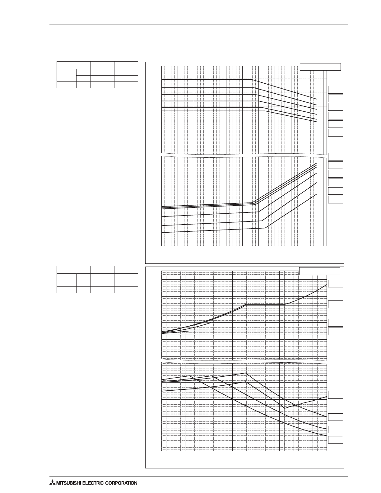
25
6. CAPACITY TABLES
OUTDOOR UNITS
6. CAPACITY TABLES
6-1. Correction by temperature
CITY MULTI could have various capacities at different designing temperatures. Using the nominal cooling/heating capacity values
and the ratios below, the capacity can be found for various temperatures.
Nominal
Cooling
Capacity
Input
kW
BTU/h
kW
Nominal
Heating
Capacity
Input
kW
BTU/h
kW
RP200YJM-B RP250YJM-B
22.4
76,400
5.68
28.0
95,500
7.62
25.0
85,300
5.69
31.5
107,500
7.22
RP200YJM-B RP250YJM-B
0.8
0.9
1.0
1.1
1.2
1.3
1.4
0.7
0.6
0.5
0.4
Ratio of power input
1.2
1.3
1.4
1.1
0.9
0.6
0.8
0.5
0.7
0.4
1.0
Ratio of heating capacity
Ratio of heating capacity and power input
-4 5 14 23 32 41 50 59
-20 -15 -10 -5 0 5 10 15
°FWB
°CWB
Outdoor Temperature
Indoor Temperature
15°CDB
59°FDB
20°CDB
68°FDB
25°CDB
77°FDB
27°CDB
80°FDB
15°CDB
59°FDB
20°CDB
68°FDB
25°CDB
77°FDB
27°CDB
80°FDB
PUHY-
PUHY-
-5
230325411050155920682577308635954010445113
°CDB
°FDB
Outdoor Temperature
0.6
0.8
0.9
1.0
1.2
1.1
0.7
0.6
0.5
0.4
Ratio of power input
1.3
1.4
1.2
1.0
0.9
0.8
0.7
1.1
Ratio of cooling capacity
Ratio of cooling capacity and power input
Indoor Temperature
24°CWB
75°FWB
22°CWB
72°FWB
20°CWB
68°FWB
18°CWB
64°FWB
16°CWB
61°FWB
15°CWB
59°FWB
24°CWB
75°FWB
22°CWB
72°FWB
20°CWB
68°FWB
18°CWB
64°FWB
16°CWB
61°FWB
15°CWB
59°FWB
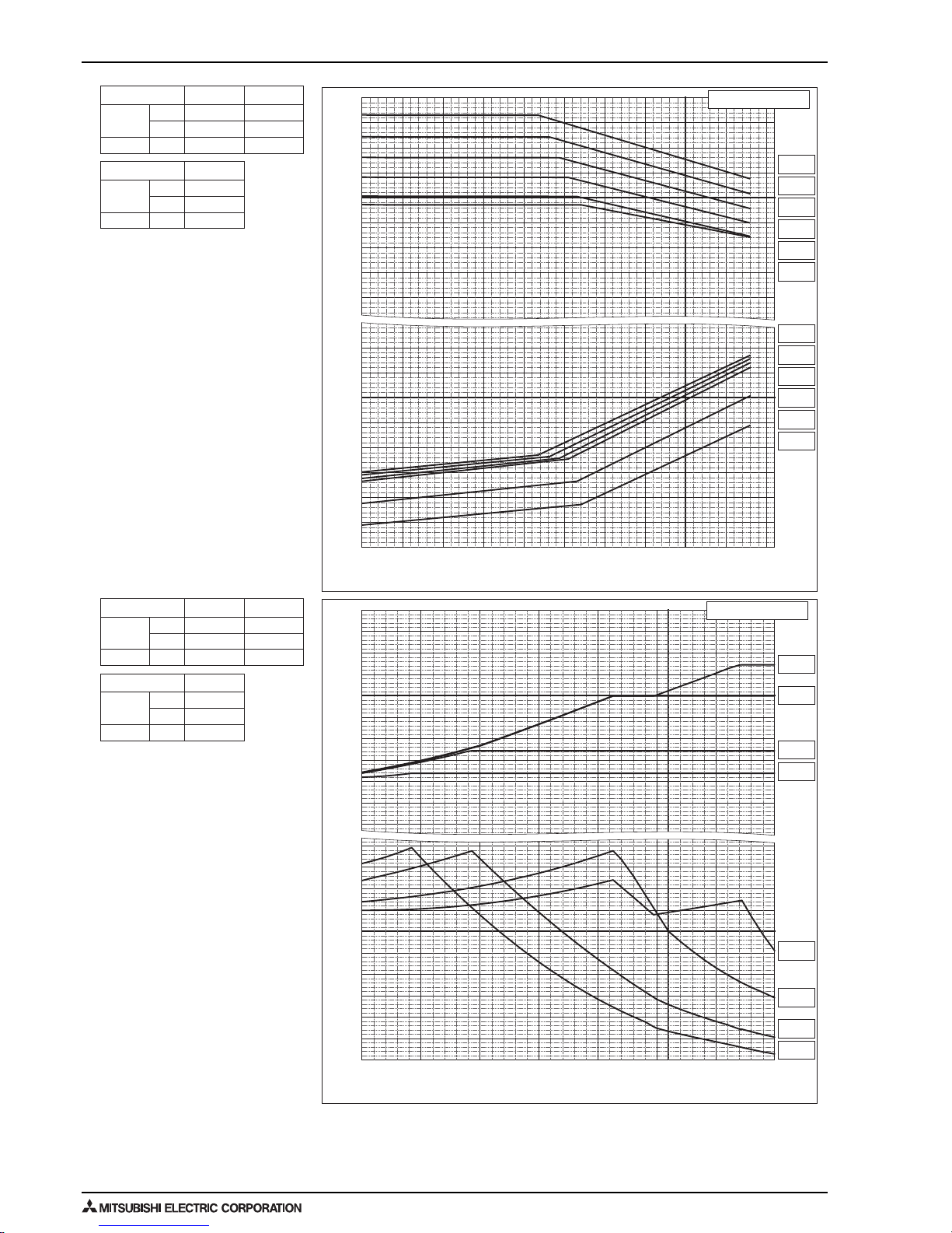
6. CAPACITY TABLES
OUTDOOR UNITS 26
Nominal
Cooling
Capacity
Input
kW
BTU/h
kW
Nominal
Heating
Capacity
Input
kW
BTU/h
kW
Nominal
Cooling
Capacity
Input
kW
BTU/h
kW
Nominal
Heating
Capacity
Input
kW
BTU/h
kW
PUHY-
RP300YJM-B RP350YJM-B
PUHY-
RP300YJM-B RP350YJM-B
PUHY-
RP400YSJM-B
PUHY-
RP400YSJM-B
33.5
114,300
8.98
40.0
136,500
11.79
37.5
128,000
9.42
45.0
153,500
12.60
45.0
153,500
11.87
50
170,600
11.38
0.8
0.9
1.0
1.1
1.2
1.3
1.4
0.7
0.6
0.5
0.4
Ratio of power input
1.2
1.3
1.4
1.1
0.9
0.6
0.8
0.5
0.7
0.4
1.0
Ratio of heating capacity
Ratio of heating capacity and power input
-4 5 142332415059
-20 -15 -10 -5 0 5 10 15
°FWB
°CWB
Outdoor Temperature
Indoor Temperature
15°CDB
59°FDB
20°CDB
68°FDB
25°CDB
77°FDB
27°CDB
80°FDB
15°CDB
59°FDB
20°CDB
68°FDB
25°CDB
77°FDB
27°CDB
80°FDB
-5
230325411050155920682577308635954010445113
°CDB
°FDB
Outdoor Temperature
0.6
0.8
0.9
1.0
1.2
1.1
0.7
0.6
0.5
0.4
Ratio of power input
1.3
1.4
1.2
1.0
0.9
0.8
0.7
1.1
Ratio of cooling capacity
Ratio of cooling capacity and power input
Indoor Temperature
24°CWB
75°FWB
22°CWB
72°FWB
20°CWB
68°FWB
18°CWB
64°FWB
16°CWB
61°FWB
15°CWB
59°FWB
24°CWB
75°FWB
22°CWB
72°FWB
20°CWB
68°FWB
18°CWB
64°FWB
16°CWB
61°FWB
15°CWB
59°FWB
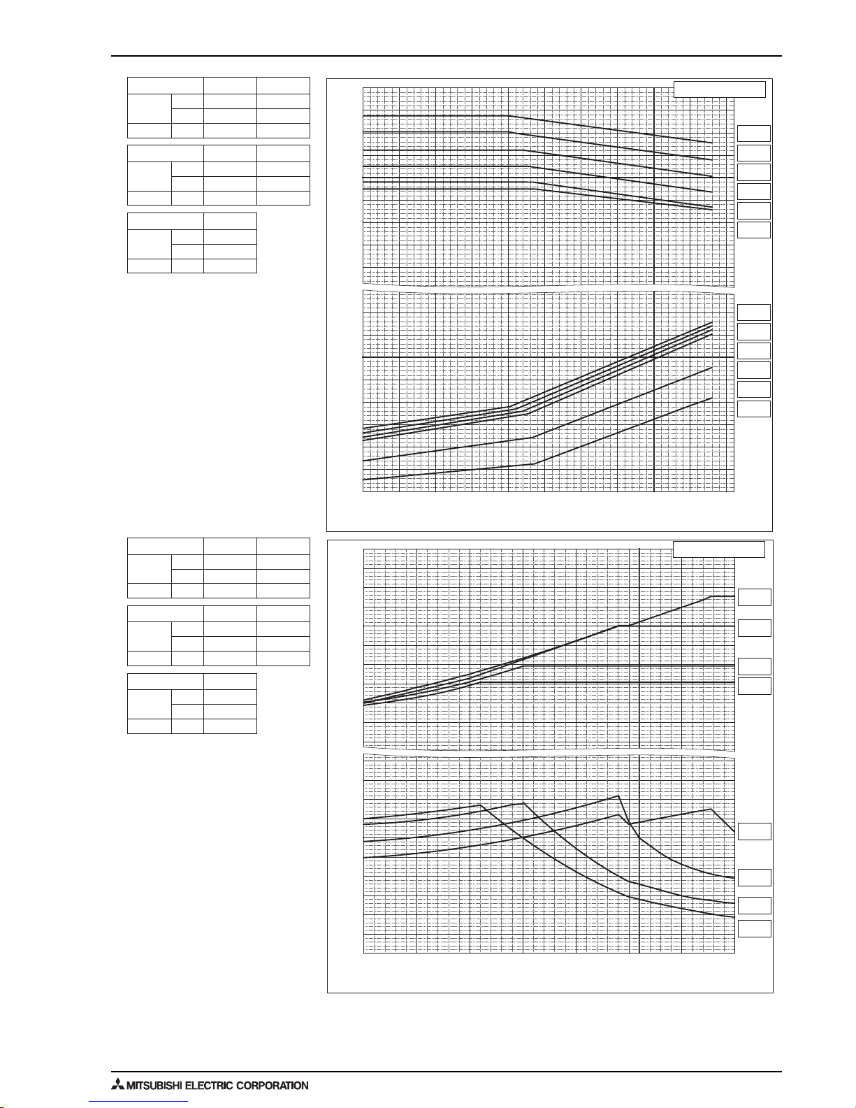
27
6. CAPACITY TABLES
OUTDOOR UNITS
Nominal
Cooling
Capacity
Input
kW
BTU/h
kW
Nominal
Heating
Capacity
Input
kW
BTU/h
kW
Nominal
Cooling
Capacity
Input
kW
BTU/h
kW
Nominal
Heating
Capacity
Input
kW
BTU/h
kW
Nominal
Cooling
Capacity
Input
kW
BTU/h
kW
Nominal
Heating
Capacity
Input
kW
BTU/h
kW
50.0
170,600
13.77
56.0
191,100
15.68
56.0
191,100
12.81
63.0
215,000
14.44
63.0
215,000
17.50
69.0
235,400
18.59
69.0
235,400
16.62
76.5
261,000
19.22
73.0
249,100
21.09
81.5
278,100
21.73
PUHY-
RP450YSJM-B
RP500YSJM-B
PUHY-
PUHY-
RP550YSJM-B P600YSJM-B
PUHY-
PUHY-
RP650YSJM-B
RP450YSJM-B
RP500YSJM-B
RP550YSJM-B RP600YSJM-B
RP650YSJM-B
PUHY-
0.8
0.9
1.0
1.1
1.2
1.3
1.4
0.7
0.6
0.5
0.4
Ratio of power input
1.2
1.3
1.4
1.1
0.9
0.6
0.8
0.5
0.7
0.4
1.0
Ratio of heating capacity
Ratio of heating capacity and power input
-4 5 14 23 32 41 50 59
-20 -15 -10 -5 0 5 10 15
°FWB
°CWB
Outdoor Temperature
Indoor Temperature
15°CDB
59°FDB
20°CDB
68°FDB
25°CDB
77°FDB
27°CDB
80°FDB
15°CDB
59°FDB
20°CDB
68°FDB
25°CDB
77°FDB
27°CDB
80°FDB
-5
230325411050155920682577308635954010445113
°CDB
°FDB
Outdoor Temperature
0.6
0.8
0.9
1.0
1.2
1.1
0.7
0.6
0.5
0.4
Ratio of power input
1.3
1.4
1.2
1.0
0.9
0.8
0.7
1.1
Ratio of cooling capacity
Ratio of cooling capacity and power input
Indoor Temperature
24°CWB
75°FWB
22°CWB
72°FWB
20°CWB
68°FWB
18°CWB
64°FWB
16°CWB
61°FWB
15°CWB
59°FWB
24°CWB
75°FWB
22°CWB
72°FWB
20°CWB
68°FWB
18°CWB
64°FWB
16°CWB
61°FWB
15°CWB
59°FWB
 Loading...