

Page 1

Air-Conditioners For Building Application
OUTDOOR UNIT
PUHY-RP-YJM-A (-BS)
For use with R410A
INSTALLATION MANUAL
For safe and correct use, please read this installation manual thoroughly before installing the air-conditioner unit.
INSTALLATIONSHANDBUCH
Zum sicheren und ordnungsgemäßen Gebrauch der Klimageräte das Installationshandbuch gründlich durchlesen.
MANUEL D’INSTALLATION
Veuillez lire le manuel d’installation en entier avant d’installer ce climatiseur pour éviter tout accident et vous assurer d’une utilisation correcte.
MANUAL DE INSTALACIÓN
Para un uso seguro y correcto, lea detalladamente este manual de instalación antes de montar la unidad de aire acondicionado.
MANUALE DI INSTALLAZIONE
Per un uso sicuro e corretto, leggere attentamente questo manuale di installazione prima di installare il condizionatore d’aria.
INSTALLATIEHANDLEIDING
Voor een veilig en juist gebruik moet u deze installatiehandleiding grondig doorlezen voordat u de airconditioner installeert.
MANUAL DE INSTALAÇÃO
Para segurança e utilização correctas, leia atentamente este manual de instalação antes de instalar a unidade de ar condicionado.
EΓXEIPI∆IO O∆HΓIΩN EΓKATAΣTAΣHΣ
°И· ·ЫК¿ПВИ· О·И ЫˆЫЩ‹ ¯Ъ‹ЫЛ, ·Ъ·О·ПВ›ЫЩВ ‰И·‚¿ЫВЩВ ЪФЫВ¯ЩИО¿ ·˘Щfi ЩФ ВБ¯ВИЪ›‰ИФ ВБО·Щ¿ЫЩ·ЫЛ˜ ЪИУ ·Ъ¯›ЫВЩВ ЩЛУ
ВБО·Щ¿ЫЩ·ЫЛ ЩЛ˜ МФУ¿‰·˜ ОПИМ·ЩИЫМФ‡.
РУКОВОДСТВО ПО УСТАНОВКЕ
Для осторожного и правильного использования прибора необходимо тщательно ознакомиться с данным руководством по
установке до выполнения установки кондиционера.
MONTAJ ELKMONTAJ ELK
MONTAJ ELK
MONTAJ ELKMONTAJ ELK
Emniyetli ve doqru biçimde naswl kullanwlacaqwnw öqrenmek için lütfen klima cihazwnw monte etmeden önce bu elkitabwnw dikkatle okuyunuz.
WW
TABITABI
W
TABI
WW
TABITABI
GB
D
FEINLPGRRUTRCZSVHGPOSL
INSTALLATIONSHANDBOK
Läs den här installationshandboken noga innan luftkonditioneringsenheten installeras, för säker och korrekt användning.
РЪКОВОДСТВО ЗА МОНТАЖ
За безопасна и правилна употреба, моля, прочетете внимателно това ръководство преди монтажа на климатизатора.
SWHRBGRO
Page 2

6
15
*
15
*
450
*
300
*
<A>
A
30
450
*
300
*
C
BB
C
A
100
450
*
100
*
BB
C
C
A
15
*
C
AAA
450 450
900
300
*
300
*
BB
C
C
A
[Fig. 6.0.1]
(1)
[Fig. 6.0.2]
<A> : Top view
<B> : Side view
<C> : When there is little space up to an obstruction
A : Front
B : Unit height
C : Back
D : Air outlet guide (Procured at the site)
(2)
(3)
(4)
240
45°
100
*
*
B
A
450 450
B
A
100*
450
A
50
50
*
*
<A>
*
A
CC
450
h
H
B
A
h
H
500
<B>
1000
C
*
D
50
7
[Fig. 7.0.1]
RP200 ~ RP350
8m
40°
2
8m
A
<C>
C
(mm)
1000
B
A
*
B
900 300
A : Front
B : Must be open
C :Wall height (H)
(mm)
Page 3

[Fig. 8.1.1]
8
<A> Without detachable leg
<B> With detachable leg
30mm
A
A : M10 anchor bolt procured at the site.
B :Corner is not seated.
C : Fixing bracket for hole-in anchor bolt (3 locations to fix
with screws).
D : Detachable leg
B
C
[Fig. 8.1.2]
D
9
[Fig. 9.2.1]
[RP200 ~ RP350]
A
[RP400 ~ RP650]
unit 1
30mm
A
A
B C D
a b c d
B
C
CC
unit 2
B
C D
A
A : Screws
9.2
A
A
B
e
b
a
C
C
C
unit 1
c d e
C
unit 2
D
CC
C
A
[RP700 ~ RP900]
A
A1
A
A2A1
A
B C D
a b c d
E
unit 3
unit 2unit 1
A2
E
B
C
CC
AA
A3
A
A4
E
B C D
a b c d
B
C
CCC
e
C
C
e
C
A
A1
A
1
unit 3
unit 2unit 1
A
A2
E
A : Outdoor unit
B : First branch
C : Indoor unit
D : Cap
E : Outdoor twinning kit
A
A
2
A
B
E
b
a
C
AA
A3
A4
E
C
c d e
C
A
B
b
a
c d e
C
D
CC
C
D
CC
C
3
Page 4

9
A (mm)
Å Outdoor model
RP200
RP250
RP300
RP350
RP400
RP450
RP500
RP550
RP600
RP650
RP700
RP750
RP800
RP850
RP900
*1 The pipe sizes listed in columns A1 to A3 in this table correspond to the
sizes for the models listed in the unit 1, 2, and 3 columns. When the order
of the models for unit 1, 2, and 3 change, make sure to use the appropriate
pipe size.
*2 ø25.4 for R22
B, C, D (mm)
Î Total capacity of indoor units
81 ~ 160
161 ~ 330
331 ~ 480
481 ~ 630
631 ~
Unit combination A A1 *1 A2 *1 A3 *1 A4
unit1
RP200
RP200
RP250
RP250
RP300
RP300
RP200
RP250
RP250
RP250
RP300
~ 80
unit2
-
-
-
RP200
RP250
RP250
RP300
RP300
RP350
RP250
RP250
RP250
RP300
RP300
-
-
-
-
ı Liquid pipe
unit3
-
-
-
-
-
-
-
-
-
RP250
RP250
RP300
RP300
RP300
ø9.52
ø12.7
ø12.7
ø15.88
ø15.88
ø19.05
ı Liquid pipe
ø12.7
ø12.7
ø12.7
ø15.88
ø15.88
ø15.88
ø15.88
ø15.88
ø19.05
ø19.05
ø19.05
ø19.05
ø19.05
ø19.05
ø19.05
Ç Gas pipe
ø25.4 or ø28.58
ø31.75 or ø34.93
ø38.1 or ø34.93
Ç Gas pipe
ø28.58*2
ø28.58
ø28.58
ø34.93
ø34.93
ø34.93
ø34.93
ø34.93
ø34.93
ø41.28
ø41.28
ø41.28
ø41.28
ø41.28
ø41.28
ø15.88
ø19.05
ø41.28
9.2
ı Liquid pipe
-
-
-
ø9.52
ø9.52
ø9.52
ø9.52
ø12.7
ø12.7
ø9.52
ø9.52
ø9.52
ø9.52
ø12.7
Ç Gas pipe
-
-
-
ø19.05
ø19.05
ø22.2
ø22.2
ø22.2
ø22.2
ø19.05
ø22.2
ø22.2
ø22.2
ø22.2
ı Liquid pipe
-
-
-
ø9.52
ø9.52
ø9.52
ø12.7
ø12.7
ø12.7
ø9.52
ø9.52
ø9.52
ø12.7
ø12.7
Ç Gas pipe
-
-
-
-
ø19.05
ø22.2
ø22.2
ø22.2
ø22.2
ø28.58
ø22.2
ø22.2
ø22.2
ø22.2
ø22.2
ı Liquid pipe
-
-
-
-
-
-
-
-
-
ø9.52
ø9.52
ø12.7
ø12.7
ø12.7
Ç Gas pipe
-
-
-
-
-
-
-
-
-
ø22.2
ø22.2
ø22.2
ø22.2
ø22.2
ı Liquid pipe
-
-
-
-
-
-
-
-
-
ø19.05
ø19.05
ø19.05
ø19.05
ø19.05
Ç Gas pipe
-
-
-
-
-
-
-
-
-
ø34.93
ø34.93
ø34.93
ø34.93
ø34.93
a, b, c, d, e (mm)
‰ Model number
15,20,25,32,40
50,63,71,80
100,125,140
200,250
Ï Downstream unit model total
Ó The 1st branch of P450 ~ P650
The 1st branch of P700, P750, P800
È
~ 200
201 ~ 400
401 ~ 650
651 ~
ı Liquid pipe
ø6.35
ø9.52
ø9.52
ø12.7
Ç Gas pipe
ø12.7
ø15.88
ø19.05
ø28.58
Ì Joint
CMY-Y102S-G2
CMY-Y102L-G2
CMY-Y202-G2
CMY-Y302-G2
Ô 4-Branching header
(Downstream unit
model total
CMY-Y104-G
200)
=
Å Outdoor model
P400 ~ P650
P700 ~ P900
8-Branching header
(Downstream unit
model total
CMY-Y108-G
=
400)
˜
10-Branching header
Ò
(Downstream unit
model total
CMY-Y1010-G
Outdoor twinning kit
CMY-RP100VBK
CMY-RP200VBK
=
650)
4
Page 5
9
F
G
[Fig. 9.2.2]
9.2
A
B
<A> Make sure the pipes from the twinning pipe to the outdoor unit are
sloped downwards (towards the twinning pipes).
<C> Slope of twinning pipes
F
C
C
F
±15°
F
2m
D
E
<B> When the piping on the outdoor unit side (from the twinning pipe)
exceeds 2 m, ensure a trap (gas pipe only) within 2 m.
C
F
C
<D> Pipe connection example
H
I
J
H
A : Downward slope
B : Upward slope
C : Indoor unit
D :Trap (gas pipe only)
E : Within 2 m
F :Twinning pipe
G :
Slope of the
H : Pipes on site
I :Twinning kit
J : Straight run of pipe that is 500 mm or more
twinning
pipe is at an angle within ±15° to the gro
und
5
Page 6

10
[Fig. 10.2.1] [Fig. 10.2.3]
B
<B>
10.2
<A>
C
E
[Fig. 10.2.2]
<A> Front pipe routing
98
<C>
32
<C>
D
A
<A> Refrigerant service valve
(liquid side/brazed type)
<B> Refrigerant service valve
(gas side/brazed type)
A : Shaft
B : Service port
C : Cap
D : Pinched connecting pipe severing portion
E : Pinched connecting pipe brazing portion
1
<C>
4567
A
B
<C>
AB
A : Example of closure materials (field supply)
B : Fill the gap at the site
<B> Bottom pipe routing
4567
23
<C>
A
B
<C>
No.
C Shape
No.
C Shape
PUHY-RP200YJM-A
PUHY-RP250YJM-A
PUHY-RP300YJM-A
PUHY-RP350YJM-A
<A> Front pipe routing <B> Bottom pipe routing
<C> Included with outdoor unit
A Gas pipe (field supply required) B Liquid pipe (field supply required)
C Shape
1357 9
IDø25.4
ODø25.4
<gas side> <gas side> <gas side> <liquid side>
2468
ODø12.7
IDø9.52
<liquid side>
12345678 9
11 1 1 1
11 11 1
11 11 1
11 11 1
ODø15.88
IDø12.7
<liquid side>
ODø19.05
IDø25.4
<gas side> <gas side>
ODø22.2
IDø25.4
ODø28.58
IDø25.4
ODø34.93
IDø25.4
IDø9.52
ODø9.52
<liquid side>
IDø12.7
ODø12.7
6
Page 7
10.3
F
D
C
A
B
D
E
[Fig. 10.3.1]
A
C
[Fig. 10.3.3]
A : Nitrogen gas
B
B
C
LOW
D
B In case of the R410A cylinder having no syphon pipe.
HI
E
G
H
I
J
B :To indoor unit
C : System analyzer
D : Low knob
E : Hi knob
F :Valve
G : Liquid pipe
H : Gas pipe
I : Outdoor unit
J : Service port
[Fig. 10.3.2]
10.4
M
A : System analyzer
B : Low knob
C : Hi knob
D :Valve
E : Liquid pipe
F : Gas pipe
G : Service port
H : Three-way joint
I :Valve
J :Valve
K : R410A cylinder
L : Scale
M :Vacuum pump
N :To indoor unit
O : Outdoor unit
EN
N
A
LOW
B
HI
C
H
F
O
G
I
K
J
L
A
A : Syphon pipe
[Fig. 10.4.1]
A : Steel wire B : Piping
C : Asphaltic oily mastic or asphalt
D : Heat insulation material A
E : Outer covering B
[Fig. 10.4.4]
<A> Inner wall (concealed)
A B
<E> Roof pipe shaft
G
C
<F> Penetrating portion on fire
limit and boundary wall
I
D
B
H
F
<B> Outer wall
D
A
1m1m
A B
A
B
[Fig. 10.4.3][Fig. 10.4.2]
C
D
E
E
B
E
A
D
A : Liquid pipe B : Gas pipe
C : Electric wire D : Finishing tape
E : Insulator
<C> Outer wall (exposed)
E
B
I
<D> Floor (waterproofing)
D
F
G
B
A : Sleeve B : Heat insulating material
C : Lagging D : Caulking material
J
E : Band F:Waterproofing layer
G : Sleeve with edge H: Lagging material
I : Mortar or other incombustible caulking
J : Incombustible heat insulation material
7
Page 8

B
B
11
[Fig. 11.2.1]
Control box
[Fig. 11.2.2]
A
Power supply terminal block
(TB1)
L1 L2 L3 N
Terminal block for indoor –
outdoor transmission line
(TB3)
C
11.2
Terminal block for
centralized control
(TB7)
A : Power source
B :Transmission line
C : Earth screw
A : Cable strap
B : Power source line
C :Transmission line
A
[Fig. 11.3.1]
<A> Change the jumper connec-
tor from CN41 to CN40 *1
<B> SW2-1:ON *2
( ) Address
<C> Keep the jumper connector
on CN41
<B> SW2-1:ON *2
C
11.3
L
1
OC
CN40
(51)
TB3
M1M2
M1M2
S
TB7
2
L
D
L
OC
CN40
(52)
TB3
M1M2
M1M2
S
TB7
6
L
System
controller
ABS
A BC
IC
(01)
TB5
M1 M2 S
1
r
AB AB AB
(101)
RC
3
IC
(02)
TB5
M1 M2 S
IC
(04)
TB5
M1 M2 S
L
4
IC
(03)
TB5
M1 M2 S
5
L
4
r
A
B
(103)
RC
IC
(05)
TB5
M1 M2 S
2
r
(105)
RC
TB5
M1 M2 S
3
(155)
E
IC
(07)
r
M1 M2 S
RC
IC
(06)
TB5
*1: When the power supply unit is not connected to the transmission line for centralized control, disconnect the male power supply
connector (CN41) from ONE outdoor unit in the system and connect it to CN40.
*2: If a system controller is used, set SW2-1 on all of the outdoor units to ON.
8
Page 9

[Fig. 11.3.2]
L
1
<A> Change the jumper connec-
tor from CN41 to CN40 *1
<B> SW2-1:ON *2
<C> Keep the jumper connector
on CN41
<B> SW2-1:ON *2
A : Group 1
B : Group 3
C : Group 5
D : Shielded wire
E : Sub remote
controller
( ) Address
[Fig. 11.3.3]
To another
refrigerant system
OC
CN40
(51)
TB3
M1 M2
M1M2
S
TB7
2
L
D
L
A BC
IC
(01)
TB15
TB5
M1 M2 1 2S
2
c
3
MA
IC
(04)
TB5
M1 M2 S
1
c
L
4
IC
(05)
c
2
TB15
TB5
12
M1 M2 S
2
c
ABABAB
MAMAMA
E
TB5
M1 M2 S
1
c
c
4
(06)
IC
TB15
12
3
c
OC
(02)
TB5
M1 M2 S
L
2
IC
TB15
12
CN40
(52)
TB3
M1 M2
M1M2
S
TB7
6
L
System
controller
A
B
S
L
1
TB5
M1 M2 S
(03)
IC
IC
(07)
TB5
M1 M2 S
TB15
12
L
L
5
6
L
TB 15
3
12
AB
1
c
OS2
(53)
M1M2 S
TB7
TB3
M1M2
M1M2 S
( ) Address
[Fig. 11.4.1]
A : Switch (Breakers for
wiring and current
leakage)
B : Breakers for current
leakage
C : Outdoor unit
D : Pull box
E : Indoor unit
TB7
TB3
M1M2
OS1
(52)
M1M2 S
TB7
TB3
M1M2
3N~380–415V
L1, L2, L
3,
N
~220–240V
L, N
OC
(51)
TB5
M1M2 S
BA
BA
IC
IC
TB5
M1M2 S
4
L
1
r
RC
TB2
AB
RP
S
TB3
ABS
7
L
1
r
TB5
M1M2 S
ABAB
IC
RC
TB5
M1M2 S
IC
11.4
C
Ground
PE
PE
E
E
PE
D
E E
PE PE
9
Page 10

Contents
1. Safety precautions .................................................................................... 10
1.1. Before installation and electric work ........................................ 10
1.2. Precautions for devices that use R410A refrigerant ................. 11
1.3. Before installation ..................................................................... 11
1.4. Before installation (relocation) - electrical work ........................ 11
1.5. Before starting the test run ....................................................... 11
2. About the product ...................................................................................... 11
3. Combination of outdoor units .................................................................... 12
4. Specifications ............................................................................................ 12
5. Confirmation of parts attached .................................................................. 13
6. Space required around unit ...................................................................... 13
7. Lifting method ........................................................................................... 13
8. Installation of unit ...................................................................................... 14
8.1. Installation ............................................................................... 14
9. Refrigerant piping installation ................................................................... 14
9.1. Caution .................................................................................... 14
9.2. Refrigerant piping system ........................................................ 15
GB
1. Safety precautions
1.1. Before installation and electric work
s Before installing the unit, make sure you read all the “Safety
DFEINLPGRRUTRCZSVSLHGPO
precautions”.
s The “Safety precautions” provide very important points re-
garding safety. Make sure you follow them.
Symbols used in the text
Warning:
Describes precautions that should be observed to prevent danger of injury
or death to the user.
Caution:
Describes precautions that should be observed to prevent damage to the
unit.
Symbols used in the illustrations
: Indicates an action that must be avoided.
: Indicates that important instructions must be followed.
: Indicates a part which must be grounded.
: Beware of electric shock. (This symbol is displayed on the main unit label.)
<Color: yellow>
Warning:
Carefully read the labels affixed to the main unit.
HIGH VOLTAGE WARNING:
• Control box houses high-voltage parts.
• When opening or closing the front panel of the control box, do not let it
come into contact with any of the internal components.
• Before inspecting the inside of the control box, turn off the power, keep
the unit off for at least 10 minutes, and confirm that the voltage between
FT-P and FT-N on INV Board has dropped to DC20V or less.
(It takes about 10 minutes to discharge electricity after the power supply
is turned off.)
Warning:
• Ask the dealer or an authorized technician to install the air conditioner.
- Improper installation by the user may result in water leakage, electric shock,
or fire.
• This appliance is not intended for use by persons (including children)
with reduced physical, sensory or mental capabilities, or lack of experience and knowledge, unless they have been given supervision or instruction concerning use of the appliance by a person responsible for
their safety.
• Install the unit at a place that can withstand its weight.
- Failure to do so may cause the unit to fall down, resulting in injuries and
damage to the unit.
• Use the specified cables for wiring. Make the connections securely so
that the outside force of the cable is not applied to the terminals.
- Inadequate connection and fastening may generate heat and cause a fire.
• Prepare for strong winds and earthquakes and install the unit at the specified place.
- Improper installation may cause the unit to topple and result in injury and
damage to the unit.
10. Additional refrigerant charge ..................................................................... 15
10.1. Calculation of additional refrigerant charge ............................. 15
10.2. Precautions concerning piping connection and
valve operation ........................................................................ 16
10.3. Airtight test, evacuation, and refrigerant charging ................... 17
10.4. Thermal insulation of refrigerant piping ................................... 17
11. Wiring (For details, refer to the installation manual of
each unit and controller.) .......................................................................... 18
11.1. Caution .................................................................................... 18
11.2. Control box and connecting position of wiring ......................... 18
11.3. Wiring transmission cables...................................................... 18
11.4. Wiring of main power supply and equipment capacity ............ 20
12. Test run ..................................................................................................... 21
12.1. The following phenomena do not represent faults. ................. 21
13. Information on rating plate ........................................................................ 21
Always use filters and other accessories specified by Mitsubishi Electric.
•
- Ask an authorized technician to install the accessories. Improper installation
by the user may result in water leakage, electric shock, or fire.
• Never repair the unit. If the air conditioner must be repaired, consult the
dealer.
- If the unit is repaired improperly, water leakage, electric shock, or fire may
result.
• If the supply cord is damaged, it must be replaced by the manufacturer,
its service agent or similarly qualified persons in order to avoid a hazard.
• Do not touch the heat exchanger fins.
- Improper handling may result in injury.
• If refrigerant gas leaks during installation work, ventilate the room.
- If the refrigerant gas comes into contact with a flame, poisonous gases will
be released.
• Install the air conditioner according to this Installation Manual.
- If the unit is installed improperly, water leakage, electric shock, or fire may
result.
Have all electric work done by a licensed electrician according to “Electric
•
Facility Engineering Standard” and “Interior Wire Regulations” and the
instructions given in this manual and always use a dedicated power supply.
- If the power source capacity is inadequate or electric work is performed im-
properly, electric shock and fire may result.
• Securely install the outdoor unit terminal cover (panel).
- If the terminal cover (panel) is not installed properly, dust or water may enter
the outdoor unit and fire or electric shock may result.
• When installing and moving the air conditioner to another site, do not
charge it with a refrigerant different from the refrigerant specified on the
unit.
- If a different refrigerant or air is mixed with the original refrigerant, the refrig-
erant cycle may malfunction and the unit may be damaged.
• If the air conditioner is installed in a small room, measures must be taken
to prevent the refrigerant concentration from exceeding the safety limit if
the refrigerant should leak.
- Consult the dealer regarding the appropriate measures to prevent the safety
limit from being exceeded. Should the refrigerant leak and cause the safety
limit to be exceeded, hazards due to lack of oxygen in the room could result.
• When moving and reinstalling the air conditioner, consult the dealer or
an authorized technician.
- If the air conditioner is installed improperly, water leakage, electric shock, or
fire may result.
• After completing installation work, make sure that refrigerant gas is not
leaking.
- If the refrigerant gas leaks and is exposed to a fan heater, stove, oven, or
other heat source, it may generate noxious gases.
• Do not reconstruct or change the settings of the protection devices.
- If the pressure switch, thermal switch, or other protection device is shorted
or operated forcibly, or parts other than those specified by Mitsubishi Electric
are used, fire or explosion may result.
•To dispose of this product, consult your dealer.
• The installer and system specialist shall secure safety against leakage
according to local regulation or standards.
- The size of the wire and capacities of the switch for the main power supply
are applicable if local regulations are not available.
• Pay special attention to the place of installation, such as a basement,
etc. where refrigeration gas can accumulate, since refrigeration is heavier
than the air.
• For outdoor units that allow fresh air intake to the indoor unit, the
installation site must be carefully chosen because outdoor air can directly
blow into the room when the thermostat is turned off.
- Direct exposure to outdoor air may have harmful effects on people or food.
• Children should be supervised to ensure that they do not play with the
appliance.
10
Page 11

1.2. Precautions for devices that use R410A
refrigerant
Caution:
• Do not use existing refrigerant piping.
- The old refrigerant and refrigerator oil in the existing piping contains a large
amount of chlorine which may cause the refrigerator oil of the new unit to
deteriorate.
- R410A is a high-pressure refrigerant and can cause the existing piping to
burst.
• Use refrigerant piping made of phosphorus deoxidized copper and copper alloy seamless pipes and tubes. In addition, be sure that the inner
and outer surfaces of the pipes are clean and free of hazardous sulphur,
oxides, dust/dirt, shaving particles, oils, moisture, or any other contaminant.
- Contaminants on the inside of the refrigerant piping may cause the refriger-
ant residual oil to deteriorate.
• Store the piping to be used during installation indoors and keep both
ends of the piping sealed until just before brazing. (Store elbows and
other joints in a plastic bag.)
- If dust, dirt, or water enters the refrigerant cycle, deterioration of the oil and
compressor failure may result.
• Apply a small amount of ester oil, ether oil, or alkyl benzene to flares. (for
indoor unit)
- Infiltration of a large amount of mineral oil may cause the refrigerator oil to
deteriorate.
• Use liquid refrigerant to fill the system.
- If gas refrigerant is used to fill the system, the composition of the refrigerant
in the cylinder will change and performance may drop.
• Do not use a refrigerant other than R410A.
- If another refrigerant (R22, etc.) is mixed with R410A, the chlorine in the
refrigerant may cause the refrigerator oil to deteriorate.
• Use a vacuum pump with a reverse flow check valve.
- The vacuum pump oil may flow back into the refrigerant cycle and cause the
refrigerator oil to deteriorate.
• Do not use the following tools that are used with conventional refrigerants.
(Gauge manifold, charge hose, gas leak detector, reverse flow check valve,
refrigerant charge base, refrigerant recovery equipment)
- If the conventional refrigerant and refrigerator oil are mixed in the R410A,
the refrigerant may deteriorated.
- If water is mixed in the R410A, the refrigerator oil may deteriorate.
- Since R410A does not contain any chlorine, gas leak detectors for conven-
tional refrigerants will not react to it.
• Do not use a charging cylinder.
- Using a charging cylinder may cause the refrigerant to deteriorate.
• Be especially careful when managing the tools.
- If dust, dirt, or water gets into the refrigerant cycle, the refrigerant may dete-
riorate.
1.3. Before installation
Caution:
• Do not install the unit where combustible gas may leak.
- If the gas leaks and accumulates around the unit, an explosion may result.
• Do not use the air conditioner where food, pets, plants, precision instruments, or artwork are kept.
- The quality of the food, etc. may deteriorate.
• Do not use the air conditioner in special environments.
- Oil, steam, sulfuric smoke, etc. can significantly reduce the performance of
the air conditioner or damage its parts.
• When installing the unit in a hospital, communication station, or similar
place, provide sufficient protection against noise.
-Inverter equipment, private power generator, high-frequency medical equip-
ment, or radio communication equipment may cause the air conditioner to
operate erroneously, or fail to operate. On the other hand, the air conditioner
may affect such equipment by creating noise that disturbs medical treatment
or image broadcasting.
• Do not install the unit on a structure that may cause leakage.
- When the room humidity exceeds 80% or when the drain pipe is clogged,
condensation may drip from the indoor unit. Perform collective drainage work
together with the outdoor unit, as required.
1.4. Before installation (relocation) - electrical work
Caution:
• Ground the unit.
- Do not connect the ground wire to gas or water pipes, lightning rods, or
telephone ground lines. Improper grounding may result in electric shock.
• Never connect in reverse phases.
Never connect the Power Line L1, L2, and L3 to Terminal N.
- If the unit is miss wired, when power is supplied, some electrical parts will be
damaged.
• Install the power cable so that tension is not applied to the cable.
-Tension may cause the cable to break and generate heat and cause a fire.
• Install a leak circuit breaker, as required.
- If a leak circuit breaker is not installed, electric shock may result.
• Use power line cables of sufficient current carrying capacity and rating.
- Cables that are too small may leak, generate heat, and cause a fire.
• Use only a circuit breaker and fuse of the specified capacity.
-A fuse or circuit breaker of a larger capacity, or the use of a substitute simple
steel or copper wire may result in a general unit failure or fire.
• Do not wash the air conditioner units.
-Washing them may cause an electric shock.
• Be careful that the installation base is not damaged by long use.
- If the damage is left uncorrected, the unit may fall and cause personal injury
or property damage.
• Install the drain piping according to this Installation Manual to ensure
proper drainage. Wrap thermal insulation around the pipes to prevent
condensation.
- Improper drain piping may cause water leakage causing damage to furniture
and other possessions.
• Be very careful about transporting the product.
- One person should not carry the product. Its weight is in excess of 20kg.
- Some products use PP bands for packaging. Do not use any PP bands as a
means of transportation. It is dangerous.
- Do not touch the heat exchanger fins. Doing so may cut your fingers.
- When transporting the outdoor unit, support it at the specified positions on
the unit base. Also support the outdoor unit at four points so that it cannot
slip sideways.
• Safely dispose of the packing materials.
- Packing materials, such as nails and other metal or wooden parts, may cause
stabs or other injuries.
-Tear apart and throw away plastic packaging bags so that children will not
play with them. If children play with a plastic bag which has not been torn
apart, they face the risk of suffocation.
1.5. Before starting the test run
Caution:
•Turn on the power at least 12 hours before starting operation.
- Starting operation immediately after turning on the main power switch can
result in irreversible damage to internal parts. Keep the power switch turned
on during the operational season. Make sure of the phase order of power
supply and voltage between each phase.
• Do not touch the switches with wet fingers.
-Touching a switch with wet fingers can result in an electric shock.
• Do not touch the refrigerant pipes during and immediately after operation.
- During and immediately after operation, the refrigerant pipes may be hot or
cold, depending on the condition of the refrigerant flowing through the refrigerant piping, compressor, and other refrigerant cycle parts. Your hands may
suffer burns or frostbite if you touch the refrigerant pipes.
• Do not operate the air conditioner with the panels and guards removed.
- Rotating, hot, or high-voltage parts can cause injuries.
• Do not turn off the power immediately after stopping operation.
- Always wait at least 5 minutes before turning off the power. Otherwise,
drainage water leakage or mechanical failure of sensitive parts may occur.
• Do not touch the surface of the compressor during servicing.
- If unit is connected to a supply and not running, the crank case heater lo-
cated at the base of the compressor may still be operating.
GB
DFEINLPGRRUTRCZSVSLHGPO
2. About the product
• This unit uses R410A-type refrigerant.
• Piping for systems using R410A may be different from that for systems using
conventional refrigerant because the design pressure in systems using R410A
is higher. Refer to the Data Book for more information.
• Some of the tools and equipment used for installation with systems that use
other types of refrigerant cannot be used with the systems using R410A. Refer
to the Data Book for more information.
Caution:
• Do not vent R410A into the atmosphere.
• R410A is a Fluorinated Greenhouse gas, covered by the Kyoto Protocol
with a Global Warming Potential (GWP) = 1975.
11
Page 12

3. Combination of outdoor units
Component units of PUHY-RP400 to RP900 are listed below.
Outdoor unit model
PUHY-RP200YJM-A(-BS)
PUHY-RP250YJM-A(-BS)
PUHY-RP300YJM-A(-BS)
PUHY-RP350YJM-A(-BS)
PUHY-RP400YSJM-A(-BS)
PUHY-RP450YSJM-A(-BS)
PUHY-RP500YSJM-A(-BS)
PUHY-RP550YSJM-A(-BS)
PUHY-RP600YSJM-A(-BS)
PUHY-RP650YSJM-A(-BS)
PUHY-RP700YSJM-A(-BS)
PUHY-RP750YSJM-A(-BS)
PUHY-RP800YSJM-A(-BS)
PUHY-RP850YSJM-A(-BS)
PUHY-RP900YSJM-A(-BS)
Component unit model
PUHY-RP200YJM-A(-BS)
PUHY-RP200YJM-A(-BS)
PUHY-RP250YJM-A(-BS)
PUHY-RP250YJM-A(-BS)
PUHY-RP300YJM-A(-BS)
PUHY-RP300YJM-A(-BS)
PUHY-RP200YJM-A(-BS)
PUHY-RP250YJM-A(-BS)
PUHY-RP250YJM-A(-BS)
PUHY-RP250YJM-A(-BS)
PUHY-RP300YJM-A(-BS)
GB
4. Specifications
-
-
-
PUHY-RP200YJM-A(-BS)
PUHY-RP250YJM-A(-BS)
PUHY-RP250YJM-A(-BS)
PUHY-RP300YJM-A(-BS)
PUHY-RP300YJM-A(-BS)
PUHY-RP350YJM-A(-BS)
PUHY-RP250YJM-A(-BS)
PUHY-RP250YJM-A(-BS)
PUHY-RP250YJM-A(-BS)
PUHY-RP300YJM-A(-BS)
PUHY-RP300YJM-A(-BS)
-
-
-
-
PUHY-RP250YJM-A(-BS)
PUHY-RP250YJM-A(-BS)
PUHY-RP300YJM-A(-BS)
PUHY-RP300YJM-A(-BS)
PUHY-RP300YJM-A(-BS)
-
-
-
-
-
-
-
-
-
-
Model
Noise level (50/60Hz)
External static pressure
DFEINLPGRRUTRCZSVSLHGPO
Total capacity
Indoor
units
Quantity
Standard type
Operation
tempera-
Fresh air
ture
intake type
Model
Noise level (50/60Hz)
External static pressure
Total capacity
Indoor
units
Quantity
Standard type
Operation
tempera-
Fresh air
ture
intake type
*1: The total indoor capacity of units run simultaneously is 130% or less.
*2: To enable high static pressure with RP200, RP250, RP300 and RP350, set the DipSW on the main panel as follows.
SW3-9: ON, SW3-10 60Pa compatible: OFF, 30Pa compatible: ON
PUHY-RP200YJM-A
56dB <A>
Model
1~13
Cooling mode: – 5°CDB ~ 43°CDB
Heating mode: – 20°CWB ~ 15.5°CWB
Cooling mode: 21°CDB ~ 43°CDB
Heating mode: – 12.5°CWB ~ 20°CWB
PUHY-RP750YSJM-A
63.5dB <A>
Model
1~32
Cooling mode: – 5°CDB ~ 43°CDB
Heating mode: – 20°CWB ~ 15.5°CWB
Cooling mode: 21°CDB ~ 43°CDB
Heating mode: – 12.5°CWB ~ 20°CWB
PUHY-RP250YJM-A
57dB <A>
1~16
PUHY-RP800YSJM-A
64dB <A>
1~32
PUHY-RP300YJM-A
59dB <A>
PUHY-RP850YSJM-A
64.5dB <A>
0 Pa *2
50~130% *1
15~250
1~16
1~32
PUHY-RP350YJM-A
60dB <A>
1~20
PUHY-RP900YSJM-A
65dB <A>
1~32
PUHY-RP400YSJM-A
61dB <A>
1~20
PUHY-RP450YSJM-A
62dB <A>
0 Pa *2
50~130% *1
15~250
1~20
PUHY-RP500YSJM-A
60dB <A>
1~20
PUHY-RP550YSJM-A
61dB <A>
1~20
PUHY-RP600YSJM-A
62dB <A>
1~32
PUHY-RP650YSJM-A
6
2.5dB <A>
1~32
PUHY-RP700YSJM-A
63dB <A>
1~32
12
Page 13

5. Confirmation of parts attached
• This unit includes the following parts. Please check.
• For usage methods, refer to item 10.2.
2 Connecting pipe
ID ø9.52, OD ø12.7
<Liquid side>
1 pc.
1 pc.
1 pc.
–
8 Connecting pipe
ID ø9.52, OD ø9.52
<Liquid side>
1 pc.
1 pc.
1 pc.
–
Model
Model
RP200
RP250
RP300
RP350
RP200
RP250
RP300
RP350
1 Connecting elbow
ID ø25.4 , OD ø25.4
<gas side>
1 pc.
1 pc.
1 pc.
1 pc.
7 Connecting pipe
ID ø25.4 , OD ø34.93
<gas side>
–
–
–
1 pc.
6. Space required around unit
3 Connecting pipe
ID ø12.7 , OD ø15.88
<Liquid side>
–
–
–
1 pc.
9 Connecting pipe
ID ø12.7 , OD ø12.7
<Liquid side>
–
–
–
1 pc.
4 Connecting pipe
ID ø25.4 , OD ø19.05
<gas side>
1 pc.
–
–
–
5 Connecting pipe
ID ø25.4 , OD ø22.2
<gas side>
–
1 pc.
1 pc.
–
6 Connecting pipe
ID ø25.4 , OD ø28.58
<gas side>
1 pc.
1 pc.
1 pc.
1 pc.
GB
1 In case of single installation
• Secure enough space around the unit as shown in the figure on page 2.
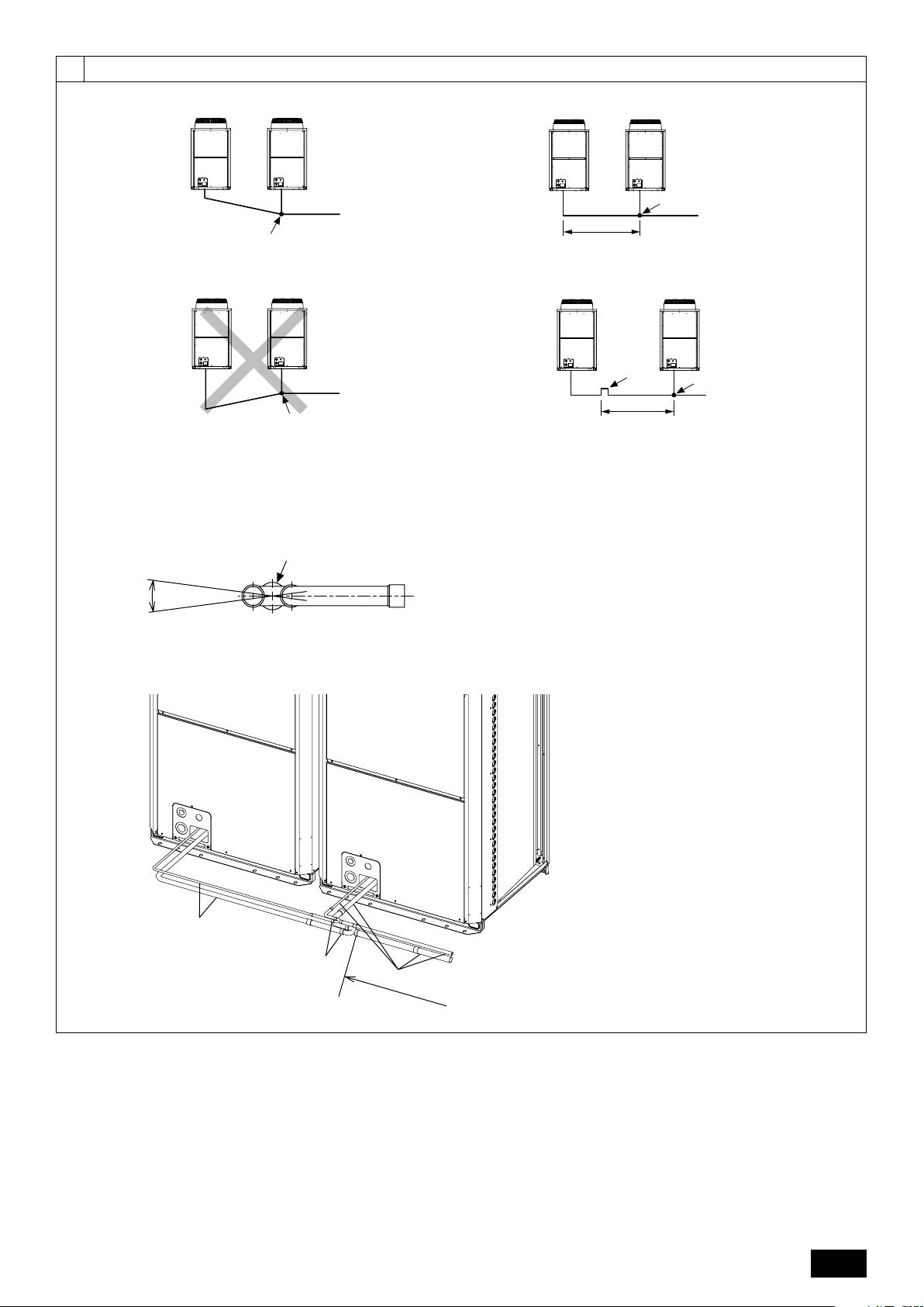
[Fig. 6.0.1] (P.2)
<A> Top view <B> Side view
<C> When there is little space up to an obstruction
A Front B Unit height
C Back D Air outlet guide (Procured at the site)
(1) If the distance is 300 mm or more between the rear side and the wall
(2) If the distance is 100 mm or more between the rear side and the wall
(3) If the wall height (H) of the front, rear or side exceeds the wall height
restriction
• When the height of the walls on the front, back or on the sides <H> exceeds
the wall height limit as defined here, add the height that exceeds the height
limit <h> to the figures that are marked with an asterisk.
7. Lifting method
[Fig. 7.0.1] (P.2)
• Use suspension ropes that will withstand the weight of the unit.
• When moving the unit, use a 4-point suspension, and avoid giving impacts to
the unit (Do not use 2-point suspension).
• Place protective pads on the unit where it comes in contact with the ropes to
protect the unit from being scratched.
• Set the angle of roping at 40° or less.
• Use 2 ropes that are each longer than 8 meters.
<Wall height limit> Front: Up to the unit height
Back: Up to 500 mm from the unit bottom
Side: Up to the unit height
(4) If there are obstacles at the upper part of the unit
2 In case of collective installation
[Fig. 6.0.2] (P.2)
A Front B Must be open
C Wall height (H)
• When multiple units are installed adjacent to each other, secure enough space
to allow for air circulation and walkway between groups of units as shown in
the figures on page 2.
• At least two sides must be left open.
• As with the single installation, add the height that exceeds the height limit <h>
to the figures that are marked with an asterisk.
• If there is a wall at both the front and the rear of the unit, install up to 6 units
consecutively in the side direction and provide a space of 1000 mm or more as
inlet space/passage space for each 6 units.
• Place protective padding at the corners of the product to protect the product
from scratches or dents that might be caused by the rope.
Caution:
Be very careful when carrying/moving the product.
- When installing the outdoor unit, suspend the unit at the specified location of the
unit base. Stabilize as necessary so that it does not move to the side and support
it at 4 points. If the unit is installed or suspended with 3-point support, the unit
may become unstable and fall.
DFEINLPGRRUTRCZSVSLHGPO
13
Page 14

8. Installation of unit
8.1. Installation
[Fig. 8.1.1] (P.3)
<A> Without detachable leg <B> With detachable leg
A M10 anchor bolt procured at the site. B Corner is not seated.
C Fixing bracket for the hole-in anchor bolt (3 locations to fix with screws).
D Detachable leg
• Fix unit tightly with bolts so that unit will not fall down due to earthquakes or
strong winds.
• Use concrete or an angle bracket as the foundation of unit.
• Vibration may be transmitted to the installation section and noise and vibration
may be generated from the floor and walls, depending on the installation conditions. Therefore, provide ample vibrationproofing (cushion pads, cushion
frame, etc.).
• Build the foundation in such way that the corner of the installation leg is securely supported as shown in the figure. (Fig. 8.1.1)
GB
When using a rubber isolating cushion, please ensure it is large enough to
cover the entire width of each of the unit's legs. If the corners are not firmly
seated, the installation feet may be bent.
• The projecting length of the anchor bolt should be less than 30 mm.
• Hole-in anchor bolts are not compatible with this product. However, if fixing
brackets are mounted on the 4 locations of the unit attachment part, hole-in
DFEINLPGRRUTRCZSVSLHGPO
anchor bolts can be used.
9. Refrigerant piping installation
The pipe is connected via a terminal-branch type connection in which refrigerant
piping from the outdoor unit is branched at the terminal and is connected to each
of the indoor units.
The method of pipe connection is as follows: flare connection for the indoor units,
gas pipes and liquid pipes for outdoor units, brazed connection. Note that the branched
sections are brazed.
Warning:
Always use extreme care to prevent the refrigerant gas from leaking while
using fire or flame. If the refrigerant gas comes in to contact with a flame
from any source, such as a gas stove, it breaks down and generates a poisonous gas which can cause gas poisoning. Never weld in an unventilated
room. Always conduct an inspection for gas leakage after installation of the
refrigerant piping has been completed.
Caution:
• Do not vent R410A into the atmosphere.
• R410A is a Fluorinated Greenhouse gas, covered by the Kyoto Protocol
with a Global Warming Potential (GWP) = 1975.
[Fig. 8.1.2]
A Screws
• The detachable leg can be removed at the site.
• Detaching the detachable leg
Loosen the three screws to detach the detachable leg (Two each in the front
and back).
If the base leg finish is damaged when detaching, be sure to repair at the site.
Warning:
• Be sure to install unit in a place strong enough to withstand its weight.
Any lack of strength may cause unit to fall down, resulting in a personal
injury.
•Have installation work in order to protect against strong winds and
earthquakes.
Any installation deficiency may cause unit to fall down, resulting in a
personal injury.
When building the foundation, give full attention to the floor strength, drain water
disposal <during operation, drain water flows out of the unit>, and piping and wiring routes.
Precautions when routing the pipes and wires below the unit (Without
detachable leg)
When routing the pipes and wires below the unit, be sure that the foundation and
base work do not block the base through-holes. Also make sure the foundation is
at least 100 mm high so that the piping can pass under the unit.
2 Commercially available piping often contains dust and other materials. Always
blow it clean with a dry inert gas.
3 Use care to prevent dust, water or other contaminants from entering the piping
during installation.
4 Reduce the number of bending portions as much as possible, and make bend-
ing radii as big as possible.
5 For indoor and outdoor branching, be sure to use the following twinning pipe
sets (sold separately).
6 Use a fitting if a specified refrigerant pipe has a different diameter from that of
a branching pipe.
7 Always observe the restrictions on the refrigerant piping (such as rated length,
height difference, and piping diameter) to prevent equipment failure or a decline in heating/cooling performance.
9.1. Caution
This unit uses refrigerant R410A. Follow the local regulations on materials and
pipe thickness when selecting pipes. (Refer to the table on the right.)
1 Use the following materials for refrigeration piping.
• Material: Use copper alloy seamless pipes made of phosphorus deoxidized copper. Ensure the inner and outer surfaces of the pipes are clean
and free from hazardous sulfur, oxide, dusts, shaving particles, oils, and
moisture (contamination).
• Size: Refer to item 9.2. for detailed information on refrigerant piping system.
Lower stream unit model
Less than 200 in total
CMY-Y102S-G2
Outdoor twinning kit model
Total outdoor model
RP400 ~ RP650
CMY-RP100VBK
** When using existing pipes, do not use the indoor twinning pipe set.
Lower stream unit model
More than 201 and less than
400 in total
CMY-Y102L-G2
Total outdoor model
RP700 ~ RP900
CMY-RP200VBK
Line branch Header branch
Indoor twinning pipe set model**
Lower stream unit model
More than 401 and less than
650 in total
CMY-Y202-G2
14
Lower stream unit model
More than 651 in total
CMY-Y302-G2
4 branching
CMY-Y104-G
8 branching
CMY-Y108-G
10 branching
10 branching
CMY-Y1010-G
CMY-Y1010-G
Page 15

8 Branching cannot be made after header branching (corresponding parts are
marked with
in the diagram below).
To the outdoor unit
To the outdoor unit
CAP
9 Either a lack or an excess of refrigerant causes the unit to make an emergency
stop. Charge the system with an appropriate amount of refrigerant. When servicing, always check the notes concerning pipe length and amount of additional
refrigerant at both locations, the refrigerant volume calculation table on the
back of the service panel and the additional refrigerant section on the labels
for the combined number of indoor units (Refer to item 9.2. for detailed information on refrigerant piping system).
0 Be sure to charge the system using liquid refrigerant.
A Never use refrigerant to perform an air purge. Always evacuate using a
vacuum pump.
B Always insulate the piping properly. Insufficient insulation will result in a de-
cline in heating/cooling performance, water drops from condensation and other
such problems (Refer to item 10.4 for thermal insulation of refrigerant piping).
C When connecting the refrigerant piping, make sure the valve of the outdoor
unit is completely closed (the factory setting) and do not operate it until the
refrigerant piping for the outdoor and indoor units has been connected, a refrigerant leakage test has been performed and the evacuation process has
been completed.
D Braze only with non-oxide brazing material for piping. Failure to do so
may damage the compressor. Be sure to perform the non-oxidation brazing with a nitrogen purge.
Do not use any commercially available anti-oxidizing agent since it may
cause pipe corrosion and degrading of the refrigerant oil.
Please contact Mitsubishi Electric for more details.
(Refer to item 10.2. for details of the piping connection and valve operation)
E Never perform outdoor unit piping connection work when it is raining.
Warning:
When installing and moving the unit, do not charge the system with any
other refrigerant other than the refrigerant specified on the unit.
- Mixing of a different refrigerant, air, etc. may cause the refrigerant cycle to malfunction and may result in severe damage.
Caution:
• Use a vacuum pump with a reverse flow check valve.
- If the vacuum pump does not have a reverse flow check valve, the vacuum
pump oil may flow back into the refrigerant cycle and cause deterioration of
the refrigerator oil.
• Do not use the tools shown below used with conventional refrigerant.
(Gauge manifold, charge hose, gas leak detector, check valve, refrigerant charge base, vacuum gauge, refrigerant recovery equipment)
- Mixing of conventional refrigerant and refrigerator oil may cause the refrig-
erator oil to deteriorate.
- Mixing of water will cause the refrigerator oil to deteriorate.
- R410A refrigerant does not contain any chlorine. Therefore, gas leak detec-
tors for conventional refrigerants will not react to it.
• Manage the tools used for R410A more carefully than normal.
- If dust, dirt, or water gets in the refrigerant cycle, the refrigerator oil will deteriorate.
• Store the piping to be used during installation indoors and keep both
ends of the piping sealed until just before brazing.
- If dust, dirt, or water gets into the refrigerant cycle, the oil will deteriorate and
the compressor may fail.
• Do not use a charging cylinder.
- Using a charging cylinder may cause the refrigerant to deteriorate.
• Do not use special detergents for washing piping.
9.2. Refrigerant piping system
Connection example
[Fig. 9.2.1] (P.3, 4)
Å Outdoor model ı Liquid pipe
Ç Gas pipe Î Total capacity of indoor units
‰ Model number Ï Downstream unit model total
Ì Joint Ó The 1st branch of P450 ~ P650
¬ The 1st branch of P700, P750, P800
Ô 4-Branching header (Downstream unit model total 200)
8-Branching header (Downstream unit model total 400)
Ò 10-Branching header (Downstream unit model total 650)
˜ Outdoor twinning kit
A Outdoor unit B First branch
C Indoor unit D Cap
E Outdoor twinning kit
*1 The pipe sizes listed in columns A1 to A3 in this table correspond to the sizes for
the models listed in the unit 1, 2, and 3 columns. When the order of the models for
unit 1, 2, and 3 change, make sure to use the appropriate pipe size.
*2 ø25.4 for R22
Precautions for outdoor unit combinations
Refer to [Fig. 9.2.2] for the positioning of twinning pipes.
[Fig. 9.2.2] (P.5)
<A> Make sure the pipes from the twinning pipe to the outdoor unit are sloped
downwards (towards the twinning pipes).
<B> When the piping on the outdoor unit side (from the twinning pipe) exceeds 2 m,
ensure a trap (gas pipe only) within 2 m. Make sure the height of the trap is 200
mm or more.
If there is no trap, oil can accumulate inside the pipe, causing a shortage of oil
and may damage the compressor.
<C> Slope of twinning pipes
Make sure the slope of the twinning pipes are at an angle within ±15° to the
ground.
If the slope exceeds the specified angle, the unit may be damaged.
<D> Pipe connection example
A Downward slope B Upward slope
C Indoor unit D Tr ap (gas pipe only)
E Within 2 m F Twinning pipe
G Slope of the twinning pipes are at an angle within ±15° to the ground
H Pipes on site I Twinning kit
J Straight run of pipe that is 500 mm or more
Caution:
• Do not install traps other than the ones between outdoor units described
on a separate sheet to prevent oil backflow and compressor start-up failure.
• Do not install solenoid valves to prevent oil backflow and compressor
start-up failure.
• Do not install a sight glass because it may show improper refrigerant
flow.
If a sight glass is installed, inexperienced technicians that use the glass
may overcharge the refrigerant.
GB
DFEINLPGRRUTRCZSVSLHGPO
10. Additional refrigerant charge
At the time of shipping, the outdoor unit is charged with refrigerant.
This charge does not include the amount needed for extended piping and additional
charging of each refrigerant line will be required on site. In order that future servicing may be properly provided, always keep a record of the size and length of
each refrigerant line and the amount of additional charge by writing it in the space
provided on the outdoor unit.
10.1. Calculation of additional refrigerant
charge
• Calculate the amount of additional charge based on the length of the piping
extension and the size of the refrigerant line.
• Use the table to the right as a guide to calculating the amount of additional
charging and charge the system accordingly.
• If the calculation results in a fraction of less than 0.1 kg, round up to the next
0.1 kg. For example, if the result of the calculation was 11.38 kg, round the
result up to 11.4 kg.
<Additional Charge>
Additional
refrigerant charge
(kg)
Liquid pipe size
Total length of
=++
ø19.05 × 0.29
(m) × 0.29 (kg/m)
Liquid pipe size
Total length of
+++ α
ø9.52 × 0.06
(m) × 0.06 (kg/m)
Liquid pipe size
Total length of
ø15.88 × 0.2
(m) × 0.2 (kg/m)
Liquid pipe size
Total length of
ø6.35 × 0.024
(m) × 0.024 (kg/m)
Liquid pipe size
Total length of
ø12.7 × 0.12
(m) × 0.12 (kg/m)
15
Page 16

<Example>
Indoor 1: 125 A: ø15.88 40 m a: ø9.52 10 m
2: 100 B: ø12.7 10 m b: ø9.52 5 m
3: 40 C: ø12.7 15 m c: ø6.35 10 m
4: 32 D: ø12.7 10 m d: ø6.35 10 m
5: 63 e: ø9.52 10 m
The total length of each liquid line is as follows:
ø15.88: A = 40 = 40 m
ø12.7: B + C + D = 10 + 15 + 10 = 35 m
ø9.52: a + b + e = 10 + 5 + 10 = 25 m
ø6.35: c + d = 10 + 10 = 20 m
Therefore,
<Calculation example>
Additional refrigerant charge
= 40 × 0.2 + 35 × 0.12 + 25 × 0.06 + 20 × 0.024 + 3.5 = 17.7 kg
Value of α
Total capacity of connecting indoor units α
GB
DFEINLPGRRUTRCZSVSLHGPO
Models ~ 80 2.0 kg
Models 81 ~ 160 2.5 kg
Models 161~ 330 3.0 kg
Models 331~ 390 3.5 kg
Models 391~ 480 4.5 kg
Models 481~ 630 5.0 kg
Models 631~ 710 6.0 kg
Models 711~ 800 8.0 kg
Models 801~ 890 9.0 kg
Models 891~1070 10.0 kg
Models 1071 ~ 12.0 kg
At the
conditions
below:
10.2. Precautions concerning piping connec-
tion and valve operation
• Conduct piping connection and valve operation accurately and carefully.
• Removing the pinched connecting pipe
When shipped, a pinched connecting pipe is attached to the on-site liquid and
gas valves to prevent gas leakage.
Ta ke the following steps 1 through 4 to remove the pinched connecting pipe
before connecting refrigerant pipes to the outdoor unit.
1 Check that the refrigerant service valve is fully closed (turned clockwise all
the way).
2 Connect a charging hose to the service port on the liquid/gas refrigerant
service valve, and extract the gas in the pipe section between the refrigerant service valve and the pinched connecting pipe (Tightening torque
12 N·m).
3 After vacuuming gas from the pinched connecting pipe, sever the pinched
connecting pipe at the location shown in [Fig.10.2.1] and drain the
refrigerant.
4 After completing 2 and 3 heat the brazed section to remove the pinched
connecting pipe.
[Fig. 10.2.1] (P.6)
<A> Refrigerant service valve (liquid side/brazed type)
<B> Refrigerant service valve (gas side/brazed type)
A Shaft
Fully closed at the factory, when connecting the piping, and when vacuuming.
Open fully after these operations are completed.
<When opening>
• Turn the shaft counterclockwise with a hexagonal wrench.
• Turn around the shaft until it stops.
<When closing>
• Turn the shaft clockwise with a hexagonal wrench.
• Turn around the shaft until it stops.
B Service port
Available for gas venting of the pinched connecting pipe, or vacuuming in the
refrigerant pipes on the site.
(Tightening torque 12 N·m)
C Cap
Remove the cap before operating the shaft. Be sure to return it to the original
position after completing the operation.
D Pinched connecting pipe severing portion
E Pinched connecting pipe brazing portion
Warning:
• The section of the pipe on the unit between the two refrigerant service
valves is filled with gas. Extract the gas in the above-mentioned pipe
section before heating the brazed section to remove the refrigerant service
valve connecting pipe.
- If the brazed section is heated without first extracting the gas, the pipe may
burst or the connecting pipe may blow off causing serious injury.
Caution:
• Place a wet towel on the refrigerant service valve before heating the brazed
section to keep the temperature of the valve from exceeding 120 ˚C.
• Direct the flame away from the wiring and metal sheets inside the unit to
prevent heat damage.
Caution:
• Do not vent R410A into the atmosphere.
• R410A is a Fluorinated Greenhouse gas, covered by the Kyoto Protocol,
with a Global Warming Potential (GWP) = 1975.
• Refrigerant pipe connection
This product includes connecting pipes for front piping and bottom post-piping.
(Refer to [Fig.10.2.2])
Check the liquid/gas piping dimensions before connecting the refrigerant pipe.
Refer to item 9.2 Refrigerant piping system for piping dimensions.
Make sure that the refrigerant pipe is not touching other refrigerants pipes, unit
panels, or base plates.
Be sure to use non-oxidative brazing when connecting pipes.
<Refrigerant piping connection examples>
[Fig.10.2.2] (P.6)
<A> Front pipe routing <B> Bottom pipe routing
<C> Included with outdoor unit
A Gas pipe (field supply required) B Liquid pipe (field supply required)
C Shape
• Front pipe routing
RP200,RP250,RP300
Liquid side
Gas side
• Bottom pipe routing
Liquid side
Gas side
*1 In the case the unit is used in combination with other outdoor units.
*2 In the case of R22.
Satisfy the minimum insertion depth in the table below when expanding on-site
piping.
• After evacuation and refrigerant charging, ensure that the handle is fully open.
If operating with the valve closed, abnormal pressure will be imparted to the
high- or low-pressure side of the refrigerant circuit, giving damage to the compressor, four-way valve, etc.
• Determine the amount of additional refrigerant charge by using the formula,
and charge refrigerant additionally through the service port after completing
piping connection work.
RP200 *1,RP250 *1
RP350
RP350 *1
RP200,RP250,
RP300,RP350 *1
RP200 *1
RP200 *2
RP250 *1,RP300 *1
RP350
RP200,RP250,RP300
RP200 *1,RP250 *1
RP350
RP350 *1
RP200,RP250,
RP300,RP350 *1
RP200 *1
RP200 *2
RP250 *1,RP300 *1
RP350
Pipe diameter (mm) Minimum insertion depth (mm)
5 or more less than 8 6
8 or more less than 12 7
12 or more less than 16 8
16 or more less than 25 10
25 or more less than 35 12
35 or more less than 45 14
Use the included connecting pipe 2 and
8 to connect.
Use the included connecting pipe 8 to con-
nect.
Use the included connecting pipe 3 and
9 to connect.
Use the included connecting pipe 9 to con-
nect.
Use the included elbow 1 and connecting
pipe 6 to connect.
Use the included elbow 1 and connecting
pipe 4 to connect.
Use the included elbow 1 to connect.
Use the included elbow 1 and connecting
pipe 5 to connect.
Use the included elbow 1 and connecting
pipe 7 to connect.
Use the included connecting pipe 2 to con-
nect.
Expand the liquid side on-site piping (ID
ø9.52)
and connect to the refrigerant service valve
piping.
Use the included connecting pipe 3 to con-
nect.
Expand the liquid side on-site piping (ID
ø12.7)
and connect to the refrigerant service valve
piping.
Use the included connecting pipe 6 to con-
nect.
Use the included connecting pipe 4 to con-
nect.
Expand the gas side on-site piping (ID
ø25.4)
and connect to the refrigerant service valve
piping.
Use the included connecting pipe 5 to con-
nect.
Use the included connecting pipe 7 to con-
nect.
16
Page 17

• After completing work, tighten the service port and cap securely so as not to
generate any gas leakage. (Refer to the table on the below for appropriate
tightening torque.)
Appropriate tightening torque:
Outer diameter of
copper pipe (mm)
ø9.52
ø12.7
ø15.88
ø19.05
ø25.4
Cap (N·m)
15
20
25
25
25
Shaft (N·m)
15
30
30
6
9
Size of hexagonal
wrench (mm)
4
4
6
8
8
Service port
(N·m)
12
Make sure to seal-off the openings for the pipe and wire retrieval.
• Small animals, rainwater, or snow entering through the openings may
10.3. Airtight test, evacuation, and refriger-
1 Airtight test
Caution:
• Keep the valve closed until refrigerant charging to the pipes to be added
on site has been completed. Opening the valve before charging the
refrigerant may cause damage to the unit.
• Do not use a leak detection additive.
[Fig. 10.2.3] (P.6)
A Example of closure materials (field supply)
B Fill the gap at the site
Make sure to seal-off the space around areas where the wires and refrigerant
pipes enter the unit to ensure that small animals, rainwater, or snow cannot enter
the unit through such openings and cause damage to the unit.
Airtight test procedure
(1) After pressurizing to the design pressure (4.15 MPa) using nitrogen gas, allow it to stand for
about one day. If the pressure does not drop, airtightness is good.
However, if the pressure drops, since the leaking point is unknown, the following bubble test
may also be performed.
(2) After the pressurization described above, spray the flare connection parts, brazed parts, and
other parts that may leak with a bubbling agent (Kyuboflex, etc.) and visually check for bubbles.
(3) After the airtight test, wipe off the bubbling agent.
Observe the following restrictions when conducting an air tightness test to prevent
negative effects on the refrigerating machine oil. Also, with nonazeotropic refrigerant (R410A), gas leakage causes the composition to change and affects performance. Therefore, perform the airtightness test cautiously.
Caution:
cause damage to the device.
ant charging
Perform with the valve of the outdoor unit closed, and pressurize the connection piping and the indoor unit from the service port provided on the valve of
the outdoor unit. (Always pressurize from both the liquid pipe and the gas pipe
service ports.)
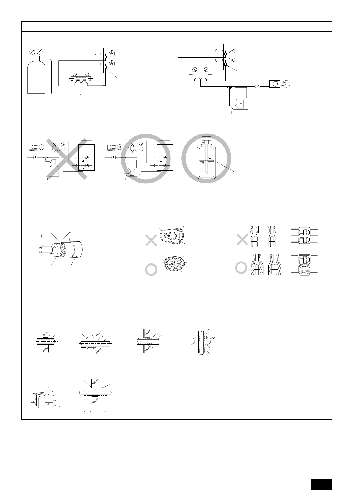
[Fig. 10.3.1] (P.7)
A Nitrogen gas B To indoor unit C System analyzer
D Low knob E Hi knob F Valve
G Liquid pipe H Gas pipe I Outdoor unit
J Service port
Restriction
• If a flammable gas or air (oxygen) is used as the pressurization
gas, it may catch fire or explode.
GB
DFEINLPGRRUTRCZSVSLHGPO
Caution:
Only use refrigerant R410A.
- The use of other refrigerants such as R22 or R407C, which contains chlorine,
will deteriorate the refrigerating machine oil or cause the compressor to malfunction.
2 Evacuation
Evacuate with the valve of the outdoor unit closed and evacuate both the connection piping and the indoor unit from the service port provided on the valve
of the outdoor unit using a vacuum pump. (Always evacuate from the service
port of both liquid pipe and gas pipe.) After the vacuum reaches 650 Pa [abs],
continue evacuation for at least one hour or more. Then, stop the vacuum
pump and leave it for 1 hour. Ensure the degree of vacuum has not increased.
(If the degree of vacuum increase is larger than 130 Pa, water might have
entered. Apply pressure to dry nitrogen gas up to 0.05 MPa and vacuum
again.) Finally, seal in with the liquid refrigerant through the liquid pipe, and
adjust the gas piping to obtain an appropriate amount of the refrigerant during
operation.
* Never perform air purging using refrigerant.
[Fig. 10.3.2] (P.7)
A System analyzer B Low knob C Hi knob
D Valve E Liquid pipe F Gas pipe
G Service port H Three-way joint I Valve
J Valve K R410A cylinder L Scale
M Vacuum pump N To indoor unit O Outdoor unit
Note:
•Always add an appropriate amount of refrigerant. Also always charge
the system with liquid refrigerant.
• Use a gauge manifold, charging hose, and other parts for the refrigerant
indicated on the unit.
• Use a graviometer. (One that can measure down to 0.1 kg.)
• Use a vacuum pump with a reverse flow check valve.
(Recommended vacuum gauge: ROBINAIR 14830A Thermistor Vacuum
Gauge)
Also use a vacuum gauge that reaches 65 Pa [abs] or below after operating for five minutes.
3 Refrigerant Charging
Since the refrigerant used with the unit is nonazerotropic, it must be charged in
the liquid state. Consequently, when charging the unit with refrigerant from a
cylinder, if the cylinder does not have a syphon pipe, charge the liquid refrigerant by turning the cylinder upside-down as shown in Fig.10.3.3. If the cylinder
has a syphon pipe like that shown in the picture on the right, the liquid refrigerant can be charged with the cylinder standing upright. Therefore, give careful
attention to the cylinder specifications. If the unit should be charged with gas
refrigerant, replace all the refrigerant with new refrigerant. Do not use the refrigerant remaining in the cylinder.
[Fig. 10.3.3] (P.7)
A Syphon pipe B
In case of the R410A cylinder having no syphon pipe.
10.4. Thermal insulation of refrigerant piping
Be sure to add insulation work to refrigerant piping by covering liquid pipe and gas
pipe separately with enough thickness heat-resistant polyethylene, so that no gap
is observed in the joint between indoor unit and insulating material, and insulating
materials themselves. When insulation work is insufficient, there is a possibility of
condensation drip, etc. Pay special attention to insulation work in the ceiling plenum.
[Fig. 10.4.1] (P.7)
A Steel wire B Piping
C Asphaltic oily mastic or asphalt D Heat insulation material A
E Outer covering B
Heat
insulation
material A
Outer
covering B
Note:
• When using polyethylene cover as covering material, asphalt roofing shall
not be required.
• No heat insulation must be provided for electric wires.
[Fig. 10.4.2] (P.7)
[Fig. 10.4.3] (P.7)
Glass fiber + Steel wire
Adhesive + Heat - resistant polyethylene foam + Adhesive tape
Indoor Vinyl tape
Floor exposed Water-proof hemp cloth + Bronze asphalt
Outdoor Water-proof hemp cloth + Zinc plate + Oily paint
A Liquid pipe B Gas pipe C Electric wire
D Finishing tape E Insulator
17
Page 18

Penetrations
[Fig. 10.4.4] (P.7)
<A> Inner wall (concealed) <B> Outer wall
<C> Outer wall (exposed) <D> Floor (waterproofing)
<E> Roof pipe shaft
<F> Penetrating portion on fire limit and boundary wall
A Sleeve B Heat insulating material
C Lagging D Caulking material
E Band F Waterproofing layer
G Sleeve with edge H Lagging material
I Mortar or other incombustible caulking
J Incombustible heat insulation material
GB
11. Wiring (For details, refer to the installation manual of each unit and controller.)
When filling a gap with mortar, cover the penetration part with steel plate so that
the insulation material will not be caved in. For this part, use incombustible materials for both insulation and covering. (Vinyl covering should not be used.)
• Insulation materials for the pipes to be added on site must meet the following
specifications:
ø6.35 to 25.4 mm
Thickness
Temperature Resistance
* Installation of pipes in a high-temperature high-humidity environment, such as
the top floor of a building, may require the use of insulation materials thicker
than the ones specified in the chart above.
* When certain specifications presented by the client must be met, ensure that
they also meet the specifications on the chart above.
10 mm min.
Pipe size
ø28.58 to 41.28 mm
15 mm min.
100°C min.
11.1. Caution
1 Follow ordinance of your governmental organization for technical standard re-
lated to electrical equipment, wiring regulations and guidance of each electric
power company.
DFEINLPGRRUTRCZSVSLHGPO
2 Wiring for control (hereinafter referred to as transmission line) shall be (5 cm
or more) apart from power source wiring so that it is not influenced by electric
noise from power source wiring (Do not insert transmission line and power
source wire in the same conduit).
3 Be sure to provide designated grounding work the to the outdoor unit.
4 Give some allowance to wiring for electrical part box of indoor and outdoor
units, because the box is sometimes removed at the time of service work.
5 Never connect the main power source to terminal block of transmission line. If
connected, electrical parts will burn out.
6 Use 2-core shield cable for transmission line. If transmission lines of different
systems are wired with the same multiplecore cable, the resultant poor transmitting and receiving will cause erroneous operations.
7 Only the transmission line specified should be connected to the terminal block
for outdoor unit transmission.
Erroneous connection does not allow the system to operate.
8 In the case of connecting with an upper class controller or to conduct group
operation in different refrigerant systems, the control line for transmission is
required between the outdoor units in different refrigerant systems.
Connect this control line between the terminal blocks for centralized control
(2-wire line with no polarity).
9 Group is set by operating the remote controller.
11.2. Control box and connecting position of
wiring
1 Outdoor unit
1. Remove the front panel of the control box by removing the 4 screws and push-
ing it up a little before pulling it out.
2. Connect the indoor - outdoor transmission line to the terminal block (TB3) for
the indoor - outdoor transmission line.
If multiple outdoor units are connected in the same refrigerant system, daisychain TB3 (M1, M2,
outdoor transmission line for the outdoor units to TB3 (M1, M2,
only one of the outdoor units.
3. Connect the transmission lines for centralized control (between the centralized
control system and the outdoor unit of different refrigerant systems) to the
terminal block for centralized control (TB7). If the multiple outdoor units are
connected to the same refrigerant system, daisy-chain TB7 (M1, M2, S Terminal) on the outdoor units in the same refrigerant system. (*1)
*1: If TB7 on the outdoor unit in the same refrigerant system is not daisy-
chained, connect the transmission line for centralized control to TB7 on
the OC (*2). If the OC is out of order, or if the centralized control is being
conducted during the power supply shut-off, daisy-chain TB7 on the OC,
OS1, and OS2 (In the case that the outdoor unit whose power supply
connector CN41 on the control board has been replaced with CN40 is out
of order or the power is shut-off, centralized control will not be conducted
even when TB7 is daisy-chained).
*2: OC, OS1, and OS2 of the outdoor units in the same refrigerant system are
automatically identified. They are identified as OC, OS1, and OS2 in descending order of capacity (If the capacity is the same, they will be in
ascending order of their address number).
Terminal) on the outdoor units. Connect the indoor -
Te r minal) of
4. In the case of indoor-outdoor transmission line, connect the shield ground to
the grounding terminal (
control, connect it to the shield terminal (S) on the terminal block for centralized control (TB7). Furthermore, in the case of the outdoor units whose power
supply connector CN41 is replaced with CN40, short circuit the shield terminal
(S) and the grounding terminal (
5. Fix the connected wires securely in place with the cable strap at the bottom of
the terminal block. External force applied to the terminal block may damage it
resulting in a short circuit, ground fault, or a fire.
[Fig. 11.2.1] (P.8)
A Po wer source B Tr ansmission line
C Earth screw
[Fig. 11.2.2] (P.8)
A Cable strap B Po wer source line
C Tr ansmission line
2 Conduit tube installation
• Open by hammering the knockout holes for the conduit tube located on the
base and the bottom part of the front panel.
• When installing the conduit tube directly through the knockout holes, remove
the burr and protect the tube with masking tape.
• Use the conduit tube to narrow down the opening if there is a possibility of
small animals entering the unit.
). In the case of transmission lines for centralized
) in addition to the above.
11.3. Wiring transmission cables
1 Types of control cables
1. Wiring transmission cables
•Types of transmission cables: Shielding wire CVVS, CPEVS or MVVS
• Cable diameter: More than 1.25 mm
• Maximum wiring length: Within 200 m
• Maximum length of transmission lines for centralized control and indoor/outdoor transmission lines (Maximum length via outdoor units): 500 m MAX
The maximum length of the wiring between power supply unit for transmission
lines (on the transmission lines for centralized control) and each outdoor unit
and system controller is 200 m.
2. Remote control cables
• M-NET Remote Controller
Kind of remote control cable
Cable diameter
Remarks
• MA Remote Controller
Kind of remote control cable
Cable diameter
Remarks
* Connected with simple remote controller.
2
Sheathed 2-core cable (unshielded) CVV
0.3 to 1.25 mm
When 10 m is exceeded, use cable with the
same specifications as 1. Wiring transmission
cables.
Sheathed 2-core cable (unshielded) CVV
0.3 to 1.25 mm
Within 200 m
2
(0.75 to 1.25 mm2)*
2
(0.75 to 1.25 mm2)*
18
Page 19
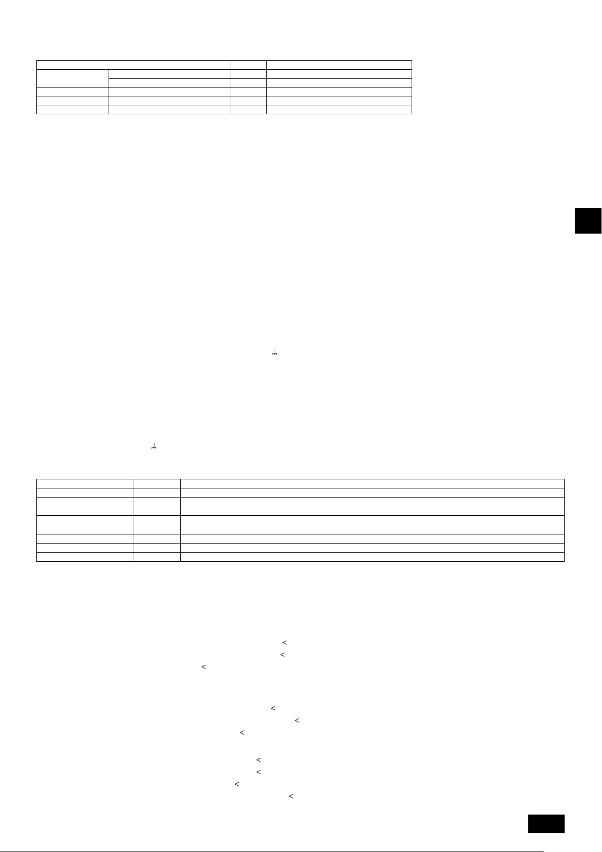
2 Wiring examples
• Controller name, symbol and allowable number of controllers.
Name Code Possible unit connections
Outdoor unit
Indoor unit
Remote controller
Other
*1 A transmission booster (RP) may be required depending on the number of connected indoor unit controllers.
*2 OC, OS1, and OS2 of the outdoor units in the same refrigerant system are automatically identified. They are identified as OC, OS1, and OS2 in descending order of
capacity. (If the capacity is the same, they will be in ascending order of their address number.)
Main unit
Sub unit
Indoor unit controller
Remote controller (*1)
Tr ansmission booster unit
OC
OS1, OS2
IC
RC
RP
– (*2)
– (*2)
1 to 32 units per 1 OC (*1)
2 units maximum per group
0 to 1 unit per 1 OC (*1)
Example of a group operation system with multiple outdoor units (Shielding wires and address setting are
necessary.)
<Examples of transmission cable wiring>
[Fig. 11.3.1] M-NET Remote Controller (P.8)
*1: When the power supply unit is not connected to the transmission line for centralized control, disconnect the male power supply connector (CN41) from ONE
outdoor unit in the system and connect it to CN40.
*2: If a system controller is used, set SW2-1 on all of the outdoor units to ON.
[Fig. 11.3.2] MA Remote Controller (P.9)
<A> Change the jumper connector from CN41 to CN40
<B> SW2-1:ON
<C> Keep the jumper connector on CN41
A Group 1 B Group 3 C Group 5 D Shielded wire E Sub remote controller
( ) Address
[Fig. 11.3.3] Combination of outdoor units and transmission booster unit (P.9)
<Wiring Method and Address Settings>
a. Always use shielded wire when making connections between the outdoor unit (OC) and the indoor unit (IC), as well for all OC-OC, OC-OS, OS-OS, and IC-IC wiring
intervals.
b. Use feed wiring to connect terminals M1 and M2 and the earth terminal
and terminal S on the transmission line block of the indoor unit (IC). For OC and OS, connect TB3 to TB3.
c. Connect terminals 1 (M1) and 2 (M2) on the transmission line terminal block of the indoor unit (IC) that has the most recent address within the same group to the terminal
block on the remote controller (RC).
d. Connect together terminals M1, M2 and terminal S on the terminal block for central control (TB7) for the outdoor unit in a different refrigerant system (OC). For OC and
OS in the same refrigerant system, connect TB7 to TB7.
e. When the power supply unit is not installed on the central control transmission line, change the jumper connector on the control board from CN41 to CN40 on only one
outdoor unit in the system.
f. Connect the terminal S on the terminal block for central control (TB7) for the outdoor unit (OC) for the unit into which the jumper connector was inserted into CN40 in the
step above to the earth terminal
g. Set the address setting switch as follows.
*To set the outdoor unit address to 100, the outdoor address setting switch must be set to 50.
Unit Range Setting Method
Indoor unit (Main) 01 to 50 Use the most recent address within the same group of indoor units
Indoor unit (Sub) 01 to 50
Outdoor Unit (OC, OS) 51 to 100
M-NET R/C (Main) 101 to 150 Set at an IC (Main) address within the same group plus 100
M-NET R/C (Sub) 151 to 200 Set at an IC (Main) address within the same group plus 150
MA R/C – Unnecessary address setting (Necessary main/sub setting)
h. The group setting operations among the multiple indoor units is done by the remote controller (RC) after the electrical power has been turned on.
i. When the centralized remote controller is connected to the system, set centralized control switches (SW2-1) on control boards in all outdoor units (OC, OS) to “ON”.
*1 OC, OS1, and OS2 of the outdoor units in the same refrigerant system are automatically identified. They are identified as OC, OS1, and OS2 in descending order of
capacity (If the capacity is the same, they are identified in the ascending order of their address number).
in the electrical component box.
Use an address, other than that of the IC (Main) from among the units within the same group of indoor units. This must be
in sequence with the IC (Main)
Set the addresses of the outdoor units in the same refrigerant system in the order of sequential number. OC, OS1, and
OS2 are automatically identified. (*1)
on the transmission line terminal block (TB3) of each outdoor unit (OC) to terminals M1, M2
GB
DFEINLPGRRUTRCZSVSLHGPO
<Permissible Lengths>
1 M-NET Remote controller
• Max length via outdoor units: L
• Max transmission cable length: L
• Remote controller cable length: r
2 MA Remote controller
• Max length via outdoor unit (M-NET cable): L
• Max transmission cable length (M-NET cable): L
• Remote controller cable length: c
3 Transmission booster
• Max transmission cable length (M-NET cable): 1 L
1+L2+L3+L4 and L1+L2+L3+L5 and L1+L2+L6
1 and L3+L4 and L3+L5 and L6 and L2+L6
1, r2, r3, r4
If the length exceeds 10 m, use a 1.25 mm
maximum length and overall length.
1+L2+L3+L4 and L1+L2+L6
1 and L3+L4 and L6 and L2+L6
1+c2 and c1+c2+c3+c4
2 L
3 L
4 L
10 m (0.3 to 1.25 mm2)
=
200 m (0.3 to 1.25 mm2)
=
1+L2+L3+L5+L6
1+L2+L3+L5+L7
1+L2+L4
6+L5+L3+L4, L4+L3+L5+L7
200 m (1.25 mm2)
=
200 m (1.25 mm2)
=
200 m (1.25 mm2)
=
500 m (1.25 mm2 or more)
=
200 m (1.25 mm2 or more)
=
2
shielded wire. The length of this section (L8) should be included in the calculation of the
500 m (1.25 mm2 or more)
=
200 m (1.25 mm2 or more)
=
200 m (1.25 mm2)
=
19
Page 20

• Remote controller cable length: r1, r2 = 10 m (0.3 to 1.25 mm2)
If the length exceeds 10 m, use 1.25 mm
2
shielded cable and calculate the length of that portion (L4 and L7) as within the total extended
length and the longest remote length.
11.4. Wiring of main power supply and equipment capacity
Schematic Drawing of Wiring (Example)
[Fig. 11.4.1] (P.9)
A Switch (Breakers for wiring and current leakage) B Breakers for current leakage C Outdoor unit
D Pull box E Indoor unit
Thickness of wire for main power supply, capacities of the switch and system impedance
Minimum wire thickness (mm
Main cable
4
4
4
6
1.5
2.5
4.0
Branch Capacity Fuse
-
-
-
-
1.5
2.5
4.0
GB
Outdoor unit
Total operating
current of the
indoor unit
Model
PUHY-RP200YJM-A
PUHY-RP250YJM-A
PUHY-RP300YJM-A
PUHY-RP350YJM-A
16A or less
25A or less
32A or less
*1: Meets technical requirements of IEC61000-3-3
1. Use dedicated power supplies for the outdoor unit and indoor unit. Ensure OC and OS are wired individually.
2. Bear in mind ambient conditions (ambient temperature,direct sunlight, rain water,etc.) when proceeding with the wiring and connections.
3. The wire size is the minimum value for metal conduit wiring. If the voltage drops, use a wire that is one rank thicker in diameter.
Make sure the power-supply voltage does not drop more than 10%.
DFEINLPGRRUTRCZSVSLHGPO
4. Specific wiring requirements should adhere to the wiring regulations of the region.
5. Power supply cords of parts of appliances for outdoor use shall not be lighter than polychloroprene sheathed flexible cord (design 245 IEC57). For example,
use wiring such as YZW.
6. A switch with at least 3 mm contact separation in each pole shall be provided by the Air Conditioner installer.
Warning:
• Be sure to use specified wires for connections and ensure no external force is imparted to terminal connections. If connections are not fixed firmly, heating
or fire may result.
• Be sure to use the appropriate type of overcurrent protection switch. Note that generated overcurrent may include some amount of direct current.
Caution:
• Some installation sites may require attachment of an earth leakage breaker for the inverter. If no earth leakage breaker is installed, there is a danger of
electric shock.
• Do not use anything other than a breaker and fuse with the correct capacity. Using a fuse or wire of too large capacity may cause malfunction or fire.
Note:
• This device is intended for the connection to a power supply system with a maximum permissible system impedance shown in the above table at the
interface point (power service box) of the user’s supply.
• The user must ensure that this device is connected only to a power supply system which fulfils the requirement above.
If necessary, the user can ask the public power supply company for the system impedance at the interface point.
• This equipment complies with IEC 61000-3-12 provided that the short-circuit power S
user’s supply and the public system. It is the responsibility of the installer or user of the equipment to ensure, by consultation with the distribution network
operator if necessary, that the equipment is connected only to a supply with a short-circuit power S
1.5
2.5
4.0
2
)
Breaker for current leakage
4
30A 100mA 0.1sec or less
4
30A 100mA 0.1sec or less
4
30A 100mA 0.1sec or less
6
40A 100mA 0.1sec or less
20A 100mA 0.1sec or less
30A 100mA 0.1sec or less
40A 100mA 0.1sec or less
Local swtich (A)
25
25
32
40
16
25
32
is greater than or equal to S
SC
greater than or equal to S
SC
Breaker for
wiring (A) NFBGround
25
25
32
40
16
25
32
(*2) at the interface point between the
SC
30
30
30
40
20
30
40
SC
Max. Permissive
System impedance
0.26Ω
(apply to IEC61000-3-3)
(apply to IEC61000-3-3)
(apply to IEC61000-3-3)
(*2).
*1
*1
*1
S
(*2)
SC
Model S
SC
PUHY-RP200YJM 1.25
PUHY-RP250YJM 1.54
PUHY-RP300YJM 1.75
PUHY-RP350YJM 2.31
(MVA)
20
Page 21
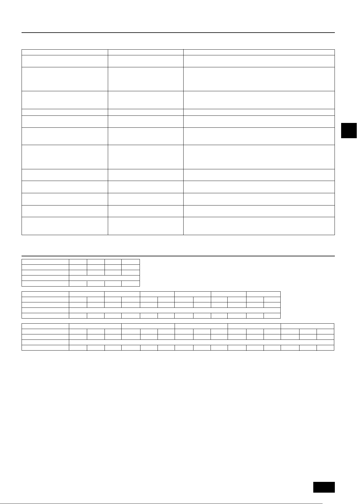
12.Test run
12.1. The following phenomena do not represent faults.
Indoor unit does not perform cooling (heating)
Phenomenon
operation.
The auto vane rotates and begins to blow air
horizontally.
Fan setting changes during heating.
Fan stops during heating operation.
Fan does not stop while operation has been
stopped.
No setting of fan while start SW has been
turned on.
Indoor unit remote controller shows “H0” or
“PLEASE WAIT” indicator for about five minutes when turning ON universal power supply.
Drain pump does not stop when unit is
stopped.
Drain pump continues to operate while unit
has been stopped.
Indoor unit emits noise when switching from
heating to cooling and vice versa.
Immediately after startup, the indoor unit
emits the sound of the refrigerant flow.
Warm air comes from an indoor unit that is
not performing a heating operation.
Display of remote controller
“Cooling (heating)” flashes
Normal display
Normal display
Defrost display
No lighting
Heat ready
“H0” or “PLEASE WAIT” flashes
Light out
Normal display
Normal display
Normal display
When another indoor unit is performing the heating (cooling) operation, the cool-
Cause
ing (heating) operation is not performed.
If air has been blowing downward for 1 hour during cooling, the unit may
automatically change to horizontal blowing with the control operation of the auto
vane. During defrosting or immediately after heating start-up/shut-down, the auto
vane automatically rotates to blow air horizontally for a short period of time.
Ultra-low speed operation is commenced at thermostat OFF.
Light air automatically changes over to set value by time or piping temperature at
thermostat ON.
The fan is to stop during defrosting.
The fan is set to run for 1 minute after stopping to exhaust residual heat (only in
heating).
Ultra low-speed operation for 5 minutes after SW ON or until piping temperature
becomes 35°C, low speed operation for 2 minutes thereafter, and then set notch
is commenced (Hot adjust control).
The system is being started up.
Operate remote controller again after “H0” or “PLEASE WAIT” disappear.
After cooling operation stops, the unit continues to operate drain pump for three
minutes and then stops it.
Unit continues to operate drain pump if drainage is generated, even during a
stop.
This is a switching sound of the refrigerant circuit and does not imply a problem.
Unstable flow of the refrigerant emits a sound. This is temporary and does not
imply a problem.
The LEV is slightly open to prevent refrigerant, of the indoor unit that is not
performing the heating operation, from being liquefied. This does not imply a
problem.
GB
DFEINLPGRRUTRCZSVSLHGPO
13. Information on rating plate
Model
Unit combination
Refrigerant
Allowable pressure (Ps)
Net weight
Model
Unit combination
Refrigerant
Allowable pressure (Ps)
Net weight
Model
Unit combination
Refrigerant
Allowable pressure (Ps)
Net weight
MANUFACTURER: MITSUBISHI ELECTRIC CORPORATION
AIR-CONDITIONING & REFRIGERATION SYSTEMS WORKS 5-66, TEBIRA, 6-CHOME, WAKAYAMA CITY, JAPAN
RP250
RP200
6.5
230kg
RP200
6.5
230kg
RP200
6.5
230kg
-
-
9.0
HP: 4.15MPa , LP: 2.21MPa
255kg
RP400 RP450 RP500 RP550
RP200
6.5
230kg
RP700 RP750 RP800 RP850 RP900
RP250
9.0
255kg
RP300
-
9.0
255kg
RP200
6.5
230kg
RP250
9.0
255kg
RP350
9.0
255kg
RP250
9.0
255kg
RP250
9.0
255kg
-
RP250
RP250
9.0
HP: 4.15MPa , LP: 2.21MPa
255kg
RP250
RP250
9.0
255kg
RP250
9.0
9.0
255kg
255kg
RP250
9.0
9.0
HP: 4.15MPa , LP: 2.21MPa
255kg
255kg
RP300
9.0
255kg
RP250
9.0
255kg
RP600 RP650
RP300
RP300
9.0
9.0
255kg
RP300
255kg
9.0
255kg
RP250
9.0
255kg
RP300
9.0
255kg
RP300
9.0
255kg
RP350
9.0
255kg
RP300
9.0
255kg
RP300
9.0
255kg
RP300
9.0
255kg
RP300
9.0
255kg
21
Page 22

Inhalt
1. Sicherheitsvorkehrungen ........................................................................... 22
1.1. Vor Beginn der Installations- und Elektroarbeiten ..................... 22
1.2. Vorkehrungen für Geräte, die R410A-Kältemittel verwenden ... 23
1.3. Vor der Installation ....................................................................23
1.4. Vor Beginn der Installations- (Standortwechsel) und
Elektroarbeiten .......................................................................... 23
1.5. Vor dem Start des Testbetriebs .................................................23
2. Produktinformationen ................................................................................. 24
3. Kombination von Außeneinheiten .............................................................. 24
4. Technische Daten ...................................................................................... 24
5. Bestätigung von Anschlussteilen ............................................................... 25
6. Um das Gerät erforderlicher Freiraum ....................................................... 25
7. Hebemethode ............................................................................................ 25
8. Installieren des Geräts ............................................................................... 26
8.1. Installation ................................................................................. 26
9. Installieren der Kältemittelleitungen ........................................................... 26
9.1. Vorsicht ..................................................................................... 26
9.2. Das Kältemittelrohrleitungssystem ........................................... 27
1. Sicherheitsvorkehrungen
D
1.1. Vor Beginn der Installations- und
Elektroarbeiten
X
Lesen Sie vor dem Installieren des Geräts unbedingt alle im
Abschnitt "Sicherheitsvorkehrungen" beschriebene Hinweise.
X
Der Abschnitt "Sicherheitsvorkehrungen" verweist auf sehr
wichtige Sicherheitsaspekte. Achten Sie auf ihre Befolgung.
In diesem Text verwendete Symbole
Achtung:
Beschreibt Vorkehrungen, die getroffen werden sollten, um einer
Verletzungs- oder Lebensgefahr des Anwenders vorzubeugen.
Vorsicht:
Beschreibt Vorkehrungen, die getroffen werden sollten, um einer
Beschädigung des Geräts vorzubeugen.
In den Illustrationen verwendete Symbole
: Verweist auf einen Vorgang, der vermieden werden muss.
: Verweist auf wichtige Anleitungen, die befolgt werden müssen.
: Verweist auf ein Teil, das geerdet sein muss.
: Stromschlaggefahr. (Dieses Symbol ist am Etikett des Hauptgeräts
angebracht.) <Farbe: Gelb>
Achtung:
Lesen Sie die am Hauptgerät angebrachten Etiketten sorgfältig.
ACHTUNG HOCHSPANNUNG:
Die Steuerung enthält unter Hochspannung stehende Teile.
•
Achten Sie darauf, dass die Frontverkleidung der Steuerung beim Öffnen
•
oder Schließen nicht mit internen Komponenten in Kontakt kommt.
Schalten Sie vor der Inspektion des Inneren der Steuerung die
•
Stromversorgung aus, lassen Sie das Gerät mindestens 10 Minuten
ausgeschaltet und vergewissern Sie sich, dass die Spannung zwischen FT-P
und FT-N an der INV-Platine auf 20 V Gleichstrom oder weniger abgefallen ist
(Die elektrische Entladung nach dem Ausschalten der
Stromversorgung dauert ca. 10 Minuten.)
Achtung:
Beauftragen Sie den Händler oder eine autorisierte Fachkraft mit der
•
Installation des Klimageräts.
- Eine unsachgemäße Installation durch den Anwender kann in
Wasserleckage, Stromschlag oder Feuer resultieren.
Dieses Gerät ist nicht für die Verwendung durch Personen
•
(einschließlich Kinder) mit verminderten physischen, Wahrnehmungsoder geistigen Fähigkeiten oder mit mangelnder Erfahrung oder
mangelnden Kenntnissen vorgesehen, es sei denn, sie wurden von
einer für ihre Sicherheit verantwortliche Person in der Verwendung des
Geräts überwacht bzw. in diese eingewiesen.
Installieren Sie das Gerät an einem Ort mit einer für sein Gewicht
•
ausreichenden Tragkraft.
- Andernfalls könnte das Gerät herunterfallen und Verletzungen oder
Geräteschäden verursachen.
Verwenden Sie zur Verkabelung die angegebenen Kabel. Schließen Sie
•
sie sicher an, so dass externe auf das Kabel aufgebrachte Kräfte nicht
auf die Anschlüsse übertragen werden.
- Bei einem inkorrekten Anschluss oder Befestigen kann Hitze entstehen
und ein Brand verursacht werden.
Treffen Sie Vorkehrungen zum Schutz vor starkem Wind und Erdbeben
•
und installieren Sie das Gerät am angegebenen Ort.
- Eine unsachgemäße Installation könnte im Herunterfallen des Geräts und
in Verletzungen oder Geräteschäden resultieren.
10. Nachfüllen von Kältemittel ......................................................................... 27
10.1. Berechnen der Kältemittelnachfüllmenge ................................. 27
10.2. Vorkehrungen bezüglich Rohrleitungsanschluss und
Ventilbedienung ......................................................................... 28
10.3. Luftdichtigkeitstest, Entlüftung und Kältemittelauffüllung .......... 29
10.4. Thermoisolierung der Kältemittelleitungen ................................ 29
11. Verkabelung (Weitere Details sind im Installationshandbuch der
jeweiligen Geräte und Steuerungen enthalten.) ......................................... 30
11.1. Vorsicht ..................................................................................... 30
11.2. Steuerkasten und Kabelanschlusspositionen ........................... 30
11.3. Verlegen der Übertragungskabel .............................................. 30
11.4. Verkabelung der Hauptstromversorgung und
12. Testbetrieb .................................................................................................. 33
13. Informationen zur Nennwertplakette........................................................... 33
Verwenden Sie stets Filter und anderes von Mitsubishi Electric spezifi ziertes Zubehör.
•
- Beauftragen Sie eine autorisierte Fachkraft mit der Installation des
Versuchen Sie nie, das Gerät zu reparieren. Wenden Sie sich zur
•
Reparatur des Klimageräts stets an den Händler.
- Eine unsachgemäße Reparatur des Geräts kann in Wasserleckage,
Falls das Stromversorgungskabel beschädigt ist, muss es zur
•
Vermeidung von Gefahren durch den Hersteller, dessen Serviceagentur
oder ähnlich qualifi zierte Personen ausgetauscht werden.
Berühren Sie die Wärmetauscherrippen nicht.
•
- Eine unsachgemäße Handhabung kann in Verletzungen resultieren.
Lüften Sie den Raum, falls während der Installationsarbeiten Kältegas austritt.
•
- Wenn das Kältegas mit einer offenen Flamme in Kontakt kommt, werden
Installieren Sie das Klimagerät gemäß dieses Installationshandbuchs.
•
- Eine unsachgemäße Installation des Geräts kann in Wasserleckage,
Alle Elektroarbeiten müssen von einem lizenzierten Elektriker gemäß dem
•
"Technischen Standard für Elektroanlagen" und den "Verkabelungsvorschriften für
Innenräume" sowie den in diesem Handbuch gegebenen Anleitungen ausgeführt
werden. Des Weiteren ist eine geeignete Stromversorgung zu verwenden.
- Eine unzureichende Kapazität der Stromversorgung oder inkorrekt
Bringen Sie die Abdeckung (Tafel) des Außengeräts sicher an.
•
- Falls die Anschlussabdeckung (Tafel) nicht korrekt installiert ist, kann
•
Wenn das Klimagerät installiert oder an einen anderen Ort transportiert
wird, darf es mit keinem anderen als dem am Gerät angegebenen
Kältemittel gefüllt werden.
- Falls ein anderes Kältemittel oder Luft mit dem Originalkältemittel gemischt
•
Bei der Installation des Klimageräts in einem kleinen Raum
müssen Vorkehrungen getroffen werden, um ein Überschreiten der
Sicherheitsgrenze der Kältemittelkonzentration im Fall einer Leckage
von Kältemittel zu verhindern.
- Holen Sie den Rat des Händlers bezüglich angemessener Maßnahmen zur
.
Holen Sie beim Transportieren oder der Neuinstallation des Klimageräts
•
den Rat des Händlers oder einer autorisierten Fachkraft ein.
- Eine unsachgemäße Installation des Klimageräts kann in Wasserleckage,
•
Überzeugen Sie sich nach Abschluss der Installationsarbeiten, dass
kein Kältegas austritt.
-
Rekonstruieren oder verändern Sie die Schutzvorrichtungen nicht.
•
- Falls der Druckschalter, Thermoschalter oder eine andere
•
Holen Sie zur Entsorgung dieses Produkts den Rat Ihres Händlers ein.
Der Installateur und Systemspezialist gewährleistet die Leckagesicherheit
•
im Einklang mit den örtlich geltenden Vorschriften bzw. Normen.
-
Tragen Sie insbesondere dem Installationsort wie zum Beispiel einem
•
Keller usw. - wo sich Kältegas ansammeln kann - Rechnung, da
Kältemittel schwerer als Luft ist.
Bei Außengeräten, die das Ansaugen von Frischluft in das Innengerät
•
zulassen, ist der Installationsort besonders sorgfältig zu wählen, da bei
ausgeschaltetem Thermostat Außenluft direkt in den Raum eindringen kann.
- Der direkte Kontakt mit Außenluft kann schädliche Auswirkungen auf
Gerätekapazität ......................................................................... 32
12.1. Bei den folgenden Erscheinungen handelt es sich nicht um
Fehler. ....................................................................................... 33
Zubehörs. Eine unsachgemäße Installation durch den Anwender kann in
Wasserleckage, Stromschlag oder Feuer resultieren.
Stromschlag oder Feuer resultieren.
giftige Gase freigesetzt.
Stromschlag oder Feuer resultieren.
ausgeführte Elektroarbeiten können in Stromschlag oder Feuer resultieren.
Staub oder Wasser in das Außengerät eindringen und in Feuer oder
Stromschlag resultieren.
wird, kann dies in einer Funktionsstörung des Kältemittelkreislaufs oder
einer Beschädigung des Geräts resultieren.
Verhinderung der Überschreitung dieser Sicherheitsgrenze ein. Bei einer
Leckage von Kältemittel und einem Überschreiten der Sicherheitsgrenze
besteht im Raum Gefahr in Folge von Sauerstoffmangel.
Stromschlag oder Feuer resultieren.
Falls Kältegas austritt und mit einem Heizlüfter, Herd, Ofen oder einer anderen
Wärmequelle in Kontakt kommt, können giftige Gase freigesetzt werden.
Schutzvorrichtung kurzgeschlossen oder gewaltsam bedient wird oder
andere als von Mitsubishi Electric angegebene Teile verwendet werden,
besteht Brand- oder Explosionsgefahr.
Falls keine örtlich geltenden Vorschriften verfügbar sind, treffen die Maßangaben
für die Kabellitzen und die Kapazitäten des Hauptstromschalters zu.
Personen oder Lebensmittel haben.
22
Page 23

•
Kinder sollten beaufsichtigt werden, um zu gewährleisten, dass sie
nicht mit dem Gerät spielen.
1.2. Vorkehrungen für Geräte, die R410AKältemittel verwenden
Vorsicht:
•
Verwenden Sie keine bereits vorhandenen Kältemittelleitungen.
- In den vorhandenen Leitungen verbliebenes altes Kältemittel und Kühlöl
kann einen hohen Chloranteil aufweisen und einen Güteverlust des
Kühlöls des neuen Geräts verursachen.
- R410A ist ein Hochdruckkältemittel, das im Bersten der vorhandenen
Leitungen resultieren kann.
•
Verwenden Sie Kältemittelleitungen aus deoxidiertem Phosphorkupfer
sowie nahtlose Kupferlegierungsleitungen und -rohre. Vergewissern Sie
sich des Weiteren, dass die Innen- und Außenfl ächen der Leitungen frei
von gefährlichen Rückständen wie Schwefel, Oxiden, Staub/Schmutz,
Spänen, Ölen, Feuchtigkeit und jeglichen anderen Kontaminierungen sind.
- Kontaminierungsstoffe im Inneren der Kältemittelleitungen können einen
Güteverlust des Kältemittelöls bewirken.
•
Lagern Sie die bei der Installation zu verwendenden Rohrleitungen
in einem Innenraum und halten Sie beide Rohrenden bis kurz vor
dem Hartlöten verschlossen. (Bewahren Sie Rohrbögen und andere
Verbindungselemente in einem Kunststoffbeutel auf.)
Das Eindringen von Staub, Schmutz oder Wasser in den Kältemittelkreislauf
kann im Güteverlust des Öls und im Ausfall des Kompressors resultieren.
•
Tragen Sie etwas Esteröl, Ätheröl oder Alkylbenzol auf die Rohrmuffen
auf. (Innengerät)
- Das Eindringen einer größeren Menge von Mineralöl kann einen
Güteverlust des Kältemittelöls verursachen.
•
Verwenden Sie fl üssiges Kältemittel zum Füllen des Systems.
Wenn das System mit Kältegas gefüllt wird, ändert sich die Zusammensetzung des
Kältemittels im Zylinder und es kann zu einem Leistungsverlust kommen.
•
Verwenden Sie kein anderes Kältemittel als R410A.
Falls ein anderes Kältemittel (R22 usw.) mit R410A gemischt wird, kann das im
Kältemittel enthaltene Chlor einen Güteverlust des Kältemittelöls verursachen.
•
Verwenden Sie eine Vakuumpumpe mit Rückschlagventil.
- Aus der Vakuumpumpe könnte Öl in den Kältemittelkreislauf zurückfl ießen
und einen Güteverlust des Kältemittelöls verursachen.
•
Verwenden Sie keine der folgenden Hilfsmittel, die in Verbindung mit
herkömmlichen Kältemitteln verwendet werden.
(Messverteiler, Füllschlauch, Gasleckagedetektor, Rückschlagventil,
Kältemittelfüllständer, Kältemittelrückgewinnungsausrüstung)
- Das Mischen von herkömmlichem Kältemittel mit Kältemittelöl kann einen
Güteverlust des R410A-Kältemittels verursachen.
- Das Mischen von Wasser und R410A kann einen Güteverlust des
Kältemittelöls verursachen.
- Da R410A vollkommen chlorfrei ist, sprechen für herkömmliche Kältemittel
verwendete Gasleckagesensoren unter Umständen nicht an.
•
Verwenden Sie keinen Füllzylinder.
- Die Verwendung eines Füllzylinders kann einen Güteverlust des
Kältemittels verursachen.
•
Gehen Sie bei der Handhabung der Hilfsmittel besonders sorgfältig vor.
- Falls Staub, Schmutz oder Wasser in den Kältemittelkreislauf eindringt,
kann dies einen Güteverlust des Kältemittels verursachen.
1.3. Vor der Installation
Vorsicht:
Installieren Sie das Gerät nicht an Orten, wo brennbares Gas austreten kann.
•
- Wenn Gas austritt und sich um das Gerät ansammelt, besteht
Explosionsgefahr.
Verwenden Sie das Klimagerät nicht in der Nähe von
•
Lebensmitteln, Haustieren, Pfl anzen, Präzisionsinstrumenten oder
Kunstgegenständen.
Andernfalls könnte die Qualität der Lebensmittel usw. beeinträchtigt werden.
-
Verwenden Sie das Klimagerät nicht in Sonderumgebungen.
•
Öl, Dampf, schwefelhaltiger Rauch usw. können eine signifi kante
-
Leistungsminderung des Klimageräts oder eine Beschädigung seiner Teile
verursachen.
Bei der Installation des Geräts in einem Krankenhaus, einer
•
Kommunikationszentrale oder ähnlichen Orten ist für eine
ausreichende Schalldämmung zu sorgen.
Wechselrichter, private Stromgeneratoren, medizinische Hochfrequenzgeräte
-
oder Funkanlagen können den Betrieb des Klimageräts beeinträchtigen oder
seinen Ausfall verursachen. Demgegenüber kann sich das Klimagerät selbst
durch Störgeräusche auf solche Geräte oder Anlagen auswirken und zum
Beispiel die medizinische Behandlung oder Bildübertragung stören.
Installieren Sie das Gerät nicht auf einer Struktur, die Leckage
•
verursachen könnte.
Bei einer Raumfeuchtigkeit von mehr als 80% oder einer blockierten
-
Drainageleitung kann Kondensat aus dem Innengerät auslaufen. Treffen Sie
die erforderlichen Drainagevorkehrungen in Verbindung mit der Außeneinheit.
1.4. Vor Beginn der Installations(Standortwechsel) und Elektroarbeiten
Vorsicht:
Erden Sie das Gerät.
•
- Schließen Sie das Erdungskabel nicht an Gas- oder Wasserleitungen,
Blitzableiter oder unterirdische Telefonleitungen an. Eine inkorrekte Erdung
kann in Stromschlag resultieren.
•
Schließen Sie die Phasen niemals umgekehrt an.
Schließen Sie die Stromleitung L1, L2 und L3 niemals am Anschluss N an.
- Sollte die Einheit falsch verkabelt worden sein, werden beim Anlegen der
Stromversorgung elektrische Teile beschädigt.
Installieren Sie das Stromkabel so, dass es nicht unter Zugspannung steht.
•
- Zugkräfte können das Durchreißen des Kabels verursachen sowie in
Wärmeentwicklung und Brandgefahr resultieren.
Installieren Sie bei Bedarf einen Leckageschutzschalter.
•
- Falls kein Leckageschutzschalter installiert wird, kann Stromschlaggefahr
bestehen.
•
Verwenden Sie Stromkabel mit einer ausreichenden
Stromübertragungskapazität und Nennleistung.
- Unterdimensionierte Kabel können Kriechstrom, Wärmeentwicklung und
Brandgefahr bewirken.
•
Verwenden Sie nur einen Schutzschalter und eine Sicherung mit der
angegebenen Kapazität.
- Ein Schutzschalter oder eine Sicherung mit einer höheren Kapazität oder
deren Ersatz durch einen einfachen Stahl- oder Kupferdraht kann in einem
generellen Geräteausfall oder Feuer resultieren.
•
Reinigen Sie die Klimageräte nicht mit Wasser.
- Beim Reinigen der Geräte mit Wasser besteht Stromschlaggefahr.
•
Achten Sie darauf, dass die Gerätehalterung nicht durch langfristige
Verwendung beschädigt wird.
- Falls Beschädigungen nicht repariert werden, kann das Gerät
herunterfallen und Personen- oder Sachschäden verursachen.
•
Installieren Sie die Drainageleitung zur Gewährleistung einer
ordnungsgemäßen Drainage entsprechend den Anleitungen in diesem
Installationshandbuch. Umhüllen Sie die Rohrleitungen zum Vermeiden
von Kondensation mit Isoliermaterial.
- Eine inkorrekte Drainage kann in Wasserleckage und der Beschädigung
von Möbeln und anderen Gegenständen resultieren.
•
Gehen Sie beim Transport des Produkts sehr sorgfältig vor.
- Das Produkt sollte nicht von nur einer Person getragen werden. Es hat ein
Gewicht von 20 kg.
An bestimmten Produkten wird PP-Band zur Verpackung verwendet. Verwenden
Sie PP-Band nicht zum Tragen und Transportieren des Geräts. Dies ist gefährlich.
- Berühren Sie die Wärmetauscherrippen nicht. Sie können
Schnittverletzungen Ihrer Finger verursachen.
- Unterstützen Sie beim Transportieren des Außengeräts die Gerätebasis
an den angegebenen Stellen. Stützen Sie das Außengerät zudem an vier
Stellen so ab, dass es nicht seitlich verrutschen kann.
•
Achten Sie auf eine sichere Entsorgung des Verpackungsmaterials.
- Verpackungsmaterial wie Nägel oder andere Metall- und Holzteile kann
Stechwunden oder andere Verletzungen verursachen.
- Zerreißen Sie Kunststoffverpackungsbeutel und entsorgen Sie sie so, dass
Kinder nicht mit ihnen spielen können. Kinder, die mit nicht zerrissenen
Kunststoffbeuteln spielen, sind einer Erstickungsgefahr ausgesetzt.
1.5. Vor dem Start des Testbetriebs
Vorsicht:
Schalten Sie die Stromversorgung mindestens 12 Stunden vor
•
Betriebsbeginn ein.
Der Betriebsbeginn unmittelbar nach dem Einschalten des Hauptstromschalters
-
kann in der irreversiblen Beschädigung interner Komponenten resultieren.
Lassen Sie den Stromschalter während der Betriebssaison eingeschaltet.
Vergewissern Sie sich von der korrekten Phasenanordnung der
Stromversorgung und der Spannung zwischen jeder Phase.
Berühren Sie die Schalter nicht mit nassen Fingern.
•
- Das Berühren eines Schalters mit nassen Fingern kann in einem
Stromschlag resultieren.
•
Berühren Sie die Kältemittelleitungen nicht während des Betriebs und
unmittelbar danach.
- Die Kältemittelleitungen können während des Betriebs oder unmittelbar
danach - je nach dem Zustand des durch die Kältemittelleitungen, den
Kompressor und andere Komponenten des Kältemittelkreislaufs fl ießenden
Kältemittels - heiß oder kalt sein. Das Berühren der Kältemittelleitungen
kann Verbrennungen oder Frostverletzungen Ihrer Hände verursachen.
•
Betreiben Sie das Klimagerät nicht bei entfernten Abdeckungen und
Schutzvorrichtungen.
- Es besteht eine Verletzungsgefahr durch sich drehende, heiße oder unter
Hochspannung stehende Teile.
•
Schalten Sie die Stromversorgung nicht unmittelbar nach dem
Beenden des Betriebs aus.
- Warten Sie vor dem Ausschalten der Stromversorgung stets mindestens
5 Minuten. Andernfalls besteht die Gefahr, dass Drainagewasser ausfl ießt
oder empfi ndliche Teile mechanisch beschädigt werden.
Berühren Sie bei Wartungsarbeiten nicht die Oberfl äche des Kompressors.
•
- Wenn das Gerät an eine Stromversorgung angeschlossen ist und
nicht läuft, kann die unten an der Kompressorbasis befi ndliche
Kurbelgehäuseheizung noch in Betrieb sein.
D
23
Page 24

2. Produktinformationen
Dieses Gerät verwendet Kältemittel des Typs R410A.
•
Rohrleitungen für Systeme, die R410A verwenden, können aufgrund des
•
konstruktionsbedingten höheren Drucks bei Verwendung von R410A von
denen für Systeme, die herkömmliche Kältemittel verwenden, abweichen.
Weitere Informationen sind im Datenbuch enthalten.
Einige zur Installation von Systemen, die andere Kältemitteltypen einsetzen,
•
verwendete Hilfsmittel und Geräte können nicht für Systeme verwendet
werden, die R410A einsetzen. Weitere Informationen sind im Datenbuch
enthalten.
Vorsicht:
Lassen Sie R410A nicht in die Atmosphäre ab.
•
R410A ist ein vom Kyoto-Protokoll erfasstes fl uorhaltiges Treibhausgas
•
mit einem GWP (Global Warming Potential) von 1975.
3. Kombination von Außeneinheiten
Nachfolgend sind Gerätekomponenten von PUHY-RP400 bis RP900 aufgelistet.
Außengerätmodell Gerätekomponentenmodell
PUHY-RP200YJM-A(-BS) - - PUHY-RP250YJM-A(-BS) - - PUHY-RP300YJM-A(-BS) - - PUHY-RP350YJM-A(-BS) - - PUHY-RP400YSJM-A(-BS) PUHY-RP200YJM-A(-BS) PUHY-RP200YJM-A(-BS) PUHY-RP450YSJM-A(-BS) PUHY-RP200YJM-A(-BS) PUHY-RP250YJM-A(-BS) -
D
PUHY-RP500YSJM-A(-BS) PUHY-RP250YJM-A(-BS) PUHY-RP250YJM-A(-BS) PUHY-RP550YSJM-A(-BS) PUHY-RP250YJM-A(-BS) PUHY-RP300YJM-A(-BS) PUHY-RP600YSJM-A(-BS) PUHY-RP300YJM-A(-BS) PUHY-RP300YJM-A(-BS) PUHY-RP650YSJM-A(-BS) PUHY-RP300YJM-A(-BS) PUHY-RP350YJM-A(-BS) PUHY-RP700YSJM-A(-BS) PUHY-RP200YJM-A(-BS) PUHY-RP250YJM-A(-BS) PUHY-RP250YJM-A(-BS)
PUHY-RP750YSJM-A(-BS) PUHY-RP250YJM-A(-BS) PUHY-RP250YJM-A(-BS) PUHY-RP250YJM-A(-BS)
PUHY-RP800YSJM-A(-BS) PUHY-RP250YJM-A(-BS) PUHY-RP250YJM-A(-BS) PUHY-RP300YJM-A(-BS)
PUHY-RP850YSJM-A(-BS) PUHY-RP250YJM-A(-BS) PUHY-RP300YJM-A(-BS) PUHY-RP300YJM-A(-BS)
PUHY-RP900YSJM-A(-BS) PUHY-RP300YJM-A(-BS) PUHY-RP300YJM-A(-BS) PUHY-RP300YJM-A(-BS)
4. Technische Daten
Modell
Geräuschpegel (50/60 Hz)
Externer statischer Druck
Innengeräte
Betriebstemperatur
Modell
Geräuschpegel (50/60 Hz)
Externer statischer Druck
Innengeräte
Betriebstemperatur
*1: Die Gesamtkapazität von gleichzeitig betriebenen Innengeräten beträgt 130% oder weniger.
*2: Zum Aktivieren von hohem statischen Druck für RP200, RP250, RP300 und RP350 stellen Sie den Dip-Schalter im Hauptfeld wie folgt ein.
SW3-9: ON, SW3-10 60Pa-kompatibel: OFF, 30Pa-kompatibel: ON
Gesamtkapazität
Modell
Menge
Standardtyp
Frischluftansaugung
Gesamtkapazität
Modell
Menge
Standardtyp
Frischluftansaugung
PUHY-RP200YJM-A PUHY-RP250YJM-A PUHY-RP300YJM-A PUHY-RP350YJM-A PUHY-RP400YSJM-A PUHY-RP450YSJM-A PUHY-RP500YSJM-A PUHY-RP550YSJM-A PUHY-RP600YSJM-A PUHY-RP650YSJM-A PUHY-RP700YSJM-A
56 dB <A> 57 dB <A> 59 dB <A> 60 dB <A> 61 dB <A> 62 dB <A> 60 dB <A> 61 dB <A> 62 dB <A> 62,5 dB <A> 63 dB <A>
0 Pa *2
50~130% *1
15~250
1~13 1~16 1~16 1~20 1~20 1~20 1~20 1~20 1~32 1~32 1~32
Kühlbetrieb: – 5°CDB ~ 43°CDB
Heizbetrieb: – 20°CWB ~ 15,5°CWB
Kühlbetrieb: 21°CDB ~ 43°CDB
Heizbetrieb: – 12,5°CWB ~ 20°CWB
PUHY-RP750YSJM-A PUHY-RP800YSJM-A PUHY-RP850YSJM-A PUHY-RP900YSJM-A
63,5 dB <A> 64 dB <A> 64,5 dB <A> 65 dB <A>
0 Pa *2
50~130% *1
15~250
1~32 1~32 1~32 1~32
Kühlbetrieb: – 5°CDB ~ 43°CDB
Heizbetrieb: – 20°CWB ~ 15,5°CWB
Kühlbetrieb: 21°CDB ~ 43°CDB
Heizbetrieb: – 12,5°CWB ~ 20°CWB
24
Page 25

5. Bestätigung von Anschlussteilen
•
Dieses Gerät umfasst die folgenden Teile. Bitte prüfen.
•
Für Verwendungsmethoden siehe Punkt 10.2.
1 Anschlussbogen
ID ø25,4, AD ø25,4
<gasseitig>
Modell RP200 1 Stck. 1 Stck. – 1 Stck. – 1 Stck.
RP250 1 Stck. 1 Stck. – – 1 Stck. 1 Stck.
RP300 1 Stck. 1 Stck. – – 1 Stck. 1 Stck.
RP350 1 Stck. – 1 Stck. – – 1 Stck.
2 Verbindungsrohr
ID ø9,52, AD ø12,7
<fl üssigkeitsseitig>
3 Verbindungsrohr
ID ø12,7, AD ø15,88
<fl üssigkeitsseitig>
4 Verbindungsrohr
ID ø25,4, AD ø19,05
<gasseitig>
5 Verbindungsrohr
ID ø25,4, AD ø22,2
<gasseitig>
6 Verbindungsrohr
ID ø25,4, AD ø28,58
<gasseitig>
7 Verbindungsrohr
ID ø25,4, AD ø34,93
<gasseitig>
Modell RP200 – 1 Stck. –
RP250 – 1 Stck. –
RP300 – 1 Stck. –
RP350 1 Stck. – 1 Stck.
8 Verbindungsrohr
ID ø9,52, AD ø9,52
<fl üssigkeitsseitig>
9 Verbindungsrohr
ID ø12,7, AD ø12,7
<fl üssigkeitsseitig>
6. Um das Gerät erforderlicher Freiraum
1 Bei einer Einzelinstallation
Gewährleisten Sie einen ausreichenden Freiraum um das Gerät wie im Bild
•
auf Seite 2 dargestellt.
[Fig. 6.0.1] (S. 2)
<A> Draufsicht <B> Seitenansicht
<C> Bei einem geringen Abstand zu einem Hindernis
Front
A
Rückseite
C
(1)
Bei einem Abstand von 300 mm oder mehr zwischen der Rückseite und der Wand
(2)
Bei einem Abstand von 100 mm oder mehr zwischen der Rückseite und der Wand
(3) Bei einer größeren Wandhöhe (H) an der Front, Rückseite oder Seite
als der maximal zulässigen Wandhöhe
Wenn die Höhe der Wände an der Front, Rückseite oder den Seiten <H> die
•
hier defi nierte maximal zulässige Wandhöhe überschreitet, addieren Sie die
Höhe, die die maximal zulässige Wandhöhe überschreitet <h> zu den mit
einem Sternchen gekennzeichneten Werten.
Gerätehöhe
B
Luftauslassführung (vor Ort zu beschaffen)
D
<maximal zulässige Wandhöhe>
Seite: Bis zur Gerätehöhe
(4) Wenn am oberen Teil des Geräts Hindernisse vorhanden sind
2 Bei einer kollektiven Installation
[Fig. 6.0.2] (S. 2)
Front
A
Wandhöhe (H)
C
Halten Sie beim Installieren mehrerer Geräte nebeneinander ausreichend
•
Freiraum für die Luftzirkulation und einen Durchgang zwischen den
Gerätegruppen ein, wie in den Bildern auf Seite 2 dargestellt.
Zumindest zwei Seiten müssen offen bleiben.
•
Addieren Sie wie bei der Einzelinstallation die Höhe, die die maximal
•
zulässige Höhe überschreitet <h>, zu den mit einem Sternchen
gekennzeichneten Werten.
Wenn sowohl an der Vorder- als auch der Rückseite eine Wand vorhanden
•
ist, können bis zu 6 Geräte nebeneinander installiert werden, wobei ein
Freiraum von 1000 mm oder mehr für den Einlass/Durchgang für jeweils 6
Geräte bereitzustellen ist.
Front: Bis zur Gerätehöhe
Rückseite: Bis zu 500 mm von der Geräteunterkante
Muss offen sein
B
D
7. Hebemethode
[Fig. 7.0.1] (S. 2)
Verwenden Sie Tragseile, die dem Gewicht des Geräts standhalten.
•
Verwenden Sie beim Transport des Geräts eine 4-Punkt-Aufhängung und
•
setzen Sie das Gerät keinen Stößen aus (verwenden Sie keine 2-Punkt-
Aufhängung).
Legen Sie an den Stellen des Geräts, die mit den Seilen in Kontakt kommen,
•
Schutzpolster auf, um das Gerät gegen Kratzschäden zu schützen.
Halten Sie bei der Verseilung einen Winkel von maximal 40° ein.
•
Verwenden Sie 2 Seile, die jeweils länger als 8 Meter sind.
•
•
Bringen Sie an den Ecken des Produkts Schutzpolster an, um es gegen von
den Seilen verursachte Kratzschäden oder Beulen zu schützen.
Vorsicht:
Gehen Sie beim Tragen/Transportieren des Produkts sehr vorsichtig vor.
- Stützen Sie das Außengerät bei seiner Installation an den angegebenen
Stellen der Gerätebasis ab. Stabilisieren Sie es erforderlichenfalls, um ein
seitliches Verrutschen zu verhindern und stützen Sie es an 4 Stellen ab.
Falls das Gerät unter Verwendung einer 3-Punkt-Lagerung installiert oder
angehoben wird, könnte es instabil werden und herunterfallen.
25
Page 26

8. Installieren des Geräts
8.1. Installation
[Fig. 8.1.1] (S. 3)
<A> Ohne abnehmbaren Fuß <B> Mit abnehmbarem Fuß
Vor Ort zu beschaffender M10-
A
Ankerbolzen
Halterung für Lochankerbolzen (an 3
C
Stellen verschrauben)
Verschrauben Sie das Gerät sicher mit den Bolzen, um sein Abstürzen bei
•
starkem Wind oder Erdbeben zu verhindern.
Verwenden Sie Beton oder Winkeleisen als Gerätesockel.
•
Abhängig von den Installationsbedingungen können Schwingungen auf den
•
Installationsbereich übertragen oder Geräusche und Schwingungen von
Fußboden und Wänden erzeugt werden. Deshalb sollte eine ausreichende
Vibrationsdämpfung (Dämpfpolster, vibrationsgedämpfter Rahmen usw.)
gewährleistet sein.
Fertigen Sie das Fundament so an, dass die Ecke des Stellfußes sicher
•
gestützt ist, wie im Bild dargestellt. (Fig. 8.1.1)
Stellen Sie bei Verwendung eines Gummiisolierpolsters bitte sicher, dass es
groß genug ist, die gesamte Breite jedes Stellfußes der Einheit abzudecken.
D
Wenn die Ecken nicht fest aufl iegen, können die Stellfüße verbogen werden.
Der Ankerbolzen sollte nicht mehr als 30 mm hervorragen.
•
Lochankerbolzen sind mit diesem Produkt nicht kompatibel.
•
Lochankerbolzen können jedoch verwendet werden, wenn an den 4 Stellen
des Gerätebefestigungsteils Halterungen angebracht werden.
Ecke liegt nicht auf
B
Abnehmbarer Fuß
D
9. Installieren der Kältemittelleitungen
Die Leitung wird an einen Verteiler angeschlossen, an dem die vom Außengerät
kommende Leitung zu jedem der Innengeräte verzweigt wird.
Die Rohranschlüsse werden wie folgt hergestellt: Bördelverbindung für die
Innengeräte, Gas- und Flüssigkeitsrohrleitungen, hartgelötete Verbindung für die
Außengeräte. Beachten Sie, dass die abgezweigten Abschnitte hartgelötet sind.
Achtung:
Gehen Sie bei der Verwendung von Feuer und Flammen stets extrem
sorgfältig vor, um das Austreten des Kältegases zu verhindern. Wenn das
Kältegas mit einer Flamme in Kontakt kommt, wie zum Beispiel einem
Gasherd, zersetzt es sich und setzt Giftgas frei, das zu einer Gasvergiftung
führen kann. Führen Sie Schweißarbeiten nie in unbelüfteten. Räumen
durch. Führen Sie nach dem Installieren der Kältemittelrohrleitungen stets
eine Gasleckageinspektion durch.
Vorsicht:
•
Lassen Sie R410A nicht in die Atmosphäre ab.
•
R410A ist ein vom Kyoto-Protokoll erfasstes fl uorhaltiges Treibhausgas
mit einem GWP (Global Warming Potential) von 1975.
[Fig. 8.1.2]
Schrauben
A
Der abnehmbare Fuß kann vor Ort entfernt werden.
•
Entfernen des abnehmbaren Fußes
•
Lösen Sie die drei Schrauben, um den abnehmbaren Fuß zu entfernen
(jeweils zwei vorne und eine hinten).
Reparieren Sie die Aufl agefl äche, falls sie beim Entfernen des Fußes
beschädigt wird.
Achtung:
Vergewissern Sie sich, dass der Aufstellort eine dem Gewicht
•
entsprechende Tragkraft hat.
Eine unzureichende Tragkraft kann zum Herunterfallen des Geräts
führen und in Personenschäden resultieren.
•
Die Installationsarbeiten sind sturm- und erdbebensicher auszuführen.
Eine mangelhafte Installation kann zum Herunterfallen des Geräts
führen und in Personenschäden resultieren.
Achten Sie beim Anfertigen des Fundaments stets auf die Tragkraft des
Untergrunds, Wasserdrainage <während des Betriebs fl ießt Drainagewasser aus
dem Gerät> sowie Rohr- und Kabelverläufe.
Vorkehrungen beim Verlegen der Rohre und Kabel unterhalb des Geräts
(ohne abnehmbaren Fuß)
Achten Sie darauf, dass das Fundament die unten am Gerät befi ndlichen
Durchlässe nicht blockiert, wenn die Rohre und Kabel unterhalb des Geräts
verlegt werden. Achten Sie ebenfalls darauf, dass das Fundament mindestens
100 mm hoch ist, so dass die Rohre unter dem Gerät durchgeführt werden
können.
2 Handelsübliche Rohre enthalten häufi g Staub und anderes Material. Blasen
Sie sie stets mit einem trockenen Schutzgas sauber.
3 Achten Sie während der Installation sorgfältig darauf, dass kein Staub,
Wasser oder sonstige Verunreinigungen in die Rohre eindringen.
4 Begrenzen Sie die Anzahl der Biegungen soweit wie möglich und legen Sie
die Biegeradien möglichst groß aus.
5 Verwenden Sie für Abzweigungen im Innen- und Außenbereich stets die
folgenden Zwillingsrohrsätze (getrennt erhältlich).
6 Verwenden Sie ein Fitting, falls eine angegebene Kältemittelleitung einen
anderen Durchmesser als eine Zweigleitung hat.
7 Beachten Sie stets die Grenzwerte für die Kältemittelleitung (wie zum
Beispiel die Nennlänge, den Höhenunterschied und den Rohrdurchmesser),
um einen Geräteausfall oder einen Heiz-/Kühlleistungsverlust zu verhindern.
9.1. Vorsicht
Dieses Gerät verwendet Kältemittel des Typs R410A. Befolgen Sie bei der
Auswahl der Rohrleitungen die örtlich geltenden Vorschriften für Material und
Rohrstärke. (siehe Tabelle rechts)
1 Verwenden Sie für die Kältemittelrohrleitungen die folgenden Materialien:
•
Material: Verwenden Sie aus deoxidiertem Phosphorkupfer
gefertigte nahtlose Kupferlegierungsrohre. Stellen Sie sicher,
dass die Innen- und Außenfl ächen der Rohre sauber und frei von
gefährlichen Rückständen wie Schwefel, Oxid, Staub, Spänen, Öl
und Feuchtigkeit sind (Kontaminierung).
Größe: Abschnitt 9.2. enthält detaillierte Angaben zum
•
Kältemittelrohrleitungssystem.
Stromab gelegenes
Gerätemodell
Weniger als 200
insgesamt
CMY-Y102S-G2 CMY-Y102L-G2 CMY-Y202-G2 CMY-Y302-G2 CMY-Y104-G CMY-Y108-G CMY-Y1010-G
Außengerät-Zwillingsanschlusssatz
Außengerätemodell
insgesamt
RP400 ~ RP650
CMY-RP100VBK CMY-RP200VBK
** Bei Verwendung vorhandener Rohrleitungen darf der Innengerät-Zwillingsrohrsatz nicht verwendet werden.
Stromab gelegenes
Gerätemodell
Mehr als 201 und
weniger als 400
Außengerätemodell
RP700 ~ RP900
Leitungsabzweigung Verteilerabzweigung
insgesamt
insgesamt
Innengerät-Zwillingsrohrsatzmodell **
Stromab gelegenes
Gerätemodell
Mehr als 401 und
weniger als 650
insgesamt
Stromab gelegenes
Mehr als 651 insgesamt
Gerätemodell
4 Abzweigungen 8 Abzweigungen 10 Abzweigungen
26
Page 27

8 Nach der Sammelrohrabzweigung sind keine weiteren Abzweigungen
möglich (die entsprechenden Teile sind im folgenden Diagramm mit
markiert).
Zum Außengerät
Zum Außengerät
KAPPE
9 Die Notausschaltung des Geräts spricht sowohl bei zuwenig als auch
zuviel Kältemittel an. Füllen Sie das System mit der angemessenen
Menge Kältemittel. Lesen Sie bei Wartungsarbeiten stets die Notizen
zur Rohrlänge und zur Kältemittelnachfüllmenge an beiden Stellen - der
Berechnungstabelle für die Kältemittelmenge an der Rückseite der
Wartungsabdeckung und den Abschnitt bezüglich der Kältemittelnachfüllung
auf den Etiketten für alle Innengeräte (Abschnitt 9.2. enthält detaillierte
Angaben zum Kältemittelrohrleitungssystem).
0 Füllen Sie das System nur mit fl üssigem Kältemittel.
a Verwenden Sie Kältemittel nie zum Entlüften des Systems. Verwenden
Sie zum Entlüften stets eine Vakuumpumpe.
b Isolieren Sie die Rohrleitungen stets ordnungsgemäß. Eine unzureichende
Isolierung resultiert in einem Verlust der Heiz-/Kühlleistung, Wasserbildung
durch Kondensation und ähnlichen Problemen (die Thermoisolierung der
Kältemittelleitungen ist im Abschnitt 10.4 beschrieben).
c Vergewissern Sie sich beim Anschließen der Kältemittelleitungen, dass
das Ventil am Außengerät vollständig geschlossen ist (die werksseitige
Einstellung) und betätigen Sie es nicht, bis die Kältemittelleitungen für die
Außen- und Innengeräte angeschlossen sind, ein Kältemittelleckagetest
durchgeführt wurde und die Systementlüftung abgeschlossen ist.
d Verwenden Sie zum Hartlöten nur oxidfreies Material für Rohrleitungen.
Andernfalls kann der Kompressor beschädigt werden. Führen Sie zum
Hartlöten unbedingt eine Stickstoffspülung durch.
Verwenden Sie keine im Handel erhältliche antioxygene Mittel, da diese
in der Korrosion der Rohre und einem Güteverlust des Kältemittelöls
resultieren können.
Bitte wenden Sie sich bezüglich weiterer Einzelheiten an Mitsubishi
Electric.
(Abschnitt 10.2. enthält Details zum Rohrleitungsanschluss und zur
Verwendung des Ventils)
e Führen Sie den Rohrleitungsanschluss für das Außengerät nie bei
Regen aus.
Achtung:
Füllen Sie das Gerät bei der Installation und beim Transport mit keinem
anderen als dem am Gerät angegebenen Kältemittel.
- Das Beimischen von einem anderen Kältemittel, Luft usw. kann eine
Funktionsstörung des Kältemittelkreislaufs und schwere Schäden
verursachen.
Vorsicht:
Verwenden Sie eine Vakuumpumpe mit Rückschlagventil.
•
- Wenn die Vakuumpumpe nicht mit einem Rückschlagventil ausgestattet ist,
könnte in der Pumpe befi ndliches Öl in den Kältemittelkreislauf gelangen
und einen Güteverlust des Kältemittelöls verursachen.
•
Verwenden Sie keine der folgenden Hilfsmittel, die in Verbindung mit
herkömmlichen Kältemitteln verwendet werden.
(Messverteiler, Füllschlauch, Gasleckagedetektor,
Rückschlagventil, Kältemittelfüllständer, Unterdruckmesser,
Kältemittelrückgewinnungsausrüstung)
- Das Mischen von herkömmlichem Kältemittel und Kältemittelöl kann einen
Güteverlust des Kältemittelöls verursachen.
Das Beimischen von Wasser verursacht einen Güteverlust des Kältemittelöls.
-
- R410A-Kältemittel ist vollkommen chlorfrei. Für herkömmliche Kältemittel
verwendete Gasleckagesensoren sprechen deshalb nicht an.
Behandeln Sie die für R410A verwendeten Hilfsmittel sorgfältiger als üblich.
•
- Falls Staub, Schmutz oder Wasser in den Kältemittelkreislauf eindringt,
kann dies einen Güteverlust des Kältemittelöls verursachen.
Lagern Sie die bei der Installation zu verwendenden Rohre in einem Innenraum
•
und halten Sie beide Rohrenden bis kurz vor dem Hartlöten verschlossen.
- Falls Staub, Schmutz oder Wasser in den Kältemittelkreislauf eindringt,
resultiert dies in einem Güteverlust des Kältemittels und einem möglichen
Ausfall des Kompressors.
Verwenden Sie keinen Füllzylinder.
•
- Die Verwendung eines Füllzylinders kann einen Güteverlust des
Kältemittels verursachen.
Verwenden Sie keine Spezialreiniger zum Reinigen der Rohrleitungen.
•
9.2. Das Kältemittelrohrleitungssystem
Anschlussbeispiel
[Fig. 9.2.1] (S. 3, 4)
Außengerät Flüssigkeitsrohrleitung
Gasrohrleitung Gesamtkapazität der Innengeräte
Modellnummer
Verbindung 1. Abzweigung von P450 ~ P650
1. Abzweigung von P700, P750, P800
4-fach-Verteiler (stromab gelegene Geräteeinheit insgesamt 200)
8-fach-Verteiler (stromab gelegene Geräteeinheit insgesamt
10-fach-Verteiler (stromab gelegene Geräteeinheit insgesamt 650)
Außengerät-Zwillingsanschlusssatz
Außengerät
A
Innengerät
C
Außengerät-Zwillingsanschlusssatz
E
*1 Die Rohrgrößen in den Spalten A1 bis A3 dieser Tabelle entsprechen den
Größen für die in den Spalten für Gerät 1, 2 und 3 aufgelisteten Modelle.
Achten Sie darauf, die korrekte Rohrgröße zu verwenden, wenn sich die
Reihenfolge der Modelle für Gerät 1, 2 und 3 ändert.
*2 ø 25,4 für R22
Vorkehrungen für Außengerätekombinationen
Beziehen Sie sich zur Anordnung der Zwillingsrohre auf [Fig. 9.2.2].
[Fig. 9.2.2] (S. 5)
<A> Stellen Sie sicher, dass die von den Zwillingsrohren zum Außengerät
führenden Rohrleitungen nach unten abfallend verlegt sind (zu den
Zwillingsrohren hin).
Wenn die Rohrleitung auf der Außengerätseite (vom Zwillingsrohr) länger als 2 m
<B>
ist, muss eine Ölfalle (nur Gasrohr) innerhalb von 2 m installiert werden. Stellen Sie
sicher, dass die Ölfalle in einer Höhe von mindestens 200 mm angebracht ist.
In Abwesenheit einer Ölfalle kann sich Öl in der Rohrleitung ansammeln, wodurch ein
Ölmangel entstehen und der Kompressor beschädigt werden kann.
<C> Neigung der Zwillingsrohre
Stellen Sie sicher, dass die Zwillingsrohre einen Winkel von ±15° zum Boden
einhalten.
Wenn die Neigung den angegebenen Winkel überschreitet kann das Gerät
beschädigt werden.
<D> Rohranschlussbeispiel
Nach unten abfallend
A
Innengerät
C
Innerhalb 2 m
E
Die Zwillingsrohre müssen einen Neigungswinkel von ±15° zum Boden einhalten.
G
Rohre vor Ort
H
Gerader Rohrverlauf von mindestens 500 mm
J
Vorsicht:
Installieren Sie keine anderen Fallen als die auf einem getrennten Blatt
•
beschriebenen zwischen Außengeräten, um einen Ölrückfl uss und eine
Störung des Kompressorstarts zu verhindern.
Installieren Sie keine Spulenventile, um einen Ölrückfl uss und eine
•
Störung des Kompressorstarts zu verhindern.
Installieren Sie kein Sichtglas, da es einen ungeeigneten
•
Kältemittelfl uss anzeigen könnte.
Wenn ein Sichtglas installiert ist, könnten unerfahrene Techniker, die
es verwenden, zuviel Kältemittel einfüllen.
Stromab gelegene Gerätemodelle
insgesamt
Erste Abzweigung
B
Kappe
D
Nach oben ansteigend
B
Ölfalle (nur Gasrohrleitung)
D
Zwillingsrohr
F
Zwillingsanschlusssatz
I
400)
D
10. Nachfüllen von Kältemittel
Das Außengerät wird vor dem Versand mit Kältemittel gefüllt.
Diese Füllmenge reicht nicht für die erweiterten Rohrleitungen aus, so dass
jede Kältemittelleitung vor Ort nachgefüllt werden muss. Zeichnen Sie stets die
Größe und Länge jeder Kältemittelleitung sowie die Nachfüllmenge an der dafür
vorgesehenen Stelle am Gerät auf, um die korrekte Durchführung zukünftiger
Wartungsarbeiten zu gewährleisten.
10.1. Berechnen der
Kältemittelnachfüllmenge
•
Berechnen Sie die Nachfüllmenge des Kältemittels anhand der Länge der
Leitungsverlängerung und der Größe der Kältemittelleitung.
•
Verwenden Sie die rechts stehende Tabelle als Anhaltspunkt zur Berechnung
der erforderlichen Nachfüllmenge und füllen Sie das System entsprechend
nach.
•
Falls die Berechnung einen Bruchteil von weniger als 0,1 kg ergibt,
runden Sie den Wert auf das nächste 0,1 kg auf. Wenn das Ergebnis der
Berechnung zum Beispiel 11,38 kg ist, runden Sie es auf 11,4 kg auf.
<Nachfüllmenge>
Kältemittelnachfüllung
Flüssigkeitsrohrgröße
Gesamtlänge
=
ø19,05 × 0,29
(kg) (m) × 0,29 (kg/m) (m) × 0,2 (kg/m) (m) × 0,12 (kg/m)
Flüssigkeitsrohrgröße
Gesamtlänge
+
ø9,52 × 0,06
(m) × 0,06 (kg/m) (m) × 0,024 (kg/m)
Flüssigkeitsrohrgröße
Gesamtlänge
+
ø15,88 × 0,2
Flüssigkeitsrohrgröße
Gesamtlänge
+
ø6,35 × 0,024
Flüssigkeitsrohrgröße
Gesamtlänge
+
ø12,7 × 0,12
+
α
27
Page 28

<Beispiel>
Innen 1: 125 A: ø15,88 40 m a: ø9,52 10 m
Die einzelnen Flüssigkeitsleitungen habe die folgende Gesamtlänge:
ø15,88: A = 40 = 40 m
ø12,7: B + C + D = 10 + 15 + 10 = 35 m
ø9,52: a + b + e = 10 + 5 + 10 = 25 m
ø6,35: c + d = 10 + 10 = 20 m
Folglich,
<Rechenbeispiel>
Kältemittelnachfüllung
= 40 × 0,2 + 35 × 0,12 + 25 × 0,06 + 20 × 0,024 + 3,5 = 17,7 kg
Wert von α
Gesamtkapazität der angeschlossenen Innengeräte
Modelle ~ 80 2,0 kg
Modelle 81 ~ 160 2,5 kg
Modelle 161 ~ 330 3,0 kg
Modelle 331 ~ 390 3,5 kg
Modelle 391 ~ 480 4,5 kg
Modelle 481 ~ 630 5,0 kg
D
Modelle 631 ~ 710 6,0 kg
Modelle 711 ~ 800 8,0 kg
Modelle 801 ~ 890 9,0 kg
Modelle 891 ~ 1070 10,0 kg
Modelle 1071 ~ 12,0 kg
10.2.
2: 100 B: ø12,7 10 m b: ø9,52 5 m
3: 40 C: ø12,7 15 m c: ø6,35 10 m
4: 32 D: ø12,7 10 m d: ø6,35 10 m
5: 63 e: ø9,52 10 m
Vorkehrungen bezüglich
Rohrleitungsanschluss und Ventilbedienung
Führen Sie den Rohrleitungsanschluss und die Ventilbedienung genau und
•
sorgfältig aus.
Entfernen des gequetschten Verbindungsrohrs
•
Beim Versand ist ein gequetschtes Verbindungsrohr an den Flüssigkeitsund Gasventilen angebracht, um eine Gasleckage zu verhindern.
Führen Sie Schritt 1 bis 4 aus, um das gequetschte Verbindungsrohr vor
dem Anschließen der Kältemittelleitungen am Außengerät zu entfernen.
1 Vergewissern Sie sich, dass das Kältemittel-Wartungsventil vollständig
geschlossen ist (vollständig im Uhrzeigersinn gedreht).
Schließen Sie einen Füllschlauch am Wartungsanschluss des Flüssig-/
2
Gaskältemittel-Wartungsventils an und saugen Sie das in dem Rohrsegment
zwischen dem Kältemittel-Wartungsventil und dem gequetschten
Verbindungsrohr befi ndliche Gas ab (Anziehdrehmoment 12 N•m).
3 Trennen Sie das gequetschte Verbindungsrohr nach dem Absaugen des
Gases an der in [Fig.10.2.1] dargestellten Stelle ab und lassen Sie das
Kältemittel ab.
4 Erhitzen Sie nach Ausführung von 2 und 3 die Lötstelle, um das
gequetschte Verbindungsrohr zu entfernen.
[Fig. 10.2.1] (S. 6)
<A> Kältemittel-Wartungsventil (fl üssige Seite/hartgelötet)
<B> Kältemittel-Wartungsventil (gasförmige Seite/hartgelötet)
Schaft
A
Vor dem Versand, beim Rohrleitungsanschluss und beim Entlüften vollständig
geschlossen. Nach Abschluss dieser Vorgänge vollständig öffnen.
<Zum Öffnen>
• Drehen Sie den Schaft mit einem Sechskantschlüssel entgegen dem
Uhrzeigersinn.
• Drehen Sie den Schaft bis zum Anschlag.
<Zum Schließen>
• Drehen Sie den Schaft mit einem Sechskantschlüssel im Uhrzeigersinn.
• Drehen Sie den Schaft bis zum Anschlag.
Wartungsanschluss
B
Dient zum Ablassen von Gas aus dem gequetschten Verbindungsrohr bzw. zum
Absaugen der Kältemittelleitungen vor Ort.
(Anziehdrehmoment 12 N•m)
Kappe
C
Entfernen Sie die Kappe bevor Sie den Schaft drehen. Vergewissern Sie
sich, sie wieder in der ursprünglichen Position anzubringen, nachdem der
Vorgang abgeschlossen ist.
Abzutrennender Teil des gequetschten Verbindungsrohrs
D
Hartgelöteter Teil des gequetschten Verbindungsrohrs
E
Achtung:
•
Das Rohrsegment zwischen den beiden Kältemittel-Wartungsventilen
ist mit Gas gefüllt. Saugen Sie das Gas aus diesem Rohrsegment ab,
bevor Sie die Lötstellen erwärmen, um das Verbindungsrohr zwischen
den Kältemittel-Wartungsventilen zu entfernen.
- Falls die Lötstelle erhitzt wird, ohne vorher das Gas abzulassen, kann die
Rohrleitung bersten oder das Verbindungsrohr abplatzen und schwere
Verletzungen verursachen.
Vorsicht:
•
Legen Sie vor dem Erhitzen der Lötstellen ein nasses Handtuch auf das
Kältemittel-Wartungsventil, um zu verhindern, dass die Temperatur des
Ventils 120˚C überschreitet.
Richten Sie die Flamme von den Kabeln und Blechen im Geräteinneren
•
weg, um Hitzeschäden zu vermeiden.
Unter den unten
angegebenen
Bedingungen:
α
Vorsicht:
•
Lassen Sie R410A nicht in die Atmosphäre ab.
•
R410A ist ein vom Kyoto-Protokoll erfasstes fl uorhaltiges Treibhausgas
mit einem GWP (Global Warming Potential) von 1975.
•
Anschließen der Kältemittelleitung
Dieses Produkt umfasst Anschlussrohre für den Rohranschluss von vorne
und unten. (Siehe [Fig. 10.2.2])
Prüfen Sie vor dem Anschließen der Kältemittelleitung die Abmessungen der
Flüssigkeits-/Gasrohre.
Rohrmaßangaben sind in Abschnitt 9.2 Kältemittelrohrleitungssystem enthalten.
Vergewissern Sie sich, dass die Kältemittelleitung keine anderen
Kältemittelleitungen, Gerätetafeln oder Grundplatten berührt.
Verwenden Sie beim Anschließen der Rohrleitungen nur nichtoxidierendes Lötmittel.
<Anschlussbeispiele für die Kältemittelleitung>
[Fig. 10.2.2] (S. 6)
<A> Rohrleitungsverlauf vorne <B> Rohrleitungsverlauf unten
<C> Im Lieferumfang des Außengeräts enthalten
Gasrohrleitung (vor Ort zu
A
beschaffen)
Form
C
•
Rohrleitungsverlauf vorne
Flüssigkeitsseite
Gasseite
•
Rohrleitungsverlauf unten
Flüssigkeitsseite
Gasseite
*1 Bei Verwendung des Geräts in Kombination mit anderen Außengeräten.
*2 Bei Verwendung von R22.
Halten Sie beim Verlängern der vor Ort vorhandenen Rohrleitung die in der
folgenden Tabelle angegebene minimale Einsetztiefe ein.
RP200, RP250,
RP300
RP200 *1, RP250 *1 Verwenden Sie zum Anschließen das
RP350 Verwenden Sie zum Anschließen das
RP350 *1 Verwenden Sie zum Anschließen das
RP200, RP250,
RP300, RP350 *1
RP200 *1 Verwenden Sie zum Anschließen
RP200 *2 Verwenden Sie zum Anschließen das
RP250 *1, RP300 *1 Verwenden Sie zum Anschließen
RP350 Verwenden Sie zum Anschließen
RP200, RP250,
RP300
RP200 *1, RP250 *1 Verlängern Sie die vor Ort vorhandenen
RP350 Verwenden Sie zum Anschließen das
RP350 *1 Verlängern Sie die Rohrleitung auf der
RP200, RP250,
RP300, RP350 *1
RP200 *1 Verwenden Sie zum Anschließen das
RP200 *2 Verlängern Sie die Rohrleitung auf
RP250 *1, RP300 *1 Verwenden Sie zum Anschließen das
RP350 Verwenden Sie zum Anschließen das
Rohrdurchmesser (mm) Minimale Einsetztiefe (mm)
5 oder mehr - weniger als 8 6
8 oder mehr - weniger als 12 7
12 oder mehr - weniger als 16 8
16 oder mehr - weniger als 25 10
25 oder mehr - weniger als 35 12
35 oder mehr - weniger als 45 14
Verwenden Sie zum Anschließen das
mitgelieferte Verbindungsrohr 2 und 8.
mitgelieferte Verbindungsrohr 8.
mitgelieferte Verbindungsrohr 3 und 9.
mitgelieferte Verbindungsrohr 9.
Verwenden Sie zum Anschließen
das mitgelieferte Kniestück 1 und
Verbindungsrohr 6.
das mitgelieferte Kniestück 1 und
Verbindungsrohr 4.
mitgelieferte Kniestück 1.
das mitgelieferte Kniestück 1 und
Verbindungsrohr 5.
das mitgelieferte Kniestück 1 und
Verbindungsrohr 7.
Verwenden Sie zum Anschließen das
mitgelieferte Verbindungsrohr 2.
Rohrleitung auf der Flüssigkeitsseite
(ID ø9,52) und schließen Sie sie an der
Kältemittel-Wartungsventilrohrleitung an.
mitgelieferte Verbindungsrohr 3.
Flüssigkeitsseite vor Ort (ID ø12,7) und
schließen Sie sie an der KältemittelWartungsventilrohrleitung an.
Verwenden Sie zum Anschließen das
mitgelieferte Verbindungsrohr 6.
mitgelieferte Verbindungsrohr 4.
der Gasseite vor Ort (ID ø25,4) und
schließen Sie sie an der KältemittelWartungsventilrohrleitung an.
mitgelieferte Verbindungsrohr 5.
mitgelieferte Verbindungsrohr 7.
Flüssigkeitsrohrleitung (vor Ort zu
B
beschaffen)
28
Page 29

Vergewissern Sie sich, dass der Griff nach dem Entlüften und dem
•
Nachfüllen von Kältemittel vollständig geöffnet ist. Der Betrieb bei
geschlossenem Ventil verursacht einen abnormalen Druck auf der Hoch- und
Niederdruckseite des Kältemittelkreislaufs und beschädigt den Kompressor,
das Vierwegeventil usw.
•
Ermitteln Sie die nachzufüllende Kältemittelmenge anhand der Formel und
füllen Sie das Kältemittel über den Wartungsanschluss nach, nachdem die
Rohrleitungen angeschlossen sind.
•
Verschließen sie den Wartungsanschluss und die Kappe nach Abschluss der
Stellen Sie sicher, dass die Rohrleitungs- und Kabelöffnungen mit
Verschlussmaterial (vor Ort zu beschaffen) abgedichtet werden, um das
Eindringen von kleinen Tieren, Regenwasser oder Schnee in das Geräteinnere
und daraus resultierende Geräteschäden zu vermeiden.
Stellen Sie sicher, dass die Rohrleitungs- und Kabelführungsöffnungen
abgedichtet werden.
•
Arbeiten sicher, um eine etwaige Gasleckage zu verhindern. (Entnehmen
Sie das angemessene Anziehdrehmoment der untenstehenden Tabelle.)
Angemessenes Anziehdrehmoment:
Außendurch-
messer des Kupfer-
Kappe (N•m) Schaft (N•m)
rohrs (mm)
Größe des
Sechs-
kantschlüssels (mm)
anschluss (N•m)
ø9,52 15 6 4
Wartungs-
10.3. Luftdichtigkeitstest, Entlüftung und
1 Luftdichtigkeitstest
Führen Sie den Test bei geschlossenem Ventil am Außengerät durch und
ø12,7 20 9 4
ø15,88 25 15 6
12
ø19,05 25 30 8
ø25,4 25 30 8
Vorsicht:
Halten Sie das Ventil geschlossen, bis die Kältemittelfüllung der vor
•
Ort zu installierenden Rohrleitungen abgeschlossen ist. Wenn das
Ventil vor dem Auffüllen mit Kältemittel geöffnet wird, kann das Gerät
beschädigt werden.
Verwenden Sie kein Zusatzmittel zur Leckageerkennung.
•
[Fig. 10.2.3] (S. 6)
A Verschlussmaterialbeispiel (Beschaffung vor Ort)
B Seitlichen Spalt füllen
Beachten Sie bei der Durchführung des Luftdichtigkeitstests die folgenden
Aufl agen, um eine Beeinträchtigung des Kältekreislauföls zu verhindern.
Eine Gasleckage ändert die Zusammensetzung von nichtazeotropischem
Kältemittel (R410A) und beeinträchtigt die Leistung. Gehen Sie deshalb bei der
Durchführung des Luftdichtigkeitstests vorsichtig vor.
Luftdichtigkeitstestverfahren Sicherheitshinweise
(1) Warten Sie nach der Druckbeaufschlagung mit Stickstoffgas bis zum Konstruktionsdruck
(4,15 MPa) ungefähr einen Tag. Falls der Druck nicht abfällt, weist dies auf eine gute
Luftdichtigkeit hin.
Falls Sie jedoch einen Druckverlust feststellen, kann der folgende Blasentest durchgeführt
werden, um die Leckagestelle zu ermitteln.
(2) Besprühen Sie die Bördelverbindungsteile, hartgelöteten Teile und sonstigen Teile, an
denen Leckagen auftreten können, nach der oben beschriebenen Druckbeaufschlagung
mit einem Blasenbildungsmittel (Kyubofl ex usw.) und prüfen Sie die Teile visuell auf
Blasenbildung.
(3) Wischen Sie das Blasenbildungsmittel nach dem Luftdichtigkeitstest wieder ab.
Vorsicht:
Verwenden Sie nur R410A-Kältemittel.
3 Nachfüllen von Kältemittel
Da das für das Gerät verwendete Kältemittel nichtazerotropisch ist, muss
- Die Verwendung anderer Kältemittel wie zum Beispiel R22 oder R407C, die
chlorhaltig sind, bewirkt einen Güteverlust des Kältegeräteöls und kann eine
Funktionsstörung des Kompressor verursachen.
2 Entlüftung
Entlüften Sie das System bei geschlossenem Ventil am Außengerät
und entlüften Sie sowohl die Verbindungsrohrleitungen als auch das
Innengerät über den Wartungsanschluss am Ventil an der Außeneinheit
mit einer Vakuumpumpe. (Entlüften Sie das System stets sowohl über den
Wartungsanschluss der Flüssigkeitsrohrleitung als auch der Gasrohrleitung.)
Setzen Sie die Entlüftung nach dem Erreichen eines Unterdrucks von
650 Pa [abs] mindestens eine weitere Stunde fort. Stoppen Sie dann
die Vakuumpumpe und lassen Sie sie eine Stunde angeschlossen.
Vergewissern Sie sich, dass der Unterdruck nicht abnimmt. (Bei einer
Zunahme des Unterdrucks um mehr als 130 Pa könnte Wasser
eingedrungen sein. Bringen Sie Stickstoffgas mit einem Druck von
bis zu 0,05 MPa auf und wiederholen Sie die Entlüftung.) Dichten Sie
abschließend mit dem fl üssigen Kältemittel durch die Flüssigkeitsrohrleitung
ab und stellen Sie die Gasrohrleitung ein, um eine angemessene
Kältemittelmenge während des Betriebs zu erhalten.
* Verwenden Sie zum Entlüften niemals Kältemittel.
[Fig. 10.3.2] (S. 7)
Systemanalysator
A
Ventil
D
Wartungsanschluss
G
Ventil
J
Vakuumpumpe
M
Low-Regler
B
FlüssigkeitsrohrleitungFGasrohrleitung
E
DreiwegeverbindungIVentil
H
R410A-Zylinder
K
Zum Innengerät
N
Hi-Regler
C
Skala
L
Außengerät
O
Hinweis:
Füllen Sie immer eine angemessene Kältemittelmenge nach. Füllen Sie
•
das System immer mit fl üssigem Kältemittel.
Verwenden Sie einen Messverteiler, Füllschlauch und andere am Gerät
•
angegebene, für das Kältemittel geeignete Teile.
Verwenden Sie ein Gravimeter. (Ein Modell mit einer Messgenauigkeit
•
von 0,1 kg.)
Verwenden Sie eine Vakuumpumpe mit Rückschlagventil.
•
(Empfohlenes Unterdruckmessgerät: ROBINAIR 14830A ThermistorUnterdruckmessgerät)
Verwenden Sie des Weiteren ein Unterdruckmessgerät, das nach
fünfminütigem Betrieb 65 Pa [abs] oder weniger erreicht.
10.4. Thermoisolierung der
Die Kältemittelleitungen müssen unbedingt durch getrenntes Abdecken der
Flüssigkeitsrohrleitung und der Gasrohrleitung mit ausreichend dickem,
hitzebeständigem Polyethylen isoliert werden, so dass kein Spalt an der
Nahtstelle des Innengeräts und des Isoliermaterials sowie am Isoliermaterial
selbst vorhanden ist. Bei einer unzureichenden Isolierung kann Kondensat
abtropfen usw. Achten Sie insbesondere auf die sorgfältige Isolierung im
Deckenbereich.
Wärmeisolier-
Hinweis:
•
•
Vorsicht:
Durch die Öffnungen eindringende kleine Tiere, Regenwasser oder
Schnee können das Gerät beschädigen.
Kältemittelauffüllung
beaufschlagen Sie die Verbindungsrohrleitungen und das Innengerät
über den Wartungsanschluss am Ventil an der Außeneinheit mit Druck.
(Bringen Sie den Druck stets sowohl über den Wartungsanschluss der
Flüssigkeitsrohrleitung als auch den der Gasrohrleitung auf.)
[Fig. 10.3.1] (S. 7)
Stickstoffgas
A
Low-Regler
D
FlüssigkeitsrohrleitungHGasrohrleitung
G
Wartungsanschluss
J
Falls ein entfl ammbares Gas oder Luft (Sauerstoff) als
•
Druckbeaufschlagungsgas verwendet wird, kann es in Brand
Zum Innengerät
B
Hi-Regler
E
Systemanalysator
C
Ventil
F
Außengerät
I
gesetzt werden oder explodieren.
es im fl üssigen Zustand eingefüllt werden. Wenn das Gerät mit Kältemittel
aus einem Zylinder gefüllt wird und der Zylinder kein Saugrohr besitzt, muss
der Zylinder zum Einfüllen des fl üssigen Kältemittels deshalb umgedreht
werden wie in Fig. 10.3.3 dargestellt. Wenn der Zylinder mit einem
Saugrohr ausgestattet ist, wie im Bild rechts dargestellt, kann das fl üssige
Kältemittel bei aufrecht stehendem Zylinder eingefüllt werden. Achten
Sie deshalb sorgfältig auf die technischen Daten des Zylinders. Ersetzen
Sie das gesamte Kältemittel durch neues Kältemittel, falls das Gerät mit
gasförmigem Kältemittel gefüllt werden sollte. Verwenden Sie nicht das im
Zylinder verbleibende Kältemittel.
[Fig. 10.3.3] (S. 7)
A
Saugrohr
Für einen R410A-Zylinder ohne Saugrohr.
B
Kältemittelleitungen
[Fig. 10.4.1] (S. 7)
Stahldraht
A
Öliger Gussasphalt oder Asphalt
C
Äußere Hülle B
E
Glasfaser + Stahldraht
material A
Klebstoff + wärmebeständiger Polyethylenschaum + Klebeband
Innen Vinylband
Äußere
Hülle B
Zum Boden offen
Außen
Wasserfestes Hanfgewebe + Bronze-Asphalt
Wasserfestes Hanfgewebe + Zinkblech +
Ölfarbe
Bei Verwendung von Polyethylen als Deckmaterial ist keine
Asphaltabdachung erforderlich.
Die Elektrokabel dürfen nicht wärmeisoliert werden.
[Fig. 10.4.2] (S. 7)
FlüssigkeitsrohrleitungBGasrohrleitung
A
Abdeckband
D
E
Isolierung
[Fig. 10.4.3] (S. 7)
Rohrleitung
B
Wärmeisoliermaterial A
D
Elektrokabel
C
D
29
Page 30

Durchbrüche
[Fig. 10.4.4] (S. 7)
<A> Innenwand (verdeckt) <B> Außenwand
<C> Außenwand (freiliegend) <D> Boden (Wasserschutz)
<E> Dachrohrschaft
<F> Durchbruch an Feuerschutz- oder Außenwand
Hülle
A
Dämmmaterial
C
Band
E
Hülle mit Kante
G
Mörtel oder anderes nicht brennbares Füllmaterial
I
Nicht brennbares Wärmeisolierungsmaterial
J
B
D
F
H
Wärmeisolierungsmaterial
Füllmaterial
Wasserschutzschicht
Dämmmaterial
Decken Sie den Durchbruch beim Füllen des Spalts mit Mörtel mit Stahlblech
ab, um das Absacken des Isoliermaterials zu verhindern. Verwenden Sie in
diesem Bereich nichtbrennbares Isolier- und Abdeckmaterial. (Verwenden Sie
keine Vinylabdeckung.)
Isoliermaterial für die vor Ort zu installierenden Rohrleitungen muss die
•
folgenden technischen Daten aufweisen:
ø6,35 bis 25,4 mm ø28,58 bis 41,28 mm
Stärke min. 10 mm min. 15 mm
Temperaturbeständigkeit min. 100°C
* Beim Installieren von Rohrleitungen in einer durch hohe Temperatur
und Feuchtigkeit gekennzeichneten Umgebung wie zum Beispiel im
Obergeschoss eines Gebäudes ist unter Umständen dickeres als das in der
obigen Tabelle spezifi zierte Isoliermaterial erforderlich.
* Wenn bestimmte Anforderungen des Kunden erfüllt werden müssen, sollten
Sie Sorge tragen, dass diese auch die in der obigen Tabelle angegebenen
technischen Daten erfüllen.
Rohrgröße
11. Verkabelung
D
11.1. Vorsicht
1 Befolgen Sie die gesetzlichen Vorschriften bezüglich technischer Normen
von Elektrogeräten, Verkabelungsvorschriften und den Rat des jeweiligen
Elektrizitätswerks.
2 Die Verkabelung der Steuerung (nachfolgend als Übertragungsleitung
bezeichnet) muss (5 cm oder mehr) von der Stromversorgungsleitung
getrennt sein, um ihre Beeinträchtigung durch von der
Stromversorgungsleitung verursachte Störgeräusche zu verhindern.
(Verlegen Sie die Übertragungs- und Stromversorgungsleitung nicht in
derselben Kabelführung.)
3 Achten Sie darauf, das Außengerät gesondert zu erden.
4 Erlauben Sie etwas überlange Kabel für den Schaltkasten von Innen- und
Außengeräten, da der Schaltkasten bei Wartungsarbeiten gelegentlich
entfernt werden muss.
5 Schließen Sie die Netzstromversorgung niemals am Anschlussblock der
Übertragungsleitung an. Andernfalls brennen die Elektrobauteile durch.
6 Verwenden Sie 2-adriges abgeschirmtes Kabel für die Übertragungsleitung.
Wenn die Übertragungsleitungen unterschiedlicher Systeme über dasselbe
mehradrige Kabel hergestellt werden, führt die daraus resultierende
mangelnde Sende- und Empfangsleistung zu Betriebsstörungen.
7 An den Anschlussblock für die Außengeräteübertragung sollte die
spezifi zierte Übertragungsleitung angeschlossen werden.
Ein fehlerhafter Anschluss verhindert den Betrieb des Systems.
8 Beim Anschluss einer höherklassigen Steuerung oder für den
Gruppenbetrieb in unterschiedlichen Kältemittelsystemen ist die
Steuerleitung zur Übertragung zwischen den Außengeräten in den
unterschiedlichen Kältemittelsystemen erforderlich.
Schließen Sie diese Steuerleitung zwischen den Anschlussblöcken für die
zentrale Steuerung an (2-adrige Leitung ohne Polarität).
9 Die Gruppe wird über die Fernbedienung eingestellt.
(Weitere Details sind im Installationshandbuch der jeweiligen Geräte und Steuerungen enthalten.)
11.2. Steuerkasten und
Kabelanschlusspositionen
1 Außengerät
1. Drehen Sie zum Entfernen der Frontverkleidung des Steuerkastens die 4
Schrauben heraus und heben Sie sie vor dem Herausziehen etwas an.
2. Schließen Sie die Innen-/Außengeräte-Übertragungsleitung am
Anschlussblock (TB3) für die Innen-/Außengerät-Übertragungsleitung an.
Wenn mehrere Außengeräte an dasselbe Kältemittelsystem angeschlossen
sind, schalten Sie TB3 (M1, M2,
Reihe. Schließen Sie die Innen-/Außengeräte-Übertragungsleitung für die
Außengeräte an TB3 (M1, M2,
3. Schließen Sie die Übertragungsleitungen von der zentralen Steuerung
(zwischen dem zentralen Steuersystem und dem Außengerät eines anderen
Kältemittelsystems) an den Anschlussblock für die zentrale Steuerung
(TB7) an. Wenn mehrere Außengeräte an dasselbe Kältemittelsystem
angeschlossen sind, schalten Sie TB7 (M1, M2 und S-Kontakt) an den
Außengeräten im selben Kältemittelsystem in Reihe. (*1)
*1: Wenn TB7 am Außengerät im selben Kältemittelsystem nicht in Reihe
geschaltet ist, schließen Sie die Übertragungsleitung für die zentrale
Steuerung an TB7 des OC an (*2). Bei einer Betriebsstörung des
OC oder wenn die zentrale Steuerung während des Ausschaltens
der Stromversorgung erfolgt, schalten Sie TB7 am OC, OS1 und
OS2 in Reihe. (Bei einer Betriebsstörung oder Unterbrechung der
Stromversorgung des Außengeräts, dessen Stromversorgungsanschluss
CN41 auf der Steuerplatine zu CN40 geändert wurde, erfolgt selbst dann
keine zentrale Steuerung, wenn TB7 in Reihe geschaltet ist.)
*2: OC, OS1 und OS2 der Außengeräte im selben Kältemittelsystem werden
automatisch identifi ziert. Sie werden in abfallender Reihenfolge ihrer
Kapazität als OC, OS1 und OS2 identifi ziert (bei identischer Kapazität in
ansteigender Reihenfolge ihrer Adressnummern).
-Kontakt) an den Außengeräten in
-Kontakt) von nur einem Außengerät an.
4. Schließen Sie die abgeschirmte Erdung für die Innen-/AußengerätÜbertragungsleitung am Erdungskontakt an (
die Übertragungsleitungen für die zentrale Steuerung an den
abgeschirmten Kontakt (S) des Anschlussblocks für die zentrale
Steuerung (TB7) an. Schließen Sie zusätzlich für die Außengeräte, deren
Stromversorgungsanschluss CN41 durch CN40 ersetzt wurde, den
abgeschirmten Kontakt (S) und den Erdungskontakt (
5. Sichern Sie die angeschlossenen Drähte mit der unten am Anschlussblock
befi ndlichen Kabelhalterung. Externe auf den Anschlussblock wirkende
Kräfte können ihn beschädigen und in einem Kurzschluss, einer
Erdungsstörung oder einem Brand resultieren.
[Fig. 11.2.1] (S. 8)
Stromquelle
A
Erdungsschraube
C
[Fig. 11.2.2] (S. 8)
Kabelhalterung
A
Übertragungsleitung
C
2 Installieren des Kabelrohrs
•
Schlagen Sie die Öffnungen für das Kabelrohr am Gerätesockel und dem
unteren Teil der Frontverkleidung mit einem Hammer aus.
•
Wenn das Kabelrohr direkt durch die ausgeschlagenen Öffnungen installiert
wird, entgraten Sie die Öffnungen und schützen das Rohr mit Isolierband
•
Verwenden Sie das Kabelrohr, um die Öffnung zu verengen, falls die
Möglichkeit besteht, dass kleine Tiere in das Gerät eindringen.
). Schließen Sie
) kurz.
Übertragungsleitung
B
Stromversorgungsleitung
B
11.3. Verlegen der Übertragungskabel
1 Steuerkabeltypen
1. Verlegen der Übertragungskabel
•
Übertragungskabeltypen: Abgeschirmtes Kabel vom Typ CVVS, CPEVS
oder MVVS
•
Kabeldurchmesser: Mehr als 1,25 mm
•
Maximale Kabellänge: Innerhalb 200 m
•
Maximale Länge der Übertragungsleitungen für die zentrale Steuerung und
der Innen-/Außengerät-Übertragungsleitungen (maximale Länge über die
Außengeräte): 500 m MAX.
Die maximale Länge des Kabelverlaufs zwischen dem Netzteil für die
Übertragungsleitungen (an den Übertragungsleitungen für die zentrale
Steuerung) und jedem Außengerät und der Systemsteuerung beträgt 200 m.
2. Fernbedienungskabel
•
M-NET-Fernbedienung
Fernbedienungskabeltyp
Kabeldurchmesser 0,3 bis 1,25 mm
Vermerke
MA-Fernbedienung
•
Fernbedienungskabeltyp
Kabeldurchmesser 0,3 bis 1,25 mm
Vermerke Innerhalb 200 m
* Mit der einfachen Fernbedienung verbunden.
2
Umhülltes 2-adriges Kabel (nicht
abgeschirmt) vom Typ CVV
Verwenden Sie bei mehr als 10 m Kabel
mit denselben technischen Daten wie unter
"1. Verlegen der Übertragungskabel."
Umhülltes 2-adriges Kabel (nicht
abgeschirmt) vom Typ CVV
2
(0,75 bis 1,25 mm2)*
2
(0,75 bis 1,25 mm2)*
30
Page 31

2 Verkabelungsbeispiele
•
Steuerungsbezeichnung, Symbol und zulässige Anzahl von Steuerungen.
Bezeichnung Code Mögliche Geräteanschlüsse
Außengerät
Hauptgerät OC – (*2)
Nebengerät OS1, OS2 – (*2)
Innengerät Innengerätsteuerung IC 1 bis 32 Geräte pro 1 OC (*1)
Fernbedienung Fernbedienung (*1) RC Maximal 2 Geräte pro Gruppe
Sonstige Übertragungsverstärker RP 0 bis 1 Gerät pro 1 OC (*1)
*1 Abhängig von der Anzahl der angeschlossenen Innengerätesteuerungen ist unter Umständen ein Übertragungsverstärker (RP) erforderlich.
*2 OC, OS1 und OS2 der Außengeräte im selben Kältemittelsystem werden automatisch identifi ziert. Sie werden in abfallender Reihenfolge ihrer Kapazität als OC, OS1
und OS2 identifi ziert. (Bei identischer Kapazität werden sie in aufsteigender Reihenfolge ihrer Adressnummern identifi ziert.)
Beispiel eines Gruppenbetriebsystems mit mehreren Außengeräten (Abschirmkabel und Adresseinstellung
sind erforderlich.)
<Übertragungskabelbeispiele>
[Fig. 11.3.1] M-NET-Fernbedienung (S. 8)
*1: Wenn das Netzteil nicht mit der Übertragungsleitung zur zentralen Steuerung verbunden ist, trennen Sie den männlichen Netzstromstecker (CN41) von EINEM
Außengerät im System ab und schließen ihn an CN40 an.
*2: Stellen Sie SW2-1 bei Verwendung einer Systemsteuerung an allen Außengeräten auf ON.
[Fig. 11.3.2] MA-Fernbedienung (S. 9)
<A> Ändern Sie die Steckbrücke von CN41 zu CN40
<B> SW2-1:ON
<C> Lassen Sie die Steckbrücke auf CN41
Gruppe 1
A
( ) Adresse
[Fig. 11.3.3] Kombination von Außengeräten und Übertragungsverstärker (S. 9)
<Verkabelung und Adresseinstellungen>
a. Verwenden Sie für alle Kabelverbindungen zwischen dem Außengerät (OC) und dem Innengerät (IC) sowie für alle OC-OC-, OC-OS-, OS-OS- und IC-IC-
Kabelintervalle stets abgeschirmtes Kabel.
b. Verwenden Sie Zuführdraht, um die Kontakte M1 und M2 sowie den Erdungskontakt
mit den Kontakten M1, M2 und S am Anschlussblock der Übertragungsleitung jedes Innengeräts (IC) zu verbinden. Für OC und OS verbinden Sie TB3 mit TB3.
c. Schließen Sie die Kontakte 1 (M1) und 2 (M2) am Anschlussblock der Übertragungsleitung des Innengeräts (IC), das die neueste Adresse innerhalb der selben
Gruppe hat, am Anschlussblock der Fernbedienung (RC) an.
d. Verbinden Sie die Kontakte M1, M2 und S am Anschlussblock für die zentrale Steuerung (TB7) für das Außengerät in einem anderen Kältemittelsystem (OC). Für
OC und OS im selben Kältemittelsystem verbinden Sie TB7 mit TB7.
e. Wenn das Netzteil nicht an der Übertragungsleitung der zentralen Steuerung installiert ist, ändern Sie die Steckbrücke auf der Steuerplatine von nur einem
Außengerät im System von CN41 zu CN40.
f. Verbinden Sie den Kontakt S am Anschlussblock für die zentrale Steuerung (TB7) für das Außengerät (OC), für das Gerät, an dem die Steckbrücke im vorherigen
Schritt in CN40 eingesetzt wurde, mit dem Erdungskontakt
g. Stellen Sie den Adresseinstellungsschalter wie folgt ein.
* Um die Außengerätadresse auf 100 einzustellen, muss der Außengerät-Adresseinstellungsschalter auf 50 eingestellt werden.
Gerät Bereich Einstellmethode
Innengerät (Hauptgerät) 01 bis 50 Verwenden Sie die neueste Adresse innerhalb derselben Gruppe von Innengeräten.
Innengerät (Nebengerät)
Außengerät (OC, OS)
M-NET-Fernbedienung (Hauptgerät) 101 bis 150 Auf eine IC-Adresse (Hauptgerät) innerhalb derselben Gruppe plus 100 einstellen
M-NET-Fernbedienung (Nebengerät) 151 bis 200 Auf eine IC-Adresse (Hauptgerät) innerhalb derselben Gruppe plus 150 einstellen
MA-Fernbedienung – Nicht erforderliche Adresseinstellung (erforderliche Haupt-/Nebengeräteinstellung)
B
Gruppe 3
C
Gruppe 5
Abgeschirmtes Kabel
D
Nebengerät-Fernbedienung
E
am Anschlussblock der Übertragungsleitung (TB3) jedes Außengeräts (OC)
im Schaltkasten.
01 bis 50 Verwenden Sie eine andere Adresse als die des IC (Hauptgerät) aus derselben Gruppe von
Innengeräten. Diese Adresse muss die Reihenfolge des IC (Hauptgerät) einhalten.
51 bis 100 Stellen Sie die Adressen der Außengeräte im selben Kältemittelsystem in numerischer Reihenfolge
ein. OC, OS1 und OS2 werden automatisch identifi ziert. (*1)
D
h. Die Gruppeneinstellungen für die unterschiedlichen Innengeräte erfolgen über die Fernbedienung (RC) nach dem Einschalten der Stromversorgung.
i. Wenn die zentrale Fernbedienung am System angeschlossen ist, stellen Sie die Schalter für die zentrale Steuerung (SW2-1) auf den Steuerplatinen aller
Außengeräte (OC, OS) auf "ON".
*1 OC, OS1 und OS2 der Außengeräte im selben Kältemittelsystem werden automatisch identifi ziert. Sie werden in abfallender Reihenfolge ihrer Kapazität als OC, OS1
und OS2 identifi ziert (bei identischer Kapazität werden sie in ansteigender Reihenfolge ihrer Adressnummern identifi ziert).
<Zulässige Längen>
1 M-NET-Fernbedienung
Maximale Länge über Außengeräte: L
•
•
Maximale Länge des Übertragungskabels: L
•
Länge des Fernbedienungskabels:
1+L2+L3+L4 und L1+L2+L3+L5 und L1+L2+L6 500 m (1,25 mm
1 und L3+L4 und L3+L5 und L6 und L2+L6 200 m (1,25 mm
1, 2, 3, 4 10 m (0,3 bis 1,25 mm
2
)
Verwenden Sie bei einer Länge von mehr als 10 m ein abgeschirmtes 1,25 mm
2
oder mehr)
2
oder mehr)
2
-Kabel. Die Länge dieses Segments (L8) sollte
bei der Berechnung maximalen Länge und der Gesamtlänge einbezogen werden.
2 MA-Fernbedienung
•
Maximale Länge über Außengerät (M-NET-Kabel): L
•
Maximale Länge des Übertragungskabels (M-NET-Kabel): L
•
Länge des Fernbedienungskabels: m
1+m2 und m1+m2+m3+m4 200 m (0,3 bis 1,25 mm
1+L2+L3+L4 und L1+L2+L6 500 m (1,25 mm
1 und L3+L4 und L6 und L2+L6 200 m (1,25 mm
2
)
2
oder mehr)
2
oder mehr)
3 Übertragungsverstärker
•
Maximale Länge des Übertragungskabels (M-NET-Kabel): 1 L
2 L
3 L
4 L
1+L2+L3+L5+L6 200 m (1,25 mm
1+L2+L3+L5+L7 200 m (1,25 mm
1+L2+L4 200 m (1,25 mm
6+L5+L3+L4, L4+L3+L5+L7 200 m (1,25 mm
2
)
2
)
2
)
2
)
31
Page 32

•
Länge des Fernbedienungskabels: 1, 2 10 m (0,3 bis 1,25 mm2)
Verwenden Sie bei mehr als 10 m Länge abgeschirmtes 1,25 mm
L
7) wie für die gesamte Verlängerung und die größte Fernbedienungslänge.
2
-Kabel und berechnen Sie die Länge dieses Abschnitts (L4 und
11.4. Verkabelung der Hauptstromversorgung und Gerätekapazität
Kabelschema (Beispiel)
[Fig. 11.4.1] (S. 9)
Schalter (Schutzschalter für Kabel und Kriechstrom)
A
Einziehdose
D
Litzenstärke der Hauptstromversorgung, Schalterkapazitäten und Systemimpedanz
Modell
PUHY-RP200YJM-A
PUHY-RP250YJM-A
Minimale Litzenstärke (mm
Hauptkabel Zweig Erde
4-4
4-4
Außengerät
D
Gesamtbetriebs-
strom des
PUHY-RP300YJM-A
PUHY-RP350YJM-A
16 A oder weniger
25 A oder weniger
4-4
6-6
1,5 1,5 1,5
2,5 2,5 2,5
Innengeräts
32 A oder weniger
4,0 4,0 4,0
*1: Erfüllt die technischen Anforderungen von IEC61000-3-3
1. Verwenden Sie eine geeignete Stromversorgungen für das Außengerät und das Innengerät. Stellen Sie sicher, dass OC und OS individuell verkabelt sind.
2. Berücksichtigen Sie beim Ausführen der Verkabelung und Anschlüsse die Umgebungsbedingungen (Umgebungstemperatur, direktes Sonnenlicht,
Regenwasser usw.).
3. Der Drahtdurchmesser entspricht dem Mindestmaß für Metallkabelführungen. Verwenden Sie bei einem Spannungsabfall einen um eine Stufe höheren
Drahtdurchmesser.
Stellen Sie sicher, dass die Netzstromspannung nicht um mehr als 10% abfällt.
4. Spezifi sche Verkabelungsanforderungen sollten die örtlich geltenden Verkabelungsvorschriften erfüllen.
5. Stromversorgungskabel von im Freien verwendeten Geräteteilen dürfen nicht leichter sein als das mit Polychloropren umhüllte fl exible Kabel (Bauform
245 IEC57). Verwenden Sie zum Beispiel YZW-Kabel.
6. Vom Klimageräteinstallateur ist ein Schalter mit einem Kontaktabstand von mindestens 3 mm zwischen den Polen bereitzustellen.
Achtung:
•
Stellen Sie sicher, dass zum Herstellen der Anschlüsse nur die spezifi zierten Kabel verwendet werden und dass keine externen Kräfte auf die
Anschlussstellen wirken. Lose Kabelverbindungen können heiß werden und Feuer verursachen.
•
Stellen Sie sicher, dass der korrekte Typ von Überstromschutzschalter verwendet wird. Beachten Sie, dass der generierte Überstrom einen bestimmten
Gleichstromanteil haben kann.
Vorsicht:
•
An bestimmten Installationsorten muss möglicherweise ein Erdschluss-Schutzschalter für den Wechselrichter angebracht werden. Wenn kein
Erdschluss-Schutzschalter installiert wird, besteht Stromschlaggefahr.
•
Verwenden Sie keine anderen Vorrichtungen als einen Schutzschalter und eine Sicherung mit der korrekten Kapazität. Die Verwendung eines
Schutzschalters oder einer Sicherung mit zu hoher Kapazität kann eine Betriebsstörung oder einen Brand verursachen.
Hinweis:
•
Dieses Gerät ist für den Anschluss an ein Stromversorgungssystem mit einer in der obigen Tabelle angegebenen maximalen Systemimpedanz an der
Schnittstelle (Stromkasten) der Versorgung des Anwenders vorgesehen.
•
Der Anwender muss sicherstellen, dass dieses Gerät nur an ein Stromversorgungssystem angeschlossen wird, dass die oben genannte Anforderung
erfüllt.
Der Anwender kann die Systemimpedanz an der Schnittstelle erforderlichenfalls beim öffentlichen Elektrizitätswerk in Erfahrung bringen.
•
Diese Ausrüstung erfüllt die Anforderungen von IEC 61000-3-12, sofern die Kurzschlussleistung S
mit dem öffentlichen Netz größer oder gleich S
eine Anfrage beim Betreiber des Stromversorgungsnetzes - sicherzustellen, dass die Ausrüstung nur an eine Versorgung mit einer Kurzschlussleistung
von größer oder gleich SSC (*2) angeschlossen wird.
S
SC
(*2) ist. Der Installateur oder Betreiber der Ausrüstung ist dafür verantwortlich - erforderlichenfalls durch
SC
Schutzschalter für Kriechstrom
B
Innengerät
E
2
)
Schutzschalter für
Kriechstrom
30 A 100 mA 0,1 Sek.
oder weniger
30 A 100 mA 0,1 Sek.
oder weniger
30 A 100 mA 0,1 Sek.
oder weniger
40A 100 mA 0,1 Sek.
oder weniger
20A 100mA 0,1 Sek.
oder weniger
30 A 100mA 0,1 Sek.
oder weniger
40 A 100 mA 0,1 Sek.
oder weniger
Außengerät
C
Örtlicher Schaler (A)
Kapazität Sicherung
Kabelschutzschalter
(A) NFB
Max. zulässige
Systemimpedanz
25 25 30 *1
25 25 30 *1
32 32 30 *1
40 40 40 0,26 Ω
16 16 20
25 25 30
32 32 40
an der Schnittstelle der Versorgung des Anwenders
SC
(entsprechend
IEC61000-3-3)
(entsprechend
IEC61000-3-3)
(entsprechend
IEC61000-3-3)
S
(*2)
SC
Modell S
PUHY-RP200YJM
PUHY-RP250YJM
PUHY-RP300YJM
PUHY-RP350YJM
32
SC
1,25
1,54
1,75
2,31
(MVA)
Page 33

12. Testbetrieb
12.1. Bei den folgenden Erscheinungen handelt es sich nicht um Fehler.
Das Innengerät führt weder Kühl- noch
Heizbetrieb aus.
Die Gebläseautomatik dreht die Lamellen
und bläst die Luft horizontal aus.
Die Ventilatoreinstellung ändert sich beim
Heizen.
Der Ventilator stoppt während des
Heizbetriebs.
Der Ventilator stoppt nicht, während der
Betrieb gestoppt wurde.
Keine Ventilatoreinstellung beim Einschalten
des Schalters.
Die Innengerät-Fernbedienung zeigt
beim Einschalten der universalen
Stromversorgung fünf Minuten lang "H0"
oder "PLEASE WAIT" an.
Die Drainagepumpe stoppt nicht, wenn das
Gerät gestoppt wird.
Die Drainagepumpe läuft nach dem
Ausschalten des Geräts weiter.
Am Innengerät ist beim Umschalten
zwischen dem Heiz- und Kühlbetrieb und
umgekehrt ein Geräusch hörbar.
Am Innengerät ist unmittelbar nach dem
Starten das Strömungsgeräusch des
Kältemittels hörbar.
Aus dem Innengerät tritt Warmluft aus,
während es nicht im Heizbetrieb arbeitet.
Erscheinung Anzeige der Fernbedienung Ursache
"Kühlen (Heizen)" blinkt Wenn ein anderes Innengerät den Heizbetrieb (Kühlbetrieb) ausführt, wird der
Normale Anzeige Wenn die Luft während des Kühlbetriebs eine Stunde lang nach unten
Normale Anzeige Beim Ausschalten des Thermostats arbeitet das Gerät extrem langsam.
Abtauanzeige Das Abschalten des Ventilators ist beim Abtauen vorgesehen.
Keine Beleuchtung Der Ventilator ist so konzipiert, dass er nach dem Abschalten zum Ausstoßen
Heizbereit Das Gerät arbeitet nach dem Einschalten des Schalters oder bis zum
"H0" oder "PLEASE WAIT"
blinkt
Licht aus Nach Beendigung des Kühlbetriebs setzt das Gerät den Betrieb der
Normale Anzeige Hierbei handelt es sich um ein Umschaltgeräusch des Kältemittelkreislaufs,
Normale Anzeige Das Geräusch wird durch einen unregelmäßigen Kältemittelstrom verursacht.
Normale Anzeige Das LEV ist leicht geöffnet, um das Verfl üssigen des Kältemittels des
Kühlbetrieb (Heizbetrieb) nicht ausgeführt.
geblasen wurde, kann das Gerät über die Gebläseautomatik selbsttätig zum
horizontalen Abblasen der Luft umschalten. Beim Abtauen oder unmittelbar
nach dem Starten/Stoppen des Heizbetriebs schaltet die Gebläseautomatik
kurzzeitig zum horizontalen Ablasen der Luft um.
Beim Einschalten des Thermostats ändert sich der leichte Luftstrom
automatisch abhängig von der Zeit oder der Rohrleitungstemperatur.
von Restwärme eine Minute weiterläuft (nur beim Heizen).
Erreichen einer Rohrleitungstemperatur von 35°C 5 Minuten extrem
langsam, dann 2 Minuten langsam und danach auf der eingestellten Stufe
(Heizregelung).
Das System wird gestartet.
Verwenden Sie die Fernbedienung, nachdem "H0" oder "PLEASE WAIT"
erloschen ist.
Drainagepumpe drei Minuten lang fort und stoppt ihn dann.
Wenn sich Drainagefl üssigkeit angesammelt hat, setzt das Gerät den Betrieb
der Drainagepumpe auch dann fort, wenn es gestoppt wurde.
das nicht auf ein Problem verweist.
Dieser Zustand dauert nur kurzzeitig an und verweist nicht auf ein Problem.
Innengeräts, das nicht den Heizbetrieb ausführt, zu vermeiden. Dies weist
nicht auf ein Problem hin.
D
13. Informationen zur Nennwertplakette
Modell RP200 RP250 RP300 RP350
Gerätekombination - - - Kältemittel 6,5 9,0 9,0 9,0
Zulässiger Druck (Ps) HD: 4,15 MPa, ND: 2,21 MPa
Nettogewicht 230 kg 255 kg 255 kg 255 kg
Modell RP400 RP450 RP500 RP550 RP600 RP650
Gerätekombination RP200 RP200 RP200 RP250 RP250 RP250 RP250 RP300 RP300 RP300 RP300 RP350
Kältemittel 6,5 6,5 6,5 9,0 9,0 9,0 9,0 9,0 9,0 9,0 9,0 9,0
Zulässiger Druck (Ps) HD: 4,15 MPa, ND: 2,21 MPa
Nettogewicht 230 kg 230 kg 230 kg 255 kg 255 kg 255 kg 255 kg 255 kg 255 kg 255 kg 255 kg 255 kg
Modell RP700 RP750 RP800 RP850 RP900
Gerätekombination RP200 RP250 RP250 RP250 RP250 RP250 RP250 RP250 RP300 RP250 RP300 RP300 RP300 RP300 RP300
Kältemittel 6,5 9,0 9,0 9,0 9,0 9,0 9,0 9,0 9,0 9,0 9,0 9,0 9,0 9,0 9,0
Zulässiger Druck (Ps) HD: 4,15 MPa, ND: 2,21 MPa
Nettogewicht 230 kg 255 kg 255 kg 255 kg 255 kg 255 kg 255 kg 255 kg 255 kg 255 kg 255 kg 255 kg 255 kg 255 kg 255 kg
HERSTELLER: MITSUBISHI ELECTRIC CORPORATION
AIR-CONDITIONING & REFRIGERATION SYSTEMS WORKS 5-66, TEBIRA, 6-CHOME, WAKAYAMA CITY, JAPAN
33
Page 34

Contenu
1. Précautions de sécurité ............................................................................. 34
1.1. Avant installation et travaux électriques .................................... 34
1.2. Précautions pour les appareils qui utilisent le frigorigène
R410A ....................................................................................... 35
1.3. Avant l'installation ...................................................................... 35
1.4. Avant l'installation (déménagement) - travaux électriques ........ 35
1.5. Avant de commencer l'essai ..................................................... 35
2. À propos du produit .................................................................................... 36
3. Combinaison d'unités extérieures .............................................................. 36
4. Spécifi cations ............................................................................................. 36
5. Confi rmation des pièces jointes ................................................................. 37
6. Espace requis autour de l'unité .................................................................. 37
7. Méthode de levage .................................................................................... 37
8. Installation de l'unité .................................................................................. 38
8.1. Installation ................................................................................. 38
9. Installation de la tuyauterie du frigorigène ................................................. 38
9.1. Mise en garde ........................................................................... 38
9.2. Système de tuyauterie du frigorigène ...................................... 39
1. Précautions de sécurité
1.1.
Avant installation et travaux électriques
X Avant d'installer l'unité, ne manquez pas de lire toutes les
F
"Précautions de sécurité".
X
Les "Précautions de sécurité" fournissent des points très
importants concernant la sécurité. Ne manquez pas de les observer.
Symboles utilisés dans le texte
Avertissement :
Décrit les précautions qui doivent être prises pour éviter les risques de
blessure ou de mort de l'utilisateur.
Attention :
Décrit les précautions qui doivent être prises pour éviter d'endommager l'unité.
Symboles utilisés dans les illustrations
: Indique une action qui doit être évitée.
: Indique que des instructions importantes doivent être observées.
: Indique une pièce qui doit être mise à la terre.
: Attention au choc électrique. (Ce symbole est affi ché sur l'étiquette de
l'unité principale.) <Couleur : jaune>
Avertissement :
Lisez soigneusement les étiquettes apposées sur l'unité principale.
AVERTISSEMENT DE HAUTE TENSION :
Le boîtier de commande abrite des pièces à haute tension.
•
En ouvrant ou en fermant le panneau avant du boîtier de commande,
•
ne le laissez pas venir en contact avec des composants internes.
Avant d'inspecter l'intérieur de la boîte de commande, coupez le courant,
•
laissez l'unité hors circuit pendant au moins 10 minutes, et confi rmez que
la tension entre FT-P et FT-N sur le panneau INV a chuté à 20 Vcc ou moins.
(La décharge de l'électricité prend environ 10 minutes après la coupure
du courant.)
Avertissement :
Demandez au distributeur ou à un technicien autorisé d'installer le
•
climatiseur.
- Une installation incorrecte par l'utilisateur peut avoir comme conséquence
une fuite d'eau, un choc électrique ou un incendie.
Cet appareil n’est pas conçu pour être utilisé par des personnes
•
(enfants inclus) dont les capacités mentales, sensorielles ou
physiques sont réduites ou qui ne disposent pas de l’expérience et
des connaissances requises, sauf si une personne responsable de leur
sécurité assure leur surveillance ou leur formation dans le cadre de
l’utilisation de l’appareil.
Installez l'unité à un endroit qui peut soutenir son poids.
•
- Si ce n'est pas pris en compte, l'unité peut tomber et blesser quelqu'un ou
être endommagée.
Utiliser les câbles spécifi és pour le câblage. Faites des branchements
•
solides de sorte que la force extérieure du câble ne soit pas appliquée
aux bornes.
- Un branchement et une fi xation inadéquats peuvent s'échauffer et causer
un incendie.
Soyez préparés en cas de vents forts et de tremblements de terre et
•
installez l'unité à la place indiquée.
- Une installation incorrecte peut faire renverser l'unité et provoquer des
blessures ou endommager l'unité.
10. Charge supplémentaire de frigorigène ....................................................... 39
10.1. Calcul de la charge supplémentaire de frigorigène ................... 39
10.2. Précautions concernant les connexions de la tuyauterie et le
fonctionnement de la valve ....................................................... 40
10.3. Test d'herméticité, évacuation et chargement de frigorigène .... 41
10.4. Isolation thermique de la tuyauterie du frigorigène ................... 41
11. Câblage (pour les détails, reportez-vous au manuel d'installation de
chaque unité et du contrôleur) ................................................................... 42
11.1. Mises en garde .......................................................................... 42
11.2. Boîtier de commande et emplacement pour le raccordement
des câbles ................................................................................. 42
11.3. Raccordement des câbles de transmission .............................. 42
11.4. Câblage de l'alimentation principale et capacité
12. Essai de fonctionnement ............................................................................ 45
13. Informations de la plaque signalétique ...................................................... 45
Utilisez toujours les fi ltres et autres accessoires spécifi és par
•
Mitsubishi Electric.
- Demandez à un technicien autorisé d'installer les accessoires. Une
•
Ne réparez jamais l'unité. Si le climatiseur doit être réparé, consultez le
distributeur.
- Une réparation incorrecte par l'utilisateur peut avoir comme conséquence
•
Si le cordon d’alimentation est endommagé, il doit être remplacé par le
fabricant, un agent d’entretien ou une personne qualifi ée de manière à
éviter tout risque.
•
Ne touchez pas aux ailettes de l'échangeur de chaleur.
-
En cas de fuite du gaz frigorigène pendant l'installation, aérez la pièce.
•
- Si le gaz frigorigène vient en contact avec une fl amme, des gaz toxiques
Installez le climatiseur conformément à ce Manuel d'installation.
•
- Une installation incorrecte peut avoir comme conséquence une fuite d'eau,
Faites effectuer tous les travaux électriques par un électricien licencié
•
selon les "Normes techniques des installations électriques", les
"Règlements relatifs aux câblages intérieurs" et les instructions
données dans ce manuel, et utilisez toujours une alimentation dédiée.
-
Installez sécuritairement le capot des bornes de l'unité extérieure (panneau).
•
- Si le capot des bornes (panneau) n'est pas installé correctement, la
En installant et en déplaçant le climatiseur vers un autre site, ne le chargez
•
pas avec un frigorigène différent de celui qui est spécifi é sur l'unité.
- Si un autre frigorigène ou de l'air est mélangé au frigorigène original, le
Si le climatiseur est installé dans une petite pièce, des mesures doivent
•
être prises pour empêcher la concentration en frigorigène de dépasser
la limite de sécurité en cas de fuite du frigorigène.
- Consultez le distributeur au sujet des mesures appropriées pour empêcher
Pour déménager et réinstaller le climatiseur, consultez le distributeur
•
ou un technicien autorisé.
- Une installation incorrecte du climatiseur peut avoir comme conséquence
Après avoir terminé les travaux d'installation, vérifi ez que le gaz
•
frigorigène ne fuit pas.
- Si le gaz frigorigène fuit et est exposé à un radiateur-ventilateur, cuisinière,
Ne reconstruisez pas ou ne changez pas les confi gurations des
•
dispositifs de protection.
- Si le pressostat, le rupteur thermique, ou autre dispositif de protection est
Pour éliminer ce produit, consultez votre distributeur.
•
L'installateur et le spécialiste système assureront la sécurité contre les
•
fuites conformément aux normes et règlements locaux.
- La taille du câble et les capacités du commutateur d'alimentation sont
•
Faites particulièrement attention au lieu de l'installation, telle qu'un
sous-sol, etc. où le gaz frigorigène peut s'accumuler étant donné qu'il
est plus lourd que l'air.
des équipements ....................................................................... 44
12.1. Les phénomènes suivants ne représentent pas des défauts. ... 45
installation incorrecte par l'utilisateur peut avoir comme conséquence une
fuite d'eau, un choc électrique ou un incendie.
une fuite d'eau, un choc électrique ou un incendie.
Une manutention inappropriée peut avoir comme conséquence des blessures.
se dégagent.
un choc électrique ou un incendie.
Si la source d'énergie est inadéquate ou les travaux électriques sont exécutés
incorrectement, un risque de choc électrique et d'incendie peut en résulter.
poussière ou l'eau peut pénétrer dans l'unité extérieure et un incendie ou
un choc électrique peut en résulter.
cycle frigorifi que peut mal fonctionner et l'unité peut être endommagée.
la limite de sécurité d'être excédée. En cas de fuite du frigorigène et
de dépassement de la limite de sécurité, les risques dus au manque
d'oxygène dans la pièce peuvent exister.
une fuite d'eau, un choc électrique ou un incendie.
four ou toute autre source de chaleur, des gaz nocifs peuvent se produire.
court-circuité ou forcé, ou si des pièces autres que celles spécifi ées par
Mitsubishi Electric sont utilisées, un incendie ou une explosion peut en
résulter.
applicables si les règlements locaux ne sont pas disponibles.
34
Page 35

Pour les unités extérieures qui permettent une admission d'air frais à
•
l'unité d'intérieur, le site d'installation doit être soigneusement choisi
parce que l'air extérieur peut directement pénétrer dans la salle quand
le thermostat est arrêté.
- L'exposition directe à l'air extérieur peut avoir des effets nocifs sur les
personnes ou la nourriture.
Il est nécessaire de surveiller les enfants de manière à ce qu’ils ne
•
puissent pas jouer avec l’appareil.
1.2. Précautions pour les appareils qui
utilisent le frigorigène R410A
Attention :
N'utilisez pas la tuyauterie de frigorigène existante.
•
- L'ancien frigorigène et l'huile réfrigérante présents dans la tuyauterie
existante contiennent une grande quantité de chlore qui peut détériorer
l'huile réfrigérante de la nouvelle unité.
- R410A est un frigorigène à haute pression qui peut faire éclater la
tuyauterie existante.
Utilisez une tuyauterie de frigorigène en cuivre désoxydé au phosphore
•
et des tuyaux et tubulures en alliage de cuivre sans soudure. En outre,
assurez-vous que les surfaces intérieures et extérieures des tuyaux
sont propres et dépourvues de soufre, d'oxydes, de poussières/saletés,
de particules de rasage, d'huile, d'humidité, ou de n'importe quel autre
contaminant dangereux.
- Les contaminants à l'intérieur de la tuyauterie du frigorigène peuvent
détériorer l'huile résiduelle du frigorigène.
Entreposez à l'intérieur la tuyauterie à utiliser pour l'installation et gardez
•
scellées les deux extrémités de la tuyauterie jusqu'au moment du brasage.
(Stockez les coudes et autres raccords dans un sac en plastique.)
-
Si de la poussière, des saletés, ou de l'eau pénètre dans le cycle
frigorifi que, il peut s'ensuivre une détérioration de l'huile et du compresseur.
Appliquez une petite quantité d'huile d'ester, huile d'éther ou
•
alkylbenzène aux évasements. (pour l'unité d'intérieur)
- L'infi ltration d'une grande quantité d'huile minérale peut détériorer l'huile
réfrigérante.
Utilisez un frigorigène liquide pour remplir le système.
•
- Si un gaz frigorigène est utilisé pour remplir le système, la composition du
frigorigène dans le cylindre change et la performance peut chuter.
N'utilisez pas de frigorigène autre que le R410A.
•
- Si un autre frigorigène (R22, etc.) est mélangé au R410A, le chlore dans le
frigorigène peut détériorer l'huile réfrigérante.
Utilisez une pompe à vide avec clapet anti-retour de fl ux inverse.
•
- L'huile de la pompe à vide peut refl uer dans le cycle frigorifi que et
détériorer l'huile réfrigérante.
N'utilisez pas les outils suivants qui sont utilisés avec les frigorigènes
•
conventionnels.
(Manomètre de pression, tuyau fl exible de charge, détecteur de fuite de
gaz, clapet anti-retour de fl ux inverse, base de charge du frigorigène,
équipement de récupération du frigorigène)
- Si un frigorigène conventionnel et de l'huile réfrigérante sont mélangés
avec le R410A, le frigorigène peut être détérioré.
Si de l'eau est mélangée au R410A, l'huile réfrigérante peut être détériorée.
-
- Puisque le R410A ne contient aucun chlore, les détecteurs de fuite de gaz
pour les frigorigènes conventionnels ne réagissent pas.
N'utilisez pas de cylindre de chargement.
•
- Utiliser un cylindre de chargement peut détériorer le frigorigène.
Faites particulièrement attention en manipulant les outils.
•
- Si de la poussière, des saletés ou de l'eau pénètre dans le cycle
frigorifi que, le frigorigène peut se détériorer.
1.3. Avant l'installation
Attention :
N'installez pas l'unité là où un gaz combustible peut fuir.
•
Si le gaz fuit et s'accumule autour de l'unité, une explosion peut se produire.
-
N'utilisez pas le climatiseur là où se trouve de la nourriture, des
•
animaux domestiques, des plantes, des instruments de précision ou
des objets d'art.
- La qualité de la nourriture, etc. peut se détériorer.
N'utilisez pas le climatiseur dans des environnements spéciaux.
•
- L'huile, la vapeur, la fumée sulfurique, etc. peuvent réduire de manière
signifi cative la performance du climatiseur ou endommager ses pièces.
En installant l'unité dans un hôpital, un centre de transmission ou site
•
semblable, assurez une protection suffi sante contre le bruit.
- Les convertisseurs, les générateurs privés d'alimentation électrique,
les équipements médicaux à haute fréquence ou les équipements
de radiocommunication peuvent provoquer le dysfonctionnement du
climatiseur, ou l'empêcher de fonctionner. D'un autre côté, le climatiseur
peut affecter le fonctionnement de ces équipements en raison du bruit qui
gêne le traitement médical ou la transmission d'images.
N'installez pas l'unité sur une structure qui peut provoquer une fuite.
•
- Quand l'humidité de la pièce excède 80% ou lorsque le drain est obstrué,
la condensation peut s'égoutter d'une unité d'intérieur. Exécutez un travail
de drainage collectif avec l'unité extérieure, selon besoins.
1.4. Avant l'installation (déménagement)
- travaux électriques
Attention :
Mettez l'unité à la terre.
•
- Ne connectez pas le fi l de terre aux conduites de gaz ou d'eau, aux
paratonnerres, ou aux lignes de terre du téléphone. Une mise à la terre
incorrecte peut avoir comme conséquence un choc électrique.
Ne connectez jamais en phases inversées.
•
Ne connectez jamais les lignes d'alimentation L1, L2 et L3 à la borne N.
- Si le câblage est erroné, certains composants électriques seront
endommagés lors de la mise sous tension de l'unité.
Installez le câble d'alimentation de sorte que la tension ne soit pas
•
appliquée au câble.
- La tension peut fracturer le câble, produire un échauffement et causer un
incendie.
Installez un disjoncteur de fuite, selon besoins.
•
- Si un disjoncteur de fuite n'est pas installé, un choc électrique peut en
résulter.
Utilisez des câbles d'alimentation ayant une capacité de charge et une
•
valeur nominale suffi santes.
- Les câbles qui sont trop petits peuvent fuir, s'échauffer, et provoquer un
incendie.
•
Utilisez seulement un disjoncteur et un fusible de la capacité spécifi ée.
- Un fusible ou un disjoncteur d'une plus grande capacité, ou utiliser à la
place un simple fi l d'acier ou de cuivre peuvent avoir comme conséquence
une défaillance générale de l'unité ou un incendie.
•
Ne lavez pas le climatiseur.
- Le lavage peut causer une décharge électrique.
•
Assurez-vous que la base d'installation n'a pas été endommagée par
suite d'un usage prolongé.
- Si les dommages ne sont pas réparés, l'unité peut tomber et causer des
blessures ou des dégâts matériels.
•
Installez la tuyauterie de drainage conformément à ce Manuel
d'installation pour assurer un drainage approprié. Enveloppez les
tubes d'isolation thermique pour empêcher la condensation.
- Une tuyauterie de drainage inappropriée peut causer une fuite d'eau et
endommager le mobilier et autres objets.
•
Faites très attention lors du transport du produit.
- Le produit ne doit pas être porté par une seule personne. Son poids
excède 20 kg.
- Certains produits utilisent des bandes PP pour l'emballage. N'utilisez pas
de bande PP en tant que moyen de transport. C'est dangereux.
- Ne touchez pas aux ailettes de l'échangeur de chaleur. Vous pourriez
couper vos doigts.
- Pour transporter l'unité extérieure, supportez-la aux positions indiquées sur
la base. Supportez également l'unité extérieure sur quatre points de sorte
qu'elle ne puisse pas glisser de côté.
•
Éliminez sécuritairement les matériaux d'emballage.
- Les matériaux d'emballage, tels que des clous et autres pièces en métal
ou en bois, peuvent causer des blessures.
- Déchirez et jetez les sacs d'emballage en plastique de sorte que les
enfants ne jouent pas avec. Si des enfants jouent avec un sac en plastique
qui n'a pas été déchiré, ils risquent de suffoquer.
1.5. Avant de commencer l'essai
Attention :
Mettez sous tension pendant au moins 12 heures avant de mettre en route.
•
- Mettre en route immédiatement après la mise sous tension peut causer
des dommages irréversibles aux pièces internes. Laissez l'interrupteur de
courant en position sous tension pendant la saison d'exploitation. Vérifi ez
l'ordre de phase de l'alimentation et la tension entre chaque phase.
•
Ne touchez pas les interrupteurs avec des doigts mouillés.
- Toucher un interrupteur avec des doigts mouillés peut causer une
décharge électrique.
•
Ne touchez pas les tubes de frigorigène pendant et immédiatement
après le fonctionnement.
Pendant et juste après le fonctionnement, les tubes de frigorigène peuvent
-
être chauds ou froids, selon l'état du frigorigène s'écoulant dans la tuyauterie,
le compresseur et autres pièces du cycle frigorifi que. Vos mains peuvent
subir des brûlures ou gelures si vous touchez les tubes de frigorigène.
Ne faites pas fonctionner le climatiseur avec les panneaux et
•
protections retirés.
- Les pièces rotatives, chaudes, ou sous haute tension peuvent causer des
blessures.
•
Ne coupez pas le courant immédiatement après avoir arrêté le
fonctionnement.
- Attendez toujours au moins 5 minutes avant de couper le courant.
Autrement, une fuite de l'eau de drainage ou une défaillance mécanique
des pièces sensibles pourrait se produire.
•
Ne touchez pas la surface du compresseur pendant l'entretien.
- Si l'appareil est connecté à une alimentation et n'est pas en marche, le
chauffage à carter situé à la base du compresseur peut encore fonctionner.
F
35
Page 36

2. À propos du produit
Cette unité utilise le frigorigène de type R410A.
•
Pour les systèmes utilisant le R410A, la tuyauterie peut être différente de
•
celle des systèmes utilisant un frigorigène conventionnel parce que les
systèmes utilisant le R410A sont conçus pour fonctionner à des pressions
plus élevées. Reportez-vous au Livre de données pour plus d'information.
Certains outils et équipements utilisés pour l'installation de systèmes
•
fonctionnant avec d'autres types de frigorigènes ne peuvent pas être utilisés
pour les systèmes fonctionnant avec le R410A. Reportez-vous au Livre de
données pour plus d'information.
Attention :
N'évacuez pas le R410A dans l'atmosphère.
•
Le R410A est un gaz fl uoré à effet de serre, couvert par le protocole de
•
Kyoto avec un potentiel de réchauffement de la planète (GWP) = 1975.
3. Combinaison d'unités extérieures
Les composants de PUHY-RP400 à RP900 sont listés ci-dessous.
Modèle extérieur Modèle de composant
PUHY-RP200YJM-A(-BS) - - PUHY-RP250YJM-A(-BS) - - PUHY-RP300YJM-A(-BS) - - PUHY-RP350YJM-A(-BS) - - PUHY-RP400YSJM-A(-BS) PUHY-RP200YJM-A(-BS) PUHY-RP200YJM-A(-BS) PUHY-RP450YSJM-A(-BS) PUHY-RP200YJM-A(-BS) PUHY-RP250YJM-A(-BS) PUHY-RP500YSJM-A(-BS) PUHY-RP250YJM-A(-BS) PUHY-RP250YJM-A(-BS) PUHY-RP550YSJM-A(-BS) PUHY-RP250YJM-A(-BS) PUHY-RP300YJM-A(-BS) -
F
PUHY-RP600YSJM-A(-BS) PUHY-RP300YJM-A(-BS) PUHY-RP300YJM-A(-BS) PUHY-RP650YSJM-A(-BS) PUHY-RP300YJM-A(-BS) PUHY-RP350YJM-A(-BS) PUHY-RP700YSJM-A(-BS) PUHY-RP200YJM-A(-BS) PUHY-RP250YJM-A(-BS) PUHY-RP250YJM-A(-BS)
PUHY-RP750YSJM-A(-BS) PUHY-RP250YJM-A(-BS) PUHY-RP250YJM-A(-BS) PUHY-RP250YJM-A(-BS)
PUHY-RP800YSJM-A(-BS) PUHY-RP250YJM-A(-BS) PUHY-RP250YJM-A(-BS) PUHY-RP300YJM-A(-BS)
PUHY-RP850YSJM-A(-BS) PUHY-RP250YJM-A(-BS) PUHY-RP300YJM-A(-BS) PUHY-RP300YJM-A(-BS)
PUHY-RP900YSJM-A(-BS) PUHY-RP300YJM-A(-BS) PUHY-RP300YJM-A(-BS) PUHY-RP300YJM-A(-BS)
4. Spécifi cations
Modèle
Niveau de bruit (50/60 Hz)
Pression statique externe
Unités
d'intérieur
Température de
fonctionnement
Modèle
Niveau de bruit (50/60 Hz)
Pression statique externe
Unités
d'intérieur
Température de
fonctionnement
*1 : La capacité totale d'intérieur d'unités fonctionnant simultanément est au plus de 130 %.
*2 : Pour permettre une pression statique élevée avec RP200, RP250, RP300 et RP350, réglez le DipSW sur le panneau principal comme suit.
SW3-9 : ON, SW3-10 60 Pa compatible : OFF, 30 Pa compatible : ON
Capacité totale
Modèle
Quantité
Type standard
Type de prise d'air
frais
Capacité totale
Modèle
Quantité
Type standard
Type de prise d'air
frais
PUHY-RP200YJM-A PUHY-RP250YJM-A PUHY-RP300YJM-A PUHY-RP350YJM-A PUHY-RP400YSJM-A PUHY-RP450YSJM-A PUHY-RP500YSJM-A PUHY-RP550YSJM-A PUHY-RP600YSJM-A PUHY-RP650YSJM-A PUHY-RP700YSJM-A
56 dB <A> 57 dB <A> 59 dB <A> 60 dB <A> 61dB <A> 62 dB <A> 60 dB <A> 61 dB <A> 62 dB <A> 62,5 dB <A> 63 dB <A>
0 Pa *2
50~130 % *1
15~250
1~13 1~16 1~16 1~20 1~20 1~20 1~20 1~20 1~32 1~32 1~32
Mode de refroidissement : – 5°CDB ~ 43°CDB
Mode de chauffage : – 20°CWB ~ 15,5°CWB
Mode de refroidissement : 21°CDB ~ 43°CDB
Mode de chauffage : – 12,5°CWB ~ 20°CWB
PUHY-RP750YSJM-A PUHY-RP800YSJM-A PUHY-RP850YSJM-A PUHY-RP900YSJM-A
63,5 dB <A> 64 dB <A> 64,5 dB <A> 65 dB <A>
0 Pa *2
50~130 % *1
15~250
1~32 1~32 1~32 1~32
Mode de refroidissement : – 5°CDB ~ 43°CDB
Mode de chauffage : – 20°CWB ~ 15,5°CWB
Mode de refroidissement : 21°CDB ~ 43°CDB
Mode de chauffage : – 12,5°CWB ~ 20°CWB
36
Page 37

5. Confi rmation des pièces jointes
•
Cette unité inclut les pièces suivantes. Veuillez vérifi er.
•
Pour les méthodes d'utilisation, référez-vous au point 10.2.
1 Coude de raccord
Dia. int. ø25,4,
Dia. ext. ø25,4
<côté gaz>
2 Tube de raccord
Dia. int. ø9,52,
Dia. ext. ø12,7
<côté fl uide>
3 Tube de raccord
Dia. int. ø12,7,
Dia. ext. ø15,88
<côté fl uide>
4 Tube de raccord
Dia. int. ø25,4,
Dia. ext. ø19,05
<côté gaz>
5 Tube de raccord
Dia. int. ø25,4,
Dia. ext. ø22,2
<côté gaz>
Modèle RP200 1 pc. 1 pc. – 1 pc. – 1 pc.
RP250 1 pc. 1 pc. – – 1 pc. 1 pc.
RP300 1 pc. 1 pc. – – 1 pc. 1 pc.
RP350 1 pc. – 1 pc. – – 1 pc.
6 Tube de raccord
Dia. int. ø25,4,
Dia. ext. ø28,58
<côté gaz>
7 Tube de raccord
Dia. int. ø25,4,
Dia. ext. ø34,93
<côté gaz>
8 Tube de raccord
Dia. int. ø9,52,
Dia. ext. ø9,52
<côté fl uide>
9 Tube de raccord
Dia. int. ø12,7,
Dia. ext. ø12,7
<côté fl uide>
Modèle RP200 – 1 pc. –
RP250 – 1 pc. –
RP300 – 1 pc. –
RP350 1 pc. – 1 pc.
6. Espace requis autour de l'unité
1 En cas d'installation simple
•
Laissez assez d'espace autour de l'unité comme indiqué sur la fi gure de la
page 2.
[Fig. 6.0.1] (P.2)
<A> Vue de dessus <B> Vue de côté
<C> Quand il y a peu d'espace jusqu'à une obstruction
Avant
A
Dos
C
(1) Si la distance est de 300 mm ou plus entre le dos de l'appareil et le mur
(2) Si la distance est de 100 mm ou plus entre le dos de l'appareil et le mur
(3) Si la hauteur du mur (H) à l'avant, l'arrière ou de côté excède la
restriction en hauteur du mur
Quand la hauteur des murs à l'avant, au dos ou sur les côtés <H> dépasse
•
la limite de hauteur de mur défi nie ici, ajoutez la hauteur qui excède la
hauteur limite <h> aux chiffres qui sont identifi és par un astérisque.
Hauteur de l'unité
B
Guide de sortie d'air (fourni sur le site)
D
<Hauteur limite du mur> Avant : Jusqu'à la hauteur de l'appareil
Dos : Jusqu'à 500 mm du fond de l'appareil
Côté : Jusqu'à la hauteur de l'appareil
(4) S'il y a des obstacles à la partie supérieure de l'unité
2 En cas d'installation collective
[Fig. 6.0.2] (P.2)
Avant
A
Hauteur du mur (H)
C
•
Quand plusieurs unités sont installées côte à côte, laissez assez d'espace
Doit être ouvert
B
pour permettre la circulation de l'air et le passage entre les groupes d'unités
tel qu'illustré sur les fi gures de la page 2.
•
Au moins deux côtés doivent être laissés ouverts.
•
Comme pour l'installation simple, ajoutez la hauteur qui excède la hauteur
limite <h> aux chiffres qui sont identifi és par un astérisque.
•
En présence d’un mur à l’avant et à l’arrière de l’appareil, installez un
maximum de six appareils les uns à côté des autres dans le sens latéral
et laissez un espace de 1 000 mm ou plus pour accéder à chacun des
appareils.
F
7. Méthode de levage
[Fig. 7.0.1] (P.2)
Utilisez des cordes de suspension qui résistent au poids de l'appareil.
•
Pour déménager l'unité, utilisez une suspension en 4 points, et évitez de
•
donner des chocs à l'unité (n'utilisez pas de suspension en 2 points).
Placez des garnitures protectrices sur l'unité aux points de contact avec les
•
cordes pour éviter de la rayer.
Ajustez l'angle des câbles à pas plus de 40°.
•
Utilisez 2 cordes qui sont chacune de longueur supérieure à 8 mètres.
•
Placez des protections aux coins du produit pour le protéger contre les
•
rayures ou les bosselures qui pourraient être provoquées par la corde.
Attention :
Faites très attention en portant/déménageant le produit.
- Pour installer l'unité extérieure, suspendez-la aux points spécifi és sur la base.
Stabilisez l'appareil selon besoins de sorte qu'il ne glisse pas sur le côté et
supportez-le en 4 points. Si l'unité est installée ou suspendue avec un support
en 3 points, elle peut devenir instable et tomber.
37
Page 38

8. Installation de l'unité
8.1. Installation
[Fig. 8.1.1] (P.3)
<A> Sans pied détachable <B> Avec pied détachable
Boulon d'ancrage M10 procuré sur
A
le site.
Support de fi xation pour le
C
boulon d'ancrage dans le trou (3
emplacements à attacher avec des vis).
•
Attachez l'unité avec des boulons de sorte qu'elle ne tombe pas en raison de
tremblements de terre ou de vents forts.
•
Utilisez du béton ou une cornière d'assemblage comme fondation de l'unité.
•
Des vibrations peuvent être transmises à la section d'installation et bruit
et vibration peuvent être produits par le plancher et les murs, selon les
conditions d'installation. Fournissez par conséquent une protection suffi sante
contre les vibrations (coussinets, cadre de coussin, etc.).
•
Construisez les fondations de sorte que le coin du pied d'installation soit
correctement supporté comme illustré sur la fi gure située. (Fig. 8.1.1)
Si vous utilisez un coussinet d'isolation en caoutchouc, vérifi ez qu'il est
suffi samment large pour couvrir toute la largeur de chaque pied de l'unité. Si
les coins n'ont pas une assise suffi sante, les pieds d'installation risquent de
se courber.
•
La longueur de projection du boulon d'ancrage doit être inférieure à 30 mm.
F
•
Les boulons d'ancrage ne sont pas compatibles avec ce produit. Cependant,
si des supports de fi xation sont montés sur les 4 emplacements de la pièce
de fi xation de l'unité, les boulons d'ancrage peuvent être utilisés.
Le coin n'est pas logé.
B
Pied détachable
D
9. Installation de la tuyauterie du frigorigène
[Fig. 8.1.2]
Vis
A
•
Le pied détachable peut être retiré sur le site.
•
Détacher le pied détachable
Desserrez les trois vis pour détacher le pied détachable (deux de chaque à
l'avant et l'arrière).
Si la fi nition du pied de la base est endommagée en le détachant, ne
manquez pas de le réparer sur le site.
Avertissement :
•
Soyez sûr d'installer l'unité dans un endroit assez résistant pour
soutenir son poids.
Toute faiblesse de résistance peut faire tomber l'unité et causer des
blessures.
Faites effectuer l'installation afi n de la protéger contre les vents forts et
•
les tremblements de terre.
Toute défi cience dans l'installation peut faire tomber l'unité et causer
des blessures.
Lors de la construction de la fondation, faites attention à la résistance du
plancher, à la disposition de l'eau de drainage <en cours de fonctionnement, de
l'eau de drainage s'écoule de l'unité>, et au routage des tubes et des câbles.
Précautions en cas de routage des tubes et des câbles en dessous de
l'unité (sans pied détachable)
Lorsque les tubes et les câbles passent en dessous de l'unité, vérifi ez que les
travaux sur la base et la fondation ne bloquent pas les trous de passage de la
base. Assurez-vous en outre que la hauteur de la fondation soit au moins de
100 mm de sorte que la tuyauterie puisse passer en dessous de l'unité.
Le tube est connecté par l'intermédiaire d'une connexion de type branche
terminale dans laquelle la tuyauterie du frigorigène provenant de l'unité extérieure
est branchée au terminal et est connectée à chacune des unités d'intérieur.
La méthode de connexion du tube est la suivante : connexion évasée pour les
unités d'intérieur, les tuyaux de gaz et de fl uide pour les unités extérieures,
connexion brasée. Notez que les sections branchées sont brasées.
Avertissement :
Toujours faire très attention à empêcher le gaz frigorigène de fuir quand
vous utilisez du feu ou une fl amme. Si le gaz frigorigène entre en contact
avec une fl amme de n'importe quelle source, telle qu'un fourneau à
gaz, il se décompose et produit un gaz toxique qui peut provoquer une
intoxication au gaz. Ne soudez jamais dans une salle non aérée. Effectuez
toujours une inspection de fuite de gaz après que l'installation de la
tuyauterie du frigorigène ait été complétée.
Attention :
•
N'évacuez pas le R410A dans l'atmosphère.
•
Le R410A est un gaz fl uoré à effet de serre, couvert par le protocole de
Kyoto avec un potentiel de réchauffement de la planète (GWP) = 1975.
9.1. Mise en garde
Cette unité utilise le frigorigène de type R410A. Observez les règlements locaux
lors de la sélection des matériaux et de l'épaisseur des tubes. (Référez-vous au
tableau sur la droite.)
1 Utilisez les matériaux suivants pour la tuyauterie frigorifi que.
•
Matériaux : Utilisez des tubes en alliage de cuivre sans soudure
faits en cuivre désoxydé par phosphore. Assurez-vous que l'intérieur
et les surfaces externes des tubes sont propres et dépourvues de
soufre, d'oxydes, de poussières, de particules de rasage, d'huile et
d'humidité (contamination).
Dimension : Reportez-vous à 9.2. pour les informations détaillées
•
sur le système de tuyauterie du frigorigène.
2 La tuyauterie disponible dans le commerce contient souvent de la poussière
et d'autres matériaux. Nettoyez-la toujours à l'aide d'un jet de gaz inerte
sec.
3 Prenez soin d'empêcher la poussière, l'eau ou autres contaminants de
pénétrer dans la tuyauterie pendant l'installation.
4 Réduire autant que possible le nombre de sections courbées, et utilisez des
rayons de cintrage aussi grands que possible.
5 Pour les branchements intérieur et extérieur, utiliser les jeux suivants de
tubes de jumelage (vendus séparément).
6 Utiliser un raccord si un tube de frigorigène spécifi é a un diamètre différent
de celui du tube de branchement.
7 Observez toujours les restrictions sur la tuyauterie de frigorigène (telles
que la longueur nominale, la différence de hauteur et le diamètre du tube)
pour empêcher la défaillance de l'équipement ou une diminution de la
performance de chauffage/refroidissement.
Branchement de ligne Branchement de collecteur
Unité en aval
Moins de 200 au total
CMY-Y102S-G2 CMY-Y102L-G2 CMY-Y202-G2 CMY-Y302-G2 CMY-Y104-G CMY-Y108-G CMY-Y1010-G
Kit de jumelage extérieur
Total pour modèle
extérieur
RP400 ~ RP650
CMY-RP100VBK CMY-RP200VBK
** Si vous utilisez des tuyaux existants, le jeu de tubes de jumelage intérieur ne doit pas être utilisé.
Unité en aval
Plus de 201 et moins
de 400 au total
Total pour modèle
extérieur
RP700 ~ RP900
Jeu de tubes de jumelage intérieur **
Unité en aval
Plus de 401 et moins
de 650 au total
Unité en aval
Plus de 651 au total
4 branches 8 branches 10 branches
38
Page 39

8 Des branchements ne peuvent pas être faits après le branchement du
collecteur (les pièces correspondantes sont marquées avec
dans le
diagramme ci-dessous).
À l'unité extérieure
À l'unité extérieure
CAPUCHON
9 Un manque ou un excès de frigorigène provoque un arrêt d'urgence de
l'unité. Chargez le système d'une quantité appropriée de frigorigène. Au
cours d'un entretien, vérifi ez toujours les notes concernant la longueur du
tube et la quantité de frigorigène supplémentaire aux deux emplacements,
le tableau de calcul du volume de frigorigène au dos du panneau de service
et la section de frigorigène supplémentaire sur les étiquettes pour le nombre
combiné d'unités d'intérieur (reportez-vous à 9.2. pour les informations
détaillées sur le système de tubes de frigorigène).
0 Soyez sûr de charger le système avec un frigorigène liquide.
a N'utilisez jamais de frigorigène pour exécuter une purge d'air. Servez-
vous toujours d'une pompe à vide pour évacuer.
Isolez toujours correctement la tuyauterie. Une isolation insuffi sante aura
b
comme conséquence une diminution de la performance de chauffage/
refroidissement, des gouttes d'eau de condensation et autres problèmes de ce
type (reportez-vous à 10.4 pour l'isolation thermique de la tuyauterie frigorigène).
c Lors du branchement de la tuyauterie frigorigène, assurez-vous que la
valve de l'unité extérieure est complètement fermée (réglage usine) et ne
l'actionnez pas jusqu'à ce que la tuyauterie frigorigène des unités extérieure
et intérieure ait été connectée, qu'un essai d'étanchéité du frigorigène ait été
exécuté et que le processus d'évacuation ait été complété.
d Brasez seulement avec un matériau de brasage non-oxydé pour
tuyauterie. Le non-respect de cette instruction peut endommager le
compresseur. Soyez sûr d'exécuter le brasage sans oxydation avec
une purge d'azote.
N'utilisez aucun agent d'antioxydation disponible dans le commerce puisqu'il
peut causer la corrosion des tubes et dégrader l'huile du frigorigène.
Veuillez contacter Mitsubishi Electric pour plus de détails.
(Reportez-vous à 10.2. pour des détails sur la connexion de la tuyauterie et
du fonctionnement de la valve)
e N'exécutez jamais de connexion de tuyauterie de l'unité extérieure
quand il pleut.
Avertissement :
En installant et en déménageant l'unité, ne chargez pas le système avec un
frigorigène autre que celui qui est spécifi é sur l'unité.
- Le mélange d'un réfrigérant différent, d'air, etc. peut faire mal fonctionner le
cycle frigorifi que et peut occasionner des dommages sévères.
Attention :
Utilisez une pompe à vide avec clapet anti-retour de fl ux inverse.
•
- Si la pompe à vide n'a pas de clapet anti-retour de fl ux inverse, l'huile de
la pompe à vide peut refl uer dans le cycle frigorifi que et détériorer l'huile
réfrigérante.
N'utilisez pas les outils indiqués ci-dessous qui sont utilisés avec les
•
frigorigènes conventionnels.
(Manomètre de pression, tuyau fl exible de charge, détecteur de fuite de
gaz, clapet anti-retour de fl ux inverse, base de charge du frigorigène,
manomètre à vide, équipement de récupération du frigorigène)
- Le mélange de frigorigène conventionnel et d'huile réfrigérante peut
détériorer l'huile réfrigérante.
- Le mélange d'eau détériore l'huile réfrigérante.
Le frigorigène R410A ne contient aucun chlore. Par conséquent, les détecteurs
de fuite de gaz pour les frigorigènes conventionnels ne réagissent pas.
•
Gérez les outils utilisés pour le R410A plus soigneusement que d'habitude.
- Si de la poussière, des saletés ou de l'eau pénètre dans le cycle
frigorifi que, l'huile réfrigérante se détériore.
•
Entreposez à l'intérieur la tuyauterie à utiliser pour l'installation et gardez
scellées les deux extrémités de la tuyauterie jusqu'au moment du brasage.
- Si de la poussière, des saletés ou de l'eau pénètre dans le cycle
frigorifi que, l'huile se détériore et le compresseur peut défaillir.
•
N'utilisez pas de cylindre de chargement.
- Utiliser un cylindre de chargement peut détériorer le frigorigène.
•
N'utilisez pas de détergents spéciaux pour laver la tuyauterie.
9.2. Système de tuyauterie du frigorigène
Exemple de connexion
[Fig. 9.2.1] (P.3, 4)
Modèle extérieur Tube de fl uide
Tube de gaz Capacité totale d'unités d'intérieur
Numéro de modèle Total de modèle d'unité en aval
Joint La 1ère branche de P450 ~ P650
La 1ère branche de P700, P750, P800
Collecteur 4 branches (Total de modèle d'unité en aval 200)
Collecteur 8 branches (Total de modèle d'unité en aval 400)
Collecteur 10 branches (Total de modèle d'unité en aval 650)
Kit de jumelage extérieur
Unité extérieure
A
Unité d'intérieur
C
Kit de jumelage extérieur
E
*1 Les tailles de tube listées dans les colonnes A1 à A3 de ce tableau
correspondent aux tailles des modèles listés dans les colonnes 1, 2 et 3 de
l'unité. Quand l'ordre des modèles pour l'unité 1, 2 et 3 change, veillez à utiliser
la taille de tube appropriée.
*2 Diamètre ø25,4 pour le modèle R22
Précautions pour les combinaisons d'unités extérieures
Reportez-vous à [Fig. 9.2.2] pour le positionnement des tubes de jumelage.
[Fig. 9.2.2] (P.5)
<A> Assurez-vous que les tubes du tube de jumelage à l'unité extérieure sont
inclinés vers le bas (vers les tubes de jumelage).
<B> Quand la tuyauterie du côté de l'unité extérieure (du tube de jumelage)
dépasse 2 m, placez un siphon (tube de gaz seulement) à moins de 2 m.
Veillez à ce que la hauteur du siphon soit de 200 mm ou plus.
S'il n'y a aucun siphon, l'huile peut s'accumuler à l'intérieur du tube,
entraînant un manque d'huile qui peut endommager le compresseur.
<C> Pente des tubes de jumelage
Assurez-vous que la pente des tubes de jumelage est sous un angle dans la
plage ±15° par rapport au sol.
Si la pente excède l'angle indiqué, l'unité peut être endommagée.
<D> Exemple de connexion de tube
Pente descendante
A
Unité intérieure
C
À moins de 2 m
E
La pente des tubes de jumelage est sous un angle compris dans la plage de
G
±15° par rapport au sol
Tubes sur le site
H
Segment droit d'au moins 500 mm d'un tube
J
Attention :
•
N’installez pas de siphons autres que ceux situés entre les unités
extérieures et détaillés sur une feuille distincte, de manière à éviter les
retours d’huile et les problèmes de démarrage du compresseur.
•
N’installez pas d’électrovannes, de manière à éviter les retours d’huile
et les problèmes de démarrage du compresseur.
•
N’installez pas de voyant, il pourrait affi cher un fl ux de frigorigène
incorrect.
Si un voyant est installé, les techniciens inexpérimentés risquent de
charger trop de frigorigène en s’appuyant sur les données du voyant.
Première branche
B
Capuchon
D
Pente ascendante
B
Siphon (tube de gaz seulement)
D
Tube de jumelage
F
Kit de jumelage
I
F
10. Charge supplémentaire de frigorigène
Au moment de l'expédition, l'unité extérieure est chargée de frigorigène.
Cette charge n'inclut pas la quantité requise pour l'extension de tuyauterie et
un remplissage supplémentaire de chaque ligne de frigorigène est requis sur
le site. Pour que l'entretien puisse être correctement fourni à l'avenir, gardez
toujours une note de la taille et de la longueur de chaque ligne de frigorigène et
de la quantité de charge supplémentaire en l'inscrivant dans l'espace fourni sur
l'unité extérieure.
10.1. Calcul de la charge supplémentaire de
frigorigène
Calculez la quantité de charge supplémentaire basée sur la longueur de
•
l'extension de tuyauterie et la taille de la ligne de frigorigène.
Utilisez le tableau ci-contre comme guide pour calculer la quantité de charge
•
supplémentaire et chargez le système en conséquence.
Si le calcul a pour résultat une fraction de moins de 0,1 kg, arrondissez
•
jusqu'au 0,1 kg suivant. Par exemple, si le résultat du calcul est de 11,38 kg,
arrondissez le résultat à 11,4 kg.
<Charge supplémentaire>
Charge
supplémentaire de
frigorigène
Taille de tube de
fl uide
Longueur totale
=
de ø19,05 × 0,29
(kg) (m) × 0,29 (kg/m) (m) × 0,2 (kg/m) (m) × 0,12 (kg/m)
Taille de tube de
fl uide
Longueur totale
+
de ø9,52 × 0,06
(m) × 0,06 (kg/m) (m) × 0,024 (kg/m)
Taille de tube de
fl uide
Longueur totale
+
de ø15,88 × 0,2
Taille de tube de
fl uide
Longueur totale
+
de ø6,35 × 0,024
Taille de tube de
fl uide
Longueur totale de
+
ø12,7 × 0,12
+
α
39
Page 40

<Exemple>
Intérieur 1: 125 A: ø15,88 40 m a : ø9.52 10 m
2: 100 B: ø12,7 10 m b : ø9,52 5 m
3: 40 C: ø12,7 15 m c : ø6,35 10 m
4: 32 D: ø12,7 10 m d : ø6,35 10 m
5: 63 e : ø9,52 10 m
La longueur totale de chaque ligne de fl uide est la suivante :
ø15,88 : A = 40 = 40 m
ø12,7 : B + C + D = 10 + 15 + 10 = 35 m
ø9,52 : a + b + e = 10 + 5 + 10 = 25 m
ø6,35 : c + d = 10 + 10 = 20 m
Par conséquent,
<Exemple de calcul>
Charge supplémentaire de frigorigène
= 40 × 0,2 + 35 × 0,12 + 25 × 0,06 + 20 × 0,024 + 3,5 = 17,7 kg
Valeur de α
Capacité totale des unités intérieures connectées
Modèles ~ 80 2,0 kg
Modèles 81 ~ 160 2,5 kg
Modèles 161 ~ 330 3,0 kg
Modèles 331 ~ 390 3,5 kg
Modèles 391 ~ 480 4,5 kg
Modèles 481 ~ 630 5,0 kg
Modèles 631 ~ 710 6,0 kg
Modèles 711 ~ 800 8,0 kg
Modèles 801 ~ 890 9,0 kg
Modèles 891 ~ 1070 10,0 kg
F
Modèles 1071 ~ 12,0 kg
10.2. Précautions concernant les
connexions de la tuyauterie et le
fonctionnement de la valve
Les connexions de la tuyauterie et le fonctionnement de la valve doivent être
•
exécutés soigneusement et avec précision.
Retirer le tube de connexion rétréci
•
Une fois expédié, un tube de connexion rétréci est attaché sur site aux
valves haute et basse pression pour empêcher la fuite de gaz.
Prenez les mesures suivantes 1 à 4 pour retirer le tube de connexion
rétréci avant de connecter les tubes de frigorigène à l'unité extérieure.
1 Vérifi ez que la valve de frigorigène est complètement fermée (tournée à
fond dans le sens horaire).
2 Branchez un tube de remplissage au port de service sur la valve
basse-pression/haute-pression, et extrayez le gaz dans la section de
tube située entre la valve de frigorigène et le tube de connexion rétréci
(couple de serrage de 12 N·m).
3 Après avoir évacué le gaz du tube de connexion rétréci, coupez le tube
de connexion rétréci à l'endroit indiqué sur la [Fig.10.2.1] et vidangez le
frigorigène.
4 Après avoir terminé les étapes 2 et 3, chauffez la section brasée pour
enlever le tube de connexion rétréci.
[Fig. 10.2.1] (P.6)
<A> [Valve (côté fl uide/type brasé)]
<B> [Valve (côté gaz/type brasé)]
Axe
A
Complètement fermé à l'usine, en connectant la tuyauterie, et en créant un
vide. Ouvrez entièrement après avoir complété ces opérations.
<Lors de l'ouverture>
• Tournez l'axe dans le sens anti-horaire avec une clef à six pans.
• Tournez l'axe jusqu'à ce qu'il s'arrête.
<Lors de la fermeture>
• Tournez l'axe dans le sens horaire avec une clef à six pans.
• Tournez l'axe jusqu'à ce qu'il s'arrête.
Port de service
B
Pour évacuer les gaz du tube de connexion rétréci ou de créer un vide dans
les tubes du frigorigène sur le site.
(Couple de serrage de 12 N·m)
Capuchon
C
Retirez le capuchon avant d'actionner l'axe. Soyez sûr de le remettre dans
sa position initiale après avoir complété l'opération.
Partie de découpe du tube de connexion rétréci
D
Partie de brasage du tube de connexion rétréci
E
Avertissement :
•
La section de tube sur l'unité entre les deux valves de frigorigène est
remplie de gaz. Extrayez le gaz dans la section de tube sus-mentionnée
avant de chauffer la section brasée pour retirer le tube de connexion de
la valve de frigorigène.
- Si la section brasée est chauffée sans d'abord extraire le gaz, le tube peut
éclater ou le tube de connexion peut exploser et causer des blessures
sérieuses.
Attention :
•
Placez une serviette humide sur la valve de frigorigène avant de chauffer la
section brasée pour que la température de la valve ne dépasse pas 120˚C.
Dirigez la fl amme à l'écart du câblage et des tôles à l'intérieur de l'unité
•
pour empêcher les dommages causés par la chaleur.
Aux
conditions cidessous :
α
Attention :
•
N'évacuez pas le R410A dans l'atmosphère.
•
R410A est un gaz fl uoré à effet de serre, couvert par le protocole de
Kyoto, avec un potentiel de chauffage global (GWP) = 1975.
•
Connexion du tube de frigorigène
Ce produit inclut les tubes de connexion pour la tuyauterie vers l'avant et la
tuyauterie vers le bas. (Reportez-vous à la [Fig.10.2.2])
Contrôlez les dimensions de la tuyauterie de fl uide/gaz avant de connecter
le tube de frigorigène.
Reportez-vous au système de tuyauterie du frigorigène en 9.2 pour des
dimensions de la tuyauterie.
Assurez-vous que le tube de frigorigène ne touche pas d'autres tubes de
frigorigène, des panneaux de l'unité ou des plaques de base.
Soyez sûr d'utiliser un brasage non-oxydant pour la connexion des tubes.
<Exemples de connexion de la tuyauterie du frigorigène>
[Fig.10.2.2] (P.6)
<A> Routage du tube avant <B> Routage du tube inférieur
<C> Inclus avec l'unité extérieure
Tube de gaz (approvisionnement
A
sur site requis)
Forme
C
•
Routage du tube avant
Côté liquide
RP200, RP250,
RP300
RP200 *1, RP250 *1
RP350
Utilisez les tubes de connexion 2 et 8
inclus pour effectuer le raccord.
Utilisez le tube de connexion 8 inclus pour
effectuer le raccord.
Utilisez les tubes de connexion 3 et 9
inclus pour effectuer le raccord.
RP350 *1
Utilisez le tube de connexion 9 inclus pour
effectuer le raccord.
RP200, RP250,
RP300, RP350 *1
Utilisez le coude 1 et le tube de
connexion 6 inclus pour effectuer le
raccord.
RP200 *1
Utilisez le coude 1 et le tube de
connexion 4 inclus pour effectuer le
raccord.
Côté gaz
RP200 *2
RP250 *1, RP300 *1
Utilisez le coude 1 inclus pour effectuer
le raccord.
Utilisez le coude 1 et le tube de
connexion 5 inclus pour effectuer le
raccord.
RP350
Utilisez le coude 1 et le tube de
connexion 7 inclus pour effectuer le
raccord.
•
Routage du tube inférieur
RP200, RP250,
RP300
Utilisez le tube de connexion 2 inclus pour
effectuer le raccord.
RP200 *1, RP250 *1 Étendez le côté liquide de la tuyauterie
sur site (diam. int. ø9,52) et reliez à la
Côté liquide
RP350
tuyauterie de la valve de frigorigène.
Utilisez le tube de connexion 3 inclus pour
effectuer le raccord.
RP350 *1 Étendez le côté liquide de la tuyauterie
sur site (diam. int. ø12,7) et reliez à la
tuyauterie de la valve de frigorigène.
RP200, RP250,
RP300, RP350 *1
RP200 *1
Utilisez le tube de connexion 6 inclus pour
effectuer le raccord.
Utilisez le tube de connexion 4 inclus pour
effectuer le raccord.
RP200 *2 Étendez le côté gaz de la tuyauterie
Côté gaz
sur site (diam. int. ø25,4) et reliez à la
tuyauterie de la valve de frigorigène.
RP250 *1, RP300 *1
Utilisez le tube de connexion 5 inclus pour
effectuer le raccord.
RP350
Utilisez le tube de connexion 7 inclus pour
effectuer le raccord.
*1 Si l’appareil est utilisé en association avec d’autres unités extérieures.
*2 Pour le modèle R22.
Respectez la profondeur d’insertion minimale du tableau ci-dessous lors de
l’extension de la tuyauterie sur site.
Diamètre de tube (mm) Épaisseur d’insertion minimale (mm)
5 ou plus moins de 8 6
8 ou plus moins de 12 7
12 ou plus moins de 16 8
16 ou plus moins de 25 10
25 ou plus moins de 35 12
35 ou plus moins de 45 14
Tube de fl uide (approvisionnement
B
sur site requis)
40
Page 41

Après évacuation et chargement de frigorigène, assurez-vous que la poignée
•
est complètement ouverte. En fonctionnant avec la valve fermée, une
pression anormale est exercée sur le côté haute ou basse pression du circuit
frigorifi que, endommageant le compresseur, la valve à quatre voies, etc.
•
Déterminez le volume de charge supplémentaire de frigorigène en utilisant
la formule, et chargez le frigorigène supplémentaire par le port de service
après avoir terminé les travaux de connexion de la tuyauterie.
•
Après avoir terminé les travaux, serrez le port de service et le capuchon afi n
Veillez à sceller l’espace autour des zones où les câbles et les tubes de
frigorigène entrent dans l’appareil de manière à ce que les petits animaux,
l'eau de pluie ou la neige ne puissent pas pénétrer par de telles ouvertures et
endommager l’appareil.
Veillez à sceller les ouvertures pour la récupération de tubes et de câbles.
•
de prévenir toute fuite de gaz. (Référez-vous au tableau ci-dessous pour le
couple de serrage approprié.)
10.3. Test d'herméticité, évacuation et
Couple de serrage approprié :
Diamètre extérieur du
tube de cuivre (mm)
Capuchon
(N·m)
Axe
(N·m)
Taille de la clef
à six pans (mm)
Port de
service
(N·m)
1 Test d'herméticité
Exécutez avec la valve de l'unité extérieure fermée, et pressurisez la
ø9,52 15 6 4
ø12,7 20 9 4
ø15,88 25 15 6
12
ø19,05 25 30 8
ø25,4 25 30 8
Attention :
Maintenez la valve fermée jusqu'à ce que le chargement de frigorigène
•
supplémentaire dans les tubes ait été complété. L'ouverture de la valve
avant de charger le frigorigène peut endommager l'unité.
N'utilisez pas d'additif de détection de fuite.
•
[Fig. 10.2.3] (P.6)
A Exemple de matériaux de scellement (approvisionnement sur site)
B Remplissez l'espace vide sur le site
Méthode d'essai d'herméticité Restriction
Après application de la pression théorique (4,15 MPa) avec de l'azote, laissez en place
(1)
pendant environ une journée. Si la pression ne chute pas, l'herméticité est bonne.
Cependant, si la pression chute, étant donné que le point de fuite est inconnu, le test de
bulles suivant peut également être exécuté.
(2) Après avoir effectué la pressurisation décrite ci-dessus, arrosez les pièces de connexion
évasées, les pièces brasées et autres pièces qui peuvent fuir avec un agent de barbotage
(Kyubofl ex, etc.) et voyez si des bulles apparaissent.
(3) Après le test d'herméticité, éliminez l'agent de barbotage.
Attention :
Utilisez uniquement le frigorigène R410A.
- L'utilisation d'autres réfrigérants tels que le R22 ou le R407C, qui contiennent
du chlore, détériore l'huile réfrigérante ou provoque une dysfonction du
compresseur.
2 Évacuation
Évacuez avec la valve de l'unité extérieure fermée et évacuez en même
temps la tuyauterie de connexion et l'unité intérieure depuis le port de
service fourni sur la valve de l'unité extérieure à l'aide d'une pompe à vide.
(Évacuez toujours depuis le port de service du tube de liquide et du tube
de gaz.) Après que le vide ait atteint 650 Pa [abs], continuez l'évacuation
pendant au moins une heure. Arrêtez ensuite la pompe à vide et laissez-la
pendant une heure. Vérifi ez que le degré de vide n'a pas augmenté. (Si le
degré d'augmentation du vide est supérieur à 130 Pa, de l'eau pourrait
avoir pénétré. Appliquez une pression d'azote sec jusqu'à 0,05 MPa et
appliquez de nouveau le vide.) Pour fi nir, scellez avec le frigorigène liquide
à travers le tube de fl uide et ajustez la tuyauterie de gaz pour obtenir une
quantité appropriée de frigorigène pendant le fonctionnement.
* N'exécutez jamais de purge d'air à l'aide du frigorigène.
[Fig. 10.3.2] (P.7)
Analyseur de systèmeBBouton bas
A
Valve
D
Port de service
G
Valve
J
Pompe à vide
M
Tube de fl uide
E
Joint à trois voies
H
Cylindre de R410A
K
À l'unité intérieure
N
Note :
•
Ajoutez toujours une quantité appropriée de frigorigène. En outre,
chargez toujours le système avec du frigorigène liquide.
•
Utilisez un manomètre de pression, un tuyau fl exible de charge, et
d'autres pièces pour le frigorigène indiquées sur l'unité.
•
Utilisez un gravimètre. (Un modèle qui peut mesurer jusqu'à 0,1 kg.)
•
Utilisez une pompe à vide avec clapet anti-retour de fl ux inverse.
(Manomètre à vide recommandé : manomètre à vide Thermistor
ROBINAIR 14830A)
Utilisez en outre un manomètre à vide qui atteint 65 Pa [abs] ou en
dessous après avoir fonctionné pendant cinq minutes.
Bouton haut
C
Tube de gaz
F
Val ve
I
Échelle
L
Unité extérieure
O
Observez les restrictions suivantes en effectuant un test d'étanchéité à l'air pour
empêcher les effets négatifs sur l'huile réfrigérante. En outre, avec le réfrigérant
nonazéotropique (R410A), une fuite de gaz fait changer la composition et affecte
la performance. Réalisez par conséquent l'essai d'herméticité avec précaution.
3 Chargement du frigorigène
Puisque le réfrigérant utilisé avec l'unité est nonazérotropique, il doit être
10.4. Isolation thermique de la tuyauterie
Soyez sûr d'ajouter l'isolation à la tuyauterie du frigorigène en couvrant le tube de
fl uide et le tube de gaz séparément avec une épaisseur suffi sante de polyéthylène
résistant à la chaleur, de sorte qu'aucun espace vide ne soit observé dans le joint
entre l'unité intérieure et le matériel isolant, et entre les matériaux isolants euxmêmes. Quand l'isolation est insuffi sante, il peut y avoir condensation, etc. Faites
particulièrement attention à l'isolation dans le plénum du plafond.
Note :
•
•
Attention :
Les petits animaux, l'eau de pluie ou la neige pénétrant par les
ouvertures peuvent endommager l’appareil.
chargement de frigorigène
tuyauterie de connexion et l'unité intérieure depuis le port de service fourni
sur la valve de l'unité extérieure. (Pressurisez toujours depuis les ports de
service du tube de fl uide et du tube de gaz.)
[Fig. 10.3.1] (P.7)
Azote
A
Bouton bas
D
Tube de fl uide
G
Port de service
J
Si un gaz infl ammable ou l'air (oxygène) est utilisé comme gaz de
•
À l'unité intérieure
B
Bouton haut
E
Tube de gaz
H
Analyseur de système
C
Val ve
F
Unité extérieure
I
pressurisation, il peut s'enfl ammer ou exploser.
chargé à l'état liquide. En conséquence, en chargeant le frigorigène à partir
d'un cylindre, si ce cylindre n'a pas de tube siphon, chargez le frigorigène
liquide en tournant le cylindre à l'envers tel qu'illustré sur la Fig.10.3.3. Si le
cylindre a un tube siphon comme illustré sur l'image de droite, le frigorigène
liquide peut être chargé avec le cylindre debout. Portez par conséquent
une attention particulière aux caractéristiques du cylindre. Si l'unité est
chargée de gaz frigorigène, remplacez tout le frigorigène avec un nouveau
frigorigène. N'utilisez pas le frigorigène restant dans le cylindre.
[Fig. 10.3.3] (P.7)
Tuyau siphon
A
Si le cylindre de R410A n'a pas de siphon.
B
du frigorigène
[Fig. 10.4.1] (P.7)
Fil d'acier
A
Mastic huileux asphaltique ou
C
asphalte
Couverture externe B
E
Matériel A
d'isolation
thermique
Fibre de verre + fi l d'acier
Adhésif + mousse de polyéthylène anti-calorique + ruban adhésif
Intérieur Bande de vinyle
Couverture
externe B
Sol exposé Chanvre étanche + asphalte bronze
Extérieur
Chanvre étanche + plaque de zinc + peinture
huileuse
Quand vous utilisez une couverture en polyéthylène, une toiture en
asphalte n'est pas requise.
Aucune isolation thermique ne doit être fournie pour les fi ls électriques.
[Fig. 10.4.2] (P.7)
Tube de fl uide
A
Bande de fi nition
D
Tube de gaz
B
Isolateur
E
[Fig. 10.4.3] (P.7)
Tuyauterie
B
Matériel A d'isolation thermique
D
Fil électrique
C
F
41
Page 42

Pénétrations
[Fig. 10.4.4] (P.7)
<A> Mur intérieur (caché) <B> Mur extérieur
<C> Mur extérieur (exposé) <D> Sol (imperméabilisation)
<E> Cheminée des tuyaux du toit
<F> Partie pénétrant dans le coupe-feu et le mur limite
Manchon
A
Calorifuge
C
Bande
E
Manchon avec bord
G
Mortier ou autre matériau de calfeutrage non combustible
I
Matériau d'isolation thermique incombustible
J
11.
Câblage (pour les détails, reportez-vous au manuel d'installation de chaque unité et du contrôleur)
Isolant thermique
B
Matériau de calfeutrage
D
Couche d'imperméabilisation
F
Matériau calorifuge
H
Lors du remplissage d'un espace avec du mortier, recouvrez la partie encastrée
à l'aide d'une plaque d'acier de sorte que l'isolant ne s'effondre pas. Pour cette
partie, utilisez des matériaux ignifuges pour l'isolation et le revêtement. (Une
bâche en vinyle ne doit pas être utilisée.)
Les matériaux d'isolation pour les tubes devant être ajoutés sur le site
•
doivent satisfaire les caractéristiques suivantes :
ø6,35 à 25,4 mm ø28,58 à 41,28 mm
Épaisseur 10 mm min. 15 mm min.
Résistance à la température 100°C min.
* L'installation des tubes dans un environnement à haute température et haute
humidité, tel que l'étage supérieur d'un bâtiment, peut requérir l'utilisation
de matériaux d'isolation plus épais que ceux qui sont spécifi és dans le
diagramme ci-dessus.
* Quand certaines caractéristiques présentées par le client doivent être
satisfaites, assurez-vous qu'elles répondent également aux caractéristiques
du diagramme ci-dessus.
Taille du tube
11.1. Mises en garde
1 Observez les règlements de votre organisation gouvernementale pour les
normes techniques relatives aux équipements électriques, câblages et
F
directives de chaque compagnie d'électricité.
2 Le câblage des commandes (désigné ci-après sous le nom de ligne de
transmission) doit être (de 5 cm ou plus) séparé du câblage d'alimentation
de sorte qu'il ne soit pas infl uencé par le bruit électrique du câblage
d'alimentation (ne pas insérer une ligne de transmission et un câble
d'alimentation dans le même conduit).
3 L'appareil extérieur doit être correctement relié à la terre.
4 Laissez une longueur de câble suffi sante pour les câbles des boîtiers des
éléments électriques des appareils intérieurs et extérieurs car le boîtier doit
pouvoir être retiré lors de travaux d'entretien.
Ne connectez jamais la source principale d'alimentation au bloc de jonction de
5
la ligne de transmission. Autrement, les éléments électriques pourraient griller.
6 Utilisez un câble blindé à deux âmes pour la ligne de transmission. Si les
lignes de transmission de différents systèmes sont câblées avec le même
câble à âmes multiples, la mauvaise transmission et réception qui en
découle provoquera un mauvais fonctionnement des appareils.
7 Seule la ligne de transmission spécifi ée doit être reliée aux bloc de jonction
de la transmission de l'appareil extérieur.
Une mauvaise connexion empêche le système de fonctionner.
En cas de connexion avec une commande maîtresse ou pour une exploitation
8
de groupe de plusieurs systèmes frigorifi ques, il est nécessaire de connecter
la ligne de contrôle de transmission entre les appareils extérieurs.
Raccordez cette ligne de contrôle entre les blocs de jonction pour une
commande centralisée (ligne à deux âmes non polarisée).
9 La défi nition de groupe se fait par le biais de la télécommande.
11.2. Boîtier de commande et emplacement
pour le raccordement des câbles
1 Unité extérieure
1. Retirez le panneau avant du boîtier de commande en retirant les 4 vis et en
le poussant légèrement vers le haut avant de le sortir.
2. Connectez la ligne de transmission intérieur - extérieur au bloc de jonction
(TB3).
Si plusieurs appareils extérieurs sont connectés au sein du même système
frigorifi que, connectez en série TB3 (borne M1, M2,
extérieurs. Connectez la ligne de transmission intérieur-extérieur pour les
unités extérieures à TB3 (borne M1, M2,
extérieures.
Connectez les lignes de transmission pour la commande centralisée (entre
3.
le système de commande centralisée et l'appareil extérieur de différents
systèmes frigorifi ques) au bloc de jonction de la commande centralisée (TB7).
Si plusieurs appareils extérieurs sont connectés au même système frigorifi que,
connectez en série TB7 (borne M1, M2, S) sur les appareils extérieurs. (*1)
*1 : Si TB7 sur l'unité extérieure au sein du même système frigorifi que
n'est pas connecté en série, connectez la ligne de transmission pour la
commande centralisée à TB7 sur l'OC (*2). Si l'OC est en panne, ou si la
commande centralisée est exploitée pendant l'interruption d'alimentation,
connectez en série le TB7 sur l'OC, l'OS1, et l'OS2 (au cas où l'unité
extérieure dont le connecteur d'alimentation CN41 sur le panneau de
commande a été remplacé par un CN40 est en panne ou l'alimentation
est coupée, la commande centralisée n'est pas exploitable, même
lorsque le TB7 est connecté en série).
OC, OS1, et OS2 des appareils extérieurs au sein du même système
*2
frigorifi que sont automatiquement identifi és. Ils sont identifi és comme
OC, OS1, et OS2 dans l'ordre décroissant de capacité (si la capacité est
identique, ils sont classés dans l'ordre ascendant de leur numéro d'adresse).
) de seulement l'une des unités
) sur les appareils
4. Dans le cas de la ligne de transmission intérieur-extérieur, connectez le
câble blindé de terre à la borne de terre (
transmission pour la commande centralisée, connectez-la à la borne blindée
(S) sur le bloc de jonction pour la commande centralisée (TB7). En outre,
dans le cas des unités extérieures dont le connecteur d'alimentation CN41 a
été remplacé par un CN40, court-circuitez la borne blindée (S) et la borne de
terre (
) en plus de ce qui précède.
5. Attachez solidement les fi ls connectés à l'aide de la sangle de câble en bas
du bloc de jonction. La force externe appliquée au bloc de jonction peut
l'endommager et provoquer un court-circuit, un défaut de mise à la terre ou
un incendie.
[Fig. 11.2.1] (P.8)
Source d'alimentation
A
Vis de terre
C
[Fig. 11.2.2] (P.8)
Sangle pour câble
A
Ligne de transmission
C
2 Installation des conduits
•
Commencez en martelant les orifi ces à dégager pour le conduit situé sur la
base et la partie inférieure du panneau avant.
•
Quand vous installez le conduit directement à travers l'orifi ce à dégager,
retirez les ébarbures et protégez le tube à l'aide de bande-cache.
•
Utilisez le conduit pour rétrécir l'orifi ce s'il est possible que des petits
animaux pénètrent dans l'unité.
). Dans le cas de la ligne de
Ligne de transmission
B
Ligne d'alimentation
B
11.3. Raccordement des câbles de
transmission
1 Types de câbles de commande
1. Raccordement des câbles de transmission
•
Types de câbles de transmission : Fil blindé CVVS, CPEVS ou MVVS
•
Diamètre de câble : supérieur à 1,25 mm
•
Longueur maximale de câblage : pas plus de 200 m
•
Longueur maximale des lignes de transmission pour la commande
centralisée et lignes de transmission intérieur/extérieur (longueur maximale
par l'intermédiaire des unités extérieures) : 500 m maximum
La longueur maximale du câblage entre le bloc d'alimentation pour des lignes
de transmission (sur les lignes de transmission pour la commande centralisée)
et chaque appareil extérieur et contrôleur de système est de 200 m.
2. Câbles de la télécommande
•
Télécommande M-NET
Type de câble de
télécommande
Diamètre du câble 0,3 à 1,25 mm
Remarques
Télécommande MA
•
Type de câble de
télécommande
Diamètre du câble 0,3 à 1,25 mm
Remarques À moins de 200 m
* Connecté avec télécommande simple.
Câble engainé à 2 âmes CVV (non blindé)
Quand les 10 m sont dépassés, utilisez
le câble avec les mêmes caractéristiques
que 1. Raccordement des câbles de
transmission.
Câble engainé à 2 âmes CVV (non blindé)
2
2
(0,75 à 1,25 mm2)*
2
(0,75 à 1,25 mm2)*
42
Page 43

2 Exemples de câblage
Nom du contrôleur, symbole et nombre possible de contrôleurs.
•
Nom Code Connexions d'appareils possibles
Appareil extérieur
Unité principale OC – (*2)
Unité secondaire OS1, OS2 – (*2)
Appareil intérieur Contrôleur de l'appareil intérieur IC 1 à 32 appareils pour 1 OC (*1)
Télécommande Télécommande (*1) RC 2 appareils maximum par groupe
Autre Module élévateur du niveau des
RP 0 à 1 appareil pour 1 OC (*1)
signaux de transmission
*1 En fonction du nombre de contrôleurs d'appareils intérieurs raccordés, un module élévateur du niveau des signaux de transmission (RP) peut s'avérer nécessaire.
*2 OC, OS1, et OS2 des appareils extérieurs dans le même système frigorifi que sont automatiquement identifi és. Ils sont identifi és comme OC, OS1, et OS2 dans
l'ordre décroissant de capacité. (Si la capacité est identique, ils sont classés dans l'ordre ascendant de leur numéro d'adresse.)
Exemple de système d'exploitation avec plusieurs appareils extérieurs (il est nécessaire d'utiliser des câbles
blindés et de défi nir les adresses).
<Exemples de câblage de transmission>
[Fig. 11.3.1] Télécommande M-NET (P.8)
*1 : Quand l'alimentation n'est pas connectée à la ligne de transmission pour la commande centralisée, débranchez le connecteur mâle de l'alimentation (CN41) sur
UN appareil extérieur du système et connectez-le à CN40.
*2 : Si un contrôleur de système est utilisé, réglez SW2-1 sur tous les appareils extérieurs sur ON (marche).
[Fig. 11.3.2] Télécommande MA (P.9)
<A> Changez le cavalier de CN41 à CN40
<B> SW2-1 : ON (marche)
<C> Laissez le cavalier sur CN41
Groupe 1
A
( ) Adresse
[Fig. 11.3.3] Combinaison d'appareils extérieurs et de module élévateur du niveau des signaux de transmission (P.9)
<Méthode de câblage et défi nition des adresses>
a. Utilisez toujours des câbles blindés pour effectuer les connexions entre l'appareil extérieur (OC) et l'appareil intérieur (IC), ainsi que pour les intervalles de câblage
OC-OC, OC-OS, OS-OS et IC-IC.
b. Utilisez des câbles d'alimentation pour raccorder les terminaux M1 et M2 et la borne de terre du câble de transmission du bloc terminal (TB3) de chaque appareil
extérieur (OC) aux bornes M1, M2 et S des câbles de transmission du bloc de l'appareil intérieur (IC). Pour OC et OS, connectez TB3 à TB3.
c. Raccordez les bornes 1 (M1) et 2 (M2) du bloc terminal des câbles de transmission de l'appareil intérieur (IC) qui possède l'adresse la plus récente au sein d'un
même groupe au bloc terminal de la télécommande (RC).
d. Connectez ensemble les bornes M1, M2 et S du bloc terminal pour la commande centrale (TB7) de l'appareil extérieur (OC) dans un système frigorifi que différent.
Pour OC et OS dans le même système frogorifi que, connectez TB7 à TB7.
e. Quand l'alimentation n'est pas installée sur la ligne de transmission de la commande centrale, changez le cavalier sur le panneau de commandes de CN41 à CN40
sur un seul appareil extérieur du système.
f. Sur l'appareil extérieur (OC) dans lequel le cavalier est inséré dans la borne CN40 (voir le point e ci-dessus), raccordez la borne S du bloc terminal pour la
commande centrale (TB7) à la borne de terre
g. Réglez le commutateur d'adresses comme indiqué ci-dessous.
* Pour régler l'adresse de l'appareil extérieur sur 100, le commutateur d'adresse extérieure doit se trouver sur 50.
Appareil Plage Méthode de réglage
Appareil intérieur (Principal) 01 à 50 Utilisez l'adresse la plus récente au sein du même groupe d'appareils intérieurs
Appareil intérieur (Secondaire)
Appareil extérieur (OC, OS)
M-NET R/C (principal) 101 à 150 Réglez sur une adresse IC (principale) au sein du même groupe plus 100
M-NET R/C (secondaire) 151 à 200 Réglez sur une adresse IC (principale) au sein du même groupe plus 150
MA R/C – Défi nition inutile d'adresse (défi nition principale/secondaire nécessaire)
B
Groupe 3
C
Groupe 5
D
Fil blindé
Télécommande secondaire
E
du boîtier des composants électriques.
01 à 50 Utilisez une adresse, autre que celle de l'IC principal, parmi les unités d'un même groupe d'appareils
intérieurs. Celle-ci doit se trouver en séquence avec l'IC principal
51 à 100 Réglez les adresses des appareils extérieurs du même système frigorifi que dans l'ordre séquentiel
des numéros. OC, OS1, et OS2 sont automatiquement identifi és. (*1)
F
h. Les opérations de réglage groupé pour des appareils intérieurs multiples s'effectuent par le biais de la télécommande (RC) après la mise sous tension.
i. Quand la télécommande centralisée est connectée au système, réglez les commutateurs de commande centralisée (SW2-1) sur les panneaux de commandes de
tous les appareils extérieurs (OC, OS) sur "ON" (marche).
*1 OC, OS1, et OS2 des appareils extérieurs dans le même système frigorifi que sont automatiquement identifi és. Ils sont identifi és comme OC, OS1, et OS2 dans
l'ordre décroissant de capacité (si la capacité est identique, ils sont identifi és dans l'ordre ascendant de leur numéro d'adresse).
<Longueurs possibles>
1 Télécommande M-NET
Longueur maxi par l'intermédiaire des appareils extérieurs : L
•
Longueur maxi du câble de transmission : L
•
Longueur du câble de télécommande :
•
1 et L3+L4 et L3+L5 et L6 et L2+L6 200 m (1,25 mm
1, 2, 3, 4 10 m (0,3 à 1,25 mm
Si la longueur excède 10 m, utilisez un fi l blindé de 1,25 mm
1+L2+L3+L4 et L1+L2+L3+L5 et L1+L2+L6 500 m (1,25 mm
2
)
2
ou plus)
2
. La longueur de cette section (L8) doit être incluse dans le
2
ou plus)
calcul de la longueur maximale et de la longueur globale.
2 Télécommande MA
Longueur maxi par l'intermédiaire de l'appareil extérieur (câble M-NET) : L
•
Longueur maxi du câble de transmission (câble M-NET) : L
•
Longueur du câble de télécommande : m
•
1+m2 et m1+m2+m3+m4 200 m (0,3 à 1,25 mm
1 et L3+L4 et L6 et L2+L6 200 m (1,25 mm
1+L2+L3+L4 et L1+L2+L6 500 m (1,25 mm
2
)
2
ou plus)
2
ou plus)
3 Élévateur du niveau des signaux de transmission
Longueur maxi du câble de transmission (câble M-NET) : 1 L
•
2 L
3 L
4 L
1+L2+L3+L5+L6 200 m (1,25 mm
1+L2+L3+L5+L7 200 m (1,25 mm
1+L2+L4 200 m (1,25 mm
6+L5+L3+L4, L4+L3+L5+L7 200 m (1,25 mm
2
)
2
)
2
)
2
)
43
Page 44

•
Longueur du câble de télécommande : 1, 2 10 m (0,3 à 1,25 mm2)
Si la longueur excède 10 m, utilisez un fi l blindé de 1,25 mm
2
et calculez la longueur de cette section (L4 et L7) au sein de la
longueur maximale totale et de la longueur vers l'appareil le plus distant.
11.4. Câblage de l'alimentation principale et capacité des équipements
Schéma du câblage (exemple)
[Fig. 11.4.1] (P.9)
Commutateur (disjoncteurs pour câblage et fuite de courant)
A
Boîtier de traction
D
Épaisseur de câble pour l'alimentation principale, capacités du commutateur et impédance du système
Épaisseur minimale du câble (mm
Modèle
PUHY-RP200YJM-A
Appareil
extérieur
PUHY-RP250YJM-A
PUHY-RP300YJM-A
PUHY-RP350YJM-A
Courant total
d'exploitation
de l'appareil
intérieur
*1 : conforme aux exigences techniques de l'IEC61000-3-3
F
1. Utilisez une alimentation séparée pour l'appareil extérieur et pour l'appareil intérieur. Assurez que l'OC et l'OS sont câblés individuellement.
16 A ou moins
25 A ou moins
32 A ou moins
Câble
principal
Embranchement Terre
4-4
4-4
4-4
6-6
1,5 1,5 1,5
2,5 2,5 2,5
4,0 4,0 4,0
2. Tenez toujours compte des conditions ambiantes (température ambiante, rayons solaires directs, pluie, etc.) lors du câblage et des raccordements.
3. Les dimensions des câbles données correspondent à la valeur minimum pour le câblage du conduit métallique. Si la tension chute, utilisez un câble qui a
un diamètre plus épais.
Assurez-vous que la tension d'alimentation ne tombe pas de plus de 10 %.
4. Les conditions spécifi ques de câblage doivent se conformer aux règlements de câblage locaux.
5. Les cordons d'alimentation des éléments des équipements utilisés à l'extérieur ne pourront pas répondre à des spécifi cations inférieures à celles du
cordon souple gainé en polychloroprène (norme 245 IEC57). Par exemple, utilisez un câblage tel que le YZW.
6. Un commutateur avec une séparation de contact d'au moins 3 mm dans chaque pôle doit être fourni par l'installateur du climatiseur.
Avertissement :
•
Soyez sûr d'utiliser les câbles spécifi és pour les connexions et veillez à ce qu'aucune force externe ne soit transmise aux bornes de connexion. Si les
connexions ne sont pas fermement réalisées, un échauffement ou un incendie peut en résulter.
•
Soyez sûr d'utiliser le type approprié de commutateur de protection de surintensité. Notez que la surintensité produite peut inclure une certaine quantité
de courant continu.
Attention :
•
Certains sites d'installation peuvent requérir la connexion d'un disjoncteur de fuite de terre pour l'inverseur. Si aucun disjoncteur de fuite de la terre n'est
installé, il y a un danger de choc électrique.
•
N'utilisez pas de disjoncteur et de fusible de capacité incorrecte. Utiliser un fusible ou un câble de trop grande capacité peut causer un défaut de
fonctionnement ou un incendie.
Note :
•
Cet appareil est prévu pour être connecté à une alimentation ayant une impédance permise maximale indiquée dans le tableau ci-dessus au point
d'interface (bloc de service d'alimentation) de l'alimentation de l'utilisateur.
•
L'utilisateur doit s'assurer que cet appareil est connecté uniquement à un système d'alimentation qui satisfait la condition ci-dessus.
Au besoin, l'utilisateur peut demander à la compagnie d'électricité l'impédance du système au point d'interface.
•
Cet équipement est conforme à l'IEC 61000-3-12 à condition que l'alimentation S
entre l'alimentation de l'utilisateur et le système public. L'installateur ou l'utilisateur de l'équipement a la responsabilité de s'assurer, par consultation au
besoin avec l'opérateur du réseau de distribution, que l'équipement est connecté uniquement à une alimentation avec une puissance de court-circuit S
supérieure ou égale à S
SC
(*2).
Disjoncteurs pour fuite de courant
B
Appareil intérieur
E
2
)
Disjoncteur pour fuite de
courant
30 A 100 mA 0,1 s ou moins
30 A 100 mA 0,1 s ou moins
30 A 100 mA 0,1 s ou moins
40 A 100 mA 0,1 s ou moins
20 A 100 mA 0,1 s ou moins
30 A 100 mA 0,1 s ou moins
40 A 100 mA 0,1 s ou moins
SC
Appareil extérieur
C
Commutateur local (A)
Capacité Fusible
Disjoncteur pour
câblage (A) NFB
Impédance
maximale permise
du système
25 25 30 *1
25 25 30 *1
32 32 30 *1
40 40 40 0,26 Ω
16 16 20
25 25 30
32 32 40
(appliquer à
l'IEC61000-3-3)
(appliquer à
l'IEC61000-3-3)
(appliquer à
l'IEC61000-3-3)
de court-circuit soit supérieure ou égale à SSC (*2) au point d'interface
SC
S
(*2)
SC
Modèle S
PUHY-RP200YJM
PUHY-RP250YJM
PUHY-RP300YJM
PUHY-RP350YJM
44
SC
1,25
1,54
1,75
2,31
(MVA)
Page 45

12. Essai de fonctionnement
12.1. Les phénomènes suivants ne représentent pas des défauts.
Phénomène Affi chage de la
L'appareil intérieur n'exécute pas le
refroidissement (chauffage).
L'ailette automatique tourne et commence à
souffl er l'air horizontalement.
Le réglage du ventilateur change durant le
chauffage.
Le ventilateur s'arrête pendant le chauffage. Affi chage de
Le ventilateur ne s'arrête pas alors que le
fonctionnement a été arrêté.
Ventilateur non réglé alors que le commutateur
de mise en marche est activé.
La télécommande de l'appareil intérieur affi che
"H0" ou "PLEASE WAIT" pendant environ cinq
minutes après la mise sous tension.
La pompe de drainage ne s'arrête pas lorsque
l'appareil s'est arrêté.
La pompe de drainage continue à fonctionner
alors que l'appareil a été arrêté.
L'appareil intérieur émet un bruit en commutant
du chauffage au refroidissement et vice-versa.
Immédiatement après la mise en route, l'appareil
intérieur émet un bruit du fl ux frigorifi que.
De l'air chaud provient d'un appareil intérieur
qui n'exécute pas de chauffage.
télécommande
"Refroidissement
(chauffage)" clignote
Affi chage normal Si l'air a souffl é vers le bas pendant une heure au cours du refroidissement, l'appareil
Affi chage normal Le fonctionnement en vitesse très lente commence lorsque le thermostat est désactivé.
dégivrage
Aucun éclairage
Chauffage prêt Le ventilateur fonctionne à vitesse extrêmement réduite pedant 5 minutes après
"H0" ou "PLEASE
WAIT" clignote
Lumière éteinte Après l'arrêt du refroidissement, l'appareil continue à actionner la pompe de drainage
Affi chage normal C'est un bruit de commutation du circuit frigorifi que et n'implique pas un problème.
Affi chage normal Le fl ux instable du frigorigène émet un bruit. C'est provisoire et n'implique pas un
Affi chage normal Le LEV est légèrement ouvert pour empêcher le frigorigène de l'appareil intérieur qui
Lorsqu'un un autre appareil intérieur est en mode de chauffage (refroidissement), le
refroidissement (chauffage) n'est pas exécuté.
peut automatiquement changer en souffl ement horizontal avec l'opération de contrôle
de l'ailette automatique. Pendant le dégivrage ou immédiatement après la mise en
route/arrêt du chauffage, l'ailette automatique tourne automatiquement pour souffl er
l'air horizontalement pendant une période courte.
Un souffl e d'air léger passe à la valeur temporelle prédéfi nie ou à la température de la
tuyauterie lorsque le thermostat est activé.
Le ventilateur doit s'arrêter pendant le dégivrage.
Le ventilateur est programmé pour continuer de fonctionner pendant 1 minute après l'arrêt
de l'appareil afi n d'évacuer toute chaleur résiduelle (seulement en mode de chauffage).
l'activation du commutateur ou jusqu'à ce que la température de la tuyauterie atteigne
35°C, il fonctionne ensuite lentement pendant les 2 minutes qui suivent, puis il
fonctionne selon le préréglage (Commande de réglage de la chaleur).
Le système est mis en marche.
Utilisez de nouveau la télécommande lorsque "H0" ou "PLEASE WAIT" a disparu de
l'affi chage.
pendant trois minutes avant de l'arrêter.
L'appareil continue à actionner la pompe de drainage si un drainage est généré, même
pendant un arrêt.
problème.
n'exécute pas le chauffage d'être liquéfi é. Ceci n'implique pas un problème.
Cause
F
13. Informations de la plaque signalétique
Modèle RP200 RP250 RP300 RP350
Combinaison d'appareil
Frigorigène 6,5 9,0 9,0 9,0
Pression admissible (Ps)
Poids net 230 kg 255 kg 255 kg 255 kg
Modèle RP400 RP450 RP500 RP550 RP600 RP650
Combinaison d'appareil
Frigorigène 6,5 6,5 6,5 9,0 9,0 9,0 9,0 9,0 9,0 9,0 9,0 9,0
Pression admissible (Ps)
Poids net 230 kg 230 kg 230 kg 255 kg 255 kg 255 kg 255 kg 255 kg 255 kg 255 kg 255 kg 255 kg
Modèle RP700 RP750 RP800 RP850 RP900
Combinaison d'appareil
Frigorigène 6,5 9,0 9,0 9,0 9,0 9,0 9,0 9,0 9,0 9,0 9,0 9,0 9,0 9,0 9,0
Pression admissible (Ps)
Poids net 230 kg 255 kg 255 kg 255 kg 255 kg 255 kg 255 kg 255 kg 255 kg 255 kg 255 kg 255 kg 255 kg 255 kg 255 kg
CONSTRUCTEUR : MITSUBISHI ELECTRIC CORPORATION
AIR-CONDITIONING & REFRIGERATION SYSTEMS WORKS 5-66, TEBIRA, 6-CHOME, WAKAYAMA CITY, JAPAN
----
HP : 4,15 MPa, LP : 2,21 MPa
RP200 RP200 RP200 RP250 RP250 RP250 RP250 RP300 RP300 RP300 RP300 RP350
HP : 4,15 MPa, LP : 2,21 MPa
RP200 RP250 RP250 RP250 RP250 RP250 RP250 RP250 RP300 RP250 RP300 RP300 RP300 RP300 RP300
HP : 4,15 MPa, LP : 2,21 MPa
45
Page 46

Contenido
1. Precauciones ............................................................................................ 46
1.1. Antes de la instalación y de las conexiones eléctricas ............ 46
1.2. Precauciones para aparatos que utilizan refrigerante
R410A ..................................................................................... 47
1.3. Antes de la instalación ............................................................ 47
1.4. Antes de la instalación (traslado) - trabajo eléctrico ................ 47
1.5. Antes de iniciar el funcionamiento de prueba ......................... 47
2. Sobre el producto ..................................................................................... 48
3. Combinación de unidades exteriores ....................................................... 48
4. Especificaciones ....................................................................................... 48
5. Confirmación de las piezas incluidas ........................................................ 49
6. Espacio necesario alrededor de la unidad ................................................ 49
7. Método de levantamiento.......................................................................... 49
8. Instalación de la unidad ............................................................................ 50
8.1. Instalación ............................................................................... 50
9. Instalación de los tubos de refrigerante .................................................... 50
9.1. Cuidado ................................................................................... 50
9.2. Sistema de tubos de refrigerante ............................................ 51
1. Precauciones
1.1. Antes de la instalación y de las conexiones eléctricas
s Antes de instalar la unidad, asegúrese de haber leído el ca-
E
pítulo de “Precauciones”.
s Las “Precauciones” señalan aspectos muy importantes so-
bre seguridad. Es importante que se cumplan todos.
Símbolos utilizados en el texto
Advertencia:
Describe precauciones que deben tenerse en cuenta para evitar el riesgo de
lesiones o muerte del usuario.1 -
Precaución:
Describe precauciones que deben tenerse en cuenta para evitar el riesgo de
dañar la unidad.
Símbolos utilizados en las ilustraciones
: Indica una acción que debe evitarse.
: Indica que deben seguirse instrucciones importantes.
: Indica una pieza que debe ir conectada a tierra.
: Peligro de descarga eléctrica. (Este símbolo aparece en la etiqueta de
la unidad principal.) <Color: amarillo>
Advertencia:
Lea atentamente las etiquetas adheridas a la unidad principal.
ADVERTENCIA DE ALTO VOLTAJE:
• La caja de control incluye piezas con alto voltaje.
• Al abrir o cerrar el panel frontal de la caja de control, no permita que
entre en contacto con ninguno de los componentes internos.
•
Antes de inspeccionar el interior de la caja de control, desconecte la unidad, manténgala así durante al menos 10 minutos y compruebe que el
voltaje entre FT-P y FT-N en la placa INV haya bajado a 20 V CC o menos.
(Tras desconectar la fuente de alimentación, la electricidad tarda unos
10 minutos en descargarse.)
Advertencia:
• La instalación del aire acondicionado debe correr a cargo del distribui-
dor o de un técnico autorizado.
- Una instalación incorrecta realizada por el usuario puede provocar fugas de
agua, descargas eléctricas o fuego.
• Este aparato no debe ser utilizado por personas (niños incluidos) con
capacidades físicas, sensoriales o mentales reducidas, o falta de experiencia y conocimiento, a menos que sean supervisadas o instruidas en
cuanto al uso del aparato por una persona que se responsabilice de su
seguridad.
• Instale la unidad en un lugar resistente que pueda soportar su peso.
- De lo contrario, la unidad puede caerse y dañarse o causar heridas.
• Utilice los cables especificados para la instalación eléctrica. Realice las
conexiones asegurándose de que cualquier tracción de los cables no
afectará a los terminales.
- La conexión y fijación inadecuadas pueden provocar calor y causar un incendio.
10. Carga adicional de refrigerante ................................................................. 52
10.1. Cálculo de la carga adicional de refrigerante .......................... 52
10.2. Precauciones relativas a la conexión de las tuberías y el
funcionamiento de las válvulas ............................................... 52
10.3. Prueba de estanqueidad, vaciado y carga de refrigerante ...... 53
10.4. Aislamiento térmico de los tubos de refrigerante .................... 54
11. Cableado (Para información detallada, consulte el manual de
instalación de cada unidad y controlador.)................................................ 54
11.1. Cuidado ................................................................................... 54
11.2. Caja de control y posición de conexión de los cables ............. 54
11.3. Tendido de cables de transmisión ........................................... 55
11.4. Cableado del suministro principal de energía y capacidad del
equipo ...................................................................................... 56
12. Cómo realizar el test ................................................................................. 57
12.1. Las incidencias siguientes no suponen averías. ..................... 57
13. Información en la placa de potencias ....................................................... 57
• Prepare la zona contra fuertes rachas de viento y terremotos e instale la
unidad en el lugar especificado.
- Si la unidad se instala incorrectamente, puede caerse y dañarse o causar
heridas.
• Utilice siempre los filtros y demás accesorios especificados por
Mitsubishi Electric.
- Solicite a un técnico autorizado que instale los accesorios. Una instalación
incorrecta realizada por el usuario puede provocar fugas de agua, descargas eléctricas o fuego.
• No repare nunca la unidad. Si la unidad requiere reparación, avise a su
distribuidor.
- Si la unidad se repara incorrectamente, pueden producirse fugas de agua,
descargas eléctricas o fuego.
• Si el cable de alimentación eléctrica está dañado, deberá ser sustituido
por el fabricante, su agente de servicio o personas con una cualificación
similar con el fin de evitar riesgos.
• No toque las aletas del intercambiador de calor.
- Una manipulación incorrecta podría provocar lesiones.
• Si hubiese alguna pérdida de gas refrigerante durante la instalación, ventile bien la habitación.
- Si el gas refrigerante entra en contacto con una llama se producirán gases
tóxicos.
• Instale el aire acondicionado según se indica en este manual de instalación.
- Si la unidad se instala de forma incorrecta, pueden producirse fugas de
agua, descargas eléctricas o fuego.
• Las conexiones eléctricas deberán ir a cargo de un electricista autorizado según las “Normas técnicas para instalaciones eléctricas” y las “Regulaciones de conexiones interiores”, así como las instrucciones de este
manual, y siempre con una fuente de alimentación dedicada.
- Si el amperaje de la fuente de alimentación es inadecuada o el tendido eléc-
trico es incorrecto, pueden producirse fugas de agua, descargas eléctricas
o fuego.
• Instale la tapa de terminales (panel) de la unidad exterior de forma segura.
- Si la tapa de terminales (panel) no se instala correctamente, pueden entrar
polvo o agua en la unidad exterior provocando fuego o descargas eléctricas.
• Cuando se instale o desplace el aire acondicionado a otro lugar, no lo
cargue con un refrigerante distinto al especificado en la unidad.
- Si se mezcla un refrigerante distinto o aire con el refrigerante original, el
ciclo de refrigeración funcionará mal y la unidad puede quedar dañada.
• Si el aire acondicionado se instala en una habitación pequeña deberán
tomarse medidas para prevenir que la concentración de refrigerante exceda los límites de seguridad incluso si hubiese fugas.
- Consulte al distribuidor respecto a las medidas adecuadas para evitar exce-
der los límites de seguridad. Si hubiese fuga de refrigerante y se excediese
el límite de seguridad, puede haber peligro por pérdida de oxígeno en la
habitación.
• Cuando mueva o reinstale el acondicionador de aire, consulte con el
distribuidor o con un técnico autorizado.
- Si el acondicionador de aire se instala incorrectamente, pueden producirse
fugas de agua, descargas eléctricas o fuego.
• Una vez finalizada la instalación asegúrese de que no hay fugas de gas.
- Si hay fugas de gas refrigerante y se exponen a un calefactor de aire, estu-
fa, horno u otra fuente de calor, pueden producirse gases tóxicos.
• No reconstruya ni cambie los ajustes de los dispositivos de protección.
- Si se cortocircuita o manipula a la fuerza el interruptor de presión, el inte-
rruptor térmico u otros dispositivos de protección, o si se utilizan piezas
distintas a las especificadas por Mitsubishi Electric, puede producirse un
incendio o explosión.
• Consulte con su proveedor cuando desee deshacerse de este producto.
46
Page 47

• Las personas responsables de la instalación y del sistema deberán garantizar la seguridad frente al riesgo de posibles fugas de acuerdo con la
normativa local.
- El tamaño del cable y las capacidades del interruptor de la fuente de alimen-
tación principal son aplicables si no hay regulaciones locales disponibles.
• Preste mucha atención al lugar, como por ejemplo la base, donde el gas
refrigerante no pueda dispersarse en la atmósfera, ya que el refrigerante
pesa más que el aire.
• En unidades exteriores que permiten la entrada de aire fresco en la unidad interior, el emplazamiento de instalación debe elegirse con cuidado,
ya que el aire exterior puede fluir directamente en la habitación cuando
el termostato está apagado.
- La exposición directa al aire externo puede provocar efectos dañinos a las
personas o comida.
• Es necesario vigilar a los niños para asegurarse de que no jueguen con
el aparato.
1.2. Precauciones para aparatos que utili-
zan refrigerante R410A
Precaución:
• No utilice los tubos de refrigerante existentes.
- El refrigerante antiguo y el aceite refrigerante en los tubos existentes contie-
nen una gran cantidad de cloro que puede deteriorar el aceite refrigerador
de la unidad nueva.
- El R410A es un refrigerante de alta presión que puede causar que exploten
las tuberías existentes.
• Utilice tubos de refrigerante de cobre fosforoso desoxidado y tubos y
tuberías sin costuras de aleación de cobre. Por otro lado, asegúrese de
que tanto la superficie interna de los tubos como la externa estén limpias y no contengan ninguna substancia que pueda resultar peligrosa
como, por ejemplo, azufre, óxido, suciedad, polvo, restos de metal, aceites, humedad o cualquier otro elemento contaminante.
- Si entran substancias contaminantes en el interior de los tubos de refrige-
rante, el aceite refrigerante residual se deteriorará.
• Guarde las tuberías que va a utilizar durante la instalación interior con
los dos extremos sellados hasta justo antes de la soldadura. (Guarde los
codos y las demás juntas en una bolsa de plástico.)
- Si entra polvo, suciedad o agua en el ciclo del refrigerante, puede deterio-
rarse el aceite y fallar el compresor.
• Aplique una pequeña cantidad de aceite de éster, de aceite de éter o de
alquilobenceno en las conexiones abocinadas. (Para la unidad interior)
- Si se filtra una gran cantidad de aceite mineral, puede deteriorarse el aceite
del refrigerador.
• Utilice líquido refrigerante para llenar el sistema.
- Si se utiliza gas refrigerante para llenar el sistema, cambiará la composición
del refrigerante en el cilindro y puede disminuir el rendimiento.
• No utilice un refrigerante distinto al R410A.
- Si se mezcla otro refrigerante (R22, etc.) con el R410A, el cloro puede dañar
el aceite refrigerador.
• Utilice una bomba de vacío con una válvula de retención.
- El aceite de la bomba de vacío podría introducirse en el circuito del refrige-
rante y deteriorar el aceite refrigerador.
• No emplee las herramientas siguientes, que se utilizan con los
refrigerantes convencionales.
(Manómetro distribuidor, manguera de carga, detector de fugas, válvula
de retención, base de carga del refrigerante, equipo de recuperación del
refrigerante)
- Si se mezcla refrigerante convencional o aceite refrigerador con el R410A,
éste podría deteriorarse.
- Si se mezcla agua con el R410A, el aceite refrigerador podría deteriorarse.
- Los detectores de fugas de gas de los refrigerantes convencionales no re-
accionan ante el R410A, porque éste no contiene cloro.
• No utilice cilindros de carga.
- El refrigerante podría estropearse.
•Vaya con mucho cuidado al manejar las herramientas.
- Si entra polvo, suciedad o agua en el ciclo del refrigerante, el refrigerante
puede deteriorarse.
1.3. Antes de la instalación
Precaución:
• No instale la unidad en lugares donde puedan producirse fugas de gas.
- Si hay pérdidas de gas y éste se acumula alrededor de la unidad, podría
producirse una explosión.
• No utilice el aire acondicionado en lugares en los que se guarde comida,
animales domésticos, plantas, instrumentos de precisión u obras de arte.
- Podrían deteriorarse.
• No utilice el equipo de aire acondicionado en entornos especiales.
- Aceite, vapor, gas sulfúrico, etc. pueden reducir de forma considerable el
rendimiento del aparato o deteriorar sus piezas.
• Si instala la unidad en un hospital, una central de comunicaciones u otro
lugar de características similares, proteja convenientemente el aparato
para que no produzca ruido.
- El equipo inversor, los generadores, el equipo médico de alta frecuencia o el
de emisión de radio pueden provocar que el aparato funcione de forma errónea o que no funcione. A su vez, el aire acondicionado puede incidir en
dicho equipo creando ruido que distorsione el tratamiento médico o la transmisión de la imagen.
•
No instale la unidad sobre una estructura en la que puedan producirse fugas.
- Cuando la humedad de la habitación supera el 80% o cuando la tubería de
drenaje está obstruida, puede que la unidad interior gotee a causa de la condensación. En tal caso, drene las dos unidades conjuntamente como se indica.
1.4. Antes de la instalación (traslado) - trabajo eléctrico
Precaución:
• Conecte la unidad a tierra.
- No conecte la toma de tierra a tuberías de gas o agua, a un pararrayos o
cables del teléfono que vayan por el suelo. Una toma a tierra incorrecta
puede producir descargas eléctricas.
• Nunca conecte en inversión de fases.
Nunca conecte la línea de alimentación L1, L2 y L3 al terminal N.
- Si la unidad está mal conectada, se dañarán algunas piezas eléctricas cuando
se suministre alimentación.
• Instale el cable de alimentación de modo que no quede tenso.
- Si está tenso, el cable puede romperse o calentarse hasta producir un in-
cendio.
• Instale un interruptor para el circuito de fugas.
- Si no se instala, pueden producirse descargas eléctricas.
• Utilice cables de alimentación de capacidad y gama de corriente adecuadas.
- Si los cables son demasiado pequeños, pueden producirse fugas o pueden
recalentarse y causar un incendio.
• Utilice un interruptor de circuito y un fusible exclusivamente de la capacidad indicada.
- Un fusible o un disyuntor de mayor capacidad, o el uso de un cable sencillo
de acero o cobre de reemplazo podrían provocar una avería general en la
unidad o un incendio.
• No lave las unidades de aire acondicionado con agua.
- Si lo hace, podría producirse una descarga eléctrica.
• Compruebe que la plataforma de instalación no se haya deteriorado a
causa de un uso prolongado.
- Si no se arregla, la unidad podría caerse y producir daños personales o
materiales.
• Instale las tuberías de drenaje como se indica en este Manual de instalación para asegurar un drenaje correcto. Forre las tuberías con un aislante térmico para evitar que se produzca condensación.
- Las tuberías de drenaje inapropiadas pueden provocar pérdidas de agua,
causando daños en los muebles y en otros accesorios.
•Tenga especial cuidado al transportar el producto.
- Una persona sola no debe cargar con el producto. El producto pesa más de
20 kg.
- Algunos productos utilizan bandas de polipropileno (PP) para el empaque-
tado. No utilice estas bandas para transporte porque son peligrosas.
- No toque las láminas del intercambiador térmico, ya que podría cortarse los
dedos.
- Cuando transporte la unidad exterior, sujétela en las posiciones especifica-
das en la base de la unidad. Además, fije la unidad exterior por cuatro puntos para que no resbale por un lado.
• Retire los materiales de embalaje de forma segura.
- Los materiales de embalaje como clavos y otras piezas metálicas o de ma-
dera pueden producir cortes u otras heridas.
- Rompa y tire a la basura las bolsas de plástico del embalaje, para que los
niños no jueguen con ellas. Si los niños juegan con una bolsa de plástico
que no haya sido rota, corren el riesgo de asfixiarse.
1.5.
Antes de iniciar el funcionamiento de prueba
Precaución:
• Conecte la corriente al menos 12 horas antes de que empiece a funcionar el equipo.
- La puesta en funcionamiento inmediatamente después de encender el inte-
rruptor principal puede provocar daños irreversibles a las piezas internas.
Mantenga la unidad conectada a la corriente durante la temporada de funcionamiento. Compruebe el orden de las fases de la fuente de alimentación, así como la tensión entre las fases.
• No toque los enchufes con los dedos mojados.
- Si toca un interruptor con los dedos mojados, puede sufrir una descarga
eléctrica.
• No toque las tuberías de refrigerante durante el funcionamiento e inmediatamente después de éste.
- En esos momentos, las tuberías estarán frías o calientes, según la tempera-
tura del refrigerante que pasa por ellas, el compresor y las demás piezas del
circuito. Si toca las tuberías en tal estado, puede sufrir quemaduras o congelación en las manos.
• No accione el equipo de aire acondicionado cuando se hayan extraído
los paneles y las protecciones.
- Las piezas rotativas, calientes o con un alto voltaje podrían causar daños.
• No desconecte la corriente inmediatamente después de parar el funcionamiento del equipo.
- Espere siempre al menos 5 minutos antes de desconectar la alimentación.
De lo contrario, pueden producirse pérdidas de agua de drenaje o un fallo
mecánico en las piezas sensibles.
• No toque la superficie del compresor durante el funcionamiento.
- Si la unidad está conectada a una fuente de alimentación y no funciona, el
calentador del cigüeñal que se encuentra en la base del compresor puede
estar aún en funcionamiento.
E
47
Page 48

2. Sobre el producto
• Esta unidad usa el refrigerante de tipo R410A.
• Los sistemas de tuberías que usen el R410A pueden diferir del que usen los
sistemas que emplean refrigerante convencional ya que la presión de diseño
de los sistemas que usan el R410A es mayor. Consulte el Libro de Datos para
más información.
• Algunas de las herramientas y del equipo usado para la instalación con los
sistemas que usan otros tipos de refrigerante no pueden usarse con los sistemas que usen el R410A. Consulte el Libro de Datos para más información.
3. Combinación de unidades exteriores
A continuación se muestran las unidades componentes PUHY-RP400 a RP900.
Modelo de unidad exterior
PUHY-RP200YJM-A(-BS)
PUHY-RP250YJM-A(-BS)
PUHY-RP300YJM-A(-BS)
PUHY-RP350YJM-A(-BS)
PUHY-RP400YSJM-A(-BS)
PUHY-RP450YSJM-A(-BS)
PUHY-RP500YSJM-A(-BS)
PUHY-RP550YSJM-A(-BS)
PUHY-RP600YSJM-A(-BS)
PUHY-RP650YSJM-A(-BS)
PUHY-RP700YSJM-A(-BS)
PUHY-RP750YSJM-A(-BS)
E
PUHY-RP800YSJM-A(-BS)
PUHY-RP850YSJM-A(-BS)
PUHY-RP900YSJM-A(-BS)
Modelo de unidad componente
-
-
-
PUHY-RP200YJM-A(-BS)
PUHY-RP200YJM-A(-BS)
PUHY-RP250YJM-A(-BS)
PUHY-RP250YJM-A(-BS)
PUHY-RP300YJM-A(-BS)
PUHY-RP300YJM-A(-BS)
PUHY-RP200YJM-A(-BS)
PUHY-RP250YJM-A(-BS)
PUHY-RP250YJM-A(-BS)
PUHY-RP250YJM-A(-BS)
PUHY-RP300YJM-A(-BS)
Precaución:
• No permita que el R410A salga a la atmósfera.
• El R410A es un gas fluorinado con efecto invernadero señalado por el
Protocolo de Kyoto con un Potencial de calentamiento global (GWP) =
1975.
-
-
-
PUHY-RP200YJM-A(-BS)
PUHY-RP250YJM-A(-BS)
PUHY-RP250YJM-A(-BS)
PUHY-RP300YJM-A(-BS)
PUHY-RP300YJM-A(-BS)
PUHY-RP350YJM-A(-BS)
PUHY-RP250YJM-A(-BS)
PUHY-RP250YJM-A(-BS)
PUHY-RP250YJM-A(-BS)
PUHY-RP300YJM-A(-BS)
PUHY-RP300YJM-A(-BS)
PUHY-RP250YJM-A(-BS)
PUHY-RP250YJM-A(-BS)
PUHY-RP300YJM-A(-BS)
PUHY-RP300YJM-A(-BS)
PUHY-RP300YJM-A(-BS)
-
-
-
-
-
-
-
-
-
-
4. Especificaciones
Modelo
Nivel de ruido (50/60 Hz)
Presión estática externa
Capacidad total
Unidades
interiores
Cantidad
Tempe-
Tipo estándar
ratura de
funciona-
Tipo de entrada
miento
de aire fresco
Modelo
Nivel de ruido (50/60 Hz)
Presión estática externa
Capacidad total
Unidades
interiores
Cantidad
Tipo estándar
Temperatura de
Tipo de entrada
funciona-
de aire fresco
miento
*1: La capacidad total de unidades interiores que funcionan simultáneamente es del 130% o menos.
*2: Para permitir una alta presión estática con RP200, RP250, RP300 y RP350, ajuste el interruptor DIP del panel principal del siguiente modo.
Int. 3-9: ON, int. 3-10, compatible con 60Pa: OFF, compatible con 30Pa: ON
PUHY-RP200YJM-A
56 dB <A>
Modelo
1~13
Modo refrigeración: – 5°CDB ~ 43°CDB
Modo calefacción: – 20°CWB ~ 15,5°CWB
Modo refrigeración: 21°CDB ~ 43°CDB
Modo calefacción: – 12,5°CWB ~ 20°CWB
PUHY-RP750YSJM-A
63,5 dB <A>
Modelo
1~32
Modo refrigeración: – 5°CDB ~ 43°CDB
Modo calefacción: – 20°CWB ~ 15,5°CWB
Modo refrigeración: 21°CDB ~ 43°CDB
Modo calefacción: – 12,5°CWB ~ 20°CWB
PUHY-RP250YJM-A
57 dB <A>
1~16
PUHY-RP800YSJM-A
64 dB <A>
1~32
PUHY-RP300YJM-A
59 dB <A>
PUHY-RP850YSJM-A
64,5 dB <A>
0 Pa*2
50~130%*1
15~250
1~16
1~32
PUHY-RP350YJM-A
60 dB <A>
1~20
PUHY-RP900YSJM-A
65 dB <A>
1~32
PUHY-RP400YSJM-A
61 dB <A>
1~20
PUHY-RP450YSJM-A
62 dB <A>
0 Pa *2
50~130% *1
15~250
1~20
PUHY-RP500YSJM-A
60 dB <A>
1~20
PUHY-RP550YSJM-A
61 dB <A>
1~20
PUHY-RP600YSJM-A
62 dB <A>
1~32
PUHY-RP650YSJM-A
6
2,5 dB <A>
1~32
PUHY-RP700YSJM-A
63 dB <A>
1~32
48
Page 49

5. Confirmación de las piezas incluidas
• Esta unidad contiene las siguientes piezas. Compruébelas.
•Para los métodos de uso, consulte el apartado 10.2.
3 Tubo de conexión
DI ø12,7, DE ø15,88
<lado del líquido>
–
–
–
1 pieza
9 Tubo de conexión
DI ø12,7, DE ø12,7
<lado del líquido>
–
–
–
1 pieza
Modelo
Modelo
RP200
RP250
RP300
RP350
RP200
RP250
RP300
RP350
1 Codo de conexión
DI ø25,4, DE ø25,4
<lado del gas>
1 pieza
1 pieza
1 pieza
1 pieza
7 Tubo de conexión
DI ø25,4, DE ø34,93
<lado del gas>
–
–
–
1 pieza
2 Tubo de conexión
DI ø9,52, DE ø12,7
<lado del líquido>
1 pieza
1 pieza.
1 pieza.
–
8 Tubo de conexión
DI ø9,52, DE ø9,52
<lado del líquido>
1 pieza
1 pieza
1 pieza
–
6. Espacio necesario alrededor de la unidad
4 Tubo de conexión
DI ø25,4, DE ø19,05
<lado del gas>
1 pieza
–
–
–
5 Tubo de conexión
DI ø25,4, DE ø22,2
<lado del gas>
–
1 pieza
1 pieza
–
6 Tubo de conexión
DI ø25,4, DE ø28,58
<lado del gas>
1 pieza.
1 pieza
1 pieza
1 pieza
1 En caso de instalación única
• Deje espacio suficiente alrededor de la unidad, como se indica en la figura de
la página 2.
[Fig. 6.0.1] (P.2)
<A> Vista superior <B> Vista lateral
<C> Cuando haya poco espacio hasta una obstrucción
A Delante
B Altura de la unidad
C Posterior
D Guía de salida de aire (apor tado por el usuario)
(1) Si la distancia entre la parte posterior y la pared es de 300 mm o más
(2) Si la distancia entre la parte posterior y la pared es de 100 mm o más
(3) Si la altura de la pared (H) en la parte frontal, posterior o lateral excede
el límite
• Cuando la altura <H> de las paredes enfrente, detrás o a los lados supera el
límite de altura definido aquí, añada el exceso de altura <h> a las cifras
marcadas con un asterisco.
7. Método de levantamiento
[Fig. 7.0.1] (P.2)
• Use cuerdas de suspensión que resistan el peso de la unidad.
• Al trasladar la unidad, utilice una suspensión de 4 puntos y evite que se
produzcan impactos en la unidad (no utilice una suspensión de 2 puntos).
• Coloque acolchados de protección en las zonas de la unidad que tengan con-
tacto con las cuerdas para evitar que se produzcan arañazos en la unidad.
• Ajuste el ángulo de izado a 40° o menos.
• Utilice 2 cuerdas que tengan más de 8 metros cada una.
<Límite de altura de pared> Frontal : hasta la altura de la unidad
Posterior : hasta 500 mm desde la parte inferior
de la unidad
Lateral : hasta la altura de la unidad
(4) Si hay obstáculos en la parte superior de la unidad
2 En caso de instalación colectiva
[Fig. 6.0.2] (P.2)
A Frontal B Debe estar abierto
C Altura de pared (H)
• Cuando instale varias unidades adyacentes, deje espacio suficiente para la
circulación del aire y de las personas entre grupos de unidades, como se
muestra en las figuras de la página 2.
• Deben dejarse abiertos dos lados como mínimo.
• Al igual que en el caso de la instalación única, sume la altura que exceda del
límite <h> a las cifras marcadas con asterisco.
• Si hay una pared delante y detrás de la unidad, instale hasta 6 unidades consecutivas lateralmente y deje un espacio de 1.000 mm o más como espacio
de entrada/paso para cada una de las 6 unidades.
• Coloque acolchado protector en las esquinas del producto para protegerlo
contra arañazos o abolladuras causadas por la cuerda.
Precaución:
Tenga mucho cuidado al transportar/trasladar el producto.
- Al instalar la unidad exterior, elévela en la ubicación especificada de la base de
la unidad. Estabilícela lo máximo posible para que no se mueva lateralmente y
llévela sujeta en 4 puntos. Si la unidad se instala o suspende con un apoyo de 3
puntos, puede volverse inestable y caerse.
E
49
Page 50

8. Instalación de la unidad
8.1. Instalación
[Fig. 8.1.1] (P.3)
<A> Sin pie desmontable <B> Con pie desmontable
A Pe rno de anclaje M10 adquirido en el emplazamiento.
B No está asentada la esquina.
C Soporte de fijación para el perno de anclaje con orificios (3 puntos para fijar con
tornillos).
D Pie desmontable
• Fije la unidad firmemente con pernos para que no se caiga en el caso de un
terremoto o de un viento fuerte.
• Utilice hormigón o un soporte angular como base de fijación de la unidad.
• La vibración de la unidad puede transmitirse a la zona de instalación produciendo ruido y vibraciones en suelo y paredes según el tipo de instalación. Por
ello deben incluirse aislamiento contra vibraciones (marcos o topes de caucho, etc.).
• Realice la obra de base de modo que la esquina de la pata de instalación esté
firmemente asentada, como se muestra en la figura. (Fig. 8.1.1)
Si utiliza un recubrimiento aislante de goma, asegúrese de que sea lo bastante grande como para cubrir todo el ancho de cada una de las patas de la
unidad. Si las esquinas no están bien asentadas, los pies de la instalación
podrían doblarse.
• La parte sobresaliente del perno de anclaje debe ser inferior a 30 mm.
• Los pernos de anclaje huecos no son compatibles con este producto. No obstante, se pueden utilizar pernos de anclaje huecos si se montan soportes de
fijación en los 4 puntos de la pieza de sujeción de la unidad.
E
9. Instalación de los tubos de refrigerante
[Fig. 8.1.2]
A To r nillos
• El pie desmontable puede quitarse in situ.
• Desmontaje del pie desmontable
Afloje los tres tornillos para desmontar el pie desmontable (dos en la parte
frontal y uno en la posterior).
Si se daña el acabado del pie de base durante el desmontaje, asegúrese de
repararlo in situ.
Advertencia:
• Asegúrese de instalar la unidad en un lugar lo suficientemente resistente para aguantar el peso.
Cualquier escasez de resistencia puede provocar la caída de la unidad
con riesgo de lesiones personales.
•Procure que la instalación quede bien protegida contra fuertes vientos o
terremotos.
Cualquier deficiencia de la instalación puede provocar al caída de la unidad con riesgo de lesiones personales.
Cuando construya la base de hormigón, preste atención a la resistencia del suelo,
a la posibilidad de eliminación del agua de drenaje <durante el funcionamiento
sale agua de drenaje de la unidad> y al trazado de los tubos y de los cables.
Precauciones a la hora de tender cables y colocar tubos debajo de la unidad
(sin pie desmontable)
Cuando tienda cables o coloque tubos debajo de la unidad, asegúrese de que la
obra de base no bloquee los orificios de paso de la base. Asegúrese también de
que la base tenga una altura mínima de 100 mm para que los tubos puedan pasar
por debajo de la unidad.
El tubo se conecta mediante una conexión de tipo terminal de distribución en la
que el tubo de refrigerante de la unidad exterior se bifurca en el terminal y se
conecta a cada una de las unidades interiores.
El método de conexión de las tuberías es el siguiente: conexión abocinada para
las unidades interiores, tuberías de gas y líquidas, para las unidades exteriores,
conexiones con abrazaderas. Observe que las secciones con ramales llevan
abrazaderas.
Advertencia:
Tenga mucho cuidado de evitar cualquier pérdida de gas refrigerante durante trabajos con fuego o llama. Si el gas refrigerante entra en contacto con la
llama de cualquier fuente como una estufa de gas, se descompone y genera
un gas tóxico que puede provocar envenenamiento. No realice nunca labores de soldadura en una habitación sin ventilación. Compruebe siempre las
posibles fugas de gas después de la instalación de la tubería de refrigerante.
Precaución:
• No permita que el R410A salga a la atmósfera.
• El R410A es un gas fluorinado con efecto invernadero señalado por el
Protocolo de Kyoto con un Potencial de calentamiento global (GWP) =
1975.
9.1. Cuidado
Esta unidad usa refrigerante R410A. Siga las regulaciones locales acerca de materiales y grosores de tuberías al seleccionarlas. (Consulte la tabla de la derecha.)
1 Utilice el material siguiente para los tubos de refrigeración.
• Material: utilice tubos sin costuras de aleación de cobre fabricados con
cobre fosforoso desoxidado. Asegúrese de que las superficies interna y
externa de los tubos están limpias y no contienen ninguna sustancia que
pueda resultar peligrosa como, por ejemplo, azufre, óxido, polvo, restos de
metal, aceites y humedad (contaminación).
•Tamaño: consulte el apartado 9.2. si desea información detallada acerca
del sistema de tubos de refrigerante.
Modelo de juego de tubos para emparejamiento interior **
Modelo de unidad de
corriente inferior
Menos de 200 en total
CMY-Y102S-G2
Modelo de kit de emparejamiento exterior
Modelo exterior total
RP400 ~ RP650
CMY-RP100VBK
** Si utiliza tubos existentes, no utilice el conjunto de tubo de emparejamiento de interior.
Modelo de unidad de
corriente inferior
Más de 201 y menos de 400 en total
CMY-Y102L-G2
Modelo exterior total
RP700 ~ RP900
CMY-RP200VBK
Bifurcación de conductos Bifurcación de cabezal
Modelo de unidad de
corriente inferior
Más de 401 y menos de 650 en total
CMY-Y202-G2
2 Los tubos que pueden adquirirse en el comercio general contienen polvo y
otros materiales. Límpielos siempre a fondo mediante soplado con gas seco
inerte.
3 Evite que, durante la instalación, entre polvo, agua u otros contaminantes en
los tubos.
4 Reduzca el número de codos al mínimo necesario y procure que los radios de
curvatura sean tan grandes como sea posible.
5 Para las bifurcaciones interiores y exteriores, asegúrese de utilizar los siguientes
juegos de tubos de emparejamiento (vendidos por separado).
6 Utilice un adaptador si el diámetro de un tubo de refrigerante especificado es
diferente al de un tubo de bifurcación.
7 Observe siempre las restricciones de las tuberías de refrigerante (como longi-
tud nominal, diferencia de altura y diámetro de tuberías) para evitar los fallos
del equipo o una disminución del rendimiento de la calefacción/refrigeración.
Modelo de unidad de
corriente inferior
Más de 651 en total
CMY-Y302-G2
4 bifurcaciones
CMY-Y104-G
8 bifurcaciones
CMY-Y108-G
10 bifurcaciones
CMY-Y1010-G
50
Page 51

8 No se pueden hacer bifurcaciones después de la bifurcación del cabezal (las
piezas correspondientes están marcadas con una
en el siguiente diagra-
ma).
A la unidad exterior
A la unidad exterior
Tapón
9 Tanto una falta como un exceso de refrigerante puede causar que la unidad
realice una parada de emergencia. Cargue el sistema con la cantidad apropiada de refrigerante. En las revisiones o reparaciones, compruebe los datos
concernientes a la longitud de tubo y a la carga adicional de refrigerante tanto
en la tabla de cálculo de volumen de refrigerante en la parte trasera del panel
de acceso al servicio técnico como en la sección de refrigerante adicional en
las etiquetas para el número de unidades interiores combinadas (Consulte el
apartado 9.2. si desea información detallada acerca del sistema de tubos de
refrigerante).
0 Asegúrese de cargar el sistema con líquido refrigerante.
A No utilice refrigerante para purgar el aire. Realice la evacuación con una
bomba de vacío.
B Aísle siempre los tubos correctamente. Un aislamiento insuficiente reducirá el
rendimiento de calefacción/refrigeración, provocará el goteo de condensación
y se producirán otros problemas similares (Consulte el apartado 10.4 para el
aislamiento térmico de los tubos de refrigerante).
C Al conectar el tubo del refrigerante, asegúrese de que la válvula de la unidad
exterior esté totalmente cerrada (ajuste de fábrica) y no la accione hasta que
los tubos del refrigerante de las unidades exterior e interior estén conectados,
se haya efectuado un test de de fugas y se haya finalizado el proceso de
evacuación.
D Suelde únicamente con soldadura sin óxido para tubos. De lo contrario,
puede dañar el compresor. Realice la soldadura no oxidante con una
purga de nitrógeno.
No utilice antioxidantes comerciales, ya que pueden originar corrosión
en los tubos y degradar el aceite refrigerante.
Si desea más información, póngase en contacto con Mitsubishi Electric.
(Consulte el apartado 10.2. si desea información detallada acerca de la conexión de los tubos y el funcionamiento de las válvulas)
E No conecte tubos en la unidad exterior bajo la lluvia.
Advertencia:
Cuando instale y traslade la unidad, no cargue el sistema con un refrigerante distinto al especificado en la unidad.
- La mezcla con un refrigerante diferente, aire, etc., puede provocar un mal fun-
cionamiento del ciclo del refrigerante y producir graves daños.
Precaución:
• Utilice una bomba de vacío con válvula de retención de flujo inverso.
- Si la bomba de vacío no tiene válvula de retención de flujo inverso, el aceite
de la bomba de vacío podría retornar al ciclo del refrigerante y deteriorar el
aceite refrigerante.
• No utilice las herramientas mostradas abajo, que se utilizan para refrigerante convencional.
(Distribuidor, manguera de carga, detector de fugas, válvula de retención, base de carga de refrigerante, vacuómetro, equipo de recuperación
del refrigerante)
- La mezcla de refrigerante convencional con aceite refrigerante puede pro-
vocar el deterioro del aceite refrigerante.
- La mezcla de agua provocará el deterioro del aceite refrigerante.
- El refrigerante R410A no contiene cloro. Por ello, los detectores de fugas de
gas para refrigerantes convencionales no reaccionarán ante él.
• Utilice las herramientas empleadas para el R410A con más cuidado de lo
normal.
- Si entra polvo, suciedad o agua en el ciclo de refrigeración, el aceite refrige-
rante se estropeará.
• Almacene los tubos que vaya a utilizar en la instalación interior manteniendo ambos extremos de los tubos sellados hasta justo antes de soldarlos.
- Si entrase polvo, suciedad o agua en el ciclo de refrigeración, el aceite se
deteriorará y el compresor fallará.
• No utilice cilindros de carga.
- El refrigerante podría estropearse.
• No utilice detergentes especiales para lavar las tuberías.
9.2. Sistema de tubos de refrigerante
Ejemplo de conexión
[Fig. 9.2.1] (P.3, 4)
Å Modelo para exteriores ı Tubo de líquido
Ç Tubo de gas Î Capacidad total de unidades interiores
‰ Número de modelo
Ï Total del modelos de unidad corriente abajo
Ì Junta Ó El 1er ramal de la P450 ~ P650
¬ El 1er ramal de la P700, P750, P800
Ô 4-Cabezal de la bifurcación (Total del modelo de la unidad de flujo abajo
8-Cabezal de la bifurcación (Total del modelo de la unidad de flujo abajo
Ò 10-Cabezal de la bifurcación (Total del modelo de la unidad de flujo abajo
˜ Kit de emparejamiento exterior
A Unidad exterior B Primera bifurcación
C Unidad interior D Tapón
E Kit de emparejamiento exterior
*1 Los tamaños de tubo indicados en las columnas A1 a A3 de esta tabla corres-
ponden a los tamaños de los modelos indicados en las columnas de la unidad 1,
2 y 3. Si se cambia el orden de los modelos para la unidad 1, 2 y 3, asegúrese de
utilizar el tamaño de tubo adecuado.
*2 ø25,4 para R22
Precauciones para las combinaciones de unidades exteriores
Consulte en la [Fig. 9.2.2] el posicionamiento de los tubos de emparejamiento.
[Fig. 9.2.2] (P.5)
<A> Asegúrese de que los tubos que van del tubo de emparejamiento a la unidad
exterior sigan una inclinación hacia abajo (hacia los tubos de emparejamiento).
<B>
Si los tubos del lado de la unidad exterior (desde el tubo de emparejamiento) tienen
más de 2 m, asegúrese de instalar una trampa (sólo tubo de gas) en esta distancia
de 2 m. Asegúrese de que la trampa tenga una altura de al menos 200 mm.
Si no se coloca ninguna trampa, puede acumularse aceite dentro del tubo, con lo
cual podría producirse una escasez de aceite y dañarse el compresor.
<C> Inclinación de los tubos de emparejamiento
Asegúrese de que la inclinación de los tubos de emparejamiento tenga un ángulo de ±15° como máximo con respecto al suelo.
Si la inclinación es superior al ángulo especificado, puede dañarse la unidad.
<D> Ejemplo de conexión de tubos
A Inclinación hacia abajo B Inclinación hacia arriba
C Unidad interior D Tr ampa (sólo tubo de gas)
E En una distancia de 2 m F Tubo de emparejamiento
G Inclinación de los tubos de emparejamiento en un ángulo de ±15° como máximo
con respecto al suelo
H Tuberías in situ I Kit de emparejamiento
J Tr amo recto de tubo de 500 mm o más
Precaución:
• No coloque separadores distintos a los que hay entre las unidades exteriores, tal como se describe en otra hoja aparte, para evitar el retorno del
aceite y un fallo de arranque del compresor.
• No instale válvulas de solenoide para evitar el retorno del aceite y un
fallo de arranque del compresor.
• No instale una mirilla, ya que puede mostrar un flujo incorrecto de refrigerante.
Si se instala una mirilla, un técnico inexperto que la utilice podría añadir
demasiado refrigerante.
<
=
<
=
<
=
200)
400)
650)
E
51
Page 52

10. Carga adicional de refrigerante
En el momento del envío, la unidad exterior se carga con refrigerante.
Esta carga no incluye la cantidad necesaria para tuberías alargadas y se requerirá
una carga adicional de cada línea de refrigerante in situ. Para que en el futuro se
puedan recargar correctamente, debe registrarse el tamaño y la longitud de los
conductos de refrigeración y la cantidad de carga adicional escribiéndolo en el
espacio previsto en la unidad exterior.
10.1. Cálculo de la carga adicional de refrigerante
• Calcule la cantidad de carga adicional basándose en la longitud de las tube-
rías y el tamaño del conducto de refrigeración.
• Use la tabla siguiente como guía para calcular la cantidad de carga adicional
y cargue el sistema según se indica en ella.
• Si el resultado del cálculo corresponde a una fracción inferior a 0,1 kg, redon-
déelo hasta la siguiente fracción de 0,1 kg. Por ejemplo, si el resultado es
11,38 kg, redondee hasta 11,4 kg.
<Carga adicional>
Carga adicional
de refrigerante
(kg)
E
<Ejemplo>
Interior 1: 125 A: ø15,88 40 m a: ø9,52 10 m
2: 100 B: ø12,7 10 m b: ø9,52 5 m
3: 40 C: ø12,7 15 m c: ø6,35 10 m
4: 32 D: ø12,7 10 m d: ø6,35 10 m
5: 63 e: ø9,52 10 m
La longitud total de cada conducto de líquido es el siguiente:
ø15,88: A = 40 = 40 m
ø12,7: B + C + D = 10 + 15 + 10 = 35 m
ø9,52: a + b + e = 10 + 5 + 10 = 25 m
ø6,35: c + d = 10 + 10 = 20 m
Por consiguiente,
<Ejemplo de cálculo>
Carga adicional de refrigerante
= 40 × 0,2 + 35 × 0,12 + 25 × 0,06 + 20 × 0,024 + 3,5 = 17,7kg
Valor de α
C
apacidad total de unidades interiores conectables α
Tamaño de la tubería
de líquido Longitud
=++
total de ø19,05 × 0,29
(m) × 0,29 (kg/m)
Tamaño de la tubería
de líquido Longitud
+++ α
total de ø9,52 × 0,06
(m) × 0,06 (kg/m)
Modelos a 80 2,0 kg
Modelos 81 a 160 2,5 kg
Modelos 161 a 330 3,0 kg
Modelos 331 a 390 3,5 kg
Modelos 391 a 480 4,5 kg
Modelos 481 a 630 5,0 kg
Modelos 631 a 710 6,0 kg
Modelos 711 a 800 8,0 kg
Modelos 801 a 890 9,0 kg
Modelos 891 a 1070 10,0 kg
Modelos 1071 a 12,0 kg
Tamaño de la tubería
de líquido Longitud
total de ø15,88 × 0,2
(m) × 0,2 (kg/m)
Tamaño de la tubería
de líquido Longitud
total de ø6,35 × 0,024
(m) × 0,024 (kg/m)
Tamaño de la tubería
de líquido Longitud
total de ø12,7 × 0,12
(m) × 0,12 (kg/m)
Según las
condiciones
mostradas
más abajo:
10.2. Precauciones relativas a la conexión de
las tuberías y el funcionamiento de las
válvulas
• Guíe la conexión de los tubos y el funcionamiento de las válvulas con preci-
sión y cuidado.
• Desmontaje del tubo de conexión pinzada
Para el envío, se monta in situ un tubo de conexión pinzada en la válvula de
líquido y gas para evitar fugas de gas.
Siga los pasos del 1 al 4 para desmontar el tubo de conexión pinzada antes
de conectar tubos de refrigerante a la unidad exterior.
1 Compruebe que la válvula de servicio del refrigerante esté completamen-
te cerrada (girada completamente en sentido horario).
2 Conecte una manguera de carga al puerto de servicio en la válvula de
servicio del líquido/gas refrigerante y extraiga el gas en la sección del tubo
que hay entre la válvula de servicio del refrigerante y el tubo de conexión
pinzada (par de apriete: 12 N·m).
3 Tr as vaciar el gas del tubo de conexión pinzada, seccione el tubo por la
parte que se muestra en [Fig.10.2.1] y drene el refrigerante.
4 Tr as completar 2 y 3 caliente la sección soldada para desmontar el tubo
de conexión pinzada.
[Fig. 10.2.1] (P.6)
<A> Válvula de servicio refrigerante (parte líquida/tipo soldado)
<B> Válvula de servicio refrigerante (parte gaseosa/tipo soldado)
A Eje
Totalmente cerrado en la fábrica, cuando se conectan los tubos y cuando se
vacían.
Ábrase totalmente una vez finalizadas estas operaciones.
<Al abrir>
• Gire el eje en sentido antihorario con una llave hexagonal.
• Haga girar el eje hasta que pare.
<Al cerrar>
• Gire el eje en sentido horario con una llave hexagonal.
• Haga girar el eje hasta que pare.
B Puerto de servicio
Disponible para la expulsión de gas del tubo de conexión pinzada, o el vaciado
de los tubos refrigerantes in situ.
(Par de apriete 12 N·m)
c Tapón
Quite el tapón antes de manipular el eje. Asegúrese de devolverlo a su posición
original tras completar la operación.
D Pa rte seccionada del tubo de conexión pinzada
E Pa rte soldada del tubo de conexión pinzada
Advertencia:
• La sección del tubo de la unidad que hay entre las dos válvulas de servicio del refrigerante está llena de gas. Extraiga el gas en la sección de
tubo indicada anteriormente antes de calentar la sección soldada para
desmontar el tubo de conexión de la válvula de servicio del refrigerante.
- Si se calienta la sección soldada sin extraer antes el gas, puede que el tubo
reviente o el tubo de conexión explote y cause heridas graves.
Precaución:
•Ponga una toalla mojada en la válvula de servicio del refrigerante antes
de calentar la sección soldada para evitar que la temperatura de la válvula supere los 120°C.
• Dirija la llama lejos de los cables y de las láminas metálicas que hay en el
interior de la unidad para evitar daños por calentamiento.
Precaución:
• No permita que el R410A salga a la atmósfera.
• El R410A es un gas fluorinado con efecto invernadero señalado por el
Protocolo de Kyoto con un Potencial de calentamiento global (GWP) =
1975.
• Conexión del tubo de refrigerante
Este producto incluye tubos de conexión para el sistema de tuberías frontal y
el posterior de la parte inferior.
(Consulte la [Fig.10.2.2])
Compruebe las dimensiones de los tubos de líquido/gas antes de conectar el
tubo de refrigerante.
Consulte las dimensiones de los tubos en el apartado 9.2 Sistema de tubos de
refrigerante.
Asegúrese de que el tubo de refrigerante no toque otros tubos de refrigerante,
paneles de unidad o placas base.
Asegúrese de utilizar una soldadura no oxidante al conectar los tubos.
<Ejemplos de conexión de tubos de refrigerante>
[Fig.10.2.2] (P.6)
<A> Colocación frontal de tubos <B> Colocación inferior de tubos
<C> Incluido con la unidad exterior
A Tubo de gas (suministrado en obra) B Tubo de líquido (suministrado en obra)
C Forma
• Colocación frontal de tubos
Utilice los tubos de conexión 2 y 8 inclui-
dos para la conexión.
Utilice el tubo de conexión 8 incluido para
la conexión.
Utilice los tubos de conexión 3 y 9 inclui-
dos para la conexión.
Utilice el tubo de conexión 9 incluido para
la conexión.
Utilice el codo 1 y el tubo de conexión 6
incluidos para la conexión.
Utilice el codo 1 y el tubo de conexión 4
incluidos para la conexión.
Utilice el codo 1 incluido para la conexión.
Utilice el codo 1 y el tubo de conexión 5
incluidos para la conexión.
Utilice el codo 1 y el tubo de conexión 7
incluidos para la conexión.
Lado de
líquido
Lado de gas
RP200,RP250,RP300
RP200 *1,RP250 *1
RP350
RP350 *1
RP200,RP250,
RP300,RP350 *1
RP200 *1
RP200 *2
RP250 *1,RP300 *1
RP350
52
Page 53

• Colocación inferior de tubos
RP200,RP250,RP300
RP200 *1,RP250 *1
Lado de
líquido
Lado de gas
*1 En caso de que la unidad se utilice en combinación con otras unidades exte-
riores.
*2 En el caso de R22.
Asegúrese respetar la profundidad de inserción mínima correspondiente de la
tabla siguiente al expandir las canalizaciones in situ.
•Tras el vaciado y la carga con refrigerante, asegúrese de que el grifo esté
totalmente abierto. Si se acciona con la válvula cerrada se producirá una presión anormal en el paso de alta o baja presión del circuito de refrigerante
dañando el compresor, la válvula de 4 vías, etc.
• Determine la cantidad de carga refrigerante adicional necesaria mediante la
fórmula y cargue el refrigerante adicional a través del puerto de servicio una
vez realizadas todas las conexiones de tubos.
• Cuando finalice el trabajo, cierre bien el puerto de servicio y el tapón para
evitar cualquier fuga de gas. (Consulte el par de apriete adecuado en la tabla
de abajo.)
(1) Tr as la presurización a la presión nominal (4,15 MPa) con gas nitrógeno, espere un día entero.Si
(2) Tras la presurización arriba descrita, rocíe con un agente burbujeante (Kyuboflex, etc.) las
(3) Tras finalizar la prueba de estanqueidad, limpie el agente burbujeante.
RP350
RP350 *1
RP200,RP250,
RP300,RP350 *1
RP200 *1
RP200 *2
RP250 *1,RP300 *1
RP350
Diámetro de tubo (mm) Profundidad de inserción mínima (mm)
5 o más menos de 8 6
8 o más menos de 12 7
12 o más menos de 16 8
16 o más menos de 25 10
25 o más menos de 35 12
35 o más menos de 45 14
la presión no baja el sistema es estanco (la estanqueidad es buena).
No obstante, si la presión baja, ya que no se sabe dónde está el punto de fuga se deberá
llevar a cabo el siguiente test de burbuja.
zonas de ensamblaje por abocinado, bridas y otras piezas que puedan tener pérdidas y
compruebe visualmente si se produce un tal burbujeo.
Utilice el tubo de conexión 2 incluido para
la conexión.
Expanda las canalizaciones in situ del lado
de líquido (DI ø9,52) y realice la conexión
con los tubos en la válvula de servicio del
refrigerante.
Utilice el tubo de conexión 3 incluido para
la conexión.
Expanda las canalizaciones in situ del lado
de líquido (DI ø12,7) y realice la conexión
con los tubos en la válvula de servicio del
refrigerante.
Utilice el tubo de conexión 6 incluido para
la conexión.
Utilice el tubo de conexión 4 incluido para
la conexión.
Expanda las canalizaciones in situ del lado
de gas (DI ø25,4) y realice la conexión con
los tubos en la válvula de servicio del refrigerante.
Utilice el tubo de conexión 5 incluido para
la conexión.
Utilice el tubo de conexión 7 incluido para
la conexión.
Procedimiento de prueba de estanqueidad
Pares de apriete adecuados:
Diámetro exterior del
• Mantenga cierra de la válvula hasta que haya terminado la carga del re-
• No use aditivos de detección de escapes.
Asegúrese de sellar el espacio que hay en las zonas por donde entran en la unidad
los cables y los tubos de refrigerante para evitar la entrada de pequeños animales,
agua de lluvia o nieve en la unidad a través de estas aberturas, ya que podrían
dañar la unidad.
Selle las aberturas de tubos y recuperación de cables.
• Los pequeños animales, el agua de lluvia o la nieve podrían dañar el
10.3. Prueba de estanqueidad, vaciado y car-
1 Prueba de estanqueidad
Respete las restricciones siguientes al efectuar una prueba de estanqueidad para
evitar los efectos negativos del aceite de la máquina refrigerante. Además, con
refrigerantes no azeotrópicos, (R410A) las fugas de gas provocan un cambio en
la composición y afectan al rendimiento. Por ello, realice la prueba de estanqueidad
con mucha precaución. Por ello, realice la prueba de estanqueidad con mucha
precaución.
tubo de cobre (mm)
ø9,52
ø12,7
ø15,88
ø19,05
ø25,4
Tapón (N·m)
15
20
25
25
25
Eje (N·m)
6
9
15
30
30
Tamaño de la llave
hexagonal (mm)
4
4
6
8
8
Puerto de
servicio (N·m)
12
Precaución:
frigerante que carga las tuberías in situ. Si se abre la válvula antes de
cargar el refrigerante, pueden producirse daños en la unidad.
[Fig. 10.2.3] (P.6)
A Ejemplo de materiales de cierre (suministrados en obra)
B Rellene el hueco en obra
Precaución:
dispositivo si se introducen por las aberturas.
ga de refrigerante
Opere con la válvula de la unidad exterior cerrada, y presurice la tubería de
conexión y la unidad interior desde el puerto de servicio proporcionado en la
válvula de la unidad exterior. (Presurice siempre desde los puertos de servicio de la tubo de líquido y de la tubo de gas.)
[Fig. 10.3.1] (P.7)
A Nitrógeno B Hacia la unidad interior
C Analizador del sistema D Grifo baja presión
E Grifo alta presión F Válvula
G Tubo de líquido H Tubo de gas
I Unidad exterior J Puerto de servicio
Restriction
• Si se utiliza un gas inflamable o aire (oxígeno) como gas de
presurización, puede encenderse o explotar.
E
Precaución:
Use únicamente refrigerante R410A.
- El uso de otros refrigerantes como el R22 o el R407C, que contiene cloro,
deteriorará el aceite de la máquina refrigerante o causará un mal funcionamiento del compresor.
2 Vaciado
El vaciado debe realizarse con la válvula de la unidad exterior cerrada y evacuar tanto el tubo conector como la unidad interior a través del puerto de
servicio de la válvula de la unidad exterior, usando una bomba de vacío. (Vacíe siempre desde el puerto de servicio de la tubería de líquido y la tubería de
gas). Cuando el vacío alcance 650 Pa [abs], continúe vaciando al menos durante uno hora o más. Seguidamente, detenga la bomba de vacío y déjela
durante 1 hora. Compruebe que el grado de vacío no ha aumentado. (Si el
aumento del grado de vacío es mayor que 130 Pa, es posible que haya
entrado agua. Aplique presión al nitrógeno seco hasta 0,05 MPa y vuelva
a vaciar.) Finalmente, selle con el refrigerante líquido a través del tubo de
líquido y ajuste los tubos de gas para obtener una cantidad apropiada de
refrigerante durante el funcionamiento.
* No realice nunca un purgado de aire con refrigerante.
[Fig. 10.3.2] (P.7)
A Analizador del sistema B Grifo baja presión C Grifo alta presión
D Válvula E Tubo de líquido F Tubo de gas
G Puerto de servicio H Pieza de unión de 3 vías
I Válvula J Válvula K Cilindro de la R410A
L Balanza M Bomba de vacío N A la unidad interior
O Unidad exterior
Nota:
• Añada siempre la cantidad correcta de refrigerante. Cargue también siempre el sistema con líquido refrigerante.
• Utilice los distribuidores, las mangueras de carga y otras piezas para el
refrigerante que se indican en la unidad.
• Utilice un gravímetro. (Con precisión de hasta 0,1 kg.)
• Utilice una bomba de vacío con válvula de retención de flujo invertido.
(Vacuómetro recomendado: Vacuómetro con termistor ROBINAIR 14830A)
Utilice también un vacuómetro que alcance 65 Pa [abs] o menos después de funcionar durante 5 minutos.
53
Page 54

3 Carga de refrigerante
Ya que el refrigerante utilizado con la unidad no es azeotrópico, debe cargarse
en estado líquido. En consecuencia, cuando cargue la unidad con refrigerante
desde un cilindro, si el cilindro no dispone de un tubo sifón, cargue el líquido
refrigerante girando el cilindro hacia abajo tal y como se muestra en la
Fig.10.3.3. Si el cilindro tiene un tubo sifón como el que se muestra en la
ilustración de la derecha, el líquido refrigerante podrá cargarse con el cilindro
en posición vertical. Por ello deberá observar bien las especificaciones de la
bombona. Si la unidad debe cargarse con gas refrigerante, sustituya todo el
refrigerante por nuevo. No utilice el refrigerante restante en la bombona.
[Fig. 10.3.3] (P.7)
A Tubo sifón B
En caso de que el cilindro R410A no tenga tubo sifón.
10.4. Aislamiento térmico de los tubos de
refrigerante
Aísle bien los tubos de refrigerante cubriendo el tubo de líquido y el tubo de gas
por separado con polietileno termorresistente de suficiente espesor y sin que quede ningún intersticio abierto en la junta entre unidad interior y material aislante ni
entre los propios materiales aislantes. Cuando el aislamiento es insuficiente puede haber condensación y goteo. Preste especial atención al aislamiento de los
tubos que pasen por falsos techos.
[Fig. 10.4.1] (P.7)
A Alambre de acero B Tubo
C Tela asfáltica oleaginosa o asfalto D Material de aislamiento A
E Cobertura exterior B
Material de
aislamiento
E
Cobertura
exterior B
Nota:
• Cuanto utilice un recubrimiento de polietileno no hace falta utilizar tela
asfáltica.
• Los cables eléctricos no deben aislarse térmicamente.
Fibra de vidrio + Malla de acero
Adhesivo + Espuma de polietileno termoresistente + Cinta adhesiva
A
Interior Cinta de vinilo
Sobre suelo Tela de cáñamo estanca + Asfalto bronce
Exterior
Tela de cáñamo estanca + Placa de cinc + Pintura
oleaginosa
[Fig. 10.4.2] (P.7)
A Tubo de líquido B Tubo de gas C Cable eléctrico
D Cinta aislante E Aislador
[Fig. 10.4.3] (P.7)
Penetraciones
[Fig. 10.4.4] (P.7)
<A> IPared interior (cerrada) <B> Pared exterior
<C> Pared exterior (expuesta) <D> Suelo (estanca)
<E> Paso de tubo por techo
<F> Porción penetrante en pared anti-incendio y de linde
A Manguito B Material termoaislante
C Revestimiento D Material de calafateado
E Banda F Capa estanca
G Manguito con borde H Material de encofrado
I Mortero u otro encofrado incombustible
J Material termoaislante incombustible
Cuando se rellene un espacio con mortero debe cubrirse la parte de penetración
con plancha metálica para que el material aislante no se destruya. Para ello utilice
materiales incombustibles tanto para el aislamiento como para la cubierta. (No
utilice recubrimiento de vinilo.)
• Los materiales aislantes de la tuberías a añadir in situ deben cumplir las siguientes especificaciones:
Grosor
ø6,35 a ø25,4 mm
Resistencia a la temperatura
*Para la instalación de tuberías en un ambiente de altas temperaturas y alta
humedad, como puede ser en el último piso de un edificio, se pueden necesitar materiales aislantes de un mayor grosor que los especificados en la tabla
anterior.
* Cuando deban satisfacerse ciertas especificaciones presentadas por el clien-
te, asegúrese también de cumplir las especificaciones de la tabla anterior.
Tamaño de la tubería
10 mm mín.
ø28,58 a ø41,28 mm
15 mm mín.
100°C mín.
11.
Cableado (Para información detallada, consulte el manual de instalación de cada unidad y controlador.)
11.1. Cuidado
1 Siga las ordenanzas gubernamentales en cuanto a normas técnicas relacio-
nadas con el equipo eléctrico, las regulaciones sobre cableado y las indicaciones de cada compañia eléctrica.
2 El cableado para control (a partir de ahora denominado línea de transmisión)
debe estar (5 cm o más) aparte del cableado de la fuente de energía de manera que no le afecte el ruido eléctrico del cableado de la fuente de energía (no
intercale la línea de transmisión y el cable de la fuente de energía en el mismo
conducto).
3 Asegúrese de proporcionar la conexión a tierra designada a la unidad exterior.
4 Dé un cierto margen al cableado para la caja eléctrica de las unidades interior
y exterior, ya que la caja es retirada a veces cuando se realiza el trabajo de
mantenimiento.
5 No conecte nunca la fuente de alimentación principal al bloque de terminal de
la línea de transmisión. Si se conecta, las piezas eléctricas se quemarán.
6 Use cable blindado de dos almas para la línea de transmisión. Si las líneas de
transmisión de sistemas diferentes están conectados con los mismos cables
de varias almas, la pobre transmisión y recepción resultante dará lugar a funciones erróneas.
7 Únicamente la línea de transmisión especificada debería ser conectada al
bloque de terminal para la transmisión de la unidad exterior.
Una conexión errónea no permite que el sistema funcione.
8 Si se conecta con el controlador de gama alta o se efectúa una manejo en
grupo exteriores en diferentes sistemas de refrigeración es necesaria la línea
de control para la transmisión entre cada una de las unidades exteriores en
diferentes sistemas de refrigeración.
Conecte esta línea de control entre los bloques de terminal para un control
centralizado (línea de dos cables sin polaridad).
9 El grupo se ajusta con el controlador remoto.
11.2. Caja de control y posición de conexión
de los cables
1 Unidad exterior
1. Retire el panel frontal de la caja de control quitando los 4 tornillos y empujándolo
un poco hacia arriba antes de extraerlo.
2. Si se conectan varias unidades exteriores al mismo sistema refrigerante, conecte en estrella el TB3 (M1, M2, Te r minal) de las unidades exteriores.
Conecte la línea de transmisión interior-exterior de las unidades exteriores al
TB3 (M1, M2,
3. Conecte las líneas de transmisión de control centralizado (entre el sistema de
control centralizado y la unidad exterior de sistemas de refrigeración diferentes) al bloque de terminales de control centralizado (TB7). Si se conectan
varias unidades exteriores al mismo sistema refrigerante, conecte en estrella
el TB7 (M1, M2, S Terminal) en las unidades exteriores del mismo sistema
refrigerante. (*1)
*1: Si el TB7 de la unidad exterior en el mismo sistema de refrigerante no está
conectado en estrella, conecte la línea de transmisión de control centralizado al TB7 de la OC (*2). Si la OC está averiada, o si se está realizando
el control centralizado durante la desconexión de la alimentación, conecte
en estrella el TB7 en la OC, OS1 y OS2 (Aunque el TB7 esté conectado en
estrella, no se realizará el control centralizado si está averiada o desconectada la unidad exterior cuyo conector de alimentación CN41 de la placa de control ha sido sustituido por el CN40).
*2: OC, OS1 y OS2 de las unidades exteriores en el mismo sistema de refri-
geración se identifican automáticamente. Se identifican como OC, OS1 y
OS2 en orden descendente de capacidad (Si la capacidad es la misma,
estarán en orden ascendente por número de dirección).
4. En el caso de una línea de transmisión interior-exterior, conecte la toma de
tierra blindada al terminal de tierra (
de control centralizado, conéctelas al terminal blindado (S) en el bloque de
terminales de control centralizado (TB7). Además de lo anterior, en el caso de
unidades exteriores cuyo conector de alimentación CN41 ha sido sustituido
por el CN40, cortocircuite el terminal blindado (S) y el terminal de tierra (
Ter minal) de sólo una de las unidades exteriores.
). En el caso de líneas de transmisión
).
54
Page 55

5. Fije los cables conectados de forma segura en su lugar con una cinta de sujeción de cables en la parte inferior del bloque de terminales. Aplicar fuerza
externa al bloque de terminal puede dañarlo y ocasionar un cortocircuito, un
fallo de la conexión a tierra o un incendio.
[Fig. 11.2.1] (P.8)
A Fuente de alimentación B Línea de transmisión
C To r nillo de toma a tierra
[Fig. 11.2.2] (P.8)
A Cinta de sujeción de cables B Línea de fuente de alimentación
C Línea de transmisión
2 Instalación de tuberías
• Abrir golpeando los orificios troquelados de la tubería situada en la base y
parte inferior del panel frontal.
• Cuando instale la tubería directamente a través de los orificios troquelados,
quite la rebaba y proteja la tubería con cinta adhesiva.
• Use la tubería para estrechar la abertura si existe la posibilidad de que entren
animales pequeños en la unidad.
11.3. Tendido de cables de transmisión
1 Tipos de cables de control
1. Cables de transmisión del cableado
2 Ejemplos de cables
• Nombre de los controladores, símbolo y número de controladores conectables.
Nombre Código Posibles conexiones de la unidad
Unidad exterior
Unidad interior
Controlador remoto
Otro
*1 Una unidad de superalimentación (RP) puede ser necesaria dependiendo del número de controladores de unidad interior conectados.
*2 OC, OS1 y OS2 de las unidades exteriores en el mismo sistema de refrigeración se identifican automáticamente. Se identifican como OC, OS1 y OS2 en orden
descendente de capacidad. (Si la capacidad es la misma, estarán en orden ascendente por número de dirección.)
Unidad principal
Unidad subordinada
Controlador de la unidad interior
Controlador remoto (*1)
Unidad de superalimentación
• Tipos de cables de transmisión: Cable blindado CVVS o CPEVS o MVVS
• Diámetro del cable: Más de 1,25 mm
• Longitud máxima del cable: Entre unos 200 m
• Longitud máxima de líneas de transmisión para el control centralizado y líneas
de transmisión de interior/exterior (longitud máxima a través de las unidades
exteriores): 500 m MAX
La longitud máxima del cableado entre la unidad de alimentación de las líneas
de transmisión en líneas de transmisión (para control centralizado y cada unidad exterior) y el controlador del sistema es de 200 m.
2. Cables del controlador remoto
• Controlador remoto M-NET
Tipo de cable para el controlador remoto
Diámetro del cable
Observaciones
• Controlador remoto MA
Tipo de cable para el controlador remoto
Diámetro del cable
Observaciones
* Conectado con un controlador remoto simple.
– (*2)
OC
OS1, OS2
– (*2)
de 1 a 32 unidades por 1 OC (*1)
IC
2 unidades máximo por grupo
RC
de 0 a 1 unidad por 1 OC (*1)
RP
2
Cable de 2 núcleos envainado (no blindado) CVV
0,3 a 1,25 mm
Cuando pase de 10 m, utilice un cable con las
mismas características que el de la 1. Cables
de transmisión del cableado
Cable de 2 núcleos envainado (no blindado) CVV
0,3 a 1,25 mm
Dentro de los 200 m
2
(0,75 a 1,25 mm2)*
2
(0,75 a 1,25 mm2)*
Ejemplo de un sistema de funcionamiento en tierra con varias unidades exteriores (Se requiere cable blindado
y ajustes de dirección.)
<Ejemplo de tendido de cables de transmisión>
[Fig. 11.3.1] Controlador remoto M-NET (P.8)
*1: Cuando la fuente de alimentación no esté conectada a la línea de transmisión para el control centralizado, desconecte el conector macho de alimentación (CN41)
de UNA unidad exterior del sistema y conéctelo a CN40.
*2: Si se usa un control del sistema, establezca el SW2-1 de todas las unidades exteriores en ON.
[Fig. 11.3.2] Controlador remoto MA (P.9)
<A> Cambie el conector de los puentes de CN41 a CN40
<B> SW2-1: ON
<C> Deje el conector del puente en el CN41
A Grupo 1 B Grupo 3 C Grupo 5 D Cable blindado E Controlador remoto subordinado
( ) Dirección
[Fig. 11.3.3] Combinación de unidades exteriores y unidad amplificadora de transmisión (P.9)
E
<Método de tendido de cables y ajustes de dirección>
a. Asegúrese de usar cables blindados para efectuar la conexión entre la unidad exterior (OC) y la unidad interior (IC), entre OC-OC, OC-OS, OS-OS, y entre IC-IC.
b. Pase los cables para conectar los conectores M1 y M2 y el terminal de conexión a tierra del bloque de terminal (TB3) de la línea de transmisión de cada unidad
exterior (OC) a los terminales M1, M2 y al terminal del bloque de la línea de transmisión de la unidad interior (IC). Para OC y OS, conecte TB3 a TB3.
c. Conecte los terminales 1 (M1) y 2 (M2) del bloque de terminal del cable de transmisión de la unidad interior (IC) cuya dirección es la más reciente del mismo grupo, al
bloque de terminal del controlador remoto (RC).
d. Conecte juntos los terminales M1, M2 y el terminal S del bloque de terminal del control central (TB7) para la unidad exterior a un sistema de refrigerante diferente (OC).
Para OC y OS en el mismo sistema de refrigerante, conecte TB7 a TB7.
e. Si la fuente de alimentación no está instalada en la línea de transmisión del control central, cambie el conector de puente en la placa de control de CN41 a CN40 en sólo
una unidad exterior del sistema.
f. Conecte el terminal S del bloque de terminal para el control central (TB7) de la unidad exterior (OC) de la unidad en la que se insertó el conector de puente en el CN40
en el paso anterior al terminal de conexión a tierra
g. Active el interruptor de ajuste de la dirección tal como se muestra más abajo.
* Para poner a 100 la dirección de la unidad exterior hay que poner la configuración de dicha dirección a 50.
Unidad Campo Cómo realizar los ajustes
Unidad interior (principal) de 01 a 50 Ajuste la dirección más reciente del mismo grupo de unidades interiores
Unidad interior (subordinada) de 01 a 50
Unidad exterior (OC, OS) de 51 a 100
M-NET R/C (principal) de 101 a 150 Ajuste la dirección IC (principal) más 100
M-NET R/C (subordinada) de 151 a 200 Ajuste la dirección IC (principal) más 150
MA R/C – Configuración de dirección innecesaria (Imprescindible el ajuste en principal/subordinado)
en la caja de componentes eléctricos.
Ajuste la dirección en el mismo grupo de unidades interiores que no sea el de IC (principal). IC (principal) debe ser
secuencial
Establezca las direcciones de las unidades exteriores conectadas al mismo sistema de refrigerante por orden de número secuencial. OC, OS1 y OS2 se identifican automáticamente. (*1)
55
Page 56

h. Ajuste diferentes unidades exteriores como un grupo del controlador remoto (RC) después de dar la corriente.
i. Si el controlador remoto centralizado está conectado al sistema, ponga todos los interruptores de control centralizado (SW2-1) de las placas de control de todas las
unidades exteriores (OC, OS) en posición “ON”.
*1: OC, OS1 y OS2 de las unidades exteriores en el mismo sistema de refrigeración se identifican automáticamente. Se identifican como OC, OS1 y OS2 en orden
descendente de capacidad (Si la capacidad es la misma, se identifican en orden ascendente por número de dirección).
<Longitud permitida>
1 Controlador remoto M-NET
• Longitud mayor a través de las unidades exteriores: L1+L2+L3+L4 y L1+L2+L3+L5 y L1+L2+L6 = 500 m (1,25 mm2 o superior)
• Longitud mayor del cable de transmisión: L
• Longitud del cable de controlador remoto: r
1 y L3+L4 y L3+L5 y L6 y L2+L6
1, r2, r3, r4
Si la longitud es superior a 10 m, use un cable blindado de 1,25 mm
10 m (0,3 a 1,25 mm2)
=
200 m (1,25 mm2 o superior)
=
2
. La longitud de esta sección (L8) debería incluirse en
longitud máxima de cálculo y la longitud total.
2 Controlador remoto MA
• Longitud mayor a través de las unidades exteriores (Cable M-NET): L
• Longitud mayor del cable de transmisión (Cable M-NET): L
• Longitud del cable de controlador remoto: c
1+c2 y c1+c2+c3+c4
1 y L3+L4 y L6 y L2+L6
1+L2+L3+L4 y L1+L2+L6
200 m (1,25 mm2 o superior)
=
200 m (0,3 a 1,25 mm2)
=
500 m (1,25 mm2 o superior)
=
3 Unidad de superalimentación
• Longitud mayor del cable de transmisión (Cable M-NET): 1 L
2 L
3 L
4 L
1, r2
• Longitud del cable del controlador remoto: r
Si la longitud es superior a 10 m, utilice cable apantallado de 1,25 mm
10 m (0,3 a 1,25 mm2)
=
1+L2+L3+L5+L6
1+L2+L3+L5+L7
1+L2+L4
6+L5+L3+L4, L4+L3+L5+L7
200 m (1,25 mm2)
=
200 m (1,25 mm2)
=
200 m (1,25 mm2)
=
200 m (1,25 mm2)
=
2
de sección y considere la longitud de esa parte (L4
y L7) dentro de la longitud total extendida y la distancia hasta la unidad más alejada.
E
11.4. Cableado del suministro principal de energía y capacidad del equipo
Dibujo esquemático del cableado (ejemplo)
[Fig. 11.4.1] (P.9)
A Disyuntor de cable (disyuntor de fuga de tierra) B Disyuntores de fuga de corriente C Unidad exterior
D Caja de derivación E Unidad interior
Grosor del cable de la fuente de alimentación principal, capacidades del interruptor e impedancia del sistema
2
)
Toma de tierra
4
4
4
6
1,5
2,5
4,0
Disyuntor para fuga de corriente
30 A 100 mA 0,1segundos o menos
30 A 100 mA 0,1segundos o menos
30 A 100 mA 0,1segundos o menos
40 A 100 mA 0,1segundos o menos
20 A 100 mA 0,1segundos o menos
30 A 100 mA 0,1segundos o menos
40 A 100 mA 0,1segundos o menos
Interruptor local (A)
25
25
32
40
16
25
32
25
25
32
40
16
25
32
Disyuntor para
cableado (A) NFB
30
30
30
40
20
30
40
Máx. impedancia del
sistema permisible
0,26 Ω
(se aplica a IEC61000-3-3)
(se aplica a IEC61000-3-3)
(se aplica a IEC61000-3-3)
Unidad exterior
Corriente de
operación total de
la unidad interior
Modelo
PUHY-RP200YJM-A
PUHY-RP250YJM-A
PUHY-RP300YJM-A
PUHY-RP350YJM-A
16 A o inferior
25 A o inferior
32 A o inferior
Grosor mínimo del cable (mm
Cable principal
Bifurcación Capacidad Fusibles
4
4
4
6
1,5
2,5
4,0
-
-
-
1,5
2,5
4,0
*1: Cumple los requisitos técnicos de IEC61000-3-3
1. Utilice fuentes de alimentación dedicadas para la unidad exterior y la unidad interior. Asegúrese de cablear OC y OS de forma individual.
2. Tenga en cuenta las condiciones ambientales (temperatura ambiente, luz solar directa, lluvia, etc.) cuando realice el tendido de cables y las conexiones.
3. El tamaño del cable corresponde al valor mínimo para cables de conductos de metal. Si la tensión cae, utilice un cable con un diámetro de un tamaño
superior. Asegúrese que la tensión de la alimentación principal no baje más del 10%.
4. Los requisitos específicos sobre el cableado deben adaptarse a las reglamentaciones locales.
5. Los cables de alimentación principal de los componentes de aparatos destinados al uso en la intemperie no deben ser más livianos que el cable flexible con
revestimiento de policioropreno (diseño 245 IEC57). Por ejemplo, utilice cables del tipo YZW.
6. El instalador del aparato de aire acondicionado debe colocar un interruptor con una separación entre contactos de 3 mm, como mínimo, en cada polo.
Advertencia:
• Asegúrese de usar los cables especificados para realizar las conexiones y de que ninguna fuerza externa actúe sobre las conexiones del terminal. Si las
conexiones no están bien fijadas, se corre el riesgo de que se produzca calentamiento o un incendio.
• Asegúrese de escoger un interruptor de protección de sobrecarga adecuado. No olvide que la sobrecorriente generada puede contener pequeñas cantidades de corriente directa.
Precaución:
• En algunos lugares de instalación puede ser necesario un disyuntor de fuga a tierra para el inversor. Si no se instala ningún disyuntor de fuga a tierra, existe
el peligro de que se produzca una descarga eléctrica.
• Utilice exclusivamente un disyuntor y un fusible con la capacidad correcta. Si emplea un fusible o cable con demasiada capacidad, puede producirse un mal
funcionamiento o un incendio.
Nota:
• Este dispositivo está destinado para la conexión a un sistema de fuente de alimentación con una impedancia del sistema máxima permisible indicada en la
tabla anterior en el punto de interfaz (caja de servicio de alimentación) de la fuente del usuario.
• El usuario debe asegurarse de que este dispositivo se conecte sólo a un sistema de fuente de alimentación que cumpla los requisitos indicados arriba.
Si es necesario, el usuario puede preguntar a la compañía eléctrica pública cuál es la impedancia del sistema en el punto de interfaz.
• Este equipo cumple con IEC 61000-3-12 siempre que la potencia del cortocircuito S
usuario y el sistema público. Es responsabilidad del instalador o del usuario del equipo asegurarse, consultando al operador de la red de distribución si es
necesario, que el equipo esté conectado sólo a una fuente con una potencia de cortocircuito S
sea mayor o igual a S
SC
mayor o igual a S
SC
(*2) en el punto de interfaz entre la fuente del
SC
(*2).
SC
*1
*1
*1
S
(*2)
SC
Modelo S
SC
PUHY-RP200YJM 1,25
PUHY-RP250YJM 1,54
PUHY-RP300YJM 1,75
PUHY-RP350YJM 2,31
56
(MVA)
Page 57

12. Cómo realizar el test
12.1. Las incidencias siguientes no suponen averías.
La unidad interior no realiza la función de
Incidencia
refrigeración (calefacción).
La lámina automática gira y empieza a so-
plar aire horizontalmente.
La configuración del ventilador cambia durante la calefacción.
El ventilador se detiene durante el funcionamiento de la calefacción.
El ventilador no se para una vez detenido el
funcionamiento.
No se ha activado ninguna configuración del
ventilador al activarse el SW.
Al encender la unidad interior, el controlador
remoto presenta el indicador “H0” o “PLEASE
WAIT” durante unos 5 minutos.
La bomba de drenaje no se detiene una vez
detenida la unidad.
La bomba de drenaje sigue funcionando una
vez detenida la unidad.
La unidad interior emite ruido al cambiar de
calefacción a refrigeración y viceversa.
Inmediatamente después del encendido, la unidad
interior emite sonido de flujo del refrigerante.
Llega aire caliente de una unidad interior que
no está funcionado en modo de calefacción.
Pantalla del controlador remoto
Parpadea el mensaje “refrigeración
(calefacción)”
Pantalla normal
Pantalla normal
Pantalla de descongelación
No se enciende
Calor a punto
Parpadea el mensaje “H0” o
“PLEASE WAIT”
Luz apagada
Visualización normal
Visualización normal
Visualización normal
Cuando otra unidad interior funciona en el modo de calefacción (refrigeración),
no se lleva a cabo el funcionamiento en el modo de refrigeración (calefacción).
Si se ha soplado aire hacia abajo durante 1 hora durante la refrigeración, puede que
la unidad cambie automáticamente al soplado horizontal con el funcionamiento de
control de la lámina automática. Durante la descongelación o inmediatamente después de encender/apagar la calefacción, la lámina automática gira automáticamente
para soplar aire horizontalmente durante un breve período de tiempo.
El funcionamiento a velocidad ultrabaja empieza con el termostato apagado.
Con el termostato encendido, el modo de aire leve cambia automáticamente al
valor prefijado por el tiempo o la temperatura de la tubería.
El ventilador tiene que detenerse durante el modo de descongelación.
El ventilador se pone en funcionamiento durante 1 minuto después de dejar de
expulsar el calor residual (sólo en el modo de calefacción).
El funcionamiento a velocidad ultrabaja dura 5 minutos, una vez activado el SW,
o bien hasta que la temperatura alcance los 35°C; después pasa al funcionamiento a velocidad baja, que dura 2 minutos y finalmente empieza el punto configurado (Control para regular el calor).
El sistema se está encendiendo.
Vuelva a accionar el controlador remoto cuando desaparezca el mensaje “H0” o
“PLEASE WAIT”.
Después de detenerse el funcionamiento de refrigeración, la unidad continúa
haciendo funcionar la bomba de drenaje durante tres minutos y luego la detiene.
Si se genera drenaje, la unidad sigue accionando la bomba de drenaje incluso
cuando está parada.
Se trata de un ruido de cambio del circuito de refrigerante y no indica ningún
fallo.
Un flujo inestable del refrigerante emite un sonido. Se trata de algo temporal y no
indica un problema.
El LEV está ligeramente abierto para evitar la licuefacción del refrigerante de la unidad
interior que no está funcionando en modo de calefacción. No indica un problema.
Causa
E
13. Información en la placa de potencias
RP300
-
9,0
255 kg
RP200
6,5
230 kg
RP250
9,0
255 kg
RP350
-
9,0
255 kg
RP250
9,0
255 kg
RP250
9,0
255 kg
RP250
9,0
255 kg
RP250
9,0
255 kg
RP250
9,0
CV: 4,15 MPa, Baja presión: 2,21 MPa
255 kg
RP250
9,0
255 kg
RP250
Modelo
Combinación de unidades
Refrigerante
Presión permisible (Ps)
Peso neto
Modelo
Combinación de unidades
Refrigerante
Presión permisible (Ps)
Peso neto
Modelo
Combinación de unidades
Refrigerante
Presión permisible (Ps)
Peso neto
FABRICANTE: MITSUBISHI ELECTRIC CORPORATION
AIR-CONDITIONING & REFRIGERATION SYSTEMS WORKS 5-66, TEBIRA, 6-CHOME, WAKAYAMA CITY, JAPAN
RP200
-
6,5
CV: 4,15 MPa, Baja presión: 2,21 MPa
230 kg
RP200
6,5
230 kg
RP200
6,5
230 kg
-
9,0
255 kg
RP400 RP450 RP500 RP550
RP200
6,5
230 kg
RP700 RP750 RP800 RP850 RP900
RP250
9,0
255 kg
RP300
RP250
255 kg
RP250
CV: 4,15 MPa, Baja presión: 2,21 MPa
255 kg
9,0
9,0
9,0
255 kg
RP250
9,0
255 kg
RP600 RP650
RP300
RP300
9,0
255 kg
RP300
255 kg
255 kg
RP250
9,0
255 kg
9,0
9,0
RP300
9,0
255 kg
RP300
9,0
255 kg
RP350
9,0
255 kg
RP300
9,0
255 kg
RP300
9,0
255 kg
RP300
9,0
255 kg
RP300
9,0
255 kg
57
Page 58

Indice
1. Norme di sicurezza .................................................................................... 58
1.1. Prima dell’installazione e dei collegamenti elettrici ...................58
1.2. Precauzioni per le unità che utilizzano il refrigerante R410A ... 59
1.3. Prima dell’installazione .............................................................. 59
1.4. Prima dell’installazione (in una nuova posizione) -
Collegamenti elettrici ................................................................. 59
1.5. Prima di avviare la prova di funzionamento ..............................59
2. Informazioni sul prodotto ............................................................................ 60
3. Combinazione di unità esterne .................................................................. 60
4. Specifi che .................................................................................................. 60
5. Elenco dei componenti in dotazione .......................................................... 61
6. Spazio necessario intorno all'unità ............................................................ 61
7. Metodo di sollevamento ............................................................................. 61
8. Installazione dell'unità ................................................................................ 62
8.1. Installazione .............................................................................. 62
9. Installazione della tubazione del refrigerante ............................................. 62
9.1. Attenzione ................................................................................. 62
9.2. Rete di tubazioni del refrigerante .............................................63
1. Norme di sicurezza
1.1. Prima dell’installazione e dei
collegamenti elettrici
X
Prima di installare l’unità, leggere tutte le “Norme di
sicurezza”.
X La sezione “Norme di sicurezza” contiene indicazioni
molto importanti sulla sicurezza. Accertarsi che vengano
seguite perfettamente.
I
Simboli utilizzati nel testo
Avviso:
Descrive le precauzioni da osservare per evitare il pericolo di infortuni,
anche mortali, per l’utente.
Attenzione:
Descrive le precauzioni da osservare per evitare il danneggiamento dell’unità.
Simboli utilizzati nelle illustrazioni
: indica un’azione da evitare.
: indica istruzioni importanti da seguire con attenzione.
: indica un componente da collegare alla messa a terra.
: rischio di scosse elettriche (questo simbolo è indicato sull’etichetta
dell’unità principale). <Colore: giallo>
Avviso:
Leggere attentamente le etichette sull’unità principale.
PERICOLO DI ALTA TENSIONE:
•
La scatola di comando contiene componenti ad alta tensione.
•
Aprendo o chiudendo il pannello anteriore della scatola di comando,
evitare che entri a contatto con i componenti interni.
Prima di ispezionare l’interno della scatola di comando, spegnere
•
l’unità, tenerla spenta per almeno 10 minuti e verifi care che la tensione
tra FT-P e FT-N sulla scheda INV sia scesa a 20 V DC o meno.
(È necessario attendere circa 10 minuti per scaricare l’elettricità dopo
aver disinserito l’alimentazione).
Avviso:
Per installare il condizionatore d’aria, contattare il rivenditore o un
•
tecnico autorizzato.
- Un’installazione scorretta da parte dell’utente può causare perdite d’acqua,
scosse elettriche o incendi.
L'apparecchio non è destinato all'uso da parte di persone (inclusi
•
bambini) con capacità fi siche, sensoriali o mentali ridotte, o con
esperienza e conoscenza insuffi cienti, a meno che siano sorvegliati o
ricevano apposite istruzioni per l'uso dell'apparecchio da una persona
responsabile della loro sicurezza.
Installare l’unità in un punto capace di sostenerne il peso.
•
- In caso contrario, l’unità potrebbe cadere, provocando infortuni o
danneggiandosi.
Utilizzare i cavi specifi cati per i cablaggi. I collegamenti devono essere
•
eseguiti in modo sicuro, evitando che siano troppo tesi rispetto ai terminali.
- Collegamenti non corretti e un’installazione impropria possono creare un
surriscaldamento con rischio di incendio.
Installare l’unità nel punto designato, minimizzando i rischi causati da
•
eventuali terremoti o venti di forte intensità.
- Un’installazione scorretta potrebbe causare il ribaltamento dell’unità,
provocando danni o infortuni.
Utilizzare sempre i fi ltri e gli altri accessori specifi cati da Mitsubishi Electric.
•
- Per installare gli accessori, contattare un tecnico autorizzato.
Un’installazione scorretta da parte dell’utente può causare perdite d’acqua,
scosse elettriche o incendi.
58
10. Carica supplementare di refrigerante ......................................................... 63
10.1. Calcolo della carica supplementare di refrigerante ................... 63
10.2. Precauzioni sul collegamento delle tubazioni e
sull'azionamento della valvola ................................................... 64
10.3. Prova di tenuta d'aria, evacuazione e carica refrigerante ......... 65
10.4. Isolamento termico delle tubazioni del refrigerante ................... 65
11. Cablaggio (per maggiori informazioni, consultare il manuale
di installazione di ogni unità e unità di controllo) ........................................ 66
11.1. Attenzione ................................................................................. 66
11.2. Scatola di comando e posizione di collegamento
dei cablaggi ............................................................................... 66
11.3. Cablaggio dei cavi di trasmissione ............................................ 66
11.4. Cablaggio di alimentazione principale e capacità
12. Prova di funzionamento ............................................................................. 69
13. Informazioni sulla targhetta dei dati tecnici ................................................ 69
Non riparare l’unità di propria iniziativa. Se il condizionatore d’aria deve
•
essere riparato, consultare il rivenditore.
- Se l’unità viene riparata scorrettamente, potrebbero verifi carsi perdite
Se il cavo di alimentazione è danneggiato, farlo sostituire dal
•
produttore, da un rappresentante autorizzato o da un tecnico
qualifi cato per evitare pericoli.
Non toccare le alette dello scambiatore di calore.
•
- Una manipolazione scorretta potrebbe causare infortuni.
Se si verifi cano perdite di gas refrigerante durante l’installazione,
•
ventilare la stanza.
- Se il gas refrigerante entra a contatto con una fi amma, verranno emessi
•
Installare il condizionatore d’aria come indicato nel Manuale di installazione.
- Se l’unità viene installata scorrettamente, potrebbero verifi carsi perdite
•
Tutti i lavori elettrici devono essere eseguiti da un elettricista autorizzato,
nel pieno rispetto degli standard normativi locali sulle installazioni
elettriche e sui circuiti interni, oltre che delle istruzioni contenute nel
presente manuale. Le unità devono essere alimentate da una linea dedicata.
-
Se la capacità della sorgente elettrica è inadeguata o i collegamenti elettrici
•
Fissare saldamente il coperchio della morsettiera dell’unità esterna
(pannello).
- Se il coperchio della morsettiera (pannello) non viene installato
•
Se il condizionatore d’aria viene installato o spostato in un’altra posizione,
non caricarlo con un refrigerante diverso da quello specifi cato sull’unità.
- Se al refrigerante originale viene miscelato un refrigerante diverso o
•
Se il condizionatore d’aria viene installato in una stanza di piccole
dimensioni, adottare misure opportune per evitare che la concentrazione
del refrigerante superi il limite di sicurezza in caso di perdite.
- Consultare il rivenditore per conoscere le misure per evitare il
•
Prima di spostare o reinstallare il condizionatore d’aria, consultare il
rivenditore o un tecnico autorizzato.
- Se il condizionatore d’aria viene installato scorrettamente, potrebbero
Terminata l’installazione, controllare che non vi siano perdite di gas
•
refrigerante.
- Se il refrigerante fuoriesce ed è esposto a termoventilatori, stufe, forni o
•
Non rimodellare o modifi care la confi gurazione dei dispositivi di protezione.
-
•
Per smaltire il prodotto, consultare il rivenditore.
•
L’installatore e l’impiantista devono garantire la sicurezza contro le
perdite secondo le normative o le disposizioni locali.
- In mancanza di normative locali, saranno valide le dimensioni dei cavi e le
•
Prestare particolare attenzione al luogo di installazione (base di
appoggio, ecc.), dove il gas refrigerante potrebbe accumularsi poiché è
più pesante dell’aria.
•
Per unità esterne che consentono l’ingresso di aria fresca all’unità interna, il
luogo di installazione deve essere scelto con particolare cautela poiché l’aria
esterna potrebbe penetrare direttamente nel locale quando il termostato è spento.
- L’esposizione diretta all’aria esterna potrebbe avere effetti dannosi su
Sorvegliare i bambini affi nché non giochino con l’apparecchio.
•
dell'apparecchiatura .................................................................. 68
12.1. I seguenti fenomeni non implicano guasti. ................................ 69
d’acqua, scosse elettriche o incendi.
gas velenosi.
d’acqua, scosse elettriche o incendi.
vengono eseguiti scorrettamente, potrebbero verifi carsi scosse elettriche e incendi.
correttamente, la polvere o l’acqua potrebbero penetrare nell’unità esterna,
causando incendi o scosse elettriche.
aria, il circuito di refrigerazione potrebbe funzionare in modo scorretto e
danneggiare l’unità.
superamento del limite di sicurezza. Qualora si verifi chino perdite di
refrigerante e vengano oltrepassati i limiti di concentrazione, vi è un alto
rischio di incidenti per mancanza di ossigeno nella stanza.
verifi carsi perdite d’acqua, scosse elettriche o incendi.
altre fonti di calore, potrebbe generare gas nocivi.
Se il pressostato, il termostato o altri dispositivi di protezione vengono esclusi
o azionati in modo forzoso, o si utilizzano componenti diversi da quelli
specifi cati da Mitsubishi Electric, potrebbero verifi carsi incendi o esplosioni.
capacità dell’interruttore di alimentazione principale.
persone o alimenti.
Page 59

1.2. Precauzioni per le unità che utilizzano
il refrigerante R410A
Attenzione:
Non utilizzare tubazioni del refrigerante esistenti.
•
- Il vecchio liquido refrigerante e l’olio refrigerante presenti nelle vecchie
tubazioni contengono un’elevata quantità di cloro, che potrebbe causare
un deterioramento dell’olio refrigerante della nuova unità.
- L’R410A è un refrigerante ad alta pressione e potrebbe causare
l’esplosione delle tubazioni esistenti.
Utilizzare tubazioni del refrigerante in rame fosforoso deossidato e
•
tubazioni e tubi in lega di rame senza saldature. Inoltre, verifi care
che la superfi cie interna ed esterna dei tubi sia pulita e priva di zolfo,
ossidi, polvere/sporcizia, sbavature, olio, umidità o altri contaminanti.
- Eventuali contaminanti sulla superfi cie interna delle tubazioni del
refrigerante possono causare deterioramenti dell’olio refrigerante residuo.
Conservare al chiuso le tubazioni da utilizzare per l’installazione e
•
tenere sigillate entrambe le estremità fi no alla saldatura (tenere i gomiti
e gli altri giunti in un sacchetto di plastica).
- Se polvere, sporcizia o acqua penetrano nel circuito di refrigerazione,
potrebbero verifi carsi deterioramenti dell’olio e guasti al compressore.
•
Applicare una modica quantità di olio a base di esteri, olio a base di
etere o alchilbenzene ai collegamenti a cartella. (unità interna)
- L’infi ltrazione di grandi quantità di olio minerale può causare deterioramenti
dell’olio refrigerante.
•
Utilizzare un refrigerante liquido per rifornire l’impianto.
- Se si utilizza un refrigerante gassoso, la composizione del refrigerante
nella bombola cambierà, con un eventuale calo delle prestazioni.
•
Non utilizzare refrigeranti diversi da R410A.
- Se altri refrigeranti (R22, ecc.) vengono miscelati all’R410A, il cloro
potrebbe causare deterioramenti dell’olio refrigerante.
•
Utilizzare una pompa a vuoto con valvola di non ritorno contro
l’inversione del fl usso.
- L’olio della pompa a vuoto potrebbe ritornare nel circuito di refrigerazione e
causare deterioramenti dell’olio refrigeratore.
Non utilizzare i seguenti strumenti, usati con i refrigeranti convenzionali.
•
(Gruppo manometrico, tubo di carica, rilevatore di perdite di gas,
valvola di non ritorno contro l’inversione del fl usso, base di carica
refrigerante, attrezzature di recupero refrigerante)
- Se l’R410A viene miscelato con il refrigerante convenzionale e l’olio
refrigerante, potrebbe deteriorarsi.
Se l’R410A viene miscelato con acqua, l’olio refrigerante potrebbe deteriorarsi.
-
- Poiché l’R410A non contiene cloro, i rilevatori di gas per refrigeranti
convenzionali non reagiscono.
Non utilizzare una bombola di carica.
•
- In caso contrario, il refrigerante potrebbe deteriorarsi.
Maneggiare gli attrezzi con particolare cautela.
•
- Se polvere, sporcizia o acqua penetrano nel circuito di refrigerazione, il
refrigerante potrebbe deteriorarsi.
1.3. Prima dell’installazione
Attenzione:
Non installare l’unità in luoghi dove potrebbero fuoriuscire gas
•
combustibili.
- Se il gas fuoriesce e si accumula intorno all’unità, potrebbero verifi carsi
esplosioni.
•
Non utilizzare il condizionatore in ambienti dove sono presenti alimenti,
animali, piante, strumenti di precisione o opere d’arte.
- La qualità degli alimenti ecc. potrebbe risultare compromessa.
•
Non utilizzare il condizionatore d’aria in ambienti speciali.
- Olio, vapore, fumi solforici, ecc. possono compromettere signifi cativamente
le prestazioni del condizionatore d’aria o danneggiarne i componenti.
•
Se l’unità viene installata in ospedali, postazioni di comunicazione o
simili, assicurare una protezione adeguata contro le interferenze.
Gli invertitori, i generatori di corrente per uso privato, le apparecchiature mediche
-
ad alta frequenza o gli apparecchi radio potrebbero compromettere o impedire
il funzionamento del condizionatore d’aria. D’altra parte, il condizionatore d’aria
potrebbe compromettere le suddette apparecchiature creando interferenze che
disturbano i trattamenti medici o la trasmissione di immagini.
Non installare l’unità su una struttura in grado di causare perdite.
•
- Se l’umidità della stanza supera l’80%, o se il tubo di scarico è intasato,
la condensa potrebbe gocciolare dall’unità interna. Eseguire lo scarico
collettivo insieme all’unità esterna secondo necessità.
1.4. Prima dell’installazione (in una nuova
posizione) - Collegamenti elettrici
Attenzione:
Collegare l’unità alla messa a terra.
•
- Non collegare il fi lo di messa a terra a tubazioni del gas o dell’acqua,
parafulmini o linee telefoniche di messa a terra. Una messa a terra
scorretta potrebbe causare scosse elettriche.
Non collegare in controfase.
•
Non collegare le linee elettriche L1, L2 e L3 al terminale N.
- Se la corrente viene alimentata nonostante un cablaggio errato dell’unità,
alcuni componenti elettrici potrebbero danneggiarsi.
Installare il cavo di alimentazione in modo che non sia in trazione.
•
- La trazione potrebbe causare la rottura del cavo, generando calore e
provocando incendi.
Installare un interruttore di dispersione secondo necessità.
•
- Se l’interruttore di dispersione non è installato, potrebbero verifi carsi
scosse elettriche.
Utilizzare cavi elettrici di capacità e dimensioni suffi cienti.
•
- Cavi troppo piccoli potrebbero causare dispersioni, generare calore e
provocare incendi.
Utilizzare un interruttore e un fusibile della capacità specifi cata.
•
- Un fusibile o un interruttore di capacità maggiore, o l’uso di un semplice fi lo
di acciaio o rame sostitutivi, possono causare un guasto generale dell'unità
o incendi.
Non lavare le unità del condizionatore d'aria.
•
- In caso contrario, potrebbero verifi carsi scosse elettriche.
Verifi care che la base di installazione non venga danneggiata da un
•
uso prolungato.
- Se i danneggiamenti non vengono corretti, l'unità potrebbe cadere e
causare danni a persone o proprietà.
Installare le tubazioni di scarico come indicato sul Manuale di
•
installazione, in modo da assicurare uno scarico adeguato. Avvolgere
le tubazioni con isolante termico per prevenire la formazione di
condensa.
- Tubazioni di scarico non adeguate potrebbero causare perdite d'acqua,
rovinando mobili e altri oggetti.
•
Trasportare il prodotto con cautela.
- Il prodotto non deve essere trasportato da una sola persona. Il peso
dell'unità è superiore a 20 kg.
- Alcuni prodotti vengono imballati con nastri in polipropilene. Non utilizzare
questi nastri per trasportare i prodotti. Tale operazione è da considerarsi
pericolosa.
- Non toccare le alette dello scambiatore di calore, che possono tagliare le
dita.
- Per il trasporto l'unità esterna, sostenerla nei punti specifi cati sulla base
dell'unità. Inoltre, sostenere l'unità esterna in quattro punti, in modo che
non possa scivolare lateralmente.
•
Smaltire correttamente i materiali di imballaggio.
- I materiali di imballaggio (es. chiodi e parti in metallo o legno) possono
causare ferite o altri infortuni.
- Strappare e gettare i sacchetti di plastica in modo che i bambini non
possano giocarci. Se i bambini giocano con un sacchetto di plastica
integro, vi è il rischio di soffocamento.
1.5. Prima di avviare la prova di
funzionamento
Attenzione:
Accendere l'unità almeno 12 ore prima di metterla in funzione.
•
- Se l'unità viene avviata subito dopo aver azionato l'interruttore principale,
i componenti interni potrebbero danneggiarsi in modo irreversibile. Tenere
attivato l'interruttore di accensione nella stagione di utilizzo. Verifi care
l'ordine di fase dell'alimentazione elettrica e la tensione tra ogni fase.
Non toccare gli interruttori con le mani bagnate.
•
- In caso contrario, potrebbero verifi carsi scosse elettriche.
Non toccare le tubazioni del refrigerante durante e subito dopo il
•
funzionamento.
- Durante e subito dopo il funzionamento, le tubazioni del refrigerante
possono essere calde o fredde, a seconda della condizione del refrigerante
che scorre nelle tubazioni, nel compressore e in altri componenti del
circuito di refrigerazione. Se si toccano i tubi del refrigerante, potrebbero
verifi carsi ustioni o congelamenti alle mani.
Non azionare il condizionatore d'aria senza i pannelli o le protezioni.
•
- Le parti rotanti, calde o ad alta tensione potrebbero causare infortuni.
Non spegnere l'unità subito dopo averne interrotto il funzionamento.
•
- Attendere almeno 5 minuti prima di spegnere l'unità. In caso contrario,
potrebbero verifi carsi perdite dai circuiti di scarico o guasti meccanici.
Non toccare la superfi cie del compressore durante la manutenzione.
•
- Se l'unità è collegata all'alimentazione e non è operativa, il riscaldatore del
carter alla base del compressore potrebbe ancora essere attivo.
I
59
Page 60

2. Informazioni sul prodotto
Questa unità utilizza un refrigerante di tipo R410A.
•
Le tubazioni degli impianti che utilizzano R410A possono essere diverse
•
da quelle degli impianti a refrigerante convenzionale, perché la pressione
di progetto dei sistemi a R410A è maggiore. Per maggiori informazioni,
consultare il libretto dei dati.
Alcuni strumenti e attrezzature usati per gli impianti che utilizzano altri tipi
•
di refrigerante non possono essere adoperati per gli impianti a R410A. Per
maggiori informazioni, consultare il libretto dei dati.
Attenzione:
Non scaricare il gas R410A nell'atmosfera.
•
L'R410A è un gas serra fl uorinato, a cui il Protocollo di Kyoto
•
attribuisce un indice di riscaldamento globale (GWP) pari a 1975.
3. Combinazione di unità esterne
Le unità componenti dei sistemi da PUHY-RP400 a RP900 sono elencate di seguito.
Modello unità esterna Modello unità componente
PUHY-RP200YJM-A(-BS) - - PUHY-RP250YJM-A(-BS) - - PUHY-RP300YJM-A(-BS) - - PUHY-RP350YJM-A(-BS) - - PUHY-RP400YSJM-A(-BS) PUHY-RP200YJM-A(-BS) PUHY-RP200YJM-A(-BS) PUHY-RP450YSJM-A(-BS) PUHY-RP200YJM-A(-BS) PUHY-RP250YJM-A(-BS) PUHY-RP500YSJM-A(-BS) PUHY-RP250YJM-A(-BS) PUHY-RP250YJM-A(-BS) PUHY-RP550YSJM-A(-BS) PUHY-RP250YJM-A(-BS) PUHY-RP300YJM-A(-BS) PUHY-RP600YSJM-A(-BS) PUHY-RP300YJM-A(-BS) PUHY-RP300YJM-A(-BS) PUHY-RP650YSJM-A(-BS) PUHY-RP300YJM-A(-BS) PUHY-RP350YJM-A(-BS) PUHY-RP700YSJM-A(-BS) PUHY-RP200YJM-A(-BS) PUHY-RP250YJM-A(-BS) PUHY-RP250YJM-A(-BS)
PUHY-RP750YSJM-A(-BS) PUHY-RP250YJM-A(-BS) PUHY-RP250YJM-A(-BS) PUHY-RP250YJM-A(-BS)
PUHY-RP800YSJM-A(-BS) PUHY-RP250YJM-A(-BS) PUHY-RP250YJM-A(-BS) PUHY-RP300YJM-A(-BS)
I
PUHY-RP850YSJM-A(-BS) PUHY-RP250YJM-A(-BS) PUHY-RP300YJM-A(-BS) PUHY-RP300YJM-A(-BS)
PUHY-RP900YSJM-A(-BS) PUHY-RP300YJM-A(-BS) PUHY-RP300YJM-A(-BS) PUHY-RP300YJM-A(-BS)
4. Specifi che
Modello
Rumorosità (50/60 Hz)
Pressione statica esterna
Unità
interne
Temperatura
operativa
Modello
Rumorosità (50/60 Hz)
Pressione statica esterna
Unità
interne
Temperatura
operativa
*1: la capacità totale interna di unità simultaneamente operative è del 130% o inferiore.
*2: per abilitare l'alta pressione statica con le unità RP200, RP250, RP300 e RP350, impostare il microinterruttore del pannello principale come segue.
SW3-9: ON, SW3-10 compatibile 60Pa: OFF, compatibile 30Pa: ON
Capacità totale
Modello
Quantità
Tipo standard
Con presa d'aria
fresca
Capacità totale
Modello
Quantità
Tipo standard
Con presa d'aria
fresca
PUHY-RP200YJM-A PUHY-RP250YJM-A PUHY-RP300YJM-A PUHY-RP350YJM-A PUHY-RP400YSJM-A PUHY-RP450YSJM-A PUHY-RP500YSJM-A PUHY-RP550YSJM-A PUHY-RP600YSJM-A PUHY-RP650YSJM-A PUHY-RP700YSJM-A
56 dB <A> 57 dB <A> 59 dB <A> 60 dB <A> 61 dB <A> 62 dB <A> 60 dB <A> 61 dB <A> 62 dB <A> 62,5 dB <A> 63 dB <A>
0 Pa *2
50~130% *1
15~250
1~13 1~16 1~16 1~20 1~20 1~20 1~20 1~20 1~32 1~32 1~32
Modalità rinfrescamento: – 5°CDB ~ 43°CDB
Modalità riscaldamento: – 20°CWB ~ 15,5°CWB
Modalità rinfrescamento: 21°CDB ~ 43°CDB
Modalità riscaldamento: – 12,5°CWB ~ 20°CWB
PUHY-RP750YSJM-A PUHY-RP800YSJM-A PUHY-RP850YSJM-A PUHY-RP900YSJM-A
63,5 dB <A> 64 dB <A> 64,5 dB <A> 65 dB <A>
0 Pa *2
50~130% *1
15~250
1~32 1~32 1~32 1~32
Modalità rinfrescamento: – 5°CDB ~ 43°CDB
Modalità riscaldamento: – 20°CWB ~ 15,5°CWB
Modalità rinfrescamento: 21°CDB ~ 43°CDB
Modalità riscaldamento: – 12,5°CWB ~ 20°CWB
60
Page 61

5. Elenco dei componenti in dotazione
•
L'unità è formata dai seguenti componenti. Verifi carne l'effettiva presenza.
•
Per conoscere i metodi d'uso, vedere il paragrafo 10.2.
1 Gomito di
collegamento
int. ø25,4 , est. ø25,4
<lato gas>
Modello RP200 1 pz. 1 pz. – 1 pz. – 1 pz.
RP250 1 pz. 1 pz. – – 1 pz. 1 pz.
RP300 1 pz. 1 pz. – – 1 pz. 1 pz.
RP350 1 pz. – 1 pz. – – 1 pz.
2 Tubo di collegamento
int. ø9,52, est. ø12,7
<lato liquido>
3 Tubo di collegamento
int. ø12,7 , est. ø15,88
<lato liquido>
4 Tubo di collegamento
int. ø25,4 , est. ø19,05
<lato gas>
5 Tubo di collegamento
int. ø25,4 , est. ø22,2
<lato gas>
6 Tubo di collegamento
int. ø25,4 , est. ø28,58
<lato gas>
7 Tubo di collegamento
int. ø25,4 , est. ø34,93
<lato gas>
Modello RP200 – 1 pz. –
RP250 – 1 pz. –
RP300 – 1 pz. –
RP350 1 pz. – 1 pz.
8 Tubo di collegamento
int. ø9,52, est. ø9,52
<lato liquido>
9 Tubo di collegamento
int. ø12,7 , est. ø12,7
<lato liquido>
6. Spazio necessario intorno all'unità
1 In caso di installazione singola
•
Assicurare uno spazio suffi ciente intorno all'unità come illustrato nella fi gura
a pagina 2.
[Fig. 6.0.1] (P.2)
<A> Vista dall'alto <B> Vista laterale
<C> Se vi è una breve distanza da un ostacolo
Anteriore
A
Posteriore
C
(1)
Se la distanza tra il retro dell'unità e la parete è uguale o superiore a 300 mm
(2)
Se la distanza tra il retro dell'unità e la parete è uguale o superiore a 100 mm
(3) Se l'altezza della parete (H) sul lato anteriore, posteriore o laterale
supera il limite di altezza della parete
Se l'altezza delle pareti sul lato anteriore, posteriore o laterale <H> supera il
•
limite defi nito qui, aggiungere l'altezza in eccesso rispetto al limite <h> ai dati
contrassegnati con un asterisco.
Altezza unità
B
Guida di uscita dell'aria (da procurarsi sul posto)
D
<Limite di altezza della parete> Anteriore: fi no all'altezza dell'unità
Posteriore: fi no a 500 mm dal punto più
Laterale: fi no all'altezza dell'unità
(4) In presenza di ostacoli sulla parte superiore dell'unità
2 In caso di installazione collettiva
[Fig. 6.0.2] (P.2)
Anteriore
A
Altezza del muro (H)
C
•
Se più unità sono installate l'una accanto all'altra, lasciare uno spazio
suffi ciente per consentire la circolazione dell'aria e un passaggio tra i gruppi
di unità, come illustrato nelle fi gure a pagina 2.
•
Almeno due lati devono restare aperti.
•
Per l'installazione singola, aggiungere l'altezza in eccesso rispetto al limite
<h> ai dati contrassegnati con un asterisco.
•
Se è presente una parete sia davanti che dietro l’unità, installare fi no a 6
unità consecutivamente in direzione laterale e lasciare uno spazio di almeno
1000 mm ogni 6 unità per l’accesso o il passaggio.
basso dell'unità
Deve essere aperto
B
I
7. Metodo di sollevamento
[Fig. 7.0.1] (P.2)
Utilizzare funi per sospensione in grado di reggere il peso dell'unità.
•
Per spostare l'unità, utilizzare un'imbracatura a 4 punti ed evitare di
•
sottoporre l'unità a urti (non utilizzare un'imbracatura a 2 punti).
Proteggere i punti di contatto tra fune e unità con imbottiture, in modo da
•
evitare graffi .
L'angolo di imbracatura deve essere di 40° o meno.
•
Utilizzare 2 funi più lunghe di 8 metri ciascuna.
•
Collocare imbottiture protettive sugli angoli del prodotto, in modo da
•
proteggerlo da graffi o ammaccature causate dalla fune.
Attenzione:
trasportare/spostare il prodotto con cautela.
- Durante l'installazione dell'unità esterna, sospenderla nella posizione
designata per la base unità. Stabilizzarla secondo necessità, in modo che non
si sposti lateralmente e che sia sostenuta in 4 punti. Se l'unità è installata o
sospesa con un sostegno su 3 punti, potrebbe diventare instabile e cadere.
61
Page 62

8. Installazione dell'unità
8.1. Installazione
[Fig. 8.1.1] (P.3)
<A> Senza gamba smontabile <B> Con gamba smontabile
Bullone di ancoraggio M10 da procurare sul luogo di installazione.
A
Angolo non alloggiato.
B
Staffa di fi ssaggio per bullone di ancoraggio cieco (3 punti da fi ssare con viti).
C
Gamba smontabile
D
•
Fissare saldamente l'unità con i bulloni, in modo da evitare cadute in caso di
terremoti o venti di forte intensità.
•
Utilizzare calcestruzzo o elementi a squadra per la base di appoggio
dell'unità.
•
A seconda delle condizioni di installazione, è possibile che si assista alla
trasmissione di vibrazioni e alla generazione di rumori e vibrazioni a partire
dal pavimento e dalle pareti. Si consiglia pertanto di dotare l'unità di un
sistema antivibrante (cuscinetti ammortizzanti, telaio ammortizzato, ecc.).
Costruire la base d'appoggio in modo che l'angolo della gamba di
•
installazione sia sorretto correttamente, come illustrato in fi gura. (Fig. 8.1.1)
Se si utilizza un cuscinetto isolante in gomma, verifi care che sia
suffi cientemente grande per coprire l'intera larghezza di ogni gamba
dell'unità. In caso contrario, i piedini di montaggio potrebbero curvarsi.
Il bullone di ancoraggio non deve sporgere più di 30 mm.
•
I bulloni di ancoraggio ciechi non sono compatibili con questo prodotto.
•
Tuttavia, se le staffe di fi ssaggio sono montate sui 4 punti della zona di
fi ssaggio dell'unità, è possibile utilizzarli.
9. Installazione della tubazione del refrigerante
I
Il collegamento della tubazione è di tipo “terminale a diramazione”. Ciò signifi ca
che la tubazione del refrigerante proveniente dall'unità esterna è diramata a
livello del terminale e collegata a ciascuna delle unità interne.
Il metodo di collegamento del tubo è il seguente: collegamento a cartella per
unità interne, tubazioni del gas e tubazioni del liquido per unità esterne, con
saldatura. N.B.: le sezioni diramate vengono saldate.
Avviso:
Prestare la massima attenzione per evitare perdite di gas refrigerante
durante l'uso di fuoco o fi amme. Se il gas refrigerante entra a contatto con
una fi amma proveniente da qualsiasi sorgente (es. stufa a gas), si scompone
e genera un gas in grado di causare avvelenamento. Non saldare in un locale
non ventilato. Dopo l'installazione della tubazione del refrigerante, eseguire
sempre un'ispezione per rilevare eventuali perdite di gas.
Attenzione:
•
Non scaricare il gas R410A nell’atmosfera.
•
L'R410A è un gas serra fl uorinato, a cui il Protocollo di Kyoto
attribuisce un indice di riscaldamento globale (GWP) pari a 1975.
[Fig. 8.1.2]
Viti
A
•
La gamba smontabile può essere rimossa in sede di montaggio.
•
Rimozione della gamba smontabile
Allentare le tre viti per sganciare le gambe smontabili (due sul lato anteriore
e due sul lato posteriore).
Se la fi nitura della gamba di base si danneggia durante lo smontaggio,
ripararla sul posto.
Avviso:
•
Installare l'unità su una superfi cie abbastanza resistente da sostenerne
il peso.
In caso contrario, l'unità potrebbe cadere e provocare infortuni.
Verifi care che l'installazione assicuri una protezione opportuna contro
•
terremoti e venti di forte intensità.
In caso contrario, l'unità potrebbe cadere e provocare infortuni.
Durante la costruzione della base di appoggio, prestare particolare attenzione
alla resistenza del pavimento, allo scarico dell'acqua <durate il funzionamento,
l'acqua viene scaricata fuori dall'unità> e al percorso di tubazioni e cavi.
Precauzioni durante la posa di tubazioni e cavi sotto l'unità (senza gamba
smontabile)
Durante il passaggio di tubazioni e cavi sotto l'unità, verifi care che la base di
appoggio e i dispositivi di fi ssaggio non ostacolino i fori passanti della base.
Inoltre, verifi care che la base di appoggio sia alta almeno 100 mm, in modo che
le tubazioni possano passare sotto l'unità.
2 Spesso, le tubazioni disponibili sul mercato contengono polvere e altri
materiali. Soffi arle sempre con gas inerte secco prima di utilizzarle.
3 Durante l'installazione, evitare l'ingresso di polvere, acqua o altri
contaminanti nelle tubazioni.
4 Ridurre il più possibile il numero di curve, eseguendole del più ampio raggio
possibile.
5 Per le diramazioni interne ed esterne, utilizzare i seguenti set di tubi di
accoppiamento (venduti separatamente).
6 Se un tubo del refrigerante specifi cato ha un diametro diverso da un tubo di
diramazione, utilizzare un raccordo.
7 Rispettare sempre le limitazioni sulle tubazioni del refrigerante (lunghezza
nominale, differenza d'altezza e diametro tubazione) per evitare guasti o cali
delle prestazioni di riscaldamento/rinfrescamento.
9.1. Attenzione
Questa unità utilizza refrigerante R410A. Per scegliere i tubi, seguire le
normative locali per quanto riguarda materiali e spessore (vedere la tabella a
destra).
1 Utilizzare i seguenti materiali per la tubazione del refrigerante.
•
Materiale: tubi senza saldature in lega di rame (rame fosforoso
deossidato). Verifi care che la superfi cie interna ed esterna dei tubi
sia pulita e priva di zolfo, ossidi, polvere, sbavature, olio e umidità
(contaminanti).
Dimensioni: consultare il capitolo 9.2. per informazioni dettagliate
•
sulla rete di tubazioni del refrigerante.
Modello unità a valle
Meno di 200 in totale
CMY-Y102S-G2 CMY-Y102L-G2 CMY-Y202-G2 CMY-Y302-G2 CMY-Y104-G CMY-Y108-G CMY-Y1010-G
Modello kit di accoppiamento esterno
Totale modello esterno
RP400 ~ RP650
CMY-RP100VBK CMY-RP200VBK
** Se si utilizzano tubazioni esistenti, non utilizzare il set tubi di accoppiamento interni.
Modello unità a valle
Più di 201 e meno di 400
Totale modello esterno
RP700 ~ RP900
Diramazione linea Diramazione collettore
in totale
Modello set tubi di accoppiamento interni **
Modello unità a valle
Più di 401 e meno di 650
in totale
Modello unità a valle
Più di 651 in totale
4 diramazioni 8 diramazioni 10 diramazioni
62
Page 63

8 Non è possibile eseguire diramazioni dopo la diramazione al collettore (le
parti corrispondenti sono contrassegnate con
All'unità esterna
All'unità esterna
nel grafi co sotto).
CAPPUCCIO
9 Una mancanza o un eccesso di refrigerante provoca l'arresto d'emergenza
dell'unità. Caricare l'impianto con una quantità adeguata di refrigerante.
Durante la manutenzione, controllare la lunghezza dei tubi e la carica
supplementare di refrigerante annotate per entrambi i punti, la tabella per
il calcolo del volume di refrigerante sul retro del pannello di servizio e la
sezione relativa alla carica supplementare di refrigerante sulle etichette
per la somma delle unità interne (per informazioni dettagliate sulla rete di
tubazioni del refrigerante, vedere il capitolo 9.2.).
0 Caricare l'impianto esclusivamente con refrigerante liquido.
a Non utilizzare il refrigerante per eseguire uno spurgo dell'aria.
Utilizzare sempre una pompa a vuoto.
b Isolare correttamente le tubazioni. Un isolamento insuffi ciente provocherà
un calo delle prestazioni di riscaldamento/rinfrescamento, gocciolamenti
di condensa e altri problemi (per l'isolamento termico delle tubazioni del
refrigerante, vedere il capitolo 10.4).
c Durante il collegamento delle tubazioni del refrigerante, verifi care che
la valvola dell'unità esterna sia completamente chiusa (impostazione di
fabbrica). Non avviare l'unità prima del collegamento delle tubazioni del
refrigerante dell'unità interna ed esterna, dell'esecuzione della prova delle
perdite e dell'evacuazione.
d Saldare esclusivamente con materiale non ossidante per tubi. In caso
contrario, il compressore potrebbe danneggiarsi. Eseguire la saldatura
non ossidante con uno spurgo di azoto.
Non utilizzare agenti antiossidanti disponibili sul mercato, che
potrebbero corrodere i tubi o degradare l'olio refrigerante.
Per maggiori informazioni, contattare Mitsubishi Electric.
(Vedere il capitolo 10.2. per informazioni sul collegamento delle tubazioni e
sul funzionamento della valvola)
e Non eseguire il collegamento delle tubazioni dell'unità esterna in caso
di pioggia.
Avviso:
Durante l'installazione e lo spostamento dell'unità, non caricare il sistema
con refrigerante diverso da quello specifi cato sull'unità.
- La miscelazione di refrigeranti diversi, aria, ecc. può causare
malfunzionamenti del circuito di refrigerazione e gravi danneggiamenti.
Attenzione:
•
Utilizzare una pompa a vuoto con valvola di non ritorno contro
l'inversione del fl usso.
- Se la pompa a vuoto non è dotata di valvola di non ritorno contro
l'inversione del fl usso, l'olio della pompa a vuoto potrebbe defl uire nel
circuito di refrigerazione e deteriorare l'olio refrigerante.
Non utilizzare i seguenti strumenti, usati con i refrigeranti convenzionali.
•
(Gruppo manometrico, tubo di carica, rilevatore di perdite di gas,
valvola di non ritorno, base di carica refrigerante, vacuometro,
attrezzature di recupero refrigerante)
- Miscelando refrigerante convenzionale e olio refrigerante, quest'ultimo
potrebbe deteriorarsi.
- Se l'olio refrigerante viene miscelato con acqua, subirà un deterioramento.
- Il refrigerante R410A non contiene cloro. Pertanto, i rilevatori di gas per
refrigeranti convenzionali non reagiscono.
•
Maneggiare gli strumenti per il refrigerante R410A con maggior cautela
del normale.
- Se polvere, sporcizia o acqua penetrano nel circuito di refrigerazione, l'olio
refrigerante potrebbe deteriorarsi.
Conservare al chiuso le tubazioni da utilizzare per l'installazione e
•
tenere sigillate entrambe le estremità dei tubi fi no alla saldatura.
- Se polvere, sporcizia o acqua penetrano nel circuito di refrigerazione, l'olio
si deteriorerà e il compressore potrebbe danneggiarsi.
Non utilizzare una bombola di carica.
•
- In caso contrario, il refrigerante potrebbe deteriorarsi.
Non utilizzare detergenti speciali per il lavaggio delle tubazioni.
•
9.2. Rete di tubazioni del refrigerante
Esempio di collegamento
[Fig. 9.2.1] (P.3, 4)
Modello esterno Tubo del liquido
Tubo del gas Capacità totale unità interne
Numero modello Numero totale unità a valle
Giunto Prima diramazione P450 ~ P650
Prima diramazione P700, P750, P800
4-Collettore di diramazione (numero totale unità a valle 200)
8-Collettore di diramazione (numero totale unità a valle
10-Collettore di diramazione (numero totale unità a valle 650)
Kit di accoppiamento esterno
Unità esterna
A
Unità interna
C
Kit di accoppiamento esterno
E
Le dimensioni dei tubi elencate in tabella nelle colonne da A1 a A3 corrispondono
*1
alle dimensioni per i modelli elencati nelle colonne delle unità 1, 2 e 3. Se l'ordine
dei modelli per le unità 1, 2 e 3 è diverso, utilizzare tubi di dimensione appropriata.
*2 ø25,4 per R22
Prima diramazione
B
Cappuccio
D
Precauzioni per la combinazione di unità esterne
Consultare la [Fig. 9.2.2] per il posizionamento dei tubi di accoppiamento.
[Fig. 9.2.2] (P.5)
<A> Verifi care che i tubi dal tubo di accoppiamento all'unità esterna abbiano una
pendenza verso il basso (verso i tubi di accoppiamento).
<B> Se la tubazione sul lato unità esterna (dal tubo di accoppiamento) supera i 2
m, creare un sifone (solo tubo del gas) entro 2 m. Verifi care che l'altezza del
sifone sia superiore o uguale a 200 mm.
In assenza di sifone, l'olio può accumularsi nel tubo, provocando una
mancanza d'olio e danneggiando il compressore.
<C> Pendenza dei tubi di accoppiamento
Veri fi care che la pendenza dei tubi di accoppiamento sia di ±15° rispetto al suolo.
Se la pendenza supera l'angolo specifi cato, l'unità potrebbe danneggiarsi.
<D> Esempio di collegamento dei tubi
Pendenza verso il basso
A
Unità interna
C
Entro 2 m
E
Pendenza dei tubi di accoppiamento di ±15° rispetto al suolo
G
Tubi sul luogo di installazione
H
Sezione diritta di tubo di 500 mm o superiore
J
Pendenza verso l'alto
B
Sifone (solo lato gas)
D
Tubo di accoppiamento
F
Kit di accoppiamento
I
Attenzione:
Non installare sifoni diversi da quelli tra le unità esterne, come
•
descritto sul libretto di istruzioni separato, per prevenire l’inversione di
fl usso dell’olio e il mancato avvio del compressore.
Non installare elettrovalvole per prevenire l’inversione di fl usso
•
dell’olio e il mancato avvio del compressore.
Non installare vetri spia, perché potrebbero mostrare un fl usso di
•
refrigerante scorretto.
Se si installa un vetro spia, i tecnici meno esperti che lo utilizzano
potrebbero sovraccaricare il refrigerante.
400)
I
10. Carica supplementare di refrigerante
Alla consegna, l'unità esterna è già carica di refrigerante.
La carica, tuttavia, non è suffi ciente ad alimentare tutti i prolungamenti delle
tubazioni. Sul luogo di installazione, sarà quindi necessario aggiungere
refrigerante a tutte le tubazioni. Per assicurare una corretta manutenzione
in futuro, annotare (nell'apposito spazio sull'unità esterna) la dimensione, la
lunghezza e la quantità di gas supplementare per ogni tubo del refrigerante.
10.1. Calcolo della carica supplementare di
refrigerante
Calcolare la carica supplementare in base alla lunghezza della prolunga del
•
tubo e alla dimensione della linea del refrigerante.
Utilizzare la tabella a destra come guida per calcolare la quantità
•
supplementare di refrigerante e caricare l'impianto di conseguenza.
Se risultato è una frazione inferiore a 0,1 kg, arrotondare agli 0,1 kg
•
successivi. Per esempio, se il risultato del calcolo è 11,38 kg, arrotondare a
11,4 kg.
<Carica supplementare>
Carica
supplementare di
refrigerante
Dimensione
tubo del liquido
Lunghezza totale
=
ø19,05 × 0,29
(kg) (m) × 0,29 (kg/m) (m) × 0,2 (kg/m) (m) × 0,12 (kg/m)
Dimensione
tubo del liquido
Lunghezza totale
+
ø9,52 × 0,06
(m) × 0,06 (kg/m) (m) × 0,024 (kg/m)
Dimensione
tubo del liquido
Lunghezza totale
+
ø15,88 × 0,2
Dimensione
tubo del liquido
Lunghezza totale
+
ø6,35 × 0,024
Dimensione
tubo del liquido
Lunghezza totale
+
ø12,7 × 0,12
+
α
63
Page 64

<Esempio>
Interna 1: 125 A: ø15,88 40 m a: ø9,52 10 m
2: 100 B: ø12,7 10 m b: ø9,52 5 m
3: 40 C: ø12,7 15 m c: ø6,35 10 m
4: 32 D: ø12,7 10 m d: ø6,35 10 m
5: 63 e: ø9,52 10 m
La lunghezza totale di ogni tubazione liquido è la seguente:
ø15,88: A = 40 = 40 m
ø12,7: B + C + D = 10 + 15 + 10 = 35 m
ø9,52: a + b + e = 10 + 5 + 10 = 25 m
ø6,35: c + d = 10 + 10 = 20 m
Quindi,
<Esempio di calcolo>
Carica supplementare di refrigerante
= 40 × 0,2 + 35 × 0,12 + 25 × 0,06 + 20 × 0,024 + 3,5 = 17,7 kg
Valore di α
Capacità totale delle unità interne collegate
Modelli ~ 80 2,0 kg
Modelli 81 ~ 160 2,5 kg
Modelli 161 ~ 330 3,0 kg
Modelli 331 ~ 390 3,5 kg
Modelli 391 ~ 480 4,5 kg
Modelli 481 ~ 630 5,0 kg
Modelli 631 ~ 710 6,0 kg
Modelli 711 ~ 800 8,0 kg
Modelli 801 ~ 890 9,0 kg
Modelli 891 ~ 1070 10,0 kg
Modelli 1071 ~ 12,0 kg
10.2.
Precauzioni sul collegamento delle
tubazioni e sull'azionamento della valvola
•
Eseguire il collegamento delle tubazioni e l'azionamento della valvola
accuratamente e con cautela.
I
Rimozione del tubo di collegamento di sicurezza
•
Alla consegna, un tubo di collegamento di sicurezza è fi ssato alle valvole del
liquido e del gas per evitare perdite di gas.
Eseguire le operazioni da 1 a 4 per rimuovere il tubo di collegamento di
sicurezza prima di collegare le tubazioni del refrigerante all'unità esterna.
1 Controllare che la valvola di servizio del refrigerante sia completamente
chiusa (ruotata completamente in senso orario).
2 Collegare un tubo di carica all'apertura di servizio della valvola di
servizio del refrigerante liquido/gas ed estrarre il gas nel tratto di tubo
tra la valvola di servizio del refrigerante e il tubo di collegamento di
sicurezza (coppia di serraggio 12 N·m).
3 Dopo aver svuotato il gas dal tubo di collegamento di sicurezza, tagliare
il tubo di collegamento di sicurezza nel punto indicato in [Fig. 10.2.1] e
scaricare il refrigerante.
4 Dopo aver completato i passaggi 2 e 3, scaldare il tratto saldato per
rimuovere il tubo di collegamento di sicurezza.
[Fig. 10.2.1] (P.6)
<A> Valvola di servizio refrigerante (lato liquido/saldata)
<B> Valvola di servizio refrigerante (lato gas/saldata)
Stelo
A
Completamente chiuso in fabbrica, durante il collegamento delle tubazioni e
la messa a vuoto.
Aprire completamente dopo aver completato queste operazioni.
<Apertura>
• Ruotare lo stelo in senso antiorario con una chiave esagonale.
• Ruotarlo fi no a quando non si arresta.
<Chiusura>
• Ruotare lo stelo in senso orario con una chiave esagonale.
• Ruotarlo fi no a quando non si arresta.
Apertura di servizio
B
Disponibile per lo scarico del gas del tubo di collegamento di sicurezza, o per
la messa a vuoto delle tubazioni refrigerante sul luogo di installazione.
(Coppia di serraggio 12 N·m)
Cappuccio
C
Rimuovere il cappuccio prima di azionare lo stelo. Riportarlo sempre alla
posizione originale dopo aver completato l'operazione.
Tratto del tubo di collegamento di sicurezza da tagliare
D
Tratto del tubo di collegamento di sicurezza da saldare
E
Avviso:
La sezione di tubo dell'unità tra le due valvole di servizio del
•
refrigerante contiene gas. Estrarre il gas nel suddetto tratto prima di
scaldare il tratto saldato per rimuovere il tubo di collegamento delle
valvole di servizio del refrigerante.
- Se il tratto saldato viene scaldato senza aver estratto il gas, il tubo
potrebbe esplodere, oppure il tubo di collegamento potrebbe sganciarsi
improvvisamente causando gravi infortuni.
Attenzione:
•
Collocare un asciugamano bagnato sulla valvola di servizio del refrigerante
prima di scaldare il tratto saldato, in modo da tenere la temperatura della
valvola sotto i 120˚C.
Dirigere la fi amma lontano dai cavi e dalle lamiere metalliche all'interno
•
dell'unità per evitare danneggiamenti.
64
Alle seguenti
condizioni:
α
Attenzione:
•
Non scaricare il gas R410A nell'atmosfera.
•
L'R410A è un gas serra fl uorinato, a cui il Protocollo di Kyoto
attribuisce un indice di riscaldamento globale (GWP) pari a 1975.
•
Collegamento dei tubi del refrigerante
Il prodotto include i tubi di collegamento per la tubazione anteriore e per la
tubazione supplementare inferiore (vedere [Fig. 10.2.2])
Controllare le dimensioni delle tubazioni liquido/gas prima di collegare il tubo
del refrigerante.
Vedere il capitolo “9.2 Rete di tubazioni del refrigerante” per conoscere le
dimensioni delle tubazioni.
Verifi care che il tubo del refrigerante non tocchi altri tubi del refrigerante,
pannelli dell'unità, o piastre di base.
Collegare i tubi mediante saldatura non ossidante.
<Esempi di collegamento dei tubi del refrigerante>
[Fig. 10.2.2] (P.6)
<A> Percorso tubo anteriore <B> Percorso tubo inferiore
<C> Incluso con l'unità esterna
Tubo del gas (da procurarsi sul posto)
A
Tubo del liquido (da procurarsi sul posto)
B
Forma
C
•
Percorso tubo anteriore
Lato liquido
Lato gas
•
Percorso tubo inferiore
Lato liquido
Lato gas
*1 Se l’unità è utilizzata in combinazione con altre unità esterne.
*2 Nel caso dell’R22.
Durante l’espansione del tubo locale, rispettare la profondità di inserimento
minima illustrata nella seguente tabella.
Maggiore o uguale a 5, minore di 8 6
Maggiore o uguale a 8, minore di 12 7
Maggiore o uguale a 12, minore di 16 8
Maggiore o uguale a 16, minore di 25 10
Maggiore o uguale a 25, minore di 35 12
Maggiore o uguale a 35, minore di 45 14
RP200, RP250,
RP300
Utilizzare i tubi di collegamento 2 e 8 in
dotazione per collegare.
RP200 *1, RP250 *1 Utilizzare il tubo di collegamento in
dotazione 8 per collegare.
RP350
Utilizzare i tubi di collegamento 3 e 9 in
dotazione per collegare.
RP350 *1
Utilizzare il tubo di collegamento 9 in
dotazione per collegare.
RP200, RP250,
RP300, RP350 *1
Utilizzare il gomito 1 e il tubo di
collegamento 6 in dotazione per
collegare.
RP200 *1
Utilizzare il gomito 1 e il tubo di
collegamento 4 in dotazione per
collegare.
RP200 *2
Utilizzare il gomito 1 in dotazione per
collegare.
RP250 *1, RP300 *1
Utilizzare il gomito 1 e il tubo di
collegamento 5 in dotazione per
collegare.
RP350
Utilizzare il gomito 1 e il tubo di
collegamento 7 in dotazione per
collegare.
RP200, RP250,
RP300
Utilizzare il tubo di collegamento 2 in
dotazione per collegare.
RP200 *1, RP250 *1 Espandere il tubo locale lato liquido
(ø int. 9,52) e collegarlo alla tubazione
della valvola di servizio refrigerante.
RP350
Utilizzare il tubo di collegamento 3 in
dotazione per collegare.
RP350 *1 Espandere il tubo locale lato liquido
(ø int. 12,7) e collegarlo alla tubazione
della valvola di servizio refrigerante.
RP200, RP250,
RP300, RP350 *1
RP200 *1
Utilizzare il tubo di collegamento 6 in
dotazione per collegare.
Utilizzare il tubo di collegamento 4 in
dotazione per collegare.
RP200 *2 Espandere il tubo locale lato gas
(ø int. 25,4) e collegarlo alla tubazione
della valvola di servizio refrigerante.
RP250 *1, RP300 *1
Utilizzare il tubo di collegamento 5 in
dotazione per collegare.
RP350
Utilizzare il tubo di collegamento 7 in
dotazione per collegare.
Diametro tubo (mm) Profondità di inserimento minima (mm)
Page 65

Dopo l'evacuazione e la carica di refrigerante, verifi care che la manopola manico
•
sia completamente aperta. Se si aziona l'unità con la valvola chiusa, verrà
impartita una pressione anomala sul lato alta o bassa pressione del circuito di
refrigerazione, danneggiando il compressore, la valvola a quattro vie, ecc.
•
Determinare la quantità di refrigerante da aggiungere utilizzando l'apposita
formula e caricarlo attraverso l'apertura di servizio dopo aver completato il
collegamento delle tubazioni.
•
Al termine, chiudere saldamente l'apertura di servizio con il cappuccio per
evitare perdite di gas (consultare la seguente tabella per conoscere la
coppia di serraggio adeguata).
Coppia di serraggio:
Diametro
esterno del tubo
di rame (mm)
Cappuccio
(N·m)
Stelo
(N·m)
Dimensioni
chiave
esagonale (mm)
Apertura
di servizio
(N·m)
ø9,52 15 6 4
ø12,7 20 9 4
ø15,88 25 15 6
12
ø19,05 25 30 8
ø25,4 25 30 8
Attenzione:
•
Tenere chiusa la valvola fi no al termine della carica aggiuntiva dei tubi
(da effettuarsi sul posto). Se la valvola viene aperta prima della carica,
l'unità potrebbe danneggiarsi.
•
Non utilizzare additivi per il rilevamento di perdite.
[Fig. 10.2.3] (P.6)
A Esempio dei materiali di sigillatura (da procurarsi sul posto)
B Sigillare gli interstizi sul luogo di installazione
Dopo aver pressurizzato alla pressione di progetto (4,15 MPa) con azoto, lasciare
(1)
assestare per circa un giorno. Se la pressione non diminuisce, la tenuta d'aria è buona.
Al contrario, se la pressione diminuisce, e dato che il punto di perdita è sconosciuto, è
possibile eseguire il seguente test a bolle d'aria.
(2) Dopo la pressurizzazione sopra descritta, spruzzare le parti collegate a cartella, le parti
saldate e altri punti potenzialmente soggetti a perdite con un prodotto per la creazione di
bolle (Kyubofl ex, ecc.) e controllarne visivamente la presenza.
(3) Terminata la prova di tenuta d'aria, eliminare il suddetto prodotto.
Prova di tenuta d'aria - Procedura Limitazione
Sigillare gli spazi intorno alle aree dove i cavi e le tubazioni del refrigerante
entrano nell’unità per evitare l'ingresso di insetti, pioggia o neve che potrebbero
danneggiare l'unità.
Attenzione:
Sigillare tutte le aperture di ingresso di tubi e cavi.
Se insetti, pioggia o neve penetrano nelle aperture, l'unità potrebbe
•
danneggiarsi.
10.3. Prova di tenuta d'aria, evacuazione e
carica refrigerante
1 Prova di tenuta d'aria
Eseguire la prova con la valvola dell'unità esterna chiusa e pressurizzare il
tubo di collegamento e l'unità interna dall'apertura di servizio della valvola
dell'unità esterna (pressurizzare dalle aperture di servizio del tubo del liquido
e del tubo del gas).
[Fig. 10.3.1] (P.7)
Azoto
A
Analizzatore del sistemaDManopola abbassamento
C
Manopola aumento
E
Tubo del gas
H
Per prevenire effetti negativi sull'olio refrigerante della macchina, rispettare le seguenti
limitazioni durante la prova di tenuta d'aria. Inoltre, con il refrigerante non azeotropico
(R410A), le perdite di gas causano mutamenti della composizione e compromettono le
prestazioni. Pertanto, eseguire la prova di tenuta d'aria con cautela.
Se si utilizza un gas infi ammabile o aria (ossigeno) come gas di
•
pressurizzazione, potrebbe prendere fuoco o esplodere.
All'unità interna
B
Valvola
F
Unità esterna
I
Tubo del liquido
G
Apertura di servizio
J
I
Attenzione:
Utilizzare esclusivamente refrigerante R410A.
- L'uso di altri refrigeranti che contengono cloro (es. R22 o R407C) deteriora
l'olio refrigerante della macchina o causa malfunzionamenti del compressore.
2 Evacuazione
Evacuare con la valvola dell'unità esterna chiusa. Evacuare il tubo di
collegamento e l'unità interna dall'apertura di servizio della valvola dell'unità
esterna con una pompa a vuoto (evacuare tramite l'apertura di servizio del
tubo del liquido e del tubo del gas). Quando la pressione di vuoto raggiunge
650 Pa [ass.], continuare l'evacuazione per almeno un'ora. Quindi, arrestare
la pompa a vuoto e lasciare a riposo per 1 ora. Verifi care che il livello di
vuoto non sia aumentato (se l'aumento di pressione supera i 130 Pa,
potrebbe essere entrata acqua. Applicare pressione con azoto secco
fi no a 0,05 MPa ed eseguire nuovamente la messa a vuoto). Infi ne,
sigillare il refrigerante liquido tramite il tubo del liquido e regolare le tubazioni
del gas per ottenere una quantità di refrigerante appropriata durante il
funzionamento.
* Non eseguire lo spurgo dell'aria utilizzando il refrigerante.
[Fig. 10.3.2] (P.7)
Analizzatore del sistemaBManopola abbassamento
A
Manopola aumento
C
Tubo del gas
F
Valvola
I
Scala
L
Unità esterna
O
Nota:
•
Aggiungere sempre una quantità appropriata di refrigerante. Inoltre,
caricare sempre l'impianto con refrigerante liquido.
•
Utilizzare un gruppo manometrico, un tubo di carica e altri componenti
per il refrigerante indicato sull'unità.
•
Utilizzare un gravimetro in grado di rilevare valori fi no a 0,1 kg.
•
Utilizzare una pompa a vuoto con valvola di non ritorno contro
l'inversione del fl usso.
(Gruppo manometrico consigliato: gruppo manometrico ROBINAIR
14830A con termistore)
Inoltre, utilizzare un gruppo manometrico in grado di raggiungere una
pressione di 65 Pa [ass.] o inferiore dopo cinque minuti di funzionamento.
Valvola
D
Apertura di servizio
G
Valvola
J
Pompa a vuoto
M
Tubo del liquido
E
Giunto a tre vie
H
Bombola R410A
K
All'unità interna
N
3 Carica di refrigerante
Poiché il refrigerante utilizzato dall'unità non è azeotropico, deve essere
caricato allo stato liquido. Di conseguenza, quando si carica l'unità con
refrigerante in bombola, e se la bombola non dispone di un tubo a sifone,
caricare il refrigerante liquido con la bombola rovesciata, come illustrato in
Fig.10.3.3. Se la bombola dispone di un tubo a sifone come quello illustrato
nella fi gura a destra, il refrigerante liquido può essere caricato con la bombola
dritta. Pertanto, prestare attenzione alle specifi che della bombola. Se l'unità
dovesse essere caricata con refrigerante gassoso, sostituire tutto il refrigerante
con refrigerante nuovo. Non utilizzare il refrigerante rimanente nella bombola.
[Fig. 10.3.3] (P.7)
Tubo a sifone
A
Se la bombola di R410A non è dotata di tubo a sifone.
B
10.4. Isolamento termico delle tubazioni del
refrigerante
Le tubazioni del refrigerante devono essere isolate ricoprendo il tubo del liquido
e il tubo del gas separatamente, con uno spessore suffi ciente di polietilene
termoresistente, in modo che non vi sia spazio sul giunto tra l'unità interna e il
materiale isolante e tra i materiali isolanti stessi. Se l'isolamento è insuffi ciente,
potrebbero verifi carsi gocciolamenti di condensa, ecc. Prestare particolare
attenzione all'isolamento della camera a pressione del soffi tto.
[Fig. 10.4.1] (P.7)
Filo d'acciaio
A
Mastice bituminoso oleoso o bitumeDMateriale di isolamento termico A
C
Copertura esterna B
E
Materiale di
isolamento
termico A
Fibra di vetro + fi lo d'acciaio
Adesivo + Schiuma di polietilene termoresistente + Nastro
adesivo
Interna Nastro vinilico
Copertura
esterna B
Esposto al
suolo
Esterna
Panno di canapa impermeabile + Bitume al
bronzo
Panno di canapa impermeabile + Piastra di
zinco + Vernice oleosa
Nota:
Se si utilizza il polietilene come materiale di copertura, la copertura con
•
bitume non è necessaria.
I cavi elettrici non devono essere isolati termicamente.
•
[Fig. 10.4.2] (P.7)
Tubo del liquido
A
Nastro di fi nitura
D
Tubo del gas
B
Isolante
E
[Fig. 10.4.3] (P.7)
B
Tubazioni
Cavo elettrico
C
65
Page 66

Penetrazioni
[Fig. 10.4.4] (P.7)
<A> Parete interna (nascosta) <B> Parete esterna
<C> Parete esterna (esposta) <D> Pavimento (impermeabilizzante)
<E> Asse del tubo a soffi tto
<F> Sezione penetrante nel materiale incombustibile e nella parete di confi ne
Tubetto isolante
A
Rivestimento
C
Nastro
E
Tubetto isolante con bordo
G
Malta o altro materiale incombustibile
I
Materiale termoisolante incombustibile
J
Materiale termoisolante
B
Materiale di stuccatura
D
Strato impermeabilizzante
F
Materiale di rivestimento
H
Per riempire uno spazio vuoto con malta, coprire la sezione che penetra con
una piastra di acciaio, in modo che il materiale isolante non venga rimosso.
Utilizzare materiali incombustibili, sia per la parte isolante che per il rivestimento
(non utilizzare materiale vinilico).
•
I materiali isolanti per i tubi da aggiungere sul posto devono rispettare le
seguenti specifi che:
Spessore min. 10 mm min. 15 mm
Resistenza al calore (temperatura) min. 100°C
* L'installazione dei tubi in ambienti ad alta temperatura o umidità (es. ultimo
piano di un edifi cio) può richiedere l'uso di un materiale isolante più spesso
di quelli specifi cati nella tabella sopra.
* Se è necessario rispettare specifi che richieste dal cliente, verifi care che
rispettino anche quelle della tabella sopra.
Dimensione del tubo
ø6,35 - 25,4 mm ø28,58 - 41,28 mm
11. Cablaggio (per maggiori informazioni, consultare il manuale di installazione di ogni
unità e unità di controllo)
11.1. Attenzione
1 Seguire le norme nazionali relative agli standard tecnici degli
equipaggiamenti elettrici, nonché i regolamenti sui cablaggi e le norme
tecniche di ciascuna società fornitrice di energia elettrica.
2
I cablaggi di comando (d'ora in avanti chiamati linea di trasmissione) devono
essere ad una distanza suffi ciente (5 cm o più) dai cavi di alimentazione, in
modo da non essere infl uenzati da interferenze elettriche prodotte dagli stessi
(non inserire i cavi di trasmissione e di alimentazione nello stesso condotto).
3
Verifi care che l'unità esterna sia opportunamente collegata alla messa a terra.
I
4 Lasciare un po' di spazio per i cablaggi della scatola elettrica delle unità
interne ed esterne, poiché talvolta la scatola deve essere rimossa per i lavori
di manutenzione.
5 Non collegare la sorgente di alimentazione principale alla morsettiera della
linea di trasmissione. In caso contrario, si verifi cherà un corto circuito dei
componenti elettrici.
6 Utilizzare cavi schermati a 2 conduttori per la linea di trasmissione. Se le
linee di trasmissione di sistemi diversi vengono collegate allo stesso cavo
a multiconduttori, si avranno una cattiva trasmissione e ricezione che
causeranno malfunzionamenti.
7 Solo la linea di trasmissione specifi cata può essere collegata alla morsettiera
di trasmissione dell'unità esterna.
Un collegamento scorretto impedisce il funzionamento del sistema.
8 In caso di collegamento con un'unità di controllo di classe superiore, o di
esecuzione di operazioni di gruppo in diversi sistemi refrigeranti, occorre una
linea di comando per la trasmissione tra le unità esterne di sistemi diversi.
Collegare questa linea di comando tra le morsettiere per il controllo
centralizzato (linea a 2 fi li non polarizzata).
9 Il gruppo viene impostato tramite il comando a distanza.
11.2. Scatola di comando e posizione di
collegamento dei cablaggi
1 Unità esterna
1. Togliere il pannello anteriore della scatola di comando rimuovendo le 4 viti e
spingendolo verso l'alto prima di estrarlo.
2. Collegare la linea di trasmissione interna - esterna alla morsettiera (TB3)
della linea di trasmissione interna - esterna.
Se più unità esterne sono collegate nello stesso sistema refrigerante,
collegare in cascata i TB3 (M1, M2, terminale
Collegare la linea di trasmissione interna - esterna delle unità esterne a TB3
(M1, M2, terminale
3. Collegare le linee di trasmissione per il controllo centralizzato (tra il sistema
di controllo centralizzato e l'unità esterna di sistemi refrigeranti diversi) alla
morsettiera per il controllo centralizzato (TB7). Se più unità esterne sono
collegate nello stesso sistema refrigerante, collegare in cascata i TB7 (M1,
M2, terminale S) delle unità esterne nello stesso sistema refrigerante. (*1)
*1: se TB7 sull'unità esterna nello stesso sistema refrigerante non è
collegata in cascata, collegare la linea di trasmissione per il controllo
centralizzato a TB7 su OC (*2). Se OC è fuori servizio, o viene
esercitato il controllo centralizzato mentre l'unità è spenta, collegare
in cascata i TB7 di OC, OS1 e OS2 (se l'unità esterna il cui connettore
di alimentazione CN41 della scheda di controllo è stato sostituito con
CN40 è fuori servizio oppure è spenta, il controllo centralizzato non verrà
esercitato anche se TB7 è collegato in cascata).
*2: le unità OC, OS1 e OS2 delle unità esterne sullo stesso impianto
refrigerante vengono identifi cate automaticamente. Vengono identifi cate
come OC, OS1 e OS2 in ordine decrescente di capacità (a parità di
capacità, vengono identifi cate in ordine crescente di indirizzo).
) di una sola unità esterna.
) delle unità esterne.
4. In caso di linea di trasmissione interna-esterna, collegare la messa a terra
schermata al terminale di messa a terra (
per il controllo centralizzato, collegarla al terminale schermato (S) sulla
morsettiera per il controllo centralizzato (TB7). Inoltre, in caso di unità
esterne il cui connettore di alimentazione CN41 è stato sostituito con CN40,
mettere in corto circuito il terminale schermato (S) e il terminale di messa a
terra (
) oltre alle suddette operazioni.
5. Fissare saldamente i cavi collegati sulla parte inferiore della morsettiera
utilizzando l'apposita fascetta. Se la morsetiera è soggetta a una forza
esterna, potrebbe danneggiarsi e provocare un corto circuito, un guasto alla
messa a terra o un incendio.
[Fig. 11.2.1] (P.8)
Fonte di alimentazione
A
Vite di terra
C
[Fig. 11.2.2] (P.8)
Fascetta
A
Linea di trasmissione
C
2 Installazione del tubo protettivo
•
Perforare i fori a sfondamento per il tubo protettivo ubicati sulla base e sulla
parte inferiore del pannello anteriore.
•
Se si installa il tubo protettivo direttamente attraverso i fori a sfondamento,
rimuovere la bava e proteggere il tubo con nastro per mascheratura.
•
Utilizzare il tubo protettivo per restringere l'apertura se esiste la possibilità
che gli insetti penetrino nell'unità.
). In caso di linee di trasmissione
Linea di trasmissione
B
Linea di alimentazione
B
11.3. Cablaggio dei cavi di trasmissione
1 Tipi di cavi di controllo
1. Cablaggio dei cavi di trasmissione
•
Tipi di cavi di trasmissione: cavo schermato CVVS, CPEVS o MVVS
•
Diametro del cavo: superiore a 1,25 mm
•
Lunghezza dì cablaggio massima: entro 200 m
•
Lunghezza massima delle linee di trasmissione per il controllo centralizzato
e delle linee di trasmissione interne/esterne (lunghezza massima attraverso
le unità esterne): max 500 m
La lunghezza massima dei cablaggi tra l'unità di alimentazione di ogni linea
di trasmissione (sulle linee di trasmissione per il controllo centralizzato) e
ogni unità esterna e l'unità di controllo del sistema è di 200 m.
2. Cavi del comando a distanza
•
Comando a distanza M-NET
Tipo di cavo del
comando a distanza
Diametro del cavo 0,3 - 1,25 mm
Osservazioni
Comando a distanza MA
•
Tipo di cavo del
comando a distanza
Diametro del cavo 0,3 - 1,25 mm
Osservazioni Entro 200 m
* Collegato con un semplice comando a distanza.
Cavo fl essibile a 2 conduttori (non schermato)
CVV
Se si superano i 10 m, utilizzare un cavo
come specifi cato in “1. Cablaggio dei cavi di
trasmissione”.
Cavo fl essibile a 2 conduttori (non schermato)
CVV
2
2
(0,75 - 1,25 mm2)*
2
(0,75 - 1,25 mm2)*
66
Page 67

2 Esempi di cablaggio
•
Nome unità di controllo, simbolo e numero di unità di controllo disponibili.
Nome Codice Collegamenti di unità possibili
Unità esterna
Unità principale OC – (*2)
Unità secondaria OS1, OS2 – (*2)
Unità interna Unità di controllo unità interna IC Da 1 a 32 unità per 1 OC (*1)
Unità di controllo remoto Comando a distanza (*1) RC Massimo 2 unità per gruppo
Altro Booster di trasmissione RP Da 0 a 1 unità per 1 OC (*1)
*1 Il booster di trasmissione (RP) potrebbe essere necessario in base al numero di unità di controllo delle unità interne collegate.
*2 Le unità OC, OS1 e OS2 delle unità esterne appartenenti allo stesso impianto refrigerante vengono identifi cate automaticamente. Vengono identifi cate come OC,
OS1 e OS2 in ordine decrescente di capacità (a parità di capacità, saranno identifi cate in ordine crescente in base al numero di indirizzo).
Esempio di sistema con funzionamento in gruppo di più unità esterne (è necessario utilizzare cavi schermati
e impostare gli indirizzi).
<Esempio di cablaggio del cavo di trasmissione>
[Fig. 11.3.1] Comando a distanza M-NET (P.8)
*1: se l'alimentazione non è collegata alla linea di trasmissione per il controllo centralizzato, scollegare il connettore maschio dell'alimentazione (CN41) da UNA
unità esterna del sistema e collegarlo a CN40.
*2: se si utilizza un'unità di controllo del sistema, spostare il microinterruttore SW2-1 di tutte le unità esterne su ON.
[Fig. 11.3.2] Comando a distanza MA (P.9)
<A> Spostare il connettore a ponticello da CN41 a CN40
<B> SW2-1:ON
<C> Tenere il connettore a ponticello su CN41
Gruppo 1
A
( ) Indirizzo
[Fig. 11.3.3] Combinazione di unità esterne e booster di trasmissione (P.9)
<Metodo di cablaggio e impostazione degli indirizzi>
a. Utilizzare sempre cavi schermati per eseguire le connessioni fra l'unità esterna (OC) e l'unità interna (IC), per tutte le connessioni OC-OC, OC-OS, OS-OS e per gli
intervalli di cablaggio IC-IC.
b. Collegare elettricamente i terminali M1 e M2 e il terminale di terra
e al terminale S sulla morsettiera della linea di trasmissione dell'unità interna (IC). Per OC e OS, collegare TB3 a TB3.
c. Collegare i terminali 1 (M1) e 2 (M2) sulla morsettiera della linea di trasmissione dell'unità interna (IC) che ha l'indirizzo più recente nello stesso gruppo alla
morsettiera del comando a distanza (RC).
d. Collegare insieme i terminali M1, M2 e il terminale S sulla morsettiera per il controllo centralizzato (TB7) dell'unità esterna di un impianto refrigerante diverso (OC).
Se OC e OS fanno parte dello stesso impianto refrigerante, collegare TB7 a TB7.
e. Se l'unità di alimentazione non è installata sulla linea di trasmissione per il controllo centralizzato, spostare il connettore a ponticello sulla scheda di controllo da
CN41 a CN40, solo su un'unità esterna del sistema.
f. Collegare il terminale S della morsettiera del comando centrale (TB7) dell'unità esterna (OC) dell'unità in cui è stato inserito il connettore a ponticello in CN40,
secondo quanto visto sopra, al terminale di messa a terra
g. Impostare l'interruttore di indirizzo come indicato sotto.
* Per impostare l'indirizzo dell'unità esterna su 100, l'interruttore di impostazione indirizzo esterno deve essere regolato su 50.
Unità Campo Metodo di impostazione
Unità interna (Principale) Da 01 a 50 Utilizzare l'indirizzo più recente per lo stesso gruppo di unità interne
Unità interna (Secondaria)
Unità esterna (OC, OS)
Comando a distanza M-NET (Principale) Da 101 a 150 Impostare un indirizzo IC (Principale) per lo stesso gruppo più 100
Comando a distanza M-NET (Secondario) Da 151 a 200 Impostare un indirizzo IC (Principale) per lo stesso gruppo più 150
Comando a distanza MA – L'impostazione degli indirizzi non è necessaria (è necessaria l'impostazione principale/secondaria)
B
Gruppo 3
C
Gruppo 5
Cavo schermato
D
Comando a distanza secondario
E
sulla morsettiera della linea di trasmissione (TB3) di ogni unità esterna (OC) ai terminali M1, M2
nella scatola dei componenti elettrici.
Da 01 a 50 Utilizzare un indirizzo diverso da quello di IC (Principale) fra le unità comprese nello stesso gruppo di
unità interne. Questo deve essere in sequenza con IC (Principale)
Da 51 a 100 Impostare gli indirizzi delle unità esterne che appartengono allo stesso sistema refrigerante in ordine
sequenziale di numero. Le unità OC, OS1 e OS2 vengono identifi cate automaticamente. (*1)
I
h. Il funzionamento con impostazione di gruppo di più unità interne è attivato dal comando a distanza (RC) solo dopo l'avvenuta alimentazione del sistema.
i. Se il comando a distanza centralizzato è collegato al sistema, impostare gli interruttori di controllo centralizzato (SW2-1) sulle schede di controllo di tutte le unità
esterne (OC, OS) su “ON”.
*1 Le unità OC, OS1 e OS2 delle unità esterne appartenenti allo stesso impianto refrigerante vengono identifi cate automaticamente. Vengono identifi cate come OC,
OS1 e OS2 in ordine decrescente di capacità (a parità di capacità, vengono identifi cate in ordine crescente di indirizzo).
<Lunghezze consentite>
1 Comando a distanza M-NET
Lunghezza massima attraverso le unità esterne: L
•
•
Lunghezza massima del cavo di trasmissione: L
•
Lunghezza massima del cavo del comando a distanza:
1+L2+L3+L4 e L1+L2+L3+L5 e L1+L2+L6 500 m (1,25 mm
1 e L3+L4 e L3+L5 e L6 e L2+L6 200 m (1,25 mm
1, 2, 3, 4 10 m (0,3 - 1,25 mm
2
2
)
Se la lunghezza supera 10 m, utilizzare un cavo schermato da 1,25 mm
(L
8) deve essere inclusa nel calcolo della lunghezza massima e di quella complessiva.
2
o superiore)
o superiore)
2
. La lunghezza di questa sezione
2 Comando a distanza MA
Lunghezza massima attraverso l'unità esterna (cavo M-NET): L
•
Lunghezza massima del cavo di trasmissione (cavo M-NET): L
•
Lunghezza massima del cavo del comando a distanza: m
•
1+L2+L3+L4 e L1+L2+L6 500 m (1,25 mm
1 e L3+L4 e L6 e L2+L6 200 m (1,25 mm
1+m2 e m1+m2+m3+m4 200 m (0,3 - 1,25 mm
2
o superiore)
2
o superiore)
2
)
3 Booster di trasmissione
Lunghezza massima del cavo di trasmissione (cavo M-NET): 1 L
•
2 L
3 L
4 L
1+L2+L3+L5+L6 200 m (1,25 mm
1+L2+L3+L5+L7 200 m (1,25 mm
1+L2+L4 200 m (1,25 mm
6+L5+L3+L4, L4+L3+L5+L7 200 m (1,25 mm
2
)
2
)
2
)
2
)
67
Page 68

•
Lunghezza massima del cavo del comando a distanza: 1, 2 10 m (0,3 - 1,25 mm2)
Se la lunghezza supera 10 m, utilizzare un cavo schermato da 1,25 mm
parte (L
4 e L7) come entro la lunghezza prolungata totale e la lunghezza remota più lunga.
2
e calcolare la lunghezza di quella
11.4. Cablaggio di alimentazione principale e capacità dell'apparecchiatura
Tracciato schematico del cablaggio (esempio)
[Fig. 11.4.1] (P.9)
Interruttore (interruttori di dispersione corrente e cablaggi)
A
Scatola di derivazione
D
Spessore dei conduttori di alimentazione principale, capacità degli interruttori e impedenza di sistema
Spessore minimo del conduttore (mm
Unità
esterna
Corrente di
Modello
PUHY-RP200YJM-A
PUHY-RP250YJM-A
PUHY-RP300YJM-A
PUHY-RP350YJM-A
16 A max
Cavo
principale
Diramazione Terra
4-4
4-4
4-4
6-6
1,5 1,5 1,5
esercizio
totale
25 A max
2,5 2,5 2,5
dell'unità
interna
32 A max
4,0 4,0 4,0
*1: secondo norme tecniche IEC61000-3-3
1. Utilizzare un'alimentazione separata per l'unità esterna e quella interna. Verifi care che le unità OC e OS siano cablate individualmente.
2. Tenere presenti le condizioni ambientali (temperatura ambiente, luce del sole diretta, acqua piovana, ecc.) durante l'esecuzione dei cablaggi.
3. La dimensione dei cavi corrisponde al valore minimo per il cablaggio in tubi di protezione metallici. In caso di cali di tensione, utilizzare un cavo di una
classe dimensionale superiore per diametro.
Accertarsi che la tensione di alimentazione non diminuisca di oltre il 10%.
4. Le norme in materia di cablaggi devono conformarsi alle regolamentazioni locali.
I
5. I cavi di alimentazione di parti di apparecchiature per uso esterno non devono essere più leggeri dei cavi fl essibili rivestiti di policloroprene (tipo 245
IEC57). Per esempio, utilizzare cavi di tipo YZW.
6. L'installatore del condizionatore d'aria deve fornire un interruttore con una separazione fra contatti di almeno 3 mm.
Avviso:
•
Utilizzare i cavi specifi cati per i collegamenti e verifi care che le connessioni sui terminali non siano soggette a forze esterne. In caso contrario,
potrebbero verifi carsi surriscaldamenti o incendi.
Utilizzare un interruttore di protezione dalle sovracorrenti adeguato. N.B.: la sovracorrente generata potrebbe includere scariche di corrente continua.
•
Attenzione:
•
Alcuni luoghi di installazione potrebbero richiedere un interruttore di dispersione di terra per l'inverter. Se tale interruttore non è installato, potrebbero
verifi carsi scosse elettriche.
•
Non utilizzare dispositivi diversi da un interruttore e un fusibile della capacità corretta. Utilizzando un fusibile o un cavo di capacità troppo elevata,
potrebbero verifi carsi malfunzionamenti o incendi.
Nota:
•
Questo dispositivo deve essere collegato a un impianto di alimentazione elettrica con l'impedenza massima di sistema illustrata nella tabella sopra nel
punto di interfaccia (quadro elettrico di servizio) della rete dell'utente.
•
L'utente deve verifi care che questo dispositivo sia collegato esclusivamente a un impianto di alimentazione elettrica conforme alle norme di cui sopra.
Se necessario, l'utente può chiedere alla società fornitrice di energia elettrica l'impedenza di sistema nel punto di interfaccia.
•
L'apparecchio è conforme alla normativa IEC 61000-3-12 purché la potenza di corto circuito S
tra la rete dell'utente e l'impianto pubblico. È responsabilità dell'installatore o dell'utilizzatore dell'apparecchio verifi care, consultando la società di
fornitura dell'energia elettrica, che l'apparecchio sia collegato esclusivamente a un'alimentazione con potenza di corto circuito S
S
(*2).
SC
Interruttori di dispersione corrente
B
Unità interna
E
2
)
Interruttore di dispersione
corrente
30 A 100 mA 0,1 sec. max
30 A 100 mA 0,1 sec. max
30 A 100 mA 0,1 sec. max
40 A 100 mA 0,1 sec. max
20A 100mA 0,1 sec. max
30A 100mA 0,1 sec. max
40A 100mA 0,1 sec. max
Unità esterna
C
Interruttore locale (A)
Capacità Fusibile
Interruttore di
dispersione
cablaggi (A) NFB
Impedenza di
sistema massima
consentita
25 25 30 *1
25 25 30 *1
32 32 30 *1
40 40 40 0,26 Ω
16 16 20
25 25 30
32 32 40
sia maggiore o uguale a SSC (*2) nel punto di interfaccia
SC
(secondo norma
IEC61000-3-3)
(secondo norma
IEC61000-3-3)
(secondo norma
IEC61000-3-3)
maggiore o uguale a
SC
S
(*2)
SC
Model S
PUHY-RP200YJM
PUHY-RP250YJM
PUHY-RP300YJM
PUHY-RP350YJM
68
SC
1,25
1,54
1,75
2,31
(MVA)
Page 69

12. Prova di funzionamento
12.1. I seguenti fenomeni non implicano guasti.
L'unità interna non riscalda o non
rinfresca.
Il defl ettore automatico ruota e inizia
a soffi are aria orizzontalmente.
L'impostazione del ventilatore viene
modifi cata durante il riscaldamento.
Il ventilatore si arresta durante il
riscaldamento.
Il ventilatore non si arresta con la
disattivazione dell'unità.
Non è possibile effettuare alcuna
impostazione del ventilatore anche se
è stato attivato l'interruttore SW.
Il comando a distanza dell'unità
interna indica “H0” o “PLEASE WAIT”
per circa cinque minuti all'attivazione
dell'alimentazione generale.
La pompa di scarico non si arresta
nonostante l'interruzione dell'unità.
La pompa di scarico continua a funzionare
nonostante l'interruzione dell'unità.
L'unità interna emette un rumore
quando passa da riscaldamento a
rinfrescamento e viceversa.
Subito dopo l'avvio, l'unità interna
emette un suono dovuto alla
circolazione del refrigerante.
L'unità interna emette aria
calda anche se non è in fase di
riscaldamento.
Fenomeno Display del comando a distanza Causa
L'indicazione “Rinfrescamento
(riscaldamento)” lampeggia
Display normale Se l'aria è stata soffi ata verso il basso per 1 ora durante il rinfrescamento, l'unità
Display normale Con il termostato disattivato, è stato avviato il funzionamento a velocità ultralenta.
Display sbrinamento Il ventilatore si arresta durante la fase di sbrinamento.
Nessun segnale luminoso Il ventilatore continua a funzionare per 1 minuto dopo l'arresto dell'unità per scaricare il
Pronto riscaldamento
“H0” o “PLEASE WAIT”
lampeggiano
Spegnimento segnale
luminoso
Display normale Si tratta di un rumore di commutazione del circuito di refrigerazione e non implica un
Display normale L'instabilità del fl usso di refrigerante provoca un rumore. Questo fenomeno è
Display normale La feritoia di ventilazione è leggermente aperta per evitare che il refrigerante dell'unità
Il riscaldamento o il rinfrescamento non vengono eseguiti se un'altra unità interna sta
eseguendo tali operazioni.
può essere commutata automaticamente nella posizione di soffi aggio orizzontale
per la presenza del sistema di controllo del defl ettore automatico. Durante la fase
di sbrinamento o subito dopo l'avvio/arresto del riscaldamento, il defl ettore ruota
automaticamente sulla posizione di soffi aggio orizzontale per un breve periodo.
Il soffi o d'aria si adegua automaticamente al valore stabilito in funzione della programmazione
dei tempi o della temperatura delle tubature quando il termostato viene acceso.
calore residuo (solo in fase di riscaldamento).
Funzionamento a velocità ultralenta per 5 minuti dopo l'attivazione di SW o fi no a quando
la temperatura della tubazione non raggiungerà i 35°C, poi funzionamento a bassa velocità
per 2 minuti, quindi sarà possibile impostare (comando di regolazione dell'aria calda).
Il sistema è stato avviato.
Azionare nuovamente il comando a distanza dopo la scomparsa del messaggio “H0” o
“PLEASE WAIT”.
Dopo l'arresto della fase di rinfrescamento, l'unità continua a funzionare in modo da
attivare la pompa di scarico per tre minuti, quindi si arresta.
L'unità continua ad attivare la pompa di scarico in caso di formazione di liquido di
drenaggio, anche durante l'arresto.
problema.
temporaneo e non implica un problema.
interna che non sta eseguendo il riscaldamento diventi liquido. Questo fenomeno non
implica un problema.
I
13. Informazioni sulla targhetta dei dati tecnici
Modello RP200 RP250 RP300 RP350
Combinazione di unità
Refrigerante 6,5 9,0 9,0 9,0
Pressione consentita (Ps)
Peso netto 230 kg 255 kg 255 kg 255 kg
Modello RP400 RP450 RP500 RP550 RP600 RP650
Combinazione di unità
Refrigerante 6,5 6,5 6,5 9,0 9,0 9,0 9,0 9,0 9,0 9,0 9,0 9,0
Pressione consentita (Ps)
Peso netto 230 kg 230 kg 230 kg 255 kg 255 kg 255 kg 255 kg 255 kg 255 kg 255 kg 255 kg 255 kg
Modello RP700 RP750 RP800 RP850 RP900
Combinazione di unità
Refrigerante 6,5 9,0 9,0 9,0 9,0 9,0 9,0 9,0 9,0 9,0 9,0 9,0 9,0 9,0 9,0
Pressione consentita (Ps)
Peso netto 230 kg 255 kg 255 kg 255 kg 255 kg 255 kg 255 kg 255 kg 255 kg 255 kg 255 kg 255 kg 255 kg 255 kg 255 kg
PRODUTTORE: MITSUBISHI ELECTRIC CORPORATION
AIR-CONDITIONING & REFRIGERATION SYSTEMS WORKS 5-66, TEBIRA, 6-CHOME, WAKAYAMA CITY, JAPAN
----
AP: 4,15 MPa, BP: 2,21 MPa
RP200 RP200 RP200 RP250 RP250 RP250 RP250 RP300 RP300 RP300 RP300 RP350
AP: 4,15 MPa, BP: 2,21 MPa
RP200 RP250 RP250 RP250 RP250 RP250 RP250 RP250 RP300 RP250 RP300 RP300 RP300 RP300 RP300
AP: 4,15 MPa, BP: 2,21 MPa
69
Page 70

Inhoud
1. Voorzorgsmaatregelen ............................................................................... 70
1.1. Voor de installatie van het apparaat .......................................... 70
1.2. Voorzorgsmaatregelen bij gebruik van de koelvloeistof
R410A ....................................................................................... 71
1.3. Voor de installatie ...................................................................... 71
1.4.
Voor de installatie - elektriciteitswerken ....................................... 71
1.5. Voor de inbedrijfstelling ............................................................. 71
2. Productinformatie ....................................................................................... 72
3. De buitenunit combineren .......................................................................... 72
4. Specifi caties ............................................................................................... 72
5. Lijst met bijgeleverde onderdelen .............................................................. 73
6. Benodigde ruimte rondom de unit .............................................................. 73
7. De unit hijsen ............................................................................................. 73
8. De unit installeren ...................................................................................... 74
8.1. Installatie ................................................................................... 74
9. De koelleidingen installeren ....................................................................... 74
9.1. Let op ........................................................................................ 74
1. Voorzorgsmaatregelen
1.1. Voor de installatie van het apparaat
X Lees voordat u het apparaat installeert eerst alle
Voorzorgsmaatregelen door.
X In de Voorzorgsmaatregelen worden belangrijke
veiligheidsaspecten toegelicht. Volg deze in ieder geval op.
Symbolen in de tekst
Waarschuwing:
Wijst op voorzorgsmaatregelen om lichamelijk letsel of de dood van de
gebruiker te voorkomen.
Let op:
NL
Wijst op voorzorgsmaatregelen om schade aan het apparaat te voorkomen.
Symbolen in de afbeeldingen
: Wijst op een verboden handeling.
: Wijst op belangrijke instructies die moeten worden opgevolgd.
: Wijst een onderdeel aan dat geaard moet worden.
: Pas op voor elektrische schokken. (Dit symbool is aangebracht op de
hoofdeenheid.) <Kleur: geel>
Waarschuwing:
Bekijk de labels op de hoofdeenheid aandachtig.
GEVAAR HOOGSPANNING:
In de schakelkast bevinden zich onderdelen onder hoogspanning.
•
Zorg ervoor dat het voorpaneel van de schakelkast tijdens het openen
•
of sluiten ervan, niet in contact komt met interne componenten.
Voor de controle van de binnenkant van de schakelkast moet de
•
stroom worden uitgeschakeld en moet het apparaat ten minste 10
minuten uit staan tot de spanning tussen FT-P en FT-N op het INV-bord
tot 20 V DC of minder is gezakt.
(Het duurt ongeveer 10 minuten voor de kast elektrisch ontladen is na
uitschakeling van de stroomvoorziening.)
Waarschuwing:
Laat de installatie van de airconditioner uitvoeren door de de verkoper
•
van het apparaat of een erkend installateur.
- Een gebrekkige installatie kan waterlekken, elektrische schokken of brand
tot gevolg hebben.
Dit toestel is niet bedoeld voor gebruik door personen (inclusief
•
kinderen) met verminderde lichamelijke, sensorische of geestelijke
vermogens of onvoldoende ervaring en kennis, tenzij zij afdoende
gecontroleerd worden of geïnformeerd zijn over het gebruik van het
toestel door degene die voor hun veiligheid verantwoordelijk is.
Installeer het apparaat op een plaats die het gewicht ervan kan dragen.
•
- Onvoldoende draagvermogen kan ertoe leiden dat het apparaat loskomt
en valt, wat lichamelijk letsel of schade tot gevolg kan hebben.
Gebruik de voorgeschreven kabels voor de bedrading. Sluit de kabels stevig
•
aan zodat de spankracht ervan niet op de aansluitingspunten inwerkt.
-
Gebrekkig gemaakte verbindingen kunnen oververhit raken en brand veroorzaken.
Houd bij de keuze van de installatieplek voor het apparaat rekening met
•
sterke wind en aardbevingen.
- Een onaangepaste installatie kan ertoe leiden dat het apparaat loskomt en
valt, wat lichamelijk letsel of schade tot gevolg kan hebben.
Gebruik uitsluitend de door Mitsubishi Electric voorgeschreven fi lters en
•
ander toebehoren.
- Laat de installatie van het toebehoren uitvoeren door een erkend
installateur. Een gebrekkige installatie kan waterlekken, elektrische
schokken of brand tot gevolg hebben.
70
9.2. Het koelleidingsysteem ............................................................75
10. De koelvloeistof bijvullen ............................................................................ 75
10.1. De bij te vullen hoeveelheid koelvloeistof berekenen ............... 75
10.2 Richtlijnen voor leidingaansluiting en afsluitklep ....................... 76
10.3. Luchtdichtheidsproef, ontluchten, en koelvloeistof bijvullen ...... 77
10.4. Thermische isolatie van de koelleidingen ................................. 77
11. Bedrading (Meer gegevens vindt u in de respectieve
installatiehandleidingen.) ........................................................................... 78
11.1. Let op ........................................................................................ 78
11.2. De schakelkast en de draadaansluitpunten .............................. 78
11.3. Signaalkabels ............................................................................ 78
11.4. Bedrading van de hoofdvoeding en apparatuurcapaciteit ......... 80
12. Proefdraaien .............................................................................................. 81
12.1. De volgende gebeurtenissen zijn normaal. ............................... 81
13. Gegevens op de typeplaat ......................................................................... 81
•
Herstel het apparaat niet zelf. Als de airconditioner moet worden
gerepareerd, raadpleegt u de verkoper ervan.
- Een gebrekkige reparatie kan waterlekken, elektrische schokken of brand
tot gevolg hebben.
•
Als de stroomkabel beschadigd is, moet deze worden vervangen door
de producent, diens ondershoudsinstallateur of een gelijkwaardig
gekwalifi ceerde technicus om gevaar en problemen te voorkomen.
•
Raak de koelribben van de warmtewisselaar niet aan.
- Aanraking kan lichamelijk letsel veroorzaken.
•
Als er tijdens de installatie koelgas lekt, moet u de ruimte luchten.
- Door contact van het koelgas met vuur kunnen giftige gassen ontstaan.
Installeer de airconditioner in overeenstemming met de installatiehandleiding.
•
- Een gebrekkige installatie kan waterlekken, elektrische schokken of brand
tot gevolg hebben.
Alle elektriciteitswerken moeten door een erkend elektricien worden
•
uitgevoerd, overeenkomstig de plaatselijke wetgeving en de voorschriften
uit deze handleiding, en altijd op een afzonderlijk elektrisch circuit.
- Een te lage capaciteit van de stroombron of een onjuiste bedrading kunnen
aanleiding geven tot elektrische schokken en brand.
Zorg voor een stevige bevestiging van het voorpaneel op de
•
schakelkast van de buitenunit.
-
Als het voorpaneel de buitenunit niet voldoende afschermt, kunnen vuil of
vocht erin doordringen en aanleiding geven tot elektrische schokken en brand.
Tijdens de installatie of het transport van de airconditioner, mag deze niet
•
worden gevuld met een andere koelvloeistof dan op het apparaat is opgegeven.
- Als de oorspronkelijke koelvloeistof vermengd wordt met een andere
koelvloeistof of met lucht, kan dit de koelcyclus verstoren en schade aan
het apparaat veroorzaken.
Als de airconditioner in een kleine ruimte wordt geïnstalleerd, moeten
•
er voorzorgsmaatregelen worden getroffen om te voorkomen dat er
zich bij lekkage van de koelvloeistof concentraties voordoen die de
veiligheidslimiet overschrijden.
- Informeer bij de verkoper van het apparaat naar de gepaste maatregelen
hiervoor. Als bij lekkage van de koelvloeistof de veiligheidslimiet wordt
overschreden, levert het zuurstofgebrek dat daardoor in de ruimte ontstaat
bijkomend gevaar op.
Raadpleeg uw verkoper of een erkend installateur als u de
•
airconditioner wilt verplaatsen en opnieuw installeren.
- Een gebrekkige installatie kan waterlekken, elektrische schokken of brand
tot gevolg hebben.
Wanneer de installatie is voltooid, moet u controleren of er geen
•
koelgas ontsnapt.
- Wanneer ontsnapt koelgas in contact komt met een warmtebron kunnen
schadelijke gassen ontstaan.
Breng geen wijzigingen aan in de beveiligingsmechanismen en laat de
•
instellingen ervan onveranderd.
- Als de drukregelaar, de warmteregelaar, of een ander
beveiligingsmechanisme wordt uitgeschakeld of geforceerd, of als andere
onderdelen worden gebruikt dan door Mitsubishi Electric wordt opgegeven,
kan dit aanleiding geven tot brand- of ontploffi ngsgevaar.
Wanneer u het apparaat wilt afdanken, neemt u opnieuw contact op met
•
de verkoper ervan.
De installateur moet ervoor zorgen dat het systeem tegen lekkage is
•
beveiligd zoals opgelegd door de plaatselijke wetgeving en normen.
- Indien er geen plaatselijke regelgeving voor bestaat, gelden de hierin
opgegeven waarden.
Besteed extra aandacht aan de plaats van de installatie als u het
•
apparaat in bijvoorbeeld een kelderverdieping wilt plaatsen waar zich
makkelijker concentraties van het koelgas kunnen voordoen.
Voor de plaatsing van een buitenunit die als luchtinlaat zal dienen voor een
•
binnenunit, moet er rekening mee worden gehouden dat de buitenlucht bij
uitgeschakelde thermostaat rechtstreeks in de ruimte binnenstroomt.
- Blootstelling aan buitenlucht kan schadelijke gevolgen hebben voor
mensen en eetwaar.
Kinderen moeten in het oog worden gehouden om te voorkomen dat ze
•
met het toestel zouden spelen.
Page 71

1.2. Voorzorgsmaatregelen bij gebruik van
de koelvloeistof R410A
Let op:
•
Gebruik hiervoor niet de bestaande koelleidingen.
- De oude koelvloeistof en koelmachineolie in de bestaande leidingen
bevatten een grote hoeveelheid chloor die de koelmachineolie voor het
nieuwe apparaat kan doen degenereren.
- R410A is een koelvloeistof met hoge druk die de bestaande leidingen kan
doen barsten.
Maak voor de koelleidingen gebruik van naadloze buizen uit
•
zuurstofvrij roodkoper. Daarnaast moeten de binnen- en buitenkant van
de leidingen vrij zijn van zwavel, oxiden, vuil en stof, vijlsel, olie, vocht,
of om het even welke andere contaminant.
- Verontreinigende stoffen in de koelleidingen kunnen de koelmachineolie
doen degenereren.
Sla voor de installatie ervan de leidingbuizen binnen op en houd de
•
buiseinden afgesloten tot net voor het solderen. (Bewaar ellebogen en
andere koppelingen in een plastic zak.)
- Stof, vuil of water dat in de koelcyclus geraakt, kunnen leiden tot
degeneratie van de olie en compressorpannes.
Breng een kleine hoeveelheid esterolie, etherolie of alkylbenzeen aan
•
op opgetrompte buiseinden. (binnenunit)
- Vermenging met een grote hoeveelheid mineraalolie kan de
koelmachineolie doen degenereren.
Vul het systeem met een vloeibaar koelmiddel.
•
- Als het systeem wordt gevuld met een koelmiddel in gastoestand, kan door
een verandering van de eigenschappen ervan in de cilinder, de werking
van het koelmiddel verminderen.
Gebruik uitsluitend R410A.
•
-
Als een andere koelvloeistof (R22 bijvoorbeeld) wordt vermengd met R410A,
kan de chloor in de koelvloeistof de koelmachineolie doen degenereren.
Gebruik een vacuümpomp met een terugslagklep.
•
- Als er vanuit de vacuümpomp olie terugvloeit in de koelcyclus, kan die de
koelmachineolie doen degenereren.
Maak geen gebruik van de volgende onderdelen die voor gewone
•
koelvloeistoffen worden gebruikt.
(Verdeelstuk met drukmeter, vulslang, gaslekdetector, terugslagklep,
vulstation voor koelvloeistof, onderdelen voor koelvloeistofrecuperatie)
- Als de gewone koelvloeistof en koelmachineolie met R410A worden
vermengd, kan de koelvloeistof degenereren.
-
Als water met R410A wordt vermengd, kan de koelmachineolie degenereren.
- Omdat R410A geen chloor bevat, wordt het door gaslekdetectoren voor
gewone koelvloeistoffen niet gedetecteerd.
Maak geen gebruik van een vulcilinder.
•
-
Door gebruik te maken van een vulcilinder kan de koelvloeistof degenereren.
Wees uiterst voorzichtig bij het hanteren van het gereedschap.
•
- Stof, vuil of water dat in de koelcyclus geraakt, kunnen leiden tot
degeneratie van de koelvloeistof.
1.3. Voor de installatie
Let op:
Installeer het apparaat niet op plaatsen waar ontvlambare gassen
•
kunnen vrijkomen.
- Een ophoping van ontvlambare gassen rond het apparaat kan een
ontploffi ng tot gevolg hebben.
Gebruik de airconditioner niet in een ruimte waarin zich eetwaar,
•
huisdieren, planten, precisie-instrumenten of kunstwerken bevinden.
-
De werking van de airconditioner kan op deze een nadelige invloed hebben.
Gebruik de airconditioner niet in speciale omgevingen.
•
- Olie, stoom, zwaveldampen, enz. kunnen de werking van de airconditioner
aanzienlijk verminderen of onderdelen ervan beschadigen.
•
Als het apparaat in bijvoorbeeld een ziekenhuis of zendstation wordt
geplaatst, moet voor voldoende afscherming tegen ruis worden gezorgd.
- De aanwezigheid van stroomomvormers, generatoren, hoogfrequente
medische apparatuur, of zendapparatuur kunnen ertoe leiden dat in de
airconditioner ernstige storingen optreden. Anderzijds kan de airconditioner
deze apparatuur nadelig beïnvloeden door de productie van ruis die de
medische of zendapparatuur verstoort.
Plaats het apparaat niet in een constructie die vochtafzetting in de
•
hand kan werken.
-
Wanneer de luchtvochtigheid in een ruimte meer dan 80 % wordt of wanneer
een afvoerbuis verstopt raakt, kan er condensatiewater van de binnenunit
afl open. Zorg voor een collectief afvoersysteem voor binnen- en buitenunits.
1.4.
Voor de installatie - elektriciteitswerken
Let op:
Sluit het apparaat op de aardleiding aan.
•
- Maak voor de aarding geen gebruik van gas- of waterleidingen,
bliksemafl eider- of telefoonkabels. Een gebrekkige aardverbinding kan tot
elektrische schokken leiden.
Maak nooit een verbinding tussen tegengestelde fases.
•
Sluit Voedingsdraden L1, L2, en L3 nooit aan op Aansluitpunt N.
- Door een verkeerde aansluiting van de unit kunnen sommige elektrische
onderdelen worden beschadigd.
Sluit de voedingskabel zo aan dat er nadien geen trekkracht op staat.
•
- Door de trekkracht kan een kabel breken en brand veroorzaken.
Plaats een stroomverliesschakelaar.
•
Zonder stroomverliesschakelaar kunnen zich elektrische schokken voordoen.
-
Gebruik uitsluitend stroomkabels die over voldoende capaciteit
•
beschikken.
- Te dunne kabels kunnen oververhit raken en brand veroorzaken.
Gebruik alleen stroomonderbrekers en zekeringen met de
•
voorgeschreven capaciteit.
- Zekeringen en stroomonderbrekers met een hogere capaciteit, of het
plaatsvervangend gebruik van een metaal- of koperdraad, kunnen
storingen of brand veroorzaken.
De units mogen niet worden gewassen.
•
- Door dit wel te doen kan een elektrische schok optreden.
Controleer de installatieplaat regelmatig op slijtage en beschadigingen.
•
- Als de schade niet wordt verholpen, kan het apparaat loskomen en vallen,
wat lichamelijk letsel of bijkomende schade tot gevolg kan hebben.
Plaats de afvoerleidingen volgens de instructies in deze
•
installatiehandleiding. Omwikkel de leidingen met thermisch
isolatiemateriaal om condens te voorkomen.
- Gebrekkig geplaatste afvoerleidingen kunnen gaan lekken en waterschade
veroorzaken.
Wees voorzichtig tijdens het transporteren van het apparaat.
•
- Het apparaat moet door meer dan een persoon worden gedragen. Het
weegt meer dan 20 kg.
- Sommige fabrikanten gebruiken polypropyleenstroken bij het verpakken.
Gebruik deze PP-straps niet voor het transport. Het is gevaarlijk.
- Raak de koelribben van de warmtewisselaar niet aan. U zou zich kunnen
snijden.
- Tijdens het transport moet de buitenunit op de voorgeschreven plaatsen
worden onderstut. Zorg er eveneens voor dat het apparaat niet kan gaan
schuiven.
Laat de verpakkingsmaterialen niet rondslingeren.
•
- Het verpakkingsmateriaal bevat spijkers en andere metalen en houten
onderdelen die snijwonden en andere kwetsuren kunnen veroorzaken.
- Scheur de plastic verpakkingen open en gooi ze weg waar er geen
kinderen mee kunnen spelen. Kinderen die met een plastic zak spelen die
niet werd opengescheurd, lopen het gevaar zich erin te verstikken.
1.5. Voor de inbedrijfstelling
Let op:
•
Schakel het apparaat ten minste 12 uur voor de inbedrijfstelling in.
-
Als het apparaat onmiddellijk na het inschakelen in bedrijf wordt gesteld, kan
dat aan sommige onderdelen onherstelbare schade veroorzaken. Schakel
het apparaat nooit uit gedurende de tijd dat u het nodig hebt. Controleer
nogmaals of er zich in het circuit geen kortsluitingen kunnen voordoen.
•
Raak de schakelaars nooit met natte vingers aan.
-
Met natte vingers een schakelaar aanraken kan een elektrische schok geven.
•
Raak de koelleidingen niet aan tijdens en onmiddellijk na de werking
van het apparaat.
- Tijdens en onmiddellijk na de werking van het apparaat kunnen de
koelleidingen erg warm of koud zijn; dit is afhankelijk van de toestand
van de koelvloeistof in de koelleidingen, de compressor en de andere
delen van de koelcyclus. U kunt brand- of vrieswonden oplopen als u de
koelleidingen aanraakt.
Gebruik de airconditioner niet als niet alle panelen en afschermingen
•
zijn gemonteerd.
- Roterende, hete, of onderdelen onder hoogspanning, kunnen letsel
veroorzaken.
Schakel het apparaat niet dadelijk uit na het stopzetten.
•
- Wacht altijd ten minste 5 minuten voor u het apparaat uitzet. Anders
kunnen zich afvoerlekken of mechanische defecten van gevoelige
onderdelen voordoen.
Raak tijdens het onderhoud nooit de buitenkant van de compressor aan.
•
-
Als het apparaat nog is aangesloten op de voeding kan de
carterverwarming aan de onderkant van de compressor nog in werking zijn.
NL
71
Page 72

2. Productinformatie
Dit apparaat werkt op koelvloeistof van het type R410A.
•
De leidingen voor systemen die op R410A werken, verschillen mogelijk van
•
gewone koelleidingen omdat de leidingen voor systemen met R410A aan
een hogere druk moeten kunnen weerstaan. Meer gegevens vindt u in het
Informatieblad.
Sommige onderdelen en werktuigen die worden gebruikt voor de installatie
•
van systemen die op andere koelvloeistoftypes werken, kunnen niet
worden gebruikt voor systemen op R410A. Meer gegevens vindt u in het
Informatieblad.
Let op:
Laat het R410A niet in de atmosfeer vervluchtigen.
•
R410A is een gefl uoreerd broeikasgas dat onder het verdrag van Kyoto
•
valt, met een GWP (Global Warming Potential) van 1975.
3. De buitenunit combineren
Hieronder vindt u een lijst van combineerbare units voor PUHY-RP400 t/m - RP900.
Buitenunit Combineerbare unit
PUHY-RP200YJM-A(-BS) - - PUHY-RP250YJM-A(-BS) - - PUHY-RP300YJM-A(-BS) - - PUHY-RP350YJM-A(-BS) - - PUHY-RP400YSJM-A(-BS) PUHY-RP200YJM-A(-BS) PUHY-RP200YJM-A(-BS) PUHY-RP450YSJM-A(-BS) PUHY-RP200YJM-A(-BS) PUHY-RP250YJM-A(-BS) PUHY-RP500YSJM-A(-BS) PUHY-RP250YJM-A(-BS) PUHY-RP250YJM-A(-BS) PUHY-RP550YSJM-A(-BS) PUHY-RP250YJM-A(-BS) PUHY-RP300YJM-A(-BS) PUHY-RP600YSJM-A(-BS) PUHY-RP300YJM-A(-BS) PUHY-RP300YJM-A(-BS) PUHY-RP650YSJM-A(-BS) PUHY-RP300YJM-A(-BS) PUHY-RP350YJM-A(-BS) PUHY-RP700YSJM-A(-BS) PUHY-RP200YJM-A(-BS) PUHY-RP250YJM-A(-BS) PUHY-RP250YJM-A(-BS)
PUHY-RP750YSJM-A(-BS) PUHY-RP250YJM-A(-BS) PUHY-RP250YJM-A(-BS) PUHY-RP250YJM-A(-BS)
PUHY-RP800YSJM-A(-BS) PUHY-RP250YJM-A(-BS) PUHY-RP250YJM-A(-BS) PUHY-RP300YJM-A(-BS)
PUHY-RP850YSJM-A(-BS) PUHY-RP250YJM-A(-BS) PUHY-RP300YJM-A(-BS) PUHY-RP300YJM-A(-BS)
PUHY-RP900YSJM-A(-BS) PUHY-RP300YJM-A(-BS) PUHY-RP300YJM-A(-BS) PUHY-RP300YJM-A(-BS)
4. Specifi caties
NL
Model
Geluidsniveau (50/60 Hz)
Externe statische druk
Binnenunits
Bedrijfstemperatuur
Model
Geluidsniveau (50/60 Hz)
Externe statische druk
Binnenunits
Bedrijfstemperatuur
*1: De totale capaciteit bij simultane werking van de binnenunits is 130% of minder.
*2: Om de statische druk te verhogen voor RP200, RP250, RP300 en RP350, stelt u de dipschakelaars op het hoofdpaneel als volgt in:
SW3-9: ON, SW3-10 60Pa compatible: OFF, 30Pa compatible: ON
Totale capaciteit
Model
Hoeveelheid
Standaardtype
Type met
buitenlucht
Totale capaciteit
Model
Hoeveelheid
Standaardtype
Type met
buitenlucht
PUHY-RP200YJM-A PUHY-RP250YJM-A PUHY-RP300YJM-A PUHY-RP350YJM-A PUHY-RP400YSJM-A PUHY-RP450YSJM-A PUHY-RP500YSJM-A PUHY-RP550YSJM-A PUHY-RP600YSJM-A PUHY-RP650YSJM-A PUHY-RP700YSJM-A
56 dB <A> 57 dB <A> 59 dB <A> 60 dB <A> 61 dB <A> 62 dB <A> 60 dB <A> 61 dB <A> 62 dB <A> 62,5 dB <A> 63 dB <A>
0 Pa *2
50~130% *1
15~250
1~13 1~16 1~16 1~20 1~20 1~20 1~20 1~20 1~32 1~32 1~32
Koelen: – 5°CDB ~ 43°CDB
Verwarmen: – 20°CWB ~ 15,5°CWB
Koelen: 21°CDB ~ 43°CDB
Verwarmen: – 12,5°CWB ~ 20°CWB
PUHY-RP750YSJM-A PUHY-RP800YSJM-A PUHY-RP850YSJM-A PUHY-RP900YSJM-A
63,5 dB <A> 64 dB <A> 64,5 dB <A> 65 dB <A>
0 Pa *2
50~130% *1
15~250
1~32 1~32 1~32 1~32
Koelen: – 5°CDB ~ 43°CDB
Verwarmen: – 20°CWB ~ 15,5°CWB
Koelen: 21°CDB ~ 43°CDB
Verwarmen: – 12,5°CWB ~ 20°CWB
72
Page 73

5. Lijst met bijgeleverde onderdelen
•
Bij deze unit zijn de onderstaande onderdelen geleverd. Gelieve dit te controleren.
•
Voor het gebruik ervan, zie 10.2.
1 Elleboogkoppeling
ID ø25,4, OD ø25,4
<gaszijde>
Model RP200 1 st. 1 st. – 1 st. – 1 st.
RP250 1 st. 1 st. – – 1 st. 1 st.
RP300 1 st. 1 st. – – 1 st. 1 st.
RP350 1 st. – 1 st. – – 1 st.
2 Verbindingsbuis
ID ø9,52, OD ø12,7
<vloeistofzijde>
3 Verbindingsbuis
ID ø12,7, OD ø15,88
<vloeistofzijde>
4 Verbindingsbuis
ID ø25,4, OD ø19,05
<gaszijde>
5 Verbindingsbuis
ID ø25,4, OD ø22,2
<gaszijde>
6 Verbindingsbuis
ID ø25,4, OD ø28,58
<gaszijde>
7 Verbindingsbuis
ID ø25,4, OD ø34,93
<gaszijde>
Model RP200 – 1 st. –
RP250 – 1 st. –
RP300 – 1 st. –
RP350 1 st. – 1 st.
8 Verbindingsbuis
ID ø9,52, OD ø9,52
<vloeistofzijde>
9 Verbindingsbuis
ID ø12,7, OD ø12,7
<vloeistofzijde>
6. Benodigde ruimte rondom de unit
1 Voor installatie van één afzonderlijke unit
•
Houd rond de unit voldoende ruimte vrij, zoals afgebeeld op pagina 2.
[Fig. 6.0.1] (p.2)
<A> Bovenaanzicht <B> Zijaanzicht
<C> Wanneer er slechts weinig tussenruimte is
Voorzijde
A
Achterzijde
C
(1) Als de tussenruimte tussen achterzijde en muur 300 mm of meer is
(2) Als de tussenruimte tussen achterzijde en muur 100 mm of meer is
(3) Als de muurhoogte (H) aan de voor-, achter-, of zijkant de hoogtelimiet
overschrijdt
•
Als de hoogte van de muren aan de voor-, achter-, of zijkanten van de unit
(<H>) de hoogtelimiet voor de muren overschrijdt, zoals hier opgegeven, telt
u de waarde die boven de hoogtelimiet ligt (<h>) op bij de waarden die met
een asterisk zijn aangeduid.
Hoogte unit
B
Verlengstuk luchtuitlaat (niet bijgeleverd)
D
<Hoogtelimiet> Voorzijde: De hoogte van de unit
Achterzijde: Tot 500 mm van de onderkant
Zijkant: De hoogte van de unit
(4) Als zich boven de unit belemmeringen bevinden
2 Voor collectieve installatie van alle units
[Fig. 6.0.2] (p.2)
Voorzijde
A
Muurhoogte (H)
C
•
Tussen verschillende units die naast elkaar worden geïnstalleerd, moet
voldoende ruimte worden vrijgehouden om technici toegang te verlenen tot
elke unit, zoals afgebeeld op pagina 2.
•
Er moeten ten minste twee kanten vrij blijven.
Zoals voor de afzonderlijke installatie, telt u de waarde die boven de
•
hoogtelimiet ligt (<h>) op bij de waarden die met een asterisk zijn aangeduid.
•
Als er zowel voor als achter het toestel een muur is, installeert u maximaal
6 toestellen zijwaarts naast elkaar en zorgt u voor een vrije ruimte van
minstens 1000 mm bij elk van de 6 toestellen voor luchtinlaat en doorgang.
Moet vrij zijn
B
NL
7. De unit hijsen
[Fig. 7.0.1] (p.2)
Gebruik hijstouwen die sterk genoeg zijn om het gewicht van het apparaat
•
te dragen.
Maak bij het verplaatsen van de unit gebruik van 4 hijspunten, en vermijd
•
bijkomende duw- of trekkrachten. (Maak geen gebruik van slechts 2
hijspunten.)
Bescherm de delen van de unit die met de hijstouwen in contact komen
•
zodat er geen krassen op worden gemaakt.
Werk onder een hijshoek van maximaal 40°.
•
Gebruik 2 touwen die elk minimaal 8 meter lang zijn.
•
Bescherm de hoeken van de unit met schokabsorberend materiaal zodat de
•
touwen geen krassen of deuken kunnen maken.
Let op:
Wees voorzichtig tijdens het transporteren van het apparaat.
- Tijdens de installatie moet de buitenunit op de voorgeschreven plaatsen
worden onderstut. Zorg voor volledige stabiliteit van de unit die zijwaartse
bewegingen uitsluit en de unit op 4 punten ondersteunt. Als de unit op drie
steunpunten wordt geïnstalleerd of verplaatst, kan deze instabiel worden en
omkantelen.
73
Page 74

8. De unit installeren
8.1. Installatie
[Fig. 8.1.1] (p.3)
<A> Zonder afneembare voet <B> Met afneembare voet
M10 ankerbout (niet bijgeleverd).
A
Bevestigingsklamp voor ankerbout (3 schroefopeningen).
C
Afneembare voet
D
•
Schroef de unit stevig vast zodat hij zelfs bij een aardbeving of sterke wind
overeind blijft.
•
Plaats de unit op een betonnen ondergrond of gebruik een hoekbeugel.
•
Afhankelijk van de installatieplaats, kunnen geluid en trillingen worden
doorgegeven via de vloeren of muren. Breng daarom voldoende
geluidsisolatie en dempingsmaterialen aan.
•
Leg de fundering zo aan dat de hoek van de apparaatsteun stevig
ondersteund wordt, zoals in de afbeelding wordt getoond. (Fig. 8.1.1)
Bij gebruik van een rubber isolatiekussen moet u erop letten dat het groot
genoeg is voor de volledige breedte van elk van de steunen van het toestel.
Als de hoekpunten niet stabiel zijn, kunnen de apparaatsteunen verbogen
raken.
De ankerbout mag niet meer dan 30 mm uitsteken.
•
Op het apparaat zelf zijn geen gaten aangebracht voor ankerbouten. Om
•
gebruik te maken van ankerbouten, moeten op de 4 installatiepunten van het
apparaat bevestigingsklampen worden gemonteerd.
Hoek is niet gestut.
B
9. De koelleidingen installeren
De koelleidingen die vertrekken uit de buitenunit worden in een
aftakkingseenheid vertakt en vervolgens doorgetrokken naar de binnenunits.
De leidingen worden als volgt met elkaar verbonden: buiseinden voor de
binnenunits worden opgetrompt en verbonden; gas- en vloeistofl eidingen voor
de buitenunits worden gesoldeerd. Alle afgetakte leidingen worden gesoldeerd.
NL
Waarschuwing:
Draag er de grootst mogelijke zorg voor dat er geen koelgassen lekken
wanneer u met vuur of vlammen moet werken. Als het koelgas in contact
komt met een vlam, bijvoorbeeld van een gasbrander, ontstaat er een
giftig gas waardoor u een gasvergiftiging kunt oplopen. Soldeer of las
nooit in een ongeventileerde ruimte. Controleer na de installatie van de
koelleidingen de gelegde buizen op lekken.
Let op:
•
Laat het R410A niet in de atmosfeer vervluchtigen.
•
R410A is een gefl uoreerd broeikasgas dat onder het verdrag van Kyoto
valt, met een GWP (Global Warming Potential) van 1975.
[Fig. 8.1.2]
Schroeven
A
•
De afneembare voet kan ter plaatse worden gedemonteerd.
•
De afneembare voet demonteren
Maak de drie schroeven los om de voet te demonteren. (Er zijn vooraan en
achteraan twee voeten.)
Als hierbij de voetbasis wordt beschadigd, herstel de schade dan ter plaatse.
Waarschuwing:
•
Installeer het apparaat op een plaats die het gewicht ervan kan dragen.
Bij onvoldoende draagvermogen kan het apparaat neerstorten.
Houd bij de installatie van het apparaat rekening met sterke wind en
•
aardbevingen.
Door een gebrekkige installatie kan het apparaat neerstorten.
Bij het aanleggen van de fundering moet scherp gelet worden op het
draagvermogen van de vloer, de waterafvoer (tijdens de werking van de unit
ontstaat vocht dat moet worden afgevoerd), en de plaatsing van leidingen en
kabels.
Richtlijnen voor de plaatsing van leidingen en kabels onder de unit (zonder
afneembare voet)
Zorg ervoor dat de doorvoeropeningen van de installatie niet worden
geblokkeerd door de plaatsing van leidingen en kabels onder de unit. Zorg
eveneens voor een funderingshoogte van minstens 100 mm om voldoende
ruimte te laten voor leidingen en kabels onder de unit.
2 De aangekochte leidingen bevatten vaak stof en andere contaminanten.
Blaas deze altijd schoon met een droog inert gas.
3 Voorkom dat tijdens de installatie vuil, water of andere verontreinigende
stoffen in de leidingen raken.
4 Beperk in de mate van het mogelijke het gebruik van leidingbochten, en
maak de bochten zo breed mogelijk.
5 Voor de aftakkingen zijn de volgende gepaarde leidingen vereist (niet
meegeleverd):
6 Gebruik een fi tting als een bepaalde koelleiding een andere diameter heeft
dan de afgetakte leiding.
7 Let altijd op de beperkingen van de buizen (bijvoorbeeld in lengte,
overbrugging van hoogteverschillen, en diameterbeperkingen) om defecten
of verminderde prestaties te voorkomen.
9.1. Let op
Dit apparaat werkt op koelvloeistof van het type R410A. Volg de plaatselijke
bepalingen op inzake buismaterialen en -diktes. (Zie ook de tabel rechts.)
1 Gebruik voor de koelleidingen de volgende materialen:
•
Materiaal: Gebruik naadloze buizen uit zuurstofvrij roodkoper.
Daarnaast moeten de binnen- en buitenkant van de leidingen vrij zijn
van zwavel, oxiden, vuil en stof, vijlsel, olie, vocht, of om het even
welke andere contaminant.
Afmetingen: Zie 9.2. voor meer informatie over de koelleidingen.
•
Instroomunit
Minder dan 200
CMY-Y102S-G2 CMY-Y102L-G2 CMY-Y202-G2 CMY-Y302-G2 CMY-Y104-G CMY-Y108-G CMY-Y1010-G
Gepaarde buitenunit
Buitenunits
RP400 ~ RP650
CMY-RP100VBK CMY-RP200VBK
** Als u bestaande leidingen gebruikt, gebruik dan niet de gepaarde leidingset van de binnenzijde.
Instroomunit
Meer dan 201 en
minder dan 400
Buitenunits
RP700 ~ RP900
Lijntak Hoofdtak
Gepaarde binnenleidingen **
Instroomunit
Meer dan 401 en
minder dan 650
Instroomunit
Meer dan 651
4 aftakkingen 8 aftakkingen 10 aftakkingen
74
Page 75

8 Na de hoofdaftakking mag er niet meer worden vertakt (voorbeelden van niet
toegestane aftakkingen zijn in de afbeelding hieronder met een
Naar de buitenunit
Naar de buitenunit
gemerkt).
DOP
9 Zowel een tekort als een teveel aan koelvloeistof kunnen tot een noodstop
van de unit leiden. Vul het systeem dus met de correcte hoeveelheid
koelvloeistof. Controleer bij het onderhoud altijd de genoteerde
buislengtes en de bijgevulde koelvloeistof op beide plaatsen, nl. de
berekeningstabel voor de hoeveelheid koelvloeistof op de achterkant van het
onderhoudspaneel en de bijgevulde hoeveelheid koelvloeistof op de labels
van de binnenunits. (Zie 9.2. voor meer informatie over de koelleidingen.)
0 Gebruik om het systeem te vullen altijd een vloeibaar koelmiddel.
a Gebruik nooit koelvloeistof om het systeem te ontluchten. Gebruik
hiervoor altijd een vacuümpomp.
b Zorg voor een afdoende isolatie van de leidingen. Gebrekkige isolatie
leidt tot een afname van de klimaatregelingsprestaties, het ontstaan van
condenswater en andere problemen (Zie 10.4. voor informatie over de
thermische isolatie van de koelleidingen).
c Voor het aansluiten van de koelleidingen moet u controleren of de afsluitklep
van de buitenunit volledig gesloten is (fabrieksinstelling) en deze niet openen
totdat de koelleidingen van de buiten- en binnenunits zijn aangesloten, een
test op koelvloeistofl ekkage is gedaan en de ontluchting van de leidingen is
afgerond.
d Gebruik tijdens het solderen van de leidingen altijd een vloeimiddel
om oxides te verwijderen. Als u dit niet doet, kan de compressor
beschadigd worden. Spoel de soldeerzone met stikstof.
Gebruik niet de in de handel te verkrijgen soldeervloeimiddelen; deze
kunnen corrosie van de leidingen veroorzaken en de koelmachineolie
doen degenereren.
Neem voor meer gegevens contact op met Mitsubishi Electric.
(Zie 10.2. voor meer informatie over de leidingaansluitingen en de
afsluitklep.)
e Sluit nooit leidingen aan op de buitenunit terwijl het regent.
Waarschuwing:
Tijdens de installatie of het transport van de unit, mag deze niet worden
gevuld met een andere koelvloeistof dan op de unit is aangegeven.
- Vermenging met een andere koelvloeistof of met lucht enz. kan storingen doen
optreden in de koelcyclus en mogelijk ernstige schade veroorzaken.
Let op:
•
Gebruik een vacuümpomp met een terugslagklep.
- Als de vacuümpomp geen terugslagklep heeft, kan er vanuit de
vacuümpomp olie terugvloeien in de koelcyclus en de koelmachineolie
doen degenereren.
Maak geen gebruik van de volgende onderdelen die voor gewone
•
koelvloeistoffen worden gebruikt.
(Verdeelstuk met drukmeter, vulslang, gaslekdetector, terugslagklep,
vulstation voor koelvloeistof, vacuümmeter, onderdelen voor
koelvloeistofrecuperatie)
-
Vermenging met gewone koelvloeistof kan de koelmachineolie doen degenereren.
- Vermenging met water doet de koelmachineolie degenereren.
- De koelvloeistof R410A bevat geen chloor. Daardoor wordt het door
gaslekdetectoren voor gewone koelvloeistoffen niet gedetecteerd.
•
Ga zorgvuldiger om met de gereedschappen voor R410A dan met
gewone gereedschappen.
- Stof, vuil of water dat in de koelcyclus geraakt, leiden tot degeneratie van
de koelmachineolie.
•
Sla voor de installatie ervan de leidingbuizen binnen op en houd de
buiseinden afgesloten tot net voor het solderen.
- Stof, vuil of water dat in de koelcyclus geraakt, leiden tot degeneratie van
de olie en defecten aan de compressor.
Maak geen gebruik van een vulcilinder.
•
-
Door gebruik te maken van een vulcilinder kan de koelvloeistof degenereren.
•
Gebruik geen speciale detergenten voor het schoonmaken van de leidingen.
9.2. Het koelleidingsysteem
Aansluitingsvoorbeeld
[Fig. 9.2.1] (p.3, 4)
Buitenunit Vloeistofl eiding
Gasleiding Totale capaciteit van de binnenunits
Typenummer Instroomunits typetotalen
Koppeling Eerste aftakking P450 ~ P650
Eerste aftakking P700, P750, P800
4 aftakkingen (Instroomunits typetotalen 200)
8 aftakkingen (Instroomunits typetotalen
10 aftakkingen (Instroomunits typetotalen 650)
Gepaarde buitenunit
Buitenunit
A
Binnenunit
C
Gepaarde buitenunit
E
*1 De buisafmetingen in kolommen A1 t/m A3 van de tabel stemmen overeen
met de afmetingen voor de apparaattypes in de kolommen 1, 2 en 3. Als de
volgorde van de apparaattypes voor unit 1, 2 en 3 verandert, pas dan de
buisafmetingen aan.
*2 ø 25,4 voor R22
Richtlijnen voor de combinatie van buitenunits
Zie [Fig. 9.2.2] voor de plaatsing van gepaarde leidingen.
[Fig. 9.2.2] (p.5)
<A> Leg de leidingen van de gepaarde leiding naar de buitenunit in een
neerwaartse helling aan (naar de gepaarde leidingen toe).
<B> Als de leiding aan de zijde van de buitenunit (van de gepaarde leiding)
langer is dan 2 m, voorzie dan een hevel (alleen gasleiding) op minder dan 2
m. De hoogte van de hevel moet minstens 200 mm zijn.
Zonder hevel kan in de leiding een accumulatie van olie ontstaan waardoor
er elders een oliegebrek ontstaat en de compressor kan worden beschadigd.
<C> Helling van de gepaarde leidingen
De gepaarde leidingen moeten in een hellingshoek van ±15° worden gelegd.
Door een grotere hellingshoek kan de unit schade oplopen.
<D> Leidingaansluitingsvoorbeeld
Neerwaartse helling
A
Binnenunit
C
Op minder dan 2 m
E
De gepaarde leidingen worden in een hellingshoek van ±15° gelegd
G
Leidingen ter plaatse
H
Recht leidingstuk van 500 mm of meer
J
Let op:
Installeer geen andere afsluiters dan die tussen buitentoestellen die
•
op een afzonderlijk blad beschreven zijn, dit om olieterugstroom en
startproblemen van de compressor te vermijden.
Installeer geen solenoïde kleppen om olieterugstroom en
•
startproblemen van de compressor te vermijden.
Installeer geen controleglas omdat het de koelmiddelstroom onjuist
•
kan weergeven.
Onervaren technici kunnen de waarneming door het controleglas
verkeerd interpreteren en de koelvloeistof overbelasten.
400)
Eerste aftakking
B
Dop
D
Opwaartse helling
B
Hevel (alleen gasleiding)
D
Gepaarde leiding
F
Gepaarde unit
I
NL
10. De koelvloeistof bijvullen
Voor de levering wordt de buitenunit met koelvloeistof gevuld.
Deze hoeveelheid koelvloeistof is onvoldoende om er ook de extra leidingen
mee te vullen zodat deze ter plaatse moeten worden bijgevuld. Om het latere
onderhoud vlot te laten verlopen, houdt u bij welke buisafmetingen en -lengtes
u voor elke koelleiding hebt gebruikt en hoeveel koelvloeistof u hebt bijgevuld; u
kunt deze gegevens noteren op de daarvoor voorziene plaats op de buitenunit.
10.1. De bij te vullen hoeveelheid
koelvloeistof berekenen
U berekent de bij te vullen hoeveelheid koelvloeistof op basis van de lengte
•
van de extra leidingen en de gebruikte buisafmetingen.
Gebruik de tabel hiernaast bij het uitrekenen van de bij te vullen hoeveelheid
•
koelvloeistof en vul het systeem dienovereenkomstig bij.
Als het resultaat van de berekening een waarde is die kleiner is dan 0,1 kg
•
rondt u naar boven af. Als het resultaat bijvoorbeeld 11,38 kg is, rondt u dat
af naar 11,4 kg.
<Bij te vullen koelvloeistof>
Bij te vullen
hoeveelheid
koelvloeistof
Buisafmetingen
Totale lenge
=
ø19,05 × 0,29
(kg) (m) × 0,29 (kg/m) (m) × 0,2 (kg/m) (m) × 0,12 (kg/m)
Buisafmetingen
Totale lenge
+
ø9,52 × 0,06
(m) × 0,06 (kg/m) (m) × 0,024 (kg/m)
Buisafmetingen
Totale lenge
+
ø15,88 × 0,2
Buisafmetingen
Totale lenge
+
ø6,35 × 0,024
Buisafmetingen
Totale lenge
+
ø12,7 × 0,12
+
α
75
Page 76

<Voorbeeld>
Binnen 1: 125 A: ø15,88 40 m a: ø9,52 10 m
2: 100 B: ø12,7 10 m b: ø9,52 5 m
3: 40 C: ø12,7 15 m c: ø6,35 10 m
4: 32 D: ø12,7 10 m d: ø6,35 10 m
5: 63 e: ø9,52 10 m
De totale lengte van elke vloeistofl eiding is:
ø15,88: A = 40 = 40 m
ø12,7: B + C + D = 10 + 15 + 10 = 35 m
ø9,52: a + b + e = 10 + 5 + 10 = 25 m
ø6,35: c + d = 10 + 10 = 20 m
Daarom,
<Rekenvoorbeeld>
Bij te vullen hoeveelheid koelvloeistof
= 40 × 0,2 + 35 × 0,12 + 25 × 0,06 + 20 × 0,024 + 3,5 = 17,7 kg
Waarde van α
Totale capaciteit aangesloten binnenunits
α
Types ~ 80 2,0 kg
Types 81 ~ 160 2,5 kg
Types 161 ~ 330 3,0 kg
Types 331 ~ 390 3,5 kg
Types 391 ~ 480 4,5 kg
Types 481 ~ 630 5,0 kg
Types 631 ~ 710 6,0 kg
Types 711 ~ 800 8,0 kg
Types 801 ~ 890 9,0 kg
Types 891 ~ 1070 10,0 kg
Types 1071 ~ 12,0 kg
10.2 Richtlijnen voor leidingaansluiting en
afsluitklep
•
Ga nauwkeurig te werk bij het aansluiten van de leidingen en de behandeling
van de afsluitklep.
De verbindingsbuis verwijderen
•
Bij de levering zijn de vloeistof- en gaskleppen op de montageplaats
voorzien van een verbindingsbuis om lekkage te voorkomen.
NL
Voer stappen 1 t/m 4 uit om de verbindingsbuis te verwijderen voordat de
koelleidingen op de buitenunit worden aangesloten.
1 Controleer of de afsluitklep van de koelleiding volledig dicht is (volledig
rechtsom gedraaid).
2 Sluit een vulslang aan op de inlaatpoort op de vloeistof-/gasafsluitklep,
en zuig het gas af dat zich in het buisgedeelte tussen afsluitklep en
verbindingsbuis bevindt (vastdraaikoppel 12 N·m).
3 Nadat u al het gas uit de verbindingsbuis hebt verwijderd, opent u de
verbindingsbuis op de plaats die wordt aangegeven in [Fig.10.2.1] en
tapt u het koelmiddel af.
4 Na stap 2 en 3 verhit u het gesoldeerde gedeelte om de
verbindingsbuis te verwijderen.
[Fig. 10.2.1] (p.6)
<A> Afsluitklep koeling (vloeistofzijde/gesoldeerd)
<B> Afsluitklep koeling (gaszijde/gesoldeerd)
Klepstang
A
Volledig gesloten bij levering, en tijdens aansluiten en ontluchten van de
leidingen.
Moet vervolgens volledig worden geopend.
<Openen>
• Draai de klepstang linksom met een moersleutel.
• Draai door tot de klepstang vastzit.
<Sluiten>
• Draai de klepstang rechtsom met een moersleutel.
• Draai door tot de klepstang vastzit.
Afsluitklep
B
Voor het ontluchten van de verbindingsbuis of leegzuigen van de
koelleidingen op de montageplaats.
(Vastdraaikoppel 12 N·m)
Dop
C
Verwijder de dop om de klepstang te verdraaien. Plaats daarna de dop in
ieder geval terug eindpositie.
Verbindingsbuis hier openen
D
Gesoldeerd gedeelte van verbindingsbuis
E
Waarschuwing:
Het buisgedeelte tussen de twee ventielen (vloeistof- en gaszijde) op de
•
afsluitklep is met gas gevuld. Zuig dit gas af voordat u het soldeersel
verhit om de verbindingsbuis te verwijderen.
- Als het gesoldeerde gedeelte wordt verhit zonder eerst het gas af te
zuigen, kan de leiding barsten en zelfs worden weggeslingerd, wat tot
ernstige verwondingen kan leiden.
Let op:
Leg een natte doek op de afsluitklep voordat u het gesoldeerde gedeelte
•
verhit om te beletten dat de temperatuur er tot meer dan 120° C oploopt.
Richt de vlam weg van de bedrading en onderdelen van de unit om
•
beschadiging te voorkomen.
Waarbij
geldt:
Let op:
•
Laat het R410A niet in de atmosfeer vervluchtigen.
•
R410A is een gefl uoreerd broeikasgas dat onder het verdrag van Kyoto
valt, met een GWP (Global Warming Potential) van 1975.
•
De koelleidingen aansluiten
Bijgeleverd zijn verbindingsbuizen voor voorzijde en onderkant.
(Zie [Fig.10.2.2])
Controleer de afmetingen van de vloeistof- en gasleidingen voordat u de
koelleidingen aansluit.
Zie ook 9.2. Het koelleidingsysteem.
Zorg ervoor dat de koelleiding niet in aanraking komt met andere
koelleidingen, apparaatonderdelen of grondplaten.
Gebruik tijdens het solderen van de leidingen altijd een vloeimiddel om
oxides te verwijderen.
<Aansluitvoorbeelden van koelleidingen>
[Fig.10.2.2] (p.6)
<A> Leidingen via voorzijde <B> Leidingen via onderkant
<C> Bijgeleverd bij buitenunit
Gasleiding (niet bijgeleverd)
A
Vorm
C
•
Leidingen via voorzijde
RP200, RP250,
RP300
Gebruik voor de verbinding de bijgeleverde
verbindingsbuis 2 en 8.
RP200 *1, RP250 *1 Gebruik voor de verbinding de bijgeleverde
Vloeistofzijde
RP350 Gebruik voor de verbinding de bijgeleverde
verbindingsbuis 8.
verbindingsbuis 3 en 9.
RP350 *1 Gebruik voor de verbinding de bijgeleverde
verbindingsbuis 9.
RP200, RP250,
RP300, RP350 *1
Gebruik voor de verbinding de bijgeleverde
elleboog 1 en verbindingsbuis 6.
RP200 *1 Gebruik voor de verbinding de bijgeleverde
elleboog 1 en verbindingsbuis 4.
Gaszijde
RP200 *2 Gebruik voor de verbinding de bijgeleverde
elleboog 1.
RP250 *1, RP300 *1 Gebruik voor de verbinding de bijgeleverde
elleboog 1 en verbindingsbuis 5.
RP350 Gebruik voor de verbinding de bijgeleverde
elleboog 1 en verbindingsbuis 7.
•
Leidingen via onderkant
RP200, RP250,
RP300
Gebruik voor de verbinding de bijgeleverde
verbindingsbuis 2.
RP200 *1, RP250 *1 Tromp de vloeistofzijde van het leidingwerk
ter plaatse op (ID ø9,52) en sluit deze aan
Vloeistofzijde
RP350 Gebruik voor de verbinding de bijgeleverde
op de vulklep van de koelleidingen.
verbindingsbuis 3.
RP350 *1 Tromp de vloeistofzijde van het leidingwerk
ter plaatse op (ID ø12,7) en sluit deze aan
op de vulklep van de koelleidingen.
RP200, RP250,
RP300, RP350 *1
Gebruik voor de verbinding de bijgeleverde
verbindingsbuis 6.
RP200 *1 Gebruik voor de verbinding de bijgeleverde
verbindingsbuis 4.
RP200 *2 Tromp de gaszijde van het leidingwerk ter
Gaszijde
plaatse op (ID ø25,4) en sluit deze aan op
de vulklep van de koelleidingen.
RP250 *1, RP300 *1 Gebruik voor de verbinding de bijgeleverde
verbindingsbuis 5.
RP350 Gebruik voor de verbinding de bijgeleverde
verbindingsbuis 7.
*1 Als het toestel wordt gebruikt in combinatie met andere buitentoestellen.
*2 Voor de R22.
Zorg dat bij het optrompen van het aanwezige leidingwerk wordt voldaan aan de
minimale insteekdiepte volgens onderstaande tabel.
Buisdiameter (mm) Minimale insteekdiepte (mm)
5 of meer minder dan 8 6
8 of meer minder dan 12 7
12 of meer minder dan 16 8
16 of meer minder dan 25 10
25 of meer minder dan 35 12
35 of meer minder dan 45 14
Vloeistofl eiding (niet bijgeleverd)
B
76
Page 77

Zet na het ontluchten en bijvullen de afsluitklep volledig open. Als de
•
klep gesloten blijft tijdens de werking van het apparaat, komt de hoge- of
lagedrukzijde van het koelcircuit onder abnormale druk te staan, wat
aanleiding kan geven tot schade aan de compressor, de vierwegklep, enz.
Bepaal aan de hand van de tabel de hoeveelheid bij te vullen koelvloeistof,
•
en vul via de poort op de afsluitklep de koelvloeistof dienovereenkomstig bij
zodra alle leidingen zijn aangesloten.
Na het bijvullen sluit u de ventielen en de dop zorgvuldig af zodat geen
•
lekken ontstaan. (In de tabel hieronder vindt u de vereiste torsiewaarden.)
Vereiste torsiewaarde:
Buitendiameter
van koperbuis
(mm)
Dop
(N·m)
Klepstang
(N·m)
Moersleutel
(mm)
Afsluitklep
(N·m)
ø9,52 15 6 4
ø12,7 20 9 4
ø15,88 25 15 6
12
ø19,05 25 30 8
ø25,4 25 30 8
Let op:
•
Houd de klep gesloten tot de koelleidingen ter plaatse zijn bijgevuld.
Het openen van de klep voordat de unit wordt bijgevuld kan schade
aan de unit veroorzaken.
•
Maak geen gebruik van additieven voor lekkagedetectie.
[Fig. 10.2.3] (p.6)
A Voorbeeld van afdichtingsmaterialen
B De opening wordt ter plaatse afgedicht
Luchtdichtheidsproef Beperkingen
(1) Voer met stikstofgas de druk op tot de ontwerpdruk (4,15 MPa) en laat dit een dag zo
staan. Als de druk niet afneemt, is het systeem luchtdicht.
Als de druk echter wel afneemt en de plaats van het lek onbekend is, kunt u de hieronder
beschreven bellentest uitvoeren.
(2) Nadat het systeem onder druk is gezet, bespuit u koppelstukken en soldeernaden (en
andere mogelijke lekken) met een zeepoplossing en controleert u op bellen.
(3) Verwijder na de luchtdichtheidsproef de zeepoplossing.
Let op:
Gebruik uitsluitend de koelvloeistof R410A.
- Andere koelvloeistoffen zoals R22 of R407C, die chloor bevatten, doen de
koelmachineolie degenereren of leiden tot compressorpannes.
2 Ontluchten
Ontlucht met gesloten afsluitklep van de buitenunit; gebruik een
vacuümpomp om zowel de leiding als de binnenunit via het ventiel op de
afsluitklep van de buitenunit te ontluchten. (Ontlucht altijd zowel de vloeistofals de gasleiding via de respectieve ventielen.) Wanneer het vacuüm een
waarde van 650 Pa [abs] bereikt, moet nog ten minste een uur worden
doorgegaan met ontluchten. Leg daarna de vacuümpomp stil en wacht 1
uur. Controleer vervolgens of de vacuümwaarde hoger is geworden. (Als de
vacuümwaarde met meer dan 130 Pa hoger is geworden, kan dit wijzen
op water in het systeem. Verhoog de druk op het stikstofgas tot 0,05
MPa en ontlucht opnieuw.) Sluit het systeem via de vloeistofl eiding ten
slotte af met het vloeibare koelmiddel, en pas de gasleidingen zo aan dat
zij tijdens de werking van een voldoende hoeveelheid koelvloeistof worden
voorzien.
* Gebruik nooit koelvloeistof om het systeem te ontluchten.
[Fig. 10.3.2] (p.7)
Meettoestel
A
Ventiel
D
Poort op afsluitklep
G
Ventiel
J
Vacuümpomp
M
Opmerking:
•
Vul altijd een aangepaste hoeveelheid koelvloeistof bij. Gebruik ook
alleen vloeibaar koelmiddel voor het bijvullen.
•
Gebruik gereedschappen die geschikt zijn voor de koelvloeistof
opgegeven op de unit.
•
Gebruik een gravimeter. (Een exemplaar dat tot op 0,1 kg kan meten.)
•
Gebruik een vacuümpomp met een terugslagklep.
(Aanbevolen vacuümpomp: ROBINAIR 14830A Thermistor)
Zorg voor een vacuümpomp die vijf minuten na inschakeling een druk
bereikt van 65 Pa [abs] of lager.
Laagregeling
B
Vloeistofl eiding
E
Driewegkoppelstuk
H
Cilinder met R410A
K
Naar binnenunit
N
Hoogregeling
C
Gasleiding
F
Ventiel
I
Schaal
L
Buitenunit
O
Dicht de leiding- en kabelopeningen van het toestel goed af zodat kleine dieren,
regenwater en sneeuw buiten worden gehouden en geen schade kunnen
veroorzaken.
Let op:
Dicht de leiding- en kabelopeningen af.
•
Dieren, regenwater of sneeuw in het toestel kunnen schade
veroorzaken.
10.3. Luchtdichtheidsproef, ontluchten, en
koelvloeistof bijvullen
1 Luchtdichtheidsproef
Voer de proef uit met gesloten afsluitklep van de buitenunit, en zet leidingen
en binnenunit onder druk via het ventiel op de afsluitklep van de buitenunit.
(Zet altijd zowel de vloeistof- als de gasleiding onder druk via de respectieve
ventielen.)
[Fig. 10.3.1] (p.7)
Stikstofgas
A
Laagregeling
D
Vloeistofl eiding
G
Poort op afsluitklep
J
Naar binnenunit
B
Hoogregeling
E
Gasleiding
H
C
F
I
Meettoestel
Ventiel
Buitenunit
Neem bij het uitvoeren van de luchtdichtheidsproef de onderstaande
beperkingen in acht om de koelmachineolie tegen negatieve effecten te
vrijwaren. Lekkage van niet-azeotropische koelvloeistoffen zoals R410A
veroorzaakt een verandering in de samenstelling ervan en beïnvloedt de
prestaties. Voer daarom de luchtdichtheidsproef met zorg uit.
Als een ontvlambaar gas of zuurstof wordt gebruikt om het systeem
•
onder druk te zetten, ontstaat brand- of ontploffi ngsgevaar.
3 Koelvloeistof bijvullen
Omdat de koelvloeistof niet-azeotropisch is, moet deze in vloeibare toestand
worden bijgevuld. Als u de unit bijvult met koelvloeistof uit een cilinder die
niet over een sifon beschikt, moet u de cilinder omdraaien, zoals afgebeeld
in Fig. 10.3.3. Als de cilinder daarentegen wel met een sifon is uitgerust, kan
het vloeibare koelmiddel zoals rechts afgebeeld gewoon worden bijgevuld.
Schenk daarom de nodige aandacht aan de cilindereigenschappen. Als de
unit wordt bijgevuld met een koelmiddel in gasvorm, moet alle koelvloeistof
door het nieuwe koelmiddel worden vervangen. Maak geen gebruik van de
koelvloeistof die nog in de cilinder zit.
[Fig. 10.3.3] (p.7)
Sifon
A
Als de cilinder met R410A niet over een sifon beschikt.
B
10.4. Thermische isolatie van de
koelleidingen
Zorg voor thermische isolatie van de koelleidingen door de vloeistof- en
gasleidingen apart met hittebestendig polyethyleen van voldoende dikte te
bedekken en wel zo dat er geen ruimte wordt opengelaten tussen binnenunit en
isolatiemateriaal of tussen de isolerende materialen zelf. Een gebrekkige isolatie
kan aanleiding geven tot vorming van bijvoorbeeld condenswater. Schenk
bijzondere aandacht aan de isolatie in de tussenruimte boven het plafond.
[Fig. 10.4.1] (p.7)
Staaldraad
A
Asfaltmastiek of asfalt
C
Bekleding B
E
Thermische
isolatie A
Glasvezel + Staaldraad
Kleefmiddel + Hittebestendig polyethyleenschuim + Kleefband
Binnen Vinyltape
Bekleding B
Open vloer Waterdicht hennepdoek + Verhard asfalt
Buiten Waterdicht hennepdoek + Zink + Olieverf
Opmerking:
Als voor de bekleding polyethyleen wordt gebruikt, is verdere isolatie
•
met asfalt niet nodig.
Voor de elektrische bedrading is geen thermische isolatie vereist.
•
[Fig. 10.4.2] (p.7)
Vloeistofl eiding
A
Wikkeltape
D
B
E
Gasleiding
Isolatie
[Fig. 10.4.3] (p.7)
Leiding
B
Thermische isolatie A
D
Elektriciteitsdraad
C
NL
77
Page 78

Doorboringen
[Fig. 10.4.4] (p.7)
<A> Binnenmuur (ingewerkt) <B> Buitenmuur
<C> Buitenmuur (open) <D> Vloer (waterdicht)
<E> Dakleidingkoker
<F> Doorgeboorde sectie naar brandgrens en grensmuur
Mof
A
Bekisting
C
Strook
E
Mof met rand
G
Specie of onbrandbaar dichtingsmateriaal
I
Onbrandbaar isolatiemateriaal
J
Thermische isolatie
B
Dichtingsmateriaal
D
Waterdichte laag
F
Bekistingsmateriaal
H
Wanneer een opening met specie wordt gevuld, moet de doorgeboorde sectie
met staalplaat worden afgeschermd zodat het isolatiemateriaal niet wordt geplet.
Gebruik onbrandbare materialen voor zowel de isolatie als de bedekking. (Vinyl
mag hierbij niet worden gebruikt.)
•
Het leidingisolatiemateriaal moet aan de volgende vereisten voldoen:
Leidingafmetingen
ø6,35 tot 25,4 mm ø28,58 tot 41,28 mm
Dikte 10 mm min. 15 mm min.
Warmtebestendigheid 100°C min.
* De plaatsing van leidingen in een omgeving met hoge temperaturen of een
hoge vochtigheidsgraad, zoals de bovenste verdieping van een fl atgebouw,
kan het gebruik van dikkere isolatiematerialen dan hierboven opgegeven
nodig maken.
* Wanneer u zich aan bepaalde specifi caties van de klant moet houden, zorg
er dan voor dat ook aan de bovenstaande eisen wordt voldaan.
11. Bedrading (Meer gegevens vindt u in de respectieve installatiehandleidingen.)
11.1. Let op
1 Volg de plaatselijke voorschriften op voor technische standaarden met
betrekking tot elektrische apparaten en het leggen van elektrische leidingen.
2 Tussen de kabels voor de apparaatbesturing (hierna signaaldraad genoemd)
en de voedingskabels moet een tussenruimte van ten minste 5 cm worden
gelaten om de invloed van ruis tegen te gaan. (Breng de signaaldraad en de
voeding niet in dezelfde behuizing aan.)
3 De buitenunit moet rechtstreeks worden geaard.
4 Laat wat speling op de kabels aan de schakelkasten van de binnen- en
buitenunits; zo worden die gemakkelijker opengemaakt voor onderhoud of
inspectie.
5 Sluit de hoofdstroomvoorziening nooit aan op het aansluitblok voor de
signaaldraad. Als dit wel wordt gedaan, zullen sommige delen doorbranden.
NL
6 Gebruik een tweeaderige afgeschermde kabel voor de signaaldraad. Als
voor de signaaldraden van verschillende systemen één veeladerige kabel
wordt gebruikt, heeft dit een nadelige invloed op de transmissie van de
signalen, en daardoor op de werking van de installatie.
7 Alleen de eigen signaaldraad mag met het aansluitblok van een buitenunit
worden verbonden.
Bij een verkeerde aansluiting functioneert het systeem niet.
8 Bij aansluiting op een hoofdeenheid van de besturing, of om groepsbesturing
in verschillende koelsystemen mogelijk te maken, moet tussen de
buitenunits in de verschillende koelsystemen een signaaldraad worden
gelegd.
Verbind deze signaaldraden op de aansluitblokken voor centrale besturing
(tweeaderig, zonder polariteit).
9 De groepsinstellingen worden op de afstandsbediening gemaakt.
11.2. De schakelkast en de
draadaansluitpunten
1 Buitenunit
1. Schroef het voorpaneel van de schakelkast los, verwijder de 4 schroeven en
duw het voorpaneel een beetje omhoog voor u het los trekt.
2. Sluit de binnen/buitensignaaldraad aan op het aansluitblok (TB3) voor de
binnen/buitensignaaldraad.
Als in het koelsysteem meerdere buitenunits zijn opgenomen, maakt u vanuit
de buitenunits een serieschakeling (M1, M2,
binnen/buitensignaaldraad van de buitenunits aan op TB3 (M1, M2,
3. Sluit de signaaldraden voor centrale besturing (tussen het centrale
besturingssysteem en de buitenunits van een ander koelsysteem) aan
op het aansluitblok voor centrale besturing (TB7). Als in het koelsysteem
meerdere buitenunits zijn opgenomen, maakt u vanuit de buitenunits in
hetzelfde koelsysteem een serieschakeling (M1, M2, S) naar TB7. (*1)
*1: Als TB7 niet in serie wordt geschakeld naar de buitenunits in hetzelfde
koelsysteem, verbindt u de signaaldraad voor centrale besturing met
TB7 op OC (*2). Als OC defect is, of als vanuit de centrale besturing
een opdracht wordt gegeven tijdens een stroomonderbreking, maakt u
een serieschakeling tussen TB7 en OC, OS1 en OS2. (Als de buitenunit
waarvoor de voedingsaansluiting CN41 in de schakelkast werd
verbonden met CN40, defect is of geen stroom krijgt, heeft de centrale
besturing geen invloed, ook al is TB7 in de serie ingeschakeld.)
*2: OC, OS1, en OS2 van de buitenunits worden binnen hetzelfde
koelsysteem automatisch geïdentifi ceerd. Zij worden geïdentifi ceerd
als OC, OS1, en OS2 in dalende volgorde van capaciteit. (Bij gelijke
capaciteit worden ze volgens hun adresnummer in stijgende volgorde
gezet.)
) naar TB3. Sluit slechts één
4. Van de binnen/buitensignaalkabel verbindt u de afscherming met de aarde
(
). Sluit de signaaldraden voor centrale besturing aan op het aansluitpunt
S van het aansluitblok voor centrale besturing (TB7). Als voor buitenunits
de voedingsaansluiting CN41 in de schakelkast werd verbonden met CN40,
moet u daarenboven het aansluitpunt S en de aardeverbinding
(
) kortsluiten.
5. Maak de aangesloten kabels stevig vast met de kabelstrop onder het
aansluitblok. Door krachtuitoefening op het aansluitblok kan dat beschadigd
worden en kunnen kortsluitingen, aardfouten, of brand ontstaan.
[Fig. 11.2.1] (p.8)
Voeding
A
Aardeverbinding
C
Signaaldraad
B
[Fig. 11.2.2] (p.8)
Kabelstrop
A
Signaaldraad
C
Voedingskabel
B
2 De kabelbuizen plaatsen
•
Maak een opening door de uitdrukopeningen voor de kabelbuis aan de basis
en op het onderstuk van het voorpaneel met een hamer uit te slaan.
•
Als u de knock-outs gebruikt voor de kabelbuizen, verwijder dan de braam
en scherm de buis af met tape.
•
Maak de ontstane openingen zo goed mogelijk dicht om te vermijden dat
dieren e.d. in de unit raken.
11.3. Signaalkabels
1 Besturingskabeltypes
1. Signaalkabels
•
Signaalkabeltypes: Afgeschermde kabel CVVS, CPEVS of MVVS
•
Kabeldiameter: Minstens 1,25 mm
•
Maximale kabellengte: 200 m
•
Maximale signaalkabellengte voor centrale besturing en binnen/
buitensignaalkabels (Max. lengte via buitenunits): 500 m
De maximale kabellengte tussen de stroomvoorzieningseenheid
voor signaaldraden (voor centrale besturing) en elke buitenunit en
systeembediening is 200 m.
2. Afstandsbedieningskabels
).
•
M-NET Afstandsbediening
Kabeltype
Kabeldiameter 0,3 tot 1,25 mm
Opmerkingen
MA Afstandsbediening
•
Kabeltype
Kabeldiameter 0,3 tot 1,25 mm
Opmerkingen Max. lengte: 200 m
* Aangesloten op eenvoudige afstandsbediening
2
2-aderig met mantel, niet afgeschermd
CVV
2
(0,75 tot 1,25 mm2)*
Gebruik voor lengtes van meer dan 10 m
een kabel met dezelfde eigenschappen als
signaalkabels.
2-aderig met mantel, niet afgeschermd
CVV
2
(0,75 tot 1,25 mm2)*
78
Page 79

2 Bedradingsvoorbeelden
Besturing: naam, code en toegelaten aantal besturingen.
•
Naam Code Aantal verbonden units
Buitenunit
Hoofdeenheid OC – (*2)
Subeenheid OS1, OS2 – (*2)
Binnenunit Besturing binnenunit IC 1 tot 32 units per OC (*1)
Afstandsbediening Afstandsbediening (*1) RC Max. 2 units per groep
Andere Transmissieversterker RP Tot 1 unit per OC (*1)
*1 Afhankelijk van het aantal gekoppelde binnenunitbesturingen kan een transmissieversterker (RP) nodig zijn.
*2 OC, OS1, en OS2 van de buitenunits worden binnen hetzelfde koelsysteem automatisch geïdentifi ceerd. Zij worden in dalende capaciteitsvolgorde geïdentifi ceerd
als OC, OS1, en OS2. (Bij gelijke capaciteit worden ze volgens hun adresnummer in stijgende volgorde gezet.)
Voorbeeld van een systeem met verschillende buitenunits (kabelafscherming en adresinstelling vereist)
<Bedradingsvoorbeelden>
[Fig. 11.3.1] M-NET Afstandsbediening (p.8)
*1: Als de stroomvoorzieningseenheid niet is aangesloten op de signaaldraad voor centrale besturing, maakt u de mannelijke voedingsaansluiting (CN41) van één
buitenunit in het systeem los en verbindt deze met CN40.
*2: Als van een systeembediening gebruik wordt gemaakt, zet u op alle buitenunits SW2-1 op ON.
[Fig. 11.3.2] MA Afstandsbediening (p.9)
<A> Verleg de geleiderbrug van CN41 naar CN40
<B> SW2-1: ON
<C> Laat de geleiderbrug op CN41
Groep 1
A
( ) Adres
[Fig. 11.3.3] Combinatie van buitenunits en transmissieversterker (p.9)
<Bedrading en adresinstellingen>
a. Maak altijd gebruik van een beschermingsleiding in de verbindingen tussen buitenunit (OC) en binnenunit (IC), en in die tussen OC-OC, OC-OS, OS-OS, en IC-IC.
b. Gebruik voedingskabels om aansluitklemmen M1 en M2 en de aardeverbinding op het aansluitblok (TB3) van elke buitenunit (OC) aan te sluiten op
aansluitklemmen M1, M2 en S op het aansluitblok van de binnenunit (IC). Voor OC en OS: verbind TB3 met TB3.
c. Sluit aansluitklemmen 1 (M1) en 2 (M2) op het aansluitblok van de binnenunit (IC) die het meest recente adres heeft binnen een groep aan op het aansluitblok van
de afstandsbediening (RC).
d. Maak een onderlinge verbinding tussen aansluitklemmen M1, M2 en S op het aansluitblok voor centrale besturing (TB7) van een buitenunit in een ander koelsysteem
(OC). Voor OC en OS in hetzelfde koelsysteem: verbind TB7 met TB7.
e. Als op de signaaldraad voor centrale besturing geen stroomvoorzieningseenheid is aangesloten, verlegt u voor één buitenunit in het systeem de geleiderbrug in de
schakelkast van CN41 naar CN40.
f. Verbind aansluitklem S op het aansluitblok voor centrale besturing (TB7) van de buitenunit (OC) door de unit waarvoor de geleiderbrug naar CN40 werd verlegd in de
stap hierboven, met de aardeverbinding
g. Stel de schakelaar voor adresinstellingen in als volgt:
* Om het adres van de buitenunit in te stellen op 100, moet de schakelaar voor buitenadresinstellingen worden ingesteld op 50.
Unit Bereik Instellingswijze
Binnenunit (Hoofdeenheid) 01 tot 50 Gebruik het meest recente adres binnen een groep binnenunits
Binnenunit (Subeenheid)
Buitenunit (OC, OS)
M-NET R/C (Hoofdeenheid) 101 tot 150 Stel dit in op het adres van een IC (Hoofdeeneid) in de groep plus 100
M-NET R/C (Subeenheid) 151 tot 200 Stel dit in op het adres van een IC (Hoofdeeneid) in de groep plus 150
MA R/C – Adresinstelling is niet nodig (wel voor Hoofd/Subeenheid)
Groep 3
B
C
Groep 5
Afgeschermde draad
D
Subeenheid van de afstandsbediening
E
in de schakelkast.
01 tot 50 Gebruik een ander adres dan dat van de IC (Hoofdeenheid) maar uit dezelfde groep binnenunits. Dat
moet volgen op dat van de IC (Hoofdeenheid)
51 tot 100 Stel de adressen van de buitenunits in hetzelfde koelsysteem in volgens hun reeksnummer. OC, OS1,
en OS2 worden automatisch geïdentifi ceerd. (*1)
NL
h. De groepsinstellingen voor de verschillende binnenunits worden gemaakt op de afstandsbediening (RC) nadat de stroomvoorziening is ingeschakeld.
i. Als op het systeem een centrale afstandsbediening is aangesloten, zet u de schakelaars voor centrale afstandsbediening (SW2-1) in de schakelkasten van alle
buitenunits (OC, OS) op “ON”.
*1 OC, OS1, en OS2 van de buitenunits worden binnen hetzelfde koelsysteem automatisch geïdentifi ceerd. Zij worden geïdentifi ceerd als OC, OS1, en OS2 in dalende
volgorde van capaciteit. (Bij gelijke capaciteit worden ze volgens hun adresnummer in stijgende volgorde gezet.)
<Toegestane lengtes>
1 M-NET Afstandsbediening
Max. lengte via buitenunits: L
•
Max. lengte signaaldraad: L
•
Draadlengte afstandsbediening:
•
1+L2+L3+L4 en L1+L2+L3+L5 en L1+L2+L6 500 m (1,25 mm
1 en L3+L4 en L3+L5 en L6 en L2+L6 200 m (1,25 mm
1, 2, 3, 4 10 m (0,3 tot 1,25 mm
2
)
Als de lengte groter is dan 10 m, gebruikt u een afgeschermde draad van 1,25 mm
2
of meer)
2
of meer)
2
. De lengte van dit gedeelte (L8) moet worden
ingecalculeerd in de totale en dus maximale lengte van het geheel.
2 MA Afstandsbediening
Max. lengte via buitenunit (M-NETverbinding): L
•
Max. lengte signaaldraad (M-NETverbinding): L
•
Draadlengte afstandsbediening: m
•
1+m2 en m1+m2+m3+m4 200 m (0,3 tot 1,25 mm
1+L2+L3+L4 en L1+L2+L6 500 m (1,25 mm
1 en L3+L4 en L6 en L2+L6 200 m (1,25 mm
2
2
of meer)
2
of meer)
)
3 Transmissieversterker
Max. lengte signaaldraad (M-NETverbinding): 1 L
•
2 L
3 L
4 L
1+L2+L3+L5+L6 200 m (1,25 mm
1+L2+L3+L5+L7 200 m (1,25 mm
1+L2+L4 200 m (1,25 mm
6+L5+L3+L4, L4+L3+L5+L7 200 m (1,25 mm
2
)
2
)
2
)
2
)
79
Page 80

•
Draadlengte afstandsbediening: 1, 2 10 m (0,3 tot 1,25 mm2)
Als de lengte meer dan 10 m is, gebruikt u afgeschermde draad van 1,25 mm
2
en berekent de lengte van dat gedeelte (L4 en L7) als
inbegrepen in de totale lengte voor de maximum draadlengte voor afstandsbediening.
11.4. Bedrading van de hoofdvoeding en apparatuurcapaciteit
Bedradingsschema (Voorbeeld)
[Fig. 11.4.1] (p.9)
Schakelaar (stroom- en stroomverlies-)
A
Trekdoos
D
Kabeldikte voor hoofdvoeding, capaciteit van de schakelaars en systeemimpedantie
Minimale kabeldikte (mm
Hoofdkabel Aftakking Aarde
4-4
4-4
4-4
6-6
1,5 1,5 1,5
2,5 2,5 2,5
4,0 4,0 4,0
Buitenunit
Totale
stroomsterkte
van de
binnenunit
Model
PUHY-RP200YJM-A
PUHY-RP250YJM-A
PUHY-RP300YJM-A
PUHY-RP350YJM-A
16 A of minder
25 A of minder
32 A of minder
*1: Moet voldoen aan de vereisten van NEN-EN-IEC 61000-3-3
1. Sluit de binnen- en buitenunits op afzonderlijke circuits aan. Voorzie OC en OS van een aparte bedrading.
2. Houd rekening met de omgevingsfactoren (temperatuur, rechtstreeks zonlicht, regenwater, enz.) wanneer de kabels worden gelegd en aangesloten.
3. De kabeldikte is de minimumwaarde voor metalen geleiders. Als de spanning afneemt, gebruikt u een kabel die net iets dikker is.
Zorg ervoor dat de voedingsspanning nooit met meer dan 10% afneemt.
4. Alle gebruikte kabels moeten in overeenstemming zijn met de plaatselijke regelgeving.
5. Apparaatsnoeren voor buitentoestellen moeten minimaal van het type 245 IEC 57 zijn. Dat zijn bijvoorbeeld snoeren met een fl exibele mantel van
polychloropreen.
6. De installateur moet zorgen voor de plaatsing van een schakelaar met minstens 3 mm contactafstand tussen elke pool.
Waarschuwing:
•
Gebruik alleen de opgegeven kabels voor de verbindingen en zorg ervoor dat op de aansluitingen geen externe krachten kunnen inwerken. Gebrekkige
aansluitingen kunnen opwarmen en brand veroorzaken.
•
Let erop dat u de juiste overstroomschakelaar gebruikt. Denk eraan dat in de gegenereerde overstroom een hoeveelheid gelijkstroom is begrepen.
NL
Let op:
•
Op sommige installatieplekken kan het nodig zijn dat voor de stroomomvormer een aardlekschakelaar wordt geplaatst. Als geen aardlekschakelaar wordt
geplaatst, bestaat er gevaar op elektrische schokken.
•
Gebruik steeds een schakelaar en zekering met de correcte capaciteit. Schakelaars of zekeringen met een te grote capaciteit kunnen defecten of brand
veroorzaken.
Opmerking:
•
Dit apparaat is bedoeld voor aansluiting op een stroomvoorzieningssysteem met een maximale toegestane systeemimpedantie als in de tabel hierboven
op het aansluitpunt (schakelkast) van de stroomvoorziening van de gebruiker.
•
De gebruiker dient ervoor te zorgen dat dit apparaat wordt aangesloten op een stroomvoorzieningssysteem dat voldoet aan de hoger omschreven
vereisten.
Indien nodig vraagt de gebruiker aan de stroomleverancier naar de systeemimpedantie aan het leverpunt.
•
Deze apparatuur voldoet aan de standaard IEC 61000-3-12 op voorwaarde dat de kortsluitingsstroom S
leverpunt tussen het gebruikersnet en het openbare net. Het valt onder de verantwoordelijkheid van de installateur of de gebruiker om zich ervan te
verzekeren, indien nodig door navraag bij de openbare stroomleverancier, dat de apparatuur uitsluitend wordt aangesloten op een stroomnet met een
kortsluitingsstroom Ssc groter dan of gelijk aan S
SC
(*2).
Stroomverliesschakelaars
B
Binnenunit
E
2
)
Stroomverliesschakelaar
30 A 100 mA 0,1sec. of minder
30 A 100 mA 0,1sec. of minder
30 A 100 mA 0,1sec. of minder
40 A 100 mA 0,1sec. of minder
20 A 100 mA 0,1sec. of minder
30 A 100 mA 0,1sec. of minder
40 A 100 mA 0,1sec. of minder
Buitenunit
C
Schakelaar (A)
Capaciteit Zekering
Stroomonderbreker
(A) NFB
Max. toegelaten
systeemimpedantie
25 25 30 *1
25 25 30 *1
32 32 30 *1
40 40 40 0,26 Ω
16 16 20 (volgens IEC 61000-3-3)
25 25 30 (volgens IEC 61000-3-3)
32 32 40 (volgens IEC 61000-3-3)
groter is of gelijk aan SSC (*2) op het
SC
S
(*2)
SC
Model S
PUHY-RP200YJM
PUHY-RP250YJM
PUHY-RP300YJM
PUHY-RP350YJM
80
SC
1,25
1,54
1,75
2,31
(MVA)
Page 81

12. Proefdraaien
12.1. De volgende gebeurtenissen zijn normaal.
De binnenunit koelt (verwarmt) niet. “Koelen (verwarmen)” knippert Omdat een andere binnenunit al koelt (verwarmt), doet deze binnenunit dat
De waaier is van positie veranderd en blaast
nu horizontale lucht uit.
De ventilatorinstelling verandert tijdens het
verwarmen.
De ventilator stopt tijdens het verwarmen. Display ontdooien De ventilator mag tijdens het ontdooien niet werken.
De ventilator stopt niet nadat de functie werd
uitgeschakeld.
Geen ventilatorinstelling nadat de
dipschakelaar op ON werd gezet.
Als het toestel wordt ingeschakeld, verschijnt
gedurende ongeveer vijf minuten “H0” of
“PLEASE WAIT” op de afstandsbediening
van de binnenunit.
De afvoerpomp stopt niet nadat de unit werd
uitgeschakeld.
De afvoerpomp stopt niet nadat de unit werd
uitgeschakeld.
De binnenunit maakt lawaai wanneer van
verwarmen op koelen wordt overgeschakeld
(en omgekeerd).
Dadelijk na het opstarten is het stromen van
de koelvloeistof hoorbaar.
Er komt warme lucht uit een binnenunit die
niet aan het verwarmen is.
Gebeurtenis Display afstandsbediening Oorzaak
Normaal display Als tijdens het koelen de waaier al een uur de lucht naar beneden
Normaal display Als de thermostaat uit staat, wordt met de ultralage snelheid begonnen.
Geen display De ventilator is zo ingesteld dat hij nog een minuut doorwerkt om de
Verwarmen klaar
“H0” of “PLEASE WAIT”
knippert
Geen display Na het koelen is het normaal dat de afvoerpomp nog drie minuten doorwerkt.
Normaal display Dit is een schakelgeluid binnen het koelcircuit en vormt geen probleem.
Normaal display Dat is de ongelijke doorstroming van de koelvloeistof. Het is slechts tijdelijk en
Normaal display De LEV is een beetje geopend om te voorkomen dat de koelvloeistof in de
niet.
heeft uitgeblazen, kan de unit automatisch naar de horizontale positie
overschakelen. Tijdens het ontdooien of onmiddellijk na het in- of uitschakelen
van de verwarmingsfunctie, verandert de waaier automatisch van positie om
voor korte tijd horizontale lucht uit te blazen.
Van lichte ventilatie wordt automatisch overgegaan op de ingestelde snelheid
als de thermostaat wordt ingeschakeld.
restwarmte uit te blazen (alleen verwarmen).
Werking met ultralage snelheid gedurende 5 minuten nadat de dipschakelaar op
ON werd gezet of tot de leidingtemperatuur 35°C is, vervolgens werking met lage
snelheid gedurende 2 minuten, waarna met de ingestelde snelheid wordt gewerkt.
Het systeem is aan het opstarten.
Wacht tot de meldingen “H0” of “PLEASE WAIT” verdwijnen.
De afvoerpomp blijft in werking zolang er afvoerwater wordt geproduceerd,
zelfs wanneer de unit is uitgeschakeld.
vormt geen probleem.
binnenunit die niet aan het verwarmen is, te zwaar wordt. Dit vormt geen
probleem.
NL
13. Gegevens op de typeplaat
Model RP200 RP250 RP300 RP350
Combinatie met units - - - Koelvloeistof 6,5 9,0 9,0 9,0
Toegestane druk (Ps) HP: 4,15 MPa, LP: 2,21 MPa
Nettogewicht 230 kg 255 kg 255 kg 255 kg
Model RP400 RP450 RP500 RP550 RP600 RP650
Combinatie met units RP200 RP200 RP200 RP250 RP250 RP250 RP250 RP300 RP300 RP300 RP300 RP350
Koelvloeistof 6,5 6,5 6,5 9,0 9,0 9,0 9,0 9,0 9,0 9,0 9,0 9,0
Toegestane druk (Ps) HP: 4,15 MPa, LP: 2,21 MPa
Nettogewicht 230 kg 230 kg 230 kg 255 kg 255 kg 255 kg 255 kg 255 kg 255 kg 255 kg 255 kg 255 kg
Model RP700 RP750 RP800 RP850 RP900
Combinatie met units RP200 RP250 RP250 RP250 RP250 RP250 RP250 RP250 RP300 RP250 RP300 RP300 RP300 RP300 RP300
Koelvloeistof 6,5 9,0 9,0 9,0 9,0 9,0 9,0 9,0 9,0 9,0 9,0 9,0 9,0 9,0 9,0
Toegestane druk (Ps) HP: 4,15 MPa, LP: 2,21 MPa
Nettogewicht 230 kg 255 kg 255 kg 255 kg 255 kg 255 kg 255 kg 255 kg 255 kg 255 kg 255 kg 255 kg 255 kg 255 kg 255 kg
FABRIKANT: MITSUBISHI ELECTRIC CORPORATION
AIR-CONDITIONING & REFRIGERATION SYSTEMS WORKS 5-66, TEBIRA, 6-CHOME, WAKAYAMA CITY, JAPAN
81
Page 82

Índice
1. Instruções de segurança .......................................................................... 82
1.1. Antes da instalação e do trabalho eléctrico ............................ 82
1.2. Precauções com dispositivos que utilizem o
refrigerante R410A .................................................................. 83
1.3. Antes de instalar ...................................................................... 83
1.4. Antes da instalação (reinstalação) - trabalho eléctrico ........... 83
1.5. Antes de efectuar o primeiro teste de funcionamento ............. 83
2. Acerca do produto .................................................................................... 84
3. Combinação de unidades exteriores ........................................................ 84
4. Especificações .......................................................................................... 84
5. Confirmação das peças fornecidas .......................................................... 85
6. Espaço requerido em torno da unidade ................................................... 85
7. Método de elevação.................................................................................. 85
8. Instalação da unidade ............................................................................... 86
8.1. Instalação ................................................................................ 86
9. Instalação da tubagem de refrigerante ..................................................... 86
9.1. Cuidado ................................................................................... 86
9.2. Sistema de tubagem de refrigerante ....................................... 87
1. Instruções de segurança
1.1.
Antes da instalação e do trabalho eléctrico
s Antes de instalar a unidade, leia atentamente as “Instruções
de segurança”.
s As “Instruções de segurança” referem aspectos de grande
importância relativos à segurança. Observe-os.
Símbolos utilizados no texto
Aviso:
Descreve as precauções a observar para evitar riscos de ferimentos ou morte ao utilizador.
Cuidado:
Descreve as precauções a tomar para evitar danificar a unidade.
P
Símbolos utilizados nas ilustrações
: Indica uma acção que deve ser evitada.
: Indica as instruções importantes que devem ser seguidas.
: Indica uma peça que deve ser ligada à terra.
:Perigo de choque eléctrico. (Este símbolo é apresentado na etiqueta prin-
cipal da unidade.) <Cor: amarelo>
Aviso:
Leia cuidadosamente os rótulos afixados na unidade principal.
AVISO DE ALTA VOLTAGEM:
•A caixa de controlo contém peças de alta-voltagem.
• Quando abrir ou fechar o painel frontal da caixa de controlo, não deixe
que entre em contacto com qualquer componente interno.
• Antes de inspeccionar o interior da caixa de controlo, desligue a corrente, deixe a unidade desligada pelo menos 10 minutos e confirme se a
voltagem entre FT-P e FT-N no quadro INV baixou para DC20V ou menos.
(São precisos cerca de 10 minutos para descarregar a electricidade depois da corrente ser desligada.)
Aviso:
•Peça ao seu concessionário ou a um electricista qualificado que instale
o ar condicionado.
-A deficiente instalação levada a cabo pelo utilizador poderá dar origem a
fugas de água, choques eléctricos ou incêndio.
• Este aparelho não se destina a ser utilizado por pessoas (incluindo crianças) com capacidades físicas, sensoriais ou mentais reduzidas, nem
por quem tenha falta de experiência ou conhecimentos, salvo se tiverem
recebido instruções ou supervisão relativamente à utilização do aparelho, por parte de uma pessoa responsável pela sua segurança.
• Instale a unidade num local que possa suportar o seu peso.
- Não fazer isso pode causar a queda da unidade, originando ferimentos e
danos na unidade.
• Utilize os cabos eléctricos indicados e efectue as ligações com segurança de forma que a força exterior do cabo não seja aplicada nos terminais.
-A ligação e aperto inadequados poderão ocasionar formação de calor e
provocar um incêndio.
• Prepare para ventos fortes e tremores de terra e instale a unidade no
local especificado.
- Uma instalação imprópria pode fazer a unidade tombar e causar ferimentos
e danos na unidade.
10. Carregamento adicional de refrigerante ................................................... 88
10.1. Cálculo do carregamento adicional de refrigerante ................ 88
10.2. Precauções relativas à ligação da tubagem e à operação da
válvula ..................................................................................... 88
10.3. Teste de estanquicidade ao ar, evacuação e carga de
refrigerante .............................................................................. 89
10.4. Isolamento térmico da tubagem de refrigerante ..................... 90
11. Cablagem (Para mais detalhes, consulte o manual de instalação de
cada unidade e controlador.) .................................................................... 90
11.1. Cuidado ................................................................................... 90
11.2. Caixa de controlo e posição de ligação da cablagem ............. 90
11.3. Cablagem de cabos de transmissão ....................................... 91
11.4. Cablagem da corrente principal e capacidade do
12. Teste de funcionamento............................................................................ 93
13. Informações apresentadas na placa de valores ....................................... 93
• Use sempre filtros e outros acessórios especificados pela Mitsubishi
Electric.
-Peça a um electricista qualificado que proceda à instalação dos acessórios.
• Nunca proceda à reparação da unidade. Caso o ar condicionado tenha
de ser reparado, consulte o seu concessionário.
- Se a unidade for mal reparada, poderão ocorrer fugas de água, choques
• Se o cabo de alimentação estiver danificado, tem de ser substituído pelo
fabricante o seu representante de assistência ou outra pessoa igualmente
qualificada, para evitar o risco de acidentes.
• Não toque nas palhetas de refrigeração do permutador de calor.
-O seu manuseamento inadequado poderá provocar ferimentos.
• Caso se verifiquem fugas de gás de refrigeração durante as operações
de instalação, proceda ao arejamento do compartimento.
- Se o gás refrigerante entrar em contacto com uma chama, liberar-se-ão
• Instale o ar condicionado de acordo com o presente Manual de instruções.
- Se a unidade for mal instalada, poderão ocorrer fugas de água, choques
• Certifique-se de que todo o trabalho eléctrico é efectuado por um electricista licenciado de acordo com o “Electric Facility Engineering Standard”
e “Interior Wire Regulations” e com as instruções deste manual, e use
sempre uma fonte de alimentação dedicada.
- Caso a capacidade da fonte de energia seja inadequada ou a instalação eléc-
• Instale com segurança a tampa (painel) do terminal da unidade exterior.
- Se a tampa (painel) do terminal ficar mal instalada, poderá deixar passar
• Ao instalar e deslocar o ar condicionado para outro local, encha-o unicamente com refrigerante, especificado na unidade.
- Se misturar um refrigerante diferente ou ar com o refrigerante original, po-
• Se instalar o ar condicionado num compartimento pequeno, deverá tirar
medidas por forma a evitar que a concentração do refrigerante exceda o
limite de segurança, mesmo que ocorram fugas de refrigerante.
- Informe-se junto do seu concessionário acerca das medidas adequadas para
• Sempre que retirar e reinstalar o ar condicionado, consulte o seu concessionário ou um técnico qualificado.
- Se instalar mal o ar condicionado, poderá dar origem a fugas de água, cho-
Após a instalação, certifique-se de que não existem fugas de gás refrigerante.
•
- Se houver fugas de gás refrigerante e estas forem expostas a um aquece-
• Não refaça nem altere as programações dos dispositivos de segurança.
- Se o interruptor de pressão, o interruptor térmico ou outro dispositivo de
•Para se desfazer deste produto, consulte o seu vendedor.
•O técnico do sistema e de instalação deverá assegurar segurança contra fugas de acordo com os regulamentos locais ou normas.
-O tamanho do fio e capacidades do interruptor da fonte de alimentação prin-
equipamento............................................................................ 92
12.1. Os seguintes fenómenos não representam defeitos. .............. 93
A sua deficiente instalação poderá dar origem a fugas de água, choques
eléctricos ou incêndio.
eléctricos ou incêndio.
gases tóxicos.
eléctricos ou incêndio.
trica seja mal executada, poderão ocorrer choques eléctricos ou incêndio.
poeiras ou água para a unidade exterior e provocar incêndios ou choques
eléctricos.
derá provocar o mau funcionamento do ciclo de refrigeração, além de se
arriscar a danificar a unidade.
evitar exceder o referido limite. Caso se verifiquem fugas de refrigerante e a
consequente ultrapassagem do limite de segurança, corre o risco de provocar falta de oxigénio no compartimento.
ques eléctricos ou um incêndio.
dor com ventilador, um aquecedor, forno ou outra fonte de calor, poder-seão formar gases tóxicos.
protecção sofrer um curto-circuito ou se for forçado, ou se utilizar outras
peças que não as indicadas pela Mitsubishi Electric, poderá provocar um
incêndio ou explosão.
cipal são aplicadas se os regulamentos locais não estiverem disponíveis.
82
Page 83

•Tenha especial atenção com o local, tal como uma cave, etc. onde o gás
de refrigeração não se pode dispersar na atmosfera, visto que o gás refrigeração é mais pesado que o ar.
Para unidades exteriores que permitem a entrada de ar fresco para a unida-
•
de interior, o sítio da instalação tem de ser cuidadosamente escolhido por
causa da entrada directa de ar do exterior quando o termóstato é desligado.
-A exposição directa de ar vindo do exterior pode provocar efeitos nocivos
nas pessoas e alimentos.
• Supervisione as crianças para garantir que não brincam com o aparelho.
• Não instale a unidade numa estrutura que possa provocar fugas.
- Se a humidade ambiente do compartimento exceder 80% ou se o tubo de
drenagem estiver obstruído, poderá ocorrer condensação na unidade interior. Se for necessário, proceda a operações de recolha de drenagem juntamente com a unidade exterior.
1.4.
Antes da instalação (reinstalação) - trabalho eléctrico
1.2. Precauções com dispositivos que utilizem o refrigerante R410A
Cuidado:
• Não utilize a tubagem de refrigeração existente.
-O refrigerante e o óleo de refrigeração precedentes da tubagem já existente
contêm uma grande quantidade de cloro, podendo provocar a deterioração
do óleo de refrigeração da nova unidade.
-O R410A é um refrigerante de alta pressão e pode causar o rebentamento
da tubagem existente.
• Utilize tubagem de refrigerante feita em cobre de fósforo desoxidado e
tubagens de liga em cobre sem costura e tubos. Além disso, é preciso
que as superfícies interna e externa dos tubos estejam limpas e sem
enxofre, óxidos, poeira/sujidade, partículas de raspagem, óleos,
humidade ou quaisquer outros contaminantes perigosos.
-A presença de contaminantes no interior da tubagem de refrigeração pode
causar a deterioração do óleo residual refrigerante.
• Guarde a tubagem a ser utilizada durante a instalação ao abrigo das intempéries e com ambas as extremidades tapadas até ao momento de serem
soldadas. (Guarde os cotovelos e outras juntas num saco de plástico.)
- Se pó, sujidade ou água entrar no círculo refrigerante, pode ocorrer deterio-
ração do óleo e falha no compressor.
• Aplique uma pequena quantidade de oleo éster, óleo éter ou alquilbenzeno nas extremidades dos tubos. (para unidade interna)
- Infiltração de uma grande quantidade de óleo mineral pode causar a deteri-
oração do óleo do refrigerador.
• Utilize refrigerante líquido para encher o sistema.
- Se for utilizado um refrigerante de gás para encher o sistema, a composição
do refrigerante no cilindro irá mudar e o desempenho pode ser afectado.
• Utilize unicamente refrigerante R410A.
- Se um outro refrigerante (R22, etc.) for misturado com o R410A, o cloro do
refrigerante poderá deteriorar o óleo do refrigerante.
• Utilize uma bomba de vácuo com uma válvula de retenção de fluxo inverso.
-O óleo da bomba de vácuo poderá retroceder para o ciclo do refrigerante e
fazer com que o óleo de refrigeração se deteriore.
• Não utilize as seguintes ferramentas normalmente empregues com os
refrigerantes tradicionais.
(Diversos instrumentos de medida, tubo flexível de carga, detector de
fugas de gás, válvula de retenção de fluxo inverso, base de carga do
refrigerante, equipamento de recuperação de refrigerante.)
- Se o refrigerante convencional e o óleo refrigerante forem misturados com o
R410A, poderá deteriorar o refrigerante.
- Se misturar água no R410A, poderá deteriorar o refrigerante.
- Uma vez que o R410A não contém cloro, os detectores de fugas de gás dos
refrigerantes convencionais não apresentarão qualquer reacção na sua presença.
• Não utilize um cilindro de carga.
-A utilização de um cilindro de carga pode causar a deterioração do refrigerante.
• Seja muito cuidadoso ao utilizar as ferramentas.
- Se deixar entrar poeiras, sujidade ou água para o ciclo do refrigerante, este
poder-se-á deteriorar.
1.3. Antes de instalar
Cuidado:
• Não instale a unidade em locais onde possam ocorrer fugas de gás combustível.
- Se ocorrerem fugas de gás e este se acumular junto à unidade, poderá
provocar uma explosão.
• Não utilize o ar condicionado em compartimentos onde permaneçam alimentos, animais domésticos, plantas, instrumentos de precisão ou obras
de arte.
-A qualidade dos alimentos, etc. poder-se-á deteriorar.
• Não utilize ar condicionado em ambientes especiais.
-O óleo,ovapor e os fumos sulfúricos, etc. poderão diminuir significativamen-
te o rendimento do ar condicionado ou danificar as suas peças.
• Quando instalar a unidade num hospital, estação de comunicações ou
num local semelhante, tenha o cuidado de instalar protecção suficiente
contra as interferências.
-O equipamento inversor, gerador de energia privado, equipamento médico
de alta frequência ou equipamento de comunicação via rádio poderão provocar perturbações no funcionamento do ar condicionado, ou mesmo uma
avaria. Por seu turno, o ar condicionado poderá afectar esse equipamento
ao criar interferências que perturbem o tratamento médico ou a transmissão
de imagens.
Cuidado:
• Ligue a unidade à terra.
- Nunca ligue o fio de terra à tubagem de gás ou de água, haste de pára-raios
ou linhas de terra telefónicas. A deficiente ligação à terra poderá provocar a
ocorrência de choques eléctricos.
• Nunca ligue em fases invertidas.
Nunca ligue a linha de corrente L1, L2 e L3 ao Terminal N.
- Se a unidade tiver falhas nas ligações, quando a corrente é fornecida, algu-
mas peças eléctricas serão danificadas.)
• Instale o cabo eléctrico de forma que este não fique sujeito a tensões.
-A tensão poderá partir o cabo, provocar a formação de calor e
consequentemente um incêndio.
• Se for necessário, instale um disjuntor de fugas de corrente.
- Se não estiver instalado um disjuntor de fugas de corrente poderão ocorrer
choques eléctricos.
• Utilize cabos eléctricos de capacidade e potência nominal suficientes.
- Os cabos muito pequenos poderão ocasionar fugas de corrente, gerar calor
e provocar um incêndio.
• Utilize unicamente um disjuntor ou fusível com a capacidade indicada.
- Um fusível ou disjuntor de larga capacidade ou a substituição de um simples
fio de aço ou cobre, pode originar uma falha geral da unidade ou provocar
um incêndio.
• Não lave as unidades do ar condicionado.
- Ao lavá-las poderá apanhar um choque eléctrico.
• Certifique-se de que a base de instalação não está danificada pelo uso
excessivo.
- Se não resolver este problema, a unidade poderá cair e provocar ferimentos
pessoais ou danos graves no equipamento.
• Instale a tubagem de drenagem de acordo com as indicações do presente Manual, a fim de garantir uma drenagem adequada. Proceda ao isolamento térmico da tubagem para evitar formação de condensação.
-Tubagem de drenagem inadequada pode fazer com que caia água podendo
danificar o mobiliário e outros bens.
•Tenha cuidado quando transportar o produto.
-O produto não deve ser carregado por uma só pessoa. O seu peso excede
os 20 kg.
- Alguns produtos utilizam fitas PP para embalagem. Não utilize quaisquer
fitas PP como um meio de transporte. É perigoso.
- Não toque nas palhetas de refrigeração do permutador de calor, pois pode-
rá cortar-se.
- Quando transportar a unidade exterior, segure-a pelas posições especificadas
na base da unidade. Além disso, prenda-a em quatro pontos de apoio para
que não deslize para os lados.
• Elimine os materiais de embalagem segundo as normas de segurança.
- Os materiais de embalagem, como por exemplo pregos e outras peças de
metal ou de madeira, poderão provocar golpes ou outros ferimentos.
- Rasgue e deite fora sacos de plástico de embalagem, de forma que as crian-
ças não possam brincar com eles; se as crianças brincarem com os sacos
plásticos que não foram rasgados, enfrentam o risco de asfixia.
1.5. Antes de efectuar o primeiro teste de
funcionamento
Cuidado:
• Ligue a electricidade pelo menos 12 horas antes de dar início à operação.
- Iniciar o funcionamento imediatamente após ligar o interruptor de alimenta-
ção principal pode resultar em danos irreversíveis nas partes internas. Mantenha o interruptor ligado durante a estação operacional. Certifique-se da
ordem da fase da fonte de alimentação e voltagem entre cada fase.
• Não toque nos interruptores com os dedos molhados.
-O toque num interruptor com os dedos molhados pode causar um choque
eléctrico.
• Não toque na tubagem de refrigeração durante e imediatamente após o
seu funcionamento.
- No decorrer e imediatamente após o seu funcionamento, as tubagens de
refrigeração poderão estar quentes ou frias, consoante o local de passagem do respectivo fluxo - através da tubagem de refrigeração, do compressor e outras peças do ciclo de refrigeração. Poderá sofrer queimaduras
provocadas pelo calor ou pelo frio excessivos.
• Não utilize o ar condicionado com os painéis e resguardos retirados.
- As peças rotativas, quentes ou em alta voltagem poderão dar origem a
ferimentos.
• Não desligue imediatamente a electricidade depois de terminar a operação.
- Aguarde pelo menos 5 minutos antes de desligar a corrente. Caso contrário,
pode ocorrer derrame na drenagem da água ou falha mecânica nas peças
sensíveis.
• Não toque na superfície do compressor quando efectuar algum serviço.
- Se a unidade estiver ligada à corrente e não estiver em funcionamento, o
aquecimento na base do compressor pode estar ainda em operação.
P
83
Page 84

2. Acerca do produto
• Esta unidade utiliza refrigerante do tipo R410A.
•A tubagem dos sistemas que utilizam o R410A poderá diferir da de sistemas
que utilizam refrigerante normal, pois a concepção em termos de pressão é
superior em sistemas que utilizam o R410A. Consulte o Manual Técnico para
obter mais informações.
• Algumas das ferramentas e equipamento utilizadas durante a instalação de
sistemas que utilizam outro tipo de refrigerantes não podem ser utilizadas
com os sistemas que utilizam o R410A. Consulte o Manual Técnico para obter
mais informações.
3. Combinação de unidades exteriores
As unidades componentes do PUHY-RP400 ao RP900 são indicadas em seguida.
Modelo da unidade exterior
PUHY-RP200YJM-A(-BS)
PUHY-RP250YJM-A(-BS)
PUHY-RP300YJM-A(-BS)
PUHY-RP350YJM-A(-BS)
PUHY-RP400YSJM-A(-BS)
PUHY-RP450YSJM-A(-BS)
PUHY-RP500YSJM-A(-BS)
PUHY-RP550YSJM-A(-BS)
PUHY-RP600YSJM-A(-BS)
PUHY-RP650YSJM-A(-BS)
PUHY-RP700YSJM-A(-BS)
PUHY-RP750YSJM-A(-BS)
PUHY-RP800YSJM-A(-BS)
PUHY-RP850YSJM-A(-BS)
PUHY-RP900YSJM-A(-BS)
Modelo da unidade componente
-
-
-
PUHY-RP200YJM-A(-BS)
PUHY-RP200YJM-A(-BS)
PUHY-RP250YJM-A(-BS)
PUHY-RP250YJM-A(-BS)
PUHY-RP300YJM-A(-BS)
PUHY-RP300YJM-A(-BS)
PUHY-RP200YJM-A(-BS)
PUHY-RP250YJM-A(-BS)
PUHY-RP250YJM-A(-BS)
PUHY-RP250YJM-A(-BS)
PUHY-RP300YJM-A(-BS)
Cuidado:
• Não ventile R410A para a atmosfera.
• R410A é um gás estufa composto de flúor, abrangido pelo protocolo de
Kyoto com um valor Global Warming Potential (GWP) = 1975.
-
-
-
PUHY-RP200YJM-A(-BS)
PUHY-RP250YJM-A(-BS)
PUHY-RP250YJM-A(-BS)
PUHY-RP300YJM-A(-BS)
PUHY-RP300YJM-A(-BS)
PUHY-RP350YJM-A(-BS)
PUHY-RP250YJM-A(-BS)
PUHY-RP250YJM-A(-BS)
PUHY-RP250YJM-A(-BS)
PUHY-RP300YJM-A(-BS)
PUHY-RP300YJM-A(-BS)
PUHY-RP250YJM-A(-BS)
PUHY-RP250YJM-A(-BS)
PUHY-RP300YJM-A(-BS)
PUHY-RP300YJM-A(-BS)
PUHY-RP300YJM-A(-BS)
-
-
-
-
-
-
-
-
-
-
4. Especificações
P
Modelo
Nível de ruído (50/60 Hz)
Pressão estática externa
Capacidade total
Unidades
interiores
Temperatura de
operação
Modelo
Nível de ruído (50/60 Hz)
Pressão estática externa
Unidades
interiores
Temp eratura de
operação
*1: O total da capacidade exterior das unidades que funcionam simultaneamente é de 130% ou menos.
*2: Para activar a pressão estática com RP200, RP250, RP300 e RP350, ajuste o DipSW no painel principal da seguinte forma.
SW3-9: ON, SW3-10 60Pa compatível: OFF, 30Pa compatível: ON
Modelo
Quantidade
Tipo padrão
Tipo de entrada
de ar puro
Capacidade total
Modelo
Quantidade
Tipo padrão
Tipo de entrada
de ar puro
PUHY-RP200YJM-A
56 dB <A>
1~13
Modo de arrefecimento:– 5°CDB ~ 43°CDB
Modo de aquecimento: – 20°CWB ~ 15,5°CWB
Modo de arrefecimento:21°CDB ~ 43°CDB
Modo de aquecimento: – 12,5°CWB ~ 20°CWB
PUHY-RP750YSJM-A
63,5 dB <A>
1~32
Modo de arrefecimento:– 5°CDB ~ 43°CDB
Modo de aquecimento: – 20°CWB ~ 15,5°CWB
Modo de arrefecimento:21°CDB ~ 43°CDB
Modo de aquecimento: – 12,5°CWB ~ 20°CWB
PUHY-RP250YJM-A
57 dB <A>
1~16
PUHY-RP800YSJM-A
64 dB <A>
1~32
PUHY-RP300YJM-A
59 dB <A>
PUHY-RP850YSJM-A
64,5 dB <A>
0 Pa*2
50~130%*1
15~250
1~16
1~32
PUHY-RP350YJM-A
60 dB <A>
1~20
PUHY-RP900YSJM-A
65 dB <A>
1~32
PUHY-RP400YSJM-A
61 dB <A>
1~20
PUHY-RP450YSJM-A
62 dB <A>
50~130% *1
0 Pa *2
15~250
1~20
PUHY-RP500YSJM-A
60 dB <A>
1~20
PUHY-RP550YSJM-A
61 dB <A>
1~20
PUHY-RP600YSJM-A
62 dB <A>
1~32
PUHY-RP650YSJM-A
6
2,5 dB <A>
1~32
PUHY-RP700YSJM-A
63 dB <A>
1~32
84
Page 85

5. Confirmação das peças fornecidas
• Esta unidade inclui as seguintes peças. Por favor verifique.
•Para métodos de utilização, consulte o item 10.2.
3 Tubos de ligação
ID ø12,7 , OD ø15,88
<lado do líquido>
9 Tubos de ligação
ID ø12,7 , OD ø12,7
<lado do líquido>
Modelo
Modelo
RP200
RP250
RP300
RP350
RP200
RP250
RP300
RP350
Cotovelo de conexão
1
ID ø25,4 , OD ø25,4
<lado do gás>
1 pç.
1 pç.
1 pç.
1 pç.
7 Tubos de ligação
ID ø25,4 , OD ø34,93
<lado do gás>
–
–
–
1 pç.
2 Tubos de ligação
ID ø9,52, OD ø12,7
<lado do líquido>
1 pç.
1 pç.
1 pç.
–
8 Tubos de ligação
ID ø9,52, OD ø9,52
<lado do líquido>
1 pç.
1 pç.
1 pç.
–
6. Espaço requerido em torno da unidade
–
–
–
1 pç.
–
–
–
1 pç.
4 Tubos de ligação
ID ø25,4 , OD ø19,05
<lado do gás>
1 pç.
–
–
–
5 Tubos de ligação
ID ø25,4 , OD ø22,2
<lado do gás>
–
1 pç.
1 pç.
–
6 Tubos de ligação
ID ø25,4, OD ø28,58
<lado do gás>
1 pç.
1 pç.
1 pç.
1 pç.
1 Em caso de instalação de uma só unidade
• Garanta espaço suficiente à volta da unidade, conforme apresentado na figu-
ra da página 2.
[Fig. 6.0.1] (P.2)
<A> Vista superior <B> Vista lateral
<C> Quando houver pouco espaço para uma obstrução
A Frente B Altura da unidade
C Trás D Guia de saída de ar (Fornecimento no local)
(1) Se a distância for de 300 mm ou mais entre a parte posterior e a parede
(2) Se a distância for de 100 mm ou mais entre a parte posterior e a parede
(3) Se a altura da parede (H) da frente, de trás ou do lado exceder a restri-
ção de altura da parede
• Quando a altura das paredes da frente, de trás ou dos lados <H> exceder o
limite de altura da parede aqui definido, adicione a altura que excede o limite
<h> aos valores assinalados com um asterisco.
7. Método de elevação
[Fig. 7.0.1] (P.2)
• Utilize cordas de suspensão que aguentem o peso da unidade.
• Ao mover a unidade, utilize uma [suspensão de 4 pontos] e evite impactos
na unidade (Não utilize uma [suspensão de 2 pontos]).
• Coloque almofadas protectoras nas partes da unidade que entram em contacto com as cordas para a proteger de riscos.
• Defina o ângulo da corda em 40° ou menos.
• Utilize duas cordas, cada uma com mais de 8 metros.
<Limite de altura da parede> Frente: até à altura da unidade
Trás : até 500 mm a contar da parte inferior
da unidade
Lado : até à altura da unidade
(4) Se existirem obstáculos na parte superior da unidade
2 Em caso de instalação colectiva
[Fig. 6.0.2] (P.2)
A Frente B Deve ser aberto
C Altura da parede (H)
• Quando unidades múltiplas são instaladas adjacentes umas às outras, garanta espaço suficiente para permitir a circulação do ar e passagem entre grupos
de unidades conforme ilustra a figura na página 2.
• Pelo menos dois lados devem ficar abertos.
• Tal como acontece com a instalação de uma só unidade, adicione a altura que
excede o limite <h> aos valores assinalados com um asterisco.
• Se houver uma parede à frente e atrás da unidade, instale um máximo de 6
unidades consecutivas lateralmente, deixando um espaço de 1000 mm ou
mais como espaço de entrada/passagem para cada uma das 6 unidades.
• Coloque protecções nos cantos do produto para o proteger de riscos ou
amolgadelas que possam ser causados pela corda.
Cuidado:
Tenha cuidado ao transportar/mover o produto.
- Ao instalar a unidade exterior, suspenda a unidade no local especificado na
base da unidade. Estabilize a unidade de forma a que não se desloque para o
lado e suporte-a em 4 pontos. Se a unidade for instalada ou suspensa com 3
pontos de suporte, pode ficar instável e cair.
P
85
Page 86

8. Instalação da unidade
8.1. Instalação
[Fig. 8.1.1] (P.3)
<A> Sem perna removível <B> Com perna removível
A O gancho de fixação M10 é obtido localmente. B O canto não está assente.
C Suporte de fixação para o parafuso de ancoragem com olhal (3 locais para fixar
com parafusos).
D Pe rna removível
• Fixe bem a unidade com parafusos para que não caia devido a tremores de
terra ou ventos fortes.
• Utilize cimento ou um suporte angular para a fundação da unidade.
•A vibração pode ser transmitida à secção de instalação e ruído e a vibração
pode ser gerada, independentemente das instalações de instalação. Por conseguinte, preveja um amplo amortecimento da vibração (almofadas
amortecedoras, armação amortecedora, etc.).
• Estruture a fundação de forma a que o canto da perna de instalação fique
bem apoiado, conforme mostrado na figura. (Fig. 8.1.1)
Quando utilizar uma almofada de isolamento de borracha, certifique-se de
que é suficientemente grande para cobrir toda a largura de cada uma das
pernas da unidade. Se os cantos não estiverem bem assentes, os pés da
instalação podem vergar.
•O comprimento saliente do parafuso de ancoragem deve ser inferior a 30 mm.
• Os parafusos de ancoragem com olhal não são compatíveis com este produto. No entanto, se forem montados suportes de fixação nos 4 locais de fixação
da unidade, podem utilizar-se parafusos de ancoragem com olhal.
9. Instalação da tubagem de refrigerante
O tubo é ligado através de uma ligação do tipo secção terminal onde a tubagem
de refrigeração da unidade exterior é ramificada até ao terminal e ligada a cada
unidade interior.
O método da ligação dos tubos é a seguinte: ligações de alargamento para as
unidades interiores, tubos de gás e tubos de líquido para as unidades exteriores,
ligações soldadas. Tenha em atenção que as secções ligadas se encontram
soldadas.
P
Aviso:
Tenha sempre muito cuidado para evitar fugas de gás refrigerante enquanto
manipula fogo ou chamas. Se o gás refrigerante entrar em contacto com a
chama de qualquer fonte, como a de um forno a gás, apaga-se e gera gás
venenoso que pode envenenar. Nunca solde num lugar não ventilado. Após
a instalação da tubagem de refrigerante, verifique sempre se há fugas de
gás.
Cuidado:
• Não ventile R410A para a atmosfera.
• R410A é um gás estufa composto de flúor, abrangido pelo protocolo de
Kyoto com um valor Global Warming Potential (GWP) = 1975.
[Fig. 8.1.2]
A Pa rafusos
•A perna removível pode ser retirada no local.
• Tirar a perna amovível
Desaperte os três parafusos para tirar a perna amovível (Dois cada um, à
frente e atrás).
Se o acabamento da perna base ficar danificado ao tirar a perna, faça a reparação no local.
Aviso:
• Instale a unidade num local suficientemente sólido para suportar o respectivo peso.
Qualquer perda de solidez pode provocar a queda da unidade e causar
ferimentos pessoais.
•Tome providências na instalação para proteger a unidade de ventos fortes e tremores de terra.
Qualquer deficiência de instalação pode provocar a queda da unidade e
causar ferimentos pessoais.
Ao abrir os alicerces, preste-se muita atenção à solidez do piso, à eliminação da
água de drenagem <durante a operação, a água de drenagem sai da unidade> e
aos circuitos da tubagem e da cablagem.
Precauções ao passar os tubos e fios por baixo da unidade (sem a perna
removível)
Quando passar os tubos e fios por baixo da unidade, certifique-se de que a fundação e a base de trabalho não bloqueiam os buracos de passagem da base. Certifique-se também de que a fundação tem pelo menos 100 mm de altura para que a
tubagem possa passar por baixo da unidade.
2 A tubagem à venda no comércio contém muitas vezes poeira e outras matéri-
as. Limpe-a sempre, insuflando-lhe um gás seco inerte.
3 Tenha cuidado para evitar a entrada de poeira, água ou outros contaminantes
na tubagem durante a instalação.
4 Reduza o mais possível o número de curvas e faça com que as mesmas
sejam o mais largas possível.
5 Para derivação interior e exterior, certifique-se de que utiliza os seguintes con-
juntos de tubagem (vendidos separadamente).
6 Utilize um acessório de ligação se um tubo de refrigerante especificado tiver
um diâmetro diferente daquele do tubo de derivação.
7 Tenha sempre em atenção as restrições da tubagem de refrigerante (como o
comprimento estabelecido, a diferença de altura e o diâmetro da tubagem)
para evitar avarias do equipamento ou a redução do desempenho de aquecimento/arrefecimento.
9.1. Cuidado
Esta unidade utiliza refrigerante R410A. Siga as normas locais acerca da espessura dos tubos e dos materiais aquando da sua escolha. (Consulte a tabela à
direita.)
1 Utilize os seguintes materiais para instalação da tubagem de refrigerante.
• Material: Utilize tubos de liga de cobre sem juntas à base de cobre fosforoso
desoxidado. Certifique-se de que as superfícies interior e exterior dos tubos estão limpas e isentas de elementos perigosos como enxofre, óxido,
poeiras, partículas de aparas, óleos e humidade (contaminação).
• Dimensão: Consulte o item 9.2. para obter informações detalhadas sobre
o sistema de tubagem de refrigerante.
Modelo do conjunto de tubos de acoplamento interior**
Modelo da unidade a jusante
Menos de 200 no total
CMY-Y102S-G2
Modelo de kit de acoplamento exterior
Total de modelos exteriores
RP400 ~ RP650
CMY-RP100VBK
** Quando utilizar tubos existentes, não use o conjunto de tubagem de acoplamento interior.
Modelo da unidade a jusante
Mais de 201 e menos de 400
CMY-Y102L-G2
Total de modelos exteriores
RP700 ~ RP900
CMY-RP200VBK
Derivação de linhas Derivação do tubo de comunicação
no total
Modelo da unidade a jusante
Mais de 401 e menos de 650
no total
CMY-Y202-G2
86
Modelo da unidade a
jusante
Mais de 651 no total
CMY-Y302-G2
4 derivações
CMY-Y104-G
8 derivações
CMY-Y108-G
10 derivações
CMY-Y1010-G
Page 87

8 A ramificação não pode ser feita depois da derivação principal (as peças cor-
respondentes estão marcadas com um
Para a unidade exterior
Para a unidade exterior
no diagrama em baixo).
Tampa
9 A falta ou excesso de refrigerante provoca uma paragem de emergência da
máquina. Carregue o sistema com uma quantidade adequada de refrigerante.
Aquando da manutenção, verifique sempre as notas relativas ao comprimento
do tubo e ao volume do refrigerante adicional nos dois locais, a tabela de
cálculo do volume de refrigerante nas traseiras do painel de serviço e a secção de refrigerante adicional nos rótulos para o número combinado de unidades interiores (Consulte o item 9.2. para obter informações detalhadas sobre
o sistema de tubagem de refrigerante).
0 Certifique-se de que carrega o sistema utlizando líquido refrigerante.
A Nunca utilize refrigerante para efectuar uma purga de ar. Evacue-o sem-
pre com uma bomba de vácuo.
B Isole sempre adequadamente a tubagem. Se a isolação for insuficiente, afec-
tará a capacidade do aquecimento/arrefecimento, goteja água da condensação
e pode haver outros problemas (Consulte o item 10.4 para isolamento térmico
da tubagem de refrigeração).
C Quando ligar a tubagem do refrigerante, assegure-se de que a válvula da
unidade exterior está totalmente fechada (regulação de fábrica) e accione-a
apenas quando terminar a ligação da tubagem do refrigerante das unidades
exterior e interior, efectuar o teste de fuga de refrigerante e concluir o processo de evacuação.
D Solde apenas com material de soldadura inoxidável para tubagens. O
incumprimento desta recomendação poderá danificar o compressor.
Certifique-se que efectua a soldadura não oxidante com um purificador
de nitrogénio.
Não utilize nenhum agente antioxidante disponível no mercado, pois
poderá provocar a corrosão do tubo e a degradação do óleo refrigerante.
Contacte a Mitsubishi Electric para mais detalhes.
(Consulte o item 10.2. para obter informações detalhadas sobre a ligação da
tubagem e a operação da válvula)
E Nunca proceda a trabalhos de ligação de tubagem da unidade exterior
quando chover.
Aviso:
Quando instalar e mover a unidade, não carregue o sistema com qualquer
outro refrigerante que não o especificado na unidade.
-A mistura de um refrigerante diferente, ar, etc. pode causar o mau funcionamento do ciclo de refrigeração e resultar em danos graves.
Cuidado:
• Utilize uma bomba de vácuo com válvula de retenção de fluxo inverso.
- Se o aspirador de pó não tiver uma válvula de verificação do fluxo inverso, o
óleo do aspirador de pó pode voltar ao ciclo de refrigeração e causar a
deterioração do óleo do refrigerador.
• Não utilize as seguintes ferramentas normalmente empregues com os
refrigerantes convencionais.
(Manómetro, tubo flexível de carga, detector de fugas de gás, válvula de
controlo, base de carga do refrigerante, manómetro de vácuo, equipamento de recuperação de refrigerante)
- Se misturar o refrigerante convencional com óleo refrigerante, poderá dete-
riorar o óleo refrigerante.
- Se misturar água poderá deteriorar o óleo refrigerante.
-
Uma vez que o R410A não contém cloro, os detectores de fugas de gás dos refrigerantes convencionais não apresentarão qualquer reacção na sua presença.
• Manuseie as ferramentas utilizadas para o R410A com mais cuidado do
que o normal.
- Se deixar entrar poeiras, sujidade ou água para o ciclo do refrigerante, este
poderá deteriorar-se.
• Guarde a tubagem a utilizar durante a instalação no interior e mantenha
ambas as extremidades da mesma vedadas até à soldadura.
- Se entrar poeira, lixo ou água no ciclo refrigerante, o óleo deteriora-se e o
compressor pode avariar.
• Não utilize um cilindro de carga.
-
A utilização de um cilindro de carga pode causar a deterioração do refrigerante.
• Não utilize detergentes especiais para lavar a tubagem.
9.2. Sistema de tubagem de refrigerante
Exemplo de ligação
[Fig. 9.2.1] (P.3, 4)
Å Modelo exterior ı Tubo de líquido
Ç Tubo de gás
Î Capacidade total das unidades interiores
‰ Número do modelo
Ï Totalidade dos modelos da unidade a jusante
Ì Junta
Ó A 1.ª derivação para P450 ~ P650
¬ A 1.ª derivação para P700, P750, P800
Ô Tubo de comunicação de 4 derivações (Totalidade dos modelos da unidade a
Ò Tubo de comunicação de 10 derivações (Totalidade dos modelos da unidade a
˜ Kit de acoplamento exterior
A Unidade exterior B Primeira derivação
C Unidade interior D Tampa
E Kit de acoplamento exterior
*1 Os tamanhos dos tubos listados nas colunas A1 a A3 nesta tabela correspondem
*2 ø25,4 para R22
Precauções para as combinações de unidades exteriores
Consulte [Fig. 9.2.2] para o posicionamento adequado dos tubos.
[Fig. 9.2.2] (P.5)
<A> Certifique-se de que os tubos do tubo de junção para a unidade exterior estão
<B> Quando a tubagem no lado da unidade exterior (do tubo de junção) exceder 2 m,
<C> Inclinação dos tubos de junção
<D> Exemplo de ligação dos tubos
A Inclinação descendente B Inclinação ascendente
C Unidade interior D Armadilha (apenas tubo de gás)
E No espaço de 2 m F Tubo de junção
G Inclinação dos tubos de junção num ângulo de ±15° a partir do chão
H Tubos no local I Conjunto de junção
J Linha contínua de tubo com 500 mm ou mais
<
=
jusante
200)
Tubo de comunicação de 8 derivações (Totalidade dos modelos da unidade a
<
=
jusante
400)
<
=
jusante
650)
aos tamanhos para os modelos listados nas colunas 1, 2 e 3. Quando a ordem
dos modelos para a unidade 1, 2 e 3 muda, certifique-se de que utiliza o tamanho apropriado dos tubos.
inclinados no sentido descendente (na direcção dos tubos de junção).
assegure uma armadilha (apenas tubo de gás) no espaço de 2 m. Certifique-se
de que a altura da armadilha é de 200 mm ou mais.
Se não houver uma armadilha, pode haver uma acumulação de óleo no interior
do tubo, causando falta de óleo e o compressor pode ficar danificado.
Certifique-se de que os tubos estão inclinados num ângulo de ±15° a partir do chão.
Se a inclinação exceder o ângulo especificado, a unidade pode ficar danificada.
P
Cuidado:
• Não instale sifões além dos existentes entre as unidades exteriores descritas numa folha separada, para evitar o refluxo do óleo e a falha no
arranque do compressor.
• Não instale válvulas solenóides, para evitar o refluxo do óleo e a falha no
arranque do compressor.
• Não instale um visor porque pode mostrar um fluxo de refrigerante incorrecto.
Se instalar um visor, os técnicos inexperientes que o utilizam podem
carregar refrigerante em excesso.
87
Page 88

10. Carregamento adicional de refrigerante
Na altura da expedição, a unidade exterior é carregada com refrigerante.
Este carregamento não inclui a quantidade necessária para tubagem adicional e
será necessário um carregamento adicional de cada linha de refrigerante no local.
Para que no futuro o serviço de manutenção possa ser adequadamente efectuado,
conserve sempre um registo da dimensão e do comprimento de cada linha de
refrigerante e da quantidade de carregamento adicional, inscrevendo-o no espaço
previsto na unidade exterior.
10.1. Cálculo do carregamento adicional de
refrigerante
• Calcule o volume do carregamento adicional segundo o comprimento total da
tubagem e a dimensão da linha de refrigerante.
• Utilize a tabela a seguir apresentada como guia para calcular a quantidade de
carga adicional de modo a carregar o sistema de forma adequada.
• Se o resultado do cálculo tiver uma fracção inferior a 0,1 kg, arredonde para o
0,1 kg mais próximo. Por exemplo, o resultado do cálculo for 11,38 kg, arredonde para 11,4 kg.
<Carregamento adicional>
Carregamento
adicional de
refrigerante
(kg)
Dimensão do tubo de
líquido Comprimento
=++
total de ø19,05 × 0,29
(m) × 0,29 (kg/m)
Dimensão do tubo de
líquido Comprimento
+++ α
total de ø9,52 × 0,06
(m) × 0,06 (kg/m)
Dimensão do tubo de
líquido Comprimento
total de ø15,88 × 0,2
(m) × 0,2 (kg/m)
Dimensão do tubo de
líquido Comprimento
total de ø6,35 × 0,024
(m) × 0,024 (kg/m)
Dimensão do tubo de
líquido Comprimento
total de ø12,7 × 0,12
(m) × 0,12 (kg/m)
<Exemplo>
Interior 1: 125 A: ø15,88 40 m a: ø9,52 10 m
2: 100 B: ø12,7 10 m b: ø9,52 5 m
3: 40 C: ø12,7 15 m c: ø6,35 10 m
4: 32 D: ø12,7 10 m d: ø6,35 10 m
5: 63 e: ø9,52 10 m
O comprimento total de cada linha de líquido é o seguinte:
ø15,88: A = 40 = 40 m
P
ø12,7: B + C + D = 10 + 15 + 10 = 35 m
ø9,52: a + b + e = 10 + 5 + 10 = 25 m
ø6,35: c + d = 10 + 10 = 20 m
Por conseguinte,
<Exemplo de cálculo>
Carregamento adicional de refrigerante
= 40 × 0,2 + 35 × 0,12 + 25 × 0,06 + 20 × 0,024 + 3,5 = 17,7 kg
Valor de α
Capacidade total de ligação das unidades interiores α
Modelos a 80 2,0 kg
Modelos 81 a 160 2,5 kg
Modelos 161 a 330 3,0 kg
Modelos 331 a 390 3,5 kg
Modelos 391 a 480 4,5 kg
Modelos 481 a 630 5,0 kg
Modelos 631 a 710 6,0 kg
Modelos 711 a 800 8,0 kg
Modelos 801 a 890 9,0 kg
Modelos 891 a 1070 10,0 kg
Modelos 1071 a 12,0 kg
10.2. Precauções relativas à ligação da
tubagem e à operação da válvula
• Ligue os tubos e opere a válvula com precisão e atenção.
• Retirar o tubo de ligação estreito
No envio, é ligado um tubo de ligação estreito às válvulas de gás e líquido do
local para evitar uma fuga de gás.
Siga os passos 1 a 4 seguintes para retirar o tubo de ligação estreito antes
de ligar os tubos do refrigerante à unidade exterior.
1 Ve rifique se a válvula de serviço do refrigerante está totalmente fechada
(completamente virada no sentido dos ponteiros do relógio).
2 Ligue uma mangueira de carregamento à porta de serviço na válvula de
serviço do refrigerante de gás/líquido e extraia o gás na secção de tubagem
entre a válvula de serviço do refrigerante e o tubo de ligação estreito (binário de aperto de 12 N·m).
3 Depois de extrair o gás do tubo de ligação estreito, corte o tubo no ponto
mostrado em [Fig.10.2.1] e drene o refrigerante.
4 Depois de completar os passos 2 e 3 , aqueça a secção soldada para
retirar o tubo de ligação estreito.
Segundo as
condições
infra:
[Fig. 10.2.1] (P.6)
<A> Válvula de serviço do refrigerante (lado do líquido/tipo de soldadura)
<B> Válvula de serviço do refrigerante (lado do gás/tipo de soldadura)
A Veio
Totalmente fechado de fábrica, ao ligar a tubagem e ao aplicar vácuo.
Abra completamente após concluir estas operações.
<Quando abrir>
• Utilize uma chave hexagonal para rodar o veio no sentido contrário ao dos
ponteiros do relógio.
• Rode o veio até parar.
<Quando fechar>
• Utilize uma chave hexagonal para rodar o veio no sentido dos ponteiros do
relógio.
• Rode o veio até parar.
B Po rta de serviço
Disponível para ventilação do gás do tubo de ligação estreito ou para aplicar
vácuo nos tubos de refrigerante no local.
(Binário de aperto de 12 N·m)
C Tampa
Retire a tampa antes de efectuar qualquer operação com o veio. Cer tifique-se de
que volta a colocá-la na posição original após concluir a operação.
D Secção de corte do tubo de ligação estreito
E Secção de soldadura do tubo de ligação estreito
Aviso:
•A secção do tubo na unidade entre as duas válvulas de serviço do refrigerante está cheia de gás. Extraia o gás na secção do tubo acima mencionada antes de aquecer a secção soldada para retirar o tubo de ligação
da válvula de serviço do refrigerante.
- Se a secção soldada for aquecida sem primeiro extrair o gás, o tubo pode
rebentar ou o tubo de ligação pode estoirar, causando ferimentos graves.
Cuidado:
• Coloque uma toalha molhada na válvula de serviço do refrigerante antes
de aquecer a secção soldada para impedir que a temperatura da válvula
exceda 120
°C.
• Afaste a chama dos fios e placas de metal no interior da unidade para
prevenir danos causados pelo calor.
Cuidado:
• Não ventile R410A para a atmosfera.
• R410A é um gás estufa composto de flúor, abrangido pelo protocolo de
Kyoto, com um valor Global Warming Potential (GWP) = 1975.
• Ligação do tubo do refrigerante
Este produto inclui tubos de ligação para a tubagem frontal e fundo.
(Consultar a [Fig.10.2.2])
Ver ifique as dimensões da tubagem de líquido/gás antes de efectuar a ligação
do tubo de refrigeração.
Consulte o item 9.2 Sistema de tubagem refrigerante, para obter as dimensões da tubagem.
Certifique-se que o tubo refrigerante não está em contacto com outros tubos,
painéis da unidade ou placas base.
Certifique-se que usa soldadura não oxidante quando efectua a ligação dos
tubos.
<Exemplos de ligações de tubagem de refrigerante>
[Fig.10.2.2] (P.6)
<A> Passagem frontal dos tubos <B> Passagem inferior dos tubos
<C> Incluído com unidade exterior
A Tubo de gás (requer fornecimento de campo)
B Tubo de líquido (requer fornecimento de campo)
C Forma
•Passagem frontal dos tubos
Utilize o tubo de ligação 2 e 8 para fazer
a ligação.
Utilize o tubo de ligação 8 incluído para
fazer a ligação.
Utilize o tubo de ligação 3 e 9 para fazer
a ligação.
Utilize o tubo de ligação 9 incluído para
fazer a ligação.
Utilize o cotovelo de ligação 1 e o tubo de
ligação 6 incluídos para fazer a ligação.
Utilize o cotovelo de ligação 1 e o tubo de
ligação 4 incluídos para fazer a ligação.
Utilize o cotovelo de ligação 1 incluído para
fazer a ligação.
Utilize o cotovelo de ligação 1 e o tubo de
ligação 5 incluídos para fazer a ligação.
Utilize o cotovelo de ligação 1 e o tubo de
ligação 7 incluídos para fazer a ligação.
Lado do líquido
Lado do gás
RP200,RP250,RP300
RP200 *1,RP250 *1
RP350
RP350 *1
RP200,RP250,
RP300,RP350 *1
RP200 *1
RP200 *2
RP250 *1,RP300 *1
RP350
88
Page 89

• Passagem inferior dos tubos
RP200,RP250,RP300
RP200 *1,RP250 *1
Lado do líquido
Lado do gás
*1 No caso de a unidade ser utilizada em combinação com outras unidades exte-
riores.
*2 No caso de R22.
Ao alargar a tubagem no local, cumpra a profundidade de introdução mínima,
indicada na tabela abaixo.
• Depois da evacuação e mudança de refrigerante, certifique-se de que a pega
está totalmente aberta. Em caso de utilização com a válvula fechada, será
aplicada pressão anormal ao lado da alta ou da baixa pressão do circuito de
refrigerante, danificando o compressor, a válvula de 4 vias, etc.
• Utilizando a fórmula, determine a quantidade de carregamento de refrigerante
adicional e, depois de concluir o trabalho de ligação da tubagem, carregue
refrigerante adicional pela porta de serviço.
• Depois de completar trabalho, aperte a porta de serviço e vede-a com segurança para não haver nenhuma fuga de gás. (Consulte a tabela em baixo para
o torque de aperto apropriado.
(1) Depois de levar a pressão para a pressão estipulada (4,15 MPa) usando gás nitrogénio,
(2) Após a realização da pressurização supramencionada, pulverize as peças de união de alar-
(3) Uma vez concluído o teste de estanquicidade, limpe o agente de formação de bolhas.
RP350
RP350 *1
RP200,RP250,
RP300,RP350 *1
RP200 *1
RP200 *2
RP250 *1,RP300 *1
RP350
Diâmetro do tubo (mm)
5 ou mais menos de 8 6
8 ou mais menos de 12 7
12 ou mais menos de 16 8
16 ou mais menos de 25 10
25 ou mais menos de 35 12
35 ou mais menos de 45 14
deixe-o repousar um dia. Se a pressão não baixar, a estanquicidade é boa.
Pelo contrário, se a pressão baixar, e uma vez que o local da fuga é desconhecido, é necessário efectuar igualmente o seguinte teste da bolha.
gamento, as peças soldadas e outras peças onde se possam localizar as fugas, com um
produto que faça bolhas (Kyuboflex, etc.) e observe visualmente se existe ou não formação
de bolhas.
Utilize o tubo de ligação 2 incluído para
fazer a ligação.
Alargue a tubagem no local no lado do líquido (ID ø9,52) e faça a ligação à tubagem
da válvula de serviço do refrigerante.
Utilize o tubo de ligação 3 incluído para
fazer a ligação.
Alargue a tubagem no local no lado do líquido (ID ø12,7) e faça a ligação à tubagem
da válvula de serviço do refrigerante.
Utilize o tubo de ligação 6 incluído para
fazer a ligação.
Utilize o tubo de ligação 4 incluído para
fazer a ligação.
Alargue a tubagem no local do lado do gás
(ID ø25,4) e faça a ligação à tubagem da
válvula de serviço do refrigerante.
Utilize o tubo de ligação 5 incluído para
fazer a ligação.
Utilize o tubo de ligação 7 incluído para
fazer a ligação.
Profundidade de introdução mínima (mm)
Teste de estanquicidade
Binário de aperto apropriado:
Diâmetro externo do
tubo de cobre(mm)
• Mantenha a válvula fechada até que o abastecimento de refrigerante para
• Não utilize um aditivo de detecção de fugas.
Certifique-se de que veda o espaço que rodeia as áreas por onde entram os fios
e os tubos de refrigeração na unidade para impedir a entrada de animais pequenos,
água da chuva ou neve por essas aberturas, o que poderia danificar a unidade.
Certifique-se de que veda as aberturas de passagem do tubo e do fio.
•A entrada de animais pequenos, água da chuva ou neve através das
10.3. Teste de estanquicidade ao ar, evacua-
1 Teste de estanquicidade
Tenha em atenção as seguintes restrições quando efectuar um teste à
estanquicidade do ar de modo a evitar danificar o óleo de máquina de refrigeração. Também com um refrigerante não azeotrópico (R410A), uma fuga de gás
provoca alteração da composição e afecta o rendimento. Por isso, efectue o teste
de fugas de entrada de ar com muita atenção.
Porta de
serviço (N·m)
12
ø9,52
ø12,7
ø15,88
ø19,05
ø25,4
Tampa (N·m)
15
20
25
25
25
Veio (N·m)
6
9
15
30
30
Tamanho da chave
hexagonal (mm)
4
4
6
8
8
Cuidado:
os tubos adicionado no local esteja completo. Abrir a válvula antes de
carregar o refrigerante pode causar danos à unidade.
[Fig. 10.2.3] (P.6)
A Exemplo de materiais vedantes (fornecidos no local)
B Encha a folga no local
Cuidado:
aberturas poderá danificar o dispositivo.
ção e carga de refrigerante
Efectue-o com a válvula da unidade exterior fechada e pressurize a tubagem
de ligação e a unidade de ligação a partir da porta de serviço fornecida na
válvula da unidade exterior. (Pressurize sempre a partir das portas de serviço
do tubo de líquido e do tubo de gás.)
[Fig. 10.3.1] (P.7)
A Azoto gasoso B Para a unidade interior
C Analisador do sistema D Maçaneta baixa
E Botão sup F Válvula
G Tubo de líquido H Tubo de gás
I Unidade exterior J Por ta de serviço
Restrição
• Se utilizar como gás de pressurização um gás ou ar (oxigénio)
inflamável, este poderá incendiar-se ou explodir.
P
Cuidado:
Utilize apenas refrigerante R410A.
-A utilização de outros refrigerantes como o R22 ou o R407C, que contêm cloro,
pode deteriorar o óleo da máquina de refrigeração ou causar avaria no compressor.
2 Evacuação
A evacuação deverá ser efectuada com a válvula da unidade exterior fechada
e, tanto para tubagem de conexão como para unidade interior, a partir da
porta de serviço existente na válvula da unidade exterior, utilizando uma bomba de vácuo. (Evacue sempre a partir do orifício de manutenção do tubo de
líquido e tubo de gás.) Depois do vácuo atingir 650 Pa [abs], prossiga a evacuação pelo menos durante uma hora, ou mais. Em seguida, desligue a bomba
de vácuo e deixe ficar assim durante 1 hora. Certifique-se de que o grau de
vácuo não aumentou. (Se o aumento do grau de vácuo for superior a 130
Pa, poderá ter entrado água. Aplique pressão para secar o azoto gasoso
até 0,05 MPa e volte a aplicar vácuo.) Finalmente, vede com refrigerante
líquido através do tubo de líquido e regule a tubagem de gás para obter uma
quantidade adequada do refrigerante durante o funcionamento.
* Nunca proceda à purga de ar utilizando refrigerante.
89
Page 90

[Fig. 10.3.2] (P.7)
A Analisador do sistema B Maçaneta baixa C Botão sup.
D Válvula E Tubo de líquido F Tubo de gás
G Porta de serviço H Junta de 3 vias I Válvula
J Válvula K Cilindro R410A L Balança
M Bomba de vácuo N Para a unidade interior
O Unidade exterior
Nota:
• Acrescente sempre uma quantidade de refrigerante apropriada. Carre-
gue sempre o sistema com líquido refrigerante.
• Utilize um manómetro, tubo flexível de carga, e outras peças para o refri-
gerante, indicadas na unidade.
• Utilize um gravímetro. (Um aparelho que consiga efectuar medições in-
feriores a 0,1 kg.)
• Utilize uma bomba de vácuo com válvula de retenção de fluxo inverso.
(Manómetro de vácuo aconselhado: ROBINAIR 14830A Thermistor
Vacuum Gauge)
Utilize também um indicador de vácuo que atinja um valor de 65 Pa [abs]
ou inferior após funcionar durante cinco minutos.
3 Carga do refrigerante
Uma vez que o refrigerante utilizado na unidade é não azeotrópico, deverá ser
carregado no estado líquido. Consequentemente, quando abastecer a unidade com refrigerante de um cilindro, se o cilindro não possuir um tubo rígido
sifão, abasteça o líquido refrigerante colocando o cilindro na posição inversa,
conforme indicado na Fig.10.3.3. Se o cilindro possuir um tubo rígido sifão, tal
como apresentado na figura à direita, é possível abastecer o líquido refrigerante com o cilindro na sua posição normal. Por conseguinte, preste atenção
às especificações nela inscritas. Se a unidade tiver de ser carregada com
refrigerante gasoso, substitua todo o refrigerante por novo. Não utilize refrigerante remanescente na botija.
[Fig. 10.3.3] (P.7)
A Tubo de sifão B No caso do cilindro R410A não ter tubo sifão.
10.4. Isolamento térmico da tubagem de re-
frigerante
Certifique-se que efectua um bom trabalho de isolamento à tubagem de refrigeração revestindo os tubos do líquido e gás separadamente com a densidade suficiente de polietileno resistente ao calor, para que não haja nenhuma fuga nas jun-
P
tas entre a unidade interior e os materiais de isolamento. Se o trabalho de isolamento não for suficiente, podem-se formar gotas de condensação, etc. Preste
especial atenção no trabalho de isolamento no tecto.
[Fig. 10.4.1] (P.7)
A Fio de aço B Tubagem
C Mástique oleoso de asfalto ou asfalto
D Material isolante de aquecimento A E Cober tura exterior B
Material
isolante A de
aquecimento
Cobertura
exterior B
Nota:
• Quando utilizar um revestimento de polietileno como material de revestimento, não é necessário roofing de asfalto.
• Os fios eléctricos não devem ser revestidos de isolamento térmico.
[Fig. 10.4.2] (P.7)
[Fig. 10.4.3] (P.7)
Fibra de vidro + Fio de aço
Adesivo + Espuma de polietileno resistente ao calor + Fita adesiva
Interior Fita de vinilo
Exposto no solo
Exterior
A Tubo de líquido B Tubo de gás C Fio eléctrico
D Fita de acabamento E Isolador
Pano de cânhamo à prova de água + Asfalto de bronze
Pano de cânhamo à prova de água + Chapa
de zinco + Tinta a óleo
Penetrações
[Fig. 10.4.4] (P.7)
<A> Parede interna (encoberta) <B> Parede externa
<C> Parede externa (exposta) <D> Piso (à prova de água)
<E> Veio do tubo do tecto
<F> Porção de penetração no limite do fogo e na parede limítrofe
A Camisa B Material isolante de aquecimento
C Revestimento D Material de calafetagem
E Banda F Camada à prova de água
G Camisa com rebordo H Material de forro isolador
I Argamassa ou outras calafetagens incombustíveis
J Material isolante de aquecimento incombustível
Quando encher um buraco com argamassa, tape a parte de penetração com uma
chapa de aço para não afectar o material isolante. No que diz respeito a esta
parte, utilize materiais incombustíveis, tanto para o isolamento como para a cobertura. (Não se deve usar cobertura de vinilo.)
• Os materiais de isolamento dos tubos a serem colocados no local deverão
estar de acordo com as seguintes especificações:
Espessura
ø6,35 a ø25,4 mm
Resistência Térmica
*A instalação dos tubos em ambientes com temperatura e humidade elevadas,
tais como o piso superior de um edifício, poderá requerer a utilização de materiais de isolamento mais espessos do que o especificado na tabela apresentada.
* Quando for necessário seguir certas especificações apresentadas pelo clien-
te, certifique-se de que estas estão de acordo com o especificado na tabela.
Tamanho do tubo
10 mm mín.
ø28,58 a ø41,28 mm
15 mm mín.
100°C mín.
11.
Cablagem (Para mais detalhes, consulte o manual de instalação de cada unidade e controlador.)
11.1. Cuidado
1 Siga as instruções do seu governo quanto às normas técnicas relativas ao
equipamento eléctrico, às regulamentações de cablagem é às orientações de
cada companhia de electricidade.
2 A cablagem de controlo (a seguir referida como linha de transmissão) deve
estar distante (5 cm ou mais) da cablagem eléctrica para não ser afectada
pelo ruído eléctrico emitido pela cablagem eléctrica (Não introduza a linha de
transmissão nem o fio eléctrico no mesmo conduto).
3 Certifique-se que efectua o serviço de ligação à terra designado para a unidade
exterior.
4 Preveja alguma folga da cablagem para a caixa da parte eléctrica das unida-
des interior e exterior, porque a caixa é, por vezes, removida aquando do
trabalho de manutenção.
5 Nunca ligue a corrente principal ao bloco terminal da linha de transmissão. Se
for ligado, peças eléctricas incendiar-se-ão.
6 Para linha de transmissão, utilize cabos blindados de 2 condutores. Se as
linhas de transmissão de diferentes sistemas forem de cabos com o mesmo
multicondutor, a fraca transmissão e recepção daí resultante causará operações erradas.
7 Só a linha de transmissão específica deve ser ligada ao bloco terminal para
transmissão da unidade exterior.
A ligação errada impede o sistema de funcionar.
8 Se ligar a um controlador de classe superior ou se efectuar uma operação de
grupo em sistemas de refrigerante diferentes, é necessária uma linha de controlo de transmissão entre todas as unidades exteriores em sistemas de refrigerante diferentes.
Ligue esta linha de controlo entre os blocos terminais para controlo centralizado (Linha de 2 fios sem polaridade).
9 O grupo é regulado pela operação do controlo remoto.
11.2. Caixa de controlo e posição de ligação
da cablagem
1 Unidade exterior
1. Retire o painel frontal da caixa de controlo, removendo os 4 parafusos e empurrando o painel ligeiramente para cima antes de puxá-lo para fora.
2. Ligue a linha de transmissão interior - exterior ao bloco terminal (TB3) para a
linha de transmissão interior - exterior.
Se unidades multiplas exteriores são ligadas ao mesmo sistema de refrigeração, ligue em cadeia o TB3 (M1, M2,
Ligue a linha de transmissão interior - exterior para as unidades exteriores à
TB3 (M1, M2,
Ter minal) de apenas uma das unidades exteriores.
Te r minal) nas unidades exteriores.
90
Page 91

3. Ligue as linhas de transmissão para o controlo centralizado (entre o sistema
de controlo centralizado e a unidade exterior de diferentes sistemas de refrigerante) ao bloco terminal de controlo centralizado (TB7). Se unidades multiplas
exteriores são ligadas ao mesmo sistema de refrigeração, ligue em cadeia o
TB7 (M1, M2, S Terminal) nas unidades exteriores no mesmo sistema de refrigeração.
*1: Se o TB7 da unidade exterior do mesmo sistema de refrigerante não esti-
ver ligado em daisy-chain, ligue a linha de transmissão para controlo centralizado ao TB7 na OC (*2). Se a OC estiver avariada, ou se o controlo
centralizado estiver a ser conduzido ao desligar o fornecimento de alimentação, utilize uma ligação daisy-chain para ligar o TB7 na OC, na OS1 e na
OS2 (Se a unidade exterior cujo conector de corrente CN41 no painel de
controlo foi substituído pelo CN40 não estiver operacional ou a alimentação estiver desligada, o controlo centralizado não será conduzido mesmo
que o TB7 possua uma ligação daisy-chain).
*2: A OC, a OS1 e a OS2 das unidades exteriores no mesmo sistema de
refrigerante são automaticamente identificadas. São identificadas como
OC, OS1 e OS2 por ordem decrescente de capacidade (Se a capacidade
for a mesma, aparecem por ordem crescente do respectivo número de
endereço).
4. No caso de linha de transmissão interior-exterior, ligue o fio de terra blindado
ao terminal de ligação à terra (
controlo centralizado, ligue-o ao terminal blindado (S) no bloco terminal para o
controlo centralizado (TB7). Além disso, no caso das unidades exteriores cujo
conector de corrente CN41 foi substituído pelo CN40, o terminal blindado (S)
e o terminal de ligação à terra (
circuito.
5. Fixe bem a cablagem no local adequado com a braçadeira de cabos presa à
parte inferior do bloco terminal. A aplicação de força exterior ao bloco do terminal pode danificá-lo causando um curto-circuito, falha de terra ou um incêncio.
[Fig. 11.2.1] (P.8)
A Corrente B Linha de transmissão
C Pa rafuso de terra
[Fig. 11.2.2] (P.8)
A Tira de cabo B Linha de corrente
C Linha de transmissão
). No caso de linhas de transmissão para o
) também devem ser ligados em curto-
2 Instalação da conduta
• Abra martelando nos orifícios separadores para a conduta, situados na base
e na parte inferior do painel frontal.
• Quando instalar a conduta directamente através dos orifícios separadores,
retire as rebarbas e proteja a conduta com fita protectora.
• Utilize o tubo condutor para apertar a abertura se houver a possibilidade de
animais pequenos entrarem na unidade.
11.3. Cablagem de cabos de transmissão
1 Tipos de cabos de controlo
1. Cablagem de cabos de transmissão
• Tipos de cabos de transmissão: Cabo blindado CVVS ou CPEVS ou MVVS
• Diâmetro do cabo: Superior a 1,25 mm
• Comprimento máximo da cablagem: Dentro de 200 m
• Comprimento máximo das linhas de transmissão para o controlo centralizado
e das linhas de transmissão interiores/exteriores (Comprimento máximo através das unidades exteriores): 500 m MAX
O comprimento máximo da cablagem entre a unidade de alimentação para as
linhas de transmissão nas linhas de transmissão (para o controlo centralizado
e cada unidade exterior) e o controlador do sistema é de 200 m.
2. Cabos do controlo remoto
• Controlo Remoto M-NET
Tipo de cabo do controlo remoto
Diâmetro do cabo
Observações
• Controlo Remoto MA
Tipo de cabo do controlo remoto
Diâmetro do cabo
Observações
* Ligado com um controlo remoto normal.
2
Cabo revestido de dois condutores (sem blindagem) CVV
0,3 a 1,25 mm
Para mais de 10 m, utilize um cabo com as mesmas
especificações que 1. Cablagem de cabos de transmissão
Cabo revestido de dois condutores (sem blindagem) CVV
0,3 a 1,25 mm
Dentro de 200 m
2
(0,75 a 1,25 mm2)*
2
(0,75 a 1,25 mm2)*
2 Exemplos de cablagem
• Nome do controlador, símbolo e número admissível de controladores.
Unidade exterior
Unidade interio
Controlo remoto
Outros
*1 Poderá ser necessário um impulsionador de transmissão (RP), dependendo do número de controlos da unidade interna ligados.
*2 A OC, a OS1 e a OS2 das unidades exteriores no mesmo sistema de refrigerante são automaticamente identificadas. São identificadas como OC, OS1 e OS2 por ordem
decrescente de capacidade. (Se a capacidade for a mesma, aparecem por ordem crescente do respectivo número de endereço.)
Nome Código Possíveis ligações da unidade
Unidade principal
Sub-unidade
Controlo da unidade interna
Controlo remoto (*1)
Unidade de impulso da transmissão
OS1, OS2
– (*2)
OC
– (*2)
1 a 32 unidades por 1 OC (*1)
IC
máximo de 2 unidades por grupo
RC
0 a 1 unidade por 1 OC (*1)
RP
Exemplo de um sistema de operação de grupo com unidades exteriores múltiplas (Fios blindados e definição de
endereços necessários.)
<Exemplos de cablagem de cabos de transmissão>
[Fig. 11.3.1] Controlo Remoto M-NET (P.8)
*1: Quando a unidade de fonte de alimentação não está ligada à linha de transmissão para controlo centralizado, desligue o conector de corrente macho (CN41) de
UMA unidade exterior no sistema e ligue-a ao CN40.
*2: Caso utilize um controlador do sistema, defina o SW2-1 em todas as unidades exteriores para ON.
[Fig. 11.3.2] Controlo Remoto MA (P.9)
<A> Mude o conector em ponte de CN41 para CN40
<B> SW2-1: ON
<C> Mantenha o conector em ponte em CN41
A Grupo 1 B Grupo 3 C Grupo 5 D Fio blindado E Controlo remoto subordinado
( ) Endereço
[Fig. 11.3.3] Combinação de unidades exteriores com unidade de impulso da transmissão (P.9)
<Como instalar a cablagem definição de endereços>
a. Utilize fios blindados para efectuar ligações entre a unidade exterior (OC) e a unidade interior (IC), entre OC e OC, OC e OS, OS e OS, e entre IC e IC.
b. Utilize fio de alimentação para ligar os terminais M1 e M2 e o terminal de terra para o bloco de terminal (TB3) da linha de transmissão de cada unidade exterior (OC)
a terminais M1, M2 e terminais S no bloco da linha de transmissão da unidade interior (IC). Para a OC e a OS, ligue o TB3 ao TB3.
c. Ligue os terminais 1 (M1) e 2 (M2) do bloco terminal do cabo de transmissão da unidade interior (IC), cujo endereço seja o mais recente do mesmo grupo, ao bloco
terminal do controlo remoto (RC).
d. Ligue em conjunto os terminais M1, M2 e S no bloco de terminal para controlo central (TB7) para a unidade exterior num sistema de refrigeração (OC) diferente. Para
a OC e a OS no mesmo sistema de refrigerante, ligue o TB7 ao TB7.
e. Quando a unidade de fonte de alimentação não está instalada na linha de transmissão do controlo central, mude o comutador no quadro de controlo de CN41 para
CN40 em apenas uma unidade exterior no sistema.
f. Ligue o terminal S ao bloco do terminal para controlo central (TB7) para a unidade exterior (OC) para a unidade em que o comutador foi inserido em CN40 no passo em
cima para o terminal
de terra na caixa de componentes eléctrico.
P
91
Page 92

g. Coloque o interruptor de definição de endereços como ilustrado abaixo.
*Para regular a unidade exterior no endereço 100, o interruptor de regulação do endereço exterior deve estar regulado em 50.
Unidade Gama Com definir a cablagem
Unidade interior (principal) 01 a 50 Defina o endereço mais recente dentro do mesmo grupo de unidades interiores
Unidade interior (subordinada)
01 a 50
Unidade exterior (OC, OS) 51 a 100
Defina um endereço, diferente do da IC (principal) no mesmo grupo de unidades interiores. Este deve ser consequente
com o da IC (principal)
Defina os endereços das unidades exteriores no mesmo sistema de refrigerante por ordem de número sequencial. A OC,
a OS1 e a OS2 são automaticamente identificadas. (*1)
M-NET R/C (principal) 101 a 150 Defina o endereço IC (principal) mais 100
M-NET R/C (subordinada) 151 a 200 Defina o endereço IC (principal) mais 150
MA R/C – Programação de endereço desnecessária (Programação de principal/subordinada necessária)
h. Defina as múltiplas unidades exteriores como um grupo do controlo remoto (RC) depois de ligar a corrente.
i. Quando o controlo remoto centralizado está ligado ao sistema, coloque os interruptores de controlo centralizado (SW2-1) nos quadros de controlo de todas as unidades
exteriores (OC, OS) em “ON”.
*1 A OC, a OS1 e a OS2 das unidades exteriores no mesmo sistema de refrigerante são automaticamente identificadas. São identificadas como OC, OS1 e OS2 por ordem
decrescente de capacidade (Se a capacidade for a mesma, são identificadas por ordem crescente do respectivo número de endereço).
<Comprimento admissível>
1 Controlo Remoto M-NET
• Maior comprimento das unidades exteriores: L
• Maior comprimento do cabo de transmissão: L
• Comprimento do cabo do controlo remoto:r
1+L2+L3+L4 e L1+L2+L3+L5 e L1+L2+L6
1 e L3+L4 e L3+L5 e L6 e L2+L6
1, r2, r3, r4
Se o comprimento for superior a 10 m, utilize um fio blindado de 1,25 mm
(L
8) deveria estar compreendido no comprimento máximo de cálculo e no comprimento global.
10 m (0,3 a 1,25 mm2)
=
=
500 m (1,25 mm2 ou mais)
=
200 m (1,25 mm2 ou mais)
2
. Por conseguinte, o comprimento desta secção
2 Controlo Remoto MA
• Maior comprimento das unidades exteriores (Cabo M-NET): L
• Maior comprimento do cabo de transmissão (Cabo M-NET): L
• Comprimento do cabo do controlo remoto: c
1+c2 e c1+c2+c3+c4
1+L2+L3+L4 e L1+L2+L6
1 e L3+L4 e L6 e L2+L6
200 m (0,3 a 1,25 mm2)
=
500 m (1,25 mm2 ou mais)
=
200 m (1,25 mm2 ou mais)
=
3 Unidade de impulso da transmissão
• Maior comprimento do cabo de transmissão (Cabo M-NET): 1 L
• Comprimento do cabo do controlo remoto: r
P
1, r2
=
Se o comprimento exceder 10 m, use cabo blindado com 1,25 mm
estando dentro do comprimento total prolongado e o comprimento remoto mais comprido.
1+L2+L3+L5+L6
1+L2+L3+L5+L7
2 L
1+L2+L4
3 L
6+L5+L3+L4, L4+L3+L5+L7
4 L
10 m (0,3 a 1,25 mm2)
200 m (1,25 mm2)
=
200 m (1,25 mm2)
=
200 m (1,25 mm2)
=
200 m (1,25 mm2)
=
2
e calcule o comprimento daquela parte (L4 e L7) como
11.4. Cablagem da corrente principal e capacidade do equipamento
Diagrama esquemático da cablagem (exemplo)
[Fig. 11.4.1] (P.9)
A Disjuntor de fio (disjuntor de fuga do fio de terra) B Disjuntores para fuga de corrente C Unidade exterior
D Caixa de tracção E Unidade interior
Espessura do fio para a fonte de alimentação principal, capacidades do interruptor e impedância do sistema.
2
Espessura mínima do fio (mm
Cabo principal
Derivação Capacidade Fusível
4
4
4
6
1,5
2,5
4,0
-
-
-
1,5
2,5
4,0
Unidade exterior
Corrente total de
funcionamento da
unidade interior
Modelo
PUHY-RP200YJM-A
PUHY-RP250YJM-A
PUHY-RP300YJM-A
PUHY-RP350YJM-A
16 A ou menos
25 A ou menos
32 A ou menos
*1: Cumpre os requisitos técnicos de IEC61000-3-3
1. Utilize fontes de alimentação dedicadas para as unidades exterior e interior. Certifique-se de que os fios da OC e da OS são ligados separadamente.
2. Tenha em consideração as condições ambientais (temperatura ambiente, luz directa do sol, água da chuva, etc.) quando estiver a fazer a instalação e as ligações.
3. O tamanho do fio corresponde ao valor mínimo para a instalação de tubulação metálica. Se a voltagem cair, utilize um fio que seja um nível mais grosso em
diâmetro.
Certifique-se de que a tensão de alimentação não desce abaixo dos 10%.
4. Os requisitos específicos da instalação devem estar em conformidade com as normas técnicas aplicáveis na região.
5. O cabos de alimentação para peças de dispositivos de utilização no exterior não deverão ser mais leves do que um cabo flexível blindado em policloropreno
(concepção 245 IEC57). Por exemplo, utilize cablagem tal como YZW.
6. Um interruptor com pelo menos 3 mm de separação entre cada pólo deve ser fornecido pelo instalador do ar condicionado.
Aviso:
• Certifique-se que utiliza fios especificados para as ligações e assegure-se de que não haverá força externa que possa ser transmitida às ligações do
terminal. Se as ligações não estão firmemente fixas, pode dar origem a calor ou incêndio.
• Não se esqueça de utilizar o tipo apropriado de interruptor de protecção de sobretensão. Note que a sobretensão gerada pode incluir uma certa quantidade
de corrente contínua.
Cuidado:
• Alguns sítios de instalação podem precisar de um disjuntor de ligação à terra para o inversor. Se não existir um disjuntor instalado, há perigo de choque
eléctrico.
• Não utilize nada mais do que um disjuntor e fusível com a capacidade correcta. Utilizar um fusível ou fio de capacidade elevada pode causar avaria ou
incêndio.
)
Ligação à terra
4
4
4
6
1,5
2,5
4,0
Disjuntor de fuga de corrente
30 A 100 mA 0,1seg. ou menos
30 A 100 mA 0,1seg. ou menos
30 A 100 mA 0,1seg. ou menos
40 A 100 mA 0,1seg. ou menos
20 A 100 mA 0,1seg. ou menos
30 A 100 mA 0,1seg. ou menos
40 A 100 mA 0,1seg. ou menos
Interruptor local (A)
25
25
32
40
16
25
32
25
25
32
40
16
25
32
Disjuntor de
cablagem (NFB) (A)
30
30
30
40
20
30
40
Impedância máxima
permitida do sistema
*1
*1
*1
0,26 Ω
(aplica-se a IEC61000-3-3)
(aplica-se a IEC61000-3-3)
(aplica-se a IEC61000-3-3)
92
Page 93

Nota:
• Este dispositivo é destinado para ligação a um sistema de fonte de alimentação com a impedância máxima permitida representada na tabela em cima no
interface (caixa de serviço de corrente) fornecido ao utilizador.
•O utilizador tem que ter a certeza de que este dispositivo é ligado apenas a um sistema de corrente que obedeça aos requisitos em cima.
Se necessário, o utilizador pode perguntar à empresa pública de energia a impedância do sistema no ponto de acesso.
• Este equipamento cumpre com a IEC 61000-3-12 desde que a corrente de curto-circuito S
fornecimento de energia ao utilizador e o sistema público. É da responsabilidade do instalador ou utilizador do equipamento assegurar, através de consulta
com um operador da rede de distribuição se necessário, que o equipamento é ligado apenas a um fornecimento com uma corrente de curto-circuito S
maior ou igual a SSC (*2).
S
(*2)
sc
Modelo S
PUHY-RP200YJM 1,25
PUHY-RP250YJM 1,54
PUHY-RP300YJM 1,75
PUHY-RP350YJM 2,31
SC
(MVA)
seja superior ou igual a SSC (*2) no interface de acesso entre o
SC
12. Teste de funcionamento
12.1. Os seguintes fenómenos não representam defeitos.
A unidade interior não executa a operação de
Fenómeno
arrefecimento (aquecimento).
As ventoínhas automáticas rodam e começam
a soprar o ar na horizontal.
A posição da ventoinha muda durante o aquecimento.
A ventoinha pára durante a operação de aquecimento.
A ventoinha não pára com a paragem da operação.
Não houve regulação da ventoinha durante o
arranque do SW.
O controlo remoto da unidade interior visualiza
o indicador “H0” ou “PLEASE WAIT” durante
cerca de 5 minutos com a corrente ligada.
A bomba de drenagem não pára quando a
unidade é parada.
A bomba de drenagem continua a funcionar
quando a unidade pára.
A unidade interior emite ruído ao passar de
aquecimento para arrefecimento e vice-versa.
Imediatamente após o início de funcionamento, a unidade interior emite um som do fluxo do
refrigerante.
Ar morno sai de uma unidade interior que não
está a executar uma operação de aquecimento.
Visualização do controlo remoto
“O arrefecimento (aquecimento)”
pisca
Visualização normal
Visualização normal
Visualização do desembaciador
Não há luz
O aquecimento está pronto
“H0” ou “PLEASE WAIT” pisca
Apaga-se
Visualização normal
Visualização normal
Visualização normal
Havendo outra unidade interior a funcionar em operação de aquecimento
(arrefecimento), a operação de arrefecimento (aquecimento) não funciona.
Se o ar foi soprado para baixo por 1 hora durante o arrefecimento, a unidade
pode automaticamente mudar para sopro horizontal com o controlo de operação
da ventoínha automática. Durante o arrefecimento ou imediatamente a seguir ao
início/fim do aquecimento, a ventoínha automaticamente roda para soprar na
horizontal por um pequeno período de tempo.
A operação a velocidade ultra-baixa é iniciada com o termóstato desligado.
O ar leve muda automaticamente para definir o valor em função do tempo ou da
temperatura da tubagem com o termóstato ligado.
A ventoinha deve parar durante o desembaciamento.
A ventoínha está configurada para funcionar por 1 minuto depois de parar para
expelir calor residual (apenas em aquecimento).
Operação a velocidade ultra-baixa durante 5 minutos depois de ligado o SW ou
até a temperatura da tubagem atingir 35°C em funcionamento, e depois a baixa
velocidade durante 2 minutos; em seguida, regule o encaixe que iniciou (Controlo de ajustamento a quente).
O sistema está a ser iniciado.
Accione novamente o controlo remoto depois de “H0” ou “PLEASE WAIT” desaparecer.
Quando a operação de arrefecimento pára, a unidade mantém a bomba de
drenagem a funcionar durante três minutos e depois pára-a.
Se for gerada drenagem, a unidade continua a fazer funcionar a bomba de drenagem, mesmo durante uma paragem.
Este som é característico do circuito de refrigerante e não representa um problema.
Um fluxo instável de refrigerante emite um som. Isto é temporário e não representa um problema.
O LEV está ligeiramente aberto para prevenir que o refrigerante da unidade interior
que não está a executar a operação de aquecimento seja dissolvido. Isto não
representa um problema.
Causa
SC
P
13. Informações apresentadas na placa de valores
RP250
Modelo
Combinação de unidades
Refrigerante
Pressão permitida (Ps)
Peso líquido
Modelo
Combinação de unidades
Refrigerante
Pressão permitida (Ps)
Peso líquido
Modelo
Combinação de unidades
Refrigerante
Pressão permitida (Ps)
Peso líquido
FABRICANTE: MITSUBISHI ELECTRIC CORPORATION
RP200
6,5
230 kg
RP200
6,5
230 kg
RP200
6,5
230 kg
AIR-CONDITIONING & REFRIGERATION SYSTEMS WORKS 5-66, TEBIRA, 6-CHOME, WAKAYAMA CITY, JAPAN
-
9,0
HP: 4,15MPa , LP: 2,21MPa
255 kg
RP400 RP450 RP500 RP550
RP200
6,5
230 kg
RP700 RP750 RP800 RP850 RP900
RP250
9,0
255 kg
RP300
-
9,0
255 kg
RP200
6,5
230 kg
RP250
9,0
255kg
RP350
-
9,0
255 kg
RP250
9,0
255 kg
RP250
9,0
255 kg
RP250
RP250
9,0
HP: 4,15MPa , LP: 2,21MPa
255 kg
RP250
9,0
255 kg
RP250
9,0
9,0
255 kg
255 kg
RP250
RP250
9,0
9,0
HP: 4,15MPa , LP: 2,21MPa
255 kg
255 kg
RP300
9,0
255 kg
RP250
9,0
255 kg
RP600 RP650
RP300
RP300
9,0
9,0
255 kg
255 kg
RP300
RP250
9,0
9,0
255 kg
255 kg
RP300
9,0
255 kg
RP300
9,0
255 kg
RP350
9,0
255 kg
RP300
9,0
255 kg
RP300
9,0
255 kg
RP300
9,0
255 kg
RP300
9,0
255 kg
93
Page 94

Περιεχόμενα
1. Μέτρα ασφαλείας ....................................................................................... 94
1.1. Πριν από την εγκατάσταση και τις ηλεκτρικές εργασίες............. 94
1.2. Μέτρα ασφαλείας για συσκευές που χρησιμοποιούν
ψυκτικό μέσο R410A ................................................................. 95
1.3. Πριν από την εγκατάσταση ........................................................ 95
1.4. Πριν από την εγκατάσταση (μετεγκατάσταση) - ηλεκτρικές
εργασίες .................................................................................... 95
1.5. Πριν αρχίσετε τη δοκιμαστική λειτουργία ................................... 95
2. Σχετικά με το προϊόν .................................................................................. 96
3. Συνδυασμός εξωτερικών μονάδων ............................................................ 96
4. Τεχνικά χαρακτηριστικά .............................................................................. 96
5. Επαλήθευση συνημμένων
6. Απαιτούμενος χώρος γύρω από τη μονάδα ............................................... 97
7. Μέθοδος ανύψωσης .................................................................................. 97
8. Εγκατάσταση της μονάδας ......................................................................... 98
8.1. Εγκατάσταση ............................................................................. 98
9. Εγκατάσταση σωληνώσεων ψυκτικού........................................................ 98
9.1. Προσοχή .................................................................................... 98
9.2. Σύστημα σωληνώσεων ψυκτικού ............................................. 99
εξαρτημάτων .................................................... 97
1. Μέτρα ασφαλείας
1.1. Πριν από την εγκατάσταση και τις
ηλεκτρικές εργασίες
X Πριν εγκαταστήσετε τη μονάδα, βεβαιωθείτε ότι έχετε
διαβάσει όλα τα “Μέτρα ασφαλείας”.
X Τα “Μέτρα ασφαλείας” παρέχουν πολύ σημαντικά σημεία
σχετικά με την ασφάλεια. Βεβαιωθείτε ότι τα εφαρμόζετε.
Σύμβολα που χρησιμοποιούνται στο κείμενο
Προειδοποίηση:
Περιγράφει τα μέτρα ασφαλείας που πρέπει να τηρούνται ώστε να
αποφεύγονται κίνδυνος τραυματισμού ή θάνατος του χρήστη.
Προσοχή:
Περιγράφει τα μέτρα ασφαλείας που πρέπει να τηρούνται ώστε να
αποφεύγεται βλάβη στη μονάδα.
Σύμβολα που χρησιμοποιούνται στις εικονογραφήσεις
: Δείχνει μια ενέργεια που πρέπει να αποφεύγεται.
: Δείχνει ότι πρέπει να ακολουθούνται σημαντικές οδηγίες.
GR
: Δείχνει ένα μέρος της συσκευής που πρέπει να γειώνεται.
: Προσοχή κίνδυνος ηλεκτροπληξίας. (Αυτό το σύμβολο εμφανίζεται στην
ετικέτα της κύριας μονάδας.) <Χρώμα: κίτρινο>
Προειδοποίηση:
Διαβάστε προσεκτικά τις ετικέτες που είναι κολλημένες πάνω
στην κύρια μονάδα.
ΠΡΟΕΙΔΟΠΟΙΗΣΗ ΥΨΗΛΗΣ ΤΑΣΗΣ:
Το κουτί ελέγχου περιέχει εξαρτήματα υπό υψηλή τάση.
•
Όταν ανοίγετε ή κλείνετε το μπροστινό κάλυμμα του κουτιού ελέγχου,
•
προσέχετε να μην έρθει σε επαφή με κανένα από τα εσωτερικά εξαρτήματα.
Πριν επιθεωρήσετε το εσωτερικό του κουτιού ελέγχου, αποσυνδέστε
•
την ηλεκτρική τροφοδοσία, αφήστε τη μονάδα κλειστή για τουλάχιστον
10 λεπτά και επιβεβαιώστε ότι η τάση μεταξύ των FT-P και FT-N στην
Πλακέτα INV έχει πέσει στα 20V DC ή και λιγότερο.
(Απαιτούνται περίπου 10 λεπτά για την εκφόρτιση του ηλεκτρισμού
μετά τη διακοπή της ηλεκτρικής τροφοδοσίας.)
Προειδοποίηση:
Ζητήστε από τον αντιπρόσωπο ή έναν εξουσιοδοτημένο τεχνικό να
•
εγκαταστήσει το κλιματιστικό.
- Η λανθασμένη εγκατάσταση από το χρήστη μπορεί να προκαλέσει διαρροή
νερού, ηλεκτροπληξία ή πυρκαγιά.
Αυτή η συσκευή δεν προορίζεται για χρήση από άτομα
•
(συμπεριλαμβανομένων παιδιών) με μειωμένες σωματικές, αισθητηριακές
ή διανοητικές ικανότητες, ή με έλλειψη εμπειρίας και γνώσεων, εκτός
και αν επιτηρούνται ή έχουν λάβει καθοδήγηση σχετικά με τη χρήση της
συσκευής από άτομο υπεύθυνο για την ασφάλειά τους.
•
Εγκαταστήστε τη μονάδα σε μέρος
- Σε αντίθετη περίπτωση μπορεί η μονάδα να πέσει και να προκληθούν
τραυματισμοί και βλάβη στην ίδια τη μονάδα.
Για την καλωδίωση χρησιμοποιείτε τα προδιαγραφόμενα καλώδια.
•
Κάντε τις συνδέσεις με ασφάλεια έτσι ώστε να μην ασκούνται στους
ακροδέκτες εξωτερικές δυνάμεις από τα καλώδια.
- Η ανεπαρκής σύνδεση και στερέωση μπορεί να προκαλέσει
και κατά συνέπεια πυρκαγιά.
Λάβετε υπόψη σας τους δυνατούς ανέμους και το ενδεχόμενο σεισμού
•
και εγκαταστήστε τη μονάδα σε κατάλληλο χώρο.
- Η ακατάλληλη εγκατάσταση μπορεί να προκαλέσει πτώση της μονάδας και
πρόκληση τραυματισμών και βλάβης στην ίδια τη μονάδα.
που να μπορεί να αντέξει το βάρος της.
υπερθέρμανση
94
10. Συμπληρωματική πλήρωση με ψυκτικό ..................................................... 99
10.1. Υπολογισμός συμπληρωματικής ποσότητας ψυκτικού ............. 99
10.2. Προφυλάξεις σχετικά με τη σύνδεση των σωληνώσεων και το
χειρισμό της βαλβίδας ............................................................. 100
10.3. Δοκιμή αεροστεγανότητας, εκκένωση και
ψυκτικού .................................................................................. 101
10.4. Θερμομόνωση ψυκτικών σωληνώσεων .................................. 101
11. Καλωδίωση (Για αναλυτικές πληροφορίες, ανατρέξτε στο εγχειρίδιο
εγκατάστασης κάθε μονάδας και ελεγκτή.) ............................................... 102
11.1. Προσοχή .................................................................................. 102
11.2. Κουτί ελέγχου και θέσεις σύνδεσης καλωδίωσης .................... 102
11.3. Καλώδια μετάδοσης ................................................................ 102
11.4. Καλωδίωση τροφοδοσίας δικτύου και δυναμικότητα
12. Δοκιμαστική λειτουργία ............................................................................ 105
13. Πληροφορίες στην πινακίδα ονομαστικών τιμών
Χρησιμοποιείτε πάντα φίλτρα και άλλα αξεσουάρ που προδιαγράφονται
•
από τη Mitsubishi Electric.
- Ζητήστε από έναν εξουσιοδοτημένο τεχνικό να εγκαταστήσει τα αξεσουάρ.
•
Ποτέ μην επισκευάζετε μόνοι σας τη μονάδα. Εάν το κλιματιστικό
πρέπει να επισκευαστεί, απευθυνθείτε στον αντιπρόσωπο.
- Η λανθασμένη επισκευή της μονάδας μπορεί να προκαλέσει διαρροή
•
Εάν το καλώδιο ηλεκτρικής τροφοδοσίας υποστεί ζημιά, θα πρέπει
να αντικατασταθεί από τον κατασκευαστή, έναν εξουσιοδοτημένο
αντιπρόσωπο σέρβις αυτού ή άλλο άτομο με αντίστοιχη τεχνική
κατάρτιση, για την αποφυγή κινδύνων.
•
Μην αγγίζετε τα πτερύγια του εναλλάκτη θερμότητας.
- Ο ακατάλληλος χειρισμός μπορεί να προκαλέσει τραυματισμό.
•
Σε περίπτωση διαρροής ψυκτικού
αερίστε το χώρο.
-
•
Εγκαταστήστε το κλιματιστικό σύμφωνα με το παρόν Εγχειρίδιο
Εγκατάστασης.
- Η λανθασμένη εγκατάσταση της μονάδας μπορεί να προκαλέσει διαρροή
•
Όλες οι ηλεκτρικές εργασίες πρέπει να εκτελούνται από αδειούχο
ηλεκτρολόγο σύμφωνα με το “Πρότυπο Ηλεκτρικών Εγκαταστάσεων”
και τον “Κανονισμό Εσωτερικών Καλωδιώσεων” και τις οδηγίες του
παρόντος εγχειριδίου και
τροφοδοσία αποκλειστικής χρήσης.
- Εάν η ισχύς τροφοδοσίας είναι ανεπαρκής ή εάν οι ηλεκτρικές εργασίες
•
Τοποθετήστε με ασφάλεια το κάλυμμα ακροδεκτών της εξωτερικής μονάδας.
- Εάν το κάλυμμα ακροδεκτών δεν τοποθετηθεί σωστά, μπορεί να
•
Εάν μετακινήσετε το κλιματιστικό για εγκατάσταση σε άλλο χώρο,
μην το συμπληρώσετε με ψυκτικό μέσο διαφορετικό από αυτό που
προδιαγράφεται επάνω στη μονάδα.
-
•
Εάν το κλιματιστικό εγκατασταθεί σε μικρό χώρο, πρέπει να ληφθούν
κατάλληλα μέτρα για την αποτροπή υπέρβασης του ορίου ασφαλείας
συγκέντρωσης ψυκτικού σε περίπτωση διαρροής ψυκτικού.
- Απευθυνθείτε στον αντιπρόσωπο σχετικά με τα κατάλληλα μέτρα
•
Απευθυνθείτε στον αντιπρόσωπο ή σε έναν εξουσιοδοτημένο τεχνικό
για τη μετεγκατάσταση του κλιματιστικού.
- Η λανθασμένη εγκατάσταση του κλιματιστικού μπορεί να προκαλέσει
•
Όταν ολοκληρωθεί η εγκατάσταση, βεβαιωθείτε ότι δεν υπάρχει
διαρροή ψυκτικού αερίου.
- Εάν υπάρξει διαρροή ψυκτικού αερίου και έρθει το αέριο σε επαφή με αερόθερμο,
•
Μην αλλάζετε ή τροποποιείτε τις ρυθμίσεις των διατάξεων ασφαλείας.
- Εάν ο πρεσσοστάτης, το θερμικό, ή άλλη διάταξη ασφαλείας
•
Συμβουλευτείτε τον αντιπρόσωπό σας για την απόρριψη του προϊόντος αυτού.
•
Ο εξειδικευμένος εγκαταστάτης θα εξασφαλίσει προστασία έναντι
διαρροής σύμφωνα με τους τοπικούς κανονισμούς ή πρότυπα.
- Οι διαστάσεις των καλωδίων και του γενικού διακόπτη τροφοδοσίας έχουν
Προσέξτε ιδιαίτερα σε χώρους εγκατάστασης, όπως υπόγεια, κλπ. όπου μπορεί
•
να συσσωρευτεί ψυκτικό αέριο, καθώς το ψυκτικό είναι βαρύτερο του αέρα.
εξοπλισμού .............................................................................. 104
12.1. Τα παρακάτω φαινόμενα δεν θεωρούνται βλάβες. .................. 105
Η λανθασμένη εγκατάσταση από το χρήστη μπορεί να προκαλέσει διαρροή
νερού, ηλεκτροπληξία ή πυρκαγιά.
νερού, ηλεκτροπληξία
Εάν το ψυκτικό αέριο έρθει σε επαφή με φλόγα, θα εκλυθούν δηλητηριώδη αέρια.
νερού, ηλεκτροπληξία ή πυρκαγιά.
εκτελεστούν λανθασμένα, μπορεί να προκληθεί ηλεκτροπληξία ή πυρκαγιά.
εισχωρήσει σκόνη ή νερό στην εξωτερική μονάδα και να προκληθεί
πυρκαγιά ή ηλεκτροπληξία.
Εάν αναμιχθεί διαφορετικό ψυκτικό ή αέρας με το αρχικό ψυκτικό, ο ψυκτικός
κύκλος μπορεί να μη λειτουργήσει σωστά και να προκληθεί βλάβη στη μονάδα.
πρόληψης υπέρβασης του ορίου ασφαλείας. Σε περίπτωση διαρροής
ψυκτικού και υπέρβασης του ορίου ασφαλείας, μπορεί να προκληθούν
κίνδυνοι λόγω της έλλειψης οξυγόνου στο χώρο.
διαρροή νερού, ηλεκτροπληξία ή πυρκαγιά.
σόμπα, φούρνο, ή άλλη πηγή θερμότητας, μπορεί να εκλυθούν επιβλαβή αέρια.
βραχυκυκλωθεί ή λειτουργήσει εξαναγκασμένα, ή εάν χρησιμοποιηθούν
εξαρτήματα διαφορετικά από αυτά που προδιαγράφονται από τη Mitsubishi
Electric μπορεί να προκληθεί πυρκαγιά ή έκρηξη.
εφαρμογή εάν δεν υπάρχουν διαθέσιμοι τοπικοί κανονισμοί.
ή πυρκαγιά.
αερίου κατά την εγκατάσταση,
πρέπει πάντα να χρησιμοποιείται ηλεκτρική
πλήρωση
..................................... 105
Page 95

Για εξωτερικές μονάδες με εισαγωγή φρέσκου αέρα στην εσωτερική
•
μονάδα, ο χώρος εγκατάστασης πρέπει να
καθώς ο εξωτερικός αέρας μπορεί να εισχωρήσει απευθείας στο
δωμάτιο όταν ο θερμοστάτης είναι απενεργοποιημένος.
- Η άμεση έκθεση στον εξωτερικό αέρα μπορεί να έχει επιβλαβείς συνέπειες
σε ανθρώπους ή σε τρόφιμα.
Τα παιδιά πρέπει να επιτηρούνται, ώστε να διασφαλιστεί ότι δεν
•
παίζουν με τη συσκευή.
επιλεχθεί προσεκτικά
1.2. Μέτρα ασφαλείας για συσκευές που
χρησιμοποιούν ψυκτικό μέσο R410A
Προσοχή:
Μη χρησιμοποιείτε υπάρχουσες σωληνώσεις ψυκτικού.
•
- Το παλιό ψυκτικό μέσο και το ψυκτικό λάδι στην υπάρχουσα σωλήνωση
περιέχουν μεγάλη ποσότητα χλωρίου, το οποίο μπορεί να προκαλέσει
αλλοίωση στο ψυκτικό λάδι της καινούργιας μονάδας.
- Το R410A είναι ψυκτικό υψηλής πίεσης και μπορεί να προκαλέσει διάρρηξη
της υπάρχουσας σωλήνωσης.
•
Χρησιμοποιείτε σωληνώσεις ψυκτικού που αποτελούνται
και αγωγούς χωρίς ραφή από αποξειδωμένο φωσφορούχο χαλκό
και κράματα χαλκού. Επιπλέον, βεβαιωθείτε ότι οι εσωτερικές και οι
εξωτερικές επιφάνειες των σωλήνων είναι καθαρές και χωρίς θείο,
οξείδια, σκόνη/βρομιά, σωματίδια απόξεσης, έλαια, υγρασία, ή άλλα
μολυσματικά υλικά, τα οποία είναι επικίνδυνα.
- Τα μολυσματικά υλικά στο εσωτερικό της
προκαλέσουν αλλοίωση στο ψυκτικό λάδι που επικάθεται.
•
Αποθηκεύετε σε εσωτερικό χώρο τους σωλήνες που θα
χρησιμοποιήσετε για την εγκατάσταση και κρατάτε σφραγισμένα τα
δύο άκρα του σωλήνα μέχρι την ώρα της συγκόλλησης. (Αποθηκεύετε
σε πλαστική σακούλα τις γωνιές και τους άλλους συνδέσμους.)
- Εάν εισχωρήσουν στο ψυκτικό
προκληθεί αλλοίωση του λαδιού και βλάβη στο συμπιεστή.
•
Εφαρμόστε μια μικρή ποσότητα λαδιού εστέρα, λαδιού αιθέρα, ή
αλκυλικού βενζενίου στις επιφάνειες εφαρμογής των εκτονούμενων
περικοχλίων. (για εσωτερική μονάδα)
- Η διείσδυση μεγάλης ποσότητας ορυκτέλαιου μπορεί να προκαλέσει
αλλοίωση στο ψυκτικό λάδι.
•
Χρησιμοποιήστε υγρό ψυκτικό
Εάν χρησιμοποιηθεί αέριο ψυκτικό για την πλήρωση του συστήματος, η σύνθεση
-
του ψυκτικού στον κύλινδρο θα αλλάξει και μπορεί να μειωθεί η απόδοση.
Μη χρησιμοποιείτε άλλο ψυκτικό εκτός από R410A.
•
Εάν κάποιο άλλο ψυκτικό (R22, κλπ.) αναμιχθεί με το R410A, το χλώριο που
-
περιέχεται στο ψυκτικό μπορεί να προκαλέσει αλλοίωση στο ψυκτικό λάδι.
Χρησιμοποιήστε αντλία κενού με ανεπίστροφη βαλβίδα.
•
- Το λάδι της αντλίας κενού μπορεί να εισρεύσει πίσω στο ψυκτικό κύκλωμα
και να προκαλέσει αλλοίωση στο ψυκτικό λάδι.
•
Μη χρησιμοποιείτε τα ακόλουθα εργαλεία που χρησιμοποιούνται με
συμβατικά ψυκτικά μέσα.
(Πολλαπλό μετρητή, σωλήνα πλήρωσης, ανιχνευτή διαρροής αερίου,
βαλβίδα αντεπιστροφής, βάση πλήρωσης ψυκτικού, εξοπλισμό
ανάκτησης
- Εάν το συμβατικό ψυκτικό και το ψυκτικό λάδι αναμιχθούν εντός του
R410A, το ψυκτικό μπορεί να αλλοιωθεί.
- Εάν αναμιχθεί νερό με R410A, το ψυκτικό λάδι μπορεί να αλλοιωθεί.
- Καθώς το R410A δεν περιέχει καθόλου χλώριο, οι ανιχνευτές διαρροής
αερίου για τα συμβατικά ψυκτικά μέσα δεν θα αντιδράσουν σ' αυτό.
•
Μη
- Η χρήση κυλίνδρου πλήρωσης μπορεί να προκαλέσει αλλοίωση του
ψυκτικού μέσου.
•
Να είστε ιδιαίτερα προσεκτικοί με τη χρήση των εργαλείων.
- Εάν εισχωρήσουν στο ψυκτικό κύκλωμα σκόνη, βρομιά ή νερό, μπορεί να
προκληθεί αλλοίωση του ψυκτικού μέσου.
ψυκτικού)
χρησιμοποιείτε κύλινδρο πλήρωσης.
κύκλωμα σκόνη, βρομιά ή νερό, μπορεί να
σωλήνωσης ψυκτικού μπορεί να
για την πλήρωση του συστήματος.
από σωλήνες
1.3. Πριν από την εγκατάσταση
Προσοχή:
Μην εγκαταστήσετε τη μονάδα σε χώρο όπου μπορεί να διαρρεύσει
•
εύφλεκτο αέριο.
- Εάν διαρρεύσει αέριο και συγκεντρωθεί γύρω από τη μονάδα, μπορεί να
προκληθεί έκρηξη.
•
Μη χρησιμοποιείτε το κλιματιστικό σε χώρους όπου υπάρχουν
τρόφιμα, κατοικίδια ζώα, φυτά, όργανα ακριβείας, ή έργα τέχνης.
- Η ποιότητα των τροφίμων, κλπ. μπορεί να αλλοιωθεί
Μη χρησιμοποιήσετε το κλιματιστικό σε ειδικά περιβάλλοντα.
•
Το λάδι, ο ατμός, ο θειικός καπνός, κλπ. μπορούν να μειώσουν σημαντικά την
-
απόδοση του κλιματιστικού ή να προκαλέσουν βλάβη στα εξαρτήματά του.
Εάν πρόκειται να εγκαταστήσετε τη μονάδα σε νοσοκομείο, σταθμό
•
επικοινωνιών ή παρόμοιο χώρο, εξασφαλίστε επαρκή ηχομόνωση.
Ο εξοπλισμός μετασχηματισμού συνεχούς ρεύματος, η γεννήτρια ιδιωτικής
-
χρήσης, ο ιατρικός εξοπλισμός υψηλής συχνότητας ή ο εξοπλισμός
ραδιοεπικοινωνιών μπορεί να προκαλέσουν εσφαλμένη λειτουργία ή
αδυναμία λειτουργίας του κλιματιστικού. Από την άλλη μεριά, το κλιματιστικό
μπορεί να επηρεάσει τέτοιου είδους εξοπλισμό παράγοντας θόρυβο που
παρεμποδίζει την ιατρική αγωγή ή την εκπομπή ραδιοτηλεοπτικού
Μην εγκαταστήσετε τη μονάδα σε κατασκευή που μπορεί να
•
προκαλέσει διαρροή.
- Εάν η υγρασία στο χώρο υπερβεί το 80% ή εάν βουλώσει ο σωλήνας
αποχέτευσης, μπορεί να στάξει συμπύκνωμα από την εσωτερική μονάδα.
Προβλέψτε εγκατάσταση διάταξης συλλογής αποχέτευσης μαζί με την
αντίστοιχη της εξωτερικής μονάδας, ανάλογα με τις ανάγκες.
.
σήματος.
1.4.
Πριν από την εγκατάσταση
(μετεγκατάσταση) - ηλεκτρικές εργασίες
Προσοχή:
Γειώστε τη μονάδα.
•
- Μη συνδέσετε το καλώδιο γείωσης σε σωλήνες αερίου ή νερού,
αλεξικέραυνα ή τηλεφωνικά σύρματα γείωσης. Η αντικανονική γείωση
μπορεί να προκαλέσει ηλεκτροπληξία.
Ποτέ μη συνδέετε αντίστροφα τις φάσεις.
•
Ποτέ μη συνδέετε τις Φάσεις L1, L2 και L3 στον Ουδέτερο N.
- Εάν η καλωδίωση της συσκευής είναι λανθασμένη, κατά την τροφοδοσία
ηλεκτρικό ρεύμα, θα προκληθούν βλάβες σε κάποια μέρη.
με
Εγκαταστήστε το καλώδιο τροφοδοσίας έτσι ώστε να μην είναι οριακά
•
τεντωμένο.
- Το οριακό τέντωμα μπορεί να σπάσει το καλώδιο και να προκαλέσει
υπερθέρμανση και κατά συνέπεια πυρκαγιά.
•
Εγκαταστήστε ασφαλειοδιακόπτη διαρροής, όπως απαιτείται.
- Εάν δεν τοποθετηθεί ασφαλειοδιακόπτης διαρροής, μπορεί να προκληθεί
ηλεκτροπληξία.
Χρησιμοποιήστε καλώδια τροφοδοσίας επαρκούς διατομής και
•
διαβάθμισης για τη μεταφορά ρεύματος.
- Τα πολύ μικρά καλώδια μπορεί να εμφανίσουν διαρροή, να προκαλέσουν
υπερθέρμανση και κατά συνέπεια πυρκαγιά.
•
Χρησιμοποιήστε ασφαλειοδιακόπτη και ασφάλεια με την ένταση
ρεύματος που προδιαγράφεται μόνο.
- Μια ασφάλεια ή ασφαλειοδιακόπτης μεγαλύτερης έντασης, ή η χρήση
απλού χαλύβδινου ή χάλκινου
προκαλέσει γενική βλάβη της μονάδας ή πυρκαγιά.
•
Μην πλένετε τις κλιματιστικές μονάδες.
- Το πλύσιμο τους μπορεί να προκαλέσει ηλεκτροπληξία.
Ελέγξτε ότι η βάση εγκατάστασης δεν έχει χαλάσει από τη μακροχρόνια χρήση.
•
- Εάν η βάση δεν αποκατασταθεί, η μονάδα μπορεί να πέσει και να
προκαλέσει τραυματισμό ή υλικές ζημιές.
Εγκαταστήστε τη σωλήνωση αποχέτευσης σύμφωνα με το παρόν
•
Εγχειρίδιο Εγκατάστασης για να εξασφαλίσετε σωστή αποχέτευση.
Τυλίξτε με θερμομόνωση τους σωλήνες για να αποφύγετε τη
δημιουργία συμπυκνωμάτων.
- Η ακατάλληλη σωλήνωση αποχέτευσης μπορεί να προκαλέσει
νερού με αποτέλεσμα φθορά στην επίπλωση και σε άλλα αντικείμενα.
•
Να είστε πολύ προσεκτικοί κατά τη μεταφορά του προϊόντος.
- Το προϊόν δεν πρέπει να μεταφέρεται από ένα άτομο. Το βάρος του
υπερβαίνει τα 20kg.
- Σε ορισμένα προϊόντα χρησιμοποιούνται για τη συσκευασία τους ταινίες
PP. Μη χρησιμοποιείτε τις ταινίες PP ως μέσο
- Μην αγγίζετε τα πτερύγια του εναλλάκτη θερμότητας. Μπορεί να κόψετε τα
δάκτυλά σας.
- Όταν μεταφέρετε την εξωτερική μονάδα, στηρίξτε την στις καθορισμένες
θέσεις της βάσης της μονάδας. Επίσης στηρίξτε τη μονάδα και από τις
τέσσερις πλευρές ώστε να μην μπορεί να γλιστρήσει από τα πλάγια.
•
Απορρίψτε
- Υλικά συσκευασίας, όπως καρφιά και άλλα μεταλλικά ή ξύλινα εξαρτήματα,
μπορεί να προκαλέσουν πληγές ή άλλους τραυματισμούς.
- Σχίστε και πετάξτε τις πλαστικές σακούλες συσκευασίας έτσι ώστε να μην
παίξουν παιδιά με αυτές. Εάν τα παιδιά παίξουν με μια πλαστική σακούλα,
η οποία δεν έχει σχιστεί
1.5.
με ασφάλεια τα υλικά συσκευασίας.
Πριν αρχίσετε τη δοκιμαστική λειτουργία
Προσοχή:
Συνδέστε την ηλεκτρική τροφοδοσία τουλάχιστον 12 ώρες πριν από
•
την έναρξη λειτουργίας.
- Η άμεση έναρξη λειτουργίας μετά τη σύνδεση της ηλεκτρικής τροφοδοσίας
μπορεί να προκαλέσει ανεπανόρθωτες βλάβες σε εσωτερικά εξαρτήματα.
Αφήνετε ενεργοποιημένο το γενικό διακόπτη τροφοδοσίας κατά την
περίοδο λειτουργίας. Βεβαιωθείτε για τη σειρά των φάσεων και την τάση
μεταξύ κάθε
Μην αγγίζετε τους διακόπτες με βρεγμένα χέρια.
•
- Το άγγιγμα ενός διακόπτη με βρεγμένα χέρια μπορεί να προκαλέσει
ηλεκτροπληξία.
Μην αγγίζετε τους σωλήνες ψυκτικού κατά τη διάρκεια της λειτουργίας
•
και αμέσως μετά.
- Κατά τη διάρκεια και αμέσως μετά τη λειτουργία, οι σωλήνες του ψυκτικού
μπορεί να είναι πολύ ζεστοί ή πολύ κρύοι, ανάλογα με την κατάσταση του
ψυκτικού που ρέει μέσα στο σωλήνα, στο συμπιεστή και στα υπόλοιπα
μέρη του ψυκτικού κυκλώματος. Εάν αγγίξετε τους σωλήνες ψυκτικού τα
χέρια σας μπορεί να υποστούν εγκαύματα ή κρυοπαγήματα.
•
Μη λειτουργείτε το κλιματιστικό εάν έχουν αφαιρεθεί τα πλαίσια και τα
προστατευτικά.
- Περιστρεφόμενα, καυτά
προκαλέσουν τραυματισμούς.
Μη διακόπτετε την ηλεκτρική τροφοδοσία αμέσως μετά το σταμάτημα
•
της λειτουργίας.
- Περιμένετε πάντα τουλάχιστον 5 λεπτά πριν διακόψετε την τροφοδοσία.
Στην αντίθετη περίπτωση, μπορεί να προκληθεί διαρροή νερού
αποχέτευσης ή μηχανική βλάβη σε ευαίσθητα εξαρτήματα.
•
Μην αγγίζετε την επιφάνεια του συμπιεστή κατά τη
συντήρησης.
- Εάν η μονάδα είναι συνδεδεμένη στο ρεύμα και δεν λειτουργεί, υπάρχει
πιθανότητα να λειτουργεί ο θερμαντήρας του στροφαλοθαλάμου που
βρίσκεται στη βάση του συμπιεστή.
φάσης.
σύρματος ως υποκατάστατο μπορεί να
διαρροή
μεταφοράς. Είναι επικίνδυνο.
, διατρέχουν κίνδυνο ασφυξίας.
ή υψηλής τάσεως εξαρτήματα μπορεί να
διάρκεια της
GR
95
Page 96

2. Σχετικά με το προϊόν
Η μονάδα αυτή χρησιμοποιεί ψυκτικό μέσο τύπου R410A.
•
Η σωλήνωση για τα συστήματα που χρησιμοποιούν R410A μπορεί
•
να είναι διαφορετική από αυτήν των συστημάτων που χρησιμοποιούν
συμβατικό ψυκτικό μέσο, καθώς η πίεση σχεδιασμού στα συστήματα που
χρησιμοποιούν R410A είναι υψηλότερη. Για περισσότερες πληροφορίες
ανατρέξτε στο Βιβλίο Τεχνικών Χαρακτηριστικών.
Ορισμένα από τα εργαλεία και τον
•
εγκατάσταση συστημάτων που χρησιμοποιούν άλλους τύπους ψυκτικού
δεν μπορούν να χρησιμοποιηθούν για τα συστήματα που χρησιμοποιούν
R410A. Για περισσότερες πληροφορίες ανατρέξτε στο Βιβλίο Τεχνικών
Χαρακτηριστικών.
εξοπλισμό που χρησιμοποιούνται για την
Προσοχή:
Μην αφήνετε το R410A να διαρρεύσει στην ατμόσφαιρα.
•
Το R410A είναι ένα Φθοριούχο αέριο του Θερμοκηπίου, που εντάσσεται
•
στο Πρωτόκολλο του Κιότο με Δυναμικό Υπερθέρμανσης του Πλανήτη
(Global Warming Potential - GWP) = 1975.
3. Συνδυασμός εξωτερικών μονάδων
Οι μονάδες που συνθέτουν τις PUHY-RP400 έως RP900 αναγράφονται ακολούθως.
Μοντέλο εξωτερικής μονάδας Μοντέλο συνιστώσας μονάδας
PUHY-RP200YJM-A(-BS) - - PUHY-RP250YJM-A(-BS) - - PUHY-RP300YJM-A(-BS) - - PUHY-RP350YJM-A(-BS) - - PUHY-RP400YSJM-A(-BS) PUHY-RP200YJM-A(-BS) PUHY-RP200YJM-A(-BS) PUHY-RP450YSJM-A(-BS) PUHY-RP200YJM-A(-BS) PUHY-RP250YJM-A(-BS) PUHY-RP500YSJM-A(-BS) PUHY-RP250YJM-A(-BS) PUHY-RP250YJM-A(-BS) PUHY-RP550YSJM-A(-BS) PUHY-RP250YJM-A(-BS) PUHY-RP300YJM-A(-BS) PUHY-RP600YSJM-A(-BS) PUHY-RP300YJM-A(-BS) PUHY-RP300YJM-A(-BS) PUHY-RP650YSJM-A(-BS) PUHY-RP300YJM-A(-BS) PUHY-RP350YJM-A(-BS) PUHY-RP700YSJM-A(-BS) PUHY-RP200YJM-A(-BS) PUHY-RP250YJM-A(-BS) PUHY-RP250YJM-A(-BS)
PUHY-RP750YSJM-A(-BS) PUHY-RP250YJM-A(-BS) PUHY-RP250YJM-A(-BS) PUHY-RP250YJM-A(-BS)
PUHY-RP800YSJM-A(-BS) PUHY-RP250YJM-A(-BS) PUHY-RP250YJM-A(-BS) PUHY-RP300YJM-A(-BS)
PUHY-RP850YSJM-A(-BS) PUHY-RP250YJM-A(-BS) PUHY-RP300YJM-A(-BS) PUHY-RP300YJM-A(-BS)
PUHY-RP900YSJM-A(-BS) PUHY-RP300YJM-A(-BS) PUHY-RP300YJM-A(-BS) PUHY-RP300YJM-A(-BS)
4. Τεχνικά χαρακτηριστικά
Μοντέλο
Στάθμη θορύβου (50/60Hz)
Εξωτερική στατική πίεση
Εσωτερικές
μονάδες
GR
Θερμοκρασία
λειτουργίας
Μοντέλο
Στάθμη θορύβου (50/60Hz)
Εξωτερική στατική πίεση
Εσωτερικές
μονάδες
Θερμοκρασία
λειτουργίας
*1: Η ολική απόδοση των εσωτερικών μονάδων που λειτουργούν ταυτόχρονα είναι 130% ή μικρότερη.
*2:
Για να αποδώσετε υψηλή στατική πίεση με τα RP200, RP250, RP300 και RP350, ρυθμίστε τους μικροδιακόπτες (DipSW) στον κεντρικό πίνακα ως εξής.
SW3-9: ON, SW3-10 συμβατό με 60Pa: OFF, συμβατό με 30Pa: ON
Ολική απόδοση
Μοντέλο
Ποσότητα
Στάνταρ τύπος
Τύπ ος εισαγωγής
φρέσκου αέρα
Ολική απόδοση
Μοντέλο
Ποσότητα
Στάνταρ τύπος
Τύπ ος εισαγωγής
φρέσκου αέρα
PUHY-RP200YJM-A PUHY-RP250YJM-A PUHY-RP300YJM-A PUHY-RP350YJM-A PUHY-RP400YSJM-A PUHY-RP450YSJM-A PUHY-RP500YSJM-A PUHY-RP550YSJM-A PUHY-RP600YSJM-A PUHY-RP650YSJM-A PUHY-RP700YSJM-A
56dB <A> 57dB <A> 59dB <A> 60dB <A> 61dB <A> 62dB <A> 60dB <A> 61dB <A> 62dB <A> 62,5dB <A> 63dB <A>
0 Pa *2
50~130% *1
15~250
1~13 1~16 1~16 1~20 1~20 1~20 1~20 1~20 1~32 1~32 1~32
Λειτουργία ψύξης: – 5°CDB ~ 43°CDB
Λειτουργία θέρμανσης: – 20°CWB ~ 15,5°CWB
Λειτουργία ψύξης: 21°CDB ~ 43°CDB
Λειτουργία θέρμανσης: – 12,5°CWB ~ 20°CWB
PUHY-RP750YSJM-A PUHY-RP800YSJM-A PUHY-RP850YSJM-A PUHY-RP900YSJM-A
63,5dB <A> 64dB <A> 64,5dB <A> 65dB <A>
0 Pa *2
50~130% *1
15~250
1~32 1~32 1~32 1~32
Λειτουργία ψύξης: – 5°CDB ~ 43°CDB
Λειτουργία θέρμανσης: – 20°CWB ~ 15,5°CWB
Λειτουργία ψύξης: 21°CDB ~ 43°CDB
Λειτουργία θέρμανσης: – 12,5°CWB ~ 20°CWB
96
Page 97

5. Επαλήθευση συνημμένων εξαρτημάτων
•
Αυτή η μονάδα περιλαμβάνει τα ακόλουθα εξαρτήματα. Παρακαλούμε ελέγξτε.
•
Για τον τρόπο χρήσης, ανατρέξτε στην ενότητα 10.2.
1 Γωνία σύνδεσης
ID ø25,4, OD ø25,4
<γραμμή αερίου>
Μοντέλο RP200 1 τεμ.1 τεμ.–1 τεμ.–1 τεμ.
RP250 1 τεμ.1 τεμ.– –1 τεμ.1 τεμ.
RP300 1 τεμ.1 τεμ.– –1 τεμ.1 τεμ.
RP350 1 τεμ.–1 τεμ.– –1 τεμ.
7 Σωλήνας σύνδεσης
ID ø25,4, OD ø34,93
<γραμμή αερίου>
Μοντέλο RP200 – 1 τεμ.–
RP250 – 1 τεμ.–
RP300 – 1 τεμ.–
RP350 1 τεμ.–1 τεμ.
2 Σωλήνας σύνδεσης
ID ø9,52, OD ø12,7
<Γραμμή υγρού>
8 Σωλήνας σύνδεσης
ID ø9,52, OD ø9,52
<Γραμμή υγρού>
3 Σωλήνας σύνδεσης
ID ø12,7, OD ø15,88
<Γραμμή υγρού>
9 Σωλήνας σύνδεσης
ID ø12,7, OD ø12,7
<Γραμμή υγρού>
4 Σωλήνας σύνδεσης
ID ø25,4, OD ø19,05
<γραμμή αερίου>
5 Σωλήνας σύνδεσης
ID ø25,4, OD ø22,2
<γραμμή αερίου>
6 Σωλήνας σύνδεσης
ID ø25,4 , OD ø28,58
<γραμμή αερίου>
6. Απαιτούμενος χώρος γύρω από τη μονάδα
1 Στην περίπτωση μονής εγκατάστασης
•
Εξασφαλίστε αρκετό χώρο γύρω από τη μονάδα όπως φαίνεται στην εικόνα
στη σελίδα 2.
[Fig. 6.0.1] (Σελ.2)
<A> Κάτοψη <B> Πλάγια όψη
<C> Όταν υπάρχει λίγος χώρος μέχρι ένα εμπόδιο
ΜπροστάBΎψος μονάδας
A
Πίσω
C
(1) Εάν η απόσταση μεταξύ της πίσω πλευράς και του τοίχου είναι 300
mm ή μεγαλύτερη
(2) Εάν η απόσταση μεταξύ της πίσω πλευράς και του τοίχου είναι 100
mm ή μεγαλύτερη
(3) Εάν το ύψος του τοίχου (Η) μπροστά, πίσω ή στο πλάι υπερβαίνει τον
περιορισμό ύψους τοίχου
Όταν το ύψος των τοίχων μπροστά, πίσω ή
•
όριο ύψους τοίχου που ορίζεται εδώ, προσθέστε το ύψος που υπερβαίνει το
όριο ύψους <h> στις τιμές με τον αστερίσκο.
Οδηγός εξόδου αέρα (Παρεχόμενος στο χώρο εγκατάστασης)
D
στις πλευρές <H> υπερβαίνει το
7. Μέθοδος ανύψωσης
[Fig. 7.0.1] (Σελ.2)
Χρησιμοποιήστε ιμάντες ανάρτησης κατάλληλους για
•
•
Όταν μετακινείτε τη μονάδα, χρησιμοποιήστε ανάρτηση 4 σημείων και
αποφύγετε τα χτυπήματα στη μονάδα (Μη χρησιμοποιείτε ανάρτηση 2
σημείων).
•
Τοποθετήστε προστατευτικά μαξιλαράκια στα σημεία της μονάδας που
έρχεται σε επαφή με τους ιμάντες για προστασία της μονάδας από
γδαρσίματα.
Ρυθμίστε τη γωνία των ιμάντων στις 40° ή λιγότερο.
•
Χρησιμοποιήστε 2
•
ιμάντες με μήκος μεγαλύτερο των 8 μέτρων έκαστος.
το βάρος της μονάδας.
<Όριο ύψους τοίχου> Μπροστά: Έως το ύψος της μονάδας
Πίσω: Έως 500 mm από τη βάση της μονάδας
Πλευρές: Έως το ύψος της μονάδας
(4) Εάν υπάρχουν εμπόδια στο
2 Στην περίπτωση ομαδικής εγκατάστασης
[Fig. 6.0.2] (Σελ.2)
Μπροστά
A
Ύψος τοίχου (Η)
C
•
Όταν εγκαθίστανται πολλαπλές μονάδες η μία δίπλα στην άλλη, εξασφαλίστε
αρκετό χώρο για κυκλοφορία του αέρα και διέλευση μεταξύ των μονάδων
όπως φαίνεται στις εικόνες στη σελίδα 2.
•
Τουλάχιστον δύο πλευρές πρέπει να είναι ελεύθερες.
•
Όπως και στη μονή εγκατάσταση, προσθέστε το ύψος που υπερβαίνει το
όριο ύψους <h> στις τιμές με τον
•
Εάν υπάρχει τοίχος και μπροστά και πίσω από τη μονάδα, εγκαταστήστε έως
και 6 μονάδες στη σειρά κατά την πλευρική κατεύθυνση και αφήστε ελεύθερο
χώρο 1000 mm ή περισσότερο μεταξύ των μονάδων αυτών, ως χώρο
εισαγωγής/χώρο διόδου για κάθε μία από τις 6 μονάδες.
Τοποθετήστε προστατευτικά μαξιλαράκια στις γωνίες του προϊόντος για να το
•
προφυλάξετε από γδαρσίματα ή κοιλώματα που μπορεί να προκληθούν από
τον ιμάντα.
πάνω μέρος της μονάδας
Πρέπει να είναι ελεύθερο
B
αστερίσκο.
Προσοχή:
Να είστε πολύ προσεκτικοί κατά τη μεταφορά/μετακίνηση του προϊόντος.
- Κατά την εγκατάσταση της εξωτερικής μονάδας, στηρίξτε την στις
καθορισμένες θέσεις της βάσης της μονάδας. Σταθεροποιήστε την με
κατάλληλο τρόπο ώστε να μην μπορεί να μετακινηθεί προς το πλάι και
στηρίξτε την και στα τέσσερα σημεία. Εάν η μονάδα εγκατασταθεί
από 3 σημεία, μπορεί να είναι ασταθής και να πέσει.
ή αναρτηθεί
GR
97
Page 98

8. Εγκατάσταση της μονάδας
8.1. Εγκατάσταση
[Fig. 8.1.1] (Σελ.3)
<A> Χωρίς αποσπώμενο πόδι <B> Με αποσπώμενο πόδι
Μπουλόνι αγκύρωσης Μ10 στο χώρο
A
εγκατάστασης.
Γωνία στερέωσης για το μπουλόνι
C
αγκύρωσης (3 θέσεις στερέωσης με
βίδες).
•
Στερεώστε καλά τη μονάδα με μπουλόνια ώστε να μην πέσει εξαιτίας
σεισμών ή ισχυρών ανέμων.
•
Χρησιμοποιήστε μπετόν ή σιδηρογωνιά για τη στήριξη της μονάδας.
•
Υπάρχει πιθανότητα μετάδοσης κραδασμών στο τμήμα της εγκατάστασης
και μπορεί να δημιουργηθούν θόρυβος και κραδασμοί από το δάπεδο
και τους τοίχους, ανάλογα με τον τρόπο εγκατάστασης. Για
πρέπει να προβλέψετε ικανή απορροφητικότητα κραδασμών (απορροφητικά
μαξιλαράκια, απορροφητικό περίβλημα, κλπ.).
•
Τοποθετήστε τη βάση στήριξης με τέτοιο τρόπο ώστε η γωνία του ποδιού της
εγκατάστασης να υποστηρίζεται σταθερά, όπως φαίνεται στην εικόνα. (Fig. 8.1.1)
Όταν χρησιμοποιείτε μονωτικό περίβλημα από καουτσούκ, βεβαιωθείτε ότι
είναι αρκετά μεγάλο για να καλύπτει ολόκληρο το πλάτος κάθε ποδιού της
μονάδας. Εάν οι γωνίες δεν είναι καλά τοποθετημένες, η βάση εγκατάστασης
μπορεί να λυγίσει.
Το μήκος που προεξέχει από το μπουλόνι αγκύρωσης πρέπει να είναι
•
μικρότερο από 30 mm.
Τα χωνευτά μπουλόνια
•
εάν τοποθετηθούν γωνίες στερέωσης και στις 4 πλευρές της μονάδας, τα
χωνευτά μπουλόνια αγκύρωσης είναι αποδεκτά.
αγκύρωσης δεν κάνουν γι' αυτό το προϊόν. Ωστόσο,
Η γωνία δεν είναι
B
τοποθετημένη.
Αποσπώμενο πόδι
D
το λόγο αυτό,
9. Εγκατάσταση σωληνώσεων ψυκτικού
Ο σωλήνας συνδέεται μέσω σύνδεσης τύπου τερματικού διακλάδωσης, στην
οποία η σωλήνωση του ψυκτικού από την εξωτερική μονάδα διακλαδώνεται στο
τερματικό και συνδέεται σε κάθε μία από τις εσωτερικές μονάδες.
Η μέθοδος σύνδεσης σωλήνων είναι η ακόλουθη: σύνδεση με διαπλάτυνση για τις
εσωτερικές μονάδες, σωλήνες αερίου και σωλήνες υγρού εξωτερικών μονάδων,
με χαλκοκόλληση. Σημειώστε ότι τα τμήματα διακλάδωσης είναι χαλκοκολλημένα.
Προειδοποίηση:
Να είστε πάντα ιδιαίτερα προσεκτικοί προκειμένου να μη διαρρεύσει
ψυκτικό αέριο όταν χρησιμοποιείτε φωτιά ή φλόγα. Εάν το ψυκτικό αέριο
GR
έρθει σε επαφή με φλόγα από οποιαδήποτε πηγή, όπως ένα καμινέτο,
αποσυντίθεται και παράγει δηλητηριώδη αέρια, τα οποία μπορεί να
προκαλέσουν δηλητηρίαση. Μην κάνετε ποτέ συγκολλήσεις σε χώρο
χωρίς αερισμό. Πραγματοποιείτε
ολοκλήρωση της εγκατάστασης των σωληνώσεων ψυκτικού.
πάντα έλεγχο διαρροής αερίου μετά την
[Fig. 8.1.2]
Βίδες
A
Το αποσπώμενο πόδι μπορεί να αφαιρεθεί στο χώρο εγκατάστασης.
•
Αφαίρεση αποσπώμενου ποδιού
•
Ξεβιδώστε τις τρεις βίδες για να αφαιρέσετε το αποσπώμενο πόδι (Από δύο
μπροστά και πίσω).
Εάν το τελείωμα του ποδιού βάσης χαλάσει κατά την αφαίρεση, φροντίστε να
το επιδιορθώσετε στο χώρο εγκατάστασης.
Προειδοποίηση:
Εγκαταστήστε τη μονάδα σε μέρος αρκετά ανθεκτικό ώστε να αντέξει το βάρος της.
•
Εάν δεν είναι αρκετά ανθεκτικό μπορεί η μονάδα να πέσει και να
προκληθεί τραυματισμός.
Πραγματοποιήστε την εγκατάσταση με κατάλληλο τρόπο ώστε να
•
προστατεύεται από ισχυρούς ανέμους και σεισμούς.
Οποιαδήποτε ατέλεια στην εγκατάσταση μπορεί να προκαλέσει πτώση
της μονάδας και τραυματισμό.
Όταν κατασκευάζετε τη βάση στήριξης, προσέξτε ιδιαιτέρως την αντοχή του
δαπέδου
, τη δυνατότητα αποχέτευσης νερού <κατά τη λειτουργία θα εκρέει νερό
από τη μονάδα>, καθώς και τις διαδρομές των σωλήνων και των καλωδίων.
Προφυλάξεις κατά το πέρασμα σωλήνων και καλωδίων κάτω από τη
μονάδα (Χωρίς αποσπώμενο πόδι)
Όταν περνάτε σωλήνες και καλώδια κάτω από τη μονάδα, εξασφαλίστε ότι
η βάση στήριξης
επίσης ότι η βάση στήριξης έχει ύψος τουλάχιστον 100 mm ώστε η σωλήνωση
να μπορεί να περάσει κάτω από τη μονάδα.
2 Οι σωλήνες του εμπορίου συχνά περιέχουν σκόνη και άλλα υλικά.
Καθαρίζετέ
3 Προσέχετε ώστε να αποφεύγεται η διείσδυση σκόνης, νερού ή άλλων
μολυσματικών υλικών στις σωληνώσεις κατά την εγκατάσταση.
4 Μειώστε κατά το δυνατόν τον αριθμό των γωνιών και φροντίστε η γωνία
κάμψης να είναι όσο το δυνατόν μεγαλύτερη.
5 Για τις εσωτερικές και
ακόλουθους συλλέκτες (πωλούνται χωριστά).
6 Εάν ο καθορισμένος σωλήνας ψυκτικού έχει διαφορετική διάμετρο από
αυτήν του σωλήνα διακλάδωσης, χρησιμοποιήστε εξάρτημα προσαρμογής.
Τηρείτε πάντα τους περιορισμούς στις σωληνώσεις ψυκτικού (όπως
7
ονομαστικό μήκος, υψομετρική διαφορά και διάμετρος σωλήνωσης) για να
αποφύγετε βλάβη στον εξοπλισμό ή μείωση στην απόδοση θέρμανσης/ψύξης.
δεν μπλοκάρει τις οπές διέλευσης της βάσης. Εξασφαλίστε
τις πάντα φυσώντας με ξηρό αδρανές αέριο.
εξωτερικές διακλαδώσεις χρησιμοποιείτε τους
Προσοχή:
•
Μην αφήνετε το R410A να διαρρεύσει στην ατμόσφαιρα.
•
Το R410A είναι ένα Φθοριούχο αέριο του Θερμοκηπίου, που εντάσσεται
στο Πρωτόκολλο του Κιότο με Δυναμικό Υπερθέρμανσης του Πλανήτη
(Global Warming Potential - GWP) = 1975.
9.1. Προσοχή
Η μονάδα αυτή χρησιμοποιεί ψυκτικό μέσο R410A. Τηρείτε τους τοπικούς
κανονισμούς σχετικά με τα υλικά και το πάχος των σωλήνων όταν επιλέγετε
σωλήνες. (Ανατρέξτε στον πίνακα στα δεξιά.)
1 Χρησιμοποιείτε τα ακόλουθα υλικά για τις σωληνώσεις ψυκτικού.
•
Υλικό: Χρησιμοποιείτε σωλήνες κραμάτων χαλκού χωρίς ραφή από
αποξειδωμένο φωσφορούχο χαλκό. Βεβαιωθείτε ότι οι εσωτερικές
και οι εξωτερικές επιφάνειες των σωλήνων είναι καθαρές και χωρίς
θείο, οξείδια, σκόνη, σωματίδια απόξεσης, έλαια και υγρασία
(μόλυνση), τα οποία είναι επικίνδυνα.
Μέγεθος: Ανατρέξτε στην ενότητα 9.2. για αναλυτικές πληροφορίες
•
σχετικά με το σύστημα σωληνώσεων ψυκτικού.
Μοντέλο μονάδας χαμηλής
ροής
Λιγότερα από 200
συνολικά
CMY-Y102S-G2 CMY-Y102L-G2 CMY-Y202-G2 CMY-Y302-G2 CMY-Y104-G CMY-Y108-G CMY-Y1010-G
Μοντέλο συλλέκτη εξωτερικών μονάδων
Συνολικά εξωτερικά
μοντέλα
RP400 ~ RP650
CMY-RP100VBK CMY-RP200VBK
** Όταν χρησιμοποιείτε την υπάρχουσα σωλήνωση, μην χρησιμοποιείτε το κιτ σωλήνων συλλεκτών εσωτερικής μονάδας.
Μοντέλο μονάδας χαμηλής
Περισσότερα από 201 και
λιγότερα από 400 συνολικά
Συνολικά εξωτερικά
RP700 ~ RP900
Κλάδος γραμμής Κεντρικός κλάδος
ροής
μοντέλα
Μοντέλο συλλέκτη εσωτερικών μονάδων **
Μοντέλο μονάδας χαμηλής
Περισσότερα από 401 και
λιγότερα από 650 συνολικά
ροής
Μοντέλο μονάδας χαμηλής
ροής
Περισσότερα από 651
συνολικά
για 4 κλάδους για 8 κλάδους για 10 κλάδους
98
Page 99

8
Δεν επιτρέπεται να πραγματοποιηθεί διακλάδωση μετά από την κεντρική
διακλάδωση (τα αντίστοιχα σημεία έχουν την ένδειξη
Προς την εξωτερική
μονάδα
Προς την
εξωτερική μονάδα
9 Η έλλειψη ή η περίσσεια ψυκτικού προκαλεί διακοπή έκτακτης ανάγκης της
μονάδας. Πληρώστε το σύστημα με την κατάλληλη ποσότητα
Κατά τη συντήρηση, ελέγχετε πάντα τις σημειώσεις σχετικά με το μήκος της
στο παρακάτω διάγραμμα).
ΚΑΠΑΚΙ
ψυκτικού.
σωλήνωσης και τη συμπληρωματική ποσότητα ψυκτικού και στις δύο θέσεις,
τον πίνακα υπολογισμού όγκου ψυκτικού στο πίσω μέρος του καλύμματος
συντήρησης, καθώς και το τμήμα συμπληρωματικού ψυκτικού στις ετικέτες
για το συνδυασμό των εσωτερικών μονάδων (Ανατρέξτε στην
για αναλυτικές πληροφορίες σχετικά με το σύστημα σωληνώσεων ψυκτικού).
ενότητα 9.2.
0 Βεβαιωθείτε ότι συμπληρώνετε το σύστημα με υγρό ψυκτικό.
a Ποτέ μη χρησιμοποιείτε το ψυκτικό για εξαέρωση. Εκκενώνετε πάντα με
μια αντλία κενού.
b Να μονώνετε πάντα επαρκώς τη σωλήνωση. Η ανεπαρκής μόνωση θα
προκαλέσει μείωση της απόδοσης θέρμανσης/ψύξης, σταγόνες
νερού λόγω
της συμπύκνωσης και άλλα παρόμοια προβλήματα (Ανατρέξτε στην ενότητα
10.4 για τη θερμομόνωση των σωληνώσεων ψυκτικού).
c Όταν συνδέετε τις σωληνώσεις ψυκτικού, να βεβαιώνεστε ότι η βαλβίδα
της εξωτερικής μονάδας είναι πλήρως κλειστή (εργοστασιακή ρύθμιση) και
μην την ανοίξετε μέχρι να συνδεθούν οι σωληνώσεις στις εξωτερικές και
εσωτερικές μονάδες
ολοκληρωθεί η διαδικασία εκκένωσης.
, να πραγματοποιηθεί δοκιμή διαρροής ψυκτικού και να
d Μη χρησιμοποιείτε υλικό χαλκοκόλλησης με οξείδιο. Εάν το κάνετε
μπορεί να χαλάσει ο συμπιεστής. Πραγματοποιείτε τη χωρίς οξείδωση
συγκόλληση σε περιβάλλον αζώτου.
Μη χρησιμοποιείτε τα διαθέσιμα στο εμπόριο αντιοξειδωτικά μέσα
καθώς μπορεί να προκαλέσουν διάβρωση στο
του ψυκτικού λαδιού.
σωλήνα και αλλοίωση
Συμβουλευτείτε τη Mitsubishi Electric για περισσότερες λεπτομέρειες.
(Ανατρέξτε στην ενότητα 10.2. για αναλυτικές πληροφορίες σχετικά με τη
σύνδεση των σωληνώσεων και τη λειτουργία της βαλβίδας)
e Ποτέ μη πραγματοποιείτε εργασίες σύνδεσης σωληνώσεων στην
εξωτερική μονάδα όταν βρέχει.
Προειδοποίηση:
Εάν μετακινήσετε τη μονάδα για εγκατάσταση σε άλλο χώρο, μη
συμπληρώσετε το σύστημα με ψυκτικό μέσο διαφορετικό από αυτό που
προδιαγράφεται επάνω στη μονάδα.
- Η ανάμιξη διαφορετικού ψυκτικού, αέρα, κλπ. μπορεί να προκαλέσει
λανθασμένη λειτουργία στο ψυκτικό κύκλο και σοβαρή βλάβη.
Προσοχή:
Χρησιμοποιήστε αντλία κενού με ανεπίστροφη βαλβίδα.
•
- Εάν η αντλία κενού δεν διαθέτει βαλβίδα αντεπιστροφής, το λάδι της
αντλίας κενού μπορεί να εισρεύσει στο ψυκτικό κύκλωμα και να προκαλέσει
αλλοίωση στο ψυκτικό λάδι.
•
Μη χρησιμοποιείτε τα ακόλουθα εργαλεία που χρησιμοποιούνται με
συμβατικά ψυκτικά μέσα.
(Πολλαπλό μετρητή, σωλήνα πλήρωσης, ανιχνευτή διαρροής αερίου
βαλβίδα αντεπιστροφής, βάση πλήρωσης ψυκτικού, θλιβοκενόμετρο,
εξοπλισμό ανάκτησης ψυκτικού)
- Η ανάμιξη συμβατικού ψυκτικού και ψυκτικού λαδιού μπορεί να προκαλέσει
αλλοίωση στο ψυκτικό λάδι.
- Η ανάμιξη με νερό θα προκαλέσει αλλοίωση στο ψυκτικό λάδι.
Το ψυκτικό R410A δεν περιέχει καθόλου χλώριο. Συνεπώς, οι ανιχνευτές
διαρροής αερίου για τα συμβατικά ψυκτικά μέσα δεν θα αντιδράσουν σ' αυτό.
Χρησιμοποιείτε τα εργαλεία για το R410A πιο προσεκτικά από ότι συνήθως.
•
- Εάν εισχωρήσουν στο ψυκτικό κύκλωμα σκόνη, βρομιά ή νερό, μπορεί να
προκληθεί αλλοίωση του ψυκτικού λαδιού.
Αποθηκεύετε σε εσωτερικό χώρο τους σωλήνες που θα
•
χρησιμοποιήσετε για την εγκατάσταση και κρατάτε σφραγισμένα τα
δύο άκρα του σωλήνα μέχρι την ώρα της συγκόλλησης.
Εάν εισχωρήσουν στο ψυκτικό κύκλωμα σκόνη, βρομιά ή νερό, θα προκληθεί
αλλοίωση του ψυκτικού μέσου και μπορεί να χαλάσει ο συμπιεστής.
Μη χρησιμοποιείτε κύλινδρο πλήρωσης.
•
- Η χρήση κυλίνδρου πλήρωσης μπορεί να προκαλέσει αλλοίωση του
ψυκτικού μέσου.
Μη χρησιμοποιείτε ειδικά απορρυπαντικά για το πλύσιμο των σωληνώσεων.
•
9.2. Σύστημα σωληνώσεων ψυκτικού
Παράδειγμα σύνδεσης
[Fig. 9.2.1] (Σελ.3, 4)
Μοντέλο εξωτερικής μονάδας Σωλήνας υγρού
Σωλήνας αερίου
Αριθμός μοντέλου Συνολικά μοντέλα μονάδων κατάντη
Συλλέκτης Ο 1ος κλάδος των P450 ~ P650
Ο 1ος κλάδος των P700, P750, P800
Συλλέκτης 4 κλάδων (Συνολικά μοντέλα μονάδων κατάντη 200)
Συλλέκτης 8 κλάδων (Συνολικά μοντέλα μονάδων κατάντη
Συλλέκτης 10 κλάδων (Συνολικά μοντέλα μονάδων κατάντη 650)
Συλλέκτης εξωτερικών μονάδων
Εξωτερική μονάδα
A
Εσωτερική μονάδα
C
Συλλέκτης εξωτερικών μονάδων
E
*1 Τα μεγέθη σωλήνων που αναγράφονται στις στήλες A1 έως A3 σε αυτόν τον
πίνακα αντιστοιχούν στα μεγέθη για τα μοντέλα που αναγράφονται στις στήλες
μονάδα 1, 2 και 3. Όταν αλλάζει η σειρά των μοντέλων για τη μονάδα 1, 2 και 3,
βεβαιωθείτε ότι χρησιμοποιείτε το
*2 ø25,4 για R22
Προφυλάξεις για συνδυασμούς εξωτερικών μονάδων
Ανατρέξτε στην [Fig. 9.2.2] για τη θέση των σωλήνων διακλάδωσης.
[Fig. 9.2.2] (Σελ.5)
<A>
Βεβαιωθείτε ότι οι σωλήνες από το σωλήνα διακλάδωσης προς την εξωτερική
μονάδα έχουν κατηφορική κλίση (προς τους σωλήνες διακλάδωσης).
<B>
Όταν η σωλήνωση στην πλευρά της εξωτερικής μονάδας (από το σωλήνα
διακλάδωσης) υπερβαίνει τα 2 m, προβλέψτε σιφόνι (μόνο στη γραμμή αερίου)
εντός των 2 m. Φροντίστε το ύψος του σιφωνίου να είναι 200 mm ή περισσότερο.
Εάν δεν υπάρχει σιφόνι, μπορεί να συσσωρευτεί λάδι στο εσωτερικό του
σωλήνα, προκαλώντας έλλειψη λαδιού και πιθανή βλάβη στο συμπιεστή.
<C>
Κλίση σωλήνων διακλάδωσης
Εξασφαλίστε κλίση στους σωλήνες διακλάδωσης εντός ±15° ως προς το έδαφος.
Εάν η κλίση υπερβεί την προδιαγραφόμενη γωνία, η μονάδα μπορεί να χαλάσει.
<D> Παράδειγμα σύνδεσης σωλήνα
Καθοδική κλίση
A
Εσωτερική μονάδα
C
Εντός 2 m
E
Η κλίση των σωλήνων διακλάδωσης είναι εντός ±15° ως προς το έδαφος.
G
Σωλήνες στο χώρο εγκατάστασης
H
Ευθεία διαδρομή σωλήνα μήκους 500 mm ή μεγαλύτερη
J
Προσοχή:
Μην εγκαταστήσετε μεταξύ των εξωτερικών μονάδων άλλες παγίδες
•
από αυτές που περιγράφονται σε ξεχωριστό φύλλο, για να μην
προκληθεί αντιστροφή της ροής του λαδιού και αποτυχία εκκίνησης
του συμπιεστή.
•
Μην εγκαταστήσετε ηλεκτροβαλβίδες, για να μην προκληθεί
,
αντιστροφή της ροής του λαδιού και αποτυχία εκκίνησης του
συμπιεστή.
•
Μην εγκαταστήσετε γυάλινη θυρίδα επιθεώρησης
δείχνει λανθασμένες τιμές παροχής ψυκτικού.
Εάν εγκατασταθεί γυάλινη θυρίδα επιθεώρησης, μη πεπειραμένοι
τεχνικοί που θα χρησιμοποιήσουν τη θυρίδα μπορεί να κάνουν
υπερπλήρωση του ψυκτικού.
Ολική απόδοση εσωτερικών μονάδων
Πρώτος κλάδος
B
Καπάκι
D
σωστό μέγεθος σωλήνα.
Ανοδική κλίση
B
Σιφόνι (μόνο στη γραμμή αερίου)
D
Σωλήνας διακλάδωσης
F
Συλλέκτης
I
, καθώς μπορεί να
400)
GR
10. Συμπληρωματική πλήρωση με ψυκτικό
Κατά την παράδοση από το εργοστάσιο, η εξωτερική μονάδα είναι γεμάτη με ψυκτικό.
Η πλήρωση αυτή δεν περιλαμβάνει την απαιτούμενη ποσότητα ψυκτικού
για την επέκταση των σωληνώσεων και κατά την εγκατάσταση θα απαιτηθεί
συμπληρωματική πλήρωση κάθε γραμμής ψυκτικού. Προκειμένου να γίνεται
σωστά η μελλοντική συντήρηση, πρέπει πάντα να τηρείτε αρχείο του μεγέθους
και του μήκους κάθε γραμμής ψυκτικού καταγράφοντας τα στοιχεία αυτά στον
χώρο της εξωτερικής μονάδας.
ειδικό
10.1. Υπολογισμός συμπληρωματικής
ποσότητας ψυκτικού
Υπολογίστε τη συμπληρωματική ποσότητα πλήρωσης ψυκτικού με βάση το
•
μήκος της επέκτασης της σωλήνωσης και το μέγεθος της γραμμής ψυκτικού.
Χρησιμοποιήστε ως οδηγό τον δεξί πίνακα για τον υπολογισμό της
•
συμπληρωματικής ποσότητας πλήρωσης και συμπληρώστε ανάλογα το
σύστημα.
Εάν το αποτέλεσμα του υπολογισμού είναι κλάσμα μικρότερο από 0,1 kg,
•
στρογγυλοποιήστε στο επόμενο 0,1 kg. Για παράδειγμα, εάν το αποτέλεσμα
του υπολογισμού είναι 11,38 kg, στρογγυλοποιήστε στα 11,4 kg.
<Συμπληρωματική Πλήρωση>
Συμπληρωματική
ποσότητα
ψυκτικού
Μέγεθος σωλήνα
υγρού
Ολικό μήκος
=
ø19,05 × 0,29
(kg) (m) × 0,29 (kg/m) (m) × 0,2 (kg/m) (m) × 0,12 (kg/m)
Μέγεθος σωλήνα
υγρού
Ολικό μήκος
+
ø9,52 × 0,06
(m) × 0,06 (kg/m) (m) × 0,024 (kg/m)
Μέγεθος σωλήνα
υγρού
Ολικό μήκος
+
ø15,88 × 0,2
Μέγεθος σωλήνα
υγρού
Ολικό μήκος
+
ø6,35 × 0,024
Μέγεθος σωλήνα
υγρού
Ολικό μήκος
+
ø12,7 × 0,12
+
α
99
Page 100

<Παράδειγμα>
Εσωτερικά 1: 125 A: ø15,88 40 m a: ø9,52 10 m
2: 100 B: ø12,7 10 m b: ø9,52 5 m
3: 40 C: ø12,7 15 m c: ø6,35 10 m
4: 32 D: ø12,7 10 m d: ø6,35 10 m
5: 63 e: ø9,52 10 m
Το ολικό μήκος κάθε γραμμής υγρού είναι το ακόλουθο:
ø15,88: A = 40 = 40 m
ø12,7: B + C + D = 10 + 15 + 10 = 35 m
ø9,52: a + b + e = 10 + 5 + 10 = 25 m
ø6,35: c + d = 10 + 10 = 20 m
Συνεπώς,
<Παράδειγμα υπολογισμού>
Συμπληρωματική ποσότητα ψυκτικού
= 40 × 0,2 + 35 × 0,12 + 25 × 0,06 + 20 × 0,024 + 3,5 = 17,7 kg
Τιμή α
Ολική απόδοση συνδεδεμένων εσωτερικών μονάδων
Μοντέλα ~ 80 2,0 kg
Μοντέλα 81 ~ 160 2,5 kg
Μοντέλα 161 ~ 330 3,0 kg
Μοντέλα 331 ~ 390 3,5 kg
Μοντέλα 391 ~ 480 4,5 kg
Μοντέλα 481 ~ 630 5,0 kg
Μοντέλα 631 ~ 710 6,0 kg
Μοντέλα 711 ~ 800 8,0 kg
Μοντέλα 801 ~ 890 9,0 kg
Μοντέλα 891 ~ 1070 10,0 kg
Μοντέλα 1071 ~ 12,0 kg
10.2.
Προφυλάξεις σχετικά με τη σύνδεση των
σωληνώσεων και το χειρισμό της βαλβίδας
Πραγματοποιείτε με ακρίβεια και προσοχή τη σύνδεση των σωληνώσεων και
•
το χειρισμό της βαλβίδας.
Αφαίρεση του συσπασμένου σωλήνα σύνδεσης
•
Κατά την παράδοση από το εργοστάσιο, στις βαλβίδες υγρού και αερίου
έχει τοποθετηθεί ένας συσπασμένος σωλήνας σύνδεσης για την αποτροπή
διαρροής αερίου.
Κάντε τα ακόλουθα βήματα 1 έως 4 για να αφαιρέσετε το συσπασμένο σωλήνα
σύνδεσης πριν συνδέσετε τις ψυκτικές σωληνώσεις στην εξωτερική μονάδα.
1 Βεβαιωθείτε ότι η βαλβίδα ψυκτικού είναι τελείως κλειστή (γυρισμένη
δεξιόστροφα μέχρι το τέρμα).
2 Συνδέστε ένα σωλήνα πλήρωσης στη θυρίδα συντήρησης στη βαλβίδα
υγρού/αερίου ψυκτικού και αφαιρέστε το αέριο στο τμήμα του σωλήνα
GR
μεταξύ της βαλβίδας ψυκτικού και του συσπασμένου σωλήνα σύνδεσης
(Ροπή σύσφιξης 12 N·m).
3 Αφού αφαιρέσετε το
αέριο από τον συσπασμένο σωλήνα σύνδεσης,
αποσπάστε τον συσπασμένο σωλήνα σύνδεσης από τη θέση του όπως
φαίνεται στην εικόνα [Fig. 10.2.1] και αδειάστε το ψυκτικό.
4 Αφού ολοκληρώσετε τα βήματα 2 και 3 θερμάνετε το συγκολλημένο
τμήμα για να αφαιρέσετε τον συσπασμένο σωλήνα σύνδεσης.
[Fig. 10.2.1] (Σελ.6)
<A> Βαλβίδα ψυκτικού (γραμμή υγρού/τύπου συγκόλλησης)
<B> Βαλβίδα ψυκτικού (γραμμή αερίου/τύπου συγκόλλησης)
Άξονας
A
Τελείως κλειστός από το εργοστάσιο, όταν συνδέετε τη σωλήνωση και όταν
δημιουργείτε κενό.
Ανοίξτε πλήρως μετά την ολοκλήρωση αυτών των εργασιών.
<Κατά το άνοιγμα>
• Περιστρέψτε αριστερόστροφα τον άξονα με ένα εξαγωνικό κλειδί.
• Περιστρέψτε τον άξονα
<Κατά το κλείσιμο>
• Περιστρέψτε δεξιόστροφα τον άξονα με ένα εξαγωνικό κλειδί.
• Περιστρέψτε τον άξονα μέχρι το τέρμα.
Θυρίδα συντήρησης
B
Χρησιμοποιείται για τη διαρροή αερίου από τον συσπασμένο σωλήνα
σύνδεσης ή τη δημιουργία κενού στους σωλήνες ψυκτικού της εγκατάστασης.
(Ροπή σύσφιξης 12 N·m)
Καπάκι
C
Αφαιρέστε το καπάκι πριν το
τοποθετήσει στην αρχική του θέση όταν ολοκληρώσετε την εργασία σας.
Τμήμα απόσπασης του συσπασμένου σωλήνα σύνδεσης
D
Τμήμα συγκόλλησης του συσπασμένου σωλήνα σύνδεσης
E
μέχρι το τέρμα.
χειρισμό του άξονα. Βεβαιωθείτε ότι το έχετε
Προειδοποίηση:
•
Το τμήμα του σωλήνα στη μονάδα μεταξύ των δύο βαλβίδων ψυκτικού
είναι γεμάτο με αέριο. Αφαιρέστε το αέριο από το προαναφερόμενο
τμήμα σωλήνα πριν θερμάνετε το συγκολλημένο τμήμα για να
αφαιρέσετε το σωλήνα σύνδεσης από τη βαλβίδα ψυκτικού.
- Εάν το συγκολλημένο τμήμα θερμανθεί χωρίς προηγουμένως να αφαιρεθεί
το αέριο, ο
σωλήνας μπορεί να σπάσει ή να πεταχτεί απότομα ο σωλήνας
σύνδεσης προκαλώντας σοβαρό τραυματισμό.
Προσοχή:
•
Τοποθετήστε μια υγρή πετσέτα στη βαλβίδα ψυκτικού πριν θερμάνετε το
συγκολλημένο τμήμα προκειμένου η θερμοκρασία της βαλβίδας να μην
υπερβεί τους 120˚C.
•
Κατευθύνετε τη φλόγα μακριά από την καλωδίωση και τα μεταλλικά ελάσματα
στο εσωτερικό της μονάδας για να αποφύγετε βλάβες λόγω υπερθέρμανσης.
Στις
ακόλουθες
συνθήκες:
α
Προσοχή:
•
Μην αφήνετε το R410A να διαρρεύσει στην ατμόσφαιρα.
•
Το R410A είναι ένα Φθοριούχο αέριο του Θερμοκηπίου, που εντάσσεται
στο Πρωτόκολλο του Κιότο με Δυναμικό Υπερθέρμανσης του Πλανήτη
(Global Warming Potential - GWP) = 1975.
•
Σύνδεση σωλήνα ψυκτικού
Αυτό το προϊόν περιλαμβάνει σωλήνες σύνδεσης για εμπρός σωλήνωση και
κάτω μετα-σωλήνωση. (Ανατρέξτε στην [Fig. 10.2.2])
Ελέγξτε τις διαστάσεις των σωληνώσεων υγρού/αερίου πριν
σωλήνα ψυκτικού.
Για τις διαστάσεις των σωληνώσεων ανατρέξτε στην ενότητα 9.2 Σύστημα
σωληνώσεων ψυκτικού.
Προσέξτε ώστε ο σωλήνας ψυκτικού να μην έρχεται σε επαφή με άλλους
σωλήνες ψυκτικού, τοιχώματα μονάδας ή βάσεις στήριξης.
Βεβαιωθείτε ότι δεν χρησιμοποιείτε οξειδωτικό υλικό συγκόλλησης για τη
σύνδεση των σωλήνων.
<Παραδείγματα σύνδεσης ψυκτικών σωληνώσεων
>
[Fig. 10.2.2] (Σελ.6)
<A> Μπροστινή διαδρομή σωλήνα <B> Κάτω διαδρομή σωλήνα
<C> Περιλαμβάνεται στην εξωτερική μονάδα
Σωλήνας αερίου (απαιτείται
A
προμήθεια εργοταξίου)
Σχήμα
C
Μπροστινή διαδρομή σωλήνα
•
RP200, RP250,
RP300
RP200 *1, RP250 *1
Πλευρά υγρού
RP350 Χρησιμοποιήστε τους σωλήνες σύνδεσης
Χρησιμοποιήστε τους σωλήνες σύνδεσης
2 και 8 που παρέχονται για τη σύνδεση.
Χρησιμοποιήστε το σωλήνα σύνδεσης 8
που παρέχεται για τη σύνδεση.
Σωλήνας υγρού (απαιτείται
B
προμήθεια εργοταξίου)
3 και 9 που παρέχονται για τη σύνδεση.
RP350 *1
Χρησιμοποιήστε το σωλήνα σύνδεσης 9
που παρέχεται για τη σύνδεση.
RP200, RP250,
RP300, RP350 *1
Χρησιμοποιήστε τη γωνία 1 και το
σωλήνα σύνδεσης 6 που παρέχονται για
τη σύνδεση.
RP200 *1
Χρησιμοποιήστε τη γωνία 1 και το
σωλήνα σύνδεσης 4 που παρέχονται για
τη σύνδεση.
Πλευρά αερίου
RP200 *2
RP250 *1, RP300 *1
Χρησιμοποιήστε τη γωνία 1 που
παρέχεται για τη σύνδεση.
Χρησιμοποιήστε τη γωνία 1 και το
σωλήνα σύνδεσης 5 που παρέχονται
τη σύνδεση.
RP350
Χρησιμοποιήστε τη γωνία 1 και το
σωλήνα σύνδεσης 7 που παρέχονται για
τη σύνδεση.
Κάτω διαδρομή σωλήνα
•
RP200, RP250,
RP300
Χρησιμοποιήστε το σωλήνα σύνδεσης 2
που παρέχεται για τη σύνδεση.
RP200 *1, RP250 *1 Προεκτείνετε τους σωλήνες στο χώρο
εγκατάστασης στην πλευρά αερίου (Κωδ.:
ø9,52) και συνδέστε τους στους σωλήνες
Πλευρά υγρού
RP350
της βαλβίδας ψυκτικού.
Χρησιμοποιήστε το σωλήνα σύνδεσης 3
που παρέχεται για τη σύνδεση.
RP350 *1 Προεκτείνετε τους σωλήνες στο χώρο
εγκατάστασης στην πλευρά υγρού (Κωδ
ø12,7) και συνδέστε τους στους σωλήνες
της βαλβίδας ψυκτικού.
RP200, RP250,
RP300, RP350 *1
RP200 *1
Χρησιμοποιήστε το σωλήνα σύνδεσης 6
που παρέχεται για τη σύνδεση.
Χρησιμοποιήστε το σωλήνα σύνδεσης 4
που παρέχεται για τη σύνδεση.
RP200 *2 Προεκτείνετε τους σωλήνες στο χώρο
Πλευρά αερίου
εγκατάστασης στην πλευρά αερίου (Κωδ.:
ø25,4) και συνδέστε τους στους σωλήνες
της βαλβίδας ψυκτικού.
RP250 *1, RP300 *1
Χρησιμοποιήστε το σωλήνα σύνδεσης 5
που παρέχεται για τη σύνδεση
RP350
Χρησιμοποιήστε το σωλήνα σύνδεσης 7
που παρέχεται για τη σύνδεση.
*1 Στην περίπτωση που η μονάδα χρησιμοποιείται σε συνδυασμό με άλλες
εξωτερικές μονάδες.
*2 Στην περίπτωση R22.
συνδέσετε το
.
για
.:
100
 Loading...