

Page 1

Air-Conditioners
gepr
fte
Sicherheit
OUTDOOR UNIT
PUHY-P-YSMF-B
FOR INSTALLER
FÜR INSTALLATEURE
gepr
üfte
Sicherheit
POUR L’INSTALLATEUR
VOOR DE INSTALLATEUR
PER L’INSTALLATORE
INSTALLATION MANUAL
For safe and correct use, please read this installation manual thoroughly before installing the air-conditioner unit.
∗ Remote controller (PAR-F25MA) is available as an optional remote controller.
INSTALLATIONSHANDBUCH
Zum sicheren und ordnungsgemäßen Gebrauch der Klimageräte das Installationshandbuch gründlich durchlesen.
∗ Fernbedienung (PAR-F25MA) ist als Zubehör wahlweise erhältlich.
ENGLISH
DEUTSCH
FRANÇAIS
MANUEL D’INSTALLATION
Veuillez lire le manuel d’installation en entier avant d’installer ce climatiseur pour éviter tout accident et vous assurer d’une utilisation
correcte.
∗ La télécommande (PAR-F25MA) est disponible en option.
INSTALLATIEHANDLEIDING
Voor een veilig en juist gebruik moet u deze installatiehandleiding grondig doorlezen voordat u de airconditioner installeert.
∗ De afstandsbedieningseenheid (PAR-F25MA) is verkrijgbaar als een optioneel toe te voegen afstandsbediening.
MANUALE DI INSTALLAZIONE
Per un uso sicuro e corretto, leggere attentamente questo manuale di installazione prima di installare il condizionatore d’aria.
∗ Il comando a distanza (modello PAR-F25MA) disponibile in opzione.
NEDERLANDS
ITALIANO
Page 2

Contents
1. Safety precautions ...................................................................... 3
1.1. Before installation and electric work ............................... 3
1.2. Precautions for devices that use R407C refrigerant....... 3
1.3. Before getting installed ................................................... 4
1.4. Before getting installed (moved) - electrical work ........... 4
1.5. Before starting the test run ............................................. 4
2. Combination with indoor units..................................................... 5
3. Confirmation of parts attached ................................................... 5
4. Outdoor unit configuration .......................................................... 6
5. Selection of installation site ........................................................ 6
6. Space required around unit ........................................................ 7
6.1. Individual installation ...................................................... 7
6.2. Collective installation and continuous installation........... 8
7. Lifting method and weight of product.......................................... 8
8. Installation of unit........................................................................ 9
8.1. Location of anchor bolt ................................................... 9
8.2. Installation ...................................................................... 9
8.3. Connecting direction for refrigerant piping.................... 10
ENGLISH
8.4. Noise level .................................................................... 10
9. Caution for snow and seasonal wind ........................................ 11
9.1. Snow and seasonal wind.............................................. 11
9.2. Countermeasure to seasonal wind ............................... 11
10. Refrigerant piping installation.................................................. 12
10.1. Areas of caution .......................................................... 12
10.2. Refrigerant piping system ........................................... 14
10.3. Precautions concerning piping connection
and valve operation..................................................... 16
10.4. Oil balance pipe connection method ........................... 19
10.5. Distributor (gas) connection method ........................... 20
10.6. How to install branch pipe ........................................... 21
10.7. Airtight test and evacuation, refrigerant charging........ 22
10.8. Thermal insulation of refrigerant piping....................... 25
11. Electrical work ......................................................................... 27
11.1. Caution........................................................................ 27
11.2. Control box and connecting position of wiring............. 28
11.3. Wiring transmission cables ......................................... 30
11.4. Wiring of main power supply and
equipment capacity ..................................................... 37
12. Test run .................................................................................... 38
12.1. Checking before getting test run ................................. 38
12.2. Test run method .......................................................... 38
12.3. How to cope with test run abnormality ........................ 39
12.4. Coping with remote controller abnormality.................. 42
12.5. The following phenomena do not represent
abnormality (emergency) ............................................ 43
2
Page 3
1. Safety precautions
1.1. Before installation and electric work
s Before installing the unit, make sure you read all the
“Safety precautions”.
s The “Safety precautions” pro vide very important points
regarding safety. Make sure you follow them.
s This equipment may not be applicable to EN61000-3-
2: 1995 and EN61000-3-3: 1995.
s This equipment may cause the adverse effect on the
same supply system.
s Please report to or take consent by the supply author-
ity before connection to the system.
Symbols used in the text
Warning:
Describes precautions that should be observed to prevent danger
of injury or death to the user.
Caution:
Describes precautions that should be observed to prevent damage
to the unit.
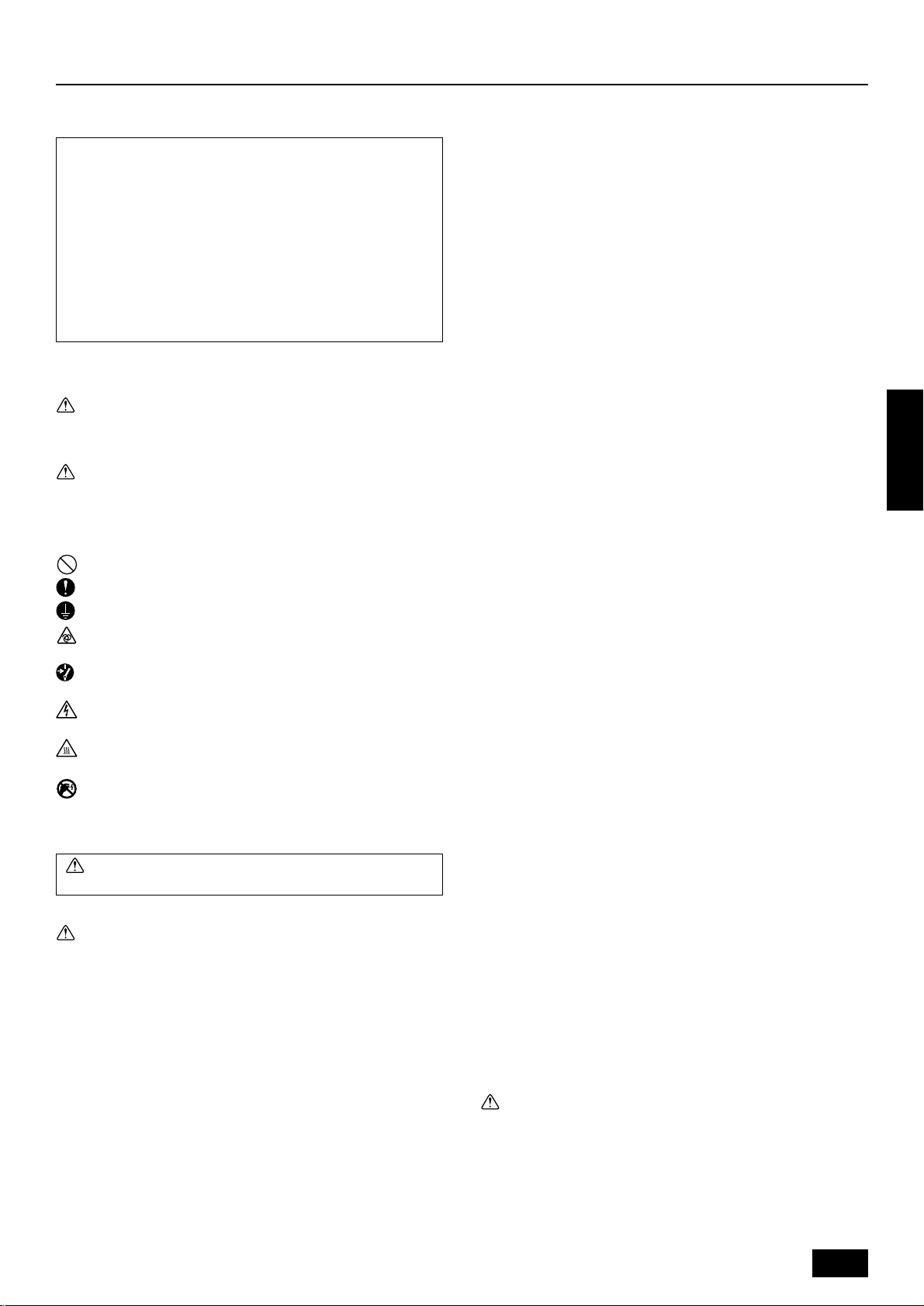
Symbols used in the illustrations
: Indicates an action that must be avoided.
: Indicates that important instructions must be followed.
: Indicates a part which must be grounded.
: Indicates that caution should be taken with rotating parts. (This
symbol is displayed on the main unit label.) <Color: Yellow>
: Indicates that the main switch must be turned off before servicing.
(This symbol is displayed on the main unit label.) <Color: Blue>
: Beware of electric shock (This symbol is displayed on the main
unit label.) <Color: Yellow>
: Beware of hot surface (This symbol is display ed on the main unit
label.) <Color: Yellow>
: Please pay attention to electric shock fully because this is
ELV
not Safety Extra Low-Voltage (SELV) circuit.
And at servicing, please shut down the power supply for both
of Indoor Unit and Outdoor Unit.
Warning:
Carefully read the labels affixed to the main unit.
Warning:
• Ask the dealer or an authorized technician to install the air conditioner.
- Improper installation by the user ma y result in water leakage, elec-
tric shock, or fire.
• Install the air unit at a place that can withstand its weight.
- Inadequate strength may cause the unit to fall down, resulting in
injuries.
• Use the specified cables for wiring. Make the connections securely so that the outside force of the cable is not applied to the
terminals.
- Inadequate connection and fastening may gener ate heat and cause
a fire.
• Prepare for typhoons and other strong winds and earthquakes
and install the unit at the specified place.
- Improper installation may cause the unit to topple and result in in-
jury.
• Always use an air cleaner, humidifier, electric heater, and other
accessories specified by Mitsubishi Electric.
- Ask an authorized technician to install the accessories. Improper
installation by the user may result in water leakage, electric shock,
or fire.
• Never repair the unit. If the air conditioner must be repaired,
consult the dealer.
- If the unit is repaired improperly, water leakage, electric shock, or
fire may result.
• Do not touch the heat exchanger fins.
- Improper handling may result in injury.
• If refrigerant gas leaks during installation work, ventilate the
room.
- If the refrigerant gas comes into contact with a flame, poisonous
gases will be released.
• Install the air conditioner according to this Installation Manual.
- If the unit is installed improperly, water leakage, electric shock, or
fire may result.
• Have all electric work done by a licensed electrician according
to “Electric Facility Engineering Standard” and “Interior Wire
Regulations”and the instructions given in this manual and always use a special circuit.
- If the power source capacity is inadequate or electric work is per-
formed improperly, electric shock and fire may result.
• Securely install the outdoor unit terminal cover (panel).
- If the terminal cover (panel) is not installed properly, dust or water
may enter the outdoor unit and fire or electric shock may result.
• When installing and moving the air conditioner to another site,
do not charge the it with a refrigerant different from the refrigerant (R407C) specified on the unit.
- If a different refrigerant or air is mixed with the original refrigerant,
the refrigerant cycle may malfunction and the unit may be damaged.
• If the air conditioner is installed in a small room, measures must
be taken to prevent the refrigerant concentration from exceeding the safety limit even if the refrigerant should leak.
- Consult the dealer regarding the appropriate measures to prevent
the safety limit from being exceeded. Should the refrigerant leak
and cause the safety limit to be exceeded, hazards due to lack of
oxygen in the room could result.
• When moving and reinstalling the air conditioner, consult the
dealer or an authorized technician.
- If the air conditioner is installed improperly, water leakage, electric
shock, or fire may result.
• After completing installation work, make sure that refrigerant
gas is not leaking.
- If the refrigerant gas leaks and is exposed to a fan heater, stove,
oven, or other heat source, it may generate noxious gases.
• Do not reconstruct or change the settings of the protection devices.
- If the pressure switch, thermal switch, or other protection de vice is
shorted and operated forcibly, or parts other than those specified
by Mitsubishi Electric are used, fire or explosion may result.
• To dispose of this product, consult your dealer.
• The installer and system specialist shall secure safety against
leakage according to local regulation or standards.
- Following standards may be applicable if local regulation are not
available.
• Pay a special attention to the place, such as a basement, etc.
where refrigeration gas can stay, since refrigeration is heavier
than the air.
1.2. Precautions for devices that use
R407C refrigerant
Caution:
• Do not use the existing refrigerant piping.
- The old refrigerant and refrigerator oil in the existing piping con-
tains a large amount of chlorine which may cause the refrigerator
oil of the new unit to deteriorate.
• Use refrigerant piping made of C1220 (CU-DHP) phosphorus
deoxidized copper as specified in the JIS H3300 “Copper and
copper alloy seamless pipes and tubes”. In addition, be sure
that the inner and outer surfaces of the pipes are clean and free
ENGLISH
3
Page 4

of hazardous sulphur, oxides, dust/dirt, shaving particles, oils,
moisture, or any other contaminant.
- Contaminants on the inside of the refrigerant piping may cause the
refrigerant residual oil to deteriorate.
• Store the piping to be used during installation indoors and keep
both ends of the piping sealed until just before brazing. (Store
elbows and other joints in a plastic bag.)
- If dust, dirt, or water enters the refrigerant cycle, deterioration of
the oil and compressor trouble may result.
• Use ester oil, ether oil or alkylbenzene (small amount) as the
refrigerator oil to coat flares and flange connections.
- The refrigerator oil will degrade if it is mixed with a large amount of
mineral oil.
• Use liquid refrigerant to fill the system.
- If gas refrigerant is used to seal the system, the composition of the
refrigerant in the cylinder will change and performance may drop.
• Do not use a refrigerant other than R407C.
- If another refrigerant (R22, etc.) is used, the chlorine in the refriger-
ant may cause the refrigerator oil to deteriorate.
• Use a vacuum pump with a reverse flow check valve.
- The vacuum pump oil may flow back into the refrigerant cycle and
cause the refrigerator oil to deteriorate.
• Do not use the following tools that are used with conventional
refrigerants.
(Gauge manifold, charge hose, gas leak detector, reverse flow
check valve, refrigerant charge base, vacuum gauge, refrigerant recovery equipment)
- If the conventional refrigerant and refrigerator oil are mixed in the
ENGLISH
R407C, the refrigerant may deteriorated.
- If water is mixed in the R407C, the refrigerator oil may deteriorate.
- Since R407C does not contain any chlorine, gas leak detectors for
conventional refrigerants will not react to it.
• Do not use a charging cylinder.
- Using a charging cylinder may cause the refrigerant to deteriorate.
• Be especially careful when managing the tools.
- If dust, dirt, or water gets in the refrigerant cycle, the refrigerant
may deteriorate.
1.3. Before getting installed
• Install the power cable so that tension is not applied to the cable.
- Tension may cause the cable to break and generate heat and cause
a fire.
• Install an leak circuit breaker, as required.
- If an leak circuit breaker is not installed, electric shock may result.
• Use power line cables of sufficient current carrying capacity
and rating.
- Cables that are too small may leak, generate heat, and cause a
fire.
• Use only a circuit breaker and fuse of the specified capacity.
- A fuse or circuit breaker of a larger capacity or a steel or copper
wire may result in a general unit failure or fire.
• Do not wash the air conditioner units.
- Washing them may cause an electric shock.
• Be careful that the installation base is not damaged by long use.
- If the damage is left uncorrected, the unit may fall and cause per-
sonal injury or property damage.
• Install the drain piping according to this Installation Manual to
ensure proper drainage. Wrap thermal insulation around the
pipes to prevent condensation.
- Improper drain piping may cause water leakage and damage to
furniture and other possessions.
• Be very careful about product transportation.
- Only one person should not carry the product if it weighs more than
20 kg.
- Some products use PP bands for packaging. Do not use any PP
bands for a means of transportation. It is dangerous.
- Do not touch the heat exchanger fins. Doing so may cut your fin-
gers.
- When transporting the outdoor unit, suspend it at the specified po-
sitions on the unit base. Also support the outdoor unit at four points
so that it cannot slip sideways.
• Safely dispose of the packing materials.
- Packing materials, such as nails and other metal or wooden parts,
may cause stabs or other injuries.
- Tear apart and throw away plastic pac kaging bags so that children
will not play with them. If children pla y with a plastic bag which was
not torn apart, they face the risk of suffocation.
Caution:
• Do not install the unit where combustible gas may leak.
- If the gas leaks and accumulates around the unit, an explosion
may result.
• Do not use the air conditioner where food, pets, plants, precision instruments, or artwork are kept.
- The quality of the food, etc. may deteriorate.
• Do not use the air conditioner in special environments.
- Oil, steam, sulfuric smoke, etc. can significantly reduce the per-
formance of the air conditioner or damage its parts.
• When installing the unit in a hospital, communication station,
or similar place, provide sufficient protection against noise.
- The inverter equipment, private power generator, high-frequency
medical equipment, or radio communication equipment may cause
the air conditioner to operate erroneously , or f ail to operate. On the
other hand, the air conditioner may affect such equipment by creating noise that disturbs medical treatment or image broadcasting.
• Do not install the unit on a structure that may cause leakage.
- When the room humidity exceeds 80% or when the drain pipe is
clogged, condensation may drip from the indoor unit. Perform collective drainage work together with the outdoor unit, as required.
1.4. Before getting installed (moved) -
electrical work
Caution:
• Ground the unit.
- Do not connect the ground wire to gas or water pipes, lightning
rods, or telephone ground lines. Improper grounding may result in
electric shock.
• The reverse phase of L lines (L1, L2, L3) can be detected (Error
cord : 4103), but the reverse phase of L lines and N line can be
not be detected.
- The some electric parts should be damaged when power is sup-
plied under the miss wiring.
1.5. Before starting the test run
Caution:
• Turn on the power at least 12 hours before starting operation.
- Starting operation immediately after turning on the main power
switch can result in severe damage to internal parts. Keep the pow er
switch turned on during the operational season.
• Do not touch the switches with wet fingers.
- Touching a switch with wet fingers can cause electric shock.
• Do not touch the refrigerant pipes during and immediately after
operation.
- During and immediately after operation, the refrigerant pipes are
may be hot and may be cold, depending on the condition of the
refrigerant flowing through the refrigerant piping, compressor, and
other refrigerant cycle parts. Your hands may suffer burns or frostbite if you touch the refrigerant pipes.
• Do not operate the air conditioner with the panels and guards
removed.
- Rotating, hot, or high-voltage parts can cause injuries.
• Do not turn off the power immediately after stopping operation.
- Alwa ys wait at least five minutes before turning off the power. Oth-
erwise, water leakage and trouble may occur.
4
Page 5
2. Combination with indoor units
The indoor units connectable to this unit are shown below.
Outdoor unit model
name
Note:
1. The total capacity of connected indoor unit models represents the total sum of the figures expressed in the indoor model name.
2. Combinations in which the total capacity of the connected indoor units exceeds the capacity of the outdoor unit will reduce the capacity
of each indoor unit below the rated capacity during simultaneous operation. Therefore, if circumstances allows, combine indoor units
within the capacity of the outdoor unit.
3. A transmission booster (RP) is required when the number of connected indoor unit models in a cooling system exceeds the number of
models specified in the chart below.
* The maximum number of units that can be controlled is determined by the indoor unit model, the type of remote controller and their
capabilities.
(*1)
Capability of the
connected indoor units
*1 If even one unit that is higher than 200 exists in the cooling system, the maximum capacity will be “200 or higher”.
Total capacity of
connected indoor unit
models
300 to 780PUHY-P600
325 to 845PUHY-P650
350 to 910PUHY-P700
375 to 975PUHY-P750
Number of connected indoor units that can be
connected without a RP.
200 or lower
200 or higher
Quantity of connectable
indoor unit
PMFY-P25 · 32 · 40 · 63 VBM
PLFY- P32 · 40 · 50 · 63 · 80 · 100 · 125 VKM
PLFY- P20 · 25 · 32 · 40 · 50 · 63 · 80 · 100 · 125 VLMD
PEFY-P20· 25 · 32 VML
PEFY-P40· 50 · 63 · 71 · 80 · 100 · 125 · 140 · 200 · 250 VMH
3 to 32
Remote controller type
The number of indoor units and the total number of remote controllers is displayed within the parenthesis ( ).
PCFY-P40 · 63 · 100 · 125 VGM
PKFY-P20 · 25 VAM
PKFY-P32· 40 · 50 VGM
PFFY- P20 · 25 · 32 · 40 · 50 · 63 VLEM
PFFY- P20 · 25 · 32 · 40 · 50 · 63 VLRM
PDFY-P20 · 25 · 32 · 40 · 50 · 63 · 71 · 80 · 100 · 125 VM
Model name of connectable indoor unit
Remote controller PAR-F 25MA
Prior to Ver. E After Ver. F
16 (32) 20 (40)
16 (32) 16 (32)
ENGLISH
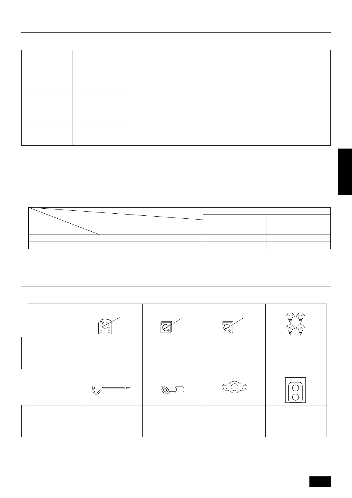
3. Confirmation of parts attached
This outdoor unit is attached with the parts below. Please check the quantity for each item.
Name 1 Conduit mounting plate 2 Conduit mounting plate 3 Conduit mounting plate 4 Tapping screw M4 × 12
Shape
PUHN-P200YMF-B
PUHN-P250YMF-B
Model name
Name 5 Oil balance pipe 6 Connecting pipe 7 Packing 8 Seal
Shape
PUHN-P200YMF-B
PUHN-P250YMF-B
Model name
ø40
1114
1112
ø33
ø27
insideø23 outsideø35
insideø23 outsideø35
*6 Connecting pipe is fixed with the unit.
5
Page 6
4. Outdoor unit configuration
The unit (PUHY-P600/650/700/750YSMF-B) consists of a combination of variable capacity units (PUHY-P400/500YMF-B) and constant capacity units
(PUHN-P200/250YMF-B). A CMC-30A (optional) is required when using a combination of these units.
Super Y Variable capacity unit Constant capacity unit
PUHY-P600YSMF-B
PUHY-P650YSMF-B
PUHY-P700YSMF-B
PUHY-P750YSMF-B
CMC-30A (optional)
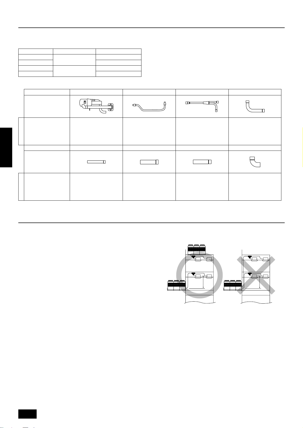
Name 1 Distributer (gas) 2 Oil balance pipe 2 3 Distributer (liquid) 4 Connecting pipe
Shape
CMC-30A 1 1 1 1
Model name
Name 5 Connecting pipe 6 Connecting pipe 7 Connecting pipe 8 Elbow
PUHY-P400YMF-B
PUHY-P500YMF-B
PUHN-P200YMF-B
PUHN-P250YMF-B
PUHN-P200YMF-B
PUHN-P250YMF-B
ENGLISH
Model name
Shape
CMC-30A 1 1 1 2
5. Selection of installation site
Select space for installing outdoor unit, which will meet the following
conditions:
• no direct thermal radiation from other heat sources
• no possibility of annoying neighbors by noise from unit
• no exposition to strong wind
• with strength which bears weight of unit
• note that drain flows out of unit when heating
• with space for air passage and service work shown below
Because of the possibility of fire, do not install unit to the space where
generation, inflow, stagnation, and leak of combustible gas is expected.
• Avoid unit installation in a place where acidic solution and spra y (sulfur)
are often used.
• When having cooling operation at an outside air temperature of below 10°C, in order to obtain steady operation of unit, select an installation site not exposed directly to rain and snow, or install air outlet
and inlet ducts. (Refer to Page 11.) Install the outdoor unit at the
same position on the same floor, or above, the indoor unit. (See the
figure at the right.)
• Do not use unit in any special environment where oil, steam and
sulfuric gas exist.
Installation restriction on outdoor unit when cooling operation is performed
when the outdoor air temperature is 10°C or lower.
A
(Same floor as indoor unit, or floor above)
A 4 m or less
6
Page 7
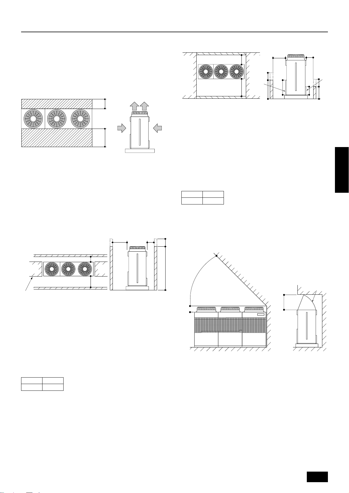
6. Space required around unit
C
B
A
B
650
325
A
C
H
h
Hh
E
D
6.1. Individual installation
Basic space required
A space of at least 250 mm is necessary at the back for inlet air. Taking
servicing, etc. from the rear into account, a space of about 450 mm
should be provided, the same as at the front.
D
A
B
C
<Top view> <Side view>
A 250 mm or more
B 450 mm or more
C Front (outside of machine room)
D Top discharge (open in principle)
E Front inlet (open in principle)
F Rear inlet (open in principle)
When inlet air enters from right and left sides of unit
When unit is surrounded by walls
<Side view>
A L
1 or more
B L
FE
2 or more
C Front
D Front panel
E Rear panel
Note:
• Wall heights (H) of the front and the back sides shall be within
height of front panel and rear panel.
• If the panel height is exceeded, add the “h” dimension of the
figure above to L
L
1 L2
1 and L2 in the table above.
ENGLISH
450 250
Example: When h is 100
The L1 dimension becomes 450+100 = 550 mm.
A
B
B
C
C
A
D
<Side view>
A L1 or more
B L
2 or more
C Front
D No restrictions on wall height (left and right)
Note:
• Wall heights (H) of the front and the back sides shall be within
overall height of unit.
• When the total height is exceeded, add the “h” dimension of the
figure above to L1 and L2 in the table above.
L1 L2
450 250
When there is an obstruction above the unit
Hh
A
E
D
B
CF
When there is little space
up to an obstruction
A 45° or more
B 300 mm or more
C Front
D 1000 mm or more
E Air outlet guide (procured at the site)
F Rear
7
Page 8
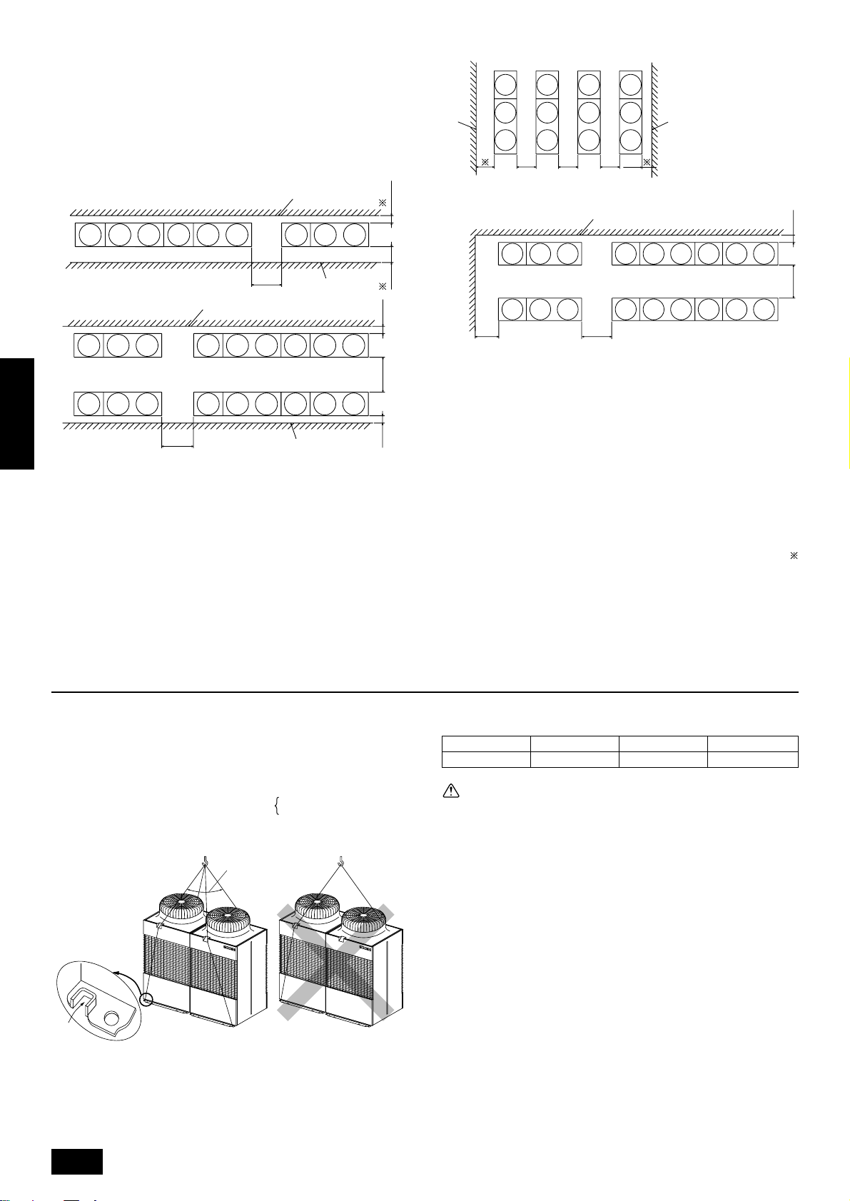
6.2. Collective installation and continu-
D D
B
B
B
A
A
A
CCCC
FEFFF
G
C
C
E
ous installation
Space required for collective installation and continuous installation:
When installing several units, leave the space between each block as
shown below considering passage for air and people.
B
A
A
ENGLISH
D
B
D
A
CC
B
FE
EE
CC
B
G
A
A (Must be open)
B Wall height (H)
C Front
D 1000 mm or more
E 250 mm or more
F 450 mm or more
G 900 mm or more
Note:
• Open in the two directions
• In case wall height (H) exceeds overall height of unit, add “h”
dimension (h=wall height <H> – overall height of unit) to
marked dimension.
• If there is a wall at both the front and the rear of the unit, install
up to three units consecutively in the side direction and provide
a space of 1000 mm or more as inlet space/passage space for
each three units.
7. Lifting method and weight of product
• When carrying the unit suspended, pass the ropes under the unit
and use the two suspension points each at the front and rear.
• Always lift the unit with ropes attached at four points so that impact is
not applied to the unit.
• Attach the ropes to the unit at an angle of 40° or less.
• Use two ropes at least A m long.
B
A 40° or less
B Rope suspension part
A
7 ··· PUHN-P200/250YMF-B
A =
8 ··· PUHY-P400/500YMF-B
Dangerous!
Weight of product:
PUHY-P400 PUHY-P500 PUHN-P200 PUHN-P250
455 kg 475 kg 240 kg 255 kg
Caution:
Be very careful to carry product.
- Do not have only one person to carry product if it is more than 20 kg.
- PP bands are used to pack some products. Do not use them as a
mean for transportation because they are dangerous.
- Do not touch heat exchanger fins with y our bare hands. Otherwise you
may get a cut in your hands.
- Tear plastic packaging bag and scrap it so that children cannot play
with it. Otherwise plastic pac kaging bag may suffocate children to death.
- When carrying in outdoor unit, be sure to support it at four points. Carrying in and lifting with 3-point support may make outdoor unit unstable, resulting in a fall of it.
8
Page 9
8. Installation of unit
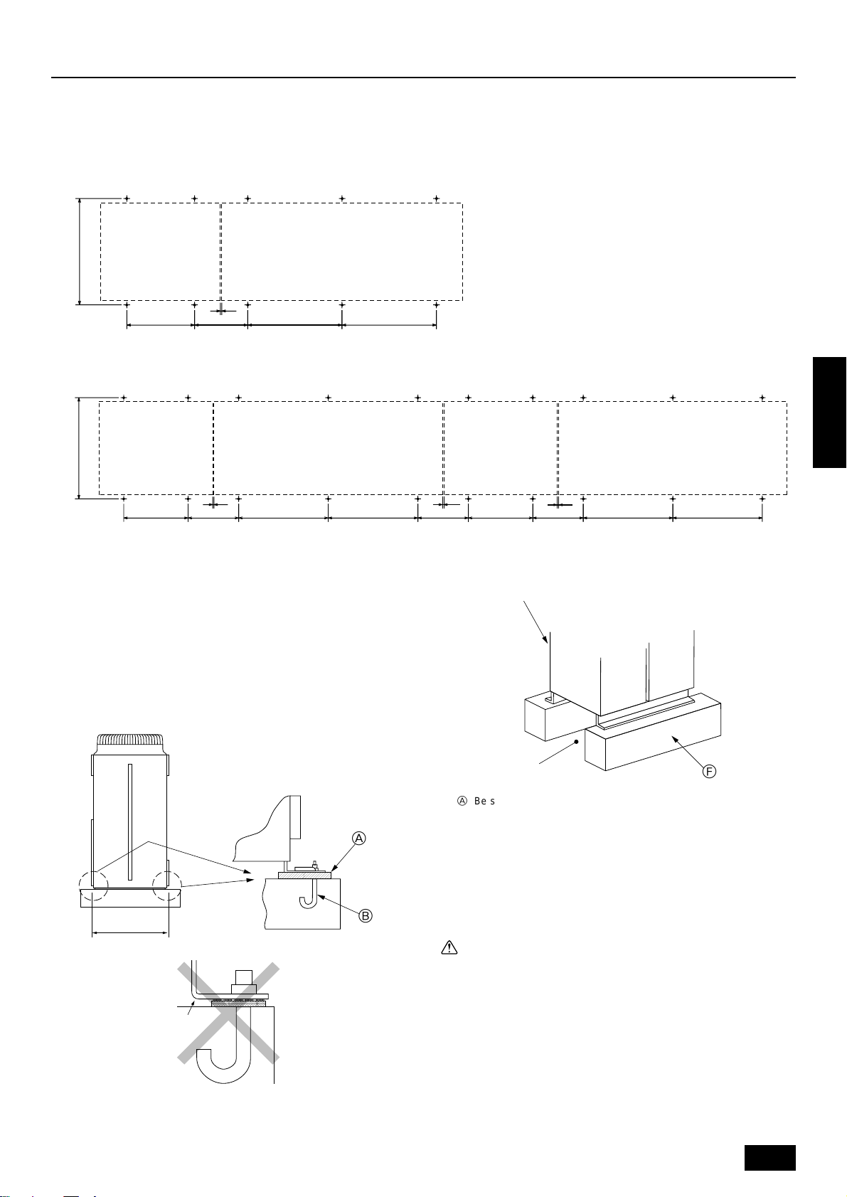
8.1. Location of anchor bolt
Mount the constant capacity unit on the left and variable capacity unit on the right of the same frame (as seen from the front of the unit). Allow
10 mm of clearance between the units.
• Individual installation (Unit: mm)
Constant capacity unit
Constant capacity unit Variable capacity unit
880±5
10
Service side
Service side
• Example of collective installation
Constant capacity unit
Constant capacity unit Variable capacity unit
880±5
10
Variable capacity unit
780±2780±2440560±2
Variable capacity unit
780±2780±2440560±2
8.2. Installation
• Fix unit tightly with bolts as shown below so that unit will not fall down
due to earthquake or gust.
• Use concrete or angle for foundation of unit.
• Vibration may be transmitted to the installation section and noise
and vibration may be generated from the floor and walls, depending
on the installation conditions. Therefore, provide ample
vibrationproofing (cushion pads, cushion frame, etc.).
Constant capacity unit
Constant capacity unit Variable capacity unit
440 780±2780±2440560±2
Service side
Service side
For collective installation, provide a 10 mm gap between units.
1010
Variable capacity unit
D
ENGLISH
880±5
C
A
B
E
A Be sure that the cor ners are firmly seated. If the corners are not firmly
seated, the installation feet may be bent.
B M10 anchor bolt procured at the site.
C Corner is not seated.
D Unit
(Provide ample vibrationproofing between the unit and the foundation by
using cushion pads, cushion frame, etc.)
E Piping and wiring space (bottom piping, bottom wiring)
F Concrete foundation
F
Warning:
• Be sure to install unit in a place strong enough to withstand its
weight.
Any lack of strength may cause unit to fall down, resulting in a
personal injury.
• Have installation work in order to protect against a str ong wind
and earthquake.
Any installation deficiency may cause unit to fall down, resulting in a personal injury.
When building the foundation, give full attention to the floor strength,
drain water disposal <during operation, drain water flows out of the unit>,
and piping and wiring routes.
9
Page 10
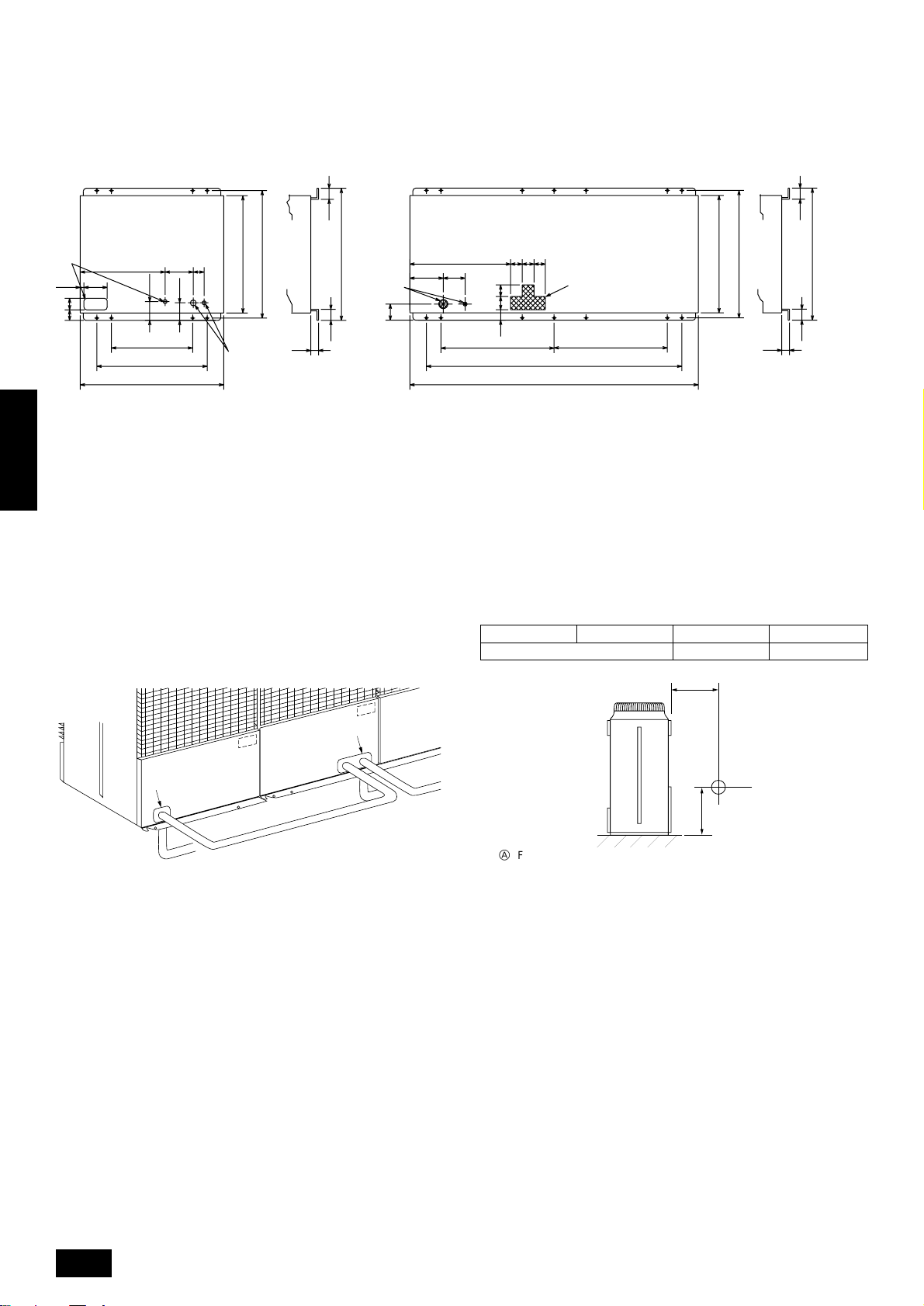
Down piping and down wiring precautions
When down piping and down wiring are performed, be sure that foundation and base work does not block the base through holes. When down
piping is performed, make the foundation at least 150 mm high so that
the piping can pass under the bottom of the unit.
<PUHN-P200/250YMF-B>
55
A
25
8073
ENGLISH
584
160
A Bottom piping through hole
B (bolt hole)
C (bolt hole for old models)
D (unit width)
E (unit depth)
F Bottom wiring through hole
G (bolt hole for packing)
560
760
990
130
B
G
D
194
121
B
75
840E880
F
910
55
15
8.3. Connecting direction for refrigerant
piping
Two connecting directions are available f or refriger ant piping of the outdoor unit, bottom piping and front piping, as shown below:
<PUHY-P400/500YMF-B>
694
150230
F
111
8.4. Noise level
56
788280
B
840E880
910
A
73 90 80
780
B
1760
1990
G
D
780
B
PUHY-P400 PUHY-P500 PUHN-P200 PUHN-P250
60/61 dB (A-weighted)
56 dB (A-weighted) 57 dB (A-weighted)
56
15
(50/60Hz)
A
A
B
A Knock-out hole
B Bottom piping
C Front piping
D Connect piping (to constant capacity unit)
B
D
C
Note:
In the case of bottom piping, build a 100 mm or higher foundation
so that piping will go through the bottom of the unit.
1m
A
1m
B
A Front
B Measuring point
Measuring location: a room free from echoes and reverberations
10
Page 11
9. Caution for snow and seasonal wind
In cold and/or snowy areas, sufficient countermeasures to wind and snow
damages should be taken for operating unit in normal and good condition in winter time. Ev en in the other areas, full consider ation is required
for installation of unit in order to prevent abnormal operations caused by
seasonal wind or snow. When rain and snow directly fall on unit in
the case of air-conditioning operations in 10 or less degrees centigrade outdoor air, mount inlet and outlet ducts on unit for assuring
stable operations.
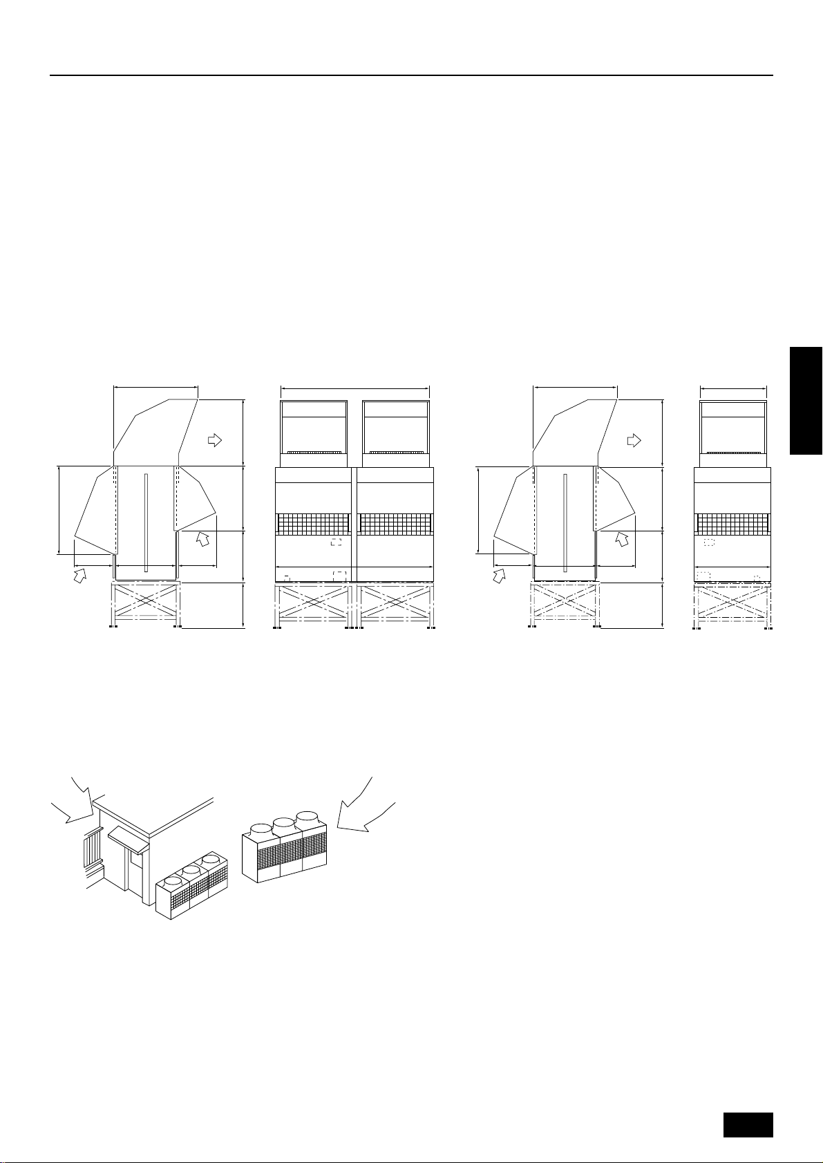
9.1. Snow and seasonal wind
■ Prevention of wind and snow damages in cold or snowy areas:
Refer to the figure of snow hood shown below:
• Snow hood
<PUHY-P400/500YMF-B>
1093
A
1888
Note:
1. Height of frame base for snow damage prevention (H) shall be
twice as high as expected snowfall. Width of frame base shall
not exceed that of the unit. The frame base shall be made of
angle steel, etc., and designed so that sno w and wind slip through
the structure. (If frame base is too wide, snow will be accumulated on it.)
2. Install unit so that seasonal wind will not directly lash against
openings of inlet and outlet ducts.
3. Build frame base at customer referring to this figure.
Material : Galvanized steel plate 1.2T
Painting : Overall painting with polyester powder
Color : Munsell 5Y8/1 (same as that of unit)
4. When the unit is used in a cold region and the heating operation
is continuously performed for a long time when the outside air
temperature is below freezing, install a heater to the unit base
or take other appropriate measures to prevent water from freezing on the base.
<PUHN-P200/250YMF-B>
1093
888
A
ENGLISH
1145
B
A Outlet
B Inlet
B
500(840)500
(670) 821 903
H
(1990)
1145
B
B
500(840)500
(670) 821 903
H
9.2. Countermeasure to seasonal wind
Referring to the figure shown below, take appropriate measures which
will suit the actual situation of the place for installation.
AA
(990)
A Seasonal wind
11
Page 12
10. Refrigerant piping installation
Connecting the piping is a terminal-branch type in which refrigerant piping from the outdoor unit is branched at the terminal and connected to each of
the indoor units.
The method of connection consists of flare connections at the indoor units, flange connections for the piping of the outdoor unit and flare connections
for the liquid, oil balance piping. Note that the branched sections are brazed.
Warning:
Always use extreme care to prevent the refrigerant gas (R407C) from leaking while using fire or flame. If the refrigerant gas comes in contact
with the flame from any source, such as a gas sto ve, it breaks do wn and generates a poisonous gas which can cause gas poisoning. Ne ver
weld in an unventilated room. Al wa ys conduct an inspection f or gas leakage after installation of the refrigerant piping has been completed.
10.1. Areas of caution
1 Use the following materials for refrigeration piping.
• Material: Seamless phosphorous deoxidized copper pipe, C1220T-OL or C1220T-O (Note: C1220T-OL is preferred).
• Size: Refer to pages 14 to 15.
2 Commercially available piping often contains dust and other materials. Always blow it clean with a dry inert gas.
3 Use care to prevent dust, water or other contaminants from entering the piping during installation.
4 Reduce the number of bending portions as much as possible, and make bending radius as big as possible.
5 Always use the branch piping set shown below , which are sold separ ately. This unit requires a CMC-30A (optional).
Branch pipe set name
Line branching Header branching
Total of units down-
ENGLISH
stream less than 160
CMY-Y102S-F CMY-Y102L-F CMY-Y202-F CMY-Y302-F CMY-Y104-E CMY-Y107-E CMY-Y1010-E
Total of units down-
stream 161 to 330
Total of units downstream
more than 331 to 630
Total of units down-
stream more than 631
4 branching 7 branching 10 branching
6 If the diameters of the branch piping of the designated refrigerant piping differs, use a pipe cutter to cut the connecting section and then use an
adapter for connecting different diameters to connect the piping.
7 Always observe the restrictions on the refrigerant piping (such as rated length, the difference between high/low pressures, and piping diameter).
Failure to do so can result in equipment failure or a decline in heating/cooling performance.
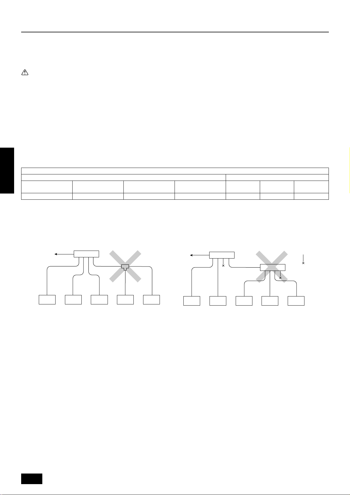
8 A second branch cannot be made after a header branch. (These are shown by ×.)
A
A
B
A To outdoor unit
B Capped piping
9 Always use good-quality materials for brazing.
0 The City Multi Series Super Y will stop due an abnormality due to excessive or insufficient coolant. At such a time, alw a ys properly charge the unit.
When servicing, always check the notes concerning pipe length and amount of additional refrigerant at both locations, the refrigerant volume
calculation table on the back of the service panel and the additional refrigerant section on the labels for the combined number of indoor units (Refer
to pages 14 to 15).
A Use liquid refrigerant to fill the system.
B Never use refrigerant to perform an air purge. Always evacuate using a vacuum pump.
C Always insulate the piping properly. Insufficient insulation will result in a decline in heating/cooling perf ormance, water drops from condensation and
other such problems (Refer to pages 25 to
D When connecting the refrigerant piping, make sure the ball valve of the outdoor unit is completely closed (the factory setting) and do not operate it
until the refrigerant piping for the outdoor and indoor units has been connected, a refrigerant leakage test has been performed and the evacuation
process has been completed.
E Always use a non-oxidizing brazing material for brazing the parts. If a non-oxidizing br azing material is not used, it could cause clogging or damage
to the compressor unit. (Details of the piping connections and valve operation can be found on pages 16 to 20.)
F Never perform outdoor unit piping connection work when it is raining.
26
).
12
Page 13

Warning:
When installing and moving the air conditioner to another site, do not charge the it with a refrigerant different from the refrigerant (R407C)
specified on the unit.
- If a different refrigerant or air is mixed with the original refrigerant, the refrigerant cycle may malfunction and the unit may be damaged.
Caution:
• Use refrigerant piping made of C1220T-OL phosphorus deoxidized copper. In addition, be sure that the inner and outer surfaces of the
pipes are clean and free of hazardous sulphur, oxides, dust/dirt, shaving particles, oils, moisture, or any other contaminant.
- Contaminants on the inside of the refrigerant piping may cause the refrigerant residual oil to deteriorate.
• Use liquid refrigerant for sealing.
- Sealing with gas refrigerant will change the composition of the refrigerant in the cylinder and reduce the unit’s performance.
• Never use existing refrigerant piping.
- The large amount of chlorine in conventional refrigerant and refrigerator oil in the existing piping will cause the new refrigerant to deteriorate.
• Store the piping to be used during installation indoors and keep both ends of the piping sealed until just before brazing.
- If dust, dirt, or water gets into the refrigerant cycle, the oil will deteriorate and the compressor may fail.
• Do not use a charging cylinder.
- Using a charging cylinder may cause the refrigerant to deteriorate.
ENGLISH
13
Page 14
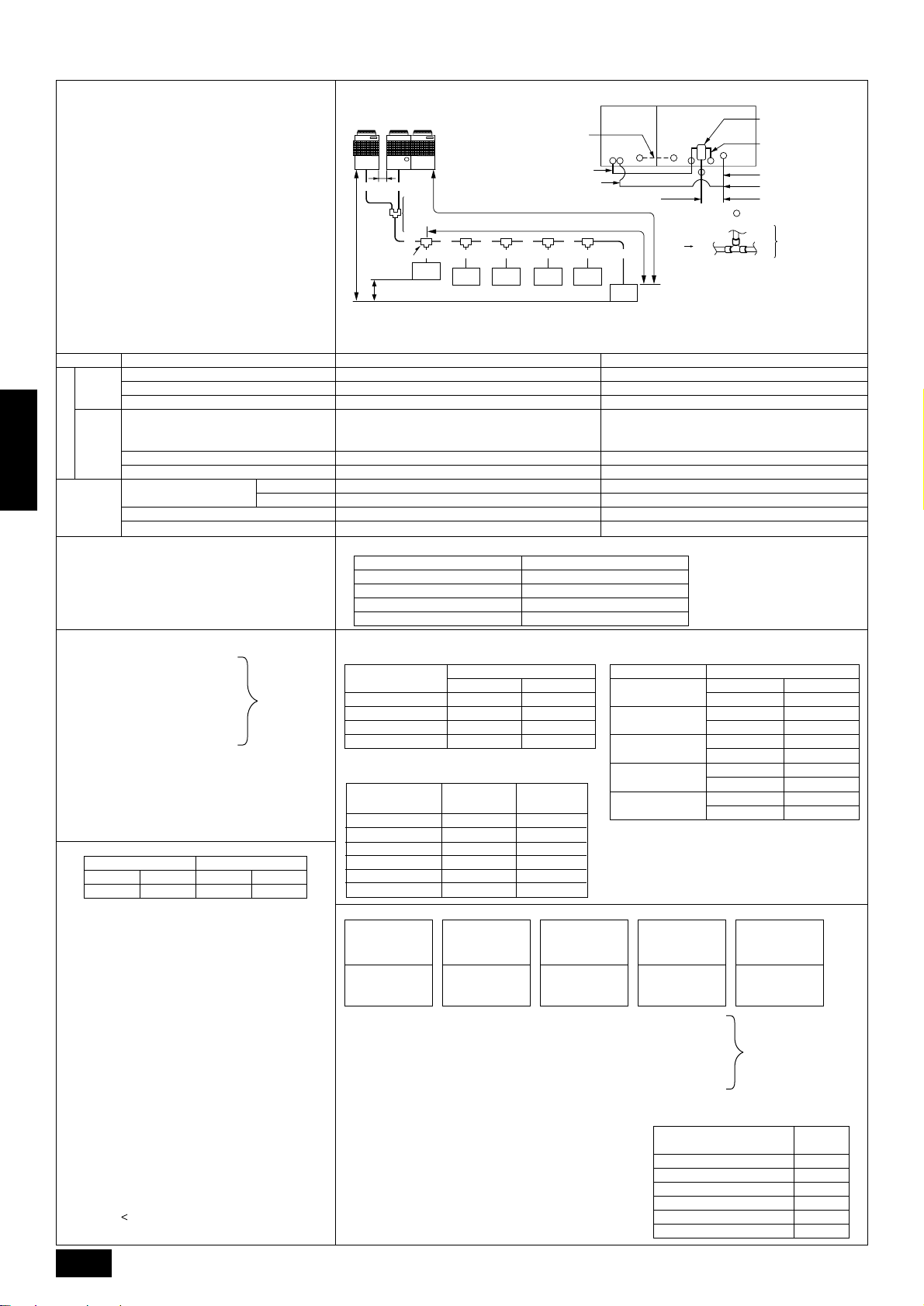
10.2. Refrigerant piping system
A
To down stream units
Liquid line (main) CGas line (main) C
Liquid line B
Gas line B
Gas line A
Distributer (gas) (optional)
Distributer (liguid) (optional)
Liquid line A
Oil balance pipe (optional) I
(for distribution within the unit)
Constant
capacity unit
Variable
capacity unit
:indicates piping connection points
Line-branch method
Connection examples
(connecting to six indoor units)
Indoor
side
Outdoor
side
Permissible length
ENGLISH
Permissible high/
Low difference
■ Selecting the refrigerant branch kit
Use the table to the right to make the selection based
on the model total of indoor units downstream from the
branch section.
■ Select each section of refrigerant piping
(1) Section from outdoor unit to first
branch (C)
(2) Sections from branch to indoor
unit (a, b, c, d, e, f)
(3) Section from branch to branch
(D, E, F, G)
Select the size from the table to the right.
Variable capacity unit Constant capacity unit
■
Additional refrigerant charge
The outdoor unit is charged with refrigerant at the time of shipping according to the chart above. As this charge does not
include the amount needed for extended piping, additional charging for each refrigerant line will be required on site. In order that
future servicing may be properly provided, always keep a record
of the size and length of each refrigerant line and the amount of
additional charge by writing it in the space provided on the outdoor unit.
■
Calculation of additional refrigerant charge
•
Calculate the amount of additional charge based on the length
of the piping extension and the size of the refrigerant line.
•
Use the table to the right as guide to calculating the amount
of additional charging and charge the system according.
•
If the calculation results in a fraction of less than 0.1 kg, round
up to the next 0.1 kg. For example, if the result of the calculation was 23.28 kg, round the result up to 23.3 kg.
•
If the total amount of refrigerant including the amount of refrigerant sealed in the outdoor unit when shipped from the
factor plus additional refrigerant for extension piping e xceeds
73 kg, use 73 kg as the total amount of refrigerant.
Amount of refrigerant when shipped from factory + added
refrigerant
14
Total piping length
Item
Farthest piping length (L)
Farthest piping length after first branch (r)
Oil balance pipe
Distributer (liquid)/Variable capacity unit, Constant capacity unit
Distributer (gas)/Constant capacity unit
Indoor/Outdoor
Outdoor upper
Outdoor lower
Indoor/Indoor
Variable capacity unit/Constant capacity unit
Each section
of piping
(kg)
400 500 200 250
16 22 6.5 8.5
73 kg.
=
Constant
Constant
Constant
capacity unit
capacity unit
H
Note 1: Because it is built into the variable capacity unit, B is used to carry liquid only. Set the constant capacity unit and
Variable
Variable
capacity unit
capacity unit
A B
G
Note 1
Note 1
Distributer
Distributer
(liquid)
(liquid)
Distributer
Distributer
(gas)
(gas)
CG
First branch
First branch
h
acde
oor
Ind
Indoor
unit
unit
1
variable capacity unit in accordance with the G dimension given in the figure above (G = 0.01 m).
Oil balance pipe (optional) I
(for distribution within the unit)
Gas line A
Liquid line A
L
R
D
EF
b
Indoor
Indoor
unit
unit
3
Indoor
Indoor
unit
unit
Indoor
Indoor
unit
unit
245
capacity unit
Gas line (main) C
Indoor
Indoor
unit
unit
Indoor
Indoor
unit
unit
f
6
Variable
capacity unit
Distributer (gas) (optional)
Gas line B
Liquid line B
Distributer (liguid) (optional)
Liquid line (main) C
:indicates piping connection points
To down stream units
Note:
• The model total for downstream units shown
in the table below is the model total when
viewed from Point A in the drawing abo ve.
• With the exception of PUHY -P600YSMF-B,
the first branch is always CMY-Y302-F.
Piping components Tolerance
A+B+C+D+E+F+G+a+b+c+d+e+f 220 m or less
A (B)+C+D+E+F+G+f 100 m or less (Max. equivalent length 125 m)
D+E+F+G+f 40 m or less
The included oil balance pipe must be used. If any other piping is used, the length
I
of the oil balance pipe must be no more than 3 m (max. equivalent length 4 m),
and height from the bottom of the unit must be no more than 0.1 m.
A, B (Liquid line) 4 m or less (Max. equivalent length 5 m)
A (Gas line) 4 m or less (Max. equivalent length 5 m)
H 50 m or less
H 40 m or less
h 15 m or less
–
Must be installed on same frame, and there must be no high/low difference.
Select the branch kit, sold separately , from the tab le below . (Each kit contains a refrigerant and gas piping set.)
Downstream unit model total Branch kit model
160 or less CMY-Y102S-F
161 to 330 CMY-Y102L-F
331 to 630 CMY-Y202-F
631 or more CMY-Y302-F
(1) Refrigerant piping diameter in section from outdoor
unit to first branch (outdoor unit piping diameter)
Model
PUHY-P600YSMF-B
PUHY-P650YSMF-B
PUHY-P700YSMF-B
PUHY-P750YSMF-B
Piping diameter (mm)
Liquid line Gas line
ø19.05 ø38.1
ø19.05 ø44.45
ø19.05 ø44.45
ø19.05 ø44.45
(3) Refrigerant piping diameter in section from
branch to branch
Downstream unit
model total
80 or less
81 to 160
161 to 330
331 to 480
481 to 630
631 or more
Liquid line
(mm)
ø9.52
ø12.7
ø12.7
ø15.88
ø15.88
ø19.05
Gas line
(mm)
ø15.88
ø19.05
ø25.4
ø31.75
ø38.1
ø44.45
(2) Refrigerant piping diameter in section from branch
to indoor unit (indoor unit piping diameter)
Model number Piping diameter (mm)
20 · 25 · 32 · 40
50 · 63 · 71 · 80
100 · 125 · 140
200
250
Liquid line ø6.35
Gas line ø12.7
Liquid line ø9.52
Gas line ø15.88
Liquid line ø9.52
Gas line ø19.05
Liquid line ø12.7
Gas line ø25.4
Liquid line ø12.7
Gas line ø28.58
<Additional charge>
Liquid pipe size
total length of
ø19.05 × 0.29
(m) × 0.29 (kg/m)
<Example> Indoor 1 : 125 A : ø12.7 3 m a :ø9.52 15 m
Liquid pipe size
total length of
ø15.88 × 0.25
+++++ α
(m) × 0.25 (kg/m)
2 : 125 B : ø15.88 1 m b :ø9.52 15 m
Liquid pipe size
total length of
ø12.7 × 0.12
(m) × 0.12 (kg/m)
3 : 125 C : ø19.05 40 m c :ø9.52 10 m
4 : 125 D : ø15.88 10 m d :ø9.52 5 m
5 : 100 E : ø15.88 5 m e :ø9.52 5 m
Liquid pipe size
total length of
ø9.52 × 0.06
(m) × 0.06 (kg/m)
Liquid pipe size
total length of
ø6.35 × 0.024
(m) × 0.024 (kg/m)
At the conditions
below:
6:40 F:ø12.7 5 m f : ø6.35 5 m
The total length of each liquid line is as follows
ø19.05 : C = 40 m
ø15.88 : B + D + E = 1 + 10 + 5 = 16 m
ø12.7 : A + F + G = 3 + 5 + 5 = 13 m
ø9.52 : a + b + c + d + e = 50 m
ø6.35 : f = 5 m
Therefore,
<Calculation example>
Additional
refrigerant charge = 40 × 0.29 +16 × 0.25 + 13 × 0.12 +
50 × 0.06 + 5 × 0.024 + 3.0 = 23.3 kg
G:ø12.7 5 m
Value of α
Total capacity of
connecting indoor units
to Model 80 1.0 kg
Models 81 to 160 1.5 kg
Models 161 to 330 2.0 kg
Models 331 to 480 2.5 kg
Models 481 to 630 3.0 kg
Models 631 or more 4.0 kg
α
Page 15

Multiple line/header
Connection examples
(connecting to six indoor units)
Item
Total piping length
Indoor
Farthest piping length (L)
side
Farthest piping length after first branch (r)
Outdoor
Permissible length
Permissible high/
Low difference
Oil balance pipe
side
Distributer (liquid)/Variable capacity unit, Constant capacity unit
Distributer (gas)/Constant capacity unit
Indoor/Outdoor
Outdoor upper
Outdoor lower
Indoor/Indoor
Variable capacity unit/Constant capacity unit
■ Selecting the refrigerant branch kit
Use the table to the right to make the selection based
on the model total of indoor units downstream from the
branch section or on the number of indoor units to be
connected on the header branch.
■ Select each section of refrigerant piping
(1) Section from outdoor unit to first
branch (C)
(2) Sections from branch to indoor
unit (a, b, c, d, e, f)
Each section
of piping
(3) Section from branch to branch
(D, E, F)
Select the size from the table to the right.
(kg)
Variable capacity unit Constant capacity unit
400 500 200 250
16 22 6.5 8.5
■
Additional refrigerant charge
The outdoor unit is charged with refrigerant at the time of shipping according to the chart above. As this charge does not
include the amount needed for extended piping, additional charging for each refrigerant line will be required on site. In order that
future servicing may be properly provided, always keep a record
of the size and length of each refrigerant line and the amount of
additional charge by writing it in the space provided on the outdoor unit.
■
Calculation of additional refrigerant charge
•
Calculate the amount of additional charge based on the length
of the piping extension and the size of the refrigerant line.
•
Use the table to the right as guide to calculating the amount
of additional charging and charge the system according.
•
If the calculation results in a fraction of less than 0.1 kg, round
up to the next 0.1 kg. For example, if the result of the calculation was 20.03 kg, round the result up to 20.1 kg.
•
If the total amount of refrigerant including the amount of refrigerant sealed in the outdoor unit when shipped from the
factor plus additional refrigerant for e xtension piping exceeds
73 kg, use 73 kg as the total amount of refrigerant.
Amount of refrigerant when shipped from factory + added
refrigerant
73 kg.
=
Constant
Constant
capacity unit
capacity unit
Oil balance pipe (optional) I
Oil balance pipe (optional) I
(for distribution within the unit)
Constant
Constant
capacity unit
capacity unit
H
Note 1: Because it is built into the variable capacity unit, B is used to carry liquid only. Set the constant capacity unit and
Variable
Variable
capacity unit
capacity unit
Note 1
Note 1
BA
G
Distributer
Distributer
(liquid)
(liquid)
Distributer
Distributer
(gas)
(gas)
C F
First branch
First branch
(branch joint)
(branch joint)
D
Branch joint
Branch joint
variable capacity unit in accordance with the G dimension given in the figure above (G = 0.01 m).
Indoor
In door
(for distribution within the unit)
L
R
E
Indoor
Indoor
In door
In door
b
a
unit
unit
unit
unit
12
unit
unit
3
Gas line A
Liquid line A
c
Gas line A
Liquid line A
d
In door
Indoor
unit
unit
4
Gas line (main) C
Branch header
Branch header
e
In door
In door
Indoor
Indoor
unit
unit
5
Variable
Variable
capacity unit
capacity unit
:indicates piping connection points
:indicates piping connection points
A
Note:
• The model total for downstream units
shown in the table below is the model
Cap
f
Cap
total when viewed from Point A in the
drawing above.
With the exception of PUHY-P600YSMF-
•
unit
unit
h
6
B, the first branch is always CMY-Y302-F.
Distributer (gas) (optional)
Distributer (gas) (optional)
Gas line B
Gas line B
Liquid line B
Liquid line B
Distributer (liguid) (optional)
Distributer (liguid) (optional)
Liquid line (main) C
Liquid line (main) CGas line (main) C
To down stream units
To down stream units
Piping components Tolerance
A+B+C+D+E+F+a+b+c+d+e+f 220 m or less
A (B)+C+D+E+c 100 m or less (Max. equivalent length 125 m)
D+E+c 40 m or less
The included oil balance pipe must be used. If any other piping is used, the length
I
of the oil balance pipe must be no more than 3 m (max. equivalent length 4 m),
and height from the bottom of the unit must be no more than 0.1 m.
A, B (Liquid line) 4 m or less (Max. equivalent length 5 m)
A (Gas line) 4 m or less (Max. equivalent length 5 m)
H 50 m or less
H 40 m or less
h 15 m or less
–
Must be installed on same frame, and there must be no high/low difference.
Select the branch kit, sold separately , from the tab le below . (Each kit contains a refrigerant and gas piping set.)
Line branching Header branching
Total of units downstream
less than 160
Total of units downstream
161 to 330
Total of units downstream
331 to 630
Total of units downstream
more than 631
CMY-Y102S-C CMY-Y102L-C CMY-Y202-C CMY-Y302-C
(1) Refrigerant piping diameter in section from out-
door unit to first branch (outdoor unit piping diameter)
Model
PUHY-P600YSMF-B
PUHY-P650YSMF-B
PUHY-P700YSMF-B
PUHY-P750YSMF-B
Piping diameter (mm)
Liquid line Gas line
ø19.05 ø38.1
ø19.05 ø44.45
ø19.05 ø44.45
ø19.05 ø44.45
(2) Refrigerant piping diameter in section from
branch to indoor unit (indoor unit piping diameter)
Model number Piping diameter (mm)
20 · 25 · 32 · 40
50 · 63 · 71 · 80
100 · 125 · 140
(3) Refrigerant piping diameter in section from branch
to branch
Downstream unit model total
Liquid line (mm) Gas line (mm)
80 or less ø9.52 ø15.88
4 branching
header
7 branching
header
CMY-Y104 CMY-Y107 CMY-Y1010
Liquid line ø6.35
Gas line ø12.7
Liquid line ø9.52
Gas line ø15.88
Liquid line ø9.52
Gas line ø19.05
200
250
Liquid line ø12.7
Gas line ø25.4
Liquid line ø12.7
Gas line ø28.58
10 branching
header
81 to 160 ø12.7 ø19.05
161 to 330 ø12.7 ø25.4
331 to 480 ø15.88 ø31.75
481 to 630 ø15.88 ø38.1
631 or more ø19.05 ø44.45
<Additional charge>
Liquid pipe size
total length of
ø19.05 × 0.29
(m) × 0.29 (kg/m)
Liquid pipe size
total length of
ø15.88 × 0.25
+++++ α
(m) × 0.25 (kg/m)
Liquid pipe size
total length of
ø12.7 × 0.12
(m) × 0.12 (kg/m)
Liquid pipe size
total length of
ø9.52 × 0.06
(m) × 0.06 (kg/m)
Liquid pipe size
total length of
ø6.35 × 0.024
(m) × 0.024 (kg/m)
<Example> Indoor 1 : 125 A : ø12.7 3 m a :ø9.52 10 m
2 : 125 B : ø15.88 1 m b :ø9.52 5 m
3 : 125 C : ø19.05 30 m c :ø9.52 5 m
4 : 125 D : ø15.88 10 m d :ø9.52 10 m
At the conditions
below:
5 : 100 E : ø12.7 5 m e :ø9.52 15 m
6:40 F:ø12.7 15 m f :ø6.35 5 m
The total length of each liquid line is as follows
ø19.05 : C = 30 m
ø15.88 : B + D = 1 + 10 = 11 m
ø12.7 : A + E + F = 3 + 5 + 15 = 23 m
ø9.52 : a + b + c + d + e = 10 + 5 + 5 + 10 + 15 = 45 m
ø6.35 : f = 5 m
Therefore,
<Calculation example>
Additional
refrigerant charge = 30 × 0.29 +11 × 0.25 + 23 × 0.12 +
45 × 0.06 + 5 × 0.024 + 3.0 = 20.1 kg
Value of α
Total capacity of
connecting indoor units
to Model 80 1.0 kg
Models 81 to 160 1.5 kg
Models 161 to 330 2.0 kg
Models 331 to 480 2.5 kg
Models 481 or more 3.0 kg
α
ENGLISH
15
Page 16

10.3. Precautions concerning piping connection and valve operation
<For variable capacity unit>
• Connect piping and operate valves e xactly as described in the figure below.
• After performing the following distributor (gas) connection, remove the con-
necting pipe included with the gas ball valve of the variable capacity unit, and
mount the distributor (gas) (optional).
1 When brazing the distributor (gas), braze it outside of the unit before mount-
<When shipped from
the manufacturer>
3
A
^
<After installation>
O
ing on the variable capacity unit.
2 During the time when removing the connecting pipe with flange, remove
the seal attached on the back side of this sheet and paste it onto the flange
surface of the ball valve to prevent the entry of dust into the valve.
3 The refrigerant circuit is closed with a round, close-packed packing at the
shipment to prevent gas leak between flanges. As no operation can be
1
1
B
done under this state, be sure replace the packing with the hollow packing
attached at the piping connection.
4 At the mounting of the hollow packing, wipe off dust attached on the flange
sheet surface and the packing. Coat refrigerating machine oil onto both
1
surfaces of the packing.
• After evacuation and refrigerant charge, ensure that the handle is fully open. If operating with the valve closed, abnormal pressure will be imparted
to the high- or low-pressure side of the refrigerant circuit, or a shortage of oil in the compressor may occur due to lack of oil flow between units, giving
damage to the compressor, four-way valve, etc.
For evacuating, be sure to provide an oil balance pipe between the variable capacity and constant capacity units.
•
• Determine the amount of additional refrigerant charge by using the formula, and charge refrigerant additionally through the service por t after
completing piping connection work.
• After completing work,
ENGLISH
shut the service port and cap tightly so that gas leaking does not occur.
• Connect ball valve piping in the order of (oil balance) → (liquid side) → (gas side).
Ball valve
Ball valve
Ball valve
(liquid side)
(liquid side)
E
Ball valve
(gas side)
(gas side)
E
A
S
3
F
G
H
Ball valve
Ball valve
(oil balance side)
(oil balance side)
E
S
O
ø15.88
To distributor
To distributor
(liquid)
(liquid)
ø12.7
To constant capacity unit
To constant capacity unit
O
S
O
ø28.6
I
(Figure shows valve fully open.)
(Figure shows valve fully open.)
J
S
B
C
D
Warning:
Braze the distributor (gas) outside the unit, before mounting distributor (gas)* to ball valve of the variable capacity unit.
- If brazed while mounted, the ball valve is heated and could result in cracking or gas leaks. The wiring inside the unit could also be burned.
16
Page 17

<For constant capacity unit>
Replace the solid packing.
Hollow packing
S
O
1
3
• Connect piping and operate valves e xactly as described in the figure below.
• Gas side connecting piping is already assembled when the equipment is shipped. (See figure
Replace the solid packing.
on right.)
1 When brazing to connecting pipe with flange, remove the connecting pipe with flange from
the ball valve, and braze at the outside of the unit.
2 During the time when removing the connecting pipe with flange, remove the seal attached
on the back side of this sheet and paste it onto the flange surface of the ball valv e to prev ent
the entry of dust into the valve.
3 The refrigerant circuit is closed with a round, close-packed packing at the shipment to pre-
vent gas leak between flanges. As no operation can be done under this state, be sure re-
Hollow packing
place the packing with the hollow packing attached at the piping connection.
4 At the mounting of the hollow packing, wipe off dust attached on the flange sheet surface
and the packing. Coat refrigerating machine oil onto both surfaces of the packing.
• After evacuation and refrigerant charge, ensure that the handle is fully open. If operating with the valve closed, abnormal pressure will be imparted
to the high- or low-pressure side of the refrigerant circuit, or a shortage of oil in the compressor may occur due to lack of oil flow between units, giving
damage to the compressor, four-w ay valve, etc.
•
For evacuating, be sure to provide an oil balance pipe between the variable capacity and constant capacity units.
• Determine the amount of additional refrigerant charge by using the formula, and charge refrigerant additionally through the service por t after
completing piping connection work.
• After completing work, shut the service port and cap tightly so that gas leaking does not occur.
C
D’
Ball valve
Ball valve
(Gas side)
(gas side)
E
O
Ball valve
Ball valve
(Liquid side)
(liquid side)
E
Ball valve
Ball valve
(Oil balance side)
(oil balance side)
E
The unit is set vertically between
The unit is set vertically between
the compressor and control box.
the compressor and control box.
ENGLISH
A
Fastening plate
S
S
O
MP35K
O
Fastening plate
S
F
ø28.6
G
ø12.7
To distributor
T o distributor
(liquid)
(liquid)
B
H’
To variable capacity unit
To variable capacity unit
ø12.7
To distributor (gas) inside
To distributor (gas) inside
variable capacity unit
variable capacity unit
(Figure shows valve fully open.)
(Figure shows valve fully open.)
Warning:
Be sure to remove the connecting pipe from the ball valve, and braze it outside the unit.
- If brazed while mounted, the ball valve is heated and could result in cracking or gas leaks. The wiring inside the unit could also be burned.
17
Page 18

A Valve stem
[Fully closed at the factory , when connecting the piping, when evacuating,
and when charging additional refrigerant. Open fully after the operations
above are completed.]
B Stopper pin [Prevents the valve stem from turning 90° or more.]
C Packing (accessory)
D Distributer (gas) (option)
[Mount packing (accessory) securely to the valve flange so that gas does
not leak. (screw tightening torque is 43 N·m (430 kg·cm).) Apply a coat of
refrigerating machine oil to both surfaces of the packing.]
D’ Connecting pipe (accessory)
[Use packing and securely install this pipe to the valve flange so that gas
leakage will not occur. (tightening torque: 25 N·m (250 kg·cm)) Coat both
surfaces of the packing with refrigerator oil.]
E Open (operate slowly)
F Cap, copper packing
[Remove the cap and operate the valv e stem. Alwa ys reinstall the cap after
operation is completed. (valve stem cap tightening torque: 25 N·m (250
kg·cm) or more)]
G Service port
[Use this port to evacuate the refrigerant piping and add an additional charge
at the site.
Open and close the port using a double-ended wrench.
Always reinstall the cap after operation is completed. (service port cap
tightening torque: 14 N·m (140 kg·cm) or more)]
H Flare nut
[Tightening torque: 80 N·m (800 kg·cm) ··· liquid, 55 N·m (550 kg·cm) ··· oil
blance
ENGLISH
Loosen and tighten this nut using a double-ended wrench.
Coat the flare contact surface with refrigerator oil.]
H’ Flare nut
[Tightening torque: 55 N·m (550 kg·cm)
Use a double spanner to open and close. Apply a coat of refrigerating
machine oil to the flare bonding surface.]
I ø38.1 (PUHY-P600YSMF-B)
ø44.5 (PUHY-P650/700/750YSMF-B)
J Field piping
[Braze to the connecting pipe. (when brazing, use unoxidized brazing.)]
Appropriate tightening torque by torque wrench
Copper pipe external dia. (mm) Tightening torque (N·m) / (kg·cm)
ø6.35 14 to 18 / 140 to 180
ø9.52 35 to 42 / 350 to 420
ø12.7 50 to 57.5 / 500 to 575
ø15.88 75 to 80 / 750 to 800
ø19.05 100 to 140 / 1000 to 1400
Tightening angle standard
Pipe diameter (mm) Tightening angle (°)
ø6.35, ø9.52 60 to 90
ø12.7, ø15.88 30 to 60
ø19.05 20 to 35
Note:
If a torque wrench is not available, use the following method as a
standard.
When you tighten the flare nut with a wrench, you will reach a point
where the tightening torque will abrupt increase. Turn the flare nut
beyond this point by the angle shown in the table above.
Caution:
• Always remove the connecting pipe from the ball valve and braze
it outside the unit.
- Brazing the connecting pipe while it is installed will heat the ball
valve and cause trouble or gas leakage. The piping, etc. inside the
unit may also be burned.
• Use ester oil, ether oil or alkylbenzene (small amount) as the
refrigerator oil to coat flares and flange connections.
- The refrigerator oil will degrade if it is mixed with a large amount of
mineral oil.
18
Page 19

10.4. Oil balance pipe connection method
• Oil balance piping can be took out from the front, bottom or side of the unit (left side for the variable capacity unit, right side for the constant capacity
unit).
• Connect piping and operate valves exactly as described below (for details, see item 10.3.).
1 After connecting oil balance pipe, be sure to evacuate using the service port of the variable capacity unit side valve.
2 After evacuating, be sure to fully open each valve stem. If you operate with the valve closed, a shortage of oil in the compressor may occur due
to lack of oil flow between units, which could result in damage to the compressor.
3 After completing work, shut the cap of the service port and handle section tightly so that gas leaking does not occur.
Warning:
Failure to connect the oil balance pipe will result in the compressor being damaged.
• Provide 10 mm of clearance between the variable capacity and constant capacity units. Position the v ariable capacity unit so that its front is f acing
on the right side and the constant capacity unit so that its front is facing on the left. Connect the oil balance pipe f or the optional CMC-30A according
to the following procedure.
1 Open the knock-out holes of the left side panel for the variable capacity unit, and the right side panel for the constant capacity unit.
2 After installing the units, flare-connect the piping included with the unit (ø12.7).
3 Block the clearance between units with the 2 seals included with the constant capacity unit.
10 mm (clearance between units)
10 mm (clearance between units)
Right side panel
(Constant capacity unit)
(Constant capacity unit)
Right side panel
Left side panel
Left side panel
(Variable capacity unit)
(Variable capacity unit)
ENGLISH
Control box
Compressor
Compressor
Ball valve (oil balance)
Ball valve (oil balance)
ø12.7 (flare)
ø12.7 (flare)
Oil balance pipe 1 (optional)
Oil balance pipe 1 (optional)
Seal material (2 pieces, included)
Seal material (2 pieces, included)
Through holes for oil balance pipe
Through holes for oil balance pipe
and transmission cables
and transmission cables
• If the oil balance piping for the constant capacity unit from the front of the unit is took out, bend the piping as shown in the figure below . (When doing
so, be careful not to the piping doesn’t touch the compressor or other parts.)
Front panel
Front panel
Knock-out holes for
Knock-out holes for
taking out oil balance pipe
taking out oil balance pipe
from front surface
from front surface
Control box
Compressor
Compressor
Oil balance pipe
Oil balance pipe
(field supply)
(field supply)
Control boxControl box
Control box
Control box
Oil balance pipe 2
Oil balance pipe 2
(optional)
(optional)
Flare connection (2 places)
Flare connection (2 places)
Tightening torque is 55 N·m (550 kg·cm)
Tightening torque is 55 N·m (550 kg·cm).
Open and close using a double
Open and close using a double
spanner. Apply a coat of refrigerating
spanner. Apply a coat of refrigerating
machine oil on both sides of the flare
machine oil on both sides of the flare
contact surface.
contact surface.
Ball valve (oil balance)
Ball valve (oil balance)
ø12.7 (flare)
ø12.7 (flare)
Ball valve (oil balance)
Ball valve (oil balance)
ø12.7 (flare)
ø12.7 (flare)
(Constant capacity unit)
(Constant capacity unit)
Oil balance pipe (Bend piping at the site.)
Oil balance pipe (Bend piping at the site.)
19
Page 20

10.5. Distributor (gas) connection
method
■ Taking out piping from the front direction
(1) Remove the copper cap and rubber packing attached to the pip-
ing and flange of the distributor (gas) (optional).
(2) Assemble outside the unit with the elbow (8) in the specified
shape and braze (see Fig. 1).
For the 600 type, braze the connecting pipe (7) also.
Brazing
Brazing
8Elbow
8
Elbow
7
Connecting pipe
8
Elbow
8Elbow
(3) Braze the connecting pipe (4) and piping assembled in step (2)
to the distributor (gas) so that the connecting pipe is attached as
shown in Fig. 2. For assembly procedure, see Fig. 3. When brazing piping, cool the brazed portion of the distributor side piping
with a dampened waste cloth to prevent heating by brazing.
Flange
Flange
ENGLISH
7Connecting pipe
Fig. 1
■ Taking out piping in the downward direction
(1) Remove the copper cap and rubber packing attached to the pip-
ing and flange of the distributor (gas) (optional).
(2) Assemble outside the unit with the elbow (8), connecting pipe
(7 for 600 type), or connecting pipe (6 for types other than 600)
in the specified shape and braze (see Fig. 4).
Brazing
Brazing
Brazing
Brazing
(3) Braze the connecting pipe (5) and connecting piping assembled
in step (2) to the distributor (gas) outside the unit. For assembly
procedure, see Fig. 5. When brazing piping, cool the braz ed portion of the distributor side piping with a dampened waste cloth to
prevent heating by brazing.
8Elbow
8Elbow
For 600
For 600
For other than 600
For other than 600
Fig. 4
7Connecting pipe
:
: 7Connecting pipe
:
: 6Connecting pipe
6Connecting pipe
4Connecting
Connecting
4
pipe
pipe
Elbow assembly
Elbow assembly
4Connecting pipe
4
Connecting pipe
Flange
Flange
Fig. 2
Distributor (gas)
Distributor (gas)
Fastening plate
Fastening plate
Fastening plate
Fastening plate
Distributor (gas)
Distributor (gas)
5Connecting pile
5
Connecting pile
Flange
Flange
Fastening plate
Fastening plate
Distributor (gas)
Distributor (gas)
Fig. 5
The rest of the procedure is the same as for “Running piping from front
direction.”
Caution:
When brazing, cool with a waste cloth dampened with water so that
the flange and ends of the distributor side piping don’t get heated.
- Part could be damaged if not cooled sufficiently.
Fig. 3
(4) Connect the ø12.7 oil balance pipe to the ball valve of the vari-
able capacity unit (oil balance) and constant capacity unit.
(5) Connect the ø15.88 piping branched by the distributor (liquid) to
the ball valve of the variable capacity unit (liquid side).
(6) Insert the distributor (gas) into the variable capacity unit and con-
nect to the flange of the ball valve (gas side). (Use a socket wrench
and socket wrench extension.) When doing so, be sure to mount
the included packing between the ball valve (gas side) and flange
of the distributor.
(7) Fasten the plate of the distributor (gas) to the frame of the unit
with screws.
(8) Connect and braze the ø44.45 (ø38.1 for 600 type) gas piping
(main pipe) and ø28.58 gas pipe that connects the constant capacity unit with the distributor (gas).
20
Page 21

10.6. How to install branch pipe
For detail, please observe the instruction manual attached to the optional refrigerant branch kit.
■ Joint
C
D
A
A To outdoor unit
B To branch piping or indoor unit
• Apart from the CMY -Y202-F and CMY-Y302-F gas side, there are no
restrictions on the posture for attaching joints.
• Ensure that the branch pipes for the CMY-Y202-F and CMY -Y302-F
gas side are attached horizontally or facing upwards (see the diagram below).
Horizontal Facing upwards
(Facing downwards is not possible)
Within ± 15°
• There is no limitation on the joint mounting configuration.
• If the diameter of the refrigerant piping selected by the procedures
described on pages 14 to 15 is different from the size of the joint,
match the sizes using a deformed joint. The deformed joint is included with the kit.
B
Within ± 15°
Within ± 15°
C Pipe cutter
D or
E Deformed joint
• When the number of pipes to be connected is smaller than the number
of header branches, install a cap to the unconnected branches. The
cap is included with the kit.
■ Distributer (liquid)
Field piping
Field piping
Variable
Variable
capacity unit
capacity unit
• Mount the distributor (liquid, optional CMC-30A) so that it is within
±15° in relation to the horizontal plane (see figure above).
Constant
Constant
capacity unit
capacity unit
E
±15°
ENGLISH
■ Header
A
B
A To outdoor unit
B To indoor unit
• No restriction is applied to the mounting posture of the header.
• If the diameter of the refrigerant piping selected using the proce-
dures described on pages 15 and the size of the joint is different,
match the sizes using a deformed joint. The deformed joint is included with the kit.
21
Page 22

10.7. Airtight test and evacuation, refrigerant charging
1 Airtight test
Perform with the stop valv e of the outdoor unit closed, and pressurize the connection piping and the indoor unit from the service port provided on the
stop valve of the outdoor unit. (Always pressurize from both the liquid pipe and the gas pipe service ports.)
A Nitrogen gas
B To indoor unit
C System analyzer
D Lo Knob
E Hi Knob
F Ball valve
G Liquid pipe
H Gas pipe
I Outdoor unit
J Service port
The method of conducting the airtight test is basically the same as for older models. Howe ver, since the restrictions have a large affect on deterioration
of the refrigerator oil, always observe them. Also, with nonazeotropic refrigerant (R407C, etc.), gas leakage causes the composition to change and
affects performance. Therefore, since the entire amount must be replaced if gas leakage occurs, perform the airtightness test cautiously.
A
C
D
B
LO HI
C
E
F
G
H
I
J
Airtight test procedure
1.Nitrogen gas pressurization
(1) After pressurizing to the design pressure (2.98 MPa) using nitrogen gas, let stand
ENGLISH
for about one day. If the pressure does not drop, airtightness is good.
However, if the pressure drops, since the leaking point is unknown, the following
bubble test may also be performed.
(2) After the pressurization described above, spray the flare connection parts, brazed
parts, flanges, and other parts that may leak with a bubbling agent (Kyuboflex,
etc.) and visually check for bubbles.
(3) After the airtight test, wipe off the bubbling agent.
2.Pressurization using refrigerant gas and nitrogen gas
(1) After sealing with liquid R407C from a cylinder and pressurizing to a gas pressure
of approximately 0.2 MPa, pressurize to the design pressure (2.98 MPa) using
nitrogen gas.
However , do not pressurize at one time. Stop during pressurization and check that
the pressure does not drop.
(2) Check for gas leaks by checking the flare connection parts, brazed parts, flanges,
and other parts which may leak using an R407C compatible electric leak detector.
(3) This test may be used together the with bubble type gas leak test.
• If a flammable gas or air (oxygen) is used as the pressurization gas, it may catch fire or explode.
• Do not use a refrigerant other than that indicated on the
unit.
• Sealing with gas from a cylinder will cause the composition of the refrigerant in the cylinder to change.
• Use a pressure gauge, charge box, and other parts especially for R407C.
• An electric leak detector for R22 cannot detect leaks.
• Do not use a haloid torch. (Leaks cannot be detected.)
Restriction
Caution:
Do not use a refrigerant other than R407C.
- If a refrigerant (R22, etc,) other than R407C is used, the chlorine in the refrigerant will cause the refrigerator oil to deteriorate.
22
Page 23

2 Evacuation
As shown in the figure below, evacuate with the stop valve of the outdoor unit closed and evacuate both the connection piping and the indoor unit
from the service port provided on the stop valve of the outdoor unit using a vacuum pump. (Alwa ys e v acuate from the service port of both the liquid
pipe and the gas pipe.) After the vacuum reaches 650 Pa, continue evacuation for at least one hour or more. Then, stop the vacuum pump and let
stand for one day and check if they vacuum does not rise. (If the v acuum rises, since water may be mixed in, pressurize up to 0.05 MPa using dry
nitrogen gas and evacuate again.)
Also evacuate the oil balance pipe that connects the variab le capacity and constant capacity units with the oil balance ball valves of both units shut.
Evacuate from the service port of the variable capacity unit ball valve with a vacuum pump.
Finally, seal with liquid refrigerant from the liquid pipe. Moreover, during operation, adjust the refrigerant amount from the gas pipe so that the
refrigerant is always an appropriate amount.
* Never perform air purging using refrigerant.
LO
A
B
A System analyzer
B Lo Knob
C Hi Knob
D Ball valve
E Liquid pipe
F Gas pipe
G Service port
H Three-way joint
I Valve
J Valve
K R407C cylinder
D
E
N
D
P
F
HI
C
H
G
J
I
G
M
O
K
ENGLISH
L
L Scale
Use a graviometer. (One that can measure down to 0.1 kg.)
M Vacuum pump
Use a vacuum pump with a reverse flow check valve.
(Recommended vacuum gauge: ROBINAIR 14830A Thermistor Vacuum
Gauge)
Also use a vacuum gauge that reaches 65 Pa or greater after oper ating for
five minutes.
N Constant capacity unit side
O Oil balance pipe
P Variable capacity unit side
23
Page 24

3 Refrigerant Charging
Since the refrigerant used with the unit is nonazerotropic, it must be charged in the liquid state. Consequently , when charging the unit with refrigerant
from a cylinder, if the cylinder does not hav e a syphon pipe, charge the liquid refrigerant by turning the cylinder upside-down as shown below. If the
cylinder has a syphon valve like that shown in the figure at the right, the liquid refrigerant can be charged with the cylinder standing upright.
Therefore, give careful attention to the cylinder specifications. If the unit should be charged with gas refrigerant, replace all the refrigerant with new
refrigerant. Do not use the refrigerant remaining in the cylinder.
B
A
C
A
[When cylinder does not have a syphon pipe] [When cylinder has a syphon pipe
A R407C cylinder
B Syphon pipe
C Liquid refrigerant
Note:
ENGLISH
Always add an appropriate amount of refrigerant. (For the refrigerant additional charge, see pages 14 to 15.) Also always seal the system
with liquid refrigerant. Too much or too little refrigerant will cause trouble.
Use a gauge manifold, charging hose, and other parts for the refrigerant indicated on the unit.
Note that it is not possible to determine if a correct amount is being used with the accumulator level (AL).
(Refrigerant can be charged with the
cylinder standing upright.)]
Warning:
When installing or moving the unit, do not charge it with refrigerant other than the refrigerant (R407C) specified on the unit.
- Mixing of different refrigerant, air, etc. may cause the refrigerant cycle to malfunction and result in severe damage.
Caution:
• Use a vacuum pump with a reverse flow check valve.
- If the vacuum pump does not hav e a re v erse flo w chec k valv e , the v acuum pump oil ma y flow bac k into the refrigerant cycle and cause deterioration of the refrigerator oil and other trouble.
• Do not use a charging cylinder.
- Using a charging cylinder may cause the refrigerant to deteriorate.
• Do not use the tools shown below used with conventional refrigerant.
(gauge manifold, charge hose, gas leak detector, check valve, refrigerant charge base, vacuum gauge, refrigerant recovery equipment)
- Mixing of conventional refrigerant and refrigerator oil may cause the refrigerator oil to deteriorate.
- Mixing of water will cause the refrigerator oil to deteriorate.
- R407C refrigerant does not contain any chlorine. Therefore, gas leak detectors for conventional refrigerants will not react to it.
• Manage the tools more carefully than normal.
- If dust, dirt, or water gets in the refrigerant cycle, the refrigerator oil will deteriorate.
24
Page 25

10.8. Thermal insulation of refrigerant
piping
Be sure to give insulation work to refrigerant piping by covering liquid
pipe and gas pipe separately with enough thickness heat-resistant
polyethylene, so that no gap is observed in the joint between indoor unit
and insulating material, and insulating materials themselves. When insulation work is insufficient, there is a possibility of condensation drip,
etc. Pay special attention to insulation work to ceiling plenum.
B
A
C
Heat
insulation
material A
Outer
covering B
Note:
When using polyethylene cover as covering material, asphalt roofing shall not be required.
Glass fiber + Steel wire
Adhesive + Heat - resistant polyethylene foam +
Adhesive tape
Indoor Vinyl tape
Floor exposed
Outdoor
Water-proof hemp cloth + Bronze asphalt
Water-proof hemp cloth + Zinc plate + Oily paint
D
A Steel wire
B Piping
C Asphaltic oily mastic or asphalt
D Heat insulation material A
E Outer covering B
• Do not insulate gas or low pressure pipe and liquid or high
pressure pipe together.
Bad example
A
E
B
C
D
E
A
Good example
E
E
B
D
Note:
No heat insulation must be provided for electric wires.
A Liquid pipe
B Gas pipe
C Electric wire
D Finishing tape
E Insulating material
A Liquid pipe
B Gas pipe
D Finishing tape
E Insulating material
ENGLISH
• Be sure to fully insulate connecting portion.
A
A These parts are not insulated.
25
Page 26

Penetrations
E
I
B
A Sleeve
B Heat insulating material
C Lagging
D Caulking material
E Band
F Waterproofing layer
G Sleeve with edge
ENGLISH
H Lagging material
Inner wall (concealed) Outer wall Outer wall (exposed)
D
A B
C
Floor (fireproofing) Roof pipe shaft Penetrating portion on fire limit and boundary wall
D
F
G
A B
D
I
J
B
H
G
B
F
I Mortar or other incombustible caulking
J Incombustible heat insulation material
When filling a gap with mortar, cover the penetration part with steel plate
so that the insulation material will not be caved in. For this part, use
incombustible materials for both insulation and cov ering. (Vinyl co vering
should not be used.)
A
1m1m
Branch piping section
Insulate the header using the insulation material attached to the branch
pipe kit as shown in the figure.
26
Page 27

11. Electrical work
11.1. Caution
1 Follow ordinance of your governmental organization for technical standard related to electrical equipment, wiring regulations and guidance of each
electric power company.
Warning:
Be sure to have authorized electric engineers do electric work using special circuits in accordance with regulations and this installation
manual. If power supply circuit has a lack of capacity or electric work deficiency, if may cause an electric shock or fire.
2 Install the outdoor unit transmission line away from the power source wiring so that it is not affected by electric noise from the power source . (Do not
run it through the same conduit.)
3 Be sure to provide designated grounding work to outdoor unit.
Caution:
Be sure to put outdoor unit to earth. Do not connect earth line to any gas pipe, water pipe, lightning rod or telephone earth line. If earth is
incomplete, it may cause an electric shock.
4 Give some allowance to wiring for electrical part box of indoor and outdoor units, because the box is sometimes removed at the time of service work.
5 Never connect the main power source to terminal block of transmission line. If connected, electrical parts will be burnt out.
6 Use 2-core shield cable for transmission line. ( mark in the figure below) If transmission lines of different systems are wired with the same
multiplecore cable, the resultant poor transmitting and receiving will cause erroneous operations. (× mark in the figure below)
7 Only the transmission line specified should be connected to the terminal block for outdoor unit transmission.
(Transmission line to be connected with indoor unit : Terminal block TB3 for transmission line, Other : Terminal block TB7 for centralized control)
Erroneous connection does not allow the system to operate.
8 In case to connect with the upper class controller or to conduct group operation in different refrigerant systems, the control line for transmission is
required between the outdoor units each other.
Connect this control line between the terminal blocks for centralized control. (2-wire line with no polarity)
When conducting group operation in different refrigerant systems without connecting to the upper class controller, replace the insertion of the short
circuit connector from CN41 of one outdoor unit to CN40.
9 Group is set by operating the remote controller.
0 Caution! If the electrical wiring connections (L1, L2, L3, N ) are made incorrectly, damage to the unit could result.
ENGLISH
A
C
TB3
TB7
B
D
TB3
TB7
TB3: Transmission line terminal board, TB7: Central control line terminal board
A Outdoor unit
B 2-core cable
C Indoor unit
D Remote controller
E Multi-core cable
B
TB3
TB3
TB7
TB7
A
C
E
D
27
Page 28

To prevent external tensile force from applying to the wiring connection
section of power source terminal block, use buffer bushing like PG
connection or the like.
knockout hole
T
e
n
s
i
l
e
f
o
r
c
e
A
D
A
F
G
E
B
C
B
11.2. Control box and connecting position of wiring
a. Variable capacity unit
1. Remove the total of six screws at the top and bottom, and remove
the service panel by pulling it forward (see the figure below).
A
A Service panel
ENGLISH
2. Remove the two screws on the left and right-hand of the base of the
control box and pull the overall cover downwards to detach it (a diagram with the control box cover removed is shown below).
3. Connect indoor and outdoor units through the terminal block for transmission lines (TB3). Outdoor units and connections to central control
systems go through the terminal block for centralized control (TB7).
When making an indoor/outdoor connection with shielded wiring, connect the shield ground to the shield screw. When making a central
control system connection with shielded wiring, use the terminal block
for centralized control (TB7).
When the CN41 power supply connector of an outdoor unit has been
replaced with a CN40, the shield terminal (S) for centralized control
(TB7) should also be connected to the shield screw.
4. How to use the conduit mounting plate
(1) Conduit mounting plates (ø46, ø53, ø62) are being provided.
Select conduit mounting plate based on the outside diameter of conduit to be used and mount it as shown in the figure.
(2) Fix power source wiring to control box by using buffer bushing for
tensile force (PG connection or the like).
J
B
F
LD1
CD A
E
L1 L2 L3
N
TB1
GHI
A INV board
B MAIN board
C Ten position
D One position
E Address switch
F FANCON board
G Power source
H Shield screw
I Transmission line
J RELAY board
K Shield terminal “S”
M1 M2M1 M2 S
TB7TB3
K
Tensile force
knockout hole
A ø46 mounting hole
B ø53 mounting hole
C ø62 knockout hole
D For the connection of conduit at bottom
E ø62 mounting hole
F For the connection of conduit at front
G The front of outdoor unit
To prevent external tensile force from applying to the wiring connection
section of power source terminal block, use buffer bushing like PG
connection or the like.
b. Constant capacity unit
1. The service panel is removed by removing the six screws at the top
and bottom and pulling it forward (see figure below).
Service panel
Service panel
28
Page 29

2. The control box cover is removed by removing the 2 screws and
pulling downward. (The control box with the cover removed is shown
in the figure below.)
3. Method of using conduit mounting plate
The equipment includes conduit mounting plates (ø27, ø33, ø40).
Select the mounting plate according to the diameter of the conduit
used, and mount as shown in the figure below.
ø
2
ø27 mounting plate
7
m
o
u
n
t
i
n
ø
ø33 mounting plate
If conduit is connected
If conduit is connected
from the front
from the front
g
3
3
m
o
u
n
t
i
n
g
ø
ø40
4
0
K
Knock-out hole
n
o
c
k
-
o
u
t
p
l
a
t
e
p
l
a
t
e
h
o
l
e
Tapping screw
Tapping screw
If conduit is connected
If conduit is connected from
the bottom
from the bottom
ø
ø40
4
0
m
mounting plate
o
u
n
ø
ø33 mounting plate
3
3
m
ø27 mounting plate
ø
2
o
u
7
n
t
i
u
n
t
i
n
g
p
Unit front
Unit front
n
g
l
a
t
e
m
o
t
i
n
g
p
l
a
t
e
p
l
a
t
e
4. Wiring connection
Connect indoor unit crossover cables of the transmission cables terminal block (TB3) of the variable capacity unit to the transmission
cables terminal block (TB3). When making an indoor/outdoor connection with shielded wiring, connect the shield ground to the shield
terminal (TB3).
10 1
Address
Address
CONT. board
CONT. board
L1 L2 L3 N
M1 M2 S
Controlbox
Controlbox Power
Power
terminal block
terminal block
(TB1)
(TB1)
Transmission
Transmission
cables terminal block
cables terminal block
(TB3)
(TB3)
ENGLISH
c. Transmission booster (optional)
(For details, see item 11.3. “Wiring transmission cables”)
Connect 220/230/240 VAC to L/N of power terminal block (TB1).
Connect the ground to the terminal of power terminal block (TB1).
Connect the outdoor unit side transmission cables to A/B of transmission cables terminal block 1 (TB2).
Connect the outdoor unit side shield to S of transmission cables terminal block 1 (TB2).
Connect additional indoor unit side transmission cables to A/B of transmission cables terminal block 2 (TB3).
Connect additional indoor unit side shield to S of transmission cables terminal block 2 (TB3).
Power terminal
Power terminal
block (TB1)
block (TB1)
and Earth
and Earth
TRANSMISSION BOOSTER
MODEL
PAC-SF46EPA
POWER RATING
WEIGHT
MADE IN JAPAN
220-240V:0.7A ~/N
50
3.4kg
UP
Transmission cables
Transmission cables
terminal block 2 (TB3)
terminal block 2 (TB3)
Transmission cables
Transmission cables
terminal block 1 (TB2)
terminal block 1 (TB2)
29
Page 30

11.3. Wiring transmission cables
Wiring method, address setting method and permissible wiring length differ according to and whether or not you are using transmission booster. Check
permissible wiring length before wiring.
A may be required depending on the number of indoor units.
Item 4 “Wiring examples” gives typical wiring examples (a to c).
a. System using remote controller (1 outdoor unit)
b. System using remote controller (system operated as a group among multiple refrigerant systems)
c. System using power supply extension unit for transmission booster (combination of systems a to b)
1 Connecting a transmission booster
A transmission booster (RP) is required when the number of connected indoor unit models in a cooling system exceeds the number of models specified
in the chart below.
* The maximum number of units that can be controlled is determined by the indoor unit model, the type of remote controller and their capabilities.
Remote controller type
(*1)
Capability of the
connected indoor units
*1 If even one unit that is higher than 200 exists in the cooling system, the maximum capacity will be “200 or higher”.
2 Name, code and possible unit connections
ENGLISH
Outdoor unit
Indoor unit
Remote controller
Other
*1 A transmission booster (RP) may be required depending on the number of connected indoor unit controllers.
Name Code Possible unit connections
Variable capacity unit controller
Constant capacity unit controller
Indoor unit controller
Remote controller (*1)
Transmission booster unit
Number of connected indoor units that can be
connected without a RP.
200 or lower
200 or higher
The number of indoor units and the total number of remote controllers is displayed within the parenthesis ( ).
OC
1 unit per 1 OC
OS
2 to 32 units per 1 OC (*1)
IC
2 units maximum per group
RC
0 to 1 unit per 1 OC (*1)
RP
–
Remote controller PAR-F 25MA
Prior to Ver. E After Ver. F
16 (32) 20 (40)
16 (32) 16 (32)
3 Types of control cables
(1) Wiring transmission cables
• Types of transmission cables
Shielding wire CVVS or CPEVS
• Cable diameter
More than 1.25 mm
• Maximum wiring length within 200 m
(2) Remote control cables
Kind of remote control cable 2-core cable (unshielded)
Cable diameter 0.5 to 0.75 mm
Remarks
4 Wiring examples
Typical wiring examples are shown on pages 32 to 36 (Wiring examples A to C).
2
2
When 10 m is exceeded, use cable with the same
specifications as (1) Transmission line wiring.
30
Page 31

ENGLISH
31
Page 32

A. Example of the use of the shielded cable in a single coolant system (Setting of addresses is necessary)
Example of control line wiring Wiring method, address setting
a.
1) Standard
L
1
OS
(52)
TB3
M1 M2 S
Shielded cable
Shielded cable
OC
(51)
TB3 TB7
M1M2
M1M2 S
3
L
1
r
• One remote control unit for each indoor unit.
Within ( ): Address
TB5
M1M2 S
TB6
(101)
RC
IC
(01)
TB13
123
L
2
IC
(02)
TB5
TB13
M1M2 S
123
2
r
TB6
(102)
RC
Run the wire to terminals M1 and M2 the variable capacity unit (OC)
transmission line terminal block (TB3) and to terminals M1 and M2 on
the constant capacity unit (OS) transmission line terminal block (TB3)
as well as to the terminals M1 and M2 of the transmission line terminal
block (TB5) of each indoor unit (IC). (Two-wire, no polarity)
Also, run the shielded ground wire to the ground terminal of the
variable capacity unit, the S terminal of the constant capacity unit (TB3),
and the S terminal of each indoor unit (TB5).
b.
Connect the wires to terminals M1 and M2 of the transmission line
terminal block (TB5) in each indoor unit (IC) and connect them to the
remote control (RC) terminal block (TB6).
c.
Set the address setting switch as shown in the following table.
Unit
Indoor unit
Remote control
Variable capacity
unit
Constant capacity
unit
Note 1.
If the address of the variable capacity unit or the constant capacity unit is set at 100, set one of the address switches at 01 ~ 50.
Note 2.
It is not necessary to set the 100’s position in the remote control
unit.
Range
01 to 50
101 to 150
Note 2
51 to 100
Note 1
51 to 100
Note 1
Setting method
—
Indoor unit address + 100
The smallest address of
the indoor units + 50
Variable capacity unit ad-
dress + 1
2) 2 Remote control operation
ENGLISH
(52)
TB3
M1 M2 S
Shielded cable
Shielded cable
• 2 remote control units for 1 indoor
unit.
OCOS
(51)
TB3 TB7
M1M2
M1M2 S
TB6
(101)
RC
(Main remote
(Main remote
controller)
controller)
3) Group operation
OS
(52)
TB3
M1 M2 S
Shielded cable
Shielded cable
OC
(51)
TB3 TB7
M1M2
M1M2 S
• Operation of multiple indoor units with 1 remote controller.
TB5
M1M2 S
TB5
M1M2 S
TB6
(101)
RC
IC
(01)
TB13
123
TB6
(151)
RC
(Sub remote
(Sub remote
controller)
controller)
(01)
TB13
123
M1M2 S
TB6
(102)
RC
(Main remote
(Main remote
controller)
controller)
M1M2 S
TB5
TB5
IC
(02)
TB13
123
TB6
(152)
RC
(Sub remote
(Sub remote
controller)
controller)
(02)
TB13
123
a. Same as above
b. Same as above
c. Set the address setting switch as shown in the fol-
lowing table.
Unit
Indoor unit
Main remote
controller
Sub remote
controller
Variable capacity
unit
Constant capacity
unit
Range
01 to 50
101 to 150
Note 2
151 to 200
Note 2
51 to 100
Note 1
51 to 100
Note 1
Setting method
—
Indoor unit address + 100
Indoor unit address + 150
The smallest address of the
indoor units + 50
Variable capacity unit ad-
dress + 1
Notes 1, 2. Same as above
a. Same as above
b. Connect terminals A and B (M1 and M2) of the trans-
mission line terminal block (TB5) of the indoor unit
(IC Main) with the lowest address of all the indoor
units (IC) in the same group and the terminals on
the remote control (RC) terminal block (TB6).
c. Set the address setting switch as shown in the fol-
lowing table.
d. Within the same group, let the indoor unit (IC) which
functions the most be the IC (Main) unit.
Unit
Range
Setting method
Address of the indoor unit
IC (Main)
01 to 50
with the smallest address of
all the indoor units in the
same group.
Address of any of the indoor
units except the address of
IC (Sub)
01 to 50
the IC (Main). Let the
number be in sequence with
that of the IC (Main).
Main remote
controller
Sub remote
controller
Variable capacity
unit
Constant capacity
unit
101 to 150
151 to 200
51 to 100
51 to 100
Address of the IC (Main) in
Note 2
the same group + 100
Address of the IC (Main) in
Note 2
the same group + 150
The smallest address of the
Note 1
indoor units + 50
Variable capacity unit ad-
Note 1
dress + 1
Notes 1, 2. Same as above
1) - 3) above can be combined.
32
Page 33

Permissible length Prohibited items
Length of the wire to the most remote
indoor unit in the system (1.25 mm2)
L1 + L2, L2 + L3, L3 + L1 = 200 m
Remote control wire length
1 In the case of 0.5 to 0.75 mm2 wire,
r1 , r2 = 10 m
2 If the length exceeds 10 m, use
1.25 mm2 wire and let the length
be within the length of the wire to
the most remote indoor unit in the
system. (L3).
Same as above
Same as above
OCOS
IC
(52)
TB3
M1 M2 S
Shielded cable
Shielded cable
•
Let the address of the sub remote controller be the indoor unit (IC) address + 150. In this case, the address would be 152.
(51)
TB3 TB7
M1M2
M1M2 S
(01)
TB5
TB13
123
M1M2 S
TB6
(101)
RC RC RC RC
(Main remote
(Main remote
controller)
controller)
TB6
(151)
(Sub remote
(Main remote
controller)
controller)
(102)
(Main remote
(Main remote
controller)
controller)
TB6
TB5
M1M2 S
IC
(02)
TB13
123
TB6
(103)
(Sub remote
(Main remote
controller)
controller)
(152)
TB6
(104)
RC
• More than 3 remote control (RC) units cannot be connected to one indoor unit.
OS
(52)
TB3
M1 M2 S
OC
(51)
TB3 TB7
M1M2
M1M2 S
IC (Main) IC (Sub)
IC (Main) IC (Sub)
(01)
TB5
TB13
M1M2 S
123
M1M2
TB5
S
(02)
TB13
123
ENGLISH
Shielded cable
Shielded cable
TB6
(102)
RC
(101)
• The remote controller address is the indoor unit main address + 100. In this case, it is 101.
Note:
1. If there is one or more 200 or higher indoor units within the same cooling system, and the number of indoor units exceeds 16 units, a
transmission booster is necessary (When a “PAR-F25MA Ver. F” or subsequent version of remote control is used).
2. If there is not even one 200 or higher indoor unit within the same cooling system, and the number of indoor units exceeds 20 units, a
transmission booster is necessary (When a “PAR-F25MA Ver. F” or subsequent version of remote control is used).
* For details, see wire connection example C.
33
Page 34

B. Example of the use of the shielded cable in a system with group operation among multiple outdoor units (Setting of addresses is necessary)
ENGLISH
Example of transmission line wiring
L1
Group 1 Group 3 Group 5
OS
(54)
TB3
M1 M2 S
L9
OS
(53)
TB3
M1 M2 S
OC
CN40
(51)
TB3
M1 M2
Shielded cable
OC
(52)
TB3
M1 M2
M1M2S
TB7
L5 L6 L7
M1M2 S
TB7
Group 1 Group 3 Group 5
IC
(01)
TB5
M1M2 S
r1
TB6
(101)
RC
IC
(02)
TB5
M1M2 S
L2 L3 L4
IC
(04)
TB5
TB13
123
TB13
123
L8
M1M2 S
TB5
M1M2 S
IC
(03)
TB13
123
TB13
123
M1M2 S
r2
TB5
TB6
(105)
RC
TB5
M1M2 S
IC
(05)
(07)
TB13
123
r3
(Sub remote
(Sub remote
controller)
controller)
IC
TB13
123
TB6
(155)
RC
TB5
M1M2 S
IC
(06)
TB13
123
r4
TB6
(103)
RC
Within ( ): Address
a. Be sure to use shielded cable for wiring between the outdoor units (OC and OS) and indoor units (IC), between OC and OC and between IC
and IC.
b. Terminals M1 and M2 and the ground terminal of the transmission line terminal block (TB3) of each variable capacity unit (OC), terminals
M1, M2 and S of the transmission line terminal block (TB3) of the constant capacity unit (OS) and terminals M1, M2 and S of the
transmission line terminal block (TB5) of each indoor unit (IC) should be cross wired.
c. Connect the M1 and M2 terminals of the transmission line terminal block (TB5) of the indoor unit IC (Main) with the smallest address within
the same group to the remote control (RC) terminal block (TB6).
d. Connect terminals M1, M2 and S of the centralized control terminal block (TB7) of the variable capacity unit (OC) and the terminals M1, M2
and S of the centralized control terminal block (TB7) of the variable capacity unit (OC) of the other cooling systems.
e. The power supply connector on the main board can be changed from CN41 to CN40 for only one variable capacity unit (OC).
f. Connect the S terminal of the centralized control terminal block (TB7) of the variable capacity unit (OC) which had its power supply connec-
tor connected to CN40 in e to the ground terminal in the electrical equipment panel.
g. Group settings between multiple cooling systems should be performed after the power is turned on using the remote control (RC) units. F or
the setting method, refer to the installation manual for the remote control unit.
Unit Range Setting method
IC (Main) 01 to 50 Smallest address of all the indoor units (IC) in the same group.
IC (Sub) 01 to 50
Address other than the IC (Main) of the indoor units in the same group. Use a number
which is in sequence with that of the IC (Main).
Main remote controller 101 to 150 Note 2 IC (Main) + 100
Wiring method, address setting method
Sub remote controller 151 to 200 Note 2 IC (Main) + 150
Variable capacity unit 51 to 100 Note 1 The smallest address of the indoor units in the same cooling system + 50
Constant capacity unit 51 to 100
Notes 1, 3
Variable capacity unit address + 1
Note:
1. If the address of the variable capacity unit or the constant capacity unit is set at 100, set the address setting s witch at either 01 or
50.
2. It is not necessary to set the 100’s position on the remote control unit.
3. If the addresses overlap with the variable capacity unit of other cooling systems, select a different unused address.
34
Page 35

• Length of wire to the most remote unit via the outdoor unit: L1+L2+L3+L4+L5+L6+L7+L9,
L1+L2+L3+L4+L5+L6+L8+L9 = 500 m (1.25 mm2)
• Length of wire to the most remote unit via the indoor system: L
• Remote control wire length: r
1, r2, r3, r4
10 m (0.5 to 0.75 mm2)
=
1+L2+L3+L4, L5+L6+L7, L5+L6+L8, L7+L8
If the length exceeds 10 m, use 1.25 mm2 wire and calculate the length of that portion (L8) as within the total
Permissible length
OS
(54)
TB3
M1 M2 S
extended length and the length to the most remote unit.
Group 1 Group 3 Group 5
Group 1 Group 3 Group 5
IC
(01)
TB5
M1M2 S
TB13
123
TB5
M1M2 S
TB3
M1 M2
OC
CN40
(51)
M1M2S
TB7
IC
(04)
TB13
123
TB5
M1M2 S
IC
(05)
TB13
123
200 m (1.25 mm2)
=
IC
(06)
TB5
TB13
M1M2 S
123
Prohibited items
OS
(53)
TB3
M1 M2 S
Shielded cable
OC
(52)
TB3
M1 M2
M1M2 S
TB7
TB6
(101)
RC
TB5
M1M2 S
IC
(02)
TB13
123
TB5
M1M2 S
TB6
(103)
RC
IC
(03)
TB13
123
TB6
(105)
RC
TB5
M1M2 S
IC
(07)
TB6
(155)
RC
TB13
123
ENGLISH
• Connect the S terminal of the centralized control terminal block (TB7) of one variable capacity unit only to the ground of the electrical
equipment panel.
• The transmission line terminal blocks (TB5) of indoor units (IC) connected to different cooling systems should not be connected together.
Note:
1. If there is one or more 200 or higher indoor units within the same cooling system, and the number of indoor units exceeds 16 units, a
transmission booster is necessary (When a “PAR-F25MA Ver. F” or subsequent version of remote control is used).
2. If there is not even one 200 or higher indoor unit within the same cooling system, and the number of indoor units exceeds 20 units, a
transmission booster is necessary (When a “PAR-F25MA Ver. F” or subsequent version of remote control is used).
* For details, see wire connection example C.
35
Page 36

C. Example of a system using the transmission booster (Combination of systems A to C)
TB3
M1 M2 S
TB3
M1 M2
Example of transmission line wiring
a. Address settings are the same as for wiring connection examples A and B.
b. Let the number of indoor units and remote control units connected be within the limit for the number of units sho wn in the f ollowing tab le f or
ENGLISH
the total of the number of units connected between the variable capacity unit (OC) and the transmission booster (RP) N1 and the number of
units connected after the transmission booster (RP) N2.
c. Connect the power supply ground to the transmission booster (RP) securely.
Connect the transmission lines of the outdoor unit side to terminals A and B of transmission line terminal block 1 (TB2) of the transmission
booster (RP).
Connect the transmission lines of the expansion indoor unit side to terminals A and B of the of transmission line terminal block 2 (TB3) of the
transmission booster (RP).
(*1)
Capability of the
connected indoor units
Wiring method, address setting method
*1 If even one unit that is higher than 200 exists in the cooling system, the maximum capacity will be “200 or higher”.
L1
OCOS
TB5
M1M2 S
L2 L3 L5 L6
IC
TB13
123
L4r1
Number of connected indoor units that can be
connected without a RP.
200 or lower
200 or higher
The number of indoor units and the total number of remote controllers is displayed within the parenthesis ( ).
IC
TB5
TB13
M1M2 S
123
TB6
RC
N
1
Remote controller type
Ground
Ground
RP
TB2
ABS
TB3
ABS
L7r1
TB5
M1M2 S
TB6
IC
TB13
123
RC
Remote controller PAR-F 25MA
Prior to Ver. E After Ver. F
16 (32) 20 (40)
16 (32) 16 (32)
TB5
M1M2 S
IC
TB13
123
N
2
• Indoor system maximum remote wiring length: 1 L1+L2+L3+L5+L6 = 200 m (1.25 mm2)
2 L1+L2+L3+L5+L7 = 200 m (1.25 mm2)
3 L1+L2+L4 = 200 m (1.25 mm2)
4 L6+L5+L3+L4, L4+L3+L5+L7 = 200 m (1.25 mm2)
• Remote control wiring length:r1, r2 = 10 m (0.5 to 0.75 mm2)
Permissible length
TB3
M1 M2 S
TB3
M1 M2
OCOS
If the length exceeds 10 m, use 1.25 mm2 shielded cable and calculate the length of that portion (L4 and L7) as
within the total extended length and the longest remote length.
Ground
Ground
TB5
M1M2 S
IC
TB13
123
TB5
M1M2 S
IC
TB13
123
RP
TB2
AB S
TB3
AB S
TB5
M1M2 S
IC
TB13
123
TB5
M1M2 S
IC
Prohibited items
TB6
RC
TB6
RC
• Do not mistake the connection locations of transmission booster (RP) transmission line terminal block 1 (TB2) and transmission line termi-
nal block 2 (TB3). (Operation will not be normal in such a case.)
• Do not connect the S terminals of transmission line terminal block 1 (TB2) and transmission line terminal block 2 (TB3) of the transmission
booster (RP) together.
TB13
123
36
Page 37

11.4. Wiring of main power supply and equipment capacity
Warning:
• Be sure to use specified wires to connect so that no external force is imparted to terminal connections. If connections are not fixed firml y ,
it may cause heating or fire.
• Be sure to use the appropriate type of overcurrent protection s witch. Note that generated o vercurrent may inc lude some amount of direct
current.
Caution:
• The reverse phase of L lines (L1, L2, L3) can be detected (Error cord : 4103), but the reverse phase of L lines and N line can be not be
detected.
- The some electric parts should be damaged when power is supplied under the miss wiring.
• Some installation site may require attachment of an earth leakage breaker. If no earth leakage breaker is installed, it ma y cause an electric
shock.
• Do not use anything other than breaker and fuse with correct capacity. Using fuse and wire or copper wire with too large capacity may
cause a malfunction of unit or fire.
Schematic drawing of wiring (example)
ENGLISH
Note 1,2
Note:
1. The transmission booster may be required according to the number of indoor units connected. (For details, see item 11.3. “Wiring
transmission cables”)
2. For switch capacity, see the installation manual for transmission booster.
A Power supply (3-phase, 4-wire) 380/400/415 volt
B Switch
C Variable capacity unit C’ Constant capacity unit
D Ground
Thickness of wire for main power supply and on/off capacities (example)
Minimum wire thickness (mm2)
Model
PUHY-P400
PUHY-P500
unit
PUHN-P200
Outdoor
PUHN-P250
Model
Total operating
current of the indoor units
Main cable
10.0
16.0
4.0
6.0
16 A or less
25 A or less
32 A or less
Transmission booster
Branch
Main cable
1.5
2.5
4.0
Ground
–
–
–
–
Wire thickness (mm2)
Branch
10.0
16.0
4.0
6.0
1.5
2.5
4.0
Switch (A)
Capacity
63
63
32
40
Ground
1.5
2.5
4.0
Fuse
63
63
32
40
Switch (A)
Capacity
16
25
32
E Power supply (single-phase) 220/230/240 volt
F 1.5 mm
G Pull box
H Indoor unit
Breaker for wiring (NFB) Breaker for current leakage
Fuse
16
25
32
2
or more
75 A
40 A
Breaker for wiring (NFB) Breaker for current leakage
20 A
30 A
40 A
75 A 100 mA 0.1 sec. or less
30 A 100 mA 0.1 sec. or less
40 A 100 mA 0.1 sec. or less
20 A 30 mA 0.1 sec. or less
30 A 30 mA 0.1 sec. or less
40 A 30 mA 0.1 sec. or less
1. Use a separate power supply for the outdoor unit and indoor unit.
2. Bear in mind ambient conditions(ambient temperature,direct sunlight, rain water,etc.) when proceeding with the wiring and connections.
3. The wire size is the minimum value for metal conduit wiring. The power cord size should be 1 rank thicker consideration of voltage drops.
Make sure the power-supply voltage does not drop more than 10%.
4. Specific wiring requirements should adhere to the wiring regulations of the region.
5. Power supply cords of parts of appliances for outdoor use shall not be lighter than polychloroprene sheathed flexible cord (design 245
IEC57). For example, use wiring such as YZW.
6. The total operating current of the indoor units may fluctuate depending on the operating status of the indoor units. In order to prevent
malfunctions, use a circuit breaker with a current of about 20% more than that listed in the specifications.
37
Page 38

12. Test run
D
12.1. Checking before getting test run
1 Check to see whether there are refrigerant leakage, and slack of power or transmission cable.
Confirm that 500 V megger shows 1.0 MΩ or more between power supply terminal bloc k and ground. Do not operate in the case of 1.0 MΩ or less.
NOTE: Never carry out megohm check over terminal control board. Otherwise the control board w ould be brok en.
2
3
4
5
6
12.2. Test run method
ENGLISH
Immediately after mounting the unit or after leaving it turned off for an extended length of time, the resistance of the insulation between the
power supply terminal board and the ground may decrease to approx. 1 MΩ as a result of refrigerant accumulating in the internal compressor.
If the insulation resistance is more than 1 MΩ, turning on the main power supply and energizing the crankcase heater for more than 12 hours
will cause the refrigerant to evaporate, increasing the insulation resistance.
Check to see whether both gas and liquid valves are fully open.
NOTE: Be sure to tighten caps.
Check the phase sequence and the voltage between phases.
NOTE: If the phase sequence is reversed, an error (4103) may occur when a test run is made, causing the unit to stop .
If a transmission booster is connected:
Turn transmission booster power on the before turning the outdoor unit’s pow er on.
NOTE 1: If the outdoor unit’s pow er is turned on first, refrigerant system connection data may not be recognized normally.
NOTE 2: If the outdoor unit’s pow er is turned on first, reset the outdoor unit’s power after turning the transmission booster power on.
T urn on universal pow er supply at least 12 hours before getting test run in order to carry current to crank case heater. If current-carrying hours are too
short, it may result in a malfunction of compressor.
E
–
ON/OFF
1Hr.
˚C
FILTER
CHECK MODE
NOT AVAILABLE
ON OFFCLOCK
TEST RUN
FILTER
CHECK
TEST RUN
A
B
CENTRALLY CONTROLLED
STAND BY
DEFROST
REMOTE CONTROLLER
PAR-F25MA
CHECK
˚C
INDOOR UNIT
ADDRESS NO
TEMP. TIMER SET
ON OFF
CLOCK
ERROR CODE
OA UNIT ADDRESS NO
C
A Display panel
B Control panel
C Cooling/Heating select button 3, 4
D Check code indicator (see note 1)
E Test run remaining time indicator (see note 3)
F ON/OFF LED (lights up in operation)
Operation procedure
Turn on universal power supply at least 12 hours before getting started → displaying “HO” on display panel for about two minutes. The universal
1
power supply must be left on for at least 12 hours (with the cr ank case heater turned on). If a transmission booster is connected, turn transmission
booster power on the before turning the outdoor unit’s power on.
2 Press [TEST RUN] button twice → displaying “TEST RUN” on display panel.
3 Press [Cooling/Heating] select button → make sure that air is blowing out.
4 Press [Cooling/Heating] select button to change from cooling to heating operation, and vice versa → make sure that warm or cold air is blowing out.
5 Press [Wind] adjust button → make sure that air blow is changed.
6 Press [Up/Down Wind] or [Louver] button to change wind → Make sure that horizontal or downward blow is adjustable.
7 → Make sure that indoor unit fans operate normally.
8 Make sure that interlocking devices such as ventilator operate normally if any .
9 Press [ON/OFF] button to cancel test run → Stop operation.
NOTE 1: If check code is display ed on remote controller or remote controller does not operate normally, see page 39 or further.
NOTE 2: Test run automatically stops operating after two hours by activation of timer set to two hours .
NOTE 3: During test run, test run remaining time is displayed on time display section.
NOTE 4: During test run, temperature of liquid pipe in indoor unit is displayed on remote controller room temp. display section.
NOTE 5: When pressing [Wind] adjust button, depending on the model, “This function is not av ailable” may be displayed on remote controller . Ho we ver ,
it is not a malfunction.
NOTE 6: If the outdoor temperature is low , the unit may not operate for up to 4 hours.
G Indoor unit liquid pipe temperature indicator (see note 4)
H ON/OFF button 9
I Test run indicator
J Wind adjust button 6
K Test run button 2
L Air blow adjust button 5
F
G
H
I
J
K
L
38
Page 39

12.3. How to cope with test run abnormality
1 A 4-digit check code is displayed on remote controller display panel if unit is stopped due to an abnormality. Check to see causes of that
abnormality.
1. Indoor unit
Check code Abnormality Check code Abnormality
2500 Water leakage abnormality
2502 Drain pump error
2503 Drain sensor error, Float switch on
5101 Air inlet sensor error
5102 Piping sensor error
5103 Piping sensor error in the gas side
6600 Duplicated unit address setting
6602 Transmission error
(Transmission processor hardware error)
2. Outdoor unit
a. Variable capacity unit
Check code Abnormality Check code Abnormality
0403 Serial transmission malfunction
1102 Discharge temperature abnormality
1111 Low pressure saturated temperature abnormality
(Detected by saturated temperature sensor)
1112 Low pressure saturated temperature abnormality
(Detected by liquid level detecting temperature sensor)
1113 Low pressure saturated temperature abnormality
(Detected by liquid level detecting temperature sensor)
1301 Low pressure abnormality
1302 High pressure abnormality
1500 Excessive refrigerant replenishment
1501 Lacked refrigerant abnormality
1505 Low pressure abnormality
4103 Reverse phase
4108 Overload protection (Comp overcurrent)
4115 Power supply simultaneous signal abnormality
4116 Fan speed abnormality (motor abnormality)
4200 VDC detection circuit error
4210 Overcurrent interruption
4220 Inverter bus line voltage low
4230 Overheat protection of radiator panel
4240 Overcurrent protection
4260 Cooling fan abnormality
5101 Discharge temperature sensor error (TH1)
5102 Low pressure saturated temperature error (TH2)
5103 Liquid surface detecting temperature sensor error (TH3)
5104 Liquid surface detecting temperature sensor error (TH4)
5105 Piping temperature sensor error (TH5)
6603 Transmission error (Transmission route BUSY)
6606 Transmission and reception error
(Communication trouble with transmission processor)
6607 Transmission and reception error (No ACK error)
6608 Transmission and reception error (No responsive frame
error)
7101 Capacity code error
7111 Remote controller sensor error
5106 Outdoor temperature sensor error (TH6)
5107 Subcool coil liquid outlet temperature sensor error (TH7)
5108 Subcool coil bypass outlet temperature sensor error
(TH8)
5109 Sub cool coil bypass inlet temperature sensor error (TH9a)
CS circuit liquid temperature sensor abnormal (TH9b)
5110
5112 Gas pipe sensor error (TH10a)
5113 Gas pipe sensor error (TH10b)
5114 Compressor shell temperature sensor abnormal (TH10c)
5201 High-pressure sensor (HPS) error
5301 IDC sensor circuit error
6600 Duplicated unit address setting
6602 Transmission error (Transmission processor hardware
6603 Transmission error (Transmission route BUSY)
6606 Transmission and reception error
6607 Transmission and reception error (No ACK error)
6608 Transmission and reception error (No responsive frame
7100 Total capacity error
7101 Capacity code error
7102 Connecting unit number error
7105 Address set error
7109 Incorrect connection
7130 Incorrect setup
Inverter cooling plate temperature sensor error (THHS)
error)
(Communication trouble with transmission processor)
error)
ENGLISH
39
Page 40

b. Constand capacity unit
Check code Abnormality Check code Abnormality
1102 Discharge temperature abnormality
1112 Low pressure saturated temperature abnormality
(Detected by liquid level detecting temper ature sensor)
1113 Low pressure saturated temperature abnormality
(Detected by liquid level detecting temper ature sensor)
1301 Low pressure abnormality
1302 High pressure abnormality
1500 Excessive refrigerant replenishment
1505 Low pressure abnormality
1559 Faulty oil balance circuit
4103 Reverse phase error
4106 Power failure error
4108 Overload protection (Comp overcurrent)
4115 Power supply simultaneous signal abnormality
5101 Discharge temperature sensor error (TH1)
5103 Liquid surface detecting temperature sensor error (TH3)
5104 Liquid surface detecting temperature sensor error (TH4)
3. Remote controller
Check code Abnormality Check code Abnormality
6101 Unreadable response receiving error
ENGLISH
6600 Duplicated unit address setting
6602 Transmission error (Transmission processor hardware
error)
6603 Transmission error (Transmission route BUSY)
5105 Piping temperature sensor error (TH5)
5106 Outdoor temperature sensor error (TH6)
5107 Subcool coil liquid outlet temperature sensor error (TH7)
5108 Subcool coil bypass outlet temperature sensor error
(TH8)
5109 Sub cool coil bypass inlet temperature sensor error (TH9)
5112 Gas pipe sensor error (TH10a)
5113 Gas pipe sensor error (TH10b)
6600 Duplicated unit address setting
6602 Transmission error (Transmission processor hardware
error)
6603 Transmission error (Transmission route BUSY)
6606 Transmission and reception error
(Communication trouble with transmission processor)
6607 Transmission and reception error (No ACK error)
6608 Transmission and reception error (No responsive fr ame
error)
6606 Transmission and reception error (Communication trou-
ble with transmission processor)
6607 Transmission and reception error (No ACK error)
6608 Transmission and reception error (No responsive fr ame
error)
40
Page 41

2 Diagnostic switch (SW1) and the service LED on multi-controller board of the variable capacity unit can be used to judge a malfunction
of outdoor unit.
<Operation of self-diagnosis switch (SW1) and the service LED display>
Self-diagnosing
item
Relay output
display 1
(Lighting)
Check
display 1
a
SW1 setting
A
B
1234567 8910
C
Display at LED lighting (blinking)
Flag 1 Flag 2 Flag 3 Flag 4 Flag 5 Flag 6 Flag 7 Flag 8
During
compres-
sor run
Compres-
operations
sor 1
Compres-
sor 2
operations
21S4
SV1
SV22/32
Always
lighting
0000 to 9999 (Alternate display of address and error code)
remarks
Flag 8 always lights
at microcomputer
power ON
(Blinking)
Relay output
display 2
Check
indoor unit
Indoor unit
b
mode
A
B
1234567 8910
A
B
1234567 8910
A
B
1234567 8910
A
B
1234567 8910
A
B
1234567 8910
A
B
1234567 8910
A
B
1234567 8910
A
B
1234567 8910
A
B
1234567 8910
SV4
No.1
unit
No.9
unit
No.17
unit
No.25
unit
No.1
unit
No.9
unit
No.17
unit
No.25
unit
21S4b
No.2
unit
No.10
unit
No.18
unit
No.26
unit
No.2
unit
No.10
unit
No.18
unit
No.26
unit
SV5b
No.3
unit
No.11
unit
No.19
unit
No.27
unit
No.3
unit
No.11
unit
No.19
unit
No.27
unit
SV6
No.4
unit
No.12
unit
No.20
unit
No.28
unit
No.4
unit
No.12
unit
No.20
unit
No.28
unit
CH2, 3
No.5
unit
No.13
unit
No.21
unit
No.29
unit
No.5
unit
No.13
unit
No.21
unit
No.29
unit
52F
No.6
unit
No.14
unit
No.22
unit
No.30
unit
No.6
unit
No.14
unit
No.22
unit
No.30
unit
No.7
unit
No.15
unit
No.23
unit
No.31
unit
No.7
unit
No.15
unit
No.23
unit
No.31
unit
No.8
unit
No.16
unit
No.24
unit
No.32
unit
No.8
unit
No.16
unit
No.24
unit
No.32
unit
21S4b and SV5b
are closed with flag 1
Lights at emergency
stop in IC
Turns off by resetting
ENGLISH
Lights at cooling
Blinks at heating
Turns off at stop/fan
A
B
1234567 8910
A
B
Indoor unit
thermostat
1234567 8910
A
B
1234567 8910
A
B
1234567 8910
Indoor unit
address
a Outdoor unit b Indoor unit
A ON B OFF C At factory shipment
A
B
1234567 8910
No.1
unit
No.9
unit
No.17
unit
No.25
unit
No.2
unit
No.10
unit
No.18
unit
No.26
unit
Displays in order the addresses (1 through 50) of all indoor units connected to the outdoor unit.
No.3
unit
No.11
unit
No.4
unit
No.12
unit
No.5
unit
No.13
unit
No.6
unit
No.14
unit
No.7
unit
No.15
unit
No.8
unit
No.16
unit
Lights at thermostat
on Turns off at
No.19
unit
No.27
unit
No.20
unit
No.28
unit
* Turn SW4-2 of variable capacity unit off. If SW4-2 is on, constant capacity unit data will be
displayed.
No.21
unit
No.29
unit
No.22
unit
No.30
unit
No.23
unit
No.31
unit
No.24
No.32
thermostat off
unit
unit
41
Page 42

Displaying the service LED
Service LED (LD1)
• Error code display
Alternate display of error generating address and error code
Example At outdoor unit address 51, abnormal discharge temperature (Code 1102)
• Flag display
Example SV1 ON under only compressor 1 operated
12.4. Coping with remote controller abnormality
ABCDEFGH
A Flag 1 E Flag 5
B Flag 2 F Flag 6
C Flag 3 G Flag 7
D Flag 4 H Flag 8
ENGLISH
Unit does not operate and
display stays off even after
pressing remote controller
ON switch.
1
(Current-carrying indicator
does not light up)
“HO” indicator does not disappear. Unit does not operate even if the switch is
2
pressed.
Display comes on once but
3
disappears immediately after
a press of the switch.
Phenomenon
ON OFF
CLOCK
˚C
ERROR CODE
OA UNIT ADDRESS NO
TEMP. TIMER SET
1Hr.
NOT AVAILABLE
ON OFFCLOCK
CENTRALLY CONTROLLED
STAND BY
DEFROST
REMOTE CONTROLLER
PAR-F25MA
CHECK
INDOOR UNIT
ADDRESS NO
Cause
(1) Outdoor unit power was not turned on.
(2) Transmission or remote controller cab le
was shorted or connection failure.
(3) Power cable contact failure.
(4) Remote controller was erroneously con-
nected to unit remote controller termi-
nal block.
(5) Too many remote controllers or indoor
units were connected.
(1) No transmission cable was connected
to transmission cable terminal block on
the indoor unit.
(2) Outdoor unit address was erroneously
set.
(3) Indoor unit address was erroneously
set.
(1) Indoor unit power was not turned on.
–
ON/OFF
˚C
FILTER
CHECK MODE
TEST RUN
A
FILTER
CHECK
TEST RUN
A Display: Appears when current is carried
How to cope with abnormality
(a) Check voltage between remote controller terminals.
(i) Remote controller fails when voltage is 17 to 30 V.
(ii) If there is no voltage
• Check the number of remote controllers and indoor units connected.
• Remove wire from transmission cable terminal bloc k (TB3) on
outdoor unit, and check voltage between terminals.
• If voltage is 17 to 30 V, check (2) and (4) at left.
• If there is no voltage, check (1) and (3) at left.
• Check all items at left.
• Check item at left.
42
Page 43

12.5. The following phenomena do not represent abnormality (emergency)
Phenomenon
Indoor unit does not the perform cooling (heating) operation.
The auto vane runs freely.
Fan setting changes during heating.
Fan stops during heating operation.
Fan does not stop while operation has
been stopped.
No setting of fan while start SW has
been turned on.
Outdoor unit does not operate by turning switch on.
Indoor unit remote controller shows
“HO” indicator for about two minutes
when turning ON universal power supply.
Drain pump does not stop while unit has
been stopped.
Drain pump continues to operate while
unit has been stopped.
When the variable capacity unit is running, the fan of the constant capacity
unit runs even though the constant capacity unit isn’t running.
Display of remote controller
“Cooling (heating)” flashes
Normal display
Normal display
Defrost display
No lighting
Heat ready
Normal display
“HO” flashes
Light out
Normal display
Cause
When another indoor unit is performing the heating (cooling) operation, the cooling (heating) operation is not performed.
Because of the control operation of auto vane, it may change over to
horizontal blow automatically from the downward blo w in cooling in case
the downward blow operation has been continued for 1 hour. At defrosting in heating, hot adjusting and thermostat OFF, it automatically
changes over to horizontal blow.
Ultra-low speed operation is commenced at thermostat OFF.
Light air automatically changes over to set value by time or piping temperature at thermostat ON.
The fan is to stop during defrosting.
Fan is to run for 1 minute after stopping to exhaust residual heat (only
in heating).
Ultra low-speed operation for 5 minutes after SW ON or until piping
temperature becomes 35°C, low speed operation for 2 minutes thereafter, and then set notch is commenced. (Hot adjust control)
When the outdoor unit is being cooled and the refrigerant is resting,
warming up operation is performed for at least 35 minutes to warm the
compressor.
During this time, only the fan operates.
System is being driven.
Operate remote controller again after “HO” disappear.
After a stop of cooling operation, unit continues to operate drain pump
for three minutes and then stops it.
Unit continues to operate drain pump if drainage is generated, even
during a stop.
The fan of constant capacity unit is run automatically in order not to
accumulate the refrigerant.
ENGLISH
43
Page 44

This product is designed and intended for use in the residential,
commercial and light-industrial environment.
The product at hand is
based on the following
EU regulations:
• The equipment Safety Law (GSG) accepted
by RW-TUV.
• Low Voltage Directive 73/23/EEC
• Electromagnetic Compatibility Directive 89/
336/EEC
• Machinery Directive 89/392/EEC
Please be sure to put the contact address/telephone number on
this manual before handing it to the customer.
WT03026X01
HEAD OFFICE MITSUBISHI DENKI BLDG MARUNOUCHI TOKYO 100-8310 TELEX J24532 CABLE MELCO TOKYO
Printed in Japan
 Loading...