

Mitsubishi Electric PUHY-P-YREM-A Installation Manual

Air-Conditioners For Building Application
OUTDOOR UNIT
PUHY-P-YREM-A
INSTALLATION MANUAL
For safe and correct use, please read this installation manual thoroughly before installing the air-conditioner unit.
INSTALLATIONSHANDBUCH
Zum sicheren und ordnungsgemäßen Gebrauch der Klimageräte das Installationshandbuch gründlich durchlesen.
MANUEL D’INSTALLATION
Veuillez lire le manuel d’installation en entier avant d’installer ce climatiseur pour éviter tout accident et vous assurer d’une utilisation correcte.
MANUAL DE INSTALACIÓN
Para un uso seguro y correcto, lea detalladamente este manual de instalación antes de montar la unidad de aire acondicionado.
MANUALE DI INSTALLAZIONE
Per un uso sicuro e corretto, leggere attentamente questo manuale di installazione prima di installare il condizionatore d’aria.
GB
D
F
IE
2
B
A
A
B C D
e
a b c d
C
C
CCC
B
A
a
b
c d
C
D
CCC
CC
e
A
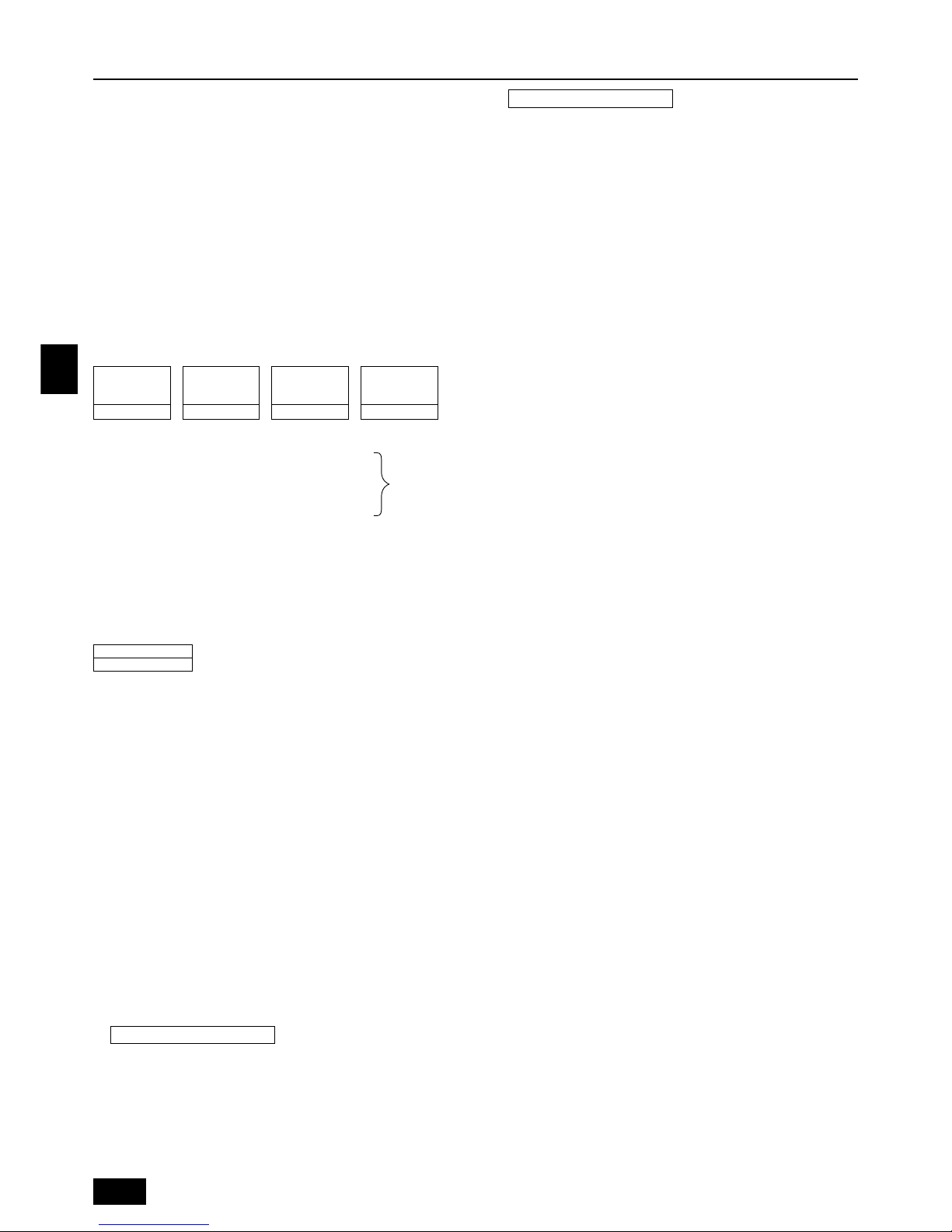
A : Outdoor Unit
B : First Branch
C : Indoor unit
D : Cap
4
[Fig. 4.0.1]
a, b, c, d, e (mm)
Î Model number Å Liquid pipe ı Gas pipe
20,25,32,40 ø6.35 ø12.7
50,63,71,80 ø9.52 ø15.88
100,125,140 ø9.52 ø19.05
200 ø12.7 ø25.4
250 ø12.7 ø28.58
<A>
A
L2
=
>
L1
=
>
(1)
<A> : Top view
<B> : Side view
<C> : When there is little space up to an obstruction
A : Front
B : No restrictions on wall height (left and right)
C : Air outlet guide (Procured at the site)
(mm)
L1 L2
450 450
AAFA
L1
=
>
L1
=
>
D : Must be open
E : Wall height (H)
F : No restrictions on wall height
7
7.2
[Fig. 7.2.1]
E
AA
DD
E
L
2
=
>
L
1
=
>
1000
=
>
E
D
E
AAAAA
L
1
=
>
L
1
=
>
L
1
=
>
L
1
=
>
L
1
=
>
L
2
=
>
E
AA
E
DD
1000
=
>
L2
=
>
L2
=
>
900
=
>
E
A
D
A
D
1000
=
>
1000
=
>
900
L
2
=
>
=
>
(5)
<C>
<B>(2)
C
45°
=
>
300
=
>
1000
=
>
(3) <A>
<B>
A
A
B
Hh
L
2
=
>
L
1
=
>
L
1
=
>
L
2
=
>
(4)
A
650
325
A
H
h
Hh
L
1
=
>
L
1
=
>
L
2
=
>
L
2
=
>
<A> <B>
6
[Fig. 6.1.1]
B
A
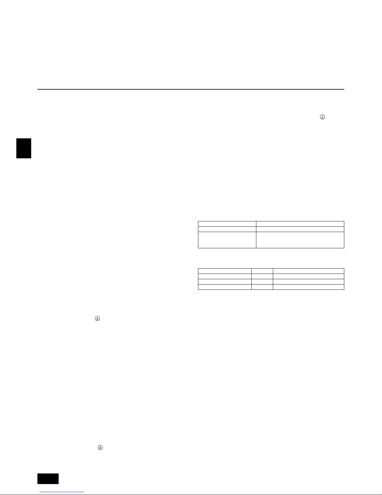
A : M10 anchor bolt procured at the site.
B : Corner is not seated.
[Fig. 5.0.1]
5
40°
=
<
7m
=
<
7m
=
<
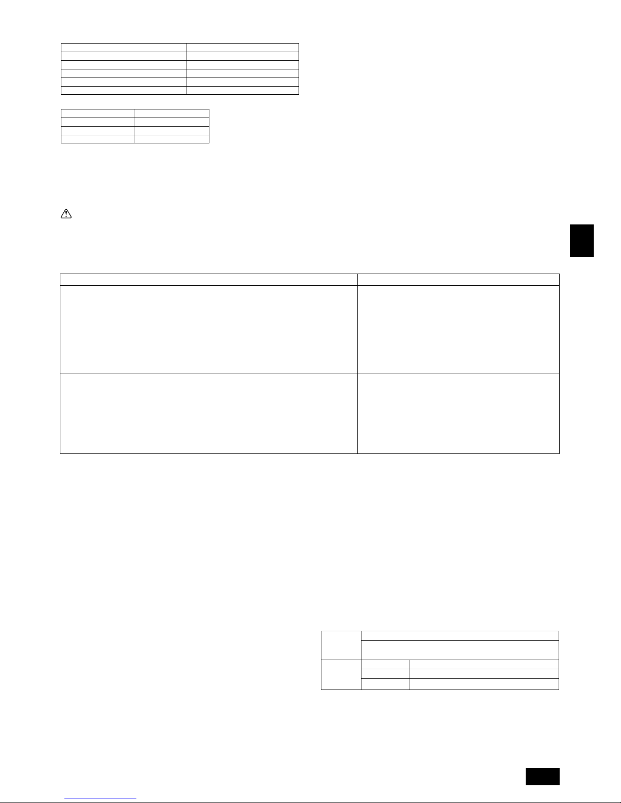
B, C, D (mm)
Ç Total capacity of indoor units Å Liquid pipe ı Gas pipe
~ 80 ø9.52 ø15.88
81 ~ 160 ø12.7 ø19.05
161 ~ ø12.7 ø25.4
‰ Downstream Unit Model Total Ï Branch Kit Model
~ 160 CMY-Y102S-F
161 ~ CMY-Y102L-F
Ì 4-Branching Header Ó 7-Branching Header È 10-Branching Header
CMY-Y104-F CMY-Y107-F CMY-Y1010-F
A (mm)
Å Liquid pipe ı Gas pipe
PUHY-P200 ø12.7 ø25.4
PUHY-P250 ø12.7 ø28.58
3
O
S
EE
O
S
I
K
J
H
G
F
A
B
C
D
[Fig. 8.2.3]
D
C
C
B
E
F
G
H
I
J
A
LO
HI
LO
HI
B
A
K
J
L
H
M
C
D
E
F
G
I
[Fig. 8.3.1]
[Fig. 8.3.3]
[Fig. 8.3.2]
8.3
8.2
A
8
[Fig. 8.2.4]
[Fig. 8.2.2]
L
M
1
3
A : Valve stem
B : Stopper pin
C : Packing (Accessory)
D : Connecting pipe (Accessory)
E : Open (Operate slowly)
F : Cap, copper packing
G : Service port
H : Flare nut
I : ø12.7
J : ø25.4 (PUHY-P200)
ø28.58 (PUHY-P250)
K : Field piping
L : Close-packed packing
M : Hollow packing
A : Nitrogen gas
B : To indoor unit
C : System analyzer
D : Lo Knob
E : Hi Knob
F : Ball valve
G : Liquid pipe
H : Gas pipe
I : To oil trap kit
J : Service port
<A> [Ball valve (gas side)]
(This figure shows the valve
in the fully open state.)
A : System analyzer
B : Lo Knob
C : Hi Knob
D : Ball valve
E : Liquid pipe
F : Gas pipe
G : Service port
H : Three-way joint
I : Valve
J : Valve
K : Cylinder
L : Scale
M : Vacuum pump
<B> [Ball valve (liquid side)]
A : Syphon pipe
In case of the cylinder having no syphon pipe.
O
S
O
S
[Fig. 8.2.1]
A : To oil trap kit
B : To indoor unit
C : Hollow Packing (Accessory)
D : Connecting pipe 1 (Accessory)
E : Service port
F : Flare nut (Accessory)
G : Cap (Accessory)
H : ø12.7
I : ø25.4 (PUHY-P200)
J : ø28.58 (PUHY-P250)
K : Close-packed packing (Accessory)
L : Connecting pipe 3 (Accessory)
M : Connecting pipe 4 (Accessory)
N : Connecting pipe 2 (Accessory)
O : ø25.4
P : Bolt M10 (Accessory)
<A> [Ball valve (gas side)]
(This figure shows the valve in
the close state.)
<B> [Ball valve (liquid side)]
(This figure shows the valve in
the close state.)
4
9.4
9
8.4
[Fig. 8.4.4]
[Fig. 8.4.3]
[Fig. 8.4.2]
C
A
B
D
E
[Fig. 8.4.1]
[Fig. 9.4.1]
BA
C
3N~380–415V
L
1, L2, L3, N, PE
BA
~220–240V
L, N, PE
E EDE E
[Fig. 9.2.1]
[Fig. 9.3.2]
B
A
D
C
E
E
E
D
A
B
D
F
G
B
<D> Floor (waterproofing)
E
I
B
<C> Outer wall (exposed)
A B
<A> Inner wall (concealed)
A B
D
C
<B> Outer wall
F
H
D
B
G
<E> Roof pipe shaft
I
A
J
1m1m
<F> Penetrating portion on fire
limit and boundary wall
9.3
9.2
[Fig. 9.3.1]
AB
L1 L2 L3 N M1M2 M1M2 S
TB3 TB7
TB1
A : Steel wire B : Piping
C : Asphaltic oily mastic or asphalt
D : Heat insulation material A
E : Outer covering B
A : Liquid pipe B : Gas pipe
C : Electric wire D : Finishing tape
E : Insulater
A : Sleeve B : Heat insulating material
C : Lagging D : Caulking material
E : Band F : Waterproofing laye
G : Sleeve with edge H : Lagging material
I : Mortar or other incombustible caulking
J : Incombustible heat insulation material
A : Power source
B : Transmission line
A : Group 1
B : Group 3
C : Group 5
D : Shielded Wire
E : Sub Remote
Controller
A : Switch (Breakers for Wiring and Current Leakage)
B : Breakers for Current Leakage
C : Outdoor Unit
D : Pull Box
E : Indoor Unit
A B C
E
D
M1 M2
M1 M2 S
TB7
TB3
IC
(51)
M1 M2 S
TB5
RC
(01)
IC
M1 M2 S
TB5
(02)
IC
M1 M2 S
TB5
(04)
IC
M1 M2 S
TB5
(03)
IC
M1 M2 S
TB5
(05)
IC
M1 M2 S
TB5
(07)
IC
M1 M2 S
TB5
(06)
L
2
L
1
(101)
RC
(105)
RC
(103)
RC
(155)
OC
M1 M2
M1 M2 S
TB7
TB3
(52)
OC
r
3
M1M2S
Power Supply
Unit
M1M2S
MJ103
L
3
L
6
L
7
L
4
L
5
r
2
r
4
r
1
AB AB AB
AB
A B C
E
D
M1 M2
M1 M2 S
TB7
TB3
IC
(51)
M1 M2 12S
TB5 TB15
12
TB15
12
TB15
12
TB15
12
TB15
12
TB15
MA
(01)
IC
M1 M2 S
TB5
(02)
IC
M1 M2 S
TB5
(04)
IC
M1 M2 S
TB5
(03)
IC
M1 M2 S
TB5
(05)
IC
M1 M2 S
TB5
(07)
IC
M1 M2 S
TB5
(06)
L
2
L
1
MAMAMA
OC
M1 M2
M1 M2 S
TB7
TB3
(52)
OC
c
1
c
4
c
3
S
Power Supply
Unit
S
MJ103
L
3
L
6
L
7
L
4
c
2
ABABAB
AB
M1M2
M1M2
c
2
c
1
c
1
c
2
5
GB
D
F
INL
E
PGRRUTR
Contents
1. Safety precautions
1.1. Before installation and electric work
s Before installing the unit, make sure you read all the “Safety
precautions”.
s The “Safety precautions” provide very important points re-
garding safety. Make sure you follow them.
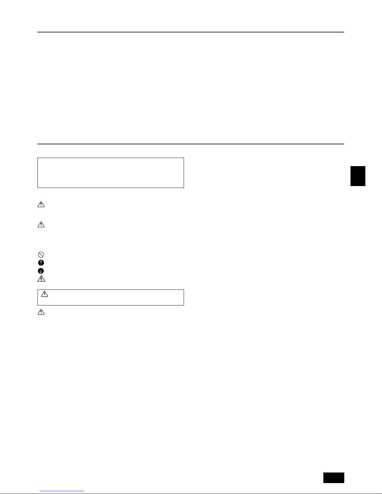
Symbols used in the text
Warning:
Describes precautions that should be observed to prevent danger of injury
or death to the user.
Caution:
Describes precautions that should be observed to prevent damage to the
unit.
Symbols used in the illustrations
: Indicates an action that must be avoided.
: Indicates that important instructions must be followed.
: Indicates a part which must be grounded.
: Beware of electric shock. (This symbol is displayed on the main unit label.)
<Color: yellow>
Warning:
Carefully read the labels affixed to the main unit.
Warning:
• Ask the dealer or an authorized technician to install the air conditioner.
- Improper installation by the user may result in water leakage, electric shock,
or fire.
• Install the unit at a place that can withstand its weight.
- Inadequate strength may cause the unit to fall down, resulting in injuries.
• Use the specified cables for wiring. Make the connections securely so
that the outside force of the cable is not applied to the terminals.
- Inadequate connection and fastening may generate heat and cause a fire.
• Prepare for strong winds and earthquakes and install the unit at the specified place.
- Improper installation may cause the unit to topple and result in injury.
• Always use an filter and other accessories specified by Mitsubishi Electric.
- Ask an authorized technician to install the accessories. Improper installation
by the user may result in water leakage, electric shock, or fire.
• Never repair the unit. If the air conditioner must be repaired, consult the
dealer.
- If the unit is repaired improperly, water leakage, electric shock, or fire may
result.
• Do not touch the heat exchanger fins.
- Improper handling may result in injury.
• If refrigerant gas leaks during installation work, ventilate the room.
- If the refrigerant gas comes into contact with a flame, poisonous gases will
be released.
• Install the air conditioner according to this Installation Manual.
- If the unit is installed improperly, water leakage, electric shock, or fire may
result.
• Have all electric work done by a licensed electrician according to “Electric Facility Engineering Standard” and “Interior Wire Regulations”and
the instructions given in this manual and always use a special circuit.
- If the power source capacity is inadequate or electric work is performed im-
properly, electric shock and fire may result.
• Securely install the outdoor unit terminal cover (panel).
- If the terminal cover (panel) is not installed properly, dust or water may enter
the outdoor unit and fire or electric shock may result.
• When installing and moving the air conditioner to another site, do not
charge it with a refrigerant different from the refrigerant specified on the
unit.
- If a different refrigerant or air is mixed with the original refrigerant, the refrig-
erant cycle may malfunction and the unit may be damaged.
• If the air conditioner is installed in a small room, measures must be taken
to prevent the refrigerant concentration from exceeding the safety limit if
the refrigerant should leak.
- Consult the dealer regarding the appropriate measures to prevent the safety
limit from being exceeded. Should the refrigerant leak and cause the safety
limit to be exceeded, hazards due to lack of oxygen in the room could result.
• When moving and reinstalling the air conditioner, consult the dealer or
an authorized technician.
- If the air conditioner is installed improperly, water leakage, electric shock, or
fire may result.
• After completing installation work, make sure that refrigerant gas is not
leaking.
- If the refrigerant gas leaks and is exposed to a fan heater, stove, oven, or
other heat source, it may generate noxious gases.
• Do not reconstruct or change the settings of the protection devices.
- If the pressure switch, thermal switch, or other protection device is shorted
and operated forcibly, or parts other than those specified by Mitsubishi Electric are used, fire or explosion may result.
• To dispose of this product, consult your dealer.
• The installer and system specialist shall secure safety against leakage
according to local regulation or standards.
- Following standards may be applicable if local regulation are not available.
• Pay special attention to the place of installation, such as a basement, etc.
where refrigeration gas can accumulate, since refrigeration is heavier
than the air.
1.2. Precautions for devices that use R407C
refrigerant
• Use refrigerant piping made of phosphorus deoxidized copper and copper alloy seamless pipes and tubes. In addition, be sure that the inner
and outer surfaces of the pipes are clean and free of hazardous sulphur,
oxides, dust/dirt, shaving particles, oils, moisture, or any other contaminant.
- Contaminants on the inside of the refrigerant piping may cause the refriger-
ant residual oil to deteriorate.
• Store the piping to be used during installation indoors and keep both
ends of the piping sealed until just before brazing. (Store elbows and
other joints in a plastic bag.)
- If dust, dirt, or water enters the refrigerant cycle, deterioration of the oil and
compressor trouble may result.
• Use ester oil, ether oil or alkylbenzene (small amount) as the refrigerator
oil to coat flares and flange connections.
- The refrigerator oil will degrade if it is mixed with a large amount of mineral
oil.
• Use liquid refrigerant to fill the system.
- If gas refrigerant is used to seal the system, the composition of the refriger-
ant in the cylinder will change and performance may drop.
• Do not use a refrigerant other than R407C.
- If another refrigerant (R22, etc.) is mixed with R407C, the chlorine in the
refrigerant may cause the refrigerator oil to deteriorate.
• Use a vacuum pump with a reverse flow check valve.
- The vacuum pump oil may flow back into the refrigerant cycle and cause the
refrigerator oil to deteriorate.
1. Safety precautions ...................................................................................... 5
1.1. Before installation and electric work .......................................... 5
1.2. Precautions for devices that use R407C refrigerant .................. 5
1.3. Caution concerning equipment used for replacement ............... 6
1.4. Before installation ...................................................................... 7
1.5. Before installation - electrical work ............................................ 7
1.6. Before starting the test run ........................................................ 7
2. Specifications .............................................................................................. 8
3. Confirmation of parts attached ................................................................... 8
4. Space required around unit ........................................................................ 8
5. Lifting method and weight of product .......................................................... 8
6. Installation of unit ........................................................................................ 9
6.1. Installation ................................................................................. 9
7. Refrigerant piping installation ..................................................................... 9
7.1. Caution ...................................................................................... 9
7.2. Refrigerant piping system.......................................................... 9
8. Additional Refrigerant Charge .................................................................. 10
8.1. Calculation of Additional Refrigerant Charge .......................... 10
8.2. Precautions concerning piping connection and
valve operation ........................................................................ 10
8.3. Airtight test, evacuation, and refrigerant charging ................... 11
8.4. Thermal insulation of refrigerant piping ................................... 11
9. Wiring ........................................................................................................ 12
9.1. Caution .................................................................................... 12
9.2. Control box and connecting position of wiring ......................... 12
9.3. Wiring transmission cables...................................................... 12
9.4. Wiring of main power supply and equipment capacity ............ 13
10. Test run ..................................................................................................... 14
10.1. The following phenomena do not represent trouble
(emergency) ............................................................................ 14
11. Rating plate ............................................................................................... 14
6
GB
D
F
INL
E
PGRRUTR
• Do not use the following tools that are used with conventional refrigerants.
(Gauge manifold, charge hose, gas leak detector, reverse flow check valve,
refrigerant charge base, refrigerant recovery equipment)
- If the conventional refrigerant and refrigerator oil are mixed in the R407C,
the refrigerant may deteriorated.
- If water is mixed in the R407C, the refrigerator oil may deteriorate.
- Since R407C does not contain any chlorine, gas leak detectors for conven-
tional refrigerants will not react to it.
• Do not use a charging cylinder.
- Using a charging cylinder may cause the refrigerant to deteriorate.
• Be especially careful when managing the tools.
- If dust, dirt, or water gets into the refrigerant cycle, the refrigerant may dete-
riorate.
1.3. Caution concerning equipment used for
replacement
• Do not operate the valve before conducting mineral oil recovery operation.
- Operating valves before conducting mineral oil recovery operation may cause
a deterioration in the performance of mineral oil recovery.
• For mineral oil recovery operation, the system controller and MA remote
controller may be required to be remove sometimes.
- Improper handling can lead to an inability to perform oil recovery operation.
- For removal, follow the instruction displayed on the PC for mineral recovery.
- Mount the controllers again after finishing the oil recovery operation.
• Observe a safe distance from the indoor unit fan, which runs during the
mineral oil recovery operation.
- Working in the surrounding of the indoor unit fan can cause personal injury.
• Record the quantity of refrigerant replenished.
(Enter into the column for replenished refrigerant quantity on the label of
the indoor unit.)
- Missing the description may deteriorate the performance of mineral oil re-
covery.
- Malfunction or poor cooling/heating may also be caused.
• During the mineral oil recovery operation, an error display may be shown
on the remote controller or system controller.
- When an error display was shown during mineral oil recovery operation, re-
set the error display after finishing the operation.
• To conduct the refrigerant recovery/evacuation of the inside of exiting
piping, choose tools only used with R407C e.g. charging hose.
- Using a charging hose for R407C causes it to mix the conventional refriger-
ating machine oil leading to the deterioration of refrigerating machine oil.
Items to be observed
• Please note that our Corporation is not liable to the reliability of existing piping, wiring and power
system for reuse (in relation with the gas leak of piping, partially defective/disconnection of wiring, deteriorated insulation, characteristic faults due to worn out system).
• For limitation on the refrigerant piping and applicable piping diameter, check the existing piping
for reuse in accordance with the specified check sheet by referring products catalogs and manuals for judgement to reuse.
• If vapor condensation was found in the past, check the thermal insulation.
• For a portion suffered by condensation dripping, check the deterioration of the insulation, and
repair the insulation materials if required.
• When the copper piping is seriously deteriorated, do not use parts with verdigris or black spots.
• For reusing the existing control wiring between the outdoor unit, and remote controller, check the
wire type, size or the like based on the check sheet to judge the possibility.
• Even when the above does not meet the item on the check sheet, existing wiring may be reused
depending on the number of connecting indoor units and piping length. Ask us for detail.
• For the power source system employ the voltage and number of phase meeting the outdoor unit,
indoor unit and heat storage unit, and adopt the breaker capacity and wiring size based on the
power source wiring connection diagram.
• When the existing power source system (including the power source wiring) is used, check the
system for deterioration and damages.
• Check the refrigerating machine oil used in the existing system. (As is found at the oil inspection,
if the refrigerating machine oil used in the existing system is mineral oil, use the ester oil sampling kit for inspection.
• When the length of piping for reuse is unknown, additional refrigerant charge is to be calculated
based on the quantity of recovered refrigerant. For this reason, you are kindly requested to
recover all refrigerant inside the existing outdoor/indoor units and extended piping to check and
record the quantity, (The standard of additional refrigerant is (Quantity of R22 recovered - Charged
quantity of existing outdoor unit + 3kg). Adjust the refrigerant quantity after mineral oil recovery
operation.)
■ Outdoor unit
• Confirm the space around the outdoor unit.
(Verifying the installation space of the oil trap kit)
■ Turn the power sources on, and confirm the normality of the system
• Check the remote controller or outdoor unit for error display.
• Run the indoor unit for fan operation after turning the remote controller on, and check the air
feeding and direction.
Do not run the compressor until finishing the mineral oil recovery operation.
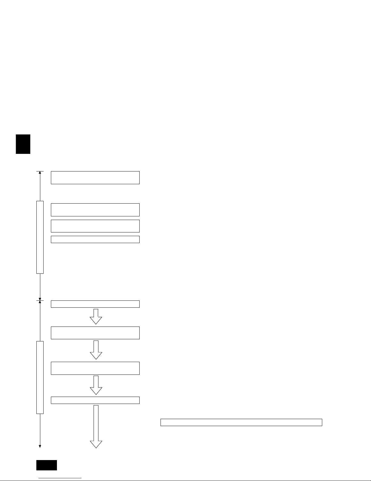
Caution to REPLACE MULTI Installation Work
Flow of Installation work in the field
Recovering the refrigerant of old system
Removing the outdoor/indoor units, remote
controllers, etc.
Installing the outdoor/indoor units, remote controllers, etc., and executing electrical work
Setting the address checking the system
Confirming the possibility of existing power
source system for reuse
Confirming the objective range for replacing
Confirming the possibility of existing control
wiring for reuse
Confirming the possibility of existing refrigerant piping for reuse
During local installation work
Before local installation work
7
GB
D
F
INL
E
PGRRUTR
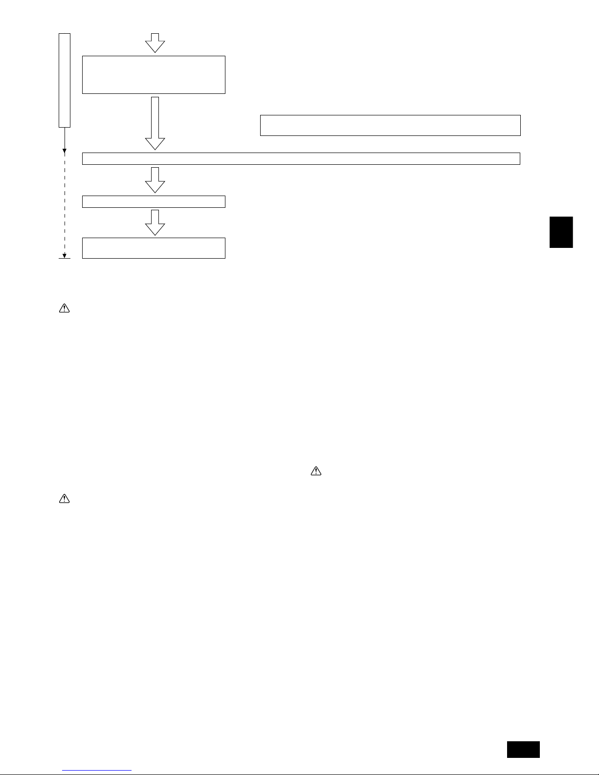
It is necessary to charge refrigerant in a rated quantity and adjust the quantity. Be sure to execute
when the piping length is unknown.
For detail, consult the agent of your dealer.
■ Mount the valve to the field piping (extended piping). (The ball valve is being attached to the
outdoor unit.)
■ Execute an airtight test to check the existing piping for deterioration or leaking.
■ Calculate the quantity required by the extended piping, and charge the additional refrigerant.
Make sure to enter the value in the additional refrigerant charge column on the label of combined
outdoor unit being pasted on the outdoor unit.
Executing the piping work (mounting of ball
valve).
Air tightening and evacuating the existing piping and charging refrigerant
Operating mineral oil recovery
Executing test run and adjustment (for final
verification of operation).
During local installation work
Without applying any operation, keep the ball valves of the outdoor unit closed before
mineral oil recovery operation.
1.4. Before installation
Caution:
• Do not install the unit where combustible gas may leak.
- If the gas leaks and accumulates around the unit, an explosion may result.
• Do not use the air conditioner where food, pets, plants, precision instruments, or artwork are kept.
- The quality of the food, etc. may deteriorate.
• Do not use the air conditioner in special environments.
- Oil, steam, sulfuric smoke, etc. can significantly reduce the performance of
the air conditioner or damage its parts.
• When installing the unit in a hospital, communication station, or similar
place, provide sufficient protection against noise.
- Inverter equipment, private power generator, high-frequency medical equip-
ment, or radio communication equipment may cause the air conditioner to
operate erroneously, or fail to operate. On the other hand, the air conditioner
may affect such equipment by creating noise that disturbs medical treatment
or image broadcasting.
• Do not install the unit on a structure that may cause leakage.
- When the room humidity exceeds 80 % or when the drain pipe is clogged,
condensation may drip from the indoor unit. Perform collective drainage work
together with the outdoor unit, as required.
1.5. Before installation - electrical work
Caution:
• Ground the unit.
- Do not connect the ground wire to gas or water pipes, lightning rods, or
telephone ground lines. Improper grounding may result in electric shock.
• The reverse phase of L lines (L
1, L2, L3) can detected (Error cord: 4103),
but the reverse phase of L lines and N line can not be detected.
- Some electric parts may be damaged when power is supplied during miss
wiring.
• Install the power cable so that tension is not applied to the cable.
- Tension may cause the cable to break and generate heat and cause a fire.
• Install a leak circuit breaker, as required.
- If a leak circuit breaker is not installed, electric shock may result.
• Use power line cables of sufficient current carrying capacity and rating.
- Cables that are too small may leak, generate heat, and cause a fire.
• Use only a circuit breaker and fuse of the specified capacity.
- A fuse or circuit breaker of a larger capacity, a steel or copper wire may result
in a general unit failure or fire.
• Do not wash the air conditioner units.
- Washing them may cause an electric shock.
• Be careful about that the installation base is not damaged by long use.
- If the damage is left uncorrected, the unit may fall and cause personal injury
or property damage.
• Install the drain piping according to this Installation Manual to ensure
proper drainage. Wrap thermal insulation around the pipes to prevent
condensation.
- Improper drain piping may cause water leakage causing damage to furniture
and other possessions.
• Be very careful about transporting the product.
- One person should not carry the product as it weighs more than 20 kg.
- Some products use PP bands for packaging. Do not use any PP bands as a
means of transportation. It is dangerous.
- Do not touch the heat exchanger fins. Doing so may cut your fingers.
- When transporting the outdoor unit, support it at the specified positions on
the unit base. Also support the outdoor unit at four points so that it cannot
slip sideways.
• Safely dispose of the packing materials.
- Packing materials, such as nails and other metal or wooden parts, may cause
stabs or other injuries.
- Tear apart and throw away plastic packaging bags so that children will not
play with them. If children play with a plastic bag which was not torn apart,
they face the risk of suffocation.
1.6. Before starting the test run
Caution:
• Turn on the power at least 12 hours before starting operation.
- Starting operation immediately after turning on the main power switch can
result in irreversible damage to internal parts. Keep the power switch turned
on during the operational season.
• Do not touch the switches with wet fingers.
- Touching a switch with wet fingers can cause electric shock.
• Do not touch the refrigerant pipes during and immediately after operation.
- During and immediately after operation, the refrigerant pipes may be hot or
cold, depending on the condition of the refrigerant flowing through the refrigerant piping, compressor, and other refrigerant cycle parts. Your hands may
suffer burns or frostbite if you touch the refrigerant pipes.
• Do not operate the air conditioner with the panels and guards removed.
- Rotating, hot, or high-voltage parts can cause injuries.
• Do not turn off the power immediately after stopping operation.
- Always wait at least five minutes before turning off the power. Otherwise,
water leakage and trouble may occur.
• Do not touch the surface of the compressor during servicing.
- If unit is connected to the supply and not running, crank case heater at com-
pressor base is operating.
Enter required items in the request form of REPLACE MULTI mineral oil recovery work.
8
GB
D
F
INL
E
PGRRUTR
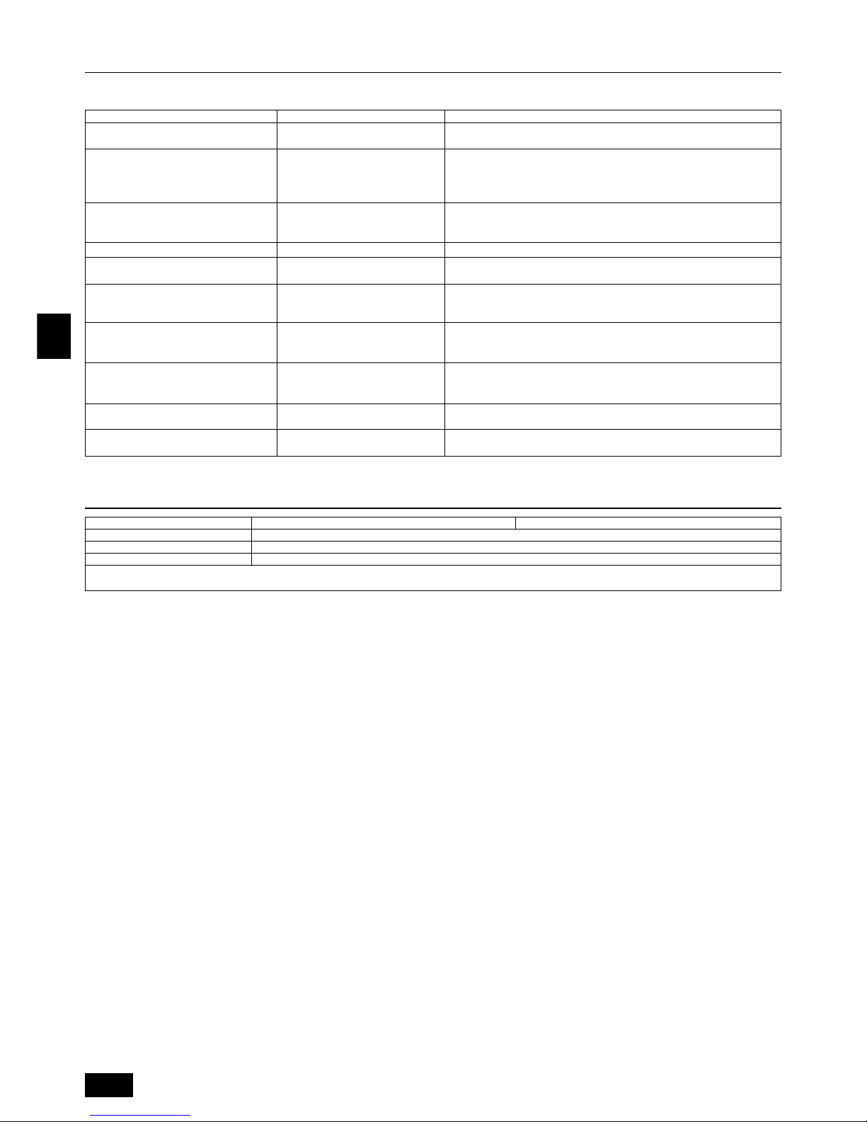
2. Specifications
Model
Noise level
External static pressure
Indoor units
Total capacity
Model / Quantity
Operation temperature
PUHY-P200 PUHY-P250
56 dB <A> 57 dB <A>
0 Pa
50 ~ 130 %
20 ~ 250 / 1 ~ 13 20 ~ 250 / 1 ~ 16
Cooling mode:– 5 °CDB ~ 43 °CDB (0 °CDB ~ 43 °CDB with outdoor unit at lower position)
Heating mode: – 15 °CWB ~ 15.5 °CWB
3. Confirmation of parts attached
1 Wiring mounting board × 1 2 Conduit mounting plate (ø40) × 1 3 Conduit mounting plate (ø33) × 1
4 Conduit mounting plate (ø27) × 1 5 Tapping screw M4 × 6
6 Connecting pipe 1 × 3 (Used to connect to the oil trap kit when recovering mineral oil and to connect piping after mineral oil recovery.)
7 Packing 1 (inside ø23, outsideø35) × 2 (Used to connect to the oil trap kit when recovering mineral oil and to connect piping after mineral oil recovery.)
8 Packing 2 (close-packed packing) × 1 (Used to isolate the refrigerant circuit connected to the indoor unit.)
9 Flare nut × 2
0 Cap × 1
A Connecting pipe 2 (Used when the pipe diameter of existing onsite pipes is ø25.4 mm.)
B Connecting pipe 3 (For connection to the oil trap kit)
C Connecting pipe 4 (For connection to the oil trap kit)
D Bolt M10 × 4 E Cover F Ball valve (Liquid side)
G Ball valve (Gas side)
4. Space required around unit
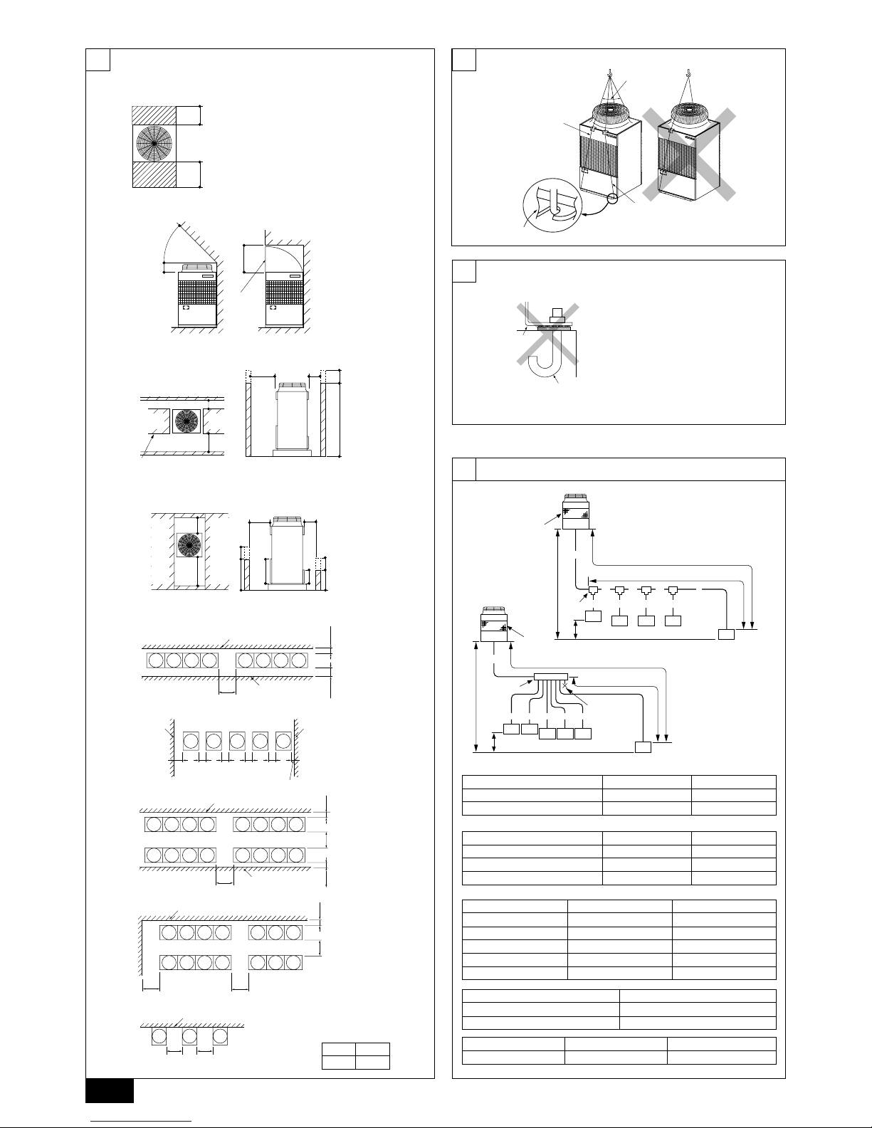
[Fig. 4.0.1] (P.2)
<A> Top view <B> Side view
<C> When there is little space up to an obstruction
A Front B No restrictions on wall height (left and right)
C Air outlet guide (Procured at the site) D Must be open
E Wall height (H) F No restrictions on wall height
(mm)
L1 L2
450 450
(1) Basic space required
Taking servicing, etc. from the rear into account, a space of about 450 mm should
be provided, the same as at the front.
(2) When there is an obstruction above the unit
(3) When inlet air enters from right and left sides of unit
• Wall heights (H) of the front and the rear sides shall be within overall height of
unit.
• When the total height is exceeded, add the “h” dimension of the Fig. 4.0.1 to L1
and L2.
(4) When unit is surrounded by walls
Note:
• Wall heights (H) of the front and the back sides shall be within overall
height of unit.
• If the panel height is exceeded, add the “h” dimension of the Fig. 4.0.1 to
L1 and L2.
(mm)
L1 L2
450 450
Example: When h is 100 mm,
the L
1 dimension becomes 450 + 100 = 550 mm.
(5) Collective installation and continuous installation
• Space required for collective installation and continuous installation:
When installing several units, leave the space between each block considering
passage for air and people.
• Open in two directions.
• In case wall height (H) exceeds overall height of unit, add “h” dimension (h =
wall height <H> – overall height of unit) to * marked dimension.
• If there is a wall at both the front and the rear of the unit, install up to four units
consecutively in the side direction and provide a space of 1000 mm or more as
inlet space/passage space for each four units.
5. Lifting method and weight of product
[Fig. 5.0.1] (P.2)
Caution:
Be very careful to carry product.
- Do not have only one person to carry product if it weighs more than 20 kg.
- PP bands are used to pack some products. Do not use them as a mean for transportation because they are dangerous.
- Do not touch heat exchanger fins with your bare hands. Otherwise you cut your hands.
- Tear plastic packaging bag and scrap it so that children cannot play with it. Otherwise plastic packaging bag may suffocate children to death.
- When carrying outdoor unit, be sure to support it at four points. Carrying with 3-point support may make outdoor unit unstable, resulting in it falling.
9
GB
D
F
INL
E
PGRRUTR
7. Refrigerant piping installation
(1) Before mineral oil recovery
In order to perform vacuum drawing and ensure the gas-tightness of the refrigerant pipes connected to the indoor unit, it is necessary to fit a valve (supplied with
outdoor unit). Make the liquid side a flare connection and the gas side a brazed
connection. (If the pipe diameter of the current onsite pipe is ø25.4 mm, connect
using the connecting pipe 2 (supplied with the outdoor unit)).
CAUTION:
• The refrigerant pipes connected to the indoor unit and the outdoor unit
will be connected to the oil trap kit when recovering the mineral oil and
so do not connect the pipes.
• Allow for the connection to the outdoor unit and oil trap kit when installing the valve.
(The total length of the piping should be 5m or less.)
(2) After mineral oil recovery
Connecting the piping is a terminal-branch type in which refrigerant piping from
the outdoor unit is branched at the terminal and connected to each of the indoor
units.
The method of connection consists of flare connections at the indoor units, flange
connections for the piping of the outdoor unit and flare connections for the liquid
piping. Note that the branched sections are brazed.
Warning:
Always use extreme care to prevent the refrigerant gas from leaking while
using fire or flame. If the refrigerant gas comes in contact with the flame
from any source, such as a gas stove, it breaks down and generates a poisonous gas which can cause gas poisoning. Never weld in an unventilated
room. Always conduct an inspection for gas leakage after installation of the
refrigerant piping has been completed.
7.1. Caution
1 Use the following materials for refrigeration piping.
• Material: Use refrigerant piping made of phosphorus deoxidized copper.
In addition, be sure that the inner and outer surfaces of the pipes are clean
and free of hazardous sulphur, oxides, dust/dirt, shaving particles, oils,
moisture, or any other contaminant.
2 Commercially available piping often contains dust and other materials. Always
blow it clean with a dry inert gas.
3 Use care to prevent dust, water or other contaminants from entering the piping
during installation.
4 Reduce the number of bending portions as much as possible, and make bend-
ing radius as big as possible.
5 Always observe the restrictions on the refrigerant piping (such as rated length,
the difference between high/low pressures, and piping diameter). Failure to do
so can result in equipment failure or a decline in heating/cooling performance.
6 Replace multi will stop due to an abnormality due to excessive or insufficient
coolant. At such a time, always properly charge the unit. When servicing,
always check the notes concerning pipe length and amount of additional refrigerant at both locations, the refrigerant volume calculation table on the back
of the service panel and the additional refrigerant section on the labels for the
combined number of indoor units. If the refrigerant could not be charged to the
prescribed amount, show the insufficient portion on the labeling.
7 Use liquid refrigerant to fill the system.
8 Never use refrigerant to perform an air purge. Always evacuate using a vacuum
pump.
9 Always insulate the piping properly. Insufficient insulation will result in a de-
cline in heating/cooling performance, water drops from condensation and other
such problems.
0 When connecting the refrigerant piping, make sure the ball valve of the out-
door unit is completely closed (the factory setting) and do not operate it until
the refrigerant piping for the outdoor and indoor units has been connected and
the mineral oil recovery operation has been completed.
A Always use a non-oxidizing brazing material for brazing the parts. If a non-
oxidizing brazing material is not used, it could cause clogging or damage to
the compressor unit.
B Never perform outdoor unit piping connection work when it is raining.
Warning:
When installing and moving the unit, do not charge it with refrigerant other
than the refrigerant specified on the unit.
- Mixing of a different refrigerant, air, etc. may cause the refrigerant cycle to malfunction and result in severe damage.
Caution:
• Use a vacuum pump with a reverse flow check valve.
- If the vacuum pump does not have a reverse flow check valve, the vacuum
pump oil may flow back into the refrigerant cycle and cause deterioration of
the refrigerator oil and other trouble.
• Do not use the tools shown below used with conventional refrigerant.
(Gauge manifold, charge hose, gas leak detector, check valve, refrigerant
charge base, vacuum gauge, refrigerant recovery equipment)
- Mixing of conventional refrigerant and refrigerator oil may cause the refrig-
erator oil to deteriorate.
- Mixing of water will cause the refrigerator oil to deteriorate.
- R407C refrigerant does not contain any chlorine. Therefore, gas leak detec-
tors for conventional refrigerants will not react to it.
• Manage the tools more carefully than normal.
- If dust, dirt, or water gets in the refrigerant cycle, the refrigerator oil will dete-
riorate.
• Refer to the Installation manual concerning whether you can use an existing refrigerant piping.
- Depending on the type, old refrigeration oil in the existing piping could re-
duce the effectiveness of mineral oil recovery and cause the new refrigeration oil to deteriorate.
- If you use the existing piping in a way that is outside the scope of the piping
specifications (for example, pipe diameter, pipe length and vertical interval),
it will reduce the effectiveness of mineral oil recovery and will cause the new
refrigeration oil to deteriorate.
• Store the piping to be used during installation indoors and keep both
ends of the piping sealed until just before brazing.
- If dust, dirt, or water gets into the refrigerant cycle, the oil will deteriorate and
the compressor may fail.
• Do not use a charging cylinder.
- Using a charging cylinder may cause the refrigerant to deteriorate.
• Do not use special detergents for washing piping.
7.2. Refrigerant piping system
Connection Example
[Fig. 7.2.1] (P.2)
Å Liquid pipe ı Gas pipe
Ç Total capacity of indoor units Î Model number
‰ Downstream Unit Model Total Ï Branch Kit Model
Ì 4-Branching Header Ó 7-Branching Header
¬ 10-Branching Header
A Outdoor Unit B First Branch
C Indoor unit D Cap
• The pipe of ø28.58 mm can be used for the gas pipe of PUHY-P200.
6. Installation of unit
6.1. Installation
[Fig. 6.1.1] (P.2)
A M10 anchor bolt procured at the site. B Corner is not seated.
• Fix unit tightly with bolts so that unit will not fall down due to earthquake or gust
of wind.
• Use concrete or angle bracket for foundation of unit.
• Vibration may be transmitted to the installation section and noise and vibration
may be generated from the floor and walls, depending on the installation conditions. Therefore, provide ample vibrationproofing (cushion pads, cushion
frame, etc.).
• Be sure that the corners are firmly seated. If the corners are not firmly seated,
the installation feet may be bent.
Warning:
• Be sure to install unit in a place strong enough to withstand its weight.
Any lack of strength may cause unit to fall down, resulting in a personal
injury.
• Have installation work in order to protect against a strong wind and earthquake.
Any installation deficiency may cause unit to fall down, resulting in a
personal injury.
When building the foundation, give full attention to the floor strength, drain water
disposal <during operation, drain water flows out of the unit>, and piping and wiring routes.
Down piping and down wiring precautions
When down piping and down wiring are performed, be sure that foundation and
base work does not block the base through holes. When down piping is performed,
make the foundation at least 100 mm high so that the piping can pass under the
bottom of the unit.
10
GB
D
F
INL
E
PGRRUTR
8. Additional Refrigerant Charge
Connecting to the oil trap kit side
1 Braze the ball valve on the gas side.
2 Inser t the packing, consisting of rubber bushing with membrane, and fit the
connecting pipe with flange to isolate the refrigerant circuit.
• When the valve is open, it obstructs the mineral oil recovery operation so this
valve must be in the closed position.
• Determine the amount of additional refrigerant charge by using the formula,
and charge refrigerant additionally through the service port after completing
piping connection work.
• Refer to “(2) After mineral oil recovery” for the required tightening torque.
(2) After mineral oil recovery
• Conduct piping connection and valve operation accurately.
• The gas side connecting pipe is assembled in factory before shipment.
1 For brazing to the connecting pipe with flange, remove the connecting pipe
with flange from the ball valve, and braze it outside of the unit.
2 During the time when removing the connecting pipe with flange, remove
the seal attached on the rear side of this sheet and paste it onto the flange
surface of the ball valve to prevent the entry of dust into the valve.
3 The refrigerant circuit is closed with a round, close-packed packing upon
shipment to prevent gas leak between flanges. As no operation can be
done under this state, be sure to replace the packing with the hollow packing attached at the piping connection.
4 At the mounting of the hollow packing, wipe off dust attached on the flange
sheet surface and the packing. Coat refrigerating machine oil (Ester oil,
ether oil or alkylbenzene [small amount]) onto both surfaces of the packing.
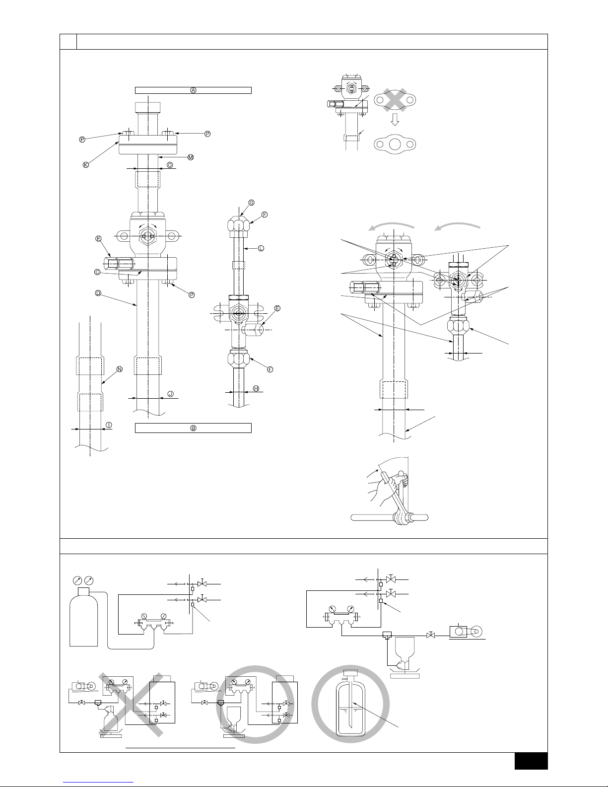
[Fig. 8.2.2] (P.3)
• After evacuation and refrigerant charge, ensure that the handle is fully open. If
operating with the valve closed, abnormal pressure will be imparted to the
high- or low-pressure side of the refrigerant circuit, giving damage to the compressor, four-way valve, etc.
• Determine the amount of additional refrigerant charge by using the formula,
and charge refrigerant additionally through the service port after completing
piping connection work.
• After completing work, tighten the service port and cap securely not to generate gas leak.
[Fig. 8.2.3] (P.3)
<A> [Ball valve (gas side)] (This figure shows the valve in the fully open state.)
<B> [Ball valve (liquid side)]
A Valve stem
[Fully closed at the factory, when connecting the piping, when evacuating, and
when charging additional refrigerant. Open fully after the operations above are
completed.]
B Stopper pin [Prevents the valve stem from turning 90° or more.]
C Packing (Accessory)
[Manufacturer: Nichiasu corporation]
[Type: T/#1991-NF]
D Connecting pipe (Accessory)
[Use packing and securely install this pipe to the valve flange so that gas leakage
will not occur. (Tightening torque: 25 N·m) Coat both surfaces of the packing with
refrigerating machine oil. (Ester oil, ether oil or alkylbenzene [small amount])]
E Open (Operate slowly)
F Cap, copper packing
[Remove the cap and operate the valve stem. Always reinstall the cap after operation is completed. (Valve stem cap tightening torque: 25 N·m or more)]
G Service port
[Use this port to evacuate the refrigerant piping and add an additional charge at
the site.
Open and close the port using a double-ended wrench.
Always reinstall the cap after operation is completed. (Service port cap tightening
torque: 14 N·m or more)]
H Flare nut
[Tightening torque: 55 N·m
Loosen and tighten this nut using a double-ended wrench.
Coat the flare contact surface with refrigerating machine oil (Ester oil, ether oil or
alkylbenzene [small amount])]
I ø12.7
J ø25.4 (PUHY-P200)
ø28.58 (PUHY-P250)
K Field piping
[Braze to the connecting pipe. (When brazing, use unoxidized brazing.)]
L Close-packed packing
M Hollow packing
At the time of shipping, the outdoor unit is charged with the refrigerant. As this
charge does not include the amount needed for extended piping, additional charging for each refrigerant line will be required on site. Note that the method used for
calculating the additional refrigerant charge for a Replace Multi is different to that
used for the Y Series. In order that future servicing may be properly provided,
always keep a record of the size and length of each refrigerant line and the amount
of additional charge by writing it in the space provided on the outdoor unit.
8.1. Calculation of Additional Refrigerant
Charge
• Calculate the amount of additional charge based on the length of the piping
extension and the size of the refrigerant line.
• Use the table to the right as a guide to calculating the amount of additional
charging and charge the system accordingly.
• If the calculation results in a fraction of less than 0.1 kg, round up to the next
0.1 kg. For example, if the result of the calculation was 12.62 kg, round the
result up to 12.7 kg.
<Additional Charge>
At the
conditions
below:
<Example>
Indoor 1: 40 A: ø12.7 40 m a: ø6.35 10 m
2: 100 B: ø12.7 10 m b: ø9.52 5 m
3: 40 C: ø12.7 15 m c: ø6.35 10 m
4: 32 D: ø12.7 10 m d: ø6.35 10 m
5: 63 e: ø9.52 10 m
The total length of each liquid line is as follows:
ø12.7: A + B + C + D = 40 + 10 + 15 + 10 = 75 m
ø9.52: b + e = 5 + 10 = 15 m
ø6.35: a + c + d = 10 + 10 + 10 = 30 m
Therefore,
<Calculation example>
Additional refrigerant charge
= 75 × 0.12 + 15 × 0.06 + 30 × 0.024 – 2 = 8.7 kg
Value of α
α
2.0 kg
• If it is calculated that the additional refrigerant amount is 0.5kg or less, the
additional refrigerant amount is to be 0.5 kg.
8.2. Precautions concerning piping connec-
tion and valve operation
(1) Before mineral oil recovery
[Fig. 8.2.1] (P.3)
<A> [Ball valve (gas side)] (This figure shows the valve in the close state.)
<B> [Ball valve (liquid side)] (This figure shows the valve in the close state.)
A To oil trap kit B To indoor unit
C Hollow Packing (Accessory) D Connecting pipe 1 (Accessory)
E Service port F Flare nut (Accessory)
G Cap (Accessory) H ø12.7
I ø25.4 (PUHY-P200) J ø28.58 (PUHY-P250)
K Close-packed packing (Accessory) L Connecting pipe 3 (Accessory)
M Connecting pipe 4 (Accessory) N Connecting pipe 2 (Accessory)
O ø25.4 P Bolt M10 (Accessory)
• Conduct piping connection and valve operation accurately.
• The liquid-side connection pipe 3 is supplied with the outdoor unit.
1 Braze the ball valve on the liquid side.
2 Fit the cap and flare nut to isolate the refrigerant circuit.
• The gas-side connecting pipes 1,2,4 are supplied with the outdoor unit.
Connecting to the indoor unit side
1 For brazing to the connecting pipe with flange, remove the connecting pipe
with flange from the ball valve, and braze it.
2 If the pipe diameter of the existing onsite piping is ø25.4mm, make a brazed
connection using connecting pipe 2.
3 At the mounting of the hollow packing, wipe off dust attached on the flange
sheet surface and the packing.
Coat refrigerating machine oil (Ester oil, ether oil or alkyl benzene [small
amount] onto both surfaces of the packing.)
=++– α
Liquid pipe size
Total length of
ø6.35 × 0.024
(m) × 0.024 (kg/m)
Liquid pipe size
Total length of
ø9.52 × 0.06
(m) × 0.06 (kg/m)
Additional
refrigerant charge
(kg)
Liquid pipe size
Total length of
ø12.7 × 0.12
(m) × 0.12 (kg/m)
11
GB
D
F
INL
E
PGRRUTR
Appropriate tightening torque by torque wrench:
Copper pipe external dia. (mm) Tightening torque (N·m)
ø6.35 14 to 18
ø9.52 35 to 42
ø12.7 50 to 57.5
ø15.88 75 to 80
ø19.05 100 to 140
Tightening angle standard:
Pipe diameter (mm) Tightening angle (°)
ø6.35, ø9.52 60 to 90
ø12.7, ø15.88 30 to 60
ø19.05 20 to 35
[Fig. 8.2.4] (P.3)
Note:
If a torque wrench is not available, use the following method as a standard:
When you tighten the flare nut with a wrench, you will reach a point where
the tightening torque will abruptly increase. Turn the flare nut beyond this
point by the angle shown in the table above.
Caution:
• Always remove the connecting pipe from the ball valve and braze it outside the unit.
- Brazing the connecting pipe while it is installed will heat the ball valve and
cause trouble or gas leakage. The piping, etc. inside the unit may also be
burned.
• Use ester oil, ether oil or alkylbenzene (small amount) as the refrigerating machine oil to coat flares and flange connections.
- The refrigerating machine oil will degrade if it is mixed with a large amount of
mineral oil.
• Do not use a leak detection additive.
8.3. Airtight test, evacuation, and refrigerant
charging
1 Airtight test
Perform with the ball valve of the refrigerant piping that is connected to the
indoor unit closed, and pressurize the connection piping and the indoor unit
from the service port provided on the ball valve of the refrigerant piping that is
connected to the indoor unit. (Always pressurize from both the high press pipe
and the low press pipe service ports.)
[Fig. 8.3.1] (P.3)
A Nitrogen gas B To indoor unit C System analyzer
D Lo Knob E Hi Knob F Ball valve
G Liquid pipe H Gas pipe I To oil trap kit
J Service port
The method of conducting the airtight test is basically the same as for R22 models.
However, since the restrictions have a large affect on deterioration of the refrigerating machine oil, always observe them. Also, with nonazeotropic refrigerant (R407C,
etc.), gas leakage causes the composition to change and affects performance.
Therefore, perform the airtightness test cautiously.
Restriction
• If a flammable gas or air (oxygen) is used as the pressurization
gas, it may catch fire or explode.
• Do not use a refrigerant other than that indicated on the unit.
• Sealing with gas from a cylinder will cause the composition of
the refrigerant in the cylinder to change.
• Use a pressure gauge, charge box, and other parts especially for
R407C.
• An electric leak detector for R22 cannot detect leaks of R407C.
• Do not use a haloid torch. (Leaks cannot be detected.)
Airtight test procedure
1. Nitrogen gas pressurization
(1) After pressurizing to the design pressure (2.94 MPa) using nitrogen gas, allow it to stand for
about one day. If the pressure does not drop, airtightness is good.
However, if the pressure drops, since the leaking point is unknown, the following bubble test
may also be performed.
(2) After the pressurization described above, spray the flare connection parts, brazed parts, flanges,
and other parts that may leak with a bubbling agent (Kyuboflex, etc.) and visually check for
bubbles.
(3) After the airtight test, wipe off the bubbling agent.
2. Pressurization using refrigerant gas and nitrogen gas
(1) Pressurizing to a gas pressure of approximately 0.2 MPa, pressurize to the design pressure
(2.94 MPa) using nitrogen gas.
However, do not pressurize at one time. Stop during pressurization and check that the pressure does not drop.
(2) Check for gas leaks by checking the flare connection parts, brazed parts, flanges, and other
parts which may leak using an R407C compatible electric leak detector.
(3) This test may be used together the with bubble type gas leak test.
2 Evacuation
Evacuate with the ball valve of the refrigerant piping that is connected to the
indoor unit closed, and evacuate both the connection piping and the indoor
unit from the service port provided on the ball valve of the refrigerant piping
that is connected to the indoor unit using a vacuum pump. (Always evacuate
from the service port of both the high press pipe and the low press pipe.) After
the vacuum reaches 650 Pa [abs], continue evacuation for at least one hour or
more.
* Never perform air purging using refrigerant.
[Fig. 8.3.2] (P.3)
A System analyzer B Lo Knob C Hi Knob
D Ball valve E Liquid pipe F Gas pipe
G Service port H Three-way joint I Valve
J Valve K Cylinder L Scale
M Vacuum pump
Note:
• Always add an appropriate amount of refrigerant. Also always seal the
system with liquid refrigerant. Too much or too little refrigerant will cause
trouble.
• Use a gauge manifold, charging hose, and other parts for the refrigerant
indicated on the unit.
• Use a graviometer. (One that can measure down to 0.1 kg.)
• Use a vacuum pump with a reverse flow check valve.
(Recommended vacuum gauge: ROBINAIR 14830A Thermistor Vacuum
Gauge)
Also use a vacuum gauge that reaches 0.5 Torr or greater after operating
for five minutes.
3 Refrigerant Charging
Since the refrigerant used with the unit is nonazerotropic, it must be charged in
the liquid state. Consequently, when charging the unit with refrigerant from a
cylinder, if the cylinder does not have a syphon pipe, charge the liquid refrigerant by turning the cylinder upside-down as shown below. If the cylinder has a
syphon pipe like that shown in the figure at the right, the liquid refrigerant can
be charged with the cylinder standing upright. Therefore, give careful attention
to the cylinder specifications. If the unit should be charged with gas refrigerant,
replace all the refrigerant with new refrigerant. Do not use the refrigerant remaining in the cylinder.
[Fig. 8.3.3] (P.3)
<In case of the cylinder having no syphon pipe.>
A Syphon pipe
8.4. Thermal insulation of refrigerant piping
Be sure to give insulation work to refrigerant piping by covering liquid pipe and gas
pipe separately with enough thickness heat-resistant polyethylene, so that no gap
is observed in the joint between indoor unit and insulating material, and insulating
materials themselves. When insulation work is insufficient, there is a possibility of
condensation drip, etc. Pay special attention to insulation work to ceiling plenum.
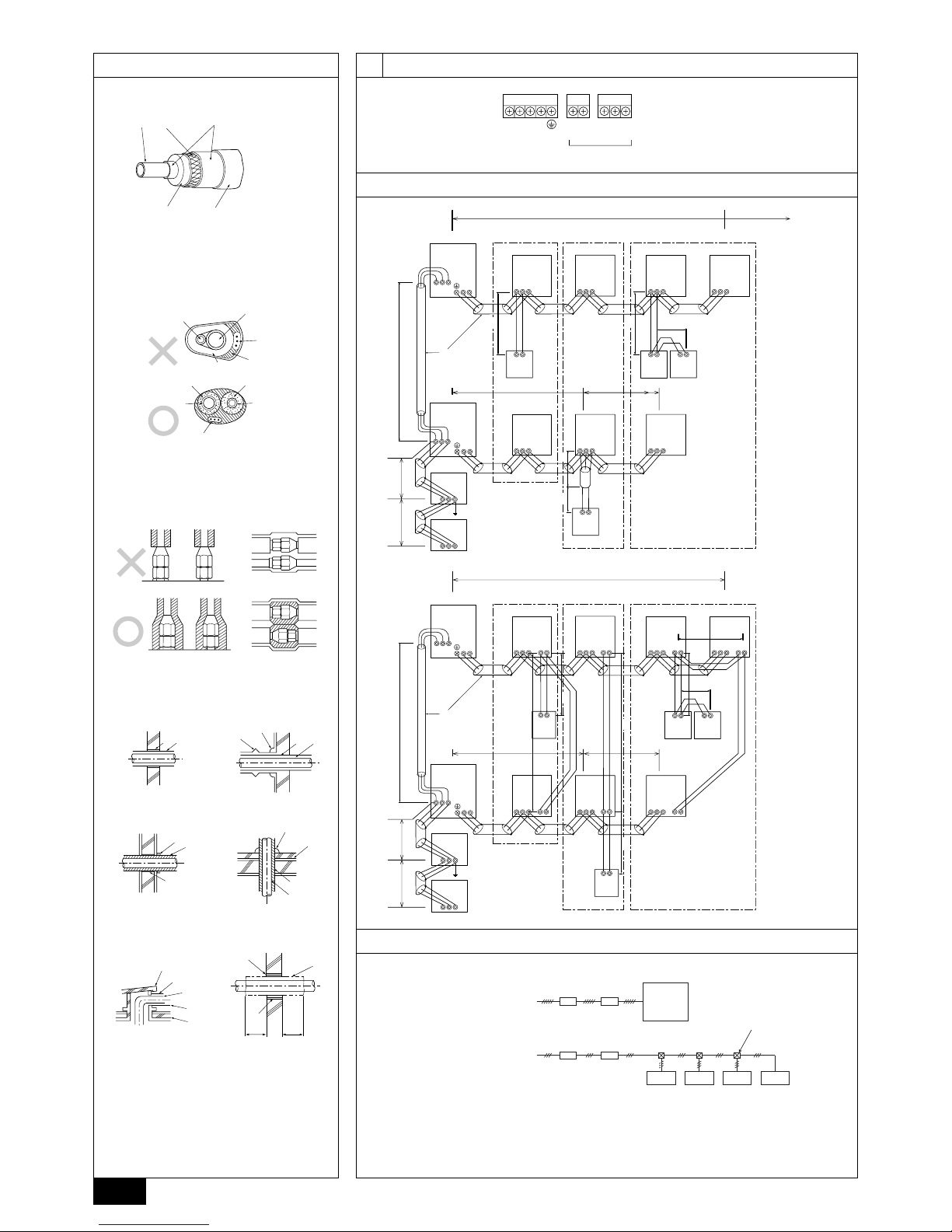
[Fig. 8.4.1] (P.4)
A Steel wire B Piping
C Asphaltic oily mastic or asphalt D Heat insulation material A
E Outer covering B
Glass fiber + Steel wire
Adhesive + Heat - resistant polyethylene foam + Adhesive tape
Indoor Vinyl tape
Floor exposed Water-proof hemp cloth + Bronze asphalt
Outdoor Water-proof hemp cloth + Zinc plate + Oily paint
Note:
• When using polyethylene cover as covering material, asphalt roofing shall
not be required.
• No heat insulation must be provided for electric wires.
[Fig. 8.4.2] (P.4)
A Liquid pipe B Gas pipe C Electric wire
D Finishing tape E Insulater
[Fig. 8.4.3] (P.4)
Heat
insulation
material A
Outer
covering B
12
GB
D
F
INL
E
PGRRUTR
9. Wiring
9.1. Caution
1 Follow ordinance of your governmental organization for technical standard re-
lated to electrical equipment, wiring regulations and guidance of each electric
power company.
2 Wiring for control (hereinafter referred to as transmission line) shall be (5 cm
or more) apart from power source wiring so that it is not influenced by electric
noise from power source wiring. (Do not insert transmission line and power
source wire in the same conduit.)
3 Be sure to provide designated grounding work to outdoor unit.
4 Give some allowance to wiring for electrical part box of indoor and outdoor
units, because the box is sometimes removed at the time of service work.
5 Never connect the main power source to terminal block of transmission line. If
connected, electrical parts will be burnt out.
6 Use 2-core shield cable for transmission line. If transmission lines of different
systems are wired with the same multiplecore cable, the resultant poor transmitting and receiving will cause erroneous operations.
7 Only the transmission line specified should be connected to the terminal block
for outdoor unit transmission.
(Transmission line to be connected with indoor unit : Terminal block TB3 for
transmission line, Other : Terminal block TB7 for centralized control)
Erroneous connection does not allow the system to operate.
8 In the case of connecting with an upper class controller or to conduct group
operation in different refrigerant systems, the control line for transmission is
required between the outdoor units.
Connect this control line between the terminal blocks for centralized control.
(2-wire line with no polarity)
When conducting group operation in different refrigerant systems without connecting to the upper class controller, replace the insertion of the short circuit
connector from CN41 of one outdoor unit to CN40.
9 Group is set by operating the remote controller.
9.2. Control box and connecting position of
wiring
1. Connect the indoor unit transmission line to transmission terminal block (TB3),
or connect the wiring between outdoor units or the wiring with the central control system to the central control terminal block (TB7).
When using shielded wiring, connect shield ground of the indoor unit transmission line to the earth screw (
) and connect shield ground of the line between
Penetrations
[Fig. 8.4.4] (P.4)
<A> Inner wall (concealed) <B> Outer wall
<C> Outer wall (exposed) <D> Floor (waterproofing)
<E> Roof pipe shaft
<F> Penetrating portion on fire limit and boundary wall
2 Wiring examples
• Controller name, symbol and allowable number of controllers.
2. Remote control cables
Kind of remote control cable
Cable diameter
Remarks
2-core cable (unshielded)
0.3 to 1.25 mm
2
When 10 m is exceeded, use cable with the
same specifications as (1) Transmission line
wiring
Name
Outdoor unit controller
Indoor Unit Controller
Remote Controller
Symbol
OC
IC
RC
Allowable number of controllers
One to sixteen controllers for one OC
Maximum of two per group
outdoor units and the central control system transmission line to the shield (S)
terminal of the central control terminal block (TB7) shield (S) terminal. In addition, in the case of outdoor units whose power supply connector CN41 has
been replaced by CN40, the shield terminal (S) of terminal block (TB7) of the
central control system should also be connected to the ground (
).
[Fig. 9.2.1] (P.4)
A Power source B Transmission line
2. Conduit mounting plates (ø27) are being provided. Pass the power supply and
transmission wires through the appropriate knock-out holes, then remove the
knock-out piece from the bottom of the terminal box and connect the wires.
3. Fix power source wiring to terminal box by using buffer bushing for tensile
force (PG connection or the like).
9.3. Wiring transmission cables
1 Types of control cables
1. Wiring transmission cables
• Types of transmission cables: Shielding wire CVVS or CPEVS
• Cable diameter: More than 1.25 mm
2
• Maximum wiring length: Within 200 m
Example of a group operation system with multiple outdoor units (Shielding wires and address setting are
necessary.)
<Examples of Transmission Cable Wiring>
[Fig. 9.3.1] M-NET Remote Controller (P.4)
[Fig. 9.3.2] MA Remote Controller (P.4)
A Group 1 B Group 3 C Group 5 D Shielded Wire E Sub Remote Controller
( ) Address
<Wiring Method and Address Settings>
a. Always use shielded wire when making connections between the outdoor unit (OC) and the indoor unit (IC), as well for all OC-OC, and IC-IC wiring intervals.
b. Use feed wiring to connect terminals M1 and M2 and the ground terminal on the transmission cable terminal block (TB3) of each outdoor unit (OC) to terminals M1, M2
and terminal S on the transmission cable block of the indoor unit (IC).
c. Connect terminals 1 (M1) and 2 (M2) on the transmission cable terminal block of the indoor unit (IC) that has the most recent address within the same group to the
terminal block on the remote controller (RC).
d. Connect together terminals M1, M2 and terminal S on the terminal block for central control (TB7) for the outdoor unit (OC).
e. On one outdoor unit only, change the jumper connector on the control panel from CN41 to CN40.
f. Connect the terminal S on the terminal block for central control (TB7) for the outdoor unit (OC) for the unit into which the jumper connector was inserted into CN40 in Step
above to the ground terminal
in the electrical component box.
g. Set the address setting switch as follows.
To set the outdoor unit address to 100, the outdoor address setting switch must be set to 50.
A Sleeve B Heat insulating material
C Lagging D Caulking material
E Band F Waterproofing laye
G Sleeve with edge H Lagging material
I Mortar or other incombustible caulking
J Incombustible heat insulation material
When filling a gap with mortar, cover the penetration part with steel plate so that
the insulation material will not be caved in. For this part, use incombustible materials for both insulation and covering. (Vinyl covering should not be used.)
13
GB
D
F
INL
E
PGRRUTR
Unit Range Setting Method
IC (Main) 01 to 50 Use the most recent address within the same group of indoor units
IC (Sub) 01 to 50
Use an address, other than that of the IC (Main) from among the units within the same group of indoor units. This must be
in sequence with the IC (Main)
Outdoor Unit 51 to 100 Use the most recent address of all the indoor units plus 50
M-NET R/C (Main) 101 to 150 Set at an IC (Main) address within the same group plus 100
M-NET R/C (Sub) 151 to 200 Set at an IC (Main) address within the same group plus 150
MA R/C – Unnecessary address setting (Necessary main/sub setting)
h. The group setting operations among the multiple indoor units is done by the remote controller (RC) after the electrical power has been turned on.
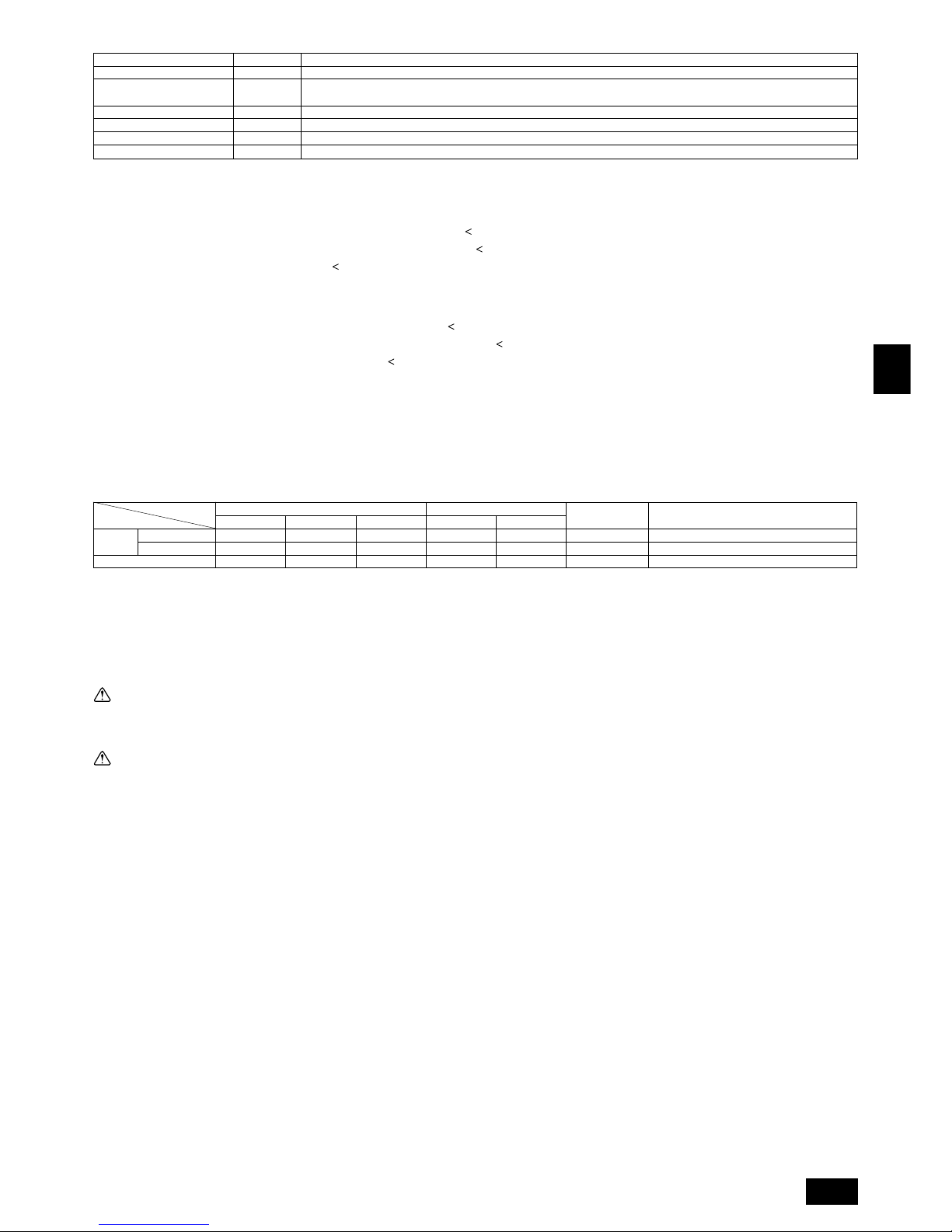
<Permissible Lengths>
1 M-NET Remote controller
• Max length via outdoor units: L1+L2+L3+L4 and L1+L2+L3+L5 and L1+L2+L6+L7 = 500 m (1.25 mm2 or more)
• Max transmission cable length: L
1 and L3+L4 and L3+L5 and L6 and L2+L6 and L7
=
200 m (1.25 mm2 or more)
• Remote controller cable length: r
1, r2, r3, r4
=
10 m (0.3 to 1.25 mm2)
If the length exceeds 10 m, use a 1.25 mm
2
shielded wire. The length of this section (L8) should be included in the calculation of the
maximum length and overall length.
2 MA Remote controller
• Max length via outdoor unit (M-NET cable): L1+L2+L3+L4 and L1+L2+L6+L7 = 500 m (1.25 mm2 or more)
• Max transmission cable length (M-NET cable): L
1 and L3+L4 and L6 and L2+L6 and L7
=
200 m (1.25 mm2 or more)
• Remote controller cable length: c
1+c2 and c1+c2+c3+c4
=
200 m (0.3 to 1.25 mm2)
30 A
30 A
20 A
25
32
16
25
32
16
4.0
4.0
1.5
4.0
4.0
1.5
Indoor Unit
Main Cable
Switch (A)
Minimum Wire Thickness (mm
2
)
Branch Capacity Fuse
Breaker for Current Leakage
Model
Outdoor
Unit
200
250
1. Use a separate power supply for the outdoor unit and indoor unit.
2. Bear in mind ambient conditions (ambient temperature,direct sunlight, rain water,etc.) when proceeding with the wiring and connections.
3. The wire size is the minimum value for metal conduit wiring. The power cord size should be 1 rank thicker consideration of voltage drops.
Make sure the power-supply voltage does not drop more than 10 %.
4. Specific wiring requirements should adhere to the wiring regulations of the region.
5. Power supply cords of parts of appliances for outdoor use shall not be lighter than polychloroprene sheathed flexible cord (design 245 IEC57). For example,
use wiring such as YZW.
6. A switch with at least 3 mm contact separation in each pole shall be provided by the Air conditioner installation.
Warning:
• Be sure to use specified wires to connect so that no external force is imparted to terminal connections. If connections are not fixed firmly, it may cause
heating or fire.
• Be sure to use the appropriate type of overcurrent protection switch. Note that generated overcurrent may include some amount of direct current.
Caution:
• Some installation site may require attachment of an earth leakage breaker. If no earth leakage breaker is installed, it may cause an electric shock.
• Do not use anything other than breaker and fuse with correct capacity. Using fuse and wire or copper wire with too large capacity may cause a malfunction
of unit or fire.
–
–
1.5
Breaker for
Wiring (NFB)Ground
9.4. Wiring of main power supply and equipment capacity
Schematic Drawing of Wiring (Example)
[Fig. 9.4.1] (P.4)
A Switch (Breakers for Wiring and Current Leakage) B Breakers for Current Leakage C Outdoor Unit
D Pull Box E Indoor Unit
Thickness of Wire for Main Power Supply and On/Off Capacities
30 A 100 mA 0.1sec. or less
30 A 100 mA 0.1sec. or less
20 A 30 mA 0.1sec. or less
14
GB
D
F
INL
E
PGRRUTR
10. Test run
10.1. The following phenomena do not represent trouble (emergency)
Display of remote controller
“Cooling (heating)” flashes
Normal display
Normal display
Defrost display
No lighting
Heat ready
Normal display
“HO” flashes
Light out
Cause
When another indoor unit is performing the heating (cooling) operation, the cooling (heating) operation is not performed.
Because of the control operation of auto vane, it may change over to horizontal
blow automatically from the downward blow in cooling in case the downward
blow operation has been continued for 1 hour. At defrosting in heating, hot adjusting and thermostat OFF, it automatically changes over to horizontal blow.
Ultra-low speed operation is commenced at thermostat OFF.
Light air automatically changes over to set value by time or piping temperature at
thermostat ON.
The fan is to stop during defrosting.
Fan is to run for 1 minute after stopping to exhaust residual heat (only in heating).
Ultra low-speed operation for 5 minutes after SW ON or until piping temperature
becomes 35°C, low speed operation for 2 minutes thereafter, and then set notch
is commenced. (Hot adjust control)
When the outdoor unit is being cooled and the refrigerant is resting, warming up
operation is performed for at least 35 minutes to warm the compressor.
During this time, only the fan operates.
System is being driven.
Operate remote controller again after “HO” disappear.
After a stop of cooling operation, unit continues to operate drain pump for three
minutes and then stops it.
Unit continues to operate drain pump if drainage is generated, even during a
stop.
Phenomenon
Indoor unit does not the perform cooling (heating) operation.
The auto vane runs freely.
Fan setting changes during heating.
Fan stops during heating operation.
Fan does not stop while operation has been
stopped.
No setting of fan while start SW has been
turned on.
Outdoor unit does not operate by turning
switch on.
Indoor unit remote controller shows “HO” indicator for about two minutes when turning
ON universal power supply.
Drain pump does not stop while unit has been
stopped.
Drain pump continues to operate while unit
has been stopped.
11. Rating plate
Model
Refrigerant
Allowable pressure (Ps)
Net weight
PUHY-P200 PUHY-P250
13.0 kg
HP: 2.94 MPa, LP: 1.6 MPa
PUHY-P200, P250: 239 kg
MANUFACTURER: MITSUBISHI ELECTRIC CORPORATION
AIR CONDITION & REFRIGERATION SYSTEMS WORKS 6-5-66 TEBIRA, WAKAYAMA CITY, JAPAN
15
GB
D
F
INL
E
PGRRUTR
Inhalt
1. Sicherheitsvorkehrungen
1.1. Vor Installations- und Elektroarbeiten
s Vor dem Einbau der Anlage vergewissern, daß Sie alle Infor-
mationen über “Sicherheitsvorkehrungen” gelesen haben.
s Die “Sicherheitsvorkehrungen” enthalten sehr wichtige
Sicherheitsgesichtspunkte. Sie sollten sie unbedingt befolgen.
Im Text verwendete Symbole
Warnung:
Beschreibt Vorkehrungen, die beachtet werden sollten, um den Benutzer vor
der Gefahr von Verletzungen oder tödlicher Unfälle zu bewahren.
Vorsicht:
Beschreibt Vorkehrungen, die beachtet werden sollten, um die Anlage vor
Schäden zu bewahren.
Innerhalb der Abbildungen verwendete Symbole
: Verweist auf eine Handlung, die unterbleiben muß.
: Verweist auf wichtige Anweisungen, die befolgt werden müssen.
: Verweist auf ein Teil, das geerdet werden muß.
: Gefahr von elektrischem Schlag. (Dieses Symbol findet sich als Aufkleber
auf der Hauptanlage.) <Farbe: gelb>
Warnung:
Die auf der Hauptanlage angebrachten Aufkleber sorgfältig lesen.
Warnung:
• Bitten Sie Ihren Fachhändler oder einen geprüften Fachtechniker, die Installation der Anlage vorzunehmen.
- Unsachgemäße Installation durch den Benutzer kann Wasseraustritt, Strom-
schläge oder Brände verursachen.
• Die Anlage an einem Ort installieren, der genügend Tragkraft für deren
Gewicht besitzt.
- Bei ungenügender Tragkraft kann das Gerät herunterfallen und Verletzun-
gen verursachen.
• Zur Verdrahtung die angegebenen Kabel verwenden. Die Anschlüsse so
sichern, daß Zugspannung von außen nicht auf die Klemmen wirken kann.
- Falscher Anschluß und falsche Befestigung führen zu Wärmebildung und
verursachen Brände.
• Vorsorge gegen heftige Windstöße und Erdbeben treffen, und die Anlage
an dem angegebenen Ort installieren.
- Durch unsachgemäße Installation kann die Anlage herunterfallen und Ver-
letzungen verursachen.
• Stets einen Filter und sonstiges Zubehör gemäß Angaben von Mitsubishi
Electric verwenden.
- Einen geprüften Techniker bitten, die Zusatzeinrichtungen zu installieren.
Unsachgemäße Installation durch den Benutzer kann zu Wasseraustritt,
Stromschlägen oder Bränden führen.
• Die Anlage niemals selbst reparieren. Wenn die Anlage repariert werden
muß, wenden Sie bitte sich an den Fachhändler.
- Wenn die Anlage unsachgemäß repariert wird, kann dies zu Wasseraustritt,
Stromschlägen oder Bränden führen.
• Nicht die Wärmetauscherleitung berühren.
- Unsachgemäße Handhabung kann zu Verletzungen führen.
• Wenn Kältemittelgas während der Installationsarbeiten austritt, den Raum
gründlich lüften.
- Wenn das Kältemittelgas auf offenes Feuer trifft, wird giftiges Gas freige-
setzt.
• Die Anlage gemäß Anweisungen in diesem Installations-handbuch installieren.
- Bei unsachgemäßer Installation kann dies zu Wasseraustritt, Stromschlä-
gen oder Bränden führen.
• Elektroarbeiten durch einen zugelassenen Fachelektriker in Übereinstimmung mit dem “Electric Facility Engineering Standard” - (Technische
Normen für Elektroeinrichtungen), den “Interior Wire Regulations” - (Vorschriften zur Innenverdrahtung) und den in diesem Handbuch gegebenen Anweisungen vornehmen. Anlage auch immer an einen gesonderten Stromkreis anschließen.
- Wenn die Leistung der Stromquelle ungenügend ist oder die Elektroarbeiten
unsachgemäß ausgeführt wurden, kann dies zu Stromschlägen und zu Bränden führen.
• Die Abdeckung der Elektroanschlüsse der Außenanlage (Abdeckplatte)
fest anbringen.
- Wenn die Abdeckung der Elektroanschlüsse (Abdeckplatte) nicht sachge-
mäß angebracht wurde, kann Staub oder Wasser in die Außenanlage eindringen und Brände oder Stromschläge verursachen.
• Beim Verbringen der Anlage an einen anderen Standort, Anlage nicht mit
einem anderen Kältemittel als dem auf der Anlage angegebenen Kältemittel füllen.
- Wenn das ursprüngliche Kältemittel mit einem anderen Kältemittel oder mit
Luft vermischt wird, kann dies zu Fehlfunktionen des Kältemittelkreislaufs
führen und die Anlage beschädigt werden.
• Wenn die Anlage in einem kleinen Raum installiert wird, müssen Maßnahmen ergriffen werden, damit die Kältemittelkonzentration auch bei
Kältemittelaustritt den Sicherheitsgrenzwert nicht überschreitet.
- Befragen Sie einen Fachhändler bezüglich geeigneter Maßnahmen zur Ver-
hinderung des Überschreitens des Grenzwertes. Sollte durch Austreten von
Kältemittel das Überschreiten des Grenzwertes erfolgen, besteht wegen
möglichem Sauerstoffmangel im Raum Gesundheitsgefahr.
• Beim Verbringen der Anlage an einen anderen Ort einen Fachhändler
oder einen geprüften Techniker zur Neuaufstellung hinzuziehen.
- Bei unsachgemäßer Installation der Anlage kann Wasser austreten, und es
können Stromschlage oder Brände verursacht werden.
• Nach Abschluß der Installationsarbeiten sicherstellen, daß kein
Kältemittelgas austritt.
- Wenn Kältemittelgas austritt und mit einem Heizgebläse, einem Ofen oder
sonstigen Wärmequellen in Berührung kommt, kann giftiges Gas erzeugt
werden.
• Die Einstellungen der Schutzvorrichtungen nicht neu einrichten oder
ändern.
- Wenn Druckschalter, Thermoschalter oder eine andere Schutzvorrichtung
kurzgeschlossen oder mit Gewalt betätigt wird oder wenn andere als die von
Mitsubishi Electric angegebenen Teile verwendet werden, besteht Brandoder Explosionsgefahr.
• Zum Entsorgen dieses Gerätes wenden Sie sich an Ihren Fachhändler.
• Der Installateur und der Systemfachmann müssen für die Sicherung gegen Wasseraustritt gemäß den örtlichen Bestimmungen und Normen
sorgen.
- Falls keine örtlichen Bestimmungen bestehen, sind die nachstehenden Nor-
men anzuwenden.
• Besonders darauf achten, einen Aufstellungsort auszuwählen, wie etwa
ein Untergeschoß etc., von dem aus Kältemittelgas nicht in die Atmosphäre entweichen kann, da Kältemittel schwerer als Luft ist.
1. Sicherheitsvorkehrungen .......................................................................... 15
1.1. Vor Installations- und Elektroarbeiten ...................................... 15
1.2. Vorsichtsmaßnahmen für Vorrichtungen, die das Kältemittel
R407C verwenden ................................................................... 16
1.3. Vorsicht in Bezug auf die zum Ersatz bestimmte
Ausrüstung .............................................................................. 16
1.4. Vor Installationsarbeiten .......................................................... 17
1.5. Vor der Installation - Elektroarbeiten ....................................... 17
1.6. Vor Installationsbeginn ............................................................ 18
2. Kombination mit Innenaggregaten ............................................................ 18
3. Überprüfung des Lieferumfangs ............................................................... 18
4. Vorgeschriebener Freiraum um das Aggregat .......................................... 18
5. Hebemethode und Gewicht der Klimaanlage ........................................... 19
6. Einbau der Klimaanlage ............................................................................ 19
6.1. Einbau ..................................................................................... 19
7. Installation der Kältemittelleitungen .......................................................... 19
7.1. Vorsicht .................................................................................... 19
7.2. Das Kältemittel Rohrsystem .................................................... 20
8. Zusätzliches Kühlmittel einfüllen ............................................................... 20
8.1. Kalkulation des zusätzlichen Kühlmittels ................................. 20
8.2. Vorsichtsmaßregeln beim Rohrleitungsanschluß und dem
Betrieb der Armatur ................................................................. 20
8.3. Überprüfung der Dichtheit, Evakuieren und Einfüllen von
Kältemitteln.............................................................................. 21
8.4. Kältedämmung und Kältemittelleitung ..................................... 22
9. Verdrahtung .............................................................................................. 22
9.1. Vorsicht .................................................................................... 22
9.2. Reglerkasten und Kabelanschlußpunkte ................................ 23
9.3. Übertragungskabelanschluß ................................................... 23
9.4. Verdrahtung der Hauptspannungsversorgung und Kapazität
der Einheiten ........................................................................... 24
10. Testbetrieb ................................................................................................ 24
10.1. Die folgenden Symptome sind nicht als Betriebsstörungen
(Notfall) anzusehen ................................................................. 24
11. Typenschild ............................................................................................... 24
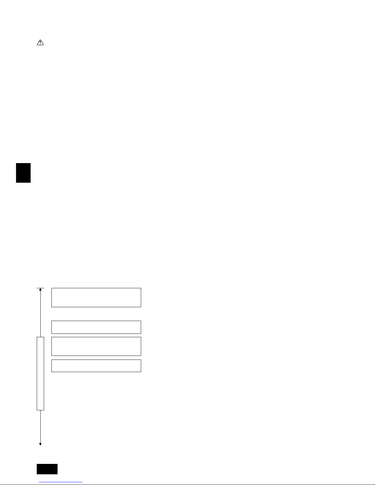
16
GB
D
F
INL
E
PGRRUTR
• Keinen Füllzylinder verwenden.
- Bei Verwendung eines Füllzylinders kann das Kältemittel verderben.
• Beim Einsatz der Handhabungsvorrichtungen besondere Sorgfalt walten lassen.
- Wenn Staub, Schmutz oder Wasser in den Kältemittelkreislauf gelangt, kann
dies zur Qualitätsminderung des Kältemittels führen.
1.3. Vorsicht in Bezug auf die zum Ersatz be-
stimmte Ausrüstung
• Die Armatur nicht vor Ausführung der Mineralölwiederaufbereitung betätigen.
- Betätigen der Armatur vor Durchführung der Mineralölwiederaufbereitung
kann eine Qualitätsverschlechterung bei der Mineralölwiederaufbereitung zur
Folge haben.
• Zur Mineralölwiederaufbereitung kann es manchmal erforderlich sein, die
Steuerung der Anlage und die MA-Fernbedienung abzunehmen.
- Unsachgemäße Handhabung kann dazu führen, daß die
Ölwiederaufbereitung nicht mehr möglich ist.
- Zum Abnehmen, die auf dem PC für die Mineralölwiederaufbereitung ange-
zeigten Anweisungen befolgen.
- Nach Beendigung der Ölwiederaufbereitung die Steuerungen wieder anbrin-
gen.
• Einen sicheren Abstand vom Ventilator des Innengerätes, der während
der Mineralölwiederaufbereitung läuft, einhalten.
- Arbeiten in der Umgebung des Ventilators des Innengerätes können Verlet-
zungen zur Folge haben.
• Die Menge des nachgefüllten Kältemittels aufzeichnen.
(In die Spalte für die Menge des wiederaufgefüllten Kältemittels auf dem
Aufkleber des Innengerätes eintragen.)
- Eine Unterlassung der Beschreibung kann eine Verschlechterung der Quali-
tät der Mineralölwiederaufbereitung zur Folge haben.
- Es kann ebenfalls eine Fehlfunktion oder schlechte Kühl-/Heizleistung zur
Folge haben.
• Während der Mineralölwiederaufbereitung kann auf der Fernbedienung
oder der Steuerung der Anlage eine Fehlermeldung angezeigt werden.
- Wenn während der Mineralölwiederaufbereitung eine Fehlermeldung ange-
zeigt wurde, die Fehlermeldung nach Abschluß der Aufbereitung wieder zurücksetzen.
• Zur Ausführung der Kältemittelwiederaufbereitung/Evakuierung der Innenseite einer vorhandenen Rohrleitung nur solche Werkzeuge, z.B. Füllschläuche, auswählen, die für R407C verwendet wurden.
- Die Verwendung eines Füllschlauchs für R407C führt dazu, daß es sich mit
konventionellem Kältemittelmaschinenöl vermischt, was eine Verschlechterung des Kältemittelmaschinenöls zur Folge hat.
1.2. Vorsichtsmaßnahmen für Vorrichtungen,
die das Kältemittel R407C verwenden
Vorsicht:
• Für die Kältemittelrohrleitung nahtlose Rohre und Röhren aus Phosphor-
desoxidiertem Kupfer und entsprechenden Kupferlegierungen verwenden. Außerdem vergewissern, daß die Innen- und Außenflächen der Rohrleitungen sauber und frei von gefährlichem Kupfer, Oxyden, Staub/
Schmutz, Metallbearbeitungsrückständen, Ölen, Feuchtigkeit oder anderen Verunreinigungen sind.
- Verunreinigungen auf der Innenseite der Kältemittelrohrleitungen können dazu
führen, daß das Kältemittelrestöl verdirbt.
• Die bei der Installation verwendete Rohrleitung in einem geschlossenen
Raum aufbewahren und beide Enden bis unmittelbar vor dem Hartlöten
geschlossen halten. (Krümmer und andere Rohrverbinder in einem
Kunststoffbeutel aufbewahren).
- Wenn Staub, Schmutz oder Wasser in den Kältemittelkreislauf gelangt, kann
dies zu einer Qualitätsminderung des Öls und zu Kompressorstörungen führen.
• Zum Beschichten der Konus- und Flanschanschlüsse Esteröl/Ätheröl oder
Alkylbenzol (kleine Menge) als Kältemaschinenöl verwenden.
- Das Kältemaschinenöl zersetzt sich, wenn es mit größeren Mengen Mine-
ralöl vermischt wird.
• Zur Füllung des Systems flüssiges Kältemittel verwenden.
- Wenn Kältemittelgas zur Füllung des Systems verwendet wird, ändert sich
die Zusammensetzung des Kältemittels im Zylinder, so daß die Leistung
abfallen kann.
• Kein anderes Kältemittel als R407C verwenden.
- Wenn ein anderes Kältemittel (R22 usw.) mit R407C gemischt wird, kann
das im Kältemittel enthaltene Chlor Verschlechterung des Kältemaschinenöls verursachen.
• Eine Vakuumpumpe mit einem Reverse Flow (Gegenstrom)- Rückschlagventil verwenden.
- Das Öl der Vakuumpumpe fließt in den Kältemittelkreislauf zurück und führt
zur Qualitätsminderung des Kältemaschinenöls.
• Folgende Vorrichtungen, die bei herkömmlichen Kältemitteln verwendet
werden, nicht einsetzen.
(Meßrohrleitung, Füllschlauch, Gasaustrittsdetektor, Reverse Flow (Gegenstrom)- Rückschlagventil, Kältemittelfüllständer, Kältemittelaufbereitungseinrichtungen)
- Wenn ein herkömmliches Kältemittel und Kältemaschinenöl mit R407C vermischt
werden, kann dies zur Qualitätsminderung des Kältemaschinenöls führen.
- Wenn R407C mit Wasser vermischt wird, kann dies zur Qualitätsminderung
des Kältemaschinenöls führen.
- Da R407C kein Chlor enthält, reagieren Gasaustrittssuchgeräte für herkömm-
liche Kältemittel nicht darauf.
Zu beachtende Gesichtspunkte
• Bitte beachten Sie, daß unser Unternehmen für die Zuverlässigkeit bei der Wiederverwendung
der bestehenden Rohrleitung, Elektroleitung und Netzanschlusses (in Bezug auf die Gasdichtigkeit
der Rohrleitung, Fehlerhaftigkeit/Anschlußmängel von Teilen der Elektroleitung, abgenutzte Isolierung sowie typische Fehler aufgrund des Verschleißes der Anlage) nicht haftbar ist.
• Für die Grenzwerte der Kältemittelrohrleitung und die anzuwendenden Rohrdurchmesser überprüfen Sie bitte die für die Wiederverwendung vorgesehenen bestehenden Rohrleitungen gemäß den Angaben in der Prüfliste unter Beachtung der Warenkataloge und Handbücher zur
Beurteilung der Eignung für die Wiederverwendung.
• Wenn in der Vergangenheit Dampfniederschlagsbildung festgestellt wurde, überprüfen Sie bitte
die Wärmeisolierung.
• Bereiche, die herabtropfendes Kondenswasser aufweisen, auf abgenutzte Isolierung überprüfen und bei Bedarf das Isoliermaterial ersetzen.
• Wenn die Kupferrohrleitung schwerwiegende Abnutzungserscheinungen aufweist, die Bereiche
mit Grünspan oder schwarzen Flecken nicht wiederverwenden.
• Für die Wiederverwendung von vorhandenen Steuerleitungen zwischen Außengerät und Fernbedienung die Leitung selbst, Art und Größe u.ä. auf der Grundlage der Prüfliste zur Beurteilung
der Einsatzmöglichkeit überprüfen.
• Selbst wenn das Obengesagte nicht dem entsprechenden Punkt auf der Prüfliste entspricht,
kann die bestehende Leitung je nach Anzahl der anzuschließenden Innengeräte und der Rohrlänge wiederverwendet werden. Wegen Einzelheiten wenden Sie sich bitte an uns.
• Beim Netzanschluß Spannung und Anzahl der Phasen entsprechend dem Außengerät, dem
Innengerät und dem Wärmespeicher berücksichtigen und die Leistung des Unterbrechers sowie
die Leitungsgröße gemäß Schaltplan für die Netzanschlußleitung anpassen.
• Wenn der bestehende Netzanschluß (einschließlich Netzanschlußleitung) verwendet wird, das
System auf Verschleiß und Schäden überprüfen.
• Das in der bestehenden Anlage benutzte Kältemittelmaschinenöl prüfen. (Wenn bei der Überprüfung des Öls festgestellt wird, daß das in der bestehenden Anlage verwendete Kältemittelmaschinenöl Mineralöl ist, zur Inspektion die Mustersammlung für Esteröle verwenden).
Vorsicht bei Installationsarbeiten für REPLACE MULTI (Ersatz von Mehrfachgeräten).
Ablauf von Installationsarbeiten im Arbeitsgebiet
Vergewissern über die Möglichkeit der Wiederverwendung eines bestehenden
Netzanschlußsystems.
Vergewissern über den objektiven Bereich der
Ersatzarbeiten.
Vergewissern über die Möglichkeit der Wiederverwendung einer bestehenden Steuerleitung
Vergewissern über die Möglichkeit der Wiederverwendung einer bestehenden Kältemittelrohrleitung.
Vor Installationsarbeiten vor Ort
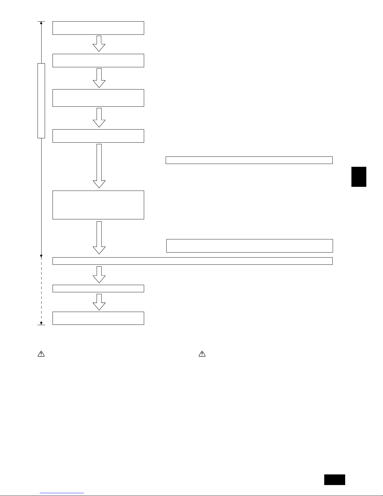
17
GB
D
F
INL
E
PGRRUTR
1.4. Vor Installationsarbeiten
Vorsicht:
• Anlage nicht an Orten installieren, wo brennbares Gas austreten kann.
- Wenn Gas austritt und sich um die Anlage herum ansammelt, kann dies zu
einer Explosion führen.
• Anlage nicht an Orten verwenden, wo sich Lebensmittel, Tiere, Pflanzen,
Präzisionswerkzeuge oder Kunstgegenstände befinden.
- Die Qualität der Lebensmittel etc. kann sich verschlechtern.
• Anlage nicht unter besonderen Umfeldbedingungen einsetzen.
- Dichter Öldampf, Dampf oder schwefelhaltiger Rauch können die Leistung
der Klimageräte erheblich beeinträchtigen oder Teile der Anlage beschädigen.
• Bei Installation der Anlage in einem Krankenhaus, einer Rundfunkstation oder an ähnlichen Orten für ausreichend Lärmschutz sorgen.
- Der Betrieb der Anlage kann gestört oder unterbrochen werden, wenn sie
durch Aufnahmegeräte, private Stromerzeugungseinrichtungen, medizinische
Hochfrequenzgeräte oder Rundfunkeinrichtungen beeinflußt wird, und umgekehrt kann der Betrieb der Anlage die Funktion dieser Geräte und Einrichtungen beeinträchtigen und Lärm erzeugen, der ärztliche Behandlungen stört
oder Bildübertragungen beeinträchtigt.
• Die Anlage nicht auf Baueinrichtungen installieren, die Wasseraustritt
verursachen können.
- Wenn die Luftfeuchtigkeit 80 % übersteigt oder wenn die Abwasserleitung
verstopft ist, kann Kondenswasser aus der Innenanlage tropfen. Daher die
vorgesehene Sammelabwasserleitung der Außenanlage einrichten.
Es ist notwendig, Kältemittel in einer Sollwertmenge einzufüllen und die Menge anzupassen. Darauf
achten, dies vorzunehmen, wenn die Rohrlänge nicht bekannt ist
Einzelheiten erfahren Sie bei Ihrem Fachhändler.
■ Die Armatur für die Feldrohrleitung (Rohrleitungsverlängerung) montieren. (Das Kugelventil ist
am Außengerät angebracht).
■ Zur Überprüfung der bestehenden Rohrleitung auf Abnutzung oder Undichtigkeit einen Luftdichtigkeitstest durchführen.
■ Die für die Rohrverlängerung benötigte Menge berechnen und das zusätzliche Kältemittel einfüllen.
Dafür sorgen, der wert in die Spalte für das zusätzlichen Kältemittel auf der Aufschrift des kombinierten Außengerätes, das auf dem Außengerät angebracht ist, einzutragen.
Durchführung der Rohrverlegung (Montage
des Kugelventils)
Luftabdichtung und Evakuierung der bestehenden Rohrleitung und Einfüllen des Kältemittels.
Ausführung der Mineralölwiederaufbereitung
Durchführung des Testlaufs und Vornahme der
Einstellungen (zur Endabnahme des Betriebs).
Vor der Mineralölwiederaufbereitung die Kugelventile des Außengerätes ohne Ausführung eines Arbeitsganges geschlossen halten.
Ausfüllen der geforderten Positionen im Fragebogen der Mineralölwiederaufbereitungsarbeiten des REPLACE MULTI (Ersatz von Mehrfachgeräten).
Wiederaufbereitung des Kältemittels des alten Systems.
Entfernen der Außen-/Innengeräte, der Fernbedienungen etc.
Während Installationsarbeiten vor Ort
Installieren der Außen-/Innengeräte, der Fernbedienungen etc. und Durchführung der
Elektroarbeiten.
Zum Abschluß der Mineralölwiederaufbereitung nicht den Kompressor laufen lassen.
Einstellung der Adressenüberprüfung der Anlage.
■ Außengerät
• Den Freiraum um das Außengerät herum sicherstellen.
(Den Installationsfreiraum für den Ölauffangbehälter ermitteln)
■ Die Netzspannung einschalten und sich über die normale Arbeitsweise der Anlage vergewissern.
• Die Fernbedienung oder das Außengerät auf Fehleranzeigen überprüfen.
• Nach Einschalten der Fernbedienung das Innengerät für den Gebläsebetrieb laufen lassen
und die Luftzufuhr und die Luftstromrichtung überprüfen.
• Wenn die für die Wiederverwendung benötigte Rohrleitungslänge unbekannt ist, muß auf der
Grundlage der Menge des wiederaufbereiteten Kältemittels eine zusätzliche Kältemittelfüllung
berechnet werden. Aus diesem Grunde bitten wir Sie höflich, das gesamte Kältemittel in den
bestehenden Außen-/Innengeräten und der verlängerten Rohrleitung wieder aufzubereiten, und
die Menge zu überprüfen und aufzuzeichnen. (Die Standardmenge des zusätzlichen Kältemittels beträgt (Menge des wiederaufbereiteten R22 – eingefüllte Menge des bestehenden Außengerätes) + 3 kg). Die Kältemittelmenge nach Wiederaufbereitung des Mineralöls anpassen.)
1.5. Vor der Installation - Elektroarbeiten
Vorsicht:
• Erdung der Anlage.
- Die Erdungsleitung nicht an Gas- oder Wasserrohre, Beleuchtungsstäbe oder
an die Erdleitungen von Telefonen anschließen. Unsachgemäße Erdung kann
zu Stromschlägen führen.
• Die Gegenphase von L-Leitungen (L
1, L2, L3) kann festgestellt werden
(Fehlerkabel: 4103), aber die Gegenphase von L-Leitungen und N-Leitung kann nicht festgestellt werden.
- Wenn bei fehlerhafter Verdrahtung Strom zugeführt wird, können einige
Elektroteile beschädigt werden.
• Netzstromleitungen so anbringen, daß keine Zugspannung auf die Kabel
ausgeübt wird.
- Zugspannung kann Kabelbruch, Wärmebildung und Brände verursachen.
• Einen Fehlerstromschutzschalter wie vorgesehen anbringen.
- Wenn kein Fehlerstromschutzschalter angebracht wird, können Stromschlä-
ge verursacht werden.
• Netzstromkabel mit ausreichender Stromstärke und Nennwertauslegung
verwenden.
- Zu kleine Kabel können Fehlstrom verursachen, Wärme erzeugen und Brand
ausbrechen lassen.
• Nur Stromunterbrecher und Sicherungen der angegebenen Leistung verwenden.
- Eine Sicherung oder ein Stromunterbrecher von größerer Stärke oder Stahl-
 Loading...