

Page 1

Air-Conditioners For Building Application
OUTDOOR UNIT
PUHY-P-YMF-C PUY-P-YMF-C
PUHY-YMF-C PUY-YMF-C
GB
D
F
INSTALLATION MANUAL
For safe and correct use, please read this installation manual thoroughly before installing the air-conditioner unit.
INSTALLATIONSHANDBUCH
Zum sicheren und ordnungsgemäßen Gebrauch der Klimageräte das Installationshandbuch gründlich durchlesen.
MANUEL D’INSTALLATION
Veuillez lire le manuel d’installation en entier avant d’installer ce climatiseur pour éviter tout accident et vous assurer d’une utilisation correcte.
MANUAL DE INSTALACIÓN
Para un uso seguro y correcto, lea detalladamente este manual de instalación antes de montar la unidad de aire acondicionado.
MANUALE DI INSTALLAZIONE
Per un uso sicuro e corretto, leggere attentamente questo manuale di installazione prima di installare il condizionatore d’aria.
INSTALLATIEHANDLEIDING
Voor een veilig en juist gebruik moet u deze installatiehandleiding grondig doorlezen voordat u de airconditioner installeert.
MANUAL DE INSTALAÇÃO
Para segurança e utilização correctas, leia atentamente este manual de instalação antes de instalar a unidade de ar condicionado.
E°XEIPI¢IO O¢H°IøN E°KATA™TA™H™
°И· ·ЫК¿ПВИ· О·И ЫˆЫЩ‹ ¯Ъ‹ЫЛ, ·Ъ·О·ПВ›ЫЩВ ‰И·‚¿ЫВЩВ ЪФЫВ¯ЩИО¿ ·˘Щfi ЩФ ВБ¯ВИЪ›‰ИФ ВБО·Щ¿ЫЩ·ЫЛ˜ ЪИУ ·Ъ¯›ЫВЩВ ЩЛУ
ВБО·Щ¿ЫЩ·ЫЛ ЩЛ˜ МФУ¿‰·˜ ОПИМ·ЩИЫМФ‡.
РУКОВОДСТВО ПО УСТАНОВКЕ
Для осторожного и правильного использования прибора необходимо тщательно ознакомиться с данным руководством по
установке до выполнения установки кондиционера.
E
I
NL
P
GR
RU
TR
MONTAJ ELK‹TABI
Emniyetli ve do¤ru biçimde nas›l kullan›laca¤›n› ö¤renmek için lütfen klima cihaz›n› monte etmeden önce bu elkitab›n› dikkatle okuyunuz.
Page 2
4
AAFA
[Fig. 4.0.1]
(1)
(3)
<A>
>
L2
=
>
L1
=
A
<A> : Top view
<B> : Side view
<C> : When there is little space up to an
obstruction
A : Front
B : No restrictions on wall height
(left and right)
C : Air outlet guide (Procured at the site)
<B>(2)
>
45°
=
>
1000
>
300
=
=
(5)
>
L2
E
=
DD
AA
>
>
1000
=
E
AAAAA
>
L
1
=
D
>
>
L
1
=
>
L
1
=
=
E
E
>
L
1
L
1
=
L1
=
E
>
L
2
=
>
L
2
=
<C>
<A>
C
<B>
>
L
1
=
>
L
2
=
DD
>
1000
=
E
AA
E
>
900
=
>
L
2
=
>
2
L
=
>
L
2
=
A
A
>
L
1
=
B
(4)
<A>
>
=
L
2
<B>
>
L
1
=
>
L
2
=
A
>
L
1
=
650
Hh
h
325
H
A
5 6
[Fig. 5.0.1]
<
40°
=
>
7 m
=
Hh
[Fig. 6.1.1]
B
A
A : M10 anchor bolt procured
at the site.
B : Corner is not seated.
>
1000
=
[Fig. 6.1.2]
26
80
38
A
6.1
160
D
>
1000
A
900
=
A
D
>
=
D : Must be open
E : Wall height (H)
F : No restrictions on wall height
L1 L2
PU(H)Y-YMF 450 250
PU(H)Y-P-YMF 450 450
15
5555
29
57
560
B
760
C
990
840 880
A : Bottom piping through hole
B : (bolt hole)
C : (bolt hole for old models)
910
6.2
>
7 m
=
[Fig. 6.2.1]
>
100
=
2
Page 3
7
L
M
1
3
7.2
8
8.2
[Fig. 7.2.1]
A
B C D
a b c d
B
C
CCC
e
C
A
B
b
a
c d
CC
D
e
CCC
C
A (mm)
Å Liquid pipe ı Gas pipe
PU(H)Y-(P)200 ø12.7 ø25.4
PU(H)Y-(P)250 ø12.7 ø28.58
B, C, D (mm)
Ç Total capacity of indoor units Å Liquid pipe ı Gas pipe
~ 80 ø9.52 ø15.88
81 ~ 160 ø12.7 ø19.05
161 ~ ø12.7 ø25.4
a, b, c, d, e (mm)
Î Model number Å Liquid pipe ı Gas pipe
20,25,32,40 ø6.35 ø12.7
50,63,80 ø9.52 ø15.88
100,125,140 ø9.52 ø19.05
200 ø12.7 ø25.4
250 ø12.7 ø28.58
‰ Downstream Unit Model Total Ï Branch Kit Model
~ 160 CMY-Y102S-F
161 ~ CMY-Y102L-F
Ì 4-Branching Header Ó 7-Branching Header È 10-Branching Header
CMY-Y104-E CMY-Y107-E CMY-Y1010-E
A : Outdoor Unit
B : First Branch
C : Indoor unit
D : Cap
[Fig. 8.2.1]
[Fig. 8.2.2]
A
B
C
D
[Fig. 8.2.3]
<A> [Ball valve (gas side)]
(This figure shows the valve
in the fully open state.)
EE
S
O
J
<B> [Ball valve (liquid side)]
S
O
I
A : Valve stem
B : Stopper pin
K
C : Packing (Accessory)
D : Connecting pipe (Accessory)
E : Open (Operate slowly)
F : Cap, copper packing
G : Service port
H : Flare nut
I : ø12.7
J : ø25.4 (PU(H)Y-(P)200)
ø28.58 (PU(H)Y-(P)250)
K : Field piping
L : Close-packed packing
M : Hollow packing
F
G
H
[Fig. 8.3.1]
A
C
[Fig. 8.3.3]
8.3
[Fig. 8.3.2]
LO HI
B
A
G
H
I
J
A : Nitrogen gas
B : To indoor unit
C : System analyzer
D : Lo Knob
E : Hi Knob
F : Stop valve
G : Liquid pipe
H : Gas pipe
I : Outdoor unit
J : Service port
F
B
C
LO
D
HI
E
D
E
F
C
G
H
I
J
M
K
L
A : System analyzer
B : Lo Knob
C : Hi Knob
D : Ball valve
E : Liquid pipe
F : Gas pipe
G : Service port
H : Three-way joint
I : Valve
J : Valve
K : Cylinder
L : Scale
M : Vacuum pump
3
Page 4
8.4
C
A
B
D
E
D D
C
A
D D
A
B
3 N~380 - 450 V
~220 - 240 V
B
A
D
C
E
A B C
E
D
M1 M2
M1 M2 S
TB7
TB3
IC
(51)
M1 M2 S
TB5
RC
(01)
IC
M1 M2 S
TB5
(02)
IC
M1 M2 S
TB5
(04)
IC
M1 M2 S
TB5
(03)
IC
M1 M2 S
TB5
(05)
IC
M1 M2 S
TB5
(07)
IC
M1 M2 S
TB5
(06)
L
2
L
1
(101)
RC
(105)
RC
(103)
RC
(155)
OC
M1 M2
M1 M2 S
TB7
TB3
(52)
OC
r
3
M1M2S
Power Supply
Unit
M1M2S
MJ103
L
3
L
6
L
7
L
4
L
5
r
2
r
4
r
1
AB AB AB
AB
A B C
E
D
M1 M2
M1 M2 S
TB7
TB3
IC
(51)
M1 M2 12S
TB5 TB15
12
TB15
12
TB15
12
TB15
12
TB15
12
TB15
MA
(01)
IC
M1 M2 S
TB5
(02)
IC
M1 M2 S
TB5
(04)
IC
M1 M2 S
TB5
(03)
IC
M1 M2 S
TB5
(05)
IC
M1 M2 S
TB5
(07)
IC
M1 M2 S
TB5
(06)
L
2
L
1
MAMAMA
OC
M1 M2
M1 M2 S
TB7
TB3
(52)
OC
c
1
c
4
c
3
S
Power Supply
Unit
S
MJ103
L
3
L
6
L
7
L
4
c
2
ABABAB
AB
M1M2
M1M2
c
2
c
1
c
1
c
2
[Fig. 8.4.1]
A : Steel wire B : Piping
C : Asphaltic oily mastic or asphalt
D : Heat insulation material A
E : Outer covering B
[Fig. 8.4.2]
9
[Fig. 9.2.1]
[Fig. 9.3.1]
9.2
L1 L2L3 N M1M2 M1M2 S
TB1
TB3 TB7
AB
9.3
A : Power source
B : Transmission line
E
B
E
A
D
A : Liquid pipe B : Gas pipe
C : Electric wire D : Finishing tape
E : Insulater
[Fig. 8.4.3]
[Fig. 8.4.4]
<A> Inner wall (concealed)
A B
<B> Outer wall
D
C
[Fig. 9.3.2]
A B
<C> Outer wall (exposed)
E
B
I
<E> Roof pipe shaft
A : Sleeve B : Heat insulating material
C : Lagging D : Caulking material
E : Band F : Waterproofing laye
G : Sleeve with edge H : Lagging material
I : Mortar or other incombustible caulking
J : Incombustible heat insulation material
4
G
D
B
H
F
<D> Floor (fireproofing)
<F> Penetrating portion on fire
limit and boundary wall
I
A
D
F
A : Group 1
B : Group 3
C : Group 5
G
B
[Fig. 9.4.1]
9.4
A : Switch (Breakers for Wiring and Current Leakage)
B : Outdoor Unit C : Pull Box
D : Indoor Unit
J
1m1m
D : Shielded Wire
E : Sub Remote
Controller
Page 5
Contents
1. Safety precautions ...................................................................................... 5
1.1. Before installation and electric work .......................................... 5
1.2. Precautions for devices that use R407C refrigerant.................. 5
1.3. Before getting installed .............................................................. 6
1.4. Before getting installed (moved) - electrical work...................... 6
1.5. Before starting the test run ........................................................ 6
2. Specifications .............................................................................................. 6
3. Confirmation of parts attached ................................................................... 6
4. Space required around unit ........................................................................ 7
5. Lifting method and weight of product .......................................................... 7
6. Installation of unit ........................................................................................ 7
6.1. Installation ................................................................................. 7
6.2. Connecting direction for refrigerant piping ................................ 7
7. Refrigerant piping installation ..................................................................... 7
7.1. Caution ...................................................................................... 7
1. Safety precautions
1.1. Before installation and electric work
s Before installing the unit, make sure you read all the “Safety
precautions”.
s The “Safety precautions” provide very important points re-
garding safety. Make sure you follow them.
Symbols used in the text
Warning:
Describes precautions that should be observed to prevent danger of injury
or death to the user.
Caution:
Describes precautions that should be observed to prevent damage to the
unit.
Symbols used in the illustrations
: Indicates an action that must be avoided.
: Indicates that important instructions must be followed.
: Indicates a part which must be grounded.
: Beware of electric shock. (This symbol is display ed on the main unit label.)
<Color: yellow>
Warning:
Carefully read the labels affixed to the main unit.
Warning:
• Ask the dealer or an authorized technician to install the air conditioner.
- Improper installation by the user may result in water leakage, electric shock,
or fire.
• Install the unit at a place that can withstand its weight.
- Inadequate strength may cause the unit to fall down, resulting in injuries.
• Use the specified cables for wiring. Make the connections securely so
that the outside force of the cable is not applied to the terminals.
- Inadequate connection and fastening may generate heat and cause a fire.
• Prepare for str ong winds and earthquakes and install the unit at the specified place.
- Improper installation may cause the unit to topple and result in injury.
• Alwa ys use an filter and other accessories specified by Mitsubishi Electric.
- Ask an authorized technician to install the accessories. Improper installation
by the user may result in water leakage, electric shock, or fire.
• Never repair the unit. If the air conditioner must be repaired, consult the
dealer.
- If the unit is repaired improperly, water leakage, electric shock, or fire may
result.
• Do not touch the heat exchanger fins.
- Improper handling may result in injury.
• If refrigerant gas leaks during installation work, ventilate the room.
- If the refrigerant gas comes into contact with a flame, poisonous gases will
be released.
• Install the air conditioner according to this Installation Manual.
- If the unit is installed improperly, water leakage, electric shock, or fire may
result.
7.2. Refrigerant piping system.......................................................... 8
8. Additional Refrigerant Charge .................................................................... 8
8.1. Calculation of Additional Refrigerant Charge ............................ 8
8.2. Caution for piping connection/valve operation........................... 8
8.3. Airtight test, evacuation, and refrigerant charging ..................... 9
8.4. Thermal insulation of refrigerant piping ................................... 10
9. Wiring ........................................................................................................ 10
9.1. Caution .................................................................................... 10
9.2. Control box and connecting position of wiring ......................... 10
9.3. Wiring transmission cables...................................................... 10
9.4. Wiring of main power supply and equipment capacity ............ 11
10. Test run ..................................................................................................... 12
10.1. The following phenomena do not represent trouble
(emergency) ............................................................................ 12
• Have all electric work done by a licensed electrician according to “Electric Facility Engineering Standard” and “Interior Wire Regulations”and
the instructions given in this manual and always use a special circuit.
- If the power source capacity is inadequate or electric work is performed im-
properly, electric shock and fire may result.
• Securely install the outdoor unit terminal cover (panel).
- If the terminal cover (panel) is not installed properly, dust or w ater ma y enter
the outdoor unit and fire or electric shock may result.
• When installing and moving the air conditioner to another site, do not
charge the it with a refrigerant different from the refrigerant (R407C or
R22) specified on the unit.
- If a different refrigerant or air is mixed with the original refrigerant, the refrig-
erant cycle may malfunction and the unit may be damaged.
• If the air conditioner is installed in a small room, measures must be taken
to prevent the refrigerant concentration from exceeding the safety limit
even if the refrigerant should leak.
- Consult the dealer regarding the appropriate measures to prevent the safety
limit from being exceeded. Should the refrigerant leak and cause the safety
limit to be exceeded, hazards due to lack of oxygen in the room could result.
• When moving and reinstalling the air conditioner, consult the dealer or
an authorized technician.
- If the air conditioner is installed improperly, water leakage, electric shoc k, or
fire may result.
• After completing installation work, make sure that refrigerant gas is not
leaking.
- If the refrigerant gas leaks and is exposed to a fan heater, stove, oven, or
other heat source, it may generate noxious gases.
• Do not reconstruct or change the settings of the protection devices.
- If the pressure switch, thermal switch, or other protection device is shorted
and operated forcibly, or parts other than those specified by Mitsubishi Electric are used, fire or explosion may result.
• To dispose of this product, consult your dealer.
• The installer and system specialist shall secure safety against leakage
according to local regulation or standards.
- Following standards may be applicable if local regulation are not available.
• Pay a special attention to the place, such as a basement, etc. where refrigeration gas can stay, since refrigeration is heavier than the air.
1.2. Precautions for devices that use R407C
refrigerant
Caution:
• Do not use the existing refrigerant piping.
- The old refrigerant and refrigerator oil in the existing piping contains a large
amount of chlorine which may cause the refrigerator oil of the new unit to
deteriorate.
• Use refrigerant piping made of phosphorus deo xidized copper and copper alloy seamless pipes and tubes. In addition, be sure that the inner
and outer surfaces of the pipes are clean and free of hazardous sulphur ,
oxides, dust/dirt, shaving particles, oils, moisture, or any other contaminant.
- Contaminants on the inside of the refrigerant piping may cause the refriger-
ant residual oil to deteriorate.
• Store the piping to be used during installation indoors and keep both
ends of the piping sealed until just before brazing. (Store elbows and
other joints in a plastic bag.)
- If dust, dirt, or water enters the refrigerant cycle, deterioration of the oil and
compressor trouble may result.
• Use ester oil, ether oil or alkylbenz ene (small amount) as the refrigerator
oil to coat flares and flange connections.
- The refrigerator oil will degrade if it is mixed with a large amount of mineral
oil.
GB
D
F
E
INL
PGRRUTR
5
Page 6
• Use liquid refrigerant to fill the system.
- If gas refrigerant is used to seal the system, the composition of the refrigerant in the cylinder will change and performance may drop.
• Do not use a refrigerant other than R407C.
- If another refrigerant (R22, etc.) is used, the chlorine in the refrigerant may
cause the refrigerator oil to deteriorate.
• Use a vacuum pump with a reverse flow check valve.
- The vacuum pump oil may flow back into the refrigerant cycle and cause the
refrigerator oil to deteriorate.
• Do not use the following tools that are used with conventional refrigerants.
(Gauge manifold, charge hose, gas leak detector , reverse flow chec k valve,
refrigerant charge base, refrigerant recovery equipment)
- If the conventional refrigerant and refrigerator oil are mixed in the R407C,
the refrigerant may deteriorated.
- If water is mixed in the R407C, the refrigerator oil may deteriorate.
- Since R407C does not contain any chlorine, gas leak detectors for conven-
tional refrigerants will not react to it.
• Do not use a charging cylinder.
- Using a charging cylinder may cause the refrigerant to deteriorate.
• Be especially careful when managing the tools.
- If dust, dirt, or water gets in the refrigerant cycle, the refrigerant may deterio-
rate.
1.3. Before getting installed
GB
Caution:
• Do not install the unit where combustible gas may leak.
- If the gas leaks and accumulates around the unit, an explosion may result.
• Do not use the air conditioner where food, pets, plants, precision instru-
D
ments, or artwork are kept.
- The quality of the food, etc. may deteriorate.
• Do not use the air conditioner in special environments.
- Oil, steam, sulfuric smoke, etc. can significantly reduce the performance of
F
E
INL
the air conditioner or damage its parts.
• When installing the unit in a hospital, communication station, or similar
place, provide sufficient protection against noise.
- The inverter equipment, private power generator, high-frequency medical
equipment, or radio communication equipment may cause the air conditioner
to operate erroneously, or fail to operate. On the other hand, the air conditioner may affect such equipment by creating noise that disturbs medical
treatment or image broadcasting.
• Do not install the unit on a structure that may cause leakage.
- When the room humidity exceeds 80 % or when the drain pipe is clogged,
condensation may drip from the indoor unit. P erform collective drainage w ork
together with the outdoor unit, as required.
1.4. Before getting installed (moved) - elec-
trical work
Caution:
• Ground the unit.
- Do not connect the ground wire to gas or water pipes, lightning rods, or
telephone ground lines. Improper grounding may result in electric shock.
• The reverse phase of L lines (L
but the reverse phase of L lines and N line can be not be detected.
PGRRUTR
- The some electric parts should be damaged when power is supplied under
the miss wiring.
1, L2, L3) can be detected (Error cord: 4103),
• Install the power cable so that tension is not applied to the cable.
- Tension may cause the cable to break and generate heat and cause a fire.
• Install an leak circuit breaker, as required.
- If an leak circuit breaker is not installed, electric shock may result.
• Use power line cables of sufficient current carrying capacity and rating.
- Cables that are too small may leak, generate heat, and cause a fire.
• Use only a circuit breaker and fuse of the specified capacity.
- A fuse or circuit breaker of a larger capacity or a steel or copper wire may
result in a general unit failure or fire.
• Do not wash the air conditioner units.
- Washing them may cause an electric shock.
• Be careful that the installation base is not damaged by long use.
- If the damage is left uncorrected, the unit may fall and cause personal injury
or property damage.
• Install the drain piping according to this Installation Manual to ensure
proper drainage. Wrap thermal insulation around the pipes to prevent
condensation.
- Improper drain piping may cause water leakage and damage to furniture
and other possessions.
• Be very careful about product transportation.
- Only one person should not carry the product if it weighs more than 20 kg.
- Some products use PP bands for packaging. Do not use an y PP bands f or a
means of transportation. It is dangerous.
- Do not touch the heat exchanger fins. Doing so may cut your fingers.
- When transporting the outdoor unit, suspend it at the specified positions on
the unit base. Also support the outdoor unit at four points so that it cannot
slip sideways.
• Safely dispose of the packing materials.
- Packing materials, such as nails and other metal or wooden parts, may cause
stabs or other injuries.
- Tear apart and throw away plastic packaging bags so that children will not
play with them. If children play with a plastic bag which was not torn apart,
they face the risk of suffocation.
1.5. Before starting the test run
Caution:
• Turn on the power at least 12 hours before starting operation.
- Starting operation immediately after turning on the main power switch can
result in severe damage to internal parts. Keep the power switch turned on
during the operational season.
• Do not touch the switches with wet fingers.
- Touching a switch with wet fingers can cause electric shock.
• Do not touch the refrigerant pipes during and immediately after operation.
- During and immediately after operation, the refrigerant pipes are may be hot
and may be cold, depending on the condition of the refrigerant flowing through
the refrigerant piping, compressor, and other refrigerant cycle parts. Your
hands may suffer burns or frostbite if you touch the refrigerant pipes.
• Do not operate the air conditioner with the panels and guards removed.
- Rotating, hot, or high-voltage parts can cause injuries.
• Do not turn off the power immediately after stopping operation.
- Always wait at least five minutes before turning off the power. Otherwise,
water leakage and trouble may occur.
2. Specifications
Model
Noise level
Net weight
Maximum refrigerant pressure
External static pressure
Indoor units
Operation temperature
Total capacity
Model / Quantity
PUHY-200 : 219 kg PUY-200 : 218 kg PUHY-250 : 221 kg PUY-250 : 220 kg
PUHY-P200: 225 kg PUY-P200: 223 kg PUHY -P250: 231 kg PUY-P250: 230 kg
PU(H)Y-(P)200YMF-C PU(H)Y-(P)250YMF-C
56 dB <A> 57 dB <A>
2.94 MPa
0 Pa
50 ~ 130 %
20 ~ 250 / 1 ~ 15 20 ~ 250 / 1 ~ 16
Cooling mode: – 5 °CDB ~ 43 °CDB
Heating mode: – 15 °CWB ~ 15.5 °CWB
3. Confirmation of parts attached
1 Wiring mounting board × 1 2 Conduit mounting plate (ø40, ø33, ø27) × 1 3 Tapping screw M4 × 6
4 Connecting pipe × 1 (Connecting pipe is fixed with the unit.) 5 Packing (inside ø23, outsideø35) × 1
6
Page 7
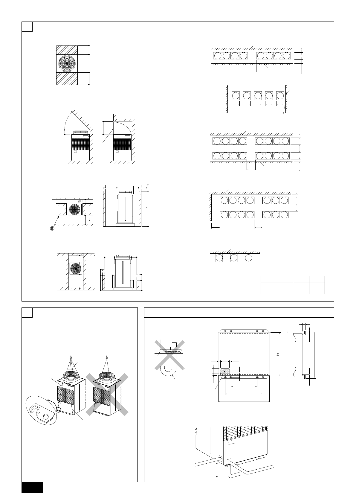
4. Space required around unit
[Fig. 4.0.1] (P.2)
<A> Top view <B> Side view
<C> When there is little space up to an obstruction
A Front B No restrictions on wall height (left and right)
C Air outlet guide (Procured at the site) D Must be open
E Wall height (H) F No restrictions on wall height
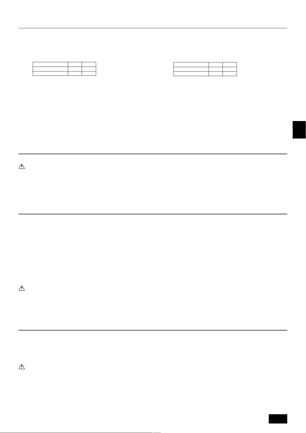
L1 L2
PU(H)Y-YMF 450 250
PU(H)Y-P-YMF 450 450
(1) Basic space required
A space of at least 250 mm is necessary at the back for inlet air. Taking servicing,
etc. from the rear into account, a space of about 450 mm should be provided, the
same as at the front.
(2) When there is an obstruction above the unit
(3) When inlet air enters from right and left sides of unit
• W all heights (H) of the front and the back sides shall be within o ver all height of
unit.
• When the total height is e xceeded, add the “h” dimension of the Fig. 4.0.1 to L
and L2.
(4) When unit is surrounded by walls
Note:
• Wall heights (H) of the front and the back sides shall be within overall
height of unit.
• If the panel height is exceeded, ad d the “h” dimension of the Fig. 4.0.1 to
L
1 and L2.
PU(H)Y-YMF 450 250
PU(H)Y-P-YMF 450 450
Example: When h is 100,
(5) Collective installation and continuous installation
• Space required for collective installation and continuous installation:
• Open in the two directions.
• In case wall height (H) exceeds overall height of unit, add “h” dimension (h =
1
• If there is a wall at both the front and the rear of the unit, install up to f our units
the L
1 dimension becomes 450 + 100 = 550 mm.
When installing several units, lea ve the space betw een each b loc k below considering passage for air and people.
wall height <H> – overall height of unit) to * marked dimension.
consecutively in the side direction and provide a space of 1000 mm or more as
inlet space/passage space for each four units.
L1 L2
5. Lifting method and weight of product
[Fig. 5.0.1] (P.2)
Caution:
Be very careful to carry product.
- Do not have only one person to carry product if it is more than 20 kg.
- PP bands are used to pack some products. Do not use them as a mean for transportation because they are dangerous.
- Do not touch heat exchanger fins with your bare hands. Otherwise you may get a cut in your hands.
- T ear plastic packaging bag and scrap it so that children cannot play with it. Otherwise plastic packaging bag may suffocate children to death.
- When carrying in outdoor unit, be sure to support it at four points. Carrying in and lifting with 3-point support may make outdoor unit unstable, resulting in a fall of it.
GB
D
F
6. Installation of unit
6.1. Installation
[Fig. 6.1.1] (P.2)
A M10 anchor bolt procured at the site. B Corner is not seated.
• Fix unit tightly with bolts so that unit will not fall down due to earthquake or
gust.
• Use concrete or angle for foundation of unit.
• Vibration ma y be transmitted to the installation section and noise and vibration
may be generated from the floor and walls, depending on the installation conditions. Therefore, provide ample vibrationproofing (cushion pads, cushion
frame, etc.).
• Be sure that the corners are firmly seated. If the corners are not firmly seated,
the installation feet may be bent.
Warning:
• Be sure to install unit in a place strong enough to withstand its weight.
Any lack of strength may cause unit to fall down, resulting in a personal
injury.
• Have installation w ork in order to protect against a str ong wind and earthquake.
7. Refrigerant piping installation
Connecting the piping is a terminal-branch type in which refrigerant piping from
the outdoor unit is branched at the terminal and connected to each of the indoor
units.
The method of connection consists of flare connections at the indoor units, flange
connections for the piping of the outdoor unit and flare connections for the liquid
piping. Note that the branched sections are brazed.
Warning:
Always use extreme care to prevent the refrigerant gas (R407C or R22) from
leaking while using fire or flame. If the refrigerant gas comes in contact with
the flame from any source, such as a gas stove, it breaks down and generates a poisonous gas which can cause gas poisoning. Never weld in an
unventilated room. Always conduct an inspection for gas leakage after installation of the refrigerant piping has been completed.
Any installation deficiency may cause unit to fall down, resulting in a
personal injury.
When building the foundation, give full attention to the floor strength, drain water
disposal <during operation, drain water flows out of the unit>, and piping and wiring routes.
Down piping and down wiring precautions
When down piping and down wiring are performed, be sure that foundation and
base work does not block the base through holes. When do wn piping is performed,
make the foundation at least 100 mm high so that the piping can pass under the
bottom of the unit.
[Fig. 6.1.2] (P.2)
A Bottom piping through hole B (bolt hole)
C (bolt hole for old models)
6.2. Connecting direction for refrigerant piping
[Fig. 6.2.1] (P.2)
7.1. Caution
1 Use the following materials for refrigeration piping.
• Material: Use refrigerant piping made of phosphorus deoxidized copper.
In addition, be sure that the inner and outer surfaces of the pipes are clean
and free of hazardous sulphur, oxides, dust/dirt, shaving particles, oils,
moisture, or any other contaminant. (For R407C models)
2 Commercially available piping often contains dust and other materials. Always
blow it clean with a dry inert gas.
3 Use care to prevent dust, water or other contaminants from entering the piping
during installation.
4 Reduce the number of bending portions as much as possible, and make bend-
ing radius as big as possible.
5 Always observe the restrictions on the refrigerant piping (such as rated length,
the difference between high/low pressures, and piping diameter). F ailure to do
so can result in equipment failure or a decline in heating/cooling performance.
E
INL
PGRRUTR
7
Page 8
6 The City Multi Series Y will stop due an abnormality due to excessiv e or insuf-
ficient coolant. At such a time, always properly charge the unit. When servicing, always check the notes concerning pipe length and amount of additional
refrigerant at both locations, the refrigerant volume calculation table on the
back of the service panel and the additional refrigerant section on the labels
for the combined number of indoor units.
7 Use liquid refrigerant to fill the system.
8 Never use refrigerant to perform an air purge. Always e vacuate using a v acuum
pump.
9 Always insulate the piping properly. Insufficient insulation will result in a de-
cline in heating/cooling performance, water drops from condensation and other
such problems.
0 When connecting the refr igerant piping, make sure the ball valve of the out-
door unit is completely closed (the factory setting) and do not operate it until
the refrigerant piping for the outdoor and indoor units has been connected, a
refrigerant leakage test has been performed and the evacuation process has
been completed.
A Always use a non-oxidizing brazing material for brazing the parts. If a non-
oxidizing brazing material is not used, it could cause clogging or damage to
the compressor unit.
B Never perform outdoor unit piping connection work when it is raining.
Warning:
GB
When installing and moving the unit, do not charge it with refrigerant other
than the refrigerant specified on the unit.
- Mixing of a different refrigerant, air, etc. may cause the refrigerant cycle to malfunction and result in severe damage.
D
Caution:
• Use a vacuum pump with a re verse flow check v alve. (For R407C models)
- If the vacuum pump does not have a reverse flow check valve, the vacuum
pump oil may flow back into the refrigerant cycle and cause deterioration of
F
the refrigerator oil and other trouble.
• Do not use the tools shown below used with conventional refrigerant.
(For R407C models)
(Gauge manifold, charge hose, gas leak detector, check valve, refrigerant charge base, vacuum gauge, refrigerant recovery equipment)
- Mixing of conventional refrigerant and refrigerator oil may cause the refrig-
erator oil to deteriorate.
- Mixing of water will cause the refrigerator oil to deteriorate.
- R407C refrigerant does not contain any chlorine. Therefore , gas leak detec-
tors for conventional refrigerants will not react to it.
• Manage the tools more carefully than normal. (For R407C models)
- If dust, dirt, or water gets in the refrigerant cycle, the refrigerator oil will
deteriorate.
• Never use existing refrigerant piping. (For R407C models)
- The large amount of chlorine in conventional refrigerant and refrigerator oil
in the existing piping will cause the new refrigerant to deteriorate.
• Store the piping to be used during installation indoors and keep both
ends of the piping sealed until just before brazing.
- If dust, dirt, or water gets into the refrigerant cycle, the oil will deteriorate and
the compressor may fail.
• Do not use a charging cylinder. (For R407C models)
- Using a charging cylinder may cause the refrigerant to deteriorate.
• Do not use special detergents for washing piping.
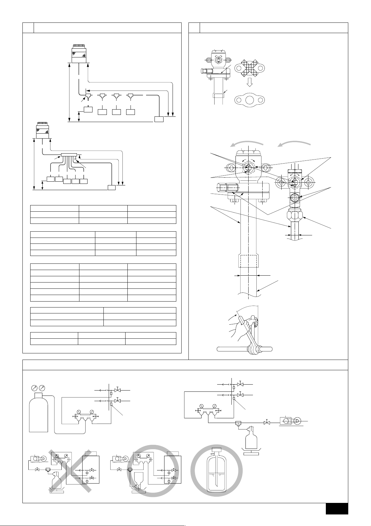
7.2. Refrigerant piping system
Connection Example
[Fig. 7.2.1] (P.3)
Å Liquid pipe ı Gas pipe
Ç Total capacity of indoor units Î Model number
‰ Downstream Unit Model Total Ï Branch Kit Model
Ì 4-Branching Header Ó 7-Branching Header
¬ 10-Branching Header
A Outdoor Unit B First Branch
C Indoor unit D Cap
8. Additional Refrigerant Charge
At the time of shipping, the outdoor unit is charged with the refrigerant. As this
E
charge does not include the amount needed for extended piping, additional charging for each refrigerant line will be required on site. In order that future servicing
may be properly provided, always keep a record of the size and length of each
refrigerant line and the amount of additional charge by writing it in the space provided on the outdoor unit.
INL
8.1. Calculation of Additional Refrigerant
Charge
• Calculate the amount of additional charge based on the length of the piping
extension and the size of the refrigerant line.
• Use the table to the right as guide to calculating the amount of additional charg-
ing and charge the system according.
• If the calculation results of the calculation result in a fraction of less than 0.1 kg.
For example, if the result of the calculation was 10.62 kg, round the result up to
10.7 kg.
PGRRUTR
<Additional Charge>
Additional
refrigerant charge
(kg)
<Example>
Indoor 1: 40 A: ø12.7 40 m a: ø6.35 10 m
2: 100 B: ø9.52 10 m b: ø9.52 5 m
3: 40 C: ø9.52 15 m c: ø6.35 10 m
4: 32 d: ø6.35 10 m
5: 63 e: ø9.52 10 m
The total length of each liquid line is as follows:
ø12.7: A = 40 m
ø9.52: B + b + e = 10 + 5 + 10 = 25 m
ø6.35: a + c + d = 10 + 10 + 10 = 30 m
Therefore,
<Calculation example>
Additional refrigerant charge
= 40 × 0.12 + 25 × 0.06 + 30 × 0.024 + 2 = 9.02 kg
Value of α
Total capacity of connecting indoor units α
Liquid pipe size
Total length of
=+++ α
ø12.7 × 0.12
(m) × 0.12 (kg/m)
to Model 80 1.0 kg
Models 81 to 160 1.5 kg
Models 161 to 325 2.0 kg
Liquid pipe size
Total length of
ø9.52 × 0.06
(m) × 0.06 (kg/m)
Liquid pipe size
Total length of
ø6.35 × 0.024
(m) × 0.024 (kg/m)
At the
conditions
below:
8.2. Caution for piping connection/valve
operation
• Conduct piping connection and valve operation accurately.
• The gas side connecting pipe is being assembled for shipment.
1 For brazing to the connecting pipe with flange, remove the connecting pipe
with flange from the ball valve, and braze it at the outside of the unit.
2 Dur ing the time when removing the connecting pipe with flange, remove
the seal attached on the back side of this sheet and paste it onto the flange
surface of the ball valve to prevent the entry of dust into the valve.
3 The refrigerant circuit is closed with a round, close-packed packing at the
shipment to prevent gas leak between flanges. As no operation can be
done under this state, be sure replace the packing with the hollow packing
attached at the piping connection.
4 At the mounting of the hollow packing, wipe off dust attached on the flange
sheet surface and the packing. Coat refrigerating machine oil (Ester oil,
ether oil or alkylbenzene [small amount]) onto both surfaces of the packing.
[Fig. 8.2.1] (P.3)
• After ev acuation and refrigerant charge , ensure that the handle is fully open. If
operating with the valve closed, abnormal pressure will be imparted to the
high- or low-pressure side of the refrigerant circuit, giving damage to the compressor, four-w a y valve, etc.
• Determine the amount of additional refrigerant charge by using the formula,
and charge refrigerant additionally through the service port after completing
piping connection work.
• After completing work, tighten the service port and cap securely not to gener-
ate gas leak.
[Fig. 8.2.2] (P.3)
<A> [Ball valve (gas side)]
(This figure shows the valve in the fully open state.)
<B> [Ball valve (liquid side)]
A Valve stem
[Fully closed at the factory, when connecting the piping, when evacuating, and
when charging additional refrigerant. Open fully after the operations above are
completed.]
B Stopper pin [Prevents the valve stem from turning 90° or more.]
C Packing (Accessory)
[Manufacturer: Nichiasu corporation]
[T ype: T/#1991-NF]
D Connecting pipe (Accessory)
8
Page 9

[Use packing and securely install this pipe to the valve flange so that gas leakage
will not occur. (Tightening torque: 25 N·m (250 kg·cm)) Coat both surfaces of the
packing with refrigerator oil (Ester oil, ether oil or alkylbenzene [small amount]).]
E Open (Operate slowly)
F Cap, copper packing
[Remove the cap and operate the valve stem. Always reinstall the cap after operation is completed. (Valve stem cap tightening torque: 25 N·m (250 kg·cm) or
more)]
G Service port
[Use this port to evacuate the refrigerant piping and add an additional charge at
the site.
Open and close the port using a double-ended wrench.
Always reinstall the cap after operation is completed. (Service port cap tightening
torque: 14 N·m (140 kg·cm) or more)]
H Flare nut
[Tightening torque: 55 N·m (550 kg·cm)
Loosen and tighten this nut using a double-ended wrench.
Coat the flare contact surface with refrigerator oil (Ester oil, ether oil or alkylbenzene
[small amount]).]
I ø12.7
J ø25.4 (PU(H)Y-(P)200)
ø28.58 (PU(H)Y-(P)250)
K Field piping
[Braze to the connecting pipe. (When brazing, use unoxidized brazing.)]
L Close-packed packing
M Hollow packing
Appropriate tightening torque by torque wrench:
Copper pipe external dia. (mm) Tightening torque (N·m) / (kg·cm)
Tightening angle standard:
Pipe diameter (mm) Tightening angle (°)
ø6.35, ø9.52 60 to 90
ø12.7, ø15.88 30 to 60
[Fig. 8.2.3] (P.3)
ø6.35 14 to 18 / 140 to 180
ø9.52 35 to 42 / 350 to 420
ø12.7 50 to 57.5 / 500 to 575
ø15.88 75 to 80 / 750 to 800
ø19.05 100 to 140 / 1000 to 1400
ø19.05 20 to 35
Note:
If a torque wrench is not available, use the following method as a standard:
When you tighten the flare nut with a wrench, you will reach a point where
the tightening torque will abrupt increase. T urn the flare n ut beyond this point
by the angle shown in the table above.
Caution:
• Always remove the connecting pipe from the ball valve and braze it outside the unit.
- Brazing the connecting pipe while it is installed will heat the ball valve and
cause trouble or gas leakage. The piping, etc. inside the unit may also be
burned.
• Use ester oil, ether oil or alkylbenz ene (small amount) as the refrigerator
oil to coat flares and flange connections. (For R407C models)
- The refrigerator oil will degrade if it is mixed with a large amount of mineral
oil.
8.3. Airtight test, e vacuation, and refrigerant
charging
1 Airtight test
Perform with the stop valv e of the outdoor unit closed, and pressurize the connection piping and the indoor unit from the service port provided on the stop
valve of the outdoor unit. (Always pressurize from both the liquid pipe and the
gas pipe service ports.)
[Fig. 8.3.1] (P.3)
A Nitrogen gas B To indoor unit C System analyzer
D Lo Knob E Hi Knob F Stop valve
G Liquid pipe H Gas pipe I Outdoor unit
J Service port
<For R407C models>
The method of conducting the airtight test is basically the same as for R22 models.
However , since the restrictions have a large aff ect on deterioration of the refrigerator oil, always observe them. Also, with nonazeotropic refrigerant (R407C, etc.),
gas leakage causes the composition to change and affects performance. Therefore, perform the airtightness test cautiously.
GB
D
F
E
Airtight test procedure
1. Nitrogen gas pressurization
(1) After pressurizing to the design pressure (2.94 MPa) using nitrogen gas, let stand for about
one day. If the pressure does not drop, airtightness is good.
However, if the pressure drops, since the leaking point is unknown, the following bubble test
may also be performed.
(2) After the pressurization described above, spray the flare connection parts, brazed parts, flanges,
and other parts that may leak with a bubbling agent (Kyuboflex, etc.) and visually check for
bubbles.
(3) After the airtight test, wipe off the bubbling agent.
2. Pressurization using refrigerant gas and nitrogen gas
(1) Pressurizing to a gas pressure of approximately 0.2 MPa, pressurize to the design pressure
(2.94 MPa) using nitrogen gas.
However, do not pressurize at one time. Stop during pressurization and check that the pressure does not drop.
(2) Check for gas leaks by checking the flare connection parts, brazed parts, flanges, and other
parts which may leak using an R407C compatible electric leak detector.
(3) This test may be used together the with bubble type gas leak test.
2 Evacuation
Evacuate with the ball valve of the outdoor unit closed and evacuate both the
connection piping and the indoor unit from the service port provided on the ball
valve of the outdoor unit using a vacuum pump. (Always evacuate from the
service port of both the liquid pipe and the gas pipe.) After the vacuum reaches
650 Pa [abs], continue evacuation for at least one hour or more.
* Never perform air purging using refrigerant.
[Fig. 8.3.2] (P.3)
A System analyzer B Lo Knob C Hi Knob
D Ball valve E Liquid pipe F Gas pipe
G Service port H Three-way joint I Valve
J Valve K Cylinder L Scale
M Vacuum pump
Note:
• Always add an appropriate amount of refrigerant. Also always seal the
system with liquid refrigerant. T oo muc h or too little refrigerant will cause
trouble.
• Use a gauge manifold, charging hose, and other parts for the refrigerant
indicated on the unit.
• Use a graviometer. (One that can measure down to 0.1 kg.)
• Use a vacuum pump with a re verse flow check v alve. (For R407C models)
3 Refrigerant Charging (For R407C models)
Restriction
• If a flammable gas or air (oxygen) is used as the pressurization
gas, it may catch fire or explode.
• Do not use a refrigerant other than that indicated on the unit.
• Sealing with gas from a cylinder will cause the composition of
the refrigerant in the cylinder to change. (For R407C models)
• Use a pressure gauge, charge box, and other parts especially for
R407C. (For R407C models)
• An electric leak detector for R22 cannot detect leaks of R407C.
• Do not use a haloid torch. (Leaks cannot be detected.)
(Recommended vacuum gauge: ROBINAIR 14830A Thermistor Vacuum
Gauge)
Also use a vacuum gauge that reaches 0.5 Torr or greater after operating
for five minutes.
Since the refrigerant used with the unit is nonazerotropic, it must be charged in
the liquid state. Consequently, when charging the unit with refrigerant from a
cylinder, if the cylinder does not have a syphon pipe , charge the liquid refrigerant by turning the cylinder upside-down as shown below. If the cylinder has a
syphon pipe like that shown in the figure at the right, the liquid refrigerant can
be charged with the cylinder standing upright. Therefore, giv e careful attention
to the cylinder specifications. If the unit should be charged with gas refrigerant,
replace all the refrigerant with new refrigerant. Do not use the refrigerant remaining in the cylinder.
[Fig. 8.3.3] (P.3)
INL
PGRRUTR
9
Page 10
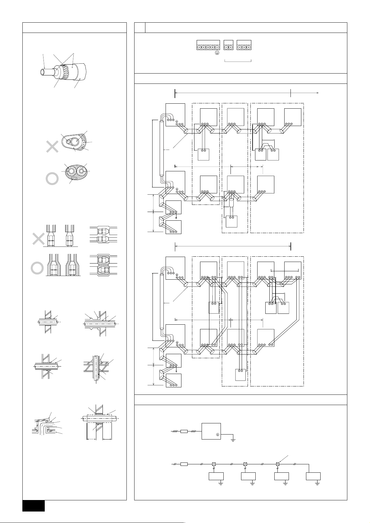
8.4. Thermal insulation of refrigerant piping
Be sure to give insulation work to refrigerant piping by covering liquid pipe and gas
pipe separately with enough thickness heat-resistant polyethylene , so that no gap
is observed in the joint between indoor unit and insulating material, and insulating
materials themselves. When insulation work is insufficient, there is a possibility of
condensation drip, etc. Pay special attention to insulation work to ceiling plenum.
[Fig. 8.4.1] (P.4)
A Steel wire B Piping
C Asphaltic oily mastic or asphalt D Heat insulation material A
E Outer covering B
Heat
insulation
material A
Outer
covering B
Note:
• When using polyeth ylene cover as covering material, asphalt roofing shall
not be required.
• No heat insulation must be provided for electric wires.
GB
Glass fiber + Steel wire
Adhesive + Heat - resistant polyethylene foam + Adhesive tape
Indoor Vinyl tape
Floor exposed Water-proof hemp cloth + Bronze asphalt
Outdoor
Water-proof hemp cloth + Zinc plate + Oily
paint
9. Wiring
[Fig. 8.4.2] (P.4)
A Liquid pipe B Gas pipe C Electric wire
D Finishing tape E Insulater
[Fig. 8.4.3] (P.4)
Penetrations
[Fig. 8.4.4] (P.4)
<A> Inner wall (concealed) <B> Outer wall
<C> Outer wall (exposed) <D> Floor (fireproofing)
<E> Roof pipe shaft
<F> Penetrating portion on fire limit and boundary wall
A Sleeve B Heat insulating material
C Lagging D Caulking material
E Band F Waterproofing laye
G Sleeve with edge H Lagging material
I Mortar or other incombustible caulking
J Incombustible heat insulation material
When filling a gap with mortar, cover the penetration part with steel plate so that
the insulation material will not be caved in. F or this part, use incombustible materials for both insulation and covering. (Vinyl covering should not be used.)
D
9.1. Caution
1 Follow ordinance of your governmental organization for technical standard re-
lated to electrical equipment, wiring regulations and guidance of each electric
power company.
2 Wiring for control (hereinafter referred to as transmission line) shall be (5 cm or
F
more) apart from power source wiring so that it is not influenced by electric
noise from power source wiring. (Do not insert transmission line and power
source wire in the same conduit.)
3 Be sure to provide designated grounding work to outdoor unit.
E
4 Give some allowance to wiring for electrical part box of indoor and outdoor
units, because the box is sometimes removed at the time of service work.
5 Never connect the main power source to terminal block of transmission line. If
connected, electrical parts will be burnt out.
6 Use 2-core shield cable for transmission line. If transmission lines of different
INL
systems are wired with the same multiplecore cable, the resultant poor transmitting and receiving will cause erroneous operations.
7 Only the transmission line specified should be connected to the terminal block
for outdoor unit transmission.
(Transmission line to be connected with indoor unit : Terminal block TB3 for
transmission line, Other : Terminal block TB7 for centralized control)
Erroneous connection does not allow the system to operate.
8 In case to connect with the upper class controller or to conduct group opera-
tion in different refrigerant systems, the control line for transmission is required
between the outdoor units each other.
PGRRUTR
Connect this control line between the terminal blocks for centralized control.
(2-wire line with no polarity)
When conducting group operation in different refrigerant systems without connecting to the upper class controller, replace the insertion of the short circuit
connector from CN41 of one outdoor unit to CN40.
9 Group is set by operating the remote controller.
9.2. Control box and connecting position of
wiring
1. Connect the indoor unit transmission line to transmission terminal block (TB3),
or connect the wiring between outdoor units or the wiring with the central control system to the central control terminal block (TB7).
When using shielded wiring, connect shield ground of the indoor unit transmission line to the earth screw (
outdoor units and the central control system transmission line to the shield (S)
terminal of the central control terminal block (TB7) shield (S) terminal. In addition, in the case of outdoor units whose power supply connector CN41 has
been replaced by CN40, the shield terminal (S) of terminal block (TB7) of the
central control system should also be connected to the ground (
[Fig. 9.2.1] (P.4)
A Power source B Transmission line
2. Conduit mounting plates (ø27) are being provided. Pass the power supply and
transmission wires through the appropriate knock-out holes, then remove the
knock-out piece from the bottom of the terminal box and connect the wires.
3. Fix power source wiring to terminal box by using buffer bushing for tensile
force (PG connection or the like).
) and connect shield ground of the line between
).
9.3. Wiring transmission cables
1 Types of control cables
1. Wiring transmission cables
• Types of transmission cables: Shielding wire CVVS or CPEVS
• Cable diameter: More than 1.25 mm
• Maximum wiring length: Within 200 m
2. Remote control cables
Kind of remote control cable
Cable diameter
Remarks
2 Wiring examples
• Controller name, symbol and allowable number of controllers.
Name
Outdoor unit controller
Indoor Unit Controller
Remote Controller
2
2-core cable (unshielded)
0.3 to 1.25 mm
When 10 m is exceeded, use cable with the
same specifications as (1) Transmission line
wiring
Symbol
OC
IC
RC
2
Allowable number of controllers
Two to ten controllers for one OC
Maximum of two per group
Example of a group operation system with multiple outdoor units (Shielding wires and address setting are
necessary.)
<Examples of Transmission Cable Wiring>
[Fig. 9.3.1] M-NET Remote Controller (P.4)
[Fig. 9.3.2] MA Remote Controller (P.4)
A Group 1 B Group 3 C Group 5 D Shielded Wire E Sub Remote Controller
( ) Address
10
Page 11
<Wiring Method and Address Settings>
a. Always use shielded wire when making connections between the outdoor unit (OC) and the indoor unit (IC), as well for all OC-OC, and IC-IC wiring intervals.
b. Use feed wiring to connect terminals M1 and M2 and the ground terminal on the transmission cable terminal block (TB3) of each outdoor unit (OC) to terminals M1, M2
and terminal S on the transmission cable block of the indoor unit (IC).
c. Connect terminals 1 (M1) and 2 (M2) on the transmission cable terminal block of the indoor unit (IC) that has the most recent address within the same group to the
terminal block on the remote controller (RC).
d. Connect together terminals M1, M2 and terminal S on the terminal block for central control (TB7) for the outdoor unit (OC).
e. On one outdoor unit only, change the jumper connector on the control panel from CN41 to CN40.
f. Connect the terminal S on the terminal block for central control (TB7) for the outdoor unit (OC) f or the unit into which the jumper connector was inserted into CN40 in Step
above to the ground terminal
g. Set the address setting switch as follows.
* To set the outdoor unit address to 100, the outdoor address setting switch must be set to 50.
Unit Range Setting Method
IC (Main) 01 to 50 Use the most recent address within the same group of indoor units
IC (Sub) 01 to 50
Outdoor Unit 51 to 100 Use the most recent address of all the indoor units plus 50
M-NET R/C (Main) 101 to 150 Set at an IC (Main) address within the same group plus 100
M-NET R/C (Sub) 151 to 200 Set at an IC (Main) address within the same group plus 150
MA R/C – Unnecessary address setting (Necessary main/sub setting)
h. The group setting operations among the multiple indoor units is done by the remote controller (RC) after the electrical power has been turned on.
<Permissible Lengths>
1 M-NET Remote controller
• Max length via outdoor units: L
• Max transmission cable length: L
• Remote controller cable length:r
2 MA Remote controller
• Max length via outdoor unit (M-NET cable): L
• Max transmission cable length (M-NET cable): L
• Remote controller cable length:c
in the electrical component box.
Use an address, other than that of the IC (Main) from among the units within the same group of indoor units. This must be
in sequence with the IC (Main)
1+L2+L3+L4 and L1+L2+L3+L5 and L1+L2+L6+L7
1 and L3+L4 and L3+L5 and L6 and L2+L6 and L7
1, r2, r3, r4
If the length exceeds 10 m, use a 1.25 mm
maximum length and overall length.
1+c2 and c1+c2+c3+c4
10 m (0.3 to 1.25 mm2)
=
1+L2+L3+L4 and L1+L2+L6+L7
1 and L3+L4 and L6 and L2+L6 and L7
200 m (0.3 to 1.25 mm2)
=
2
shielded wire. The length of this section (L8) should be included in the calculation of the
=
500 m (1.25 mm2 or more)
=
200 m (1.25 mm2 or more)
=
500 m (1.25 mm2 or more)
200 m (1.25 mm2 or more)
=
9.4. Wiring of main power supply and equipment capacity
Schematic Drawing of Wiring (Example)
[Fig. 9.4.1] (P.4)
A Switch (Breakers for Wiring and Current Leakage) B Outdoor Unit
C Pull Box D Indoor Unit
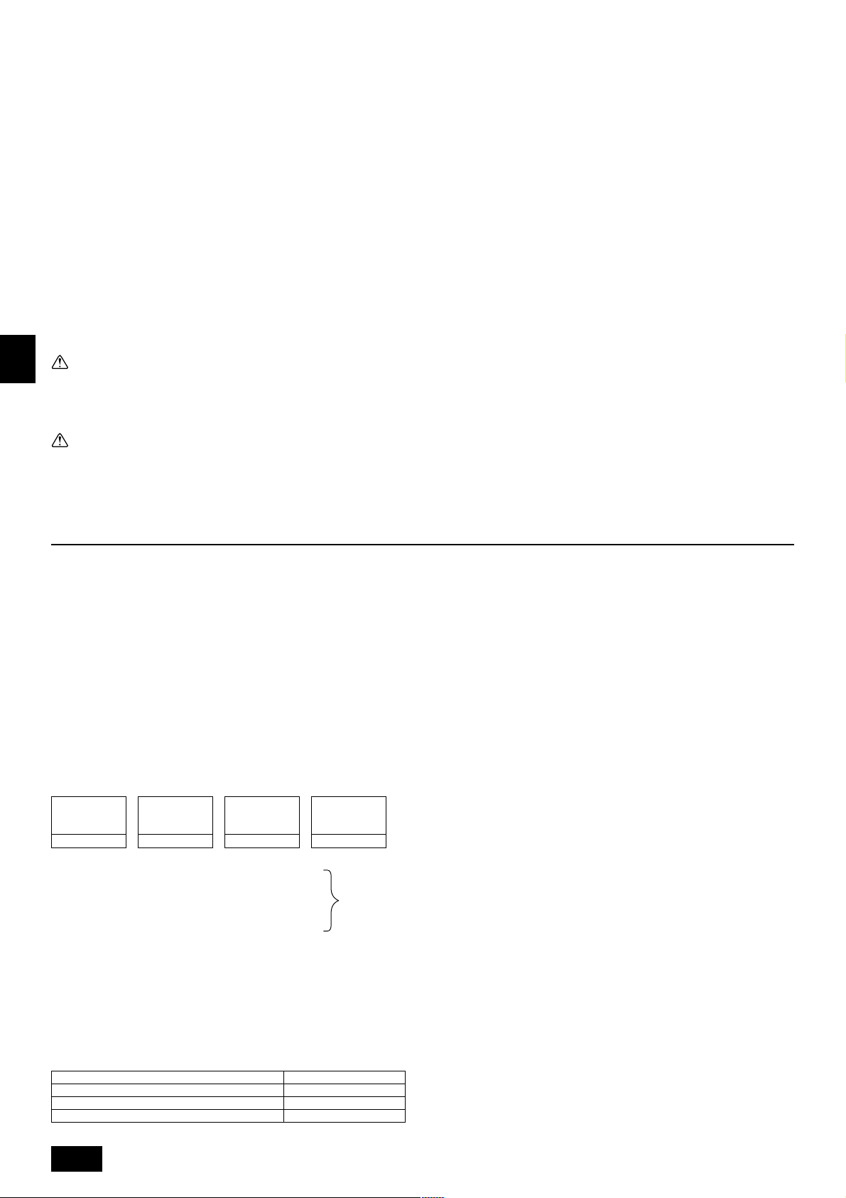
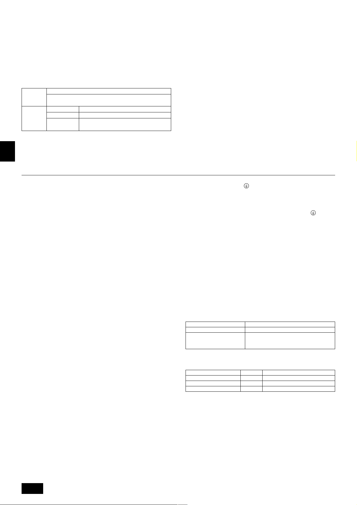
Thickness of Wire for Main Power Supply and On/Off Capacities
Minimum Wire Thickness (mm
Model
Outdoor
Unit
1. Use a separate power supply for the outdoor unit and indoor unit.
2. Bear in mind ambient conditions (ambient temperature,direct sunlight, rain water,etc.) when proceeding with the wiring and connections.
3. The wire size is the minimum value for metal conduit wiring. The power cord size should be 1 rank thicker consideration of voltage drops.
Make sure the power-supply voltage does not drop more than 10 %.
4. Specific wiring requirements should adhere to the wiring regulations of the reglon.
5. Power supply cords of parts of appliances for outdoor use shall not be lighter than polychloroprene sheathed fle xible cord (design 245 IEC57). For example,
use wiring such as YZW.
(P)200
(P)250
Indoor Unit
Main Cable
4.0
6.0
1.5
Branch Capacity Fuse
–
–
1.5
Warning:
• Be sure to use specified wires to connect so that no external force is imparted to terminal connections. If connections are not fixed firmly, it may cause
heating or fire.
• Be sure to use the appropriate type of overcurrent protection switch. Note that generated overcurrent may include some amount of direct current.
2
)
Ground
4.0
6.0
1.5
32
40
16
Switch (A)
Breaker for
Wiring (NFB)
32
40
16
40 A
40 A
20 A
Breaker for Current Leakage
30 A 100 mA 0.1sec. or less
40 A 100 mA 0.1sec. or less
20 A 30 mA 0.1sec. or less
GB
D
F
E
INL
PGRRUTR
Caution:
• Some installation site may require attachment of an earth leakage breaker. If no earth leakage breaker is installed, it may cause an electric shock.
• Do not use anything other than breaker and fuse with correct capacity. Using fuse and wire or copper wire with too large capacity may cause a malfunction
of unit or fire.
11
Page 12

10.Test run
10.1. The following phenomena do not represent trouble (emergency)
Phenomenon
Indoor unit does not the perform cooling (heating) operation.
The auto vane runs freely.
Fan setting changes during heating.
Fan stops during heating operation.
Fan does not stop while operation has been
stopped.
No setting of fan while start SW has been
turned on.
Outdoor unit does not operate by turning
switch on.
GB
Indoor unit remote controller shows “HO” in-
dicator for about two minutes when turning
ON universal power supply.
D
Drain pump does not stop while unit has been
stopped.
Drain pump continues to operate while unit
has been stopped.
F
Display of remote controller
“Cooling (heating)” flashes
Normal display
Normal display
Defrost display
No lighting
Heat ready
Normal display
“HO” flashes
Light out
Cause
When another indoor unit is performing the heating (cooling) operation, the cooling (heating) operation is not performed.
Because of the control operation of auto vane, it may change over to horizontal
blow automatically from the downward blow in cooling in case the downward
blow operation has been continued for 1 hour . At defrosting in heating, hot adjusting and thermostat OFF, it automatically changes over to horizontal blow.
Ultra-low speed operation is commenced at thermostat OFF.
Light air automatically changes over to set value by time or piping temperature at
thermostat ON.
The fan is to stop during defrosting.
Fan is to run for 1 minute after stopping to e xhaust residual heat (only in heating).
Ultra low-speed operation for 5 minutes after SW ON or until piping temperature
becomes 35°C, low speed operation for 2 min utes thereafter, and then set notch
is commenced. (Hot adjust control)
When the outdoor unit is being cooled and the refrigerant is resting, warming up
operation is performed for at least 35 minutes to warm the compressor.
During this time, only the fan operates.
System is being driven.
Operate remote controller again after “HO” disappear.
After a stop of cooling operation, unit continues to operate drain pump for three
minutes and then stops it.
Unit continues to operate drain pump if drainage is generated, even during a
stop.
E
INL
PGRRUTR
12
Page 13
СОДЕРЖАНИЕ
1. Меры предосторожности ....................................................................... 71
1.1. Перед установкой прибора и выполнением
электроработ ......................................................................... 71
1.2. Меры предосторожности для приборов, в которых
используется хладагент R407C ........................................... 72
1.3. Перед выполнением установки ............................................ 72
1.4. Выполнение электроработ до установки
(перемещения) ....................................................................... 72
1.5. Перед началом пробной эксплуатации ................................ 72
2. Использование в сочетании с внутренними приборами ..................... 73
3. Поставляемые приспособления ............................................................ 73
4. Пространсво вокруг прибора ................................................................. 73
5. Перемещение прибора и масса изделия .............................................. 73
6. Установка прибора ................................................................................. 73
6.1. Установка .............................................................................. 73
6.2. Направление подсоединения труб хладагента ................... 74
7. Установка труб хладагента .................................................................... 74
7.1. Осторожно .............................................................................. 74
1. Меры предосторожности
1.1. Перед установкой прибора и
выполнением электроработ
s До установки прибора убедитесь, что Вы прочли все
“Меры предосторожности”.
s “Меры предосторожности” содержат важные указания
по технике безопасности. Убедитесь, что Вы им следуете.
Символика, используемая в тексте
Предупреждение:
Описывает меры предосторожности, необходимые для предотвращения
получения травмы или гибели пользователя.
Внимание:
Описывает меры предосторожности, необходимые для предотвращения
повреждения прибора.
Символика, используемая в иллюстрациях
: Указывает действие, которое следует избегать.
: Указывает на важную инструкцию.
: Указывает, что данная часть должна быть заземлена.
: Опасайтесь электрошока. (Этот символ указан на этикетке основного
прибора.) <Цвет: желтый>
Предупреждение:
Внимательно прочтите текст на этикетках главного прибора.
Предупреждение:
• Обратитесь к дилеру или квалифицированному технику для
выполнения установки кондиционера воздуха.
- Неправильная установка, выполненная пользователем, может вызвать
утечку воды, электрошок или пожар.
• Устанавливайте прибор в месте, способном выдержать его вес.
- Недостаточно прочное основание может вызвать падение прибора и
привести к т равме.
• Используйте указанные кабели для электропроводки. Выполняйте
соединения с соблюдением требований безопасности, чтобы кабели
не приводили к повреждению клемм.
- Недостаточно надежные соединения могут вызвать перегрев и стать
причиной пожара.
• Подготовьтесь к сильным ветрам и землетрясениям и установите
прибор в соответствующем месте.
- Неправильная установка может вызвать падение прибора и причинить
травму.
• Используйте фильтры и другие дополнительные принадлежности
только производства компании Mitsubishi Electric.
- Обратитесь к услугам квалифицированногоу техника для установки
дополнительных приспоосблений. Неправильная установка,
выполненная пользователем, может вызвать утечку воды, электрошок
или пожар.
• Никогда не ремонтируйте прибор самостоятельно. Если требуется
ремонт кондиционера воздуха, обратитесь к дилеру.
- Если прибор неправильно отремонтирован, это может вызвать утечку
воды, электрошок или пожар.
• Не прикасайтесь к лопастям теплообменника.
- Неправильное обращение с прибором может привести к травме.
7.2. Система труб хладагента ...................................................... 74
8. Дополнительный заряд хладагента ....................................................... 74
8.1. Расчет дополнительного заряда хладагента....................... 74
8.2. Меры предосторожности при подсоединении
труб/управлении клапанами................................................. 75
8.3. Тест на герметичность, продувка и
зарядка хладагента .............................................................. 75
8.4. Термоизоляция труб хладагента ........................................... 76
9. Электропроводка ................................................................................... 77
9.1. Осторожно ............................................................................. 77
9.2. Блок управления и положение проводки ............................ 77
9.3. Прокладка кабелей передачи ............................................. 77
9.4. Электропроводка для сетевого питания
и характеристики оборудования .......................................... 78
10. Контрольный запуск ............................................................................... 79
10.1. Указанные ниже явления не являются
неисправностями ................................................................... 79
• При утечке газа охлаждения во время установки проветрите
помещение.
- При контакте газа охлаждения с огнем будут выделяться ядовитые
газы.
• Устанавливайте кондиционер согласно инструкциям, приведенным
в данном Руководстве по установке.
- Неправильная установка может вызвать утечку воды, электрошок или
пожар.
• Все электроработы должны выполняться квалифицированным
лицензированным электриком согласно Электротехническим
Станадартам и Нормам проведения внутренней проводки и
инструкциям, приведенным в данном руководстве; всегда
используйте отдельную схему.
- При недостаточной мощности источника питания или неправильном
выполнении электроработ может возникнуть электрошок или пожар.
• Надежно установите крышку (панель) коробки терминала выводов
наружного прибора.
- Если крышка (панель) коробки терминала выводов не установлена
надлежащим образом, то в наружный прибор может попасть пыль или
вода, что, в свою очередь, может привести к пожару или электрошоку.
• При установке и перемещении кондиционера на другой объект не
заряжайте его другим хладагентом, кроме хладагента R407C или R22,
указанного на приборе.
- При смешении другого хладагента или воздуха с первоначальным
хладагентом может произойти сбой цикла охлаждения и прибор может
быть поврежден.
• Если кондиционер установлен в небольшом помещении, необходимо
принять меры для предотвращения концентрации хладагента свыше
безопасных пределов в случае утечки хладагента.
- Проконсультируйтесь с дилером относительно соответствующих мер
по предотвращению превышения допустимой концетрации. В случае
утечки хладагента и превышения допустимых лимитов концентрации
может возникнуть опасносная ситуация в связи с недостатком
кислорода в помещении.
• При перемещении и повторной установке кондиционера
проконсультируйтесь с дилером или квалифицированным
техником.
- Неправильная установка, выполненная пользователем, может вызвать
утечку воды, электрошок или пожар.
• По завершении установки убедитесь в отсутствии утечки газа
охлаждения.
- При утечке газа охлаждения и попадании его под воздействие
обогревателя, печи, духовки или другого источника тепла могут
образоваться ядовитые газы.
• Не переделывайте и не изменяйте предохранительных установок
на защитных устройствах.
- При коротком замыкании и насильственном включении выключателей
давления, термовыключателей или других элементов, кроме тех,
которые указаны Митцубиси Электрик, может возникнуть пожар или
взрыв.
• Для утилизации данного изделия, пожалуйста, обратитесь к Вашему
дилеру.
• Специалист по установке и специалист по системе обеспечат защиту
от утечки в соответствии с местными стандартами и нормативами.
- При отсутствии местных нормативных актов могут примяняться
следующие стандарты.
• Особое внимание следует уделять таким местам, как подвалам и т.
д., где возможно скопление газа хладагента ввиду того, что он
тяжелее воздуха.
71
GB
D
F
E
INL
PGR
RUTR
Page 14
1.2. Меры предосторожности для
приборов, в которых используется
хладагент R407C
Внимание:
• Не используйте имеющиеся трубы хладагента.
- Использование старых труб хладагента и старого масла охлажднения,
содержащих большие количества хлорина, может привести к порче
масла охлаждения нового прибора.
• Для труб хладагента используйте бесшовные трубы из фосфористой
восстановленной меди и медных сплавов. Кроме этого убедитесь,
что внутренняя и внешняя поверхность труб чистая, без частиц серы,
окисей, пыли/грязи, частиц стружки, масел, влаги или других
загрязнений.
- Загрязнение внутренней поверхности труб хладагента может вызвать
ухудшение остаточного масла охлаждения.
• Храните предназначенные для установки трубы в помещении,
герметически закрытыми с обоих концов до припайки. (Углы и
другие соединнеия храните в пластмассовом пакете.)
- Попадание в цикл охлаждения пыли, грязи или воды, может ухудшить
масло и вызвать проблемы с компрессором.
• Используйте в качестве масла охлаждения масло сложного или
простого эфира или алкинбензол (небольшое количество) для
GB
покрытия раструбов и фланцевых соединений.
- Масло охлаждения испортится при смешивании с большим количеством
минерального масла.
• Используйте для заполнения системы жидкий хладагент.
- При использовании газового хладагента для герметизации системы,
D
F
E
INL
PGR
RUTR
состав хладагента в баллоне изменится, а рабочие показатели прибора
могут ухудшиться.
• Не используйте другие хладагенты, кроме хладагента R407С.
- При использовании другого агента (например, R22), наличие в нем
хлорина может вызвать сбой цикла охлаждения и привести к ухудшению
масла охлаждения.
• Используйте вакуумный насос с контрольным клапаном обратного
хода.
- Масло вакуумного насоса может проникнуть обратно в цикл охлаждения
и привести к ухудшению масла охлаждения.
• Не используйте указанные ниже инструменты с обычным
хладагентом.
(Манифольд, зарядный шланг, детектор обнаружения утечки газа,
конт рольный клапан, основу заряда хладагентом, оборудование для
сбора хладагента.)
- Смешивание обычного хладагента и масла охлаждения с R407С может
вызвать ухудшение масла охлаждения.
- Смешивание воды с R407С может вызвать ухудшение масла
охлаждения.
- Хладагент R407С не содержит хлорина. Поэтому детекторы утечек газа,
предназначенные для обычных хладагентов, не обнаруживают его.
• Не используйте зарядный баллон.
- Использовние зарядного баллона может вызвать ухудшение хладагента.
• Обращайтесь с инструментами особенно внимательно.
- Попадание в цикл охлаждения пыли, грязи или воды может вызвать
ухудшение масла охлаждения.
1.3. Перед выполнением установки
Внимание:
• Не устанавливайте прибор там, где возможна утечка горючего газа.
- При утечке газа и его скоплении около прибора может произойти взрыв.
• Не используйте кондиционер воздуха в местах содержания
продуктов, домашних животных, растений, точных приборов или
предметов искусства.
- Качество продуктов и т.д. может ухудшиться.
• Не используйте кондиционер воздуха в особых условиях.
- Наличие масел, пара, сульфурных испарений и т.д. может вызвать
значительное ухудшение рабочих показателей кондиционера или
повредить его элементы.
• При установке прибора в больнице, на станции связи или в
аналогичном помещении обеспечьте достаточную защиту от шума.
- Преобразовательное оборудование, частный электрогенератор,
высоковольтное медицинское оборудование или оборудование для
радиосвязи могут вызвать сбой в работе кондиционера или его
отключение. С другой стороны, кондиционер может мешать работе
такого оборудования создаваемым шумом, который нарушает ход
медицинских процедур или радиовещания.
• Не устанавливайте прибор на конструкции, которая может стать
причиной утечки.
- При влажности в помещении свыше 80 % или при засорении дренажной
трубы, с внутреннего прибора может капать конденсирующаяся влага.
Выполняйте дренаж одновременно внутреннего прибора и наружного
прибора, когда это требуется.
1.4. Выполнение электроработ до
установки (перемещения)
Внимание:
• Заземлите прибор.
- Не подсоединяйте провод заземления к газовой трубе, водяной трубе,
громоотводу или линии заземления телефонной проводки. При
неправильном заземлении может возникнуть электрошок.
• Обратная фаза линий L (L
ошибки 4103), но обратную фазу линий L и линии N обнаружить
невозможно.
- При подаче электропитания в неправильно соединенную сеть возможна
поломка некоторых электродеталей.
• Проложите сетевой кабель так, чтобы он не был натянут.
- Натяжение может привести к разрыву кабеля и стать источником
перегрева и пожара.
• Установите прерыватель цепи, если требуется.
- Если прерываетль цепи не установлен, это может приветси к
электрошоку.
• Используйте сетевой кабель достаточной мощности напряжения.
- Кабели слишком малой мощности могут прогореть, вызвать перегрев
и пожар.
• Используйте прерыватель цепи и предохранитель указанной
мощности.
- Предохранитель или прерыватель большей мощности или стальной или
медный провод могут вызвать поломку прибора или пожар.
• Не мойте детали кондиционера.
- Мытье деталей кондиционера может вызвать электрошок.
• Проявляйте осторожность, следите, чтобы установочное основание
не было повреждено после длительного использования.
- При неустранении повреждения основания прибор может упасть и
причинить травму или повреждение имущества.
• Проложите дренажные трубы в соответствии с инструкциями в
данном Руководстве по установке для обеспечения надлежащего
дренирования. Оберните трубы термоизоляционным материалом
для предотвращения конденсации.
- Неправильная прокладка дренажных труб может вызвать утечку воды
и повредить мебель и другое имущество.
• Будьте очень внимательным при транспортировке прибора.
- Нельзя, чтобы перемещение прибора выполнял один человек, если вес
прибора превышает 20 кг.
- Для упаковки некоторых изделий используются пластиковые ленты.
Не применяйте их для транспортировки, это опасно.
- Не трогайте лопасти теплообменника голыми руками. Вы можете
порезаться.
- При перемещении наружного прибора подвешивайте его в указанных
точках основания прибора. Также поддерживайте его в четырех точках,
чтобы он не соскользнул.
• Утилизируйте упаковочные материалы с соблюдением правил
безопасности.
- Такие упаковочные материалы, как гвозди и другие металлические или
деревянные части, могут причинить порез и другую травму.
- Удалите пластиковый упаковочный пакет и устраните его так, чтобы
он был недоступен детям. Дети могут задохнуться и умереть, если будут
играть с пластиковым упаковочным пакетом.
1, L2, L3) может быть обнаружена (Код
1.5. Перед началом пробной
эксплуатации
Внимание:
• Подключите электропитание прибора не менее чем за 12 часов до
начала работы.
- Запуск прибора сразу после подключения сетевого питания может
серьезно повредить внутренние части прибора. Сетевой выключатель
должен оставаться во включенном положении в течение всего периода
эксплуатации прибора.
• Не прикасайтесь к выключателям мокрыми руками.
- Прикосновение к выключателю мокрыми руками может вызвать
электрошок.
• Не прикасайтесь к трубам хладагента во время работы и сразу после
выключения прибора.
- В течение и сразу после эксплуатации прибора трубы хладагента могут
быть горячими или холодными, в зависимости от условий протекающего
в трубах, компрессоре и других элементах цикла охлаждения
хладагента. Вы можете обжечь или обморозить руки при прикосновении
к трубам хладагента.
• Не используйте кондиционер воздуха, если его панели и крышки
сняты.
- Вращающиеся, горячие части или части под напряжением могут
причинить травму.
• Не отключайте питание немедленно после выключения прибора.
- Всегда подождите не менее пяти минут до отключения питания. Иначе
может возникнуть утечка воды и другие проблемы.
72
Page 15

2. Использование в сочетании с внутренними приборами
Mодель
Уровень шума
Масса
Максимальное давление хладагента
Внешнее статическое давление
Внутренние блоки
кондиционера
Рабочая температура
Общая мощность
Модель / Количество
PUHY-200 : 219 кг PUY-200 : 218 кг PUHY-250 : 221 кг PUY-250 : 220 кг
PUHY-P200 : 225 кг PUY-P200 : 223 кг PUHY-P250 : 231 кг PUY-P250 : 230 кг
PU(H)Y-(P)200YMF-C PU(H)Y-(P)250YMF-C
56 dB <A> 57 dB <A>
2,94 MПa
0 Пa
50 ~ 130 %
20 ~ 250 / 1 ~ 15 20 ~ 250 / 1 ~ 16
Режим охлаждения: – 5 °CDB ~ 43 °CDB
Режим обогрева: – 15 °CWB ~ 15,5 °CWB
3. Поставляемые приспособления
1 Монтажная арматура × 1 2 Пластина для установки вентиляционной трубы (ø40, ø33, ø27) × 1 3 Винт М4 × 6
4 Соединительная труба × 1 (Соединительная труба подсоединена к прибору.) 5 Уплотнение (Внутренний ø23, внешний ø35) × 1
4. Пространсво вокруг прибора
[Fig. 4.0.1] (P.2)
<A> Вид сверху <B> Вид сбоку
<C> Если расстояние до препятствия малое
A Перед
B Нет ограничений для высоты стен (слева и справа)
C Направляющая выхода воздуха (Поставку требуется организовать на месте)
D Должно быть открыто E Высота стен (Н)
F Нет ограничения для высоты стен
PU(H)Y-YMF 450 250
PU(H)Y-P-YMF 450 450
(1) Основное требуемое пространство
За задней панелью прибора должно быть оставлено не менее 250 мм для
поступления воздуха. Если учесть необходимость доступа для обслуживания
и т.д., то следует оставить приблизительно 450 мм; то же самое относится к
передней панели прибора.
(2) Если имеется препятствие над прибором
(3) Если воздух поступает с правой и с левой стороны прибора
• Высота стен (Н) (спереди и сзади) должна соответствовать общей высоте
прибора.
• В случае превышения общей высоты добавьте расстояние “h” на Fig.
4.0.1 к L
1 и L2.
L1 L2
(4) Если прибор окружают стены
Примечание:
• Высота стен (Н) (спереди и сзади) должна соответствовать общей
высоте прибора.
• В случае превышения высоты панели добавьте расстояние “h” на
Fig. 4.0.1 к L
Пример: Когда h = 100,
(5) Установка ряда приборов в последовательности и непрерывная
установка
• Пространство, необходимое для коллективной и непрерывной установки:
При установке нескольких блоков оставьте расстояние, показанное ниже
для доступа людей и воздуха.
• Оставьте открытыми оба направления.
• Если высота стен (Н) превышает общую высоту прибора, добавьте размер
h (h = высота стен <Н> – общая высота прибора) к размерам, помеченным
звездочкой (*).
• Если перед прибором и позади него имеется стена, установите друг за
другом до четырех приборов в боковом направлении и предусмотрите
пространство 1000 мм или более между каждым прибором для прохода
воздуха и доступа.
1 и L2.
PU(H)Y-YMF 450 250
PU(H)Y-P-YMF 450 450
размер L
1 будет 450 + 100 = 550 мм.
L1 L2
5. Перемещение прибора и масса изделия
GB
D
F
E
INL
[Fig. 5.0.1] (P.2)
Внимание:
Будьте очень внимательны при перемещении прибора.
- Нельзя, чтобы перемещение прибора выполнял один человек, если вес прибора превышает 20 кг.
- Для упаковки некоторых изделий используются пластиковые ленты. Не применяйте их для транспортировки, это опасно.
- Не трогайте лопасти теплообменника голыми руками. Вы можете порезаться.
- Удалите пластиковый упаковочный пакет и устраните его так, чтобы он был недоступен детям. Дети могут задохнуться и умереть, если будут играть с
пластиковым упаковочным пакетом.
- При перемещении наружного прибора обязательно держите его в четырех точках. Перемещение или подъем его за три точки может привести к неустойчивости
наружного прибора и его падению.
6. Установка прибора
6.1. Установка
[Fig. 6.1.1] (P.2)
A Анкерный болт M10 (приобретается на месте).
B Угол “не сел”.
• Надежно закрепите болтами, чтобы предотвратить падение прибора в
случае землетрясения или сильного порыва ветра.
• Используйте для прибора бетонное основание или основани из угловой
стали.
• Вибрация може передаваться в рабочую часть установки, шум и вибрация
могут исходить от пола и стен, в зависисмости от рабочих условий.
Поэтому предусмотрите соответствующую виброзащиту (подушки,
прокладки, и т.д.).
• Убедитесь, что углы плотно встали на место. Если углы неплотно встали
на место, могут быть погнуты установочные ножки.
Предупреждение:
• Обязатнельно устанавливайте прибор на достаточно прочном
основании, которое выдержит вес прибора.
Недостаточно прочное основание может вызвать падение прибора,
что причинит личную травму.
• Устанавливайте прибор так, чтобы он был защищен от сильного
ветра и землетрясения.
Любое несоблюдение условий установки может вызвать
падение прибора, что причинит личную травму.
При возведении установочного основания уделяйте большое внимание
прочности пола, утилизации сточной воды (при работе прибора из него
должна стекать вода) и маршруту прокладки труб и электропроводки.
Меры предосторожности при прокладке труб и электропроводки снизу
При прокладке труб и электропроводки снизу убедитесь, что установочное
основание не блокирует отверстия основания прибора. При прокладке труб
снизу возведите установочное основание не менее, чем на 100 мм, чтобы
трубы могли пройти под нижней панелью прибора.
73
PGR
RUTR
Page 16

[Fig. 6.1.2] (P.2)
A Сквозное отверстие для прокладки труб снизу
B (отверстие для болта)
C (отверстие для болта для старых моделей)
7. Установка труб хладагента
6.2. Направление подсоединения труб
хладагента
[Fig. 6.2.1] (P.2)
Трубы соединяются в виде ветви на терминале, к которому подводится труба
хладагента наружного прибора, и затем разветвляются для подсоединения
к каждому внутреннему прибору.
Метод подсоединения предусматривает установку раструбов на внутренних
приборах, фланцевых соединений для труб наружного прибора и фланцевых
соединений для труб жидкости. Обратите внимание на то, что разветвленные
участки труб спаяны.
Предупреждение:
Всегда проявляйте предельную осторожность для предотвращения
утечки газа хладагента (R407C или R22) при использовании пламени.
Если газ хладагента войдет в контакт с пламенем из любого источника,
например пламенем газовой плиты, он расщепляется и генерирует
ядовитый газ, который может вызвать отравление. Никогда не
проводите сварку в непроветриваемом помещении. После прокладки
труб хладагента всегда проверьте, что утечки газа нет.
GB
7.1. Осторожно
1 Используйте для труб хладагента следующие материалы:
• Материал: Используйте трубы хладагента, изготовленные из
D
F
E
INL
PGR
RUTR
фосфористой восстановленной меди. Кроме того, убедитесь в
отсутствии вредных серных и оксидных смесей, пыли/грязи,
металлической стружки, масел, влаги или иных загрязнений на
внутренней и наружной поверхности труб (Для моделей с хладагентом
R407C).
2 Покупаемые трубы часто покрыты пылью и другими материалами. Всегда
продуйте их чистым инертным газом.
3 Проявляйте осторожность, чтобы при изолировании труб туда не
проникла пыль, вода или другие загрязняющие вещества.
4 По возможности сокращайте число изгибов и делайте радиус изгиба как
можно большим.
5 Всегда соблюдайте ограничения, обозначенные на трубах хладагента
(например номинальная длина, перепад давления, диаметр трубы).
Несоблюдение этих условий может вызвать падение прибора или
ухудшение показателей обогрева/охлаждения.
6 Модели CM Series Y прекращают работу при недостаточном или
избыточном количестве хладагента. При этом всегда следует правильно
зарядить прибор. При проведении техобслуживания всегда сверяйтесь
с замечаниями, указывающими длину труб и количество дополнительного
хладагента в обеих точках, с таблицей расчета количества хладагента
на задней части сервисной панели и с информацией по дополнительному
хладагенту на этикетах при использовании нескольких внутренних
приборов.
7 Используйте для заполнения системы жидкий хладагент.
8 Никогда не используйте хладагент для продувки, Всегда пользуйтесь
вакуумным насосом.
9 Всегда изолируйте трубы надлежащим образом. Недостаточная изоляция
приведет к ухудшению показателей нагрева/охлаждения, появлению
капель воды в резудьтате конденсации и другим подобным проблемам.
0 При подсоединении труб хладагента убедитесь, что шаровой клапан
наружного прибора полностью закрыт (установка изготовителя) и не
используйте прибор, пока не будут подсоединены трубы хладагента
наружного прибора и внутреннего прибора, не будет выполнен тест на
наличие утечки хладагента и не будет завершен процесс продувки.
A Всегда используйте неокисляющиеся материалы для спайки. Если не
используются неокисляющиеся материалы для спайки, может произойти
засорение или повреждение компрессора.
B Никогда не выполняйте работы по соединению труб наружного
прибора под дождем.
Предупреждение:
При установке и монтаже прибора заряжайте его только хладагентом,
указанным на приборе.
- Подмешивание другого хладагента, воздуха и т.д. может нарушить цикл
охлаждения и стать причиной серъезного повреждения.
Внимание:
• Используйте вакуумный насос с контрольным клапаном обратного
хода. (Для моделей с хладагентом R407C)
- Если вакуумный насос не оснащен контрольным клапаном обратного
хода, масло вакуумного насоса может проникнуть обратно в цикл
охлаждения и привести к ухудшению масла охлаждения и другим
проблемам.
• Не используйте показанные ниже инструменты с обычным
хладагентом. (Для моделей с хладагентом R407C)
(Манифольд, зарядный шланг, детектор обнаружения утечки газа,
контрольный клапан, основу заряда хладагентом, вакуумный
датчик, оборудование для сбора хладагента)
- Подмешивание обычного хладагента и масла охлаждения может
вызвать ухудшение масла охлаждения.
- Подмешивание воды может вызвать ухудшение масла охлаждения.
- Хладагент R407С не содержит хлорина. Поэтому детекторы утечек газа,
предназначенные для обычных хладагентов, не обнаруживают его.
• Обращайтесь с инструментами особенно внимательно. (Для моделей
с хладагентом R407C)
- Попадание в цикл охлаждения пыли, грязи или воды может вызвать
ухудшение масла охлаждения.
• Никогда не пользуйтесь имеющимися трубами хладагента. (Для
моделей с хладагентом R407C)
- Большое количество хлорина в обычном хладагенте и масле
охлаждения в имеющихся трубах вызовет ухудшение нового хладагента.
• Храните трубы, предназначенные для установки, в помещении; оба
конца труб должны быть герметически закрыты до
непосредственного момента спайки.
- При попадании пыли, грязи или воды в цикл охлаждения масло
ухудшится и может выйти из строя компрессор.
• Не используйте зарядный баллон. (Для моделей с хладагентом
R407C)
- Использовние зарядного баллона может вызвать ухудшение хладагента.
• Не пользуйтесь специальными моющими средствами для мойки
труб.
7.2. Система труб хладагента
Примеры подсоединения
[Fig. 7.2.1] (P.3)
Å Труба для жидкости ı Труба для газа
Ç Общая мощность внутренних приборов
Î Номер модели
‰ Всего приборов ниже по потоку Ï Модель комплекта ответвления
Ì Коллектор с 4 ответвлениями Ó Коллектор с 7 ответвлениями
È Коллектор с 10 ответвлениями
A Внешний прибор B Первое ответвление
C Внутренний прибор D Заглушка
8. Дополнительный заряд хладагента
При поставке с завода-изготовителя наружный блок заправляется
хладагентом. Поскольку этот заряд не включает количество, необходимое
для продленных труб, на площадке потребуется провести дополнительную
заправку для каждой линии хладагента. Для правильного обслуживания в
будущем всегда держите записи по размеру и длине каждой линии хладагента
и количеству дополнительно заправленного хладагента в специально
отведенном для этого месте на внешнем приборе.
74
8.1. Расчет дополнительного заряда
хладагента
• Рассчитайте величину дополнительного заряда на основе длины
удлинительного участка трубы и размера линии хладагента.
• Используйте таблицу справа для руководства при расчете величины
дополнительного заряда и заправьте систему соответственно.
• Если результат подсчета составляет дробь меньше 0,1 кг.
Например, если при расчете было получено 10,62 кг, округлите результат
до 10,7 кг.
Page 17
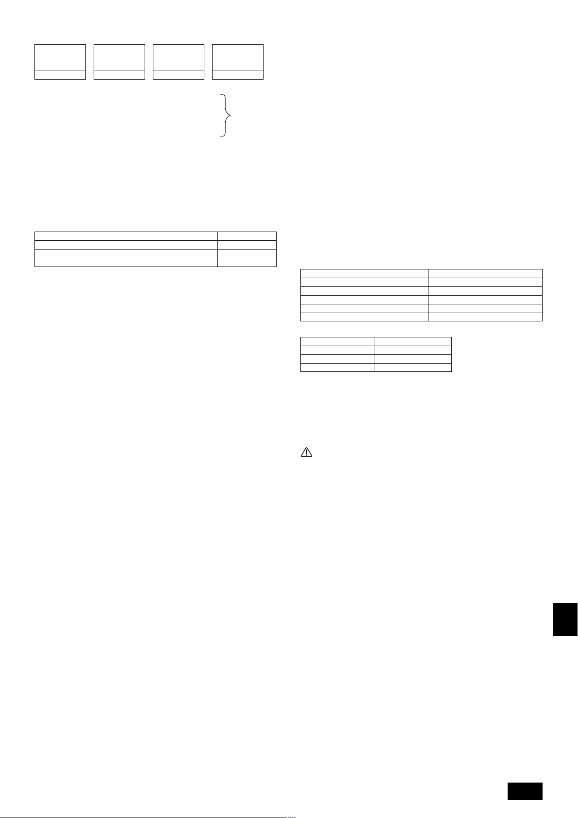
<Дополнительный заряд>
Дополнительный
заряд
хладагента
(кг)
<Пример>
Внутр. 1: 40 A: ø12,7 40 м a: ø6,35 10 м
2: 100 B: ø9,52 10 м b: ø9,52 5 м
3: 40 C: ø9,52 15 м c: ø6,35 10 м
4: 32 d: ø6,35 10 м
5: 63 e: ø9,52 10 м
Общая длина каждой линии жидкости следующая:
ø12,7: A = 40 м
ø9,52: B + b + e = 10 + 5 + 10 = 25 м
ø6,35: a + c + d = 10 + 10 + 10 = 30 м
Следовательно,
<Пример расчета>
Дополнительный заряд хладагента
= 40 × 0,12 + 25 × 0,06 + 30 × 0,024 + 2 = 9,02 кг
Значение α
Общая мощность соединяющихся внтуренних приборов α
Размер трубы
жидкости Общая
=+++ α
длина ø12,7 × 0,12
(м) × 0,12 (кг/,м)
до Модели 80 1,0 кг
Модели 81 - 160 1,5 кг
Модели 161 - 325 2,0 кг
Размер трубы
жидкости Общая
длина ø9,52 × 0,06
(м) × 0,06 (кг/м)
Размер трубы
жидкости Общая
длина ø6,35 × 0,024
(м) × 0,024 (кг/м)
При
указанных
ниже
условиях
8.2. Меры предосторожности при
подсоединении труб/управлении
клапанами
• Точно выполняйте инструкции по соединению труб и эксплуатации
клапанов.
• Труба подсоединения со стороны поступления газа собрана
изготовителем.
1 При спаивании с соединительной трубой и фланцем удалите
соединительную трубу и фланец из шарового клапана и проведите
спайку вне прибора.
2 При удалении соединительной трубы и шарового клапана удалите
пломбу, прикрепленную на задней стороне этого листа и наклейте
его на поверхность фланца шарового клапана, чтобы в него не попала
пыль.
3 Цикл охлаждения закрыт круглым сплошным уплотнением при
отгрузке, для предотвращения утечки газа между фланцами.
Поскольку в таком состоянии работа невозможна, убедитесь, что вы
заменили уплотнение другим, не сплошным уплотнением, имеющим
отверстия, закрепленным у соединения трубы.
4 При укреплении уплотнения с отверстиями сотрите пыль с
поверхности фланца и уплотнения. Нанесите на обе поверхности
уплотнения слой охлаждающего машинного масла (Масло сложного
или простого эфира или алкинбензол [небольшое количество]).
[Fig. 8.2.1] (P.3)
• После продувки и зарядки хладагентом убедитесь, что ручка полностью
в открытом положении. При работе с закрытым клапаном в цикле
охлаждения возникнет нарушение давления, что в свою очередь
повредит компрессор, четырехходовой клапан и т.д.
• Определите количество дополнительного заряда хладагента с помощью
формулы и зарядите дополнительный хладагент через сервисный порт
после того, как работа по соединению труб будет завершена.
• По окончании работы надежно закройте сервисный порт и крышку, чтобы
не было утечки газа.
[Fig. 8.2.2] (P.3)
<A> [Шаровой клапан (со стороны подачи газа)]
(На этой иллюстрации клапан показан в полностью открытом состоянии.)
<B> [Шаровой клапан (со стороны подачи жидкости)]
A Стержень клапана
[Полностью закрыт изгогтовителем, при подсоединении труб, при продувке
и при зарядке дополнительным хладагентом. Полностью открыт после
выполнения этих работ.]
B Стопор [Предотвращает поворот стержня клапана на 90° или более]
C Уплотнение (Приспособление)
[Изготовитель: Ничиасу-корпорейшн]
[Тип: Т/#1991-NF]
D Соединительная труба (Приспособление)
[Используя уплотнение надежно подсоедините эту трубу к фланцу клапана,
чтобы не было утечки газа. (Крутящий момент: 25 N·m (250 кг·см)) Смажьте
обе стороны уплотнения маслом охлаждения (Масло сложного или простого
эфира или алкинбензол [небольшое количество]).]
E Открыть (Выполняйте медленно)
F Крышка, медная
[Снимите крышку и управляйте стержнем клапана. Всегда снова закрывайте
клапан крышкой по окончании работы. (Крутящий момент крышки стержня
клапана: 25 N·m (250 кг·см) или более)]
G Сервисный порт
[Используется для продувки труб хладагента и добавления дополнительного
хладагента на объекте.
Открывайте и закрывайте этот порт с помощью двустороннего гаечного
ключа.
Всегда снова закрывайте его крышкой по окончании работы. (Крутящий
момент крышки сервисного порта: 14 N·m (140 кг·см) или более)]
H Гайка с раструбом
[(Крутящий момент: 55 N·m (550 кг·см))
Ослабляйте и закручивайте эту гайку с помощью двустороннего гаечного
ключа.
Смажьте контактную поверхность раструба маслом охлаждения (Масло
сложного или простого эфира или алкинбензол [небольшое количество]).]
I ø12,7
J ø25,4 (PU(H)Y-(P)200)
ø28,58 (PU(H)Y-(P)250)
K Прокладка труб на объекте
[Припаяйте соединительную трубу. (При спайке используйте неокисленный
припай.)]
L Плотная упаковка
M Уплотнение с отверстиями
Соответствующий крутящий момент гаечного ключа с ограничителем
крутящего момента:
Внешний диаметр медной трубы (мм) Крутящий момент (N·m) / (кг·см)
Стандарт угла закручвания:
Диаметр трубы (мм) Угол закручивания (°)
ø6,35, ø9,52 60 до 90
ø12,7, ø15,88 30 до 60
ø19,05 20 до 35
[Fig. 8.2.3] (P.3)
Примечание:
Если нет гаечного ключа с ограничителем крутящего момента,
используйте следующий метод:
При закручивании гайки с раструбом с помощью гаечного ключа вы
достигаете точки, где крутящий момент резко увеличивается. Поверните
гайку с раструбом после этой точки на угол, указанный в таблице выше.
ø6,35 14 до 18 / 140 до 180
ø9,52 35 до 42 / 350 до 420
ø12,7 50 до 57,5 / 500 до 575
ø15,88 75 до 80 / 750 до 800
ø19,05 100 до 140 / 1000 до 1400
Внимание:
• Всегда удаляйте соединительную трубу и фланец из шарового
клапана и проводите спайку вне прибора.
- При спайке соединительной трубы в установленном состоянии шаровой
клапан нагреется и вызовет повреждение или утечку газа. Также могут
быть обожжены трубы внутри прибора.
• Используйте в качестве масла охлаждения масло сложного или
простого эфира или алкинбензол (небольшое количество) для
покрытия раструбов и фланцевых соединений. (Для моделей с
хладагентом R407C)
- Масло охлаждения испортится при смешивании с большим количеством
минерального масла.
8.3. Тест на герметичность, продувка и
зарядка хладагента
1 Тест на герметичность
Выполняйте при закрытом стопорном клапане наружного прибора и
герметизируйте трубы соединения и внутренний прибор через сервисный
порт на стопорном клапане наружного прибора. (Всегда герметизируйте
с сервисных портов трубы жидкости и трубы хладагента.)
[Fig. 8.3.1] (P.3)
A Азот B К внутреннему прибору
C Анализатор системы D Рукоятка Вниз
E Рукоятка Вверх F Стопорный клапан
G Труба для жидкости H Труба для газа
I Наружный прибор J Сервисный порт
<Для моделей с хладагентом R407C>
Метод проведения теста на герметичность практически такой же, как и для
R22 моделей. Однако поскольку указанные ограничения связаны с
воздействием на масло охлаждения, всегда соблюдайте их. Кроме того, при
использовании неазеотропного хладагента (R407C, и т.д.) утечка газа
вызывает изменение химического состава смеси и неблагоприятно
сказывается на эффективности работы прибора. В связи с этим необходимо
провести тщательное испытание на герметичность.
GB
D
F
E
INL
PGR
RUTR
75
Page 18
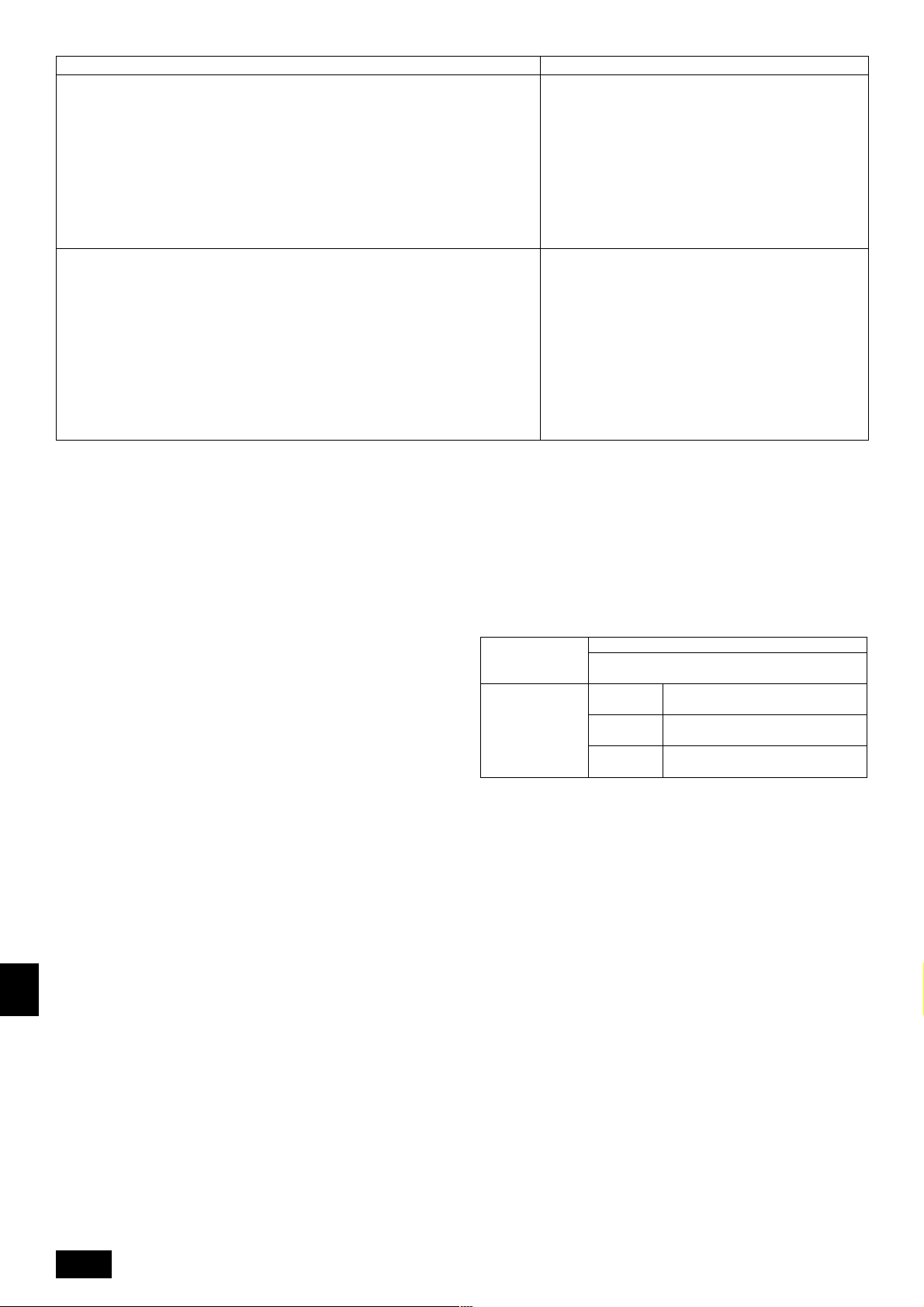
Порядок проведения теста на герметичность
1. Герметизация с помощью азота
(1) После герметизации до требуемого уровня давления (2,94 МПа) с помощью азота
оставьте прибор примерно на один день. Если после этого давление не упадет, значит
герметичность в порядке.
Однако если давление упадет, то поскольку точка утечки неизвестна, можно выполнить
следующий тест.
(2) После описанной выше герметизации опрыскайте участки соединения фланцев, участки
спайки, фланцы и другие участки, где может происходить утечка, специальным
пузырящимся агентом (Кьюбофлекс и т.д.) и затем смотрите, где будут возникать
пузырьки.
(3) После окончания теста на герметичность сотрите пузырящийся агент.
2. Герметизация с помощью газа охлаждения и азота
(1) Доведите давление газа приблизительно до 0,2 MПа, доведите до расчетного давления
(2,94 MПa), используя азот.
Однако не герметизируйте сразу. Остановитесь во время герметизации и проверьте,
что давление не падает.
(2) Проверьте, нет ли утечки через участки соединения фланцев, участки спайки, фланцы
и другие участки, где может происходить утечка, с помощью совместимого с R407C
электродетектора утечек.
(3) Этот тест можно проводить вместе с тестом с применением пузырящегося агента.
GB
Ограничения
• При использовании воспламеняющегося газа или воздуха
(кислорода) в качестве агента герметизации, может
возникнуть пожар или взрыв.
• Не используйте другие хладагенты, кроме того, который
указан на приборе.
• Герметизация газом из баллона вызовет изменение
композиционного состава хладагента в баллоне. (Для
моделей с хладагентом R407C)
• Используйте манометр давления, зарядную коробку и другие
части, специально предназначенные для R407C. (Для
моделей с хладагентом R407C)
• Электрический детектор утечки газа для хладагента R22
не способен обнаружить утечку газа хладагента R407C.
• Не используйте галлоидный фонарь. (Он не обнаружит
утечек.)
2 Продувка
D
Произведите откачку с закрытым шаровым клапаном наружного блока
кондиционера; с помощью вакуумного насоса произведите откачку как
соединительных труб, так и внутреннего блока кондиционера с сервисного
порта, расположенного на шаровом клапане наружного блока
кондиционера. (Всегда продувайте через сервисный порт трубу для
жидкости и трубу для газа.) По достижении уровня вакуума 650 Пa [abs]
F
продолжайте продувку еще в течение одного часа или более.
* Никогда не осуществляйте продувку с помощью хладагента.
[Fig. 8.3.2] (P.3)
E
INL
PGR
RUTR
A Анализатор системы B Рукоятка Вниз
C Рукоятка Вверх D Шаровой клапан
E Труба для жидкости F Труба для газа
G Сервисный порт H Тройное соединение
I Клапан J Клапан
K Баллон L Весы
M Вакуммный насос
Примечание:
• Всегда добавляйте соответствующее количество хладагента. Также
всегда герметизируйте систему жидким хладагентом. Недостаточное
или избыточное количество хладагента приведет к неполадкам.
• Используйте калиброванный манифольд, шланг зарядки и другие
части, предназначенные для хладагента, которые обозначены на
приборе.
• Используйте гравиметрический датчик. (Способный к замерам до
0,1 кг.)
• Используйте вакуумный насос с контрольным клапаном обратного
хода. (Для моделей с хладагентом R407C)
(Рекомендуемый вакуумный датчик: РОБИНЭЙР 14830А, Термистор)
Также используйте вакуумный датчик, который регистрирует 0,5 Торр
или выше после пяти месяцев работы.
3 Зарядка хладагента (Для моделей с хладагентом R407C)
Поскольку в приборе используется неазеотропный хладагент, его следует
заряжать в жидкой фазе. Соответственно, при зарядке прибора
хладагентом из баллона, если в баллоне нет сифонной трубы, заряжайте
жидкий хладагент, перевернув баллон верхом вниз, как показано ниже.
Если на баллоне нет сифонной трубы, как показано на рисунке справа,
то жидкий хладагент можно заряжать при обычном вертикальном
положении баллона. Поэтому внимательно ознакомьтесь с техническими
условиями баллона. Если прибор требуется заряжать газовым
хладагентом, замените весь хладагент новым хладагентом. Не
используйте оставшийся в баллоне хладагент.
[Fig. 8.3.3] (P.3)
8.4. Термоизоляция труб хладагента
Обязательно изолируйте трубы хладагента, обернув отдельно трубы для
жидкости и трубы для газа в термоустойчивый полиэтилен достаточной
толщины, чтобы не было зазора в соединении между внутренним прибором
и изоляционным материалом. При недостаточной изоляции произойдет
конденсация и образование капель воды. Проявляейте особое внимание к
изоляции на потолке.
[Fig. 8.4.1] (P.4)
A Стальная проволока B Трубы
C Асфальтовая мастика или асфальт
D Термоизоляционный материал А E Наружный слой В
Термоизоляционный
материал А
Наружный слой В
Примечание:
• При использовании полиэтилена в качестве покрытия не требуется
асфальтового покрытия.
• Для электропроводов не требуется термоизоляция.
[Fig. 8.4.2] (P.4)
A Труба для жидкости B Труба для газа
C Электропровод D Лента для заканчивания
E Изолятор
[Fig. 8.4.3] (P.4)
Проникновение в стены и перекрытия
[Fig. 8.4.4] (P.4)
<A> Внутренняя стена (скрытое) <B> Наружная стена
<C> Наружная стена (открытое) <D> Пол (пожарозащитное)
<E> Желоб труб на крыше
<F> Проникающая часть на пожарозащитном перекрытии и ограничивающей
стене
A Рукав B Термоизоляционный материал
C Обертывающий материал D Негорючий стройматериал
E Лента F Водонепроницаемый слой
G Рукав с кромкой H Обертывающий материал
I Бетон или другой негорючий стройматериал
J Негорючий термоизоляционный материал
При заполнении пространства бетоном закройте проникающую часть
стальной пластиной так, чтобы изоляционный материал не попадал туда.
Используйте в этом месте негорючие материалы и для изоляции, и для
покрытия. (Виниловое покрытие нельзя использовать.)
Стекловолокно + Стальная проволока
Адгезив + Термоустойчивая полиэтиленовая губка
+ Адгезивная лента
Внутренний
прибор
Пол
Наружный
прибор
Виниловая лента
Водонепроницаемая ткань +
Бронзовый асфальт
Водонепроницаемая ткань + Цинковая
пластина + Маяляная краска
76
Page 19

9. Электропроводка
9.1. Осторожно
1 Cледуйте правилам техники безопасности, официально предписанным
для работы с электрооборудованием, электропроводки и требованиям
организации по электроснабжению.
2 Проводка для управления (называемая ниже “линией передачи”) должна
отстоять на 5 см или более от проводки источника питания с тем, чтобы
на нее не влиял электрический шум от проводки источника питания. (Не
вставляйте линию передачи и кабель источника питания в один и тот же
кабелепровод.)
3 Обеспечьте правильное заземление внешнего прибора.
4 Примите во внимание проводку коробки электродеталей внутреннего и
внешнего приборов, поскольку коробку иногда приходится снимать во
время работ по техобслуживанию.
5 Никогда не подсоединяйте сетевой источник питания к колодке
концевиков линиии передачи. В противном случае произойдет подгорание
электрических элементов.
6 Используйте 2-жильный экранированный кабель для линии передачи.
Если линии передачи различных систем включаются в один и тот же
многожильный кабель, это поведет к ухудшению приема и передачи и
неустойчивой работе.
7 Только специально обозначенная линия передачи может быть
подсоединена к блоку концевиков для передачи к внешнему прибору.
(Линия передачи, подсоединяемая к внутреннему прибору: Блок
концевиков ТВ3 для линии передачи. Остальное: блок концевиков ТВ7
для централизованного управления.)
При неправильном подсоединении система не работает.
8 В случае соединения с регулятором высшего класса или для обеспечения
групповой работы различных систем хладагента необходима линия
управления для передачи между отдельными внешними приборами.
Подсоедините эту линию управления между блоками концевиков для
централизованного управления. (2-жильная линия без полярности.)
При осуществлении групповой работы в различных системах хладагента
без подсоединенного регулятора высшего класса, замените вставку
соединителя закорачивания с CN41 одного внешнего прибора на CN40.
9 Группа устанавливается при помощи дистанционного управления.
9.2. Блок управления и положение
проводки
1. Соедините линию передачи внутреннего прибора с концевыми
соединениями (ТВ3) или соедините провода между наружными приборами
или провода центральной системы управления с концевыми
соединениями центрального управления (ТВ7).
При использовании экранированного провода подсоедните
экранированный провод заземления линии передачи внутреннего
прибора к винту заземления (
заземления линии между наружным прибором и линией передачи
центральной системой управления с экранированным (S) терминалом
коробки концевых соединений (TB7) центрального управления (S). Кроме
того, при замене в наружном приборе соединителя питания CN41 на
соединитель CN40, экранированную клемму (S) коробки концевых
соединений (ТВ7) центрального управления следует также подсоединить
к заземлению (
[Fig. 9.2.1] (P.4)
A Источник питания B Линия передачи
2. Пластины монтажа кабельного желоба поставлены в комплекте (ø27).
Проведите сетевые кабели и провода передачи через соответствующие
пробиваемые отверстия, а затем снимите пробиваемую пластину с
нижней панели коробки концевых соединений и подсоедините провода.
3. Закрепите провода источника питания на коробке концевых соединений
с помощью буферной втулки для прочности на разрыв (соединитель PG
или тому подобный).
).
) и соедините экранированный провод
9.3. Прокладка кабелей передачи
1 Типы кабелей управления
1. Прокладка кабелей передачи
• Типы кабелей управления: Экранированные провода CVVS или CPEVS
• Диаметр кабеля: Свыше 1,25 мм
• Максимальная длина проводки: В пределах 200 м
2. Кабели дистанционного управления
Тип кабеля дистанционного
управления
Диаметр кабеля
Замечания
2 Примеры проводки
• Название регулятора, его символ и допускаемое число регуляторов
Название
Регулятор внешнего
прибора
Регулятор внутренних
приборов
Дистанционный блок
управления
2
2-жильный кабель (неэкранированный)
0,3 - 1,25 м
При превышении длины 10 м используйте
кабель с теми же спецификациями, какие
указаны в пункте (1) Прокладка кабелей
передачи.
Символ
OC
RC
2
Допускаемое число регуляторов
IC
2-10 регуляторов на один ОС
Максимум два на группу
GB
D
F
E
INL
Пример работы заземленной системы с многочисленными внешними приборами (подсоединения и
провода прикреплены как необходимо)
<Примеры проводки кабелей передачи>
[Fig. 9.3.1] Контроллер ДУ “M-NET” (P.4)
[Fig. 9.3.2] Контроллер ДУ “MA” (P.4)
A Группа 1 B Группа 3 C Группа 5 D Экранированный провод E Дополнительный дистанционный блок управления
( ) Адрес
<Метод электропроводки и адресная настройка>
a. Всегда используйте экранированные провода при соединении между внешним прибором (ОС) и внутренним прибором (IC), а также между ОС и ОС и IC и IC.
b. Используйте фидерную проводку для соединения концевиков M1 и M2 и концевика заземления на блоке кабеля передачи (ТВ3) каждого внешнего прибора
(ОС) с концевиками M1, M2 и S на блоке кабеля передачи внутреннего прибора (IC).
c. Соедините концевики 1 (M1) и 2 (M2) на блоке концевиков кабеля передачи внутреннего прибора (IC), который имеет самый недавний адрес в этой же
группе, к блоку концевиков на дистанционном блоке управления (RC).
d. Соедините между собой концевики M1, M2 и S на блоке концевиков для центрального регулятора (ТВ7) для обоих внешних приборов (ОС).
e. Только на одном внешнем приборе - измените соединительную перемычку на панели управления с CN41 на CN40.
f. Соедините концевик S на блоке концевиков центрального регулятора (ТВ7) внешнего прибора (ОС) для того прибора, в который была вставлена
соединительная перемычка CN40, к концевику заземления
g. Установите выключатель адресной настройки, как показано ниже.
* Чтобы установить адрес наружного прибора на 100, переключатель адреса наружного прибора должен быть установлен на 50.
в коробке электрической панели.
PGR
RUTR
77
Page 20

Прибор Диапазон Метод настройки
IC (Главный) 01 - 50 Используйте самый недавний адрес в одной и той же группе внутренних приборов (IC)
IC (Дополнительный) 01 - 50
Внешний прибор 51 - 100 Используйте самый недавний адрес из всех внутренних приборов в той же системе хладагента + 50
M-NET R/C (Главный) 101 - 150 Настройте адрес IC (Главного) + 100
M-NET R/C (Дополнительный)
h. Операция групповой настройки среди некоторого числа внутренних приборов выполняется дистанционным блоком управления (RC) после включения
<Допускаемая длина>
1 Контроллер ДУ “M-NET”
• Максимальная длина через внешние приборы: L
• Максимальная длина кабеля передачи: L
• Длина провода дистанционного блока управления:r
2 Контроллер ДУ “MA”
• Максимальная длина через внешние приборы (Кабель M-NET): L
• Максимальная длина кабеля передачи (Кабель M-NET): L
GB
• Длина провода дистанционного блока управления:c
MA R/C – Ненужная настройка адреса (Необходимая настройка - установка “главный/подчиненный”)
электропитания. Более подробная информация приводится в руководстве по установке дистанционного регулятора.
151 - 200 Настройте адрес IC (Главного) + 150
Используйте адрес, помимо адреса IC (Главного) из приборов в одной и той же группе внутренних приборов. Он
должен быть последовательным с IC (Главным)
1+L2+L3+L4 и L1+L2+L3+L5 и L1+L2+L6+L7
1 и L3+L4 и L3+L5 и L6 и L2+L6 и L7
1, r2, r3, r4
Если длина превышает 10 м, используйте экранированный провод 1,25 мм
должна быть включена в расчет максимальной длины и общей длины.
1 и L3+L4 и L6 и L2+L6 и L7
1+c2 и c1+c2+c3+c4
10 м (0,3 - 1,25 мм2)
=
1+L2+L3+L4 и L1+L2+L6+L7
200 м (Не менее 1,25 мм2)
=
200 м (0,3 - 1,25 мм2)
=
500 м (Не менее 1,25 мм2)
=
500 м (Не менее 1,25 мм2)
=
200 м (Не менее 1,25 мм2)
=
2
. Длина этого отрезка (L8)
9.4. Электропроводка для сетевого питания и характеристики оборудования
Схема электропроводки (Пример)
D
[Fig. 9.4.1] (P.4)
A Выключатель (прерывание цепи и утечки тока) B Внешний прибор
C Коробка пенального типа D Внутренний прибор
Толщина проводов для главного источника питания и характеристики вкл/выкл.
F
Mодель
Внешний
прибор
Внутренний прибор
E
1. Используйте отдельный источник питания для подключения наружного и внутреннего приборов.
2. При проведении проводки и электросоединений имейте в виду окружающие условия (температуру окружающего воздуха, прямые солнечные
лучи, дождевую воду и т. д.).
3. Размер провода является минимальной величиной для электропроводки в металлических трубах. Размер кабеля питания должен быть на 1
порядок толще ввиду падений напряжения. Убедитесь в том, что напряжение в сети питания падает не более, чем на 10 %.
INL
4. Необходимо следовать специфическим требованиям по проведению электропроводки, соответствующим нормативам данного региона.
5. Шнуры питания частей устройств, предназначенных для наружной эксплуатации, не должны быть легче, чем гибкий шнур с оболочкой из
полихлоропрена (дизайн 245 IEC57). К примеру, используйте проводку типа YZW.
(P)200
(P)250
Mагистр. кабель
4,0
6,0
1,5
Отвод Характ. Предохр.
–
–
1,5
Заземл.
4,0
6,0
1,5
Выключатель (А)Минимальная толщина провода (мм2)
32
40
16
32
40
16
Прерыватель
цепи (NFB)
40 A
40 A
20 A
Прерыватель против утечки тока
30 А 100 мА 0,1сек. или менее
40 A 100 мА 0,1сек. или менее
20 А 30 мА 0,1сек. или менее
Предупреждение:
• Обязательно используйте для соединений указанные провода так, чтобы на соединения концевиков не действовала внешняя сила. Ненадежные
соединения могут вызвать перегрев или пожар.
• Обязательно убедитесь в том, что Вы используете соответствующий тип переключателя защиты от сверхтока. Заметьте, что генерируемый сверхток
может включать в себя некоторое количество постоянного тока.
Внимание:
PGR
• На некоторых площадках может потребоваться установка прерывателя заземления. Отсутствие прерывателя в линии заземления может привести
к электрическому удару.
• Используйте только прерыватели и предохранители с правильной характеристикой. Применение предохранителя или медного провода со слишком
высокой характеристикой может вызвать отказ или возгорание прибора.
RUTR
78
Page 21

10. Контрольный запуск
10.1. Указанные ниже явления не являются неисправностями
Явление
Внутренний прибор не выполняет
охлаждения (отопления)
Автовентилятор работает в свободном
режиме
При отоплении изменяется настройка
вентилятора
Во время отапливания вентилятор
останавливается
Вентилятор не останавливается после
окончания работы прибора
Вентилятор не настраивается после
включения выключателя.
При включении выключателя не
включается наружный прибор
Дистанционное управление внутреннего
прибора показывает индикацию “НО”
примерно в течение двух минут после
включения электропитания.
Дренажный насос не останавливается
после остановки прибора
Дренажный насос продолжает работать
после остановки прибора
Дисплей на пульте дистанционного
управления
Мигает “Охлаждение (отопление)”
Дисплей обычный
Дисплей обычный
Дисплей размораживания
Нет света
Отопление готово к работе
Дисплей обычный
Мигает “НО”
Свет не горит
Причина
Когда другой внутренний прибор выполняет охлаждение (отопление),
отопление (охлаждение) не выполняется.
В связи с режимом управления автовентилятора он может изменять
автоматически направление выдува на горизонтальное с выдува вниз при
охлаждении, если выдув вниз выполнялся в течение 1 часа. Во время
размораживания в режиме отопления при выключенном термостате он
автоматически меняет направление выдува на горизонтальное.
Операция на ультра-низкой скорости начинается при выключенном
термостате.
Легкий воздух автоматически настраивается на установленное значение
по времени или на температуру в трубопроводе при включенном термостате.
При размораживании вентилятор должен останавливаться
Вентилятор будет работать примерно 1 час после остановки для выдува
остаточного тепла (только при отоплении)
Работа на ультра-низкой скорости в течение 5 минут после включения
выключателя или до тех пор, пока температура трубопровода не достигнет
35 °С; работа на низкой скорости ещё в течение 2-х минут после этого и
затем в установленной скорости. (Управление температурой.)
При охлаждении наружного прибора и отдыхе хладагента нагревание
выполняется в течение не менее 35 минут для прогревания компрессора.
В это время работает только вентилятор.
Система приводится в действие приводом.
Снова включите дистанционный контроллер после того, как “НО” исчезнет.
После прекращения охлаждения дренажный насос прибора продолжает
работать в течение трёх минут и затем останавливается.
Прибор продолжает работу дренажого насоса, если генерируется жидкость
для дренажа, даже во время остановки.
GB
D
F
E
INL
PGR
RUTR
79
Page 22

This product is designed and intended for use in the residential, commer-
cial and light-industrial environment.
The product at hand is
based on the following
EU regulations:
• Low Voltage Directive 73/23/EEC
• Electromagnetic Compatibility Directive 89/
336/EEC
Please be sure to put the contact address/telephone number on
this manual before handing it to the customer.
WT03195X02
HEAD OFFICE MITSUBISHI DENKI BLDG MARUNOUCHI TOKYO 100-8310 TELEX J24532 CABLE MELCO TOKYO
Printed in Japan
 Loading...