

Page 1

Air-Conditioners
geprgeprüftefte
SicherheitSicherheit
OUTDOOR UNIT
PUHY-P-YMF-B
FOR INSTALLER
FÜR INSTALLATEURE
POUR L’INSTALLATEUR
VOOR DE INSTALLATEUR
PER L’INSTALLAT ORE
INSTALLATION MANU AL
For safe and correct use, please read this installation manual thoroughly before installing the air-conditioner unit.
∗ Remote controller (PAR-F25MA) is available as an optional remote controller.
INSTALLATIONSHANDBUCH
Zum sicheren und ordnungsgemäßen Gebrauch der Klimageräte das Installationshandbuch gründlich durchlesen.
∗ Fernbedienung (PAR-F25MA) ist als Zubehör wahlweise erhältlich.
ENGLISH
DEUTSCH
FRANÇAIS
MANUEL D’INSTALLATION
Veuillez lire le manuel d’installation en entier avant d’installer ce climatiseur pour éviter tout accident et vous assurer d’une utilisation
correcte.
∗ La télécommande (PAR-F25MA) est disponible en option.
INSTALLATIEHANDLEIDING
Voor een veilig en juist gebruik moet u deze installatiehandleiding grondig doorlezen voordat u de airconditioner installeert.
∗ De afstandsbedieningseenheid (PAR-F25MA) is verkrijgbaar als een optioneel toe te voegen afstandsbediening.
MANUALE DI INSTALLAZIONE
Per un uso sicuro e corretto, leggere attentamente questo manuale di installazione prima di installare il condizionatore d’aria.
∗ Il comando a distanza (modello PAR-F25MA) disponibile in opzione.
NEDERLANDS
ITALIANO
Page 2

Contents
1. Safety precautions ...................................................................... 3
1.1. Before installation and electric work ............................... 3
1.2. Precautions for devices that use R407C refrigerant.......3
1.3. Before getting installed ................................................... 4
1.4. Before getting installed (moved) - electrical work ........... 4
1.5. Before starting the test run ............................................. 4
2. Combination with indoor units..................................................... 5
3. Confirmation of parts attached ................................................... 5
4. Combination with outdoor units ................................................... 6
5. Selection of installation site ........................................................ 6
6. Space required around unit ........................................................ 6
6.1. Individual installation ...................................................... 6
6.2. Collective installation and continuous installation........... 7
7. Lifting method and weight of product.......................................... 8
8. Installation of unit........................................................................ 8
8.1. Location of anchor bolt ................................................... 8
8.2. Installation ...................................................................... 9
8.3. Connecting direction for refrigerant piping.................... 10
ENGLISH
8.4. Noise level .................................................................... 10
9. Caution for snow and seasonal wind ........................................ 11
9.1. Snow and seasonal wind.............................................. 11
9.2. Countermeasure to seasonal wind ............................... 11
10. Refrigerant piping installation.................................................. 11
10.1. Areas of caution .......................................................... 12
10.2. Refrigerant piping system ........................................... 13
10.3. Caution for piping connection/valve operation ............ 15
10.4. How to install branch pipe ........................................... 16
10.5. Airtight test and evacuation, refrigerant charging........ 18
10.6. Thermal insulation of refrigerant piping....................... 21
11. Electrical work ......................................................................... 23
11.1. Caution........................................................................ 23
11.2. Control box and connecting position of wiring............. 24
11.3. Wiring transmission cables ......................................... 25
11.4. Wiring of main power supply and equipment
capacity ....................................................................... 31
12. Test run.................................................................................... 32
12.1. Checking before getting test run ................................. 32
12.2. Test run method .......................................................... 32
12.3. How to cope with test run abnormality ........................ 33
12.4. Coping with remote controller abnormality.................. 35
12.5. The following phenomena do not represent
abnormality (emergency) ............................................ 36
2
Page 3
1. Safety precautions
1.1. Before installation and electric work
s Before installing the unit, make sure you read all the
“Safety precautions”.
s The “Safety precautions” provide very important
points regarding safety. Make sure you follow them.
s This equipment may not be applicable to EN61000-3-
2: 1995 and EN61000-3-3: 1995.
s This equipment may cause the adverse effect on the
same supply system.
s Please report to or take consent by the supply author-
ity before connection to the system.
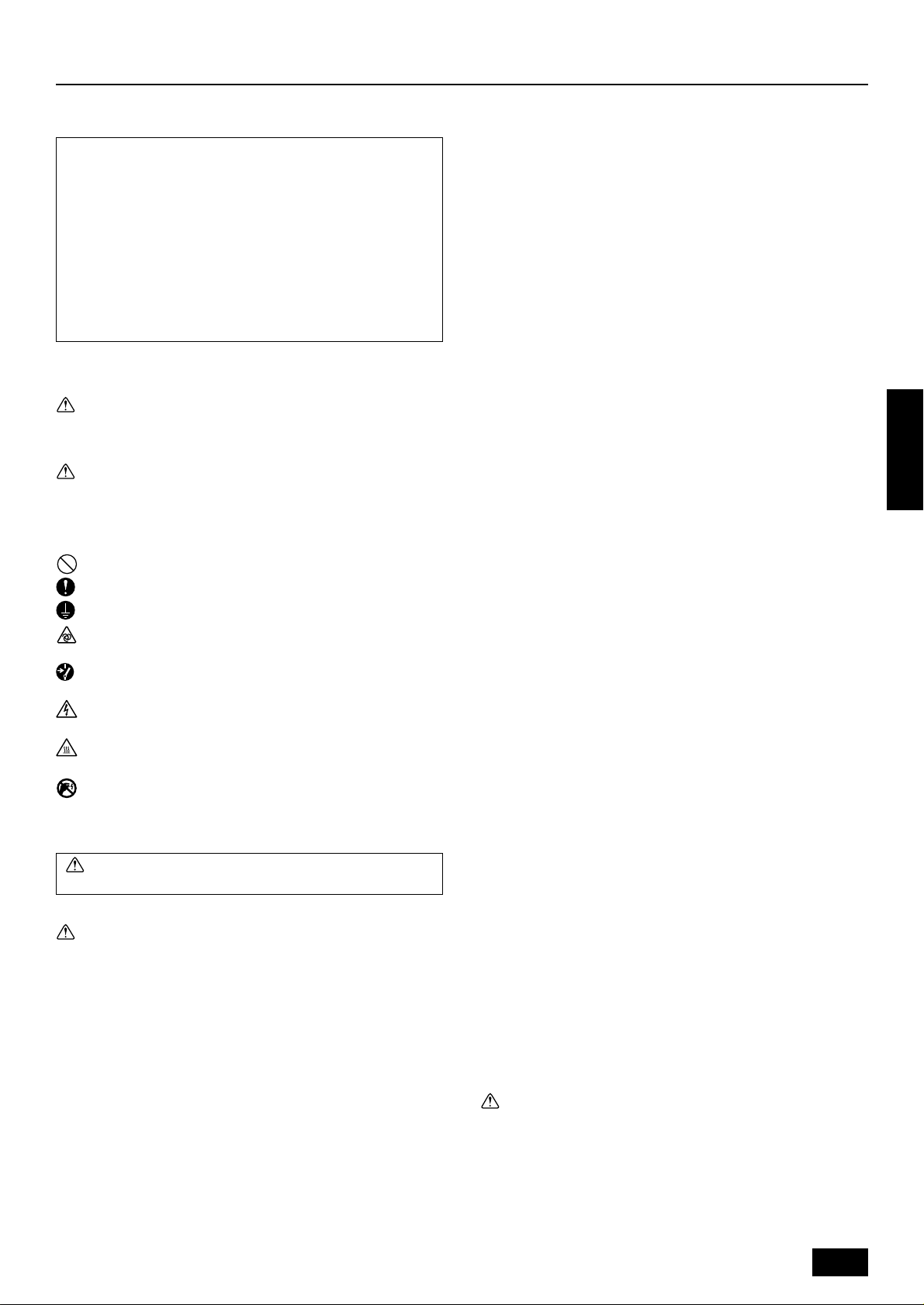
Symbols used in the text
Warning:
Describes precautions that should be observed to prevent danger
of injury or death to the user.
Caution:
Describes precautions that should be observed to prevent damage
to the unit.
Symbols used in the illustrations
: Indicates an action that must be avoided.
: Indicates that important instructions must be followed.
: Indicates a part which must be grounded.
: Indicates that caution should be taken with rotating parts. (This
symbol is displayed on the main unit label.) <Color: Yellow>
: Indicates that the main switch must be turned off before servicing.
(This symbol is displayed on the main unit label.) <Color: Blue>
: Beware of electric shock. (This symbol is displayed on the main
unit label.) <Color: Yellow>
: Beware of hot surface. (This symbol is displayed on the main unit
label.) <Color: Yellow>
: Please pay attention to electric shock fully because this is
ELV
not Safety Extra Low-Voltage (SELV) circuit.
And at servicing, please shut down the power supply for both
of Indoor Unit and Outdoor Unit.
Warning:
Carefully read the labels affixed to the main unit.
Warning:
• Ask the dealer or an authorized technician to install the air conditioner.
- Improper installation by the user ma y result in water leakage, elec-
tric shock, or fire.
• Install the air unit at a place that can withstand its weight.
- Inadequate strength may cause the unit to fall down, resulting in
injuries.
• Use the specified cables for wiring. Make the connections securely so that the outside force of the cable is not applied to the
terminals.
- Inadequate connection and fastening may gener ate heat and cause
a fire.
• Prepare for typhoons and other strong winds and earthquakes
and install the unit at the specified place.
- Improper installation may cause the unit to topple and result in in-
jury.
• Always use an air cleaner, humidifier, electric heater, and other
accessories specified by Mitsubishi Electric.
- Ask an authorized technician to install the accessories. Improper
installation by the user may result in water leakage, electric shock,
or fire.
• Never repair the unit. If the air conditioner must be repaired,
consult the dealer.
- If the unit is repaired improperly, water leakage, electric shock, or
fire may result.
• Do not touch the heat exchanger fins.
- Improper handling may result in injury.
• If refrigerant gas leaks during installation work, ventilate the
room.
- If the refrigerant gas comes into contact with a flame, poisonous
gases will be released.
• Install the air conditioner according to this Installation Manual.
- If the unit is installed improperly, water leakage, electric shock, or
fire may result.
• Have all electric work done by a licensed electrician according
to “Electric Facility Engineering Standard” and “Interior Wire
Regulations”and the instructions given in this manual and always use a special circuit.
- If the power source capacity is inadequate or electric work is per-
formed improperly, electric shock and fire may result.
• Securely install the outdoor unit terminal cover (panel).
- If the terminal cover (panel) is not installed properly, dust or water
may enter the outdoor unit and fire or electric shock may result.
• When installing and moving the air conditioner to another site,
do not charge the it with a refrigerant different from the refrigerant (R407C) specified on the unit.
- If a different refrigerant or air is mixed with the original refrigerant,
the refrigerant cycle may malfunction and the unit may be damaged.
• If the air conditioner is installed in a small room, measures must
be taken to prevent the refrigerant concentration from exceeding the safety limit even if the refrigerant should leak.
- Consult the dealer regarding the appropriate measures to prevent
the safety limit from being exceeded. Should the refrigerant leak
and cause the safety limit to be exceeded, hazards due to lack of
oxygen in the room could result.
• When moving and reinstalling the air conditioner, consult the
dealer or an authorized technician.
- If the air conditioner is installed improperly, water leakage, electric
shock, or fire may result.
• After completing installation work, make sure that refrigerant
gas is not leaking.
- If the refrigerant gas leaks and is exposed to a fan heater, stove,
oven, or other heat source, it may generate noxious gases.
• Do not reconstruct or change the settings of the protection devices.
- If the pressure switch, thermal switch, or other protection de vice is
shorted and operated forcibly, or parts other than those specified
by Mitsubishi Electric are used, fire or explosion may result.
• To dispose of this product, consult your dealer.
• The installer and system specialist shall secure safety against
leakage according to local regulation or standards.
- Following standards may be applicable if local regulation are not
available.
• Pay a special attention to the place, such as a basement, etc.
where refrigeration gas can stay, since refrigeration is heavier
than the air.
1.2. Precautions for devices that use
R407C refrigerant
Caution:
• Do not use the existing refrigerant piping.
- The old refrigerant and refrigerator oil in the existing piping con-
tains a large amount of chlorine which may cause the refrigerator
oil of the new unit to deteriorate.
• Use refrigerant piping made of C1220 (CU-DHP) phosphorus
deoxidized copper as specified in the JIS H3300 “Copper and
copper alloy seamless pipes and tubes”. In addition, be sure
that the inner and outer surfaces of the pipes are clean and free
ENGLISH
3
Page 4

of hazardous sulphur, oxides, dust/dirt, shaving particles, oils,
moisture, or any other contaminant.
- Contaminants on the inside of the refrigerant piping may cause the
refrigerant residual oil to deteriorate.
• Store the piping to be used during installation indoors and keep
both ends of the piping sealed until just before brazing. (Store
elbows and other joints in a plastic bag.)
- If dust, dirt, or water enters the refrigerant cycle, deterioration of
the oil and compressor trouble may result.
• Use ester oil, ether oil or alkylbenzene (small amount) as the
refrigerator oil to coat flares and flange connections.
- The refrigerator oil will degrade if it is mixed with a large amount of
mineral oil.
• Use liquid refrigerant to fill the system.
- If gas refrigerant is used to seal the system, the composition of the
refrigerant in the cylinder will change and performance may drop.
• Do not use a refrigerant other than R407C.
- If another refrigerant (R22, etc.) is used, the chlorine in the refriger-
ant may cause the refrigerator oil to deteriorate.
• Use a vacuum pump with a reverse flow check valve.
- The vacuum pump oil may flow back into the refrigerant cycle and
cause the refrigerator oil to deteriorate.
• Do not use the following tools that are used with conventional
refrigerants.
(Gauge manifold, charge hose, gas leak detector, reverse flow
check valve, refrigerant charge base, vacuum gauge, refrigerant recovery equipment)
- If the conventional refrigerant and refrigerator oil are mixed in the
ENGLISH
R407C, the refrigerant may deteriorated.
- If water is mixed in the R407C, the refrigerator oil may deteriorate.
- Since R407C does not contain any chlorine, gas leak detectors for
conventional refrigerants will not react to it.
• Do not use a charging cylinder.
- Using a charging cylinder may cause the refrigerant to deteriorate.
• Be especially careful when managing the tools.
- If dust, dirt, or water gets in the refrigerant cycle, the refrigerant
may deteriorate.
1.3. Before getting installed
Caution:
• Do not install the unit where combustible gas may leak.
- If the gas leaks and accumulates around the unit, an explosion
may result.
• Do not use the air conditioner where food, pets, plants, precision instruments, or artwork are kept.
- The quality of the food, etc. may deteriorate.
• Do not use the air conditioner in special environments.
- Oil, steam, sulfuric smoke, etc. can significantly reduce the per-
formance of the air conditioner or damage its parts.
• When installing the unit in a hospital, communication station,
or similar place, provide sufficient protection against noise.
- The inverter equipment, private power generator, high-frequency
medical equipment, or radio communication equipment may cause
the air conditioner to operate erroneously , or f ail to operate. On the
other hand, the air conditioner may affect such equipment by creating noise that disturbs medical treatment or image broadcasting.
• Do not install the unit on a structure that may cause leakage.
- When the room humidity exceeds 80% or when the drain pipe is
clogged, condensation may drip from the indoor unit. Perform collective drainage work together with the outdoor unit, as required.
1.4. Before getting installed (moved) -
electrical work
Caution:
• Ground the unit.
- Do not connect the ground wire to gas or water pipes, lightning
rods, or telephone ground lines. Improper grounding may result in
electric shock.
• The reverse phase of L lines (L
cord : 4103), but the reverse phase of L lines and N line can be
not be detected.
- The some electric parts should be damaged when power is sup-
plied under the miss wiring.
• Install the power cable so that tension is not applied to the cable.
- Tension may cause the cable to break and generate heat and cause
a fire.
• Install an leak circuit breaker, as required.
- If an leak circuit breaker is not installed, electric shock may result.
• Use power line cables of sufficient current carrying capacity
and rating.
- Cables that are too small may leak, generate heat, and cause a
fire.
• Use only a circuit breaker and fuse of the specified capacity.
- A fuse or circuit breaker of a larger capacity or a steel or copper
wire may result in a general unit failure or fire.
• Do not wash the air conditioner units.
- Washing them may cause an electric shock.
• Be careful that the installation base is not damaged by long use.
- If the damage is left uncorrected, the unit may fall and cause per-
sonal injury or property damage.
• Install the drain piping according to this Installation Manual to
ensure proper drainage. Wrap thermal insulation around the
pipes to prevent condensation.
- Improper drain piping may cause water leakage and damage to
furniture and other possessions.
• Be very careful about product transportation.
- Only one person should not carry the product if it weighs more than
20 kg.
- Some products use PP bands for packaging. Do not use any PP
bands for a means of transportation. It is dangerous.
- Do not touch the heat exchanger fins. Doing so may cut your fin-
gers.
- When transporting the outdoor unit, suspend it at the specified po-
sitions on the unit base. Also support the outdoor unit at four points
so that it cannot slip sideways.
• Safely dispose of the packing materials.
- Packing materials, such as nails and other metal or wooden parts,
may cause stabs or other injuries.
- Tear apart and throw a way plastic packaging bags so that children
will not play with them. If children pla y with a plastic bag which was
not torn apart, they face the risk of suffocation.
1, L2, L3) can be detected (Error
1.5. Before starting the test run
Caution:
• Turn on the power at least 12 hours before starting operation.
- Starting operation immediately after turning on the main power
switch can result in severe damage to internal parts. Keep the pow er
switch turned on during the operational season.
• Do not touch the switches with wet fingers.
- Touching a switch with wet fingers can cause electric shock.
• Do not touch the refrigerant pipes during and immediately after
operation.
- During and immediately after operation, the refrigerant pipes are
may be hot and may be cold, depending on the condition of the
refrigerant flowing through the refrigerant piping, compressor, and
other refrigerant cycle parts. Your hands may suffer burns or frostbite if you touch the refrigerant pipes.
• Do not operate the air conditioner with the panels and guards
removed.
- Rotating, hot, or high-voltage parts can cause injuries.
• Do not turn off the power immediately after stopping operation.
- Alwa ys wait at least five minutes before turning off the power. Oth-
erwise, water leakage and trouble may occur.
4
Page 5
2. Combination with indoor units
The indoor units connectable to this unit are shown below.
Outdoor unit model
name
Note:
1. The total capacity of connected indoor unit models represents the total sum of the figures expressed in the indoor model name.
2. Combinations in which the total capacity of the connected indoor units exceeds the capacity of the outdoor unit will reduce the capacity
of each indoor unit below the rated capacity during simultaneous operation. Therefore, if circumstances allows, combine indoor units
within the capacity of the outdoor unit.
3. A transmission booster (RP) is required when the number of connected indoor unit models in a cooling system exceeds the number of
models specified in the chart below.
* The maximum number of units that can be controlled is determined by the indoor unit model, the type of remote controller and their
capabilities.
(*1)
Capability of the
connected indoor units
*1 If even one unit that is higher than 200 exists in the cooling system, the maximum capacity will be “200 or higher”.
Total capacity of
connected indoor unit
models
200 to 520PUHY-P400
250 to 650PUHY-P500
Number of connected indoor units that can be
connected without a RP.
200 or lower
200 or higher
Quantity of connectable
indoor unit
PMFY-P25 · 32 · 40 · 63 VBM
PLFY- P32· 40 · 50 · 63 · 80 · 100 · 125 VKM
PLFY- P25· 32 · 40 · 50 · 63 · 80 · 100 · 125 VLMD
PEFY-P25 · 32 VML
2 to 20
Remote controller type
The number of indoor units and the total number of remote controllers is displayed within the parenthesis ( ).
PEFY-P40 · 50 · 63 · 71 · 80 · 100 · 125 · 140 · 200 · 250 VMH
PCFY-P40· 63 · 100 · 125 VGM
PKFY-P25 VAM
PKFY-P32 · 40 · 50 VGM
PFFY- P25 · 32 · 40 · 50 · 63 VLEM
PFFY- P25 · 32 · 40 · 50 · 63 VLRM
PDFY-P25· 32 · 40 · 50 · 63 · 71 · 80 · 100 · 125 VM
Model name of connectable indoor unit
Remote controller PAR-F 25MA
Prior to Ver. E After Ver. F
16 (32) 20 (40)
16 (32) 16 (32)
ENGLISH
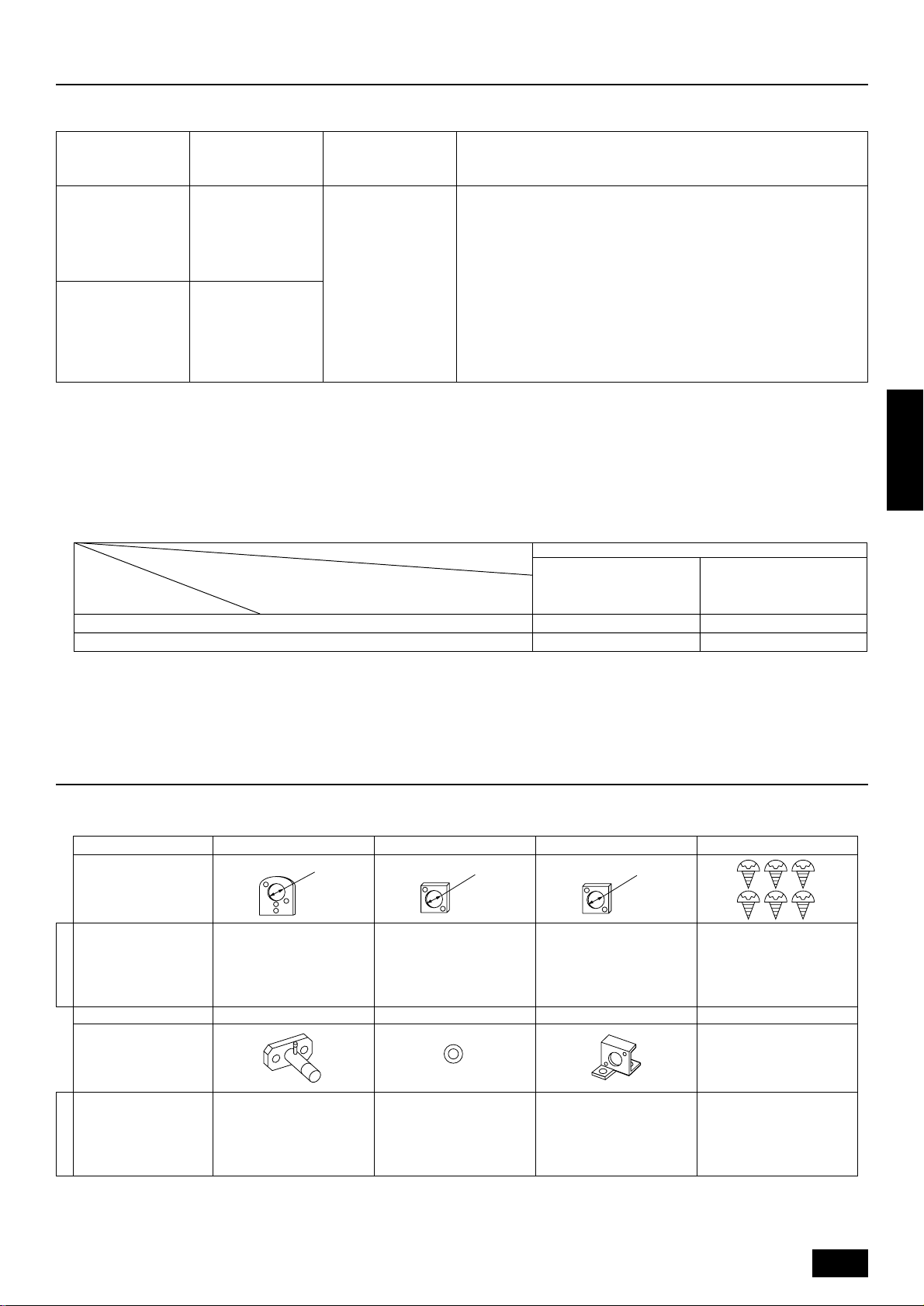
3. Confirmation of parts attached
This outdoor unit is attached with the parts below. Please check the quantity for each item.
Name 1 Conduit mounting plate 2 Conduit mounting plate 3 Conduit mounting plate 4 Tapping screw M4 × 10
PUHY-P400
PUHY-P500
Model name
PUHY-P400
PUHY-P500
Model name
ø62
Shape
1116
Name 5 Connecting pipe 6 Packing 7 Wire mounting plate
Shape
inside ø29, outside ø39
111
ø53
ø46
*5 Connecting pipe is fixed with the unit.
5
Page 6
C
C
D
A
A
B
Hh
B
4. Combination with outdoor units
A Super Y (PUHY-P600/650/700/750YSMF-B) is produced when a Constant Capacity Unit (PUHN-P200/250YMF-B) is combined with this unit (PUHYP400/500YMF-B).
Refer to the installation manual that comes with the Constant Capacity Unit when this unit is used as a Super Y.
Super Y
PUHY-P600YSMF-B
PUHY-P650YSMF-B
PUHY-P700YSMF-B
PUHY-P750YSMF-B
Variable capacity unit
PUHY-P400YMF-B
PUHY-P500YMF-B
Constant capacity unit
PUHN-P200YMF-B
PUHN-P250YMF-B
PUHN-P200YMF-B
PUHN-P250YMF-B
5. Selection of installation site
Select space for installing outdoor unit, which will meet the following
conditions:
• no direct thermal radiation from other heat sources
• no possibility of annoying neighbors by noise from unit
• no exposition to strong wind
• with strength which bears weight of unit
• note that drain flows out of unit when heating
• with space for air passage and service work shown below
Because of the possibility of fire, do not install unit to the space where
ENGLISH
generation, inflow, stagnation, and leak of combustible gas is expected.
• Avoid unit installation in a place where acidic solution and spra y (sulfur)
are often used.
• When having cooling operation at an outside air temperature of below 10°C, in order to obtain steady operation of unit, select an installation site not exposed directly to rain and snow, or install air outlet
and inlet ducts. (Refer to Page 11.) Install the outdoor unit at the
same position on the same floor, or above, the indoor unit. (See the
figure at the right.)
• Do not use unit in any special environment where oil, steam and
sulfuric gas exist.
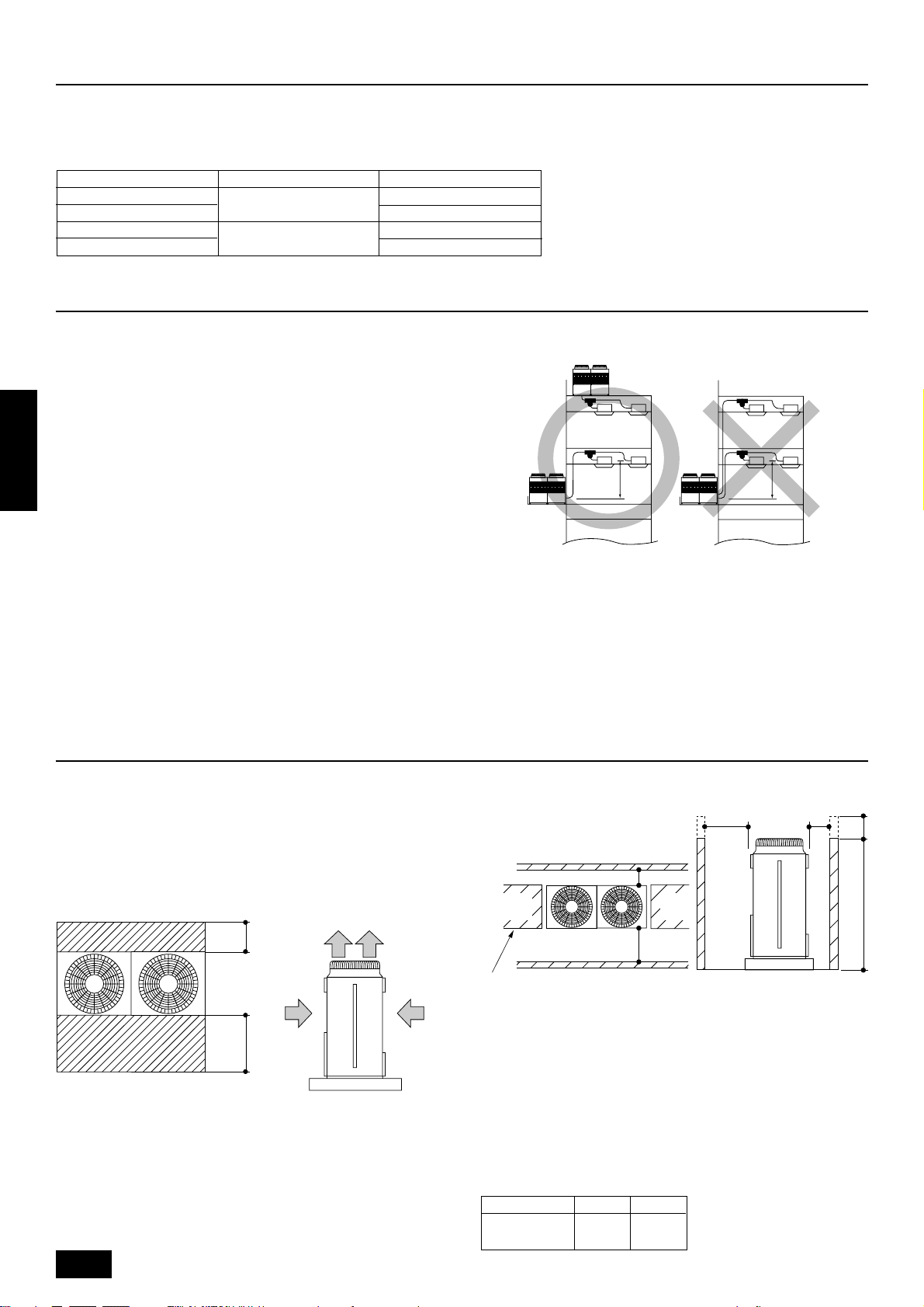
6. Space required around unit
Installation restriction on outdoor unit when cooling operation is performed
when the outdoor air temperature is 10°C or lower
A
(Same floor as indoor unit, or floor above)
A 4 m or less
6.1. Individual installation
Basic space required
A space of at least 250 mm is necessary at the back for inlet air. Taking
servicing, etc. from the rear into account, a space of about 450 mm
should be provided, the same as at the front.
D
A
FE
B
C
<Top view> <Side view>
A 250 mm or more
B 450 mm or more
C Front (outside of machine room)
D Top discharge (open in principle)
E Front inlet (open in principle)
F Rear inlet (open in principle)
6
When inlet air enters from right and left sides of unit
<Side view>
A L1 or more
B L
2 or more
C Front
D No restrictions on wall height (left and right)
Note:
• Wall heights (H) of the front and the back sides shall be within
overall height of unit.
• When the total height is exceeded, add the “h” dimension of the
figure above to L1 and L2 in the table above.
Model L1 L2
PUHY-P400
PUHY-P500
450 250
Page 7
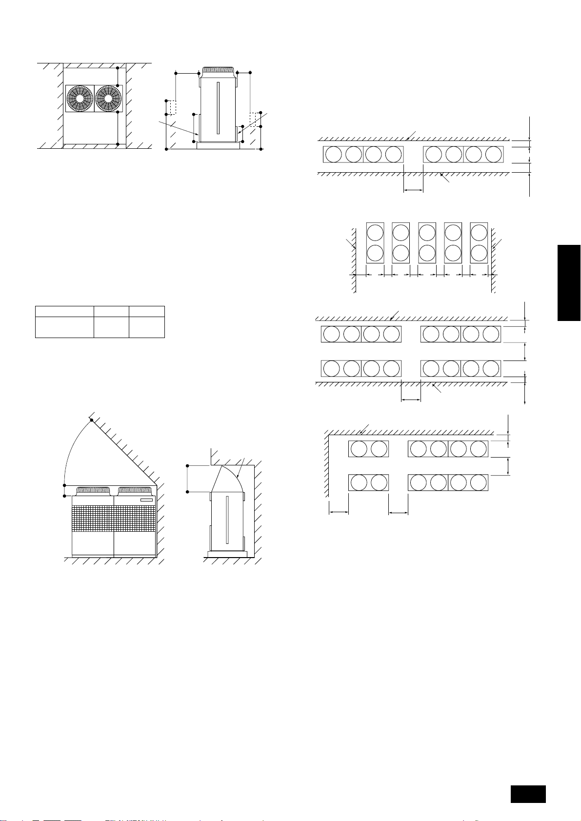
When unit is surrounded by walls
B
A
D
A
C
650
Hh
B
325
E
h
H
6.2. Collective installation and continuous installation
Space required for collective installation and continuous installation:
When installing several units, leave the space between each block as
shown below considering passage for air and people.
B
*E
C
<Side view>
A L
1 or more
2 or more
B L
C Front
D Front panel
E Rear panel
Note:
• Wall heights (H) of the front and the back sides shall be within
height of front panel and rear panel.
• If the panel height is exceeded, add the “h” dimension of the
figure above to L1 and L2 in the table above.
Model L1 L2
PUHY-P400
PUHY-P500
Example: When h is 100
The L1 dimension becomes 450+100=550 mm.
When there is an obstruction above the unit
450 250
AA
CC
D
B
*F
A
B
CCCCC
*FF F F F*E
B
A
ENGLISH
A
B
B
D
B
E
E
GCC
E
A
A
B
A 45° or more
B 300 mm or more
C Front
D 1000 mm or more
E Air outlet guide (Procured at the site)
F Rear
E
D
CF
When there is little space
up to an obstruction
A
C
DD
A
A (Must be open)
B Wall height (H)
C Front
D 1000 mm or more
E 250 mm or more
F 450 mm or more
G 900 mm or more
Note:
• Open in the two directions.
• In case wall height (H) exceeds overall height of unit, add “h”
dimension (h=wall height <H> – overall height of unit) to * marked
dimension.
• If there is a wall at both the front and the rear of the unit, install
up to three units consecutively in the side direction and provide
a space of 1000 mm or more as inlet space/passage space for
each three units.
CG
7
Page 8
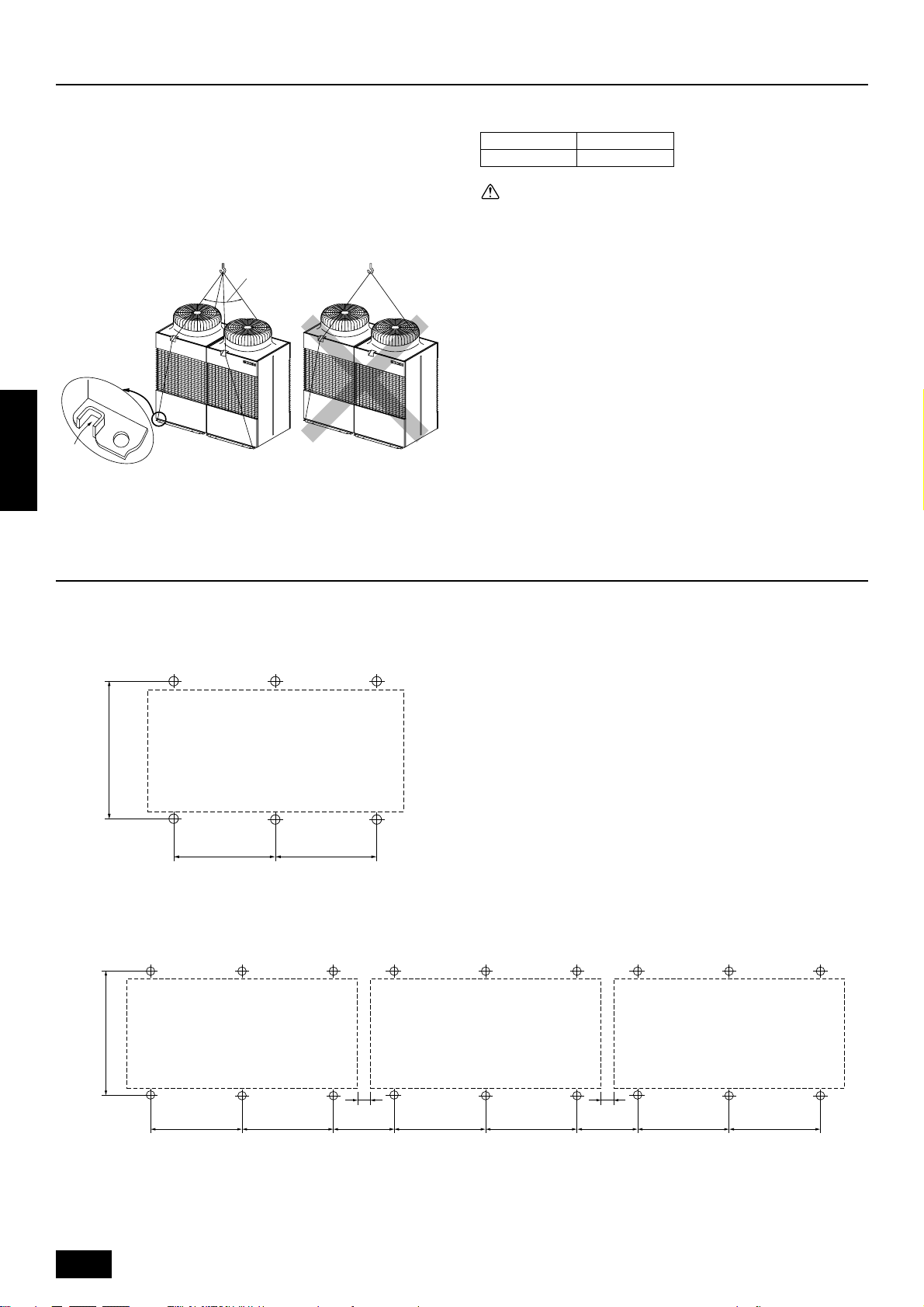
7. Lifting method and weight of product
• When carrying the unit suspended, pass the ropes under the unit
and use the two suspension points each at the front and rear.
• Always lift the unit with ropes attached at four points so that impact is
not applied to the unit.
• Attach the ropes to the unit at an angle of 40° or less.
• Use two ropes at least 8 m long.
A
B
Dangerous!
ENGLISH
A 40° or less
B Rope suspension part
Weight of product:
PUHY-P400 PUHY-P500
455 kg 475 kg
Caution:
Be very careful to carry product.
- Do not have only one person to carry product if it is more than 20 kg.
- PP bands are used to pack some products. Do not use them as a
mean for transportation because they are dangerous.
- Do not touch heat exchanger fins with y our bare hands. Otherwise you
may get a cut in your hands.
- Tear plastic packaging bag and scrap it so that children cannot play
with it. Otherwise plastic pac kaging bag may suffocate children to death.
- When carrying in outdoor unit, be sure to support it at four points. Carrying in and lifting with 3-point support may make outdoor unit unstable, resulting in a fall of it.
8. Installation of unit
8.1. Location of anchor bolt
• Individual installation
880±5
780±2
• Example of collective installation
780±2
A
880±5
A (Service side)
8
780±2
780±2 440 440780±2 780±2 780±2 780±2
10 10
For collective installation, provide a 10 mm gap between units.
Page 9
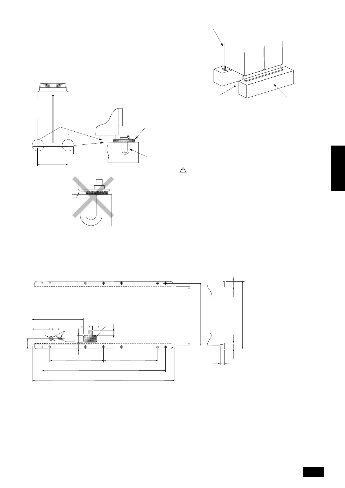
8.2. Installation
• Fix unit tightly with bolts as shown below so that unit will not fall down
due to earthquake or gust.
• Use concrete or angle for foundation of unit.
• Vibration may be transmitted to the installation section and noise
and vibration may be generated from the floor and walls, depending
on the installation conditions. Therefore, provide ample
vibrationproofing (cushion pads, cushion frame, etc.).
D
A
880±5
B
C
Down piping and down wiring precautions
When down piping and down wiring are performed, be sure that foundation and base work does not block the base through holes. When down
piping is performed, make the foundation at least 100 mm high so that
the piping can pass under the bottom of the unit.
E
A Be sure that the corners are firmly seated. If the corners are not firmly
seated, the installation feet may be bent.
B M10 anchor bolt procured at the site
C Corner is not seated.
D Unit
(Provide ample vibrationproofing between the unit and the foundation by
using cushion pads, cushion frame, etc.)
E Piping and wiring space (Bottom piping, bottom wiring)
F Concrete foundation
F
Warning:
• Be sure to install unit in a place strong enough to withstand its
weight.
Any lack of strength may cause unit to fall down, resulting in a
personal injury.
• Have installation work in order to protect against a str ong wind
and earthquake.
Any installation deficiency may cause unit to fall down, resulting in a personal injury.
When building the foundation, give full attention to the floor strength,
drain water disposal <during operation, drain water flows out of the unit>,
and piping and wiring routes.
ENGLISH
694
230
150
Ø62
111
A Bottom piping through hole
B (bolt hole)
C (bolt hole for old models)
D (unit width)
E (unit depth)
F Bottom wiring through hole
F
Ø27
780
80 82 78
90
73
B
1760
1990
5656
840 E
A
80
780
B
C
D
880 B
15
910
9
Page 10
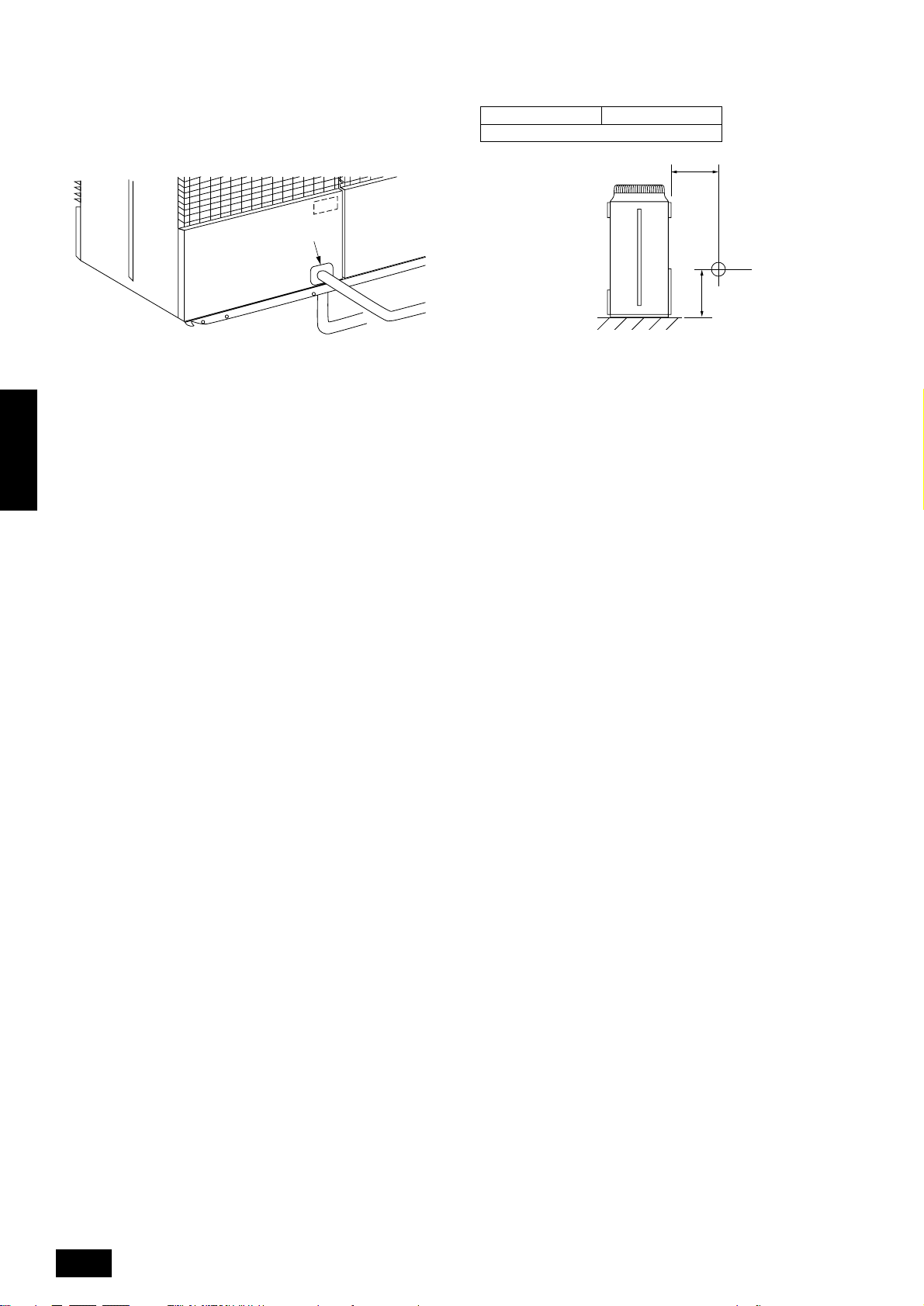
8.3. Connecting direction for refrigerant
piping
Two connecting directions are available f or refriger ant piping of the outdoor unit, bottom piping and front piping, as shown below:
8.4. Noise level
(50/60Hz)
PUHY-P400 PUHY-P500
60/61 dB(A)
1m
A
B
A Knock-out hole
B Bottom piping
C Front piping
Note:
In the case of bottom piping, build a 100 mm or higher foundation
so that piping will go through the bottom of the unit.
ENGLISH
C
A
1m
B
A Front
B Measuring point
Measuring location: a room free from echoes and reverberations
10
Page 11
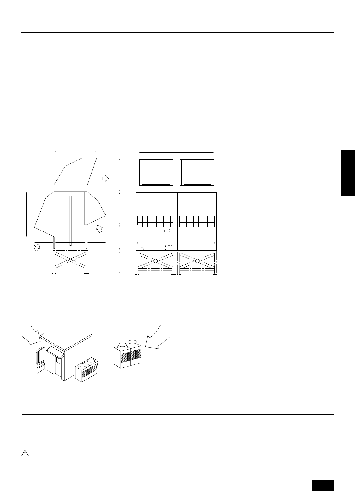
9. Caution for snow and seasonal wind
In cold and/or snowy areas, sufficient countermeasures to wind and snow
damages should be taken for operating unit in normal and good condition in winter time. Ev en in the other areas, full consider ation is required
for installation of unit in order to prevent abnormal operations caused by
seasonal wind or snow. When rain and snow directly fall on unit in
the case of air-conditioning operations in 10 or less degrees centigrade outdoor air, mount inlet and outlet ducts on unit for assuring
stable operations.
9.1. Snow and seasonal wind
■ Prevention of wind and snow damages in cold or snowy areas:
Refer to the figure of snow hood shown below:
• Snow hood
1093
A
Note:
1. Height of frame base for snow damage prevention (H) shall be
twice as high as expected snowfall. Width of frame base shall
not exceed that of the unit. The frame base shall be made of
angle steel, etc., and designed so that sno w and wind slip through
the structure. (If frame base is too wide, snow will be accumulated on it.)
2. Install unit so that seasonal wind will not directly lash against
openings of inlet and outlet ducts.
3. Build frame base at customer referring to this figure.
Material : Galvanized steel plate 1.2T
Painting : Overall painting with polyester powder
Color : Munsell 5Y8/1 (same as that of unit)
4. When the unit is used in a cold region and the heating operation
is continuously performed for a long time when the outside air
temperature is below freezing, install a heater to the unit base
or take other appropriate measures to prevent water from freezing on the base.
1888
ENGLISH
1145
B
500(840)500
(670) 821 903
(1990)
B
H
A Outlet
B Inlet
9.2. Countermeasure to seasonal wind
Referring to the figure shown below, take appropriate measures which
will suit the actual situation of the place for installation.
AA
A Seasonal wind
10. Refrigerant piping installation
Connecting the piping is a terminal-branch type in which refrigerant piping from the outdoor unit is branched at the terminal and connected to each of
the indoor units.
The method of connection consists of flare connections at the indoor units, flange connections for the piping of the outdoor unit and flare connections
for the liquid piping. Note that the branched sections are brazed.
Warning:
Always use extreme care to prevent the refrigerant gas (R22) from leaking while using fire or flame. If the refrigerant gas comes in contact
with the flame from any source, suc h as a gas sto ve, it breaks down and generates a poisonous gas which can cause gas poisoning. Never
weld in an unventilated room. Always conduct an inspection for gas leakage after installation of the refrigerant piping has been completed.
11
Page 12
10.1. Areas of caution
1 Use the following materials for refrigeration piping.
• Material: Seamless phosphorous deoxidized copper pipe, C1220T-OL or C1220T-O (Note: C1220T-OL is preferred.)
13
• Size: Refer to Pages
2 Commercially available piping often contains dust and other materials. Always blow it clean with a dry inert gas.
3 Use care to prevent dust, water or other contaminants from entering the piping during installation.
4 Reduce the number of bending portions as much as possible, and make bending radius as big as possible.
5 Always use the branch piping set shown below, which are sold separately.
Total of units down-
stream less than 160
CMY-Y102S-F CMY-Y102L-F CMY-Y202-F CMY-Y104-E CMY-Y107-E CMY-Y1010-E
6 If the diameters of the branch piping of the designated refrigerant piping differs, use a pipe cutter to cut the connecting section and then use an
adapter for connecting different diameters to connect the piping.
7 Always observe the restrictions on the refrigerant piping (such as rated length, the difference between high/low pressures, and piping diameter).
Failure to do so can result in equipment failure or a decline in heating/cooling performance.
8 A second branch cannot be made after a header branch. (These are shown by ×.)
to 14.
Branch pipe set name
Line branching Header branching
Total of units down-
stream 161 to 330
Total of units down-
stream more than 331
4 branching 7 branching 10 branching
A
ENGLISH
A To Outdoor Unit
B Capped Piping
9 Always use good-quality materials for brazing.
0 The City Multi Series Y will stop due an abnormality due to excessive or insufficient coolant. At such a time , alwa ys properly charge the unit. When
servicing, always check the notes concerning pipe length and amount of additional refrigerant at both locations, the refrigerant volume calculation
table on the back of the service panel and the additional refrigerant section on the labels for the combined number of indoor units. (Refer to Pages
13
to 14.)
A Use liquid refrigerant to fill the system.
B Never use refrigerant to perform an air purge. Always evacuate using a vacuum pump.
C Always insulate the piping properly. Insufficient insulation will result in a decline in heating/cooling performance, water drops from condensation
and other such problems. (Refer to Pages 21 to
D When connecting the refrigerant piping, make sure the ball valve of the outdoor unit is completely closed (the factory setting) and do not operate it
until the refrigerant piping for the outdoor and indoor units has been connected, a refrigerant leakage test has been performed and the evacuation
process has been completed.
E Always use a non-oxidizing brazing material for brazing the parts. If a non-oxidizing brazing material is not used, it could cause clogging or damage
to the compressor unit. (Details of the piping connections and valve operation can be found on Pages 15 to 16.)
F Never perform outdoor unit piping connection work when it is raining.
22
.)
A
B
Warning:
When installing and moving the air conditioner to another site, do not charge the it with a refrigerant different from the refrigerant (R407C)
specified on the unit.
- If a different refrigerant or air is mixed with the original refrigerant, the refrigerant cycle may malfunction and the unit may be damaged.
Caution:
• Use refrigerant piping made of C1220T-OL phosphorus deoxidized copper. In addition, be sure that the inner and outer surfaces of the
pipes are clean and free of hazardous sulphur, oxides, dust/dirt, shaving particles, oils, moisture, or any other contaminant.
- Contaminants on the inside of the refrigerant piping may cause the refrigerant residual oil to deteriorate.
• Use liquid refrigerant for sealing.
- Sealing with gas refrigerant will change the composition of the refrigerant in the cylinder and reduce the unit’s performance.
• Never use existing refrigerant piping.
- The large amount of chlorine in conventional refrigerant and refrigerator oil in the existing piping will cause the new refrigerant to deteriorate.
• Store the piping to be used during installation indoors and keep both ends of the piping sealed until just before brazing.
- If dust, dirt, or water gets into the refrigerant cycle, the oil will deteriorate and the compressor may fail.
• Do not use a charging cylinder.
- Using a charging cylinder may cause the refrigerant to deteriorate.
12
Page 13
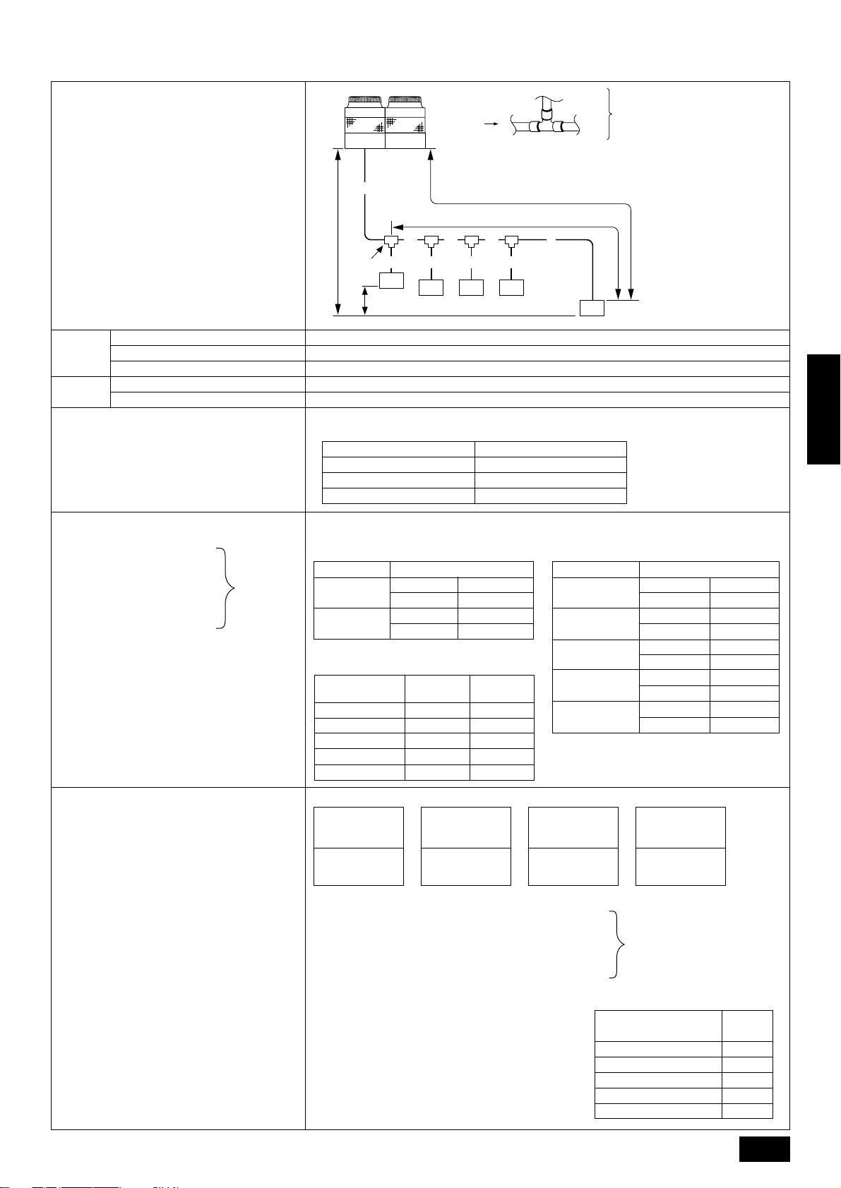
10.2. Refrigerant piping system
Line-Branch Method
Connection Examples
(Connecting to Five Indoor Units)
Permissible
Length
Permissible High/
Low Difference
Total Piping Length
Farthest Piping Length (L)
Farthest Piping Length After First Branch (r)
High/Low Difference in Indoor/Outdoor Section (H)
High/Low Difference in Indoor/Indoor Section (h)
■ Selecting the Refrigerant Branch Kit
Use the table to the right to make the selection
based on the model total of indoor units downstream from the branch section.
■ Select Each Section of Refrigerant Piping
(1) Section From Outdoor Unit
to First Branch (A)
(2) Sections From Branch to
Indoor Unit (a,b,c,d,e)
(3) Section From Branch to
Each
Section of
Piping
Branch (B, C, D)
Select the size from the table to the right.
C
D
5
A
A
A
H
B
h
B C D
a b c d
C
C2C3C
1
L
R
e
4
Note:
The model total for down-
stream units shown in the
table below is the model
total when viewed from
Point A in the drawing
above.
A Outdoor Unit
B First Branch
The first branch on the
outdoor unit must be
the CMY-Y202-F.
C Indoor unit
D To downstream units
A+B+C+D+a+b+c+d+e is 220 m or less
A+B+C+D+e is 100 m or less
B+C+D+e is 30 m or less
50 m or less (If the outdoor unit is lower, 40 m or less)
15 m or less
Select the branch kit, sold separately , from the tab le below. (Each kit contains a refrigerant and
gas piping set.)
Downstream Unit Model Total Branch Kit Model
160 or less CMY-Y102S-F
161 to 330 CMY-Y102L-F
331 or more CMY-Y202-F
(1) Refr igerant Piping Diameter In Section
From Outdoor Unit to First Branch (Outdoor Unit Piping Diameter)
Model Piping Diameter (mm)
PUHY-P400
PUHY-P500
Liquid Line ø15.88
Gas Line ø31.75
Liquid Line ø15.88
Gas Line ø38.1
(3) Refr igerant Piping Diameter In Section
From Branch to Branch
Downstream Unit
Model Total
80 or less
81 to 160
161 to 330
331 to 480
481 or more
Liquid Line
(mm)
ø9.52
ø12.7
ø12.7
ø15.88
ø15.88
Gas Line
(mm)
ø15.88
ø19.05
ø25.4
ø31.75
ø38.1
(2) Refr igerant Piping Diameter In Section
From Branch to Indoor Unit (Indoor Unit
Piping Diameter)
Model number Piping dia. (mm)
25 · 32 · 40
50 · 63 · 71 · 80
100 · 125 · 140
200
250
Liquid Line ø6.35
Gas Line ø12.7
Liquid Line ø9.52
Gas Line ø15.88
Liquid Line ø9.52
Gas Line ø19.05
Liquid Line ø12.7
Gas Line ø25.4
Liquid Line ø12.7
Gas Line ø28.58
ENGLISH
■ Additional Refrigerant Charge
At the time of shipping, the outdoor unit PUHY -P400
is charged with 16 kg of refrigerant and the PUHYP500 is charged with 22 kg. As this charge does not
include the amount needed for extended piping, additional charging for each refrigerant line will be required on site. In order that future servicing may be
properly provided, always keep a record of the size
and length of each refrigerant line and the amount of
additional charge by writing it in the space provided
on the outdoor unit.
■ Calculation of Additional Refrigerant Charge
• Calculate the amount of additional charge based
on the length of the piping extension and the size
of the refrigerant line.
• Use the table to the right as guide to calculating
the amount of additional charging and charge the
system according.
• If the calculation results of the calculation result
in a fraction of less than 0.1 kg, round up to the
next 0.1 kg. F or example , if the result of the calculation was 16.76 kg, round the result up to 16.8
kg.
<Additional Charge>
Liquid pipe size
Total length of
ø15.88 × 0.25
(m) × 0.25 (kg/m)
Liquid pipe size
Total length of
ø12.7 × 0.12
++++ α
(m) × 0.12 (kg/m)
Liquid pipe size
Total length of
ø9.52 × 0.06
(m) × 0.06 (kg/m)
<Example>
Indoor 1 : 125 A : ø15.88 40 m a : ø9.52 10 m
2 : 100 B : ø12.7 10 m b : ø9.52 10 m
3:50 C:ø12.7 5 m c : ø9.52 10 m
4:32 D:ø9.52 5 m d : ø6.35 5 m
5:32 e:ø6.35 10 m
The total length of each liquid line is as follows:
ø15.88 : A = 40 m
ø12.7 : B + C = 10 + 5 = 15 m
ø9.52 : D + a + b + c = 5 + 10 + 10 + 10 = 35 m
ø6.35 : d + e = 5 + 10 = 15 m
Therefore,
<Calculation example>
Additional
refrigerant charge = 40 × 0.25 + 15 × 0.12 + 35 × 0.06
+ 15 × 0.024 + 2.5 = 16.8 kg
Liquid pipe size
Total length of
ø6.35 × 0.024
(m) × 0.024 (kg/m)
At the conditions
below:
Value of α
Total capacity of
connecting indoor units
to Model 80 1.0 kg
Models 81 to 160 1.5 kg
Models 161 to 330 2.0 kg
Models 331 to 480 2.5 kg
Models 481 or more 3.0 kg
α
13
Page 14
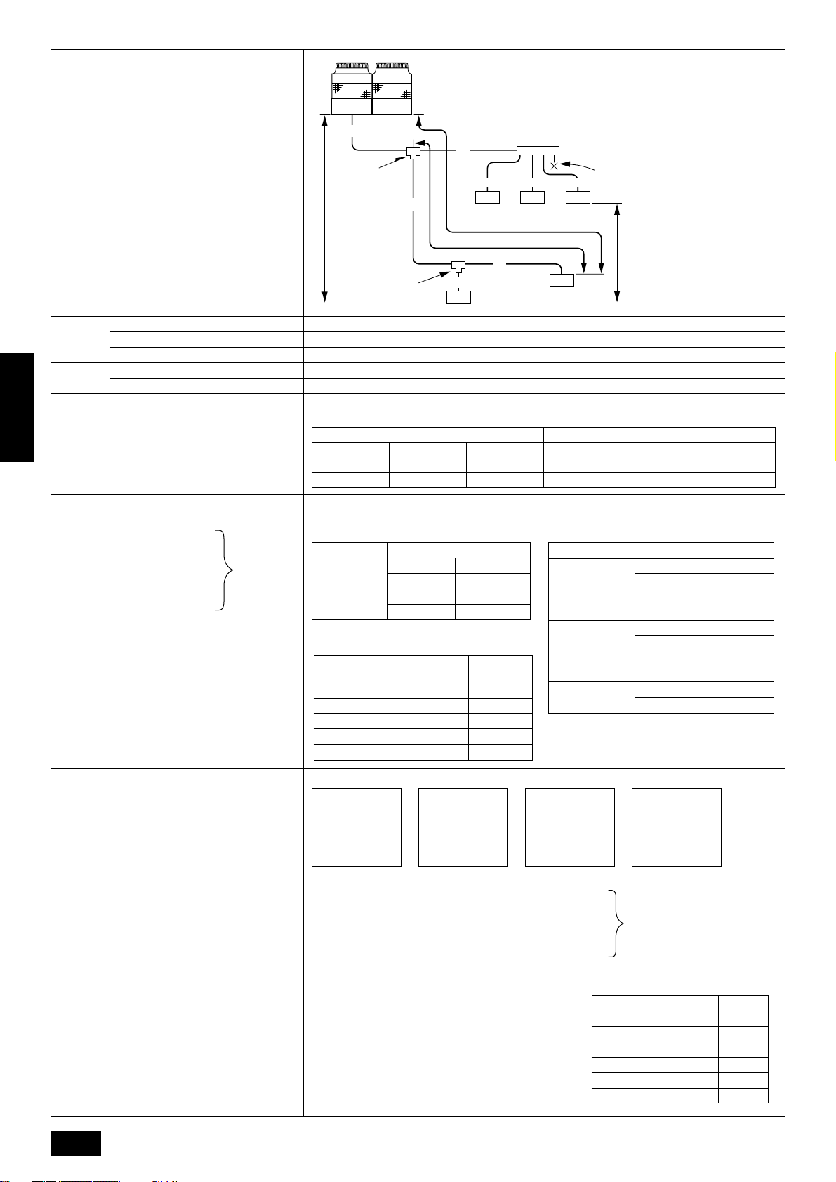
Multiple Line/Header
Connection Example
(When Connecting Five Indoor Units)
Permissible
Length
Permissible High/
Low Difference
Total Piping Length
Farthest Piping Length (L)
Farthest Piping Length After First Branch (r)
High/Low Difference in Indoor/Outdoor Section (H)
High/Low Difference in Indoor/Indoor Section (h)
■ Selecting the Refrigerant Branch Kit
Use the table to the right to make the selection
based on the model total of indoor units down-
ENGLISH
stream from the branch section or on the number
of indoor units to be connected on the header
branch.
■ Select Each Section of Refrigerant Piping
(1) Section From Outdoor Unit
to First Branch (A)
(2) Sections From Branch to
Indoor Unit (a,b,c,d,e)
(3) Section From Branch to
Branch (B, C)
Select the size from the table to the right.
Each
Section of
Piping
Note:
A
A
C
B
H
B
C
1
c
34
D
L
R
b
a
D
D
E
F
d
e
5
D
2
D
• Branch piping cannot be used
again after the header branch.
• The model total for downstream units shown in the table below is the model total
when viewed from Point A in
the drawing above.
A Outdoor Unit
B First Branch (Branch Joint)
The first branch must be the
CMY-Y202-F when the outdoor unit and header branch
h
are to be used.
C Branch Joint
D Indoor Unit
E Branch Header
F Cap
A+B+C+a+b+c+d+e is 220 m or less
A+B+b is 100 m or less
B+b is 30 m or less
50 m or less (If the outdoor unit is lower, 40 m or less)
15 m or less
Select the branch kit, sold separately , from the tab le below. (Each kit contains a refrigerant and
gas piping set.)
Line branching Header branching
Total of units downstream
less than 160
Total of units downstream
161 to 330
Total of units downstream
more than 331
4 branching
header
7 branching
header
10 branching
header
CMY-Y102S-F CMY-Y102L-F CMY-Y202-F CMY-Y104-E CMY-Y107-E CMY-Y1010-E
(1) Refr igerant Piping Diameter In Section
From Outdoor Unit to First Branch (Outdoor Unit Piping Diameter)
Model Piping Diameter (mm)
PUHY-P400
PUHY-P500
Liquid Line ø15.88
Gas Line ø31.75
Liquid Line ø15.88
Gas Line ø38.1
(3) Refr igerant Piping Diameter In Section
From Branch to Branch
Downstream Unit
Model Total
80 or less
81 to 160
161 to 330
331 to 480
481 or more
Liquid Line
(mm)
ø9.52
ø12.7
ø12.7
ø15.88
ø15.88
Gas Line
(mm)
ø15.88
ø19.05
ø25.4
ø31.75
ø38.1
(2) Refrigerant Piping Diameter In Section
From Branch to Indoor Unit (Indoor Unit
Piping Diameter)
Model number Piping dia. (mm)
25 · 32 · 40
50 · 63 · 71 · 80
100 · 125 · 140
200
250
Liquid Line ø6.35
Gas Line ø12.7
Liquid Line ø9.52
Gas Line ø15.88
Liquid Line ø9.52
Gas Line ø19.05
Liquid Line ø12.7
Gas Line ø25.4
Liquid Line ø12.7
Gas Line ø28.58
■ Additional Refrigerant Charge
At the time of shipping, the outdoor unit PUHYP400 is charged with 16 kg of refrigerant and the
PUHY -P500 is charged with 22 kg. As this charge
does not include the amount needed for extended
piping, additional charging for each refrigerant
line will be required on site. In order that future
servicing may be properly provided, always keep
a record of the size and length of each refrigerant line and the amount of additional charge by
writing it in the space provided on the outdoor
unit.
■ Calculation of Additional Refrigerant Charge
• Calculate the amount of additional charge
based on the length of the piping extension
and the size of the refrigerant line.
• Use the table to the right as guide to calculating the amount of additional charging and
charge the system according.
• If the calculation results of the calculation result in a fraction of less than 0.1 kg, round up
to the next 0.1 kg. For example, if the result
of the calculation was 14.32 kg, round the
result up to 14.4 kg.
14
<Additional Charge>
Liquid pipe size
Total length of
ø15.88 × 0.25
(m) × 0.25 (kg/m)
Liquid pipe size
Total length of
ø12.7 × 0.12
++++ α
(m) × 0.12 (kg/m)
Liquid pipe size
Total length of
ø9.52 × 0.06
(m) × 0.06 (kg/m)
<Example>
Indoor 1 : 125 A : ø15.88 30 m a : ø9.52 10 m
2 : 100 B : ø12.7 10 m b : ø9.52 20 m
3:40 C:ø12.7 15 m c : ø6.35 10 m
4:32 d:ø6.35 10 m
5:32 e:ø6.35 10 m
The total length of each liquid line is as follows:
ø15.88 : A = 30 m
ø12.7 : B + C = 10 + 15 = 25 m
ø9.52 : a + b = 10 + 20 = 30 m
ø6.35 : c + d + e = 10 + 10 + 10 = 30 m
Therefore,
<Calculation example>
Additional
refrigerant charge = 30 × 0.25 + 15 × 0.12 + 30 × 0.06
+ 30 × 0.024 + 2.5 = 14.4 kg
Liquid pipe size
Total length of
ø6.35 × 0.024
(m) × 0.024 (kg/m)
At the conditions
below:
Value of α
Total capacity of
connecting indoor units
to Model 80 1.0 kg
Models 81 to 160 1.5 kg
Models 161 to 330 2.0 kg
Models 331 to 480 2.5 kg
Models 481 or more 3.0 kg
α
Page 15
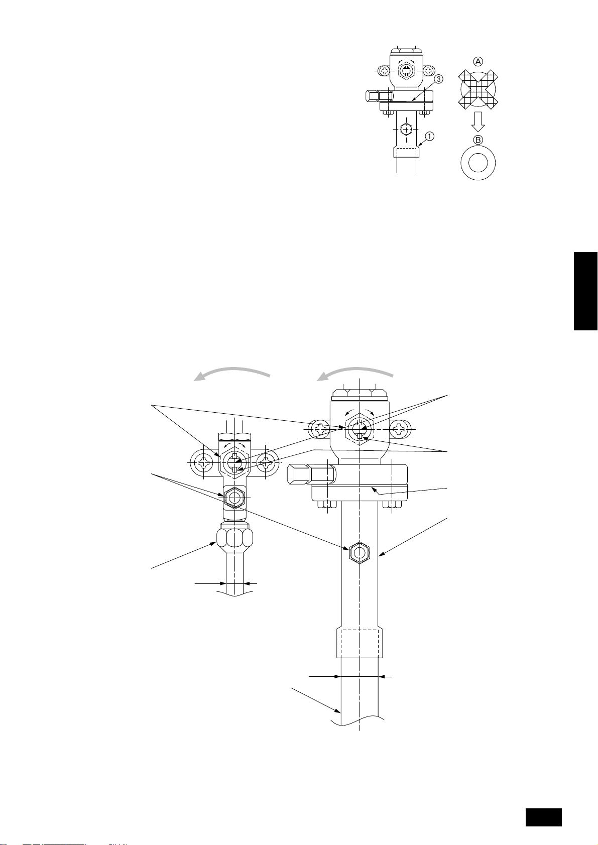
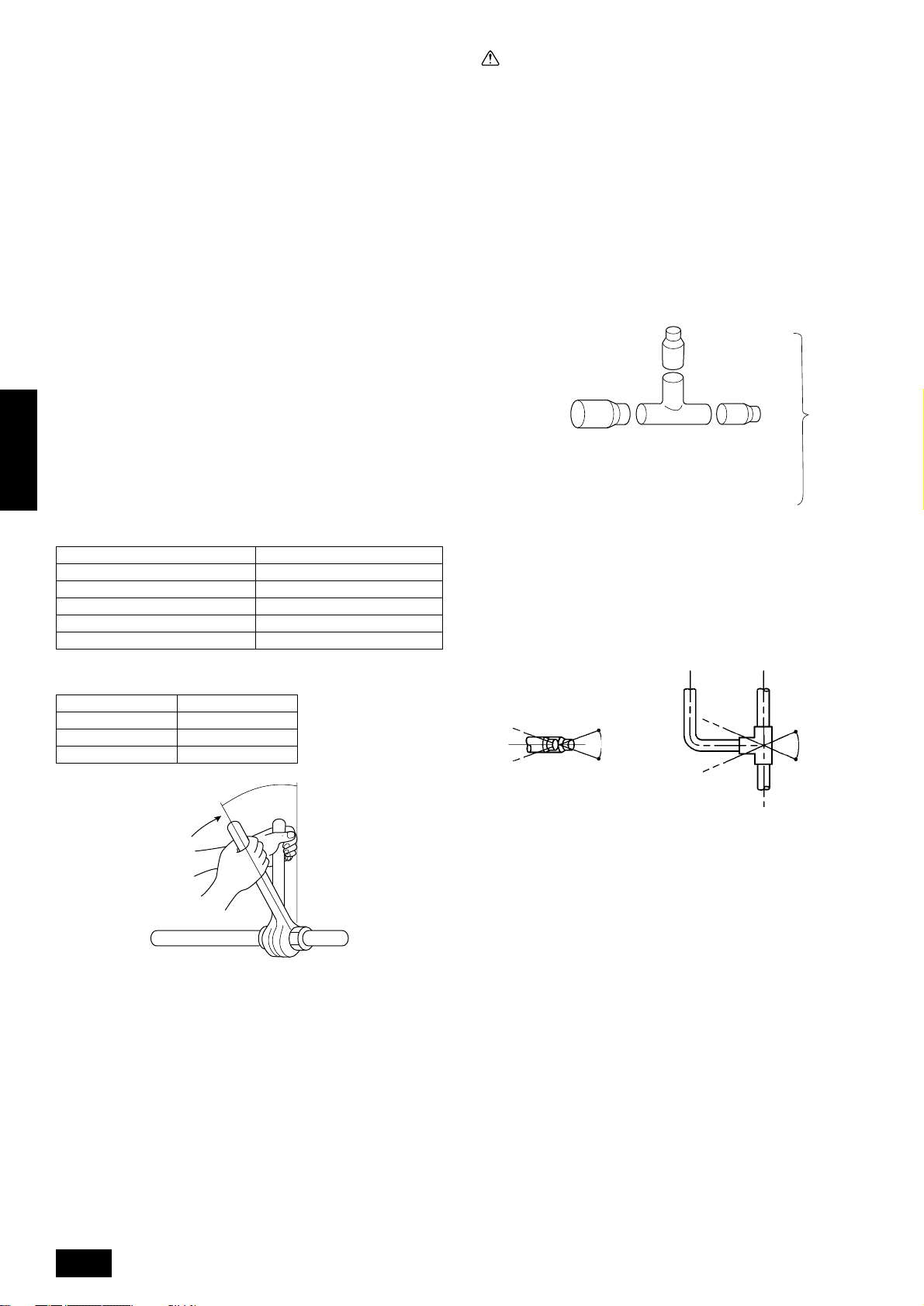
10.3. Caution for piping connection/valve
operation
• Conduct piping connection and valve operation accurately b y follo w-
ing the figure below.
• The gas side connecting pipe is being assembled for shipment.
(See the figure at the right.)
1 For brazing to the connecting pipe with flange, remove the con-
necting pipe with flange from the ball valve, and braze it at the
outside of the unit.
2 During the time when removing the connecting pipe with flange,
remove the seal attached on the back side of this sheet and paste
it onto the flange surface of the ball valve to prevent the entry of
dust into the valve.
3 The refrigerant circuit is closed with a round, close-packed pack-
ing at the shipment to prevent gas leak between flanges. As no
operation can be done under this state, be sure replace the packing with the hollow packing attached at the piping connection.
4 At the mounting of the hollow packing, wipe off dust attached on
the flange sheet surface and the packing. Coat refrigerating machine oil onto both surfaces of the packing.
A
3
1
A Replace the close-packed packing
B Hollow packing
• After evacuation and refrigerant charge, ensure that the handle is
fully open. If operating with the v alve closed, abnormal pressure will
be imparted to the high- or low-pressure side of the refrigerant circuit, giving damage to the compressor, four-w ay valve, etc.
• Determine the amount of additional refrigerant charge by using the
formula, and charge refrigerant additionally through the service port
after completing piping connection work.
• After completing work, tighten the service port and cap securely not
to generate gas leak.
B
ENGLISH
F
G
H
[Ball valve (liquid side)] [Ball valve (gas side)]
EE
O
S
O
S
I
A
B
C
D
J
K
(This figure shows the valve in the fully open state.)
15
Page 16
A Valve stem
[Fully closed at the factory , when connecting the piping, when evacuating,
and when charging additional refrigerant. Open fully after the operations
above are completed.]
B Stopper pin [Prevents the valve stem from turning 90° or more.]
C Packing (Accessory)
D Connecting pipe (Accessory)
[Use packing and securely install this pipe to the valve flange so that gas
leakage will not occur. (Tightening torque: 43 N·m (430 kg-cm)) Coat both
surfaces of the packing with refrigerator oil.]
E Open (Operate slowly)
F Cap, copper packing
[Remove the cap and operate the valv e stem. Alwa ys reinstall the cap after
operation is completed. (Valve stem cap tightening torque: 25 N·m (250
kg-cm) or more)]
G Service port
[Use this port to evacuate the refrigerant piping and add an additional charge
at the site.
Open and close the port using a double-ended wrench.
Always reinstall the cap after operation is completed. (Service port cap
tightening torque: 14 N·m (140 kg-cm) or more)]
H Flare nut
[Tightening torque: 80 N·m (800 kg-cm)
Loosen and tighten this nut using a double-ended wrench.
Coat the flare contact surface with refrigerator oil.]
I ø15.88
J ø31.75 (PUHY-P400)
ø38.1 (PUHY-P500)
K Field piping
ENGLISH
[Braze to the connecting pipe. (When brazing, use unoxidized brazing.)]
Appropriate tightening torque by torque wrench
Copper pipe external dia. (mm) Tightening torque (N·m) / (kg-cm)
ø6.35 14 to 18 / 140 to 180
ø9.52 35 to 42 / 350 to 420
ø12.7 50 to 57.5 / 500 to 575
ø15.88 75 to 80 / 750 to 800
ø19.05 100 to 140 / 1000 to 1400
Tightening angle standard
Caution:
• Always remove the connecting pipe from the ball valve and braze
it outside the unit.
- Brazing the connecting pipe while it is installed will heat the ball
valve and cause trouble or gas leakage. The piping, etc. inside the
unit may also be burned.
• Use ester oil, ether oil or alkylbenzene (small amount) as the
refrigerator oil to coat flares and flange connections.
- The refrigerator oil will degrade if it is mixed with a large amount of
mineral oil.
10.4. How to install branch pipe
For detail, please observe the instruction manual attached to the optional refrigerant branch kit.
■ Joint
A
A To Outdoor Unit
B To Branch Piping or Indoor Unit
• Apart from the CMY -Y202-F gas side, there are no restrictions on the
posture for attaching joints.
• Ensure that the branch pipes for the CMY-Y202-F gas side are attached horizontally or facing upwards. (See the diagram below.)
Horizontal Facing upwards
(Facing downwards is not possible)
B
Pipe diameter (mm) Tightening angle (°)
ø6.35, ø9.52 60 to 90
ø12.7, ø15.88 30 to 60
ø19.05 20 to 35
Note:
If a torque wrench is not available, use the following method as a
standard.
When you tighten the flare nut with a wrench, y ou will reach a point
where the tightening torque will abrupt increase. Turn the flare nut
beyond this point by the angle shown in the table above.
Within ± 15˚
Within ± 15˚
Within ± 15˚
• There is no limitation on the joint mounting configuration.
• If the diameter of the refrigerant piping selected by the procedures
described on pages 13 to 14 is different from the size of the joint,
match the sizes using a deformed joint. The deformed joint is included with the kit.
16
Page 17

■ Header
C
D
A
B
A To outdoor unit
B To indoor unit
• No restriction is applied to the mounting posture of the header.
• If the diameter of the refrigerant piping selected using the proce-
dures described on pages 14 and the size of the joint is different,
match the sizes using a deformed joint. The deformed joint is included with the kit.
C Pipe cutter
D or
E Deformed joint
• When the number of pipes to be connected is smaller than the number
of header branches, install a cap to the unconnected branches. The
cap is included with the kit.
E
ENGLISH
17
Page 18
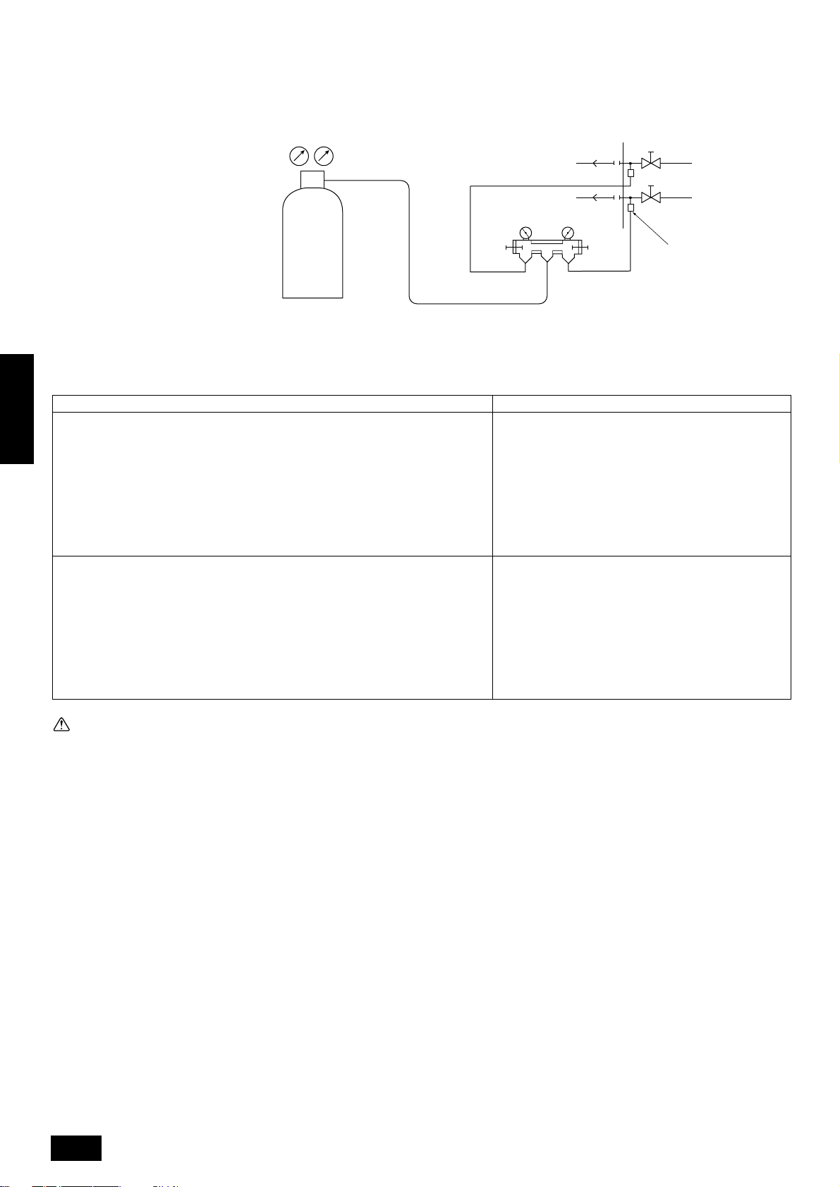
10.5. Airtight test and evacuation, refrigerant charging
1 Airtight test
Perform with the stop valv e of the outdoor unit closed, and pressurize the connection piping and the indoor unit from the service port provided on the
stop valve of the outdoor unit. (Always pressurize from both the liquid pipe and the gas pipe service ports.)
A Nitrogen gas
B To indoor unit
C System analyzer
D Lo Knob
E Hi Knob
F Ball valve
G Liquid pipe
H Gas pipe
I Outdoor unit
J Service port
The method of conducting the airtight test is basically the same as for older models. Howe ver, since the restrictions have a large affect on deterioration
of the refrigerator oil, always observe them. Also, with nonazeotropic refrigerant (R407C, etc.), gas leakage causes the composition to change and
affects performance. Therefore, since the entire amount must be replaced if gas leakage occurs, perform the airtightness test cautiously.
Airtight test procedure
1.Nitrogen gas pressurization
(1) After pressurizing to the design pressure (2.98 MPa) using nitrogen gas, let stand
ENGLISH
for about one day. If the pressure does not drop, airtightness is good.
However, if the pressure drops, since the leaking point is unknown, the following
bubble test may also be performed.
(2) After the pressurization described above, spra y the flare connection parts, brazed
parts, flanges, and other parts that may leak with a bubbling agent (Kyuboflex,
etc.) and visually check for bubbles.
(3) After the airtight test, wipe off the bubbling agent.
2.Pressurization using refrigerant gas and nitrogen gas
(1) After sealing with liquid R407C from a cylinder and pressurizing to a gas pressure
of approximately 0.2 MPa, pressurize to the design pressure (2.98 MPa) using
nitrogen gas.
However , do not pressurize at one time . Stop during pressurization and check that
the pressure does not drop.
(2) Check f or gas leaks by checking the flare connection parts, braz ed parts, flanges,
and other parts which may leak using an R407C compatible electric leak detector.
(3) This test may be used together the with bubble type gas leak test.
A
C
D
B
LO HI
C
LO
HI
E
• If a flammable gas or air (oxygen) is used as the pressurization gas, it may catch fire or explode.
• Do not use a refrigerant other than that indicated on the
unit.
• Sealing with gas from a cylinder will cause the composition of the refrigerant in the cylinder to change.
• Use a pressure gauge, charge box, and other parts especially for R407C.
• An electric leak detector for R22 cannot detect leaks.
• Do not use a haloid torch. (Leaks cannot be detected.)
F
G
H
I
J
Restriction
Caution:
Do not use a refrigerant other than R407C.
- If a refrigerant (R22, etc,) other than R407C is used, the chlorine in the refrigerant will cause the refrigerator oil to deteriorate.
18
Page 19
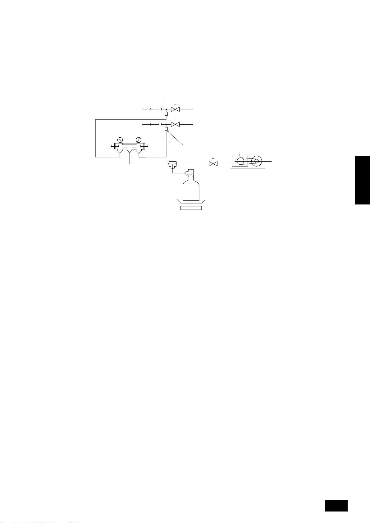
2 Evacuation
As shown in the figure below, evacuate with the stop valve of the outdoor unit closed and evacuate both the connection piping and the indoor unit
from the service port provided on the stop valve of the outdoor unit using a vacuum pump. (Alwa ys e v acuate from the service port of both the liquid
pipe and the gas pipe.) After the vacuum reaches 650 Pa, continue evacuation for at least one hour or more. Then, stop the vacuum pump and let
stand for one day and check if they vacuum does not rise. (If the v acuum rises, since water may be mixed in, pressurize up to 0.05 MPa using dry
nitrogen gas and evacuate again.)
Evacuate from the service port of the ball valve with a vacuum pump.
Finally, seal with liquid refrigerant from the liquid pipe. Moreover, during operation, adjust the refrigerant amount from the gas pipe so that the
refrigerant is always an appropriate amount.
* Never perform air purging using refrigerant.
D
E
F
A
LO HI
LO HI
A System analyzer
B Lo Knob
C Hi Knob
D Ball valve
E Liquid pipe
F Gas pipe
G Service port
H Three-way joint
I Valve
J Valve
K R407C cylinder
B
C
H
G
K
I
J
M
L
L Scale
Use a graviometer. (One that can measure down to 0.1 kg.)
M Vacuum pump
Use a vacuum pump with a reverse flow check valve.
(Recommended vacuum gauge: ROBINAIR 14830A Thermistor Vacuum
Gauge)
Also use a vacuum gauge that reaches 65 Pa or greater after oper ating for
five minutes.
ENGLISH
19
Page 20
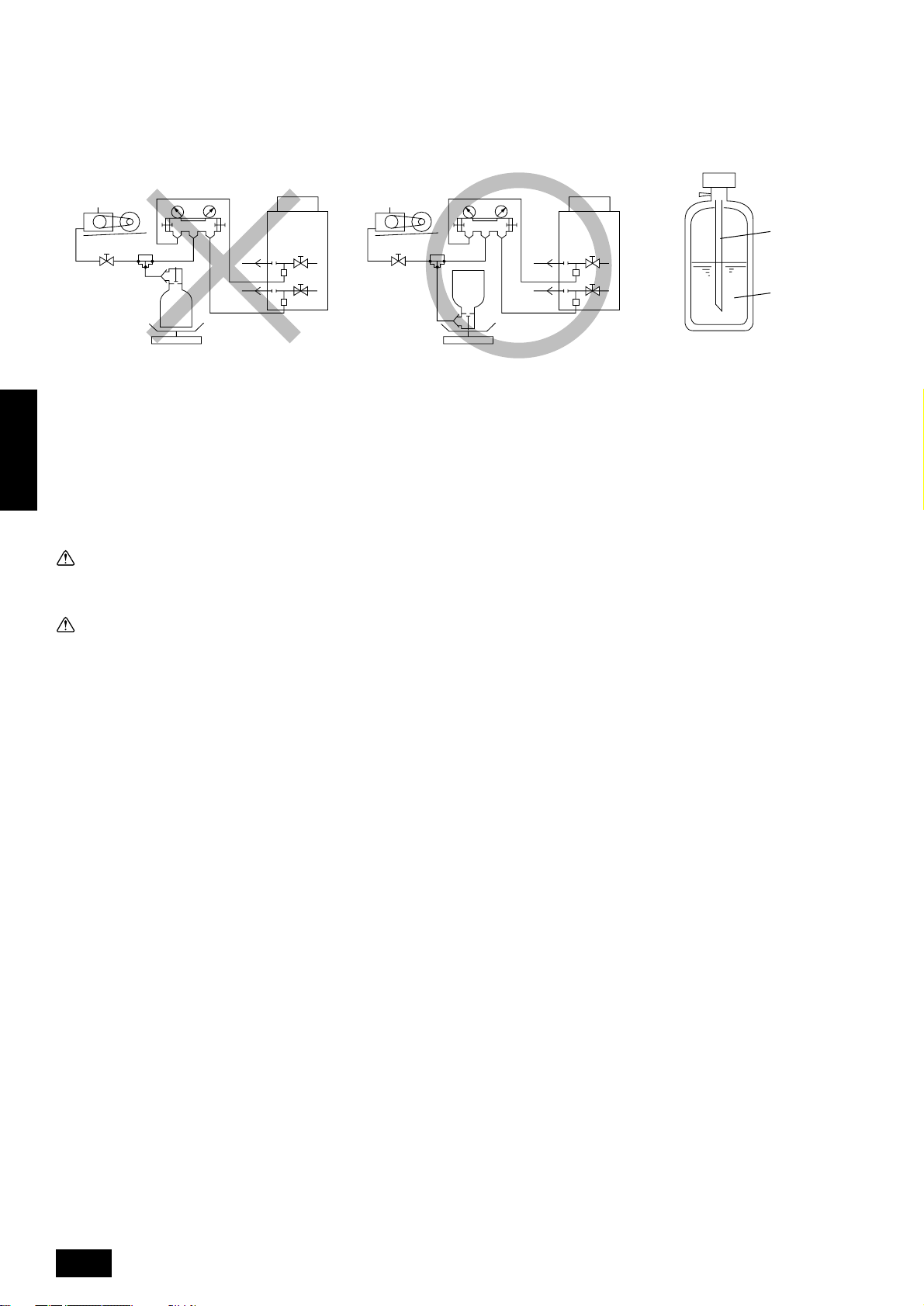
3 Refrigerant Charging
Since the refrigerant used with the unit is nonazerotropic, it must be charged in the liquid state. Consequently , when charging the unit with refrigerant
from a cylinder, if the cylinder does not hav e a syphon pipe, charge the liquid refrigerant by turning the cylinder upside-down as shown below. If the
cylinder has a syphon valve like that shown in the figure at the right, the liquid refrigerant can be charged with the cylinder standing upright.
Therefore, give careful attention to the cylinder specifications. If the unit should be charged with gas refrigerant, replace all the refrigerant with new
refrigerant. Do not use the refrigerant remaining in the cylinder.
B
A
C
A
[When cylinder does not have a syphon pipe] [When cylinder has a syphon pipe
A R407C cylinder
B Syphon pipe
C Liquid refrigerant
Note:
ENGLISH
Always add an appropriate amount of refrigerant. (For the refrigerant additional charge, see pages 13 to 14.) Also always seal the system
with liquid refrigerant. Too much or too little refrigerant will cause trouble.
Use a gauge manifold, charging hose, and other parts for the refrigerant indicated on the unit.
Note that it is not possible to determine if a correct amount is being used with the accumulator level (AL).
(Refrigerant can be charged with the
cylinder standing upright.)]
Warning:
When installing or moving the unit, do not charge it with refrigerant other than the refrigerant (R407C) specified on the unit.
- Mixing of different refrigerant, air, etc. may cause the refrigerant cycle to malfunction and result in severe damage.
Caution:
• Use a vacuum pump with a reverse flow check valve.
- If the vacuum pump does not hav e a re v erse flo w chec k valv e , the v acuum pump oil ma y flow bac k into the refrigerant cycle and cause deterioration of the refrigerator oil and other trouble.
• Do not use a charging cylinder.
- Using a charging cylinder may cause the refrigerant to deteriorate.
• Do not use the tools shown below used with conventional refrigerant.
(Gauge manifold, charge hose, gas leak detector, check valve, refrigerant charge base, vacuum gauge, refrigerant recovery equipment)
- Mixing of conventional refrigerant and refrigerator oil may cause the refrigerator oil to deteriorate.
- Mixing of water will cause the refrigerator oil to deteriorate.
- R407C refrigerant does not contain any chlorine. Therefore, gas leak detectors for conventional refrigerants will not react to it.
• Manage the tools more carefully than normal.
- If dust, dirt, or water gets in the refrigerant cycle, the refrigerator oil will deteriorate.
20
Page 21
10.6. Thermal insulation of refrigerant
piping
Be sure to give insulation work to refrigerant piping by covering liquid
pipe and gas pipe separately with enough thickness heat-resistant
polyethylene, so that no gap is observed in the joint between indoor unit
and insulating material, and insulating materials themselves. When insulation work is insufficient, there is a possibility of condensation drip,
etc. Pay special attention to insulation work to ceiling plenum.
B
A
C
Heat
insulation
material A
Outer
covering B
Note:
When using polyethylene cover as covering material, asphalt roofing shall not be required.
Glass fiber + Steel wire
Adhesive + Heat - resistant polyethylene foam +
Adhesive tape
Indoor Vinyl tape
Floor exposed
Outdoor
Water-proof hemp cloth + Bronze asphalt
Water-proof hemp cloth + Zinc plate + Oily paint
D
A Steel wire
B Piping
C Asphaltic oily mastic or asphalt
D Heat insulation material A
E Outer covering B
• Do not insulate gas or low pressure pipe and liquid or high
pressure pipe together.
Bad example
A
E
B
C
D
E
A
Good example
E
E
B
D
Note:
No heat insulation must be provided for electric wires.
A Liquid pipe
B Gas pipe
C Electric wire
D Finishing tape
E Insulating material
A Liquid pipe
B Gas pipe
D Finishing tape
E Insulating material
ENGLISH
• Be sure to fully insulate connecting portion.
A
A These parts are not insulated.
21
Page 22
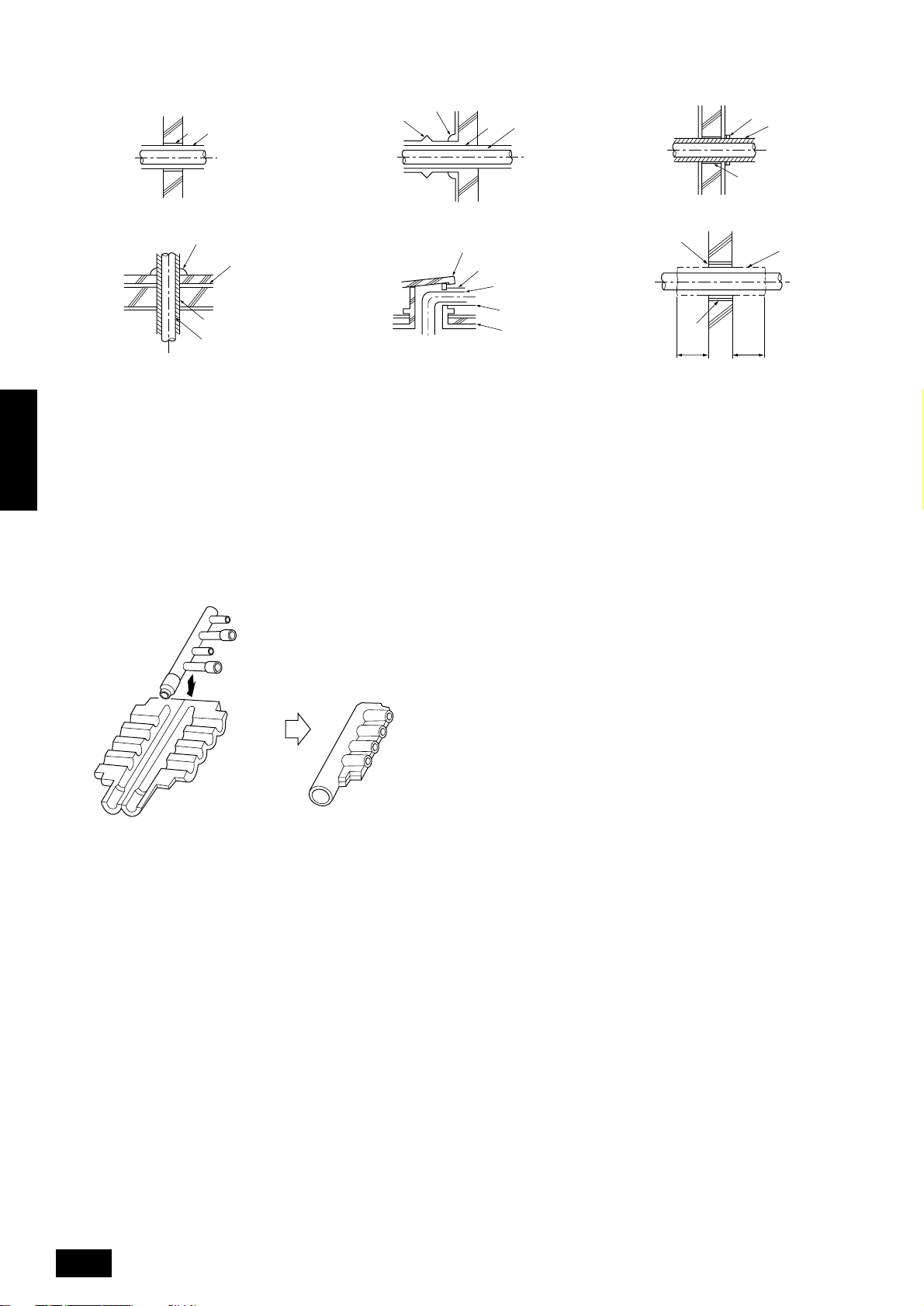
Penetrations
E
I
B
A Sleeve
B Heat insulating material
C Lagging
D Caulking material
E Band
F Waterproofing layer
G Sleeve with edge
ENGLISH
Inner wall (concealed) Outer wall Outer wall (exposed)
D
A B
C
Floor (fireproofing) Roof pipe shaft Penetrating portion on fire limit and boundary wall
D
F
G
A B
D
I
J
B
H
G
B
F
H Lagging material
I Mortar or other incombustible caulking
J Incombustible heat insulation material
When filling a gap with mortar, cover the penetration part with steel plate
so that the insulation material will not be caved in. For this part, use
incombustible materials for both insulation and cov ering. (Vinyl co vering
should not be used.)
A
1m1m
Branch piping section
Insulate the header using
the insulation
material attached to the
branch pipe kit
as shown in the figure.
22
Page 23
11. Electrical work
11.1. Caution
1 Follow ordinance of your governmental organization for technical standard related to electrical equipment, wiring regulations and guidance of each
electric power company.
Warning:
Be sure to have authorized electric engineers do electric work using special circuits in accordance with regulations and this installation
manual. If power supply circuit has a lack of capacity or electric work deficiency, if may cause an electric shock or fire.
2 Install the outdoor unit transmission line away from the power source wiring so that it is not affected by electric noise from the power source . (Do not
run it through the same conduit.)
3 Be sure to provide designated grounding work to outdoor unit.
Caution:
Be sure to put outdoor unit to earth. Do not connect earth line to any gas pipe, water pipe, lightning rod or telephone earth line. If earth is
incomplete, it may cause an electric shock.
4 Give some allowance to wiring for electrical part box of indoor and outdoor units, because the box is sometimes removed at the time of service work.
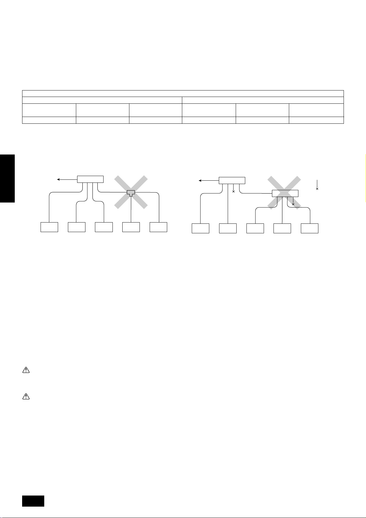
5 Never connect the main power source to terminal block of transmission line. If connected, electrical parts will be burnt out ( mark in the figure
below).
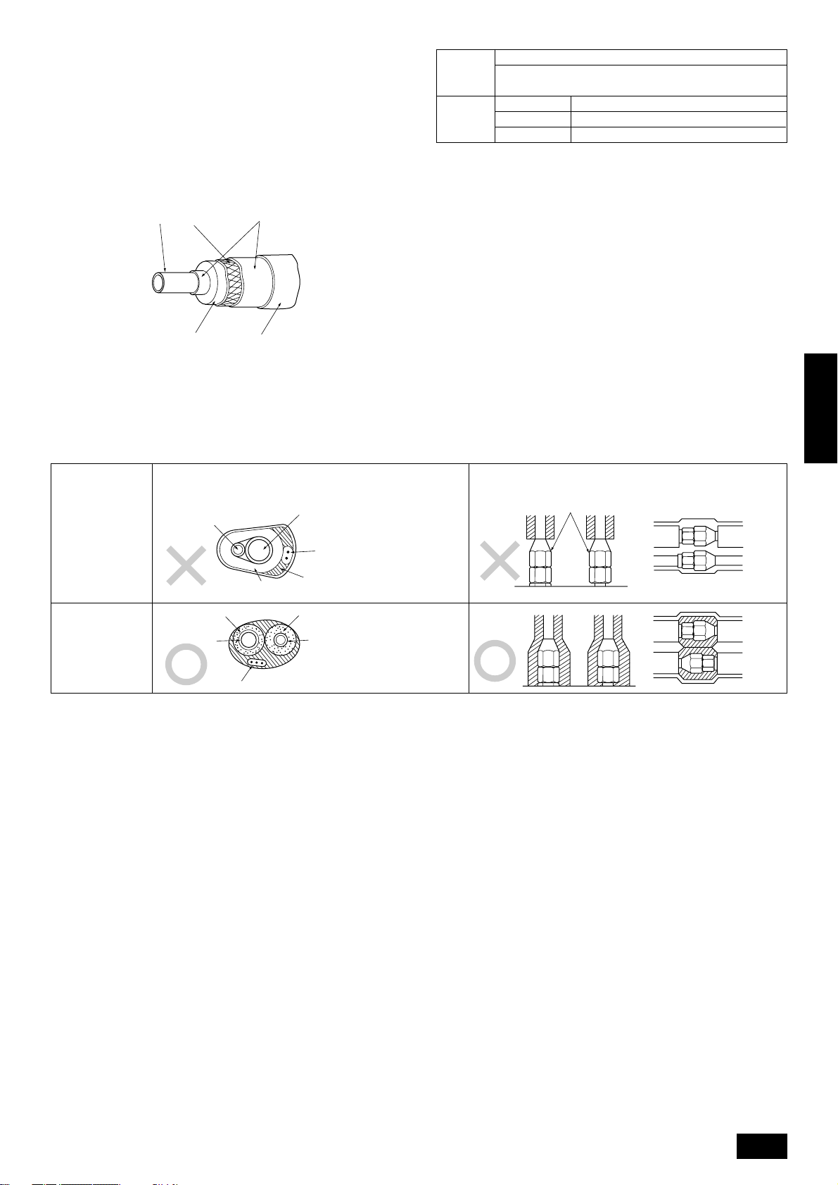
6 Use 2-core shield cable for transmission line. If transmission lines of different systems are wired with the same multiplecore cable , the resultant poor
transmitting and receiving will cause erroneous operations (× mark in the figure below).
7 Only the transmission line specified should be connected to the terminal block for outdoor unit transmission.
(Transmission line to be connected with indoor unit : Terminal block TB3 for transmission line, Other : Terminal block TB7 for centralized control)
Erroneous connection does not allow the system to operate.
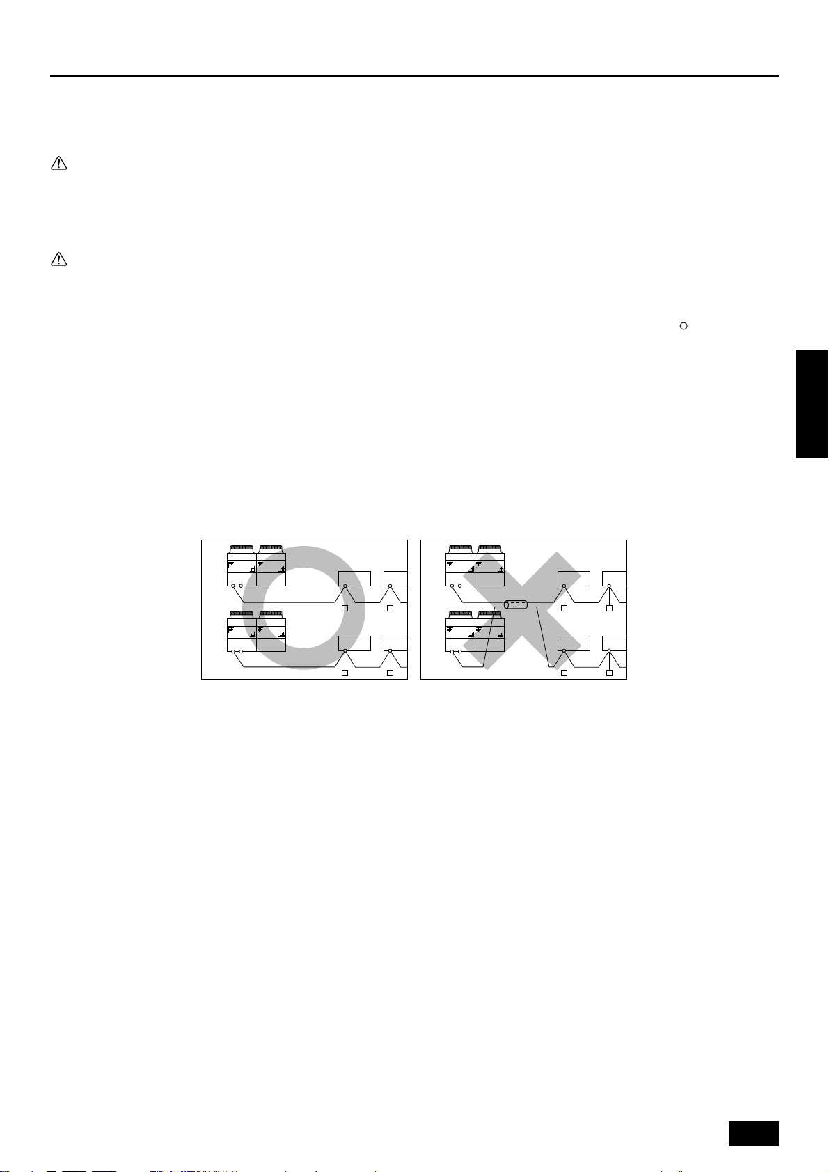
8 In case to connect with the upper class controller or to conduct group operation in different refrigerant systems, the control line for transmission is
required between the outdoor units each other.
Connect this control line between the terminal blocks for centralized control. (2-wire line with no polarity)
When conducting group operation in different refrigerant systems without connecting to the upper class controller, replace the insertion of the short
circuit connector from CN41 of one outdoor unit to CN40.
9 Group is set by operating the remote controller.
ENGLISH
A
C
TB3
TB7
B
D
TB3
TB7
TB3: Transmission line terminal board, TB7: Central control line terminal board
A Outdoor unit
B 2-core cable
C Indoor unit
D Remote controller
E Multi-core cable
B
TB3
TB3
TB7
TB7
A
C
E
D
23
Page 24

11.2. Control box and connecting posi-
To prevent external tensile force from applying to the wiring connection
section of power source terminal block, use buffer bushing like PG
connection or the like.
knockout hole
T
e
n
s
i
l
e
f
o
r
c
e
A
D
A
F
G
E
B
C
B
tion of wiring
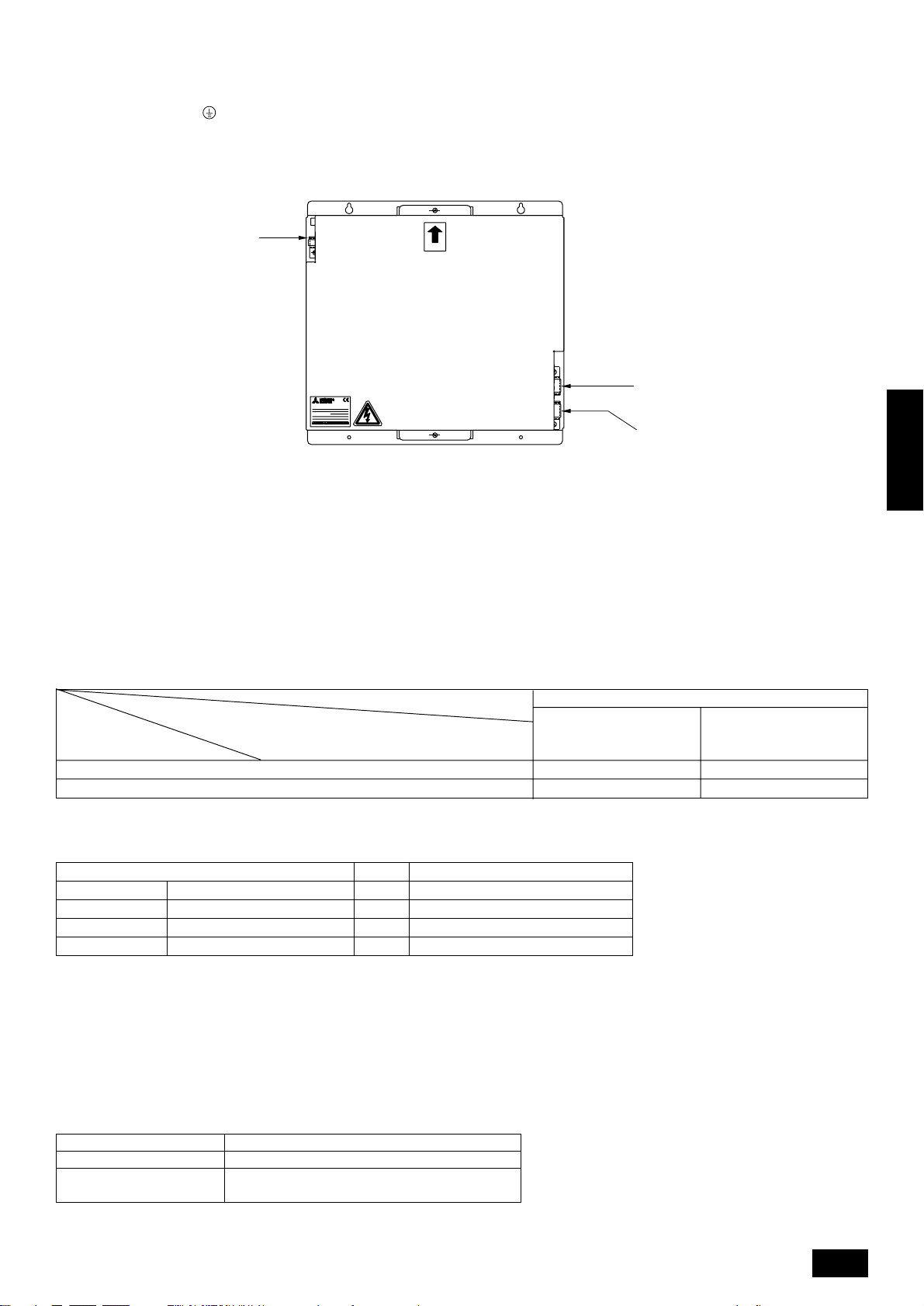
1 Outdoor unit
1. Remove the total of six screws at the top and bottom, and remove
the service panel by pulling it forward. (See the figure below.)
A
A Service panel
ENGLISH
2. Remove the two screws on the left and right-hand of the base of the
control box and pull the overall co ver do wnwards to detach it. (A diagram with the control box cover removed is shown below.)
3. Connect indoor and outdoor units through the terminal block for transmission lines (TB3). Outdoor units and connections to central control
systems go through the terminal block for centralized control (TB7).
When making an indoor/outdoor connection with shielded wiring, connect the shield ground to the shield screw. When making a central
control system connection with shielded wiring, use the terminal block
for centralized control (TB7).
When the CN41 power supply connector of an outdoor unit has been
replaced with a CN40, the shield terminal (S) for centralized control
(TB7) should also be connected to the shield screw.
2 How to use the conduit mounting plate
(1) Conduit mounting plates (ø46, ø53, ø62) are being provided.
Select conduit mounting plate based on the outside diameter of conduit to be used and mount it as shown in the figure.
(2) Fix power source wiring to control box by using buffer bushing for
tensile force (PG connection or the like).
J
B
F
LD1
CD A
E
L1 L2 L3
N
TB1
GHI
A INV board
B MAIN board
C Ten position
D One position
E Address switch
F FANCON board
G Power source
H Shield screw
I Transmission line
J RELAY board
K Shield terminal (S)
M1 M2M1 M2 S
TB7TB3
K
Tensile force
knockout hole
A ø46 mounting hole
B ø53 mounting hole
C ø62 knockout hole
D For the connection of conduit at bottom
E ø62 mounting hole
F For the connection of conduit at front
G The front of outdoor unit
To prevent external tensile force from applying to the wiring connection
section of power source terminal block, use buffer bushing like PG
connection or the like.
3 How to use the wire mounting plate
(1) When the power source and transmission lines are wired through
the knock-out hole of the left wiring, it is necessary to attach the
mounting plate onto the base of the front of the control box with two
screws.
In this case, please use the top clamp to fasten the transmission line
and the lower installation hole to fasten the power supply line.
If it does not match with the outer diameter of the power line conduit,
mount the power line conduit mounting plate (ø46) as shown in the fig-
ure below.
Also, please fasten it so that no tension is brought to bear on the power
line, as shown above.
Control Box
Control Box
ø46 mounting hole
Ø46 mounting hole
Transmission
Transmission
wire
wire
Source wire
Source wire
Wire mounting plate
Wire mounting plate
Front side
Ø53 mounting hole
24
ø53 mounting hole
Front side
Page 25
4 Transmission booster (optional)
Transmission cables
terminal block 2 (TB3)
Transmission cables
terminal block 1 (TB2)
Power terminal
block (TB1)
and Earth
(For details, see item 11.3. “Wiring transmission cables”)
Connect 220/230/240 VAC to L/N of power terminal block (TB1).
Connect the ground to the terminal of power terminal block (TB1).
Connect the outdoor unit side transmission cables to A/B of transmission cables terminal block 1 (TB2).
Connect the outdoor unit side shield to S of transmission cables terminal block 1 (TB2).
Connect additional indoor unit side transmission cables to A/B of transmission cables terminal block 2 (TB3).
Connect additional indoor unit side shield to S of transmission cables terminal block 2 (TB3).
Power terminal
Power terminal
block (TB1)
block (TB1)
and Earth
and Earth
TRANSMISSION BOOSTER
MODEL
PAC-SF46EPA
POWER RATING
WEIGHT
MADE IN JAPAN
220-240V:0.7A ~/N
50
3.4kg
UP
Transmission cables
Transmission cables
terminal block 2 (TB3)
terminal block 2 (TB3)
Transmission cables
Transmission cables
terminal block 1 (TB2)
terminal block 1 (TB2)
11.3. Wiring transmission cables
Wiring method, address setting method and permissible wiring length differ according to and whether or not you are using transmission booster. Chec k
permissible wiring length before wiring.
A may be required depending on the number of indoor units.
Item 4 “Wiring examples” gives typical wiring examples (A – C).
A. System using remote controller (1 outdoor unit)
B. System using remote controller (system operated as a group among multiple refrigerant systems)
C. System using power supply extension unit for transmission booster (combination of systems a – b)
1 Connecting a transmission booster
A transmission booster (RP) is required when the number of connected indoor unit models in a cooling system exceeds the number of models specified
in the chart below.
* The maximum number of units that can be controlled is determined by the indoor unit model, the type of remote controller and their capabilities.
(*1)
Capability of the
connected indoor units
*1 If even one unit that is higher than 200 exists in the cooling system, the maximum capacity will be “200 or higher”.
2 Name, code and possible unit connections
Outdoor unit
Indoor unit
Remote controller
Other
*1 A transmission booster (RP) may be required depending on the number of connected indoor unit controllers.
3 Types of control cables
(1) Wiring transmission cables
• Types of transmission cables
Shielding wire CVVS or CPEVS
• Cable diameter
More than 1.25 mm
• Maximum wiring length within 200 m
(2) Remote control cables
Kind of remote control cable 2-core cable (unshielded)
Cable diameter 0.5 to 0.75 mm
Remarks
4 Wiring examples
Typical wiring examples are shown on pages 26 to 30 (Wiring examples A – C).
Remote controller type
Number of connected indoor units that can be
connected without a RP.
200 or lower
200 or higher
The number of indoor units and the total number of remote controllers is displayed within the parenthesis ( ).
Name Code Possible unit connections
Outdoor unit controller
Indoor unit controller
Remote controller (*1)
Transmission booster unit
2
2
OC
IC
2 to 32 units per 1 OC (*1)
RC
2 units maximum per group
RP
0 to 1 unit per 1 OC (*1)
–
When 10 m is exceeded, use cable with the same
specifications as (1) Transmission line wiring.
ENGLISH
Remote controller PAR-F 25MA
Prior to Ver. E After Ver. F
16 (32) 20 (40)
16 (32) 16 (32)
25
Page 26
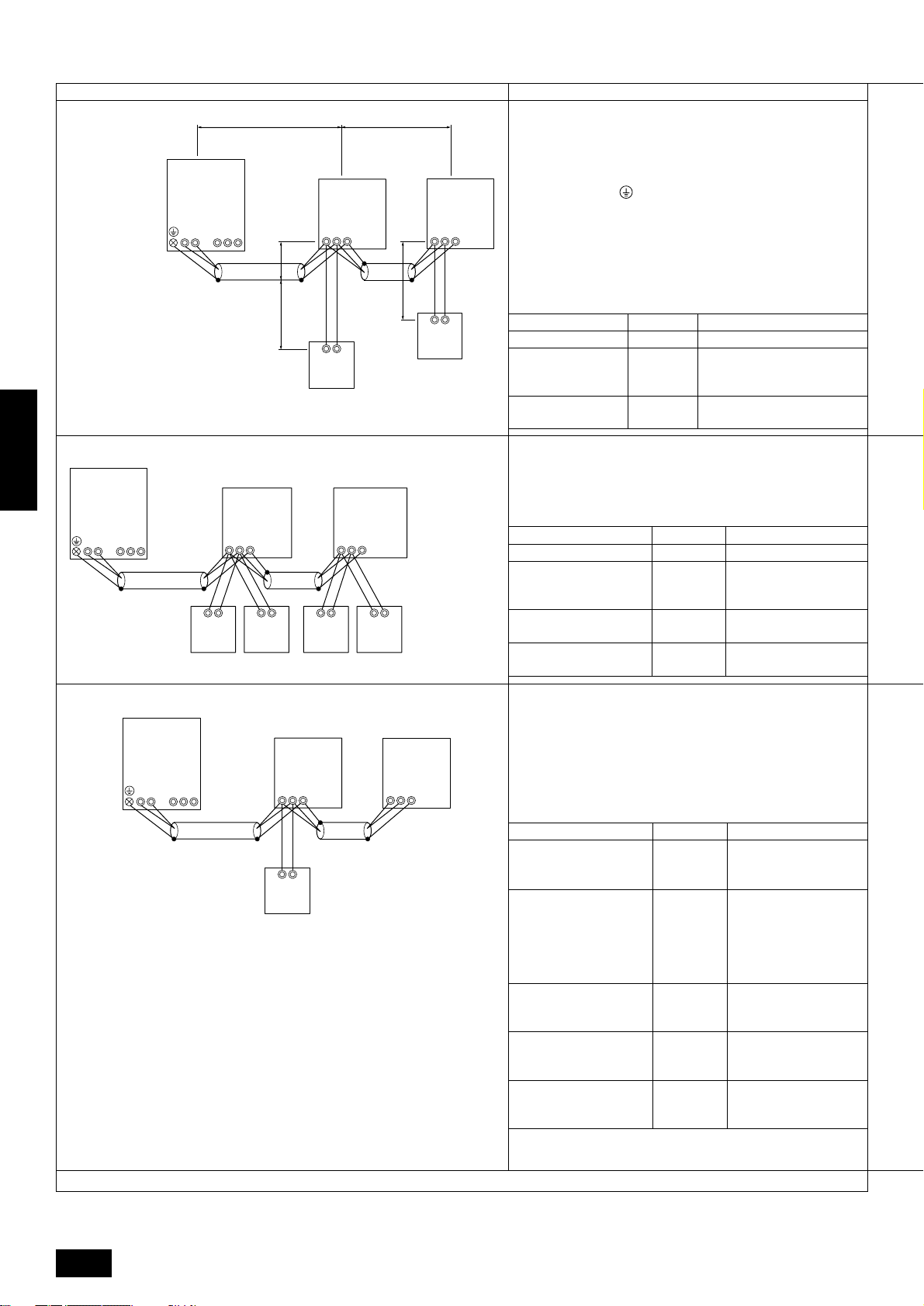
A. Example of a single-outdoor-unit system (Shielding wires and address setting are necessary)
Example of Wiring Control Cables Wiring Method and Address Setting
1. Standard Operation
OC
(51)
TB3 TB7
M1 M2
M1 M2 S
L
1
(01)
TB5
M1 M2 S
3
L
L
2
IC
TB5
M1 M2 S
IC
(02)
a. Use feed wiring to connect terminals M1 and M2 on transmis-
sion cable block (TB3) for the outdoor unit (OC) to terminals
M1 and M2 on the transmission cable block (TB5) of each
indoor unit (IC). Use non-polarized two wire.
To ground the shielded wire, use cross-over wiring from the
ground terminal on the outdoor unit and terminal S on the
indoor unit (TB5).
b. Connect terminals M1 and M2 on the transmission cable block
(TB5) for each indoor unit with the terminal block (TB6) for the
remote controller (RC).
c. Set the address setting switch as shown below.
• One remote controller for each indoor unit.
• Inside ( ) Address: There is no
need for setting the 100 position on
the remote controller.
2
r
1
r
TB6
(102)
TB6
(101)
RC
RC
* To set the outdoor unit address to 100, the outdoor address
setting switch must be set to 50.
Unit
Indoor Unit
Outdoor Unit
Remote Controller
Range
01 to 50
51 to 100
101 to 150
Setting Method
—
Use the most recent
address of all the indoor
units plus 50
Indoor unit address plus
100
2. Operation Using Two Remote controllers
OC
ENGLISH
(51)
TB3 TB7
M1
M2 M1 M2 S
• Using two remote
controllers for
each indoor unit.
3. Group Operation
OC
(51)
TB3 TB7
M1 M2
M1 M2 S
• Operating multiple indoor units
using one remote controller.
M1 M2 S
TB6
(101)
RC
AB AB
TB5
(01)
IC
(151)
TB6
a. Same as above
b. Same as above
IC
c. Set the address switch as shown below.
* To set the outdoor unit address to 100, the outdoor address
setting switch must be set to 50.
Unit
Indoor Unit
Range
01 to 50
Setting Method
—
TB5
M1 M2 S
(02)
Use the most recent
A Main Remote
Outdoor Unit
51 to 100
Controller
TB6
(102)
RC
RC
TB6
(152)
RC
B Sub Remote
Controller
Main Remote Controller
Sub Remote Controller
101 to 150
151 to 200
address of all the indoor
units plus 50
Indoor unit address plus
100
Indoor unit address plus
150
a. Same as above
b. Connect terminals M1 and M2 on transmission cable terminal
A
IC
B
IC
block (TB5) of the IC main unit with the most recent address
within the same indoor unit (IC) group to terminal block (TB6)
on the remote controller.
c. Set the address setting switch as shown below.
* To set the outdoor unit address to 100, the outdoor address
TB5
M1 M2 S
(01)
TB5
M1 M2 S
(02)
setting switch must be set to 50.
Unit
Range
Setting Method
Use the most recent ad-
01 to 50
01 to 50
dress within the same group
of indoor units
Use an address, other than
that of the IC (Main) from
among the units within the
same group of indoor units
TB6
(101)
RC
IC (Main)
IC (Sub)
This must be in sequence
with the IC (Main)
Use the most recent ad-
Outdoor Unit
51 to 100
dress of all the indoor units
plus 50
Set at an IC (Main) address
within the same group plus
100
Set at an IC (Main) address
within the same group plus
150
A Main
B Sub
Main Remote
Controller
Sub Remote
Controller
101 to 150
151 to 200
d. Use the indoor unit (IC) within the group with the most func-
tions as the IC (Main) unit.
Combinations of 1 through 3 above are possible.
26
Page 27
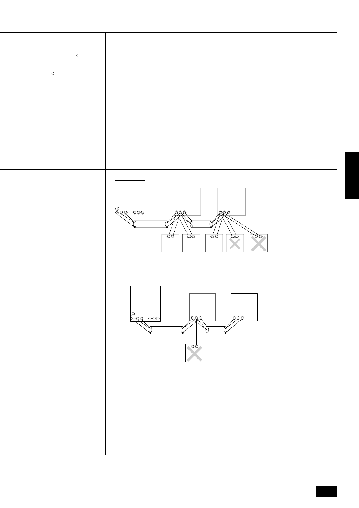
Permissible Lengths Prohibited Items
Longest Transmission Cable Length
(1.25 mm2)
L1 + L2, L2 + L3, L3 + L1 = 200 m
Remote Controller Cable Length
1 If 0.5 to 0.75 mm
2
r1 , r2 = 10 m
2 If the length exceeds 10 m, the
exceeding section should be 1.25
mm2 and that section should be a
value within the total extension
length of the transmission cable
and maximum transmission cable
length (L3).
Same as above
Same as above
OC
(51)
TB3 TB7
M1
M2 M1 M2 S
M1 M2
(51)
OC
TB7TB3
A B S
IC
(01)
TB5
SM1 M2
M1 M2
TB6
(101)
RC
(151)
TB6
(102)
RC
TB6
IC
(02)
TB5
S
TB6
(103)
RC
RC
AB AB
A
TB5
M1 M2 S
IC
(01)
TB5
M1 M2 S
IC
(02)
B
TB6
(104)
RC
• Use the indoor unit
(IC) address plus 150
as the sub remote
controller address. In
this case, it is 152.
• Three or more remote
controllers (RC)
cannot be connected
to one indoor unit.
A Main
B Sub
ENGLISH
TB6
(102)
RC
• The remote controller address is the
indoor unit main
address plus 100. In
this case, it is 101.
A Main
B Sub
Note:
1. If there is one or more 200 or higher indoor units within the same cooling system, and the number of indoor units exceeds 16 units, a
transmission booster is necessary (when a “PAR-F25MA Ver. F” or subsequent version of remote control is used).
2. If there is not even one 200 or higher indoor unit within the same cooling system, and the number of indoor units exceeds 20 units, a
transmission booster is necessary (when a “PAR-F25MA Ver. F” or subsequent version of remote control is used).
* For details, see wire connection example C.
27
Page 28
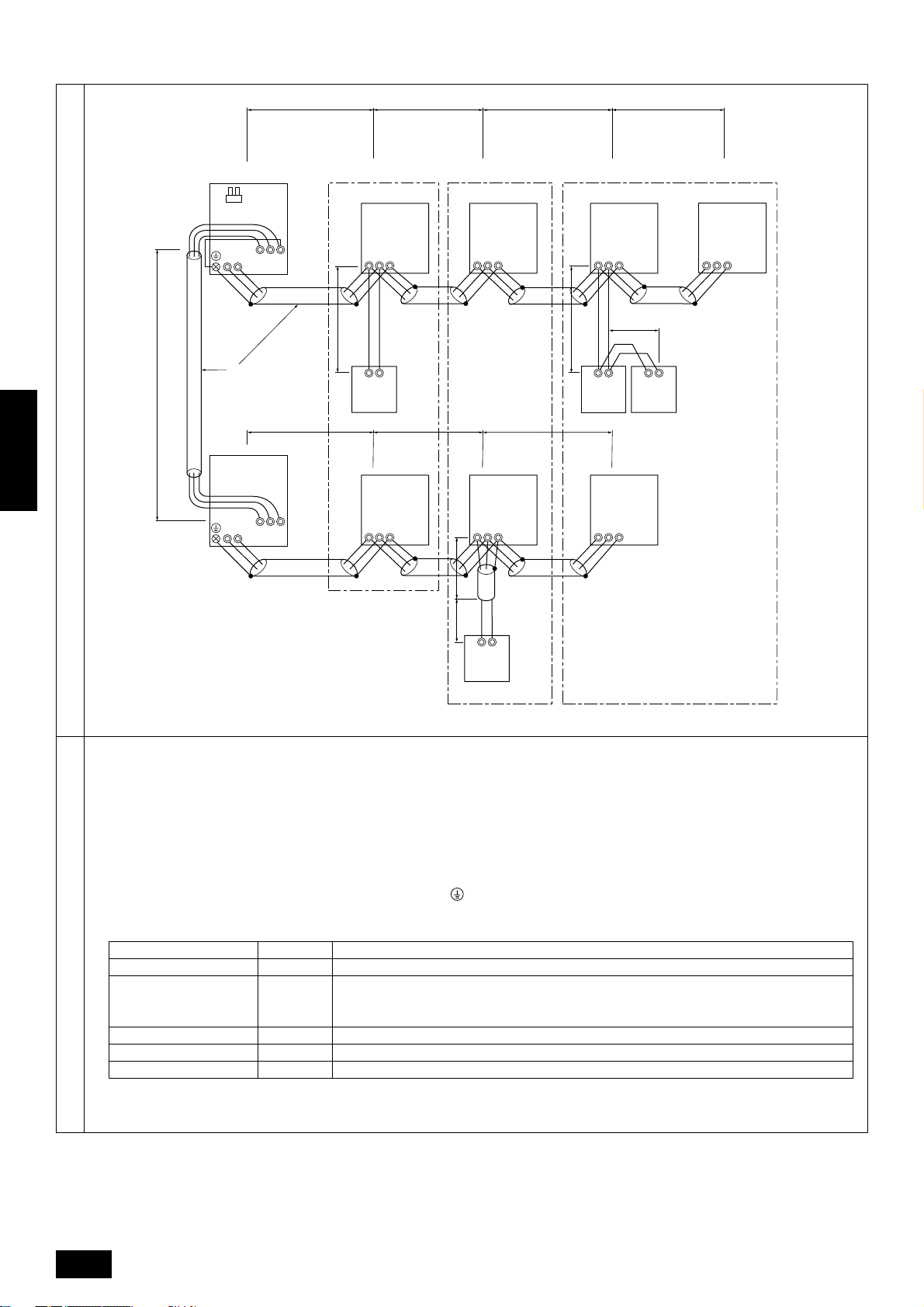
B. Example of a group operation system with multiple outdoor units (Shielding wires and address setting are necessary)
L9
ENGLISH
Example of transmission line wiring
TB3
M1 M2
D
TB3
M1 M2
(51)
(52)
OC
CN40
OC
L1
L2 L3 L4
A B C
IC
(01)
TB5
M1 M2 S
TB7
L5 L6 L7
M1 M2 S
TB7
M1 M2 S
r1
TB6
(101)
RC
IC
(02)
TB5
M1 M2 S
L8
TB5
M1 M2 S
TB5
M1 M2 S
(04)
(03)
IC
r2
TB5
M1 M2 S
TB6
(105)
RC
(05)
IC
r3
TB6
(155)
RC
TB5
M1 M2 S
IC
(06)
E
IC
TB5
M1 M2 S
IC
(07)
A Group 1
B Group 3
C Group 5
D Shielded Wire
E Sub Remote Controller
( ) Address
r4
TB6
(103)
RC
a. Always use shielded wire when making connections between the outdoor unit (OC) and the indoor unit (IC), as well for all OC-OC, and IC-
IC wiring intervals.
b. Use feed wiring to connect terminals M1 and M2 and the ground terminal on the transmission cable terminal block (TB3) of each outdoor
unit (OC) to terminals M1, M2 and terminal S on the transmission cable block of the indoor unit (IC).
c. Connect terminals M1 and M2 on the transmission cable terminal block of the indoor unit (IC) that has the most recent address within the
same group to the terminal block (TB6) on the remote controller (RC).
d. Connect together terminals M1, M2 and terminal S on the terminal block for central control (TB7) for the outdoor unit (OC).
e. On one outdoor unit only, change the jumper connector on the control panel from CN41 to CN40.
f. Connect the terminal S on the terminal block for central control (TB7) for the outdoor unit (OC) f or the unit into which the jumper connector
was inserted into CN40 in Step above to the ground terminal
in the electrical component box.
g. Set the address setting switch as follows.
* To set the outdoor unit address to 100, the outdoor address setting switch must be set to 50.
Unit Range Setting Method
IC (Main) 01 to 50 Use the most recent address within the same group of indoor units
Use an address, other than that of the IC (Main) from among the units within the same group of
IC (Sub) 01 to 50
indoor units
This must be in sequence with the IC (Main)
Wiring method, address setting method
Outdoor Unit 51 to 100 Use the most recent address of all the indoor units plus 50
Main Remote Controller 101 to 150 Set at an IC (Main) address within the same group plus 100
Sub Remote Controller 151 to 200 Set at an IC (Main) address within the same group plus 150
h. The group setting operations among the multiple indoor units is done by the remote controller (RC) after the electrical power has been
turned on.
28
Page 29
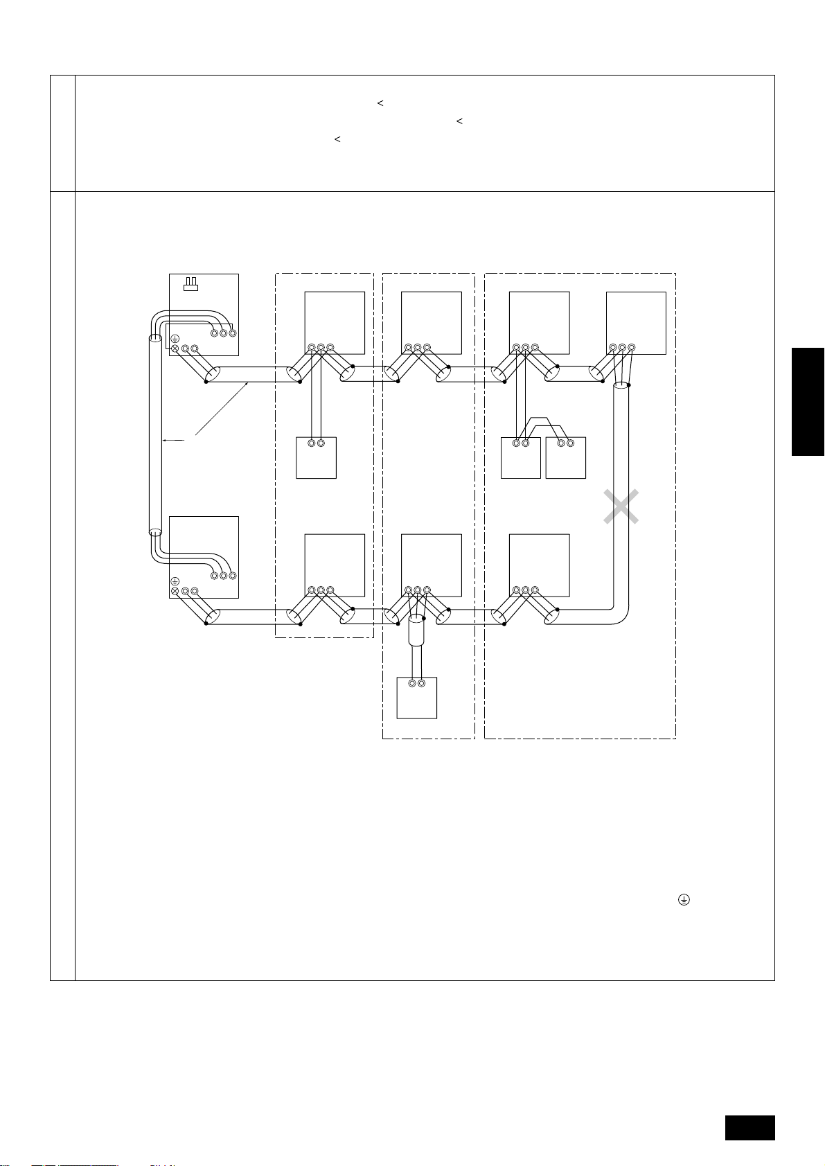
• Max length via outdoor units: L1+L2+L3+L4+L5+L6+L7+L9,
L
1+L2+L3+L4+L5+L6+L8+L9
500 m (1.25 mm2)
=
• Max transmission cable length: L1+L2+L3+L4, L5+L6+L7, L5+L6+L8, L7+L8 = 200 m (1.25 mm2)
• Remote controller wire length: r
Permissible Lengths
1, r2, r3, r4
If the length exceeds 10 m, use a 1.25 mm
in the calculation of the maximum length and overall length.
10 m (0.5 to 0.75 mm2)
=
2
shielded wire. The length of this section (L8) should be included
Prohibited Items
TB3
M1 M2
D
TB3
M1 M2
OC
CN40
(51)
OC
(52)
M1 M2 S
TB7
TB7
A B C
TB5
M1 M2 S
(01)
TB5
M1 M2 S
IC
(05)
IC
TB5
M1 M2 S
IC
(04)
TB5
M1 M2 S
IC
(06)
ENGLISH
TB5
(07)
TB6
(155)
RC
IC
TB6
(101)
RC
TB6
(105)
RC
E
IC
(02)
TB5
SM1 M2
M1 M2 S
TB5
M1 M2 S
IC
(03)
M1 M2 S
TB6
(103)
RC
A Group 1
B Group 3
C Group 5
D Shielded Wire
E Remote Controller
• The terminal S on the terminal block (TB7) for the central control panel should be connected to the ground terminal of the electric
components box of the only outdoor unit installed with the CN40 into which the jumper connector was inserted.
• Never connect together the terminal blocks (TB5) f or transmission wires for indoor units (IC) that ha ve been connected to diff erent outdoor
units (OC).
• Set all addresses to ensure that they are not overlapped.
Note:
1. If there is one or more 200 or higher indoor units within the same cooling system, and the number of indoor units exceeds 16 units, a
transmission booster is necessary (when a “PAR-F25MA Ver. F” or subsequent version of remote control is used).
2. If there is not even one 200 or higher indoor unit within the same cooling system, and the number of indoor units exceeds 20 units, a
transmission booster is necessary (when a “PAR-F25MA Ver. F” or subsequent version of remote control is used).
* For details, see wire connection example C.
29
Page 30
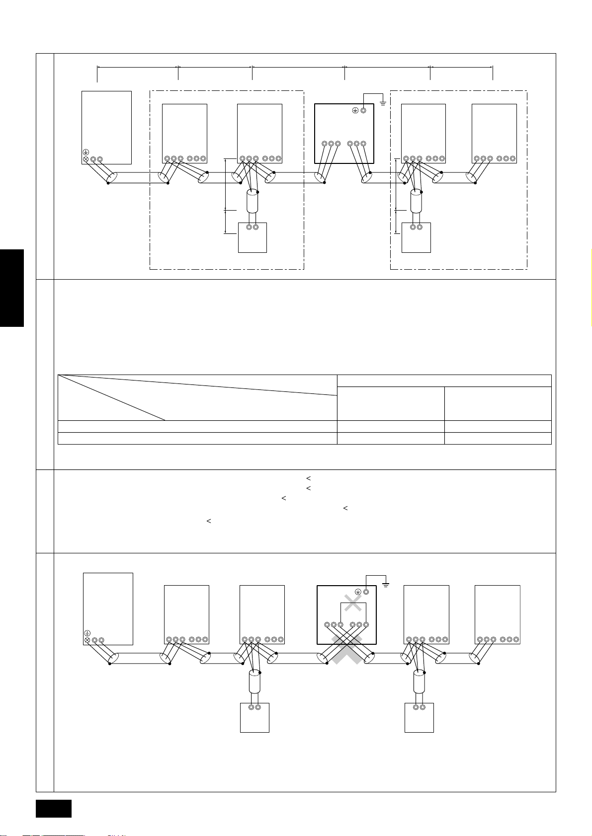
C. Example of a system using the transmission booster (Combination of systems A and B)
L
1
L
2
L
3
L
5
L
6
OC
TB3
M1 M2
Example of transmission line wiring
a. Address settings are the same as for wiring connection examples A and B.
b. Let the number of indoor units and remote control units connected be within the limit for the number of units shown in the following table for
ENGLISH
the total of the number of units connected between the outdoor unit (OC) and the transmission booster (RP) N
connected after the transmission booster (RP) N2.
c. Connect the power supply ground to the transmission booster (RP) securely.
Connect the transmission lines of the outdoor unit side to terminals A and B of transmission line terminal block 1 (TB2) of the transmission
booster (RP).
Connect the transmission lines of the expansion indoor unit side to terminals A and B of the of transmission line terminal block 2 (TB3) of the
transmission booster (RP).
(*1)
Capability of the
connected indoor units
Wiring method, address setting method
*1 If even one unit that is higher than 200 exists in the cooling system, the maximum capacity will be “200 or higher”.
• Indoor system maximum remote wiring length: 1 L1+L2+L3+L5+L6 = 200 m (1.25 mm2)
• Remote control wiring length: r1, r2 = 10 m (0.5 to 0.75 mm2)
Permissible length
Ground
Ground
TB5
M1M2 S
IC
TB13
123
4
L
1
r
TB5
M1M2 S
TB6
RC
IC
123
TB13
RP
TB3
TB2
ABS
ABS
N
1
7
L
1
r
TB5
M1M2 S
TB6
IC
TB13
123
RC
TB5
M1M2 S
1 and the number of units
Remote controller type
Number of connected indoor units that can be
Remote controller PAR-F 25MA
Prior to Ver. E After Ver. F
connected without a RP.
200 or lower
200 or higher
The number of indoor units and the total number of remote controllers is displayed within the parenthesis ( ).
16 (32) 20 (40)
16 (32) 16 (32)
2 L1+L2+L3+L5+L7 = 200 m (1.25 mm2)
3 L1+L2+L4 = 200 m (1.25 mm2)
4 L6+L5+L3+L4, L4+L3+L5+L7 = 200 m (1.25 mm2)
If the length exceeds 10 m, use 1.25 mm2 shielded cable and calculate the length of that portion (L4 and L7)
as within the total extended length and the longest remote length.
IC
123
TB13
N
2
TB3
M1 M2
OC
TB5
M1M2 S
IC
123
TB13
TB5
M1M2 S
IC
TB13
123
RP
TB2
AB S
TB3
AB S
Ground
Ground
TB5
M1M2 S
IC
123
TB13
TB5
M1M2 S
IC
123
TB13
Prohibited items
TB6
RC
TB6
RC
• Do not mistake the connection locations of transmission booster (RP) transmission line terminal block 1 (TB2) and transmission line
terminal block 2 (TB3). (Operation will not be normal in such a case.)
• Do not connect the S terminals of transmission line terminal block 1 (TB2) and transmission line terminal block 2 (TB3) of the transmission
booster (RP) together.
30
Page 31

11.4. Wiring of main power supply and equipment capacity
Warning:
• Be sure to use specified wires to connect so that no external force is imparted to terminal connections. If connections are not fixed firml y ,
it may cause heating or fire.
• Be sure to use the appropriate type of overcurrent protection s witch. Note that generated o vercurrent may inc lude some amount of direct
current.
Caution:
• The reverse phase of L lines (L1, L2, L3) can be detected (Error cord : 4103), but the reverse phase of L lines and N line can be not be
detected.
- The some electric parts should be damaged when power is supplied under the miss wiring.
• Some installation site may require attachment of an earth leakage breaker. If no earth leakage breaker is installed, it ma y cause an electric
shock.
• Do not use anything other than breaker and fuse with correct capacity. Using fuse and wire or copper wire with too large capacity may
cause a malfunction of unit or fire.
Schematic Drawing of Wiring (example)
ENGLISH
A Power Supply (3-Phase, 4-Wire) 380/400/415 Volt
B Switch
C Outdoor Unit
D Ground
Thickness of Wire for Main Power Supply and On/Off Capacities (example)
Switch (A)Minimum Wire Thickness (mm2)
Wiring (NFB)
63
63
20 A
Model
PUHY-P400
PUHY-P500
Outdoor Unit
Model
All Models
Indoor Unit
Main Cable
10.0
16.0
Wire Thickness (mm2)
Main
Cable
1.5
Branch
1.5
Branch
–
–
Ground
1.5
Ground
10.0
16.0
Switch (A)
Capacity
Capacity
63
63
Fuse
1616
Fuse
Breaker for
Wiring (NFB)
E Power Supply (Single-Phase) 220/230/240 Volt
F 1.5 mm2 or more
G Pull Box
H Indoor Unit
Breaker for
75 A
Breaker for Current Leakage
Breaker for Current Leakage
75 A 100 mA 0.1 s. or less
20 A 30 mA 0.1 s. or less
1. Use a separate power supply for the outdoor unit and indoor unit.
2. Bear in mind ambient conditions (ambient temperature,direct sunlight, rain water,etc.) when proceeding with the wiring and connections.
3. The wire size is the minimum value for metal conduit wiring. The power cord size should be 1 rank thicker consideration of v oltage drops.
Make sure the power-supply voltage does not drop more than 10%.
4. Specific wiring requirements should adhere to the wiring regulations of the region.
5. Power supply cords of parts of appliances for outdoor use shall not be lighter than polychloroprene sheathed flexible cord (design 245
IEC57). For example, use wiring such as YZW.
31
Page 32

12. Test run
D
12.1. Checking before getting test run
1 Check to see whether there are refrigerant leakage, and slack of power or transmission cable.
Confirm that 500 V megger shows 1.0 MΩ or more between power supply terminal block and ground. Do not operate in the case of 1.0 MΩ or less.
2
NOTE:Never carry out megohm check over terminal control board. Otherwise the control board would be broken.
Immediately after mounting the unit or after leaving it turned off for an extended length of time, the resistance of the insulation between the
power supply terminal board and the ground may decrease to approx. 1 MΩ as a result of refrigerant accumulating in the internal compressor.
If the insulation resistance is more than 1 MΩ, turning on the main power supply and energizing the crankcase heater for more than 12
hours will cause the refrigerant to evaporate, increasing the insulation resistance.
Check to see whether both gas and liquid valves are fully open.
3
NOTE: Be sure to tighten caps.
Check the phase sequence and the voltage between phases.
4
NOTE:If the phase sequence is reversed, an error (4103) may occur when a test run is made, causing the unit to stop.
If a transmission booster is connected:
5
Turn transmission booster power on the before turning the outdoor unit’s pow er on.
NOTE 1: If the outdoor unit’s pow er is turned on first, refrigerant system connection data may not be recognized normally.
NOTE 2: If the outdoor unit’s pow er is turned on first, reset the outdoor unit’s power after turning the transmission booster power on.
T urn on universal pow er supply at least 12 hours before getting test run in order to carry current to crank case heater . If current-carrying hours are
6
too short, it may result in a malfunction of compressor.
12.2. Test run method
ENGLISH
E
–
ON/OFF
ON OFF
ON OFFCLOCK
1Hr.
NOT AVAILABLE
˚C
FILTER
CHECK MODE
TEST RUN
FILTER
CHECK
TEST RUN
A
B
CENTRALLY CONTROLLED
STAND BY
DEFROST
REMOTE CONTROLLER
PAR-F25MA
CHECK
˚C
INDOOR UNIT
ADDRESS NO
TEMP. TIMER SET
CLOCK
ERROR CODE
OA UNIT ADDRESS NO
C
A Display panel
B Control panel
C Cooling/Heating select button 3, 4
D Check code indicator (see note 1)
E Test run remaining time indicator (see note 3)
F ON/OFF LED (Lights up in operation)
Operation procedure
1 Turn on universal power supply at least 12 hours bef ore getting started → Displaying “HO” on display panel for about two minutes. The universal
power supply must be left on for at least 12 hours (with the crank case heater turned on). If a transmission booster is connect ed, turn transmission
booster power on the before turning the outdoor unit’s power on.
2 Press [TEST RUN] button twice → Displaying “TEST RUN” on display panel.
3 Press [Cooling/Heating] select button → Make sure that air is blowing out.
Press [Cooling/Heating] select button to change from cooling to heating operation, and vice versa → Make sure that warm or cold air is blowing
4
out.
5 Press [Wind] adjust button → Make sure that air blow is changed.
6 Press [Up/Down Wind] or [Louver] button to change wind → Make sure that horizontal or downward blow is adjustable.
7 → Make sure that indoor unit fans operate normally.
8 Make sure that interlocking devices such as ventilator operate normally if any.
9 Press [ON/OFF] button to cancel test run → Stop operation.
NOTE 1: If check code is displayed on remote controller or remote controller does not operate normally, see page 33 or further.
NOTE 2: Test run automatically stops operating after two hours by activation of timer set to two hours.
NOTE 3: During test run, test run remaining time is displayed on time display section.
NOTE 4: During test run, temperature of liquid pipe in indoor unit is displayed on remote controller room temp. display section.
NOTE 5: When pressing [Wind] adjust button, depending on the model, “This function is not available” may be displayed on remote controller.
However, it is not a malfunction.
G Indoor unit liquid pipe temperature indicator (See note 4)
H ON/OFF button 9
I Test run indicator
J Wind adjust button 6
K Test run button 2
L Air blow adjust button 5
F
G
H
I
J
K
L
32
Page 33

12.3. How to cope with test run abnormality
1 A 4-digit check code is displayed on remote controller display panel if unit is stopped due to an abnormality. Check to see causes of that
abnormality.
1. Indoor unit
Check code Check Content Check code Check Content
2500 Leakage (water) abnormality
2502 Drain pump abnormality
2503 Drain sensor abnormality
4116 Fan speed abnormality (motor abnormality)
5101 Air inlet (TH21)
5102 Liquid pipe (TH22)
5103 Gas pipe (TH23)
6600 Multiple address abnormality
2. Outdoor unit
Check code Check Content Check code Check Content
0403 Serial transmission abnoramlity
1102 Discharge temperature abnormality
1111 Low pressure saturation temperature sensor
1112
1113
1301 Low pressure abnormality
1302 High pressure abnormality
1500 Overcharged refrigerant abnormality
1501 Low refrigerant abnormality
1505 Suction pressure abnormality
4103 Reverse phase abnormality
4108 Overcurrent protection (51C2)
4115 Power supply sync signal abnormality
4200 VDC sensor/circuit abnormality
4210 Breaking of overcurrent
4220 Bus voltage abnormality
4230 Radiator panel overheat protection
4240 Overcurrent protection
4260 Cooling fan abnormality
Thermal sensor
abnormality
abnormality (TH2)
Low pressure
saturation
temperature
abnormality
Liquid level sensing temperature
sensor abnormality (TH4)
Liquid level sensing temperature
sensor abnormality (TH3)
6602 Transmission processor hardware abnormality
6603 Transmission circuit bus-busy abnormality
6606
6607 No ACK abnormality
6608 No response abnormality
7101 Capacity code abnormality
7111 Remote control sensor abnormality
5101 Discharge (TH1)
5102 Low pressure saturation (TH2)
5103 Accumulater liquid level (TH3)
5104 Accumulater liquid level (TH4)
5105 Liquid pipe (TH5)
5106 Ambient temperature (TH6)
5107 SC coil outlet (TH7)
5108 SC coil bypass outlet (TH8)
5109 SC coil bypass inlet (TH9a)
5110 Radiator panel
5114 Compressor shell temperature (TH10)
5201 Pressure sensor abnormality
5301 IDC sensor/circuit abnormality
6600 Multiple address abnormality
6602 Transmission processor hardware abnormality
6603 Transmission circuit bus-busy abnormality
6606
6607 No ACK abnormality
6608 No response abnormality
7100 Total capacity abnormality
7101 Capacity code abnormality
7102 Connected unit count over
7105 Address setting abnormality
Communications with transmission processor abnormality
Thermal sensor
abnormality
CS circuit liquid temperature (TH9b)
Communications with transmission processor abnormality
ENGLISH
33
Page 34

3. Remote controller
Check code Check Content Check code Check Content
6101 Unreadable response receiving error
6600 Multiple address abnormality
6602 Transmission processor hardware abnormality
6606
Communications with transmission processor abnormality
6607 SC coil outlet (TH7)
6608 SC coil bypass outlet (TH8)
6603 Transmission circuit bus-busy abnormality
2 Diagnostic switch (SW1) and the service LED on multi-controller board of indoor unit can be used to judge a malfunction of outdoor unit.
<Operation of self-diagnosis switch (SW1) and the service LED display>
Self-diagnosing
item
Relay output
display 1
(Lighting)
Check
display 1
a
(Blinking)
Relay output
display 2
ENGLISH
Check
indoor unit
Indoor unit
mode
b
SW1 setting
A
B
1234567 8910
A
B
1234567 8910
A
B
1234567 8910
A
B
1234567 8910
A
B
1234567 8910
A
B
1234567 8910
A
B
1234567 8910
A
B
1234567 8910
C
Display at LED lighting (blinking)
Flag 1 Flag 2 Flag 3 Flag 4 Flag 5 Flag 6 Flag 7 Flag 8
During
compres-
sor run
Compres-
operations
sor 1
Compres-
sor 2
operations
21S4
SV1
SV22/32
Always
lighting
0000 to 9999 (Alternate display of address and error code)
SV4
No.1
unit
No.9
unit
No.17
unit
No.1
unit
No.9
unit
No.17
unit
21S4b
No.2
unit
No.10
unit
No.18
unit
No.2
unit
No.10
unit
No.18
unit
SV5b
No.3
unit
No.11
unit
No.19
unit
No.3
unit
No.11
unit
No.19
unit
SV6
No.4
unit
No.12
unit
No.20
unit
No.4
unit
No.12
unit
No.20
unit
CH2, 3
No.5
unit
No.13
unit
No.5
unit
No.13
unit
52F
No.6
unit
No.14
unit
No.6
unit
No.14
unit
No.7
unit
No.15
unit
No.7
unit
No.15
unit
No.8
unit
No.16
unit
No.8
unit
No.16
unit
Remarks
Flag 8 always lights
at microcomputer
power ON
21S4b and SV5b are
closed with flag 1
Lights at emergency
stop in IC
Turns off by resetting
Lights at cooling
Blinks at heating
Turns off at stop/fan
A
B
1234567 8910
Indoor unit
thermostat
A
B
1234567 8910
A
B
1234567 8910
Indoor unit
address
a Outdoor unit b Indoor unit
A ON B OFF C At factory shipment
A
B
1234567 8910
No.1
unit
No.9
unit
No.17
unit
No.2
unit
No.10
unit
No.18
unit
No.3
unit
No.11
unit
No.19
unit
Displays in order the addresses (1 through 50) of all indoor units connected to
the outdoor unit.
No.4
unit
No.12
unit
No.20
unit
No.5
unit
No.13
unit
No.6
unit
No.14
unit
No.7
unit
No.15
unit
No.8
unit
No.16
unit
Lights at thermostat
on
Turns off at thermostat off
34
Page 35

Displaying the service LED
ABCDEFGH
Service LED (LD1)
• Error code display
Alternate display of error generating address and error code
Example At outdoor unit address 51, abnormal discharge temperature (Code 1102)
• Flag display
Example SV1 ON under only compressor 1 operated
12.4. Coping with remote controller abnormality
A Flag 1 E Flag 5
B Flag 2 F Flag 6
C Flag 3 G Flag 7
D Flag 4 H Flag 8
Phenomenon
Unit does not operate and
display stays off even after
pressing remote controller
ON switch.
1
(Current-carrying indicator
does not light up)
“HO” indicator does not disappear. Unit does not operate even if the switch is
2
pressed.
Display comes on once but
3
disappears immediately after
a press of the switch.
ON OFF
CLOCK
˚C
ERROR CODE
OA UNIT ADDRESS NO
TEMP. TIMER SET
1Hr.
NOT AVAILABLE
ON OFFCLOCK
CENTRALLY CONTROLLED
STAND BY
DEFROST
REMOTE CONTROLLER
PAR-F25MA
CHECK
INDOOR UNIT
ADDRESS NO
Cause
(1) Outdoor unit power was not turned on.
(2) T r ansmission or remote controller cable
was shorted or connection failure.
(3) Power cable contact failure.
(4) Remote controller was erroneously con-
nected to unit remote controller termi-
nal block.
(5) Too many remote controllers or indoor
units were connected.
(1) No transmission cable was connected
to transmission cable terminal block on
the indoor unit.
(2) Outdoor unit address was erroneously
set.
(3) Indoor unit address was erroneously
set.
(1) Indoor unit power was not turned on.
–
ON/OFF
˚C
FILTER
CHECK MODE
TEST RUN
A
FILTER
CHECK
TEST RUN
A Display: Appears when current is carried
How to cope with abnormality
(a) Check voltage between remote controller terminals.
(i) Remote controller fails when voltage is 17 to 30 V.
(ii) If there is no voltage
• Check the number of remote controllers and indoor units connected.
• Remove wire from transmission cable terminal block (TB3) on
outdoor unit, and check voltage between terminals.
• If voltage is 17 to 30 V, check (2) and (4) at left.
• If there is no voltage, check (1) and (3) at left.
• Check all items at left.
• Check item at left.
ENGLISH
35
Page 36

12.5. The following phenomena do not represent abnormality (emergency)
Phenomenon
Indoor unit does not the perform cooling (heating) operation.
The auto vane runs freely.
Fan setting changes during heating.
Fan stops during heating operation.
Fan does not stop while operation has
been stopped.
No setting of fan while start SW has
been turned on.
Outdoor unit does not operate by turning switch on.
Indoor unit remote controller shows
ENGLISH
“HO” indicator for about two minutes
when turning ON universal power supply.
Drain pump does not stop while unit has
been stopped.
Drain pump continues to operate while
unit has been stopped.
Display of remote controller
“Cooling (heating)” flashes
Normal display
Normal display
Defrost display
No lighting
Heat ready
Normal display
“HO” flashes
Light out
Cause
When another indoor unit is performing the heating (cooling) operation, the cooling (heating) operation is not performed.
Because of the control operation of auto vane, it may change over to
horizontal blow automatically from the downward blow in cooling in case
the downward blow operation has been continued for 1 hour. At defrosting in heating, hot adjusting and thermostat OFF, it automatically
changes over to horizontal blow.
Ultra-low speed operation is commenced at thermostat OFF.
Light air automatically changes over to set value by time or piping temperature at thermostat ON.
The fan is to stop during defrosting.
Fan is to run for 1 minute after stopping to exhaust residual heat (only
in heating).
Ultra low-speed operation for 5 minutes after SW ON or until piping
temperature becomes 35°C, low speed operation for 2 minutes thereafter, and then set notch is commenced. (Hot adjust control)
When the outdoor unit is being cooled and the refrigerant is resting,
warming up operation is performed for at least 35 minutes to warm the
compressor.
During this time, only the fan operates.
System is being driven.
Operate remote controller again after “HO” disappear.
After a stop of cooling operation, unit continues to operate drain pump
for three minutes and then stops it.
Unit continues to operate drain pump if drainage is generated, even
during a stop.
36
Page 37

ENGLISH
37
Page 38

Inhalt
1. Sicherheitsvorkehrungen .......................................................... 39
1.1. Vor Installations- und Elektroarbeiten........................... 39
1.2. Vorsichtsmaßnahmen für Vorr ichtungen,
die das Kältemittel R407C verwenden ......................... 40
1.3. Vor der Aufstellung ....................................................... 40
1.4. Vor dem Einbau (der Ortsveränderung)
- Elektroarbeiten ........................................................... 40
1.5. Vor Installationsbeginn ................................................. 40
2. Kombination mit Innenaggregaten............................................ 41
3. Überprüfung des Lieferumfangs ............................................... 41
4. Kombination mit Außenanlagen ................................................ 42
5. Wahl des Aufstellplatzes ........................................................... 42
6. Vorgeschriebener Freiraum um das Aggregat .......................... 42
6.1. Einzeleinbau ................................................................. 42
6.2. Einbau mehrerer Klimaanlagen und fortlaufender
Einbau .......................................................................... 43
7. Hebemethode und Gewicht der Klimaanlage ........................... 44
8. Einbau der Klimaanlage............................................................ 44
8.1. Lage der Ankerschraube .............................................. 44
8.2. Einbau .......................................................................... 45
8.3. Anschlußrichtung für Kältemittelleitung ........................ 46
8.4. Geräuschpegel ............................................................. 46
9. Schutzvorkehrungen gegen Schnee und starken Wind............ 47
9.1. Schnee und starker Wind ............................................. 47
9.2. Schutzmaßnahmen gegen starken Wind ..................... 47
10. Installation der Kältemittelleitungen......................................... 47
DEUTSCH
10.1. Gefahrenbereiche ....................................................... 48
10.2. Das Kältemittel Rohrsystem........................................ 49
10.3. Vorsichtsmaßregeln für Rohranschluß/Ventilbetrieb ... 51
10.4. Wie eine Rohrverteilung installiert wird ....................... 52
10.5. Test auf Luftdichtigkeit und Luftabsaugung,
Füllen mit Kältemittel................................................... 54
10.6. Kältedämmung und Kältemittelleitung......................... 57
11 . Elektrische Arbeiten................................................................. 59
11.1. Vorsicht ....................................................................... 59
11.2. Reglerkasten und Kabelanschlußpunkte .................... 60
11.3. Übertragungskabelanschluß ....................................... 61
11.4. Verdrahtung der Hauptspannungsversorgung
und Kapazität der Einheiten ........................................ 67
12. Testbetrieb ............................................................................... 68
12.1. Überprüfung vor Beginn des Testbetriebs ................... 68
12.2. Testbetriebsmethode................................................... 68
12.3. Umgang mit Problemen bei Probelänfen .................... 69
12.4. Umgang mit Abnormalitäten der Fernbedienung ........ 71
12.5. Die nachstehenden Erscheinungen stellen keine
Abnormalität (keinen Notfall) dar................................. 72
38
Page 39

1. Sicherheitsvorkehrungen
1.1.
Vor Installations- und Elektroarbeiten
s
V or dem Einbau der Anlage vergewissern, daß Sie alle Infor mationen über “Sicherheitsvorkehrungen” gelesen haben.
s
Die “Sicherheitsvorkehrungen” enthalten sehr wichtige
Sicherheitsgesichtspunkte. Sie sollten sie unbedingt befolgen.
s Diese Anlage ist unter Umständen nicht geeignet für
EN61000-3-2 :1995 und EN61000-3-3: 1995.
s Die Anlage kann negative Aus wirkungen auf ein gleich-
artiges Versorgungssystem haben.
V or Anschluß an das System Mitteilung an Stromversorgungs-
s
unternehmen machen oder dessen Genehmigung einholen.
Im Text verwendete Symbole
Warnung:
Beschreibt Vorkehrungen, die beachtet werden sollten, um den
Benutzer vor der Gefahr von Verletzungen oder tödlicher Unfälle
zu bewahren.
Vo rsi cht :
Beschreibt Vorkehrungen, die beachtet wer den sollten, um die Anlage vor Schäden zu bewahren.
Innerhalb der Abbildungen verwendete Symbole
: Verweist auf eine Handlung, die unterbleiben muß.
: Verweist auf wichtige Anweisungen, die befolgt werden müssen.
: Verweist auf ein Teil, das geerdet werden muß.
:
Zeigt an, daß bei rotierenden Teilen Vorsichtgeboten ist. (Dieses
Symbol findet sich als Aufkleber auf der Hauptanlage). <F arbe: gelb>
: Zeigt an, daß vor Beginn der Wartungsarbeiten der Hauptschalter
ausgeschaltet werden muß. (Dieses Symbol befindet sich als
Aufkleber auf der Hauptanlage). <Farbe: blau>
: Gefahr von elekt rischem Schlag. (Dieses Symbol findet sich als
Aufkleber auf der Hauptanlage). <Farbe: gelb>
: Verbrennungsgefahr (Dieses Symbol befindet sich als Aufkleber
auf der Hauptanlage.) <Farbe: gelb>
:
Bitte äußerste V orsicht v or Stromschlägen, da dies kein Sicherheits-
ELV
stromkreis mit besonders niedriger Spannung (SELV) ist.
Und bei der Wartung bitte Netzstrom sowohl für die Innenals auch für die Außenanlage abschalten.
Warnung:
Die auf der Hauptanlage angebrachten Aufkleber sorgfältig lesen.
Warnung:
• Bitten Sie Ihren Fachhändler oder einen geprüften Fachtechniker ,
die Installation der Anlage vorzunehmen.
- Unsachgemäße Installation durch den Benutzer kann Wasseraus-
tritt, Stromschläge oder Brände verursachen.
• Die Anlage an einer Stelle anbringen, die das Gewicht tragen kann.
- Bei ungenügender Tragkraft kann das Gerät herunterfallen und
Verletzungen verursachen.
• Zur Verdrahtung die angegebenen Kabel verwenden. Die Anschlüsse so sichern, daß Zugspannung von außen nicht auf die
Klemmen wirken kann.
- Falscher Anschluß und falsche Befestigung führen zu Wärme-
bildung und verursachen Brände.
• Vorkehrungen gegen Stürme, starke Luftströme und Erdbeben
treffen und die Anlage an einem Ort aufstellen, der die beschriebenen Bedingungen erfüllt.
- Durch unsachgemäße Installation kann die Anlage herunterfallen
und Verletzungen verursachen.
• Stets Luftreiniger, Luftbefeuchter, Elektroheizungen und sonstige, von Mitsubishi angegebene, Zubehöreinrichtungen verwenden.
- Einen geprüften Techniker bitten, die Zusatzeinrichtungen zu in-
stallieren. Unsachgemäße Installation durch den Benutzer kann
zu Wasseraustritt, Stromschlägen oder Bränden führen.
• Die Anlage niemals selbst reparieren. Wenn die Anlage repariert werden muß, wenden Sie bitte sich an den Fachhändler.
- Wenn die Anlage unsachgemäß repariert wird, kann dies zu Wasser-
austritt, Stromschlägen oder Bränden führen.
• Nicht die Wärmetauscherleitung berühren.
- Unsachgemäße Handhabung kann zu Verletzungen führen.
• Wenn Kältemittelgas während der Installationsarbeiten austritt,
den Raum gründlich lüften.
- Wenn das Kältemittelgas auf offenes Feuer trifft, wird giftiges Gas
freigesetzt.
• Die Anlage gemäß Anweisungen in diesem Installationshandbuch installieren.
- Bei unsachgemäßer Installation kann dies zu W asseraustritt, Strom-
schlägen oder Bränden führen.
• Elektroarbeiten durch einen zugelassenen Fachelektriker in Übereinstimmung mit dem “Electric Facility Engineering Standard” (Technische Normen für Elektr oeinrichtungen), den “Interior Wire
Regulations” - (Vorschriften zur Innenverdrahtung) und den in
diesem Handbuch gegebenen Anweisungen vornehmen. Anlage
auch immer an einen gesonderten Stromkreis anschließen.
- Wenn die Leistung der Stromquelle ungenügend ist oder die
Elektroarbeiten unsachgemäß ausgeführt wurden, kann dies zu
Stromschlägen und zu Bränden führen.
• Die Abdeckung der Elektroanschlüsse der Außenanlage (Abdeckplatte) fest anbringen.
- Wenn die Abdeckung der Elektroanschlüsse (Abdeckplatte) nicht sach-
gemäß angebracht wurde, kann Staub oder W asser in die Außenanlage eindringen und Brände oder Stromschläge verursachen.
• Beim V erbringen der Anlage an einen anderen Standort, Anlage
nicht mit einem anderen Kältemittel als dem auf der Anlage angegebenen Kältemittel (R407C) füllen.
- Wenn das ursprüngliche Kältemittel mit einem anderen Kältemittel
oder mit Luft vermischt wird, kann dies zu Fehlfunktionen des Kältemittelkreislaufs führen und die Anlage beschädigt werden.
• Wenn die Anlage in einem kleinen Raum installiert wird, müssen Maßnahmen ergriffen werden, damit die Kältemittelkonzentration auch bei Kältemittelaustritt den Sicherheitsgrenzwert nicht überschreitet.
- Befragen Sie einen Fachhändler bezüglich geeigneter Maßnah-
men zur Verhinderung des Überschreitens des Grenzwertes. Sollte durch Austreten von Kältemittel das Überschreiten des Grenzwertes erfolgen, besteht wegen möglichem Sauerstoffmangel im
Raum Gesundheitsgefahr.
• Beim Verbringen der Anlage an einen anderen Ort einen Fachhändler oder einen geprüften Techniker zur Neuaufstellung hinzuziehen.
- Bei unsachgemäßer Installation der Anlage kann Wasser austre-
ten, und es können Stromschlage oder Brände verursacht werden.
• Nach Abschluß der Installationsarbeiten sicherstellen, daß kein
Kältemittelgas austritt.
- Wenn Kältemittelgas austritt und mit einem Heizgebläse, einem
Ofen oder sonstigen Wärmequellen in Berührung kommt, kann giftiges Gas erzeugt werden.
• Die Einstellungen der Schutzvorrichtungen nicht neu einrichten oder ändern.
- Wenn Druckschalter , Thermoschalter oder eine andere Schutzvor-
richtung kurzgeschlossen oder mit Gewalt betätigt wird oder wenn
andere als die von Mitsubishi Electric angegebenen Teile verwendet werden, besteht Brand- oder Explosionsgefahr.
•
Zum Entsorgen dieses Gerätes wenden Sie sich an Ihren Fachhändler .
• Der Installateur und der Systemfachmann müssen für die Sicherung gegen W asseraustritt gemäß den örtlichen Bestimmungen und Normen sorgen.
- Falls keine örtlichen Bestimmungen bestehen, sind die nach-
stehenden Normen anzuwenden.
• Besondere Beachtung ist den örtlichen Verhältnissen wie etwa
dem Kellergeschoß etc. zu schenken, wo sich Kältemittelgas
ansammeln kann, da Kältemittel schwerer als Luft ist.
39
DEUTSCH
Page 40

1.2.
Vorsichtsmaßnahmen für Vorrichtungen,
die das Kältemittel R407C verwenden
Vo rsi cht :
• Kältemittel und Öl
- Das alte Kältemittel und das Kältemaschinenöl in der vorhandenen Rohrleitung enthalten große Mengen Chlor, was zur Qualitätsminderung des Kältemaschinenöls der neuen Anlage führen kann.
• Kältemittelrohrleitungen aus phosphor-deoxidiertem Kupfer
C1220 (CU-DHP) gemäß Angaben in JIS H3300 „Nahtlose Rohrleitungen und Rohre aus Kupfer und Kupferlegierung“ verwenden. Außerdem ver gewissern, daß die Innen- und Außenflächen
der Rohrleitungen sauber und frei von gefährlichem Kupfer,
Oxyden, Staub/Schmutz, Metallbearbeitungsrückständen, Ölen,
Feuchtigkeit oder anderen Verunreinigungen sind.
- Verunreinigungen auf der Innenseite der Kältemittelrohrleitungen
können dazu führen, daß das Kältemittelrestöl verdirbt.
• Die bei der Installation verwendete Rohrleitung in einem geschlossenen Raum aufbewahren und beide Enden bis unmittelbar vor dem Hartlöten geschlossen halten. (Krümmer und andere Rohrverbinder in einem Kunststoffbeutel aufbewahren).
-
Wenn Staub, Schmutz oder Wasser in den Kältemittelkreislauf gelangt, kann
dies zu einer Qualitätsminderung des Öls und zu Kompressorstörungen führen.
•
Zum Beschichten der Konus- und Flanschanschlüsse Esteröl/Ätheröl
oder Alkylbenzol (kleine Menge) als Kältemaschinenöl verwenden.
-
Das Kältemaschinenöl zersetzt sich, wenn es mit größeren Mengen
Mineralöl vermischt wird.
• Zur Füllung des Systems flüssiges Kältemittel verwenden.
-
Wenn Kältemittelgas zur Füllung des Systems verwendet wird, ändert sich die
Zusammensetzung des Kältemittels im Zylinder, so daß die Leistung abfallen kann.
• Kein anderes Kältemittel als R407C verwenden.
- Bei Verwendung eines anderen Kältemittels (R22 etc.) kann das
Chlor zur Qualitätsminderung des Kältemaschinenöls führen.
• Eine V akuumpumpe mit einem Reverse Flo w(Gegenstrom)-Rückschlagventil verwenden.
- Das Öl der Vakuumpumpe fließt in den Kältemittelkreislauf zurück
DEUTSCH
und führt zur Qualitätsminderung des Kältemaschinenöls.
• Folgende Vorrichtungen, die bei herkömmlichen Kältemitteln
verwendet werden, nicht einsetzen.
(Meßrohrleitung, Füllschlauch, Gasaustrittsdetektor, Reverse
Flow(Gegenstrom)- Rückschlagventil, Kältemittelfüllständer,
Vakuummeßgerät, Kältemittelaufbereitungseinrichtungen)
-
Wenn ein herkömmliches Kältemittel und Kältemaschinenöl mit R407C vermischt
werden, kann dies zur Qualitätsminderung des Kältemaschinenöls führen.
- Wenn R407C mit Wasser vermischt wird, kann dies zur Qualitäts-
minderung des Kältemaschinenöls führen.
- Da R407C kein Chlor enthält, reagieren Gasaustrittssuchgeräte für
herkömmliche Kältemittel nicht darauf.
• Keinen Füllzylinder verwenden.
- Bei V erw endung eines Füllzylinders kann das Kältemittel verderben.
• Beim Einsatz der Handhabungsvorrichtungen besondere Sorgfalt walten lassen.
- Wenn Staub , Schmutz oder Wasser in den Kältemittelkreislauf ge-
langt, kann dies zur Qualitätsminderung des Kältemittels führen.
1.3. Vor der Aufstellung
Vo rsi cht :
•
Anlage nicht an Orten installieren, wo brennbares Gas austreten kann.
- Wenn Gas austritt und sich um die Anlage herum ansammelt, kann
dies zu einer Explosion führen.
• Anlage nicht an Orten verwenden, wo sich Lebensmittel, Tiere,
Pflanzen, Präzisionswerkzeuge oder Kunstgegenstände befinden.
- Die Qualität der Lebensmittel etc. kann sich verschlechtern.
• Anlage nicht unter besonderen Umfeldbedingungen einsetzen.
-
Dichter Öldampf, Dampf oder schwefelhaltiger Rauch können die Leistung der
Klimageräte erheblich beeinträchtigen oder Teile der Anlage beschädigen.
• Bei Installation der Anlage in einem Krankenhaus, einer Rundfunkstation oder an ähnlichen Orten für ausreichend Lärmschutz sorgen.
-
Der Betrieb der Anlage kann gestört oder unterbrochen werden, wenn
sie durch Aufnahmegeräte, private Stromerzeugungseinrichtungen, medizinische Hochfrequenzgeräte oder Rundfunkeinrichtungen beeinflußt
wird, und umgekehrt kann der Betrieb der Anlage die Funktion dieser
Geräte und Einrichtungen beeinträchtigen und Lärm erzeugen, der ärztliche Behandlungen stört oder Bildübertragungen beeinträchtigt.
• Die Anlage nicht auf Baueinrichtungen installieren, die Wasseraustritt verursachen können.
-
Wenn die Luftfeuchtigk eit 80% übersteigt oder w enn die Abwasserleitung
verstopft ist, kann Kondenswasser aus der Innenanlage tropfen. Daher
die vorgesehene Sammelabwasserleitung der Außenanlage einrichten.
1.4. Vor dem Einbau (der Orts-
veränderung) - Elektroarbeiten
Vo rsicht :
• Erdung der Anlage.
- Die Erdungsleitung nicht an Gas- oder W asserrohre, Beleuchtungs-
stäbe oder an die Erdleitungen von Telefonen anschließen. Unsachgemäße Erdung kann zu Stromschlägen führen.
• Die Gegenphase von L-Leitungen (L
werden (Fehlerkabel: 4103), aber die Gegenphase von L-Leitungen und N-Leitung kann nicht festgestellt werden.
- Wenn bei fehlerhafter Verdrahtung Strom zugeführt wird, können
einige Elektroteile beschädigt werden.
• Netzstromleitungen so anbringen, daß keine Zugspannung auf
die Kabel ausgeübt wird.
- Zugspannung kann Kabelbruch, Wärmebildung und Brände verursachen.
• Einen Fehlerstromschutzschalter wie vorgesehen anbringen.
- Wenn kein Fehlerstromschutzschalter angebracht wird, können
Stromschläge verursacht werden.
• Netzstromkabel mit ausreichender Stromstärke und Nennwertauslegung verwenden.
- Zu kleine Kabel können Fehlstrom verursachen, Wärme erzeugen
und Brand ausbrechen lassen.
• Nur Stromunterbrecher und Sicherungen der angegebenen Leistung verwenden.
-
Eine Sicherung oder ein Stromunterbrecher von größerer Stärke oder Stahl- oder
Kupferdr aht können zum Ausfall der Anlage oder zum A usbruch v on Bränden führen.
• Klimageräte nicht waschen.
- Waschen der Anlage kann Stromschläge verursachen.
• Sorgfältig darauf achten, daß die Installationsplatte durch langen Gebrauch nicht beschädigt wird.
- Wenn der Schaden nicht behoben wird, kann die Anlage herunterfallen
und Personenschäden oder Schäden an der Einrichtung hervorrufen.
• Zur Gewährleistung eines ordnungsgemäßen W asserablaufs die
Abwasserleitung gemäß Anweisungen in diesem
Installationshandbuch installieren. Rohrleitungen mit Wärmeisolierung versehen, um Kondenswasserbildung zu verhindern.
- Unsachgemäß angebrachte Abwasserleitungen können Wasser-
austritt verursachen und Schäden an Möbeln oder sonstigen Einrichtungsgegenständen nach sich ziehen.
• Beim Transport der Anlage sehr sorgfältig vorgehen.
-
Wenn der Gegenstand mehr als 20 kg wiegt, nicht nur eine Person zum Tragen einsetzen.
- Bei einigen Produkten besteht die Verpackung aus Kunststoff-
bändern. Zum Transport keine Kunststoffbänder verwenden.
- Nicht die Rippen des Wärmetauschers berühren. Man kann sich
dadurch die Finger verletzen.
- Beim Transport der Außenanlage diese an den angegebenen Stellen
der Grundplatte der Anlage aufhängen. Auch die A ußenanlage an vier
Punkten unterstützen, damit sie nicht zur Seite wegrutschen kann.
• Verpackungsmaterial sicher entsorgen
- V erpackungsmaterial, wie Nägel und andere Metall- oder Holzteile,
können Stichwunden oder sonstige Verletzungen verursachen.
- Kunststoffbeutel zerreißen und entsorgen, damit Kinder nicht mit
ihnen spielen. Wenn Kinder mit Kunstoffbeutel spielen, die nicht
zerrissen wurden, besteht Erstickungsgefahr.
1, L2, L3) kann festgestellt
1.5. Vor Installationsbeginn
Vo rsicht :
• Strom mindestens 12 Stunden vor Betriebsbeginn einschalten.
-
Betriebsbeginn unmittelbar nach Einschalten des Netzschalters kann zu schwerwiegenden
Schäden der Innenteile führen. Während der Saison Netzschalter eingeschaltet lassen.
• Schalter nicht mit nassen Fingern berühren.
-
Berühren eines Schalters mit nassen Fingern kann einen Stromschlag verursachen.
•
Kältemittelrohrleitung nicht während oder unmittelbar nach Betrieb berühren.
-
Während und unmittelbar nach Betrieb sind die Kältemittelrohrleitungen, je nach Durchfluß
des Kältemittels durch die Kältemittelrohrleitung, den Kompressor und andere Teile des
Kältemittelkreislaufs, manchmal heiß und manchmal kalt. Sie können sich die Hände verbrennen oder Frostverletzungen erleiden, wenn Sie die Kältemittelrohrleitung berühren.
40
Page 41

• Klimageräte nicht bei abgenommenen Verkleidungen und
Schutzabdeckungen betreiben.
- Drehende, heiße oder unter Hochspannung stehende Teile kön-
nen Verletzungen verursachen.
•
Netzstrom nicht unmittelbar nach Betriebsbeendigung ausschalten.
- Vor Ausschalten des Netzstroms immer mindestens 5 Minuten
warten. Anderenfalls kann es zu Wasseraustritt oder sonstigen Stö-
rungen kommen.
2. Kombination mit Innenaggregaten
Die nachfolgende Tabelle zeigt Innenaggregate, die an dieses Aggregat angeschlossen werden können.
Außenaggregat-Modell
Hinweis:
1. Die Gesamtkapazität der anschließbaren Innenaggregatmodelle ist die Gesamtsumme der Zahl in der Modellbezeichnung.
2. Kombinationen, bei denen die Gesamtleistung der angesc hlossenen Innenanlagen die Leistung der A ußenanlage über sc hreitet, senken
die Leistung jeder Innenanlage bei gleichzeitigem Betrieb unter die Nennleistung. Daher ist es ratsam, soweit es die Umstände erlauben,
Innenanlagen miteinander zu kombinieren, die innerhalb der Leistung der Außenanlage liegen.
3. Wenn die Zahl der Modelle der angeschlossenen Innenanlagen in einem Kühlsystem die Zahl der Modelle gemäß Angaben in der nachstehenden T abelle überschreitet, ist ein Spannungsverstärker für die Übertragung (RP) erforderlich.
* Die maximale Zahl der Anlagen, die gesteuert werden kann, wird durch das Modell der Innenanlage, den Typ der Fernbedienung und
deren Leistungsvermögen bestimmt.
(*1)
Leistungsvermögen
der angeschlossenen
Innenanlagen
*1 Wenn im Kühlsystem auch nur eine Anlage existiert, die höher als 200 ist, beträgt die maximale Kapazität “200 oder mehr”.
Gesamtkapazität
der angeschlossenen
Innenaggregate
200 bis 520PUHY-P400
250 bis 650PUHY-P500
Zahl der Innenanlagen, die ohne einen RP
(Spannungsverstärker) angeschlossen werden kann.
200 oder weniger
200 oder mehr
Anzahl der anschließbaren Innenaggregate
2 bis 20
Typ der Fernbedienung
Die Zahl der Innenanlagen und die Gesamtzahl der Fernbedienungen ist in Parenthese ( ) angegeben.
Modellbezeichnung der anschließbaren Innenaggregate
PMFY- P25 · 32 · 40 · 63 VBM
PLFY- P32 · 40 · 50 · 63 · 80 · 100 · 125 VKM
PLFY- P25 · 32 · 40 · 50 · 63 · 80 · 100 · 125 VLMD
PEFY-P25 · 32 VML
PEFY-P40 · 50 · 63 · 71 · 80 · 100 · 125 · 140 · 200 · 250 VMH
PCFY-P40 · 63 · 100 · 125 VGM
PKFY-P25 VAM
PKFY-P32 · 40 · 50 VGM
PFFY-P25 · 32 · 40 · 50 · 63 VLEM
PFFY-P25 · 32 · 40 · 50 · 63 VLRM
PDFY-P25 · 32 · 40 · 50 · 63 · 71 · 80 · 100 · 125 VM
Fernbedienung PAR-F 25MA
Vor Ver. E Nach Ver . F
16 (32) 20 (40)
16 (32) 16 (32)
DEUTSCH
3. Überprüfung des Lieferumfangs
Dieses Außenaggregat wird mit den folgenden Einbauteilen geliefert, die auf ihre Vollständigkeit zu überprüfen sind.
Bezeichnung 1 Rohrmontagestück 2 Rohrmontagestück 3 Rohrmontagestück 4
ø62
Form
PUHY-P400
PUHY-P500
Modellbezeichnung
Bezeichnung 5 Anschlußrohr 6 Packung 7
Form
PUHY-P400
PUHY-P500
Modellbezeichnung
1116
ø29 (innen), ø39 (außen)
111
ø53
ø46
Befestigungsplatte für Elektroleitung
*5 Anschlußrohr ist am Aggregat befestigt.
Schneidschraube M4 × 10
41
Page 42

4. Kombination mit Außenanlagen
C
C
D
A
A
B
Hh
B
Eine Super Y (PUHY-P600/650/700/750YSMF-B) entsteht, wenn eine Anlage mit konstanter Kapazität (PUHN-P200/250YMF-B) mit dieser Anlage
(PUHY-P400/500YMF-B) kombiniert wird.
Siehe dazu die Installationsanleitung, die zum Lieferumfang der Anlage mit konstanter Kapazität gehört, wenn diese Anlage als Super Y eingesetzt wird.
Super Y
PUHY-P600YSMF-B
PUHY-P650YSMF-B
PUHY-P700YSMF-B
PUHY-P750YSMF-B
Anlage mit variabler Kapazität
PUHY-P400YMF-B
PUHY-P500YMF-B
Anlage mit konstanter Kapazität
PUHN-P200YMF-B
PUHN-P250YMF-B
PUHN-P200YMF-B
PUHN-P250YMF-B
5. Wahl des Aufstellplatzes
Für die Aufstellung der Klimaanlage ist ein Platz zu wählen, der die folgenden Bedingungen erfüllt.
• keine direkte Wärmeausstrahlung von Heizquellen vorhanden
•
keine Belästigung der Nachbarn durch Betriebsgeräusch der Klimaanlage
• geschützt vor starkem Wind
•
stabile Stellfläche vorhanden, die dem Gewicht der Klimaanlage standhält
• sachgemäßer Kältemittelabfluß bei Heizbetrieb gewährleistet
• ausreichend Freiraum für Luftstrom und Wartungsarbeiten vorhan-
den, wie nebenstehend gezeigt
Zur Vorbeugung gegen Brandgefahr, sollte die Klimaanlage nicht an
einem Platz installiert werden, wo brennbare Gase auftreten oder
erzeugt werden oder ein-/ ausströmen könnten.
•
Für die Aufstellung des Aggregats sind Plätze zu vermeiden, an denen
häufig säurehaltige Lösungen und Sprays (Schwefel) verwendet werden.
• Für den Kühlbetrieb bei Außentemperaturen unter 10°C sollte zu-
gunsten konstanter Betriebsleistung ein Einbauplatz ohne direkten
Einfall von Regen oder Schnee gewählt oder Luftauslaß und einlaßschächte angebracht werden (siehe Seite 47). Die Außenanlage an der gleichen Stelle auf dem gleichen Stockwerk oder oberhalb der Innenanlage anbringen (siehe Abbildung rechts).
DEUTSCH
• Das Aggregat nicht an Plätzen einbauen, wo Öl, Dampf oder
schwefelhaltige Gase auftreten.
6. Vorgeschriebener Freiraum um das Aggregat
Installationsbeschränkung für die Außenanlage beim Kühlvorgang, wenn die
Außenlufttemperatur weniger als 10°C beträgt
A
(Gleiches Stockwerk wie Innenanlage oder Stockwerk darüber)
A 4 m oder weniger
6.1. Einzeleinbau
Grundlegender Platzbedarf
Für den Lufteinlaß ist an der Rückseite ein Freiraum von wenigstens
250 mm notwendig. Für Bedienungs- und Wartungsarbeiten etc. von
der Rückseite ist ein Freiraum von 450 mm vorzusehen. Gleiches gilt für
die Vorderseite.
D
A
FE
B
C
<Ansicht von oben> <Seitenansicht>
A 250 mm oder mehr
B 450 mm oder mehr
C Vorderseite (außerhalb des Maschinenraums)
D Auslaß oben (grundsätzlich offen)
E Einlaß an der Vorderseite (grundsätzlich offen)
F Einlaß an der Rückseite (grundsätzlich offen)
42
Wenn Einlaßluft v on der rechten und linken Seite des Aggregats eintritt
<Seitenansicht>
A L
1 oder mehr
B L2 oder mehr
C Frontseite
D Keine Beschränkung der Wandhöhe (links und rechts)
Hinweis:
• Die Wandhöhe (H) an der Front- und Rückseite sollte der Höhe
der Klimaanlage entsprechen.
• Wenn die Gesamthöhe überschritten wird, das in der Tabelle
oben unter L1 und L2 angegebene Maß “h” hinzufügen.
Modell L1 L2
PUHY-P400
PUHY-P500
450 250
Page 43

Wenn die Klimaanlage von Wänden umgeben ist
A
B
C
A
D
Hh
650
B
325
E
h
H
6.2. Einbau mehrerer Klimaanlagen und
fortlaufender Einbau
Benötigter Freiraum für den Einbau mehrerer Aggregate und Reihenaufstellung:
Bei der Installation mehrerer Aggregate dafür sorgen, daß zwischen jedem Block ausreichend Platz für Zugang und Luftzufuhr vorhanden ist.
B
*E
C
<Seitenansicht>
A L
1 oder mehr
2 oder mehr
B L
C Frontseite
D Frontseite
E Rückseite
Hinweis:
Die Wandhöhen (H) der Vorder- und der Rückseiten müssen inner-
•
halb der Höhe der Frontplatte und der Platte auf der Rückseite liegen.
• Wenn die Plattenhöhe überschritten wird, das in der Tabelle oben
unter L1 und L2 angegebene Maß “h” hinzufügen.
Modell L1 L2
PUHY-P400
PUHY-P500
Beispiel: Wenn h = 100
ergibt sich ein Maß L1 von 450 + 100 = 550 mm.
Wenn sich oberhalb der Anlage ein Hindernis befindet
A
450 250
E
AA
CC
D
B
*F
A
B
CCCCC
*FF F F F*E
B
A
A
B
B
D
B
E
E
GCC
E
A
DEUTSCH
A
B
Wenn bis zu einem Hindernis nur wenig
A 45° oder mehr
B 300 mm oder mehr
C Frontseite
D 1000 mm oder mehr
E Luftauslaßbereich (vor Ort beschafft)
F Rückseite
D
CF
Platz vorhanden ist
C
DD
A
A (Muß offen sein)
B Wandhöhe (H)
C Vorderseite
D 1000 mm oder mehr
E 250 mm oder mehr
F 450 mm oder mehr
G 900 mm oder mehr
Hinweis:
• In zwei Richtungen offen.
• Falls die Wandhöhe die Gesamthöhe der Klimaanlage über-
schreitet, ist in der folgenden Tabelle die oben gezeigte Dimension “h” (h = Wandhöhe <H> - Gesamthöhe der Klimaanlage) zu
der mit * markierten Dimension hinzuzufügen.
• Wenn sich sowohl an der Vorder- als auch an der Rückseite der
Anlage eine Wand befindet, bis zu drei Anlagen nacheinander
in seitlicher Richtung installieren und einen Freiraum von 1000
mm oder mehr als Einlaß-/Durchgangsraum für jede der drei
Anlagen vorsehen.
CG
43
Page 44

7. Hebemethode und Gewicht der Klimaanlage
• Beim Tragen der zur Aufhängung bestimmten Anlage, die Seile unter
Verwendung der beiden Aufhängungspunkte, die sich jeweils an der
Vorder- und der Rückseite befinden, unter der Anlage durchführen.
• Die Anlage stets mit den an vier Punkten angebrachten Seilen anheben, damit keine Zugspannung auf die Anlage ausgeübt wird.
• Die Seile in einem Winkel von 40° oder weniger an der Anlage anbringen.
• Zwei Seile von wenigstens 8 m Länge verwenden.
A
B
Gefährlich!
A 40° oder weniger
B Bereich für das Aufhängen des Seils
Gewicht der Klimaanlage
PUHY-P400 PUHY-P500
455 kg 475 kg
Vo rsicht :
Vorsicht beim Transport des Aggregats.
- Keine Lasten über 20 kg allein tragen.
- Einige Produkte sind eventuell mit PP-Bändern verschnürt. PP-Bänder sind gefährlich und sollten nicht für den Transport eines Produkts
verwendet werden.
- Darauf achten, die Kühlrippen des Wärmeaustauschers nicht mit den
bloßen Händen zu berühren. Eine falsche Handhabung kann Schnitte
verursachen.
- Plastikverpackungsbeutel nach dem Auspacken zerkleinern und
entsorgen, so daß Kinder nicht damit spielen können. Plastikbeutel in
Kinderhänden können zum Tod durch Ersticken führen.
-Das Außenaggregat an vier Punkten aufgehängt tragen. Eine 3-Punkt-
Aufhängung ist zum Anheben und Tragen des Aggregats nicht ausreichend und kann dazu führen, daß das Aggregat fällt.
8. Einbau der Klimaanlage
8.1. Lage der Ankerschraube
DEUTSCH
• Einzeleinbau
880±5
780±2
A
• Reiheneinbaubeispiel
780±2
880±5
A (Wartungsseite)
44
780±2
Bei gemeinsamer Installation einen Zwischenraum von 10 mm zwischen den Anlagen vorsehen.
780±2 440 440780±2 780±2 780±2 780±2
10 10
Page 45

8.2. Einbau
• Die Klimaanlage, wie in der Abbildung gezeigt, fest mit Schrauben
verankern, so daß auch bei starken Windstößen oder Erschütterungen
durch Erdbeben usw . ausreichend Standfestigkeit gewährleistet ist.
• Für das Stellgerüst Zement oder Winkelstahl verwenden.
• Je nach Installationsbedingungen können im Aufstellbereich Schwin-
gungen entstehen sowie Geräusche und Schwingungen an Boden
und Wänden erzeugt werden. Daher reichlich Vibrationsschutz
(Polstermaterial etc.) vorsehen.
D
A
880±5
B
C
V orkehrungen beim Verlegen von Rohr - und Elektroleitungen nach
unten
Beim Verlegen von Rohr- und Elektroleitungen nach unten darauf achten, daß Fundamente und Vorrichtungen am Boden die Öffnungen am
Boden der Anlage nicht verdecken. Bei Durchführung der Abwärtsrohrleitungen die Fundamente wenigstens 100 mm hoch auslegen, damit
die Rohrleitung unter der Anlage durchgeführt werden kann.
E
A Dafür sorgen, daß die Ecken einen festen Sitz haben. Wenn dies nicht der F all
ist, können sich die Befestigungsfüße verbiegen.
B Vor Ort zu beschaffender Ankerbolzen M10
C Ecke sitzt nicht einwandfrei.
D Anlage
(Für ausreichend Vibrationsschutz (Polstermaterial) zwischen der Anlage und
dem Fundament sorgen.)
E Platz für Rohrleitung und Verdrahtung ( Untere Rohrleitung, untere Elektroleitung).
F Betonfundament
F
Warnung:
• Die für den Einbau gewählte Aufstellfläche muß dem Gewicht des
Aggregats mühelos standhalten.
Eine nicht ausreichend stabile Standfläche kann dazu führen, daß
das Aggregat umfällt und Personen verletzt.
• Das Aggregat wie in der Anleitung beschrieben einbauen, um Schäden durch starken Wind oder Er debenerschütterungen zu vermeiden.
Fehler beim Einbau können dazu führen, daß das Aggregat umfällt
und Unfälle mit Personenverletzungen verursacht.
Beim Legen des Fundamentes sorgfältig darauf achten, daß der Boden
stark genug ausgelegt wird, daß während des Betriebs genügend Wasser zur Verfügung steht, daß Wasser aus der Anlage abfließen kann
und daß Platz für Rohr- und Elektroleitungen vorhanden ist.
DEUTSCH
694
230
150
Ø62
111
A Durchgangsöffnung der unteren Rohrleitung
B (bolzenöffnung)
C (bolzenöffnung für ältere modelle)
D (breite der anlage)
E (tiefe der anlage)
F Durchgangsöffnung für Elektroleitung unten
F
Ø27
80 82 78
90
73
780
B
A
1760
1990
5656
840 E
880 B
80
780
B
C
D
15
910
45
Page 46

8.3. Anschlußrichtung für Kältemittel-
leitung
Aus der Außnanlage sind für die Kühlleitungen zwei A uschlußrichtungen
vorhanden, von der Unterseite und von der Vorderseite, siehe Abbildung unten:
A
8.4. Geräuschpegel
PUHY-P400 PUHY-P500
60/61 dB(A)
(50/60Hz)
1m
A
1m
B
B
A Ausschnittloch
B Bodenverlegung
C Frontseitenverlegung
Hinweis:
Bei Bodenverlegung ein Stellgerüst von mindestens 100 mm Höhe
bauen, so daß die Rohrleitungen unter der Klimaanlage verlaufen.
DEUTSCH
C
A Vorderseite
B Meßpunkt
Meßort: Ein Raum, in dem weder Echo noch Hall auftreten
46
Page 47

9. Schutzvorkehrungen gegen Schnee und starken Wind
In kalten oder verschneiten Gebieten muß für ausreichenden Schutz gegen Wind- und Schneeschäden gesorgt werden, um die normale
Betriebsleitstung der Klimaanlage auch im Winter zu gewährleisten. Selbst
in moderaten Klimazonen sollte beim Einbau Vorkehrungen gegen durch
Wind und Schnee verursachte Betriebsstörungen getroffen werden. Wenn
die Möglichkeit besteht, daß bei Außentemperaturen von 10°C oder
weniger während des Betriebs Regen oder Schnee direkt auf das
Aggregat fallen, sollten zugunsten eines konstanten Betriebs Einund Auslaßschächte am Aggregat angebracht wer den.
9.1. Schnee und starker Wind
■ Schutz vor Wind- und Schneeschäden in kalten und verschneiten
Gebieten:
Siehe untenstehende Abbildung der Schneeschutzhaube:
• Schneeschutzhaube
1093
A
Hinweis:
1.
Die Höhe des Untergestells (H) muß bei der Montage einer Schneeschutzhaube doppelt so hoch wie der zu erwartende Schneefall sein. In der Breite
sollte das Untergestell nicht über die Klimaanlage hinausragen. Das Untergestell sollte aus Winkelstahl oder dergleichen gefertigt und so konstruiert sein, daß Schnee und Wind durch das Gerüst hindurchblasen. (Bei
einem zu breiten Untergestell sammelt sich Schnee an der Seite an.)
2. Die Klimaanlage so aufstellen, daß Windböen nicht direkt auf
den Einlaß- und Auslaßschacht treffen.
3. Das Untergestell sollte nach Absprache mit dem Kunden gemäß der unten gezeigten Abbildung gebaut werden.
Material : Verzinkte Stahlplatten 1,2T
Lackierung: Gesamtanstrich mit Polyester-Puder
Farbe : Munsell 5Y8/1 (gleiche Farbe wie die Klimaanlage)
4.
Wenn die Anlage in kälteren Regionen eingesetzt wird, der Heizbetrieb über längere Zeit kontinuierlich erfolgt und die Außenlufttemperatur unter dem Gefrierpunkt
liegt, an der Bodenplatte ein Heizaggregat installieren oder sonstige geeignete Maß-
1888
nahmen ergreifen, damit das Wasser im unteren Teil der Anlage nicht gefriert.
1145
B
500(840)500
(670) 821 903
(1990)
B
H
A Auslaß
B Einlaß
9.2.
Schutzmaßnahmen gegen starken Wind
Mit Bezug auf die untenstehende Abbildung sind geeignete Vorkehrungen zu
treffen, die den am Einbauplatz vorherrschenden Umständen gerecht werden.
AA
A Windböen
DEUTSCH
10. Installation der Kältemittelleitungen
Die Installation der Rohrleitungen erfolgt nach dem Zentralverteilungssystem. Hierbei werden die Kältemittelrohre vom Außenaggregat zum Zentralverteiler verlegt und dann an jedes der einzelnen Innenaggregate verteilt.
Diese Methode des Anschlusses besteht aus sich verzweigenden Verbindungen an die einzelnen Innenaggregate, Flanschanschlüsse der Rohre vom
Außenaggregat und Anschlußverteilungen für die Flüssigkeitsrohre. Beachten Sie, daß die Anschlüsse der Verteilungen hartgelötet sind.
Warnung:
Stets mit äußerster Sorgfalt darauf bedacht sein zu verhindern, daß bei Arbeiten mit Feuer oder offenen Flammen kein Kältemittelgas (R22)
austreten kann. Wenn das Kältemittelgas mit Flammen gleich welcher Art, wie etwa aus Gasöfen, in Berührung kommt, zersetzt es sich und
erzeugt ein Gas, das Vergiftungen hervorrufen kann. Niemals in einem unbelüfteten Raum Schweißarbeiten ausführen. Nach Abschluß der
Installationsarbeiten an Kältemittelrohrleitungen stets eine Inspektion vornehmen.
47
Page 48

10.1. Gefahrenbereiche
1 Verwenden Sie für die Kältemittelrohre folgende Materialien.
• Material: Nahtloses Phosphor-deoxidiertes Kupferrohr C1220T-OL oder C1220T-O (Hinweis: vorzugsweise C1220T-OL.)
49
• Größe: siehe Seiten
2 Normal verkäufliche Rohre enthalten oft Staub und anderes Material. Blasen Sie die Rohre immer mit trockener Druckluft sauber.
3 Tragen Sie dafür Sorge, daß kein Staub, Wasser oder andere Verunreinigungen während der Installation in die Rohrleitungen gelangen können.
4 Biegungen in der Leitung sind so weit wie möglich zu vermeiden. Bei notwendige Biegungen sollte der Biegeradius so groß wie möglich sein.
5 Benutzen Sie immer das Rohr Verteilungsset, das nachfolgend aufgeführt ist und separat verkauft wird.
Gesamtzahl der in Flußrichtung
liegenden Einheiten weniger als 160
CMY-Y102S-F CMY-Y102L-F CMY-Y202-F CMY-Y104-E CMY-Y107-E CMY-Y1010-E
6 Sollte der Durchmesser der Verteilungsrohre und der vorgesehenen Kältemittelrohre unterschiedlich sein, benutz en Sie einen Rohrschneider, um den
Anschluß abzuschneiden. Verw enden Sie dann einen entsprechenden Adapter, um die unterschiedlichen Durchmesser der Rohre zu verbinden.
7 Beachten Sie immer die Einschränkungen der Kältemittelrohre (wie z.B. der vorgegebenen Länge, den Unterschied zwischen hohem / niedrigem
Druck und dem Durchmesser des Rohres). W erden diese V orgaben nicht beachtet, ist ein F ehler beim Betrieb der Geräte oder ein Abfall der Heiz/ Kühlleistung möglich.
8 Nach einer Kopfverteilung ist keine zweite Verteilung mehr möglich. (Beachten Sie die Abbildung bei ×.)
bis 50.
Name des Rohr Verteilungssets
Reihen Verteilung Kopfverteilung
Gesamtheit der Anlagen in
Abwärtsrichtung 161 bis 330
Gesamtzahl der in Flußrichtung
liegenden Einheiten mehr als 331
4er Verteilungen 7er Verteilungen 10er Verteilungen
A
A
B
A Zum Außenaggregat
B Abgeschlossene Leitung
DEUTSCH
9 Zum Hartlöten nur hochwertige Materialien verwenden.
0
Das Aggregat der City Multi Serie Y stoppt, wenn unnormale Zustände, wie zu hohe oder nicht genügende Kühlung, vorliegen. Füllen Sie bei einem solchen
Zustand das Gerät entsprechend der Vorschriften. Lassen Sie eine Wartung durchführen, prüfen Sie immer die Hinweise, die sich auf die Länge der Rohre
und die Gesamtzahl der Kühlgeräte an beiden Orten, beziehen. Beachten Sie dabei die Tabelle der Kalkulation der Kühlflüssigkeit auf der Rückseite des
Servicefeldes und die zusätzlichen Kühleinheiten auf den Aufklebern für die kombinierte Anzahl der Innenaggregate (Siehe Seiten 49 und 50).
A Zur Füllung des Systems flüssiges Kältemittel verwenden.
B Benutzen Sie niemals ein Kältemittel, um eine Reinigung der Luft durchzuführen. Benutzen Sie zum Absaugen immer eine Absaugpumpe.
C Isolieren Sie die Rohrleitung immer einwandfrei. Nicht ausreichende Isolation kann als Folge ein Nachlassen der Heiz- / Kühlleistung, Kondensie-
ren von Wassertropfen oder ähnliche Probleme bewirken. (Siehe Seiten 57 und 58.)
D Wenn Sie die Kältemittelrohre anschließen, stellen Sie sicher, daß das Stop Ventil des Außenaggregates vollständig geschlossen ist (die Einstel-
lung in der Fabrik). Betreiben Sie die Einheit nicht, bevor die Kältemittelrohre an das Außenaggregat und an die Innenaggregate vollständig
angeschlossen sind, ein Kältemittel Leckagetest durchgeführt wurde und die Luft komplett abgepumpt ist.
E
Benutzen Sie zum Hartlöten der Rohre immer nicht oxydierendes Material. Verwenden Sie oxydierendes Material, können Verstopfungen die Folge sein oder die
Kompressoreinheit beschädigt werden. (Weitere Informationen über den Anschluß der Rohre und den Betrieb der Ventile finden Sie auf den Seiten 51 und 52.)
F Niemals bei Regen Rohrleitungsanschlußarbeiten an der Außenanlage durchführen.
Warnung:
Beim Installieren und beim Verlagern der Klimaanlage an einen anderen Ort diese nicht mit einem anderen Kältemittel als dem auf der
Anlage angegebenen Kältemittel (R407C) füllen.
- Wenn ein anderes Kältemittel oder Luft mit dem Originalkältemittel vermischt wird, kann es zu einer Fehlfunktion im Kältemittelkreislauf kommen und
die Anlage kann beschädigt werden.
Vo rsi cht :
• Eine Kältemittelrohrleitung aus Phosphor-deoxidiertem Kupfer des Typs C1220T-OL verwenden. Außerdem darauf achten, daß die In-
nen- und Außenflächen der Rohre sauber sind und keine Verunreinigungen wie gefährlichen Schwefel, Oxyde, Staub/Schmutz,
Bearbeitungsrückstände, Öle, Feuchtigkeit und Anderes aufweisen.
- Verunreinigungen innerhalb der Kältemittelrohrleitung können dazu führen, daß das restliche Kältemittelöl verdirbt.
• Zur Abdichtung flüssiges Kältemittel verwenden.
- Abdichtung mit gasförmigem Kältemittel ändert die Zusammensetzung des Kältemittels in der Gasflasche und mindert die Leistung der Anlage.
• Niemals vorhandene Kältemittelrohrleitungen einsetzen.
-Die große Menge Chlor in herkömmlichen Kältemitteln und Kältemaschinenöl in der vorhandenen Rohrleitung führt zu einer Qualitätsminderung
des neuen Kältemittels.
• Die zu verwendende Rohrleitung während der Installation in einem geschlossenen Raum aufbewahren und beide Enden der Rohrleitung
bis unmittelbar vor dem Hartlöten abgedichtet lassen.
-
Wenn Staub, Schmutz oder Wasser in den Kältemittelkreislauf gelangen, wird die Qualität des Öls gemindert, was zum Ausfall des Kompressors führen kann.
• Keinen Füllzylinder verwenden.
- Bei Verwendung eines Füllzylinders kann das Kältemittel verderben.
48
Page 49

10.2. Das Kältemittel Rohrsystem
Die Reihen Verteilungsmethode
Anschlußbeispiele
(Anschluß von fünf Innenaggregaten)
Erlaubte
Länge
Erlaubte Höhe
Min. Unterschiede
Gesamte Rohrlänge
Größte Rohrlänge (L)
Größte Rohrlänge nach der ersten Verteilung(r
Max./Min. Unterschiede im Innen-/Außenbereich(H
Max./Min. Unterschiede im Innen-/Innenbereich
■ Auswahl eines Kältemittel Verteilungskits
Benutzen Sie die rechts stehende Tabelle, um
Ihre Auswahl, bezogen auf das Modell und die
(h)
H
A+B+C+D+a+b+c+d+e hat eine Länge von 220 m oder weniger
A+B+C+D+e hat eine Länge von 100 m oder weniger
B+C+D+e hat eine Länge von 30 m oder weniger
)
50 m oder weniger (wenn das Innenaggregat niedriger ist, 40 m oder weniger)
)
15 m oder weniger
Wählen Sie ein Verteilungskit, das zusätzlich erhältlich ist, entsprechend der nachfolgenden
Tabelle. (Jedes Kit enthält je ein Rohr Set für Kältemittel und Gas.)
Gesamtaggregate in Flußrichtung
Gesamtzahl der Innenaggregate in Flußrichtung
von der Verteilungseinheit aus, zu treffen.
(1)
■ Auswahl jedes Abschnitts der Kältemittel
Rohrleitung
(1)
Abschnitt vom Außenaggregat
zur ersten Verteilung (A)
(2)
Abschnitt von der Verteilung
zum Innenaggregat (a,b,c,d,e)
(3)
Abschnitt von einer Verteilung
Jeder
Abschnitt
der
Rohrleitung
zur nächsten Verteilung (B, C, D)
Wählen Sie die Größe aus der rechts stehenden Tabelle.
Durchmesser des Kältemittelrohres im Abschnitt vom Außenaggregat zur ersten V er-
teilung (Rohrdurchmesser Außenaggregat)
Modell Rohrdurchmesser (mm)
PUHY-P400
PUHY-P500
(3)
Durchmesser des Kältemittelrohres im Abschnitt
von einer Verteilung zur nächsten Verteilung
Gesamtzahl der Aggregate
in Flußrichtung
80 oder weniger
81 bis 160
161 bis 330
331 bis 480
481 oder mehr
■ Zusätzliches Kältemittel einfüllen
Zum Zeitpunkt des V ersandes ist die A ußenanlage PUHY-P400 mit
16 Kg und das Modell PUHY-P500 mit 22 Kg Kältemittel gefüllt. In
dieser Menge des Kältemittels sind die weiteren Mengen nicht enthalten, die je nach Länge der Rohrleitungen notwendig sind. Es
<Zusätzliche Kältemittelmenge>
Größe des Flüssigkeitsrohres
Gesamtlänge von
ø15,88 × 0,25
muß daher eine weitere Menge Kältemittel für jede weitere Kälte-
mittellinie in die Anlage eingefüllt werden. Im Hinblick auf die Durchführung weiterer Wartungsarbeiten zu einem späteren Zeitpunkt,
stellen Sie sich eine Liste der Größe und Länge jeder Kältemittelleitung und der Menge des zusätzlichen eingefüllten Kältemittels
(m) × 0,25 (kg/m)
<Beispiele>
Innenbereich 1 : 125 A : ø15,88 40 m a : ø9,52 10 m
zusammen. Einen Entwurf der Liste und die entsprechenden Spalten zum Ausfüllen finden Sie im Außenaggregat.
■ Kalkulation des zusätzlichen Kältemittels
•
Kalkulieren Sie die Menge des zusätzlich einzufüllenden
Kältemittels auf der Basis der Länge des Rohrnetzes
für das Kältemittel und dessen Durchmesser.
•
Benutzen Sie die rechts stehende Tabelle dafür, um die
Menge des zusätzlich einzufüllenden Kältemittels zu errech-
nen, und füllen Sie diese errechnete Menge in die Anlage.
•
Sollte das Ergebnis Ihrer Berechnung eine T eilmenge
von weniger als 0,1 kg enthalten, runden Sie das Ergebnis auf die nächsten 0,1 kg auf. Ergab z.B. das
Ergebnis Ihrer Berechnung einen Wert von 16,76 kg,
Die Gesamtlänge jedes Flüssigkeitsrohres sehen Sie nachfolgend:
ø15,88 : A = 40 m
ø12,7 : B + C = 10 + 5 = 15 m
ø9,52 : D + a + b + c = 5 + 10 + 10 + 10 = 35 m
ø6,35 : d + e = 5 + 10 = 15 m
Deshalb,
<Kalkulationsbeispiel>
Zusätzlich einzufüllende
Kältemittelmenge = 40 × 0,25 + 15 × 0,12 + 35 × 0,06
sollte die Menge auf 16,8 kg aufgerundet werden.
A
A
A
B C D
a b c d
B
C
C2C3C
1
h
L
R
e
4
Modell Verteilungskit
160 oder weniger CMY-Y102S-F
161 bis 330 CMY-Y102L-F
331 oder mehr CMY-Y202-F
(2)
Durchmesser des Kältemittelrohres im Abschnitt von der Verteilung zum Innenaggregat (Rohrdurchmesser Innenaggregat)
Modellnummer Rohrdurchmesser (mm)
Flüssigkeitsrohr
Gasrohr ø31,75
Flüssigkeitsrohr
Gasrohr ø38,1
ø15,88
ø15,88
25 · 32 · 40
50 · 63 · 71 · 80
100 · 125 · 140
Flüssigkeitsrohr
(mm)
ø9,52
ø12,7
ø12,7
ø15,88
ø15,88
Größe des Flüssigkeitsrohres
Gesamtlänge von
ø12,7 × 0,12
++++ α
(m) × 0,12 (kg/m)
Gasrohr
(mm)
ø15,88
ø19,05
ø25,4
ø31,75
ø38,1
Größe des Flüssigkeitsrohres
Gesamtlänge von
ø9,52 × 0,06
(m) × 0,06 (kg/m)
2 : 100 B : ø12,7 10 m b : ø9,52 10 m
3:50 C:ø12,7 5 m c : ø9,52 10 m
4:32 D:ø9,52 5 m d : ø6,35 5 m
5:32 e :ø6,35 10 m
+ 15 × 0,024 + 2,5 = 16,8 kg
C
D
5
Hinweis:
Das Gesamtmodell der Aggregate in Flußrichtung, das in der
nächsten T abelle gez eigt wird,
entspricht dem Gesamtmodell
in der Zeichnung, wenn Sie sie
von Punkt A aus betrachten.
A Außenaggregat
B Erste Abzweigung
Die erste Abzweigung an
der Außenanlage muß die
CMY-Y202-F sein.
C Innenaggregat
D
Aggregate in Flußrichtung
Flüssigkeitsrohr
Gasrohr ø12,7
Flüssigkeitsrohr
Gasrohr ø15,88
Flüssigkeitsrohr
Gasrohr ø19,05
200
250
Flüssigkeitsrohr
Gasrohr ø25,4
Flüssigkeitsrohr
Gasrohr ø28,58
Größe des Flüssigkeitsrohres
Gesamtlänge von
ø6,35 × 0,024
(m) × 0,024 (kg/m)
Bei den unten
aufgeführten
Konditionen:
Wert von α
Gesamtzahl der
Innenaggregate
Bis zu 80 Geräte 1,0 kg
Von 81 bis 160 Geräte
Von
161 bis 330
Von
331 bis 480
Geräte
Geräte
Modelle 481 oder höher 3,0 kg
ø6,35
ø9,52
ø9,52
ø12,7
ø12.7
α
1,5 kg
2,0 kg
2,5 kg
DEUTSCH
49
Page 50

Die Mehrfach Reihen / Kopf Verteilungsmethode
Anschlußbeispiele
(Anschluß von sechs Innenaggregaten)
Hinweis:
•
A
A
C
B
H
B
C
1
c
34
D
L
R
b
a
D
D
E
F
d
e
5
D
2
D
Rohrleitungsabzweige können nach dem
Kopfabzweig nicht wiederverwendet werden.
•
Das Gesamtmodell der Aggregate in Fluß-
richtung, das in der nächsten Tabelle gezeigt
wird, entspricht dem Gesamtmodell in der Zeichnung, wenn Sie sie von Punkt A aus betrachten.
A Außenaggregat
B
Erste Abzweigung (Abzweigungsverbindung)
Die erste Abzweigung muß die
CMY-Y202-F sein, wenn die
Außenanlage und die Kopfabzweigung verwendet werden.
h
C Verbindung der Verteilung
D Innenaggregat
E Kopfverteilung
F Abschlußkappe
Erlaubte
Länge
Erlaubte Höhe
Min. Unterschiede
Gesamte Rohrlänge
Größte Rohrlänge (L)
Größte Rohrlänge nach der ersten Verteilung(r
Max./Min. Unterschiede im Innen-/Außenbereich(H
Max./Min. Unterschiede im Innen-/Innenbereich
■ Auswahl eines Kältemittel Verteilungskits
Benutzen Sie die rechts stehende Tabelle, um Ihre Auswahl, bezogen auf das Modell und die Gesamtzahl der
Innenaggregate in Flußrichtung von der V erteilungseinheit
aus oder bezogen auf die Anzahl der angeschlossenen
Innenaggregate an einen Kopfverteiler, zu treffen.
■ Auswahl jedes Abschnitts der Kältemittel
Rohrleitung
(1)
Abschnitt vom Außenaggregat
zur ersten Verteilung (A)
(2)
DEUTSCH
Abschnitt von der Verteilung
zum Innenaggregat (a,b,c,d,e)
(3)
Abschnitt von einer Verteilung
Jeder
Abschnitt
der
Rohrleitung
zur nächsten Verteilung (B, C)
Wählen Sie die Größe aus der rechts stehenden Tabelle.
A+B+C+a+b+c+d+e hat eine Länge von 220 m oder weniger
A+B+b hat eine Länge von 100 m oder weniger
B+b hat eine Länge von 30 m oder weniger
)
50 m oder weniger (wenn das Innenaggregat niedriger ist, 40 M oder weniger)
)
15 m oder weniger
(h)
Wählen Sie ein Verteilungskit, das zusätzlich erhältlich ist entsprechend der nachfolgenden
Tabelle. (Jedes Kit enthält je ein Rohr Set für Kältemittel und Gas.)
Reihen Verteilung Kopfverteiler
Anzahl der in
Flußrichtung liegenden
Einheiten weniger als 160
Gesamtzahl der Anlagen
in Abwärtsrichtung
161 bis 330
Flußrichtung liegenden
Einheiten mehr als 331
Anzahl der in
4 fache
Kopfverteilung
7 fache
Kopfverteilung
10 fache
Kopfverteilung
CMY-Y102S-F CMY-Y102L-F CMY-Y202-F CMY-Y104-E CMY-Y107-E CMY-Y1010-E
(1)
Durchmesser des Kältemittelrohres im Abschnitt vom Außenaggregat zur ersten V erteilung (Rohrdurchmesser Außenaggregat)
Modell Rohrdurchmesser (mm)
PUHY-P400
PUHY-P500
(3)
Durchmesser des Kältemittelrohres im Abschnitt
Flüssigkeitsrohr
Gasrohr ø31,75
Flüssigkeitsrohr
Gasrohr ø38,1
ø15,88
ø15,88
von einer Verteilung zur nächsten V erteilung.
Gesamtzahl der Aggregate
in Flußrichtung
80 oder weniger
81 bis 160
161 bis 330
331 bis 480
481 oder mehr
Flüssigkeitsrohr
(mm)
ø9,52
ø12,7
ø12,7
ø15,88
ø15,88
Gasrohr
(mm)
ø15,88
ø19,05
ø25,4
ø31,75
ø38,1
(2)
Durchmesser des Kältemittelrohres im Abschnitt von der Verteilung zum Innenaggregat (Rohrdurchmesser Innenaggregat)
Modellnummer Rohrdurchmesser (mm)
25 · 32 · 40
50 · 63 · 71 · 80
100 · 125 · 140
200
250
Flüssigkeitsrohr
Gasrohr ø12,7
Flüssigkeitsrohr
Gasrohr ø15,88
Flüssigkeitsrohr
Gasrohr ø19,05
Flüssigkeitsrohr
Gasrohr ø25,4
Flüssigkeitsrohr
Gasrohr ø28,58
ø6,35
ø9,52
ø9,52
ø12,7
ø12,7
■ Zusätzliches Kältemittel einfüllen
Zum Zeitpunkt des V ersandes ist die Außenanlage PUHY -P400 mit
16 Kg und das Modell PUHY-P500 mit 22 Kg Kältemittel gefüllt. In
dieser Menge des Kältemittels sind die weiteren Mengen nicht ent-
<Zusätzliche Kältemittelmenge>
Größe des Flüssigkeitsrohres
Gesamtlänge von
ø15,88 × 0,25
halten, die je nach Länge der Rohrleitungen notwendig sind. Es
muß daher eine weitere Menge Kältemittel für jede weitere Kälte-
mittellinie in die Anlage eingefüllt werden. Im Hinb lick auf die Durchführung weiterer Wartungsarbeiten zu einem späteren Zeitpunkt,
stellen Sie sich eine Liste der Größe und Länge jeder Kältemittel-
(m) × 0,25 (kg/m)
<Beispiele>
Innenbereich 1 : 125 A : ø15,88 30 m a : ø9,52 10 m
leitung und der Menge des zusätzlichen eingefüllten Kältemittels
zusammen. Einen Entwurf der Liste und die entsprechenden Spalten zum Ausfüllen finden Sie im Außenaggregat.
■ Kalkulation des zusätzlichen Kältemittels
•
Kalkulieren Sie die Menge des zusätzlich einzufüllenden
Kältemittels auf der Basis der Länge des Rohrnetzes
für das Kältemittel und dessen Durchmesser.
•
Benutzen Sie die rechts stehende Tabelle dafür, um die
Menge des zusätzlich einzufüllenden Kältemittels zu errech-
nen, und füllen Sie diese errechnete Menge in die Anlage.
•
Sollte das Ergebnis Ihrer Berechnung eine T eilmenge
von weniger als 0,1 kg enthalten, runden Sie das Ergebnis auf die nächsten 0,1 kg auf. Ergab z.B. das
Die Gesamtlänge jedes Flüssigkeitsrohres sehen Sie nachfolgend:
ø15,88 : A = 30 m
ø12,7 : B + C = 10 + 15 = 25 m
ø9,52 : a + b = 10 + 20 = 30 m
ø6,35 : c + d + e = 10 + 10 + 10 = 30 m
Deshalb,
<Kalkulationsbeispiel>
Zusätzlich einzufüllende
Kältemittelmenge = 30 × 0,25 + 15 × 0,12 + 30 × 0.06
Ergebnis Ihrer Berechnung einen Wert von 14,32 kg,
sollte die Menge auf 14,4 kg aufgerundet werden.
50
Größe des Flüssigkeitsrohres
Gesamtlänge von
ø12,7 × 0,12
++++ α
(m) × 0,12 (kg/m)
2 : 100 B : ø12,7 10 m b : ø9,52 20 m
3:50 C:ø12,7 15 m c : ø6,35 10 m
4:32 d :ø6,35 10 m
Größe des Flüssigkeitsrohres
Gesamtlänge von
ø9,52 × 0,06
(m) × 0,06 (kg/m)
Größe des Flüssigkeitsrohres
Gesamtlänge von
ø6,35 × 0,024
(m) × 0,024 (kg/m)
Bei den unten
aufgeführten
Konditionen:
5:32 e :ø6,35 10 m
Wert von α
Gesamtzahl der
Innenaggregate
Bis zu 80 Geräte 1,0 kg
Von 81 bis 160 Geräte
Von
+ 30 × 0,024 + 2,5 = 14,4 kg
161 bis 330
Von
331 bis 480
Modelle 481 oder höher 3,0 kg
Geräte
Geräte
α
1,5 kg
2,0 kg
2,5 kg
Page 51

10.3. Vorsichtsmaßregeln für Rohranschluß/Ventilbetrieb
• Rohranschluß und Ventilbetrieb sind entsprechend der unten-
stehenden Abbildung genauestens auszuführen.
• Das Anschlußrohr auf der Gasseite ist werksseitig für den Transport
zusammengebaut. (Siehe Abbildung rechts.)
1 Zum Hartlöten des Anschlußrohrs mit Flansch das Rohr vom
Schwimmerventil trennen und außerhalb des Aggregats verlöten.
2 Beim Trennen des Flanschanschlußrohrs die an der Rückseite
dieses Blattes befestigte Dichtung entfernen und auf die
Flanschoberfläche des Schwimmerventils kleben, um zu vermeiden, daß Staub in das Ventil gelangt.
3 Der Kältemittelumlauf ist werksseitig mit einer runden, dicht-
gepackten Packung abgedichtet, um das A ustreten v on Gas zwischen den Flanschen zu verhindern. Da ein Betrieb in diesem
Stadium nicht möglich ist, muß die Packung gegen die hohlen
Packung am Rohranschluß ausgetauscht werden.
4 Bei der Befestigung der Hohlpackung den Staub, der sich auf der
Oberfläche des Flanschenblechs und der Packung befindet, abwischen. A uf beide Flächen der P ackung Kältemittelöl auftragen.
A
3
1
A Die dichtgepackte Packung austauschen
B Hohlpackung
• Nach dem Entleeren und Einfüllen des Kältemittels stellen Sie sicher, daß der Hebel des Ventils voll geöffnet ist. Sollten Sie die
Anlage mit geschlossenem V entil betrieben, kann das zu übermäßig
hohem Druck auf der Hochdruckseite oder der Niederdruckseite
deKältemittelelkreislaufes führen, wodurch der Kompressor oder das
4 - Wege Ventil usw. beschädigt werden können.
• Die zusätzliche Kältemitteleinfüllmenge mit Hilfe der erwähnten
Rechenformel bestimmen und das Kältemittel nach Anschluß aller
Rohrleitungen durch die Wartungsöffnung einfüllen.
•
Nach Abschluß aller Arbeiten die Wartungsöffnung fest schließen und
mit dem Deckel abdecken, um das Austreten von Gas zu v ermeiden.
B
F
G
H
[Kugelarmatur (flüssigkeitsseite)] [Kugelarmatur (gasseite)]
EE
O
S
O
S
I
A
B
C
D
DEUTSCH
J
K
(Diese Abbildung zeigt die Armatur in vollständig geöffnetem Zustand.)
51
Page 52

A Armaturspindel
[Ab Werk vollständig geschlossen, beim Anschluß der Rohrleitung, beim
Auspumpen und beim Einfüllen von zusätzlichem Kältemittel vollständig
schließen. Nach Abschluß obengenannter Vorgänge vollständig öffnen.]
B
Arretierstift [Verhindert, daß sich die Armaturspindel um 90° oder mehr dreht.]
C Packung (Sonderzubehör)
D Anschlußrohr (Sonderzubehör)
[Mit der Packung dieses Rohr fest am Armaturflansch anbringen, damit
kein Gasaustritt erfolgt.(Anzugsdrehmoment: 43 N·m (430 kg·cm)) Beide
Flächen der Packung mit Kältemaschinenöl.]
E Öffnen (Langsam laufen lassen)
F Deckel, Kupferpackung
[Den Deckel abnehmen und die Armaturspindel betätigen. Den Deckel nach
Abschluß des Vorgangs stets wieder anbringen. (Anzugsdrehmoment für
Armaturspindeldeckel: 25 N·m(250 kg·cm) oder mehr)]
G Wartungseinheit
[Mit dieser Wartungseinheit die Kältemittelrohrleitung auspumpen und für
eine zusätzliche Füllung vor Ort verwenden.
Wartungseinheit mit einem doppelseitigen Schraubenschlüssel öffnen und
schließen.
Nach Abschluß des V organgs Deck el stets wieder anbringen. (Anzugsdreh-
moment für den Deckel der W artungseinheit: 14 N·m(140 kg·cm)oder mehr)]
H Konusmutter
[Anzugsdrehmoment: 80 N·m (800 kg·cm).
Diese Mutter mit einem doppelseitigen Schraubenschlüssel lockern.
Die Oberfläche der Aufweitung mit Kältemaschinenöl.]
I ø15,88
J ø31,75 (PUHY-P400)
ø38,1 (PUHY-P500)
K Hausrohrleitung
[An das Anschlußrohr mittels Hartlöten anschließen. (Mit sauerstofflosem
Hartlötverfahren löten.)]
Korrektes Anzugsdrehmoment für Drehmomentschlüssel
Außendurchmesser des Kupferrohrs (mm) Anzugsdrehmoment
ø6,35 14 bis 18 / 140 bis 180
ø9,52 35 bis 42 / 350 bis 420
ø12,7 50 bis 57,5 / 500 bis 575
DEUTSCH
ø15,88 75 bis 80 / 750 bis 800
ø19,05 100 bis 140 / 1000 bis 1400
Standard-Befestigungswinkel
(N·m) / (kg·cm)
Vo rsicht :
• Das Anschlußrohr stets von der Kugelarmatur abnehmen und
es außerhalb der Anlage hartlöten.
Hartlöten des Anschlußrohrs im installierten Zustand führ t zum Erhitzen
-
der Kugelarmatur und zieht Störungen oder Gasaustritt nach sich. Auch
kann die Rohrleitung etc. innerhalb der Anlage Brandschäden erleiden.
•
Zum Beschichten der Konus- und Flanschanschlüsse Esteröl/Ätheröl
oder Alkylbenzol (kleine Menge) als Kältemaschinenöl verwenden.
- Das Kältemaschinenöl zersetzt sich, wenn es mit größeren Men-
gen Mineralöl vermischt wird.
10.4.
Genaue Informationen über die Installation finden Sie in der Gebrauchsanleitung, die dem optional lieferbaren Kältemittel V erteilungskit beiliegt.
■ Verbindung
• Außer von der Gasseite des CMY-Y202-F gibt es für die Anbringung
•
Wie eine Rohrverteilung installiert wird
A
A Zum Außenaggregat
B Zur Rohrverteilung oder Innenaggregat
der Verbindungen keine Begrenzungen der Anordnung.
Darauf achten, daß die Abzweigungsrohre für die Gasseite des CMY-Y202-F
horizontal angebracht sind oder nach oben weisen. (Siehe Abbildung unten.)
Horizontal Nach oben zeigend
(Richtung nach unten ist nicht möglich)
B
Innerhalb ± 15°
Rohrdurchmesser (mm)
Anzugswinkel (°)
ø6,35, ø9,52 60 bis 90
ø12,7, ø15,88 30 bis 60
ø19,05 20 bis 35
Hinweis:
Wenn kein Drehmomentschlüssel vorhanden ist, folgendes
Standardverfahren verwenden.
Wenn Sie die Konusmutter mit einem Schraubenschlüssel anziehen, kommen Sie an einenPunkt, an dem sich das Anzugsdrehmoment abrupt erhöht. Die Konusm utter in dem in der T abelle oben
dargestellten Winkel über diesen Punkt hinaus anziehen.
Innerhalb
± 15°
Innerhalb
± 15°
• Bei der Konfiguration der Montage der Verbindungen gibt es keine
Begrenzung.
• Wenn sich der Durchmesser der mit den auf den Seiten 49 bis
50
beschriebenen Verf ahren ausgewählten Kältemittelrohrleitungen von
der Größe des Rohrverbinders unterscheidet, die unterschiedlichen
Abmessungen mit Hilfe eines verformten Rohrverbinders anpassen.
Der verformte Rohrverbinder ist Teil des Bausatzes.
52
Page 53

■ Kopf
C
D
A
B
A Zum Außenaggregat
B Zum Innenaggregat
• Bei der Montageposition der Kopfverteilung gibt es keine Einschränkungen.
• Wenn der Durchmesser der Kältemittelrohrleitung, die mit dem auf
den Seiten 50 beschriebenen Verfahren ausgewählt wurde und die
Größe des V erbinders unterschiedlich sind, die Größen mittels eines
Reduzierverbindungsstücks in Übereinstimmung bringen. Das
Reduzierverbindungsstück wird mitgeliefert.
C Rohrschneider
D oder
E Reduzierende Rohrverbindung
• Wenn die Anzahl der anzuschließenden Rohrleitungen kleiner als
die Zahl der Kopfabzweige ist, auf den nicht-angeschlossenen Abzweigen einen Deckel anbringen. Der Deckel ist Bestandteil des
Bausatzes.
E
DEUTSCH
53
Page 54

10.5. Test auf Luftdichtigkeit und Luftabsaugung, Füllen mit Kältemittel
1 Luftdichtetest
Bei geschlossener Absperrarmatur der Außenanlage durchführen und die Anschlußrohrleitung sowie die Innenanlage von der W artungseinheit an
der Absperrarmatur der Außenanlage aus unter Druck setzen. (Immer sowohl von der Wartungseinheit der Flüssigkeitsrohrleitung und der Gasrohrleitung aus unter Druck setzen.)
A Stickstoffgas
B Zum Innenaggregat
C Systemanalysegerät
D Lo-Knopf
E Hi-Knopf
F Kugelarmatur
G Flüssigkeitsrohr
H Gasrohr
I Außenaggregat
J Wartungsöffnung
Das Verfahren bei der Durchführung des Luftdichtigkeitstests ist grundsätzlich das gleiche wie bei älteren Modellen. Da jedoch die Beschränkungen
großen Einfluß auf die Qualitätsminderung des Kältemaschinenöls haben, diese stets im Auge behalten. Auch verursacht Gasaustritt bei nichtazeotropischen Kältemitteln (R407C etc.) eine Änderung der Zusammensetzung und beeinträchtigt die Leistung. Daher den Luftdichtigkeitstest mit
großer Vorsicht durchführen, weil bei Gasaustritt die gesamte Menge ersetzt werden muß.
A
C
D
B
LO (Niedrig) HI (Hoch)
C
LO
HI
E
F
G
H
I
J
Verfahren des Dichtheitstests
1.Druckaufbau mit Stickstoffgas
(1) Nach Aufbau des Drucks auf die vorgegebene Druckstärke (2,98 MPa) mit
Stickstoffgas, diesen Zustand etwa einen Tag lang beibehalten. Wenn der Druck
nicht abfällt, ist die Luftdichtigkeit einwandfrei. Wenn der Druck jedoch abfällt und
die Gasaustrittsstelle unbekannt ist, kann auch ein Blasentest durchgeführt werden.
(2) Nach Durchführung des oben beschriebenen Druckaufbaus die aufgeweiteten An-
schlußstellen, die hartgelötetenTeile, Flansche und andere Teile, an denen Gasaustritt erfolgen kann, mit einem blasenbildenden Mittel (Kyuboff ex etc.) besprühen
DEUTSCH
und nachsehen, ob sich Blasen bilden.
(3) Nach Beendigung des Luftdichtigkeitstest das blasenbildende Mittel abwischen.
2.Druckaufbau mit Kältemittelgas und Stickstoffgas
(1) Nach Abdichten mit flüssigem R407C aus einer Gasflasche und Druckaufbau auf
einen Gasdruck von etwa 0,2 MPa, den Druck mit Stickstoffgas auf den vorgeschriebenen Druck (2,98 MPa) ansteigen lassen.
Druckaufbau aber nicht auf einmal vornehmen. Während des Druckaufbaus anhalten und vergewissern, daß der Druck nicht abfällt.
(2) Die aufgeweiteten Anschlußstellen, die hartgelöteten Teile, Flansche und andere
Teile, an denen Gas austreten kann, mit einem R407C-kompatiblen, elektrischen
Gasaustrittsprüfgerät überprüfen.
(3) Dieser Test kann in Verbindung mit einem blasenbildenden Test vorgenommen
werden.
• Wenn ein brennbares Gas oder Luft (Sauerstoff) zum
Druckaufbau verwendet wird, kann es Feuer fangen oder
explodieren.
• Kein anderes Kältemittel als das auf der Anlage angegebene verwenden.
• Durch Abdichten mit Gas aus einer Gasflasche erfolgt
eine Veränderung der Zusammensetzung des Kälte-
mittels in der Gasflasche.
• Ein Manometer, einen Nachfüllbehälter und andere ausschließlich für R407C bestimmte Teile verwenden.
• Ein elektrischer Gasaustrittsfühler für R22 kann keinen
Gasaustritt überprüfen.
• Keinen Halogen-Wasserstoffsäure-Brenner verwenden
(damit kann kein Gasaustritt festgestellt werden).
Beschränkung
Vorsicht:
Kein anderes Kältemittel als R407C verwenden.
- Wenn ein anderes Kältemittel (R22 etc.) als R407C verwendet wird, läßt das Chlor im Kältemittel die Qualität des Kältemaschinenöls sinken.
54
Page 55

2 Entleerung Evakuieren
Wie in der nachstehenden Abbildung dargestellt, Auspumpen bei geschlossener Absperrarmatur der Außenanlage vornehmen und sowohl die
Anschlußrohrleitung als auch die Innenanlage von der Wartungseinheit an der Absperrarmatur der Außenanlage aus mit einer Vakuumpumpe
auspumpen. (Stets sowohl von der Wartungseinheit des Flüssigkeitsrohrs als auch der des Gasrohrs aus auspumpen). Wenn das Vakuum 5 Torr
erreicht, das Auspumpen mindestens noch eine Stunde lang oder mehr fortsetzen. Dann die Vakuumpumpe ausschalten und den Zustand einen
Tag lang beibehalten. Dabei vergewissern, daß das Vakuum nicht ansteigt. (Wenn das Vakuum ansteigt, weil Wasser beigemischt wurde, Druckaufbau bis 0,05 MPa mit trockenem Gas vom Gasrohr aus vornehmen, damit stets eine angemessene Menge Kältemittel vorhanden ist.)
Mit einer Vakuumpumpe von der Wartungseinheit des Kugelventils aus die Luft absaugen.
Zum Schluß mit flüssigem Kältemittel aus der Flüssigkeitsrohrleitung abdichten. Außerdem während des Betriebs die Kältemittelmenge aus der
Gasleitung anpassen, so daß das Kältemittel stets eine geeignete Menge aufweist.
* Niemals eine Luftreinigung mittels Kältemittel vornehmen.
D
E
F
LO (Niedrig) HI (Hoch)
A
LO HI
A Systemanalysegerät
B Lo-Knopf
C Hi-Knopf
D Sperrventil
E Flüssigkeitsrohr
F Gasrohr
G Wartungsöffnung
H Dreiwege-Anschluß
I Ventil
J Ventil
K R407C-Behälter
B
C
H
G
J
K
L Waage
M Unterdruckpumpe
I
M
L
Mit einem Gravimeter (das nach unten bis 0,1 kg messen kann).
Eine Vakuumpumpe mit einem Reverse Flow(Gegenstrom)-Rückschlagventil verwenden.
(Empfohlenes V akuummeter: ROBINAIR 14830A Thermistor V akuummeter)
Nach Ablauf von 5 Minuten Betriebszeit, ein Vakuummeter, das 0,5 Torr
oder höhere Werte erreicht, verwenden.
DEUTSCH
55
Page 56

3 Einfüllen von Kältemittel
Da das auf der Anlage verwendete Kältemittel nicht-azeotropisch ist, muß es in flüssigem Zustand eingefüllt w erden. Infolgedessen beim Befüllen der
Anlage mit einem Kältemittel aus einem Behälter, der Behälter, wie unten dargestellt, beim Einfüllen von Kältemittel auf den Kopf stellen, wenn der
Behälter kein Siphonrohr hat. Wenn der Behälter eine Siphonarmatur, wie in der Ab bildung rechts dargestellt, hat, kann das Kältemittel beim aufrecht
stehenden Behälter eingefüllt werden. Daher sorgfältig auf die technische A uslegung des Behälters achten. W enn die Anlage mit Kältemittelgas gefüllt
werden muß, das gesamte Kältemittel durch das neue Kältemittel ersetzen. Das in dem Behälter verbleibende Kältemittel nicht verwenden.
B
A
C
A
[Wenn der Behälter kein Siphonrohr hat]
A Behälter mit R407C
B Siphonrohr
C Flüssiges Kältemittel
Hinweis:
Immer eine angemessene Menge Kältemittel nachfüllen. (Zum Nachfüllen von Kältemittel siehe Seiten 49 bis 50.) Auch das System stets mit
Flüssigkältemittel nachfüllen. Zuviel oder zu wenig Kältemittel verursacht Störungen.
Eine Meßrohrleitung, einen Füllschlauch oder andere Teile, wie auf der Anlage angegeben, für das Kältemittel verwenden.
Bitte beachten, daß es nicht möglich ist, mittels Füllstand des Akkumulators (AL) zu bestimmen, ob eine geeignete Menge verwendet wird.
[Wenn der Behälter ein Siphonrohr hat
(Kann das Kältemittel bei aufrecht
stehendem Behälter eingefüllt werden.)]
Warnung:
Beim Installieren oder Verlegen der Anlage, kein anderes Kältemittel als das auf der Anlage angegebene (R407C) einfüllen.
- Vermischung mit anderen Kältemitteln, Luft etc. kann zu Fehlfunktionen des Kältemittelkreislaufs und zu schweren Schäden führen.
Vo rsi cht :
• Eine Vakuumpumpe mit einem Reverse Flow(Gegenstrom)-Rückschlagventil verwenden.
DEUTSCH
- Wenn die Vakuumpumpe kein Gegenstromrückschlagventil hat, kann das Öl der Vakuumpumpe in den Kältemittelkreislauf zurückfließen und
eine Qualitätsminderung des Kältemaschinenöls und andere Störungen verursachen.
• Keinen Füllzylinder verwenden.
- Bei Verwendung eines Füllzylinders kann das Kältemittel verderben.
• Die bei herkömmlichen Kältemitteln eingesetzten, nachstehend dargestellten, Hilfsvorrichtungen nicht verwenden.
(Meßrohrleitung, Füllschlauch, Gasaustrittsfühler, Rückschlagventil, Kältemittel-Base, Vakuummeter, Kältemittelauffangvorrichtung)
- Vermischen von herkömmlichem Kältemittel und Kältemaschinenöl kann zur Qualitätsminderung des Kältemaschinenöls führen.
- Vermischen mit Wasser führt zur Qualitätsminderung des Kältemaschinenöls.
-Kältemittel R407C enthält kein Chlor. Daher reagieren Gasaustrittsfühler für herkömmliche Kältemittel nicht darauf.
• Hilfsorrichtungen sorgfältiger handhaben als üblich.
- Wenn Staub, Schmutz oder Wasser in den Kältemittelkreislauf gelangt, wird die Qualität des Kältemaschinenöls gemindert.
56
Page 57

10.6. Kältedämmung und Kältemittelleitung
Dafür sorgen, daß die Kältemittelrohrleitung ausreichend isoliert ist. Dazu
Flüssigkeitsrohrleitung und Gasrohrleitung getrennt mit hitzebeständigem Polyäthylen von ausreichender Dicke abdecken, so daß an den
Anschlußstellen zwischen Innenanlage und Isoliermaterial und den
Isoliermaterialien selbst keine Lücke vorhanden ist. Eine unzureichende
Isolierung führt zu Heraustropfen von Kondensat usw . Hierbei sollte ganz
besonders auf die sorgfältige Isolierung am Deckenraum geachtet werden.
B
A
C
Wärme-
isolier-
material A
Äußere
Ab-
deckung B
Hinweis:
Bei einer Isolierung mit Polyäthylen als Abdeckmaterial ist ein mit
Asphalt abgedecktes Dach nicht notwendig.
Glasfaser + Stahldraht
Klebstoff + wärmestabiler Polyäthylenschaum +
Klebeband
Innenaggregat
Freiliegender Boden
Außenaggregat
Vinylklebeband
Wasserabweisendes Hanftuch + Bronzeasphalt
Wasserabweisendes Hanftuch + Zinkblech + Öliger Lac k
D
A Stahldraht
B Rohr
C Asphaltmastix oder Asphalt
D Wärmeisoliermaterial A
E Äußere Abdeckung B
• Gas- oder Niederdruckrohrleitung sowie Flüssigkeits- oder
Hochdruckrohrleitung nicht zusammen isolieren.
Schlechtes
Beispiel
Gutes Beispiel
A
B
E
E
E
A Flüssigkeitsrohrleitung
B
B Gasrohrleitung
C Elektrische Drähte
C
D Deckband
E Isolierungsmaterial
D
A Flüssigkeitsrohrleitung
E
B Gasrohrleitung
D Deckband
A
E Isolierungsmaterial
D
Hinweis:
Die Elektroleitungen dürfen keine Wärmeisolierung haben.
• Darauf achten, die Rohranschlußabnschnitte vollständig zu isolieren.
A
A Diese Teile sind nicht isoliert.
DEUTSCH
57
Page 58

Eindringender Abschnitt
E
I
B
Innere Wandung (nicht sichtbar) Äußere Wandung Äußere Wandung(freiliegend)
D
A B
C
Boden (feuerfeste Auskleidung) Dachrohrschaft Eindringender Abschnitt in Feuerabgrenzung und Grenzwand
D
F
G
B
A Manschette
B Wärmeisoliermaterial
C Dämmungsmaterial
D Wärmeschutzisolierung
E Klebeband
F Wasserfeste Schicht
G Manschette mit Kante
A B
G
I
D
B
H
F
H Wärmeschutzisolierung
I Mörtel oder sonstiges, nichtbrennbares Nahtdichtungsmaterial
J Nichtbrennbares Wärmeisoliermaterial
Beim Ausfüllen eines Spalts mit Mört e l m u ß der eindringende Abschnitt mit
Stahlblech abgedeckt werden, damit das Isoliermaterial nicht eingedrückt
wird. Im obigen Fall sowohl zum Isolieren als auch zum Abdecken feuerfestes Material verwenden. (Zur Abdeckung kein Vinyl verwenden.)
A
J
1m1m
Rohrverteilungssystem
DEUTSCH
Isolieren Sie die Kopf
einheit mit Hilfe des
Isolationsmaterial, das mit
dem Rohrverteilungskit
mitgeliefert wurde.
58
Page 59

11. Elektrisc he Arbeiten
11.1. V orsicht
1 Elektrische Arbeiten sind in Übereinstimmung mit den für elektrische Ausrüstung, Verkabelung us w . geltenden gesetzlichen Normen und V orschrif-
ten sowie den Richtlinien der Elektrizitätswerke auszuführen.
Warnung:
Elektrische Arbeiten an den Schaltungen sind von einem Elektroingenieur gemäß den geltenden Bestimmungen und den Hinweisen in
dieser Anleitung auszuführen. Eine unzureichende Kapazität der Stromversorgungssc haltung oder Einbaufehler können elektrische Schläge und Brände verursachen.
2 Die Über tragungsleitung der Außenanlage von der Netzstromleitung entfernt installieren, damit sie nicht durch elektrisches Rauschen von der
Stromquelle beeinträchtigt wird. (Nicht im gleichen Leitungsrohr verlegen.)
3 Darauf achten, das Außenaggregat vorschriftsmäßig zu erden.
Vo rsi cht :
Das Aggregat erden. Die Erdleitung nicht an ein Gasrohr, Wasserrohr, Lichtableiterstab oder an eine Telefonerdleitung anschließen. Eine
unzureichende Erdung kann zu elektrischen Schlägen führen.
4 Ausreichend Platz für die Verkabelung des Schaltkastens der Innen- und Außenaggregate frei lassen, da der Kasten bei der Wartung mitunter
ausgebaut wird.
5 Die Hauptstromquelle niemals an die Klemmleiste der Übertragungsleitung anschließen; andernfalls verschmoren elektrische Teile ( Markierung
in der nachstehenden Abbildung).
6 Für die Übertragungsleitung zweiadrige Abschirmkabel verwenden. Die Verdrahtung von Übertragungsleitungen verschiedene Systeme mit dem
gleichen mehradrigen Kabel vermindert die Übertragungs- und Empfangsqualität und führt zu Fehlfunktionen (× Markierung in der nachstehenden
Abbildung).
7 Es sollte nur die angegebene Übertragungsleitung an die Klemmleiste für die Signalübertragung vom Außenaggregat angeschlossen werden.
(Mit Außenaggregat anzuschließende Übertragungsleitung: Klemmleiste TB3 für Übertragungsleitung. Sonstige: Klemmleiste TB7 für Zentralregelung)
Bei fehlerhaft ausgeführten Anschlüssen funktioniert das System nicht.
8 Bei Anschluß an einen Regler der oberen Klasse oder Anschluß für Gruppenbetrieb mit verschiedenen Kältemittelsystemen muß eine übertragen-
de Reglerleitung zwischen den Außenaggregaten installiert werden.
Diese Reglerleitung ist zwischen den Klemmleisten für die Zentralregelung anzuschließen. (Zweiadriges Kabel ohne Polarität)
Für Gruppenbetrieb mit verschiedenen Kältemittelsystemen ohne Anschluß an den Regler der oberen Klasse ist der an CN41 angeschlossene
Kurzschlußstecker zu trennen und an CN40 für eines der Außenaggregate anzuschließen.
9 Die Gruppe wird über die Fernbedienung eingestellt.
TB3
TB7
A
B
C
TB3
TB7
D
A
C
E
D
DEUTSCH
TB3
TB7
TB3: Klemmleiste der Übertragungsleitung, TB7: Klemmleiste der Hauptsteuerleitung
A Außenanlage
B 2-adriges Kabel
C Innenanlage
D Fernbedienung
E Mehradriges Kabel
B
TB3
TB7
59
Page 60

11.2. Reglerkasten und Kabelanschluß-
To prevent external tensile force from applying to the wiring connection
section of power source terminal block, use buffer bushing like PG
connection or the like.
knockout hole
T
e
n
s
i
l
e
f
o
r
c
e
A
D
A
F
G
E
B
C
B
punkte
1 Außenanlage
Alle sechs Schrauben an der Ober- und Unterseite entfernen und die Service-
1.
platte durch Ziehen nach vorne abnehmen. (Siehe nachstehende Abbildung.)
A
A Wartungsplatte
2. Die beiden Schrauben an der linken und rechten Grundplatte des
Schaltkastens abnehmen und die ganze Abdeckung zum Abnehmen
nach unten ziehen. (Eine Abbildung mit abgenommener Schaltkastenabdeckung ist nachstehend dargestellt.)
3.
Innen- und Außenanlagen mittels Klemmleiste für Übertragungsleitungen (TB3)
anschließen. Außenanlagen und Anschlüsse für das zentrale Steuersystem
gehen durch die Klemmleiste für zentralisierte Steuerung (TB7).
Bei Vornahme einer Innen-/Außenverbindung mit abgeschirmten Leitungen
die abgeschirmte Erdung an die abgeschirmte Schraube anschließen. Bei
Vornahme eines Anschlusses für das zentrale Steuersystem mit einer abgeschirmten Leitung dazu die Klemmleiste für zentralisierte Steuerung (TB7)
verwenden.
Wenn der Stecker des Netzanschlusses CN41 einer Außenanlage durch einen
CN40 ersetzt wurde, muß die abgeschirmte Klemme (S) für zentralisierte Steuerung (TB7) auch an die abgeschirmte Schraube angeschlossen werden.
2
Wie wird die Montageplatte für die Elektrorohrleitung verwendet
(1) Die Montageplatten der Elektrorohrleitung (ø46, ø53, ø62) sind ver-
fügbar.
Die zu verwendende Montageplatte für die Elektrorohrleitung nach
dem Außendurchmesser der Elektrorohrleitung auswählen und sie,
wie in der Abbildung dargestellt, montieren.
(2) Netzanschlußleitung mit der Pufferbuchse gegen Zugspannungs-
kräfte (PG-Anschluß o.ä.) am Schaltkasten befestigen.
J
DEUTSCH
F
L1 L2 L3
TB1
GHI
A INV-Tafel
B HAUPT-Schalttafel
C Position zehn
D Position eins
E Adressenschalter
F FANCON-Tafel
G Netzanschluß
H Abgeschirmte Schraube
I Übertragungsleitung
J RELAIS-Tafel
K Abgeschirmte Klemme (S)
Zugspannung
B
LD1
CD A
E
N
M1 M2M1 M2 S
TB7TB3
K
Loch zum
Ausbrechen
A Montageöffnung ø 46
B Montageöffnung ø 53
C Loch zum Ausbrechen ø 62
D Zum Anschluß der Rohrleitung der Elektroleitung am Boden
E Montageöffnung ø 62
F Zum Anschluß der Rohrleitung für die Elektroleitung an der Vorderseite
G Die Vorderseite der Außenanlage
Zur V erhinderung der A usübung äußerer Zugspannung auf den Leitungsan-
schluß an der Klemmleiste des Netzanschlußbereichs eine Pufferbuchse wie
etwa einen PG-Anschluß o.ä. verwenden.
3 Wie man die Befestigungsplatte für die Elektroleitung verwendet
(1) Wenn der Netzanschluß und die Über tragungsleitungen durch das
Loch zum Ausbrechen auf der linken Seite der Elektroleitung geführt
werden, ist es notwendig, die Befestigungsplatte am Boden der Vorderseite des Schaltkastens mit zwei Schrauben anzubringen.
In diesem Falle bitte die obere Klemme zum Befestigen der
Übertragungsleitung und die untere Installationsöffnung zur Befestigung
der Netzleitung verwenden. Wenn der Außendurchmesser des Rohres
der Netzleitung nicht paßt, die Befestigungsplatte des Rohres der Netzleitung (ø 46) wie in der nachstehenden Abbildung dargestellt, montieren.
Bei der Anbringung bitte auch darauf achten, daß auf die Halterung der
Netzleitung, wie unten dargestellt, keine Zugspannung ausgeübt wird.
Schaltkasten
Control Box
Montageöffnung ø46
Ø46 mounting hole
Ø53 mounting hole
Montageöffnung ø53
Vorderseite
Front side
60
Transmission
Übertragungsleitung
wire
Source-Leitung
Source wire
Montageplatte für Elektroleitung
Wire mounting plate
Page 61

4 Spannungsverstärker für die Übertragung (Sonderzubehör)
Transmission cables
terminal block 2 (TB3)
Transmission cables
terminal block 1 (TB2)
Power terminal
block (TB1)
and Earth
(Einzelheiten dazu finden sich unter Punkt 11.3. “Übertragungskabelanschluß”)
Wechselstrom von 220/230/240 V an L/N der Netzanschlußklemmleiste (TB1) anschließen.
Die Erdleitung an die Klemme der Klemmleiste für den Netzanschluß (TB1) anschließen.
Die Übertragungskabel auf der Seite der Außenanlage an A/B der Klemmleiste 1 für die Übertragungskabel (TB2) anschließen.
Die Abschirmung auf der Seite der Außenanlage an S der Klemmleiste 1 für die Übertragungskabel (TB2) anschließen.
Die zusätzlichen Übertragungskabel auf der Seite der Innenanlage an A/B der Klemmleiste 2 für die Übertragungskabel (TB3) anschließen.
Die zusätzliche Abschirmung auf der Seite der Innenanlage an S der Klemmleiste 2 für die Übertragungskabel (TB3) anschließen.
11.3. Übertragungskabelanschluß
Die Verdrahtungsart, das Verfahren zur Einstellung der Adresse und die zulässige Leitungslänge sind unterschiedlich und abhängig davon, ob ein
Spannungsverstärker für die Übertragung eingesetzt wird. Vor der Verdrahtung die zulässige Leitungslänge überprüfen.
Je nach Zahl der Innenanlagen ist möglicherweise ein Spannungsverstärker erforderlich.
Punkt 4 “Verdrahtungsbeispiele” zeigt typische Beispiele für die Verdrahtung (A bis C).
A. System mit Fernbedienung (1 Außenanlage)
B. System mit Fernbedienung (ein System, das als Gruppe innerhalb eines Mehrfachkältemittelsystems betrieben wird)
C. System mit Netzanschlußerweiterungseinheit für Spannungsverstärker für die Übertragung (Kombination der Systeme a bis b)
1 Anschluß eines Spannungsverstärkers für die Übertragung
Ein Spannungsverstärker für die Übertragung (RP) ist erforderlich, wenn die Zahl der angeschlossenen Innenanlage-Modelle in einem Kühlsystem die
Zahl der in der nachstehenden Tabelle angegebenen Modelle überschreitet.
*
Die Höchstzahl der Anlagen, die gesteuert werden können, wird vom Modell der Innenanlage, dem Typ der Fernbedienung und deren Leistungsvermögen bestimmt.
(*1)
Leistungsvermögen der angeschlossenen Innenanlagen
*1 Wenn im Kühlsystem auch nur eine Anlage existiert, die höher als 200 ist, beträgt die maximale Kapazität “200 oder mehr”.
2 Bezeichnung, Code und mögliche Anschlüsse der Anlage
Außenanlage
Innenanlage
Fernbedienung
Sonstiges
*1 Ein Spannungsverstärker für die Übertragung (RP) ist je nach Zahl der angeschlossenen Innenanlage-Steuerungen erforderlich.
3 Steuerkabelarten
(1) Übertragungskabel für die Verdrahtung
•Übertragungskabelarten
Abgeschirmte Kable CVVS, CPEVS
• Kabeldurchmesser
Mehr als 1,25 mm
• Maximale Elektroleitungslänge: Bis 200 m
(2) Fernbedienungskabel
Art des Fernbedienungskabels
Kabeldurchmesser 0,5 bis 0,75 mm
Bemerkungen
4 Verdrahtungsbeispiele
Typische Beispiele für die Verdrahtung sind auf den Seiten 62 bis 66 dargestellt (Verdrahtungsbeispiele A bis C).
Klemmleiste für den
Netzanschluß (TB1)
und Erde
Power terminal
block (TB1)
UP
and Earth
TRANSMISSION BOOSTER
MODEL
PAC-SF46EPA
220-240V:0.7A ~/N
POWER RATING
50
3.4kg
WEIGHT
MADE IN JAPAN
Typ der Fernbedienung
Zahl der Innenanlagen, die ohne einen RP (Spannungs-
verstärker) angeschlossen werden kann.
200 oder weniger
200 oder mehr
Die Zahl der Innenanlagen und die Gesamtzahl der Fernbedienungen ist in Parenthese ( ) angegeben.
Bezeichnung Code Mögliche Anschlüsse der Anlage
Steuerung der Außenanlage
Steuerung der Innenanlage
Fernbedienung (*1)
Spannungsverstärker für die Übertragung
2
OC
IC
2 bis 32 Anlagen je 1 OC (*1)
RC
Maximal 2 Anlagen je Gruppe
RP
0 bis 1 Anlage je 1 OC (*1)
–
Doppelt isoliert (VCF, VCTFK, CVV, CVS, VVR, VVF, VCT)
2
Bei Überschreitung von 10 m Kabel, mit den gleichen technischen
Daten wie (1) Übertragungsleitungen verwenden.
Klemmleiste 2 für Übertragungskabel
Transmission cables
(TB3)
terminal block 2 (TB3)
Klemmleiste 1 für Übertragungskabel
Transmission cables
terminal block 1 (TB2)
(TB2)
Fernbedienung PAR-F 25MA
Vor Ver. E Nach Ver . F
16 (32) 20 (40)
16 (32) 16 (32)
DEUTSCH
61
Page 62

A. Beispiel eines einzelnen Innenaggregat Systems (abgeschirmte Kabel und Einstellung der Adresse)
Beispiel der Verlegung der Kontrollkabel Verkabelung und Adresseneinstellung
1. Normalbetrieb
OC
(51)
TB3 TB7
M1 M2
M1 M2 S
L
1
(01)
TB5
M1 M2 S
3
L
L
2
IC
TB5
M1 M2 S
IC
(02)
a.
Schließen Sie die Anschlüsse M1 und M2 am Anschlußkasten der
Übertragungskabel (TB3) des Außenaggregates (OC) mit einem Kabel
an die Anschlüsse M1 und M2 am Übertragungsblock (TB5) jedes Innenaggregates (IC) an. Benutzen Sie ein nicht polarisiertes Zweidrahtkabel.
Benutzen Sie zur Erdung des abgeschirmten Kabels eine
Drahtbrücke von der Zentralmasse am Außenaggregat
zum Terminal S des Innenaggregates (TB5).
b.
Verbinden Sie die Anschlüsse M1 und M2 am Anschlußkasten
der Übertragungskabel (TB5) jedes Innenaggregates mit einem
Kabel mit der Klemmleiste (TB6) der Fernbedienung (RC).
c. Stellen Sie den Adressenschalter wie unten dargestellt ein.
• Eine Fernbedienung für jedes
Innenaggregat.
•
Innen ( ) Adresse: Es ist nicht notwendig die ersten einhundert (100) Adressen an der Fernbedienung einzustellen.
2
r
1
r
TB6
(102)
TB6
(101)
RC
RC
*
Zur Einstellung der Adresse der Außenanlage auf 100 muß der Schalter
für die Einstellung der Adresse der Außenanlage auf 50 eingestellt sein.
Aggregat
Innenaggregat
Außenaggregat
Fernbedienung
Bereich
01 bis 50
51 bis 100
101 bis 150
Einstellung
—
Letzte angegebene Adresse aller Innenaggregate plus 50 einstellen
Innenaggregat Adresse plus
100 einstellen
2. Betrieb mit zwei Fernbedienungen
OC
TB5
M1 M2 S
IC
(02)
(51)
TB3 TB7
M1
M2 M1 M2 S
TB5
M1 M2 S
IC
(01)
• Benutzung von
zwei Fernbedienungen für jedes
DEUTSCH
Innenaggregat.
TB6
(101)
RC
TB6
(151)
RC
TB6
(102)
RC
TB6
(152)
RC
AB AB
3. Gruppenbetrieb
• Betrieb mehrerer Innenaggregate mit einer Fernbedienung.
Die obigen Punkte 1 bis 3 können je nach Notwendigkeit kombiniert werden.
OC
(51)
TB3 TB7
M1 M2
M1 M2 S
TB5
M1 M2 S
TB6
(101)
RC
(01)
A
IC
TB5
M1 M2 S
A Haupt Fernbedienung
B Unter Fernbedienung
A Haupt Fernbe-
dienung
B Unter Fernbe-
dienung
B
IC
(02)
a. Siehe oben
b. Siehe oben
c. Adressenschalter wie oben angegeben einstellen
*
Zur Einstellung der Adresse der Außenanlage auf 100 muß der Schalter für
die Einstellung der Adresse der Außenanlage auf 50 eingestellt sein.
Aggregat
Innenaggregat
Bereich
01 bis 50
Einstellung
—
Letzte angegebene Adres-
Außenaggregat
51 bis 100
se aller Innenaggregate
plus 50 einstellen
Haupt
Fernbedienung
Unter
Fernbedienung
101 bis150
151 bis 200
Innenaggregat Adresse
plus 100 einstellen
Innenaggregat Adresse
plus 150 einstellen
a. Siehe oben
b.
Verbinden Sie die Anschlüsse M1 und M2 am Anschlußkasten der
Übertragungskabel (TB5) der Haupteinheit (IC), die die letzte angegebene Adresse innerhalb derselben Gruppe von Innenaggregaten
(IC) trägt, mit der Klemmleiste (TB6) der Fernbedienung.
c. Adressenschalter wie oben angegeben einstellen.
*
Zur Einstellung der Adresse der Außenanlage auf 100 muß der Schalter
für die Einstellung der Adresse der Außenanlage auf 50 eingestellt sein.
Aggregat
Bereich
Einstellung
Letzte angegebene Adresse
IC (Haupt) Aggregat
01 bis 50
derselben Gruppe der Innenaggregate einstellen
Stellen Sie eine andere Adresse als die IC (Hauptaggregat)
IC (Unter) Aggregat
01 bis 50
Adresse in der gleichen Gruppe
der Innenaggregate ein
Sie muß in der gleichen Sequenz
der IC (Hauptaggregate) sein.
Letzte angegebene Adresse
Außenaggregat
51 bis 100
aller Innenaggregate plus 50
einstellen
IC (Hauptaggregat) Adresse inner-
Haupt Fernbedienung
101 bis 150
halb der gleichen Innenaggregat
Adressen plus 100 einstellen
IC (Hauptaggregat) Adresse inner-
Unter Fernbedienung
151 bis 200
halb der gleichen Innenaggregat
Adressen plus 150 einstellen
d. Innenaggregat (IC) mit den meisten Funktionen innerhalb der
gleichen Gruppe als IC Hauptaggregat verwenden.
62
Page 63

Zulässige Kabellängen Nicht zulässige Verlegung
Längste Übertragungskabel Länge
(1,25 mm2)
L1 + L2, L2 + L3, L3 + L1 = 200 m
Kabellänge der Fernbedienungen
1Für 0,5 bis 0,75 mm2 Kabel-
querschnitt
r1 , r2 = 10 m
2 Überschreitet die Kabellänge 10
M, sollte für den überschreitenden Abschnitt ein 1,25 mm
2
Kabel benutzt werden. Die
Länge des Abschnitts größer 10
Meter ist der Verlängerung des
Übertragungskabels und der
längsten Kabellänge
hinzuzurechnen (L3).
Siehe oben
OC
(51)
TB3 TB7
M1
M2 M1 M2 S
IC
(01)
TB5
SM1 M2
M1 M2
TB6
(101)
RC
TB6
(151)
RC
TB6
(102)
AB AB
•
Innenaggregat (IC)
Adresse plus 150, als
IC
Adresse der Unter
Fernbedienung
TB5
(02)
S
einstellen. In diesem Fall
ist es die Adresse 152.
• An ein Innenaggregat
können drei oder
mehr Fernbedienungen (RC) angeschlossen werden.
TB6
(103)
RC
RC
TB6
(104)
RC
A Haupt Fernbedienung
B Unter Fernbedienung
DEUTSCH
Siehe oben
M1 M2
(51)
OC
TB7TB3
A B S
TB5
M1 M2 S
TB6
(102)
RC
(01)
TB5
M1 M2 S
(02)
B
IC
•
Die Adresse der
A
IC
Fernbedienung ist die
Haupt Adresse des
Innenaggregates plus
100. In diesem Fall ist
es die Adresse 101.
A
Haupt Fernbedienung
B
Unter Fernbedienung
Hinweis:
1.
Wenn innerhalb des gleichen Kühlsystems eine oder mehrere 200 oder höhere Innenanlagen vorhanden sind und die Zahl der Innenanla gen 16 Anla gen überschreitet, ist ein Spannungsverstärker für die Übertragung notwendig (wenn ein “PAR-F25MA V er . F” oder eine spätere Version von Fernbedienungen eingesetzt wird).
2.
Wenn im gleichen Kühlsystem nicht einmal eine 200 oder höhere Innenanlage vorhanden ist und die Zahl der Innenanlagen 20 Anlagen überschreitet, ist
ein Spannungsverstärker für die Übertragung notwendig (wenn ein “P AR-F25MA V er. F” oder eine spätere Version von Fernbedienungen eingesetzt wird).
* Einzelheiten dazu finden sich unter Beispiel C für Leitungsanschluß.
63
Page 64

B. Beispiel eines Gruppenbetriebssystems mit mehreren Außenaggregaten (Abschirmkabel und Adressenangaben sind notwendig)
L9
Beispiel der Übertragungskabelverlegung
TB3
M1 M2
D
TB3
M1 M2
(51)
(52)
OC
CN40
OC
L1
L2 L3 L4
A B C
IC
(01)
TB5
M1 M2 S
TB7
L5 L6 L7
M1 M2 S
TB7
M1 M2 S
r1
TB6
(101)
RC
IC
(02)
TB5
M1 M2 S
L8
TB5
M1 M2 S
TB5
M1 M2 S
(04)
(03)
TB5
M1 M2 S
TB6
(105)
RC
(05)
IC
r3
TB6
(155)
RC
IC
r2
TB5
M1 M2 S
IC
(06)
E
IC
TB5
M1 M2 S
IC
(07)
A Gruppe 1
B Gruppe 3
C Gruppe 5
DEUTSCH
D Abgeschirmte Kabel
E Unter Fernbedienung
( ) Adresse
a. Benutzen Sie für den Anschluß zwischen dem Außenaggregat (OC) und dem Innenaggregat (IC), sowie zwischen allen OC und OC als
auch allen IC und IC Verbindungen, unbedingt immer abgeschirmte Kabel.
b.
Benutzen Sie Zuleitungskabel für die V erbindungen zwischen den Anschlüssen der Klemmleiste M1 und M2 und dem Erdanschluß am Anschlußkasten der Übertragungskabel
(TB3) jedes Außenaggregates (OC) zu den Anschlüssen M1 und M2 und dem Anschluß S am Anschlußkasten der Übertragungskabel des Innenaggregates (IC).
c. Verbinden Sie die Anschlüsse M1 und M2 am Anschlußkasten der Übertragungskabel des Innenaggregates (IC), das auf die letzte ange-
gebene Adresse innerhalb der gleichen Gruppe eingestellt ist, mit der Klemmleiste (TB6) der Fernbedienung (RC).
d. Schließen Sie die Anschlüsse M1, M2 und den Anschluß S an die Klemmleiste (TB7) der Zentralsteuerung des Außenaggregates (OC) an.
e. Ändern Sie an nur einem Außenaggregat die Kabelbrücke des Bedienungsfeldes von CN41 nach CN40.
f. Schließen Sie den Anschluß S der Klemmleiste der Zentralsteuerung (TB7) des Außenaggregates (OC) des Gerätes, bei dem die Kabel-
brücke an CN40 im Schritte geändert wurde, an den Erdanschluß des Anschlußkastens an.
g. Stellen Sie die Adressen wie folgt ein.
*
Zur Einstellung der Adresse der Außenanlage auf 100 m uß der Schalter für die Einstellung der Adresse der Außenanlage auf 50 eingestellt sein.
Aggregat Bereich Einstellung
IC (Hauptaggregat) 01 bis 50 Letzte Adresse der gleichen Gruppe der Innenaggregate einstellen
IC (Unteraggregat) 01 bis 50
Kabelverlegung und Adresseneinstellung
Außenaggregat 51 bis 100 Letzte angegebene Adresse aller Innenaggregate plus 50 einstellen
Haupt Fernbedienung 101 bis 150
Unter Fernbedienung 151 bis 200
r4
TB6
(103)
RC
Stellen Sie eine andere Adresse als die Adresse des IC Hauptaggregates in der gleichen
Gruppe der Innenaggregate ein
Sie muß sich in der gleichen Sequenz mit dem IC (Hauptaggregat) befinden
IC (Hauptaggregat) Adresse innerhalb der gleichen Adressen der Gruppe der Innenagg regate plus 100 einstellen
IC (Hauptaggregat) Adresse innerhalb der gleichen Adressen der Gruppe der Innenagg regate plus 150 einstellen
h. Die Einstellung der Gruppenoperation verschiedener Innenaggregate kann, nach dem Einschalten der Netzspannung, durch die Fernbe-
dienung (RC) erfolgen.
64
Page 65

• Längste Kabellänge der Außenaggregate: L1+L2+L3+L4+L5+L6+L7+L9,
L
1+L2+L3+L4+L5+L6+L7+L9
500 m (1,25 mm2)
=
• Längste Kabellänge der Übertragungskabel: L1+L2+L3+L4+L5+L6+L7, L5+L6+L8, L7+L8 = 200 m (1,25 mm2)
• Kabellängen der Fernbedienungen:r
Zulässige
Kabellängen
1, r2, r3, r4
Überschreitet die Kabellänge den Wert von 10 Metern, ben utzen Sie abgeschirmte Kabel des Querschnitts
10 m (0,5 bis 0,75 mm2)
=
1,25 mm2. Die Länge dieses Abschnitts (L8) sollte sowohl in die Kalkulation der maximalen Länge als auch
in die Berechnung der Gesamtlänge eingerechnet werden.
Nicht zulässige Verlegung
TB3
M1 M2
D
TB3
M1 M2
OC
CN40
(51)
OC
(52)
M1 M2 S
TB7
TB7
A B C
TB5
M1 M2 S
TB6
(101)
RC
(01)
TB5
M1 M2 S
TB6
(105)
RC
(05)
IC
TB6
(155)
RC
IC
TB5
M1 M2 S
IC
(04)
TB5
M1 M2 S
IC
(06)
E
IC
(02)
TB5
SM1 M2
M1 M2 S
TB5
M1 M2 S
(03)
IC
TB5
M1 M2 S
IC
(07)
DEUTSCH
TB6
(103)
RC
A Gruppe 1
B Gruppe 3
C Gruppe 5
D Abgeschirmte Kabel
E Fernbedienung
•
Die Klemme S an der Klemmleiste (TB7) des Hauptschaltpultes muß an die Erdungsklemme
des Kastens mit den elektrischen Komponen-
ten der einzigen Außenanlage, die mit dem CN40, in den derAnschluß der Brücke eingesetzt war, installiert wurde, angeschlossen werden.
• Schalten Sie niemals die Klemmleisten (TB5) der Übertragungskabel der Innenaggregate (IC), die an unterschiedliche Außenaggregate
(OC) angeschlossen sind, zusammen.
• Stellen sie alle Adressen ein, um sicherzustellen, daß es keine Überlappung gibt.
Hinweis:
1. Wenn innerhalb des gleichen Kühlsystems eine oder mehrere 200 oder höhere Innenanlagen vorhanden sind und die Zahl der Innenanlagen 16 Anlagen überschreitet, ist ein Spannungsverstärker für die Übertragung notwendig (wenn ein “PAR-F25MA Ver. F” oder eine
spätere Version von Fernbedienungen eingesetzt wird).
2. Wenn im gleichen Kühlsystem nicht einmal eine 200 oder höhere Innenanlage vorhanden ist und die Zahl der Innenanlagen 20 Anlagen
überschreitet, ist ein Spannungsverstärker für die Übertragung notwendig (wenn ein “P AR-F25MA V er. F” oder eine spätere Ver sion von
Fernbedienungen eingesetzt wird).
* Einzelheiten dazu finden sich unter Beispiel C für Leitungsanschluß.
65
Page 66

C. Beispiel eines Systems unter Verwendung eines Spannungsverstärkers für die Übertragung. (Kombination der Systeme A und B)
L
1
L
2
L
3
L
5
L
6
OC
TB3
M1 M2
Beispiel der Übertragungskabelverlegung
a. Die Adresseneinstellungen sind die gleichen wie für die Leitungsanschlußbeispiele A und B.
b.
Die Zahl der angeschlossenen Innenanlagen und Fernbedienungen so begrenzen, daß sie innerhalb der Zahl der Anlagen liegen, die in der
nachstehenden T abelle für die Gesamtzahl der Anlagen, die zwischen der Außenanlage (OC) und dem Spannungsverstärker f ür die Übertragung
(RP) N1 und der Zahl der Anlagen, die nach dem Spannungsverstärker für die Übertragung (RP) N2 angeschlossen sind, angegeben sind.
c. Die Netzanschlußerdung an den Spannungsverstärker für die Übertragung (RP) fest anschließen.
Die Übertragungsleitungen auf der Seite der Außenanlagen an die Klemmen A und B der Klemmleiste 1 für die Übertragungsleitung (TB2)
des Spannungsverstärkers für die Übertragung (RP) anschließen.
Die Übertragungsleitungen auf der Seite der Expansions-Innenanlagen an die Klemmen A und B der Klemmleiste 2 für die Übertragungsleitung
(TB3) des Spannungsverstärkers für die Übertragung (RP) anschließen.
(*1)
Leistungsvermögen der anges-
DEUTSCH
chlossenen Innenanlagen
Kabelverlegung und Adresseneinstellung
*1 Wenn im Kühlsystem auch nur eine Anlage existiert, die höher als 200 ist, beträgt die maximale Kapazität “200 oder mehr”.
• Maximale Länge der Fernbedienungsleitung des Systems der Innenanlagen: 1 L1+L2+L3+L5+L6 = 200 m (1,25 mm2)
• Länge der Fernbedienungsleitung: r1, r2 = 10 m (0,5 bis 0,75 mm2)
Zulässige Kabellängen
TB5
M1M2 S
IC
123
TB13
4
L
1
r
TB5
M1M2 S
TB6
RC
IC
123
TB13
TB2
ABS
N
1
Typ der Fernbedienung
Zahl der Innenanlagen, die ohne einen RP (Spannungs-
verstärker) angeschlossen werden kann.
200 oder weniger
200 oder mehr
Die Zahl der Innenanlagen und die Gesamtzahl der Fernbedienungen ist in Parenthese ( ) angegeben.
Wenn die Länge 10 m überschreitet, ein abgeschirmtes Kabel v on 1,25 mm2 verwenden und dieLänge dieses Teils (L
und L7) als innerhalb der gesamten erweiterten Länge und der längstenFernbedienungslänge berechnen.
Erdung (Masse)
Ground
RP
TB3
ABS
7
L
1
r
TB5
M1M2 S
TB6
IC
TB13
123
RC
TB5
M1M2 S
IC
Fernbedienung PAR-F 25MA
Vor Ver. E Nach Ver. F
16 (32) 20 (40)
16 (32) 16 (32)
2 L1+L2+L3+L5+L7 = 200 m (1,25 mm2)
3 L1+L2+L4 = 200 m (1,25 mm2)
4 L6+L5+L3+L4, L4+L3+L5+L7 = 200 m (1,25 mm2)
TB13
123
N
2
4
RP
TB2
Erdung (Masse)
Ground
TB3
AB S
TB5
M1M2 S
TB6
IC
TB13
123
RC
TB5
M1M2 S
IC
123
TB13
Nicht zulässige Verlegung
TB3
M1 M2
OC
TB5
M1M2 S
IC
123
TB13
TB5
M1M2 S
TB6
RC
IC
TB13
123
AB S
• Die Anschlußstellen für die Klemmleiste 1 der Übertragungsleitung (TB2) des Spannungsverstärkers für die Übertragung (RP) und die
Klemmleiste 2 für die Übertragungsleitung (TB3) nicht verwechseln. (Bei fehlerhaftem Anschluß ist der Betriebsablauf nicht normal).
• Die S-Klemmen der Klemmleiste 1 der Übertragungsleitung (TB2) und die Klemmleiste 2 der Übertragungsleitung (TB3) des Spannungsverstärkers für die Übertragung (RP) nicht zusammen anschließen.
66
Page 67

11.4. Verdrahtung der Hauptspannungsversorgung und Kapazität der Einheiten
Warnung:
•
Immer nur Drähte der vorgeschriebenen Sorte zur Verbindung verwenden und die Verbindung so herstellen, daß keine Kräfte von außen auf die
Klemmenanschlüsse einwirken. Wenn die Verbindungen nicht richtig hergestellt werden, kann Überhitzung oder Feuer hervorgerufen werden.
• Darauf achten, daß ein Überstromschutzschalter der geeigneten Art verwendet wird.
Bitte beachten, daß evtl. entstehender Überstrom einen gewissen Anteil Gleichstrom aufweisen kann.
Vo rsi cht :
• Die Gegenphase von L-Leitungen (L1, L2, L3) kann festgestellt werden (Fehlerkabel: 4103), aber die Gegenphase von L-Leitungen und N-
Leitung kann nicht festgestellt werden.
- Wenn bei fehlerhafter Verdrahtung Strom zugeführt wird, können einige Elektroteile beschädigt werden.
• An einigen Einbauplätzen muß eventuell ein Erdschlußunterbrecher installiert werden, um elektrische Schläge zu vermeiden.
• Ausschließlich Unterbrecher und Sicherungen mit der korrekten Kapazität verwenden. Sicherungen und Drähte oder Kupferdrähte mit
zu hoher Kapazität können Betriebsstörungen des Aggregats oder Brände verursachen.
Schematische Darstellung der Verdrahtung (beispiel)
A Spannungsversorgung (3 Phasen, 4 Draht) 380 / 400 / 415 Volt
B Schutzschalter (Unterbrecher für Verdrahtung und Leckstrom)
C
Außenaggregat
D Erdung (Masse)
Drahtstärke der Kabel der Hauptspannungsversorgung und der Ein / Aus Schalter (beispiel)
Hauptschalter (A)
Kapazität
Schalter (A)
Siche-
rung
63
63
Schutzschalter
für Verdrahtung
1616
Siche-
rung
63
63
Unterbrecher
(NFB)
20 A
Modell
PUHY-P400
PUHY-P500
Außenaggregat
Modell
Alle Modelle
Minimum - Drahtstärke (mm2)
Hauptkabel
10,0
16,0
Leitungsdicke (mm2)
Haupt-
kabel
1,5
Verteilung
Vertei-
lung
1,5
–
–
Erdung
1,5
Erdung
10,0
16,0
Kapazität
E Spannungsversorgung (einphasig) 220 / 230 / 240 Volt
F 1,5 mm2 oder dicker
G Verteilerkasten
H Innenaggregat
Unterbrecher
Schutzschalter für
Verdrahtung (NFB)
75 A
Unterbrecher Schutzschalter
20 A, 30 mA, 0,1 Sek. oder
Fehlerstrom-Schutzschalter
75 A, 100 mA, 0,1 Sek. oder
für Leckstrom
weniger
DEUTSCH
weniger
Innenaggregat
1. Für die Außenanlage und die Innenanlage einen getrennten Netzanschluß verwenden.
2. Bei Vornahme der Verdrahtung und der Anschlüsse Umfeldbedingungen (Umgebungstemperatur, direktes Sonnenlicht, Regenwasser
etc.) berücksichtigen.
3. Die Leitungsgröße stellt den Mindestwert für Metallrohrleitungen dar. Die Netzkabelgröße muß 1 Stufe dicker sein, um Spann ungsabfälle
zu berücksichtigen. Sicherstellen, daß ein Netzspannungsabfall nicht mehr als 10% ausmachen kann.
4. Die angegebenen Leitungserfordernisse müssen den Bestimmungen der Region über Elektroleitungen entsprechen.
5. Netzkabel für Geräteteile, die außerhalb geschlossener Räume eingesetzt werden, dürfen nicht leichter sein als flexible, ummantelte
Polychloropren-Kabel (ausgelegt gemäß 245 IEC57). Verwenden Sie z.B. Leitungen wie YZW.
67
Page 68

12. Testbetrieb
D
12.1. Überprüfung vor Beginn des Testbetriebs
1
Die Kältemittelleitung auf austretendes Kältemittel prüfen untersuchen und das Netzkabel oder Übertragungskabel auf Kabelschlaufen untersuchen.
Vergewissern, daß das 500V-Meßgerät zwischen Netzstromklemmleiste und Erdung 1,0 MΩ oder mehr anzeigt. Bei 1,0 MΩ oder weniger nicht
in Betrieb nehmen.
HINWEIS:
2
Vergewissern, daß sowohl das Gas- als auch das Kältemittelventil geöffnet ist.
3
HINWEIS:Die Deckel fest verschließen.
Die Phasenfolge und die Spannung zwischen den Phasen überprüfen.
4
HINWEIS:Wenn die Phasenfolge umgekehrt ist, kann bei einem Testlauf ein Fehler (4103) auftreten und zum Stopp der Anlage führen.
Wenn ein Spannungsverstärker für die Übertragung angeschlossen ist:
Vor Einschalten des Netzanschlusses der Außenanlage den Netzanschluß des Spannungsverstärkers für die Übertragung einschalten.
5
HINWEIS 1: W enn der Netzanschluß der Außenanlage zuerst eingeschaltet wird, werden die Anschlußdaten des Kältemittelsystems möglicherweise nicht auf normale Weise erkannt.
HINWEIS 2: Wenn der Netzanschluß der Außenanlage zuerst eingeschaltet wird, nach Einschalten des Netzanschlusses des Spannungsverstärkers für die Übertragung den Netzan
Die Allstromversorgung mindestens 12 Stunden vor Beginn des Testbetriebs einschalten, damit der Strom bis zum Kurbelkastenheizkörper
6
gelangt. Wenn die Stromlaufzeit zu kurz ist, kann eine Fehlfunktion des Kompressors eintreten.
12.2. Testbetriebsmethode
Die Leitungsprüfung niemals über der Leiterplatte vornehmen, da die Platte andernfalls bricht.
Unmittelbar nach Montage der Anlage oder nach Abschalten für längere Zeit kann der Widerstand der Isolierung zwischen Netzklemmleiste und
Erdung aufgrund der Ansammlung von Kältemittel im internen Kompressor auf etwa 1 MΩ absinken.
Wenn der Isolationswiderstand mehr als 1 MΩ beträgt, wird durch Einschalten des Netzstroms und durch Energiezufuhr zur Kurbelgehäuse-
heizung über einen Zeitraum von mehr als 12 Stunden das Kältemittel zum V erdampfen gebracht und dadurch der Isolationswiderstand erhöht.
schluß der Außenanlage erneut über Reset einschalten.
E
–
A
CENTRALLY CONTROLLED
CHECK
STAND BY
INDOOR UNIT
DEFROST
ADDRESS NO
CLOCK
˚C
ERROR CODE
OA UNIT ADDRESS NO
ON OFF
1Hr.
NOT AVAILABLE
˚C
FILTER
CHECK MODE
TEST RUN
ON/OFF
F
G
H
I
DEUTSCH
ON OFFCLOCK
B
TEMP. TIMER SET
REMOTE CONTROLLER
PAR-F25MA
C
A Display
B Bedienfeld
C [Kühlen/Heizen]-Wahltaste 3, 4
D [Code prüfen]-Anzeige (siehe Hinweis 1)
E [Testbetrieb-Restzeit]-Anzeige (siehe Hinweis 3)
F ON/OFF-LED (leuchtet während des Betriebs)
Betrieb
Den Universal-Netzanschluß wenigstens 12 Stunden v or Inbetriebnahme einschalten → in der Anz eige erscheint etwa zw ei Minuten lang “HO”. Der Univ ersal-Netzanschluß
1
muß mindestens 12 Stunden lang eingeschaltet bleiben (bei eingeschalteter Heizung des Kurbelwellengehäuses). Wenn ein Spannungsverstärker für die Übertragung
angeschlossen ist, den Netzanschluß des Spannungsverstärkers für die Übertragung vor Einschalten des Netzanschlusses der Außenanlage einschalten.
2 Die Taste [TEST RUN] zweimal drücken. → zeigt “TEST RUN” im Display.
3 Die Wahltaste [Kühlen/Heizen] drücken. → V erge wissern, daß Luft ausbläst.
Die Wahltaste [Kühlen/Heizen] drücken, um von Kühl- auf Heizbetrieb (oder umgekehrt) umzuschalten. → Vergewissern, daß warme oder kalte
4
Luft ausbläst.
5 Die [Wind]-Einstelltaste drücken. → V ergewissern, daß sich die Luftstromrichtung ändert.
6 Die Taste [Auf/Ab-Wind] oder [Louv er] drücken, um die Luftstromrichtung zu ändern. → Vergewissern, daß sich die Luftstromrichtung auf- und abwärts verstellen läßt.
7 → Prüfen, ob die Innenaggregatgebläse normal funktionieren.
8 Prüfen, ob die Sperrvorrichtungen, wie z.B. das Gebläse, normal funktionieren, falls vorhanden.
9 Die ON/OFF-Taste drücken, um den Testbetrieb auszuschalten. → Stoppbetrieb
HINWEIS 1: Wenn die Fernbedienung den Prüfcode anzeigt oder nicht normal funktioniert, siehe Seite 69 und nachfolgende Seiten.
HINWEIS 2: Der auf zwei Stunden voreingestellte Timer stoppt den Testbetrieb nach zwei Stunden automatisch.
HINWEIS 3: Das Zeitanzeigefeld informiert während des Testbetriebs über die noch verbleibende Zeit.
HINWEIS 4: Die Raumtemperaturanzeige an der F ernbedienung zeigt während des Testbetriebs die Temperatur der Kältemittelleitung des Innenaggregats an.
HINWEIS 5: Je nach Modell erscheint bei Drücken der [Wind]-Einstelltaste die Meldung “Diese Funktion ist nicht verfügbar” an der Fernbedienung.
Diese Anzeige ist normal und bedeutet keine Fehlfunktion.
G [Innenaggregat-Kältemitteltemperatur]-Anzeige (siehe Hinweis 4)
H ON/OFF-Taste 9
I [Testbetrieb]-Anzeige
J Wind-Einstelltaste 6
K Testbetriebtaste 2
L Luftstrom-Einstelltaste 5
FILTER
CHECK
TEST RUN
J
K
L
68
Page 69

12.3. Umgang mit Problemen bei Probelänfen
1 Wenn sich die Anlage aufgrund einer Abnormalität abschaltet, wird in der Anzeige der Fernbedienung ein vierstelliger Prüfcode ange-
zeigt. Eine Überprüfung über die Ursachen dieser Abnormalität vornehmen.
1. Innenaggregat
Prüfcode AbnormalitätPrüfcode Abnormalität
2500 Abnormales Leck (Wasseraustritt)
2502 Dränagepumpe abnormal
2503 Dränagefühler abnormal
4116 Gebläsedrehzahl abnormal (Abnormalität des Motors)
5101 Lufteinlaß (TH21)
5102 Flüssigkeitsrohr (TH22)
5103 Gasrohr (TH23)
6600 Abnormalität der Mehrfachadresse
2. Außenaggregat
Prüfcode AbnormalitätPrüfcode Abnormalität
0403 Fehlfunktion der seriellen Übertragung
1102 Abnormalität der abgegebenen Temperatur
1111 Temperaturfühler für die Niederdrucksättigung abnormal
1112 Temperaturfühler für das Abtasten des
1113 Temperaturfühler für das Abtasten des
1301 Niederdruck abnormal
1302 Hochdruck abnormal
1500 Kältemittelüberfüllung abnormal
1501 Zu wenig Kältemittel abnormal
1505 Saugdruck abnormal
4103 Umkehrphase abnormal
4108 Überstromschutz (51C2)
4115 Netzanschlußsynchronisationssignal abnormal
4200 VDC-Fühler/-Kreis abnormal
4210 Bruch des Überstroms
4220 Bus-Spannung abnormal
4230 Überhitzungsschutz für Radiatorplatte
4240 Überstromschutz
4260 Kühlgebläse abnormal
Thermofühler
abnormal
(TH2)
Temperatur der
Niederdrucksättigung
abnormal
Flüssigkeitspegels abnormal (TH4)
Flüssigkeitspegels abnormal (TH3)
6602
6603
6606
6607 Kein ACK abnormal
6608 Keine Reaktion abnormal
7101 Kapazitätscode abnormal
7111 Fernbedienungsfühler abnormal
5101 Abgabe (TH1)
5102 Niederdrucksättigung (TH2)
5103
5104
5105 Flüssigkeitsrohr (TH5)
5106 Umgebungstemperatur (TH6)
5107 Auslaß der SC-Spule (TH7)
5108 Bypassauslaß der SC-Spule (TH8)
5109 Bypasseinlaß der SC-Spule (TH9a)
5110 Radiatorplatte
5114 Temperatur der Kompressorhülle (TH10)
5201 Druckfühler abnormal
5301 IDC-Fühler/-Kreis abnormal
6600 Mehrfachadresse abnormal
6602 Einrichtung der Übertragungsbearbeitung abnormal
6603
6606
6607 Kein ACK abnormal
6608 Keine Reaktion abnormal
7100 Gesamtkapazität abnormal
7101 Kapazitätscode abnormal
7102 Zähler der angeschlossenen Anlage überschritten
7105 Adresseneinstellung abnormal
Abnormalität im Bereich der Einrichtung für die Übertragungsbearbeitung
Abnormalität durch Bus-Belegung des Übertragungskreises
Datenaustausch mit der Einrichtung für Übertragungsbearbeitung abnormal
Flüssigkeitspegel des Akkumulators (TH3)
Flüssigkeitspegel des Akkumulators (TH4)
Thermofühler
abnormal
Flüssigkeitstemperatur des CS-Kreislaufs (TH9b)
Abnormalität durch Bus-Belegung des Übertragungskreises
Datenaustausch mit Übertragungseinrichtung abnormal
DEUTSCH
69
Page 70

3. Fernbedienung
Prüfcode AbnormalitätPrüfcode Abnormalität
6101 Fehler durch Unleserlichkeit beim Antwortempfang
6600 Abnormalität der Mehrfachadresse
6602 Abnormalität der Übertragungsverarbeitungseinrichtung
6603 Abnormalität des Übertragungsschaltkreises durch
6606 Datenaustausch mit Einrichtung für
Übertragungsbearbeitung abnormal
6607 Auslaß für SC-Spule (TH7)
6608 Bypassauslaß für SC-Spule (TH8)
Belegung der Bus-Leitung
2 Der Diagnoseschalter (SW1) und die W artungs-LED-Anzeige an der Multiregler-Leiterplatte des Innenaggregats können zur Beurteilung
einer Betriebsstörung des Außenaggregats verwendet werden.
<Funktion des Selbstdiagnoseschalters (SW1) und Wartungs-LED-Displays>
Teil mit Selbst-
diagnose
Relaisausgangs-Display
1 (leuchtet)
Display 1
prüfen
a
(blinkt)
Relaisaus-
gangsDisplay 2
Innenaggregat
prüfen
DEUTSCH
Innenaggregatmodus
b
SW1-Einstellung
A
B
1234567 8910
C
A
B
1234567 8910
A
B
1234567 8910
A
B
1234567 8910
A
B
1234567 8910
A
B
1234567 8910
A
B
1234567 8910
A
B
1234567 8910
Marke 1 Marke 2
Bei
Betriebsab-
Kompressor-
betrieb
läufe von
Kompressor 1
0000-9999 (Wechselnde Anzeige von Adresse und Fehlercode)
SV4
Aggregat
Nr.1
Aggregat
Nr.9
Aggregat
Nr.17
Aggregat
Nr.1
Aggregat
Nr.9
Aggregat
Nr.17
21S4b
Aggregat
Nr.2
Aggregat
Nr.10
Aggregat
Nr.18
Aggregat
Nr.2
Aggregat
Nr.10
Aggregat
Nr.18
Display bei leuchtender LED (blinkend)
Marke3
Marke 4 Marke 5 Marke 6 Marke 7 Marke 8
Betriebsab-
läufe von
21S4
SV1
Kompressor 2
SV5b
Aggregat
Nr.3
Aggregat
Nr.11
Aggregat
Nr.19
Aggregat
Nr.3
Aggregat
Nr.11
Aggregat
Nr.19
SV6
Aggregat
Nr.4
Aggregat
Nr.12
Aggregat
Nr.20
Aggregat
Nr.4
Aggregat
Nr.12
Aggregat
Nr.20
CH2, 3
Aggregat
Nr.5
Aggregat
Nr.13
Aggregat
Nr.5
Aggregat
Nr.13
52F
Aggregat
Nr.6
Aggregat
Nr.14
Aggregat
Nr.6
Aggregat
Nr.14
SV22/32
Aggregat
Nr.7
Aggregat
Nr.15
Aggregat
Nr.7
Aggregat
Nr.15
Leuchtet
immer
Aggregat
Nr.8
Aggregat
Nr.16
Aggregat
Nr.8
Aggregat
Nr.16
Bemerkungen
Marke 8 leuchtet stets
bei Mikrocomputerstrom ON
21S4b und SV5b
sind mit Flagge 1
geschlossen
Leuchtet bei Notausschaltung im integrierten Schaltkreis
Schaltet sich durch
Zurücksetzen (Reset)
aus
Leuchtet bei
Kühlbetrieb. Blinkt
bei Heizbetrieb
Schaltet aus bei
Stopp/Gebläse
A
B
1234567 8910
Aggregat
Nr.1
Aggregat
Nr.2
InnenaggregatThermostat
Adresse der
Innenanlage
a Außenanlage b Innenanlage
A EIN B AUS C Werksseitige Einstellung
A
B
1234567 8910
A
B
1234567 8910
A
B
1234567 8910
Aggregat
Aggregat
Nr.9
Nr.17
Aggregat
Nr.10
Aggregat
Nr.18
Alle an die Außenanlage angeschlossenen Innenanlagen werden in der Reihenfolge der Adressen (1-50) angezeigt.
70
Aggregat
Nr.3
Aggregat
Nr.11
Aggregat
Nr.19
Aggregat
Nr.4
Aggregat
Nr.12
Aggregat
Nr.20
Aggregat
Nr.5
Aggregat
Nr.13
Aggregat
Nr.6
Aggregat
Nr.14
Aggregat
Nr.7
Aggregat
Nr.15
Aggregat
Nr.8
Aggregat
Nr.16
Leuchtet bei
Thermostat ON
Schaltet aus bei
Thermostat OFF
Page 71

Die Wartungs-LED anzeigen
ABCDEFGH
Wartungs -LED (LD1)
• Fehlercodeanzeige
Zeigt abwechselnd die fehlererzeugende Adresse und den Fehlercode an.
Beispiel: Bei Außenaggregatadresse 51, anormale Auslaßtemperatur (Code 1102)
• Markenanzeige
Beispiel SV1 ON/EIN wenn nur 1 Kompressor arbeitet
12.4. Umgang mit Abnormalitäten der Fernbedienung
–
ON/OFF
ON OFF
CLOCK
˚C
ERROR CODE
OA UNIT ADDRESS NO
TEMP. TIMER SET
1Hr.
˚C
FILTER
CHECK MODE
TEST RUN
NOT AVAILABLE
ON OFFCLOCK
A
FILTER
CHECK
TEST RUN
CENTRALLY CONTROLLED
STAND BY
DEFROST
REMOTE CONTROLLER
PAR-F25MA
CHECK
INDOOR UNIT
ADDRESS NO
A Marke 1 E Marke 5
B Marke 2 F Marke 6
C Marke 3 G Marke 7
D Marke 4 H Marke 8
Symptom
Das Aggregat funktioniert
nicht, da im Display, selbst
bei Einstellung des
Fernbedienungsschalters auf
1
ON, keine Anzeige erscheint.
(Stromführende Anzeige
leuchtet nicht.)
2
Die Anzeige “HO” erscheint
nicht. Das Aggregat funktioniert auch nach Drücken der
Taste nicht.
3
Die Display-Anzeige erscheint kurz und erlöscht sofort nach Drücken der Taste.
Ursache
(1) Das Außenaggregat wurde nicht einge-
schaltet.
(2) Das Übertragungs- oder
Fernbedienungskabel ist kurzgeschlossen oder wurde falsch ange-
schlossen.
(3) Das Netzkabel hat keinen Kontakt.
(4) Die Network-Fernbedienung wurde
fälschlicherweise an die
Fernbedienungs-Klemmleiste
angeschlossen.
(5) Es sind zu viele Fernbedienungen oder
Innenaggregate angeschlossen.
(1) Am Übertragungskabelblock des
Innenaggregats ist kein
Übertragungskabel angeschlossen.
(2) Die Adresse des Außenaggregats
wurde falsch eingegeben.
(3) Die Adresse des Innenaggregats
wurde falsch eingegeben.
(1)Die Netzversorgung zum Innen-
aggregat wurde nicht eingeschaltet.
A Display: Erscheint im stromführenden Zustand
Wie man mit Abnormalitäten umgeht
(a) Spannung zwischen Fernbedienungs-Klemmleisten prüfen.
(i) Fernbedienung funktioniert nicht bei einem Spannungswert
zwischen 17 und 30 V.
(ii) Wenn keine Spannung vorhanden ist
• Die Anzahl der angeschlossenen Fernbedienungen und Innenaggregate überprüfen.
• Den Anschlußdraht vom Übertragungskabelblock (TB3) am
Außenaggregat trennen und die Spannung zwischen den
Klemmleisten prüfen.
• Wenn die Spannung zwischen 17 und 30 V liegt, die Punk-
te (2) und (4) links prüfen.
• Wenn keine Spannung vorhanden ist, die Punkte (1) und
(3) links prüfen.
• Alle links angegebenen Punkte überprüfen.
• Den links angegebenen Punkt überprüfen.
DEUTSCH
71
Page 72

12.5. Die nachstehenden Erscheinungen stellen keine Abnormalität (keinen Notfall)
dar
Symptom
Innenanlage arbeitet nicht im Kühl-
(Heiz-)Betrieb.
Die Luftstromrichtung des automatischen Gebläses wechselt.
Die Gebläseeinstellung wechselt bei
Heizbetrieb.
Das Gebläse stoppt während des Heizbetriebs.
Das Gebläse läuft nach Ausschalten der
Klimaanlage weiter.
Keine Gebläseeinstellung nach Drükken der Starttaste.
Das Außenaggregat läuft nach Drücken
der Starttaste nicht.
Die Fernbedienung des Innenaggregats
zeigt beim Einschalten der Allstromversorgung etwa zwei Minuten lang
“HO”.
Die Ablaßpumpe stoppt nach Ausschalten des Aggregats nicht.
Die Ablaßpumpe läuft nach dem Ausschalten des Aggregats weiter.
DEUTSCH
Anzeige der Fernbedienung
“Kühlen (Heizen)” blinkt
Normale Anzeige
Normale Anzeige
Anzeige: Entfrosten
Leuchtet nicht
Heizbereit
Normale Anzeige
“HO” blinkt.
Die Beleuchtung ist erloschen.
Ursache
Wenn eine andere Innenanlage im Heiz-(Kühl-)Betrieb arbeitet, wird
der Kühl-(Heiz-)Betrieb nicht ausgeführt.
Aufgrund der automatischen Regelung des Gebläses, kann der Abwärts-
luftstrom bei Kühlbetrieb automatisch auf horizontalen Luftstrom wechseln, wenn der Abwärtsluftstrom bereits 1 Stunde in Betrieb war.
Bei ausgeschaltetem Thermostat (OFF) schaltet das Gebläse auf extrem geringe Laufgeschwindigkeit um.
Bei eingeschaltetem Thermostat (ON) wechselt ein leichter Luftstrom
je nach Zeit oder Rohrtemperatur automatisch auf den voreingestellten
Wert.
Beim Entfrosten muß das Gebläse ausgeschaltet sein.
Der Lüfter läuft nach dem Ausschalten des Gerätes (nur im Heizungsbetrieb) noch eine Minute nach, um Restwärme abzuführen.
Sehr geringe Laufgeschwindigkeit für 5 Minuten nach Drücken der Starttaste auf ON, oder bis die Leitungstemperatur 35°C erreicht hat. Danach Betrieb mit sehr geringer Laufgeschwindigkeit für 2 Minuten mit
anschließender Einstellung des Gebläses. (Heizbetriebregelung)
Wenn die Außenanlage gekühlt wird und das Kältemittel ruht, erfolgt
über einen Zeitraum von wenigstens 35 Minuten ein Aufwärmvorgang,
mit dem der Kompressor erwärmt wird.
Während dieser Zeit arbeitet nur das Gebläse.
System wird angesteuert.
Die Fernbedienung nach Erlöschen von “HO” nochmals betätigen.
Nach dem Ausschalten des Kühlbetriebs läuft die Ablaßpumpe drei
Minuten lang weiter und stoppt anschließend.
Die Ablaßpumpe des Außenaggregats läuft weiter solange Abflußwasser
vorhanden ist, auch wenn das Außenaggregat ausgeschaltet wurde.
72
Page 73

DEUTSCH
73
Page 74

Table des matières
1. Consignes de sécurité .............................................................. 75
1.1. Avant l’installation de l’appareil et
l’installation électrique .................................................. 75
1.2. Précautions à prendre avec les dispositifs
utilisant le réfrigérant R407C ........................................ 75
1.3. Avant de procéder à l’installation .................................. 76
1.4. Avant de procéder à l’installation
(déplacement)-installation électrique............................ 76
1.5. Avant d’effectuer l’essai................................................ 76
2. Association aux appareils intérieurs ......................................... 77
3. Vérification des pièces livrées .................................................. 77
4. Combinaison avec d’autres appareils extérieurs ...................... 78
5. Sélection de l’endroit d’installation............................................ 78
6. Espace requis autour de l’appareil ........................................... 78
6.1. Installation individuelle.................................................. 78
6.2. Installation collective et installation en continu ............. 79
7. Comment soulever l’appareil et poids de l’appareil .................. 80
8. Installation de l’appareil ............................................................ 80
8.1. Emplacement du boulon d’ancrage .............................. 80
8.2. Installation .................................................................... 81
8.3. Sens du raccordement des tuyaux de réfrigérant......... 82
8.4. Niveau sonore .............................................................. 82
9. Précautions contre la neige et les vents saisonniers................ 83
9.1. Neige et vents saisonniers ........................................... 83
9.2. Mesures contre les vents saisonniers .......................... 83
10. Installation des tuyaux de réfrigérant ...................................... 83
10.1. Précaution ................................................................... 84
10.2. Système de mise en place
des tuyaux de réfrigérant ............................................ 85
10.3. Précautions à prendre lors du raccordement
des tuyaux/du fonctionnement de la valve .................. 87
10.4. Comment installer les tuyaux d’embranchement ........ 88
10.5. Test d’étanchéité à l’air,
évacuation et ajout de réfrigérant................................ 90
FRANÇAIS
10.6. Isolation thermique des tuyaux de réfrigérant ............. 93
11. Installation électrique .............................................................. 95
11.1. Précaution ................................................................... 95
11.2. Boîtier de commande et emplacement
pour le raccordement des câbles ................................ 96
11.3. Raccordement des câbles de transmission ................ 97
11.4. Câblage de l’alimentation principale
et capacité des équipements .................................... 103
12. Essai de fonctionnement ....................................................... 104
12.1. Vérifications avant d’effectuer l’essai
de fonctionnement..................................................... 104
12.2. Méthode pour effectuer l’essai de fonctionnement.... 104
12.3. Comment remédier aux anomalies survenues
pendant le fonctionnement d’essai............................ 105
12.4. Comment remédier aux problèmes
de la télécommande.................................................. 107
12.5. Les problèmes suivants ne constituent
pas une anomalie (urgence) ..................................... 108
74
Page 75

1. Consignes de sécurité
1.1. Avant l’installation de l’appareil et
l’installation électrique
s Avant d’installer le climatiseur , lire attentivement tou-
tes les “Consignes de sécurité”.
s Les “Consignes de sécurité” reprennent des points
très importants concernant la sécurité. Veillez bien à
les suivre.
s Il se peut que cet équipement ne soit pas conforme à
EN61000-3-2 : 1995 et EN61000-3-3 : 1995.
s Il est possible que cet équipement ait des effets nuisi-
bles sur le même système d’alimentation.
s Veuillez consulter ou obtenir la permission votre com-
pagnie d’électricité avant de connecter v otre système.
Symboles utilisés dans le texte
Avertissement:
Précautions à suivre pour éviter tout danger de blessure ou de décès
de l’utilisateur.
Précaution:
Précautions à suivre pour éviter tout endommagement de l’appareil.
Symboles utilisés dans les illustrations
: indique une action qui doit être évitée.
: indique des instructions importantes à suivre.
: indique un élément à mettre à la terre.
: indique la nécessité de faire attention aux pièces tournantes. (Ce sym-
bole se trouve sur l’étiquette de l’appareil principal.) <Couleur : Jaune>
: indique que l’interrupteur principal doit être désactivé avant d’effectuer
tout travail d’entretien. (Ce symbole se trouve sur l’étiquette de l’appareil principal.) <Couleur : bleu>
: Danger d’électrocuition. (Ce symbole se trouve sur l’étiquette de l’ap-
pareil principal.) <Couleur : Jaune>
: Attention, surface chaude. (Ce symbole se trouve sur l’étiquette de
l’appareil principal.) <Couleur : Jaune>
: Risque de choc électrique car ce circuit n’est pas du type Très
ELV
basse tension de sécurité (SEL V).
Lors de travaux d’entretien, coupez l’alimentation de l’appareil
intérieur ainsi que de l’appareil extérieur.
Avertissement:
Lisez soigneusement les étiquettes se trouvant sur l’appareil principal.
Avertissement:
• Demandez à votre revendeur ou à un technicien agréé d’installer le
climatiseur.
- En cas de mauvaise installation, il y aurait un risque de fuite d’eau,
d’électrocution ou d’incendie.
• Installez l’appareil sur une structure capable de supporter son poids.
- Autrement l’appareil risque de tomber et de blesser quelqu’un.
• Utilisez les câbles mentionnées pour les raccordements. Assurezvous que les connexions soient effectués correctement de fa çon à
ce que la force externe du câb le ne s’applique pas aux bornes.
- Un mauvais raccordement pourrait prov oquer une surchauff e, v oire un
incendie.
• Prenez toutes les mesures nécessaires pour parer aux éventuels
typhons ou autres vents forts ainsi que les tremblements de terre,
et installez l’appareil à l’endroit spécifié.
- L’appareil pourrait tomber et par conséquent blesser quelqu’un si l’ins-
tallation n’est pas effectuée correctement.
• Utilisez toujours les filtres à air , déshumidificateur s, chauffages électriques et autres accessoires indiqués par Mitsubishi Electric.
- Demandez à un technicien agréé d’installer les accessoires. Une mauvaise installation par l’utilisateur pourrait provoquer des fuites d’eau, électrocution ou un incendie.
• Ne réparez jamais vous-même l’appareil. En cas de réparation nécessaire, veuillez consulter le revendeur .
- Toute mauvaise réparation pourrait résulter en des fuites d’eau, chocs
électriques ou incendies.
• Ne touchez jamais les ailettes de l’échangeur de chaleur.
- V ous risqueriez de vous blesser .
• En cas de fuite de gaz durant l’installation, aérez la pièce.
- Si le gaz réfrigérant entre en contact avec une flamme, il y aura émis-
sion de gaz toxiques.
• Installez le climatiseur en respectant les instructions du manuel d’installation.
- En cas d’installation incorrecte, il y aura un risque de fuites d’eau, d’élec-
trocution ou d’incendie.
• Demandez à un électricien qualifié d’effectuer l’installation électrique conformément aux “Normes concernant les installations électriques” et les “Réglementations sur le câblage intérieur” ainsi que
les instructions de ce manuel; utilisez toujours un circuit différent.
- Si la capacité de la source d’alimentation n’est pas adéquate ou si l’ins-
tallation électrique n’est pas effectuée correctement, il y aura un risque
d’électrocution ou d’incendie.
• Mettez fermement en place le couvercle des bornes de l’appareil
extérieur (panneau).
- Si le couvercle des bornes (panneau) n’est pas mis en place correcte-
ment, il se peut que de la poussière ou de l’eau s’infiltre dans l’appareil
extérieur et par conséquent il y aura un risque d’incendie ou d’électrocution.
• Lors du déplacement et de l’installation du climatiseur à un endroit
différent, ne le remplissez pas d’un réfrigérant différent, utilisez le
réfrigérant R407C spécifié sur l’appareil.
- Lorsqu’un réfrigérant différent est mélangé au réfrigérant d’origine, il se
peut que le cycle du réfrigérant ne fonctionne pas correctement et que
l’appareil soit endommagé.
• Si le climatiseur est installé dans une pièce relativement petite, certaines mesures doivent être prises pour éviter que la concentration
de réfrigérant ne dépasse le seuil de sécurité en tenant compte des
possibilités de fuites de réfrigérant.
- Consultez votre revendeur sur les précautions nécessaires à prendre
afin que la limite admissible ne soit pas dépassée. Si le réfrigérant fuit et
que la limite admissible est dépassée, il pourrait se produire des accidents suite au manque d’oxygène dans la pièce.
• Veuillez consulter votre revendeur ou un technicien agréé lors du
déplacement et de l’installation du climatiseur dans un différent endroit.
- Une mauvaise installation du climatiseur pourrait résulter en fuites d’eau,
électrocution ou un incendie.
• L ’installation terminée, assurez-v ous qu’il n’y a aucune fuite de gaz.
- Si le gaz réfrigérant fuit et entre en contact avec un radiateur soufflant,
un poêle, un four ou toute autre source de chaleur, il se peut que des
gaz toxiques soient relâchés.
• Ne réarrangez pas et ne changez pas les réglages des dispositifs de
sécurité.
- Si l’interrupteur de pression, l’interrupteur thermique ou tout autre dis-
positif de sécurité sont court-circuités ou utilisés avec trop de force, ou si
toutes autres pièces que celles spécifiées par Mitsubishi Electric sont
utilisées, il y aura un risque d’incendie ou d’explosion.
• Pour vous débarrasser de ce produit, consultez votre concessionnaire.
• Le technicien-installateur prendra toutes les précautions nécessaires pour éviter toutes fuites conformément aux réglementations ou
normes locales.
- Les normes suivantes sont parfois applicables s’il n’existe aucune ré-
glementation locale.
• Faites particulièrement attention à l’endroit d’installation, par exemple un sous-sol, etc. où le gaz réfrigérant peut s’accumuler, étant
donné que le réfrigérant est plus lourd que l’air.
1.2. Précautions à prendre avec les dis-
positifs utilisant le réfrigérant R407C
Précaution:
• N’utilisez pas les tuyaux de réfrigérant actuels.
- Le vieux réfrigérant et l’huile réfrigérante se trouvant dans les tuyaux
contiennent une large quantité de chlore qui pourrait abîmer l’huile
réfrigérante du nouvel appareil.
• Utilisez des tuyaux réfrigérants en cuivre désoxydé au phosphore
FRANÇAIS
75
Page 76

C1220 (CU-DHP) comme l’indique le chapitre “Tuyaux et tubes en
cuivre ou en alliage de cuivre sans soudure” du JIS H3300. Veillez
également à ce que les surfaces internes et externes des tuyaux
soient propres et sans soufre, oxyde, poussière/impuretés, rognures, huile, condensation ou autre particule contaminante.
- Tout contaminant à l’intérieur des tuyaux de réfrigérant pourrait provoquer la détérioration de l’huile réfrigérante résiduelle.
• Gardez les tuyaux à l’intérieur de l’immeuble et gardez les deux ex-
trémités du tuyau couvertes jusqu’à ce que vous soyez prêt à les
braser. (Gardez les joints articulés et autres joints dans des sacs en
plastique.)
- Si de la poussière, de la saleté ou de l’eau s’infiltre dans le cycle du
réfrigérant, le réfrigérant risque de se détériorer et le compresseur risque de ne pas fonctionner correctement.
• Appliquez une petite quantité d’huile ester, ether ou alkylbenzène
sur les évasements et les connexions à brides.
- L ’huile réfrigérante se détériorera lorsque mélangée à une grande quantité
d’huile minérale.
• Utilisez un réfrigérant liquide pour remplir le système.
- Si l’on utilise du gaz réfrigérant pour rendre le système hermétique, la
composition du réfrigérant se trouvant dans le cylindre changera et il se
peut que la performance ne soit plus aussi bonne.
• Utilisez uniquement du réfrigérant R407C.
- Si on utilise un autre réfrigérant (R22, etc.), le chlore présent dans le
réfrigérant provoquera la détérioration de l’huile réfrigérante.
• Utilisez une pompe à vide équipée d’une valve de contrôle de flux
inverse.
- Il se peut que l’huile de la pompe à vide reparte dans le cycle du réfrigé-
rant ce qui entraînerait la détérioration de l’huile réfrigérante.
• N’utilisez pas les outils énumérés ci-dessous, destinés aux réfrigé-
rants traditionnels.
(Jauge collectrice, tuyau de charge, détecteur de fuite de gaz, valve
de contrôle de flux inver se, base de remplissage du réfrigérant, jauge
à vide, équipements de récupération de réfrigérant).
- Si l’on mélange un réfrigérant courant à l’huile réfrigérante dans le R407C,
il se peut que le réfrigérant se détériore.
- Si de l’eau se mélange au R407C, il se peut que l’huile réfrigérante se
détériore.
- Etant donné que le R407C ne contient pas de chlore, les détecteurs de
fuite de gaz conçus pour les réfrigérants traditionnels ne réagiront pas
en cas de fuite du R407C.
• N’utilisez pas de cylindre de charge.
- Autrement le réfrigérant pourrait se détériorer.
• Faites particulièrement attention lors de l’utilisation des outils.
- Si de la poussière, de la saleté ou de l’eau s’infiltre dans le cycle du
réfrigérant, il se peut que le réfrigérant se détériore.
1.3. Avant de pr océder à l’installation
Précaution:
• N’installez pas l’appareil dans un endroit sujet aux fuites de gas
inflammables.
FRANÇAIS
- S’il y a une fuite de gaz et que le gaz s’accumule autour de l’appareil, il
y aura des risques d’explosion.
• N’utilisez pas le climatiseur près d’animaux ou de plantes ou près
d’aliments, d’instruments de précision ou d’objets d’art.
- La qualité d’aliments etc. pourrait en souffrir .
• N’utilisez pas le climatiseur dans certains en vir onnements.
- L’huile, la vapeur, la fumée sulfurique, etc. peuvent considérablement
réduire la performance du climatiseur ou en endommager les pièces.
• Lors de l’installation de l’appareil dans un hôpital, une station de
communications ou tout endroit similaire, veillez à ce qu’il soit cor-
rectement protégé contre le bruit.
- Les équipements onduleurs, générateurs privés, équipements médi-
caux à haute fréquence ou de communication radiophonique peuvent
empêcher le climatiseur de fonctionner ou de fonctionner proprement.
De plus, il se peut que le climatiseur ait un effet nuisible sur ce genre
d’équipements en faisant du bruit qui gênerait les traitements médicaux
ou l’envoi d’images.
•
N’installez pas l’appareil sur une structure qui pourrait causer des fui-
tes.
- Lorsque l’humidité de la pièce dépasse 80% ou lorsque le tuyau
d’écoulement est bouché, il se peut que des gouttes d’eau tombent de
l’appareil intérieur. Veillez à fournir une voie d’écoulement pour l’appareil intérieur et l’appareil extérieur si nécessaire.
1.4. Avant de pr océder à l’installation (dé-
placement)-installation électrique
Précaution:
• Mettez l’appareil à la terre.
- Ne branchez pas le fil de mise à la terre à un tuyau de gaz ou d’eau,
un paratonnerre ou câble téléphonique de terre. Une mauvaise mise à
la terre peut provoquer des risques d’électrocution.
• L’inversion de phase des lignes L (L
(code d’erreur : 4103), mais l’in version de phase des lignes L et de
la ligne N ne peut être détectée.
- La mise sous tension de l’appareil alors que le câblage est défectueux
risque d’endommager certains composants électriques.
• Installez le câble d’alimentation de façon à ce qu’il ne soit pas tendu.
- Autrement le fil pourrait se rompre, engendrant un surchauff age et par
conséquent des risques d’incendie.
• Installez un disjoncteur, comme spécifié.
- Sans disjoncteur, il y aura risque d’électrocution.
• Utilisez des câbles d’alimentation dont la capacité à distribuer le
courant et la valeur nominale sont adéquates.
- Si les câbles sont trop petits, il est possible qu’il y ait des fuites,
entraînant un surchauffage qui en retour pourrait causer un incendie.
• Utilisez uniquement un disjoncteur et un fusible de la valeur indiquée.
- Si un fusible ou disjoncteur de plus grande valeur ou un fil en acier ou
en cuivre est utilisé, il se peut que l’appareil ne fonctionne pas ou qu’il
y ait un risque d’incendie.
• Ne lavez pas les différents éléments du climatiseur.
- Autrement il y aurait un risque de choc électrique.
• Assurez-vous que la base d’installation ne soit pas abîmée à cause
d’un usage prolongé.
- Si l’endommagement n’est pas réparé, l’appareil pourrait tomber et
par conséquent blesser quelqu’un ou abîmer le mobilier ou d’autres
biens.
• Installez les tuyaux d’écoulement conformément aux instructions
du manuel d’installation afin d’assurer que l’écoulement se fait
correctement. Enveloppez les tuyaux de matériaux isolants afin
d’empêcher la f ormation de condensation.
- Si les tuyaux d’écoulement ne sont pas installés correctement, il se
peut qu’il y ait des fuites d’eau et par conséquent des dégâts au mobilier ou à d’autres biens.
• Faites attention pendant le transport de l’appareil.
- Cet appareil doit être porté par au moins deux personnes s’il pèse
plus de vingt kilos.
- Certains appareils sont empaquetés à l’aide de courroies PP. N’utili-
sez pas de courroies PP pour le transport de l’appareil, car cela est
dangereux.
- Ne touchez pas les ailettes de l’échangeur de chaleur. Vous pourriez
vous couper les doigts.
- Lors du transport de l’appareil extérieur, suspendez-le de la façon in-
diquée sur la base de l’appareil. F ournir un support à quatre points à
l’appareil extérieur afin de l’empêcher de glisser sur les côtés.
• Jetez les emballages dans un endroit où ils ne présenteront aucun
risque pour quiconque.
- Il est possible de se blesser sur les matériaux utilisés pour l’embal-
lage, par exemple les clous ou autres pièces métalliques ou en bois.
- Déchirez et jetez les sacs d’emballage en plastique de façon à ce
qu’ils soient hors de la portée des enfants pour éviter tout risque de
suffocation.
1, L2, L3) peut être détectée
1.5. Avant d’effectuer l’essai
Précaution:
• Mettez l’appareil sous tension au moins 12 heures avant de le faire
fonctionner .
- La mise en marche de l’appareil immédiatement après sa mise sous
tension pourrait provoquer de sérieux dégâts aux éléments internes.
Ne mettez pas l’appareil hors tension pendant la saison de fonctionnement.
• Ne touchez pas les interrupteurs avec les doigts mouillés.
- V ous risqueriez d’être électrocuté.
• Ne touchez pas les tuyaux de réfrigérant pendant ou immédiatement après le fonctionnement.
- Les tuyaux sont parfois chauds ou froids pendant ou immédiatement
après le fonctionnement de l’appareil, selon la condition du réfrigérant
coulant dans les tuyaux de réfrigérant, le compresseur et les autres
parties du cycle du réfrigérant. En les touchant vous risqueriez de
brûler ou geler les mains.
• Ne faites pas fonctionner le climatiseur lorsque les panneaux et
dispositifs de sécurité ont été enlevés.
- Les éléments tournants, chauds ou sous haute tension peuvent en
effet être dangereux et vous risqueriez de vous blesser.
• Ne mettez pas l’appareil immédiatement hors tension après son
fonctionnement.
- Attendez au moins cinq minutes avant de le mettre hors tension. Autre-
ment, il y aura un risque de fuite d’eau ou de mauvais fonctionnement.
76
Page 77

2. Association aux appareils intérieurs
Les appareils intérieurs qui peuvent être raccordés au présent appareil sont décrits ci-dessous.
Nom du modèle de
l’appareil extérieur
Remarque :
1. La capacité totale des modèles d’appareils intérieur s raccordés représente la somme totale des chiffres indiqués avec le nom du modèle de l’appareil intérieur.
2. Dans le cas où la capacité totale des appareils intérieurs raccordés dépasse la capacité de l’appareil extérieur, la capacité de chaque appareil intérieur
diminuera et sera inférieure à la puissance nominale durant le fonctionnement simultané. Par conséquent il est préférable si possible d’associer des appareils
intérieurs dont la capacité ne dépasse pas celle de l’appareil extérieur .
3. V ous devrez utiliser un module élévateur du niveau des signaux de transmission (RP) si le nombre de d’appareils intérieur s raccordés au sein d’un système de
refroidissement dépasse le nombre mentionné dans le tab leau ci-dessous.
* Le nombre maximum d’appareils pouvant être contrôlé dépend des modèles des appareils intérieurs, du type de télécommande et de leurs capacités
respectives.
(*1)
Capacité des appareils
intérieurs connectés
*1 Si un seul appareil supérieur au modèle 200 existe au sein du système réfrigérant, la capacité maximale sera “200 ou supérieure”.
Capacité totale des
modèles d’appareils
intérieurs raccordés
200 à 520PUHY-P400
250 à 650PUHY-P500
Nombre d’appareils intérieurs pouvant être raccordés sans module
élévateur du niveau des signaux de transmission (RP)
200 ou moins
200 ou plus
Nombre d’appareils
intérieurs pouvant
être raccordés
2 à 20
Type de télécommande
Le nombre d’appareils intérieurs et le nombre total de télécommandes sont affichés entre parenthèses ( ).
Nom du modèle de l’appareil intérieur pouvant être raccordé
PMFY-P25 · 32 · 40 · 63 VBM
PLFY- P32· 40 · 50 · 63 · 80 · 100 · 125 VKM
PLFY- P25· 32 · 40 · 50 · 63 · 80 · 100 · 125 VLMD
PEFY-P25 · 32 VML
PEFY-P40 · 50 · 63 · 71 · 80 · 100 · 125 · 140 · 200 · 250 VMH
PCFY-P40 · 63 · 100 · 125 VGM
PKFY-P25 VAM
PKFY-P32 · 40 · 50 VGM
PFFY- P25 · 32 · 40 · 50 · 63 VLEM
PFFY- P25 · 32 · 40 · 50 · 63 VLRM
PDFY-P25 · 32 · 40 · 50 · 63 · 71 · 80 · 100 · 125 VM
Télécommande PAR-F-25MA
Avant Ver . E Après Ver . F
16 (32) 20 (40)
16 (32) 16 (32)
3. Vérification des pièces livrées
L’appareil extérieur est livré avec les pièces indiquées ci-dessous. Veiller à ce que les quantités des éléments livrés correspondent à celles indiquées.
Nom 1
Forme
PUHY-P400
PUHY-P500
Nom du modèle
Nom 5 Raccord 6 Emballage 7
Forme
PUHY-P400
PUHY-P500
Nom du modèle
Plaque de montage du conduit2 Plaque de montage du conduit3 Plaque de montage du conduit
ø62
1116
intérieur ø29, extérieur ø39
111
ø53
ø46
Plaque de montage des câbles
* Le raccord 5 est fixé à l’appareil.
4 Vis à tôle M4 × 10
FRANÇAIS
77
Page 78

C
C
D
A
A
B
Hh
B
4. Combinaison avec d’autres appareils extérieurs
Vous pouv ez obtenir un super Y (PUHY-P600/650/700/750 YSMF-B) en combinant une unité à capacité constante (PUHN-P200/250YMF-B) avec cet appareil
(PUHY-P400/500YMF-B).
Consulter le manuel d’installation livré avec l’unité à capacité constante pour l’utilisation de cette unité comme Super Y.
Super Y
PUHY-P600YSMF-B
PUHY-P650YSMF-B
PUHY-P700YSMF-B
PUHY-P750YSMF-B
Unité à capacité variable
PUHY-P400YMF-B
PUHY-P500YMF-B
Unité à capacité constante
PUHN-P200YMF-B
PUHN-P250YMF-B
PUHN-P200YMF-B
PUHN-P250YMF-B
5. Sélection de l’endroit d’installation
Sélectionnez l’endroit où installer l’appareil extérieur en respectant les
conditions suivantes :
• pas de radiation thermique directe provenant d’autres sources de chaleur
• les voisins ne seront pas dérangés par le bruit de l’appareil
• non exposé aux vents violents
• endroit pouvant parfaitement supporter le poids de l’appareil
• ecoulement de l’eau durant l’utilisation du chauffage prévu
• assez d’espace pour permettre à l’air de circuler et faciliter les travaux
d’entretien, tel qu’indiqué ci-dessous
Pour éviter tout risque d’incendie, n’installez pas l’appareil dans des
endroits où des gaz peuvent être émis, peuvent confluer, s’accumuler
ou dans des lieux où il y a des risques de fuites de gaz.
• Evitez d’installer l’appareil dans des endroits où des solutions acidiques
ou des pulvérisateurs à base de soufre sont fréquemment utilisés.
• En cas d’utilisation du mode de refroidissement alors que la température extérieure est inférieure à 10°C, sélectionnez un endroit où l’appa-
reil ne sera pas directement exposé à la pluie ou la neige, ou installez
des conduits d’entrée et de sortie d’air. (V oir page 83.) Installez l’appa-
reil extérieur au même étage (ou à un étage supérieur) que l’appareil
intérieur. (Voir le croquis de droite.)
• N’utilisez pas l’appareil dans des environnements spéciaux contenant
de l’huile, de la vapeur ou des gaz sulfuriques.
6. Espace requis autour de l’appareil
Restrictions concernant l’installation de l’appareil extérieur lors de l’utilisation
du mode de refroidissement alors que la température extérieure est inférieure
à 10°C
A
(Même étage que l’appareil intérieur, ou étage supérieur)
A 4 m ou moins
6.1. Installation individuelle
Espace minimum requis
FRANÇAIS
Nécessite un espace de 250 mm minimum à l’arrière pour faciliter l’entrée d’air. Fournissez un espace d’environ 450 mm à l’arrière afin de
rendre possible les travaux d’entretien, etc; un espace semblable devrait exister à l’avant de l’appareil.
D
A
B
C
<Vue du dessus> <Vue latérale>
A 250 mm ou plus
B 450 mm ou plus
C Face avant (à l’extérieur de la salle des machines)
D Sortie d’air supérieure (normalement ouverte)
E Entrée d’air avant (normalement ouverte)
F Entrée d’air arrière (normalement ouverte)
Lorsque la prise d’air se fait par les côtés gauche et droit de l’appareil
FE
A L1 ou plus
B L
2 ou plus
C Avant
D Pas de limite de hauteur du mur (gauche et droit)
Remarque:
• La hauteur des murs (H) à l’avant et à l’arrière de l’appareil se
situera dans les limites de la hauteur globale de l’appareil.
• Lorsque la hauteur globale est dépassée, ajoutez la dimension
“h” indiquée sur le croquis ci-dessus aux chiffres L1 et L2 du
tableau suivant.
Modèle L1 L2
PUHY-P400
PUHY-P500
450 250
<Vue latérale>
78
Page 79

Lorsque l’appareil est entouré de murs
B
A
D
Hh
C
A
C
650
B
325
E
h
H
6.2. Installation collective et installation
en continu
Espace requis pour une installation collective et pour une installation en
continu :
Lors de l’installation de plusieurs appareils, laissez un espace entre chaque élément comme indiqué ci-dessous en tenant compte du passage
de l’air et des personnes.
B
*E
<Vue latérale>
A L
1 ou plus
2 ou plus
B L
C Avant
D Panneau avant
E Panneau arrière
Remarque:
• Les hauteurs des murs (H) à l’av ant et à l’arrière de l’appareil se situe-
ront au sein de la hauteur du panneau avant et du panneau arrière.
• Lorsque la hauteur du panneau est dépassée, ajoutez les dimensions
“h” indiquées sur le croquis ci-dessus aux chiffres L
suivant.
Modèle L1 L2
PUHY-P400
PUHY-P500
Exemple: Lorsque h = 100
La dimension L1 est alors 450 + 100 = 550 mm.
Lorsqu’il y a une obstruction au-dessus de l’appareil
450 250
A
1 et L2 du tableau
E
AA
CC
D
B
*F
A
B
CCCCC
*FF F F F*E
B
A
A
B
B
D
B
E
E
GCC
E
A
A
D
B
Lorsqu’il y a un peu d’espace entre
l’appareil et l’obstruction
A 45° ou plus
B 300 mm ou plus
C Avant
D 1000 mm ou plus
E Conduit de la sortie d’air (fourni sur place)
F Arrière
CF
C
DD
A
A (Doit être ouvert)
B Hauteur du mur (H)
C Avant
D 1000 mm ou plus
E 250 mm ou plus
F 450 mm ou plus
G 900 mm ou plus
Remarque:
• Ouvert dans les deux sens.
• Si la hauteur du mur (H) dépasse la hauteur globale de l’appa-
reil, ajoutez la dimension “h” ( h=hauteur du mur <H>-la hauteur
globale de l’appareil) à la dimension indiquée d’un *.
• En cas de mur à l’avant et à l’arrière de l’appareil, installer un
maximum de 3 appareils côte à côte et laisser un espace de
1000 mm minimum comme espace d’arrivée/de passage pour
chacun des trois appareils.
CG
FRANÇAIS
79
Page 80

7. Comment soulever l’appareil et poids de l’appareil
• Lorsque l’appareil est suspendu pendant son déplacement, passez
les cordes sous l’appareil et utilisez les deux points crémaillère situés à l’avant et à l’arrière.
• Soulevez toujours l’appareil lorsque les cordes sont attachées aux
quatre points pour éviter tout impact sur l’appareil même.
• L’angle des cordes attachées à l’appareil doit être de 40° ou infé-
rieur.
• Utilisez deux cordes mesurant au moins 8 m de long.
A
B
Dangereux!
A 40° ou moins
B Point crémaillère de la corde
Poids de l’appareil:
PUHY-P400 PUHY-P500
455 kg 475 kg
Précaution:
Faites très attention pendant le transport de l’appareil.
- P ortez l’appareil par au moins 2 personnes si celui-ci pèse plus de 20
kg.
- Les courroies PP servent à emballer certains éléments. Ne les utilisez
pas pour transporter l’appareil, car elles peuvent se révéler dangereuses.
- Ne touchez pas les ailettes de l’échangeur de chaleur avec les mains
nues. Vous pourriez vous couper les mains.
-Déchirez l’emballage plastique et jetez-le dans un endroit où il sera
hors de la portée des enfants. Un enf ant pourrait s’étouff er en y jouant
avec.
- Lors du transport de l’appareil extérieur, v eillez à ce qu’il soit bien supporté à quatre points différents. Il risquerait d’être déséquilibré et par
conséquent de tomber s’il était transporté et soulevé à trois points
seulement.
8. Installation de l’appareil
8.1. Emplacement du boulon d’ancrage
• Installation individuelle
880±5
FRANÇAIS
780±2
• Exemple d’une installation collective
780±2
A
880±5
A (Côté entretien)
80
780±2
780±2 440 440780±2 780±2 780±2 780±2
10 10
Lors d’une installation collective, fournir un espace de 10 mm entre les appareils.
Page 81

8.2. Installation
• Fixez l’appareil fermement à l’aide de boulons comme l’indique le
croquis ci-dessous de sorte qu’il ne puisse tomber même en cas de
tremblement de terre ou de tempête.
• Utilisez du béton ou une cornière pour les fondations de l’appareil.
• Il se peut que des vibrations soient transmises à la section d’installa-
tion et que des bruits ou vibrations proviennent du sol et des murs,
selon les conditions d’installation. Par conséquent, fournir assez de
protection anti-vibrations (tampons, bâti d’amortissement, etc.).
D
A
880±5
B
C
Consignes de sécurité pour les tuyaux et les fils descendants
Lors de l’installation des tuyaux et fils descendants, veillez à ce que les
fondations ne bloquent pas les orifices situés en bas de la base. Lors de
l’installation des tuyaux descendants, veillez à ce que les fondations
soient surélevées de 100 mm pour permettre à la tuyauterie de passer
sous l’appareil.
E
A Veillez à ce que les coins soient fermement en place. Autrement les se-
melles de l’installation plieraient.
B Boulon d’ancrage M10 fourni sur place.
C Coin n’est pas correctement en place.
D Appareil
(Fournir suffisamment de protection anti-vibrations entre l’appareil et les
fondations à l’aide de tampons, d’un bâti d’amortissement, etc.)
E Espace pour la tuyauterie et les fils (Tuyauterie inférieure, fils inférieurs)
F Fondations en béton
F
Avertissement:
• Installez toujours l’appareil dans un endroit pouvant supporter
son poids.
Dans le cas contraire, l’appareil pourrait tomber et par consé-
quent blesser quelqu’un.
• Effectuez les travaux nécessaires afin d’assurer la protection de l’ap-
pareil contre les vents violents et les tremblements de terre.
Toute installation défectueuse risquerait de causer la chute de
l’appareil et par conséquent de blesser quelqu’un.
Lors de la construction des fondations, faites particulièrement attention à la
résistance du sol, la voie d’écoulement de l’eau <dur ant le fonctionnement,
l’eau sort de l’appareil>, et l’acheminement des tuyaux et des fils.
694
230
150
Ø62
111
A Orifice de la tuyauterie inférieure
B (orifice du boulon)
C (orifice du boulon-anciens modèles)
D (largeur de l’appareil)
E (profondeur de l’appareil)
F Orifice des fils inférieurs
F
Ø27
80 82 78
90
73
780
B
1760
1990
5656
840 E
A
80
780
B
C
D
880 B
15
910
FRANÇAIS
81
Page 82

8.3. Sens du raccordement des tuyaux
de réfrigérant
Deux sens de raccordement sont disponibles pour la mise en place des
tuyaux de réfrigérant de l’appareil extérieur, la mise en place des tuy aux
par le bas ou par l’avant, comme illustré ci-dessous:
A
8.4. Niveau sonore
PUHY-P400 PUHY-P500
60/61 dB(A)
(50/60Hz)
1m
A
1m
B
B
C
A Orifice à dégager
B Mise en place des tuyaux vers le bas
C Mise en place des tuyaux vers l’avant
Remarque:
Lors de la mise des tuyaux vers le bas, surélevez les fondations de
100 mm ou plus de façon à ce que les tuyaux puissent passer par
le bas de l’appareil.
A Avant
B Point de mesure
Emplacement où mesurer: une pièce sans échos et sans réverbérations
FRANÇAIS
82
Page 83

9. Précautions contre la neige et les vents saisonniers
Dans les régions froides ou/et enneigés, il est nécessaire de prendre
des mesures suffisantes pour contrer les effets de la neige et des vents
afin d’assurer le bon fonctionnement du climatiseur pendant l’hiver . Même
dans d’autres régions, il convient de prendre les mesures nécessaires
lors de l’installation de l’appareil, afin d’éviter un fonctionnement anormal dû aux vents saisonniers ou à la neige. Lorsque la pluie et la neige
tombent directement sur l’appareil en cours de fonctionnement alors
que la température extérieure ne dépasse pas 10 degrés
centigrades, montez des conduites d’entrée et de sortie d’air sur
l’appareil afin d’assurer un fonctionnement stable.
9.1. Neige et vents saisonniers
■ Prévention des dégâts dûs à la neige et les vents dans les régions
froides et où il neige beaucoup:
Voir le croquis du “bonnet de neige” ci-dessous:
• Bonnet de neige
1093
A
Remarque:
1. Pour éviter tout endommagement dû à la neige, la hauteur (H) des fondations du bâti sera deux fois supérieure à la hauteur des chutes de neiges
prévues. La lar geur des fondations du b âti ne dépassera pas la largeur de
l’appareil. Les fondations du bâti seront faites de cornières d’acier etc, et
conçues de façon à ne pas retenir la neige et le vent. (Si les fondations du
bâti sont tr op larges, la neige s’y accumulera.)
2. Installez l’appareil de façon à ce que les vents saisonniers ne s’infiltrent pas
directement dans les ouvertures des conduites d’entrée et de sortie.
3. Construisez les fondations du bâti selon vos besoins en v ous reportant au
croquis suivant.
Matériau : Plaque d’acier galvanisé de 1,2T
Peinture : Peinture de toute la surface avec du polyester pulv érisé
Couleur : Munsell 5Y8/1 (identique à celle de l’appareil)
4. Lorsque l’appareil est continuellement utilisé en mode de chauffage dans
une région froide et que la température extérieure est inférieure à zéro de-
grés, installez un dispositif de chauffage aux fondations de l’appareil ou
prenez toute autre précaution nécessaire afin d’éviter que l’eau ne gêle sur
les fondations.
1888
1145
B
500(840)500
(670) 821 903
(1990)
B
A Sortie
B Entrée
H
9.2. Mesures contre les vents saisonniers
A l’aide du croquis ci-dessous, prenez les mesures adéquates en fonction de la situation réelle du lieu d’installation.
AA
A Vents saisonniers
FRANÇAIS
10. Installation des tuyaux de réfrigérant
Le raccordement des tuyaux se fait selon un système de raccordement terminal dans lequel les tuyaux de réfrigérant de l’appareil extérieur sont
branchés au terminal et raccordés à chacun des appareils intérieurs.
Le raccordement se fait par connexions évasées aux appareils intérieurs, par connexions avec collerette pour les tuyaux de l’appareil extérieur et par
connexions évasées pour les tuyaux de liquide. A noter que les sections des embranchements sont brasées.
Avertissement:
Faites toujours très attention que le gaz réfrigérant (R22) ne s’échappe pas pendant l’utilisation de feu ou de flammes. Si le gaz réfrigérant
entrait en contact avec une flamme, quelle qu’en soit la source, par exemple une gazinière, il se désagrégerait et générerait des gaz toxiques
susceptibles de provoquer un empoisonnement au gaz. Ne soudez jamais dans une pièce non aérée. Vérifiez toujours qu’il n’y a pas de fuite
de gaz après l’installation des tuyaux de réfrigérant.
83
Page 84

10.1. Précaution
1 Utilisez les matériaux suivants pour les tuyaux de réfrigérant.
• Matériel : tuyau en cuivre phosphoreux désoxydé sans raccords, C1220T-OL ou C1220T-O (Remarque : préférence pour le C1220T-OL.)
85
à
• T aille: Voir pages
2 Les tuyaux disponibles dans le commerce contiennent souvent de la poussière et autres éléments. Toujours les nettoyer en y insufflant un gaz sec et
inerte.
3 Prenez les précautions nécessaires pour éviter que la poussière, l’eau ou tout autre élément contaminant s’infiltrent dans les tuyaux durant l’installation.
4 Réduisez le nombre de coudes autant que possible, et coudez les tuyaux selon un rayon aussi large que possible.
5 Utilisez toujours l’embranchement indiqué ci-dessous et vendu séparément.
Nombre total des appareils
en aval inférieur à 160
CMY-Y102S-F CMY-Y102L-F CMY-Y202-F CMY-Y104-E CMY-Y107-E CMY-Y1010-E
6 Si les diamètres des tuyaux d’embranchement des tuyaux de réfrigérant indiqués diffèrent, utilisez un coupe-tuyaux pour couper la section de
raccord puis utilisez un adaptateur pour raccorder des tuyaux de différents diamètres.
7 Veuillez toujours respecter les restrictions concernant les tuyaux de réfrigérant (par exemple la longueur nominale, la différence haute/basse
pression, et le diamètre des tuyaux). Autrement l’équipement tombera en panne ou les modes de chauffage/de refroidissement ne fonctionneront
plus correctement.
8 Il n’est pas possible d’installer un second embranchement après un embranchement de tête. (Représenté par une croix ×.)
86
Nom de l’embranchement
Branchement en ligne Branchement de tête
Nombre total d’appareils
en aval : de 161 à 330
Nombre total des appareils
en aval supérieur à 331
4 embranchements 7 embranchements 10 embranchements
A
A
B
A Vers l’appareil extérieur
B Tuyau avec capuchon
9 Veuillez toujours utiliser des matériaux de bonne qualité pour le brasage.
0 Le City Multi Series Y arrêtera de fonctionner en cas d’anomalie dûe à un manque ou un excès de réfrigérant. Dans ce cas , veuillez toujours remplir
correctement l’appareil. Lors de travaux d’entretien, repectez-vous toujours les remarques concernant la longueur des tuyaux et la quantité de
réfrigérant supplémentaire nécessaire aux deux emplacements, les informations du tableau de calcul du volume de réfrigérant situé au dos du
panneau de service et la section concernant la quantité supplémentaire de réfrigérant indiquée sur les étiquettes pour le nombre combiné d’appareils intérieurs. (Voir pages 85 à
A Utilisez un réfrigérant liquide pour remplir le système.
B N’utilisez jamais de réfrigéraê| pour purger l’air. Purgez-le toujours à l’aide d’une pompe à vide.
C Isolez toujours les tuyaux correctement. Une isolation insuffisante risque en effet d’entraîner une diminution de la performance des modes de
chauffage/refroidissement, la formation de gouttes de condensation et autres problèmes similaires. (Voir pages 93 à
FRANÇAIS
D Lors du raccordement des tuyaux de réfrigérant, veillez à ce que la soupape d’arrêt de l’appareil extérieur soit fermée à fond (réglage d’usine) et
veillez à ne pas l’utiliser avant d’avoir raccordé les appareils extérieurs et intérieurs, d’avoir v érifié qu’il n’y a aucune fuite de réfrigérant et avant
d’avoir terminé la procédure d’évacuation.
E Utilisez toujours des matériaux de brasure inoxydants pour le brasage. Dans le cas contraire, le compresseur risquerait de de venir b loqué ou d’être
endommagé. (Voir pages 87 à 88 pour plus de détails sur les raccords des tuyaux et le fonctionnement de la valve.)
F Ne raccordez jamais les tuyaux de l’appareil extérieur lorsqu’il pleut.
86.
)
94.
)
Avertissement:
Lors de l’installation et du déménagement du climatiseur à un autre endroit, ne pas ajouter du réfrigérant autre que le réfrigérant (407C)
spécifié sur l’appareil.
- En cas d’utilisation d’un autre réfrigérant ou de mélange d’air avec le réfrigérant d’origine, le cycle du réfrigérant risque d’être défectueux et l’appareil
pourrait être endommagé.
Précaution:
• Utilisez des tuyaux en cuivre phosphoreux désoxydés C1220T-OL. En outre, vérifiez si les surfaces intérieures et extérieures des tuyaux
sont propres et exemptes de soufre, d’oxydes, de poussières, de saletés, de débris de découpe, d’huile, d’humidité et de tout autre
élément contaminant.
- Les éléments contaminants se trouvant à l’intérieur des tuyauteries de réfrigérant risquent de détériorer l’huile réfrigérante.
• Utilisez un réfrigérant liquide pour effectuer l’étanchéité de l’appareil.
-N’utilisez pas de gaz réfrigérant car celui-ci changera la composition du réfrigérant du cylindre et réduira la performance de l’appareil.
• N’utilisez jamais les tuyaux de réfrigérant déjà en place.
- La quantité importante de chlore contenue dans les réfrigérants traditionnels et l’huile réfrigérante des tuyaux actuels provoquera la détérioration
du nouveau réfrigérant.
• Gardez les tuyaux d’installation dans l’immeuble et laissez les deux extrémités des tuyaux couvertes jusqu’au moment du brasage.
-L’huile se détériorera et il est possible que le compresseur tombe en panne si de la poussière, des impuretés ou de l’eau s’infiltrent dans le cycle
réfrigérant.
• N’utilisez pas de cylindre de charge.
- Autrement le réfrigérant pourrait se détériorer.
84
Page 85

10.2. Système de mise en place des tuyaux de réfrigérant
Méthode de branchement en ligne
Exemples de raccordements
(Raccordement à cinq appareils intérieurs)
Longueur
permise
Différence haut/
bas permise
Longueur totale des tuyaux
La plus grande longueur des tuyaux
La plus grande longueur des tuyaux après le premier embranchement(r
Différence haut/bas dans la partie intérieur/extérieur(H
Différence haut/bas dans la partie intérieur/intérieur(h
■ Sélection du kit d’embranchement pour
tuyaux de réfrigérant
Utiliser le tableau repris à droite pour effectuer la
sélection adéquate en se basant sur le nombre
total des modèles d’appareils intérieurs situés
après l’embranchement.
Remarque:
Le nombre total de modè-
les en aval repris sur le tableau ci-dessous correspond au nombre total tel
que vu du point A sur le
schéma ci-dessus.
A Appareil extérieur
B Premier embranchement
Le premier embranchement de l’appareil exté-
rieur doit correspondre
au CMY-Y202-F
C Appareil intérieur
D Unités en aval
C
D
5
A
A
A
H
B
h
B C D
a b c d
C
C2C3C
1
L
R
e
4
A+B+C+D+a+b+c+d+e donne un résultat égal ou inférieur à 220 m
A+B+C+D+e donne un résultat égal ou inférieur à 100 m
(L)
B+C+D+e donne un résultat égal ou inférieur à 30 m
)
50 m ou moins (Si l’appareil extérieur est plus bas, 40 m ou moins)
)
15 m ou moins
)
Sélectionner le kit d’embranchement, vendu séparément, dans le tableau ci-dessous. (Chaque
kit contient un jeu de mise en place pour tuyaux de réfrigérant et de gaz.)
Nombre total de modèles en aval Modèle de kit d’embranchement
160 ou moins CMY-Y102S-F
161 à 330 CMY-Y102L-F
331 ou plus CMY-Y202-F
■ Sélectionner chaque section de tuyaux de
réfrigérant
(1) Section de l’appareil
extérieur au premier
embranchement (A)
(2) Sections allant des embran-
chements à l’appareil
intérieur (a,b,c,d,e)
Chaque
section de
tuyaux
(3) Section allant d’un embran-
chement à un autre (B, C, D)
Sélectionner la taille en fonction des données
reprises dans le tableau de droite.
■ Charge supplémentaire de réfrigérant
Lors de leur envoi, l’appareil extérieur PUHY-P400
contient 16 kg de réfrigérant et le PUHY-P500 en contient 22 kg. Etant donné que cette charge ne comprend pas la quantité nécessaire pour des longs
tuyaux, une charge supplémentaire pour chaque ligne de réfrigérant devra être ajoutée sur place. Afin
de pouvoir effectuer correctement les interventions
techniques par la suite, toujours noter la taille et la
longueur de chaque tuyau de réfrigérant ainsi que la
quantité supplémentaire ajoutée dans l’espace prévu
à cet effet sur l’appareil extérieur.
■ Calcul de la charge supplémentaire de ré-
frigérant
• Calculer la quantité de la charge supplémentaire en
se basant sur la longueur d’extension et la taille des
tuyaux de réfrigérant.
• Utiliser le tableau repris à droite comme guide pour
calculer la charge de réfrigérant supplémentaire et la
charge totale en fonction du système.
• Si les calculs donnent une fraction inférieure à 0,1 kg,
arrondir à la fraction supérieure. Par exemple, si le
résultat est 16,76 kg, arrondir le résultat à 16,8 kg.
(1)
Diamètre du tuyau de réfrigérant sur la section allant
de l’appareil extérieur au premier embranchement
(diamètre de tuyautage de l’appareil extérieur)
Modèle Diamètre des tuyaux (mm)
PUHY-P400
PUHY-P500
Tuyau de liquide
Tuyau de gaz
Tuyau de liquide
Tuyau de gaz
ø15,88
ø31,75
ø15,88
ø38,1
(3) Diamètre des tuyaux de réfrigér ant sur la sec-
tion allant d’un embranchement à un autre
Nombre total de
modèles en aval
80 ou moins
81 à 160
161 à 330
331 à 480
481 à more
Tuyau de liquide
(mm)
ø9,52
ø12,7
ø12,7
ø15,88
ø15,88
Tuyau de gaz
(mm)
ø15,88
ø19,05
ø25,4
ø31,75
ø38,1
(2)
Diamètre du tuyau de réfrigérant sur la section al-
lant de l’embranchement à l ’appareil intérieur (dia-
mètre de tuy autage de l’appareil intérieur)
Numéro du modèle
25 · 32 · 40
50 · 63 · 71 · 80
100 · 125 · 140
200
250
<Charge supplémentaire>
Longueur totale et
taille du tuyau de
liquide ø15,88 × 0,25
(m) × 0,25 (kg/m)
Longueur totale et
taille du tuyau de
liquide ø12,7 × 0,12
++++ α
(m) × 0,12 (kg/m)
Longueur totale et
taille du tuyau de
liquide ø9,52 × 0,06
(m) × 0,06 (kg/m)
<Exemple>
Intérieur 1 : 125 A : ø15,88 40 m a : ø9,52 10 m
2 : 100 B : ø12,7 10 m b : ø9,52 10 m
3:50 C:ø12,7 5 m c : ø9,52 10 m
4:32 D:ø9,52 5 m d : ø6,35 5 m
5:32 e:ø6,35 10 m
La longueur totale de chaque tuyau de liquide est la suivante:
ø15,88 : A = 40 m
Valeur de α
ø12,7 : B + C = 10 + 5 = 15 m
ø9,52 : D + a + b + c = 5 + 10 + 10 + 10 = 35 m
ø6,35 : d + e = 5 + 10 = 15 m
Dès lors,
appareils intérieurs raccordés
Jusqu’au modèle 80 1,0 kg
<Exemple de calcul>
Charge de réfrigérant
supplémentaire = 40 × 0,25 + 15 × 0,12 + 35 × 0,06
+ 15 × 0,024 + 2,5 = 16,8 kg
Modèles 481 ou plus 3,0 kg
Diamètre des tuyaux (mm)
Tuyau de liquide
Tuyau de gaz
Tuyau de liquide
Tuyau de gaz
Tuyau de liquide
Tuyau de gaz
Tuyau de liquide
Tuyau de gaz
Tuyau de liquide
Tuyau de gaz
Longueur totale et
taille du tuyau de
liquide ø6,35 × 0,024
(m) × 0,024 (kg/m)
ø6,35
ø12,7
ø9,52
ø15,88
ø9,52
ø19,05
ø12,7
ø25,4
ø12,7
ø28,58
Dans les conditions
ci-dessous:
Capacité totale des
α
Modèles 81 à 160 1,5 kg
Modèles 161 à 330 2,0 kg
Modèles 331 à 480 2,5 kg
FRANÇAIS
85
Page 86

Conduits multiples/de tête
Exemple de raccordements
(en cas de raccordement de cinq appareils inté-
rieurs)
Longueur
permise
Différence haut/
bas permise
Longueur totale des tuyaux
La plus grande longueur des tuyaux
La plus grande longueur des tuyaux après le premier embranchement(r
Différence haut/bas dans la partie intérieur/extérieur(H
Différence haut/bas dans la partie intérieur/intérieur(h
■ Sélection du kit d’embranchement pour
tuyaux de réfrigérant
Utiliser le tableau repris à droite pour effectuer la
sélection adéquate en se basant nombre total
de modèles d’appareils intérieurs situés après
l’embranchement.
■ Sélectionner chaque section de tuyaux de
réfrigérant
(1) Section de l’appareil
extérieur au premier
embranchement (A)
(2) Sections allant des embran-
chements à l’appareil
intérieur (a,b,c,d,e)
(3) Section allant d’un embran-
chement à un autre (B, C)
Sélectionner la taille en fonction des données
reprises dans le tableau de droite.
FRANÇAIS
Chaque
section de
tuyaux
Remarque:
• Remarque: il n’est pas possible
A
A
C
B
H
B
C
1
c
34
D
L
R
b
a
D
D
E
F
d
e
5
D
2
D
d’utiliser des embranchements supplémentaires après l’embranchement de tête.
• Le nombre total d’appareils en aval
indiqué sur le tableau ci-dessous
correspond au nombre total de modèles tel que vu du point A dans le
schéma ci-dessus.
A Appareil extérieur
B Premier embranchement (joint
d’embranchement)
La première branche doit correspondre au CMY-202-F en cas
d’utilisation de l’appareil extérieur
h
et de la tête d’embranchement.
C Joint d’embranchement
D Appareil intérieur
E Tête d’embranchement
F Capuchon
A+B+C+a+b+c+d+e donne un résultat égal ou inférieur à 220 m
A+B+b donne un résultat égal ou inférieur à 100 m
(L)
B+b donne un résultat égal ou inférieur à 30 m
)
50 m ou moins (Si l’appareil extérieur est plus bas, 40 m ou moins)
)
15 m ou moins
)
Sélectionner le kit d’embranchement, vendu séparément, dans le tableau ci-dessous. (Chaque
kit contient un jeu de mise en place pour tuyaux de réfrigérant et de gaz.)
Branchement en ligne Branchement de tête
Nombre total d’appareils
Nombre total d’appareils
en aval inférieur à 160
en aval : de 161 à 330
Nombre total d’appareils
en aval supérieur à 331
Tête à 4
branches
Tête à 7
branches
Tête à 10
branches
CMY-Y102S-F CMY-Y102L-F CMY-Y202-F CMY-Y104-E CMY-Y107-E CMY-Y1010-E
(1)
Diamètre du tuyau de réfrigérant sur la section allant
de l’appareil extérieur au premier embranchement
(diamètre de tuyautage de l’appareil extérieur)
Modèle Diamètre des tuyaux (mm)
PUHY-P400
PUHY-P500
Tuyau de liquide
Tuyau de gaz
Tuyau de liquide
Tuyau de gaz
ø15,88
ø31,75
ø15,88
ø38,1
(3) Diamètre des tuyaux de réfrigér ant sur la sec-
tion allant d’un embranchement à un autre
Nombre total de
modèles en aval
80 ou moins
81 à 160
161 à 330
331 à 480
481 à more
Tuyau de liquide
(mm)
ø9,52
ø12,7
ø12,7
ø15,88
ø15,88
Tuyau de gaz
(mm)
ø15,88
ø19,05
ø25,4
ø31,75
ø38,1
(2)
Diamètre du tuyau de réfrigérant sur la section
allant de l’embranchement à l’appareil intérieur
(diamètre de tuyautage de l’appareil intérieur)
Numéro du modèle
25 · 32 · 40
50 · 63 · 71 · 80
100 · 125 · 140
200
250
Diamètre des tuyaux (mm)
Tuyau de liquide
Tuyau de gaz
Tuyau de liquide
Tuyau de gaz
Tuyau de liquide
Tuyau de gaz
Tuyau de liquide
Tuyau de gaz
Tuyau de liquide
Tuyau de gaz
ø6,35
ø12,7
ø9,52
ø15,88
ø9,52
ø19,05
ø12,7
ø25,4
ø12,7
ø28,58
■ Charge supplémentaire de réfrigérant
Lors de leur envoi, l’appareil extérieur PUHY-P400
contient 16 kg de réfrigérant et le PUHY-P500 en contient 22 kg. Etant donné que cette charge ne comprend pas la quantité nécessaire pour des longs
tuyaux, une charge supplémentaire pour chaque ligne de réfrigérant devra être ajoutée sur place. Afin
de pouvoir effectuer correctement les interventions
techniques par la suite, toujours noter la taille et la
longueur de chaque tuyau de réfrigérant ainsi que la
quantité supplémentaire ajoutée dans l’espace prévu
à cet effet sur l’appareil extérieur.
■ Calcul de la charge supplémentaire de ré-
frigérant
• Calculer la quantité de la charge supplémentaire en
se basant sur la longueur d’extension et la taille des
tuyaux de réfrigérant.
• Utiliser le tableau repris à droite comme guide pour
calculer la charge de réfrigérant supplémentaire et la
charge totale en fonction du système.
• Si les calculs donnent une fraction inférieure à 0,1 kg,
arrondir à la fraction supérieure. Par exemple, si le
résultat est 14,32 kg, arrondir le résultat à 14,4 kg.
86
<Charge supplémentaire>
Longueur totale et
taille du tuyau de
liquide ø15,88 × 0,25
(m) × 0,25 (kg/m)
Longueur totale et
taille du tuyau de
liquide ø12,7 × 0,12
++++ α
(m) × 0,12 (kg/m)
Longueur totale et
taille du tuyau de
liquide ø9,52 × 0,06
(m) × 0,06 (kg/m)
<Exemple>
Intérieur 1 : 125 A : ø15,88 30 m a : ø9,52 10 m
2 : 100 B : ø12,7 10 m b : ø9,52 20 m
3:40 C:ø12,7 15 m c : ø6,35 10 m
4:32 d:ø6,35 10 m
5:32 e:ø6,35 10 m
La longueur totale de chaque tuyau de liquide est la suivante:
ø15,88 : A = 30 m
ø12,7 : B + C = 10 + 15 = 25 m
ø9,52 : a + b = 10 + 20 = 30 m
ø6,35 : c + d + e = 10 + 10 + 10 = 30 m
Dès lors,
Valeur de α
appareils intérieurs raccordés
Jusqu’au modèle 80 1,0 kg
<Exemple de calcul>
Charge de réfrigérant
supplémentaire= 30 × 0,25 + 15 × 0,12 + 30 × 0,06
+ 30 × 0,024 + 2,5 = 14,4 kg
Modèles 481 ou plus 3,0 kg
Longueur totale et
taille du tuyau de
liquide ø6,35 × 0,024
(m) × 0,024 (kg/m)
Dans les conditions
ci-dessous:
Capacité totale des
α
Modèles 81 à 160 1,5 kg
Modèles 161 à 330 2,0 kg
Modèles 331 à 480 2,5 kg
Page 87

10.3. Précautions à prendre lors du rac-
cordement des tuy aux/du fonctionnement de la valve
• Effectuez le raccordement des tuyaux et faites fonctionner la valve
avec précision en suivant les instructions du croquis ci-dessous.
• Le raccord situé côté gaz est assemblé pour le transport.
(Voir croquis de droite.)
1 Enlevez la connexion avec collerette de la v alv e à bille et brasez-
la à l’extérieur de l’appareil.
2 Lors du retrait de la connexion avec collerette, retirez le joint
d’étanchéité attaché au dos de cette feuille et collez-le sur la surface de la collerette de la valve à bille pour empêcher la poussière d’entrer dans la valve.
3 Lors de son envoi, le circuit du réfrigérant est obturé par une
garniture d’étanchéité compacte et ronde pour éviter les fuites de
gaz entre les collerettes. Etant donné qu’il n’est pas possible de
l’utiliser dans cet état, remplacez la garniture avec la garniture
creuse fixée à la connexion des tuyaux.
4 Avant de mettre en place la garniture creuse, essuyez les pous-
sières déposées sur la surface de la collerette et de la garniture.
Appliquez de l’huile pour machines réfrigérante sur les deux surfaces de la garniture.
A
3
1
A Remplacer la garniture compacte
B Garniture creuse
• Après l’évacuation et le remplissage de réfrigérant, assurez-vous que
la manette est complètement ouverte. Si le système est utilisé alors
que la valve est fermée, une pression anormale sera transmise au
côté de haute ou de basse pression du circuit du réfrigérant, ce qui
pourrait endommager le compresseur, la soupape à quatre voies,
etc.
• Déterminez la quantité supplémentaire de réfrigérant à l’aide de la
formule et ajoutez du réfrigérant supplémentaire par l’ouverture de
service lorsque les travaux de raccordement des tuyaux sont terminés.
• Les travaux terminés, fermez correctement l’ouverture de service et
serrez le capuchon pour éviter toute fuite de gaz.
B
F
G
H
[Valve à bille (côté liquide)] [Valve à bille (côté gaz)]
EE
O
S
O
S
I
A
B
C
D
FRANÇAIS
J
K
(Ce croquis montre la valve lorsqu’elle est entièrement ouverte.)
87
Page 88

A Tige de la valve
[Entièrement fermée à la sortie d’usine, lors du raccordement des tuyaux,
de l’écoulement et du remplissage du réfrigérant supplémentaire. Entièrement ouverte lorsque les travaux mentionnés ci-avant sont terminés.]
B Clavette d’arrêt [Empêche la tige de la valve de tourner de plus de 90°.]
C Garniture (Accessoire)
D Raccord (Accessoire)
[Utilisez la garniture et attachez fermement ce tuyau à la bride de la valve
pour empêcher toute fuite de gaz. (F orce de torsion : 43 N ·m (430 kg-cm))
Appliquez une couche d’huile réfrigérante sur les deux surfaces de la garniture.]
E Ouver t (lentement)
F Capuchon, joint en cuivre
[Enlevez le capuchon et faites fonctionner la tige de la valve. Veuillez toujours remettre en place le capuchon après cette action. (Force de torsion
du capuchon de la tige de la valve : 25 N·m (250kg-cm) ou plus)]
G Ouverture de service :
[Pour l’écoulement et le remplissage du réfrigérant supplémentaire sur
place.
Ouvrez et fermez l’ouverture de service à l’aide d’une clé à double fonction.
Veuillez toujours remettre en place le capuchon une fois l’opération
terminée.(Force de torsion du capuchon de l’ouverture de service : 14 N·m
(140kg-cm) ou plus)]
H Ecrou évasé
[Force de torsion : 80 N·m (800kg-cm)
Serrez et desserrez cet écrou à l’aide d’une clé à double fonction.
Appliquez de l’huile réfrigérante sur la surface de contact de l’évasement.]
I ø15,88
J ø31,75 (PUHY-P400)
ø38,1 (PUHY-P500)
K Tuyaux extérieurs
[Brasez au raccord.(Utilisez une brasure inoxyde.)]
Force de torsion appropriée avec clé dynamométrique
Diamètre extérieur du tuyau en cuivre (mm)
Force de torsion (N·m) / (kg-cm)
ø6,35 14 à 18 / 140 à 180
ø9,52 35 à 42 / 350 à 420
ø12,7 50 à 57,5 / 500 à 575
ø15,88 75 à 80 / 750 à 800
ø19,05 100 à 140 / 1000 à 1400
Angles de serrage
Précaution:
• Veuillez toujous enlever le raccord de la valve à bille et brasez-
le à l’extérieur de l’appareil.
- Si le raccord est brasé alors qu’il est toujours connecté, il se peut
que la valve à bille se chauffe et par conséquent il y aura des risques de fuites de gaz ou autres problèmes. De plus, les tuyaux,
etc, à l’intérieur de l’appareil pourraient brûler.
• Appliquez une petite quantité d’huile ester, ether ou alkylbenzène
sur les évasements et les connexions à brides.
-L’huile réfrigérante se détériorera lorsque mélangée à une grande
quantité d’huile minérale.
10.4. Comment installer les tuyaux d’em-
branchement
Pour plus de détails, v oir le manuel d’utilisation livré av ec le kit optionnel
d’embranchement.
■ Joint
A
A Vers l’appareil extérieur
B Vers les tuyaux d’embranchement ou l’appareil intérieur
• En dehors du côté du tuyau de gaz du CMY-Y202-F , il n’existe aucune
restriction quant à la position de montage du joint.
• Vérifiez si les tuyaux d’embranchement correspondant au côté gaz
du CMY-202F sont bien fixés horizontalement ou s’ils sont bien tournés vers le haut. (Voir schéma ci-dessous.)
Horizontal Tournés vers le haut
(Il n’est pas possible de les tourner vers le bas)
B
Diamètre du tuyau (mm)
Angle de torsion (°)
ø6,35, ø9,52 60 à 90
ø12,7, ø15,88 30 à 60
FRANÇAIS
ø19,05 20 à 35
Remarque:
Si vous n’avez pas de clé dynamométrique à votre disposition, uti-
lisez la méthode suivante.
Lorsque vous serrez un écrou évasé à l’aide d’une clé, à un certain
moment la force de torsion augementera soudainement. Contin uez
de serrer l’écrou évasé du nombre de degrés indiqués dans le tableau ci-dessus.
Différence inférieure
à ± 15˚
Différence inférieure
à ± 15˚
Différence
inférieure à ± 15˚
• Il n’existe pas de restrictions concernant la configuration du montage du joint.
• Si le diamètre des tuyaux de réfrigérant sélectionnés selon les procédures des pages 85 à 86 est différent de celui du joint, utilisez un
adaptateur pour les raccorder. L’adaptateur est inclus dans le kit.
88
Page 89

■ Embout de tête
C
D
A
B
A Vers l’appareil extérieur
B Vers l’appareil intérieur
• Aucune restriction n’existe quant à la position de montage de l’embout de tête.
• Si le diamètre du tuyau de réfrigérant sélectionné à l’aide de la procédure décrite à la page 86 et la taille du joint diffèrent, faites correspondre les tailles en utilisant un joint déformé. Le joint déformé est
livré avec les accessoires.
C Coupe-tuyaux
D ou
E Adaptateur
• Lorsque le nombre de tuyaux à raccorder est inférieur au nombre
d’embranchements de tête, mettez un capuchon sur les branches
non raccordées. Le capuchon est inclus dans le kit.
E
FRANÇAIS
89
Page 90

10.5. Test d’étanchéité à l’air, évacuation et ajout de réfrigérant
1 Test d’étanchéité à l’air
Effectuez le test avec la soupape d’arrêt de l’appareil e xtérieur f ermée, et pressurisez les tuyaux de connexion ainsi que l’appareil intérieur à partir
de l’ouverture de service située sur la soupape d’arrêt de l’appareil extérieur. (Toujours pressuriser à partir des ouvertures de service des tuyaux à
liquide et des tuyaux à gaz.)
A Azote
B Vers l’appareil intérieur
C Analyseur de système
D Bouton Bas
E Bouton Haut
F Valve à bille
G Tuyau à liquide
H Tuyau à gaz
I Appareil extérieur
J Ouverture de service
Effectuez le test d’étanchéité à l’air de la même façon que pour les modèles plus anciens. Toutefois, étant donné que les restrictions indiquées peuvent
vous aider à éviter la détérioration de l’huile réfrigérante, veillez à toujours les respecter. De plus, les fuites de gaz changent la composition du
réfrigérant nonazéotropique (R407C, etc.) et ont un effet sur sa performance. Effectuez donc le test d’étanchéité à l’air avec soin car tout le réfrigérant
devra être changé à la suite d’une fuite de gaz.
A
C
LO (Bas) HI (Haut)
D
B
C
LO
HI
E
F
G
H
I
J
Procédure pour le test d’étanchéité à l’air
1.Pressurisation à l’azote
(1) Après avoir eff ectué la pressurisation au niveau conçu (2,98 MP a) avec de l’azote,
ne pas utiliser pendant 24 heures. Si la pression ne diminue pas, l’étanchéité à
l’air est satisfaisante.
Toutefois, si la pression diminue, effectuez une détection de “b ulles” afin de localiser la
fuite.
(2) Après avoir effectué la pressurisation décrite ci-dessus, vaporisez un agent de
barbotage (Kyuboflex, etc.) sur les connexions évasées, les pièces brasées, les
brides et autres pièces susceptibles de fuir et voyez si des bulles apparaissent.
(3) Le test d’étanchéité à l’air terminé, enlevez l’agent de barbotage.
2.Pressurisation avec un gaz réfrigérant et de l’azote.
(1) Après avoir effectué l’étanchéité à l’aide du liquide R407C d’un cylindre et la
pressurisation à une pression d’environ 0,2 MP a, pressurisez à 2,98 MPa a vec de
l’azote.
Toutefois, n’effectuez pas toute la pressurisation d’un seul coup. Arrêtez pendant
la pressurisation et vérifiez que la pression ne diminue pas.
(2) Vérifiez que les connexions évasées, les pièces brasées, les brides et autres piè-
ces ne laissent pas échapper de gaz en utilisant un détecteur de fuite électrique
compatible avec le R407C.
(3) Ce test peut être utilisé en même temps que le test de détection de fuites du type
FRANÇAIS
“barbotage”.
• Les gaz inflammables et l’air (l’oxygène) peuvent s’en-
flammer ou exploser; ne les utilisez donc pas pour effectuer la pressurisation.
• Utilisez uniquement le réfrigérant indiqué sur l ’appareil.
• Lorsqu’un gaz provenant d’un cylindre est utilisé pour ef-
fectuer l’étanchéité, celui-ci changera la composition du ré-
frigérant se trouvant dans le cylindre.
• Utiliser un manomètre, un chargeur et autres instruments
spécialement conçus pour le R407C.
• Le détecteur de fuite électrique conçu pour le R22 ne peut
détecter les fuites de R407C.
• Ne pas utiliser de torche haloïde. (Ne peut détecter les fui-
tes.)
Restriction
Précaution:
Utilisez uniquement du réfrigérant R407C.
- Si un réfrigérant (R22, etc.) autre que le R407C est utilisé, le chlore contenu dans le réfrigérant provoquera la détérioration de l’huile réfrigérante.
90
Page 91

2 Ecoulement
Comme l’indique le croquis ci-dessous, le drainage des tuyaux de connexion et de l’appareil intérieur doit se faire avec la soupape d’arrêt de
l’appareil extérieur fermée, par l’ouverture de service située sur la soupape d’arrêt de l’appareil extérieur et à l’aide d’une pompe à vide.(Effectuez
toujours l’évacuation par l’ouverture de service des tuyaux à liquide et à gaz.) Lorsque le vide atteint les 5 torrs, continuez l’écoulement pendant au
moins une heure. Puis arrêtez la pompe à vide et n’utilisez pas le système pendant toute une journée afin de vérifier que le vide n’augmente pas.
(Si le vide augmente, cela est peut-être dû à une infiltration d’eau, pressurisez donc à 0,05 MPa avec de l’az ote et effectuez de nouveau l’écoulement.)
Effectuez toujours l’évacuation par l’ouverture de service de la soupape à bille à l’aide d’une pompe à vide.
Enfin, étanchez avec du réfrigérant liquide prov enant du tuy au de liquide. Ajustez en même temps la quantité de réfrigérant contenu dans le tuyau
de gaz pour être sûr qu’il y a assez de réfrigérant dans le système.
* Ne purgez jamais l’air à l’aide d’un réfrigérant.
D
E
F
A
LO HI
LO (Bas) HI (Haut)
B
C
H
G
I
A Analyseur de système
B Bouton Bas
C Bouton Haut
D Soupape d’arrêt
E Tuyau à liquide
F Tuyau à gaz
G Ouverture de service
H Joint à trois voies
I Valve
J Valve
K Cylindre de R407C
J
K
L
L Balance
M Pompe à vide
M
Utilisez un gravimètre (d’une précision de 0,1kg).
Utilisez une pompe à vide équipée d’une valve de contrôle de flux inv erse .
(Jauge à vide recommandée : jauge à vide Thermistor ROBINAIR 14830A)
Utilisez également une jauge à vide pouvant atteindre 0,5 torrs ou plus au
bout de cinq minutes.
FRANÇAIS
91
Page 92

3 Ajout du réfrigérant
Etant donné que le réfrigérant utilisé dans cet appareil est nonazéotropique, il doit être dans un état liquide lorsqu’ajouté. P ar conséquent, lorsque
le réfrigérant provient d’un cylindre et que ce cylindre n’a pas de siphon, mettez le cylindre à l’envers pour transvaser le réfrigérant liquide comme
l’indique le croquis ci-dessous. Si le cylindre a un siphon, comme le montre le croquis de droite, le réfrigérant liquide peut être transvasé tout en
gardant le cylindre dans sa position droite. P ar conséquent, tenez bien compte des spécifications du cylindre. S’il s’avérait nécessaire de mettre du
gaz réfrigérant dans l’appareil, remplacez tout le réfrigérant avec le nouveau réfrigérant. N’utilisez pas le reste du réfrigérant se trouvant dans le
cylindre.
B
A
C
A
[Lorsque le cylindre n’a pas de siphon] [Lorsque le cylindre a un siphon (il est
A Cylindre R407C
B Siphon
C Réfrigérant liquide
Remarque:
Ajoutez toujours la quantité de réfrigérant adéquate.(Pour la quantité supplémentaire de réfrigérant, v oir pages 85 à 86.) Etanchez toujours
le système en utilisant du réfrigérant liquide. Trop ou trop peu de réfrigérant causera des problèmes.
Utilisez la jauge collectrice, le tuyau flexible de remplissage et autres pièces indiqués sur l’appareil.
Remarquez qu’il n’est pas possible de déterminer si vous avez utilisé une quantité correcte de réfrigérant avec le niveau de l’accumulateur (AL).
possible de transvaser le réfrigérant sans
mettre le cylindre à l’envers.)]
Avertissement:
Lors de l’installation ou du déplacement de l’appareil, ne le remplissez pas d’un autre réfrigérant que le réfrigérant R407C, comme indiqué
sur l’appareil.
- Si un autre réfrigérant ou de l’air était ajouté au cycle de réfrigérant, celui-ci pourrait mal fonctionner et être sérieusement endommagé.
Précaution:
• Utilisez une pompe à vide équipée d’une valve de contrôle de flux inverse.
- Si la pompe à vide n’est pas équipée d’un tel dispositif, il se peut que l’huile de la pompe à vide reparte dans le cycle de réfrigérant et par
conséquent entraîne la détérioration de l’huile réfrigérante et provoque des dégâts.
• N’utilisez pas de cylindre de charge.
- Autrement le réfrigérant pourrait se détériorer.
• N’utilisez pas les outils indiqués ci-dessous, destinés aux réfrigérants traditionnels.
(Jauge collectrice, tuyau flexible de remplissage, détecteur de fuites de gaz, v alve de contrôle, base de remplissage de réfrigérant, jauge
à vide, équipements de récupération de réfrigérant)
- Il se peut que l’huile réfrigérante se détériore à la suite du mélange d’un réfrigérant traditionnel à l’huile réfrigérante.
FRANÇAIS
- Il se peut que l’huile se détériore si de l’eau y est mélangée.
- Le réfrigérant R407C ne contient pas de chlore. Par conséquent, les détecteurs de fuites de gaz conçus pour les réfrigérants traditionnels ne
peuvent pas le détecter.
• Faites très attention lors de l’utilisation d’outils.
-L’huile réfrigérante se détériorera si de la poussière, des impuretés ou de l’eau s’infiltrent dans le cycle réfrigérant.
92
Page 93

10.6. Isolation thermique des tuyaux de
réfrigérant
Veillez à bien isoler les tuyaux de réfrigérant en recouvrant les tuyaux à
liquide et à gaz séparément avec du polyéthylène thermique suffisamment épais, de façon à ce qu’il n’y ait aucun joint entre l’appareil inté-
rieur et le matériau isolant et entre les différents matériaux isolants. Une
isolation insuffisante risque de provoquer des gouttes de condensaiton,
etc. Faites particulièrement attention à l’isolation de l’entièreté du plafond.
Isolant
thermi-
que A
Couche
exté-
rieure B
Remarque:
Lors de l’utilisation d’un revêtement en polyéthylène, une couverture d’asphalte n’est pas nécessaire.
Fibre de verre + fil d’acier
Adhésif + mousse polyéthylène thermique + ruban
adhésif
Intérieur Ruban vinyle
Sol exposé Chanvre étanche + asphalte en bronze
Extérieur
Chanvre étanche + plaque de zinc + peinture à l’huile
B
A
D
A Fil d’acier
B Tuyaux
C Mastic huileux à base d’asphalte ou asphalte
D Isolant thermique A
E Couche extérieure B
• N’enveloppez pas ensemble les tuyaux à gaz ou à basse
pression et les tuyaux à liquide ou à haute pression.
Mauvais exemple
A
E
Bon exemple
B
E
C
E
B
C
D
E
A
A Tuyau à liquide
B Tuyau à gaz
C Fil électrique
D Bande de finition
E Matériau isolant
A Tuyau à liquide
B Tuyau à gaz
D Bande de finition
E Matériau isolant
• Isolez complètement les joints.
A
A
Ces parties ne sont pas isolées.
D
Remarque:
Ne pas envelopper les fils électriques d’isolation thermique.
FRANÇAIS
93
Page 94

Pénétrations
E
I
B
Mur interne (caché) Mur externe Mur externe (exposé)
Sol (coupe-feu) Cheminée des tuyaux du toit Partie pénétrant dans le coupe-feu et le mur limite
A Manchon
B Isolant thermique
C Calorifuge
D Matériau de calfeutrage
E Bande
F Matériau hydrofuge
G Manchon avec bord
A B
D
G
B
F
C
D
A B
G
I
J
D
B
H
F
H Matériau calorifuge
I Mortier ou autre matériau de calfeutrage non combustible
J Matériau thermique non combustible
Lors du remplissage d’un espace avec du mortier, recouvrez la partie
encastrée d’une plaque d’acier de sorte que l’isolant ne s’effondre pas.
Pour cette partie, utilisez des matériaux ignifuges pour l’isolation et le
revêtement. (Ne pas utiliser de revêtement en vinyle.)
A
1m1m
Section d’embranchement des tuyaux
Isolez la tête avec l’isolant
attaché au kit d’embranchement des tuyaux,
comme l’indique le croquis.
FRANÇAIS
94
Page 95

11. Installation électrique
11.1. Précaution
1 Respectez les réglementations gouvernementales concernant les nor mes techniques des installations électriques et suivez les conseils de la
compagnie d’électricité concernée.
Avertissement:
Les installations électriques doivent être effectuées par des électriciens agréés et ceux-ci doivent utiliser des circuits spéciaux conformément
aux normes en vigueur et aux instructions de ce manuel. Une capacité insuffisante de l’alimentation électrique ou une installation électrique
défectueuse pourrait être la cause d’électrocution ou d’incendie.
2 La ligne de transmission de l’appareil extérieur doit être éloignée des câbles d’alimentation afin d’éviter qu’elle ne soit influencée par les interférences
de la source d’alimentation.(Ne pas faire passer la ligne de transmission et les câbles d’alimentation par le même tube-gaine pour câbles.)
3 L’appareil extérieur doit être correctement relié à la terre.
Précaution:
N’oubliez pas de mettre l’appareil extérieur à la terre. Ne connectez jamais le câble de terre à une conduite de gaz, une conduite d’eau, à un
paratonnerre ou une ligne téléphonique de terre. Si la mise à la terre n’est pas correctement effectuée, il y aura risque de choc électrique.
4 Laissez une longueur de câble suffisante pour les câbles des boîtiers des éléments électriques des appareils intérieurs et extérieurs car le boîtier
doit pouvoir être retiré lors de travaux d’entretien.
5 Ne connectez jamais la source principale d’alimentation au bloc de sorties de la ligne de transmission. Autrement, les éléments électriques pour-
raient brûler. (O sur le croquis ci-dessous.)
6 Utilisez un câble blindé à deux âmes comme ligne de transmission. Si les lignes de transmission de différents systèmes étaient reliées par le même
câble à âmes multiples, la transmission et la réception seraient de mauvaise qualité ce qui conduir ait à un mauvais fonctionnem ent des appareils (×
sur le croquis ci-dessous).
7 Seule la ligne de transmission spécifiée doit être reliée aux bloc de sorties de la transmission de l’appareil extérieur.
(Ligne de transmission à connecter à l’appareil intérieur : Bloc de sorties TB3 pour la ligne de transmission, Autre : Bloc de sorties TB7 pour la
commande centrale)
Une mauvaise connexion empêchera le système de fonctionner.
8 En cas de connexion avec la commande maîtresse ou pour obtenir un fonctionnement de groupe de plusieurs systèmes réfrigérants, il est néces-
saire de connecter la ligne de contrôle de transmission entre les appareils extérieurs.
Raccordez cette ligne de contrôle entre les blocs de sorties pour une commande centralisée. (Ligne à deux âmes non polarisée)
Lors d’un fonctionnement de groupe de différents systèmes réfrigérants sans l’usage de la commande maîtresse, déplacez, sur un des appareils
extérieurs, la connexion volante du connecteur de court-circuit de CN41 à CN40.
9 La définition de groupe se fait par le biais de la télécommande.
A
C
TB3
TB7
B
TB3
TB7
D
TB3
TB7
TB3 : bloc de sorties de la ligne de transmission, TB7 : bloc de sorties de la ligne de commande centrale
A Appareil extérieur
B Câble à deux âmes
C Appareil intérieur
D Télécommande
E Câble à âmes multiples
B
TB3
TB7
A
C
E
D
FRANÇAIS
95
Page 96

11.2. Boîtier de commande et empla-
To prevent external tensile force from applying to the wiring connection
section of power source terminal block, use buffer bushing like PG
connection or the like.
knockout hole
T
e
n
s
i
l
e
f
o
r
c
e
A
D
A
F
G
E
B
C
B
cement pour le raccordement
des câbles
1 Appareil extérieur
1. Retirez l’ensemble des 6 vis du haut et du bas et déposez le panneau de service en le tirant vers l’avant. (V oir le schéma ci-dessous.)
A
A Panneau de service
3.
Raccordez les appareils intérieur et extérieur par le bloc de sorties des
lignes de transmission (TB3). Les connexions aux appareils extérieurs et
aux systèmes de contrôle centralisé doivent passer par le b loc de sorties
de la commande centralisée (TB7).
Lorsque vous effectuez un raccordement intérieur/e xtérieur à l’aide de
câbles blindés , fixez le fil de terre à la vis de blindage. Lorsque vous eff ec-
tuez un raccordement du système de commande centralisé avec du câ-
ble blindé, utilisez le bloc de sorties de la commande centralisée (TB7).
Lorsqu’un cavalier d’alimentation CN41 d’un appareil extérieur a été rem-
placé par un cavalier CN40, la borne de blindage (S) pour la commande
centralisée (TB7) doit également être raccordée à la vis de b lindage.
2 Comment utiliser la plaque de montage des conduits
(1) Des plaques de montage des conduits (ø46, ø53, ø62) sont fournies
avec l’appareil.
Sélectionnez la plaque de montage des conduits correspondante en
fonction du diamètre extérieur du conduit et montez-la comme illustré.
(2) Attachez les câbles d’alimentation au boîtier de commande en utili-
sant le manchon pour la force de tension (Connexion PG ou similaire).
2. Retirez les deux vis à gauche et à droite de la base du boîtier de
commande et tirez l’ensemble du couvercle vers le bas pour le détacher. (Vous trouverez ci-dessous un diagramme représentant l’appareil avec le couvercle du boîtier de commande enlevé.)
J
B
F
LD1
CD A
E
L1 L2 L3
FRANÇAIS
GHI
A Carte INV
B Carte MAIN (principale)
C Position Dix
D Position Un
E Commutateur d’adresse
F Carte FANCON
G Source d’alimentation
H Vis de blindage
I Ligne de transmission
J Carte RELAY
K Borne de blindage (S)
N
TB1
M1 M2M1 M2 S
TB7TB3
K
n
o
i
s
n
e
t
e
d
e
c
r
Fo
Orifice à dégager
A Orifice de montage ø46
B Orifice de montage ø53
C Orifice à dégager ø62
D Pour le raccordement du conduit au bas de l’appareil
E Orifice de montage ø62
F Pour le raccordement du conduit à l’avant de l’appareil
G Face avant de l’appareil extérieur
Pour éviter l’application d’une force de tension externe à la section de
connexion des câbles du bloc de sorties de l’alimentation, utilisez un manchon
comme une connexion PG ou similaire.
3 Comment utiliser la plaque de montage des câbles
(1) Lorsque la source d’alimentation et les lignes de transmission sont
tirées par l’orifice à dégager prévu pour la mise en place des câbles
par la gauche, il est nécessaire de visser (à l’aide de deux vis) la
plaque de montage à la base avant du boîtier de commande.
Dans ce cas, veuillez utiliser l’attache supérieure pour fixer la ligne de
transmission et faire passer la ligne d’alimentation électrique par l’orifice
d’installation inférieur.
Si cet orifice ne correspond pas au diamètre extérieur de la gaine de la
ligne d’alimentation, monter la plaque de montage des conduits de la
ligne d’alimentation (ø46) comme indiqué sur la figure ci-dessous.
Attachez cette plaque de montage de sorte que la ligne d’alimentation
ne subisse aucune tension, comme illustré plus haut.
Control Box
Boîtier de commande
Orifice de montage de ø46 de diamètre
Ø46 mounting hole
Câble de transmission
Orifice de montage de
Ø53 mounting hole
ø53 de diamètre
Front side
Face avant
96
Transmission
wire
Câble de la source
Source wire
Plaque de montage des câbles
Wire mounting plate
Page 97

4 Module élévateur du niveau des signaux de transmission (en option)
Transmission cables
terminal block 2 (TB3)
Transmission cables
terminal block 1 (TB2)
Power terminal
block (TB1)
and Earth
(Pour plus de détails, voir au point 11.3. “Raccordement des câbles de transmission”)
Raccordez du courant alternatif de 220/230/240V aux bornesL/N du bloc de sorties de l’alimentation (TB1).
Raccordez la terre à la borne de bloc de sorties de l’alimentation (TB1).
Raccordez les câbles de transmission côté appareil extérieur aux bornes A/B du bloc de sorties des câbles de transmission 1 (TB2).
Raccordez le blindage côté appareil extérieur à la borne S du bloc de sorties des câbles de transmission 1 (TB2).
Raccordez les câbles de transmission côté appareil intérieur supplémentaire aux bornes A/B du bloc de sorties des câbles de transmission 2 (TB3).
Raccordez le blindage côté appareil intérieur supplémentaire à la borne S du bloc de sorties des câbles de transmission 2 (TB3).
11.3. Raccordement des câbles de transmission
La méthode de câblage, la méthode de configuration des adresses et la longueur de câble autorisée diffèrent si vous utilisez ou non un module
élévateur du niveau des signaux de transmission. Vérifiez la longueur de câble permise avant de procéder au câblage.
Un module élévateur du niveau des signaux de transmission peut s’avérer nécessaire en fonction du nombre total d’appareils intérieurs.
Au point 4 “Exemples de câblage”, vous trouverez des exemples de câblage typiques (A à C).
A. Système utilisant une télécommande (1 appareil extérieur)
B. Système utilisant une télécommande (système fonctionnant comme un groupe au sein de plusieurs systèmes réfrigérants)
C. Système utilisant une extension d’alimentation pour le module élévateur du niveau des signaux de transmission (combinaison des systèmes a et b).
1 Raccordement d’un module élévateur du niveau des signaux de transmission
Un module élévateur du niveau des signaux de transmission (RP) s’avère nécessaire lorsque le nombre d’appareils intérieur raccordés au sein d’un
système réfrigérant dépasse le nombre de modèles spécifié dans le tableau ci-dessous.
* Le nombre maximum d’appareils pouvant être contrôlés dépend du modèle de l’appareil, du type de télécommande et de leurs capacités.
(*1)
Capacité des appareils
intérieurs connectés
*1 Si un seul appareil supérieur au modèle 200 existe au sein du système réfrigérant, la capacité maximale sera “200 ou supérieure”.
2 Nom, code et raccordements possibles
Appareil extérieur
Appareil intérieur
Télécommande
Autre
*1
En fonction du nombre de contrôleurs d’appareils intérieurs raccordés, un module élév ateur du niveau des signaux de tr ansmission (RP) peut s’avérer nécessaire.
3 Types de câbles de commande
(1) Mise en place des câbles de transmission
• Types de câbles de transmission
Fil blindé CVVS ou CPEVS
• Diamètre des câbles
Supérieur à 1,25mm
• Longueur maximum des câbles: 200 m
(2) Câbles de la télécommande
Type de câble de télécommande Câble à deux âmes (non blindé)
Diamètre du câble 0,5 à 0,75 mm
Remarques
4 Exemples de câblage
Des exemples de câb lage typiques sont repris aux pages 98 à
Bloc de sorties
Power terminal
de l’alimentation
block (TB1)
(TB1) et terre
and Earth
TRANSMISSION BOOSTER
MODEL
PAC-SF46EPA
POWER RATING
WEIGHT
MADE IN JAPAN
220-240V:0.7A ~/N
50
3.4kg
UP
Type de télécommande Télécommande PAR-F-25MA
Nombre d’appareils intérieurs pouvant être raccordés sans module
élévateur du niveau des signaux de transmission (RP)
200 ou moins
200 ou plus
Le nombre d’appareils intérieurs et le nombre total de télécommandes sont affichés entre parenthèses ( ).
Nom Code Connexions d’appareils possibles
Contrôleur de l’appareil extérieur
Contrôleur de l’appareil intérieur
Télécommande (*1)
Module élévateur du niv eau des signaux de transmission
2
2
Pour une longueur supérieure à 10 mètres, utilisez un
câble similaire au câble de la ligne de transmission (1).
102
(Exemples de câblage A à C).
OC
IC
2 à 32 appareils pour 1 OC (*1)
RC
2 appareils maximum par groupe
RP
0 à 1 appareil pour 1 OC (*1)
Bloc de sorties des câbles de
Transmission cables
transmission 2 (TB3)
terminal block 2 (TB3)
Transmission cables
Bloc de sorties des câbles de
transmission 1 (TB2)
terminal block 1 (TB2)
Avant Ver . E Après Ver . F
16 (32) 20 (40)
16 (32) 16 (32)
–
FRANÇAIS
97
Page 98

A. Ex emple de système avec un seul appareil extérieur (il est nécessaire d’utiliser des câbles blindés et de définir les adresses)
Câblage du contrôleur Méthode de câblage et définition des adresses
1. Standard
OC
(51)
TB3 TB7
M1 M2
M1 M2 S
L
1
(01)
TB5
M1 M2 S
3
L
L
2
IC
TB5
M1 M2 S
IC
(02)
a. Utiliser des câbles d’alimentation (à deux fils non polarisés) pour rac-
corder les terminaux M1 et M2 du bloc de câbles de transmission
(TB3) de l’appareil extérieur (OC) aux terminaux M1 et M2 du bloc de
câb les de transmission (TB5) de chaque appareil intérieur (IC).
Pour relier le câb le blindé à la terre , utiliser des fils torsadés à partir de
la borne de terre sur l’appareil extérieur et à partir du terminal S de
l’appareil intérieur (TB5).
b. Raccorder les bornes M1 et M2 du bloc des câbles de transmission
(TB5) de chaque appareil intérieur au bloc terminal (TB6) de la télé-
commande (RC).
c. Régler les commutateurs d’adresses comme indiqué ci-dessous .
• Une télécommande par appareil
intérieur.
• Entre ( ) Adresse: Il n’est pas nécessaire de définir la position 100
sur la télécommande.
2
r
1
r
TB6
(102)
TB6
(101)
RC
RC
* Pour pouvoir régler l’adresse sur 100, le commutateur d’adresse exté-
rieure doit se trouver sur 50.
Appareil
Appareil intérieur
Plage
01 à 50
Utiliser l’adresse la plus
Appareil extérieur
51 à 100
récente de tous les appareils
intérieurs et ajouter 50
Télécommande
101 à 150
Adresse de l’appareil
intérieur plus 100
Méthode de réglage
—
2. Fonctionnement nécessitant l’utilisation de deux télécommandes.
OC
IC
(51)
TB3 TB7
M1
M2 M1 M2 S
TB5
M1 M2 S
(01)
TB5
M1 M2 S
(02)
• Utilisation de deux
télécommandes
par appareil inté-
rieur.
TB6
(101)
RC
TB6
(151)
RC
TB6
(102)
RC
AB AB
3. Fonctionnement groupé
OC
(51)
TB3 TB7
M1 M2
M1 M2 S
TB5
M1 M2 S
(01)
A
IC
FRANÇAIS
TB6
(101)
RC
• Contrôle de plusieurs appareils
intérieurs avec une seule
télécommande.
IC
TB6
(152)
RC
TB5
M1 M2 S
A
Télécommande
principale
B
Télécommande
secondaire
B
IC
(02)
A Principale
B Secondaire
a. Idem ci-dessus
b. Idem ci-dessus
c. Régler les commutateurs d’adresses comme indiqué ci-dessous.
* Pour pouvoir régler l’adresse sur 100, le commutateur d’adresse
extérieure doit se trouver sur 50.
Appareil
Appareil intérieur
Plage
01 à 50
Méthode de réglage
—
Utiliser l’adresse la plus
Appareil extérieur
51 à 100
récente de tous les appareils
intérieurs et ajouter 50
Télécommande principale
Télécommande secondaire
101 à 150
151 à 200
Adresse de l’appareil
intérieur plus 100
Adresse de l’appareil
intérieur plus 150
a. Idem ci-dessus
b. Raccorder les bornes M1 et M2 du bloc terminal des câbles de
transmission (TB5) du circuit imprimé de l’appareil principal à
l’adresse la plus récente au sein du même groupe d’appareils inté-
rieurs (IC) au bloc terminal (TB6) de la télécommande .
c. Régler les commutateurs d’adresses comme indiqué ci-dessous.
* Pour pouvoir régler l’adresse sur 100, le commutateur d’adresse
extérieure doit se trouver sur 50.
Appareil
Plage
Méthode de réglage
Utiliser l’adresse la plus récente au
IC (Principal)
01 à 50
sein du même groupe d’appareils
intérieurs
Utiliser une adresse, différente de
celle de l’IC (appareil principal)
IC (Secondaire)
01 à 50
parmi les unités appar tenant au
même groupe d’appareils intérieurs
Cette adresse doit se trouver en sé-
quence avec l’IC (principal)
Utiliser l’adresse la plus récente de
Appareil extérieur
51 à 100
tous les appareils intérieurs et ajouter 50
Régler sur une adresse IC (princi-
Télécommande principale
101 à 150
pale) au sein du même groupe et
ajouter 100
Régler sur une adresse IC (princi-
Télécommande secondaire
151 à 200
pale) au sein du même groupe et
ajouter 150
d. Utiliser l’appareil intérieur (IC) qui possède le plus de f onctions au
sein du groupe comme unité principale (IC).
Il est possible de combiner les exemples 1 à 3 ci-dessus.
98
Page 99

Longueurs permises Eléments interdits
Longueur maximum permise pour le
câble de transmission (section de
1,25 mm2)
L1 + L2, L2 + L3, L3 + L1 = 200 m
Longueur du câble de la télécommande
1 Section de 0,5 à 0,75 mm
2
r1 , r2 = 10 m
2 Si la longueur du câble est supé-
rieure à 10 mètres, la section dé-
passant cette longueur doit être de
1,25 mm2 et la valeur de cette section doit être comprise dans la longueur totale et maximum des câ-
bles de transmission (L3).
Idem ci-dessus
Idem ci-dessus
OC
(51)
TB3 TB7
M1
M2 M1 M2 S
M1 M2
(51)
OC
TB7TB3
A B S
IC
(01)
TB5
SM1 M2
M1 M2
TB6
(101)
RC
TB6
(151)
RC
(102)
TB6
IC
(02)
TB5
S
TB6
(103)
RC
RC
AB AB
A
TB5
M1 M2 S
IC
(01)
TB5
M1 M2 S
IC
(02)
B
• Utiliser l’adresse de
l’appareil intérieur (IC)
plus 150 comme adresse
de la télécommande
secondaire. Dans le cas
illustré, cette adresse
serait 152.
• Il n’est pas possible de
raccorder trois ou
davantage de télécom-
mandes (RC) à un seul
TB6
(104)
RC
appareil intérieur.
A Principale
B Secondaire
FRANÇAIS
TB6
(102)
RC
• L’adresse de la télécom-
mande représente
l’adresse principale de
l’appareil intérieur plus
100. Dans le cas
présent, il s’agit du 101.
A Principale
B Secondaire
Remarque :
1. En cas d’un ou de plusieurs appareils intérieurs 200 ou plus au sein d’un même système réfrigérant, et si le nombre d’appareils intérieurs est supérieur à 16, vous aurez
besoin d’un module élévateur du niveau des signaux de transmission (en cas d’utilisation d’une télécommande “P AR-F25MA V er. F” ou d’une version ultérieure).
2. S’il n’y a aucun appareil intérieur 200 ou supérieur au sein d’un même système réfrigérant, et si le nombre d’appareils intérieurs est supérieur à 20, vous aurez besoin d’un
module élévateur du niveau des signaux de transmission (en cas d’utilisation d’une télécommande “PAR-F25MA Ver. F” ou d’une version ultérieure).
* Pour plus de détails, se reporter à l’exemple C de connexion des câbles.
99
Page 100

B.
Exemple de système de fonctionnement relié à la terre avec plusieurs appareils extérieurs (Il est nécessaire d’utiliser des câbles b lindés et de définir les adresses)
TB3
M1 M2
les de transmission
âb
L9
D
TB3
M1 M2
Exemples de mise en place des c
(51)
(52)
OC
CN40
OC
L1
L2 L3 L4
A B C
IC
(01)
TB5
M1 M2 S
TB7
L5 L6 L7
M1 M2 S
TB7
M1 M2 S
r1
TB6
(101)
RC
IC
(02)
TB5
M1 M2 S
L8
TB5
M1 M2 S
TB5
M1 M2 S
(04)
(03)
TB5
M1 M2 S
TB6
(105)
RC
(05)
IC
r3
TB6
(155)
RC
IC
r2
TB5
M1 M2 S
IC
(06)
E
IC
TB5
M1 M2 S
IC
(07)
FRANÇAIS
Méthode de câblage et réglage des adresses
A Groupe 1
B Groupe 3
C Groupe 5
D Câble blindé
E Télécommande secondaire
( ) Adresse
r4
TB6
(103)
RC
a. Toujours utiliser des câbles blindés pour effectuer les connexions entre l’appareil extérieur (OC) et l’appareil intérieur (IC), ainsi que pour
les intervalles de câblage OC-OC et IC-IC.
b. Utiliser des câbles d’alimentation pour raccorder les terminaux M1 et M2 et la borne de terre du câble de transmission du bloc terminal
(TB3) de chaque appareil extérieur (OC) aux bornes M1, M2 et S des câbles de transmission du bloc de l’appareil intérieur (IC).
c. Raccorder les bor nes M1 et M2 du bloc terminal des câbles de transmission de l’appareil intérieur (IC) qui possède l’adresse la plus
récente au sein d’un même groupe au bloc terminal (TB6) de la télécommande (RC).
d. Connecter ensemble les bornes M1, M2 et S du bloc terminal pour la commande centrale (TB7) de l’appareil extérieur (OC).
e. Sur un seul appareil extérieur, changer l’emplacement du cavalier sur le panneau de commandes de CN41 à CN40.
f. Sur l ’appareil extérieur (OC) dans lequel le cavalier est inséré dans la borne CN40 (voir le point e ci-dessus), raccorder le terminal S du
bloc terminal pour la commande centralisée (TB7) à la borne de terre du boîtier des composants électriques.
g. Régler le commutateur d’adresses comme indiqué ci-dessous.
* Pour pouvoir régler l’adresse sur 100, le commutateur d’adresse extérieure doit se trouver sur 50.
Appareil Plage Méthode de réglage
IC (Principal) 01 à 50 Utiliser l’adresse la plus récente au sein du même groupe d’appareils intérieurs
Utiliser une adresse, autre que celle de l’IC principal, parmi les unités d’un même groupe
IC (Secondaire) 01 á 50
d’appareils intérieurs
Celle-ci doit se trouver en séquence avec l’IC principal
Appareil extérieur 51 à 100 Utiliser l’adresse la plus récente de tous les appareils intérieurs plus 50
Télécommande principale
Télécommande secondaire
101 à 150 Régler sur une adresse IC (Principale) au sein du même groupe plus 100
151 à 200 Régler sur une adresse IC (Principale) au sein du même groupe plus 150
h. Les opérations de réglage groupé pour des appareils intérieurs multiples s’effectuent par le biais de la télécommande (RC) après la mise
sous tension.
100
 Loading...