

Mitsubishi Electric PUHY-P-YJM-A, PUHY-P-YJM-BS, PUHY-EP-YJM-A Installation Manual

GBPO HG SV CZ TR RU GR P NL I E F DSLRO BG HR SW
INSTALLATION MANUAL
For safe and correct use, please read this installation manual thoroughly before installing the air-conditioner unit.
INSTALLATIONSHANDBUCH
Zum sicheren und ordnungsgemäßen Gebrauch der Klimageräte das Installationshandbuch gründlich durchlesen.
MANUEL D’INSTALLATION
Veuillez lire le manuel d’installation en entier avant d’installer ce climatiseur pour éviter tout accident et vous assurer d’une utilisation correcte.
MANUAL DE INSTALACIÓN
Para un uso seguro y correcto, lea detalladamente este manual de instalación antes de montar la unidad de aire acondicionado.
MANUALE DI INSTALLAZIONE
Per un uso sicuro e corretto, leggere attentamente questo manuale di installazione prima di installare il condizionatore d’aria.
INSTALLATIEHANDLEIDING
Voor een veilig en juist gebruik moet u deze installatiehandleiding grondig doorlezen voordat u de airconditioner installeert.
MANUAL DE INSTALAÇÃO
Para segurança e utilização correctas, leia atentamente este manual de instalação antes de instalar a unidade de ar condicionado.
ΕΓΧΕΙΡΙΔΙΟ ΟΔΗΓΙΩΝ ΕΓΚΑΤΑΣΤΑΣΗΣ
Για ασφάλεια και σωστή χρήση, παρακαλείστε διαβάσετε προσεχτικά αυτό το εγχειρίδιο εγκατάστασης πριν αρχίσετε την εγκατάσταση της μονάδας
κλιματισμού.
РУКОВОДСТВО ПО УСТАНОВКЕ
Для осторожного и правильного использования прибора необходимо тщательно ознакомиться с данным руководством по установке до
выполнения установки кондиционера.
MONTAJ ELKİTABI
Emniyetli ve doğru biçimde nasıl kullanılacağını öğrenmek için lütfen klima cihazını monte etmeden önce bu elkitabını dikkatle okuyunuz.
安装手册
为了安全和正确地使用本空调器,请在安装前仔细阅读本安装手册。
PŘÍRUČKA K INSTALACI
V zájmu bezpečného a správného používání si před instalací klimatizační jednotky důkladně pročtěte tuto příručku k instalaci.
NÁVOD NA INŠTALÁCIU
Pre bezpečné a správne použitie si pred inštalovaním klimatizačnej jednotky, prosím, starostlivo prečítajte tento návod na inštaláciu.
TELEPÍTÉSI KÉZIKÖNYV
A biztonságos és helyes használathoz, kérjük, olvassa el alaposan ezt a telepítési kézikönyvet, mielőtt telepítené a légkondicionáló egységet.
PODRĘCZNIK INSTALACJI
W celu bezpiecznego i poprawnego korzystania należy przed zainstalowaniem klimatyzatora dokładnie zapoznać się z niniejszym podręcznikiem
instalacji.
PRIROČNIK ZA NAMESTITEV
Za varno in pravilno uporabo pred namestitvijo klimatske naprave skrbno preberite priročnik za namestitev.
INSTALLATIONSHANDBOK
Läs den här installationshandboken noga innan luftkonditioneringsenheten installeras, för säker och korrekt användning.
PRIRUČNIK ZA UGRADNJU
Radi sigurne i ispravne uporabe, temeljito pročitajte ovaj priručnik prije ugradnje klimatizacijskog uređaja.
РЪКОВОДСТВО ЗА МОНТАЖ
За безопасна и правилна употреба, моля, прочетете внимателно това ръководство преди монтажа на климатизатора.
MANUAL CU INSTRUCŢIUNI DE INSTALARE
Pentru o utilizare corectă şi sigură, vă rugăm să citiţi cu atenţie acest manual înainte de a instala unitatea de aer condiţionat.
Air-Conditioners For Building Application
OUTDOOR UNIT
PUHY-P-YJM-A (-BS)
PUHY-EP-YJM-A (-BS)
For use with R410A
2
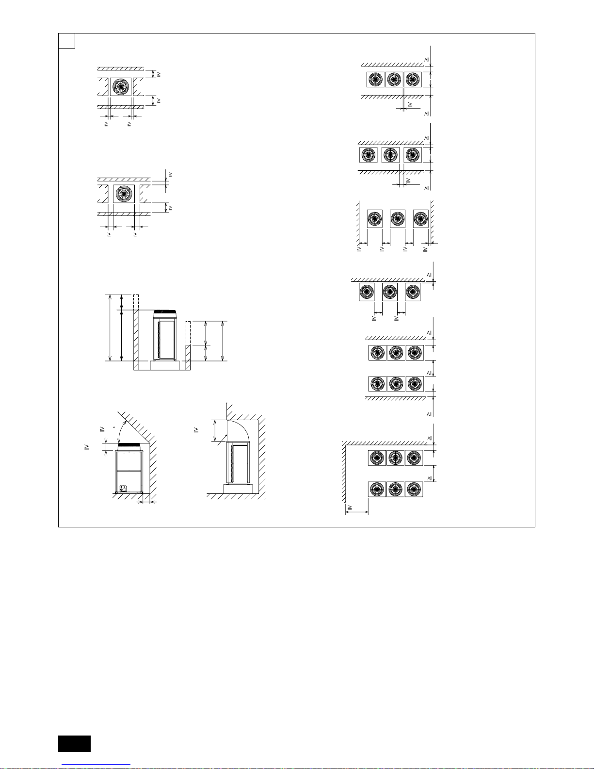
(mm)
6
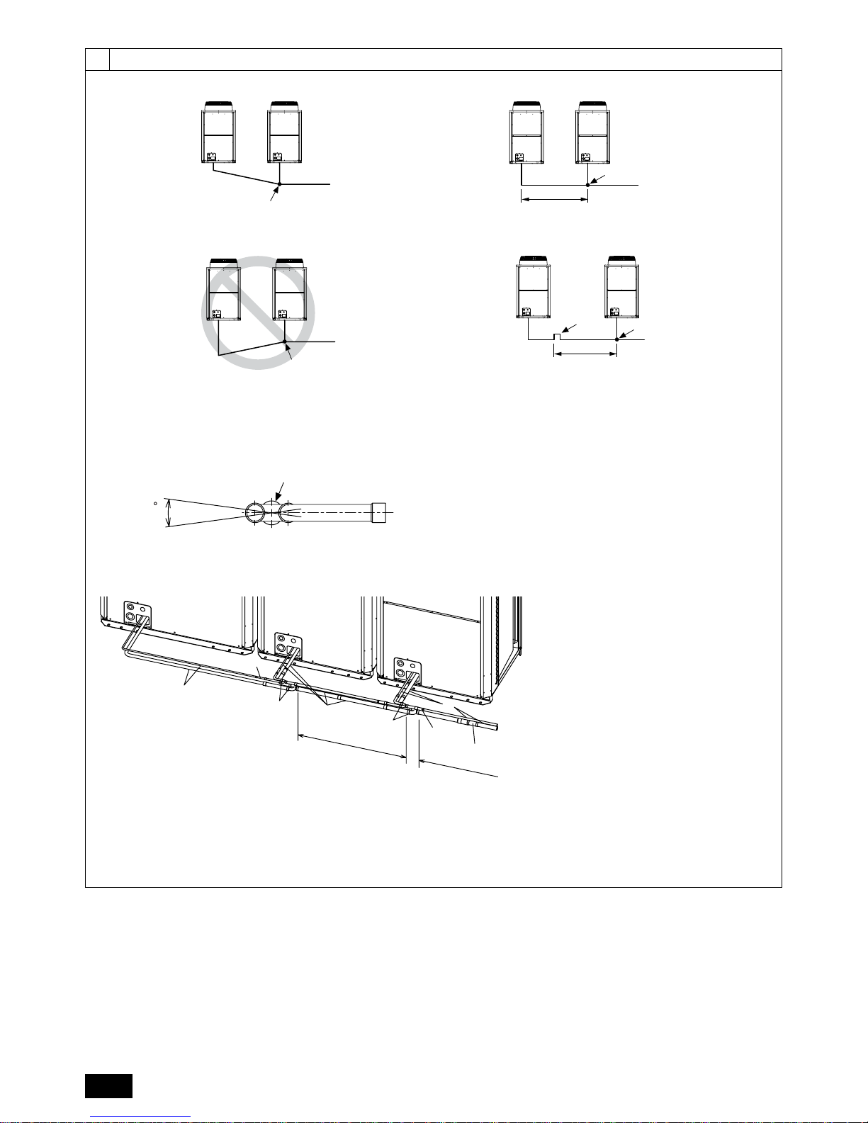
[Fig. 6.0.1]
(2)
(1)
(3)
[Fig. 6.0.2]
<A> : Top view
<B> : Side view
<C> : When there is little space up to an obstruction
A : Front
B : Unit height
C : Back
D : Air outlet guide (Procured at the site)
A : Front
B : Must be open
C : Wall height (H)
15
*
15
*
450
*
300
*
<A>
A
100
*
450
*
50
*
50
*
<A>
A
A
B
<B>
500
H
h
h
H
240
45
A
D
C
50
<C>
1000
30
450
*
300
*
C
BB
C
A
100
450
*
100
*
BB
C
C
A
450
*
100*
CC
B
A
A
A
B
450 450
15
*
C
AAA
450 450
900
300
*
300
*
BB
C
C
A
1000
*
900 300
*
B
B
C
A
(mm)
(4)
3
[Fig. 7.0.1]
1 P200 ~ P300
EP200
8m
8m
40
7
8
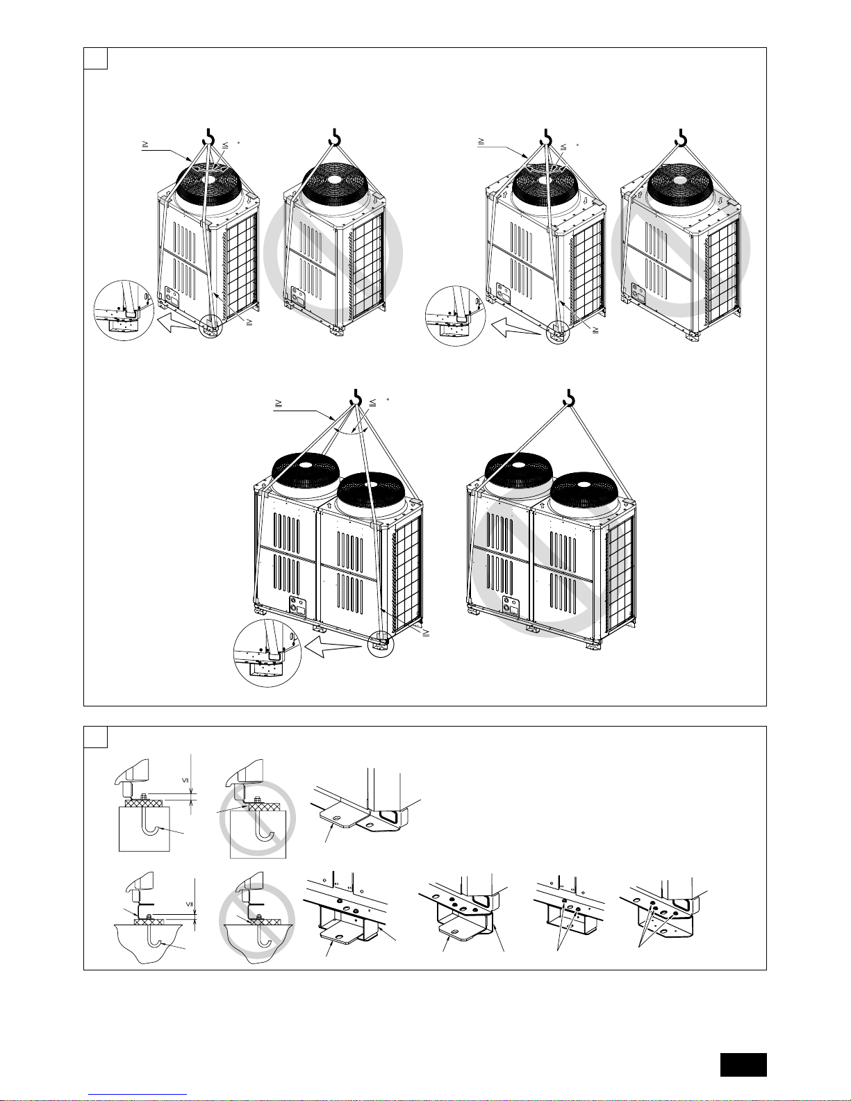
[Fig. 8.1.1]
<A> Without detachable leg
A : M10 anchor bolt procured at the site.
B : Corner is not seated.
C : Fixingbracketforhole-inanchorbolt(3locationstoxwithscrews).
D : Detachable leg
2 P350 ~ P400
EP250
3 P450
EP300
30mm
A
C
8m
8m
40
8m
40
8m
[Fig. 8.1.2]
A : Screws
30mm
A
D
B
<B> With detachable leg
CD
D
C
A
A
CD
B
4
9
9.2
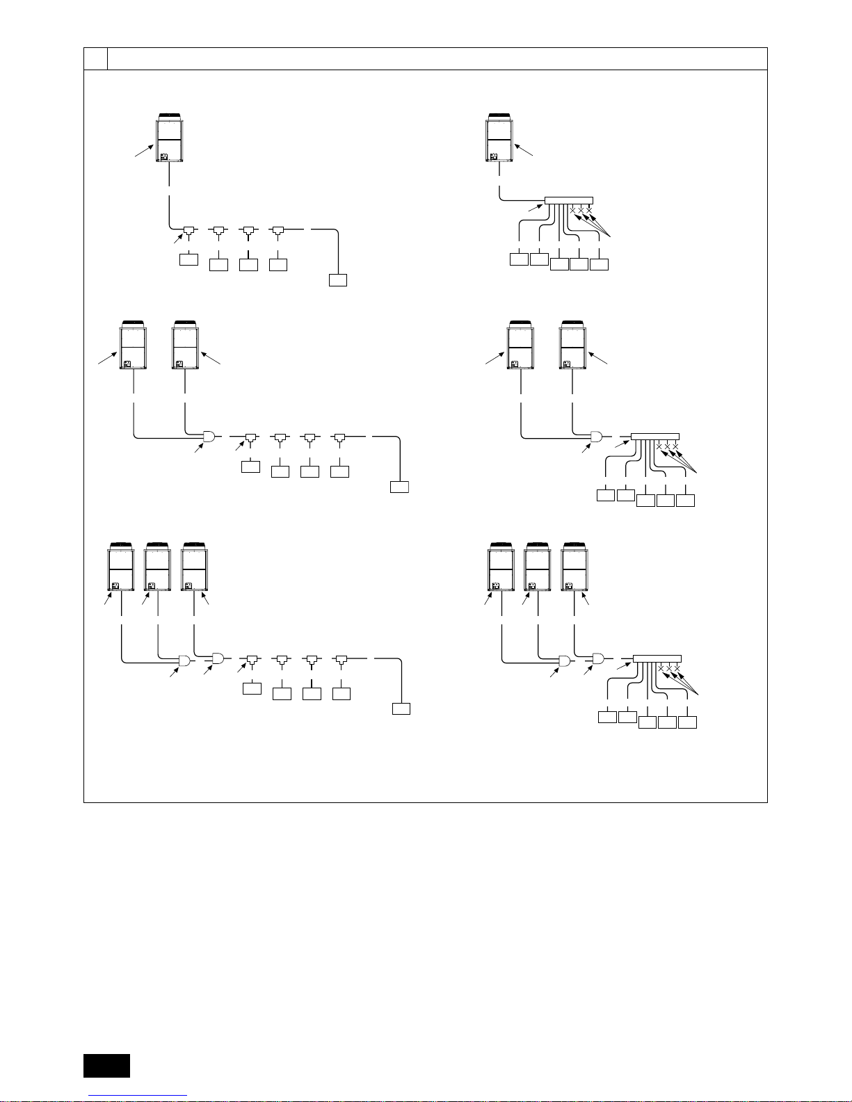
[Fig. 9.2.1]
[P200 ~ P450]
[EP200, EP250, EP300]
A : Outdoor unit
B : First branch
C : Indoor unit
D : Cap
E : Outdoor twinning kit
[P500 ~ P900]
[EP400 ~ EP600]
[P950 ~ P1250]
[EP650 ~ EP900]
B
E
A
A
2
A
1
A
B C D
e
a b c d
C
C
CCC
unit 2
A
unit 1
E
A
A
2
A
1
A
unit 2
A
unit 1
B
a
b
c d e
C
D
CC
CC
B
A
B C D
e
a b c d
C
C
CCC
A
B
A
a
b
c d e
C
D
CC
CC
A
B
B C D
e
a b c d
C
C
CCC
E
A3
A4
A2
unit 3
AAA
unit 2unit 1
E
A1
A
E
A
3
A
4
A
2
A
unit 3
AAA
unit 2unit 1
E
A
1
B
a
b
c d e
C
D
CC
CC
5
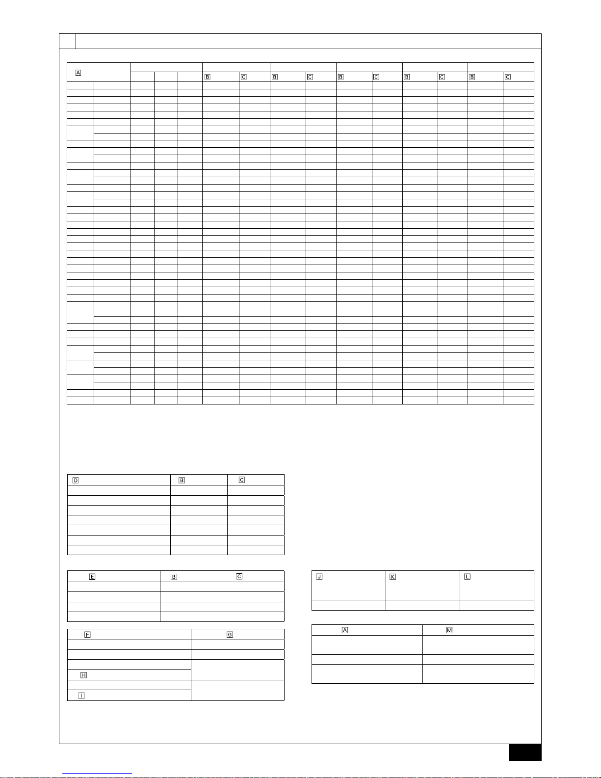
A (mm)
9.2
9
*1 ø12.7 for over 90m
*2 ø12.7 for over 40m
*3 The pipe sizes listed in columns A1 to A3 in this table correspond to the
sizes for the models listed in the unit 1, 2, and 3 columns. When the order
of the models for unit 1, 2, and 3 change, make sure to use the appropriate
pipe size.
B, C, D (mm)
a, b, c, d, e (mm)
Outdoor model
Unit combination A A1 *3 A2 *3 A3 *3 A4
unit 1 unit 2 unit 3
Liquid pipe Gas pipe Liquid pipe Gas pipe Liquid pipe Gas pipe Liquid pipe
Gas pipe
Liquid pipe Gas pipe
P200 YJM-A - - - ø9.52 ø19.05 - - - - - - - P250 YJM-A - - - *1 ø9.52 ø22.2 - - - - - - - P300 YJM-A - - - *2 ø9.52 ø22.2 - - - - - - - P350 YJM-A - - - ø12.7 ø28.58 - - - - - - - P400 YJM-A - - - ø12.7 ø28.58 - - - - - - - P450 YJM-A - - - ø15.88 ø28.58 - - - - - - - -
P500
YSJM-A P250 P250 - ø15.88 ø28.58 ø9.52 ø22.2 ø9.52 ø22.2 - - - YSJM-A1 P300 P200 - ø15.88 ø28.58 ø12.7 ø22.2 ø9.52 ø19.05 - - - -
P550 YSJM-A P300 P250 - ø15.88 ø28.58 ø12.7 ø22.2 ø9.52 ø22.2 - - - P600
YSJM-A P350 P250 - ø15.88 ø28.58 ø12.7 ø28.58 ø9.52 ø22.2 - - - YSJM-A1 P300 P300 - ø15.88 ø28.58 ø12.7 ø22.2 ø12.7 ø22.2 - - - -
P650 YSJM-A P350 P300 - ø15.88 ø28.58 ø12.7 ø28.58 ø12.7 ø22.2 - - - P700
YSJM-A P350 P350 - ø19.05 ø34.93 ø12.7 ø28.58 ø12.7 ø28.58 - - - YSJM-A1 P400 P300 - ø19.05 ø34.93 ø15.88 ø28.58 ø12.7 ø22.2 - - - -
P750 YSJM-A P400 P350 - ø19.05 ø34.93 ø15.88 ø28.58 ø12.7 ø28.58 - - - P800
YSJM-A P450 P350 - ø19.05 ø34.93 ø15.88 ø28.58 ø12.7 ø28.58 - - - -
YSJM-A1 P400 P400 - ø19.05 ø34.93 ø15.88 ø28.58 ø15.88 ø28.58 - - - P850 YSJM-A P450 P400 - ø19.05 ø41.28 ø15.88 ø28.58 ø15.88 ø28.58 - - - P900 YSJM-A P450 P450 - ø19.05 ø41.28 ø15.88 ø28.58 ø15.88 ø28.58 - - - P950 YSJM-A P400 P300 P250 ø19.05 ø41.28 ø15.88 ø28.58 ø12.7 ø22.2 ø9.52 ø22.2 ø19.05 ø34.93
P1000 YSJM-A P400 P300 P300 ø19.05 ø41.28 ø15.88 ø28.58 ø12.7 ø22.2 ø12.7 ø22.2 ø19.05 ø34.93
P1050 YSJM-A P400 P350 P300 ø19.05 ø41.28 ø15.88 ø28.58 ø12.7 ø28.58 ø12.7 ø22.2 ø19.05 ø34.93
P1100 YSJM-A P400 P350 P350 ø19.05 ø41.28 ø15.88 ø28.58 ø12.7 ø28.58 ø12.7 ø28.58 ø19.05 ø34.93
P1150 YSJM-A P450 P350 P350 ø19.05 ø41.28 ø15.88 ø28.58 ø12.7 ø28.58 ø12.7 ø28.58 ø19.05 ø34.93
P1200 YSJM-A P450 P400 P350 ø19.05 ø41.28 ø15.88 ø28.58 ø15.88 ø28.58 ø12.7 ø28.58 ø19.05 ø34.93
P1250 YSJM-A P450 P450 P350 ø19.05 ø41.28 ø15.88 ø28.58 ø15.88 ø28.58 ø12.7 ø28.58 ø19.05 ø34.93
EP200 YJM-A - - - ø9.52 ø19.05 - - - - - -
- EP250 YJM-A - - - *1 ø9.52 ø22.2 - - - - - - - EP300 YJM-A - - - *2 ø9.52 ø22.2 - - - - - - - EP400 YSJM-A EP200 EP200 - ø12.7 ø28.58 ø9.52 ø19.05 ø9.52 ø19.05 - - - EP450 YSJM-A EP250 EP200 - ø15.88 ø28.58 ø9.52 ø22.2 ø9.52 ø19.05 - - - -
EP500
YSJM-A EP300 EP200 - ø15.88 ø28.58 ø12.7 ø22.2 ø9.52 ø19.05 - - - -
YSJM-A1 EP250 EP250 - ø15.88 ø28.58 ø9.52 ø22.2 ø9.52 ø22.2 - - - EP550 YSJM-A EP300 EP250 - ø15.88 ø28.58 ø12.7 ø22.2 ø9.52 ø22.2 - - - EP600 YSJM-A EP300 EP300 - ø15.88 ø28.58 ø12.7 ø22.2 ø12.7 ø22.2 - - - EP650 YSJM-A EP250 EP200 EP200 ø15.88 ø28.58 ø9.52 ø22.2 ø9.52 ø19.05 ø9.52 ø19.05 ø19.05 ø34.93
EP700
YSJM-A EP300 EP200 EP200 ø19.05 ø34.93 ø12.7 ø22.2 ø9.52 ø19.05 ø9.52 ø19.05 ø19.05 ø34.93
YSJM-A1 EP250 EP250 EP200 ø19.05 ø34.93 ø9.52 ø22.2 ø9.52 ø22.2 ø9.52 ø19.05 ø19.05 ø34.93
EP750
YSJM-A EP300 EP250 EP200 ø19.05 ø34.93 ø12.7 ø22.2 ø9.52 ø22.2 ø9.52 ø19.05 ø19.05 ø34.93
YSJM-A1 EP250 EP250 EP250 ø19.05 ø34.93 ø9.52 ø22.2 ø9.52 ø22.2 ø9.52 ø22.2 ø19.05 ø34.93
EP800
YSJM-A EP300 EP300 EP200 ø19.05 ø34.93 ø12.7 ø22.2 ø12.7 ø22.2 ø9.52 ø19.05 ø19.05 ø34.93
YSJM-A1 EP300 EP250 EP250 ø19.05 ø34.93 ø12.7 ø22.2 ø9.52 ø22.2 ø9.52 ø22.2 ø19.05 ø34.93
EP850 YSJM-A EP300 EP300 EP250 ø19.05 ø41.28 ø12.7 ø22.2 ø12.7 ø22.2 ø9.52 ø22.2 ø19.05 ø34.93
EP900 YSJM-A EP300 EP300 EP300 ø19.05 ø41.28 ø12.7 ø22.2 ø12.7 ø22.2 ø12.7 ø22.2 ø19.05 ø34.93
Total capacity of indoor units Liquid pipe
Gas pipe
~ 140 ø9.52 ø15.88
141 ~ 200 ø9.52 ø19.05
201 ~ 300 ø9.52 ø22.2
301 ~ 400 ø12.7 ø28.58
401 ~ 650 ø15.88 ø28.58
651 ~ 800 ø19.05 ø34.93
801 ~ ø19.05 ø41.28
Model number
Liquid pipe
Gas pipe
20,25,32,40,50 ø6.35 ø12.7
63,71,80,100,125,140 ø9.52 ø15.88
200 ø9.52 ø19.05
250 ø9.52 ø22.2
4-Branching header
(Downstream unit
model total
<
200)
8-Branching header
(Downstream unit
model total
<
400)
10-Branching header
(Downstream unit
model total
<
650)
CMY-Y104-G CMY-Y108-G CMY-Y1010-G
Outdoor model
Outdoor twinning kit
P500 ~ P650
EP400 ~ EP600
CMY-Y100VBK2
P700 ~ P900 CMY-Y200VBK2
P950 ~ P1250
EP650 ~ EP900
CMY-Y300VBK2
Downstream unit model total Joint
~ 200 CMY-Y102S-G2
201 ~ 400 CMY-Y102L-G2
401 ~ 650
CMY-Y202-G2
The 1st branch of P450 ~ P650
651 ~
CMY-Y302-G2
The 1st branch of P700, P750, P800
6
9.2
9
[Fig. 9.2.2]
A
C
F
B
C
F
<A> Make sure the pipes from the twinning pipe to the outdoor unit are
sloped downwards (towards the twinning pipes).
F
C
2m
F
D
E
C
<B> When the piping on the outdoor unit side (from the twinning pipe)
exceeds 2 m, ensure a trap (gas pipe only) within 2 m.
<C> Slope of twinning pipes
15
±
F
G
<D> Pipe connection example [EP650]
A : Downward slope
B : Upward slope
C : Indoor unit
D : Trap (gas pipe only)
E : Within 2 m
F : Twinning pipe
G :
Slope of the
twinning
pipe is at an angle within ±15° to the gro
und
H : Pipes on site
I : Twinning kit
J : Straight run of pipe that is 500 mm or more
6
: ODø12.7×IDø9.52 (Included with outdoor unit)
8
: ODø19.05×IDø15.88 (Included with outdoor unit)
c
: ODø34.93×IDø28.58 (Included with outdoor unit)
(6, 8, c: Refer to item 10.2)
H
H
J
J
H
I
6
I
c
8
7
10.2
10
[Fig. 10.2.1] [Fig. 10.2.3]
AB
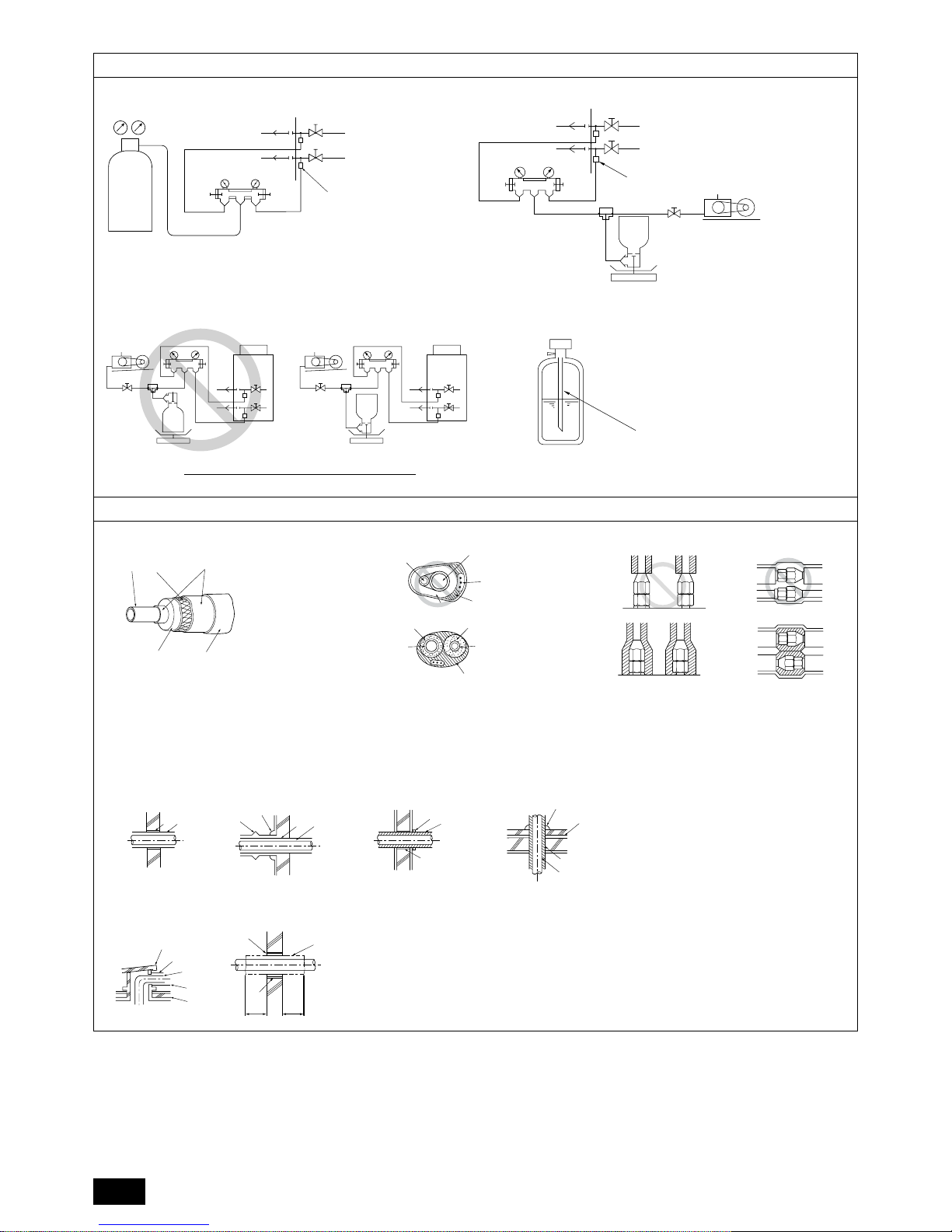
A : Exampleofclosurematerials(eldsupply)
B : Fill the gap at the site
[Fig. 10.2.2]
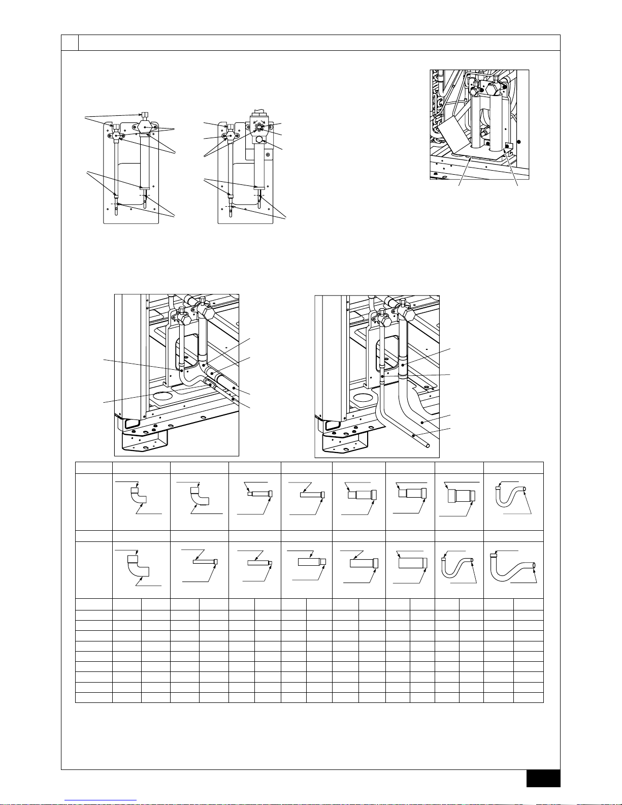
<A> Front pipe routing
<B> Bottom pipe routing
<A> Front pipe routing <B> Bottom pipe routing
<C> Included with outdoor unit
AGaspipe(eldsupplyrequired) BLiquidpipe(eldsupplyrequired)
C Shape
*4: EP650YSJM-A : Use the included connecting pipe 6 , 8, and c to connect to the twinning kit.
*5: EP700YSJM-A1 : Use the included connecting pipe 6 to connect to the twinning kit.
*6: EP750YSJM-A1 : Use the included connecting pipe 6 to connect to the twinning kit.
(*4 ~ *6 : Refer to item 9.2.)
<A> Refrigerant service valve
(liquid side/brazed type)
<B> Refrigerant service valve
(gas side/brazed type)
A : Shaft
B : Shaft
C : Stopper pin
D : Service port
E : Cap
F : Pinched connecting pipe severing portion
G : Pinched connecting pipe brazing portion
P450
EP300
<B>
<A>
F
G
E
A
D
E
D
G
F
A
O
S
C
B
D
<B>
<A>
P200~P400
EP200,EP250
90ab
<C>
A
B
123
<C>
fed
<C>
754
<C>
90ab<C>
457<C>
A
B
No.
1 3 5 7 9 a c e
C Shape
IDø19.05
ODø19.05
<Gas side>
IDø28.58
ODø28.58
<Gas side>
ODø9.52
IDø15.88
<Liquid side>
ODø12.7
IDø15.88
<Liquid side>
ODø19.05
IDø25.4
<Gas side>
ODø22.2
IDø28.58
<Gas side>
ODø34.93
IDø28.58
<Gas side>
IDø12.7
ODø12.7
<Liquid side>
No.
2 4 6 8 0 b d f
C Shape
IDø25.4
ODø25.4
<Gas side>
ODø9.52
IDø12.7
<Liquid side>
IDø9.52
ODø12.7
<Liquid side>
ODø19.05
IDø15.88
<Liquid side>
ODø22.2
IDø25.4
<Gas side>
ODø28.58
IDø25.4
<Gas side>
IDø9.52
ODø9.52
<Liquid side>
IDø15.88
ODø15.88
<Liquid side>
1 2 3 4 5 6 7 8 9 0 a b c d e f
P200 1 1
P250 1 1 1
P300 1 1 1 1
P350 1 1 1 1
P400 1 1 1 1
P450 1 1
EP200 1 1 1
EP250 1 1 1 1 1 1 1 1
EP300 1 1 1 1 1
8
[Fig. 10.3.1]
[Fig. 10.3.3]
[Fig. 10.3.2]
10.3
A
A : Nitrogen gas
B : To indoor unit
C : System analyzer
D : Low knob
E : Hi knob
F : Valve
G : Liquid pipe
H : Gas pipe
I : Outdoor unit
J : Service port
A : System analyzer
B : Low knob
C : Hi knob
D : Valve
E : Liquid pipe
F : Gas pipe
G : Service port
H : Three-way joint
I : Valve
J : Valve
K : R410A cylinder
L : Scale
M : Vacuum pump
N : To indoor unit
O : Outdoor unit
A : Syphon pipe
D
C
C
B
B
E
F
G
H
I
J
A
LOW
HI
LOW
HI
B
A
K
J
L
H
M
C
D
EN
N
O
F
G
I
10.4
[Fig. 10.4.4]
[Fig. 10.4.3][Fig. 10.4.2]
C
A
B
D
E
[Fig. 10.4.1]
B
A
D
C
E
E
E
D
A
B
A B
<A> Inner wall (concealed)
A B
D
C
<B> Outer wall
A : Steel wire B : Piping
C : Asphaltic oily mastic or asphalt
D : Heat insulation material A
E : Outer covering B
A : Liquid pipe B : Gas pipe
C : Electric wire D : Finishing tape
E : Insulator
D
F
G
B
<D> Floor (waterproong)
E
I
B
<C> Outer wall (exposed)
F
H
D
B
G
<E> Roof pipe shaft
I
A
J
1m1m
<F> Penetrating portion on re
limit and boundary wall
A : Sleeve B : Heat insulating material
C : Lagging D : Caulking material
E : Band F : Waterproong layer
G : Sleeve with edge H : Lagging material
I : Mortar or other incombustible caulking
J : Incombustible heat insulation material
B In case of the R410A cylinder having no syphon pipe.
 Loading...