

Page 1
Models PUHY-P700, P750, P800YSGM-A
Service Handbook
AIR CONDITIONERS CITY MULTI
Page 2

Contents
1 Read Before Servicing ................................................................ 6
[1] Items to Be Checked .............................................................. 6
[2] Necessary Tools and Materials .............................................. 7
[3] Piping Materials ...................................................................... 8
[4] Storage of Piping Material ...................................................... 10
[5] Piping Machining .................................................................... 11
[6] Brazing.................................................................................... 12
[7]
Airtightness Test
...................................................................... 13
[8] Vacuuming .............................................................................. 13
[9] Vacuum Drying........................................................................ 14
[10] Changing Refrigerant.............................................................. 15
[11] Remedies to be taken in case of a refrigerant leak................ 15
[12]
Characteristics of the Conventional and the New Refrigerants
.. 16
[13] Notes on Refrigerating Machine Oil........................................ 17
2 Restrictions .................................................................................. 18
[1] Electrical Work & M-NET control ............................................ 18
[2] Types of Switch Setting and Address Setting ........................ 19
[3] Examples of system connection ............................................ 21
[4] Restrictions on Refrigerant Piping Length.............................. 35
3 Components of the Outdoor Unit ................................................ 36
[1] Appearance of the Components and Refrigerant Circuit........ 36
[2] Control Box ............................................................................ 41
[3] Circuit Board .......................................................................... 44
4 Remote Controller ........................................................................ 49
[1]
Functions and Specifications of MA and ME Remote Controllers
.... 49
[2] Group Setting and Interlocking Settings that are Made on
the ME Remote Controller .................................................... 50
[3]
Interlocking Setting that is Made on the MA Remote Controller
...... 53
[4] Switching to the built-in Thermo on the remote controller ...... 54
5 Electrical Wiring Diagram ............................................................ 55
[1] Compressor unit .................................................................... 55
[2] Heat exchanger unit................................................................ 56
[3]
Power Dispatching Extension Unit for the Transmission Lines
.. 57
6 Refrigerant Circuit ........................................................................ 58
[1] Refrigerant Circuit Diagram .................................................... 58
[2] Functions of Principal Parts.................................................... 59
7 Control.......................................................................................... 62
[1] Dip Switch Functions and Their Factory Settings .................. 62
[2] Controlling the Outdoor Unit .................................................. 68
[3] Operation Flow Chart ............................................................ 75
8 Test Run ...................................................................................... 80
[1] Check Items before Test Run.................................................. 80
[2] Test Run Method .................................................................... 80
[3] Operating Characteristics and Refrigerant Amount................ 81
[4] Adjustment and Judgment of Refrigerant Amount ................ 81
[5] Refrigerant Volume Adjustment Mode Operation .................. 83
[6] Symptoms that do not Signify Problems ................................ 85
[7]
Standard Operation Data (Reference Data)
.............................. 86
9 Troubleshooting............................................................................ 88
[1] Check Code List .................................................................... 88
[2] Responding to Error Display on the Remote Controller ........ 91
[3] Investigation of Transmission Wave Shape/Noise .................. 124
[4] Troubleshooting of Principal Parts .......................................... 127
[5] Refrigerant Leak .................................................................... 143
[6] Compressor Replacement Instructions .................................. 145
[7] Collecting the Cooling Liquid from the Accumulator .............. 146
0 LED display .................................................................................. 147
[1] LED Monitor Display .............................................................. 147
Page 3
Safety Precautions
Symbols used in the text
Warning:
Failure to follow all instructions may result in serious personal injury or death.
Caution:
Failure to follow all instructions may result in personal injury or damage to the unit.
Symbols used in the illustrations
: Indicates an action that must be avoided.
: Indicates that important instructions must be followed.
: Indicates a part which must be grounded.
: Beware of electric shock (This symbol is displayed on the main unit label.) <Color : Yellow>
Warning : Carefully read the labels affixed to the main unit.
Before installing the unit, be sure to carefully read all of the following safety precautions.
These precautions provide important information regarding safety. Be sure to follow them to ensure safety.
After reading this handbook, hand it over to those who will be using the unit.
The user of the unit should keep this manual at hand and make it available to those who will be performing
repairs or relocating the unit.
Also, make it available to the new user when the user changes hands.
Be sure to carefully follow each step in this
handbook when installing the unit.
• Improper installation may result in water leak,
electric shock, smoke or fire.
Securely attach the terminal cover (panel) on the
unit.
• If installed improperly, dust and/or water may enter
the unit and present a risk of electric shock, smoke,
or fire.
Only use Refrigerant R410A as indicated on the
unit when installing or relocating the unit.
• The use of any other refrigerant or an introduction of
air into the unit circuit may cause the unit to run an
abnormal cycle and cause the unit to burst.
Do not make any changes or modifications to the
unit. In case of problems, consult the dealer.
• If repairs are not made properly, the unit may leak
water and present a risk of electric shock, or it may
produce smoke or cause fire.
Have all electrical work performed by a licensed
electrician according to the local regulations and
the instructions given in this manual. Secure a
circuit designated exclusively to the unit.
• Improper installation or a lack of circuit capacity may
cause the unit to malfunction or present a risk of
electric shock, smoke, and fire.
Have the unit professionally installed.
• Improper installation by an unqualified person may
result in water leak, electric shock, or fire.
Only use specified cables for wiring. Securely
connect each cable, and make sure that the cables
are not straining the terminals.
• Cables not connected securely and properly may
generate heat and cause fire.
Place the unit on a stable, level surface that
withstands the weight of the unit to prevent the
unit from tipping over or falling causing injury as a
result.
Take necessary safety measures against typhoons
and earthquakes to prevent the unit from falling
over.
- 1 -
Page 4
When relocating the air conditioner, consult the
dealer or a specialist.
• Improper installation may result in water leak,
electric shock, or fire.
• Consult the dealer for necessary measures to take.
After completing the service work, check for a
refrigerant gas leak.
• If leaked gas refrigerant is exposed to a heart
source such as fan heater, stove, and electric grill,
noxious gases may form.
In the event of a refrigerant gas leak, provide
adequate ventilation to the room.
• If leaked refrigerant gas is exposed to a heat source,
noxious gases may form.
With All-Fresh type air conditioners, outdoor air
may be directly blown into the room upon thermo
off. Take this into consideration when installing the
unit.
• Direct exposure to outdoor air may present a health
hazard, and it may also cause food items to
deteriorate.
When installing the unit in a small room, safeguard
against hypoxia that results from leaked refrigerant
reaching the threshold level.
Do not touch the fins on the heat exchanger with
bare hands: they are sharp and dangerous.
Precautions for Handling Units for Use with R410A
Caution
Warning : Carefully read the labels affixed to the main unit.
Do not try to defeat the safety features of the
devices, and do not change the settings.
• Defeating the safety features on the unit such as the
pressure switch and temperature switch or using
parts other than those specified by Mitsubishi
Electric may result in fire or explosion.
Use refrigerant pipes made of C1220 phosphorus
deoxidized copper categorized under H3000
(Copper and Copper Alloy Seamless Pipes and
Tubes), a standard set by JIS. Keep the inner and
outer surfaces of the pipes clean and free of
contaminants such as sulfur, oxides, dust/dirt,
shaving particles, oils, and moisture.
• Contaminants inside the refrigerant piping will cause
the refrigerant oil to deteriorate.
Do not use the following tools that have been used
with the conventional refrigerants.Prepare tools
that are for exclusive use with R410A.
(Gauge manifold, charging hose, gas leak detector,
reverse-flow check valve, refrigerant charge base,
vacuum gauge, and refrigerant recovery
equipment.)
• If refrigerant and /or refrigerant oil left on these tools
are mixed in with R410A, or if water is mixed with
R410A, it will cause the refrigerant to deteriorate.
• Since R410A does not contain chlorine, gas-leak
detectors for conventional refrigerators will not work.
Only use specified parts.
• Have the unit professionally installed.
Improper installation may cause water leak, electric
shock, smoke, or fire.
Use a vacuum pump with a reverse-flow-check
valve.
• If other types of valves are used, the vacuum pump
oil will flow back into the refrigerant cycle and cause
the refrigerator oil to deteriorate.
Do not use the existing refrigerant piping
• The old refrigerant and refrigerator oil in the existing
piping contain a large amount of chlorine, which will
cause the refrigerator oil in the new unit to
deteriorate.
• R410A is a high-pressure refrigerant, and the use of
the existing piping may result in bursting.
- 2 -
Page 5
Before Installing the Unit
Warning
Caution
Store the piping to be used during installation
indoors, and keep both ends of the piping sealed
until immediately before brazing. (Keep elbows and
other joints wrapped in plastic.)
• If dust, dirt, or water enters the refrigerant cycle, it
may cause the oil in the unit to deteriorate or may
cause the compressor to malfunction.
Use a small amount of ester oil, ether oil, or
alkylbenzene to coat flares and flange connections.
• A large amount of mineral oil will cause the
refrigerating machine oil to deteriorate.
Do not use a charging cylinder.
• The use of charging cylinder will change the
composition of the refrigerant and lead to power
loss.
Exercise special care when handling the tools.
• An introduction of foreign objects such as dust, dirt,
or water into the refrigerant cycle will cause the
refrigerating machine oil to deteriorate.
Only use R410A refrigerant.
• The use of refrigerants containing chlorine (i.e. R22)
will cause the refrigerant to deteriorate.
Use liquid refrigerant to charge the system.
• Charging the unit with gas refrigerant will cause the
refrigerant in the cylinder to change its composition
and will lead to a drop in performance.
Do not install the unit in a place where there is a
possibility of flammable gas leak.
• Leaked gas accumulated around the unit may start a
fire.
Do not use the unit to preserve food, animals,
plants, artifacts, or for other special purposes.
• The unit is not designed to provide adequate
conditions to preserve the quality of these items.
When installing the unit in a hospital, take
necessary measures against noise.
• High-frequency medical equipment may interfere
with the normal operation of the air conditioning unit
or the air conditioning unit may interfere with the
normal operation of the medical equipment.
Do not use the unit in an unusual environment.
• The use of the unit in the presence of a large
amount of oil, steam, acid, alkaline solvents, or
special types of sprays may lead to a remarkable
drop in performance and/or malfunction and
presents a risk of electric shock, smoke, or fire.
• The presence of organic solvents, corroded gas
(such as ammonia, sulfur compounds, and acid)
may cause gas or water leak.
Do not place the unit on or over things that may
not get wet.
• When humidity level exceeds 80% or when the
drainage system is clogged, indoor units may drip
water.
• Installation of a centralized drainage system for the
outdoor unit may also need to be considered to
prevent water drips from the outdoor units.
- 3 -
Page 6
Before Installing (Relocating) the Unit or Performing Electric Work
Caution
Do not spray water on the air conditioners or
immerse the air conditioners in water.
• Water on the unit presents a risk of electric shock.
Install a breaker for current leakage at the power
source to avoid the risk of electric shock.
• Without a breaker for current leakage, there is a risk
of electric shock, smoke, or fire.
Use wires that are specified in the installation
manual.
• The use of other types of wires presents a risk of
electrical current leak, electric shock, smoke, or fire.
Periodically check the platform on which the unit is
placed for damage to prevent the unit from falling.
• If the unit is left on a damaged platform, it may
topple over, causing injury.
Ground the unit.
• Do not connect the grounding on the unit to gas
pipes, water pipes, lightning rods, or the grounding
terminals of telephones. Improper grounding
presents a risk of electric shock, smoke, fire, or the
noise caused by improper grounding may cause the
unit to malfunction.
Use breakers and fuses (electrical current breaker,
remote switch <switch + Type-B fuse>, molded
case circuit breaker) with a proper current
capacity.
• The use of large-capacity fuses, steel wire, or
copper wire may damage the unit or cause smoke or
fire.
When installing draining pipes, follow the
instructions in the manual, and make sure that they
properly drain water so as to avoid dew
condensation.
• If not installed properly, they may cause water leaks
and damage the furnishings.
Make sure the wires are not subject to tension.
• If the wires are too taut, they may break or generate
heat and/or smoke and cause fire.
Exercise caution when transporting products.
• Do not try to move equipments over 20kg (approx.
44 lbs.) alone.
• Do not use the PP bands used on some packages
for transportation.
• Wear protective gloves to avoid injury caused by
touching the fins on the heat exchanger with bare
hands.
• When using a suspension bolt to transport the heatsource unit, use a four-point suspension. A threepoint suspension does not provide adequate stability
and presents a risk of accidents.
Properly dispose of the packing materials.
• Things such as nails and wood pieces may be
included in the package. Dispose of them properly to
prevent injury.
• Plastic bags present a choking hazard to children.
Tear up the plastic bags before disposing of them to
prevent accidents.
- 4 -
Page 7
Before the Test Run
Caution
Turn on the unit at least 12 hours before the test
run.
• Keep the unit on throughout the season.
Turning the unit off during the season may cause
problems.
Do not turn off the power immediately after
stopping the unit.
• Allow for at least five minutes before turning off the
unit; otherwise, the unit may leak water or
experience other problems.
Do not operate the unit without panels and safety
guards in their proper places.
• They are there to keep the users from injury from
accidentally touching rotating, high-temperature, or
high-voltage parts.
Do not touch the refrigerant pipes with bare hands
during and immediately after operation.
• Depending on the state of the refrigerant in the
system, certain parts of the unit such as the pipes
and compressor may become very cold or hot and
may subject the person to frost bites or burning.
Do not operate switches with wet hands to avoid
electric shock.
Do not operate the unit without air filters.
• Dust particles in the air may clog the system and
cause malfunction.
- 5 -
Page 8

- 6 -
¡¡
Read Before Servicing
[1] Items to Be Checked
1. Verify the type of refrigerant used by the unit to be serviced.
Refrigerant Type : R410A
2. Check the symptom exhibited by the unit to be serviced.
Look in this service handbook for symptoms relating to the refrigerant cycle.
3. Be sure to carefully read the Safety Precautions at the beginning of this document.
4. Prepare necessary tools: Prepare tools exclusive for use with each refrigerant type.
Refer to P7 for more information.
5. If the refrigerant circuit is opened (to repair a gas leak etc.), the dryer needs to be replaced.
Only use the dryer designed specifically for Citi Multi YGM-A. The use of other dryers may result in malfunctions.
✻ Replace the dryer after completing all the repairs on the refrigerant circuit.
(If left exposed to air, the dryer will absorb moisture. Replace the dryer as quickly as possible after removing
the old one.)
✻ When all of the following conditions are met, the replacement of drier is not necessary.
(1) Do not leave the refrigerant circuit longer than 2 hours.
(2) Cover the opening end with a cap or tape to keep moisture from entering.
(3) Also cover the opening end of the new part with a cap or tape
(4) Do not perform the task in the rain.
(5) Evacuate the refrigerant circuit as specified.
6. Verification of the connecting pipes: Verify the type of refrigerant used for the unit to be
moved or replaced.
• Use pipes made of phosphorus deoxidized copper. Keep the inner and outer surfaces of the pipes clean and
free of contaminants such as sulfur, oxides, dust/dirt, shaving particles, oils, and moisture.
• Contaminants inside the refrigerant piping will cause the refrigerant oil to deteriorate.
7. If there is a gas leak or if the remaining refrigerant is exposed to an open flame, a noxious gas
hydrofluoric acid may form. Keep workplace well ventilated.
CAUTION
1. Install new pipes immediately after removing old ones to keep moisture out of the refrigerant circuit.
2. Chloride in some types of refrigerants such as R22 will cause the refrigerating machine oil to
deteriorate.
Page 9
- 7 -
[2] Necessary Tools and Materials
Prepare the following tools and materials necessary for installing and servicing the unit.
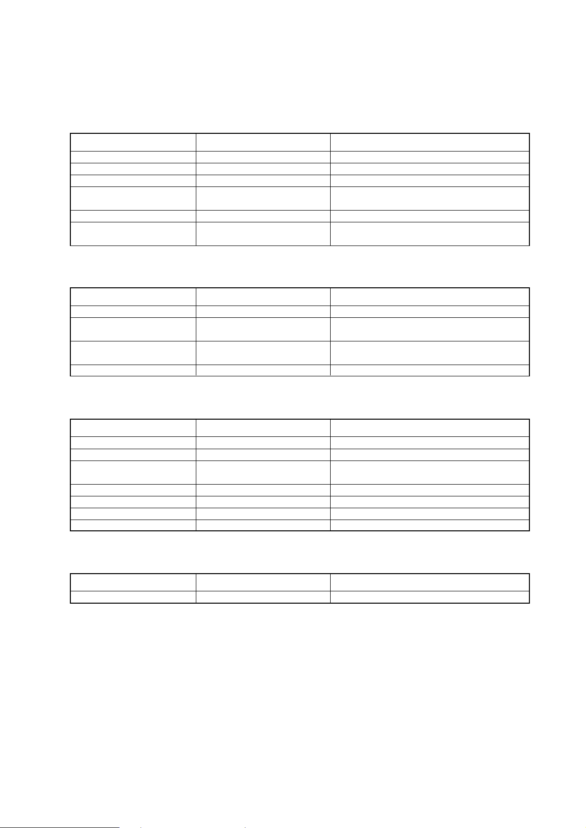
[Necessary tools for use with R410A (Adaptability of tools that are for use with R22 and R407C)]
1. To be used exclusively with R410A (not to be used if used with R22 or R407C)
Tools/Materials NotesUse
Gauge Manifold
Charging Hose
Refrigerant Recovery Equipment
Refrigerant Cylinder
Refrigerant Cylinder Charging Port
Flare Nut
Evacuating, refrigerant charging
Evacuating, refrigerant charging
Refrigerant recovery
Refrigerant charging
Refrigerant charging
Connecting the unit to piping
5.09MPa on the High-pressure side.
Hose diameter larger than the conventional ones.
Write down the refrigerant type.
Pink in color at the top of the cylinder.
Hose diameter larger than the conventional ones.
Use Type-2 Flare nuts.
(That are in compliance with JIS B 8607).
2. Tools and materials that may be used with R410A with some restrictions
Tools/Materials NotesUse
Gas leak detector
Vacuum Pump
Flare Tool
Refrigerant Recovery Equipment
Detection of gas leaks
Vacuum drying
Flare machining of piping
Recovery of refrigerant
The ones for HFC type refrigerant may be used.
May be used if a reverse flow check adaptor is
attached.
Changes have been made in the flare machining
dimension. Refer to the next page.
May be used if designed for use with R410A.
3. Tools and materials that are used with R22 or R407C that can also be used with R410A
Tools/Materials NotesUse
Vacuum Pump with a Check valve
Bender
Torque Wrench
Pipe Cutter
Welder and Nitrogen Cylinder
Refrigerant Charging Meter
Vacuum Gauze
Vacuum drying
Bending pipes
Tightening flare nuts
Cutting pipes
Welding pipes
Refrigerant charging
Checking vacuum degree
Only ø 12.70 (1/2”) and ø 15.88 (5/8”) have a
larger flare machining dimension.
4. Tools and materials that must not be used with R410A
Tools/Materials NotesUse
Charging Cylinder Refrigerant Charging Must not be used with R410A-type units.
Tools for R410A must be handled with special care; keep moisture and dust from entering the
cycle.
Page 10
Type-O pipes Soft copper pipes (annealed copper pipes)
They can be bent easily with hands.
Type-1/2H pipes Hard copper pipes (straight pipes)
Stronger than type-O pipes of the same radial thickness.
- 8 -
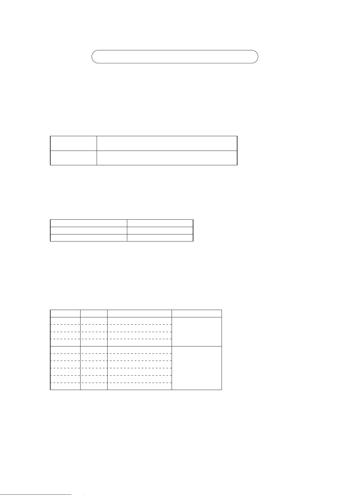
[3] Piping Materials
NOOK
New Piping Existing Piping
Do not use the existing piping!
<Types of copper pipe>
• The distinction between type-O and type-1/2H pipes is made based on the strength of the pipes themselves.
• Type-O pipes are soft and can easily be bent with hands.
• Type-1/2H pipes are considerably stronger than type-O pipes of the same radial thickness.
Use pipes made of phosphorus deoxidized copper.
Since the operation pressure of the units that use R410A is higher than that of the units for use with R22, use
pipes with at least the radial thickness specified in the chart below.
(Pipes with a radial thickness of 0.7 mm or less may not be used.)
Maximum Operation Pressure Applicable Refrigerants
3.45 MPa
4.30 MPa
R22, R407C etc.
R410A
<Types of Copper Pipes (Reference)>
✻ Use pipes that meet the local standards.
Type-O pipes
Type-1/2H or
H pipes
Size(mm) Size(inch) Radial Thickness(mm) Type
ø 6.35
ø 9.52
ø 12.7
ø 15.88
ø 19.05
ø 22.2
ø 25.4
ø 28.58
ø 31.75
ø 34.93
1/4”
3/8”
1/2”
5/8”
3/4”
7/8”
1”
1 1/8”
1 1/4”
1 3/8”
0.8t
0.8t
0.8t
1.0t
1.0t
1.0t
1.0t
1.0t
1.1t
1.2t
<Piping Materials/Radial Thickness>
✻ Although it was possible to use type-O for pipes with a size of up to ø19.05 (3/4”) with conventional refriger-
ants, use type-1/2H pipes for units that use R410A. (Type-O pipes may be used if the pipe size is
ø19.05 and
the radial thickness is 1.2t.)
✻ The table shows the standards in Japan. Using this table as a reference, choose pipes that meet the local
standards.
Page 11
- 9 -
“Radial thickness” and “Refrigerant Types” are indicated on the insulation material on the piping materials for the
new refrigerant.
Indication of the radial thickness (mm) Indication of the refrigerant type
Radial thickness Symbols
0.8
1.0
08
10
Refrigerant type Symbol
Type1 R22, R407C
Type2 R410A
1
2
<Example of the symbols indicated on the insulation material>
The type of piping materials can also be found on the package.
<Example of a label found on the package>
~08-2~
Appears every 1 m
2 : common to type 1 and type 2
Refrigerant Type : R22,R407C,R410A
Bore diameter and radial thickness of the copper piping : 9.52✕0.8, 15.88✕1.0
<Indication of the radial thickness and refrigerant type on the piping materials>
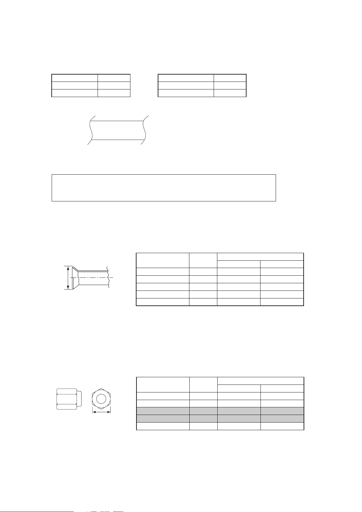
The flare machining dimensions for units that use R410A is larger than those for units that use R22 in order to
increase air tightness.
If a clutch type flare tool is used to machine flares on units that use R410A, make the protruding part of the
pipe between 1.0 and 1.5mm. Copper pipe gauge for adjusting the length of pipe protrusion is useful.
Flare Machining Dimension(mm)
External dimension
of pipes
Size
Dimension A
R410A
ø 6.35
ø 9.52
ø 12.7
ø 15.88
ø 19.05
1/4”
3/8”
1/2”
5/8”
3/4”
9.1
13.2
16.6
19.7
24.0
R22
9.0
13.0
16.2
19.4
23.3
Dimension A
<Flare Machining (type-O and OL only)>
Type-2 flare nuts instead of type-1 s are used to increase the strength. The size of some of the flare nuts have
also been changed.
Flare nut dimension(mm)
External dimension
of pipes
Size
Dimension B
R410A(Type2)
ø 6.35
ø 9.52
ø 12.7
ø 15.88
ø 19.05
1/4”
3/8”
1/2”
5/8”
3/4”
17.0
22.0
26.0
29.0
36.0
R22(Type1)
17.0
22.0
24.0
27.0
36.0
Dimension B
<Flare Nut>
✻ The table shows the standards in Japan. Using this table as a reference, choose pipes that meet the local
standards.
Page 12
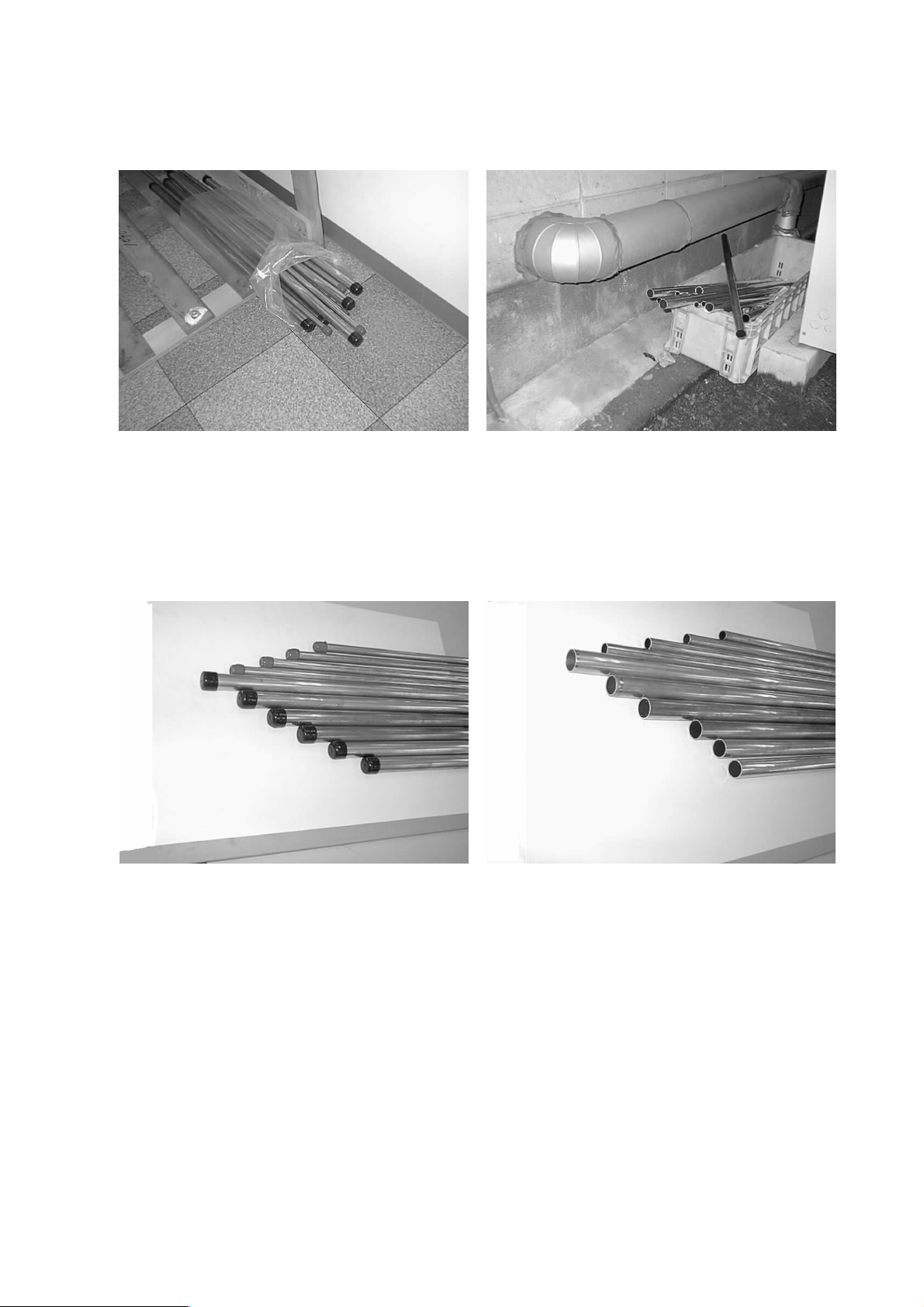
Store the pipes to be used indoors. (Warehouse at site or owner’s warehouse)
Storing them outdoors may cause dirt, waste, or water to infiltrate.
Both ends of the pipes should be sealed until immediately before brazing.
Wrap elbows and T’s in plastic bags for storage.
✻
The new refrigerator oil is 10 times more hygroscopic than the conventional refrigerator oil (such as Suniso). Water
infiltration in the refrigerant circuit may deteriorate the oil or cause a compressor failure. Piping materials must be
stored with more care than with the conventional refrigerant pipes.
OK
OK
NO
NO
- 10 -
[4] Storage of Piping Material
1. Storage location
2. Pipe sealing before storage
Page 13

Use ester oil, ether oil or alkylbenzene (small amount) as the refrigerator oil to coat flares and flange connections.
Reason :
1. The refrigerator oil used for the equipment is highly hygroscopic and may introduce water inside.
Notes :
• Introducing a great quantity of mineral oil into the refrigerant circuit may also cause a compressor failure.
• Do not use oils other than ester oil, ether oil or alkylbenzene.
- 11 -
[5] Piping Machining
Page 14
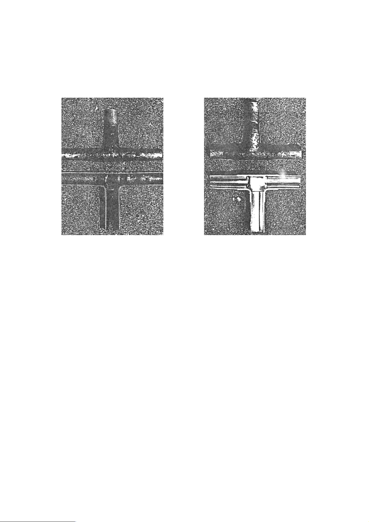
No changes from the conventional method, but special care is required so that foreign matter (ie. oxide scale, water, dirt,
etc.) does not enter the refrigerant circuit.
Example : Inner state of brazed section
When non-oxide brazing was not used When non-oxide brazing was used
Items to be strictly observed :
1. Do not conduct refrigerant piping work outdoors on a rainy day.
2. Apply non-oxide brazing.
3. Use a brazing material (BCuP-3) which requires no flux when brazing between copper pipes or between a copper pipe
and copper coupling.
4. If installed refrigerant pipes are not immediately connected to the equipment, then braze and seal both ends of them.
Reasons :
1. The new refrigerant oil is 10 times more hygroscopic than the conventional oil. The probability of a machine failure if
water infiltrates is higher than with conventional refrigerant oil.
2. A flux generally contains chlorine. A residual flux in the refrigerant circuit may generate sludge.
Note :
• Commercially available antioxidants may have adverse effects on the equipment due to its residue, etc. When
applying non-oxide brazing, use nitrogen.
- 12 -
[6] Brazing
Page 15
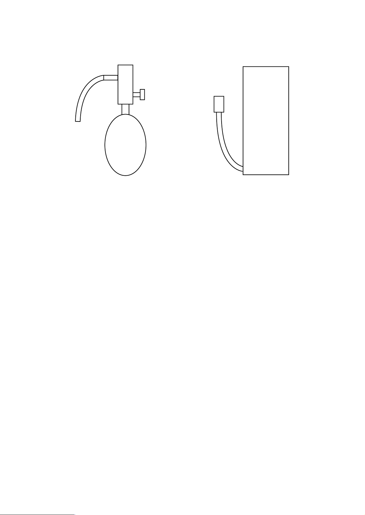
No changes from the conventional method. Note that a refrigerant leakage detector for R22 or R407C cannot detect
R410A leakage.
Halide torch R22 or R407C leakage detector
Items to be strictly observed :
1. Pressurize the equipment with nitrogen up to the design pressure and then judge the equipment’s airtightness, taking
temperature variations into account.
2. When investigating leakage locations using a refrigerant, be sure to use R410A.
3. Ensure that R410A is in a liquid state when charging.
Reasons :
1. Use of oxygen as the pressurized gas may cause an explosion.
2. Charging with R410A gas will lead the composition of the remaining refrigerant in the cylinder to change and this
refrigerant can then not be used.
Note :
• A leakage detector for R410A is sold commercially and it should be purchased.
1. Vacuum pump with check valve
A vacuum pump with a check valve is required to prevent the vacuum pump oil from flowing back into the refrigerant
circuit when the vacuum pump power is turned off (power failure).
It is also possible to attach a check valve to the actual vacuum pump afterwards.
2. Standard degree of vacuum for the vacuum pump
Use a pump which reaches 65Pa or below after 5 minutes of operation.
In addition, be sure to use a vacuum pump that has been properly maintained and oiled using the specified oil. If the
vacuum pump is not properly maintained, the degree of vacuum may be too low.
3. Required accuracy of the vacuum gauge
Use a vacuum gauge that can measure up to 650Pa. Do not use a general gauge manifold since it cannot measure a
vacuum of 650Pa.
4. Evacuating time
• Evacuate the equipment for 1 hour after 650Pa has been reached.
• After envacuating, leave the equipment for 1 hour and make sure the that vacuum is not lost.
5. Operating procedure when the vacuum pump is stopped
In order to prevent a backflow of the vacuum pump oil, open the relief valve on the vacuum pump side or loosen the
charge hose to drawn in air before stopping operation.
The same operating procedure should be used when using a vacuum pump with a check valve.
NO
NO
- 13 -
[7] Airtightness Test
[8] Vacuuming
Page 16
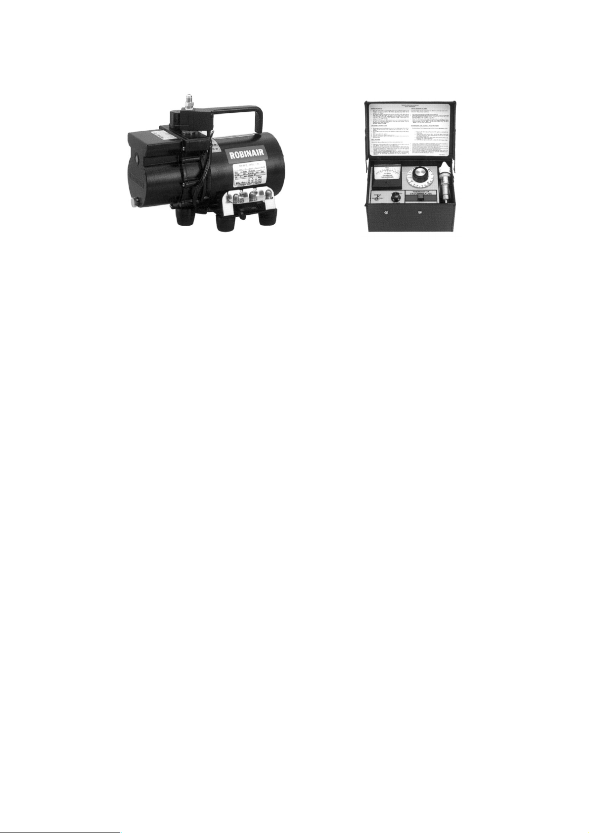
Recommended vacuum gauge : ROBINAIR 14010 Thermistor Vacuum Gauge
1. Vacuum pump with reverse-flow check valve (Photo 1)
To prevent vacuum pump oil from flowing back into the refrigerant circuit upon turning off the vacuum pump’s power
source, use a vacuum pump equipped with a reverse flow check valve.
A check valve may also be added to the vacuum pump currently in use.
2. Standard of vacuum degree (Photos 1 and 2)
Use a vacuum pump that shows a vacuum degree of 65Pa or less after 5 minutes of operation. Use a pump well-
maintained with an appropriate lubricant.
3. Required precision of vacuum gauge
Use a vacuum gauge that registers a vacuum degree of 650Pa and measures at intervals of 130Pa. (A recommended
vacuum gauge is shown in Photo 2.)
Do not use a vacuum gauge that does not register a vacuum degree of 650Pa.
4. Evacuation time
• After the vacuum gauge has registered the vacuum degree of 650Pa, evacuate for 1 hour. (A thorough vacuum drying
removes moisture in the pipes.)
• Verify that the vacuum degree has not risen by more than 130Pa 1 hour after evacuation. A rise by less than 130Pa is
acceptable.
• If it has exceeded by more than 130Pa, conduct vacuuming following the instructions in the “6. Special vacuum drying”
section.
5. Procedures for stopping vacuum pump
To prevent the reverse flow of vacuum pump oil, open the relief valve on the vacuum pump side, or draw in air by
loosening the charge hose, and then stop the operation.
The same procedures should be followed when stopping a vacuum pump with a reverse-flow check valve.
6. Special vacuum drying
• When 650Pa or lower degree of vacuum cannot be attained after 3 hours of evacuation, it is likely that water has
penetrated the system or that there is a leak. When water infiltration is suspected, vacuum with nitrogen gas.
After breaking the vacuum, pressurize the system with nitrogen gas to a degree of 0.05MPa, and conduct an evacuation
again. Repeat it until 650Pa or lower degree of vacuum is attained or the vacuum pressure rise will be lost.
• Only use nitrogen gas for vacuum breaking. (Use of oxygen may cause an explosion.)
Photo 1 15010H Photo 2 14010
- 14 -
[9] Vacuum Drying
Page 17
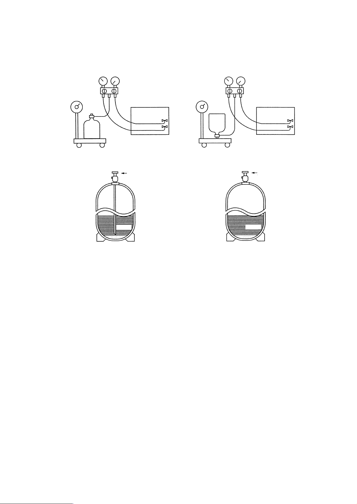
R410A must be in a liquid state when charging.
For a cylinder with a syphon attached For a cylinder without a syphon attached
Cylinder color identification R407C-Gray Charged with liquid refrigerant
R410A-Pink
Reasons :
1.
Note :
• In the case of a cylinder with a syphon, liquid R410A is charged without turning the cylinder up side down. Check the
type of cylinder before charging.
Cylin-
der
Cylin-
der
Valve
Val ve
Liquid
Liquid
R410A is a pseudo-azeotropic refrigerant (boiling point R32 = -52˚C, R125 = -49˚C) and can roughly be handled
in the same way as R22; however, be sure to fill the refrigerant from the liquid side, for doing so from the gas
side will somewhat change the composition of the refrigerant in the cylinder.
When refrigerant leaks, additional refrigerant may be charged. (Add the refrigerant from the liquid side.)
✻Refer to 9-[5].
- 15 -
[10] Changing Refrigerant
[11] Remedies to be taken in case of a refrigerant leak
Page 18
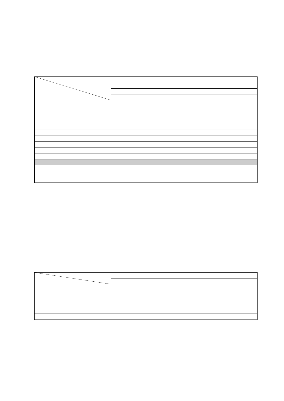
Composition (wt%)
Type of refrigerant
Chloride
Safety Class
Molecular Weight
Boiling Point
Steam Pressure (25
˚C,MPa)(gauge)
Saturated Steam Density (25
˚C,kg/m3)
Flammability
Ozone Depletion Coefficient (ODP)✻1
Global Warming Coefficient (GWP)✻2
Refrigerant charging method
Addition of refrigerant in case of a leak
R410A
R32/R125
(50/50)
Simulated azeotropic
refrigerant
Not contained
A1/A1
72.6
-51.4
1.557
64.0
Non-flammable
0
1730
Liquid charging
Possible
R407C
R32/R125/R134a
(23/25/52)
Non-azeotropic
refrigerant
Not contained
A1/A1
86.2
-43.6
0.9177
42.5
Non-flammable
0
1530
Liquid charging
Possible
New Refrigerant
(HFC system)
Conventional Refrigerant
(HCFC system)
R22
R22
(100)
Single refrigerant
Contained
A1
86.5
-40.8
0.94
44.4
Non-flammable
0.055
1700
Gas charging
Possible
✻1: When CFC11 is used as a reference ✻2: When CO
2 is used as a reference
- 16 -
[12] Characteristics of the Conventional and the New Refrigerants
1. Chemical property
As with R22, the new refrigerant (R410A) is low in toxicity and a chemically stable non-flammable refrigerant.
However, because the specific gravity of steam is greater than that of air, leaked refrigerant in a closed room will
accumulate at the bottom of the room and may cause hypoxia. Also, leaked refrigerant exposed directly to an
open flame will generate noxious gasses. Use the unit in a well-ventilated room.
R410A
MPa
0.30
0.70
1.34
2.31
3.73
4.17
-20
0
20
40
60
65
R407C
MPa
0.18
0.47
0.94
1.44
2.44
2.75
R22
MPa
0.14
0.40
0.81
1.44
2.33
2.60
Pressure (gauge)
Temperature (
˚C)
3. Pressure Characteristics
The pressure in the units that use R410A is 1.6 times as great as that in the units that use R22.
2. Refrigerant Composition
Because R410A is a simulated azeotropic refrigerant, it can be handled in almost the same manner as a single
refrigerant such as R22. However, if the refrigerant is removed in the vapor phase, the composition of the refriger
ant in the cylinder will somewhat change.
Remove the refrigerant in the liquid phase. Additional refrigerant may be added in case of a refrigerant leak.
Page 19
- 17 -
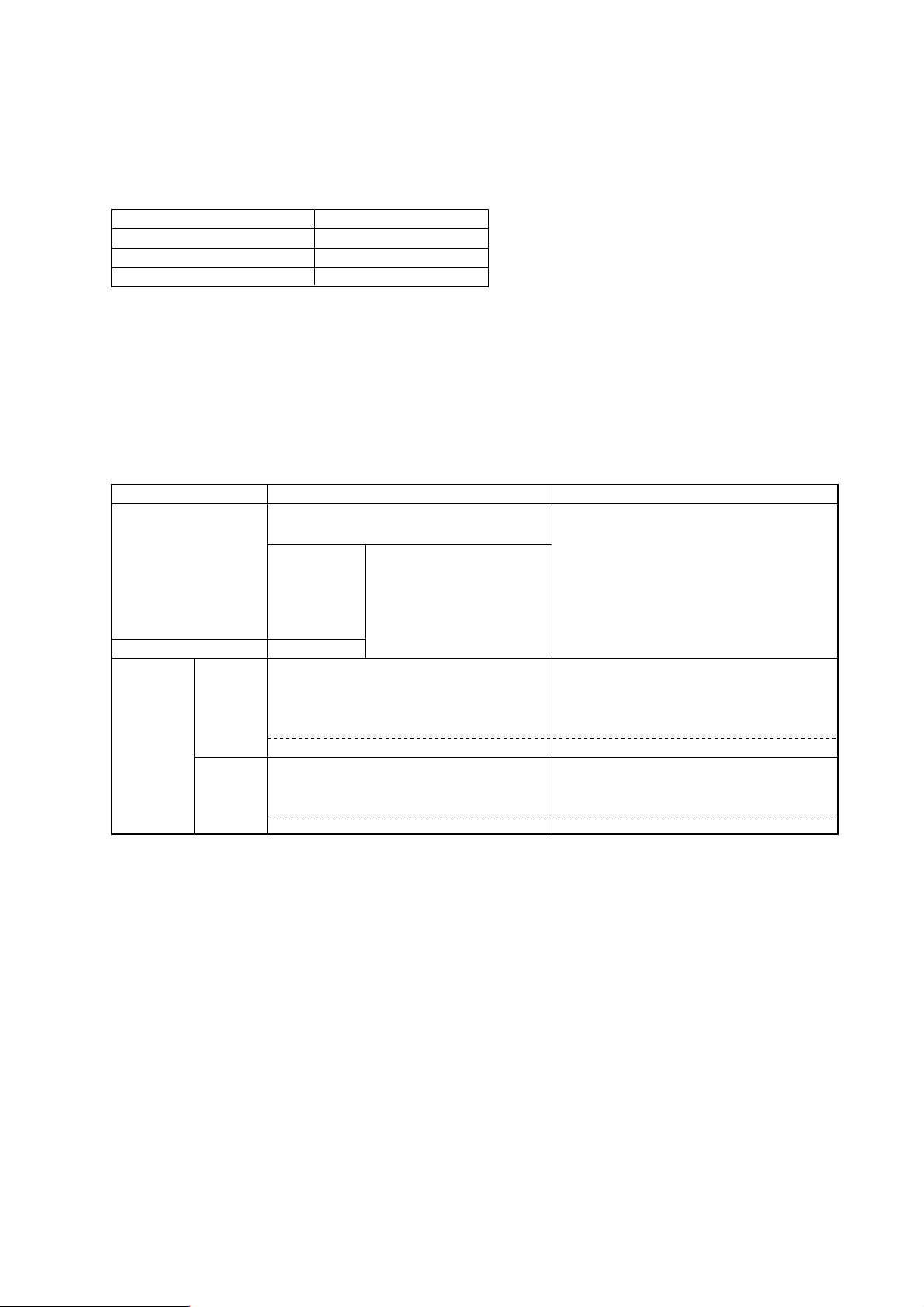
Refrigerant Refrigerating machine oil
R22
R407C
R410A
Mineral oil
Ester oil
Ester oil
[13] Notes on Refrigerating Machine Oil
1. Refrigerating Machine Oil in the HFC Refrigerant System
HFC type refrigerants use a refrigerating machine oil different from that used in the R22 refrigerant system.
Please note that the ester oil sealed in the unit is not the same as commercially available ester oil.
Cause Symptom
Clogged expansion valve and capillary
Poor cooling performance
Compressor overheat
Poor motor insulation
Motor burning
Coppering of the orbiting part
Locking
Burning in the orbiting part
Expansion valve/capillary
Poor cooling performance
Drier clogging
Compressor overheat
Burning in the orbiting part
Expansion valve and capillary clogging
Poor cooling performance
Compressor overheat
Burning in the orbiting part
Effects on the refrigeration cycle
Sludge formation
Generation of acid
Oxidization
Oil degradation
Water infiltration
Air infiltration
Infiltration
of
contaminants
Dust, dirt
Mineral oil
etc.
Expansion valve and capillary freeze
Hydrolysis
Oxidization
Adhesion to expansion valve and capillary
Infiltration of contaminants into the compressor
Sludge formation and adhesion
Oil degradation
2. Effects of the ✻Contaminants in the System
Refrigerating machine oil used in the HFC system must be handled more carefully than conventional mineral oils.
The table below shows the effects of air, moisture, and contaminants in the refrigerating machine oil on the refrigeration cycle.
✻ “ Contaminants ” is defined as moisture, air, process oil, dust/dirt, the wrong types of refrigerant and refrigerat-
ing machine oil.
<The Effects of Air, Moisture, and Contaminants in the Refrigerating Machine Oil on the Refrigeration Cycle.>
Page 20
OK NO
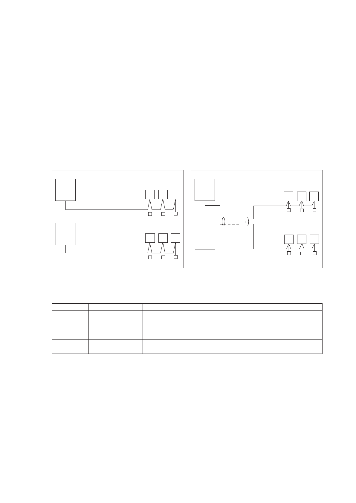
➀ Follow ordinance of your governmental organization for technical standard related to electrical equipment, wiring
regulations, and guidance of each electric power company.
➁ Wiring for control (hereinafter referred to as transmission line) shall be (5cm or more) apart from power source wiring so
that it is not influenced by electric noise from power source wiring. (Do not insert transmission line and power source wire
in the same conduit.)
➂ Be sure to provide designated grounding work to outdoor unit.
➃ Give some allowance to wiring for electrical part box of indoor and outdoor units, because the box is sometimes removed
at the time of service work.
➄ Never connect 380~415V(220~240V )power source to terminal block of transmission line.If connected,electrical parts
will be burnt out
➅ Use 2-core shield cable for transmission line. If transmission lines of different systems are wired with the same multiple-
core cable, the resultant poor transmitting and receiving will cause erroneous operations.
Outdoor
unit
Indoor unit
Remote
controller
2-core cable
2-core cable
Outdoor
unit
Remote
controller
Indoor unit
Multiple-
core cable
Type of cable
Cable diameter
Remarks
Sheathed 2-core cable (unshielded)
CVV
0.3
~ 1.25mm
2
(0.75 ~ 1.25mm2) ✻1
More than 1.25mm
2
Shielding wire (2-core)
CVVS or CPEVS
When 10m is exceeded, use cables with
the same specification as transmission cables.
0.3 ~ 1.25mm
2
(0.75 ~ 1.25mm2) ✻1
Max length : 200m
Transmission cables M-NET Remote controller cables MA Remote controller cables
CVVS : PVC insulated PVC jacketed shielded control cable
CPEVS : PE insulated PVC jacketed shielded communication cable
CVV : PV insulated PVC sheathed control cable
—
✻
1 Connected with simple remote controller.
- 18 -
™™
Restrictions
[1] Electrical Work & M-NET control
1. Attention
2. Types of control cable
Page 21
00
00
101
Main
00
201
201
201
202
000
247
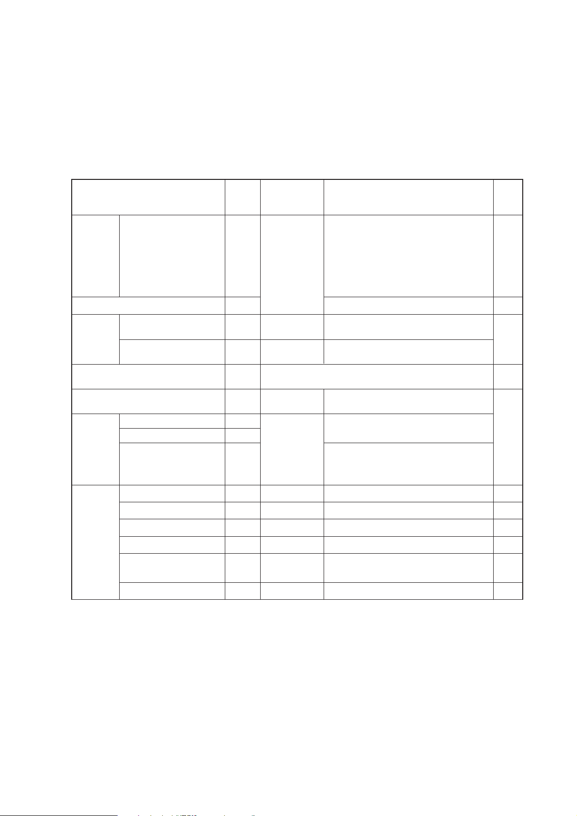
Address (1) setting varies depending on the system configuration. See “[3] Examples of system connection”
section for details.
Unit or controller Symbol
Address
Setting method
setting range
Indoor unit Main/sub units IC
Lossnay LC
M-NET
remote
controller
Main remote controller RC
Sub remote controller RC
MA remote controller MA
Outdoor unit OC
System
controller
Group remote controller GR, SC
System remote controller SR, SC
ON/OFF remote controller AN, SC
ST, SCSchedule timer (for M-NET)
Centralized controller TR, SC
(Note 5)
LM adapter SC
0, 01~50
(Note 1)
101~150
151~200
(Note 2)
0, 51~100
(Note 1, 3, 4)
52~100
(Note 3, 4)
201~250
201~250
201~250
201~250
0, 201~250
201~250
Notes:
Factory
setting
Type and method of switch setting
Switch setting vary depending on the system configuration. Make sure to read “[3] Examples of system connection”
before conducting electrical work. Turn off the power before setting the switch. Operating the switch while the unit is
being powered will not change the setting, and the unit will not properly function.
1. Address setting is not required for a single refrigerant system (with a few exception).
2. When setting M-NET remote controller address to “200,” make it “00.”
3. When setting the outdoor unit and outdoor auxiliary unit address to “100,” make it “50.”
4. When an address in a system overlapped with the outdoor unit or BC controller (Main) address of other refrigerant system,
choose an another address within theset range that is not in use (with a few exceptions).
5. When controlling the K-control units;
(1) A K-transmission converter (Model name: PAC-SC25KA) is required. To set the address for the K-transmission converter,
set it to thelowest address of the K-control unit to be controlled + 200.
(2) Set the address of the system controller (G-50A) to “0.” The K-control unit can only be controlled by the system controller
with theaddress “0.”
(3) To control both K-control unit and M-NET model unit, make the address of the K-control unit larger than that of the indoor
unit of M-NET model.
Group-register on the system controller so that the group No. and the lowest address of the K-controlled indoor units
belonging to thegroup will be identical.
Use the address that equals the sum of the smallest indoor
unit address in the same refrigerant system and 50.
Use the address that equals the sum of the smallest
address of the indoor unit out of all the indoor units
that are connected to the BC controller and 50.
When a sub BC controller is connected, the automatic
start up function will not be available.
Auxiliary
units
Hex. unit
BC controller (Sub)
OS
BC
BS
Use the address that equals the sum of the address of the
outdoor unit in the same refrigerant system and 1.
BC controller (Main)
Choose any number within the range of addresses shown left.
However when using with the upper SC setting, or wishing to
control the k-control units, set to “0.”
Assign the smallest address to the indoor unit to
become the main unit within the same group, and
then use sequential numbers to assign an address
to all the indoor units in the group. (Note 5)
If applicable, set the sub BC controllers in an R2
system in the following order:
(1)
Indoor unit to be connected to the main BC controller
(2)
Indoor unit to be connected to No.1 sub BC controller
(3)
Indoor unit to be connected to No.2 sub BC controller
Set the address so that (1) < (2) < (3)
Assign any unused address after setting all indoor units.
Set to the lowest address of the indoor main unit
within the same group + 150.
Set to the lowest No. of the group to be controlled + “200.”
Set to the lowest No. of the group desired tobe controlled + “200.”
Choose any number within the range of addresses shown left.
Choose any number within the range of ad-dresses shown left.
Choose any number within the range of addresses shown left.
Set to the lowest address of the indoor main unit
within the same group + 100.
No address setting required. (When operating with 2 remote controllers,
the main/sub selector switch must be set.
- 19 -
[2] Types of Switch Setting and Address Setting
1. Switch setting
2. Address setting
Page 22
- 20 -
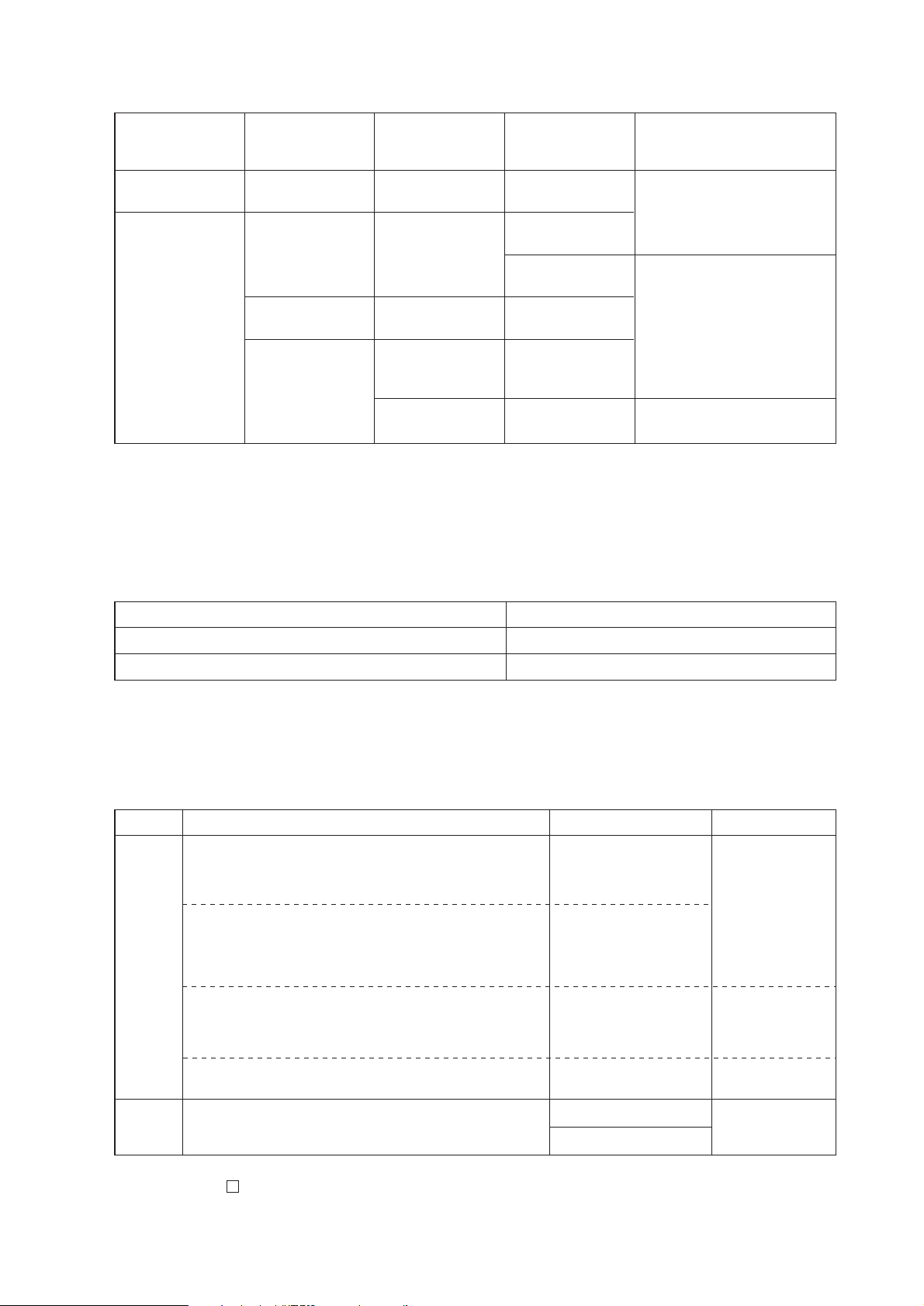
System
Configuration
Single refrigerant
system
___
_
Multiple refrigerant
system
Connection with
the system
controller
Power supply unit
for the
transmission lines
Unnecessary
Unnecessary (Note2)
(Supplied from the
outdoor unit)
Applicable
Grouping operation
of different
refrigerant systems
n/a
applicable
applicable // n/a
applicable // n/a
applicable // n/a
The setting of the power supply
selecting connector
Use CN41 as is (Factory setting)
Replace the CN41 with CN40 on
only one of the outdoor units.
✻
Connect the S terminal of the TB7
(terminal block on the outdoor
unit) on the outdoor unit whose
CN41 was replaced with CN40 to
the earth terminal of the electric
box.
Use CN41 as is (Factory setting)
n/a
Connected with the
indoor units
Connected with the
centralized system
Notes:
1. Will limit the total connectable units in the refrigerant system.
2. The need for a power supply unit for the transmission lines depends on the system configuration. Refer to “ DATA BOOK ” for
more details.
Setting the power supply selecting connector for the outdoor unit (Factory setting: CN41 is connected.)(2)
System configuration Setting of the centralized controller switch (SW 2-1)
Connection system with the system controller n/a Leave it to OFF. (Factory setting)
Connection system with the system controller applicable (Note 1) ON
Note:
1. When connecting only the LM adapter, leave SW2-1 to OFF.
Note:
1.
Refer to section “ 7 [2] 12. Demand control ” for detailed information on demand control settings.
Setting the centralized control switch on the outdoor unit (factory setting: SW2-1 OFF )(3)
Category
Output
Input
Usage
Cooling operation is disabled (thermo OFF) by the external
input to the outdoor units.
✻ Can be used as an on-demand control for each refrigerant
system.
Quiet operation of outdoor units is run with an external input to
the outdoor units.
(Night mode can be run under the following conditions: Outdoor
air temperature below 30
˚C when running a cooling operation
and above 3˚C when running a heating operation.)
Forces the outdoor units to run a fan operation by receiving the
snow signal from the snow sensor.
The operation mode can be switched between cooling and
heating with an external input to the outdoor units.
Outdoor units’ signal output
✻ Can be used as a device that displays the operation status
✻ Can run an interlocking control operation with external devices
Function
Demand (level)
Night mode or Demand
(Level) ✻
Note1
Snow sensor
Signal input (level)
You can switch the operation mode between cooling and
heating by input from the outside to the outdoor unit.
Auto-changeover
Compressor in operation
Abnormal operation status
CN3S
CN3N
CN3D
CN51
Terminal to be used
Various types of control using the connectors on the outdoor unit for input-output signal
(various types of connections with optional parts)
(4)
Page 23
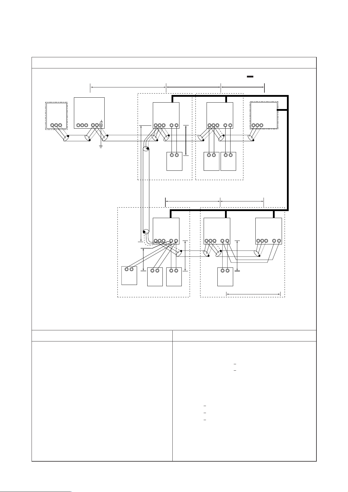
IC
TB5 TB
15
12
00
IC
TB5 TB
15
12
00
A1 B2
MA
A1 B2
MARC
TB5
00
IC
TB5
12
TB
15
IC
TB5 TB
15
12
0000
IC
TB5 TB
15
12
00
A1 B2
MA
A1 B2
MA
A1 B2
MA
MA
m1
L11
m2
L3 L4
L12 L13
m3
m5
m4
NO
NO
L2
A1 B2
A1 B2
a. Indoor/outdoor transmission line
Farthest length (1.25mm2 or more)
L2 + L3 + L4 200m
L2 + L11 + L12 + L13 200m
b. Centralized control transmission line
No connection is required.
c. MA remote controller wiring
Total length (0.3 ~ 1.25mm2)
m1 200m
m2 + m3 200m
m4 + m5 200m
Note 1. For the connection to the terminal block of compact
remote controller, employ wire with a diameter of 0.75
~ 1.25mm
2
Control wiring example
Group
Prohibited items Allowable length
1. M-NET and MA remote controllers can not be connected to-
gether to the indoor unit within the same group.
2. MA remote controller of 3 units or more can not be connected
to the indoor unit within the same group.
3. When the total number of indoor units exceeds 26 units In-
cluding that above Type 200, a transmission booster is re-
quired.
4. In the case when start/stop input (CN32, CN51, CN41) is used
by indoor group operation, the “Automatic address set-up”
can not be employed. Please refer to 1. (2) “ Manual address
set-up.”
5. For the connection of LOSSNAY with more than 2 units in a
single refrigerant system, refer to the following “Connection
of 2 LOSSNAY units in refrigerant system.”
Interlocking with ventilation
– Example to use shielded wire –
Group
Group
Group
LC
≤
≤
≤
≤
≤
S
M1M2
S
M1M2
S
M1M2
S
M1M2
S
M1M2
S
M1M2
OC
TB3
TB7
00
OS
TB3
S
(00)
S
M1M2 M1M2M1M2
- 21 -
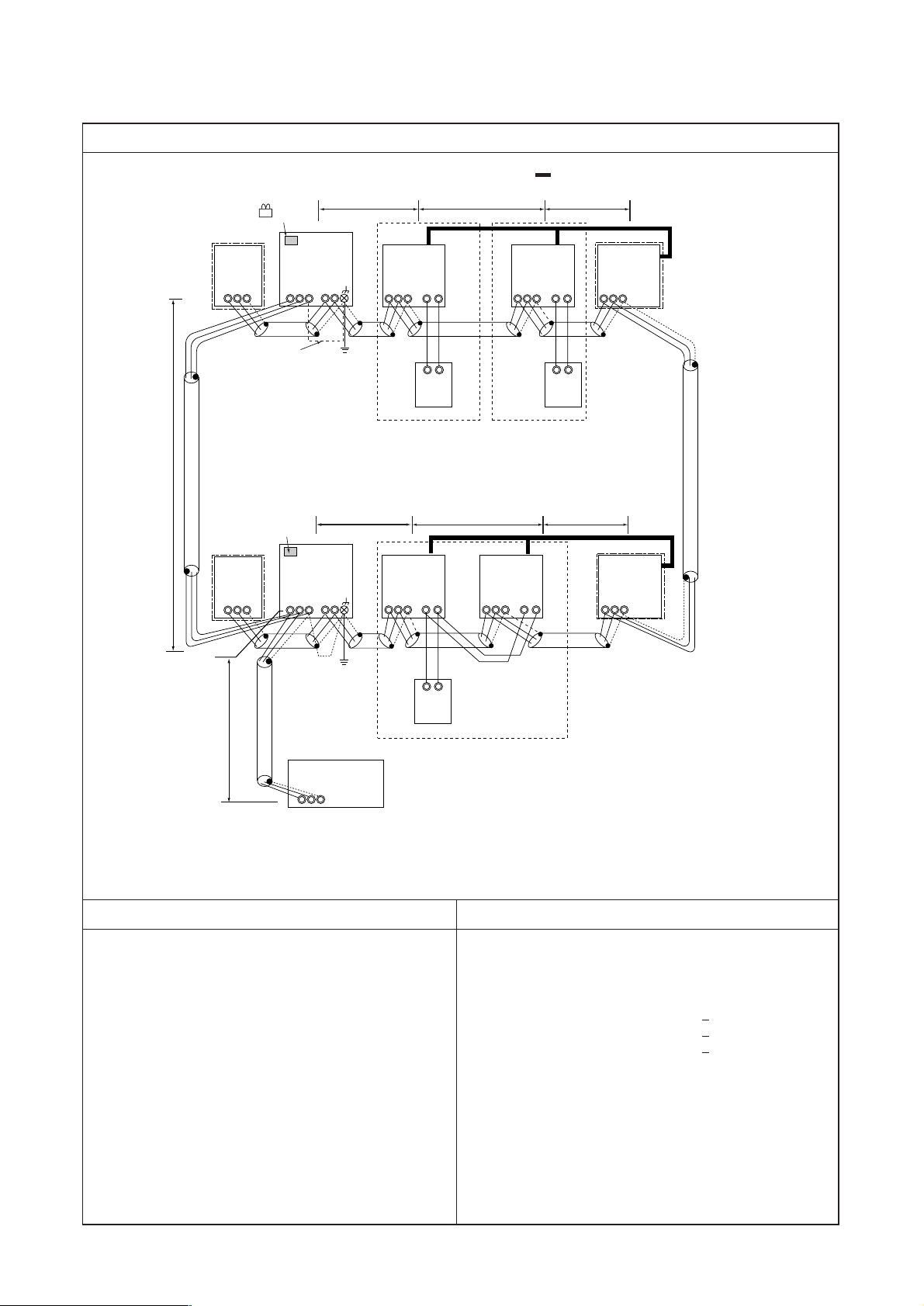
[3] Examples of system connection
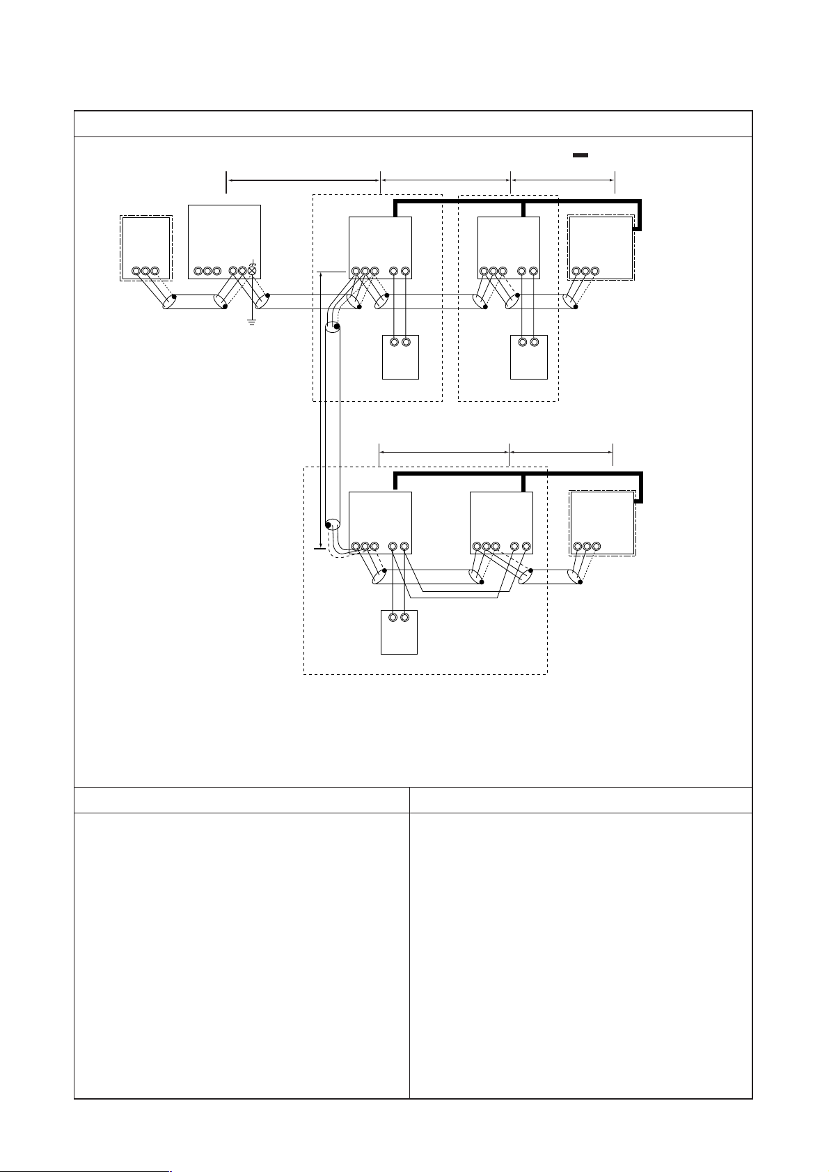
1. System using MA remote controller
(1) In the case of single refrigerant system (Automatic address set-up)
Page 24
Wiring method • Address setting method
a. Indoor/outdoor transmission line
Apply jumper wiring connection between M1, M2 terminals of the indoor/outdoor transmission line terminal block
(TB3) on the outdoor unit (OC) and that of indoor/outdoor transmission line terminal block (TB5) on each indoor
unit (IC). (with non-polarity two wires)
❉ When the transmission line is long or noise sources are located near the unit, recommend to use shielded wire.
Connection of shielded wire:
For the earth of shielded wire, apply jumper wiring connection between the earth screw of OC and the S-terminal of
IC terminal block (TB5).
b. Centralized control transmission line
Connection is not required.
c. MA remote controller wiring
Connect the 1, 2 terminals of MA remote controller wiring terminal block (TB15) on IC to the terminal block of MA
remote controller (MA). (with non-polarity two wires)
❉ MA remote controller can be connected to A-type indoor unit or later.
For 2-remote controller operation:
To employ 2-remote controller operation, connect 1, 2 terminals of the terminal block (TB15) on IC to the terminal
block of two MA remote controllers.
❉ Set the main/sub selector switch of one MA remote controller to the sub remote controller. (For the setting method,
see the installation manual of MA remote controller.)
For indoor group operation:
For the group operation of IC, connect 1, 2 terminals of the terminal block (TB15) on all ICs within the same group,
and connect 1, 2 terminals of the terminal block (TB15) on another IC to the terminals of MA remote controller.
(with non-polarity two wires)
❉ To operate the indoor units with different function in the same group, refer to 1. (2).
d. LOSSNAY connection
Apply jumper wiring to connect M1, M2 terminals of the terminal block (TB5) on IC to the indoor/outdoor
transmission terminal block (TB5) on LOSSNAY (LC). (with non-polarity two wires)
❉ Linked and registered automatically with all indoor units within a refrigerant system.
❉ Please refer to the 1. (2) “Manual address set-up,” when interlocking partial indoor units with Lossnay, using
Lossnay alone without interlocking, interlocking indoor units and Lossnay for over 16 units within a refrigerant
system, or connecting LOSSNAY for over 2 units in a refrigerant system.
e. Switch setting
Address setting is not required.
Order
Unit or controller
Address
Setting method Caution
Factory
setting range
setting
Main unit IC
Not required – 00
1 Indoor unit
Sub unit IC
2 LOSSNAY LC Not required –
3
MA remote
Main uni
Hex. unit
t MA Not required –
Main
controller
Sub unit
Comp. unit
MA Sub unit
4 Outdoor unit OC
Not required –
5 Sub unit OS
• Refer to 1. (2) to operate indoor units
with different function in the same
group.
Set with main/sub
selector switch.
00
00
- 22 -
Page 25
L2
IC
TB5 TB
15
12
01
IC
TB5 TB
15
12
02
A1 B2
MA
A1 B2
MA
TB5
05
IC
TB5
12
TB
15
IC
TB5 TB
15
12
0403
TB5
06
A1 B2
MA
L11
L3 L4
L12 L13
a. Indoor/outdoor transmission line
The same as 1. (1)
b. Centralized control transmission line
No connection is required.
c. MA remote controller wiring
The same as 1. (1)
Control wiring example
Group
Prohibited items Allowable length
1. M-NET and MA remote controllers can not be connected to-
gether to the indoor unit within the same group.
2. MA remote controller of 3 units or more can not be connected
to the indoor unit within the same group.
3. When the total number of indoor units exceeds 26 units in-
cluding that above Type 200, a transmission booster is re-
quired.
Interlocking with ventilation
– Example to use shielded wire –
Group
Group
LC
LC
S
M1M2
S
M1M2
S
M1M2
S
M1M2
S
M1M2
S
M1M2
S
M1M2
OC
TB3
TB7
51
OS
(52)
TB3
S
M1M2 M1M2
- 23 -
1. System using MA remote controller
(2) In the case of single refrigerant system connecting 2 or more LOSSNAY units (Manual address set-up)
Page 26
- 24 -
1 Indoor unit
2 LOSSNAY
3
MA remote
controller
4 Outdoor unit
Main unit
Sub unit
Main uni
t
Sub uni
Comp. unit
Hex. unit
t
IC
LC
MA
MA
OC
01 ~ 50
01 ~ 50
Not required
Not required
51 ~ 100
Wiring method • Address setting method
a. Indoor/outdoor transmission line
The same as 1. (1)
Connection of shielded wire:
The same as 1. (1)
b. Centralized control transmission line
No connection is required.
c. MA remote controller wiring
The same as 1. (1)
For 2-remote controller operation:
The same as 1. (1)
For indoor group operation:
The same as 1. (1)
d. LOSSNAY connection
Apply jumper wiring to connect M1, M2 terminals of the terminal block (TB5) on the indoor unit (IC) to the terminal
block (TB5) on Lossnay (LC). (with non-polarity two wires)
❉ The interlocking registration of the indoor unit and Lossnay from the remote controller is required. (For the regis-
tration method, see the installation manual of remote controllers.)
e. Switch setting
Address setting is required as listed below.
Order
Unit or controller
Address
Setting method Caution
Factory
setting range
setting
• Set the lowest address within
a same group to the indoor unit
desired to be the main unit.
Set to the main unit address
within a same group in serial order.
[Main unit +1, +2, +3, .... ]
Set any address after setting al
Set with main/sub selector
switch.
5 Sub unit OS Oundoor unit address + 1
l
indoor units.
–
00
00
Main
00
• When operating indoor
units with different function
within a same group, assign the indoor unit with the
most plenty of function to
the main unit.
• Set the address not to be
overlapped with the indoor
unit address.
• When setting address to
“100,” make it “50.”
The lowest address of indoor
unit within refrigerant system
+ 50
Page 27
- 25 -
IC
TB5 TB
15
12
01
IC
TB5 TB
15
12
03
A1 B2
MA
A1 B2
MA
TB5
06
IC
TB5
12
TB
15
IC
TB5 TB
15
12 12
0402
IC
TB5 TB15
05
A1 B2
MA
L3 L4
L23L22 L24
NO
NO
L2
m2
m3
a. Indoor/outdoor transmission line
Farthest length (1.25mm
2
or more)
L2 + L3 + L4 200m
L22 + L23 + L24 200m
b. Centralized control transmission line
Farthest length via outdoor unit (1.25mm
2
or more)
L2 + L3 + L4 + L31 + L22 + L23 + L24 500m
c. MA remote controller wiring
The same as 1. (1)
Control wiring example
Group
Prohibited items Allowable length
1. M-NET and MA remote controllers can not be connected together to the indoor unit within the same group.
2. MA remote controller of 3 units or more can not be connected
to the indoor unit within the same group.
3. Do not connect together the terminal blocks (TB5) of the indoor unit connected to different outdoor units.
4. Replacement of the power supply selecting connector (CN41)
on the outdoor unit should be done only on one outdoor unit.
5. Grounding of S-terminal of the centralized control terminal
block (TB7) on outdoor unit should be done only on one outdoor unit.
6. When the total number of indoor units exceeds 26 units including that above Type 200, a transmission booster is required.
Interlocking with ventilation
– Example to use shielded wire –
Group
Group
LC
≤
≤
≤
S
M1M2
S
M1M2
S
M1M2
S
M1M2
S
M1M2
S
M1M2
CN41→CN40
Replace
OC
TB3
TB7
51
OC
TB3
TB7
52
S
(54)
OS
S
(53)
L31
OS
TB3
Leave CN41
as it is.
TB3
Connect
S
M1M2 M1M2M1 M2
M1M2
S
M1M2 M1M2
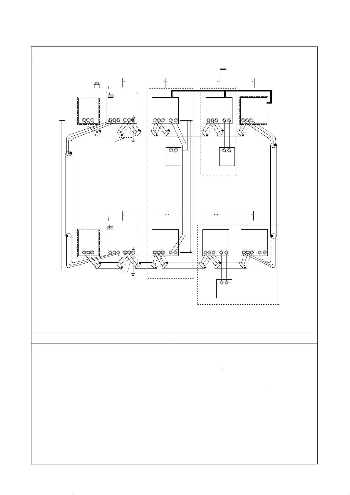
1. System using MA remote controller
(3) In the case of different refrigerant grouping operation
Page 28
- 26 -
Wiring method • Address setting method
a. Indoor/outdoor transmission line
Apply jumper wiring connection between M1, M2 terminals of the indoor/outdoor transmission line terminal block
(TB3) on the outdoor unit (OC) and that of indoor/outdoor transmission line terminal block (TB5) on each indoor
unit (IC). (with non-polarity two wires)
❉ Make sure to use shielded wire.
Connecting of shielded wire:
The same as 1. (1)
b. Centralized control transmission line
Apply jumper wiring between M1, M2 terminals of centralized control transmission line terminal blocks (TB7) on
each OC. For one OC only, replace the power selecting connector (CN41) with (CN40).
❉ Make sure to use shielded wire.
Connecting of shielded wire:
Apply jumper wiring to connect the shielded earth to S-terminal of the terminal block (TB7) on each OC. Connect
Sterminal of the terminal block (TB7) on the one OC with (CN40) replaced to the earth screw ( ) of the electrical
parts box.
c. MA remote controller wiring
The same as 1. (1)
For 2-remote controller operation:
The same as 1. (1)
For indoor unit group operation:
The same as 1. (2)
d. LOSSNAY connection
The same as 1. (2)
e. Switch setting
Address setting is required as follows.
1 Indoor unit
2 LOSSNAY
3
MA remote
controller
4 Outdoor unit
Main unit
Sub unit
Main unit
Sub unit
IC
LC
MA
MA
OC
01 ~ 50
01 ~ 50
Not required
Sub unit
51 ~ 100
• Set the address not to be
overlapped with the indoor
unit address.
• When setting address to
“100,” make it “50.”
Order
Unit or controller
Address
Setting method Caution
Factory
setting range
setting
• Set the lowest address within
a same group to the indoor unit
desired to be the main unit.
Set to the main unit address
within a same group in serial order.
[Main unit +1, +2, +3, .... ]
Set any address after setting all
indoor units.
–
Set by the main/sub selector
switch.
The lowest address of indoor
unit within refrigerant system
+ 50
00
00
Main
Hex. unit
Comp. unit
5 Sub unit OS Oundoor unit address + 1
00
Page 29
- 27 -
IC
TB5 TB
15
12
01
IC
TB5 TB
15
12
02
A1 B2
MA
A1 B2
MA
TB5
05
IC
TB5
12
TB
15
IC
TB5 TB
15
12
0403
TB5
06
A1 B2
MA
L3 L4
L23 L24
NO
L2
L22
NO
a. Indoor/outdoor transmission line
The same as 1. (3)
b. Centralized control transmission line
Farthest length via outdoor unit (1.25mm2 or more)
L32 + L31 + L2 + L3 + L4 500m
L32 + L22 + L23 + L24 500m
L2 + L3 + L4 + L31 + L22 + L23 + L24 500m
c. MA remote controller wiring
The same as 1. (1)
Control wiring example
Group
Prohibited items Allowable length
1. M-NET and MA remote controllers can not be connected together to the indoor unit within the same group.
2. MA remote controller of 3 units or more can not be connected
to the indoor unit within the same group.
3. Do not connect together the terminal blocks (TB5) of the indoor unit connected to different outdoor units.
6. When the total number of indoor units exceeds 26 units Including that above Type 200, a transmission booster is required.
Interlocking with ventilation
– Example to use shielded wire –
Group
Group
LC
LC
Notes:
1. Leave SW2-1 as “OFF” when connecting LM adapter only.
2. LM adapter requires the power source of 1-phase AC 230V
Note 1
.
≤
≤
≤
4. Replacement of the power supply selecting connector (CN41)
on the outdoor unit should be done only on one outdoor unit.
5. Grounding work is required for S-terminal of the centralized
control transmission block (TB7) on one outdoor unit onl
CN41→CN40 Replace
SW2-1 OFF→ON
y.
S
M1M2
S
M1M2
S
M1M2
S
M1M2
S
M1M2
S
M1M2
OC
TB3
TB7
51
OS
S
(52)
OC
TB3
TB7
53
(54)
System controller
S
L31
L32
Note 2
TB3
TB3
OS
S
M1M2 M1M2
S
S
M1M2 M1M2
M1M2
M1M2
M1M2
Connect
Note 1
Leave CN41 as it is.
SW2-1 OFF→ON
1. System using MA remote controller
(4) In the case of connecting system controller to centralized control transmission line
Page 30

- 28 -
Wiring method • Address setting method
a. Indoor/outdoor transmission line
The same as 1. (3)
Connection of shielded wire:
The same as 1. (1)
c. MA remote controller wiring
The same as 1. (1)
For 2-remote controller operation:
The same as 1. (1)
For indoor group operation:
The same as 1. (1)
d. LOSSNAY connection
Apply jumper wiring to connect M1, M2 terminals of the terminal block (TB5) on (IC) to the terminal block (TB5)
on the indoor/outdoor transmission line terminal block (TB5) on Lossnay (LC). (with non-polarity two wires)
❉ The interlocking registration of the indoor unit and LOSSNAY from the system controller is required. (For the
registration method, see the installation manual of the system remote controllers.)
When connecting ON/OFF remote controller and LM adaptor only, the interlocking registration from the remote
controller is required.
e. Switch setting
Address setting is required as listed below.
1 Indoor unit
2 LOSSNAY
3
MA remote
controller
4 Outdoor unit
Main unit
Sub unit
Main unit
Sub unit
IC
LC
MA
MA
OC
01 ~ 50
01 ~ 50
Not required
Sub unit
• Set the address not to be
overlapped with the indoor
unit address.
• Conduct initial setting by the
system controller with the
same setting detail of indoor
unit applied in MA remote
controller wiring.
• When setting address to
“100,” make it “50.”
Order
Unit or controller
Address
Setting method Caution
Factory
setting range
setting
• Set the lowest address within
a same group to the indoor unit
desired to be the main unit.
Set to the main unit address
within a same group in serial order.
[Main unit +1, +2, +3, .... ]
Set any address after setting all
indoor units.
–
Set by the main/sub selector
switch.
The lowest address of indoor
unit within refrigerant system
+ 50
00
00
Main
b. Centralized control transmission line
Apply jumper wiring between M1, M2 terminals of centralized control transmission line terminal blocks (TB7) on
each OC. On one OC only, replace the power selecting connector (CN41) with (CN40). Set the centralized control
switch (SW2-1) on the main board of all outdoor units to “ON.”
❉ Make sure to use shielded wire.
Connection of shielded wire:
Apply jumper wiring to connect the shielded earth to S-terminal of the terminal block (TB7) on each OC. Connect S-
terminal of the terminal block (TB7) on one OC with (CN40) connected to the earth screw ( ) of the electrical
parts box.
51 ~ 100
Hex. unit
Comp. unit
5 Sub unit OS Oundoor unit address + 1
00
Page 31

- 29 -
IC
TB5 TB
15
12
01
IC
TB5 TB
15
12
02
A1 B2
MA
A1 B2
MA
TB5
05
IC
TB5
12
TB
15
IC
TB5 TB
15
12
0403
TB5
06
A1 B2
MA
L3 L4
L23 L24
L2
L22
NO
a. Indoor/outdoor transmission line
Farthest length (1.25mm2 or more)
L2 + L3 + L4 200m
L22 + L23 + L24 200m
L25 200m
b. Centralized control transmission line
Farthest length via outdoor unit (1.25mm2 or more)
L25 + L31 + L2 + L3 + L4 500m
L2 + L3 + L4 + L31 + L22 + L23 + L24 500m
c. MA remote controller wiring
The same as 1. (1)
Control wiring example
Group
Prohibited items Allowable length
1. M-NET and MA remote controllers can not be connected together to the indoor unit within the same group.
2. MA remote controller of 3 units or more can not be connected
to the indoor unit within the same group.
3. Do not connect together the terminal blocks (TB5) of the indoor unit connected to different outdoor units.
4. Replacement of the power supply selecting connector (CN41)
on the outdoor unit should be done only on one outdoor unit.
5. Grounding work is required for S-terminal of the centralized
control transmission block (TB7) on one outdoor unit only.
6. The system controller connectable to the indoor/outdoor transmission line counts for 3 sets maximum. While G-50 counts
for only 1 set
7. When the total number of indoor units exceeds 26 sets, th e
system controller may not be connected to the indoor/outdoor transmission line.
8. When the total number indoor units exceed 18 sets and they
includes Type 200 or above, the system controller may not
be connected to the indoor/outdoor transmission line.
Interlocking with ventilation
– Example to use shielded wire –
Group
Group
LC
LC
Note 1. LM adaptor may not be connected to indoor/outdoor transmission line.
≤
≤
≤
≤
≤
NO
CN41→CN40 Replace
SW2-1 OFF→ON
Leave CN41 as it is.
SW2-1 OFF→ON
S
M1M2
S
M1M2
S
M1M2
S
M1M2
S
M1M2
S
M1M2
OC
TB3
TB7
51
OS
(52)
OC
TB3
TB7
53
(54)
L31
Connect
System controller
Note 1
L25
TB3
OS
TB3
S
M1M2
S
M1M2 M1M2
S
M1M2
S
M1M2 M1M2
S
M1M2
1. System using MA remote controller
(5) In the case of connecting system controller to indoor/outdoor transmission line (excluding LM adaptor)
Page 32

- 30 -
Wiring method • Address setting method
a. Indoor/outdoor transmission line
Apply jumper wiring connection between M1, M2 terminals of the indoor/outdoor transmission line terminal block
(TB3) on the outdoor unit (OC) and that of indoor/outdoor transmission line terminal block (TB5) on each indoor
unit (IC). (with non-polarity two wires)
❉ Make sure to use shielded wire.
Connection of shielded wire:
For the grounding of shielded wire, apply jumper wiring between the grounding screw of OC, S-terminal of the
terminal block (TB3), and S-terminal of the system controller.
b. Centralized control transmission line
Apply jumper wiring between M1, M2 terminals of centralized control transmission line terminal blocks (TB7) on
each OC. On one OC only, replace the power selecting connector (CN41) with (CN40). Set the centralized control
switch (SW2-1) on the main board of all outdoor units to “ON.”
❉ Make sure to use shielded wire.
Connection of shielded wire:
Apply jumper wiring to connect the shielded earth to S-terminal of the terminal block (TB7) on each OC. Connect S-
terminal of the terminal block (TB7) on one OC with (CN40) connected to the earth screw ( ) of the electrical
parts box.
c. MA remote controller wiring
The same as 1. (1)
For 2-remote controller operation:
The same as 1. (1)
For indoor unit group operation:
The same as 1. (2)
d. LOSSNAY connection
Apply jumper wiring to connect A, B terminals of the terminal block (TB5) on (IC) to the terminal block (TB5) on the
indoor/outdoor transmission line terminal block (TB5) on Lossnay (LC). (with non-polarity two wires)
❉ The interlocking registration of the indoor unit and Lossnay is required from the system controller. (For the
registration method, see the instruction manual of system controller.)
To connect ON/OFF remote controller only, interlocking registration from the remote controller is required.
e. Switch setting
Address setting is required as follows.
1 Indoor unit
2 LOSSNAY
3
MA remote
controller
4 Outdoor unit
Main unit
Sub unit
Main unit
Sub unit
IC
OC
LC
MA
MA
01 ~ 50
01 ~ 50
Not required
Sub unit
• Set the address not to be
overlapped with the indoor
unit address.
• Conduct initial setting by the
system controller with the
same setting detail of indoor
unit applied in MA remote
controller wiring.
• When setting address to
“100,” make it “50.”
Order
Unit or controller
Address
Setting method Caution
Factory
setting range
setting
• Set the lowest address within
a same group to the indoor unit
desired to be the main unit.
Set to the main unit address
within a same group in serial order. [Main unit +1, +2, +3,]
Set any address after setting all
indoor units.
–
Set by the main/sub selector
switch
.
The lowest address of indoor
unit within refrigerant system
+ 50
00
00
Main
51 ~ 100
Hex. unit
Comp. unit
5 Sub unit OS Oundoor unit address + 1
00
Page 33

- 31 -
IC
TB5 TB
15
12
01
101
103
102
IC
TB5 TB
15
12
02
A1 B2
RC
A1 B2
RC
TB5
05
IC
TB5
12
TB
15
IC
TB5 TB
15
12
0403
TB5
06
A1 B2
RC
L3 L4
L23 L24
L2
L22
NO
Control wiring example
Group
Prohibited items Allowable length
Interlocking with ventilation
– Example to use shielded wire –
Group
Group
LC
LC
Note 1: If only the LM adaptor is connected, leave SW2-1 to OFF.
Note 2: LM adaptor requires single phase AC 230 V.
1. A group of indoor units cannot be connected to both M-NET
remote controller and MA remote controllers.
2. No more than 2 M-NET remote controllers can be connected
to a group of indoor units.
3. Do not connect the TB5’s (Terminal block) of the indoor
units that are connected to different outdoor units.
4. Replace CN41 (power supply switch connector on outdoor
units) on only one of the outdoor units.
5. Ground the S terminal of TB7 on only one of the outdoor
units.
6. Transmission line booster is necessary when the total
number of connected indoor units exceeds 20 (19 with 1 BC
and 18 with 1 BC and BS each).
7. Transmission line booster is necessary if the system
includes indoor units of 200 or higher and the total number
of indoor units exceeds 16 (15 with 1 BC and 14 with 1 BC
and BS each).
a. Indoor/outdoor transmission line
b. Centralized control transmission line
c. M-NET remote controller wiring
CN41→CN40 Replace
SW2-1 OFF→
NO
ON
Note 1
Leave CN41 as it is.
SW2-1 OFF→ON
The same as 2. (1)
The same as 1. (4)
The same as 1. (3)
S
M1M2
S
M1M2
S
M1M2
S
M1M2
S
M1M2
S
M1M2
OC
TB3
TB7
51
OS
(52)
OC
TB3
TB7
53
(54)
System controller
L31
L32
Note 2
TB3
TB3
OS
Note 1
Connect
S
M1M2 M1M2
S
M1M2
S
M1M2 M1M2
S
M1M2
S
M1M2
2. System Using the M-NET Remote Controller
(1) System with the system controller connected to the transmission lines for centralized control
Page 34

- 32 -
a. Indoor/outdoor transmission line
Connection of shielded wire:
b. Centralized control transmission line
c. M-NET remote controller wiring
The same as 1. (3)
For 2-remote controller operation:
The same as 1. (1)
Connection of shielded wire:
The same as 1. (4)
The same as 1. (4)
For a 2-remote-controller operation, connect each of the terminals M1 and M2 of the IC terminal block to the two RC
terminal blocks respectively.
Indoor unit group operation
To operate IC
’s as a group, connect the M1, M2 terminals of the terminal block on the main IC in the group with the
RC terminal block (with non-polar two wires)
❉M-NET remote controller can be connected at any point on the indoor/outdoor transmission line.
❉To run a group operation of indoor units that have different functions, select the unit with the greatest number
of functions as the main unit.
The same as 1. (4)
For indoor unit group operation:
d. LOSSNAY connection
M-NET remote controller wiring
Connect each of the M1 and M2 terminals of TB5 (indoor/outdoor transmission line terminal block) on the IC to the
terminals on the M-NET remote controller.
e. Switch setting
Address setting is required as follows.
1 Indoor unit
2 LOSSNAY
3
M-NET
remote
controller
4 Outdoor unit
Main unit
Sub unit
Main unit
Sub unit
IC
OC
LC
RC
RC
01 ~ 50
01 ~ 50
51 ~ 100
101 ~ 150
151 ~ 200
Order
Unit or controller
Address
Setting method Caution
Factory
setting range
setting
00
00
101
00
Starting with the number main unit
address +1, assign a sequential
number to each of the rest of the indoor units.
After all indoor units have received
an address, use any remaining number and assign it to the Lossnay
unit. units.
The smallest indoor unit address in
the same refrigerant system +50
The address of the main unit in the
same group +100
The address of the main unit in the
same group +150
• Assign the smallest address within
the group to the indoor unit to become the main unit.
• Make the initial setting of the
indoor unit group setting with
the system controller
(MELANS).
• The Lossnay address must not
overlap with the indoor unit address.
• 100
’s digit does not need to be
set.
• Set the address to “ 00 ” when
setting it to “ 200 ”.
• Set the address to “ 50 ” when
setting it to “ 100 ”.
Wiring method • Address setting method
Comp. unit
Hex. unit5 Sub unit OS
Oundoor unit address + 1
Page 35

- 33 -
IC
TB5 TB
15
12
01
IC
TB5 TB
15
12
02
IC
TB5 TB
15
12
04
104
IC
TB5 TB
15
12
06
A1 B2
MA
A1 B2
RC
A1 B2
MA
IC
TB5
12
TB
15
IC
TB5 TB
15
12
0503
L2
L22
L3 L4
L23 L24
105
A1 B2
RC
NO
a. Indoor/outdoor transmission line
The same as 1. (3)
b. Centralized control transmission line
The same as 1. (4)
c-1. MA remote controller wiring
The same as 1. (1)
c-2. M-net remote controller wiring
The same as 2. (1)
Control wiring example
Group
Prohibited items Allowable length
1. Make sure to connect the system controller.
2. M-NET and MA remote controllers can not be connected together to the indoor unit within a same group.
3. M-NET remote controller of 3 units or more can not be connected to the indoor unit within a same group.
6.
7.
8. When the total number of indoor units exceeds 20 sets, transmission line booster is required.
9. When the total number of indoor units exceed 16 sets and
they include Type 200 or above, the transmission line booster
is required.
– Example to use shielded wire –
Group
Group
Notes:
1. Leave SW2-1 as “OFF” when connecting LM adapter only.
2. LM adapter requires the power source of 1-phase AC 230V.
Group
Replacement of the power supply selecting connector (CN41)
on the outdoor unit should be done only on one outdoor unit.
Grounding work is required for S-terminal of the centralized
control transmission block (TB7) on one outdoor unit only.
4. MA remote controller of 3 units or more can not be connected
to the indoor unit within a same group.
5. Do not connect together the terminal blocks (TB5) of the indoor unit connected to different outdoor units.
NO
S
M1M2
S
M1M2
S
M1M2
S
M1M2
S
M1M2
S
M1M2
OC
TB3
TB7
51
OS
(52)
OC
TB3
TB7
53
(54)
System controller
L31
L32
Note 2
TB3
OS
TB3
S
M1M2 M1M2
S
M1M2
S
M1M2
S
M1M2 M1M2
S
M1M2
Connect
Note 1
CN41→CN40 Replace
SW2-1 OFF→ON
Note 1
Leave CN41 as it is.
SW2-1 OFF→ON
3. System where MA remote controller and M-NET remote controller coexist
Page 36

- 34 -
Indoor
unit
MA
remote
controller
Indoor
unit
M-NET
remote
controller
Wiring method • Address setting method
a. Indoor/outdoor transmission line
The same as 1. (3)
Connection of shielded wire:
The same as 1. (1)
b. Centralized control transmission line
The same as 1. (4)
Connection of shielded wire:
The same as 1. (4)
c-1. MA remote controller wiring, For 2-remote controller operation: , For indoor unit group operation:
The same as 1. (1)
c-2. M-NET remote controller, For 2-remote controller operation: , For indoor unit group operation:
The same as 2. (1)
d. Lossnay connection
The same as 1. (4)
e. Switch setting
Address setting is required as follows.
Operation
with MA
remote
controller
Operation
with M-NET
remote
ontroller
Lossnay
Outdoor unit
IC
MA
MA
IC
RC
RC
LC
OC
01 ~ 50
Not
required
Sub remote
controller
01 ~ 50
101 ~ 150
151 ~ 200
01 ~ 50
51 ~ 100
• Set lower address than that of
the indoor unit connected to
M-NET remote controller.
• Initially set the same setting
detail as that of indoor unit
group executed in the wiring
of MA remote controller with
system controller.
• Initially set the same setting
detail as that of indoor unit
group with system controller.
• 100 digits are not required to
set.
• When setting the address as
“200,” make it “00.”
• Set so that not duplicating with
the indoor unit addresses.
• When setting address to
“100,” make it “50.”
Order
Unit or controller
Address
Setting method Caution
Factory
setting range
setting
• Set the lowest address within
a same group to the indoor unit
desired to be the main unit.
Set to the main unit address
within a same group in serial order. [Main unit +1, +2, +3,]
–
Set by using the main/sub selector switch
• After setting the address of the
indoor unit to be operated with
MA controller, set the lowest
address among the same
group to the indoor unit desired
to be the main unit.
Set to the main unit address
within a same group in serial order. [Main unit +1, +2, +3,]
Main unit address inside a same
group + 100
Main unit address inside a same
group + 150
After setting all indoor units, set
any address.
The lowest address of indoor
unit within refrigerant system + 50
00
Main
00
101
00
00
Main
unit
Sub
unit
Main
unit
Sub
unit
Main
unit
Sub
unit
Main
unit
Sub
uni
Hex.
unit
Comp.
unit
t
1
2
3
4
Sub unit OS Oundoor unit address + 15
Page 37

- 35 -
L
H1(
Upper Comp. unit)
H
1’
(
Lower Comp. unit)
H2
A
A
BCD
a
b
c
d
h
e
1
5
23 4
1. Line branching system
For the piping connection, the end branching system is applied where the end of refrigerant piping from the outdoor unit is
branched and connected to each indoor unit. As the piping connection method, the indoor unit is applied with flare connection, outdoor unit gas piping is flange connection, and liquid piping is flare connection. For the branching, brazed connection
is applied.
Warning
Be careful not to leak refrigerant gas (R410A) near a fire. Refrigerant gas if touched a fire of gas oven and the like will
be decomposed to generate poisonous gas leading to gas-poisoning. Do not conduct welding work in a closed room.
Run a gas leak test after completing refrigerant piping work.
Note: The total model names downstream in the table below
represent that viewed from A-point in the above figure.
Comp. unit
Hex. unit
First branch
Indoor
Indoor Indoor Indoor
To downstream unit
Do not use a charging cylinder.
• Using a charging cylinder may cause the refrigerant to
deteriorate.
Do not use existing refrigerant piping.
• The old refrigerant and refrigerator oil in the existing piping
contains a large amount of chlorine which may cause the
refrigerantor oil of the new unit to deteriorate.
Store the piping to be used during installation indoors
and keep both ends of the piping sealed until just
before brazing.
(Store elbows and other joints in a plastic bag.)
• If dust, dirt, or water enters the refrigerant cycle,
deterioration of the oil and compressor trouble may result.
Caution
Caution
Caution
Do not use a refrigerant other than that indicated on
the equipment at installation or movement.
• Mixing of different refrigerant or air makes the refrigeration cycle
abnormal causing breakage and the like.
Warning
Caution
Indoor
Use refrigerant piping phosphorus deoxidized copper. In addition, be sure that the inner and outer surface of the pipes are clean and free of hazardous
sulphur, oxides, dust/dirt, shaving particles, oils,
moisture, or any other contaminant.
• Contaminants on the inside of the refrigerant piping may cause
the refrigerant residual oil to deteriorate.
Caution
Use liquid refrigerant to fill the system.
• If gas refrigerant is used to seal the system, the composition of
the refrigerant in the cylinder will change and performance may
drop.
Item Piping section Allowable value
Total piping length A + B + C + D + a + b + c + d +e Less than 300m
Length
Farthest piping length (L) A + B + C + D + e
Farthest piping length after first branch ( )
Comp. unit – Hex. unit
B + C + D + e Less than 40m
Upper Comp. unit H1 Less than 50m
Indoor –
Comp. unit
Lower Comp. unit H1’ Less than 40m
Indoor – Indoor h
E
Comp. unit – Hex. unit H2
Less than 15m
Less than 0.1m
Less than 150m
(Equivalent length:less than 175m)
Less than 10m
(Equivalent length:less than 12m)
E
Height
difference
[4] Restrictions on Refrigerant Piping Length
Page 38

- 36 -
Fan guard
Heat exchanger
Fan guard
Heat exchanger
££
Components of the Outdoor Unit
[1] Appearance of the Components and Refrigerant Circuit
< Compressor unit >
[ Front view of the unit ]
[ Rear view of the unit ]
Page 39

- 37 -
Pressure
switch
(63H1)
Accumulator
Inverter
compressor
(No.1)
Oil balance tube
Inverter compressor
(No.2)
Pressure
switch
(63H2)
Check joint
(CJ3)
Oil separator (No.1)
Oil separator (No.2)
Check joint
(CJ4)
Low-pressure
check joint
High-pressure
check joint
2-way valve (SV5c)
Check valve (CV3)
Liquid-side ball valve
(connected to indoor unit)
Gas-side ball valve
(connected to indoor unit)
Gas-side ball valve
(connected to Hex. unit)
Drier
4-way valve (21S4b)
High-pressure pressure sensor (63HS)
2-way valve (SV5b)
4-way valve (21S4a)
Low-pressure pressure sensor (63LS)
4-way valve
(21S4c)
Liquid-side ball valve
(connected to Hex. unit)
< Compressor unit >
[ Front view of the refrigerant circuit – Right ]
[ Rear view of the refrigerant circuit – Left ]
Page 40

- 38 -
Accumulator
Oil tank
Linear expansion
valve (LEV1)
4-way valve (21S4a)
4-way valve (21S4b)
4-way valve (21S4c)
Sub cool coil
Accumulator
< Compressor unit >
[ Front view of the unit – Right ]
[ Rear view of the unit – Left ]
Page 41

- 39 -
Fan guard
Heat exchanger
Fan guard
Heat exchanger
< Heat exchanger unit >
[ Front view of the unit ]
[ Rear view of the unit ]
Page 42

- 40 -
Liquid pipe
(connected to Comp. unit)
Control box
Thermistor (TH5b)
Heat exchanger
Gas pipe
(connected to Comp. unit)
< Heat exchanger unit >
[ Refrigerant circuit ]
Page 43

- 41 -
No.1 INV board
No.2 INV board Main board
Power supply terminal
block (TB1)
Indoor/outdoor
transmission
terminal block
(TB3)
Transmission line
terminal block
for centralized control
(TB7)
Relay board
Smoothing capacitor
(C11, C12)
Resistor
(R13, R14)
Resistor
(R23, R24)
Gate amp board2
(G/A board)
Gate amp board1
(G/A board)
Electromagnetic
contactor (52C2)
Electromagnetic
contactor (52C1)
Noise filter
(ACNF1)
Rush current
protection resistor
(R11, R12)
Noise filter
(ACNF2)
Diode stack
(DS2)
Smoothing capacitor
(C21, C22)
Rush current
protection resistor
(R21, R22)
Diode stack
(DS1)
FAN board
[2] Control Box
< Compresser unit >
[ Appearance ]
[ Under the circuit board cover ]
Page 44

DCL2
DCL1
Choke coil
(L1,L2)
Transformer
Filter board
- 42 -
[ Rear view of the control box ]
[ Rear view of the circuit board cover ]
Page 45

- 43 -
Smoothing capacitor
(C1, C2)
Resistor
(R2, R3)
Electromagnetic
contactor (52F)
Transformer for
FAN board (T02)
Noise filter
(NF)
Diode stack
(DS)
Rush current
protection resistor
(R1)
FAN board DCL Control board
Transformer for
control board (T01)
Power supply
terminal
block (TB1)
Indoor/outdoor
transmission
terminal block
(TB3)
< Heat exchanger unit >
Page 46

- 44 -
CNVCC1
Controlled
source input
1–2
DC30V
1–3
DC30V
4–5
DC7V
4–6
DC12V
7–8
DC7V
CNRS3BLD2
CNAC3
Power output
3
L1
1
L2
CN20
Power intput
5
L1
CN21
Power intput
3
L2
1
N
LD1
Service LED
SW5 SW4 SW3 SW2
SWU2 SWU1
SW1
CNLVB
CN3S
CN3D
CN3N
CNRS3A CNS1 CNS2 CN40 CN41
CNRT1
CNOUT1
CN52C
Control for
52C1
CN51
3–4
Compressor
ON/OFF
3–5
Trouble
CN38
[3] Circuit Board
1. Main board
Page 47

- 45 -
CNVCC1
Power supply
1–2
DC30V
1–3
DC30V
4–5
DC7V
4–6
DC12V
7–8
DC7V
CN15V2
Power supply
for IPM control
F02CNVDC
SW1
SW2
CN52C
CNFAN CNRS1 CNRS2
Serial
transmission
for MAIN board
CNCT2
CNAC2
Power Source
5
L2
3
N
1
G
CNTH
CNCT
CNDR2
2. INV board
Page 48

- 46 -
4. Relay board
CNVDC
DC bus voltage input
1–3
LED1
LED2
SW2
CNTRIPM (back)
CNINV Fan motor output Fuse CNRS2
3. FAN board
CN01
CH12 output
3–5
AC220~240V
CNAC1
CH12 power input
1–3
AC220~240V
CNIN
relay driving input
CNX10
Page 49

- 47 -
CNFG CNL2CNL1
CNOUT
Controlled
source output
CNIN
Controlled
source input
5. Filter board
CNDR1
CN15V1
CNDC1 CNDC2
CNIPM1
6. G/A board
Page 50

CN3T
Power input
CN2M for
M-NET transmission
CND
Power input (AC220~240V)
1 L1 phase
3 N phase
Address switch
CN29
TH5b
Piping temperature
Heat exchanger
unit No. switch
Dipswitch
CNT
Primary transformer
1–3 AC220~240V
CNP
52F output
1
–3 AC220~240V
LED2
Service LED
LED1 lit during
power reception
CN30,CN21,CN7V
Serial communication input from
and output to FAN board
- 48 -
7. Controller board (heat exchanger unit)
Page 51

- 49 -
Function/specification
Remote controller address setting
Not required Required
Indoor/outdoor unit address
setting
Not required (applicable only in the case
of single refrigerant systems)(Note 3)
Required
Wiring method Non-polar 2 wires
✻
Daisy-chain the indoor units with non-polar
2 wires when running a group operation.
Non-polar 2 wires
Installation location of
remote controller
Connectable to any indoor unit in the
group
Connectible at any point on the
indoor/outdoor transmission line
Interlocking with the
ventilation unit
Each indoor unit can individually be
interlocked with a ventilation unit.
(Registered on the remote controller in
the same group)
Each indoor unit can individually be
interlocked with a ventilation unit.
(Registered on the remote controller)
Making group changes
(Note 1) MA remote controller includes MA remote controllers, MA compact remote controllers, and wireless remote controllers.
(Note 2) M-NET remote controller includes ME remote controllers and compact remote controllers.
(Note 3) Depending on the system configuration, even a single refrigerant system may require an address setting.
(Note 4) Either an MA remote controller or an M-NET remote controller can be connected to a group of multiple-refrigerant systems
or when a system controller is connected.
(Note 1) M-NET remote controllers and MA remote controllers cannot both be connected to the same group of indoor units.
(Note 2) A system controller must be connected to a system that has both MA remote controllers and M-NET remote controllers.
MA remote controller wires between
indoor units require rewiring.
Indoor unit and remote controller
addresses must be changed, or the
registration information must be changed
using MELANS.
M-NET(ME)Remote Controller (Notes 2, 4)MA remote controller (Notes 1, 4)
MA remote controller (Notes 1, 2)
< A system using an MA remote controller > < System using an M-NET remote controller >
• Low chances of system expansion and grouping
changes are expected.
• Grouping (floor plan) has been decided at the
time of installation.
• High chances of centralized installation of remote
controllers, system expansion, and grouping changes.
• Grouping (floor plan) has not been decided at the
time of installation.
• Direct connection of the remote controller to the
Lossnay inside the heater-humidifier.
M-NET (ME) remote controller (Notes 1, 2)
MA remote controller
Outdoor unit
Indoor unit M-NET remote controller
Outdoor unit
Indoor unit
M-NET transmission line
(indoor/outdoor transmission line)
M-NET transmission line
(indoor/outdoor transmission line)
GroupGroup GroupGroup
¢¢
Remote Controller
[1] Functions and Specifications of MA and ME Remote Controllers
There are two types of remote controllers: M-NET (ME) remote controller, which is connected
on the indoor/outdoor transmission line, and MA remote controller, which is connected to
each indoor unit.
1. Comparison of Functions and Specifications of MA and ME Remote Controllers
2. Selecting the Best Type of Remote Controller
Select either the MA remote controller or the M-NET remote controller to take full advantage of a given system.
The following information is provided as a reference for selection.
Page 52

- 50 -
(A) Group registration
2
Displaying “GROUP REGISTRATION”.
- Press and hold down the A [FILTER] and B [Louver (
)]
buttons at the same time for two seconds. The display shown
below appears.
Set the unit address No.
- Press the c [TEMP. (
) and ( )] buttons. The unit address
No. decreases and increases. Set it to the indoor unit address
No. you want to register.
4
Register the indoor unit address No. you have set.
- Press the D [TEST] button to register the indoor unit address
No. being displayed.
- When registration is completed normally, the unit type is displayed as shown below.
- If the specified indoor unit does not exist, an error message
will be displayed. Make sure there are indoor units and repeat the operation above.
<When registration completed normally>
<If an error message appears>
5 To register multiple indoor units, repeat steps 3 and 4.
(B) Interlock registration
6
Displaying “INTERLOCK REGISTRATION”
- Press the [Mode selection (
)] button. The
display shown below appears. If the button is pressed again,
the display returns to 2 GROUP REGISTRATION .
7
Displaying address No. of LOSSNAY and any indoor unit address No. you want to interlock.
- Press the C [TEMP. (
) and ( )] buttons. INDOOR UNIT ADDRESS NO. decreases and increases. Set it to the indoor unit
address No. you want to interlock.
- Press the HG [Time selection (
) and ( )] buttons. INTERLOCKED UNIT ADDRESS NO. decreases and increases. Set
it to the LOSSNAY address No. you want to interlock.
8
Register to interlock LOSSNAY with indoor unit.
- Press the D [TEST] button. The display shown below appears,
and the indoor unit being displayed at INDOOR UNIT ADDRESS and the LOSSNAY being displayed at INTERLOCKED
UNIT ADDRESS are interlocked.
- The above can also be registered similarly by displaying the
LOSSNAY address at INDOOR UNIT ADDRESS and the indoor unit address at INTERLOCKED UNIT ADDRESS .
NOTE:
INDOOR UNIT ADDRESS and
INTERLOCKED UNIT ADDRESS
are displayed at the same time
To confirm the addresses, go
to (2) Registered address
confirmation .
Displays the unit type. (Indoor unit in this case.)
“ ” will flash as a registration error.
(If the registered indoor unit does not exist)
If registration is completed
normally, the display alternates as
shown in the figure at the left.
If a registration error occurs,
will flash. (Indicates that the
unit does not exist.)
INDOOR UNIT ADDRESS
INDOOR UNIT
ADDRESS
INTERLOCKED
UNIT ADDRESS
PAR-F27MEA
TIMER SET
ON/OFF
FILTER
CHECK TEST
TEMP.
CLOCK ON OFF
To confirm the addresses, go
to (2) Registered address
confirmation .
(Alternate display)
This operation should be performed to set a group of indoor units between different refrigerant systems and to manually raise the indoor/outdoor unit
addresses.
(A) Group setting ........... To register the indoor units you want to control with the remote
controller, confirm the registered units, or delete registered units.
(B) Interlock setting........ To register the LOSSNAY to be interlocked with indoor units, con-
firm the registered units, or delete registered units.
[ H0 flashing display] [OFF display]
[Setting Procedure]
(1) Address registration
Register the indoor unit address you want to control with the remote controller.
1
Display “H0”, which flashes when the power is on, or OFF using the [ON/OFF] button.
The liquid crystal displays are shown below. If any of these displays is different, the next
set cannot be performed.
C
G
E
H
B
F
A
D
3
“
”
“
”
“
”
”
“
”
“
””
“
“
”
”
“
“
”
“
”“
”
”
”
”
“
“
“
“
“
· Interlock all the units in a group with the LOSSNAY. If not
interlocked, the LOSSNAY will not operate.
· If an SC is connected, make an interlocking setting with the SC.
[2] Group Setting and Interlocking Settings that are Made on the ME Remote Controller
1. Group setting/interlocking setting
Page 53

- 51 -
(B) Interlocked registration information confirmation
After performing step 6, proceed as follows:
B
B
C
Display the indoor unit address No. you want to confirm.
- Press the H [Time selection (
) and ( )] buttons. The interlocked unit address decreases and increases. Set it to the indoor unit address No. you want to confirm.
Displaying the LOSSNAY address No. interlocked at step .
- Press the E [Timer selection (
)] button. The interlocked
LOSSNAY address No. and indoor unit address No. are alternately displayed.
D Displaying another registered unit address No.
- After step C, press the E [Timer selection (
)] button again.
Another registered unit address No. is displayed.
(The display method is the same as step C.)
(C)Returning to the normal state
When all the group registration and interlock registration operations
are completed, return to the normal state as described below.
Press and hold down the [FILTER] and B [Louver
(
)] buttons at the same time for two seconds. The re-
mote controller returns to the state of 1.
(2) Registered address confirmation
Display the indoor unit address No. registered in the remote controller by performing steps 1 and 2.
Repeat steps 79 and 8 above to interlock all the indoor units
in a group with the LOSSNAY.
To return to the normal state,
go to step 0.
To confirm the addresses, go
to (2) Registered address confirmation .
(A) Group registration information confirmation
A Displaying “GROUP REGISTRATION”
- Each time you press the E [Timer selection (
)] button, the
registered indoor unit address No. and unit type are displayed.
<Registered>
<Not registered>
- When there is one registration, one address No. is displayed no
matter how many times the button is pressed.
- When there are multiple registrations (ex: 011 , 012 , 013 ,
the address Nos.) are displayed in 011 012 013 order each
time the E [Timer selection (
)] button is pressed.
Indicates the unit type.
(Indoor unit in this case.)
The above can also be confirmed similarly by displaying the LOSSNAY
address at the interlocked unit address.
Address of unit that is
interlocked
To delete an address, go to
(3) Address deletion
”.
To return to the normal state,
go to step 0.
(Alternate display)
Address of another
registered unit
(Alternate display)
To delete an address, go to
(3) Address deletion .
(3) Address deletion
Group registration information deletion deletes the indoor units registered in the remote controller.
Interlocked registration information deletion deletes the interlock between units.
Both deletion operations perform the address confirmation processing of (2) and are performed in the state in which the unit you want to delete was
displayed.
E
Deleting registered indoor unit or interlock between units.
- Press the F [Time selection(
CLOCK ON OFF
)] button two times in succession. The displayed indoor unit address or the interlock between units is
deleted.
When the information is deleted, the display shown below appears.
A
”
“
“
”
“
”
“
→→
”
“
“
0
→→
”
Page 54

- 52 -
(A) Deleting group registration information
<When completed normally>
- If there is a transmission error, registration is not deleted and
the display shown below appears.
In this case, repeat the operations above.
<When an error occurs>
When deletion was completed
normally,
is displayed at the
unit type display.
If a deletion error occurred,
is displayed at the unit type
display. In this case, repeat the
operations described above.
(B) When deleting interlocked registration
is displayed at the room temperature display.
is displayed at the room temperature display.
To return to the normal state, go to step 0.
(Alternate display)
(4) (A) Group registration and (B) Interlock registration of another group using an arbitrary remote controller
(A) Group registration and (B) Interlock registration of another group can be performed using an arbitrary remote controller.
For a description of the operation procedure, see (B) Interlock registration of section [2] 1. Group setting/interlocking setting.
Set the address No. as shown below.
(A) When performing group registration
Interlocked unit address ... Remote controller address No.
Indoor unit address ........... Indoor unit address No. you want to control with the remote controller
(B) When performing interlock registration
Interlocked unit address ... LOSSNAY address No.
Indoor unit address ........... Indoor unit address No. which is interlocked with LOSSNAY
”
“
”
“
”
“
”
“
”
“
2. Remote controller functions selection
In the remote controller function selection mode, three functions can be selected and changed. Select and change these functions, as required.
For the operating instructions refer to (6) How to select the remote controller functions of 3 How to Operate in Instruction Book.
(A) Operation mode display selection mode (
AUTO mode heating/cooling display selection)
When the AUTO mode was selected with the remote controller, the indoor unit is judged from the room temperature and heating or cooling is
performed automatically. In this case, AUTO COOLING or AUTO HEATING is displayed at the remote controller. However, only AUTO without
COOLING or HEATING can also be displayed.
(B) Room temperature display selection mode (
Room temperature display/no display selection)
Normally, the intake air temperature is displayed at the remote controller. However, no display can also be selected.
(C)
Set temperature range limit mode
Ordinarily, the set temperature can be freely set over the 19
˚C to 30˚C range for cooling and dry and the 17 ˚C to 28˚C range for heating. However,
for cooling and dry, the lower limit temperature and for heating, the upper limit temperature can be limited to a preset temperature. If the set
temperature range is made higher for cooling and dry and is set lower for heating by this method, excessive cooling and heating can be prevented
and energy can be saved.
CAUTION
When the normal set temperature adjustment range was changed using a remote controller connected to a simultaneous
cooling/heating air condition with an AUTO mode, the AUTO mode cannot be selected with the [Mode selection] button.
”
“
””””
“
”
“
“ “ “
”
“
”
“
”
“
”
“
PAR-F27MEA
ON/OFF
FILTER
CHECK TEST
TEMP.
TIMER SET
CLOCK ON OFF
1
2
3
[Remote controller function selection mode transition]
[Remote controller OFF window display]
1
2
3
:Press and hold down the [CHECK] and
[Mode selection] buttons at the same
time for 2 seconds
:[TEMP.
( )]
button
:[TEMP.
( )]
button
OFF window
Operation mode display selection mode
Room temperature display selection mode
Set temperature adjustment range limit mode (cool/dry)
Set temperature adjustment range limit mode (heat)
Remote controller function selection modes
23
4
11
→
→
32
→
→
32
→
→
32
→
→
Page 55

- 53 -
˚C
˚C
LIMIT TEMP.
˚C
LIMIT TEMP.
[Time selection ( ) (( ))] button
[Time selection ( ) (( ))] button
[PROCEDURE]
1. Set the air conditioner to the off state with the remote controller [ON/OFF] button. The remote controller display shifts to the OFF window display
shown at the left.
2. When the [CHECK] and [Mode selection] buttons 1 are pressed and held down at the same time for two seconds, the remote controller switches to
the remote controller function selection mode and the “OPERATION MODE DISPLAY SELECTION MODE” window appears. The other three modes
can be selected by operating the [TEMP.] ( ) button 23 or ( ) button . Display the mode whose function you want to change.
OPERATION MODE DISPLAY SELECTION MODE (When you want to change the AUTO mode display)
•“AUTO” “COOL/HEAT” flashes and “ON” or “OFF” lights. Each time the [Time selection ( ) or ( )] button 4 is pressed in this state, the “ON” and
“OFF” display is switched.
• When “ON” was selected, “AUTO” “COOL” or “AUTO” “HEAT” is displayed during AUTO mode operation.
• When “OFF” was selected, only “AUTO ” is displayed during AUTO mode operation.
[When set temperature adjustment range in cool/dry mode is 19 °C to 30 °C]
2) Each time the [Time selection (
) or ( )] button 4 is pressed, the lower limit temperature value is increased or decreased. Set it to the desired
set temperature adjustment range.
ROOM TEMPERATURE DISPLAY SELECTION MODE (When you want to change room temperature display/no display)
•“88 °C” flashes at the room temperature display and “ON” or “OFF” lights. Each time the [Time selection ( ) or ( )] button 4 is pressed in this
state, the “ON” and “OFF” display is switched.
• When “ON” was selected, the room temperature is continuously displayed in the ON window.
• When “OFF” was selected, the room temperature is not displayed in the ON window.
SET TEMPERATURE RANGE LIMIT MODE (When you want to change the set temperature adjustment range)
1) Cool/dry mode temperature selection
“COOL/DRY” and “LIMIT TEMP.” light on the display and the set temperature adjustment range in the cool (dry) mode is displayed.
The lower limit temperature of the set temperature display flashes. This temperature value can be set and changed.
[Lower limit temperature adjustment range]: 19 °C
30 °C (Upper limit temperature 30°C is fixed. Only the lower limit temperature
can be changed.)
[When set temperature adjustment range was set to 24 °C to 30 °C]
3) When the [TEMP. (
)] button 2 is pressed after the setting above, the remote controller switches to the heat mode temperature selection window.
“HEAT” and “LIMIT TEMP.” light on the display and the heat mode set temperature adjustment range is displayed.
The upper limit temperature value can be changed by pressing the [Time selection (
) or ( )] button 4, the same as cool/dry mode temperature
selection.
Upper limit temperature adjustment range: 17 °C to 28 °C (The lower limit temperature 17°C is fixed. Only the upper limit temperature can be
changed.)
3. At the end of selection of each function, release the remote controller function selection mode and display the OFF window by pressing the [CHECK]
and [Mode selection] buttons 1 at the same time for two seconds.
Perform this operation when you want to register the LOSSNAY, confirm the registered units, or delete the
registered units controlled by the remote controller.
The following uses indoor unit address 05 and LOSSNAY address 30 as an example to describe the
setting procedure.
[Setting Procedure]
1 Stop the air conditioner using the remote controller A [ON/OFF] button.
If the OFF display shown below does not appear at this time, step 2 cannot be performed.
2 Press and hold down the [FILTER] and cB [Louver] buttons at the same time for two
seconds. The display shown below appears. The remote controller confirms the registered
LOSSNAY addresses of the currently connected indoor units.
Make this setting only when interlocked operation with LOSSNAY is necessary with CITY MULTI
models.)
(This setting cannot be made with Mr. SLIM air conditioners.)
TIMER SET
PAR-20MAA
D
G
E
H
ON/OFF
FILTER
CHECK TEST
TEMP.
FUNCTION
CF
A
B
[3] Interlocking Setting that is Made on the MA Remote Controller
Lossnay interlocking setting
˚C
FUNCTION
Page 56

- 54 -
3 Registration confirmation result
- The indoor unit address and registered LOSSNAY address are displayed alternately.
- When LOSSNAY are not registered
4 If registration is unnecessary, end registration by pressing and holding down the B [FILTER] and c [Louver] buttons at the same time for two
seconds.
If a new LOSSNAY must be registered, go to step 1. Registration procedure. If you want to confirm another LOSSNAY, go to step 2. Confirmation
procedure. To delete a registered LOSSNAY, go to step 3. Deletion procedure.
< 1. Registration procedure >
Set the address of the LOSSNAY and the indoor unit connected by the remote controller you want to register using the D [TEMP. (
) and ( )]
buttons. (01 to 50)
Set the address of the LOSSNAY you want to register using the E [TIMER SET (
) and ( )] buttons. (01 to 50)
Press the F [TEST] button, and register the set indoor unit address and LOSSNAY address.
- Registration end display
The indoor unit address and “IC” and LOSSNAY address and “LC” are alternately displayed.
- Registration error display
If the address was not correctly registered, the indoor unit address and registered LOSSNAY address are alternately displayed.
Cannot be registered because the registered indoor unit or LOSSNAY does not exist.
Cannot be registered because another LOSSNAY was registered at the registered indoor unit.
< 2. Confirmation procedure >
Set the address of the indoor unit connected by the remote controller whose LOSSNAY you want to confirm using the D [TEMP.]
( ) and ( )
buttons. (01 to 50)
Press the G [Timer selection] button and confirm the LOSSNAY address registered at the set indoor unit address.
- Confirmation end display (When LOSSNAY is connected.)
The indoor unit address and “IC” and registered LOSSNAY address and “LC” are alternately displayed.
FUNCTION
FUNCTION
<Indoor unit address and indoor unit display>
<LOSSNAY address display and LOSSNAY display>
Indoor unit address LOSSNAY address
FUNCTION
FUNCTION
FUNCTION
FUNCTION
<Indoor unit address>
FUNCTION
- Confirmation end display (When LOSSNAY is not connected.) Registered indoor unit address does not exist.
FUNCTION
FUNCTION
FUNCTION FUNCTION
< 3. Deletion procedure >
Use this procedure when you want to delete registration of indoor units connected by the remote controller and LOSSNAY.
0 Confirm (see 2. Confirmation procedure) the LOSSNAY you want to delete and display the indoor units and LOSSNAY confirmation results.
A Press the H [TIMER SET] button twice and delete registration of the LOSSNAY registered at the set indoor unit.
- Deletion end display
Indoor unit address and “– –” and registered LOSSNAY address and “– –” are alternately displayed.
- Deletion error display
When deletion was not performed properly.
[4] Switching to the built-in Thermo on the remote controller
1. Selecting the position of temperature detection by the indoor unit
(Factory setting: SW1-1 “OFF” )
To use the built-in sensor in the remote controller, set the SW1-1 on the indoor unit to ON.
✻ Some remote controllers are not equipped with a built-in sensor. Use the built-in sensor on the indoor unit
instead.
✻ When using the built-in sensor on the remote controller, install the remote controller where room tempera-
ture can be detected.
FUNCTION
FUNCTION
FUNCTION
FUNCTION
FUNCTION
FUNCTION
FUNCTION
FUNCTION
Page 57

- 55 -
CN51
12V
PE
Electronic expansion valve (SC coil)
LEV1
bypass outlet temp.detect
at Sub-cool coil
TH8
DC Current Sensor
DC reactor (Power factor improvement)
Magnetic contactor (Inverter main circuit)
Crank case heater (Compressor)
Solenoid valve
(Discharge-suction bypass)
Thermistor
Discharge pipe temp. detect
Pipe temp.detect (Hex outlet)
OA temp.detect
liquid outlet temp.detect
at Sub-cool coil
Radiator panel temp. detect
High pressure switch
High pressure sensor
Low pressure sensor
Choke coil (Transmission)
Function device
Earth terminal
Z20
L1, L2
63LS
63HS
63H1, 2
THHS1, 2
Comp. shell temp. detectTH10
TH7
TH6
TH5
TH11,12
Solenoid valve
(Heat exchanger capacity control)
SV5b, c
SV1, 3
4-way valve
21S4a, b, c
CH11,12
Fan motor (Radiator panel)
MF1, 2
52C1, 2
DCL1, 2
DCCT1, 2
ACCT1, 2
AC Current Sensor
Symbol Name
< Symbol explanation >
NOTE:The broken lines indicate field wiring.
Auto changeover:OFF
COOL
OPEN
HEAT
SHORT
✻2:Auto changeover (CN3N 1-2P,1-3P)
CN3N 1-2P
CN3N 1-3P
OPEN
SHORT
Auto changeover:ON
-
Compressor
ON/OFF
-
SHORTOPEN
OPEN
SHORT
CN3D 1-2P
CN3D 1-3P
100%
0%
75%
OPEN
SHORT
SHORT
OPEN OFF
ON
✻1:
Function according to switch operation.
(SW4-7,CN3D 1-2P, and CN3D 1-3P)
50%
NIGHT
MODE
CN3D
1-2P
OFF
ON
SW4-7:OFF (Compressor ON/OFF
and NIGHT MODE)
CN3D
1-3P
SW4-7:ON (STEP DEMAND)
)
191
1414
191
14
191
14
1
9
1
shield
or STEP DEMAND
21
123
123
123
(Transfomer)
black
red
Z20
Inverter controller box
1234567
CNRS2
✻2
MC2
Refer to the service handbook
about the switch operations.
F01
250VAC
2A T
F01
250VAC
2A T
blackwhitered
black
red
black
red
black
red
blue
black
white
red
blue
black
white
red
detection
circuit
detection
circuit
detection
circuit
white
red
white
black
4 3 2 1
TH12
CN13
2 1
TH10
CN09
green
F02
700VDC
2A T
F02
700VDC
2A T
shield
Fan motor
(Heat exchanger)
1 21 2 3
CNDR2
CN15V2
CNDC2
black
CNRS2
1 2 3 4 5 6 7
CNRS1
CNCT
1 2 3 4
1 2 3 4 5 6 7
THHS1
1 2
CNTH
green
123
4
432
1
CNCT2
blue
1
2
CNFG
blue
321
CNFAN
CN04
red
MF1
CNAC2
1 2 53 4
CNVCC1
1 2 3 4 5 6 7
CNVCC1
1 2 3 4 5 6 7 8
52
C2
321
MF2
321
CN52C
yellow
CNRT1
CNOUT1
LD1
12345
6
1 2 3 4 5
black
CNAC1
black
CNAC2
X10
X1
321
321
1 2 3 4 5 6
CNIN
3 2 1
X10
yellow
CNX10
1 2 53 4
SV3
21S
4c
21S
4a
21S
4b
R21 R22
C22
C21
R24
R23
123
4
CNDR1
CNDC1
black
CN15V1
SV
5c
CN34
red
12345
6
CN3N
blue
321
AUTO CHANGEOVER
HEAT/COOL
210
ACCT-W
ACCT-U
ACCT2
CNCT2
blue
432
1
ZNR14
C15
CNIN
blue
CNOUT
green
CNL2 CNL1
1 2
L2 L1
1 21 2
CNFG
blue
1234567
8
1234567
8
123
4
123
4
ACNF1
(Noise Filter)
R12R11
R13
R14
C11
CNTH
green
1 2
THHS2
1 2 3
CNVDC
1 2 3 4
CNDC2
IPM2
1 2 3 4 5 6 7
432
1
CNAC2
1 2 53 4
1 2 3 4
CNFAN
red
CNCT
CNRS1
X01
X01
X02
1 4
1 6
ON
OFF
ON
OFF
1 2 3 4 5 6 7
CNRS2
CNFG
blue
1
2
ACCT-U
ACCT1
ACCT-W
CNDC2
black
CNDR1
CN15V2
CNDR2
CNDC1
black
CN15V1
CNDC2
C14
DCCT1
432
1
blackwhite
DS1
(Diode stack)
1 2 3 4
red
C12
DCL1
52C1
red
black
TB1
(Terminal Block)
LEV1
1 2 3
1 2 3 4 5
F02
250VAC
6.3A T
F01
250VAC
6.3A T
CN21
blue
CN20
52
C1
CNTYP5
CNH
CNTYP4
CN01 CNL
black
CNTYP1
red
CN02
1 2 31 2 3
R23
63HS
R22
63LS
TH11TH7 TH5TH6
8 7 6 5 4 3 2 1 3 2 1
TH8
3 2 12 1 3 2 12 12 1
123456789
12345
6
123
123
123
123
CH11
CNS1
blue
CNS2
blue
CN32
CN33
CN35
red
CN36
CN38
green
SV
5b
CN52C
63H1
63H2
X52
X11
X09
X08
X07
X06
X05
X03
X02
X01
yellow
✻1
✻1
Unit address setting
Compressor ON/OFF
NIGHT MODE
SNOW
1010
1
10
1
10
1
10
11
OFFOFF ONOFF ON
OFF OFF ON
ON
ON
1 2 3 4 5 6
321
CNLVB
red
54321
321
CN3D
CNVCC1
CN3S
red
CNAC3
black
1234567
8
CNRS3A
123
1234567
ON
OFF
Trouble
Compressor ON/OFF
65432
1
123
123
CNTR
T01
CNINV
yellow
CN01
Breakers for wiring
Breakers for current leakage
PUHY-P700,750,800YGM-A
75A
INDOOR/
OUTDOOR
TRANSMISSION
LINE
CENTRAL
CONTROLL
TRANSMISSION
LINE
Power source
3N~
380/400/415V
50/60Hz
N
L1L2L3
N
L1L2L3
N
E
L1L2L3
red
white
black
blue
(Noise Filter)
ACNF2
(Diode stack)
DS2
L1L2L3
N
E
~~~
+
-
~~~
+
-
C25ZNR24
52C2
DCL2
+
+
+
+
DCCT2
C24
P
N
P
N
Gate amp board 2
(G/A BOARD)
Gate amp board 1
(G/A BOARD)
Control circuit board
(MAIN BOARD)
UVW
IPM1
UVW
U
V
W
MC1
U
V
W
MF
UVW
Power circuit board 2
(INV BOARD)
Power circuit board 1
(INV BOARD)
Motor
(Compressor)
Motor
(Compressor)
LED1 operation
LED2 error
LED1 operation
LED2 error
SW1 SW2
1 4
1 6
ON
OFF
ON
OFF
SW1 SW2
1 4
SW2
TB3
TB7
M1
M2
M2SM1
FILTER
BOARD
FAN control board
(FAN BOARD)
LED1 operation
LED2 error
CH12
RELAY - BOARD
SW1SW2SW3SW4SW5
SWU3
SWU2 SWU1
SV1
∞∞
Electrical Wiring Diagram
[1] Compressor unit
Page 58

- 56 -
SW12(10’s digit) SW11(1’s digit)
SW14SW4 SW7 SW2
1
2
3
4
5
6
7
8
0
8
7
6
5
4
3
2
1
0
9
1
2
3
4
5
6
7
8
9
0
9
A
B
C
D
E
F
1 64151
AC250V 6A
123
CN30
green
CND
red
red
12345
F901
A
B
TB3
1
2
CNINV
CN2M
Shield
CN29
black
CN21
321
12345
6
1
2
1
2
CNRS2
SW2
Function setting
Function setting
Hex. unit
number setting
Unit address setting
LED1 Operation
LED2 Error
LED1 380
~415V power supply
LED2
MF
1 2 3 4 5 6 7
CNTR
52F
1 2 3 4 5 6 7
CNVDC
1 2 3
1 2 3
1 2 3 3
1 2
CN3T
CNP
blue
blue
CNT
X01
CN7V
14
T01
T02
TH5b
THHS5
CNTH
green
1 2
✻1 Dotted lines indicated wiring to be done on site.
TH5b
ZNR4
NF
E
THHS5
T02
T01
TB1
TB3
DS
R2R1MF
DCL
Symbol Name
52F
C5
C1
Thermistor (piping temperature detection)
Varistor
Noise filter
Earth terminal
Thermistor (heat sink temperature for fan inverter)
Transformer (FAN BOARD)
Transformer (FP02S-RY)
Power supply terminal block
Terminal block for transmission lines (indoor units)
Diode stack
Electrical discharge resistor
Surge current resistor
Fan motor (heat exchanger)
DC reactor
Electro magnetic contactor (fan)
Capacitor
Main capacitor (flat)
~
+
+
-
~
~
TB1
E
NF R1 DS
ZNR4
black
red
black
red
C5 C1 R2
DCL
52F
RST
red
L1 L1
L2 L2
L3 L3
White
black
Power supply
3 phase 380~415V
50/60Hz
Indoor-outdoor
transmission lines
FAN board
Controller board
(FP02S-RY)
[2] Heat exchanger unit
Page 59

- 57 -
Terminal
block
CN1
DSA1 ZNR1
S.A.B.
3
2
1
M-NET TRANSMISSION
LINE
(OUTDOOR UNIT SIDE)
M-NET TRANSMISSION
LINE
ADDITIONAL INDOOR
UNIT SIDE
Breaker (3A)
Power source
220-240V~/N
50/60Hz
NF
ZNR2
E
3
4
2
1
L
AC250V
2A F
TB1
PE
N
BOX BODY
BOX BODY
BOX BODY
S.P.S.
L
CN2
CN1
BOX BODY
12
3
4
21
2
1
TB3
TB2
S
B
A
A
B
S
2
1
2
1
CN2
CN4
CN3
C.B.
CN1
( )
1
2
3
45
M-NET transmission line
(Outdoor unit side)
M-NET transmission line
(Additional indoor unit side)
Surge Absorber
DSA1
Varistor
ZNR1,2
Choke coil(Transmission)
L
Earth terminal
Noise Filter
Surge absorber board
Switching Power Supply
Circuit board
Fuse
NAMESYMBOL
SYMBOL EXPLANATION
Power source
TB3
TB2
TB1
F
NF
S.A.B.
S.P.S.
C.B.
[3] Power Dispatching Extension Unit for the Transmission Lines
Page 60

HEX2b
HEX1b
TH5b
BV4
ST17
21S4c 21S4b 21S4a
HEX2a HEX1a
TH5
SV5b
BV5
ST18
SV5c
TH8
TH7
TH6
CV4
ST8LEV1
ST9CP3
SCC
(HIC curcuit)
BV2
ST2
BV1
ST1
CV3
CJ1
63HS
ST5
SV3
CV1
O/S
CV2
O/S
CP1
ST6 SV1
CP2
ST7
TH11
63H1
TH10
TH12
CJ3
63H2
Comp1 Comp2
ST13 ST12 ST11 ST10
CJ4
Acc
CJ2
63LS
Heat exchanger unit
Compressor unit
Drier
Oil
Tank
- 58 -
§§
Refrigerant Circuit
[1] Refrigerant Circuit Diagram
Page 61

Name Notes Function Specification Check method
Symbol
(function)
1
273+t
Compressor
High
-pressure
sensor
Pressure
switch
Thermistor
MC1
MC2
63HS
R
120=7.465kΩ
R25/120=4057
Rt =
7.465exp{4057( - )}
Resistance value
check
Resistance value
check
1
393
1
273+t
R0=15kΩ
R0/80=3460
Rt =
15exp{3460( - )}
1
273
Pressure
0~4.15MPa
Vout 0.5~3.5V
0.071V/0.098MPa
Pressure [MPa]
=1.38✕Vout[V]-0.69
Gnd (Black)
Vout (White)
Vcc (DC5V) (red)
Connector
63HS
1
123
2
3
Adjusts the volume of circulating refrigerant by controlling the operating
frequency with the operating pressure.
Low-pressure shell scroll type
Winding resistance
20˚C : 0.583Ω
63H1
63H2
TH11, 12
(Discharge)
TH5
(Piping temperature)
TH6
(Outdoor air
temperature)
TH10
(Compressor
shell
temperature)
THHS
Inverter
heat sink
temperature
Heat sink
1 Detects high pressure
2 Protects high pressure
1 Controls frequency
2 Controls defrost during heating
operation
3 Controls LEV1 by detecting sub
cool at the heat exchanger outlet,
using HPS data and TH5 reading.
1 Detects discharge temperature
2 Protects high pressure
1 Detects outdoor temperature
2 Controls fan operation
Detects the compressor shell
temperature.
TH7
TH8
Controls LEV1, using TH5, TH7, and
TH8
Controls inverter cooling fan, using
THHS temperature.
0˚C : 698kΩ 60˚C : 48kΩ
10˚C : 413kΩ 70˚C : 34kΩ
20˚C : 250kΩ 80˚C : 24kΩ
30˚C : 160kΩ 90˚C : 17.5kΩ
40˚C : 104kΩ 100˚C : 13.0kΩ
50˚C : 70kΩ 110˚C : 9.8kΩ
0˚C : 15kΩ 25˚C : 5.3kΩ
10˚C : 9.7kΩ 30˚C : 4.3kΩ
20˚C : 6.4kΩ 40˚C : 3.1kΩ
1
273+t
R0=17kΩ
R25/120=4170
Rt =
17exp{4170( - )}
1
323
0˚C : 181kΩ 25˚C : 50kΩ
10˚C : 105kΩ 30˚C : 40kΩ
20˚C : 64kΩ 40˚C : 26kΩ
4.15MPa Set to OFF
1 Detects high pressure
2 Regulates frequency and protects
high pressure.
Low
-pressure
sensor
63LS
Pressure
0~1.7MPa
Vout 0.5~3.5V
0.173V/0.098MPa
Pressure [MPa]
=0.566✕Vout[V]-0.283
Gnd (Black)
Vout (White)
Vcc (DC5V) (red)
Connector
63LS
1
123
2
3
1 Detects low-pressure
2 Protects low-pressure
- 59 -
[2] Functions of Principal Parts
1. Outdoor Unit
Page 62

Name FunctionNotes Specification Check method
Symbol
(function)
Solenoid
valve
Linear
expansion
valve
SV1
Dischargesuction bypass
SV3
Dischargesuction bypass
SV5b
Heat exchanger
capacity control
SV5c
Heat exchanger
capacity control
LEV1
(SC coil)
21S4b
21S4c
1
High/low pressure bypass at
starting and stopping, and capacity
control during low-load operation
2 High-pressure rise suppression
Provides compressor protection
when Compressor No. 2 is at a stop
Controls outdoor unit heat exchanger
capacity.
Controls heat exchanger unit heat
exchanger capacity.
Adjusts the volume of bypass flow
from the compressor unit during cooling operation.
Heats refrigerants in the compressor.
4-way
valve
21S4a
Switches between cooling and heating cycles.
Switches between cooling and heating cycles.
Controls outdoor unit heat exchanger
capacity.
Switches between cooling and heating cycles.
Controls outdoor unit heat exchanger
capacity.
AC220
~240V
Open when energized
Closed when not energized
AC220
~240V
Closed when energized
Open when not energized
DC12V
Opening of stepping motor
driving valve 0-480 pulses
(direct driven type)
Same as indoor LEV.
The resistance value
is not the same as
that of the indoor LEV.
(Refer to the section
on LEV troubleshooting.)
Resistance value
check
Continuity check
with a tester
Cord heater AC220~240V
CH11,CH12·····1280Ω 45W
AC220~240V
De-energized : cooling cycle
Energized : heating cycle
AC220~240V
De-energized : cooling cycle
(Compressor unit heat exchanger capacity 100%)
Energized : cooling cycle
(Compressor unit heat exchanger capacity 50%) or
heating cycle
AC220
~240V
De-energized : cooling cycle
(Heat exchanger unit heat
exchanger capacity 100%)
Energized : cooling cycle
(Heat exchanger unit heat
exchanger capacity 0%)
or heating cycle
Continuity check
with a tester
1
273+t
R0=15kΩ
R0/80=3460
Rt =
15exp{3460( - )}
1
273
0˚C : 15kΩ 30˚C : 4.3kΩ
10˚C : 9.7kΩ 40˚C : 3.1kΩ
20˚C : 6.4kΩ
25˚C : 5.3kΩ
CH11, 12
Crankcase
heater
Heater
Name FunctionNotes Specification Check method
Symbol
(function)
Thermistor
TH5b (Piping
temperature)
Defrost control during heating
operation
Resistance check
- 60 -
2. Heat exchanger Unit
Page 63

1
273+t
R0=15kΩ
R0/80=3460
Rt =
15exp{3460( - )}
1
273
0˚C : 15kΩ 30˚C : 4.3kΩ
10˚C : 9.7kΩ 40˚C : 3.1kΩ
20˚C : 6.4kΩ
25˚C : 5.3kΩ
Name FunctionNotes Specification Check method
Symbol
(function)
Linear
expansion
valve
Thermistor
LEV
TH1
(Suction air
temperature)
TH2 (Piping
temperature)
TH3 (Gas-side
piping
temperature)
TH4
(Outdoor air
temperature)
Temperature
sensor
(Indoor
air temperature)
1 Adjusts superheat at the indoor
heat exchanger outlet during
cooling
2 Adjusts subcool at the indoor heat
exchanger outlet during cooling
1 Indoor unit control (Anti-
freeze/heat adjustment)
2 LEV control during heating
operation (subcool detection)
Indoor unit control (Thermo)
LEV control during cooling operation
(superheat detection)
Indoor unit control (Thermo)
Indoor unit control (Thermo)
DC12V
Opening of stepping motor
driving valve 0-1400 pulses
Resistance value
check
Refer to the section
on continuity test
with a tester
Continuity between
white-red-orange
Continuity between
yellow-brown-blue
YellowMBlueBrown
White
Red
Orange
- 61 -
3. Indoor Unit
Page 64

- 62 -
SW4
SW5
1
2
3
4
1
2
3
4
5
5
6
6
7
7
8
8
9
9
–
Pump down operation
Heating Tcm
–
Unit model selection
–
–
–
Night mode/Step demand Night mode Demand function Before power on
–
–
SW3
1
2
3
4
5
6
7
8
9
10
10
10
Not connected to the
centralized control
Ordinary control
Ordinary control
–
Ordinary control
50 minutes
–
–
SW3-2 invalid
Stops all ICs
-8˚C
7˚C
–
–
Ordinary control
49˚C
Refer to the next page
–
–
–
–
–
Before power on
Before power on
Unit model selection Refer to the next page Before power on
Before power on
Before power on
Anytime after power on (When switched
from OFF to ON)
Anytime after power on
(Except during initial start up mode/becomes
ineffective 2 hours after compressor start up)
–
Anytime after power on (When switched
from OFF to ON)
–
–
Anytime after power on
After power on and when SW3-1 is on.
Anytime after power on
Anytime after power on (except during
defrost operation)
–
After power on and while compressor is stopped
Anytime after power on
–
–
–
–
.
–
–
Switch Function
Function according to switch setting Switch setting timing
OFF ON OFF ON
SWU
SW2
1~2
1
2
3
4
5
6
7
8
9
10
Unit address setting
Centralized control switch
Deletion of connection
information
Deletion of error history
Refrigerant amount
adjustment
–
Forced defrost
Defrost timer setting
–
–
Test run: valid/invalid
Test run: ON/OFF
Defrost start temperature
Defrost end temperature
Set to 00 or 51-100 with the dial switch
Anytime after power on
SW1
1~10
For self-diagnosis/operation
monitoring
Refer to the LED monitor display on the outdoor unit board
10 minutes after
compressor start up
Anytime after power
on (When switched
from OFF to ON)
Connected to the centralized
control
Deletion
Deletion of IC/OC error
history
Storage of IC/OC error
history
Refrigerant amount
adjustment mode
–
–
–
–
–
Start forced defrosting
90 minutes
–
–
SW3-2 valid
Test runs all ICs
-5˚C
12˚C
–
Pump down operation
53˚C
–
–– ––
–
––––
–
–
–– ––
Emergency operation
valid/invalid
Valid
Anytime after power on
Invalid
–
–
–– ––
–– ––
–– ––
–– ––
–– ––
–– ––
–– ––
–– ––
–– ––
–– ––
Note: All are set to OFF at factory shipment
¶¶
Control
[1] Dip Switch Functions and Their Factory Settings
1. Outdoor unit
(1) Main board (Comp. unit)
Page 65

- 63 -
DipSW3-9
DipSW5-1
OFF ON
OFF Standard specification
ON
High-static pressure
(60Pa) specification
Standard specification
High-static pressure
(30Pa) specification
Switch Function
Function according to switch setting Switch setting timing
OFF ON OFF ON
SW1
SW2
1
2
3
4
5
6
1
2
3
4
Enabling/disabling the following error
detection functions:
ACCT, DCCT sensor circuit error
(530X Detail No. 115, 116)
ACCT, DCCT sensor error
(530X Detail No. 117, 118)
IPM open/Disconnected CNCT2
(530X Detail No. 119)
Detection of erroneous wiring
(530X Detail No. 120)
–
–
Inverter address
–
–
–
Error detection enabled
–
–
0
–
–
–
Error detection disabled
–
–
1
–
–
–
Anytime after power on
–
–
––––
––––
––––
Always leave it to ON
–
–
–
Note 1 Except for SW2-1, all are set to OFF at factory shipment.
Unless otherwise specified, set the switch to OFF where indicated by “ ––,” which may be set to a certain setting for a reason.
Note 2 Leave SW1-1 off during normal operation. If it is turned on, errors cannot be detected and the unit may be damaged.
Switch Function
Function according to switch setting Switch setting timing
OFF ON OFF ON
SW2 1
2
3
4
Inverter address
–
–
–
0
–
–
–
5
–
–
–
Always leave it to ON
–
–
–
Note 1 Except for SW2-1, all are set to OFF at factory shipment.
Unless otherwise specified, set the switch to OFF where indicated by “ ––,” which may be set to a certain setting for a reason.
(2) INV board (Comp. unit)
(3) FAN board (Comp. unit, Hex. unit)
Page 66

Switch Function
Function according to switch setting Switch setting timing
OFF ON OFF ON
SW
11,12
4
Used to set unit address
–
Set to 51-100 with the dial switch Note 1
SW 14 Used to set Hex. unit number 0...0, over 1...1 Note 2
SW2 1~3 Fan output during emergency operation Refer to “ª [4] 3. Outdoor unit fan” Note 3–While the unit is energized.
–
5 –––
6 –––
2 –
SW7 1 Unit model selection Refer to the following chart
–
Before power on
Unit model selection Refer to the following chart Before power on
–
3 –––
4
Note 1 Set to “00” at factory shipment.
Note 2 Set to “0” at factory shipment.
Note 3 All are set to OFF at factory shipment.
Unless otherwise specified, set the items with the “-” in the table to OFF, for they may have been set to a certain setting for a reason.
DipSW7-1
DipSW7-4
OFF ON
OFF Standard specification
ON
High-static pressure
(60Pa) specification
Standard specification
High-static pressure
(30Pa) specification
- 64 -
(4) Controller board (Hex. unit)
Page 67

- 65 -
SW1
1
2
3
4
5
6
7
8
9
10
1
2
3
4
5
7
8
9
10
DIP SW1, 3
Switch Function
Function according to switch operation
Switch set timing
Remarks
OFF ON OFF ON
Room temp. sensor position
Clogged filter detect.
Filter duration
OA intake
Remote display select.
Humidifier control
Heating thermo. OFF airflow
Heating thermo. OFF airflow
Power failure automatic
return
Power source start/stop
Model selection
Louver
Vane
Vane swing function
Vane horizontal angle
–
Heating 4K up
–
–
Indoor unit inlet
None
100h
Ineffective
Fan output display
At stationary heating
Very low speed
SW1-7 setting
Ineffective
Ineffective
Heat pump
None
None
None
1st setting
–
Effective
–
–
Built in remote controller
Provided
2500h
Effective
Thermo. ON signal display
Always at heat.
Low speed
Set airflow
Effective
Effective
Cooling only
Provided
Provided
Provided
2nd setting
–
Ineffective
–
–
Always ineffective for PKFY-P.VAM
Not provided for PKFY-P.VAM
Ineffective (ON) setting for floorstanding
Cooling capacity saving
for PKFY-P. VAM,
effective/ineffective
At unit
stopping
(at remote
controller
OFF
)
SW3
Note:
When both SW1-7 and SW1-8 are being set to ON, the fan stops at the heating thermostat of OFF.
Model P20 P25 P32 P40 P50 P63 P71
Capacity code
4 5 6 8 101314
(model name)
SW2 setting
ON
OFF
ON
OFF
ON
OFF
ON
OFF
ON
OFF
ON
OFF
ON
OFF
Model P80 P100 P125 P140 P200 P250
Capacity code
16 20 25 28 40 50
(model name)
SW2 setting
ON
OFF
ON
OFF
ON
OFF
ON
OFF
ON
OFF
ON
OFF
Setting of DIP SW2
6 Vane angle set for cooling Down blow B, C Horizontal Always down blow B,C for PKFY-P.VAM
2. Indoor unit
Page 68

- 66 -
Setting of DIP SW5
Option
Standard
220V
240V
ON
ON : 220V
230V
OFF : 240V
OFF
(PLFY-P·VLMD-E)
Switch Function Operation by switch Switch set timing
Ceiling height
setting
External static
pressure setting
Setting of air outlet
opening
Airflow control
For other models, change the setting of static pressure by replacing
the connector.
Set to the option to install the high efficiency filter.
Always after powering
Always after powering
Always after powering
Always after powering
Ceiling height
33.5m
22.8m
12.3m
123
2-way
4.0m
(3.3m)
4.2m
(3.5m)
–
3-way
3.6m
(3.0m)
4.0m
(3.3m)
4.2m
(3.5m)
4-way
Values in the parenthese are for
P32~80 types.
3.2m
(2.7m)
3.6m
(3.0m)
4.2m
(3.5m)
SWB
SWA
3
2
1
(PCFY-P-VGM-E)
(PDFY-P20 ~ 80VM-E, PEFY-P20 ~ 80VMM-E)
3
2
1
100Pa
50Pa
30Pa
(PLFY-P-VAM-E)
2-way
3-way
4-way
(PLFY-P-VAM-E, PCFY-P-VGM-E, PKFY-P-VGM-E, PDFY-P-VM-E)
SWA
SWA
SWB
SWC
Page 69

- 67 -
0
1
2
3
4
5
6
7
8
9
0
1
2
3
4
5
6
7
8
9
0
1
2
3
4
5
6
7
8
9
0
1
2
3
4
5
6
7
8
9
1ON234
Before powering
Before powering
Before powering
Before powering
Removing the cover shows switches at the lower part of the remote controller unit. By operating these switches, the
controller main/sub, and other function will be set.
In normal case, do not change the setting except No.1 switch used to set the main/sub. (All setting at factory shipment
are "ON."
Set the address of the remote controller with the rotary switch.
Remote controller unit
Switch
Function ON OFF Action by switching Switch set timing
1
Remote controller
Main Sub
main/sub
2
At powering of Normal Timer mode
remote controller start up start up
3
Cooling/heating display
Yes No
Yes No
at automatic setting
4
Inlet temperature
display
Sets one to "Sub" when connecting 2 sets in
1 group.
Sets to "Timer mode start up" so desired at power
failure return when the schedule timer is connected.
Sets to "No" when not desiring to display
"Cooling" or "Heating."
Sets to "No" when not desiring to display
inlet temperature.
Address setting range Setting method
Main remote controller 101 ~ 150 Set to the lowest indoor main unit address + 100.
Sub remote controller 151 ~ 200 Set to the lowest indoor main unit address + 150.
Setting of rotary switch Address No.
01 ~ 99 101 ~ 199 being added with 100
00 200
Note : To set addresses, use a precision screwdriver [(–), 20mm (w)], and apply load less than 19.6N.
Operating with a method other than above may damage the rotary switch.
❉ The address No. that can be set with ME remote controller is limited to 101 ~ 200.
The position of 100 will automatically be fixed to [1] when setting to "01 ~ 99", while it will automatically be fixed to [2] when setting to
"00."
❉ At factory shipment, the rotary switch was set to 01.
10 digits 1 digit
(left) (right)
Selector switch Remote controller unit
Remote controller unit
Rotary switch
Example: In case of address 108
remote
3. Remote controller
(1) MA remote controller (PAR-20MAA)
(2) ME remote controller (PAR-F27MEA)
Page 70

- 68 -
No.1 Compressor
Stopped Stopped OFF
In operation Stopped ON
In operation In operation OFF
No.2 Compressor SV3
ON for 4 minutes
ON for 2 minutes
Always ON. (Exception : OFF when HPS-LPS 0.2MPa)
ON for 3 minutes. (Exception : OFF when HPS 0.2MPa)
Always ON
Always OFF during cooling operation and always ON
during heating operation when running an oil-recovery operation after running a
continuous operation at low frequency.
When low pressure (LPS) drops
below 0.23 MPa.
When low pressure (LPS) exceeds
0.38 MPa.
When Pd exceeds 3.77 MPa
When Pd is or below 3.43 MPa and
30 seconds has passed
SV1
Operation Timing
ON (Open) OFF (Close)
At No. 1 compressor start up
or at No. 2 compressor start up
After the restoration of thermo
or 3 minutes after restart
During cooling or heating operation
with the compressor stopped
After the operation has stopped
During defrost operation
(See figure
✻1 below)
During oil-recovery operation
During an operation with the
compressor running at 30Hz
When low pressure (LPS) drops
(After 3 minutes have past since
start up)
When high pressure (Pd) rises
[ Example of an SV1 operation ]
Start
up
Thermo. Thermo. Defros-
ting
Time
Stop
OFF ON
Compressor
Bypass solenoid
valve (SV1)
(4-minute)
(2-minute) (8-minute) (3-minute)
[2] Controlling the Outdoor Unit
1. Initial control
• When the power is turned on, the initial processing of the microcomputer is given top priority.
• During the initial processing, control processing of the operation signal is suspended. The control processing is
resumed after the initial processing is completed.
(Initial processing: processing of the data inside the microcomputer and initial setting of each LEV opening,
requiring up to approximately 2 minutes.)
• During the initial processing, the LED monitor on the outdoor unit’s main board displays “S/W version”, “refrig-
erant type”, “heat pump”, “cooling only and capacity” in turn every second.
2. Control at start-up
• The upper limit of frequency during the first 3 minutes of the operation is 50Hz.
• When the power is turned on, normal operation will start after the initial start-up mode (to be described later)
has been completed (with a restriction on the frequency).
3. Bypass control
Bypass solenoid valves (SV1, SV3), which bypass the high- and low- pressure sides, operate in the following
manner.
(1) Bypass solenoid valve (SV1) (ON = Open)
(2) Bypass Valve (SV3) (ON = Open)
• The opening SV3 is controlled by the configuration of No.1 and No.2 compressor operations.
Page 71

- 69 -
Model Frequency/cooling Frequency/heating Speed
P700 type
No.1 Compressor
No.2 Compressor
No.1 Compressor
No.2 Compressor
No.1 Compressor
No.2 Compressor
Compressor
20~89Hz 20~105Hz
3Hz/sec.
20~89Hz 20~105Hz
P750 type
20~97Hz 20~111Hz
3Hz/sec.
20~97Hz 20~111Hz
P800 type
20~104Hz 20~115Hz
3Hz/sec.
20~104Hz 20~115Hz
✻ The maximum frequency during heating operation is affected by the outdoor air temperature to a certain extent.
4. Frequency control
• Depending on the capacity required, the frequency of the compressor is controlled to keep constant the evaporation temperature (0˚C = 0.71MPa) during cooling operation and condensing temperature (49˚C = 2.88MPa)
during heating operation.
• The capacity is controlled by No.1 compressor (inverter driven) and No.2 compressor (inverter driven).
• When No.2 compressor operates, the frequency of No.1 compressor and No.2 is approximately the same.
• The following table shows the frequency change of the inverter compressor during normal operation.
(1) No. 2 compressor operation/stop
1 No. 2 compressor going from stop to in-operation
When No.1 compressor does not meet the capacity requirement, No.2 compressor will start its operation.
2 No. 2 compressor going from in-operation to stop
When an operation of both No.1 and No.2 compressors exceeds the capacity requirement, No.2 compressor will stop its operation.
(2) Pressure limit
The maximum limit of high pressure (Pd) is set for each frequency level. If this limit is exceeded, the frequency
will be reduced every 30 seconds.
(3) Discharge temperature limit
The discharge temperature (Td) of the compressor in operation is detected, and if it exceeds the upper limit,
the frequency is reduced by 5 Hz.
• Control is performed 30 seconds after compressor start-up and every 30 seconds thereafter.
• Operating temperature is 115˚C.
(4) Periodic frequency control
Frequency control other than the ones performed at startup, upon status change, and for protection is called
periodic frequency control (conversent control) and is performed in the following manner.
1 Periodic control cycle
Periodic control is performed after the following time has passed
(a) 30 seconds after either compressor start up or the completion of defrost operation
(b) 30 seconds after frequency control by discharge temperature or by pressure limit
2 The amount of frequency change
The amount of frequency change is controlled to approximate the target value based on the evaporation
temperature (Te) and condensing temperature (Tc).
Page 72

- 70 -
5. Defrost operation control
(1) Starting the defrost operation
• Defrost operation is started when the compressor unit pipe temperature (TH5) and the heat exchanger unit
pipe temperature (TH5b) of -8˚C or below have continuously been detected for 3 minutes after the integrated
compressor operation time of 50 minutes have passed.
• If 10 minutes have passed since compressor start-up or since the completion of defrost operation, forced
defrost operation will start by turning on the forced defrost switch (DIPSW2-7).
• Even if the defrost prohibit timer is set to 90 minutes, the actual defrost prohibit time for the next operation
will be 50 minutes if defrosting took 15 minutes.
(2) Defrost operation
(3) Completion of defrost operation
• Defrost operation will stop when 15 minutes have passed since the beginning of defrost operation, or when
the compressor unit pipe temperature (TH5) and the heat exchanger unit pipe temperature (TH5b) of 7˚C
has been continuously detected for 3 minutes.
• Defrost operation will not stop its operation for 2 minutes once started unless the piping temperature
exceeds 30˚C within 2 minutes, in which case the operation will stop.
(4) Problems during defrost operation
• If a problem is detected during defrost operation, the operation will be stopped, and the defrost prohibition
time based on the integrated compressor operation time will be set to 20 minutes.
(5) Change in the number of operating indoor units during defrost operation
• Even when there is a change in the number of operating indoor units during defrost operation, the operation
will continue, and an adjustment will be made after the completion of the defrost operation.
• Defrost operation will be continued, even if the indoor units stop or if thermo is turned off, until it has run its
course.
Compressor frequency
Hex. unit fan Stopped
Comp. unit fan Stopped
SV1 ON
SV3 ON
21S4a OFF
21S4b OFF
21S4c OFF
SV5b OFF
SV5c OFF
LEV1
480 pulses
Model No.1 Compressor No. 2 Compressor
P700 type 115 115
P750 type 115 115
P800 type 115 115
Page 73

- 71 -
6. Refrigerant recovery control
• Recovery of refrigerant is performed during heating operation to prevent the refrigerant from accumulating
inside the unit while it is stopped (unit in fan mode), or inside the indoor unit that is in cooling mode or in heating mode with thermo off.
It is also performed during cooling operation to prevent an excessive amount of refrigerant from accumulating
in the outdoor heat exchanger.
[During heating operation]
(1) Initiation of refrigerant recovery
• Recovery of refrigerant during heating operation begins when all of the following three conditions are met:
1 15 minutes have past since the completion of previous refrigerant recovery.
2 Td >115˚C
3 Frequencies below 50 Hz
(2) Refrigerant recovery
• Refrigerant is recovered with the LEV on the
applicable indoor unit (unit under stopping mode,
fan mode, cooling, heating with thermo off) being
opened for 30 seconds.
• Periodic capacity control of the outdoor units and
periodic LEV control of the indoor units will be suspended during refrigerant recovery operation; they will be
performed after the recovery has been completed.
• Defrost operation will be suspended until refrigerant recovery has been completed.
7. Outdoor unit fan (Hex. unit control)
(1) Control method
• The air volume of outdoor unit fan is controlled by the inverter control to maintain a constant evaporation
temperature (0˚C = 0.71 MPa) during cooling operation and constant condensing temperature
(49˚C = 2.88MPa) during heating operation, depending on the required capacity.
• The heat exchanger capacity of the compressor unit is controlled by the 4-way valve (21S4b) and the sole-
noid valve (SV5b).
• The heat exchanger capacity of the heat exchanger unit is controlled by the 4-way valve (21S4c) and the
solenoid valve (SV5c).
(2) Control
• Outdoor unit fan stops while the compressor is stopped (except when there is an input from snow sensor).
• The fan operates at full speed for 5 seconds after start up (except the units with high static pressure specifi-
cations).
• The outdoor unit fan stops during defrost operation.
[During cooling operation]
(1) Initiation of refrigerant recovery
• Recovery of refrigerant during cooling operation begins when all of the following conditions are met:
1 30 minutes have past since the completion of previous refrigerant recovery.
2 When discharge temperature has remained above the limit continuously.
3 Td > 105˚C or [Pd > 3.43MPa (35kg/cm2G and SC0 >10deg)]
(2) Refrigerant recovery
• Increase the opening of LEV1 (Periodic control begins when 30 seconds have elapsed).
Opening of LEV during refrigerant recovery
(Opening of indoor unit LEV: 400 pulses)
Initial opening of LEV
30 seconds
Start Finish
Page 74

Flow chart of initial operation mode
Start of initial operation mode
Step 1
• Operation of only No.1 compressor
Exception : • Completed if discharge super heat reaches above 25
˚C within
5 minutes of start up.
or
• Completed if super heat under compressor keeps above 10
˚C
for 3 minutes in a row.
Step 3
• No.1 compressor starts operation when f=20Hz.
• No.2 compressor starts operation when f=40Hz within 30 seconds since the
beginning of the operation and when f=50Hz after 30 seconds.
• Completed in the integrated operation time of 5 minutes.
Completion of initial operation
For the first 30minutes f 60Hz, 30minutes and on f 85Hz.
No.2 compressor not in operation.
Completed in the integrated operation time of 40 minutes.
- 72 -
Operation
mode
Note 1 : 21S4a, 21S4b and 21S4c are not energized during cooling cycle and energized during heating cycle.
Note 2 : SV5b and SV5c are not energized when it is open and energized when it is closed.
Note 3 : While the unit is stopped, 21S4a, 21S4b and 21S4c are not energized and in cooling cycle, and SV5b and
SV5c are opened.
Hex. capacityUnit
Comp. unit
Comp. unit
Inverter
control
Comp. unit
4-way valve
21S4a OFF
21S4b ON
21S4a OFF
21S4b OFF
21S4a ON
21S4b ON
Comp. unit
solenoid valve
SV5b ON5~100%50%
Cooling
Heating
Number
of fans
1
21S4a OFF
21S4b OFF
SV5b OFF
SV5b OFF
10~100%
10~100%
10~100%
100% 2
2
Hex. unit
Hex. unit
Comp. unit
Hex. unit
21S4c ON
21S4c ON
SV5c ON0%
0%
0%
0% 0
0
0
21S4c OFF
21S4c OFF
SV5c OFF
SV5c OFF
SV5b OFF
SV5c OFF
15~100%100%
100%
100%
100%
100%
1
1
Defrost
8. Subcool coil control (Linear expansion valve <LEV1>)
• The amount of super heat is controlled and kept constant based on the bypass outlet temperature (TH8) of
subcool coil every 30 seconds.
• The degree of opening is controlled based on the subcool coil outlet/inlet temperature (TH5, TH7), high pressure (Pd), and discharge temperature.
However, the LEV will be closed (0) during heating operation and when the compressor is stopped, and it will
be open during cooling operation with thermo off.
• It stays open at 480 during defrost operation.
9. Control at initial startup
• When the unit is started for the first time, it will run the following course of operation.
(3) Patterns of outdoor unit heat exchanger capacity control
Page 75

No.1 compressor
ON/OFF
No.2 compressor
ON/OFF
Completion of initial start up operation
Step 1
Stop
Step 3
40 minutes 5 minutes
f=40Hz
f=50Hz
f 60Hz
f=20Hz
30seconds
- 73 -
4250 → reset → retry
→ 4240 → reset
→ emergency operation
✻ After a “ retry ” operation, if a
different type of error that is
listed under <Inverter error> on
the left is detected, an
emergency operation is run
after a reset.
Pattern of emergency
operation mode
Error source
Outdoor
unit
Codes of the errors that allow
an emergency operation
Heatsink thermistor 4230
<Inverter error>
Over-current break 4250
Overload protection 4240
Heatsink overheat protection 4230
Cooling fan error 4260
Bus voltage drop protection 4220
IDC sensor/circuit error 5301
VDC sensor/circuit error 4200
THHS sensor/circuit error 5110
IPM communication error 0403
Codes of the errors that do not
allow an emergency operation
All errors other than the ones
listed on the left
Operation
Emergency operation with only
No.2 compressor
Problems with No.1
(INV)
Problems with No.2
↑
< Initial start-up control: Time chart >
10. Emergency operation mode
Emergency operation mode is an operation that the unit runs on a first-aid basis when problems occur with the
compressors (No.1, No.2). It can be started by performing an error reset on the remote controller.
[Example1]
(1) Starting an emergency operation
1 Occurrence of error → error source and error code displays on the remote controller
2 Error reset on the remote controller
3 If the remote controller displays the type of error that allows an emergency operation, (as in above) (refer to
the table below) the unit will begin “ retry ” operation. (Same usual operation as the operation after error
reset.)
4 When the same type of error is detected during the “ retry ” operation Item 3 above, perform another error
reset on the remote controller and run an emergency operation suitable for the type of the error.
(2) Finishing the emergency operation mode
[Finishing conditions]
When one of the following conditions is met, emergency operation will end.
1 When an integrated operation time of compressor in cooling mode operation has reached 4 hours.
2 When an integrated operation time of compressor in heating mode operation has reached 2 hours.
3 When an error is detected that does not allow the unit to run an emergency operation.
[Control at the completion of and after an emergency operation]
• To end the operation, stop the compressor and bring up the error code on the display on the remote
controller.
• If another error reset is performed upon finishing an emergency operation, the unit will run a “ retry ”
operation again and will repeat the procedures
1 through 4 under section (1) above.
• To finish an emergency operation and to run a current-carrying operation after correcting the error, perform
a power reset.
Page 76

- 74 -
1
Cooling mode
2
Heating mode
3
Dry mode
4
Fan mode
5
Stopping mode
1
Cooling mode
2
Heating mode
3
Stopping mode
Note : If the outdoor unit is already in the cooling mode, other indoor units
(in stopping mode, fan mode, thermo OFF) will not run a heating operation
when directed to do so, and
“HEAT” on the remote controller will blink.
When the outdoor unit is already in the heating mode, the reverse will be true.
(The first selection made on the remote controller has the priority.)
All indoor units in operation are in cooling mode.
All indoor units in operation are in heating mode.
All indoor units are in fan mode or stopping mode.
NO
OK
If the step listed as the wrong example above is taken, thermo may go off.
The percentage of the demand listed in the table above is an approximate value based on the
compressor volume and does not necessarily correspond with the capacity.
(Wrong)
(Correct)
100%
100%
→
→
0%
75%
→
→
50%
50%
Demand control
steps
Adaptor for external input
(PAC-SC36NA)
CN3D
X
Y
X
Y
Maximum allowable length of wiring is 10 m.
SW1 : NIGHT MODE or demand command
SW2 : Demand command
X,Y : Relay (contact rating DC1mA)
SW1
SW2
Orange 1
Brown
2
Red
3
Remote controller board
Relay circuit
Outdoor unit
controller board
Power supply to relay
To be
acquired
on site
[ Example of wiring connection ]
OPEN
OPEN
SHORT
SHORT
OPEN
SHORT
OFF
ON
Compressor ON/OFF
CN3D 1-3P
OPEN
SHORT
ON
OFF
NIGHT MODE
CN3D 1-2P
CN3D 1-2P
100% (no demand) 75%
0% 50%
CN3D 1-3P
Note the following steps to be taken when using the STEP DEMAND
(Example) When witching from 100% to 50%
SW4-7 : OFF (Compressor ON/OFF and NIGHT MODE)
SW4-7 : ON (STEP DEMAND)
11. Operation mode
(1) Indoor unit operation modes
An operation mode can be selected from the following 5 modes on the remote controller.
12. Demand control
Cooling/heating operation can be prohibited (thermo OFF) by an external input to the indoor units.
Note : When DIPSW4-7 are on, STEP DEMAND are possible. NIGHT MODE will become unavailable however.
(2) Outdoor unit operation mode
Page 77

3-minute drain
pump ON
Operation mode
Cooling mode
Cooling display
Prohibition
Cooling operation
Refer to 2-(1)
Heating mode
Heating display
Prohibition
Heating operation
Refer to 2-(2)
Dry mode
Dry display
Prohibition
Dry operation
Refer to 2-(3)
Fan mode
Fan display
Fan operations
Start
Breaker
turned on
Operation SW
turned on
1. Protection function
self-holding
cancelled.
2. Indoor unit LEV fully
closed.
Remove controller
display extinguished
Auxiliary heater
ON
FAN stop
Drain pump
ON
1. Auxiliary
heater OFF
2. Fan low speed
for 1 minute
Prohibition “Remote
controller blinking”
Operation command to outdoor unit (to 2 )
Error mode
Error stop
Error display
Protection function self-holding
Error command
to outdoor unit
Indoor unit LEV
fully closed
Normal operation
Trouble observed
Stop
YES
NO
NO
NO
YES
YES
NO
YES
NO
YES
YES
NO
Note: ❉3
YES
NO
Note: ❉3
YES
NO
Note: ❉3
Note: ❉2
Note: ❉1
Notes :
❉1 Indoor unit LEV fully closed : Opening 41.
❉2 The error mode includes that of indoor units and outdoor units. At indoor side error (excluding water leak), the indoor unit in
trouble only will be stopped in emergency, while at outdoor side error, all indoor units connected will be stopped.
❉3 Prohibition status is observed when the set cooling/heating mode is different from that of the outdoor unit.
1
From outdoor unit
- 75 -
[3] Operation Flow Chart
1. Flow to determine the mode
(1) Indoor unit (cooling, heating, dry, fan mode)
Page 78

YES
2
YES
YES
YES
NO
NO
NO
NO
Start
Breaker
turned on
Set indoor
address No. to remote
controller
Operation
command
Operation
mode
Error mode
52C1 ON
Operation
mode
Error stop
Outdoor unit LED error display
Protection function self-holding
Error command to indoor unit
Note: ❉1
Cooling-only, Heating-only,
Cooling/heating mixed
From outdoor uni
t
Normal operation
Trouble observed
Stop
“HO” blinks on the remote controller
1. 52C1 OFF
2. Inverter output 0Hz
3. Outdoor fan Stop
4. All solenoid valve OFF
1. Protection function selfholding cancelled
2. LEV1 fully closed
Note: ❉2
Note: ❉3
Notes :
❉1 For about 3 minutes after turning on power source, address and group information of outdoor unit, indoor unit, and remote
controller are retrieved by remote controller, during which “HO” blinks on and off on remote controller. In case indoor unit is not
grouped to remote controller, “HO” display on remote controller continues blinking even after 3 minutes after turning on power
source.
❉2 Two trouble modes include indoor unit side trouble, and outdoor unit side trouble. In the case of indoor unit side trouble, error
stop is observed in outdoor unit only when all the indoor units are in trouble. However, if one or more indoor units are operating
normally, outdoor unit shows only LED display without undergoing stop.
❉3 The operation mode conforms to mode command by indoor unit. However, when outdoor unit is under cooling operation, the
operation of indoor unit will be prohibited even by setting indoor units under operation, or indoor unit under stopping or fan mode
to heating mode. Reversely when outdoor unit is being under heating operation, the same condition will be commenced.
Heating operation
Refer to 2-(2)
Cooling/dry operation
Refer to 2-(1), 2-(3)
Operation command to indoor unit To 1
- 76 -
(2) Outdoor unit (cooling, heating mode)
Page 79

YES
YES
NO
NO
NO
Cooling operation
4-way valve OFF
Indoor unit fan
operations
Test run start
Thermostat
ON
3-minute
restart preven-
tion
1. Inverter output 0Hz
2. Indoor LEV, LEV1 rated
opening
3. All solenoid valves OFF
4. Outdoor unit fan stop
5. 52C1 OFF
1. Inverter frequency control
2. Indoor unit LEV, LEV1
control
3. Solenoid valve control
4. Outdoor unit fan control
5. 52C1 control
Normal operation
Trouble observed
Stop
Note: ❉1
YES
Note :
❉1 The indoor fan operates at the set notch under cooling regardless of thermostat ON/OFF.
- 77 -
2. Operation under each mode
(1) Cooling operation
Page 80

YES
YES
YES
YES
YES
NO
NO
NO
NO
NO
Heating operation
Defrost
operation
4-way valve OFF
Test run start
Thermostat
ON
3-minute
restart prevention
Normal operation
Trouble observed
Stop
Test run
4-way valve OFF
Notes :
❉1 When outdoor unit starts defrosting, it transmits defrost operations command to indoor unit, and the indoor unit starts defrosting
operations.
Similarly when defrosting operation stops, indoor unit returns to heating operation after receiving defrost end command of
outdoor unit.
❉2 Defrost ending condition : Defrost operation for 10 minutes or more, or outdoor piping temperature : refer to “5. Defrost operation
control” of [2] ControlIing the Outdoor Unit.
1. Indoor unit fan stop
2. Inverter defrost frequency
control
3. Indoor unit LEV fully closed
4. Solenoid valve control
5. Outdoor unit fan stop
6. LEV1 control
7. 52C1 control
Defrost end
Defrost end
Return to
heating operation
Note: ❉1, 2
Note: ❉1, 2
1. Indoor unit fan very low
speed operation
2. Inverter output 0Hz
3. Indoor unit LEV, LEV1 fully
closed
4. Solenoid valve all OFF
5. Outdoor unit fan stop
6. 52C1 OFF
1. Indoor and outdoor unit fan
control
2. Inverter frequency control
3. Indoor unit LEV, LEV1
control
4. Solenoid valve control
5. 52C1 control
- 78 -
(2) Heating operation
Page 81

YES
YES
NO
NO
Normal operation
Trouble observed
Stop
Dry operations
4-way valve OFF
Test run start
Inlet temp.
≥ 18°C
Notes :
❉1 When indoor unit inlet temperature exceeds 18°C, outdoor unit (compressor) and indoor unit fan start intermittent operations
synchronously. The fan always operates (at low spped) when it decreases below 18˚C. Operations of outdoor unit, indoor unit
LEV and solenoid valve accompanying compressor ON are the same as those in cooling operations.
❉2 Thermostat is always kept on in test run, and indoor and outdoor unit intermittent operation (ON) time is a little longer than
normal operations.
1. Indoor unit fan stop
2. Inverter output 0Hz
3. Indoor unit LEV, LEV1
fully closed
4. Solenoid valve OFF
5. Outdoor unit fan stop
6. 52C1 OFF
1. Outdoor unit (Compressor)
intermittent operations
2. Indoor unit fan intermittent
operations
(Synchronized with compressor
: low speed, OFF operations)
Thermostat ON
Note: ❉2
Note: ❉1
1or2
- 79 -
(3) Dry operation
Page 82

- 80 -
1 Check refrigerant leak, loose power source or transmission line if found.
Measure resistance between the power source terminal block and ground with a 500V megger to confirm it is exceeding 1.0MΩ.
Notes: 1.
2.
3.
4.
5.
2
3
Confirm that the ball valves are fully opened at both gas and liquid sides.
[When connected to the transmission booster for transmission line]
Before turning on the outdoor unit, turn on the transmission booster for transmission line.
Note: 1. Make sure to tighten the cap.
4
5
Check the phase order of the 3-phase power source and the voltage between each phase.
Note: 1. Open phase or reverse phase causes the emergency stop of test run. (4103 error)
6
Turn the main power source on 12 hours at least before test run to power the crankcase heater.
Note: 1. Shorter powering time may cause compressor trouble.
Do not operate the unit when the insulation resistance stays below 1.0MΩ.
Never apply a megger to the transmission line terminal block. Otherwise, the control board will be damaged.
At immediately after installation or when the unit is left with the main power source turned off for a long time, the insulation
resistance between the power source terminal block and ground may drop down to 1MΩ approximately due to refrigerant
accumulated inside the compressor.
When the insulation resistance counts for more than 1MΩ, power the crankcase heater for 12 hours or more by turning the main
power source on. Doing this way evaporates refrigerant inside the compressor leading to increase the insulation resistance.
Never measure the insulation resistance of the transmission terminal block for the MA remote controller.
Notes: 1.
2.
When the outdoor unit is turned on first, connection information of refrigerant system may not be confirmed normally.
If the outdoor unit is turned on first, after turning on the transmission booster for transmission line, reset the power of the outdoor
unit.
STAND BY
DEFROST
ERROR CODE
D A I L Y
AUTO OFF
CENTRALLY CONTROLLED
CLOCK
REMAINDER
ON OFF
ßC
1Hr.
NOT AVAILABLE
ßC
CHECK MODE
FILTER
CHECK
TEST RUN
LIMIT TEMP.
ON/OFF
TEMP
FILTER
CHECK TEST
ON OFF
CLOCK
PAR-F27MEA
TIMER SET
Test run display
ON/OFF lamp
ON/OFF button
Vertical air direction button
Test run button
Ventilation button
❉ The illustration shows MA remote controller.
( )Powering display
Check code display
Test run remaining time display
Indoor unit liquid pipe temperature display
Set temperature button
Operation selector button
Louver button
Air speed button
••
Test Run
[1] Check Items before Test Run
[2] Test Run Method
Operation procedure
1
Turn on universal power supply at least 12 hours before getting started Displaying “HO” on display panel for about 5 minutes
2
Press
TEST
button twice Displaying “TEST RUN’’ on display panel
3
Press
selection button Make sure that air is blowing out
4
Press
select button to change from cooling to heating operation, and vice versa Make sure that warm or cold
air is blowing out
5 Press
adjust button Make sure that air blow is changed
6 Press
or button to change wind Make sure that horizontal or downward blow is adjustable.
7
Make sure that indoor unit fans operate normally
8 Make sure that interlocking devices such as ventilator operate normally if any
9 Press
ON/OFF
button to cancel test run Stop operation
Note 1: If check code is displayed on remote controller or remote controller does not operate normally.
2: Test run automatically stops operating after two hours by activation of timer set to two hours.
3: During test run, test run remaining time is displayed on time display section.
4: During test run, temperature of liquid pipe in indoor unit is displayed on remote controller room temperature display section.
5: When pressing
adjust button, depending on the model, “NOT AVAILABLE” may be displayed on remote controller.
However, it is not a malfunction.
6: When pressing
or button, depending on the model, “NOT AVAILABLE” may be displayed on remote controller.
However, it is not a malfunction.
Page 83

- 81 -
Emergency stop at 1500 remote controller display (excessive refrigerant replenishment)
Operating frequency does not fully increase, thus resulting in insufficient capacity
Emergency stop at 1102 remote controller display (discharge temperature trouble)
Clarify relationship between the refrigerant amount and operating characteristics of CITY MULTI new refrigerant series,
and perform service activities such as decision and adjustment of refrigerant amount on the market.
1. Operating characteristics and refrigerant amount
The followings are operating characteristics and refrigerant amount which draw special attention.
During heating operations, liquid level of accumulator is the highest when all the indoor units are operating.
1
2
3
4
Tendency of
discharge
temperature
1. Symptom
The symptoms shown in the table below are the signs of excess or lack of refrigerant amount. Be sure to adjust
refrigerant amount in the refrigerant amount adjustment mode, by checking operation status, judging refrigerant amount,
and performing selfdiagnosis with LED, for overall judgment of excess or lack of refrigerant amount .
1
2
3
Excessive refrigerant replenishment
Insufficient refrigerant replenishment
2. Refrigerant volume
Checking the operating condition
Operate all the indoor units on cooling or on heating, checking the discharge temperature, sub-cooling, low
pressure saturation temperature, inlet temperature, shell bottom temperature, liquid level, liquid step, etc. and
rendering an overall judgment.l
Discharge temperature is high. (Normal temperature: 95˚C or below)
21Low pressure is extremely low.
3 Inlet superheating is high (if normal, SH = 20K or lower).
4
5
6 Inlet super heating is low (if normal, SH = 10K or higher).
Refrigerant volume tends toward
insufficient.
Refrigerant volume tends toward
overcharge.
Condition Judgment
❉1 Low pressure saturation temperature (Low pressure shell compressor)
During cooling operation, the amount of refrigerant in the accumulator is the smallest when all indoor units are in operation.
Discharge temperature is more likely to rise when there is a lack of refrigerant.
Discharge temperature is more likely to rise when high-pressure is high.
Discharge temperature is more likely to rise when the low temperature is low.
Little change in discharge temperature is seen, even if the refrigerant is increased or decreased while there
is refrigerant in the accumulator.
Compressor shell temperature is 10~60K higher than low pressure saturation temperature (Tc) when refrigerant amount is
appropriate.
→ Judged as over replenishment when temperature difference from low pressure saturation temperature (Te) is 5K or less.
Shell bottom temperature is high (the difference with the low pressure saturation
temperature
❉1 is 60K or greater)
Shell bottom temperature is low (the difference with the low pressure saturation
temperature
❉1 is 5K or higher.)
[3] Operating Characteristics and Refrigerant Amount
[4] Adjustment and Judgment of Refrigerant Amount
Page 84

- 82 -
3. Amount of additional refrigerant to be charged
At the time of shipping from the factory, the outdoor unit is charged with the amount of refrigerant shown in the
following table, but since no extension piping is included, please carry out additional charging on-site.
Calculation formula:
Calculate the additional refrigerant volume by calculating the size of the extension liquid piping and its length (unit : m)
Additional refrigerant volume (kg) = (0.29 x L
0) + (0.2 x L1) + (0.12 x L2) + (0.06 x L3) + (0.024 x L4) + α
L
1 : Length of
φ
15.88 liquid pipe (m)
L
0 : Length of
φ
19.05 liquid pipe (m)
L2 : Length of φ 12.7 liquid pipe (m)
L
3 : Length of
φ
9.52 liquid pipe (m)
L
4 : Length of
φ
6.35 liquid pipe (m)
α : Refer to the right table.
❉❉ In the calculation results, round up fractions smaller than 0.01kg. (Example: 14.04kg
In case of PUHY-P700~P800, when the sum of the amount of charged refrigerant to the outdoor unit at
factory shipment and the amount of additional refrigerant to be charged to the extension piping exceeds
73kg, calculate the sum of the amount as 73kg.
Amount of charged refrigerant at factory shipment + Amount of additional refrigerant to be charged 73kg.
❉ Refrigerant is charged to the compressor unit.
→ 14.1kg)
Example : PUHY-P700
Outdoor unit model name P700
Refrigerant charge volume 27.0kg
P750
27.0kg
P800
27.0kg
Total capacity of connected indoor unit α
~80
81 ~ 160 1.5kg
161 ~ 330 2.0kg
331 ~ 480 2.5kg
481 ~ 630 3.0kg
631 ~ 710 4.0kg
711 ~ 890 5.0kg
891 ~ 1070 6.0kg
Each pipe is of liquid piping.
< Example >
Indoor
when
Therefore,
< Calculation example >
ø15.88 : C = 10m
ø19.05 : B = 40m
ø12.7 : A = 3m
ø9.52 : D + E + F + G + C + a + b + d = 5 + 5 + 5 + 10 + 15 + 15 + 5 = 60m
ø6.35 : e + f =5 + 5 = 10m
1. 250Type A :
ø12.7 3m a : ø9.52 15m
2. 200Type B :
ø19.05 40m b : ø9.52 15m
3. 125Type C :
ø15.88 10m c : ø9.52 10m
4. 63Type D :
ø9.52 5m d : ø9.52 5m
5. 50Type E :
ø9.52 5m e : ø6.35 5m
6. 25Type F :
ø9.52 5m f : ø6.35 5m
Additional charge volume = 40 x 0.29 + 10 x 0.20 + 3 x 0.12 + 60 x 0.06 + 10 x 0.024 + 4.0
= 21.8kg
1.0kg
≤
L
R
H
A B
DEF
acde
h
f
6
1
3
C
b
24
Hex. unit
5
First branching
Indoor
Indoor Indoor Indoor
Comp. unit
Indoor
Indoor
Page 85

Since the refrigerant volume adjustment introduced in this chapter is just for emergency need, correct adjustment to
meet the rated refrigerant volume is difficult. Please judge for adequate volume by following the flow chart later under
normal operation mode.
1. Procedure
Depending on the operating conditions, it may be necessary either to charge with supplementary refrigerant, or to drain
out some, but if such a case arises, please follow the procedure given below.
(1) Switching the function select switch (SW2-4), located on the outdoor unit's control board, ON starts
refrigerant volume adjustment mode operation and the following operation occurs
Operation The outdoor unit LEV1 diverges more than usual during cooling operation.
Notes: 1. Even if the refrigerant volume has reached a suitable level shortly after starting refrigerant volume adjustment
mode, if left for a sufficient length of time (once the refrigeration system has stabilized), there are times when
this level may become unsuitable.
1) The refrigerant volume is suitable;
When the refrigerant volume for TH5 - TH7 is more than 5K at the outdoor unit, and 5 to 15K for SH at the
indoor unit.
2) The current volume is suitable, however, may become unsuitable after a certain length of time;
When the refrigerant volume for TH5 - TH7 is less than 5K at the outdoor unit, or less than 5K for SH at the
indoor unit.
2. There are times when it becomes difficult to determine the volume when performing refrigerant adjustments if
the high pressure exceeds 2.0MPa.
Self-diagnosis switch for TH11
Self-diagnosis switch for TH7
Self-diagnosis switch for TH5
Self-diagnosis switch for Tc
1 2 3 4 5 6 7 8 9 10
ON
1 2 3 4 5 6 7 8 9 10
ON
1 2 3 4 5 6 7 8 9 10
ON
1 2 3 4 5 6 7 8 9 10
ON
Using these, judge TH11, Tc - TH5 and Tc - TH7.
3. Based on the following flowchart, use TH11, TH5, TH7 and Tc to adjust the refrigerant volume. Use the self-
diagnosis switch (SW1) on the outdoor unit main PCB to display TH11, TH5, TH7 and Tc.
4. Refrigerant adjustment mode operation will automatically stop in 90 minutes. By turning off and on SW 2-4,
the adjustment mode operation can be run again.
- 83 -
[5] Refrigerant Volume Adjustment Mode Operation
Page 86

YES
YES
YES
YES
YES
YES
YES
YES
NO
NO
NO
NO
NO
NO
NO
NO
NO
Start
SW2-4 ON
All indoor units are run in
test cooling mode
Minimum of
30 minutes continuous
operation
Has the compressor
operating frequency stabilised? Note2
A stable com pressor
frequency.
Is 8 ≤ TC-TH5 12K ?
Is Tc-TH7 20K ?
❉ Refer to the previous page for Notes 1
through 4.
Note1
Note1
Note1
Note3
Add a small amount of refrigerant at low pressure service
port.
Remove a small amount
of refrigerant at low
pressure service port.
Wait 5minutes before making next judgment.
Wait 5minutes before making next judgment.
Add a small amount of refrigerant at low pressure service
port.
Add a small amount of refrigerant at low pressure service
port.
Add a small amount
of refrigerant at low
pressure service port.
Is Tc-TH5 < 8K ?
Caution
Ensure that no refrigerant is released into the atmosphere.
Caution
Use liquid refrigerant to fill the system.
Wait 5 minutes before
making judgment on
Tc-TH5.
≤
≤
≥
SW2-4 OFF
System has the correct
amount of refrigerant
Note4
• If gas refrigerant is used to seal the system, the
composition of the refrigerant in the cylinder will change
and performance may drop.
Has the initial start-up
mode been completed?
Is TH11 ≤ 100˚C ?
Is TH11 95˚C ?
- 84 -
[ Refrigerant Adjustment Method ]
Page 87

Unable to execute cooling (heating) operation while
other indoor unit is under cooling (heating) operation.
Because of the control action of the auto-vane, horizontal blow may be commenced automatically one
hour after using for down blow in cooling. Horizontal
blow will also be commenced at defrosting under heating, at the time of the hot adjust and the thermostat
off.
Very low speed operation is commenced at thermostat OFF.
At thermostat ON, the very low speed operation automatically changes over to the set value by the time
or piping temperature.
Fan stops under defrosting operation.
When the auxiliary heater is turned on, fan operates
for one minute after stopping to remove residual heat.
Very low speed for 5 minutes after SW "ON" or until
the piping temperature reaches 35˚C.
Thereafter, the set value is commenced after low
speed for 2 minutes.
(Hot adjust control)
The system is under starting up.
Operate the remote controller after the blinking of “HO”
is disappeared.
At stopping of cooling operation, drain pump operates for 3 minutes further.
Run drain pump if drain water is generated even under stopping.
Symptom Remote controller display Cause
Indoor unit does not run while operating for cooling (heating).
Auto-vane runs freely.
Air speed setting switches over freely
during heating operation.
Fan stops during heating operation.
Fan does not stop while stopping operation.
Air speed does not attain the set
value even though turning operation
switch to "ON."
The display shown right will appear
on the indoor unit remote controller
for about 5 minutes when the main
power source is turned on.
Drain pump does not stop while the
operation is stopped.
Drain pump runs even during unit
stopping.
"COOL (HEAT)"
blinking display
Normal display
Normal display
Defrosting
Extinguished
Preparing heating
"HO" blinking display
Extinguished
- 85 -
[6] Symptoms that do not Signify Problems
Page 88

Items
Outdoor unit
PUHY-P700YSGM-A PUHY-P750YSGM-A PUHY-P800YSGM-A
Ambient temp.
Indoor
DB/WB
Outdoor
Quantity
Set
Indoor unit Quantity in operation
Condition
Model –
Main pipe
Unit connecting pipe
Piping
Comp. unit ~
Hex. unit
Piping
Comp. unit ~
Indoor unit
Branch pipe
m
Total piping length
Indoor unit fan notch –
Refrigerant volume kg
Outdoor
Total current A
unit
t
Vo Vlts
LEV
Indoor unit
Pulse
opening
SC (LEV1)
Pressure
High pressure(after O/S)
/Low pressure(before accumulator)
MPa
Discharge (TH11/TH12)
Heat exchanger outlet (TH5)
Accumulator
Inlet
Comp.
unit
Hex.
unit
Outlet
Sectional
Suction (Compressor)
˚C
temp
.
Shell bottom (Compressor)
(TH10)
SCC outlet (TH7)
Bypass outlet (TH8)
Indoor
LEV inlet
unit
Heat exchanger outlet
Heat exchanger outlet (TH5)
27.0/19.0
35.0/24.0
250 200 125 100 25 250 250 125 100 25 250 250 140 125 25
388 324 387 325 222 388 388 387 325 222 388 388 373 387 222
5
5
27.0/19.0
35.0/24.0
5
5
27.0/19.0
35.0/24.0
5
5
5
0.5
2.5
20.5
Hi
5
0.5
2.5
20.5
Hi
5
0.5
2.5
20.5
Hi
33.5 34.5 34.5
Compressor frequency (No.1, No.2) Hz
36.6/33.5 42.0/38.4 45.1/41.3
380/415 380/415380/415
168 183 201
89/89 97/97 104/104
3.01/0.80 3.10/0.77 3.13/0.73
81/81 85/85 88/88
49 49 49
665
665
10/10 10/10 9/9
34/34 37/37 40/40
30 31 32
654
48 49 49
29 29 30
11 11 11
- 86 -
[7] Standard Operation Data (Reference Data)
1. Cooling operation
Page 89

Items
Outdoor unit
PUHY-P700YSGM-A PUHY-P750YSGM-A PUHY-P800YSGM-A
Ambient temp.
Indoor
DB/WB
Outdoor
Quantity
Set
Indoor unit Quantity in operation
Condition
Model –
Main pipe
Branch pipe
m
Total piping length
Indoor unit fan notch –
Refrigerant volume kg
Outdoor
Total current A
unit
Vo Vlts
LEV
Indoor unit
Pulse
opening
SC (LEV1)
Pressure
High pressure(after O/S)
/Low pressure(before accumulator)
MPa
Discharge (TH11, TH12)
(TH10)
Heat exchanger outlet (TH5)
Accumulator
Inlet
Comp.
unit
Outlet
Sectional
Suction (Compressor)
temp
.
Shell bottom (Compressor)
Indoor
unit
LEV inlet
Heat exchanger outlet
20.0/-
7.0/6.0
5
5
20.0/-
7.0/6.0
5
5
20.0/-
7.0/6.0
5
5
5
0.5
2.5
20.5
Hi
5
0.5
2.5
20.5
Hi
5
0.5
2.5
20.5
Hi
33.5 34.5 34.5
Compressor frequency (No.1, No.2) Hz
36.8/33.7 42.8/39.2 45.4/41.5
380/415 380/415380/415
---
95/95 101/101 105/105
2.70/0.64 2.78/0.63 2.86/0.61
80/80 84/84 88/88
000
-3 -3 -3
-2 -3 -4
-2/-2 -3/-3 -4/-4
29/29 30/30 31/31
35 37 39
000
76 80 84
400 332 406 332 229 400 400 406 332 229 400 400 384 406 229
250 200 125 100 25 250 250 125 100 25 250 250 140 125 25
Hex.
unit
Heat exchanger outlet (TH5)
Unit connecting pipe
Piping
Comp. unit ~
Hex. unit
Piping
Comp. unit ~
Indoor unit
˚C
- 87 -
2. Heating operation
Page 90

- 88 -
0403
(Note1)
Serial transmission abnormality
0900 Test run (LC)
1102 Discharge temperature abnormality (Comp. unit)
1301 Low pressure abnormality (Comp. unit)
1302 High pressure abnormality (Comp. unit)
1500 Overcharged refrigerant abnormality
2500 Leakage (water) abnormality (IC)
2502 Drain pump abnormality (IC)
2503
2600
2601
Drain sensor abnormality (IC, LC)
Water leakage (LC)
Water-supply cut (LC)
4103
4106
Reverse phase abnormality (Comp. unit)
Blackout (Hex. unit)
4115 Power supply sync signal abnormality (Comp. unit)
4116 Fan speed abnormality (motor abnormality) (IC, LC)
4220
4222
4225
(Note1)
[108] Bus Voltage drop abnormality (S/W detect)
[109]
[01]
Bus Voltage rise abnormality (S/W detect)
[110] Bus Voltage abnormality (H/W detect) (Comp. unit)
[111] Logic error
Heat sink overheat protection
4240
4242
4245
(Note1)
4230
4232
4235
(Note1)
Overload protection (Comp. unit)
4250
4252
[101] IPM abnormality
[102] ACCT overcurrent abnormality (H/W peak detect) (Comp. unit)
[103]
4255
(Note1)
DCCT overcurrent abnormality (H/W peak detect) (Comp. unit)
[104] IPM short/grounding abnormality
[105] Load short abnormality (Comp. unit)
[106] ACCT overcurrent abnormality (S/W detect peak current) (Comp. unit)
[107] ACCT overcurrent abnormality (S/W detect effective current) (Comp. unit)
4260
4262
4265
(Note1)
Cooling fan abnormality (Comp. unit)
5101
Air inlet (TH21:IC)
Open-air treatment inlet (TH4:LC)
Open-air treatment pipe (TH2:LC)
Open-air treatment gas pipe (TH3:LC)
Discharge (TH11, TH12:Comp. unit)
5102 Liquid pipe (TH22:IC)
5103 Gas pipe (TH23:IC)
Open-air temperature (TH24)
Open-air treatment open air (TH11)
5105
5104
Liquid pipe (TH5:Comp. unit, TH5b:Hex. unit)
5106 Ambient temperature (TH6:Comp. unit)
5107 SC coil outlet (TH7:Comp. unit)
5108 SC coil bypass outlet (TH8:Comp. unit)
Check code Check content
Thermal sensor
abnormality
[ ] : Error detail No.
[02]
[05]
ªª
Troubleshooting
[1] Check Code List
1. Check Code List
Page 91

- 89 -
5301
5302
5305
[115] ACCT sensor abnormality (Comp. unit)
[116] DCCT sensor abnormality (Comp. unit)
[117]
(Note1)
ACCT sensor/circuit abnormality (Comp. unit)
[118] DCCT sensor/circuit abnormality (Comp. unit)
[119] IPM-open/ACCT connection abnormality (Comp. unit)
[120] ACCT miss-wiring abnormality (Comp. unit)
6600 Multiple address abnormality
Unset polarity
6602
6601
Transmission processor hardware abnormality
6603 Transmission circuit bus-busy abnormality
Check code Check content
6606 Communications with transmission processor abnormality
6607 No ACK abnormality
6608 No response abnormality
6831 MA Communication no reception error
6832 MA Communication synchronization recovery error
6833 MA Communication transmission/reception hardware error
6834 MA Communication start bit error
7100 Total capacity abnormality (Comp. unit)
7101 Capacity code abnormality
7102 Error in the number of connected units (Comp. unit)
7105 Address setting abnormality (Comp. unit)
7106 Characteristics setting abnormality (LC)
7110 Connection number setting abnormality (Comp. unit)
7111 Remote control sensor abnormality
7113 Functional restriction error (Comp. unit)
7130 Di
7117 Unset model error (Comp. unit)
7116 System error before flashing operation (Comp. unit)
ff
(Note1) Compressor inverter and fan inverter are installed in these R410A series. When checking the check code or the 2-digit detail
code, refer to the last digit to confirm whether the error code is for the compressor or for the fan.
Example) Code 4225 → Bus voltage drop Error for fan inverter system
Code 4250 → IPM / bus voltage fault Error for compressor inverter system (No.1)
Code 4252 → IPM / bus voltage fault Error for compressor inverter system (No.2)
erent unit model error (Comp. unit)
The last digit Inverter address (system) Potential model
0 or 1 1 Compressor inverter system (No.1)
2 2 Compressor inverter system (No.2)
5 5 Fan inverter system
[02]
[05]
[01]
5110
(Note1)
Heat sink (THHS)
Compressor shell (TH10)
5201
5112
High pressure sensor abnormality (Comp. unit)
Thermal sensor
abnormality
Page 92

- 90 -
The last digit Inverter address (system) Potential model
0 or 1 1 Compressor inverter system (No.1)
2 2 Compressor inverter system (No.2)
5 5 Fan inverter system
Harmonic control device abnormality
1202 (1102)
Preliminary discharge temperature abnormality or preliminary discharge thermal sensor abnormality (TH11, TH12)
1205 (5105) Preliminary liquid pipe temperature sensor abnormality (TH5)
Preliminary THHS sensor/circuit abnormality
1216 (5107) Preliminary sub-cool coil outlet thermal sensor abnormality (TH7)
1217 (5108) Preliminary sub-cool coil bypass outlet thermal sensor abnormality (TH8)
1221 (5106) Preliminary ambient temperature thermal sensor abnormality (TH6)
1243 (5112) Compressor shell temperature sensor preliminary abnormality (TH10)
1402 (1302) Preliminary high pressure abnormality or preliminary pressure sensor abnormality
1600 (1500)
4171 (4121)
Preliminary overcharged refrigerant abnormality
1605 Preliminary suction pressure abnormalit
Preliminary serial transmission abnormality
4300 (5301)
4302 (5302)
[115] Preliminary ACCT sensor abnormality
[116] Preliminary DCCT sensor abnormality
[117]
4305 (5305)
(Note1)
Preliminary ACCT sensor/circuit abnormality
[118] Preliminary DCCT sensor/circuit abnormality
[119] Preliminary IPM-open/ACCT connection abnormality
[120]
[02]
[05]
[00]
(Note1)
1214 (5110)
[02]
[05]
[01]
(Note1)
4300 (0403)
Preliminary ACCT miss-wiring abnormality
4320 (4220)
4322 (4222)
(Note1)
4325 (4225)
[108] Preliminary bus voltage drop abnormality (S/W detect)
[109] Preliminary bus voltage rise abnormality (S/W detect)
[110] Preliminary bus voltage abnormality (H/W detect)
[111] Preliminary logic circuit for H/W error detect abnormality
4330 (4230)
4332 (4232)
4335 (4235)
(Note1)
Preliminary heat sink overheating abnormality
4340 (4240)
4342 (4242)
4345 (4245)
(Note1)
Preliminary overload abnormality
4350 (4250)
4352 (4252)
4355 (4255)
[101] Preliminary IPM abnormality
[102] Preliminary ACCT overcurrent abnormality (H/W peak detect)
[103] Preliminary DCCT overcurrent abnormality (H/W peak detect)
[104] Preliminary IPM short/grounding abnormality
[105] Preliminary load short abnormality
[106] Preliminary ACCT overcurrent abnormality (S/W detect peak current)
[107] Preliminary ACCT overcurrent abnormality (S/W detect effective current)
Preliminary error code Preliminary error content
❉ Please refer to ( ) check code. [ ] : Error code No.
(Note1) Compressor inverter and fan inverter are installed in these R410A series. When checking the check code or the 2-digit detail
code, refer to the last digit to confirm whether the error code is for the compressor or for the fan.
Example) Code 4225 → Bus voltage drop Error for fan inverter system
Code 4250 → IPM / bus voltage fault Error for compressor inverter system (No.1)
Code 4252 → IPM / bus voltage fault Error for compressor inverter system (No.2)
2. Intermittent fault check code (only for outdoor unit)
Page 93

- 91 -
[2] Responding to Error Display on the Remote Controller
1. Mechanical problems
Checking code
0403
Meaning, detecting method Cause
Checking method & Countermeasure
Serial
transmission abnormality
Serial transmission failure
between the main board and the
INV board, and between the
main board and the FAN board.
Detail code 01:
Between the main board and
the INV board
Detail code 05:
Between the main board and
the FAN board
(1) Defective wiring. Check for wiring between the
main board connector CNRS3B
and the INV board connector
CNRS1 or between the main
board connector CNRS3A and
the FAN board connector
CNRS2 or check for contact the
connector.
Check for contact of the
connector CNAC3 on the main
board or of the connector CNTR
on the FAN board.
Serial transmission failure
between the control board and
the FAN board (Detail code: 05)
(1) Defective wiring. Check for wiring between the
control board and the FAN
board or between the
connectors.
(2) Inverter address switches
are set wrong.
Check the address of SW2-1 on
the INV board.
Check SW2-1 on the FAN board
whether it is ON.
(2) Inverter address switches
are set wrong.
Check SW2-1 on the FAN board
whether it is ON.
(4) Defective INV board.
Defective FAN board.
Replace the INV board or the
FAN board when the power
turns on automatically, even if
the power is reset.
(4) Defective FAN board. Replace the FAN board when
the power turns on automatically,
even if the power is reset.
(3) Transformer failure. Measure voltages between pins
1 and 3 of the FAN board
connector CNTR.
(3) Transformer failure. Measure voltages between pins
1 and 3 of the FAN board
connector CNTR.
Comp. unitHex. unit
✻ For the check code on the inverter, refer to “ 6. Inverter and compressor ” in the section [4] “ Troubleshooting of principal parts ”
Page 94

- 92 -
Checking code
1301
Meaning, detecting method Cause
Checking method & Countermeasure
Low pressure
abnoramlity
(Comp. unit)
When starting the compressor
from Stop Mode for the first time
(include the time when starting
the compressor for the next time,
when starting bound power,
ending bound power or when
the thermo turns off just after
the remote controller is turned
on), check the low-pressure
sensor beforehand. If the sensor
is 0.098MPa, stop the operation
immediately after starting.
(1) Internal pressure is dropping
due to a gas leak.
(2) The low pressure pressure
sensor is defective.
(3) Insulation is torn.
(4) A pin is missing in the
connector, or there is faulty
contact.
(5) A wire is disconnected.
(6) The control board’s low
pressure pressure sensor
input circuit is defective.
Refer to the item on judging low
pressure pressure sensor failure.
4. When 120˚C or more
discharge is detected 30 or
more minutes after previous
stop of outdoor unit, the stop
is regarded as the first time
and the process shown in 1.
is observed.
5. 30 minutes after stop of
outdoor unit is intermittent
fault check period with LED
displayed.
(7) Gas leak between low and
high pressures.
4-way valve trouble, compressor
trouble, solenoid valve SV1 trouble.
(8) Thermistor trouble
(TH11, TH12).
(9) Thermistor input circuit
trouble on control circuit
board.
Check operation status of
cooling-only or heating-only.
Check resistance of thermistor.
Check inlet temperature of
sensor with LED monitor.
1102 Discharge
temperature
abnormality
(Comp. unit)
1. When 120˚C or more
discharge temperature is
detected during operations
(the first time), outdoor unit
stops once, mode is changed
to restart mode after 3
minutes, then the outdoor unit
restarts.
2. When 120 °C or higher
discharge is detected again
(the second time) within 30
minutes after the first stop of
outdoor unit, mode is
changed to restart mode after
3 minutes, then the outdoor
unit restarts.
3. When 120˚C or more
discharge is detected, again
(the third time) within 30
minutes after previous stop of
outdoor unit, emergency stop
is observed with code
No.“1102” displayed.
(1) Gas leak, gas shortage.
(2) Overload operations.
(3) Poor operations of indoor
LEV.
(4) Poor operations of OC
controller LEV1.
(5) Poor operations of ball valve.
(6) Outdoor unit fan block, motor
trouble, poor operations of
fan controller Heating
(Heating-only, Heating-main).
(3) ~ (6) : Rise in discharge
temp. by low pressure drawing.
See Refrigerant amount check.
Check operating conditions and
operation status of
indoor/outdoor units.
Check operation status by
actually performing cooling or
heating operations.
Cooling : Indoor LEV
(Cooling-only) LEV1
Heating : Indoor LEV
(Heating-only)
See Trouble check of LEV and
solenoid valve.
Confirm that ball valve is fully
opened.
Check outdoor fan.
See Trouble check of outdoor
fan.
Page 95

- 93 -
Checking code Meaning, detecting method Cause
Checking method & Countermeasure
High pressure
abnoramlity 2
(Comp. unit)
When pressure sensor detects
0.098MPa or less just before
starting of operation, error stop
is observed with code No.“1302”
displayed.
(1) Fall in internal pressure
caused by gas leak.
(2) Pressure sensor trouble.
(3) Film breakage.
(4)
Coming off of pin in connector
portion, poor contact.
(5) Broken wire.
(6) Pressure sensor input circuit
trouble on control circuit
board.
See Trouble check of pressure
sensor.
(14) Control circuit board
thermistor trouble, pressure
sensor input circuit trouble.
(15) Thermistor mounting failure
(TH5, TH6)
(16) No connector for pressure
switch (63H), disconnected
wire.
(17) Fuse melting on the control
board (F01 or F02).
Check inlet temperature and
pressure of sensor with LED
monitor.
Check inlet temperature and
pressure of sensor with LED
monitor.
Check whether the fuse melts.
Check whether the actuator for
the cooling FAN (MF), the 4-way
valve or the solenoid valve is not
short-circuited and broken.
1302 High pressure
abnoramlity 1
(Comp. unit)
1. When pressure sensor
detects 3.87MPa or more
during operations (the first
time), outdoor unit stops once,
mode is changed to restart
mode after 3 minutes, then
the outdoor unit restarts.
2. When a pressure of 3.87MPa
or more is detected again (the
second time) within 30
minutes after first stop of
outdoor unit, mode is
changed to restart mode after
3 minutes, then the outdoor
unit restarts.
3. When 3.87MPa or more
pressure is detected again
(the third time) within 30
minutes after stop of outdoor
unit, error stop is observed
with code No. “1302”
displayed.
4. When 3.87MPa or more
pressure is detected 30 or
more minutes after stop of
outdoor unit, the detection is
regarded as the first time and
the process shown in 1. is
observed.
5. 30 minutes after stop of
outdoor unit is intermittent
fault check period with LED
displayed.
6. Error stop is observed
immediately when pressure
switch (4.15 MPa) operates
in addition to pressure sensor.
(1) Poor operations of indoor
LEV → Heating
(2) Poor operations of ball valve.
(3) Short cycle of indoor unit.
(4) Clogging of indoor unit filter.
(5) Fall in air volume caused by
dust on indoor unit fan.
(6) Dust on indoor unit heat
exchanger.
(7) Indoor unit fan block, motor
trouble.
(2)~(7) : Rise in high pressure
caused by lowered condensing
capacity in heating-only and
heating-main operation.
(8) Short cycle of outdoor unit.
(9) Dust on outdoor unit heat
exchanger.
(10) Outdoor unit fan block,
motor trouble, poor
operations of fan controller.
(8)~(10) : Rise in high pressure
caused by lowered condensing
capacity in cooling-only and
cooling-main operation.
(11) Poor operations of solenoid
valves SV1 (Bypass valves
(SV1) can not control rise
in high pressure).
(12) Thermistor trouble
(TH5, TH6).
(13) Pressure sensor trouble.
Check operations status by
actually performing cooling or
heating operations.
Heating : Indoor LEV
See Trouble check of LEV and
solenoid valve.
Confirm that ball valve is fully
opened.
Check indoor unit and take
measures to trouble.
Check outdoor unit and take
measures to trouble.
Check outdoor unit fan
See Trouble check of outdoor
unit fan.
See Trouble check of solenoid
valve.
Check resistance of thermistor.
Check Trouble check of
pressure sensor.
+0
-1.5
Page 96

- 94 -
Checking code
2502
Meaning, detecting method Cause
Checking method & Countermeasure
Drain pump
abnormality
(This error
occurs only
for the
applied
indoor units.)
When drain sensor detects
flooding during drain pump ON.
(1) Drain pump malfunction
(2) Clogged drain pump intake
(3) Clogged drain pipe
(4) Return water from drain pipe
(installation defect)
(1) Check the drain pump
malfunction
1Check whether there is
water in the drain pan.
When the water level is
approximately 10mm from
the bottom of the drain
pan, the drain pump may
be normal.
2Check whether the drain
pump operates properly.
Whether the resistance of
the drain pump is normal
or the drain pump
operates when the power
supply is applied.
1500 Overcharged
refrigerant
abnormality
(Comp. unit)
2500 Leakage
(water)
abnormality
When drain sensor detects
flooding during drain pump OFF.
(1) Water leak due to humidifier
or the like in trouble.
Check water leaking of humidifier
and clogging of drain pan.
(1) Excessive refrigerant
charge.
(2) Main circuit board thermistor
input circuit trouble.
(3) Thermistor mounting trouble
(TH11, TH12, TH10).
Refer to the section on judging
the refrigerant volume.
Check the sensor detection
temperature and pressure with
the LED monitor.
1. If the discharge SH 10K is
detected during operation (at
first detection), the outdoor
unit stops at once. The 3
minutes restart prevention
mode is entered. After three
minutes, the outdoor unit
starts up again.
2. If the discharge SH 10K is
detected again within 30
minutes after the outdoor unit
stops (second detection), an
abnormal stop is applied, and
“1500” is displayed.
3. If discharge SH 10K is
detected more than 30
minutes after the outdoor unit
stops, the state is the same
as the first detection and the
same operation as 1. above
takes place.
4. The abnormal stop delay
period is in effect for 30
minutes after the outdoor unit
stops. The abnormal stop
delay period LED turns ON
during this time.
The compressor shell temperature super heat (TH10-Te) detects an error.
1.
If the sell temperature SH 10K
is detected for 10 minutes in a
row within 30 minutes after the
compressor starts, the outdoor
unit stops at once. The 3 minutes restart prevention mode is
entered.
2.
If the sell temperature SH 10K
is detected again for 10 minutes in a row within 2 hours
after the outdoor unit stops, an
abnormal stop is applied, and
“1500” is displayed.
3. The abnormal stop delay period is in effect for 2 hours after
the outdoor unit stops. The abnormal stop delay period LED
turns ON during this time.
Page 97

- 95 -
Checking code
2502
Meaning, detecting method Cause
Checking method & Countermeasure
Drain pump
abnormality
(This error
occurs for all
the indoor
units in the
same
refrigerant
system.)
When drain sensor detects
flooding during drain pump ON
in the stopped indoor unit.
(1) Drain pump malfunction
(2) Clogged drain pump intake
(3) Clogged drain pipe
(4) Return water from drain pipe
(installation defect)
Refer to the previous page.
<Error release method>
Reset the power of the
applied indoor unit. However,
the reset (error reset) using
the remote controller can be
done in 10 minutes after the
power has been reset.
Furthermore, the reset using
the remote controller is
required for all the indoor
units.
2503 Drain sensor
abnormality
When short circuit or open
circuit is detected during
operation (cannot be detected
during OFF).
Short circuit:
detected 90
˚C or more
Open circuit:
detected –20˚C or less
(1) Thermistor failure
(2) Connector contact failure
(Insert failure)
(3) Disconnected wire or partial
disconnected wire for
thermistor
(4) Indoor board (detection
circuit) failure
Thermistor resistance check
0˚C : 6.0kΩ
10˚C : 3.9kΩ
20˚C : 2.6kΩ
30˚C : 1.8kΩ
40˚C : 1.3kΩ
Connector contact failure
If no fault is found, indoor board
is faulty.
(2) Check the clogged drain
pump intake.
Check whether there is no
dust around the drain pump
intake.
(3) Check the clogged drain pipe.
Check whether there is no
clogging outside of the pipe
body.
(4) Check the return water.
Pour approximately 1-liter
water in the drain pump, and
start the drain pump. When
the water level in the drain
pan becomes stably lower,
stop the pump, and check
the amount of the return
water to the drain pan.
✻When a large amount of
water returns, the gradient
of drain pipe may be the
reason. Check whether the
drain pipe is installed
properly as the instruction
in the installation manual
says. Furthermore, check
whether the gradient of the
unit installation is
horizontal. Error may be
detected because of the
return water depending on
the gradient. (Gradient
approximately 0.5
˚)
After checking the above, when
all normal, misdetection of the
drain sensor is possible.
1Check the drain sensor.
· Check the resistance value.
<Error release method>
Reset (error reset) the
applied indoor unit with the
remote controller.
Drain pump
abnormality
(This error
occurs only
for the
applied
indoor units.)
When drain sensor detects
flooding during drain pump ON.
(1) Drain pump malfunction
(2) Clogged drain pump intake
(3) Clogged drain pipe
(4) Return water from drain pipe
(installation defect)
Page 98

- 96 -
Checking code Meaning, detecting method Cause
Checking method & Countermeasure
4106 Blackout
(Hex. unit)
The operation cannot be started
because the power of the Hex.
unit is blocked off.
(1) Faulty power supply wiring
(The power of the Hex. unit
is blocked off.)
(2) Blown fuse of the control
board (F901)
(3) Transformer (T01) failure
(4) Control board failure
1Check the voltage of the power
supply terminal block (TB1).
2Check the voltage of CND
(between 1 and 3) of the
control board.
3Check whether the fuse is not
blown.
4Check the voltage (AC18-29V)
of CN3T (between 1 and 3) of
the control board.
If the above faults 1~4 are not
found, replace the control board.
4103 Reverse
phase
abnormality
(Comp. unit)
2. When turning on the power,
the operation cannot be
started because of the open
phase of one of the power
lines (L1 or L2).
1. The operation cannot be
started because of the
reserve phase of one of the
power lines (L1, L2 or L3).
(1) Power supply failure
a) Open phase of power
supply voltage
b) Power supply voltage drop
(2) Faulty wiring
Between the power supply
terminal block (TB1) and the
main boards (CN20 and 21)
(3) Blown fuse
(4) Main board failure
(1) Faulty wiring
(2) Main board failure
Check the input resistance of
the power supply terminal block
(TB1).
· Check the voltage of No.5 pin
of the main board connector
(CN20) and the voltage
between No.1 and 3 pin of
CN21.
· If the voltage is not the same
as the power supply voltage,
the wiring is faulty.
Check whether the fuses of the
main board (both F01 and F02)
are not blown.
If the above faults are not found,
the main board is faulty.
· Check whether the phase of
the power supply terminal
block (TB1) is normal.
· Check the wiring between the
power supply terminal block
(TB1) and the main boards
(CN20 and CN21).
If the above faults are not found,
the main board is faulty.
Pin
CN20 5 Pin
CN21 3 Pin
CN21 1 Pin
TB1
L1
N
L2
2601 Water-supply
cut
(1) Water is not supplied into the
humidification feed tank.
Check the amount of supply water.
Check the solenoid valve or
connection.
(2) The solenoid valve for
humidification is OFF.
Check the connector.
(3) Float switch disconnection. Check the connecting part.
(4) Float switch malfunction. Check the defective float switch.
(5) Freeze on the feed tank. Defrost by turning the power off
and turn the power on again.
2600 Water
leakage
–
–
Water leaks from the pipes in
such as the humidifier.
Check the place from where the
water leaks.
Page 99

- 97 -
Checking code
4115
Meaning, detecting method Cause
Checking method & Countermeasure
Power supply
sync signal
abnormality
(Comp. unit)
The frequency cannot be
determined when the power is
switched on.
(The power supply’s frequency
cannot be detected. The
outdoor fan cannot be controlled
by phase control.)
(1) There is an open phase in
the power supply.
(2) A fuse is defective.
(3) Faulty wiring.
(4) The circuit board is defective.
Check before the breaker, after
the breaker or at the power
supply terminal blocks TB1, and
if there is an open phase,
correct the connections.
If F01 or F02 on the MAIN board
is melted, (Resistance between
both ends of the fuse is ∞),
replace the fuses.
Check voltage between the pin-5
on the main board connector
(CN20), between the pin-1 and
the pin-3 on CN21. When the
voltage is not the same as the
power source voltage (380-415V),
the wiring is faulty.
If none of the items in (1) to (3)
is applicable, and if the trouble
reappears even after the power
is switched on again, replace
the MAIN board (when replacing
the circuit board, be sure to
connect all the connectors,
ground wires, etc. securely).
4116
Fan speed
abnormality
(motor
abnormality)
[ LOSSNAY ]
1. The motor keep running even
if the power is OFF.
2. The thermal overload relay is
ON. (Only for the three-phase
model)
[ Indoor unit ]
If detected less than 180rpm
or more than 2000rpm, the
indoor unit will restart and
keep running for 3 minutes. If
detected again, the display
will appear.
(1) Defective board.
(2) Motor malfunction.
(3) Solenoid switch malfunction.
Replace the board.
Check for the motor and the
solenoid switch.
4220
4222
4225
Bus voltage
drop
abnormality
(Error details
No.108)
If Vdc 289V is detected during
operation. (Software detection)
(1) Power environment.
(2) Voltage drop detected.
Check whether the unit makes
an instantaneous stop when the
detection result is abnormal or a
power failure occurs.
Check whether the power
voltage 342V across all phases.
<In the case of 4220, 4222>
Check the voltage of the
connector (CNDC2) on the INV
board.
→
Replace the INV board when
there is no voltage drop.
→
Check the followings when
there is a voltage drop.
1Check the voltage of CN52C
on the main board
→
Refer to (3)
2Check whether 52C1 works
normally → Refer to (4)
Or check 52C1-connecting
piping.
3Check for the diode stack
→
Refer to (5)
4Check for the wiring and the
connectors between the
CNDC2 on the INV board and
the CNDC1 on the G/A board.
Replace G/A board when no
fault is found for the above 1~4.
Page 100

- 98 -
Checking code
4220
4222
4225
Meaning, detecting method Cause
Checking method & Countermeasure
Bus voltage
drop
abnormality
(Error details
No.108)
(2) Voltage drop detected. <In the case of 4225>
Check the followings
1Check the voltage of
CN52C on the main board
→
Refer to (3).
2Check whether 52C1 works
normally → Refer to (4)
Or check 52C1-connecting
piping.
3Check for the diode stack
→
Refer to (5)
4Check for the wiring and the
connectors of the CNVDC
on the FAN board.
Replace FAN board when no
fault is found for the above
1
~4.
1Check the voltage of 52F on
the control board.
If not applied, the fuse is
blown.
2Check whether 52C1 works
normally → Refer to (4) or
check 52F-connecting
piping.
3Check for the diode stack.
→
Refer to (5).
4Check for the wiring and the
connectors of the CNVDC
on the FAN board.
Replace FAN board when no
fault is found for the above
1~4.
(3) Main board failure.
Check whether AC220~240V is
applied to the connector (CN52C)
during inverter operation.
→
If not applied, check the main
board and the fuse (F01 and
F02). Replace the main board
when no fault is found.
(4) 52C1 failure.
52F failure.
Refer to 9.[4].6.(2)
Check the coil resistance check.
(52C1, 52F)
(5) Diode stack failure.
Refer to
9.[4].6.(2)
Check the diode stack resistance.
If Vdc 289V is detected during
operation. (Software detection)
Bus voltage
rise
abnormality
(Error details
No.109)
(1) Different voltage connection. Check the voltage of the power-
supply terminal block (TB1).
(2) INV board failure.
Replace INV board if no fault is found.
In the case of 4220: INV board (No.1)
In the case of 4222: INV board (No.2)
In the case of 4225: FAN board
If Vdc 817V is detected during
inverter operation.
Bus Voltage
abnormality
(Error details
No.110)
(Comp. unit)
(1) Same as detail code No.108
and 109 of 4220 error.
Same as detail code No.108
and 109 of 4220 error.
Bus voltage abnormality
If Vdc 772V or Vdc 308V is
detected. (H/W detection)
Logic error
(Error details
No.111)
<In the case of 4220>
(1) External noise.
(2)
INV board failure.
(3) G/A board failure.
(4) IPM failure.
(5) DCC failure.
Refer to 9.[4].6.(2).[5]
Replace G/A board.
Refer to 9.[4].6.(2).[1]
Replace DCCT.
If only the H/W error logic circuit
operates, and no identifiable
error is detected.
<In the case of 4225>
(1) External noise.
(2) FAN board failure.
Refer to 9.[4].6.(2).[7]
Hex. unit Comp. unit
✻ For the check code on the inverter, refer to “ 6. Inverter and compressor ” in the section [4] “ Troubleshooting of principal parts ”
 Loading...