

Mitsubishi PUHY-P-YSEM-A Series, PUHY-P650YSEM-A, PUHY-P500YEM-A, PUHY-P400YEM-A, PUHY-P750YSEM-A Installation Manual
...
Air-Conditioners For Building Application
OUTDOOR UNIT
PUHY-P-YEM-A
PUHY-P-YSEM-A
INSTALLATION MANUAL
For safe and correct use, please read this installation manual thoroughly before installing the air-conditioner unit.
INSTALLATIONSHANDBUCH
Zum sicheren und ordnungsgemäßen Gebrauch der Klimageräte das Installationshandbuch gründlich durchlesen.
MANUEL D’INSTALLATION
Veuillez lire le manuel d’installation en entier avant d’installer ce climatiseur pour éviter tout accident et vous assurer d’une utilisation correcte.
MANUAL DE INSTALACIÓN
Para un uso seguro y correcto, lea detalladamente este manual de instalación antes de montar la unidad de aire acondicionado.
MANUALE DI INSTALLAZIONE
Per un uso sicuro e corretto, leggere attentamente questo manuale di installazione prima di installare il condizionatore d’aria.
INSTALLATIEHANDLEIDING
Voor een veilig en juist gebruik moet u deze installatiehandleiding grondig doorlezen voordat u de airconditioner installeert.
MANUAL DE INSTALAÇÃO
Para segurança e utilização correctas, leia atentamente este manual de instalação antes de instalar a unidade de ar condicionado.
E°XEIPI¢IO O¢H°IøN E°KATA™TA™H™
°И· ·ЫК¿ПВИ· О·И ЫˆЫЩ‹ ¯Ъ‹ЫЛ, ·Ъ·О·ПВ›ЫЩВ ‰И·‚¿ЫВЩВ ЪФЫВ¯ЩИО¿ ·˘Щfi ЩФ ВБ¯ВИЪ›‰ИФ ВБО·Щ¿ЫЩ·ЫЛ˜ ЪИУ ·Ъ¯›ЫВЩВ ЩЛУ
ВБО·Щ¿ЫЩ·ЫЛ ЩЛ˜ МФУ¿‰·˜ ОПИМ·ЩИЫМФ‡.
РУКОВОДСТВО ПО УСТАНОВКЕ
Для осторожного и правильного использования прибора необходимо тщательно ознакомиться с данным руководством по
установке до выполнения установки кондиционера.
MONTAJ ELK‹TABI
Emniyetli ve do¤ru biçimde nas›l kullan›laca¤›n› ö¤renmek için lütfen klima cihaz›n› monte etmeden önce bu elkitab›n› dikkatle okuyunuz.
GB
D
F
I
NL
E
P
GR
RU
TR
2
5
[Fig. 5.0.1]
<B>
(2)
<A>
A
>
=
450
>
=
L
2
(1)
<A> <B>
(3)
(4)
<A>
<B>
(5)
<A> Top view
<B> Side view
<C> When there is little space up to an obstruction
A Front
B No restrictions on wall height (left and right)
C Air outlet guide (Procured at the site)
D (Must be open)
E Wall height (H)
C
A
>
=
45°
>
=
300
>
=
1000
>
=
L
2
A
B
A
Hh
>
=
L
2
>
=
L
1
>
=
L
1
>
=
L
2
A
650
325
A
H
h
Hh
>
=
L
2
>
=
L
1
>
=
L
1
>
=
L
2
E
AA
E
D
D
>
=
1000
>
=
450
>
=
L
2
E
E
D
D
AAAA
>
=
450
>
=
450
>
=
450
>
=
450
>
=
L2
E
E
AA
DD
>
=
1000
>
=
900
>
=
L
2
>
=
L
2
E
D
D
A
A
>
=
1000
>
=
1000
>
=
900
>
=
L
2
<C>
L
1 L2
PUHN-P-YEM-A 450 250
PUHY-P-YEM-A 450 450
6
[Fig. 6.0.1]
40°
=
<
7 m
=
>
7 m
=
>
40°
=
<
8 m
=
>
8 m
=
>
<PUHN-P200/250YEM-A> <PUHY-P400/500YEM-A>
B
A
A M10 anchor bolt procured at the site.
B Corner is not seated.
7
7.1
[Fig. 7.1.1]
3
7.1
[Fig. 7.1.2]
A Bottom piping through hole
B (bolt hole)
C (bolt hole for old models)
D Bottom wiring through hole
121
130
560
B
780
B
780
B
760
C
990
75
194
584
ø27
ø27
ø40
8073
160
25
840
880
B
840
880
B
A
D
D
A
111
788280
694
150230
73 90 80
1760
C
1990
55
910
55
15
15
910
56
56
ø27
ø62
<PUHN-P200/250YEM-A> <PUHY-P400/500YEM-A>
[Fig. 7.2.1]
7.2
C
A
B
A
B
D
A Knock-out hole
B Bottom piping
C Front piping
D Connect piping (to constant capacity unit)
(In the case of Super-Y)
8
8.2
[Fig. 8.2.1]
A
B
A
A
B C D
e
a b c d
C
C
5
1
C2C3C
4
D
A Outdoor unit
B First branch
The first branch on the outdoor unit must be the CMY-Y202-F.
C Indoor unit
D To downstream units
A Outdoor unit
B First branch (Branch joint)
The first branch must be the CMY-Y202-F when the outdoor unit and header branch
are to be used.
C Branch joint
D Indoor unit
E Branch header
F Cap
A
A
C
B
c
d
e
b
DBD
D
D
C
D
5
1
2
34
F
E
a
A (mm)
Å Liquid line ı Gas line
PUHY-P400YEM-A ø15.88 ø34.93
PUHY-P500YEM-A ø15.88 ø34.93
B, C, D (mm)
Ç Total capacity of indoor units Å Liquid line ı Gas line
~ 80 ø9.52 ø15.88
81 ~ 160 ø12.7 ø19.05
161 ~ 330 ø12.7 ø28.58
331 ~ ø15.88 ø34.93
a, b, c, d, e (mm)
Î Model number Å Liquid line ı Gas line
25,32,40 ø6.35 ø12.7
50,63,71,80 ø9.52 ø15.88
100,125,140 ø9.52 ø19.05
200,250 ø12.7 ø28.58
‰ Downstream unit model total Ï Branch kit model
~ 160 CMY-Y102S-F
161 ~ 330 CMY-Y102L-F
331 ~ CMY-Y202-F
Ì 4 branching header Ó 7 branching header È 10 branching header
CMY-Y104-F CMY-Y107-F CMY-Y1010-F
<PUHY-P400/500YEM-A>
[Fig. 8.2.2]
<PUHY-P400/500YEM-A>
4
8.2
[Fig. 9.2.1]
9.2
A
B
1
3
9
A Valve stem
B Stopper pin
C Packing (accessory)
D Connecting pipe (accessory)
E Open (operate slowly)
F Cap, copper packing
G Service port
H Flare nut
I ø15.88
J ø34.93
K Field piping
EE
O
S
O
S
I
K
J
H
G
F
A
B
C
D
<A> [Ball valve (liquid side)]
<B> [Ball valve (gas side)]
[Fig. 8.2.3]
A Constant capacity unit
B Variable capacity unit
C First branch
D Indoor unit
E To downstream units
F Distributor (liquid), Distributor (gas)
G Oil balance pipe 1 (accessory)
(for distribution within the unit)
C (mm)
Å Liquid line ı Gas line
PUHY-P600YSEM-A ø19.05 ø34.93
PUHY-P650YSEM-A ø19.05 ø41.28
PUHY-P700YSEM-A ø19.05 ø41.28
PUHY-P750YSEM-A ø19.05 ø41.28
D, E, F, G (mm)
Ç Total capacity of indoor units Å Liquid line ı Gas line
~ 80 ø9.52 ø15.88
81 ~ 160 ø12.7 ø19.05
161 ~ 330 ø12.7 ø28.58
331 ~ 630 ø15.88 ø34.93
631 ~ ø19.05 ø41.28
a, b, c, d, e, f (mm)
Î Model number Å Liquid line ı Gas line
20,25,32,40 ø6.35 ø12.7
50,63,71,80 ø9.52 ø15.88
100,125,140 ø9.52 ø19.05
200,250 ø12.7 ø28.58
‰ Downstream unit model total Ï Branch kit model
~ 160 CMY-Y102S-F
161 ~ 330 CMY-Y102L-F
331 ~ 630 CMY-Y202-F
631 ~ CMY-Y302-F
Ì 4 branching header Ó 7 branching header È 10 branching header
CMY-Y104-F CMY-Y107-F CMY-Y1010-F
<PUHY-P600/650/700/750YSEM-A>
A B
F
AB
C
G
EF
CG
acde
f
6
1
3
D
b
245
D
DD DD
D
A
AB
G
J
K
N
: P
H
L
M
I
O
E
D
a
c
d
e
f
6
12
b
3
45
Cap
Branch header
BA
C F
E
G
AB
H
C
D
EEE
EE
F
G
E
A Constant capacity unit
B Variable capacity unit
C First branch (Branch joint)
D Branch joint
E Indoor unit
F Branch header
G Cap
H Distributor (liquid), Distributor (gas)
H Distributor (gas) (accessory)
I Distributor (liquid) (accessory)
J Gas line A
K Liquid line A
L Gas line B
M Liquid line B
N Gas line (main) C
O Liquid line (main) C
P Indicates piping connection points
[Fig. 9.2.2]
A Close-packed packing
B Hollow packing
<C> (This figure shows the valve in the fully open state.)
[Fig. 8.2.4]
<PUHY-P600/650/700/750YSEM-A>
5
[Fig. 9.2.3]
1
3
A
B
<A> [When shipped from the manufacturer]
9.2
S
O
3
1
1
<B> [After installation]
O
S
C
F
G
H
K
M
N
O
L
I
J
E
Ball valve
(gas side)
E
Ball valve
(liquid side)
E
Ball valve
(oil balance side)
D
B
A
O
S
S
O
<A>
<B>
<C>
Ball valve
(oil balance side)
Ball valve
(liquid side)
Ball valve
(gas side)
[Fig. 9.2.4]
<D> (This figure shows the valve in the fully open state.)
A Valve stem
B Stopper pin
C Packing (accessory)
D Distributor (gas) (accessory)
E Open (Operate slowly)
F Cap, copper packing
G Service port
H Flare nut
I ø34.93 (PUHY-P600YSEM-A)
ø41.28 (PUHY-P650/700/
750YSEM-A)
J Field piping
K ø15.88
L To distributor (liquid)
M ø12.7
N To constant capacity unit
O ø28.58
A Close-packed packing
B Hollow packing
[Fig. 9.2.5] [Fig. 9.2.6]
[Fig. 9.2.7]
Replace the solid packing.
Hollow packing
S
O
1
3
A
B
E
E
F
B
G
D
C
J
I
L
K
M
K
N
H
A
O
S
O
S
E
O
S
MP35K
Ball valve
(oil balance side)
Ball valve
(liquid side)
Ball valve
(gas side)
The unit is set vertically between
the compressor and control box.
A Valve stem
B Stopper pin
C Packing (accessory)
D Connecting pipe (accessory)
E Open (Operate slowly)
A Close-packed packing
B Hollow packing
A
B
C
D
E
I
H
G
KF
L
D
J
<C>
<D>
<A> <B>
<D>
<A> (Constant capacity unit)
<B> (Variable capacity unit)
<C> Compressor
<D> Control box
A 10 mm (clearance between units)
B Right side panel
C Left side panel
D Ball valve (oil balance) ø12.7 (flare)
E Oil balance pipe 1 (accessory)
F Oil balance pipe 2 (accessory)
G Flare connection
Tightening torque is 55 N·m (550 kg·cm).
Open and close using a double spanner.
Apply a coat of refrigerating machine oil
on both sides of the flare contact surface.
F Cap, copper packing
G Service port
H Flare nut
I ø28.58
J To distributor (gas) inside
variable capacity unit
K ø12.7
L To distributor (liquid)
M To variable capacity unit
N Fastening plate
↓
[Fig. 9.3.1]
9.3
H Oil balance pipe 3 (accessory)
I Seal material (2 pieces, included)
J Through holes for oil balance pipe and
transmission cables
K Brazing
L Pipe cover (accessory)
<A><B> <C>
<D> (This figure shows the valve in
the fully open state.)
6
[Fig. 9.3.2]
9.3
A
B
C
D
<A>
<B>
<D>
<C>
<A> (Constant capacity unit)
<B> Compressor
<C> Control box
<D> Distributor kit
A Front panel
B Knock out holes for taking out oil balance
pipe from front surface
C Ball valve (oil balance) ø12.7 (flare)
D Oil balance pipe (Bend piping at the site.)
[Fig. 9.4.1] <Parts in Distributor kit>
A Distributor (gas)
D
Distributor (liquid)
G Connecting pipe
I Connecting pipe
J Connecting pipe
F Elbow
B
Oil balance pipe 2C Oil balance pipe 3
Parts
Q'ty
11111
11
2
E Pipe cover
1
Shape
Parts
Q'ty
Shape
H Connecting pipe
1
K Connecting pipe
1
OD28.58 - ID28.58 OD28.58 - ID28.58
OD44.45 - ID41.28
OD44.45 - ID38.1
OD44.45 - ID44.45
OD38.1 - ID34.92
[Fig. 9.4.2]
Frontward
Downward
Step (1)
F
I,J
K
For P600 type only.
Fastening plate
Assembly in step (1)
ADistributor (gas)
G
Step (2) Step (3)
F
I,J
K
For P600 type
only.
Fastening plate
Assembly in step (1)
ADistributor (gas)
H
A
B
B
D
E
D
D
[Fig. 9.5.1]
Å Joint
A To outdoor unit
B To branch piping or indoor unit
C Horizontal
D Within ± 15°
E Facing upwards (Facing down-
wards is not possible)
9.4
9.5
C Horizontal
7
[Fig. 9.5.2]
9.5
±15°
Variable
capacity unit
Field piping
Constant
capacity unit
A
BC
B
A
C
E
D
[Fig. 9.5.3]
A To outdoor unit
B To indoor unit
C Pipe cutter
D or
E Deformed joint
A Field piping
B Variable capacity unit
C Constant capacity unit
Å Distributor (liquid) (accessory)
Å Header
B
A
K
J
L
H
M
C
D
E
F
G
I
LO HI
[Fig. 9.6.1]
[Fig. 9.6.3]
[Fig. 9.6.2]
A System analyzer
B Lo knob
C Hi knob
D Ball valve
E Liquid pipe
F Gas pipe
G Service port
A Nitrogen gas
B To indoor unit
C System analyzer
D Lo knob
E Hi knob
D
C
C
B
E
F
G
H
I
J
A
LO
HI
F Ball valve
G Liquid pipe
H Gas pipe
I Outdoor unit
J Service port
H Three-way joint
I Valve
J Valve
K Cylinder
L Scale
M Vacuum pump
9.6
[Fig. 9.7.1]
C
A
B
D
E
B
A
D
C
E
E
E
D
A
B
D
F
G
B
<D> Floor (fireproofing)
E
A
B
<C> Outer wall (exposed)
A B
<A> Inner wall (concealed)
A B
D
C
<B> Outer wall
F
H
D
B
G
<E> Roof pipe shaft
I
A
J
1m1m
<F> Penetrating portion on
fire limit and boundary wall
A Steel wire
B Piping
C Asphaltic oily mastic or asphalt
D Heat insulation material A
E Outer covering B
A Liquid pipe
B Gas pipe
C Electric wire
D Finishing tape
E Insulater
A Sleeve
B Heat insulating material
C Lagging
D Caulking material
E Band
[Fig. 9.7.2] [Fig. 9.7.3]
[Fig. 9.7.4]
F Waterproofing laye
G Sleeve with edge
H Lagging material
I Mortar or other incombustible caulking
J Incombustible heat insulation material
9.7
8
10
10.2
[Fig. 10.2.1]
AB
L1 L2 L3 N M1M2 M1M2 S
TB3 TB7
TB1
A Power source
B Transmission line
AB
L1 L2 L3 N M1M2
TB3
TB1
[Fig. 10.2.2]
<PUHY-P-YEM-A> <PUHN-P-YEM-A>
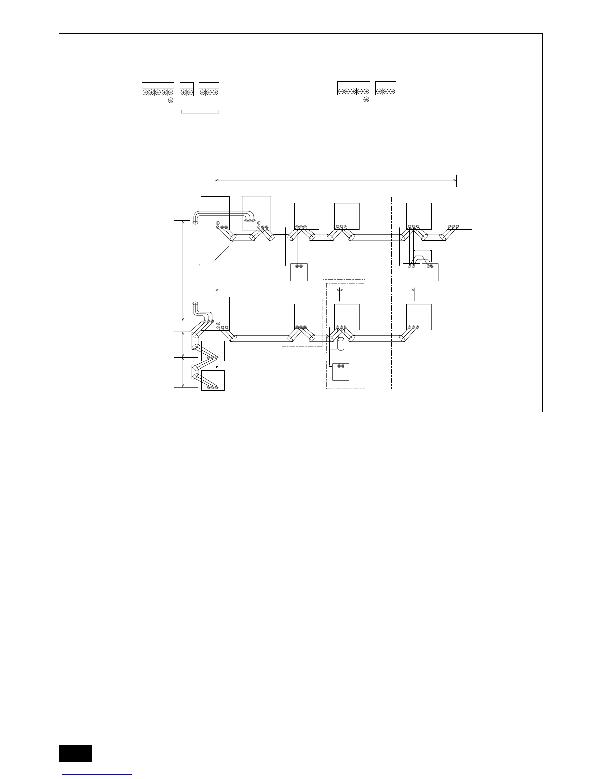
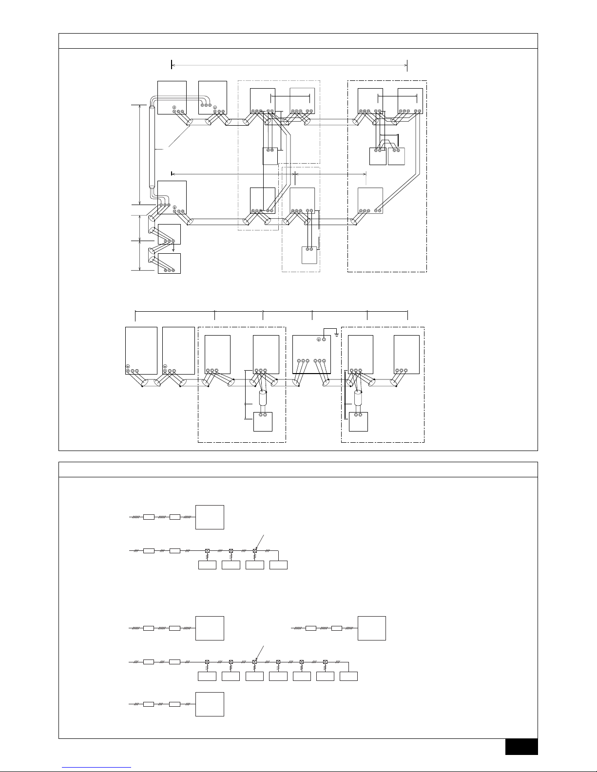
[Fig. 10.3.1]
M-NET Remote controller
A
B
C
E
D
M1 M2
TB3
IC
(52)
M1 M2 S
TB5
RC
(01)
IC
M1 M2 S
TB5
(03)
IC
M1 M2 S
TB5
(02)
IC
M1 M2 S
TB5
(04)
IC
M1 M2 S
TB5
(05)
IC
M1 M2 S
TB5
(07)
IC
M1 M2 S
TB5
(06)
L
2
L
1
(101)
RC
(105)
RC
(104)
RC
(155)
OS
M1 M2
M1 M2 S
TB7
TB3
(53)
OC
r
3
M1M2S
Power Supply
Unit
M1M2S
G50
L
3
L
6
L
7
L
4
L
5
r
2
r
4
r
1
AB AB AB
AB
M1 M2
M1 M2 S
TB7
TB3
(51)
OC
<PUHY-P-YEM-A>
<PUHN-P-YEM-A> <PUHY-P-YEM-A>
10.3
9
10.4
[Fig. 10.4.1]
10.3
[Fig. 10.3.2]
MA Remote controller
A
B
C
E
D
M1 M2
TB3
IC
(52)
M1 M2 1 2S
TB5 TB15
12
TB15
12
TB15
12
TB15
12
TB15
12
TB15
12
TB15
MA
(01)
IC
M1 M2 S
TB5
(03)
IC
M1 M2 S
TB5
(02)
IC
M1 M2 S
TB5
(04)
IC
M1 M2 S
TB5
(05)
IC
M1 M2 S
TB5
(07)
IC
M1 M2 S
TB5
(06)
L
2
L
1
MAMAMA
OS
M1 M2
M1 M2 S
TB7
TB3
(51)
OC
M1 M2
M1 M2 S
TB7
TB3
(53)
<PUHY-P-YEM-A>
OC
c
1
c
4
c
3
S
Power Supply
Unit
S
G50
L
3
L
6
L
7
L
4
c
3
ABABAB
M1M2
M1M2
c
1
c
1
c
2
c
2
AB
<PUHN-P-YEM-A> <PUHY-P-YEM-A>
A Group 1
B Group 4
C Group 5
D Shielded Wire
E Sub Remote
Controller
( ) Address
M1 M2
TB3
RC
N
1
N
2
IC
M1M2 S
TB5
IC
M1M2 S
TB5
RP
AB
ABAB
S
TB2
ABS
TB3
L
4
r
1
OS
M1 M2
TB3
OC
L
7
r
1
RC
IC
M1M2 S
TB5
IC
M1M2 S
TB5
L
6
L
5
L
3
L
2
L
1
[Fig. 10.3.3]
Transmission booster unit
BA
C
3N~380–415V
L
1, L2, L3, N, PE
BA
~220–240V
L, N, PE
F FGF F
BA
D
3N~380–415V
L
1
, L2, L3, N, PE
BA
Å
H
~220–240V
L, N, PE
BA
E
3N~380–415V
L
1
, L2, L3, N, PE
BA
~220–240V
L, N, PE
F F F F F F F
G
<PUHY-P400/500YEM-A>
<PUHY-P600/650/700/750YSEM-A>
A Switch (Breakers for wiring)
B Breakers for current leakage
C Outdoor unit
D Outdoor unit (Variable capacity unit)
E Outdoor unit (Constant capacity unit)
F Indoor unit
G Pull box
H Transmission booster
ÅÅ
ÅÅ
Å Note:
1. The transmission booster may be required according to the number
of indoor units connected.
2. For switch capacity, see the installation manual for transmission
booster.
Ground
10
GB
D
F
INL
E
PGRRUTR
Contents
1. Safety precautions
1.1. Before installation and electric work
s Before installing the unit, make sure you read all the “Safety
precautions”.
s The “Safety precautions” provide very important points re-
garding safety. Make sure you follow them.
Symbols used in the text
Warning:
Describes precautions that should be observed to prevent danger of injury
or death to the user.
Caution:
Describes precautions that should be observed to prevent damage to the
unit.
Symbols used in the illustrations
: Indicates an action that must be avoided.
: Indicates that important instructions must be followed.
: Indicates a part which must be grounded.
: Beware of electric shock. (This symbol is displayed on the main unit label.)
<Color: yellow>
Warning:
Carefully read the labels affixed to the main unit.
Warning:
• Ask the dealer or an authorized technician to install the air conditioner.
- Improper installation by the user may result in water leakage, electric shock,
or fire.
• Install the unit in a place that can withstand its weight.
- Inadequate strength may cause the unit to fall down, resulting in injuries.
• Use the specified cables for wiring. Make the connections securely so
that the outside force of the cable is not applied to the terminals.
- Inadequate connection and fastening may generate heat and cause a fire.
• Prepare for strong winds and earthquakes and install the unit at the specified place.
- Improper installation may cause the unit to topple over and result in injury.
• Always use an filter and other accessories specified by Mitsubishi Electric.
- Ask an authorized technician to install the accessories. Improper installation
by the user may result in water leakage, electric shock, or fire.
• Never repair the unit. If the air conditioner must be repaired, consult the
dealer.
- If the unit is repaired improperly, water leakage, electric shock, or fire may
result.
• Do not touch the heat exchanger fins.
- Improper handling may result in injury.
• If refrigerant gas leaks during installation work, ventilate the room.
- If the refrigerant gas comes into contact with a flame, poisonous gases will
be released.
• Install the air conditioner according to this Installation Manual.
- If the unit is installed improperly, water leakage, electric shock, or fire may
result.
• Have all electric work done by a licensed electrician according to “Electric Facility Engineering Standard” and “Interior Wire Regulations”and
the instructions given in this manual and always use a special circuit.
- If the power source capacity is inadequate or electric work is performed improperly, electric shock and fire may result.
• Securely install the outdoor unit terminal cover (panel).
- If the terminal cover (panel) is not installed properly, dust or water may enter
the outdoor unit and fire or electric shock may result.
• When installing and moving the air conditioner to another site, do not
charge it with a refrigerant different from the refrigerant (R407C) specified on the unit.
- If a different refrigerant or air is mixed with the original refrigerant, the refrig-
erant cycle may malfunction and the unit may be damaged.
• If the air conditioner is installed in a small room, measures must be taken
to prevent the refrigerant concentration from exceeding the safety limit
even if the refrigerant should leak.
- Consult the dealer regarding the appropriate measures to prevent the safety
limit from being exceeded. Should the refrigerant leak and cause the safety
limit to be exceeded, hazards due to lack of oxygen in the room could result.
• When moving and reinstalling the air conditioner, consult the dealer or
an authorized technician.
- If the air conditioner is installed improperly, water leakage, electric shock, or
fire may result.
• After completing installation work, make sure that refrigerant gas is not
leaking.
- If the refrigerant gas leaks and is exposed to a fan heater, stove, oven, or
other heat source, it may generate noxious gases.
• Do not reconstruct or change the settings of the protection devices.
- If the pressure switch, thermal switch, or other protection device is shorted
and operated forcibly, or parts other than those specified by Mitsubishi Electric are used, fire or explosion may result.
• To dispose of this product, consult your dealer.
• The installer and system specialist shall secure safety against leakage
according to local regulation or standards.
- Following standards may be applicable if local regulation are not available.
• Pay a special attention to the place, such as a basement, etc. where refrigeration gas can not disperse into the atmosphere, since refrigeration
is heavier than the air.
1.2. Precautions for devices that use R407C
refrigerant
Caution:
• Do not use the existing refrigerant piping.
- The old refrigerant and refrigerator oil in the existing piping contains a large
amount of chlorine which may cause the refrigerator oil of the new unit to
deteriorate.
• Use refrigerant piping made of phosphorus deoxidized copper and copper alloy seamless pipes and tubes. In addition, be sure that the inner
and outer surfaces of the pipes are clean and free of hazardous sulphur,
oxides, dust/dirt, shaving particles, oils, moisture, or any other contaminant.
- Contaminants on the inside of the refrigerant piping may cause the refriger-
ant residual oil to deteriorate.
• Store the piping to be used during installation indoors and keep both
ends of the piping sealed until just before brazing. (Store elbows and
other joints in a plastic bag.)
- If dust, dirt, or water enters the refrigerant cycle, deterioration of the oil and
compressor trouble may result.
• Use ester oil, ether oil or alkylbenzene (small amount) as the refrigerator
oil to coat flares and flange connections.
- The refrigerator oil will degrade if it is mixed with a large amount of mineral
oil.
1. Safety precautions .................................................................................... 10
1.1. Before installation and electric work ........................................ 10
1.2. Precautions for devices that use R407C refrigerant ................ 10
1.3. Before getting installed ............................................................ 11
1.4. Before getting installed (moved) - electrical work .................... 11
1.5. Before starting the test run ...................................................... 11
2. Specifications ............................................................................................ 11
3. Confirmation of parts attached ................................................................. 12
4. Combination with outdoor units ................................................................ 12
5. Space required around unit ...................................................................... 12
6. Lifting method ........................................................................................... 12
7. Installation of unit ...................................................................................... 13
7.1. Installation ............................................................................... 13
7.2. Connecting direction for refrigerant piping .............................. 13
8. Refrigerant piping installation ................................................................... 13
8.1. Caution .................................................................................... 13
8.2. Refrigerant piping system ........................................................ 13
9. Additional refrigerant charge ..................................................................... 14
9.1. Calculation of additional refrigerant charge ............................. 14
9.2. Caution for piping connection / valve operation....................... 15
9.3. Oil balance pipe connection method ....................................... 16
9.4. Distributor (gas) connection method ....................................... 17
9.5. How to install branch pipe ....................................................... 17
9.6 Airtight test, evacuation and refrigerant charging.................... 17
9.7 Thermal insulation of refrigerant piping ................................... 18
10. Wiring ....................................................................................................... 18
10.1. Caution .................................................................................... 18
10.2. Control box and connecting position of wiring ......................... 19
10.3. Wiring transmission cables ...................................................... 19
10.4. Wiring of main power supply and equipment capacity ............ 20
11. Test run ..................................................................................................... 21
11.1. The following phenomena do not represent trouble
(emergency) ............................................................................ 21
11
GB
D
F
INL
E
PGRRUTR
• Install the power cable so that tension is not applied to the cable.
- Tension may cause the cable to break and generate heat and cause a fire.
• Install a leak circuit breaker, as required.
- If a leak circuit breaker is not installed, electric shock may result.
• Use power line cables of sufficient current carrying capacity and rating.
- Cables that are too small may leak, generate heat, and cause a fire.
• Use only a circuit breaker and fuse of the specified capacity.
- A fuse or circuit breaker of a larger capacity, a steel or copper wire may result
in a general unit failure or fire.
• Do not wash the air conditioner units.
- Washing them may cause an electric shock.
• Be careful that the installation base is not damaged by long use.
- If the damage is left uncorrected, the unit may fall and cause personal injury
or property damage.
• Install the drain piping according to this Installation Manual to ensure
proper drainage. Wrap thermal insulation around the pipes to prevent
condensation.
- Improper drain piping may cause water leakage causing damage to furniture
and other possessions.
• Be very careful about product transportation.
- One person should not carry the product as it weighs more than 20 kg.
- Some products use PP bands for packaging. Do not use any PP bands as a
means of transportation. It is dangerous.
- Do not touch the heat exchanger fins. Doing so may cut your fingers.
- When transporting the outdoor unit, support it at the specified positions on
the unit base. Also support the outdoor unit at four points so that it cannot
slip sideways.
• Safely dispose of the packing materials.
- Packing materials, such as nails and other metal or wooden parts, may cause
stabs or other injuries.
- Tear apart and throw away plastic packaging bags so that children will not
play with them. If children play with a plastic bag which was not torn apart,
they face the risk of suffocation.
1.5. Before starting the test run
Caution:
• Turn on the power at least 12 hours before starting operation.
- Starting operation immediately after turning on the main power switch can
result irreversible damage to internal parts. Keep the power switch turned on
during the operational season.
• Do not touch the switches with wet fingers.
- Touching a switch with wet fingers can cause electric shock.
• Do not touch the refrigerant pipes during and immediately after operation.
- During and immediately after operation, the refrigerant pipes may be hot and
may be cold, depending on the condition of the refrigerant flowing through
the refrigerant piping, compressor, and other refrigerant cycle parts. Your
hands may suffer burns or frostbite if you touch the refrigerant pipes.
• Do not operate the air conditioner with the panels and guards removed.
- Rotating, hot, or high-voltage parts can cause injuries.
• Do not turn off the power immediately after stopping operation.
- Always wait at least five minutes before turning off the power. Otherwise,
water leakage and trouble may occur.
• Do not touch the surface of the compressor during servicing.
- If unit is connected to the supply and not running, crank case heater at com-
pressor base is operating.
• Use liquid refrigerant to fill the system.
- If gas refrigerant is used to seal the system, the composition of the refrigerant in the cylinder will change and performance may drop.
• Do not use a refrigerant other than R407C.
- If another refrigerant (R22, etc.) is used, the chlorine in the refrigerant may
cause the refrigerator oil to deteriorate.
• Use a vacuum pump with a reverse flow check valve.
- The vacuum pump oil may flow back into the refrigerant cycle and cause the
refrigerator oil to deteriorate.
• Do not use the following tools that are used with conventional refrigerants.
(Gauge manifold, charge hose, gas leak detector, reverse flow check valve,
refrigerant charge base, refrigerant recovery equipment)
- If the conventional refrigerant and refrigerator oil are mixed in the R407C,
the refrigerant may deteriorated.
- If water is mixed in the R407C, the refrigerator oil may deteriorate.
- Since R407C does not contain any chlorine, gas leak detectors for conven-
tional refrigerants will not react to it.
• Do not use a charging cylinder.
- Using a charging cylinder may cause the refrigerant to deteriorate.
• Be especially careful when managing the tools.
- If dust, dirt, or water gets in the refrigerant cycle, the refrigerant may deterio-
rate.
1.3. Before getting installed
Caution:
• Do not install the unit where combustible gas may leak.
- If the gas leaks and accumulates around the unit, an explosion may result.
• Do not use the air conditioner where food, pets, plants, precision instruments, or artwork are kept.
- The quality of the food, etc. may deteriorate.
• Do not use the air conditioner in special environments.
- Oil, steam, sulfuric smoke, etc. can significantly reduce the performance of
the air conditioner or damage its parts.
• When installing the unit in a hospital, communication station, or similar
place, provide sufficient protection against noise.
- The inverter equipment, private power generator, high-frequency medical
equipment, or radio communication equipment may cause the air conditioner
to operate erroneously, or fail to operate. On the other hand, the air conditioner may affect such equipment by creating noise that disturbs medical
treatment or image broadcasting.
• Do not install the unit on a structure that may cause leakage.
- When the room humidity exceeds 80 % or when the drain pipe is clogged,
condensation may drip from the indoor unit. Perform collective drainage work
together with the outdoor unit, as required.
1.4. Before getting installed (moved) - elec-
trical work
Caution:
• Ground the unit.
- Do not connect the ground wire to gas or water pipes, lightning rods, or
telephone ground lines. Improper grounding may result in electric shock.
• The reverse phase of L lines (L
1, L2, L3) can detected (Error cord: 4103),
but the reverse phase of L lines and N line can not be detected.
- Some electric parts may be damaged when power is supplied under the
miss wiring.
2. Specifications
Model
Noise level (50 / 60 Hz)
Net weight
Allowable pressure
External static pressure
Refrigerant
Indoor units
Total capacity
Model / Quantity
Operation temperature
PUHY-P400YEM-A PUHY-P500YEM-A
60 / 61 dB <A>
440 kg 475 kg
HP: 2.94 MPa, LP: 1.6 MPa
0 MPa
R407C: 16 kg R407C: 21 kg
50 ~ 130 %
25 ~ 250 / 1 ~ 20 25 ~ 250 / 1 ~ 20
Cooling mode: – 5 °CDB ~ 43 °CDB (10 °CDB ~ 43 °CDB with outdoor unit at lower position, or with indoor unit
25 type only is working.)
Heating mode: – 12 °CWB ~ 15.5 °CWB (– 12 °CWB ~ 10 °CWB with indoor unit 25 type only is working.)
12
GB
D
F
INL
E
PGRRUTR
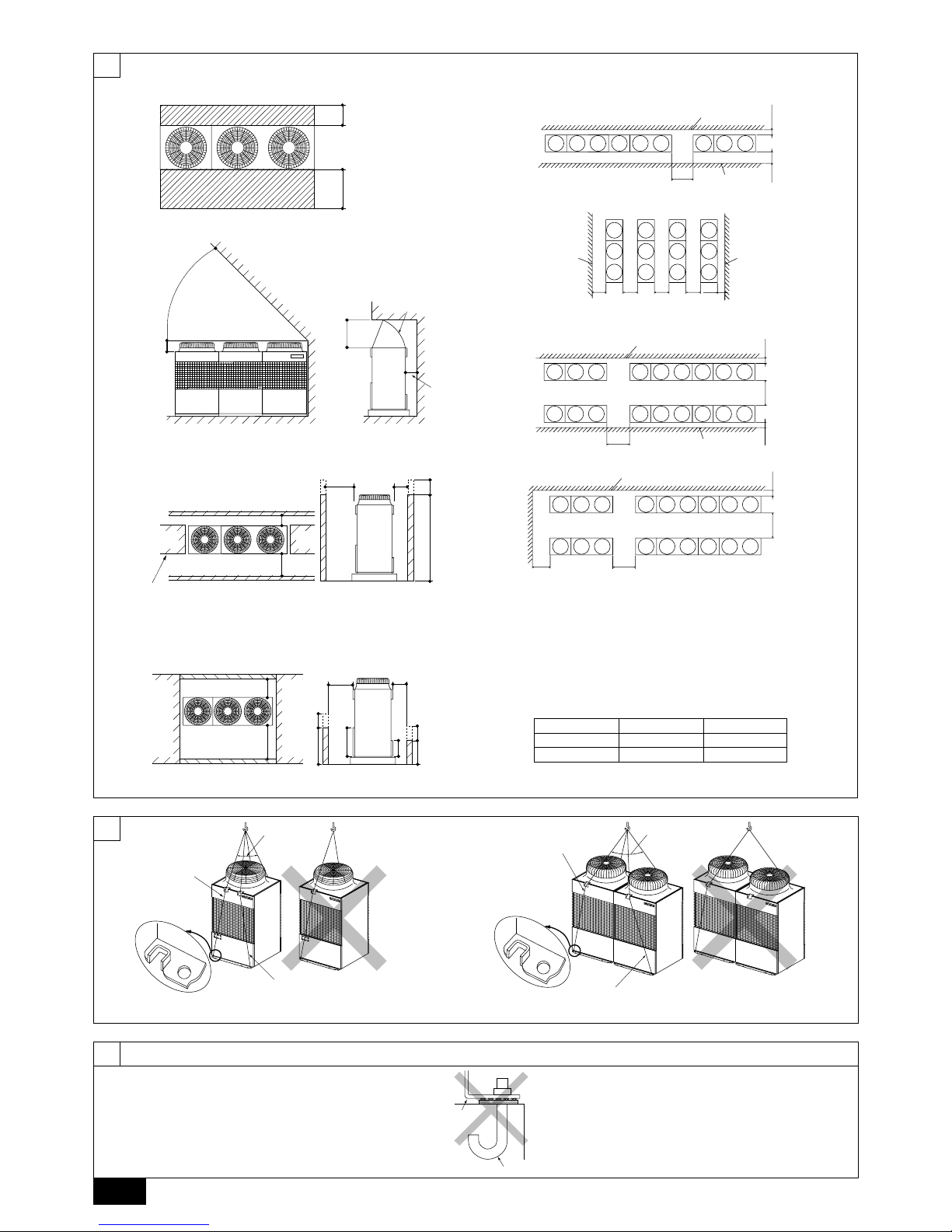
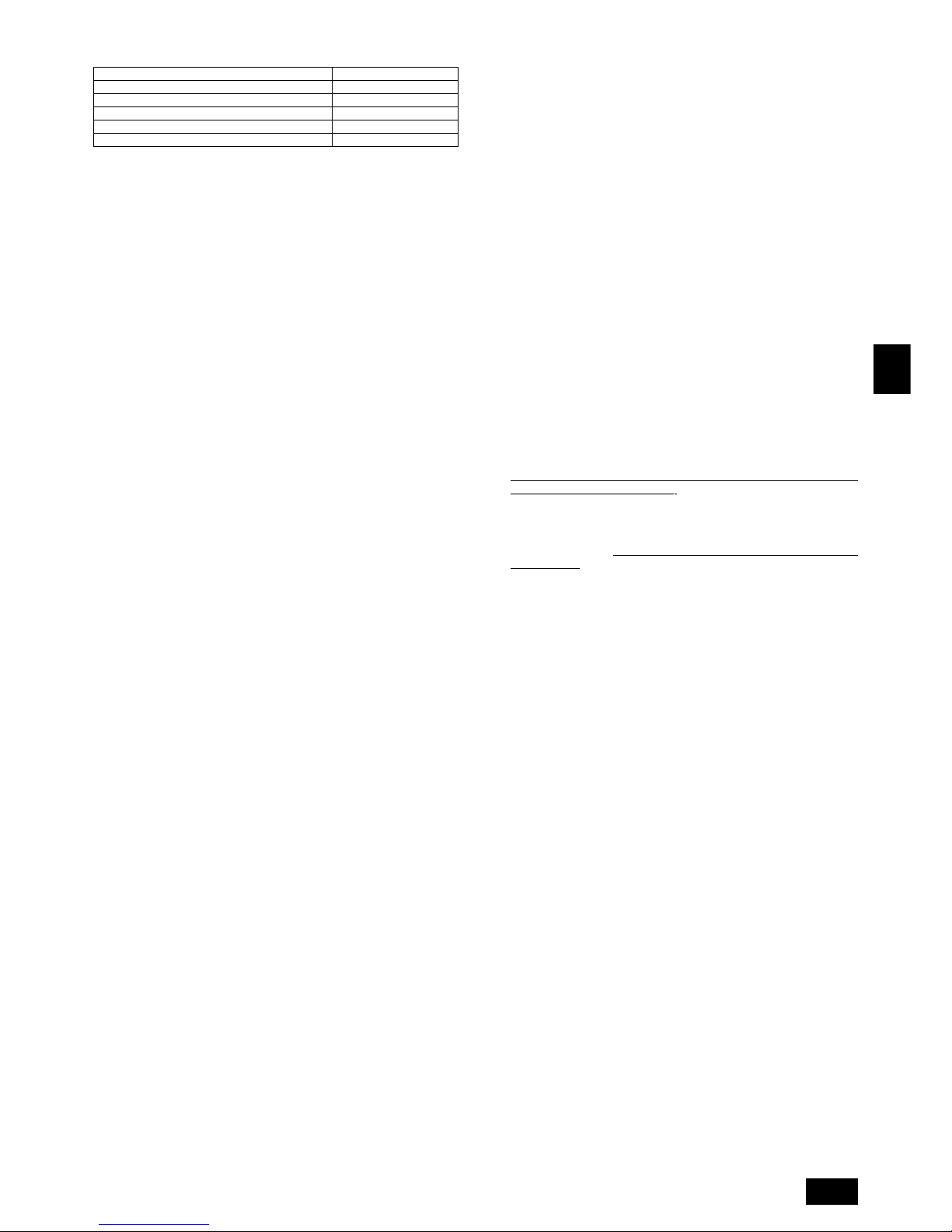
6. Lifting method
[Fig. 6.0.1] (P.2)
Caution:
Be very careful when carrying the product.
- Do not have only one person to carry product if it weighs more than 20 kg.
- PP bands are used to pack some products. Do not use them as a mean for transportation because they are dangerous.
- Do not touch heat exchanger fins with your bare hands. Otherwise you cut your hands.
- Tear plastic packaging bag and scrap it so that children cannot play with it. Otherwise plastic packaging bag may suffocate children.
- When carrying outdoor unit, be sure to support it at four points. Carrying with 3-point support may make outdoor unit unstable, resulting in it falling.
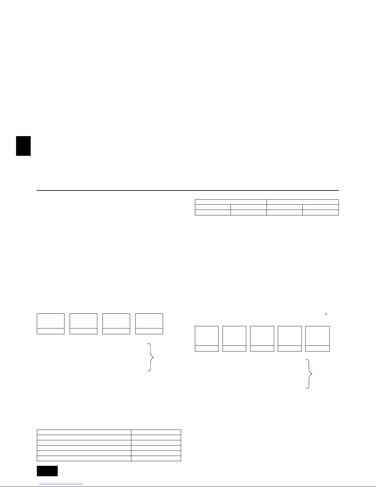
5. Space required around unit
[Fig. 5.0.1] (P.2)
<A> Top view <B> Side view
<C> When there is little space up to an obstruction
A Front
B No restrictions on wall height (left and right)
C Air outlet guide (Procured at the site)
D Must be open E Wall height (H)
L1 L2
PUHN-P-YEM-A 450 250
PUHY-P-YEM-A 450 450
(1) Basic space required
A space of at least 250 mm is necessary at the back for inlet air. Taking servicing,
etc. from the rear into account, a space of about 450 mm should be provided, the
same as at the front.
(2) When there is an obstruction above the unit
(3) When inlet air enters from right and left sides of unit
• Wall heights (H) of the front and the back sides shall be within overall height of
unit.
• When the total height is exceeded, add the “h” dimension of the Fig. 5.0.1 to L
1
and L2.
(4) When unit is surrounded by walls
Note:
• Wall heights (H) of the front and the back sides shall be within overall
height of unit.
• If the panel height is exceeded, add the “h” dimension of the Fig. 5.0.1 to
L1 and L2.
L
1 L2
PUHN-P-YEM-A 450 250
PUHY-P-YEM-A 450 450
Example: When h is 100,
the L1 dimension becomes 450 + 100 = 550 mm.
(5) Collective installation and continuous installation
• Space required for collective installation and continuous installation:
When installing several units, leave the space between each block considering
passage for air and people.
• Open in the two directions.
• In case wall height (H) exceeds overall height of unit, add “h” dimension (h =
wall height <H> – overall height of unit) to * marked dimension.
• If there is a wall at both the front and the rear of the unit, install up to three units
consecutively in the side direction and provide a space of 1000 mm or more as
inlet space/passage space for each three units.
Super Y
Model
Noise level (50 / 60 Hz)
Net weight
Constant capacity unit
Variable capacity unit
Allowable pressure
External static pressure
Constant capacity unit
Refrigerant
Variable capacity unit
Indoor units
Total capacity
Model / Quantity
Operation temperature
PUHY-P600YSEM-A PUHY-P650YSEM-A PUHY-P700YSEM-A PUHY-P750YSEM-A
61.5 / 62.0 dB <A> 62.0 / 62.5 dB <A> 61.5 / 62.0 dB <A> 62.0 / 62.5 dB <A>
248 kg 263 kg 248 kg 263 kg
440 kg 440 kg 475 kg 475 kg
HP: 2.94 MPa, LP: 1.6 MPa
0 MPa
R407C: 6.5 kg R407C: 8.5 kg R407C: 6.5 kg R407C: 8.5 kg
R407C: 16 kg R407C: 16 kg R407C: 21 kg R407C: 21 kg
50 ~ 130 %
20 ~ 250 / 2 ~ 32
Cooling mode: – 5 °CDB ~ 43 °CDB (10 °CDB ~ 43 °CDB with outdoor unit at lower position, or with indoor unit
20 or 25 type only is working.)
Heating mode: – 15 °CWB ~ 15.5 °CWB (– 12 °CWB ~ 10 °CWB with indoor unit 20 or 25 type only is working.)
3. Confirmation of parts attached
PUHY-P400/500YEM-A
1 Conduit mounting plate (ø62) × 1 2 Conduit mounting plate (ø53) × 1 3 Conduit mounting plate (ø46) × 1
4 Tapping screw M4 × 4 5 Connecting pipe × 1 (Connecting pipe is fixed with the unit)
6 Packing (inside ø29, outside ø39) × 1 7 Wire mounting plate × 1
PUHN-P200/250YEM-A
1 Conduit mounting plate (ø40) × 1 2 Conduit mounting plate (ø33) × 1 3 Conduit mounting plate (ø27) × 1
4 Tapping screw M4 × 4 5 Oil balance pipe 1 × 1 6 Connecting pipe × 1 (Connecting pipe is fixed with the unit)
7 Packing (inside ø23, outside ø35) × 1 8 Seal × 2 9 Distributor kit × 1
4. Combination with outdoor units
A Super Y (PUHY-P600/650/700/750YSEM-A) is produced when a Constant Capacity Unit (PUHN-P200/250YEM-A) is combined with this unit (PUHY-P400/
500YEM-A).
Use attachment parts
99
99
9 (Distributor kit) in constant capacity unit (PUHN-
P200/250YEM-A) when making a combination of these units.
For R407 models
Super Y Variable capacity unit Constant capacity unit
PUHY-P600YSEM-A PUHN-P200YEM-A
PUHY-P650YSEM-A
PUHY-P400YEM-A
PUHN-P250YEM-A
PUHY-P700YSEM-A PUHN-P200YEM-A
PUHY-P750YSEM-A
PUHY-P500YEM-A
PUHN-P250YEM-A
13
GB
D
F
INL
E
PGRRUTR
7. Installation of unit
7.1. Installation
[Fig. 7.1.1] (P.2)
A M10 anchor bolt procured at the site. B Corner is not seated.
• Fix unit tightly with bolts so that unit will not fall down due to earthquake or gust
of wind.
• Use concrete or angle bracket for foundation of unit.
• Vibration may be transmitted to the installation section and noise and vibration
may be generated from the floor and walls, depending on the installation conditions. Therefore, provide ample vibrationproofing (cushion pads, cushion
frame, etc.).
• Be sure that the corners are firmly seated. If the corners are not firmly seated,
the installation feet may be bent.
Warning:
• Be sure to install unit in a place strong enough to withstand its weight.
Any lack of strength may cause unit to fall down, resulting in a personal
injury.
• Have installation work in order to protect against a strong wind and earthquake.
Any installation deficiency may cause unit to fall down, resulting in a
personal injury.
When building the foundation, give full attention to the floor strength, drain water
disposal <during operation, drain water flows out of the unit>, and piping and wiring routes.
Down piping and down wiring precautions
When down piping and down wiring are performed, be sure that foundation and
base work does not block the base through holes. When down piping is performed,
make the foundation at least 150 mm high so that the piping can pass under the
bottom of the unit.
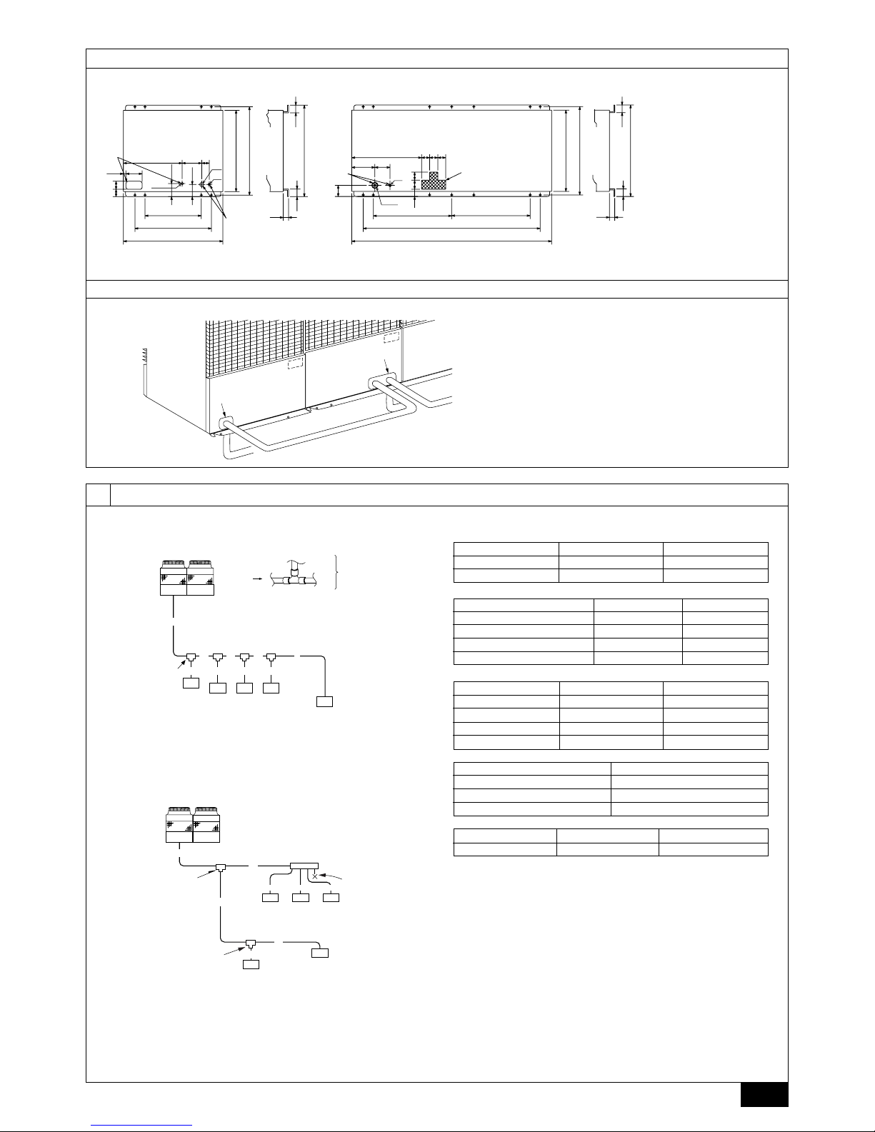
[Fig. 7.1.2] (P.3)
A Bottom piping through hole B (bolt hole)
C (bolt hole for old models) D Bottom wiring through hole
7.2. Connecting direction for refrigerant piping
[Fig. 7.2.1] (P.3)
A Knock-out hole B Bottom piping
C Front piping
D Connect piping (to constant capacity unit) (In the case of Super-Y)
8. Refrigerant piping installation
Connecting the piping is a terminal-branch type in which refrigerant piping from
the outdoor unit is branched at the terminal and connected to each of the indoor
units.
The method of connection consists of flare connections at the indoor units, flange
connections for the piping of the outdoor unit and flare connections for the liquid
piping. Note that the branched sections are brazed.
Warning:
Always use extreme care to prevent the refrigerant gas (R407C) from leaking
while using fire or flame. If the refrigerant gas comes in contact with the
flame from any source, such as a gas stove, it breaks down and generates a
poisonous gas which can cause gas poisoning. Never weld in an unventilated
room. Always conduct an inspection for gas leakage after installation of the
refrigerant piping has been completed.
8.1. Caution
1 Use the following materials for refrigeration piping.
• Material: Use refrigerant piping made of phosphorus deoxidized copper.
In addition, be sure that the inner and outer surfaces of the pipes are clean
and free of hazardous sulphur, oxides, dust/dirt, shaving particles, oils,
moisture, or any other contaminant. (For R407C models)
2 Commercially available piping often contains dust and other materials. Always
blow it clean with a dry inert gas.
3 Use care to prevent dust, water or other contaminants from entering the piping
during installation.
4 Reduce the number of bending portions as much as possible, and make bend-
ing radius as big as possible.
5 Always observe the restrictions on the refrigerant piping (such as rated length,
the difference between high/low pressures, and piping diameter). Failure to do
so can result in equipment failure or a decline in heating/cooling performance.
6 The City Multi Y Series will stop due to an abnormality due to excessive or
insufficient coolant. At such a time, always properly charge the unit. When
servicing, always check the notes concerning pipe length and amount of additional refrigerant at both locations, the refrigerant volume calculation table on
the back of the service panel and the additional refrigerant section on the labels for the combined number of indoor units.
7 Use liquid refrigerant to fill the system.
8 Never use refrigerant to perform an air purge. Always evacuate using a vacuum
pump.
9 Always insulate the piping properly. Insufficient insulation will result in a de-
cline in heating/cooling performance, water drops from condensation and other
such problems.
0 When connecting the refrigerant piping, make sure the ball valve of the out-
door unit is completely closed (the factory setting) and do not operate it until
the refrigerant piping for the outdoor and indoor units has been connected, a
refrigerant leakage test has been performed and the evacuation process has
been completed.
A Always use a non-oxidizing brazing material for brazing the parts. If a non-
oxidizing brazing material is not used, it could cause clogging or damage to
the compressor unit.
B Never perform outdoor unit piping connection work when it is raining.
Warning:
When installing and moving the unit, do not charge it with refrigerant other
than the refrigerant specified on the unit.
- Mixing of a different refrigerant, air, etc. may cause the refrigerant cycle to malfunction and result in severe damage.
Caution:
• Use a vacuum pump with a reverse flow check valve. (For R407C models)
- If the vacuum pump does not have a reverse flow check valve, the vacuum
pump oil may flow back into the refrigerant cycle and cause deterioration of
the refrigerator oil and other trouble.
• Do not use the tools shown below used with conventional refrigerant.
(For R407C models)
(Gauge manifold, charge hose, gas leak detector, check valve, refrigerant
charge base, vacuum gauge, refrigerant recovery equipment)
- Mixing of conventional refrigerant and refrigerator oil may cause the refrig-
erator oil to deteriorate.
- Mixing of water will cause the refrigerator oil to deteriorate.
- R407C refrigerant does not contain any chlorine. Therefore, gas leak detec-
tors for conventional refrigerants will not react to it.
• Manage the tools more carefully than normal. (For R407C models)
- If dust, dirt, or water gets in the refrigerant cycle, the refrigerator oil will dete-
riorate.
• Never use existing refrigerant piping. (For R407C models)
- The large amount of chlorine in conventional refrigerant and refrigerator oil
in the existing piping will cause the new refrigerant to deteriorate.
• Store the piping to be used during installation indoors and keep both
ends of the piping sealed until just before brazing.
- If dust, dirt, or water gets into the refrigerant cycle, the oil will deteriorate and
the compressor may fail.
• Do not use a charging cylinder. (For R407C models)
- Using a charging cylinder may cause the refrigerant to deteriorate.
• Do not use special detergents for washing piping.
8.2. Refrigerant piping system
Å Liquid line ı Gas line
Ç Total capacity of indoor units Î Model number
‰ Downstream unit model total Ï Branch kit model
Ì 4 branching header Ó 7 branching header
¬ 10 branching header
Connection Example (PUHY-P400/500YEM-A)
[Fig.8.2.1] (P.3)
A Outdoor unit
B First branch
The first branch on the outdoor unit must be the CMY-Y202-F.
C Indoor unit D To downstream units
Note:
• The model total for downstream units shown in the table below is the
model total when viewed from Point A in the drawing above.
14
GB
D
F
INL
E
PGRRUTR
Liquid pipe
size total
length of
ø15.88 × 0.25
(m) × 0.25 (kg/m)
Liquid pipe
size total
length of
ø12.7 × 0.12
(m) × 0.12 (kg/m)
Liquid pipe
size total
length of
ø9.52 × 0.06
(m) × 0.06 (kg/m)
Liquid pipe
size total
length of
ø6.35
×
0.024
(m) × 0.024 (kg/m)
Liquid pipe
size total
length of
ø19.05 × 0.29
(m) × 0.29 (kg/m)
At the
conditions
below:
9. Additional refrigerant charge
9.1. Calculation of additional refrigerant
charge
[PUHY-P400/500YEM-A]
• Additional refrigerant charge
At the time of shipping, the outdoor unit PUHY-P400 is charged with 16 kg of
refrigerant and the PUHY-P500 is charged with 21 kg. As this charge does not
include the amount needed for extended piping, additional charging for each refrigerant line will be required on site. In order that future servicing may be properly
provided, always keep a record of the size and length of each refrigerant line and
the amount of additional charge by writing it in the space provided on the outdoor
unit.
• Calculation of additional refrigerant charge
• Calculate the amount of additional charge based on the length of the piping
extension and the size of the refrigerant line.
• Use the table to the right as guide to calculating the amount of additional
charging and charge the system according.
• If the calculation results in a fraction of less than 0.1 kg, round up to the next
0.1 kg. For example, if the result of the calculation was 15.02 kg, round the
result up to 15.1 kg.
<Additional charge>
++ + +
α
<Example>
Indoor 1: 125 A: ø15.88 30 m a: ø9.52 10 m
2: 100 B: ø12.7 10 m b: ø9.52 20 m
3: 40 C: ø12.7 15 m c: ø6.35 10 m
4: 32 d: ø6.35 10 m
5: 32 e: ø6.35 10 m
The total length of each liquid line is as follows:
ø15.88: A = 30 m
ø12.7: B + C = 10 + 15 = 25 m
ø9.52: a + b = 10 + 20 = 30 m
ø6.35: c + d + e = 10 + 10 + 10 = 30 m
Therefore,
<Calculation example>
Additional
refrigerant charge = 30 × 0.25 + 25 × 0.12 + 30 × 0.06 + 30 × 0.024 + 2.0 = 15.1 kg
Value of α
Total capacity of connecting indoor units α
to Model 80 1.0 kg
Models 81 to 160 1.5 kg
Models 161 to 330 2.0 kg
Models 331 to 480 2.5 kg
Models 481 or more 3.0 kg
[Fig.8.2.2] (P.3)
A Outdoor unit
B First branch (Branch joint)
The first branch must be the CMY-Y202-F when the outdoor unit and header
branch are to be used.
C Branch joint D Indoor unit
E Branch header F Cap
Note:
• Branch piping cannot be used again after the header branch.
• The model total for downstream units shown in the table below is the
model total when viewed from Point A in the drawing above.
Connection Example (PUHY-P600/650/700/750YSEM-A)
[Fig.8.2.3] (P.4)
A Constant capacity unit B Variable capacity unit
C First branch D Indoor unit
E To downstream units
F Distributor (liquid), Distributor (gas) → Note2
G Oil balance pjpe 1 (accessory) (for distribution within the unit)
H Distributor (gas) (accessory) I Distributor (liquid) (accessory)
J Gas line A K Liquid line A
L Gas line B M Liquid line B
N Gas line (main) C O Liquid line (main) C
P Indicates piping connection points
Note 1:
• The model total for downstream units shown in the table below is the
model total when viewed from Point A in the drawing above.
• With the exception of PUHY-P600YSEM-A, the first branch is always CMYY302-F.
Note2:
• Because it is built into the variable capacity unit, B is used to carry liquid
only. Set the constant capacity unit and variable capacity unit in accordance with the G dimension given in the figure above (G=0.01 m).
Note3:
• Distributor kit is attached with constant capacity unit.
[Fig.8.2.4] (P.4)
A Constant capacity unit B Variable capacity unit
C First branch (Branch joint) D Branch joint
E Indoor unit F Branch header
G cap
H Distributor (liquid), Distributor (gas) → Note2
Note 1:
• The model total for downstream units shown in the table below is the
model total when viewed from Point A in the drawing above.
• With the exception of PUHY-P600YSEM-A, the first branch is always CMYY302-F.
Note2:
• Because it is built into the variable capacity unit, B is used to carry liquid
only. Set the constant capacity unit and variable capacity unit in accordance with the G dimension given in the figure above (G=0.01m).
Note3:
• Distributor kit is attached with constant capacity unit.
[PUHY-P600/650/700/750YSEM-A] (kg)
Variable capacity unit Constant capacity unit
P400 P500 P200 P250
16 21 6.5 8.5
• Additional refrigerant charge
The outdoor unit is charged with refrigerant at the time of shipping according to the
chart above. As this charge does not include the amount needed for extended
piping, additional charging for each refrigerant line will be required on site. In order
that future servicing may be properly provided, always keep a record of the size
and length of each refrigerant line and the amount of additional charge by writing it
in the space provided on the outdoor unit.
• Calculation of additional refrigerant charge
• Calculate the amount of additional charge based on the length of the piping
extension and the size of the refrigerant line.
• Use the table to the right as guide to calculating the amount of additional
charging and charge the system according.
• If the calculation results in a fraction of less than 0.1 kg, round up to the next
0.1 kg. For example, if the result of the calculation was 20.03 kg, round the
result up to 20.1 kg.
• If the total amount of refrigerant including the amount of refrigerant sealed in
the outdoor unit when shipped from the factor plus additional refrigerant for
extension piping exceeds 73 kg, use 73 kg as the total amount of refrigerant.
Amount of refrigerant when shipped from factory + added refrigerant
=
73 kg.
<Additional charge>
++ ++ +
α
<Example>
Indoor 1: 125 A: ø12.7 3 m a: ø9.52 10 m
2: 125 B: ø15.88 1 m b: ø9.52 5 m
3: 125 C: ø19.05 30 m c: ø9.52 5 m
4: 125 D: ø15.88 10 m d: ø9.52 10 m
5: 100 E: ø12.7 5 m e: ø9.52 15 m
6: 40 F: ø12.7 15 m f: ø6.35 5 m
The total length of each liquid line is as follows:
ø19.05: C = 30 m
ø15.88: B + D = 1 + 10 = 11 m
ø12.7: A + E + F = 3 + 5 + 15 = 23 m
ø9.52: a + b + c + d + e = 10 + 5 + 5 + 10 + 15 = 45 m
ø6.35: f = 5 m
Therefore,
<Calculation example>
Additional
refrigerant charge = 30 × 0.29 + 11 × 0.25 + 23 × 0.12 +
45 × 0.06 + 5 × 0.024 + 3.0 = 20.1 kg
At the
conditions
below:
Liquid pipe size
total length of
ø15.88 × 0.25
(m) × 0.25 (kg/m)
Liquid pipe size
total length of
ø12.7 × 0.12
(m) × 0.12 (kg/m)
Liquid pipe size
total length of
ø9.52 × 0.06
(m) × 0.06 (kg/m)
Liquid pipe size
total length of
ø6.35 × 0.024
(m) × 0.024 (kg/m)
15
GB
D
F
INL
E
PGRRUTR
Value of α
Total capacity of connecting indoor units α
to Model 80 1.0 kg
Models 81 to 160 1.5 kg
Models 161 to 330 2.0 kg
Models 331 to 480 2.5 kg
Models 481 or more 3.0 kg
9.2. Caution for piping connection / valve
operation
[PUHY-P400/500YEM-A]
• Conduct piping connection and valve operation accurately.
• The gas side connecting pipe is assembled in factory before shipment.
1 For brazing to the connecting pipe with flange, remove the connecting pipe
with flange from the ball valve, and braze it outside of the unit.
2 During the time when removing the connecting pipe with flange, remove
the seal attached on the rear side of this sheet and paste it onto the flange
surface of the ball valve to prevent the entry of dust into the valve.
3 The refrigerant circuit is closed with a round, close-packed packing at the
shipment to prevent gas leak between flanges. As no operation can be
done under this state, be sure to replace the packing with the hollow packing attached at the piping connection.
4 At the mounting of the hollow packing, wipe off dust attached on the flange
sheet surface and the packing. Coat refrigerating machine oil (R407C: Ester
oil, ether oil or alkylbenzene [small amount]) onto both surfaces of the
packing.
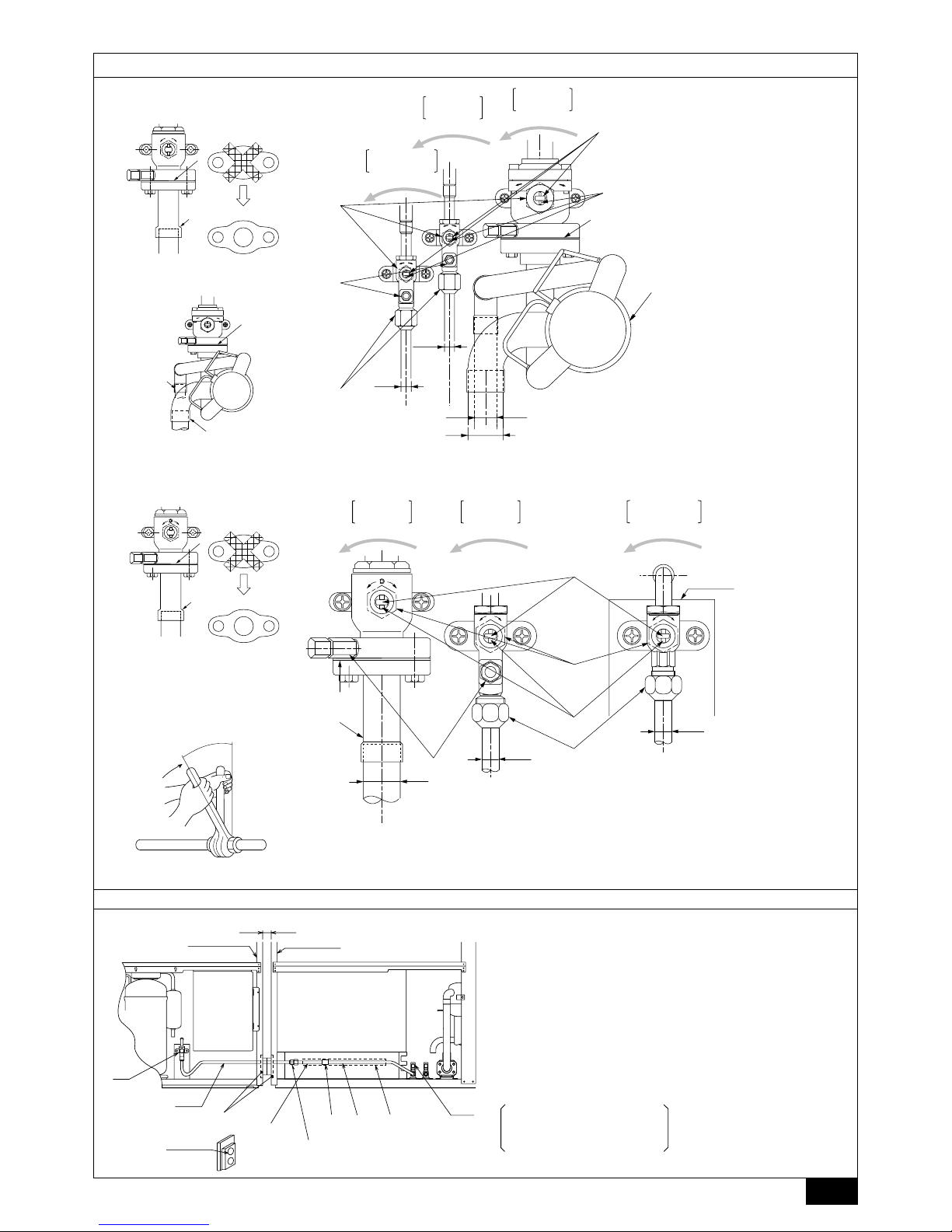
[Fig. 9.2.1] (P.4)
A Close-packed packing B Hollow packing
• After evacuation and refrigerant charge, ensure that the handle is fully open. If
operating with the valve closed, abnormal pressure will be imparted to the
high- or low-pressure side of the refrigerant circuit, giving damage to the compressor, four-way valve, etc.
• Determine the amount of additional refrigerant charge by using the formula,
and charge refrigerant additionally through the service port after completing
piping connection work.
• After completing work, tighten the service port and cap securely not to gener-
ate gas leak.
[Fig. 9.2.2] (P.4)
<A> [Ball valve (liquid side)]
<B> [Ball valve (gas side)]
<C> (This figure shows the valve in the fully open state.)
A Valve stem
[Fully closed at the factory, when connecting the piping, when evacuating,
and when charging additional refrigerant. Open fully after the operations
above are completed.]
B Stopper pin [Prevents the valve stem from turning 90° or more.]
C Packing (accessory)
D Connecting pipe (accessory)
[Use packing and securely install this pipe to the valve flange so that gas
leakage will not occur. (Tightening torque: 43 N·m (430 kg-cm)) Coat both
surfaces of the packing with refrigerating machine oil. (R407C: Ester oil,
ether oil or alkylbenzene [small amount])]
E Open (Operate slowly)
F Cap, copper packing
[Remove the cap and operate the valve stem. Always reinstall the cap after
operation is completed. (Valve stem cap tightening torque: 25 N·m
(250 kg-cm) or more)]
G Service port
[Use this port to evacuate the refrigerant piping and add an additional charge
at the site.
Open and close the port using a double-ended wrench.
Always reinstall the cap after operation is completed. (Service port cap
tightening torque: 14 N·m (140 kg-cm) or more)]
H Flare nut
[Tightening torque: 80 N·m (800 kg-cm)
Loosen and tighten this nut using a double-ended wrench.
Coat the flare contact surface with refrigerating machine oil (R407C: Ester
oil, ether oil or alkylbenzene [small amount])]
I ø15.88
J ø34.93
K Field piping
[Braze to the connecting pipe. (When brazing, use unoxidized brazing.)]
[PUHY-P600/650/700/750YSEM-A]
<For variable capacity unit>
• Conduct piping connection and valve operation accurately.
• After performing the following distributor (gas) connection, remove the con-
necting pipe included with the gas ball valve of the variable capacity unit, and
mount the distributor (gas) (accessory).
1 When brazing the distributor (gas), braze it outside of the unit before mount-
ing on the variable capacity unit.
2 During the time when removing the connecting pipe with flange, remove
the seal attached on the rear side of this sheet and paste it onto the flange
surface of the ball valve to prevent the entry of dust into the valve.
3 The refrigerant circuit is closed with a round, close-packed packing at ship-
ment to prevent gas leak between flanges. As no operation can be done
under this state, be sure to replace the packing with the hollow packing
attached at the piping connection.
4 At the mounting of the hollow packing, wipe off dust attached on the flange
sheet surface and the packing. Coat refrigerating machine oil (R407C: Ester
oil, ether oil or alkylbenzene [small amount])] onto both surfaces of the
packing.
[Fig. 9.2.3] (P.5)
<A> [When shipped from the manufacturer]
<B> [After installation]
A Close-packed packing B Hollow packing
• After evacuation and refrigerant charge, ensure that the handle is fully open. If
operating with the valve closed, abnormal pressure will be imparted to the
high- or low-pressure side of the refrigerant circuit, or a shortage of oil in the
compressor may occur due to lack of oil flow between units, giving damage to
the compressor, four-way valve, etc.
•
For evacuating, be sure to provide an oil balance pipe between the variable
capacity and constant capacity units.
• Determine the amount of additional refrigerant charge by using the formula,
and charge refrigerant additionally through the service port after completing
piping connection work.
• After completing work, shut the service port and cap tightly so that gas leaking
does not occur.
• Connect ball valve piping in the order of (oil balance) → (liquid side) → (gas
side).
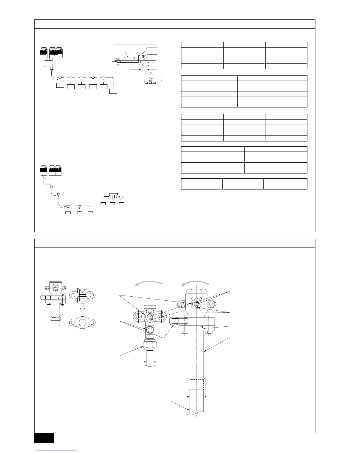
[Fig. 9.2.4] (P.5)
<A> [Ball valve (liquid side)]
<B> [Ball valve (gas side)]
<C> [Ball valve (oil balance side)]
<D> (This figure shows the valve in the fully open state.)
A Valve stem
[Fully closed at the factory, when connecting the piping, when evacuating, and
when charging additional refrigerant. Open fully after the operations above are
completed.]
B Stopper pin [Prevents the valve stem from turning 90° or more.]
C Packing (accessory)
D Distributor (Gas) (accessory)
[Mount packing (accessory) securely to the valve flange so that gas does not
leak. (Screw tightening torque: 43 N·m (430 kg·cm).) Apply a coat of refrigerating machine oil (R407C: Ester oil, ether oil or alkylbenzene [small amount]) to
both surfaces of the packing.]
E Open (Operate slowly)
F Cap, copper packing
[Remove the cap and operate the valve stem. Always reinstall the cap after
operation is completed. (Valve stem cap tightening torque: 25 N·m (250 kg·cm)
or more)]
G Service port
[Use this port to evacuate the refrigerant piping and add an additional charge
at the site.
Open and close the port using a double-ended wrench.
Always reinstall the cap after operation is completed. (Service port cap tightening torque: 14 N·m (140 kg·cm) or more)]
H Flare nut
[Tightening torque: 80 N·m (800 kg·cm) ··· liquid, 55 N·m (550 kg·cm) ··· oil
blance
Loosen and tighten this nut using a double-ended wrench.
Coat the flare contact surface with refrigerating machine oil (R407C: Ester oil,
ether oil or alkylbenzene [small amount])]
I ø34.93 (PUHY-P600YSEM-A)
ø41.28 (PUHY-P650/700/750YSEM-A)
J Field piping
[Braze to the connecting pipe. (When brazing, use unoxidized brazing.)]
K ø15.88
L To distributor (liquid)
16
GB
D
F
INL
E
PGRRUTR
M ø12.7
N To constant capacity unit
O ø28.58
Warning:
Braze the distributor (gas) outside the unit, before mounting distributor (gas)*
to ball valve of the variable capacity unit.
- If brazed while mounted, the ball valve is heated and could result in cracking or
gas leaks. The wiring inside the unit could also be burned.
<For constant capacity unit>
• Connect piping and operate valves exactly as described in the figure below.
• Gas side connecting piping is already assembled when the equipment is
shipped.
1 When brazing to connecting pipe with flange, remove the connecting pipe
with flange from the ball valve, and braze at the outside of the unit.
2 During the time when removing the connecting pipe with flange, remove
the seal attached on the rear side of this sheet and paste it onto the flange
surface of the ball valve to prevent the entry of dust into the valve.
3 The refrigerant circuit is closed with a round, close-packed packing at the
shipment to prevent gas leak between flanges. As no operation can be
done under this state, be sure to replace the packing with the hollow packing attached at the piping connection.
4 At the mounting of the hollow packing, wipe off dust attached on the flange
sheet surface and the packing. Coat refrigerating machine oil (R407C: Ester oil, ether oil or alkylbenzene [small amount]) onto both surfaces of the
packing.
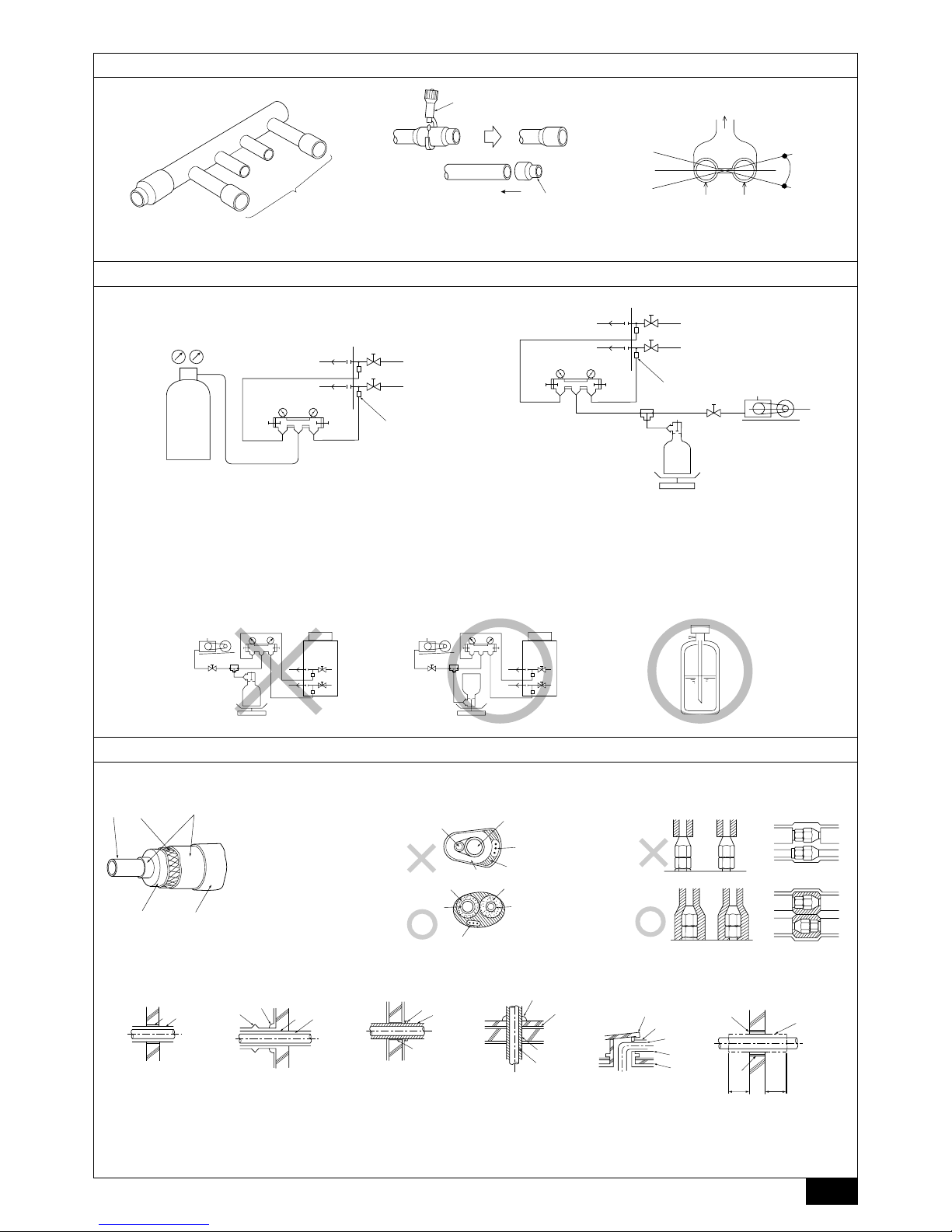
[Fig. 9.2.5] (P.5)
A Close-packed packing B Hollow packing
• After evacuation and refrigerant charge, ensure that the handle is fully open. If
operating with the valve closed, abnormal pressure will be imparted to the
high- or low-pressure side of the refrigerant circuit, or a shortage of oil in the
compressor may occur due to lack of oil flow between units, giving damage to
the compressor, four-way valve, etc.
•
For evacuating, be sure to provide an oil balance pipe between the variable
capacity and constant capacity units.
• Determine the amount of additional refrigerant charge by using the formula,
and charge refrigerant additionally through the service port after completing
piping connection work.
• After completing work, shut the service port and cap tightly so that gas leaking
does not occur.
[Fig. 9.2.6] (P.5)
<A> [Ball valve (liquid side)]
<B> [Ball valve (gas side)]
<C> [Ball valve (oil balance side)]
The unit is set vertically between the compressor and control box.
<D> (This figure shows the valve in the fully open state.)
A Valve stem
[Fully closed at the factory, when connecting the piping, when evacuating, and
when charging additional refrigerant. Open fully after the operations above are
completed.]
B Stopper pin [Prevents the valve stem from turning 90° or more.]
C Packing (accessory)
D Connecting pipe (accessory)
[Use packing and securely install this pipe to the valve flange so that gas leakage will not occur. (Tightening torque: 25 N·m (250 kg·cm)) Coat both surfaces
of the packing with refrigerating machine oil (R407C: Ester oil, ether oil or
alkylbenzene [small amount])]
E Open (Operate slowly)
F Cap, copper packing
[Remove the cap and operate the valve stem. Always reinstall the cap after
operation is completed. (Valve stem cap tightening torque: 25 N·m (250 kg·cm)
or more)]
G Service port
[Use this port to evacuate the refrigerant piping and add an additional charge
at site.
Open and close the port using a double-ended wrench.
Always reinstall the cap after operation is completed. (Service port cap tightening torque: 14 N·m (140 kg·cm) or more)]
H Flare nut
[Tightening torque: 55 N·m (550 kg·cm)
Use a double spanner to open and close. Apply a coat of refrigerating machine
oil (R407C: Ester oil, ether oil or alkylbenzene [small amount]) to the flare
bonding surface.]
I ø28.58
J To distributor (gas) inside variable capacity unit
K ø12.7
L To distributor (liquid)
M To variable capacity unit
N Fastening plate
Warning:
Be sure to remove the connecting pipe from the ball valve, and braze it outside the unit.
- If brazed while mounted, the ball valve is heated and could result in cracking or
gas leaks. The wiring inside the unit could also be burned.
Appropriate tightening torque by torque wrench:
Copper pipe external dia. (mm) Tightening torque (N·m) / (kg·cm)
ø6.35 14 to 18 / 140 to 180
ø9.52 35 to 42 / 350 to 420
ø12.7 50 to 57.5 / 500 to 575
ø15.88 75 to 80 / 750 to 800
ø19.05 100 to 140 / 1000 to 1400
Tightening angle standard:
Pipe diameter (mm) Tightening angle (°)
ø6.35, ø9.52 60 to 90
ø12.7, ø15.88 30 to 60
ø19.05 20 to 35
[Fig. 9.2.7] (P.5)
Note:
If a torque wrench is not available, use the following method as a standard:
When you tighten the flare nut with a wrench, you will reach a point where
the tightening torque will abruptly increase. Turn the flare nut beyond this
point by the angle shown in the table above.
Caution:
• Always remove the connecting pipe from the ball valve and braze it outside the unit.
- Brazing the connecting pipe while it is installed will heat the ball valve and
cause trouble or gas leakage. The piping, etc. inside the unit may also be
burned.
• Use ester oil, ether oil or alkylbenzene (small amount) as the refrigerating machine oil to coat flares and flange connections. (For R407C models)
- The refrigerating machine oil will degrade if it is mixed with a large amount of
mineral oil.
• Do not use a leak detection additive.
9.3. Oil balance pipe connection method
• Oil balance piping can be taken out from the front, bottom or side of the unit
(left side for the variable capacity unit, right side for the constant capacity unit).
• Connect piping and operate valves exactly as described below (for details, see
item 9.2.).
1 After connecting oil balance pipe, be sure to evacuate using the service
port of the variable capacity unit side valve.
2 After evacuating, be sure to fully open each valve stem. If you operate with
the valve closed, a shortage of oil in the compressor may occur due to lack
of oil flow between units, which could result in damage to the compressor.
3 After completing work, shut the cap of the service port and handle section
tightly so that gas leaking does not occur.
Warning:
Failure to connect the oil balance pipe will result in the compressor being
damaged.
• Provide 10 mm of clearance between the variable capacity and constant capacity units. Position the variable capacity unit so that its front is facing on the
right side and the constant capacity unit so that its front is facing on the left.
Connect the oil balance pipe for the distributor kit is attached with constant
capacity unit according to the following procedure.
1 Open the knock-out holes of the left side panel for the variable capacity
unit, and the right side panel for the constant capacity unit.
2 After installing the units, flare-connect the piping included with the unit
(ø12.7).
3 Block the clearance between units with the 2 seals included with the con-
stant capacity unit.
4 Put on pipe cover between oil balance pipe 2 and oil balance pipe 3 (ac-
cessory in distributor kit).

17
GB
D
F
INL
E
PGRRUTR
[Fig. 9.3.1] (P.5)
<A> (Constant capacity unit) <B> (Variable capacity unit)
<C> Compressor <D> Control box
A 10 mm (clearance between units) B Right side panel
C Left side panel D Ball valve (oil balance) ø12.7 (flare)
E Oil balance pipe 1 (accessory) F Oil balance pipe 2 (accessory)
G Flare connection
Tightening torque is 55 N·m (550 kg·cm).
Open and close using a double spanner. Apply a coat of refrigerating machine oil on both sides of the flare contact surface.
H Oil balance pipe 3 (accessory) I Seal material (2 pieces, included)
J Through holes for oil balance pipe and transmission cables
K Brazing L Pipe cover (accessory)
• If the oil balance piping for the constant capacity unit from the front of the unit
is taken out, bend the piping as shown in the Fig. 9.3.2. (When doing so, ensure that the piping doesn’t touch the compressor or other parts.)
[Fig. 9.3.2] (P.6)
<A> (Constant capacity unit) <B> Compressor
<C> Control box <D> Distributor kit
A Front panel
B Knock out holes for taking out oil balance pipe from front surface
C Ball valve (oil balance) ø12.7 (flare)
D Oil balance pipe (Bend piping at the site)
9.4. Distributor (gas) connection method
These accessory parts are required to make connection between variable capacity unit and constant capacity unit when using the unit (PUHY-P600/650/700/750).
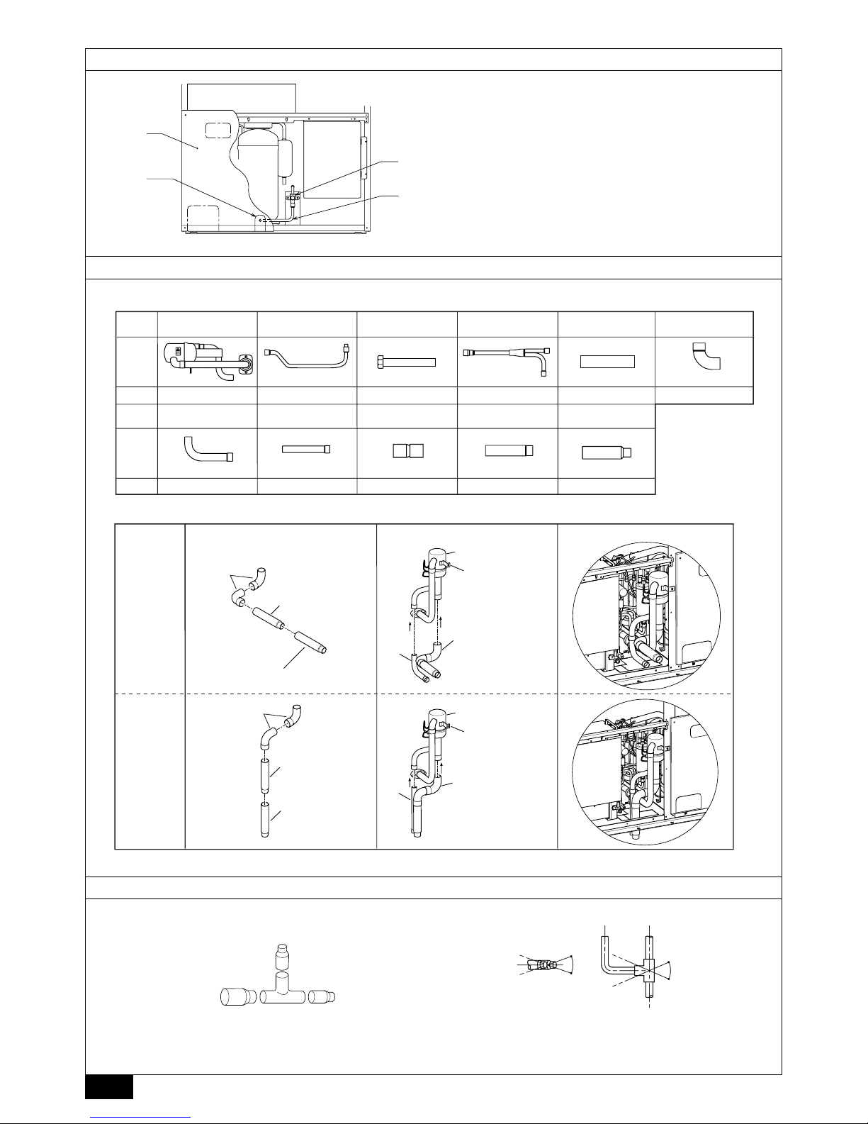
[Fig. 9.4.1] (P.6) <Parts in Distributor kit>
A Distributor (gas) × 1 B Oil balance pipe 2 × 1
C Oil balance pipe 3 × 1 D Distributor (liquid) × 1
E Pipe cover × 1 F Elbow (OD44.45 - ID44.45) × 2
G Connecting pipe (OD28.58 - ID28.58) × 1
H Connecting pipe (OD28.58 - ID28.58) × 1
I Connecting pipe (OD44.45 - ID41.28) × 1
J Connecting pipe (OD44.45 - ID38.1) × 1
K Connecting pipe (OD38.1 - ID34.92) × 1
There are two ways to make the connection between variable capacity unit and
constant capacity unit:
1) Taking out piping from frontward.
2) Taking out piping from downward.
[Fig. 9.4.2] (P.6)
F Elbow (OD44.45 - ID44.45)
G Connecting pipe (OD28.58 - ID28.58)
H Connecting pipe (OD28.58 - ID28.58)
I Connecting pipe (OD44.45 - ID41.28)
J Connecting pipe (OD44.45 - ID38.1)
K Connecting pipe (OD38.1 - ID34.92) (For P600 type only)
Step (1)
Braze the elbow F and connecting pipe I, J, K each other outside the unit
according to figure shown above.
For P650 to 750 type: I connecting pipe
For P600 type: J, K connecting pipe
Step (2)
Remove the copper cap and rubber packing attached to the piping and flange of
the distributor (gas).
Braze the assembly in step (1) and connecting pipe G, H to distributor (gas) according to figure shown above. When brazing, cool the braze parts of the distributor side with wet cloth to prevent heating by brazing.
Step (3)
Insert the assembly in step (2) into the variable capacity unit and connect to the
flange of the ball valve (gas side) (Use a socket wrench and socket wrench extension). When doing so, be sure to mount the included packing between the ball
valve (gas side) and flange of the distributor. Fasten the plate of the distributor
(gas) to the frame of the unit with screw.
Caution:
When brazing, cool with a waste cloth dampened with water so that the flange
and ends of the distributor side piping don’t get heated.
- Parts could be damaged if not cooled sufficiently.
Note:
• Distributor kit is attached with constant capacity unit.
• Reset the fin guard of constant capacity unit before the unit works.
• Throw out the support plate that used for fixing the distributor kit.
9.5. How to install branch pipe
For detail, please observe the instruction manual attached to the optional refrigerant branch kit.
[Fig. 9.5.1] (P.6)
Å Joint
A To outdoor unit B To branch piping or indoor unit
C Horizontal D Within ± 15°
E Facing upwards (Facing downwards is not possible)
• Apart from the CMY-Y202-F and CMY-Y302-F gas side, there are no restrictions on the posture for attaching joints.
• Ensure that the branch pipes for the CMY-Y202-F and CMY-Y302-F gas side
are attached horizontally or facing upwards (see Fig. 9.5.1).
• There is no limitation on the joint mounting configuration.
• If the diameter of the refrigerant piping selected by the procedures described
on pages 3 to 4 is different from the size of the joint, match the sizes using a
deformed joint. The deformed joint is included with the kit.
[Fig. 9.5.2] (P.7)
Å Header
A To outdoor unit B To indoor unit
C Pipe cutter D or
E Deformed joint
• No restriction is applied to the mounting posture of the header.
• If the diameter of the refrigerant piping selected using the procedures described
on pages 3, 4 and the size of the joint is different, match the sizes using a
deformed joint. The deformed joint is included with the kit.
• When the number of pipes to be connected is smaller than the number of
header branches, install a cap to the unconnected branches. The cap is included with the kit.
[Fig. 9.5.3] (P.7)
Å Distributor (liquid) (accessory)
A Field piping B Variable capacity unit
C Constant capacity unit
• Mount the distributor (liquid, attachment part in constant capacity unit) so that
it is within ±15° in relation to the horizontal plane (see Fig. 9.5.3).
Note:
• Distributor (liquid) is attached with distributor kit in constant capacity
unit.
9.6 Airtight test, evacuation and refrigerant
charging
1 Airtight test
Perform with the ball valve of the outdoor unit closed, and pressurize the connection piping and the indoor unit from the service port provided on the ball
valve of the outdoor unit. (Always pressurize from both the gas pipe and the
liquid pipe service ports.)
[Fig. 9.6.1] (P.7)
A Nitrogen gas B To indoor unit C System analyzer
D Lo knob E Hi knob F Ball valve
G Liquid pipe H Gas pipe I Outdoor unit
J Service port
<For R407C models>
The method of conducting the airtight test is basically the same as for R22 models.
However, since the restrictions have a large affect on deterioration of the refrigerating machine oil, always observe them. Also, with nonazeotropic refrigerant (R407C,
etc.), gas leakage causes the composition to change and affects performance.
Therefore, perform the airtightness test cautiously.
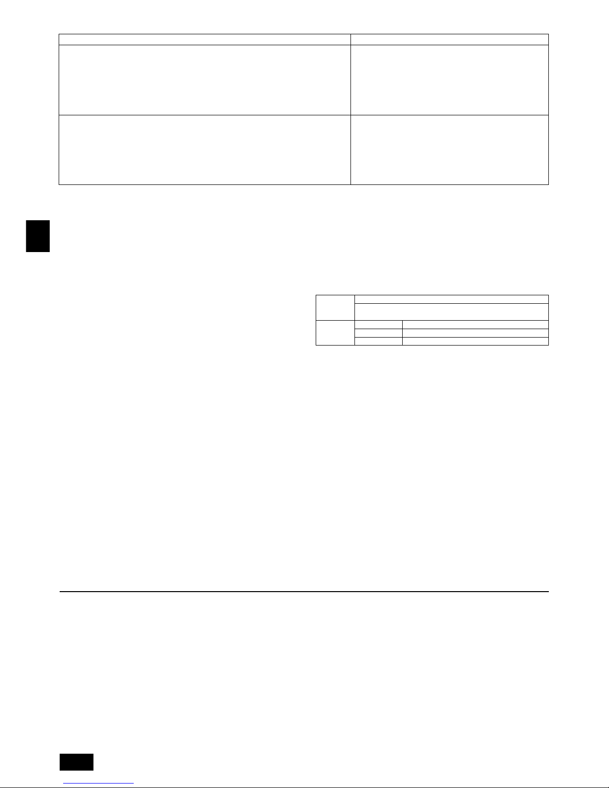
18
GB
D
F
INL
E
PGRRUTR
2 Evacuation
Evacuate with the ball valve of the outdoor unit closed and evacuate both the
connection piping and the indoor unit from the service port provided on the ball
valve of the outdoor unit using a vacuum pump. (Always evacuate from the
service port of both the gas pipe and the liquid pipe.) After the vacuum reaches
650 Pa [abs], continue evacuation for at least one hour or more.
* Never perform air purging using refrigerant.
[Fig. 9.6.2] (P.7)
A System analyzer B Lo knob C Hi knob
D Ball valve E Liquid pipe F Gas pipe
G Service port H Three-way joint I Valve
J Valve K Cylinder L Scale
M Vacuum pump
Note:
• Always add an appropriate amount of refrigerant. Also always seal the
system with liquid refrigerant. Too much or too little refrigerant will cause
trouble.
• Use a gauge manifold, charging hose, and other parts for the refrigerant
indicated on the unit.
• Use a graviometer. (One that can measure down to 0.1 kg.)
• Use a vacuum pump with a reverse flow check valve. (For R407C models)
(Recommended vacuum gauge: ROBINAIR 14830A Thermistor Vacuum
Gauge)
Also use a vacuum gauge that reaches 0.5 Torr or greater after operating
for five minutes.
3 Refrigerant Charging (For R407C models)
Since the refrigerant used with the unit is nonazerotropic, it must be charged in the
liquid state. Consequently, when charging the unit with refrigerant from a cylinder,
if the cylinder does not have a syphon pipe, charge the liquid refrigerant by turning
the cylinder upside-down as shown below. If the cylinder has a syphon pipe like
that shown in the figure at the right, the liquid refrigerant can be charged with the
cylinder standing upright. Therefore, give careful attention to the cylinder specifications. If the unit should be charged with gas refrigerant, replace all the refrigerant
with new refrigerant. Do not use the refrigerant remaining in the cylinder.
[Fig. 9.6.3] (P.7)
9.7 Thermal insulation of refrigerant piping
Be sure to give insulation work to refrigerant piping by covering liquid pipe and gas
pipe separately with enough thickness heat-resistant polyethylene, so that no gap
is observed in the joint between indoor unit and insulating material, and insulating
materials themselves. When insulation work is insufficient, there is a possibility of
condensation drip, etc. Pay special attention to insulation work to ceiling plenum.
[Fig. 9.7.1] (P.7)
A Steel wire B Piping
C Asphaltic oily mastic or asphalt D Heat insulation material A
E Outer covering B
Glass fiber + Steel wire
Adhesive + Heat - resistant polyethylene foam + Adhesive tape
Indoor Vinyl tape
Floor exposed Water-proof hemp cloth + Bronze asphalt
Outdoor Water-proof hemp cloth + Zinc plate + Oily paint
Note:
• When using polyethylene cover as covering material, asphalt roofing shall
not be required.
• No heat insulation must be provided for electric wires.
[Fig. 9.7.2] (P.7)
A Liquid pipe B Gas pipe C Electric wire
D Finishing tape E Insulater
[Fig. 9.7.3] (P.7)
Penetrations
[Fig. 9.7.4] (P.7)
<A> Inner wall (concealed) <B> Outer wall
<C> Outer wall (exposed) <D> Floor (fireproofing)
<E> Roof pipe shaft
<F> Penetrating portion on fire limit and boundary wall
A Sleeve B Heat insulating material
C Lagging D Caulking material
E Band F Waterproofing laye
G Sleeve with edge H Lagging material
I Mortar or other incombustible caulking
J Incombustible heat insulation material
When filling a gap with mortar, cover the penetration part with steel plate so that
the insulation material will not be caved in. For this part, use incombustible materials for both insulation and covering. (Vinyl covering should not be used.)
Restriction
• If a flammable gas or air (oxygen) is used as the pressurization
gas, it may catch fire or explode.
• Do not use a refrigerant other than that indicated on the unit.
• Sealing with gas from a cylinder will cause the composition of
the refrigerant in the cylinder to change. (For R407C models)
• Use a pressure gauge, charge box, and other parts especially for
R407C. (For R407C models)
• An electric leak detector for R22 cannot detect leaks of R407C.
• Do not use a haloid torch. (Leaks cannot be detected.)
Airtight test procedure
1. Nitrogen gas pressurization
(1) After pressurizing to the design pressure (2.94 MPa) using nitrogen gas, let stand for about
one day. If the pressure does not drop, airtightness is good.
However, if the pressure drops, since the leaking point is unknown, the following bubble test
may also be performed.
(2)
After the pressurization described above, spray flare connection parts, brazed parts, flanges, and
other parts that may leak with a bubbling agent (Kyuboflex, etc.) and visually check for bubbles.
(3) After the airtight test, wipe off the bubbling agent.
2. Pressurization using refrigerant gas and nitrogen gas
(1) Pressurizing to a gas pressure of approximately 0.2 MPa, pressurize to the design pressure
(2.94 MPa) using nitrogen gas.
However, do not pressurize at one time. Stop during pressurization and check that the pressure does not drop.
(2) Check for gas leaks by checking the flare connection parts, brazed parts, flanges, and other
parts which may leak using an R407C compatible electric leak detector.
(3) This test may be used together the with bubble type gas leak test.
Heat
insulation
material A
Outer
covering B
7 Only the transmission line specified should be connected to the terminal block
for outdoor unit transmission.
(Transmission line to be connected with indoor unit and constant capacity unit:
Terminal block TB3 for transmission line, Other : Terminal block TB7 for centralized control)
Erroneous connection does not allow the system to operate.
8 In case to connect with the upper class controller or to conduct group opera-
tion in different refrigerant systems, the control line for transmission is required
between the outdoor units and each other.
Connect this control line between the terminal blocks for centralized control.
(2-wire line with no polarity)
When conducting group operation in different refrigerant systems without connecting to the upper class controller, replace the insertion of the short circuit
connector from CN41 of one outdoor unit to CN40.
9 Group is set by operating the remote controller.
10. Wiring
10.1. Caution
1 Follow ordinance of your governmental organization for technical standard re-
lated to electrical equipment, wiring regulations and guidance of each electric
power company.
2 Wiring for control (hereinafter referred to as transmission line) shall be (5 cm or
more) apart from power source wiring so that it is not influenced by electric
noise from power source wiring. (Do not insert transmission line and power
source wire in the same conduit.)
3 Be sure to provide designated grounding work to outdoor unit.
4 Give some allowance to wiring for electrical part box of indoor and outdoor
units, because the box is sometimes removed at the time of service work.
5 Never connect the main power source to terminal block of transmission line. If
connected, electrical parts will be burnt out.
6 Use 2-core shield cable for transmission line. If transmission lines of different
systems are wired with the same multiplecore cable, the resultant poor transmitting and receiving will cause erroneous operations.
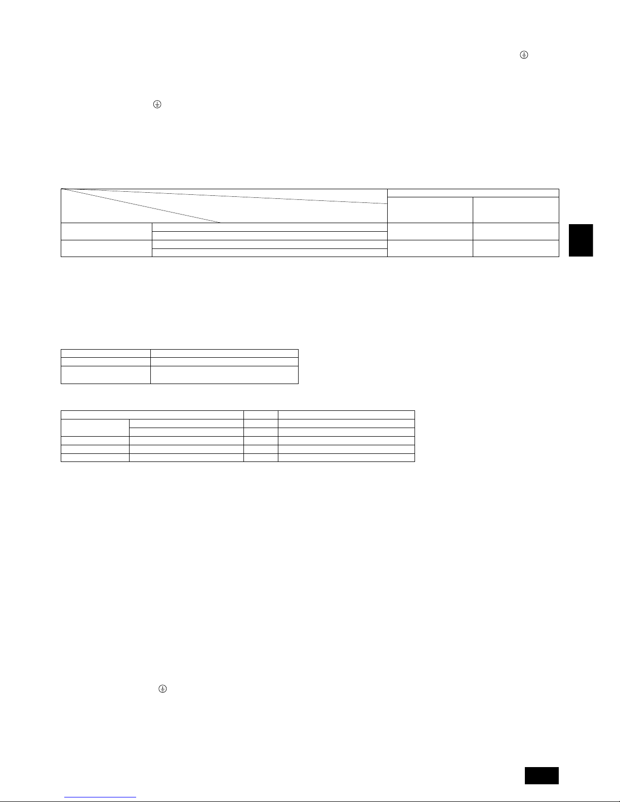
19
GB
D
F
INL
E
PGRRUTR
10.3. Wiring transmission cables
1 Connecting a transmission booster unit
A transmission booster (RP) is required when the number of connected indoor unit models in a cooling system exceeds the number of models specified in the chart below.
* The maximum number of units that can be controlled is determined by the indoor unit model, the type of remote controller and their capabilities.
The number of indoor units and the total number of remote controllers is displayed within the parenthesis ( ).
*1 If even one unit that is higher than 200 exists in the cooling system, the maximum capacity will be “200 or higher”.
Remote controller
MA R/C M-NET R/C
32 20 (40)
26 16 (32)
(*1)
Capability of the
connected indoor units
Remote controller type
Number of connected indoor units that can be
connected without a RP
200 or lower
200 or higher
No OS
One OS
No OS
One OS
2 Types of control cables
1. Wiring transmission cables
• Types of transmission cables: Shielding wire CVVS or CPEVS
• Cable diameter: More than 1.25 mm
2
• Maximum wiring length: Within 200 m
2. Remote control cables
3 Wiring examples
• Controller name, symbol and allowable number of controllers.
*1 A transmission booster (RP) may be required depending on the number of connected indoor unit controllers.
Example of a group operation system with multiple outdoor units (Shielding wires and address setting are
necessary.)
<Examples of Transmission Cable Wiring>
[Fig. 10.3.1] M-NET Remote controller (P.8)
[Fig. 10.3.2] MA Remote controller (P.9)
[Fig. 10.3.3] Transmission booster unit (P.9)
A Group 1 B Group 4 C Group 5 D Shielded Wire E Sub Remote Controller
( ) Address
<Wiring Method and Address Settings>
a. Always use shielded wire when making connections between the variable capacity unit controller (OC), the indoor unit (IC) and constant capacity unit controller (OS) as
well for all OC-OC, and IC-IC wiring intervals.
b. Use feed wiring to connect terminals M1 and M2 and the ground terminal on the transmission cable terminal block (TB3) of each variable capacity unit controller (OC),
and constant capacity unit controller (OS) to terminals M1, M2 and terminal S on the transmission cable block of the indoor unit (IC) and BC controller (BC, BS*1).
(*1: Case of R2/WR2/BIG-R2 series)
c. Connect terminals 1 (M1) and 2 (M2) on the transmission cable terminal block of the indoor unit (IC) that has the most recent address within the same group to the
terminal block on the remote controller (RC).
d. Connect together terminals M1, M2 and terminal S on the terminal block for central control (TB7) for the outdoor unit (OC).
e. On one outdoor unit only, change the jumper connector on the control panel from CN41 to CN40.
f. Connect the terminal S on the terminal block for central control (TB7) for the outdoor unit (OC) for the unit into which the jumper connector was inserted into CN40 in Step
above to the ground terminal
in the electrical component box.
g. Set the address setting switch as follows.
* To set the outdoor unit address to 100, the outdoor address setting switch must be set to 50.
To set the M-NET R/C address to 200, the M-NET R/C address setting switch must be set to 00.
Kind of remote control cable
Cable diameter
Remarks
(case of M-NET R/C)
2-core cable (unshielded)
0.3 to 1.25 mm
2
When 10 m is exceeded, use cable with the same
specifications as (1) Transmission line wiring
Name Code Possible unit connections
Outdoor unit
Indoor unit
Remote controller
Other
Variable capacity unit controller
Constant capacity unit controller
Indoor unit controller
Remote controller (*1)
Transmission booster unit
–
1 unit per 1 OC
2 to 32 units per 1 OC (*1)
2 units maximum per group
0 to 1 unit per 1 OC (*1)
OC
OS
IC
RC
RP
10.2. Control box and connecting position of
wiring
1. Connect the indoor unit transmission line to transmission terminal block (TB3),
or connect the wiring between outdoor units or the wiring with the central control system to the central control terminal block (TB7).
When using shielded wiring, connect shield ground of the indoor unit transmission line to the earth screw (
) and connect shield ground of the line between
outdoor units and the central control system transmission line to the shield (S)
terminal of the central control terminal block (TB7) shield (S) terminal. In addi-
tion, in the case of outdoor units whose power supply connector CN41 has
been replaced by CN40, the shield terminal (S) of terminal block (TB7) of the
central control system should also be connected to the ground (
).
[Fig. 10.2.1] / [Fig. 10.2.2] (P.8)
A Power source B Transmission line
2. Conduit mounting plates (ø27) are provided. Pass the power supply and trans-
mission wires through the appropriate knock-out holes, then remove the knockout piece from the bottom of the terminal box and connect the wires.
3. Fix power source wiring to terminal box by using buffer bushing for tensile
force (PG connection or the like).
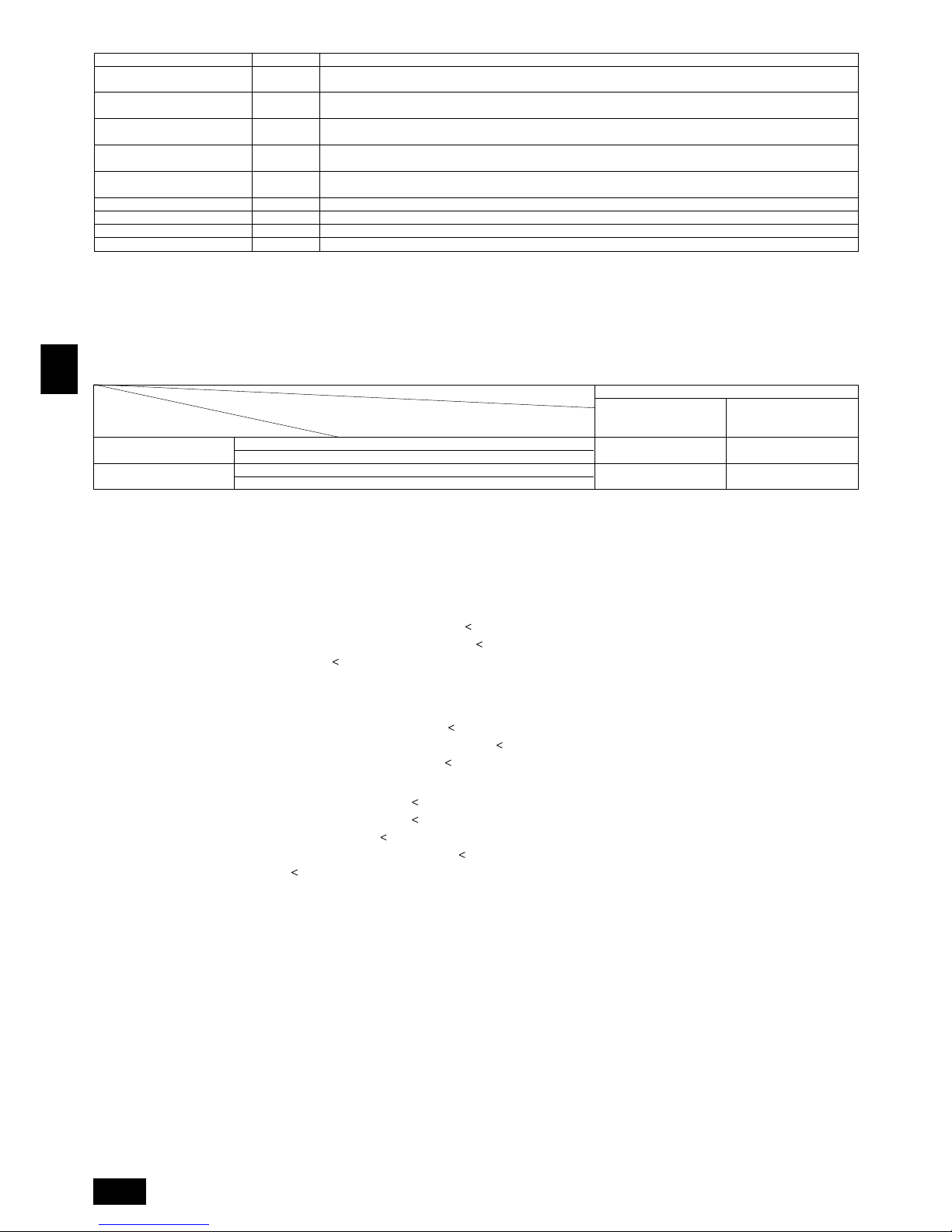
20
GB
D
F
INL
E
PGRRUTR
h. The group setting operations among the multiple indoor units is done by the remote controller (RC) after the electrical power has been turned on.
i. When using a transmission booster (RP)
• Let the number of indoor units and remote control units connected be within the limit for the number of units shown in the following table for the total number of units
connected between the outdoor unit (OC) and the transmission booster (RP) N
1 and the number of units connected after the transmission booster (RP) N2.
• Connect the power supply ground to the transmission booster (RP) securely.
Connect the transmission lines of the outdoor unit side to terminals A and B of transmission line terminal block 1 (TB2) of the transmission booster (RP).
Connect the transmission lines of the expansion indoor unit side to terminals A and B of the of transmission line terminal block 2 (TB3) of the transmission booster (RP).
The number of indoor units and the total number of remote controllers is displayed within the parenthesis ( ).
*1 If even one unit that is higher than 200 exists in the cooling system, the maximum capacity will be “200 or higher”.
<Branch Setting> *Case of R2/WR2/BIG-R2 series
Set the indoor unit branch No. switch to the branch No. of the BC controller connecting the piping and that indoor unit.
When using two or more branches, set the lowest branch No.
The indoor unit capacity that can be connected per branch is P80 or less and the number of connectable units is 3.
<Permissible Lengths>
1 M-NET Remote controller
• Max length via outdoor units: L
1+L2+L3+L4 and L1+L2+L3+L5 and L1+L2+L6+L7
=
500 m (1.25 mm2 or more)
• Max transmission cable length: L
1 and L3+L4 and L3+L5 and L6 and L2+L6 and L7
=
200 m (1.25 mm2 or more)
• Remote controller cable length:r
1, r2, r3, r4
=
10 m (0.3 to 1.25 mm2)
If the length exceeds 10 m, use a 1.25 mm
2
shielded wire. The length of this section (L8) should be included in the calculation of the
maximum length and overall length.
2 MA Remote controller
• Max length via outdoor unit (M-NET cable): L
1+L2+L3+L4 and L1+L2+L6+L7
=
500 m (1.25 mm2 or more)
• Max transmission cable length (M-NET cable): L
1 and L3+L4 and L6 and L2+L6 and L7
=
200 m (1.25 mm2 or more)
• Remote controller cable length:c
1 and c1+c2+c3 and c1+c2+c3+c4
=
200 m (0.3 to 1.25 mm2)
3 Transmission booster
• Max transmission cable length (M-NET cable): 1 L
1+L2+L3+L5+L6
=
200 m (1.25 mm2)
2 L
1+L2+L3+L5+L7
=
200 m (1.25 mm2)
3 L
1+L2+L4
=
200 m (1.25 mm2)
4 L
6+L5+L3+L4, L4+L3+L5+L7
=
200 m (1.25 mm2)
• Remote controller cable length: r
1, r2
=
10 m (0.3 to 1.25 mm2)
If the length exceeds 10 m, use 1.25 mm
2
shielded cable and calculate the length of that portion (L4 and L7) as within the total extended
length and the longest remote length.
10.4. Wiring of main power supply and equipment capacity
Schematic Drawing of Wiring (Example)
[Fig. 10.4.1] (P.9)
A Switch (Breakers for wiring) B Breakers for current leakage C Outdoor unit
D Outdoor unit (Variable capacity unit) E Outdoor unit (Constant capacity unit) F Indoor unit
G Pull box H Transmission booster
ÅÅ
ÅÅ
Å Note:
1. The transmission booster may be required according to the number of indoor units connected.
2. For switch capacity, see the installation manual for transmission booster.
Remote controller
MA R/C M-NET R/C
32 20 (40)
26 16 (32)
(*1)
Capability of the
connected indoor units
Remote controller type
Number of connected indoor units that can be
connected without a RP
200 or lower
200 or higher
No OS
One OS
No OS
One OS
Unit Range Setting Method
IC (Main) 01 to 50
Use the most recent address within the same group of indoor units. Make the indoor units address connected to the
BC controller (Slave) larger than the indoor units address connected to the BC controller (Master) (*1)
IC (Sub) 01 to 50
Use an address, other than that of the IC (Main) from among the units within the same group of indoor units. This must
be in sequence with the IC (Main)
Outdoor Unit
51 to 100 Use the most recent address of all the indoor units plus 50
(Variable capacity unit)
Outdoor Unit
(Constant capacity unit)
51 to 100 Variable capacity unit address plus 1
BC controller (Master) (*2) 51 to 100
Outdoor unit address plus 1. When the set indoor unit address duplicates the address of another indoor unit, set the
new address to a vacant address within the setting range.
BC controller (Slave) (*1) 51 to 100 Lowest address within the indoor units connected to the BC controller (slave) plus 50
M-NET R/C (Main) 101 to 150 Set at an IC (Main) address within the same group plus 100
M-NET R/C (Sub) 151 to 200 Set at an IC (Main) address within the same group plus 150
MA R/C – Unnecessary address setting (Necessary main/sub setting)
*1: Case of BIG-R2 series, *2: Case of R2/WR2/BIG-R2 series
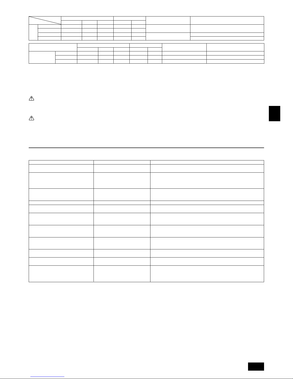
21
GB
D
F
INL
E
PGRRUTR
Display of remote controller
“Cooling (heating)” flashes
Normal display
Normal display
Defrost display
No lighting
Heat ready
Normal display
“HO” flashes
Light out
Normal display
Cause
When another indoor unit is performing the heating (cooling) operation, the cooling (heating) operation is not performed.
Because of the control operation of auto vane, it may change over to horizontal
blow automatically from the downward blow in cooling in case the downward
blow operation has been continued for 1 hour. At defrosting in heating, hot adjusting and thermostat OFF, it automatically changes over to horizontal blow.
Ultra-low speed operation is commenced at thermostat OFF.
Light air automatically changes over to set value by time or piping temperature at
thermostat ON.
The fan is to stop during defrosting.
Fan is to run for 1 minute after stopping to exhaust residual heat (only in heating).
Ultra low-speed operation for 5 minutes after SW ON or until piping temperature
becomes 35°C, low speed operation for 2 minutes thereafter, and then set notch
is commenced. (Hot adjust control)
When the outdoor unit is being cooled and the refrigerant is resting, warming up
operation is performed for at least 35 minutes to warm the compressor.
During this time, only the fan operates.
System is being driven.
Operate remote controller again after “HO” disappear.
After a stop of cooling operation, unit continues to operate drain pump for three
minutes and then stops it.
Unit continues to operate drain pump if drainage is generated, even during a
stop.
The fan of constant capacity unit is run automatically in order not to accumulate
the refrigerant.
Phenomenon
Indoor unit does not perform cooling (heating) operation.
The auto vane runs freely.
Fan setting changes during heating.
Fan stops during heating operation.
Fan does not stop while operation has been
stopped.
No setting of fan while start SW has been
turned on.
Outdoor unit does not operate by turning
switch on.
Indoor unit remote controller shows “HO” indicator for about two minutes when turning
ON universal power supply.
Drain pump does not stop while unit has been
stopped.
Drain pump continues to operate while unit
has been stopped.
When the variable capacity unit is running,
the fan of the constant capacity unit runs even
though the constant capacity unit isn’t running.
11. Test run
11.1. The following phenomena do not represent trouble (emergency)
1. Use a separate power supply for the outdoor unit and indoor unit.
2. Bear in mind ambient conditions (ambient temperature,direct sunlight, rain water,etc.) when proceeding with the wiring and connections.
3. The wire size is the minimum value for metal conduit wiring. The power cord size should be 1 rank thicker with consideration of voltage drops.
Make sure the power-supply voltage does not drop more than 10 %.
4. Specific wiring requirements should adhere to the wiring regulations of the region.
5. Power supply cords of parts of appliances for outdoor use shall not be lighter than polychloroprene sheathed flexible cord (design 245 IEC57).
6. A switch with at least 3 mm contact separation in each pole shall be provided by the Air conditioner installation.
Warning:
• Be sure to use specified wires to connect so that no external force is imparted to terminal connections. If connections are not fixed firmly, it may cause
heating or fire.
• Be sure to use the appropriate type of overcurrent protection switch. Note that generated overcurrent may include some amount of direct current.
Caution:
• Some installation site may require attachment of an earth leakage breaker. If no earth leakage breaker is installed, it may cause an electric shock.
• Do not use anything other than breaker and fuse with correct capacity. Using fuse and wire or copper wire with too large capacity may cause a malfunction
of unit or fire.
75 A 100 mA 0.1 sec. or less
30 A 100 mA 0.1 sec. or less
40 A 100 mA 0.1 sec. or less
16 A or less
25 A or less
32 A or less
Wire thickness (mm2)
Main cable
1.5
2.5
4.0
Model
Branch
1.5
2.5
4.0
Switch (A)
Capacity
16
25
32
Fuse
16
25
32
Ground
1.5
2.5
4.0
Breaker for wiring (NFB) Breaker for current leakage
20 A 30 mA 0.1 sec. or less
30 A 30 mA 0.1 sec. or less
40 A 30 mA 0.1 sec. or less
20 A
30 A
40 A
Total operating
current of the
indoor units
PUHY-P400
PUHY-P500
PUHN-P200
PUHN-P250
Outdoor
unit
Minimum wire thickness (mm2)
Main cable
10.0
16.0
4.0
6.0
Model
Branch
–
–
–
–
Switch (A)
Capacity
63
63
32
40
Fuse
63
63
32
40
Ground
10.0
16.0
4.0
6.0
Breaker for wiring (NFB) Breaker for current leakage
75 A
40 A

22
GB
D
F
INL
E
PGRRUTR
Inhalt
1. Sicherheitsvorkehrungen
1.1. Vor Installations- und Elektroarbeiten
s Vor dem Einbau der Anlage vergewissern, daß Sie alle Infor-
mationen über “Sicherheitsvorkehrungen” gelesen haben.
s Die “Sicherheitsvorkehrungen” enthalten sehr wichtige
Sicherheitsgesichtspunkte. Sie sollten sie unbedingt befolgen.
Im Text verwendete Symbole
Warnung:
Beschreibt Vorkehrungen, die beachtet werden sollten, um den Benutzer vor
der Gefahr von Verletzungen oder tödlicher Unfälle zu bewahren.
Vorsicht:
Beschreibt Vorkehrungen, die beachtet werden sollten, um die Anlage vor
Schäden zu bewahren.
Innerhalb der Abbildungen verwendete Symbole
: Verweist auf eine Handlung, die unterbleiben muß.
: Verweist auf wichtige Anweisungen, die befolgt werden müssen.
: Verweist auf ein Teil, das geerdet werden muß.
: Gefahr von elektrischem Schlag. (Dieses Symbol findet sich als Aufkleber
auf der Hauptanlage.) <Farbe: gelb>
Warnung:
Die auf der Hauptanlage angebrachten Aufkleber sorgfältig lesen.
Warnung:
• Bitten Sie Ihren Fachhändler oder einen geprüften Fachtechniker, die Installation der Anlage vorzunehmen.
- Unsachgemäße Installation durch den Benutzer kann Wasseraustritt, Strom-
schläge oder Brände verursachen.
• Die Anlage an einem Ort installieren, der genügend Tragkraft für deren
Gewicht besitzt.
- Bei ungenügender Tragkraft kann das Gerät herunterfallen und Verletzun-
gen verursachen.
• Zur Verdrahtung die angegebenen Kabel verwenden. Die Anschlüsse so
sichern, daß Zugspannung von außen nicht auf die Klemmen wirken kann.
- Falscher Anschluß und falsche Befestigung führen zu Wärmebildung und
verursachen Brände.
• Vorsorge gegen heftige Windstöße und Erdbeben treffen, und die Anlage
an dem angegebenen Ort installieren.
- Durch unsachgemäße Installation kann die Anlage herunterfallen und Ver-
letzungen verursachen.
• Stets einen Filter und sonstiges Zubehör gemäß Angaben von Mitsubishi
Electric verwenden.
- Einen geprüften Techniker bitten, die Zusatzeinrichtungen zu installieren.
Unsachgemäße Installation durch den Benutzer kann zu Wasseraustritt,
Stromschlägen oder Bränden führen.
• Die Anlage niemals selbst reparieren. Wenn die Anlage repariert werden
muß, wenden Sie bitte sich an den Fachhändler.
- Wenn die Anlage unsachgemäß repariert wird, kann dies zu Wasseraustritt,
Stromschlägen oder Bränden führen.
• Nicht die Wärmetauscherleitung berühren.
- Unsachgemäße Handhabung kann zu Verletzungen führen.
• Wenn Kältemittelgas während der Installationsarbeiten austritt, den Raum
gründlich lüften.
- Wenn das Kältemittelgas auf offenes Feuer trifft, wird giftiges Gas freige-
setzt.
• Die Anlage gemäß Anweisungen in diesem Installations-handbuch installieren.
- Bei unsachgemäßer Installation kann dies zu Wasseraustritt, Stromschlä-
gen oder Bränden führen.
• Elektroarbeiten durch einen zugelassenen Fachelektriker in Übereinstim-
mung mit dem “Electric Facility Engineering Standard” - (Technische
Normen für Elektroeinrichtungen), den “Interior Wire Regulations” - (Vor-
schriften zur Innenverdrahtung) und den in diesem Handbuch gegebenen Anweisungen vornehmen. Anlage auch immer an einen gesonderten Stromkreis anschließen.
- Wenn die Leistung der Stromquelle ungenügend ist oder die Elektroarbeiten
unsachgemäß ausgeführt wurden, kann dies zu Stromschlägen und zu Bränden führen.
• Die Abdeckung der Elektroanschlüsse der Außenanlage (Abdeckplatte)
fest anbringen.
- Wenn die Abdeckung der Elektroanschlüsse (Abdeckplatte) nicht sachge-
mäß angebracht wurde, kann Staub oder Wasser in die Außenanlage eindringen und Brände oder Stromschläge verursachen.
• Beim Verbringen der Anlage an einen anderen Standort, Anlage nicht mit
einem anderen Kältemittel als dem auf der Anlage angegebenen Kälte-
mittel (R407C) füllen.
- Wenn das ursprüngliche Kältemittel mit einem anderen Kältemittel oder mit
Luft vermischt wird, kann dies zu Fehlfunktionen des Kältemittelkreislaufs
führen und die Anlage beschädigt werden.
• Wenn die Anlage in einem kleinen Raum installiert wird, müssen Maß-
nahmen ergriffen werden, damit die Kältemittelkonzentration auch bei
Kältemittelaustritt den Sicherheitsgrenzwert nicht überschreitet.
- Befragen Sie einen Fachhändler bezüglich geeigneter Maßnahmen zur Ver-
hinderung des Überschreitens des Grenzwertes. Sollte durch Austreten von
Kältemittel das Überschreiten des Grenzwertes erfolgen, besteht wegen
möglichem Sauerstoffmangel im Raum Gesundheitsgefahr.
• Beim Verbringen der Anlage an einen anderen Ort einen Fachhändler
oder einen geprüften Techniker zur Neuaufstellung hinzuziehen.
- Bei unsachgemäßer Installation der Anlage kann Wasser austreten, und es
können Stromschlage oder Brände verursacht werden.
• Nach Abschluß der Installationsarbeiten sicherstellen, daß kein
Kältemittelgas austritt.
- Wenn Kältemittelgas austritt und mit einem Heizgebläse, einem Ofen oder
sonstigen Wärmequellen in Berührung kommt, kann giftiges Gas erzeugt
werden.
• Die Einstellungen der Schutzvorrichtungen nicht neu einrichten oder än-
dern.
- Wenn Druckschalter, Thermoschalter oder eine andere Schutzvorrichtung
kurzgeschlossen oder mit Gewalt betätigt wird oder wenn andere als die von
Mitsubishi Electric angegebenen Teile verwendet werden, besteht Brandoder Explosionsgefahr.
• Zum Entsorgen dieses Gerätes wenden Sie sich an Ihren Fachhändler.
• Der Installateur und der Systemfachmann müssen für die Sicherung ge-
gen Wasseraustritt gemäß den örtlichen Bestimmungen und Normen
sorgen.
- Falls keine örtlichen Bestimmungen bestehen, sind die nachstehenden Nor-
men anzuwenden.
• Besonders darauf achten, einen Aufstellungsort auszuwählen, wie etwa
ein Untergeschoß etc., von dem aus Kältemittelgas nicht in die Atmosphäre entweichen kann, da Kältemittel schwerer als Luft ist.
1. Sicherheitsvorkehrungen .......................................................................... 22
1.1. Vor Installations- und Elektroarbeiten...................................... 22
1.2. Vorsichtsmaßnahmen für Vorrichtungen, die das
Kältemittel R407C verwenden ................................................. 23
1.3. Vor der Aufstellung .................................................................. 23
1.4. Vor dem Einbau (der Ortsveränderung) - Elektroarbeiten ....... 23
1.5. Vor Installationsbeginn ............................................................ 23
2. Kombination mit Innenaggregaten ............................................................ 24
3. Überprüfung des Lieferumfangs ............................................................... 24
4. Kombination mit Außenanlagen ................................................................ 24
5. Vorgeschriebener Freiraum um das Aggregat .......................................... 24
6. Hebemethode ........................................................................................... 25
7. Einbau der Klimaanlage ............................................................................ 25
7.1. Einbau ..................................................................................... 25
7.2. Anschlußrichtung für Kältemittelleitung ................................... 25
8. Installation der Kältemittelleitungen .......................................................... 25
8.1. Vorsicht.................................................................................... 25
8.2. Das Kältemittel Rohrsystem .................................................... 26
9. Zusätzliches Kühlmittel einfüllen ............................................................... 27
9.1. Kalkulation des zusätzlichen Kühlmittels ................................. 27
9.2. Vorsichtsmaßregeln für Rohranschluß/Ventilbetrieb ............... 27
9.3. Verfahren zum Anschluß des Ölausgleichsrohres................... 29
9.4. Verfahren zum Anschluss des Verteilers (Gas) ....................... 30
9.5. Wie eine Rohrverteilung installiert wird ................................... 30
9.6 Überprüfung der Dichtheit, Evakuieren und Einfüllen von
Kältemitteln .............................................................................. 30
9.7 Kältedämmung und Kältemittelleitung..................................... 31
10. Verdrahtung ............................................................................................... 31
10.1. Vorsicht .................................................................................... 31
10.2. Reglerkasten und Kabelanschlußpunkte ................................ 32
10.3. Übertragungskabelanschluß ................................................... 32
10.4. Verdrahtung der Hauptspannungsversorgung und Kapazität
der Einheiten ........................................................................... 34
11. Testbetrieb ................................................................................................ 35
11.1. Die folgenden Symptome sind nicht als Betriebsstörungen
(Notfall) anzusehen ................................................................. 35
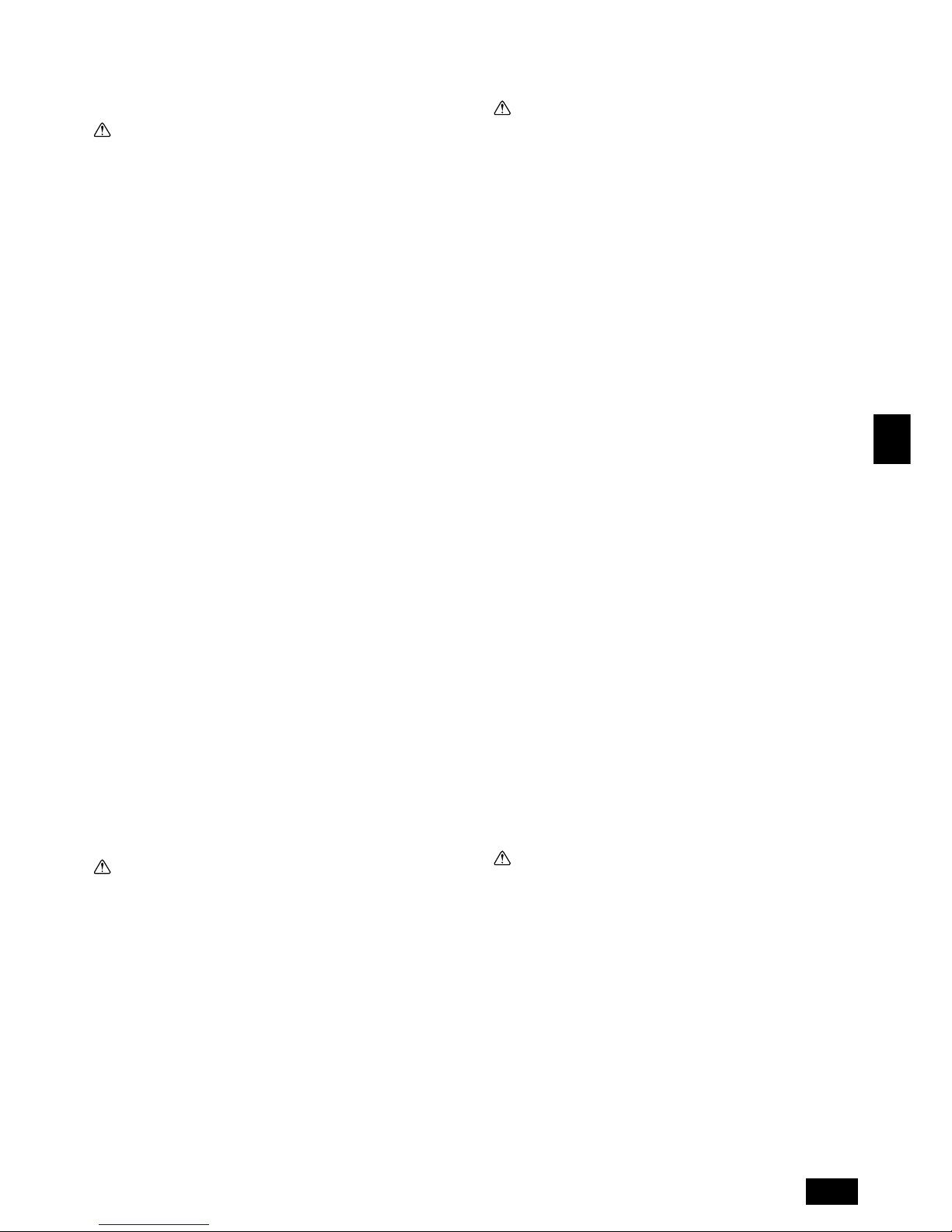
23
GB
D
F
INL
E
PGRRUTR
1.4. Vor dem Einbau (der Ortsveränderung)
- Elektroarbeiten
Vorsicht:
• Erdung der Anlage.
- Die Erdungsleitung nicht an Gas- oder Wasserrohre, Beleuchtungsstäbe oder
an die Erdleitungen von Telefonen anschließen. Unsachgemäße Erdung kann
zu Stromschlägen führen.
• Die Gegenphase von L-Leitungen (L
1, L2, L3) kann festgestellt werden
(Fehlerkabel: 4103), aber die Gegenphase von L-Leitungen und N-Leitung kann nicht festgestellt werden.
- Wenn bei fehlerhafter Verdrahtung Strom zugeführt wird, können einige
Elektroteile beschädigt werden.
• Netzstromleitungen so anbringen, daß keine Zugspannung auf die Kabel
ausgeübt wird.
- Zugspannung kann Kabelbruch, Wärmebildung und Brände verursachen.
• Einen Fehlerstromschutzschalter wie vorgesehen anbringen.
- Wenn kein Fehlerstromschutzschalter angebracht wird, können Stromschlä-
ge verursacht werden.
• Netzstromkabel mit ausreichender Stromstärke und Nennwertauslegung
verwenden.
- Zu kleine Kabel können Fehlstrom verursachen, Wärme erzeugen und Brand
ausbrechen lassen.
• Nur Stromunterbrecher und Sicherungen der angegebenen Leistung verwenden.
- Eine Sicherung oder ein Stromunterbrecher von größerer Stärke oder Stahl-
oder Kupferdraht können zum Ausfall der Anlage oder zum Ausbruch von
Bränden führen.
• Klimageräte nicht waschen.
- Waschen der Anlage kann Stromschläge verursachen.
• Sorgfältig darauf achten, daß die Installationsplatte durch langen Ge-
brauch nicht beschädigt wird.
- Wenn der Schaden nicht behoben wird, kann die Anlage herunterfallen und
Personenschäden oder Schäden an der Einrichtung hervorrufen.
• Zur Gewährleistung eines ordnungsgemäßen Wasserablaufs die Ab-
wasserleitung gemäß Anweisungen in diesem Installationshandbuch installieren. Rohrleitungen mit Wärmeisolierung versehen, um
Kondenswasserbildung zu verhindern.
- Unsachgemäß verlegte Abflußrohre können Wasseraustritt verursachen, was
Schäden an Mobiliar und anderen Einrichtungsgegenständen zur Folge haben kann.
• Beim Transport der Anlage sehr sorgfältig vorgehen.
- Das Gerät wiegt mehr als 20 kg und sollte deshalb nicht von einer Person
allein getragen werden.
- Einige Geräte haben Verpackungsbänder aus PP. PP-Bänder nicht als Trans-
portmittel verwenden. Dies ist gefährlich.
- Nicht die Rippen des Wärmetauschers berühren. Man kann sich dadurch die
Finger verletzen.
- Beim Transport des Außengerätes für Unterstützung an den angegebenen
Stellen am Geräteboden sorgen. Auch die Außenanlage an vier Punkten
unterstützen, damit sie nicht zur Seite wegrutschen kann.
• Verpackungsmaterial sicher entsorgen
- Verpackungsmaterial, wie Nägel und andere Metall- oder Holzteile, können
Stichwunden oder sonstige Verletzungen verursachen.
- Kunststoffbeutel zerreißen und entsorgen, damit Kinder nicht mit ihnen spie-
len. Wenn Kinder mit Kunstoffbeutel spielen, die nicht zerrissen wurden, besteht Erstickungsgefahr.
1.5. Vor Installationsbeginn
Vorsicht:
• Strom mindestens 12 Stunden vor Betriebsbeginn einschalten.
- Betriebsstart unmittelbar nach Einschalten des Netzschalters kann irreversi-
ble Schäden an Innenteilen zur Folge haben. Während der Saison Netzschalter eingeschaltet lassen.
• Schalter nicht mit nassen Fingern berühren.
- Berühren eines Schalters mit nassen Fingern kann einen Stromschlag ver-
ursachen.
• Kältemittelrohrleitung nicht während oder unmittelbar nach Betrieb berühren.
-Während und unmittelbar nach Betrieb sind die Kältemittelrohrleitungen, je
nach Durchfluß des Kältemittels durch die Kältemittelrohrleitung, den Kompressor und andere Teile des Kältemittelkreislaufs, manchmal heiß und
manchmal kalt. Sie können sich die Hände verbrennen oder Frostverletzungen
erleiden, wenn Sie die Kältemittelrohrleitung berühren.
• Klimageräte nicht bei abgenommenen Verkleidungen und Schutzabdeckungen betreiben.
- Drehende, heiße oder unter Hochspannung stehende Teile können Verlet-
zungen verursachen.
• Netzstrom nicht unmittelbar nach Betriebsbeendigung ausschalten.
- Vor Ausschalten des Netzstroms immer mindestens 5 Minuten warten. An-
derenfalls kann es zu Wasseraustritt oder sonstigen Störungen kommen.
•
Während der Wartung nicht die Außenfläche des Kompressors berühren.
- Wenn das Gerät an den Netzstrom angeschlossen ist, aber nicht läuft, ist die
Heizung des Kurbelgehäuses im Kompressor in Betrieb.
1.2. Vorsichtsmaßnahmen für Vorrichtungen, die das Kältemittel R407C verwenden
Vorsicht:
• Kältemittel und Öl
- Das alte Kältemittel und das Kältemaschinenöl in der vorhandenen Rohrleitung enthalten große Mengen Chlor, was zur Qualitätsminderung des
Kältemaschinenöls der neuen Anlage führen kann.
• Für die Kältemittelrohrleitung nahtlose Rohre und Röhren aus Phosphordesoxidiertem Kupfer und entsprechenden Kupferlegierungen verwenden. Außerdem vergewissern, daß die Innen- und Außenflächen der Rohrleitungen sauber und frei von gefährlichem Kupfer, Oxyden, Staub/
Schmutz, Metallbearbeitungsrückständen, Ölen, Feuchtigkeit oder ande-
ren Verunreinigungen sind.
- Verunreinigungen auf der Innenseite der Kältemittelrohrleitungen können dazu
führen, daß das Kältemittelrestöl verdirbt.
• Die bei der Installation verwendete Rohrleitung in einem geschlossenen
Raum aufbewahren und beide Enden bis unmittelbar vor dem Hartlöten
geschlossen halten. (Krümmer und andere Rohrverbinder in einem
Kunststoffbeutel aufbewahren).
- Wenn Staub, Schmutz oder Wasser in den Kältemittelkreislauf gelangt, kann
dies zu einer Qualitätsminderung des Öls und zu Kompressorstörungen füh-
ren.
• Zum Beschichten der Konus- und Flanschanschlüsse Esteröl/Ätheröl oder
Alkylbenzol (kleine Menge) als Kältemaschinenöl verwenden.
- Das Kältemaschinenöl zersetzt sich, wenn es mit größeren Mengen Mine-
ralöl vermischt wird.
• Zur Füllung des Systems flüssiges Kältemittel verwenden.
- Wenn Kältemittelgas zur Füllung des Systems verwendet wird, ändert sich
die Zusammensetzung des Kältemittels im Zylinder, so daß die Leistung
abfallen kann.
• Kein anderes Kältemittel als R407C verwenden.
- Bei Verwendung eines anderen Kältemittels (R22 etc.) kann das Chlor zur
Qualitätsminderung des Kältemaschinenöls führen.
• Eine Vakuumpumpe mit einem Reverse Flow (Gegenstrom)- Rückschlag-
ventil verwenden.
- Das Öl der Vakuumpumpe fließt in den Kältemittelkreislauf zurück und führt
zur Qualitätsminderung des Kältemaschinenöls.
• Folgende Vorrichtungen, die bei herkömmlichen Kältemitteln verwendet
werden, nicht einsetzen.
(Meßrohrleitung, Füllschlauch, Gasaustrittsdetektor, Reverse Flow (Gegenstrom)- Rückschlagventil, Kältemittelfüllständer, Kältemittelaufbereitungseinrichtungen)
- Wenn ein herkömmliches Kältemittel und Kältemaschinenöl mit R407C ver-
mischt werden, kann dies zur Qualitätsminderung des Kältemaschinenöls
führen.
- Wenn R407C mit Wasser vermischt wird, kann dies zur Qualitätsminderung
des Kältemaschinenöls führen.
- Da R407C kein Chlor enthält, reagieren Gasaustrittssuchgeräte für herkömm-
liche Kältemittel nicht darauf.
• Keinen Füllzylinder verwenden.
- Bei Verwendung eines Füllzylinders kann das Kältemittel verderben.
• Beim Einsatz der Handhabungsvorrichtungen besondere Sorgfalt walten lassen.
- Wenn Staub, Schmutz oder Wasser in den Kältemittelkreislauf gelangt, kann
dies zur Qualitätsminderung des Kältemittels führen.
1.3. Vor der Aufstellung
Vorsicht:
• Anlage nicht an Orten installieren, wo brennbares Gas austreten kann.
- Wenn Gas austritt und sich um die Anlage herum ansammelt, kann dies zu
einer Explosion führen.
• Anlage nicht an Orten verwenden, wo sich Lebensmittel, Tiere, Pflanzen,
Präzisionswerkzeuge oder Kunstgegenstände befinden.
- Die Qualität der Lebensmittel etc. kann sich verschlechtern.
• Anlage nicht unter besonderen Umfeldbedingungen einsetzen.
- Dichter Öldampf, Dampf oder schwefelhaltiger Rauch können die Leistung
der Klimageräte erheblich beeinträchtigen oder Teile der Anlage beschädigen.
• Bei Installation der Anlage in einem Krankenhaus, einer Rundfunkstation oder an ähnlichen Orten für ausreichend Lärmschutz sorgen.
- Der Betrieb der Anlage kann gestört oder unterbrochen werden, wenn sie
durch Aufnahmegeräte, private Stromerzeugungseinrichtungen, medizinische
Hochfrequenzgeräte oder Rundfunkeinrichtungen beeinflußt wird, und umgekehrt kann der Betrieb der Anlage die Funktion dieser Geräte und Einrichtungen beeinträchtigen und Lärm erzeugen, der ärztliche Behandlungen stört
oder Bildübertragungen beeinträchtigt.
• Die Anlage nicht auf Baueinrichtungen installieren, die Wasseraustritt
verursachen können.
- Wenn die Luftfeuchtigkeit 80 % übersteigt oder wenn die Abwasserleitung
verstopft ist, kann Kondenswasser aus der Innenanlage tropfen. Daher die
vorgesehene Sammelabwasserleitung der Außenanlage einrichten.
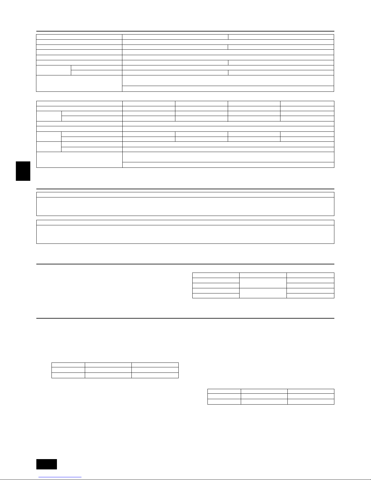
24
GB
D
F
INL
E
PGRRUTR
5. Vorgeschriebener Freiraum um das Aggregat
[Fig. 5.0.1] (P.2)
<A> Ansicht von oben <B> Seitenansicht
<C> Wenn bis zu einem Hindernis nur wenig Platz vorhanden ist
A Frontseite
B Keine Beschränkung der Wandhöhe (links und rechts)
C Luftauslaßbereich (Vor Ort beschafft)
D Muß offen sein E Wandhöhe (H)
L1 L2
PUHN-P-YEM-A 450 250
PUHY-P-YEM-A 450 450
(1) Grundlegender Platzbedarf
Für den Lufteinlaß ist an der Rückseite ein Freiraum von wenigstens 250 mm
notwendig. Für Bedienungs- und Wartungsarbeiten etc. von der Rückseite ist ein
Freiraum von 450 mm vorzusehen. Gleiches gilt für die Vorderseite.
(2) Wenn sich oberhalb der Anlage ein Hindernis befindet
(3) Wenn Einlaßluft von der rechten und linken Seite des Aggregats eintritt
• Die Wandhöhe (H) an der Front- und Rückseite sollte der Höhe der Klimaanla-
ge entsprechen.
• Wenn die Gesamthöhe überschritten wird, L
1 und L2 die “h”-Dimension in Fig.
5.0.1 hinzufügen.
(4) Wenn die Klimaanlage von Wänden umgeben ist
Hinweis:
• Die Wandhöhe (H) an der Front- und Rückseite sollte der Höhe der Klima-
anlage entsprechen.
• Wenn die Höhe der Platte überschritten wird, L
1 und L2 die “h”-Dimensi-
on in Fig. 5.0.1 hinzufügen.
L
1 L2
PUHN-P-YEM-A 450 250
PUHY-P-YEM-A 450 450
Beispiel: Wenn h = 100,
ergibt sich ein Maß L
1 von 450 + 100 = 550 mm.
Super Y
Modell
Geräuschpegel (50 / 60 Hz)
Nettogewicht
Anlage mit konstanter Kapazität
Anlage mit variabler Kapazität
Zulässiger Druck
Statischer Außendruck
Kältemittel
Anlage mit konstanter Kapazität
Anlage mit variabler Kapazität
Innenanlagen
Gesamtkapazität
Modell / Menge
Betriebstemperatur
PUHY-P600YSEM-A PUHY-P650YSEM-A PUHY-P700YSEM-A PUHY-P750YSEM-A
61,5 / 62,0 dB <A> 62,0 / 62,5 dB <A> 61,5 / 62,0 dB <A> 62,0 / 62,5 dB <A>
248 kg 263 kg 248 kg 263 kg
440 kg 440 kg 475 kg 475 kg
HD: 2,94 MPa, ND: 1,6 MPa
0 MPa
R407C: 6,5 kg R407C: 8,5 kg R407C: 6,5 kg R407C: 8,5 kg
R407C: 16 kg R407C: 16 kg R407C: 21 kg R407C: 21 kg
50 ~ 130 %
20 ~ 250 / 2 ~ 32
Betriebsart Kühlen: – 5 °CDB ~ 43 °CDB
(10 °CDB ~ 43 °CDB mit dem Außenaggregat in der unteren Position oder für
ein Innenaggregat des Typs 20 oder 25; nur diese Typen funktionieren hier).
etriebsart Heizen: – 15 °CWB ~ 15,5 °CWB
(– 12 °CWB ~ 10 °CWB mit einem Innenaggregat vom Typ 20 oder 25; nur diese Typen funktionieren hier).
3. Überprüfung des Lieferumfangs
PUHY-P400/500YEM-A
1 Rohrmontagestück (ø62) × 1 2 Rohrmontagestück (ø53) × 1 3 Rohrmontagestück (ø46) × 1
4 Schneidschraube M4 × 4 5 Anschlußrohr × 1 (Anschlußrohr ist am Aggregat befestigt.)
6 Packung (ø29 (innen), ø39 (außen)) × 1 7 Befestigungsplatte für die Elektroleitung × 1
PUHN-P200/250YEM-A
1 Rohrmontagestück (ø40) × 1 2 Rohrmontagestück (ø33) × 1 3 Rohrmontagestück (ø27) × 1
4 Schneidschraube M4 × 4 5 Ölausgleichsrohr 1 × 1 6
Anschlußrohr × 1 (Anschlußrohr ist am Aggregat befestigt.)
7 Packung (ø23 (innen), ø35 (außen)) × 1 8 Dichtung × 2 9 Verteilerkit
4. Kombination mit Außenanlagen
Eine Super Y (PUHY-P600/650/700/750YSEM-A) entsteht, wenn eine Anlage mit
konstanter Kapazität (PUHN-P200/250YEM-A) mit dieser Anlage (PUHY-P400/
500YEM-A) kombiniert wird.
Wenn diese Anlagen kombiniert werden, sind die Befestigungsteile
99
99
9
(Verteilerkit) für die Anlage mit konstanter Kapazität (PUHN-P200/250YEMA) zu verwenden.
Für R407-Modelle
Super Y
Anlage mit variabler Kapazität
Anlage mit konstanter Kapazität
PUHY-P600YSEM-A PUHN-P200YEM-A
PUHY-P650YSEM-A
PUHY-P400YEM-A
PUHN-P250YEM-A
PUHY-P700YSEM-A PUHN-P200YEM-A
PUHY-P750YSEM-A
PUHY-P500YEM-A
PUHN-P250YEM-A
2. Kombination mit Innenaggregaten
Modell
Geräuschpegel (50 / 60 Hz)
Nettogewicht
Zulässiger Druck
Statischer Außendruck
Kältemittel
Innenanlagen
Gesamtkapazität
Modell / Menge
Betriebstemperatur
PUHY-P400YEM-A PUHY-P500YEM-A
60 / 61 dB <A>
440 kg 475 kg
HD: 2,94 MPa, ND: 1,6 MPa
0 MPa
R407C: 16 kg R407C: 21 kg
50 ~ 130 %
25 ~ 250 / 1 ~ 20 25 ~ 250 / 1 ~ 20
Betriebsart Kühlen: – 5 °CDB ~ 43 °CDB (10 °CDB ~ 43 °CDB mit dem Außenaggregat in der unteren Position
oder für ein Innenaggregat des Typs 25; nur dieser Typ funktioniert hier).
etriebsart Heizen: – 12 °CWB ~ 15,5 °CWB (
– 12 °CWB ~ 10 °CWB mit einem Innenaggregat vom Typ 25; nur dieser Typ funktioniert hier).

25
GB
D
F
INL
E
PGRRUTR
6. Hebemethode
[Fig. 6.0.1] (P.2)
Vorsicht:
Beim Transport dieses Produkts sehr vorsichtig vorgehen.
- Keine Lasten über 20 kg allein tragen.
- Einige Produkte sind eventuell mit PP-Bändern verschnürt. PP-Bänder sind gefährlich und sollten nicht für den Transport eines Produkts verwendet werden.
- Darauf achten, die Kühlrippen des Wärmetauschers nicht mit den bloßen Händen zu berühren. Eine falsche Handhabung kann Schnitte in den Händen verursachen.
- Plastikverpackungsbeutel nach Auspacken zerreißen und entsorgen, damit diese nicht in die Hände von Kindern gelangen. Ein Kind kann ersticken, wenn es sich den
Plastikbeutel über den Kopf stülpt.
- Das Außenaggregat an vier Punkten aufgehängt tragen. Eine 3-Punkt-Aufhängung ist zum Anheben und Tragen des Aggregats nicht ausreichend und kann dazu führen,
daß das Aggregat fällt.
7. Einbau der Klimaanlage
7.1. Einbau
[Fig. 7.1.1] (P.2)
A Vor Ort beschaffter Ankerbolzen M10. B Ecke hat keinen Sitz.
• Die Anlage fest mit Schrauben anziehen, so daß die Anlage durch Erdbeben
oder heftige Windstöße nicht gelöst werden und herunterfallen kann.
• Für das Gerätefundament Betonstützen oder Stützwinkel verwenden.
• Je nach Installationsbedingungen können im Aufstellbereich Schwingungen
entstehen sowie Geräusche und Schwingungen an Boden und Wänden erzeugt werden. Daher reichlich Vibrationsschutz (Polstermaterial etc.) vorsehen.
• Dafür sorgen, daß die Ecken einen festen Sitz haben. Wenn dies nicht der Fall
ist, können sich die Befestigungsfüße verbiegen.
Warnung:
• Die für den Einbau gewählte Aufstellfläche muß dem Gewicht des Aggre-
gats mühelos standhalten.
Eine nicht ausreichend stabile Standfläche kann dazu führen, daß das
Aggregat umfällt und Personen verletzt.
• Das Aggregat wie in der Anleitung beschrieben einbauen, um Schäden
durch starken Wind oder Erdebenerschütterungen zu vermeiden.
Fehler beim Einbau können dazu führen, daß das Aggregat umfällt und
Unfälle mit Personenverletzungen verursacht.
Beim Legen des Fundamentes sorgfältig darauf achten, daß der Boden stark genug ausgelegt wird, daß während des Betriebs genügend Wasser zur Verfügung
steht, daß Wasser aus der Anlage abfließen kann und daß Platz für Rohr- und
Elektroleitungen vorhanden ist.
Vorkehrungen beim Verlegen von Rohr- und Elektroleitungen nach unten
Beim Verlegen von Rohr- und Elektroleitungen nach unten darauf achten, daß
Fundamente und Vorrichtungen am Boden die Öffnungen am Boden der Anlage
nicht verdecken. Bei Durchführung der Abwärtsrohrleitungen die Fundamente
wenigstens 150 mm hoch auslegen, damit die Rohrleitung unter der Anlage durchgeführt werden kann.
[Fig. 7.1.2] (P.3)
A Durchgangsöffnung der unteren Rohrleitung
B (Bolzenöffnung) C (Bolzenöffnung für ältere Modelle)
D Verdrahtung am Boden durch die Öffnung.
7.2. Anschlußrichtung für Kältemittelleitung
[Fig. 7.2.1] (P.3)
A Ausschnittloch B Bodenverlegung
C Frontseitenverlegung
D Verbindunprohrleitung (Aus Anlage mit konstantes Kapazität)
(Super Y-Gehäuse)
8. Installation der Kältemittelleitungen
Die Installation der Rohrleitungen erfolgt nach dem Zentralverteilungssystem. Hierbei werden die Kältemittelrohre vom Außenaggregat zum Zentralverteiler verlegt
und dann an jedes der einzelnen Innenaggregate verteilt.
Diese Methode des Anschlusses besteht aus sich verzweigenden Verbindungen
an die einzelnen Innenaggregate, Flanschanschlüsse der Rohre vom Außenaggregat und Anschlußverteilungen für die Flüssigkeitsrohre. Beachten Sie, daß
die Anschlüsse der Verteilungen hartgelötet sind.
Warnung:
Stets mit äußerster Sorgfalt darauf bedacht sein zu verhindern, daß bei Arbeiten mit Feuer oder offenen Flammen kein Kältemittelgas (R407C) austreten kann. Wenn das Kältemittelgas mit Flammen gleich welcher Art, wie etwa
aus Gasöfen, in Berührung kommt, zersetzt es sich und erzeugt ein Gas, das
Vergiftungen hervorrufen kann. Niemals in einem unbelüfteten Raum
Schweißarbeiten ausführen. Nach Abschluß der Installationsarbeiten an
Kältemittelrohrleitungen stets eine Inspektion vornehmen.
8.1. Vorsicht
1 Verwenden Sie für die Kältemittelrohre folgende Materialien.
• Material: Kältemittelrohrleitungen müssen aus Phosphor-desoxidiertem
Kupfer bestehen. Darüber hinaus dafür sorgen, daß die Innen- und Außenflächen der Rohre sauber sind und keine gefährlichen Schwefeloxyde, keinen Staub/Schmutz, keine Bearbeitungsrückstände, Öle, Feuchtigkeit oder
sonstige Verunreinigungen aufweisen. (Für Modelle R407C)
2 Normal verkäufliche Rohre enthalten oft Staub und anderes Material. Blasen
Sie die Rohre immer mit trockener Druckluft sauber.
3 Tragen Sie dafür Sorge, daß kein Staub, Wasser oder andere Verunreinigun-
gen während der Installation in die Rohrleitungen gelangen können.
4 Biegungen in der Leitung sind so weit wie möglich zu vermeiden. Bei notwen-
dige Biegungen sollte der Biegeradius so groß wie möglich sein.
5 Beachten Sie immer die Einschränkungen der Kältemittelrohre (wie z.B. der
vorgegebenen Länge, den Unterschied zwischen hohem / niedrigem Druck
und dem Durchmesser des Rohres). Werden diese Vorgaben nicht beachtet,
ist ein Fehler beim Betrieb der Geräte oder ein Abfall der Heiz- / Kühlleistung
möglich.
6 Das Aggregat der City Multi Y Serie stoppt, wenn unnormale Zustände, wie zu
hohe oder nicht genügende Kühlung, vorliegen. Füllen Sie bei einem solchen
Zustand das Gerät entsprechend der Vorschriften. Lassen Sie eine Wartung
durchführen, prüfen Sie immer die Hinweise, die sich auf die Länge der Rohre
und die Gesamtzahl der Kühlgeräte an beiden Orten, beziehen. Beachten Sie
dabei die Tabelle der Kalkulation der Kühlflüssigkeit auf der Rückseite des
Servicefeldes und die zusätzlichen Kühleinheiten auf den Aufklebern für die
kombinierte Anzahl der Innenaggregate.
7 Zur Füllung des Systems flüssiges Kältemittel verwenden.
8 Benutzen Sie niemals ein Kältemittel, um eine Reinigung der Luft durchzufüh-
ren. Benutzen Sie zum Absaugen immer eine Absaugpumpe.
(5) Einbau mehrerer Klimaanlagen und fortlaufender Einbau
• Für die Gesamtinstallation und die fortlaufende Installation erforderlicher Frei-
raum:
Beim Installieren mehrerer Anlagen zwischen jedem Block, wie nachstehend
dargestellt, Freiraum für den Durchgang von Personen und für die Luftzirkulation
einräumen.
• In zwei Richtungen offen.
• Falls die Wandhöhe die Gesamthöhe der Klimaanlage überschreitet, ist in der
folgenden Tabelle die oben gezeigte Dimension “h” (h = Wandhöhe <H> –
Gesamthöhe der Klimaanlage) zu der mit * markierten Dimension hinzuzufügen.
• Wenn sich sowohl an der Vorder- als an der Rückseite des Gerätes eine Wand
befindet, bis zu drei Geräte nacheinander in seitlicher Richtung installieren
und für jedes der drei Geräte einen Freiraum von 1000 mm oder mehr als
Zugangs-/Durchgangsraum vorsehen.

26
GB
D
F
INL
E
PGRRUTR
9 Isolieren Sie die Rohrleitung immer einwandfrei. Nicht ausreichende Isolation
kann als Folge ein Nachlassen der Heiz- / Kühlleistung, Kondensieren von
Wassertropfen oder ähnliche Probleme bewirken.
0 Wenn Sie die Kältemittelrohre anschließen, stellen Sie sicher, daß der Kugel-
hahn des Außenaggregats vollständig geschlossen ist (die Werkseinstellung).
Betreiben Sie die Einheit nicht, bevor die Kältemittelrohre an das Außenaggregat
und an die Innenaggregate vollständig angeschlossen sind, ein Kältemittel-
lecktest durchgeführt wurde und die Luft komplett abgepumpt ist.
A Benutzen Sie zum Hartlöten der Rohre immer nicht oxydierendes Material.
Verwenden Sie oxydierendes Material, können Verstopfungen die Folge sein
oder die Kompressoreinheit beschädigt werden.
B Niemals bei Regen Rohrleitungsanschlußarbeiten an der Außenanlage
durchführen.
Warnung:
Beim Installieren und Verlegen der Anlage kein anderes Kältemittel als das
auf der Anlage angegebene Kältemittel (R407C) einfüllen.
- Vermischung mit einem anderen Kältemittel, mit Luft etc. kann zu Fehlfunktionen des Kältemittelkreislaufs und zu schweren Schäden an der Anlage füh-
ren.
Vorsicht:
• Eine Vakuumpumpe mit einem Reverse Flow (Gegenstrom) - Rückschlag-
ventil verwenden. (Für Modelle R407C)
- Wenn die Vakuumpumpe kein Gegenstromrückschlagventil hat, kann das Öl
der Vakuumpumpe in den Kältemittelkreislauf zurückfließen und eine Qualitätsminderung des Kältemaschinenöls und andere Störungen verursachen.
• Die bei herkömmlichen Kältemitteln eingesetzten, nachstehend dargestellten, Hilfsvorrichtungen nicht verwenden. (Für Modelle R407C)
(Meßrohrleitung, Füllschlauch, Gasaustrittsfühler, Rückschlagventil, Kältemittel-Base, Vakuummeter, Kältemittelauffangvorrichtung)
- Vermischen von herkömmlichem Kältemittel und Kältemaschinenöl kann zur
Qualitätsminderung des Kältemaschinenöls führen.
- Vermischen mit Wasser führt zur Qualitätsminderung des Kältemaschinen-
öls.
-Kältemittel R407C enthält kein Chlor. Daher reagieren Gasaustrittsfühler für
herkömmliche Kältemittel nicht darauf.
• Hilfsorrichtungen sorgfältiger handhaben als üblich. (Für Modelle R407C)
- Wenn Staub, Schmutz oder Wasser in den Kältemittelkreislauf gelangt, wird
die Qualität des Kältemaschinenöls gemindert.
• Niemals vorhandene Kältemittelrohrleitungen einsetzen. (Für Modelle
R407C)
- Die große Menge Chlor in herkömmlichen Kältemitteln und Kältemaschinenöl
in der vorhandenen Rohrleitung führt zu einer Qualitätsminderung des neu-
en Kältemittels.
• Die zu verwendende Rohrleitung während der Installation in einem geschlossenen Raum aufbewahren und beide Enden der Rohrleitung bis
unmittelbar vor dem Hartlöten abgedichtet lassen.
- Wenn Staub, Schmutz oder Wasser in den Kältemittelkreislauf gelangen,
wird die Qualität des Öls gemindert, was zum Ausfall des Kompressors füh-
ren kann.
• Keinen Füllzylinder verwenden. (Für Modelle R407C)
- Bei Verwendung eines Füllzylinders kann das Kältemittel verderben.
• Zum Auswaschen der Rohrleitung keine Spezialwaschmittel verwenden.
8.2. Das Kältemittel Rohrsystem
Å Flüssigkeitsrohr ı Gasrohr
Ç Gesamtkapazität der Innenaggregate Î Modellnummer
‰ Gesamtaggregate in Flußrichtung Ï Modell Verteilungskit
Ì 4 fache Kopfverteilung Ó 7 fache Kopfverteilung
¬ 10 fache Kopfverteilung
Anschlußbeispiele (PUHY-P400/500YEM-A)
[Fig.8.2.1] (P.3)
A Außenaggregat
B Erste Abzweigung
Die erste Abzweigung an der Außenanlage muß die CMY-Y202-F sein.
C Innenaggregat D Aggregate in Flußrichtung
Hinweis:
• Das Gesamtmodell der Aggregate in Flußrichtung, das in der nächsten
Tabelle gezeigt wird, entspricht dem Gesamtmodell in der Zeichnung,
wenn Sie sie von Punkt A aus betrachten.
[Fig.8.2.2] (P.3)
A Außenaggregat
B Erste Abzweigung (Abzweigungsverbindung)
Die erste Abzweigung muß die CMY-Y202-F sein, wenn die Außenanlage und
die Kopfabzweigung verwendet werden.
C Verbindung der Verteilung D Innenaggregat
E Kopfverteilung F Abschlußkappe
Hinweis:
• Rohrleitungsabzweige können nach dem Kopfabzweig nicht wiederverwendet werden.
• Das Gesamtmodell der Aggregate in Flußrichtung, das in der nächsten
Tabelle gezeigt wird, entspricht dem Gesamtmodell in der Zeichnung,
wenn Sie sie von Punkt A aus betrachten.
Anschlußbeispiele (PUHY-P600/650/700/750YSEM-A)
[Fig.8.2.3] (P.4)
A Anlage mit konstanter Kapazität B Anlage mit variabler Kapazität
C Erste Verteilung D Innenaggregat
E Zu den abwärts angeordneten Anlagen
F Verteiler (Flüssigkeit), Verteiler (Gas) → Hinweis 2
G ÖlausgleIichsrohr (sonderzubehör)(für Verteilung innerhalb der Anlage)
H Verteiler (Gas)(sonderzubehör)
I Verteiler (Flüssigkeit) (sonderzubehör) J Gasleitung A
K Flüssigkeitsleitung A L Gasleitung B
M Flüssigkeitsleitung B N Gasleitung (Hauptleitung) C
O Flüssigkeitsleitung (Hauptleitung) C
P Zeigt die Rohrleitungsanschlußpunkte an
Hinweis 1:
• Das Gesamtmodell der Aggregate in Flußrichtung, das in der nächsten
Tabelle gezeigt wird, entspricht dem Gesamtmodell in der Zeichnung,
wenn Sie sie von Punkt A aus betrachten.
• Mit Ausnahme von PUHY-P600YSEM-A ist die erste Abzweigung stets
CMY-Y302-F.
Hinweis 2:
• Weil es in die Anlage mit variabler Kapazität eingebaut ist, dient B nur
zur Beförderung von Flüssigkeit. Die Anlage mit konstanter Kapazität
und die Anlage mit variabler Kapazität gemäß der in der Abbildung oben
angegebenen Abmessung G einstellen(G = 0,01 m).
Hinweis 3:
• Das Verteilerkit wird an der Anlage mit konstanter Kapazität befestigt.
[Fig.8.2.4] (P.4)
A Anlage mit konstanter Kapazität B Anlage mit variabler Kapazität
C Erste Verteilung (Abzweigungsverbindung)
D Abzweigungsverbindung E Innenaggregat
F Kopfverteilung G Abschlußkappe
H Verteiler (Flüssigkeit), Verteiler (Gas) → Hinweis 2
Hinweis 1:
• Das Gesamtmodell der Aggregate in Flußrichtung, das in der nächsten
Tabelle gezeigt wird, entspricht dem Gesamtmodell in der Zeichnung,
wenn Sie sie von Punkt A aus betrachten.
• Mit Ausnahme von PUHY-P600YSEM-A ist die erste Abzweigung stets
CMY-Y302-F.
Hinweis 2:
• Weil es in die Anlage mit variabler Kapazität eingebaut ist, dient B nur
zur Beförderung von Flüssigkeit. Die Anlage mit konstanter Kapazität
und die Anlage mit variabler Kapazität gemäß der in der Abbildung oben
angegebenen Abmessung G einstellen (G = 0,01 m).
Hinweis 3:
• Das Verteilerkit wird an der Anlage mit konstanter Kapazität befestigt.
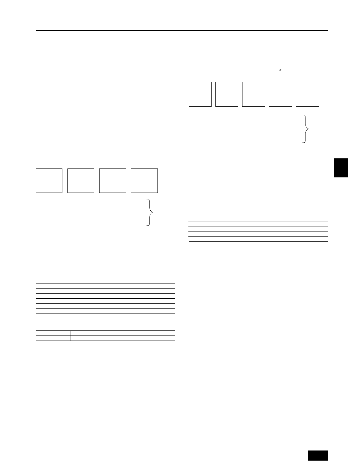
27
GB
D
F
INL
E
PGRRUTR
• Wenn die Berechnung eine Bruchzahl von weniger als 0,1 kg ergibt, diesen
Wert auf den nächsten von 0,1 kg aufrunden. Wenn z.B. das Ergebnis der
Berechnung 20,03 kg für kg beträgt, das Ergebnis auf 20,1 kg aufrunden.
• Wenn die Gesamtmenge des Kältemittels einschließlich der Menge Kältemittel, das bei Versand ab Werk in der Außenanlage versiegelt ist plus zusätzlichem Kältemittel für die Rohrleitungsverlängerung 73 kg überschreitet,
73 kg als Gesamtkältemittelmenge verwenden. Menge des Kältemittels bei
Versand ab Werk + hinzugefügtem Kältemittel
=
73 kg.
<Zusätzliche Kältemittelmenge>
++ ++ +
α
<Beispiele>
Innenbereich 1: 125 A: ø12,7 3 m a: ø9,52 10 m
2: 125 B: ø15,88 1 m b: ø9,52 5 m
3: 125 C: ø19,05 30 m c: ø9,52 5 m
4: 125 D: ø15,88 10 m d: ø9,52 10 m
5: 100 E: ø12,7 5 m e: ø9,52 15 m
6: 40 F: ø12,7 15 m f: ø6,35 5 m
Die Gesamtlänge jedes Flüssigkeitsrohres sehen Sie nachfolgend:
ø19,05: C = 30 m
ø15,88: B + D = 1 + 10 = 11 m
ø12,7: A + E + F = 3 + 5 + 15 = 23 m
ø9,52: a + b + c + d + e = 10 + 5 + 5 + 10 + 15 = 45 m
ø6,35: f = 5 m
Deshalb,
<Kalkulationsbeispiel>
Zusätzlich einzufüllende
Kältemittelmenge = 30 × 0,29 + 11 × 0,25 + 23 × 0,12 +
45 × 0,06 + 5 × 0,024 + 3,0 = 20,1 kg
Wert von α
Gesamtzahl der Innenaggregate α
Bis zu 80 Geräte 1,0 kg
Von 81 bis 160 Geräte 1,5 kg
Von 161 bis 330 Geräte 2,0 kg
Von 331 bis 480 Geräte 2,5 kg
Modelle 481 oder höher 3,0 kg
9.2. Vorsichtsmaßregeln für Rohranschluß/
Ventilbetrieb
[PUHY-P400/500YEM-A]
• Rohrleitungsanschluß und Armaturbetrieb genauestens ausführen.
• Das Anschlußrohr auf der Gasseite wurde vor dem Transport werksseitig zu-
sammengebaut.
1 Zum Hartlöten des Anschlußrohrs mit Flansch das Rohr vom Schwimmer-
ventil trennen und außerhalb des Aggregats verlöten.
2 Beim Trennen des Flanschanschlußrohrs die an der Rückseite dieses Blat-
tes befestigte Dichtung entfernen und auf die Flanschoberfläche des
Schwimmerventils kleben, um zu vermeiden, daß Staub in das Ventil gelangt.
3 Der Kältemittelumlauf ist werksseitig mit einer runden, dichtgepackten
Packung abgedichtet, um das Austreten von Gas zwischen den Flanschen
zu verhindern. Da ein Betrieb in diesem Zustand nicht möglich ist, muß die
Packung durch eine Hohlpackung am Rohranschluß ausgetauscht werden.
4 Vor dem Anbringen der Hohlpackung jeglichen Staub auf der Flansch-
oberfläche und der Packung abwischen und beide Seiten der Packung mit
Kühlaggregatöl (R407C: Esteröl, Ätheröl oder Alkylbenzole [kleine Menge]) bestreichen.
[Fig. 9.2.1] (P.4)
A Straff anliegende Verpackung B Hohlpackung
• Nach dem Entleeren und Einfüllen des Kältemittels stellen Sie sicher, daß der
Hebel des Ventils voll geöffnet ist. Sollten Sie die Anlage mit geschlossenem
Ventil betrieben, kann das zu übermäßig hohem Druck auf der Hochdruck-
seite oder der Niederdruckseite deKältemittelelkreislaufes führen, wodurch der
Kompressor oder das 4 - Wege Ventil usw. beschädigt werden können.
Größe des
Flüssigkeitsrohres
Gesamtlänge von
ø15,88 × 0,25
(m) × 0,25 (kg/m)
Größe des
Flüssigkeitsrohres
Gesamtlänge von
ø12,7 × 0,12
(m) × 0,12 (kg/m)
Größe des
Flüssigkeitsrohres
Gesamtlänge von
ø9,52 × 0,06
(m) × 0,06 (kg/m)
Größe des
Flüssigkeitsrohres
Gesamtlänge von
ø6,35
×
0,024
(m) × 0,024 (kg/m)
Größe des
Flüssigkeitsrohres
Gesamtlänge von
ø19,05 × 0,29
(m) × 0,29 (kg/m)
Bei den
unten
aufgeführten
Konditionen:
Die Gesamtlänge jedes Flüssigkeitsrohres sehen Sie nachfolgend:
ø15,88: A = 30 m
ø12,7: B + C = 10 + 15 = 25 m
ø9,52: a + b = 10 + 20 = 30 m
ø6,35: c + d + e = 10 + 10 + 10 = 30 m
Deshalb,
<Kalkulationsbeispiel>
Zusätzlich einzufüllende
Kältemittelmenge = 30 × 0,25 + 25 × 0,12 + 30 × 0,06 + 30 × 0,024 + 2,0 = 15,1 kg
Wert von α
Gesamtzahl der Innenaggregate α
Bis zu 80 Geräte 1,0 kg
Von 81 bis 160 Geräte 1,5 kg
Von 161 bis 330 Geräte 2,0 kg
Von 331 bis 480 Geräte 2,5 kg
Modelle 481 oder höher 3,0 kg
[PUHY-P600/650/700/750YSEM-A]
(kg)
Anlage mit variabler Kapazität Anlage mit konstanter Kapazität
P400 P500 P200 P250
16 21 6,5 8,5
• Zusätzliches Kältemittel einfüllen
Bei Versand ab Werk ist die Außenanlage mit Kältemittel gemäß obiger Tabelle
gefüllt. In dieser Menge des Kältemittels sind die weiteren Mengen nicht enthalten,
die je nach Länge der Rohrleitungen notwendig sind. Es muß daher eine weitere
Menge Kältemittel für jede weitere Kältemittellinie in die Anlage eingefüllt werden.
Im Hinblick auf die Durchführung weiterer Wartungsarbeiten zu einem späteren
Zeitpunkt, stellen Sie sich eine Liste der Größe und Länge jeder Kältemittelleitung
und der Menge des zusätzlichen eingefüllten Kältemittels zusammen. Einen Entwurf der Liste und die entsprechenden Spalten zum Ausfüllen finden Sie im Außenaggregat.
• Kalkulation des zusätzlichen Kältemittels
• Kalkulieren Sie die Menge des zusätzlich einzufüllenden Kältemittels auf
der Basis der Länge des Rohrnetzes für das Kältemittel und dessen Durchmesser.
• Benutzen Sie die rechts stehende Tabelle dafür, um die Menge des zusätz-
lich einzufüllenden Kältemittels zu errechnen, und füllen Sie diese errechnete Menge in die Anlage.
9. Zusätzliches Kühlmittel einfüllen
9.1. Kalkulation des zusätzlichen Kühlmittels
[PUHY-P400/500YEM-A]
• Zusätzliches Kältemittel einfüllen
Zum Zeitpunkt des Versandes ist die Außenanlage PUHY-P400 mit 16 Kg und das
Modell PUHY-P500 mit 21 Kg Kältemittel gefüllt. In dieser Menge des Kältemittels
sind die weiteren Mengen nicht enthalten, die je nach Länge der Rohrleitungen notwendig sind. Es muß daher eine weitere Menge Kältemittel für jede weitere
Kältemittellinie in die Anlage eingefüllt werden. Im Hinblick auf die Durchführung
weiterer Wartungsarbeiten zu einem späteren Zeitpunkt, stellen Sie sich eine Liste
der Größe und Länge jeder Kältemittelleitung und der Menge des zusätzlichen eingefüllten Kältemittels zusammen. Einen Entwurf der Liste und die entsprechenden
Spalten zum Ausfüllen finden Sie im Außenaggregat.
• Kalkulation des zusätzlichen Kältemittels
• Kalkulieren Sie die Menge des zusätzlich einzufüllenden Kältemittels auf
der Basis der Länge des Rohrnetzes für das Kältemittel und dessen Durchmesser.
• Benutzen Sie die rechts stehende Tabelle dafür, um die Menge des zusätz-
lich einzufüllenden Kältemittels zu errechnen, und füllen Sie diese errechnete Menge in die Anlage.
• Wenn das Ergebnis der Berechnung einen Bruch von weniger als 0,1 kg
ausmacht, auf die nächsten 0,1 kg aufrunden. Wenn das Ergebnis der Berechnung beispielsweise 15,02 lautet, die Menge auf 15,1 aufrunden.
<Zusätzliche Kältemittelmenge>
++ + +
α
<Beispiele>
Innenbereich 1: 125 A: ø15,88 30 m a: ø9,52 10 m
2: 100 B: ø12,7 10 m b: ø9,52 20 m
3: 40 C: ø12,7 15 m c: ø6,35 10 m
4: 32 d: ø6,35 10 m
5: 32 e: ø6,35 10 m
Bei den
unten
aufgeführten
Konditionen:
Größe des
Flüssigkeitsrohres
Gesamtlänge von
ø15,88 × 0,25
(m) × 0,25 (kg/m)
Größe des
Flüssigkeitsrohres
Gesamtlänge von
ø12,7 × 0,12
(m) × 0,12 (kg/m)
Größe des
Flüssigkeitsrohres
Gesamtlänge von
ø9,52 × 0,06
(m) × 0,06 (kg/m)
Größe des
Flüssigkeitsrohres
Gesamtlänge von
ø6,35 × 0,024
(m) × 0,024 (kg/m)

28
GB
D
F
INL
E
PGRRUTR
• Die zusätzliche Kältemitteleinfüllmenge mit Hilfe der erwähnten Rechenformel
bestimmen und das Kältemittel nach Anschluß aller Rohrleitungen durch die
Wartungsöffnung einfüllen.
• Nach Abschluß aller Arbeiten die Wartungsöffnung fest schließen und mit dem
Deckel abdecken, um das Austreten von Gas zu vermeiden.
[Fig. 9.2.2] (P.4)
<A> [Kugelarmatur (flüssigkeitsseite)]
<B> [Kugelarmatur (gasseite)]
<C> (Diese Abbildung zeigt die Armatur in vollständig geöffnetem Zustand.)
A Armaturspindel
[Ab Werk vollständig geschlossen, beim Anschluß der Rohrleitung, beim
Auspumpen und beim Einfüllen von zusätzlichem Kältemittel vollständig
schließen. Nach Abschluß obengenannter Vorgänge vollständig öffnen.]
B Arretierstift [Verhindert, daß sich die Armaturspindel um 90° oder mehr
dreht.]
C Packung (sonderzubehör)
D Anschlußrohr (sonderzubehör)
[Mit der Packung dieses Rohr fest am Armaturflansch anbringen, damit
kein Gasaustritt erfolgt.(Anzugsdrehmoment: 43 N·m (430 kg·cm)) Beide
Flächen der Packung mit Kältemaschinenöl (R407C: Esteröl, Etheröl oder
Alkylbenzole [kleine Menge]) bestreichen.
E Öffnen (Langsam laufen lassen)
F Deckel, Kupferpackung
[Den Deckel abnehmen und die Armaturspindel betätigen. Den Deckel nach
Abschluß des Vorgangs stets wieder anbringen. (Anzugsdrehmoment für
Armaturspindeldeckel: 25 N·m (250 kg·cm) oder mehr)]
G Wartungseinheit
[Mit dieser Wartungseinheit die Kältemittelrohrleitung auspumpen und für
eine zusätzliche Füllung vor Ort verwenden.
Wartungseinheit mit einem doppelseitigen Schraubenschlüssel öffnen und
schließen.
Nach Abschluß des Vorgangs Deckel stets wieder anbringen. (Anzugsdrehmoment für den Deckel der Wartungseinheit: 14 N·m (140 kg·cm) oder
mehr)]
H Konusmutter
[Anzugsdrehmoment: 80 N·m (800 kg·cm)
Diese Mutter mit einem doppelseitigen Schraubenschlüssel lockern.
Die Oberfläche der Aufweitung mit Kältemaschinenöl.]
I ø15,88
J ø34,93
K Hausrohrleitung
[An das Anschlußrohr mittels Hartlöten anschließen. (Mit sauerstofflosem
Hartlötverfahren löten.)]
[PUHY-P600/650/700/750YSEM-A]
<Für Anlage mit variabler Kapazität>
• Rohrleitungsanschluß und Armaturbetrieb genauestens ausführen.
• Nach Vornahme des nachstehenden Ver teileranschlusses (Gas), das Anschluß-
rohr der Anlage mit variabler Kapazität, das zum Gaskugelventil gehört, ab-
nehmen und den Verteiler (Gas) (sonderzubehör) anbringen.
1 Beim Hartlöten des Verteilers (Gas) den Hartlötvorgang vor Montage der
Anlage mit variabler Kapazität außerhalb der Anlage vornehmen.
2 Während der Zeit, in der das Anschlußrohr mit Flansch abgenommen ist,
die an der Rückseite dieses Blechs angebrachte Dichtung abnehmen und
sie an der Flanschfläche des Kugelventils anheften, um das Eindringen
von Schmutz in das Ventil zu verhindern.
3 Der Kältemittelumlauf ist werksseitig mit einer runden, dichtgepackten
Packung abgedichtet, um das Austreten von Gas zwischen den Flanschen
zu verhindern. Da ein Betrieb in diesem Stadium nicht möglich ist, muß die
Packung gegen die hohlen Packung am Rohranschluß ausgetauscht werden.
4 Vor dem Anbringen der Hohlpackung jeglichen Staub auf der Flansch-
oberfläche und der Packung abwischen und beide Seiten der Packung mit
Kühlaggregatöl (R407C: Esteröl, Ätheröl oder Alkylbenzole [kleine Menge]) bestreichen.
[Fig. 9.2.3] (P.5)
<A> [Bei Versand ab Hersteller]
<B> [Nach Installation]
A Straff anliegende Verpackung B Hohlpackung
• Nach Entlüftung und Befüllung mit Kältemittel darauf achten, daß der Handgriff vollständig geöffnet ist. Bei Betrieb mit geschlossener Armatur wird abnormaler Druck auf die Hoch- oder Niedrigdruckseite des Kältemittelkreislaufs
ausgeübt oder es entsteht aufgrund fehlenden Öldurchflusses zwischen den
Anlagen ein Ölengpaß im Kompressor. Dies kann zu Schäden am Kompressor, der Vier-Wege-Armatur etc. führen.
•
Zum Entlüften dafür sorgen, daß zwischen den Anlagen mit variabler Kapazität und mit konstanter Kapazität ein Ölausgleichsrohr angebracht wird.
• Die zusätzliche Kältemitteleinfüllmenge mit Hilfe der erwähnten Rechenformel
bestimmen und das Kältemittel nach Anschluß aller Rohrleitungen durch die
Wartungsöffnung einfüllen.
• Nach Abschluß der Arbeiten die Wartungseinheit und die Kappe dicht verschließen, damit kein Gas austreten kann.
• Die Kugelventilrohrleitung in der Reihenfolge (Ölausgleich) → (Flüssigkeits-
seite) → (Gasseite) anschließen.
[Fig. 9.2.4] (P.5)
<A> [Kugelarmatur (Flüssigkeitsseite)]
<B> [Kugelarmatur (Gasseite)]
<C> [Kugelventil (Ölausgleichsseite)]
<D> (Diese Abbildung zeigt die Armatur in vollständig geöffnetem Zustand.)
A Armaturspindel
[Ab Werk vollständig geschlossen, beim Anschluß der Rohrleitung, beim Aus-
pumpen und beim Einfüllen von zusätzlichem Kältemittel vollständig schließen. Nach Abschluß obengenannter Vorgänge vollständig öffnen.]
B Arretierstift [Verhindert, daß sich die Armaturspindel um 90° oder mehr dreht].
C Packung [sonderzubehör]
D Verteiler (Gas) (sonderzubehör)
[Die Packung (sonderzubehör) fest am Ventilflansch montieren, so daß kein
Gas austritt. (Anzugsdrehmoment für die Schraube beträgt 43 N·m (430 kg·cm).)
Beide Flächen der Packung mit Kältemaschinenöl (R407C: Esteröl, Etheröl
oder Alkylbenzole [kleine Menge]) bestreichen.
E Öffnen (Langsam laufen lassen)
F Deckel, Kupferpackung
[Den Deckel abnehmen und die Armaturspindel betätigen. Den Deckel nach
Abschluß des Vorgangs stets wieder anbringen. (Anzugsdrehmoment für
Armaturspindeldeckel: 25 N·m (250 kg·cm) oder mehr)]
G Wartungseinheit
[Mit dieser Wartungseinheit die Kältemittelrohrleitung auspumpen und für eine
zusätzliche Füllung vor Ort verwenden.
Wartungseinheit mit einem doppelseitigen Schraubenschlüssel öffnen und
schließen.
Nach Abschluß des Vorgangs Deckel stets wieder anbringen (Anzugsdrehmoment für den Deckel der Wartungseinheit: 14 N·m (140 kg·cm) oder
mehr)]
H Konusmutter
[Anzugsdrehmoment: 80 N·m (800 kg·cm) ... Flüssigkeit, 55 N·m (550 kg·cm)
... Ölausgleich. Die Mutter mit einem doppelseitigen Schraubenschlüssel lokkern und anziehen.
Die Kontaktflächen des Konusanschlusses mit Kältemaschinenöl (R407C:
Esteröl, Etheröl oder Alkylbenzole [kleine Menge]) auftragen.]
I ø34,93 (PUHY-P600YSEM-A)
ø41,28 (PUHY-P650/700/750YSEM-A)
J Hausrohrleitung
[An das Anschlußrohr mittels Hartlöten anschließen. (Mit sauerstofflosem
Hartlötverfahren löten).]
K ø15,88
L Zum Verteiler (Flüssigkeit)
M ø12,7
N Zur Anlage mit Konstanter Kapazität
O ø28,58
Warnung:
Vor der Montage des Verteilers (Gas) * am Kugelventil der Anlage mit variabler Kapazität, den Verteiler (Gas) außerhalb der Anlage hartlöten.
- Erfolgt das Hartlöten bei der Montage, wird das Kugelventil erhitzt. Dies kann zu
Rissen oder zum Austritt von Gas führen. Auch kann die Verdrahtung innerhalb
der Anlage verbrennen.
<Bei der Anlage mit konstanter Kapazität>
• Anschluß der Rohrleitung und Betrieb der Ventile genau wie in der nachstehenden Abbildung dargestellt vornehmen.
• Die Anschlußrohrleitung auf der Gasseite ist bei Versand der Einrichtung bereits zusammengebaut.
1 Beim Hartlöten des Flanschs an das Anschlußrohr, das Anschlußrohr mit
dem Flansch vom Kugelventil abnehmen und außerhalb der Anlage hartlöten.
2 Während der Zeit, in der das Anschlußrohr mit Flansch abgenommen ist,
die an der Rückseite dieses Blechs angebrachte Dichtung abnehmen und
sie an der Flanschfläche des Kugelventils anheften, um das Eindringen
von Schmutz in das Ventil zu verhindern.
3 Der Kältemittelumlauf ist werksseitig mit einer runden, dichtgepackten
Packung abgedichtet, um das Austreten von Gas zwischen den Flanschen
zu verhindern. Da ein Betrieb in diesem Stadium nicht möglich ist, muß die
Packung gegen die hohlen Packung am Rohranschluß ausgetauscht werden.
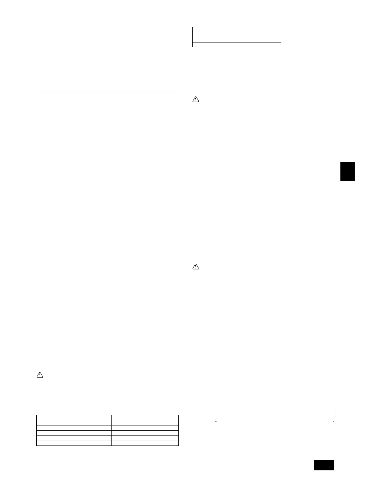
29
GB
D
F
INL
E
PGRRUTR
Standard-Befestigungswinkel:
Rohrdurchmesser (mm)
Anzugswinkel (°)
ø6,35, ø9,52 60 bis 90
ø12,7, ø15,88 30 bis 60
ø19,05 20 bis 35
[Fig. 9.2.7] (P.5)
Hinweis:
Wenn kein Drehmomentschlüssel vorhanden ist, folgendes Standardverfahren verwenden:
Wenn Sie die Konusmutter mit einem Schraubenschlüssel anziehen, kom-
men Sie an einenPunkt, an dem sich das Anzugsdrehmoment abrupt erhöht.
Die Konusmutter in dem in der Tabelle oben dargestellten Winkel über die-
sen Punkt hinaus anziehen.
Vorsicht:
• Das Anschlußrohr stets von der Kugelarmatur abnehmen und es außer-
halb der Anlage hartlöten.
- Hartlöten des Anschlußrohrs im installierten Zustand führt zum Erhitzen der
Kugelarmatur und zieht Störungen oder Gasaustritt nach sich. Auch kann
die Rohrleitung etc. innerhalb der Anlage Brandschäden erleiden.
• Zum beschichten der Konus- und Flanschanschlüsse Esteröl, Etheröl oder
Alkylbenzole (kleine Menge) als Kältemittelöl verwenden. (Für R407CModelle)
- Das Kältemaschinenöl zersetzt sich, wenn es mit größeren Mengen Mine-
ralöl vermischt wird.
• Keine Additive zur Erkennung von undichten Stellen verwenden.
9.3. Verfahren zum Anschluß des
Ölausgleichsrohres
• Die Ölausgleichsrohrleitung kann von der Vorderseite, der Unterseite oder der
Anlagenseite (linke Seite für die Anlage mit variabler Kapazität, rechte Seite
für die Anlage mit konstanter Kapazität) abgenommen werden.
• Rohrleitungsanschluß und Betrieb der Armaturen exakt gemäß nachstehender Beschreibung vornehmen (Einzelheiten dazu finden sich unter 9.2).
1 Nach Anschluß das Ölausgleichsrohres Entlüftung mit Hilfe der Wartungs-
einheit der Armatur auf der Seite der Anlage mit variabler Kapazität sicherstellen.
2 Nach Entlüftung dafür sorgen, daß die Spindel jeder Armatur vollständig
geöffnet ist. Wenn der Betrieb bei geschlossener Armatur erfolgt, kann ein
Ölengpaß im Kompressor durch fehlenden Ölfluß zwischen den Anlagen
auftreten, der zu Schäden am Kompressor führen kann.
3 Nach Abschluß der Arbeiten den Deckel der Wartungseinheit und den
Bereich des Handgriffs fest verschließen, damit kein Gas austreten kann.
Warnung:
Wird das Ölausgleichsrohr nicht angeschlossen, kann dies zu Schäden am
Kompressor führen.
• Zwischen den Anlagen mit variabler und konstanter Kapazität 10 mm Frei-
raum lassen. Die Anlage mit variabler Kapazität mit der Vorderseite nach rechts
und die mit konstanter Kapazität mit der Vorderseite nach links positionieren.
Das Ölausgleichsrohr für das Verteilerkit, das an der Anlage mit konstanter
Kapazität befestigt ist, gemäß nachstehendem Verfahren anschließen.
1 Die Löcher zum Ausbrechen auf der Platte links für die Anlage mit varia-
bler Kapazität und auf der rechten Seite für die Anlage mit konstanter Kapazität öffnen.
2 Nach Installation der Anlagen den Anschluß der Rohrleitung, die zur Anla-
ge gehört (ø 12,7), mittels Aufweitung vornehmen.
3 Den Freiraum zwischen den Anlagen mit den 2 Dichtungen, die zur Anla-
ge mit konstanter Kapazität gehören, blockieren.
4 Die Rohrabdeckung zwischen Ölausgleichsrohr 2 und Ölausgleichsrohr 3
(Sonderzubehör im Verteilerkit) auflegen.
[Fig. 9.3.1] (P.5)
<A> (Anlage mit konstanter Kapazität) <B> (Anlage mit variabler Kapazität)
<C> Kompressor <D> Schaltkasten
A 10 mm (Freiraum zwischen den Anlagen)
B Rechte Platte C Linke Platte
D Kugelventil (Ölausgleich) ø 12,7 (aufgeweitet)
E Ölausgleichsrohr 1 (sonderzubehör) F Ölausgleichsrohr 2 (sonderzubehör)
G Aufgeweiteter Anschluß
Anzugsdrehmoment beträgt 55 N·m (550 kg·cm).
Mit einem Doppelschraubenschlüssel öffnen und schließen. Auf beide Seiten der aufgeweiteten Kontaktfläche eine Schicht Kältemittelöl auftragen.
H Ölausgleichsrohr 3 (sonderzubehör)
I Dichtungsmaterial (2 Stücke, mitgeliefert)
J Durch die Öffnungen für Ölausgleichsrohr und Übertragungskabel
K Hartlöten L Vorlagenabdeckung (sonderzubehör)
4 Vor dem Anbringen der Hohlpackung jeglichen Staub auf der Flansch-
oberfläche und der Packung abwischen und beide Seiten der Packung mit
Kühlaggregatöl (R407C: Esteröl, Ätheröl oder Alkylbenzole [kleine Menge]) bestreichen.
[Fig. 9.2.5] (P.5)
A Straff anliegende Verpackung B Hohlpackung
• Nach Entlüftung und Befüllung mit Kältemittel darauf achten, daß der Handgriff vollständig geöffnet ist. Bei Betrieb mit geschlossener Armatur wird abnormaler Druck auf die Hoch- oder Niedrigdruckseite des Kältemittelkreislaufs
ausgeübt oder es entsteht aufgrund fehlenden Öldurchflusses zwischen den
Anlagen ein Ölengpaß im Kompressor. Dies kann zu Schäden am Kompressor, der Vier-Wege-Armatur etc. führen.
•
Zum Entlüften dafür sorgen, daß zwischen den Anlagen mit variabler Kapazität und mit konstanter Kapazität ein Ölausgleichsrohr angebracht wird.
• Die zusätzliche Kältemitteleinfüllmenge mit Hilfe der erwähnten Rechenformel
bestimmen und das Kältemittel nach Anschluß aller Rohrleitungen durch die
Wartungsöffnung einfüllen.
• Nach Abschluß der Arbeiten die Wartungseinheit und die Kappe dicht verschließen, damit kein Gas austreten kann.
[Fig. 9.2.6] (P.5)
<A> [Kugelarmatur (flüssigkeitsseite)]
<B> [Kugelarmatur (gasseite)]
<C> Kugelarmatur(ölausgleichsseite)
Die Anlage ist vertikal zwischen dem Kompressor und dem Schaltkasten angebracht.
<D> (Diese Abbildung zeigt die Armatur in vollständig geöffnetem Zustand.)
A Armaturspindel
[Ab Werk vollständig geschlossen, beim Anschluß der Rohrleitung, beim Auspumpen und beim Einfüllen von zusätzlichem Kältemittel vollständig schließen. Nach Abschluß obengenannter Vorgänge vollständig öffnen.]
B Arretierstift [Verhindert, daß sich die Armaturspindel um 90° oder mehr dreht].
C Packung (sonderzubehör)
D Anschlußrohr (sonderzubehör)
[Mit der Packung dieses Rohr fest am Armaturflansch anbringen, damit kein
Gasaustritt erfolgt.(Anzugsdrehmoment: 25 N·m (250 kg·cm)) Beide Flächen
der Packung mit Kältemaschinenöl (R407C: Esteröl, Etheröl oder Alkylbenzole
[kleine Menge]) bestreichen].
E Öffnen (Langsam laufen lassen)
F Deckel, Kupferpackung
[Den Deckel abnehmen und die Armaturspindel betätigen. Den Deckel nach
Abschluß des Vorgangs stets wieder anbringen. (Anzugsdrehmoment für
Armaturspindeldeckel: 25 N·m (250 kg·cm) oder mehr)]
G Wartungseinheit
[Mit dieser Wartungseinheit die Kältemittelrohrleitung auspumpen und für eine
zusätzliche Füllung vor Ort verwenden.
Wartungseinheit mit einem doppelseitigen Schraubenschlüssel öffnen und
schließen.
Nach Abschluß des Vorgangs Deckel stets wieder anbringen (Anzugsdrehmoment für den Deckel der Wartungseinheit: 14 N·m (140 kg·cm) oder
mehr)]
H Konusmutter
[Anzugsdrehmoment beträgt: 55 N·m (550 kg·cm)
Zum Öffnen und Schließen einen Doppelschraubenschlüssel verwenden. Einen Film aus Kältemaschinenöl (R407C: Esteröl, Etheröl oder Alkylbenzole
[kleine Menge]) auf die Verbindungsfläche des Konusanschlusses auftragen.
I ø28,58
J Zum Verteiler (Gas) in der Anlage mit variabler Kapazität
K ø12,7
L Zum Verteiler(Flüssigkeit)
M Zur Anlage mit variabler Kapazität
N Befestigungsplatte
Warnung:
Darauf achten, das Anschlußrohr vom Kugelventil abzunehmen und es dann
außerhalb der Anlage hartlöten.
- Erfolgt das Hartlöten bei der Montage, wird das Kugelventil erhitzt. Dies kann zu
Rissen oder zum Austritt von Gas führen. Auch kann die Verdrahtung innerhalb
der Anlage verbrennen.
Korrektes Anzugsdrehmoment für Drehmomentschlüssel:
Außendurchmesser des Kupferrohrs (mm) Anzugsdrehmoment (N·m) / (kg·cm)
ø6,35 14 bis 18 / 140 bis 180
ø9,52 35 bis 42 / 350 bis 420
ø12,7 50 bis 57,5 / 500 bis 575
ø15,88 75 bis 80 / 750 bis 800
ø19,05 100 bis 140 / 1000 bis 1400

30
GB
D
F
INL
E
PGRRUTR
• Zum Entfernen der Ölausgleichsrohrleitung für das Aggregat mit konstanter
Kapazität aus dem vorderen Bereich des Aggregats die Rohrleitung, wie in
Fig. 9.3.2 dargestellt, biegen (hierbei sicherstellen, daß die Rohrleitung weder
den Kompressor noch andere Teile berührt).
[Fig. 9.3.2] (P.6)
<A> (Anlage mit konstanter Kapazität) <B> Kompressor
<C> Schaltkasten <D> Verteilerkit
A Vorderplatte
B Löcher zum Ausbrechen zum Herausführen des Ölausgleichsrohrs aus der vor-
deren Fläche.
C Kugelventil (Ölausgleich) ø 12,7 (aufgeweitet)
D Ölausgleichsrohr (Rohr vor Ort biegen.)
9.4. Verfahren zum Anschluss des Verteilers
(Gas)
Folgende Sonderzubehörteile sind bei Verwendung des Aggregats (PUHY-P600/
650/700/750) für die Verbindung der Anlagen mit variabler und konstanter Kapazität erforderlich:
[Fig. 9.4.1] (P.6) <Teile im Verteilerkit>
A Verteiler (Gas) × 1 B Ölausgleichsrohr 2 × 1
C Ölausgleichsrohr 3 × 1 D Verteiler (Flüssigkeit) × 1
E Rohrabdeckung × 1 F Krümmer (OD44,45 -ID44,45) × 2
G Anschlussrohr (OD28,58 -ID28,58) × 1
H Anschlussrohr (OD28,58 -ID28,58) × 1
I Anschlussrohr (OD44,45 -ID41,28) × 1
J Anschlussrohr (OD44,45 -ID38,1) × 1
K Anschlussrohr (OD38,1 -ID34,92) × 1
Zur Erstellung einer Verbindung zwischen den Anlagen mit variabler und konstanter Kapazität sind die folgenden zwei Varianten verfügbar:
1) Rohrleitung nach vorne herausführen.
2) Rohrleitung nach unten herausführen.
[Fig. 9.4.2] (P.6)
F Krümmer (OD44,45 -ID44,45)
G Anschlussrohr (OD28,58 -ID28,58)
H Anschlussrohr (OD28,58 -ID28,58)
I Anschlussrohr (OD44,45 -ID41,28)
J Anschlussrohr (OD44,45 -ID38,1)
K Anschlussrohr (OD38,1 -ID34,92) (nur für den P600-Typ)
Schritt (1)
Den Krümmer F und die Anschlussrohre I, J und K jeweils außerhalb der
Einheit so, wie in der oberen Abbildung gezeigt, zusammenfügen und hartlöten.
Für P650- bis P750-Typ: Anschlussrohr I
Für P600-Typ: Anschlussrohre: J und K
Schritt (2)
Die an der Rohrleitung und am Flansch des Verteilers (Gas) angebrachte Kupferkappe und Gummiverpackung entfernen.
Gemäß der oberen Abbildung die in Schritt (1) zusammengefügte Baugruppe und
die Anschlussrohre G und H mit dem Verteiler (Gas) verbinden und hartlöten.
Beim Hartlöten die zu lötenden Teile auf der Verteilerseite mit einem angefeuchteten Tuch kühlen, um ein Aufheizen dieser Teile durch das Hartlöten zu vermeiden.
Schritt (3)
Die in Schritt (2) zusammengefügte Baugruppe in die Anlage mit variabler Kapazität einsetzen und mit dem Flansch des Kugelventils (Gasseite) verbinden (hierzu
einen Steckschlüssel und eine Steckschlüsselverlängerung verwenden). Dabei
darauf achten, dass die mitgelieferte Dichtung zwischen Kugelventil (Gasseite)
und Flansch des Verteilers eingesetzt wird. Die Platte des Verteilers (Gas) am
Rahmen der Anlage mit Schrauben befestigen.
Vorsicht:
Beim Hartlöten den Flansch und die Enden der Rohrleitung auf der Verteilerseite mit einem mit Wasser angefeuchteten Tuch kühlen, damit diese Teile
nicht erhitzt werden.
- Werden diese Teile nicht ausreichend gekühlt, können sie Schaden nehmen.
Hinweis:
• Das Verteilerkit wird an der Anlage mit konstanter Kapazität befestigt.
• Vor Inbetriebnahme der Anlage mit konstanter Kapazität ist das Schutz-
gitter aufzusetzen.
• Die Stützplatte, die zur Fixierung des Verteilerkits verwendet wurde, abnehmen.
9.5. Wie eine Rohrverteilung installiert wird
Genaue Informationen über die Installation finden Sie in der Gebrauchsanleitung,
die dem optional lieferbaren Kältemittel Verteilungskit beiliegt.
[Fig. 9.5.1] (P.7)
Å Verbindung
A Zum Außenaggregat B Zur Rohrverteilung oder Innenaggregat
C Horizontal D Innerhalb ± 15°
E Nach oben zeigend (Richtung nach unten ist nicht möglich)
• Mit Ausnahme der Gasseite des CMY-Y202-F und des CMY-Y302-F gibt es
keine Begrenzungen der Anordnungen für das Anbringen von Verbindern.
• Dafür sorgen, daß die Abzweigungsrohre für die Gasseite des CMY-Y202-F
und des CMY-Y302-F horizontal angebracht sind oder nach oben weisen (siehe Fig. 9.5.1).
• Bei der Konfiguration der Montage der Verbindungen gibt es keine Begrenzung.
• Wenn sich der Durchmesser der mit den auf den Seiten 3 bis 4 beschriebenen
Verfahren ausgewählten Kältemittelrohrleitungen von der Größe des Rohrverbinders unterscheidet, die unterschiedlichen Abmessungen mit Hilfe eines verformten Rohrverbinders anpassen. Der verformte Rohrverbinder ist Teil des
Bausatzes.
[Fig. 9.5.2] (P.7)
Å Kopf
A Zum Außenaggregat B Zum Innenaggregat
C Rohrschneider D oder
E Reduzierende Rohrverbindung
• Bei der Montageposition der Kopfverteilung gibt es keine Einschränkungen.
• Wenn der Durchmesser der Kältemittelrohrleitung, die mit dem auf den Seiten
3 bis 4 beschriebenen Verfahren ausgewählt wurde und die Größe des Verb-
inders unterschiedlich sind, die Größen mittels eines Reduzierverbindungsstücks in Übereinstimmung bringen. Das Reduzierverbindungsstück wird mitgeliefert.
• Wenn die Anzahl der anzuschließenden Rohrleitungen kleiner als die Zahl der
Kopfabzweige ist, auf den nicht-angeschlossenen Abzweigen einen Deckel
anbringen. Der Deckel ist Bestandteil des Bausatzes.
[Fig. 9.5.3] (P.7)
Å Verteiler (flüssigkeit) (sonderzubehör)
A Rohrleitung vor Ort B Anlage mit variabler Kapazität
C Anlage mit konstanter Kapazität
• Den Verteiler (Flüssigkeit; Befestigungsteil in der Anlage mit konstanter Kapa-
zität) so anbringen, dass er sich innerhalb von ±15°C im Verhältnis zur horizontalen Ebene befindet (siehe Fig.9.5.3).
Hinweis:
• Der Verteiler (Flüssigkeit) ist mit dem Verteilerkit in der Anlage mit kon-
stanter Kapazität angebracht.
9.6 Überprüfung der Dichtheit, Evakuieren
und Einfüllen von Kältemitteln
1 Luftdichtetest
Diesen Test bei geschlossener am Kungelventil der Außenanlage durchfüh-
ren. Die Anschlussrohrleitung und die Innenanlage über die Wartungseinheit
am Kugelventil der Außenanlage unter Druck setzen. (Immer sowohl von der
Wartungseinheit der Gasrohrleitung und der Flüssigkeitsrohrleitung aus unter
Druck setzen.)
[Fig. 9.6.1] (P.7)
A Stickstoffgas B Zum Innenaggregat C Systemanalysegerät
D Lo-Knopf E Hi-Knopf F Kugelhahn
G Flüssigkeitsrohr H Gasrohr I Außenaggregat
J Wartungsöffnung
<Für modelle R407C>
Das Verfahren bei der Durchführung des Luftdichtigkeitstests ist grundsätzlich das
gleiche wie bei R22 Modellen. Da jedoch die Beschränkungen großen Einfluß auf
die Qualitätsminderung des Kältemaschinenöls haben, diese stets im Auge behalten. Auch führt bei einem nicht-azeotropen Kältemittel (R407C usw.) ein Gasaus-
tritt dazu, daß sich die Zusammensetzung ändert und die Leistung beeinträchtigt
wird. Daher den Test auf Luftdichtigkeit mit größter Sorgfalt und Vorsicht durchfüh-
ren.
 Loading...