

Mitsubishi PUHY-P450, PUHY-P550, PUHY-P500YKB-A1, PUHY-P500, PUHY-P600 Service Handbook
...
i
Safety Precautions
Please read the following safety precautions carefully before installing the unit to ensure safety.
Make sure that this manual is passed on to the end user to retain for future reference.
Retain this manual for future reference. When the unit is reinstalled or repaired, have this manual available to those who pro-
vide these services. Make sure that this manual is passed on to any future users.
All electric work must be performed by qualified personnel.
Air tightness test must be performed by qualified personnel.
[1] General Precautions
Indicates a risk of death or serious injury.
Indicates a risk of serious injury or structural damage.
General Precautions
Do not use refrigerant other than the type indicated in the manuals provided with the
unit and on the nameplate. Doing so may
cause the unit or pipes to burst, or result in
explosion or fire during use, during repair,
or at the time of disposal of the unit. It may
also be in violation of applicable laws. MITSUBISHI ELECTRIC CORPORATION cannot
be held responsible for malfunctions or accidents resulting from the use of the wrong
type of refrigerant.
Do not install the unit in a place where large
amounts of oil, steam, organic solvents, or
corrosive gases, such as sulfuric gas, are
present or where acidic/alkaline solutions
or sprays containing sulfur are used frequently. These substances can compromise the performance of the unit or cause
certain components of the unit to corrode,
which can result in refrigerant leakage, water leakage, injury, electric shock, malfunctions, smoke, or fire.
Do not try to defeat the safety features of the
unit or make unauthorized setting changes.
Forcing the unit to operate the unit by defeating the safety features of the devices
such as the pressure switch or the temperature switch, making unauthorized changes
to the switch settings, or using accessories
other than the ones recommended by Mitsubishi Electric may result in smoke, fire, or
explosion.
To reduce the risk of shorting, current leakage, electric shock, malfunctions, smoke, or
fire, do not splash water on electric parts.
To reduce the risk of electric shock, malfunctions, smoke or fire, do not operate the
switches/buttons or touch other electrical
parts with wet hands.
To reduce the risk of pipe burst and explosion, do not allow gas refrigerant and refrigerant oil to be trapped in the refrigerant
circuit.
To reduce the risk of burns or frost bites, do
not touch the refrigerant pipes or refrigerant
circuit components with bare hands during
and immediately after operation.
To reduce the risk of burns, do not touch
any electrical parts with bare hands during
or immediately after stopping operation.
To reduce the risk of injury from falling
tools, keep children away while installing,
inspecting, or repairing the unit.
Keep the space well ventilated. Refrigerant
can displace air and cause oxygen starvation. If leaked refrigerant comes in contact
with a heat source, toxic gas may be generated.
ii
[2] Transportation and Installation
Always replace a fuse with one with the correct current rating. The use of improperly
rated fuses or a substitution of fuses with
steel or copper wire may result in bursting,
fire or explosion.
To reduce the risk of electric shock, smoke,
and fire due to infiltration of dust and water,
properly install all required covers and panels on the terminal box and control box.
To reduce the risk of injury from units falling
or falling over, periodically check the installation base for damage.
Consult an authorized agency for the proper
disposal of the unit. Refrigerant oil and refrigerant that may be left in the unit pose a
risk of fire, explosion, or environmental pollution.
To reduce the risk of being caught in rotating parts, electric shock, and burns, do not
operate the unit without all required panels
and guards being installed.
To reduce the risk of injury, do not sit,
stand, or place objects on the unit.
To reduce the risk of water leakage and malfunctions, do not turn off the power immediately after stopping operation. Leave the
unit turned on for at least 5 minutes before
turning off the power.
Do not install the unit over things that are
vulnerable to water damage from condensation dripping.
To reduce the risk of injury, electric shock,
and malfunctions, do not touch or allow cables to come in contact with the edges of
components.
To reduce the risk of injury, do not touch the
heat exchanger fins or sharp edges of components with bare hands.
Always wear protective gears when touching electrical components on the unit. Several minutes after the power is switched off,
residual voltage may still cause electric
shock.
To reduce the risk of electric shock and
burns, always wear protective gear when
working on units.
To reduce the risk of injury, do not insert fingers or foreign objects into air inlet/outlet
grills. If the unit is left on a damaged base, it
may fall and cause injury.
To reduce the risk of injury, always wear
protective gear when working on units.
Do not release refrigerant into the atmosphere. Collect and reuse the refrigerant, or
have it properly disposed of by an authorized agency. Refrigerant poses environmental hazards if released into the air.
Transportation and Installation
Lift the unit by placing the slings at designated locations. Support the outdoor unit
securely at four points to keep it from slipping and sliding. If the unit is not properly
supported, it may fall and cause personal
injury.
To reduce the risk of injury, do not carry the
product by the PP bands that are used on
some packages.
To reduce the risk of injury, products weighing 20 kg or more should be carried by two
or more people.
iii
[3] Installation
[4] Piping Work
Installation
Do not install the unit where there is a risk
of leaking flammable gas.
If flammable gas accumulates around the
unit, it may ignite and cause a fire or explosion.
To reduce the risk of injury from coming in
contact with units, install units where they
are not accessible to people other than
maintenance personnel.
To reduce the risk of injury, properly dispose of the packing materials so that children will not play with them.
Properly dispose of the packing materials.
Plastic bags pose suffocation hazard to
children.
All drainage work should be performed by
the dealer or qualified personnel according
to the instructions detailed in the Installation Manual. Improper drainage work may
cause water leakage and resultant damage
to the furnishings.
Remove packing materials from the unit before operating the unit. Note that some accessories may be taped to the unit. Properly
install all accessories that are required. Failing to remove the packing materials or failing to install required accessories may
result in refrigerant leakage, oxygen deprivation, smoke, or fire.
Consult your dealer and take appropriate
measures to safeguard against refrigerant
leakage and resultant oxygen starvation. An
installation of a refrigerant gas detector is
recommended.
Any additional parts must be installed by
the dealer or qualified personnel. Only use
the parts specified by Mitsubishi Electric.
Installation by unauthorized personnel or
use of unauthorized parts or accessories
may result in water leakage, electric shock,
or fire.
Take appropriate safety measures against
wind gusts and earthquakes to prevent the
unit from toppling over and causing injury.
To reduce the risk of injury from units falling
or falling over, install the unit on a surface
that is strong enough to support its weight.
Do not install the unit over things that are
vulnerable to water damage. Provide an adequate collective drainage system for the
drain water from unit as necessary.
To reduce the risk of damage to the unit and
resultant electric leak and electric shock,
keep small animals, snow, and rain water
from entering the unit by closing the gap in
the pipe and wire access holes.
To reduce the risk of rain water or drain water from entering the room and damaging
the interior, drainage work must be performed by your dealer or qualified personnel according to the instructions detailed in
the Installation Manual.
Piping Work
To reduce the risk of injury, including frost
bites, that may result from being blasted
with refrigerant, use caution when operating the refrigerant service valve. If refrigerant leaks out and comes in contact with an
open flame, toxic gases may be generated.
To reduce the risk of refrigerant catching
fire and causing burns, remove the refrigerant gas and the residual refrigerant oil in the
pipes before heating them.
iv
[5] Wiring Work
To reduce the risk of pipe damage, refrigerant leakage, and oxygen deprivation, use
pipes that meet the pipe thickness specifications, which vary by the type of refrigerant used, pipe diameter, and pipe material.
To reduce the risk of pipe burst or explosion, evacuate the refrigerant circuit using a
vacuum pump, and do not purge the system
with refrigerant.
To reduce the risk of explosion and deterioration of refrigerant oil caused by chloride,
do not use oxygen, flammable gas, or refrigerant that contains chloride as a pressurizing gas.
To prevent explosion, do not heat the unit
with refrigerant gas in the refrigerant circuit.
To reduce the risk of oxygen deprivation
and gas poisoning, check for gas leakage
and keep fire sources away.
Insulate pipe connections after completing
the air tightness test. Performing an air
tightness test with the pipe being insulated
may lead to failure to detect refrigerant leakage and cause oxygen deprivation.
To reduce the risk of pipe damage and resultant refrigerant leakage and oxygen deprivation, keep the field-installed pipes out
of contact with the edges of components.
To reduce the risk of pipe bursting and explosion due to abnormal pressure rise, do
not allow any substances other than R410A
(such as air) to enter the refrigerant circuit.
To keep the ceiling and floor from getting
wet due to condensation, properly insulate
the pipes.
Wiring Work
To reduce the risk of wire breakage, overheating, smoke, and fire, keep undue force
from being applied to the wires.
To reduce the risk of wire breakage, overheating, smoke, or fire, properly secure the
cables in place and provide adequate slack
in the cables so as not to stress the terminals.
All electric work must be performed by a
qualified electrician according to the local
regulations, standards, and the instructions
detailed in the Installation Manual. Capacity
shortage to the power supply circuit or improper installation may result in malfunction, electric shock, smoke, or fire.
To reduce the risk of electric shock, smoke,
or fire, install an inverter circuit breaker on
the power supply to each unit.
Use properly rated breakers and fuses (inverter circuit breaker, local switch <switch +
fuse>, no-fuse breaker). The use of a breaker with a breaking capacity greater than the
specified capacity may cause electric
shock, malfunctions, smoke, or fire.
To reduce the risk of current leakage, overheating, smoke, or fire, use properly rated
cables with adequate current carrying capacity.
Proper grounding must be provided by a licensed electrician.
Do not connect the grounding wire to a gas
pipe, water pipe, lightning rod, or telephone
wire. Improper grounding may result in
electric shock, smoke, fire, or malfunction
due to electrical noise interference.
To reduce the risk of current leakage, wire
breakage, smoke, or fire, keep the wiring
out of contact with the refrigerant pipes and
other parts, especially sharp edges.
v
[6] Relocation and Repairs
[7] Additional Precautions
Relocation and Repairs
To reduce the risk of refrigerant leakage,
water leakage, injury, electric shock, and
fire, units should only be moved or repaired
by your dealer or qualified personnel.
To reduce the risk of wire shorting, electric
leak, electric shock, smoke, or fire, do not
perform maintenance work in the rain.
To reduce the risk of injury, electric shock,
and fire, properly reinstall all removed components after completing repair work.
To reduce the risk of wire shorting, electric
shock, malfunctions, or fire, keep circuit
boards dust free, and do not touch them
with your hands or tools.
To reduce the risk of refrigerant and water
leakage, check the pipe supports and insulation for damage during inspection or repair, and replace or repair the ones that are
found to be deteriorated.
Additional Precautions
To avoid damage to the unit, use appropriate tools to install, inspect, or repair the
unit.
To reduce the risk or malfunction, turn on
the power at least 12 hours before starting
operation, and leave the power turned on
throughout the operating season.
Recover all refrigerant in the units, and dispose of it properly according to any applicable laws and regulations.
Provide a maintenance access to allow for
the inspection of pipes above the ceiling or
the buried pipes.
Take appropriate measures against electrical noise interference when installing the air
conditioners in hospitals or facilities with
radio communication capabilities. Inverter,
high-frequency medical, or wireless communication equipment as well as power
generators may cause the air conditioning
system to malfunction. Air conditioning
system may also adversely affect the operation of these types of equipment by creating
electrical noise.
To reduce the risk of damage to the unit,
leave the valves on the unit closed until refrigerant charging is completed.
Place a wet towel on the refrigerant service
valve before brazing the pipes to keep its
temperature from rising above 120ºC and
damaging the surrounding equipment.
Direct the blazing torch flame away from the
adjacent cables and sheet metal to keep
them from being overheated and damaged.
Prepare tools for exclusive use with R410A.
Do not use the following tools if they have
been used with the conventional refrigerant
(R22): gauge manifold, charging hose, refrigerant leak detector, check valve, refrigerant charge spout, vacuum gauge, and
refrigerant recovery equipment. R410A
does not contain chloride, so leak detectors
for use with older types of refrigerants will
not detect an R410A leak. Infiltration of the
residual refrigerant, refrigerant oil, or water
on these tools may cause the refrigerant oil
in the new system to deteriorate or damage
the compressor.
To reduce the risk of the vacuum pump oil
backflowing into the refrigerant cycle and
causing the refrigerant oil to deteriorate,
use a vacuum pump with a check valve.
Have a set of tools for exclusive use with
R410A. Consult your nearest Mitsubishi
Electric Dealer.
Keep dust, dirt, and water off charging hose
and flare tool. Infiltration of dust, dirt, or water into the refrigerant circuit may cause the
refrigerant oil to deteriorate or damage the
compressor.

vi
Use refrigerant piping and couplings that
meet the applicable standards. For refrigerant pipes, use pipes made of phosphorus
deoxidized copper. Keep the inner and outer surfaces of pipes and couplings clean
and free of such contaminants as sulfur, oxides, dust, dirt, shaving particles, oil, and
moisture. Failure to follow these directions
may result in the deterioration of refrigerant
oil or compressor damage.
Store the piping materials indoors, and
keep both ends of the pipes sealed until immediately before brazing. Keep elbows and
other joints in plastic bags. Infiltration of
dust, dirt, or water into the refrigerant circuit may cause the refrigerant oil to deteriorate or damage the compressor.
Apply ester oil, ether oil, or a small amount
of alkyl benzene to flares and flanges. The
use and accidental infiltration of mineral oil
into the system may cause the refrigerant
oil to deteriorate or damage the compressor.
To reduce the risk of oxidized film from entering the refrigerant pipe and causing the
refrigerant oil to deteriorate or damaging
the compressor, braze pipes under nitrogen
purge.
Do not use the existing refrigerant piping. A
large amount of chloride that is contained in
the residual refrigerant and refrigerant oil in
the existing piping may cause the refrigerant oil in the new unit to deteriorate or damage the compressor.
Charge refrigerant in the liquid state. If refrigerant is charged in the gas phase, the
composition of the refrigerant in the cylinder will change, compromising the unit's
performance.
Do not use a charging cylinder. The use of a
charging cylinder will change the composition of the refrigerant, compromising the
unit's performance.
Charge the system with an appropriate
amount of refrigerant in the liquid phase.
Refer to the relevant sections in the manuals to calculate the appropriate amount of
refrigerant to be charged. Refrigerant overcharge or undercharge may result in performance drop or abnormal stop of operation.
To reduce the risk of power capacity shortage, always use a dedicated power supply
circuit.
To reduce the risk of both the breaker on the
product side and the upstream breaker from
tripping and causing problems, split the
power supply system or provide protection
coordination between the earth leakage
breaker and no-fuse breaker.
Have a backup system, if failure of the unit
has a potential for causing significant problems or damages.

CONTENTS
HWE14040 GB
Chapter 1 Check Before Servicing
1-1 Preparation for Piping Work..................................................................................................................3
1-2 Handling and Characteristics of Piping Materials, Refrigerant, and Refrigerant Oil .......................5
1-3 Working with Refrigerant Piping.........................................................................................................10
1-4 Precautions for Wiring.........................................................................................................................14
1-5 Cautionary notes on installation environment and maintenance....................................................16
Chapter 2 Restrictions
2-1 System Configurations..................................................... ... .................................... ... .........................19
2-2 Types and Maximum Allowable Length of Cables............................................................................20
2-3 Switch Settings......................................... .................................... ... .....................................................21
2-4 M-NET Address Settings .....................................................................................................................22
2-5 Demand Control Overview ..................................................................................................................28
2-6 System Connection Example......................................................... ... ..................................................30
2-7 Example System with an MA Remote Controller ..............................................................................32
2-8 Example System with an ME Remote Controller...............................................................................42
2-9 Example System with an MA and an ME Remote Controller............................................................44
2-10 Restrictions on Refrigerant Pipes ......................................................................................................46
Chapter 3 Major Components, Their Functions and Refrigerant Circuits
3-1 External Appearance and Refrigerant Circuit Components of Outdoor Unit............................... ..53
3-2 Outdoor Unit Refrigerant Circuit Diagrams............................... ... ........................................ .. ...........59
3-3 Functions of the Major Components of Outdoor Unit ......................................................................61
3-4 Functions of the Major Components of Indoor Unit .........................................................................64
Chapter 4 Electrical Components and Wiring Diagrams
4-1 Outdoor Unit Circuit Board Arrangement................................................................. .........................67
4-2 Outdoor Unit Circuit Board Components ......................................................... .................................71
4-3 Outdoor Unit Electrical Wiring Diagrams............................................ ... ............................................80
4-4 Transmission Booster Electrical Wiring Diagrams...........................................................................82
Chapter 5 Control
5-1 Dipswitch Functions and Factory Settings........................................................................................85
5-2 Outdoor Unit Control ................................................... .. ..................................... ... ..............................93
5-3 Operation Flowcharts ........................................................................................................................106
Chapter 6 Test Run
6-1 Read before Test Run........................................................................................................................113
6-2 MA and ME Remote Controller Functions and Specifications.......................................................114
6-3 Making the Group and Interlock Settings from an ME Remote Controller...................................115
6-4 Selecting Remote Controller Functions from an ME Remote Controller......................................119
6-5 Making Interlock Settings from an MA Remote Controller.............................................................121
6-6 Changing the Room Temperature Detection Position....................................................................127
6-7 Test Run Method.............................. .. ..................................... ... .................................... ....................128
6-8 Operation Characteristics and Refrigerant Charge ........................................................................131
6-9 Evaluating and Adjusting Refrigerant Charge.................................................................................131
6-10 The Following Symptoms Are Normal .............................................................................................137
6-11 Standard Operation Data (Reference Data) .....................................................................................138
Chapter 7 Troubleshooting Using Error Codes
7-1 Error Code and Preliminary Error Code Lists .................................................................................165
7-2 Error Code Definitions and Solutions: Codes [0 - 999]...................................................................169
7-3 Error Code Definitions and Solutions: Codes [1000 - 1999]...........................................................171
7-4 Error Code Definitions and Solutions: Codes [2000 - 2999]...........................................................175
7-5 Error Code Definitions and Solutions: Codes [3000 - 3999]...........................................................181
7-6 Error Code Definitions and Solutions: Codes [4000 - 4999]...........................................................182
7-7 Error Code Definitions and Solutions: Codes [5000 - 5999]...........................................................198
7-8 Error Code Definitions and Solutions: Codes [6000 - 6999]...........................................................206

CONTENTS
HWE14040 GB
7-9 Error Code Definitions and Solutions: Codes [7000 - 7999]...........................................................226
Chapter 8 Troubleshooting Based on Observed Symptoms
8-1 MA Remote Controller Problems......................................................... ... ..........................................237
8-2 ME remote Controller Problems .................................................... ... ... .............................................241
8-3 Refrigerant Control Problems...........................................................................................................245
8-4 Checking Transmission Waveform and for Electrical Noise Interference....................................250
8-5 Pressure Sensor Circuit Configuration and Troubleshooting Pressu re Sensor Problems........253
8-6 Troubleshooting Solenoid Valve Problems........................................ ... .. ........................................255
8-7 Troubleshooting Outdoor Unit Fan Problems.................................................................................257
8-8 Troubleshooting LEV Problems....................................... ... ..............................................................258
8-9 Troubleshooting Inverter Problems ........................................... ......................................................264
8-10 Control Circuit....................................................................................................................................276
8-11 Measures for Refrigerant Leakage ...................................................................................................281
8-12 Compressor Replacement Instructions ...........................................................................................283
8-13 Troubleshooting Problems Using the LED Status Indicators on the Outdoor Unit.....................285
Chapter 9 LED Status Indicators on the Outdoor Unit Circuit Board
9-1 LED Status Indicators........................................................................................................................289
9-2 LED Status Indicators Table .............................................................................................................292

- 1 -
HWE14040 GB
Chapter 1 Check Before Servicing
1-1 Preparation for Piping Work ................................................................................................................ 3
1-1-1 Read before Servicing ............................................................................................................................ 3
1-1-2 Tool Preparation ..................................................................................................................................... 4
1-2 Handling and Characteristics of Piping Materials, Refrigerant, and Refrigerant Oil...................... 5
1-2-1 Piping Materials ......................................................................................................................................5
1-2-2 Storage of Pipin g Materials..................................................................................................................... 7
1-2-3 Pipe Processing.................................................................... .................................................................. 7
1-2-4 Characte ri s tics of the New and Conventional Refrigerants ....................................................................8
1-2-5 Refrigerant Oil.........................................................................................................................................9
1-3 Working with Refrigerant Piping .......................................................................................................10
1-3-1 Pipe Brazing................................ .......................................................................................................... 10
1-3-2 Air Tightness Test................................................................................................................................. 11
1-3-3 Vacuum Drying .....................................................................................................................................12
1-3-4 Refrigerant Charging.................................... ... ....................................... ... ..................... .......................13
1-4 Precautions for Wiring .......................................................................................................................14
1-5 Cautionary no tes on installation environment and maintenance .................................................. 16

- 2 -
HWE14040 GB
[1-1 Preparation for Piping Work ]
- 3 -
HWE14040 GB
1 Check Before Servicing
1 Check Before Servicing
1-1 Preparation for Piping Work
1-1-1 Read before Servicing
1. Check the type of refrigerant used in the system to be serviced.
Refrigerant Type
Multi air conditioner for building application CITY MULTI YKB-A1 series:R410A
2. Check the symptoms exhibited by the unit to be serviced.
Refer to this service handbook for symptoms relating to the refrigerant cycle.
3. Thoroughly read the safety precautions at the beginning of this manual.
4. Preparing necessary tools: Prepare a set of tools to be used exclusively with each type of refrigerant.
For information about the correct use of tools, refer to the following page(s). [1-1-2 Tool Preparation](page 4)
5. Verification of the connecting pipes: Verify the type of refrigerant used for the unit to be moved or replaced.
Use refrigerant pipes made of phosphorus deoxidized copper. Keep the inner and outer surfaces of the pipes clean and free
of such contaminants as sulfur, oxides, dust, dirt, shaving particles, oil, and water.
These types of contaminants inside the refrigerant pipes may cause the refrigerant oil to deteriorate.
6. If there is a leak of gaseous refrigerant and the remaining refrigerant is exposed to an open flame, a poisonous gas
hydrofluoric acid may form. Keep workplace well ventilated.
CAUTION
Install new pipes immediately after removing old ones to keep moisture out of the refrigerant circuit.
The use of refrigerant that contains chloride, such as R22, will cause the refrigerating machine oil to deteriorate.
[1-1 Preparation for Piping Work ]
- 4 -
HWE14040 GB
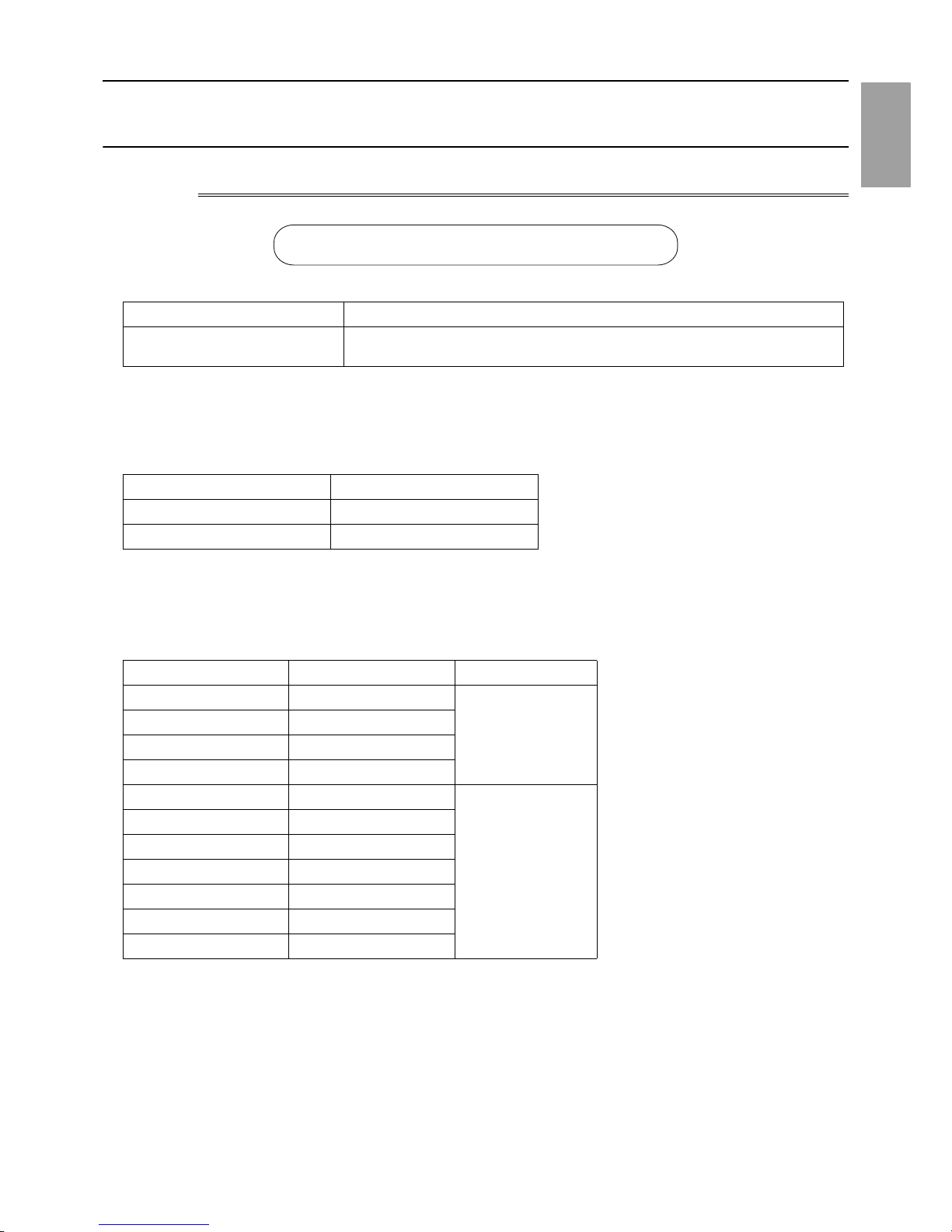
1-1-2 Tool Preparation
Prepare the following tools and materials necessary for installing and servicing the un it.
Tools for use with R410A (Adaptability of tools that are for use with R22 or R40 7C)
1. To be used exclusively with R410A (not to be used if used with R22 or R407C)
2. Tools and materials that may be used with R410A with some restrictions
3. Tools and materials that are used with R22 or R407C that may also be used with R410A
4. Tools and materials that must not be used with R410A
Tools for R410A must be handled with special care to keep moisture and dust from infiltrating the cycle.
Tools/Materials Use Notes
Gauge Manifold Evacuation and refrigerant charging Higher than 5.09MPa[738psi] on the
high-pressure side
Charging Hose Evacuation and refrigerant charging The hose diameter is larger than the
conventional model.
Refrigerant Recovery Cylinder Refrigerant recovery
Refrigerant Cylinder Refrigerant charging The refrigerant type is indicated. The
cylinder is pink.
Charging Port on the Refrigerant Cylinder Refrigerant charging The charge port diameter is larger
than that of the current port.
Flare Nut Connection of the unit with the pipes Use Type-2 Flare nuts.
Tools/Materials Use Notes
Gas Leak Detector Gas leak detection The ones for use with HFC refrigerant
may be used.
Vacuum Pump Vacuum drying May be used if a check valve adapter
is attached.
Flare Tool Flare processing Flare processing dimensions for the
piping in the system using the new re-
frigerant differ from those of R22. Re-
fer to the following page(s). [1-2-1
Piping Materials](page 5)
Refrigerant Recovery Equipment Refrigerant recovery May be used if compatible with
R410A.
Tools/Materials Use Notes
Vacuum Pump with a Check Valve Vacuum drying
Bender Bending pipes
Torque Wrench Tightening flare nuts Only the flare processing dimensions
for pipes that have a diameter of
ø12.7 (1/2") and ø15.88 (5/8") have
been changed.
Pipe Cutter Cutting pipes
Welder and Nitrogen Cylinder Welding pipes
Refrigerant Charging Meter Refrigerant charging
Vacuum Gauge Vacuum level check
Tools/Materials Use Notes
Charging Cylinder Refrigerant charging Prohibited to use
[1-2 Handling and Characteristics of Piping Materials, Refrigerant, and Refrigerant Oil ]
- 5 -
HWE14040 GB
1 Check Before Servicing
1-2 Handling and Characteristics of Piping Materials,
Refrigerant, and Refrigerant Oil
1-2-1 Piping Materials
1. Copper pipe materials
The distinction between O-materials (Annealed) and 1/2H-materials (Drawn) is made based on the strength of the pipes them-
selves.
O-materials (Annealed) can easily be bent with hands.
1/2H-materials (Drawn) are considerably stronger than O-material (Annealed) at the same thickness.
2. Types of copper pipes
3. Piping materials/Radial thickness
Use refrigerant pipes made of phosphorus deoxidized copper.
The operation pressure of the units that use R410A is higher than that of the units that use R22.
Use pipes that have at least the radial thickness specified in the chart below.
(Pipes with a radial thickness of 0.7 mm or less may not be used.)
Annealed pipes have been used for older model units when a diameter of the pipe is up to 19.05 (3/4"). For a system that
uses R410A, use pipes that are made with 1/2H-material (Drawn). (Annealed pipes may be used for pipes with a diameter of
19.05 (3/4") and a radial thickness of 1.2 t).
The figures in the radial thickness column are based on the Japanese standards and provided only as a reference. Use pipes
that meet the local standards.
O-material (Annealed) Soft copper pipes (annealed copper pipes). They can easily be bent with hands.
1/2H-material (Drawn) Hard copper pipes (straight pipes). They are stronger than the O-material (Annealed)
at the same radial thickness.
Maximum working pressure R efrigerant type
3.45 MPa [500psi] R22, R407C etc.
4.30 MPa [624psi] R410A etc.
Pipe size (mm[in]) Radial thickness (mm) Type
ø6.35 [1/4"] 0.8t
O-material (Annealed)
ø9.52 [3/8"] 0.8t
ø12.7 [1/2"] 0.8t
ø15.88 [5/8"] 1.0t
ø19.05 [3/4"] 1.0t
1/2H-material,
H-material (Drawn)
ø22.2 [7/8"] 1.0t
ø25.4 [1"] 1.0t
ø28.58 [1-1/8"] 1.0t
ø31.75 [1-1/4"] 1.1t
ø34.93 [1-3/8"] 1.2t
ø41.28 [1-5/8"] 1.4t
Do not use the existing piping!
[1-2 Handling and Characteristics of Piping Materials, Refrigerant, and Refrigerant Oil ]
- 6 -
HWE14040 GB
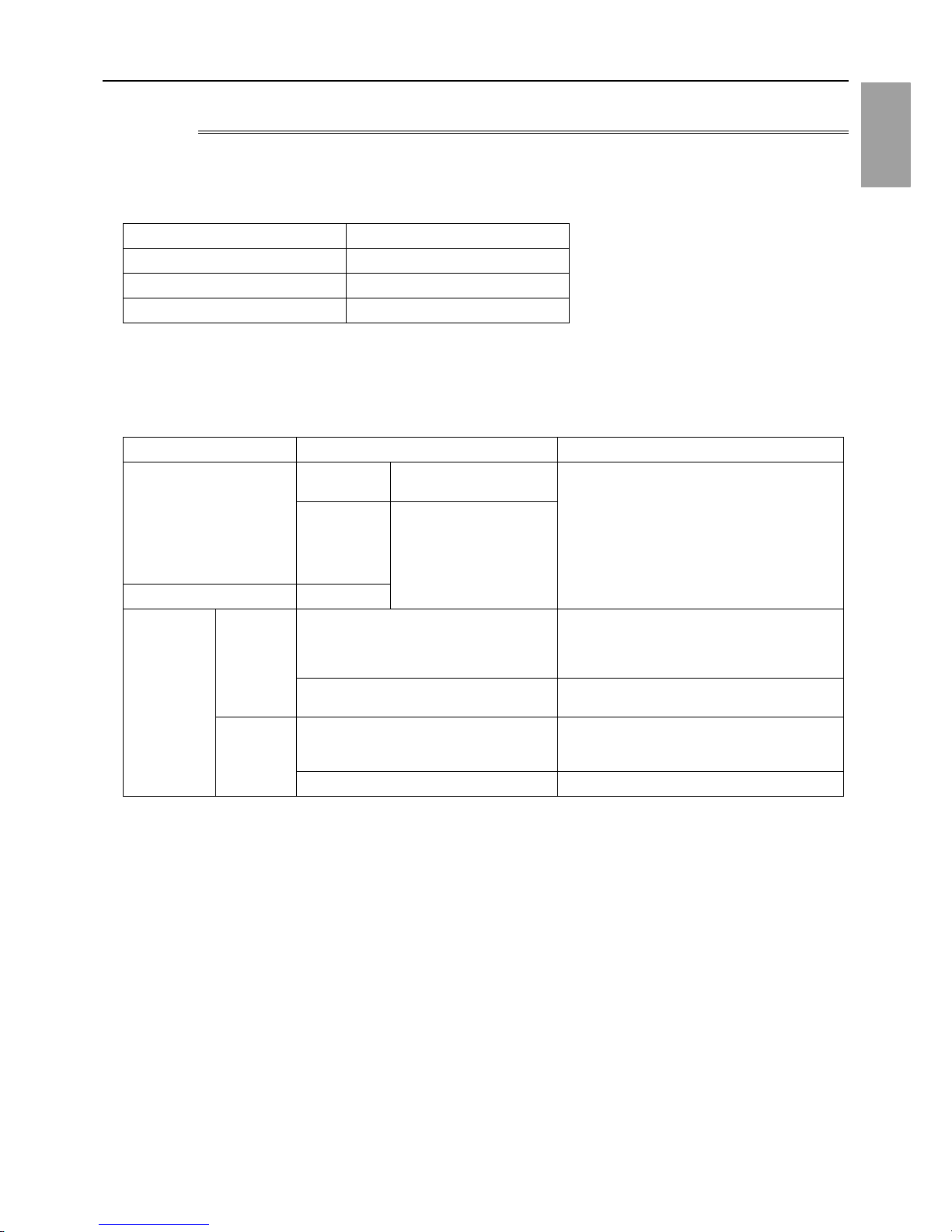
4. Thickness and refrigerant type indicated on the piping materials
Ask the pipe manufacturer for the symbols indicated on the piping material for new refrigerant.
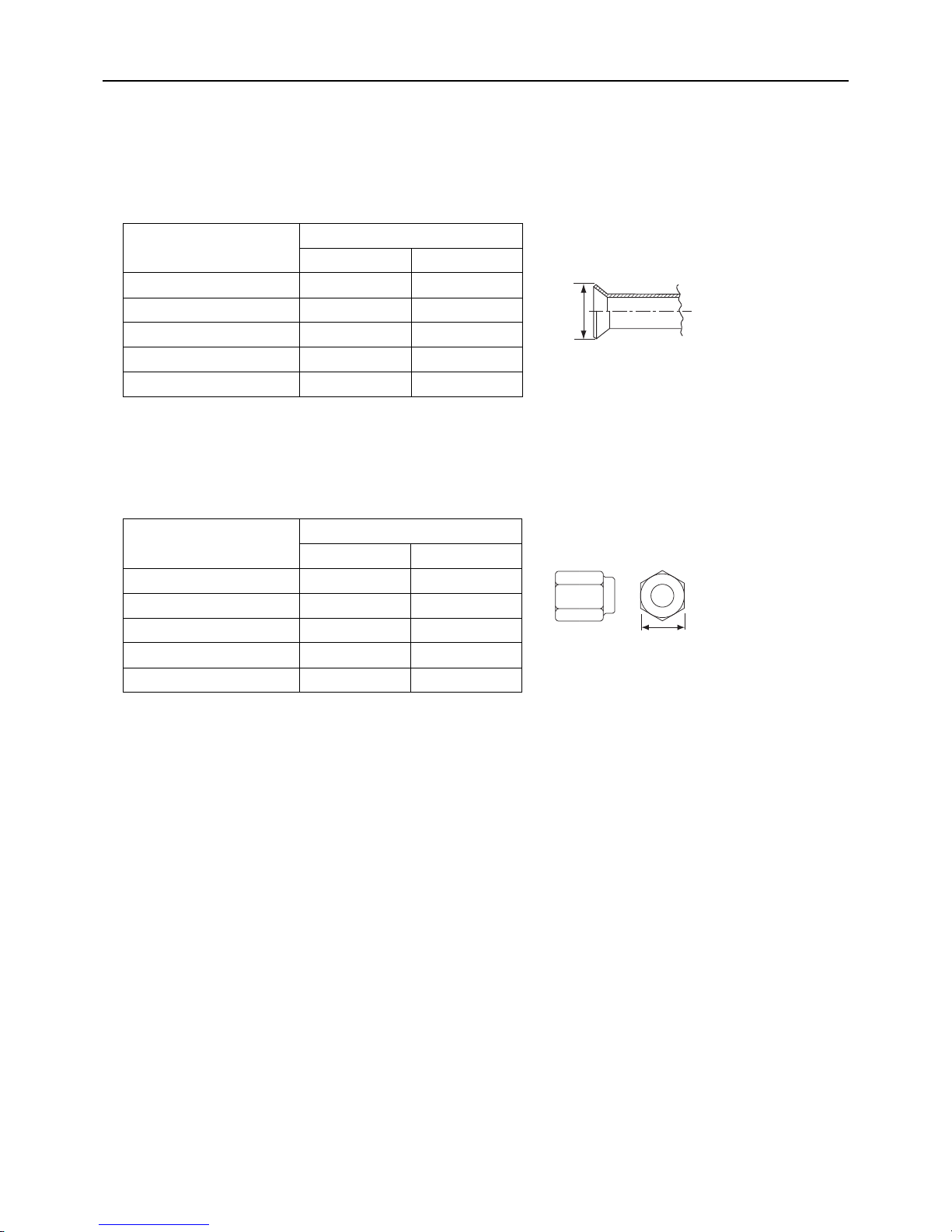
5. Flare processing (O-material (Annealed) and OL-material only)
The flare processing dimensions for the pipes that are used in the R410A system are larger than those in the R22 system.
If a clutch-type flare tool is used to flare the pipes in the system using R410A, the length of the pipes must be between 1.0
and 1.5 mm. For margin adjustment, a copper pipe gauge is necessary.
6. Flare nut
The flare nut type has been changed to increase the strength. The size of some of the flare nuts have also been changed.
The figures in the radial thickness column are based on the Japanese standards and provided only as a reference. Use pipes
that meet the local standards.
Flare processing dimensions (mm[in])
Pipe size (mm[in])
A dimension (mm)
R410A R22, R407C
ø6.35 [1/4"] 9.1 9.0
ø9.52 [3/8"] 13.2 13.0
ø12.7 [1/2"] 16.6 16.2
ø15.88 [5/8"] 19.7 19.4
ø19.05 [3/4"] 24.0 23.3
Flare nut dimensions (mm[in])
Pipe size (mm[in])
B dimension (mm)
R410A R22, R407C
ø6.35 [1/4"] 17.0 17.0
ø9.52 [3/8"] 22.0 22.0
ø12.7 [1/2"] 26.0 24.0
ø15.88 [5/8"] 29.0 27.0
ø19.05 [3/4"] 36.0 36.0
Dimension A
Dimension B
[1-2 Handling and Characteristics of Piping Materials, Refrigerant, and Refrigerant Oil ]
- 7 -
HWE14040 GB
1 Check Before Servicing
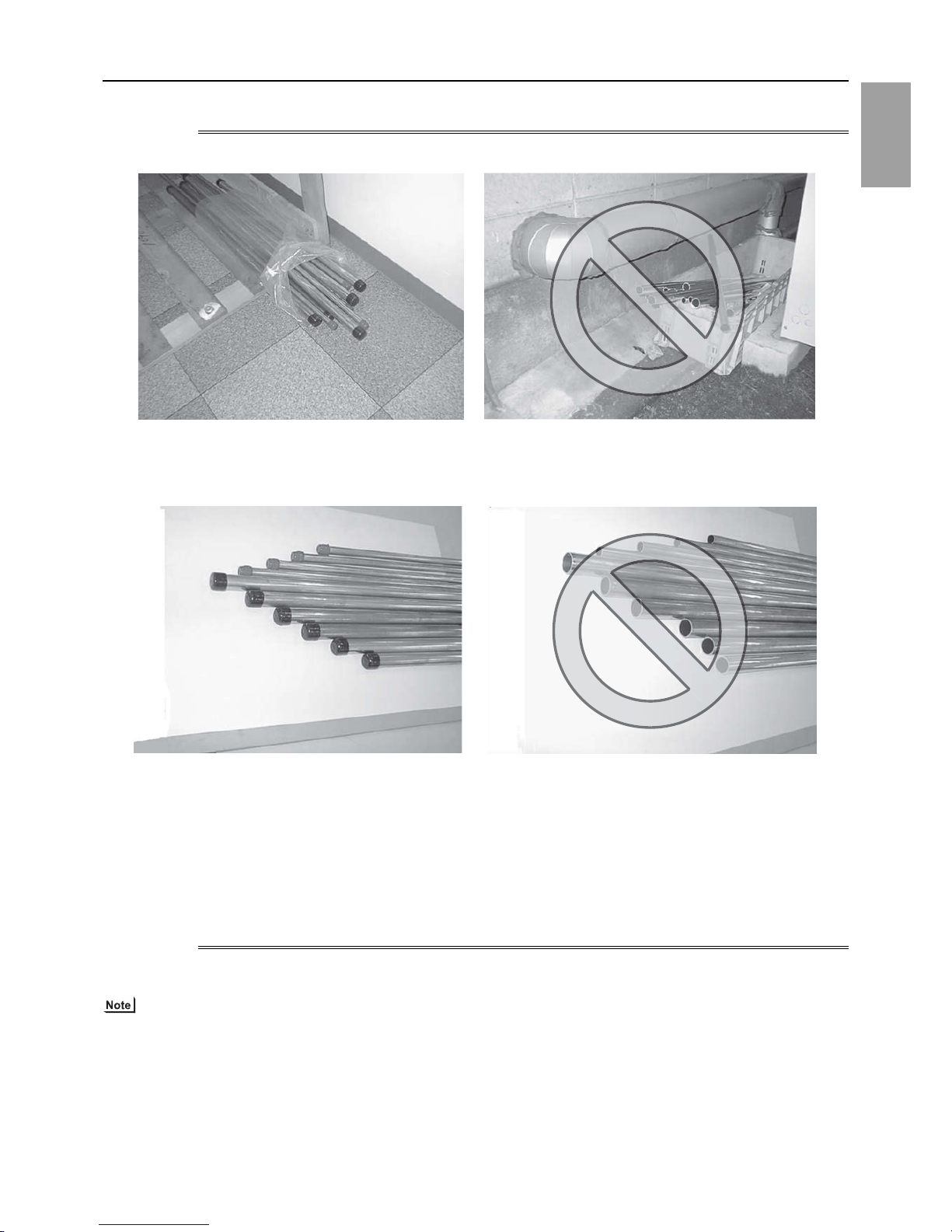
1-2-2 Storage of Piping Materials
1. Storage location
Store the pipes to be used indoors. (Warehouse at site or owner's warehouse)
If they are left outdoors, dust, dirt, or moisture may infiltrate and contaminate the pipe.
2. Sealing the pipe ends
Both ends of the pipes should be sealed until just before brazing.
Keep elbow pipes and T-joints in plastic bags.
The new refrigerator oil is 10 times as hygroscopic as the conventional refrigerating machine oil (such as Suniso) and, if not
handled with care, could easily introduce moisture into the system. Keep moisture out of the pipes, for it will cause the oil to
deteriorate and cause a compressor failure.
1-2-3 Pipe Processing
Use a small amount of ester oil, ether oil, or alkylbenzene to coat flares and flanges.
Use a minimum amount of oil.
Use only ester oil, ether oil, and alkylbenzene.
[1-2 Handling and Characteristics of Piping Materials, Refrigerant, and Refrigerant Oil ]
- 8 -
HWE14040 GB
1-2-4 Characteristics of the New and Conventional Refrigerants
1. Chemical property
As with R22, the new refrigerant (R410A) is low in toxicity and chemically stable nonflammable refrigerant.
However, because the specific gravity of vapor refrigerant is greater than that of air, leaked refrigerant in a closed room will
accumulate at the bottom of the room and may cause hypoxia.
If exposed to an open flame, refrigerant will generate poisonous gases. Do not perform installation or service work in a confined area.
*1 When CFC11 is used as a reference
*2 When CO2 is used as a reference
2. Refrigerant composition
R410A is a pseudo-azeotropic HFC blend and can almost be handled the same way as a single refrigerant, such as R22. To
be safe, however, draw out the refrigerant from the cylinder in the liquid phase. If the refrigerant in the gaseous phase is drawn
out, the composition of the remaining refrigerant will change and become unsuitable for use.
If the refrigerant leaks out, it may be replenished. The entire refrigerant does not need to be replaced.
3. Pressure characteristics
The pressure in the system using R410A is 1.6 times as great as that in the system using R22.
New Refrigerant (HFC type) Conventional Refriger-
ant (HCFC type)
R410A R407C R22
R32/R125 R32/R125/R134a R22
Composition (wt%) (50/50) (23/25/52) (100)
Type of Refrigerant Pseudo-azeotropic
Refrigerant
Non-azeotropic
Refrigerant
Single Refrigerant
Chloride Not included Not included Included
Safety Class A1/A1 A1/A1 A1
Molecular Weight 72.6 86.2 86.5
Boiling Point (°C/°F) -51.4/-60.5 -43.6/-46.4 -40.8/-41.4
Steam Pressure
(25°C,MPa/77°F,psi) (gauge)
1.557/226 0.9177/133 0.94/136
Saturated Steam Density
(25°C,kg/m3/77°F,psi)
64.0 42.5 44.4
Flammability Nonflammable Nonflammable Nonflammable
Ozone Depletion Coefficient (ODP)
*1
0 0 0.055
Global Warming Coefficient (GWP)
*2
2090 1774 1700
Refrigerant Charging Method Refrigerant charging in
the liquid state
Refrigerant charging in
the liquid state
Refrigerant charging in
the gaseous state
Replenishment of Refrigerant after a Refrigerant
Leak
Available Available Available
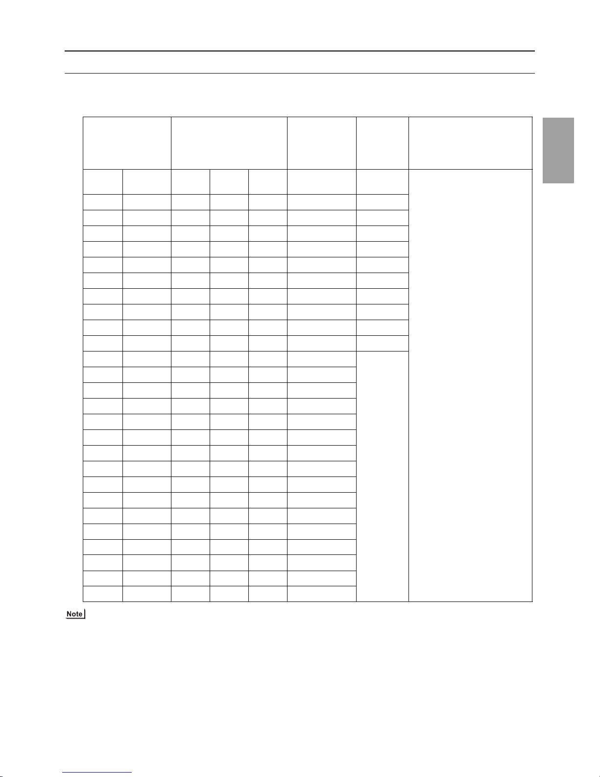
Temperature (°C/°F)
Pressure (gauge)
R410A R407C R22
MPa/psi MPa/psi MPa/psi
-20/-4 0.30/44 0.18/26 0.14/20
0/32 0.70/102 0.47/68 0.40/58
20/68 1.34/194 0.94/136 0.81/117
40/104 2.31/335 1.44/209 1.44/209
60/140 3.73/541 2.44/354 2.33/338
65/149 4.17/605 2.75/399 2.60/377
[1-2 Handling and Characteristics of Piping Materials, Refrigerant, and Refrigerant Oil ]
- 9 -
HWE14040 GB
1 Check Before Servicing
1-2-5 Refrigerant Oil
1. Refrigerating machine oil in the HFC refrigerant system
HFC type refrigerants use a refrigerating machine oil different from that used in the R22 system.
Note that the ester oil used in the system has properties that are different from commercially available ester oil.
2. Effects of contaminants
*1
Refrigerating machine oil used in the HFC system must be handled with special care to keep contaminants out.
The table below shows the effect of contaminants in the refrigerating machine oil on the refrigeration cycle.
3. The effects of contaminants in the refrigerating machine oil on the refrigeration cycle.
Refrigerant Refrigerating machine oil
R22 Mineral oil
R407C Ester oil
R410A Ester oil
*1. Contaminants is defined as moisture, air, processing oil, dust/dirt, wrong types of refrigerant, and refrigerating machine oil.
Cause Symptoms Effects on the refrigerant cycle
Water infiltration Frozen expansion valve
and capillary tubes
Clogged expansion valve and capillary tubes
Poor cooling performance
Compressor overheat
Motor insulation failure
Burnt motor
Coppering of the orbiting scroll
Lock
Burn-in on the orbiting scroll
Hydrolysis
Sludge formation and adhesion
Acid generation
Oxidization
Oil degradation
Air infiltration Oxidization
Infiltration of
contaminants
Dust, dirt
Adhesion to expansion valve and capillary
tubes
Clogged expansion valve, capillary tubes, and
drier
Poor cooling performance
Compressor overheat
Infiltration of contaminants into the compressor
Burn-in on the orbiting scroll
Mineral oil
etc.
Sludge formation and adhesion Clogged expansion valve and capillary tubes
Poor cooling performance
Compressor overheat
Oil degradation Burn-in on the orbiting scroll
[1-3 Working with Refrigerant Piping ]
- 10 -
HWE14040 GB
1-3 Working with Refrigerant Piping
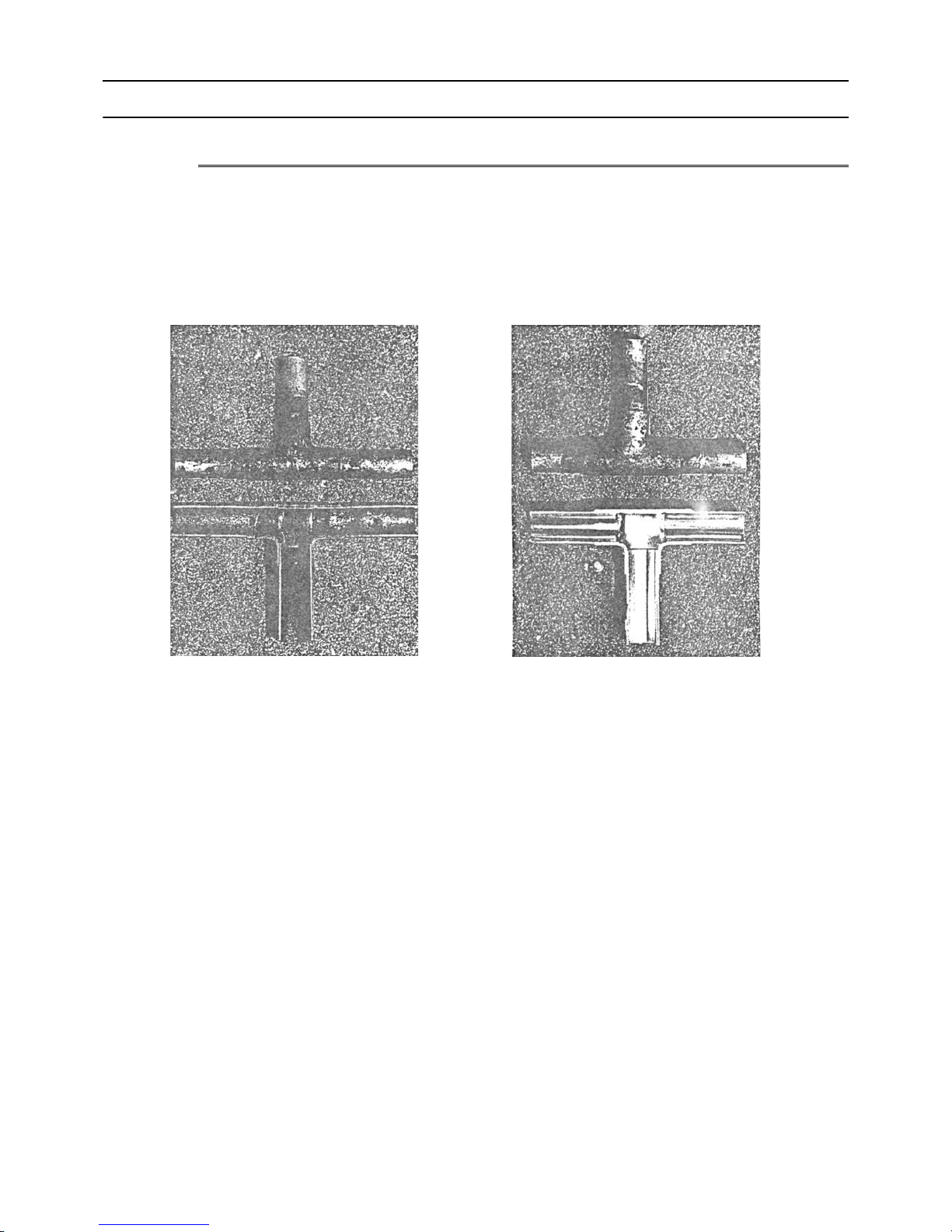
1-3-1 Pipe Brazing
No changes have been made in the brazing procedures. Perform brazing with special care to keep foreign objects (such as oxide
scale, water, and dust) out of the refrigerant system.
Example: Inside the brazed connection
1. Items to be strictly observed
Do not conduct refrigerant piping work outdoors if raining.
Use inert gas during brazing.
Use a brazing material (BCuP-3) that requires no flux when brazing between copper pipes or between a copper pipe and
copper coupling.
If installed refrigerant pipes are not immediately connected to the equipment, then braze and seal both ends.
2. Reasons
The new refrigerating machine oil is 10 times as hygroscopic as the conventional oil and is more likely to cause unit failure if
water infiltrates into the system.
Flux generally contains chloride. Residual flux in the refrigerant circuit will cause sludge to form.
3. Notes
Do not use commercially available antioxidants because they may cause the pipes to corrode or refrigerating machine oil to
deteriorate.
Use of no inert gas during brazing Use of inert gas during brazing
[1-3 Working with Refrigerant Piping ]
- 11 -
HWE14040 GB
1 Check Before Servicing
1-3-2 Air Tightness Test
No changes have been made in the detection method. Note that a refrigerant leak detector for R22 will not detect an R410A leak.
1. Items to be strictly observed
Pressurize the equipment with nitrogen up to the design pressure (4.15MPa[601psi]), and then judge the equipment's air tight-
ness, taking temperature variations into account.
Refrigerant R410A must be charged in its liquid state (vs. gaseous state).
2. Reasons
Oxygen, if used for an air tightness test, poses a risk of explosion. (Only use nitrogen to check air tightness.)
Refrigerant R410A must be charged in its liquid state. If gaseous refrigerant in the cylinder is drawn out first, the composition
of the remaining refrigerant in the cylinder will change and become unsuitable for use.
3. Notes
Procure a leak detector that is specifically designed to detect an HFC leak. A leak detector for R22 will not detect an
HFC(R410A) leak.
Halide torch R22 leakage detector
[1-3 Working with Refrigerant Piping ]
- 12 -
HWE14040 GB
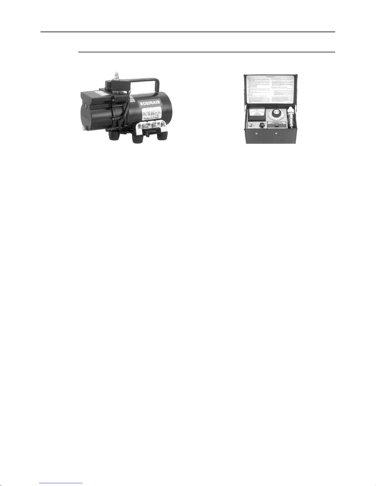
1-3-3 Vacuum Drying
1. Vacuum pump with a reverse-flow check valve (Photo1)
To prevent the vacuum pump oil from flowing into the refrigerant circuit during power OFF or power failure, use a vacuum
pump with a reverse-flow check valve.
A reverse-flow check valve may also be added to the vacuum pump currently in use.
2. Standard of vacuum degree (Photo 2)
Use a vacuum pump that attains 0.5Torr(65Pa) or lower degree of vacuum after 5 minutes of operation, and connect it directly
to the vacuum gauge. Use a pump well-maintained with an appropriate lubricant. A poorly maintained vacuum pump may not
be able to attain the desired degree of vacuum.
3. Required precision of vacuum gauge
Use a vacuum gauge that registers a vacuum degree of 5Torr(650Pa) and measures at intervals of 1Torr(130Pa). (A recommended vacuum gauge is shown in Photo2.)
Do not use a commonly used gauge manifold because it cannot register a vacuum degree of 5Torr(650Pa).
4. Evacuation time
After the degree of vacuum has reached 5Torr(650Pa), evacuate for an additional 1 hour. (A thorough vacuum drying re-
moves moisture in the pipes.)
Verify that the vacuum degree has not risen by more than 1Torr(130Pa) 1hour after evacuation. A rise by less than
1Torr(130Pa) is acceptable.
If the vacuum is lost by more than 1Torr(130Pa), conduct evacuation, following the instructions in section 6. Special vacuum
drying.
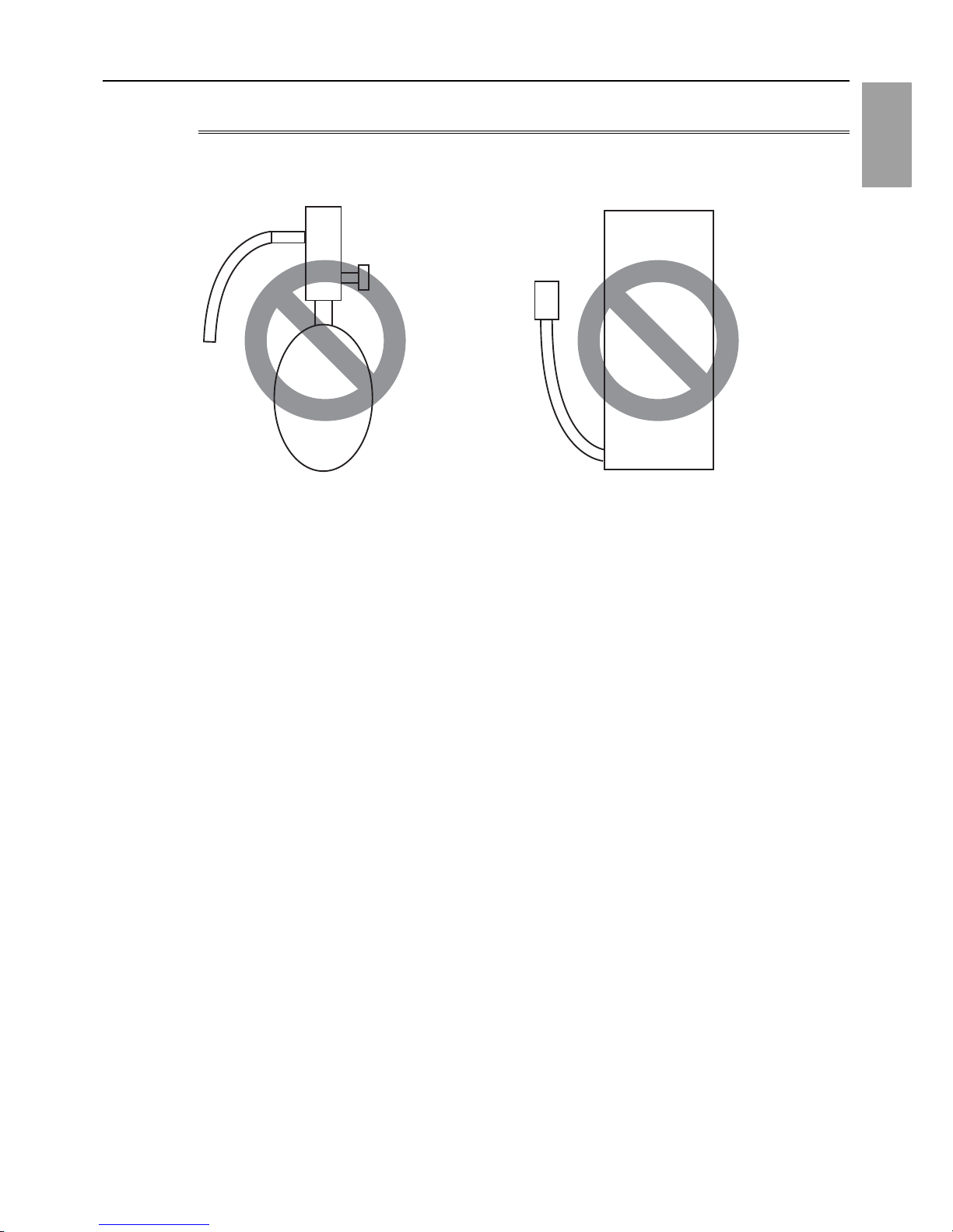
5. Procedures for stopping vacuum pump
To prevent the reverse flow of vacuum pump oil, open the relief valve on the vacuum pump side, or draw in air by loosening
the charge hose, and then stop the operation.
The same procedures should be followed when stopping a vacuum pump with a reverse-flow check valve.
6. Special vacuum drying
When 5Torr(650Pa) or lower degree of vacuum cannot be attained after 3 hours of evacuation, it is likely that water has pen-
etrated the system or that there is a leak.
If water infiltrates the system, break the vacuum with nitrogen. Pressurize the system with nitrogen gas to
0.5kgf/cm
2
G(0.05MPa) and evacuate again. Repeat this cycle of pressurizing and evacuation either until the degree of vac-
uum below 5Torr(650Pa) is attained or until the pressure stops rising.
Only use nitrogen gas for vacuum breaking. (The use of oxygen may result in an explosion.)
(Photo1) 15010H (Photo2) 14010
Recommended vacuum gauge:
ROBINAIR 14010 Thermistor Vacuum Gauge
[1-3 Working with Refrigerant Piping ]
- 13 -
HWE14040 GB
1 Check Before Servicing
1-3-4 Refrigerant Charging
1. Reasons
R410A is a pseudo-azeotropic HFC blend (boiling point R32=-52°C[-62°F], R125=-49°C[-52°F]) and can almost be han dled
the same way as a single refrigerant, such as R22. To be safe, however, draw out the refrigerant from the cylinder in the liquid
phase. If the refrigerant in the gaseous phase is drawn out, the composition of the remaining refrigeran t will change and become unsuitable for use.
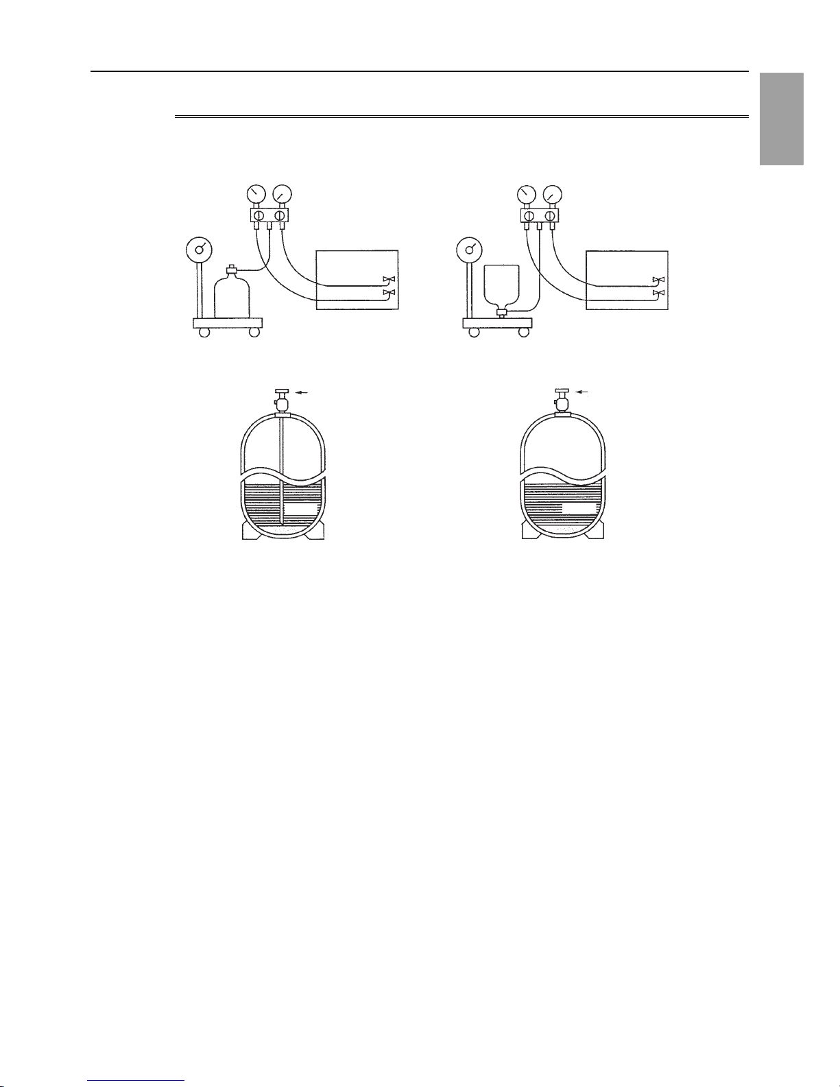
2. Notes
When using a cylinder with a siphon, refrigerant is charged in the liquid state without the need for turning it upside down. Check
the type of the cylinder on the label before use.
If the refrigerant leaks out, it may be replenished. The entire refrigerant does not need to be replaced. (Charge refrigerant in
the liquid state.)
Refer to the following page(s).[8-11 Measures for Refrigerant Leakage](page 281)
Cylinder with a siphon
Cylinder color R410A is pink. Refrigerant charging in the liquid state
Cylinder
liquid
Valve Valve
liquid
Cylinder
Cylinder without a siphon
[1-4 Precautions for Wiring ]
- 14 -
HWE14040 GB
1-4 Precautions for Wiring
Control boxes house high-voltage and high-temperature electrical parts.
They may still remain energized or hot after the power is turned off.
When opening or closing the front cover of the control box, keep out of contact with the internal parts.
Before inspecting the inside of the control box, turn off the power, leave the unit turned off for at leas t 10 minu tes, and ch eck
that the voltage of the electrolytic capacitor (inverter main circuit) has dropped to 20 VDC or less.
It will take approximately 10 minutes until the voltage is discharged after power off.
Disconnect the outdoor unit fan board connector (CNINV) before performing maintenance work.
Before connecting or disconnecting the connector, check that the outdoor unit fan is stopped and that the voltage of the main
circuit capacitor has dropped to 20 VDC or below.
If the outdoor unit fan is rotated by external forces such as strong winds, the main circuit capacitor can be charged and cause
an electric shock.
Refer to the wiring nameplate for details.
Reconnect the connector (CNINV) to the fan board after completion of maintenance work.
When the power is on, the compressor or heater is energized even while the compressor is stopped.
It is energized to evaporate the liquid refrigerant that has accumulated in the compressor.
Before connecting wiring to TB7, check that the voltage has dropped below 20 VDC.
When a system controller is connected to the centralized control transmission cable to which power is supplied from the out-
door unit (power jumper on the outdoor unit is connected to CN40), be aware that power can be supplied to the centralized
control transmission and the system controller may detect an error and send an error notice if the outdoor unit fan is rotated
by external forces, such as strong winds, even when power to the outdoor unit is turned off.
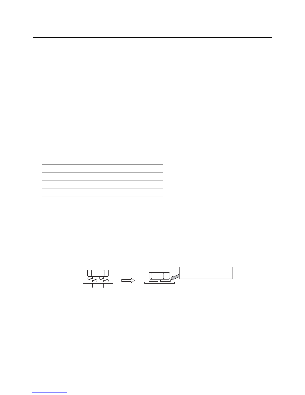
When replacing the internal electrical components of the control box, tighten the screws to the recommended tightening
torque as specified below.
Recommended tightening torque for the internal electrical components of the control box
1 When replacing semiconductor modules (e.g., diode stack, IPM, INV board (with IPM), fan board (with IPM)), apply heat-
sink silicone evenly to the mounting surface of the semiconductor module (or the semiconductor module on the back of
the circuit board). Next, tighten the screws holding the semiconductor module to one-third of the specified torque, and then
tighten the screws to the specified torque.
2 Deviating from the recommended tightening torque may cause damage to the unit or its parts.
Take the following steps to ensure that the screws are properly tightened.
1) Ensure that the spring washers are parallel to the terminal block.
Even if the tightening torque is observed, if the washers are not parallel to the terminal block, then the semiconductor module
is not installed properly.
Screw Recommended tightening torque (N·m)
M3 0.69
M4 1.47
M5 2.55
M6 2.75
M8 6.20
Proper installation
Loose screws
Spring washers are parallel to
the terminal block
[1-4 Precautions for Wiring ]
- 15 -
HWE14040 GB
1 Check Before Servicing
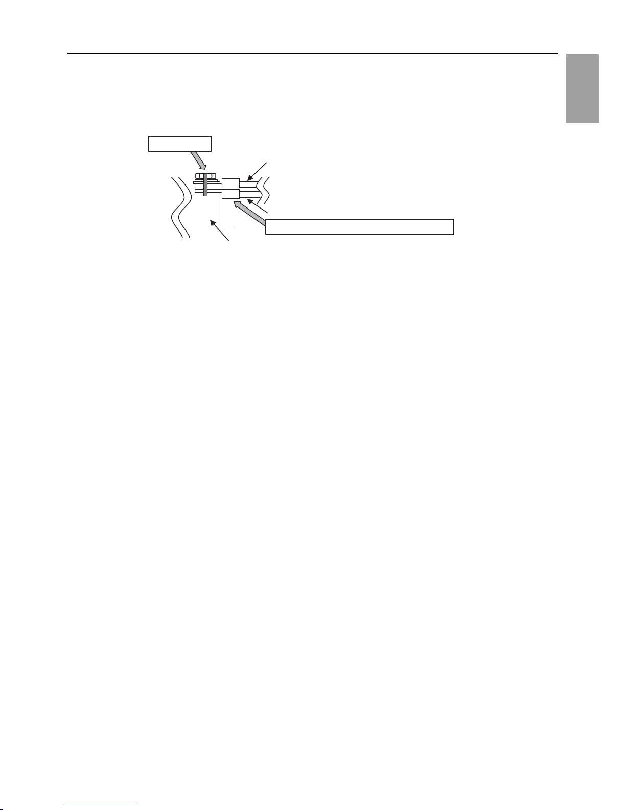
2) Check the wires are securely fastened to the screw terminals.
Screw the screws straight down so as not to damage the screw threads.
Hold the two round terminals back to back to ensure that the screw will screw down straight.
After tightening the screw, mark a line through the screw head, washer, and terminals with a permanent marker.
Example
Poor contact caused by loose screws may result in overheating and fire.
Continued use of the damaged circuit board may cause overheating and fire.
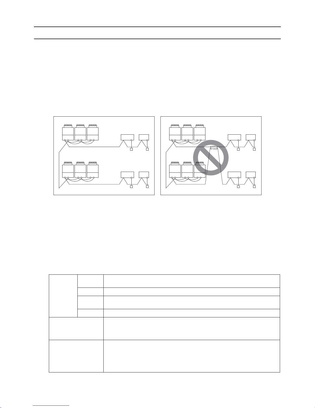
Daisy-chain
Power supply terminal block, indoor-outdoor transmission line terminal block,
and centralized controller transmission line
Mark a line.
Place the round terminals back to back.
Power wires, transmission lines, centralized transmission lines

[1-5 Cautionary notes on installation environment and maintenance ]
- 16 -
HWE14040 GB
1-5 Cautionary notes on installation environment and
maintenance
Salt-resistant unit is resistant to salt corrosion, but not salt-proof. Please note the following when installing and maintaining outdoor units in marine atmosphere.
1) Install the salt-resistant unit out of direct exposure to sea breeze, and minimize the exposure to salt water mist.
2) Avoid installing a sun shade over the outdoor unit, so that rain will wash away salt deposits off the unit.
3) Install the unit horizontally to ensure proper water drainage from the base of the unit. Accumulation of water in the base of the
outdoor unit will significantly accelerate corrosion.
4) Periodically wash salt deposits off the unit, especially when the unit is installed in a coastal area.
5) Repair all noticeable scratches after installation and during maintenance.
6) Periodically check the unit, and apply anti-rust agent and replace corroded parts as necessary.

- 17 -
HWE14040 GB
Chapter 2 Restrictions
2-1 System Configurations............................................................. ..........................................................19
2-2 Types and Maximum Allowable Length of Cables...........................................................................20
2-3 Switch Settings ................................................... .. ... ..................................... .. .................................... 21
2-4 M-NET Address Settings....................................................................................................................22
2-4-1 Address Settings List ............................................................................................................................22
2-4-2 Outdoor Unit Power Jumper Connector Connection.............................................................................23
2-4-3 Outdoor Unit Centralized Controller Switch Setting.............................................................................. 23
2-4-4 Room Temperature Detection Position Selection.................................................................................23
2-4-5 Start/Stop Control of Indoor Units.........................................................................................................24
2-4-6 Miscellaneous Settings ....................................................... ....................................... ... ........................24
2-4-7 Various Control Methods Using the Signal Input/Output Connector on Outdoor Unit .......................... 25
2-5 Demand Control Overview..................... ... .........................................................................................28
2-6 System Connection Example............................................................................................................. 30
2-7 Example System with an MA Remote Controller............................................................................. 32
2-7-1 Single Refrigerant System (Automatic Indoor/Outdoor Address Startup)............................................. 32
2-7-2 Single Refrigerant System with Two or More LOSSNAY Units ............................................................ 34
2-7-3 Grouped Operation of Units in Separate Refrigerant Circuits............................................................... 36
2-7-4 System with a Connection of System Controller to Centralized Control Transmission Line................. 38
2-7-5 System with a Connection of System Controller to Indoor-Outdoor Transmission Line ....................... 40
2-8 Example System with an ME Remote Controller .............................................................................42
2-8-1 System with a Connection of System Controller to Centralized Control Transmission Line................. 42
2-9 Example System with an MA and an ME Remote Controller..........................................................44
2-9-1 System with a Connection of System Controller to Centralized Control Transmission Line................. 44
2-10 Restrictions on Refrigerant Pipes..................................................................................................... 46
2-10-1 Restrictions on Refrigerant Pipe Length ............................................................................................... 46
2-10-2 Restrictions on Refrigerant Pipe Size ...................................................................................................49

- 18 -
HWE14040 GB
[2-1 System Configurations ]
- 19 -
HWE14040 GB
2 Restrictions
2 Restrictions
2-1 System Configurations
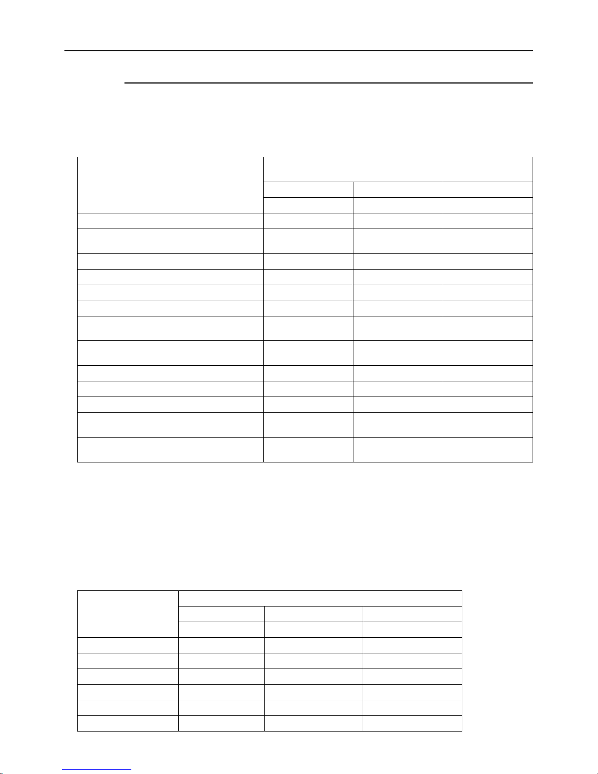
1. Table of compatible indoor units
(1) High COP combinations
The table below summarizes the types of indoor units that are compatible with different types of outdoor units.
1) "Maximum total capacity of connectable indoor units" refers to the sum of the numeric values in the indoor unit model names.
2) If the total capacity of the indoor units that are connected to a given outdoor unit exceeds the capacity of the outdoor unit, the
indoor units will not be able to perform at the rated capacity when they are operated simultaneously. Select a combination of
units so that the total capacity of the connected indoor units is at or below the capacity of the outdoor unit whenever possible.
Outdoor units Composing units Maximum total
capacity of con-
nectable indoor
units
Maximum
number of
connect-
able indoor
units
Types of connectable
indoor units
P200 YKB-A1 - - - 100 - 260 17
P15 - P250 models
R410A series indoor units
P250 YKB-A1 - - - 125 - 325 21
P300 YKB-A1 - - - 150 - 390 26
P350 YKB-A1 - - - 175 - 455 30
P400 YKB-A1 - - - 200 - 520 34
P450 YKB-A1 - - - 225 - 585 39
P500 YKB-A1 - - - 250 - 650 43
P400 YSKB-A1 P200 P200 - 200 - 520 34
P450 YSKB-A1 P250 P200 - 225 - 585 39
P500 YSKB-A1 P250 P250 - 250 - 650 43
P550 YSKB-A1 P300 P250 - 275 - 715 47
P600 YSKB-A1 P350 P250 - 300 - 780 50
P650 YSKB-A1 P350 P300 - 325 - 845
P700 YSKB-A1 P350 P350 - 350 - 910
P750 YSKB-A1 P400 P350 - 375 - 975
P800 YSKB-A1 P450 P350 - 400 - 1040
P850 YSKB-A1 P450 P400 - 425 - 1105
P900 YSKB-A1 P450 P450 - 450 - 1170
P950 YSKB-A1 P400 P300 P250 475 - 1235
P1000 YSKB-A1 P400 P300 P300 500 - 1300
P1050 YSKB-A1 P400 P350 P300 525 - 1365
P1100 YSKB-A1 P400 P350 P350 550 - 1430
P1150 YSKB-A1 P450 P350 P350 575 - 1495
P1200 YSKB-A1 P450 P400 P350 600 - 1560
P1250 YSKB-A1 P450 P450 P350 625 - 1625
P1300 YSKB-A1 P450 P450 P400 650 - 1690
P1350 YSKB-A1 P450 P450 P450 675 - 1755
[2-2 Types and Maximum Allowable Length of Cables ]
- 20 -
HWE14040 GB
2-2 Types and Maximum Allowable Length of Cables
1. Wiring work
(1) Notes
1) Have all electrical work performed by an authorized electrician according to the local regulations and instructions in this manual.
2) Install external transmission cables at least 5cm [1-31/32"] away from the power supply cable to avoid noise interference.
(Do not put the control cable and power supply cable in the same conduit tube.)
3) Provide grounding for the outdoor unit as required.
4) Run the cable from the electric box of the indoor or outdoor unit in such way that the box is accessible for servicing.
5) Do not connect power supply wiring to the terminal block for transmission cable. Doing so will damage the electronic components on the terminal block.
6) Use 2-core shielded cables as transmission cables.
Do not use a single multiple-core cable to connect indoor units that belong to different refrigerant systems. Doing so may result
in signal transmission errors and malfunctions..
7) When extending the transmission cable, be sure to extend the shield wire.
(2) Control wiring
Different types of control wiring are used for different systems. Before performing wiring work, refer to the following page(s).
[2-7 Example System with an MA Remote Controller](page 32)
[2-8 Example System with an ME Remote Controller](page 42)
[2-9 Example System with an MA and an ME Remote Controller](page 44)
Types and maximum allowable length of cables
Control lines are categorized into 2 types: transmission line and remote controller line.
Use the appropriate type of cables and observe the maximum allowable length specified for a given system. If a given system
has a long transmission line or if a noise source is located near the unit, place the unit away from the noise source to reduce
noise interference.
1) M-NET transmission line
Cable type
Facility
type
All facility types
Type Shielded cable CVVS, CPEVS, MVVS
Number of
cores
2-core cable
Cable size Larger than 1.25mm
2
[AWG16]
Maximum transmission
line distance between the
outdoor unit and the farthest indoor unit
200 m [656ft] max.
Maximum transmission
line distance for centralized control and Indoor/
outdoor transmission line
(Maximum line distance
via outdoor unit)
500 m [1640ft] max.
*The maximum overall line length from the power supply unit on the transmission lines for
centralized control to each outdoor unit or to the system controller is 200m [656ft] max.
TB 3 TB 7 TB 3 TB
7
TB
3
TB 3 TB
7
TB
7
TB 3 TB
7
TB
3
TB
7
TB 3 TB 7 TB 3 TB
7
TB
3
TB 3 TB
7
TB
7
TB 3 TB
7
TB
3
TB
7
2-core shielded cable
2-core shielded cable
Indoor unit
Outdoor unit
TB3: Terminal block for indoor-outdoor transmission line TB7: Terminal block for centralized control
Remote Controller
Indoor unit
Outdoor unit
Remote Controller
multiple-core cable
[2-3 Switch Settings ]
- 21 -
HWE14040 GB
2 Restrictions
2) Remote controller wiring
*1 MA remote controller refers to MA remote controller (PAR-31MAA, PAR-21MAA), MA simple remote controller, and
wireless remote controller.
*2 ME remote controller refers to ME remote controller, Compact ME remote controller, and LOSSNAY remote control-
ler.
*3 The use of cables that are smaller than 0.75mm
2
(AWG18) is recommended for easy handling.
*4 When connected to the terminal block on the Simple remote controller, use cabl es that meet the cable size specifi-
cations shown in the parenthesis.
*5 When connecting PAR-31MAA or MA Simple remote controller, use sheathed cables with a minimum thickness of
0.3 mm
2
.
2-3 Switch Settings
1. Switch setting
The necessary switch settings depend on system configuration. Before performing wiring work, refer to the following page(s).
[2-7 Example System with an MA Remote Controller](page 32)
[2-8 Example System with an ME Remote Controller](page 42)
[2-9 Example System with an MA and an ME Remote Controller](page 44)
If the switch settings are changed while the unit is being powered, those changes will not take effect, and the unit will not
function properly.
*1. Applicable when LOSSNAY units are connected to the indoor-outdoor transmission line.
*2. The outdoor units in the same refrigerant circuit are automatically designated as OC, OS1, and OS2 in the order of
capacity from large to small (if two or more units have the same capacity, in the order of address from small to large).
*3. Turn off the power to all the outdoor units in the same refrigerant circuit.
*4. When setting the switch SW4 of the control board, set it with the outdoor unit power on. Refer to the following page(s).
[5-1-1 Outdoor Unit Switch Functions and Factory Settings](page 85)
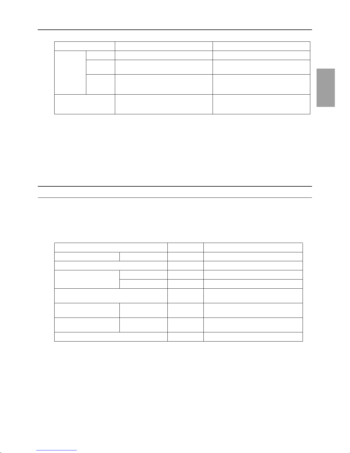
MA remote controller
*1
ME remote controller
*2
Cable type
Type VCTF, VCTFK, CVV, CVS, VVR, VVF, VCT Shielded cables CVVS, CPEVS, and MVVS
Number of
cores
2-core cable 2-core cable
Cable size
0.3 to 1.25mm
2 *3 *5
[AWG22 to 16]
0.3 to 1.25mm
2 *3
[AWG22 to 16]
(0.75 to 1.25mm2 )
*4
[AWG18 to 16]
Maximum overall line
length
200 m [656ft] max.
The section of the cable that exceeds 10m
[32ft] must be included in the maximum indoor-outdoor transmission line distance.
Units on which to set the switches Symbol Units to which the power must be shut off
CITY MULTI indoor unit Main/sub unit IC Outdoor units
*3
and Indoor units
LOSSNAY, OA processing unit
*1
LC Outdoor units
*3
and LOSSNAY
ATW Booster Unit BU Outdoor units and Booster Unit
Water Hex Unit AU Outdoor units and Water Hex Unit
Air handling kit IC Outdoor units
*3
or field supplied air handling
unit
ME remote controller Main/sub remote
controller
RC Outdoor units
*3
MA remote controller
*4
Main/sub remote
controller
MA Indoor units
CITY MULTI outdoor unit
*2
OC,OS1,OS2 Outdoor units
*3 *5
 Loading...