

Mitsubishi PUHY-P550, PUHY-P450, PUHY-P600, PUHY-P650YGM-A, PUHY-P350YGM-A Service Handbook
...
Models PUHY-P200, P250, P300, P350, P400YGM-A
PUHY-P450, P500, P550, P600, P650YGM-A
PUY-P200, P250, P300, P350YGM-A
Service Handbook
AIR CONDITIONERS CITY MULTI

Contents
1 Read Before Servicing ................................................................ 6
[1] Items to Be Checked .............................................................. 6
[2] Necessary Tools and Materials .............................................. 7
[3] Piping Materials ...................................................................... 8
[4] Storage of Piping Material ...................................................... 10
[5] Piping Machining .................................................................... 11
[6] Brazing.................................................................................... 12
[7]
Airtightness Test
...................................................................... 13
[8] Vacuuming .............................................................................. 13
[9] Vacuum Drying........................................................................ 14
[10] Changing Refrigerant.............................................................. 15
[11] Remedies to be taken in case of a refrigerant leak................ 15
[12]
Characteristics of the Conventional and the New Refrigerants
.. 16
[13] Notes on Refrigerating Machine Oil........................................ 17
2 Restrictions .................................................................................. 18
[1] Electrical Work & M-NET control............................................ 18
[2] Types of Switch Setting and Address Setting ........................ 19
[3] Examples of system connection ............................................ 21
[4] Restrictions on Refrigerant Piping Length.............................. 35
3 Components of the Outdoor Unit ................................................ 37
[1] Appearance of the Components and Refrigerant Circuit........ 37
[2] Control Box ............................................................................ 43
[3] Circuit Board .......................................................................... 45
4 Remote Controller........................................................................ 49
[1]
Functions and Specifications of MA and ME Remote Controllers
.... 49
[2] Group Setting and Interlocking Settings that are Made on
the ME Remote Controller .................................................... 50
[3]
Interlocking Setting that is Made on the MA Remote Controller
...... 53
[4] Switching to the built-in Thermo on the remote controller...... 54
5 Electrical Wiring Diagram ............................................................ 55
[1]
PUHY-P200, P250, P300, P350, P400YGM-A / PUY-P200, P250, P300, P350YGM-A
.. 55
[2]
PUHY-P450, P500, P550, P600, P650YGM-A
.............................. 56
[3]
Power Dispatching Extension Unit for the Transmission Lines
........ 57
6 Refrigerant Circuit ........................................................................ 58
[1] Refrigerant Circuit Diagram .................................................... 58
[2] Functions of Principal Parts.................................................... 62
7 Control.......................................................................................... 64
[1] Dip Switch Functions and Their Factory Settings .................. 64
[2] Controlling the Outdoor Unit .................................................. 69
[3] Operation Flow Chart ............................................................ 76
8 Test Run ...................................................................................... 81
[1] Check Items before Test Run.................................................. 81
[2] Test Run Method .................................................................... 81
[3] Operating Characteristics and Refrigerant Amount................ 82
[4] Adjustment and Judgment of Refrigerant Amount ................ 82
[5] Refrigerant Volume Adjustment Mode Operation .................. 84
[6] Symptoms that do not Signify Problems ................................ 86
[7]
Standard Operation Data (Reference Data)
.............................. 87
9 Troubleshooting ............................................................................ 95
[1] Check Code List .................................................................... 95
[2] Responding to Error Display on the Remote Controller ........ 98
[3] Investigation of Transmission Wave Shape/Noise .................. 131
[4] Troubleshooting of Principal Parts .......................................... 134
[5] Refrigerant Leak .................................................................... 151
[6]
Compressor Replacement Instructions (only P450-P650 types)
.... 153
[7]
Collecting the Cooling Liquid from the Accumulator (Only P450-P650 types)
.. 154
0 LED display.................................................................................. 155
[1] LED Monitor Display .............................................................. 155
Safety Precautions
Symbols used in the text
Warning:
Failure to follow all instructions may result in serious personal injury or death.
Caution:
Failure to follow all instructions may result in personal injury or damage to the unit.
Symbols used in the illustrations
: Indicates an action that must be avoided.
: Indicates that important instructions must be followed.
: Indicates a part which must be grounded.
: Beware of electric shock (This symbol is displayed on the main unit label.) <Color : Yellow>
Warning : Carefully read the labels affixed to the main unit.
Before installing the unit, be sure to carefully read all of the following safety precautions.
These precautions provide important information regarding safety. Be sure to follow them to ensure safety.
After reading this handbook, hand it over to those who will be using the unit.
The user of the unit should keep this manual at hand and make it available to those who will be performing
repairs or relocating the unit.
Also, make it available to the new user when the user changes hands.
Be sure to carefully follow each step in this
handbook when installing the unit.
• Improper installation may result in water leak,
electric shock, smoke or fire.
Securely attach the terminal cover (panel) on the
unit.
• If installed improperly, dust and/or water may enter
the unit and present a risk of electric shock, smoke,
or fire.
Only use Refrigerant R410A as indicated on the
unit when installing or relocating the unit.
• The use of any other refrigerant or an introduction of
air into the unit circuit may cause the unit to run an
abnormal cycle and cause the unit to burst.
Do not make any changes or modifications to the
unit. In case of problems, consult the dealer.
• If repairs are not made properly, the unit may leak
water and present a risk of electric shock, or it may
produce smoke or cause fire.
Have all electrical work performed by a licensed
electrician according to the local regulations and
the instructions given in this manual. Secure a
circuit designated exclusively to the unit.
• Improper installation or a lack of circuit capacity may
cause the unit to malfunction or present a risk of
electric shock, smoke, and fire.
Have the unit professionally installed.
• Improper installation by an unqualified person may
result in water leak, electric shock, or fire.
Only use specified cables for wiring. Securely
connect each cable, and make sure that the cables
are not straining the terminals.
• Cables not connected securely and properly may
generate heat and cause fire.
Place the unit on a stable, level surface that
withstands the weight of the unit to prevent the
unit from tipping over or falling causing injury as a
result.
Take necessary safety measures against typhoons
and earthquakes to prevent the unit from falling
over.
- 1 -
When relocating the air conditioner, consult the
dealer or a specialist.
• Improper installation may result in water leak,
electric shock, or fire.
• Consult the dealer for necessary measures to take.
After completing the service work, check for a
refrigerant gas leak.
• If leaked gas refrigerant is exposed to a heart
source such as fan heater, stove, and electric grill,
noxious gases may form.
In the event of a refrigerant gas leak, provide
adequate ventilation to the room.
• If leaked refrigerant gas is exposed to a heat source,
noxious gases may form.
With All-Fresh type air conditioners, outdoor air
may be directly blown into the room upon thermo
off. Take this into consideration when installing the
unit.
• Direct exposure to outdoor air may present a health
hazard, and it may also cause food items to
deteriorate.
When installing the unit in a small room, safeguard
against hypoxia that results from leaked refrigerant
reaching the threshold level.
Do not touch the fins on the heat exchanger with
bare hands: they are sharp and dangerous.
Precautions for Handling Units for Use with R410A
Caution
Warning : Carefully read the labels affixed to the main unit.
Do not try to defeat the safety features of the
devices, and do not change the settings.
• Defeating the safety features on the unit such as the
pressure switch and temperature switch or using
parts other than those specified by Mitsubishi
Electric may result in fire or explosion.
Use refrigerant pipes made of C1220 phosphorus
deoxidized copper categorized under H3000
(Copper and Copper Alloy Seamless Pipes and
Tubes), a standard set by JIS. Keep the inner and
outer surfaces of the pipes clean and free of
contaminants such as sulfur, oxides, dust/dirt,
shaving particles, oils, and moisture.
• Contaminants inside the refrigerant piping will cause
the refrigerant oil to deteriorate.
Do not use the following tools that have been used
with the conventional refrigerants.Prepare tools
that are for exclusive use with R410A.
(Gauge manifold, charging hose, gas leak detector,
reverse-flow check valve, refrigerant charge base,
vacuum gauge, and refrigerant recovery
equipment.)
• If refrigerant and /or refrigerant oil left on these tools
are mixed in with R410A, or if water is mixed with
R410A, it will cause the refrigerant to deteriorate.
• Since R410A does not contain chlorine, gas-leak
detectors for conventional refrigerators will not work.
Only use specified parts.
• Have the unit professionally installed.
Improper installation may cause water leak, electric
shock, smoke, or fire.
Use a vacuum pump with a reverse-flow-check
valve.
• If other types of valves are used, the vacuum pump
oil will flow back into the refrigerant cycle and cause
the refrigerator oil to deteriorate.
Do not use the existing refrigerant piping
• The old refrigerant and refrigerator oil in the existing
piping contain a large amount of chlorine, which will
cause the refrigerator oil in the new unit to
deteriorate.
• R410A is a high-pressure refrigerant, and the use of
the existing piping may result in bursting.
- 2 -
Before Installing the Unit
Warning
Caution
Store the piping to be used during installation
indoors, and keep both ends of the piping sealed
until immediately before brazing. (Keep elbows and
other joints wrapped in plastic.)
• If dust, dirt, or water enters the refrigerant cycle, it
may cause the oil in the unit to deteriorate or may
cause the compressor to malfunction.
Use a small amount of ester oil, ether oil, or
alkylbenzene to coat flares and flange connections.
• A large amount of mineral oil will cause the
refrigerating machine oil to deteriorate.
Do not use a charging cylinder.
• The use of charging cylinder will change the
composition of the refrigerant and lead to power
loss.
Exercise special care when handling the tools.
• An introduction of foreign objects such as dust, dirt,
or water into the refrigerant cycle will cause the
refrigerating machine oil to deteriorate.
Only use R410A refrigerant.
• The use of refrigerants containing chlorine (i.e. R22)
will cause the refrigerant to deteriorate.
Use liquid refrigerant to charge the system.
• Charging the unit with gas refrigerant will cause the
refrigerant in the cylinder to change its composition
and will lead to a drop in performance.
Do not install the unit in a place where there is a
possibility of flammable gas leak.
• Leaked gas accumulated around the unit may start a
fire.
Do not use the unit to preserve food, animals,
plants, artifacts, or for other special purposes.
• The unit is not designed to provide adequate
conditions to preserve the quality of these items.
When installing the unit in a hospital, take
necessary measures against noise.
• High-frequency medical equipment may interfere
with the normal operation of the air conditioning unit
or the air conditioning unit may interfere with the
normal operation of the medical equipment.
Do not use the unit in an unusual environment.
• The use of the unit in the presence of a large
amount of oil, steam, acid, alkaline solvents, or
special types of sprays may lead to a remarkable
drop in performance and/or malfunction and
presents a risk of electric shock, smoke, or fire.
• The presence of organic solvents, corroded gas
(such as ammonia, sulfur compounds, and acid)
may cause gas or water leak.
Do not place the unit on or over things that may
not get wet.
• When humidity level exceeds 80% or when the
drainage system is clogged, indoor units may drip
water.
• Installation of a centralized drainage system for the
outdoor unit may also need to be considered to
prevent water drips from the outdoor units.
- 3 -
Before Installing (Relocating) the Unit or Performing Electric Work
Caution
Do not spray water on the air conditioners or
immerse the air conditioners in water.
• Water on the unit presents a risk of electric shock.
Install a breaker for current leakage at the power
source to avoid the risk of electric shock.
• Without a breaker for current leakage, there is a risk
of electric shock, smoke, or fire.
Use wires that are specified in the installation
manual.
• The use of other types of wires presents a risk of
electrical current leak, electric shock, smoke, or fire.
Periodically check the platform on which the unit is
placed for damage to prevent the unit from falling.
• If the unit is left on a damaged platform, it may
topple over, causing injury.
Ground the unit.
• Do not connect the grounding on the unit to gas
pipes, water pipes, lightning rods, or the grounding
terminals of telephones. Improper grounding
presents a risk of electric shock, smoke, fire, or the
noise caused by improper grounding may cause the
unit to malfunction.
Use breakers and fuses (electrical current breaker,
remote switch <switch + Type-B fuse>, molded
case circuit breaker) with a proper current
capacity.
• The use of large-capacity fuses, steel wire, or
copper wire may damage the unit or cause smoke or
fire.
When installing draining pipes, follow the
instructions in the manual, and make sure that they
properly drain water so as to avoid dew
condensation.
• If not installed properly, they may cause water leaks
and damage the furnishings.
Make sure the wires are not subject to tension.
• If the wires are too taut, they may break or generate
heat and/or smoke and cause fire.
Exercise caution when transporting products.
• Do not try to move equipments over 20kg (approx.
44 lbs.) alone.
• Do not use the PP bands used on some packages
for transportation.
• Wear protective gloves to avoid injury caused by
touching the fins on the heat exchanger with bare
hands.
• When using a suspension bolt to transport the heatsource unit, use a four-point suspension. A threepoint suspension does not provide adequate stability
and presents a risk of accidents.
Properly dispose of the packing materials.
• Things such as nails and wood pieces may be
included in the package. Dispose of them properly to
prevent injury.
• Plastic bags present a choking hazard to children.
Tear up the plastic bags before disposing of them to
prevent accidents.
- 4 -
Before the Test Run
Caution
Turn on the unit at least 12 hours before the test
run.
• Keep the unit on throughout the season.
Turning the unit off during the season may cause
problems.
Do not turn off the power immediately after
stopping the unit.
• Allow for at least five minutes before turning off the
unit; otherwise, the unit may leak water or
experience other problems.
Do not operate the unit without panels and safety
guards in their proper places.
• They are there to keep the users from injury from
accidentally touching rotating, high-temperature, or
high-voltage parts.
Do not touch the refrigerant pipes with bare hands
during and immediately after operation.
• Depending on the state of the refrigerant in the
system, certain parts of the unit such as the pipes
and compressor may become very cold or hot and
may subject the person to frost bites or burning.
Do not operate switches with wet hands to avoid
electric shock.
Do not operate the unit without air filters.
• Dust particles in the air may clog the system and
cause malfunction.
- 5 -

- 6 -
¡¡
Read Before Servicing
[1] Items to Be Checked
1. Verify the type of refrigerant used by the unit to be serviced.
Refrigerant Type : R410A
2. Check the symptom exhibited by the unit to be serviced.
Look in this service handbook for symptoms relating to the refrigerant cycle.
3. Be sure to carefully read the Safety Precautions at the beginning of this document.
4. Prepare necessary tools: Prepare tools exclusive for use with each refrigerant type.
Refer to P7 for more information.
5. If the refrigerant circuit is opened (to repair a gas leak etc.), the dryer needs to be replaced.
Only use the dryer designed specifically for Citi Multi YGM-A. The use of other dryers may result in malfunctions.
✻ Replace the dryer after completing all the repairs on the refrigerant circuit.
(If left exposed to air, the dryer will absorb moisture. Replace the dryer as quickly as possible after removing
the old one.)
✻ When all of the following conditions are met, the replacement of drier is not necessary.
(1) Do not leave the refrigerant circuit longer than 2 hours.
(2) Cover the opening end with a cap or tape to keep moisture from entering.
(3) Also cover the opening end of the new part with a cap or tape
(4) Do not perform the task in the rain.
(5) Evacuate the refrigerant circuit as specified.
6. Verification of the connecting pipes: Verify the type of refrigerant used for the unit to be
moved or replaced.
• Use pipes made of phosphorus deoxidized copper. Keep the inner and outer surfaces of the pipes clean and
free of contaminants such as sulfur, oxides, dust/dirt, shaving particles, oils, and moisture.
• Contaminants inside the refrigerant piping will cause the refrigerant oil to deteriorate.
7. If there is a gas leak or if the remaining refrigerant is exposed to an open flame, a noxious gas
hydrofluoric acid may form. Keep workplace well ventilated.
CAUTION
1. Install new pipes immediately after removing old ones to keep moisture out of the refrigerant circuit.
2. Chloride in some types of refrigerants such as R22 will cause the refrigerating machine oil to
deteriorate.
- 7 -
[2] Necessary Tools and Materials
Prepare the following tools and materials necessary for installing and servicing the unit.
[Necessary tools for use with R410A (Adaptability of tools that are for use with R22 and R407C)]
1. To be used exclusively with R410A (not to be used if used with R22 or R407C)
Tools/Materials NotesUse
Gauge Manifold
Charging Hose
Refrigerant Recovery Equipment
Refrigerant Cylinder
Refrigerant Cylinder Charging Port
Flare Nut
Evacuating, refrigerant charging
Evacuating, refrigerant charging
Refrigerant recovery
Refrigerant charging
Refrigerant charging
Connecting the unit to piping
5.09MPa on the High-pressure side.
Hose diameter larger than the conventional ones.
Write down the refrigerant type.
Pink in color at the top of the cylinder.
Hose diameter larger than the conventional ones.
Use Type-2 Flare nuts.
(That are in compliance with JIS B 8607).
2. Tools and materials that may be used with R410A with some restrictions
Tools/Materials NotesUse
Gas leak detector
Vacuum Pump
Flare Tool
Refrigerant Recovery Equipment
Detection of gas leaks
Vacuum drying
Flare machining of piping
Recovery of refrigerant
The ones for HFC type refrigerant may be used.
May be used if a reverse flow check adaptor is
attached.
Changes have been made in the flare machining
dimension. Refer to the next page.
May be used if designed for use with R410A.
3. Tools and materials that are used with R22 or R407C that can also be used with R410A
Tools/Materials NotesUse
Vacuum Pump with a Check valve
Bender
Torque Wrench
Pipe Cutter
Welder and Nitrogen Cylinder
Refrigerant Charging Meter
Vacuum Gauze
Vacuum drying
Bending pipes
Tightening flare nuts
Cutting pipes
Welding pipes
Refrigerant charging
Checking vacuum degree
Only ø 12.70 (1/2”) and ø 15.88 (5/8”) have a
larger flare machining dimension.
4. Tools and materials that must not be used with R410A
Tools/Materials NotesUse
Charging Cylinder Refrigerant Charging Must not be used with R410A-type units.
Tools for R410A must be handled with special care; keep moisture and dust from entering the
cycle.
Type-O pipes Soft copper pipes (annealed copper pipes)
They can be bent easily with hands.
Type-1/2H pipes Hard copper pipes (straight pipes)
Stronger than type-O pipes of the same radial thickness.
- 8 -
[3] Piping Materials
NOOK
New Piping Existing Piping
Do not use the existing piping!
<Types of copper pipe>
• The distinction between type-O and type-1/2H pipes is made based on the strength of the pipes themselves.
• Type-O pipes are soft and can easily be bent with hands.
• Type-1/2H pipes are considerably stronger than type-O pipes of the same radial thickness.
Use pipes made of phosphorus deoxidized copper.
Since the operation pressure of the units that use R410A is higher than that of the units for use with R22, use
pipes with at least the radial thickness specified in the chart below.
(Pipes with a radial thickness of 0.7 mm or less may not be used.)
Maximum Operation Pressure Applicable Refrigerants
3.45 MPa
4.30 MPa
R22, R407C etc.
R410A
<Types of Copper Pipes (Reference)>
✻ Use pipes that meet the local standards.
Type-O pipes
Type-1/2H or
H pipes
Size(mm) Size(inch) Radial Thickness(mm) Type
ø 6.35
ø 9.52
ø 12.7
ø 15.88
ø 19.05
ø 22.2
ø 25.4
ø 28.58
ø 31.75
1/4”
3/8”
1/2”
5/8”
3/4”
7/8”
1”
1 1/8”
1 1/4”
0.8t
0.8t
0.8t
1.0t
1.0t
1.0t
1.0t
1.0t
1.1t
<Piping Materials/Radial Thickness>
✻ Although it was possible to use type-O for pipes with a size of up to ø19.05 (3/4”) with conventional refriger-
ants, use type-1/2H pipes for units that use R410A. (Type-O pipes may be used if the pipe size is
ø19.05 and
the radial thickness is 1.2t.)
✻ The table shows the standards in Japan. Using this table as a reference, choose pipes that meet the local
standards.
- 9 -
“Radial thickness” and “Refrigerant Types” are indicated on the insulation material on the piping materials for the
new refrigerant.
Indication of the radial thickness (mm) Indication of the refrigerant type
Radial thickness Symbols
0.8
1.0
08
10
Refrigerant type Symbol
Type1 R22, R407C
Type2 R410A
1
2
<Example of the symbols indicated on the insulation material>
The type of piping materials can also be found on the package.
<Example of a label found on the package>
~08-2~
Appears every 1 m
2 : common to type 1 and type 2
Refrigerant Type : R22,R407C,R410A
Bore diameter and radial thickness of the copper piping : 9.52✕0.8, 15.88✕1.0
<Indication of the radial thickness and refrigerant type on the piping materials>
The flare machining dimensions for units that use R410A is larger than those for units that use R22 in order to
increase air tightness.
If a clutch type flare tool is used to machine flares on units that use R410A, make the protruding part of the
pipe between 1.0 and 1.5mm. Copper pipe gauge for adjusting the length of pipe protrusion is useful.
Flare Machining Dimension(mm)
External dimension
of pipes
Size
Dimension A
R410A
ø 6.35
ø 9.52
ø 12.7
ø 15.88
ø 19.05
1/4”
3/8”
1/2”
5/8”
3/4”
9.1
13.2
16.6
19.7
24.0
R22
9.0
13.0
16.2
19.4
23.3
Dimension A
<Flare Machining (type-O and OL only)>
Type-2 flare nuts instead of type-1 s are used to increase the strength. The size of some of the flare nuts have
also been changed.
Flare nut dimension(mm)
External dimension
of pipes
Size
Dimension B
R410A(Type2)
ø 6.35
ø 9.52
ø 12.7
ø 15.88
ø 19.05
1/4”
3/8”
1/2”
5/8”
3/4”
17.0
22.0
26.0
29.0
36.0
R22(Type1)
17.0
22.0
24.0
27.0
36.0
Dimension B
<Flare Nut>
✻ The table shows the standards in Japan. Using this table as a reference, choose pipes that meet the local
standards.
Store the pipes to be used indoors. (Warehouse at site or owner’s warehouse)
Storing them outdoors may cause dirt, waste, or water to infiltrate.
Both ends of the pipes should be sealed until immediately before brazing.
Wrap elbows and T’s in plastic bags for storage.
✻
The new refrigerator oil is 10 times more hygroscopic than the conventional refrigerator oil (such as Suniso). Water
infiltration in the refrigerant circuit may deteriorate the oil or cause a compressor failure. Piping materials must be
stored with more care than with the conventional refrigerant pipes.
OK
OK
NO
NO
- 10 -
[4] Storage of Piping Material
1. Storage location
2. Pipe sealing before storage

Use ester oil, ether oil or alkylbenzene (small amount) as the refrigerator oil to coat flares and flange connections.
Reason :
1. The refrigerator oil used for the equipment is highly hygroscopic and may introduce water inside.
Notes :
• Introducing a great quantity of mineral oil into the refrigerant circuit may also cause a compressor failure.
• Do not use oils other than ester oil, ether oil or alkylbenzene.
- 11 -
[5] Piping Machining
No changes from the conventional method, but special care is required so that foreign matter (ie. oxide scale, water, dirt,
etc.) does not enter the refrigerant circuit.
Example : Inner state of brazed section
When non-oxide brazing was not used When non-oxide brazing was used
Items to be strictly observed :
1. Do not conduct refrigerant piping work outdoors on a rainy day.
2. Apply non-oxide brazing.
3. Use a brazing material (BCuP-3) which requires no flux when brazing between copper pipes or between a copper pipe
and copper coupling.
4. If installed refrigerant pipes are not immediately connected to the equipment, then braze and seal both ends of them.
Reasons :
1. The new refrigerant oil is 10 times more hygroscopic than the conventional oil. The probability of a machine failure if
water infiltrates is higher than with conventional refrigerant oil.
2. A flux generally contains chlorine. A residual flux in the refrigerant circuit may generate sludge.
Note :
• Commercially available antioxidants may have adverse effects on the equipment due to its residue, etc. When
applying non-oxide brazing, use nitrogen.
- 12 -
[6] Brazing
No changes from the conventional method. Note that a refrigerant leakage detector for R22 or R407C cannot detect
R410A leakage.
Halide torch R22 or R407C leakage detector
Items to be strictly observed :
1. Pressurize the equipment with nitrogen up to the design pressure and then judge the equipment’s airtightness, taking
temperature variations into account.
2. When investigating leakage locations using a refrigerant, be sure to use R410A.
3. Ensure that R410A is in a liquid state when charging.
Reasons :
1. Use of oxygen as the pressurized gas may cause an explosion.
2. Charging with R410A gas will lead the composition of the remaining refrigerant in the cylinder to change and this
refrigerant can then not be used.
Note :
• A leakage detector for R410A is sold commercially and it should be purchased.
1. Vacuum pump with check valve
A vacuum pump with a check valve is required to prevent the vacuum pump oil from flowing back into the refrigerant
circuit when the vacuum pump power is turned off (power failure).
It is also possible to attach a check valve to the actual vacuum pump afterwards.
2. Standard degree of vacuum for the vacuum pump
Use a pump which reaches 65Pa or below after 5 minutes of operation.
In addition, be sure to use a vacuum pump that has been properly maintained and oiled using the specified oil. If the
vacuum pump is not properly maintained, the degree of vacuum may be too low.
3. Required accuracy of the vacuum gauge
Use a vacuum gauge that can measure up to 650Pa. Do not use a general gauge manifold since it cannot measure a
vacuum of 650Pa.
4. Evacuating time
• Evacuate the equipment for 1 hour after 650Pa has been reached.
• After envacuating, leave the equipment for 1 hour and make sure the that vacuum is not lost.
5. Operating procedure when the vacuum pump is stopped
In order to prevent a backflow of the vacuum pump oil, open the relief valve on the vacuum pump side or loosen the
charge hose to drawn in air before stopping operation.
The same operating procedure should be used when using a vacuum pump with a check valve.
NO
NO
- 13 -
[7] Airtightness Test
[8] Vacuuming
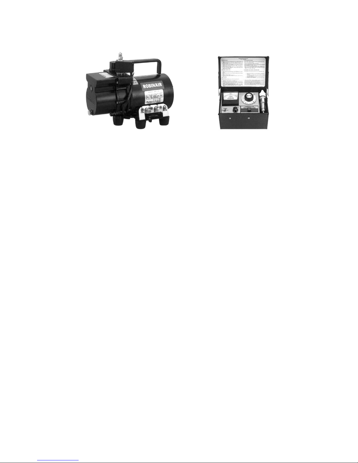
Recommended vacuum gauge : ROBINAIR 14010 Thermistor Vacuum Gauge
1. Vacuum pump with reverse-flow check valve (Photo 1)
To prevent vacuum pump oil from flowing back into the refrigerant circuit upon turning off the vacuum pump’s power
source, use a vacuum pump equipped with a reverse flow check valve.
A check valve may also be added to the vacuum pump currently in use.
2. Standard of vacuum degree (Photos 1 and 2)
Use a vacuum pump that shows a vacuum degree of 65Pa or less after 5 minutes of operation. Use a pump wellmaintained with an appropriate lubricant.
3. Required precision of vacuum gauge
Use a vacuum gauge that registers a vacuum degree of 650Pa and measures at intervals of 130Pa. (A recommended
vacuum gauge is shown in Photo 2.)
Do not use a vacuum gauge that does not register a vacuum degree of 650Pa.
4. Evacuation time
• After the vacuum gauge has registered the vacuum degree of 650Pa, evacuate for 1 hour. (A thorough vacuum drying
removes moisture in the pipes.)
• Verify that the vacuum degree has not risen by more than 130Pa 1 hour after evacuation. A rise by less than 130Pa is
acceptable.
• If it has exceeded by more than 130Pa, conduct vacuuming following the instructions in the “6. Special vacuum drying”
section.
5. Procedures for stopping vacuum pump
To prevent the reverse flow of vacuum pump oil, open the relief valve on the vacuum pump side, or draw in air by
loosening the charge hose, and then stop the operation.
The same procedures should be followed when stopping a vacuum pump with a reverse-flow check valve.
6. Special vacuum drying
• When 650Pa or lower degree of vacuum cannot be attained after 3 hours of evacuation, it is likely that water has
penetrated the system or that there is a leak. When water infiltration is suspected, vacuum with nitrogen gas.
After breaking the vacuum, pressurize the system with nitrogen gas to a degree of 0.05MPa, and conduct an evacuation
again. Repeat it until 650Pa or lower degree of vacuum is attained or the vacuum pressure rise will be lost.
• Only use nitrogen gas for vacuum breaking. (Use of oxygen may cause an explosion.)
Photo 1 15010H Photo 2 14010
- 14 -
[9] Vacuum Drying
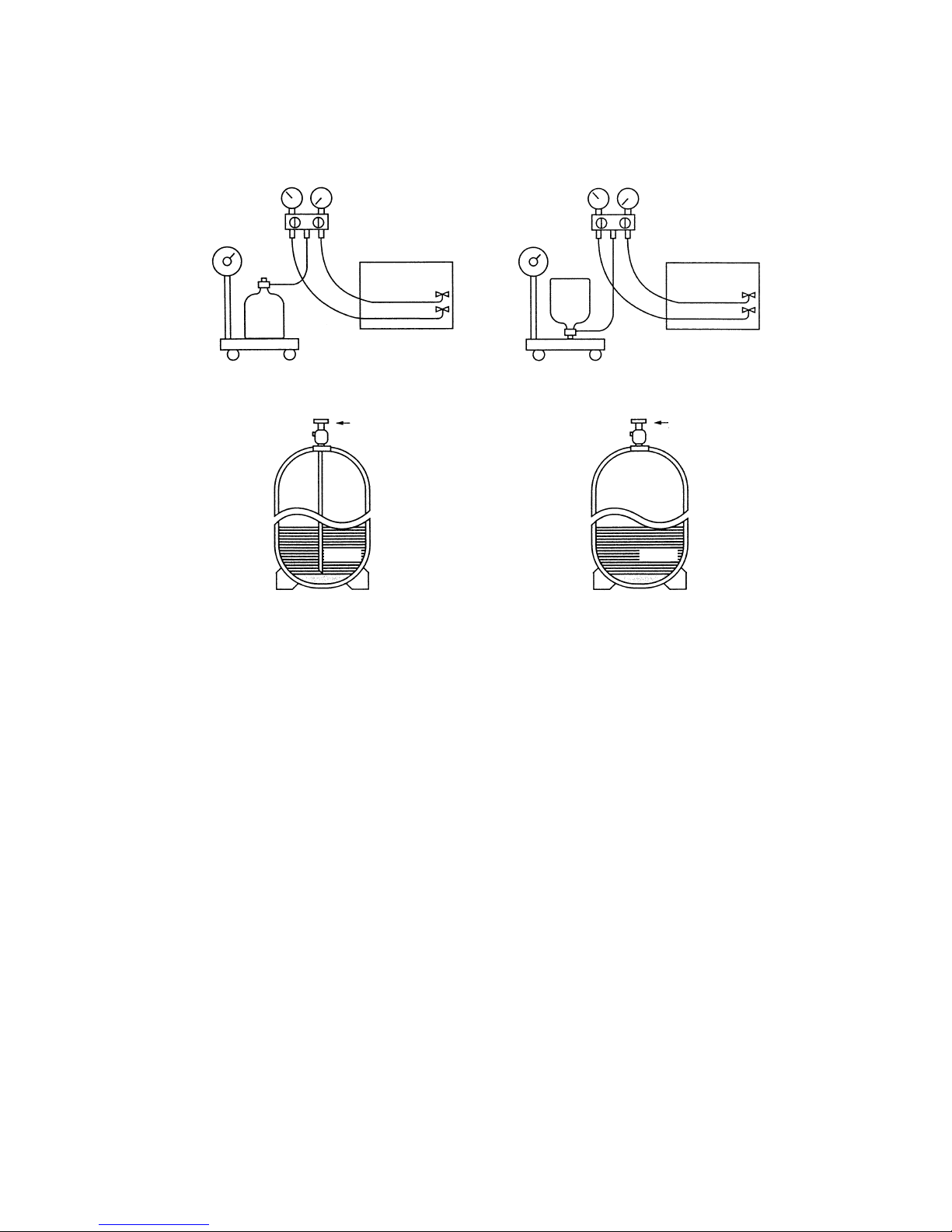
R410A must be in a liquid state when charging.
For a cylinder with a syphon attached For a cylinder without a syphon attached
Cylinder color identification R407C-Gray Charged with liquid refrigerant
R410A-Pink
Reasons :
1.
Note :
• In the case of a cylinder with a syphon, liquid R410A is charged without turning the cylinder up side down. Check the
type of cylinder before charging.
Cylin-
der
Cylin-
der
Valve
Val ve
Liquid
Liquid
R410A is a pseudo-azeotropic refrigerant (boiling point R32 = -52˚C, R125 = -49˚C) and can roughly be handled
in the same way as R22; however, be sure to fill the refrigerant from the liquid side, for doing so from the gas
side will somewhat change the composition of the refrigerant in the cylinder.
When refrigerant leaks, additional refrigerant may be charged. (Add the refrigerant from the liquid side.)
✻Refer to 9-[5].
- 15 -
[10] Changing Refrigerant
[11] Remedies to be taken in case of a refrigerant leak
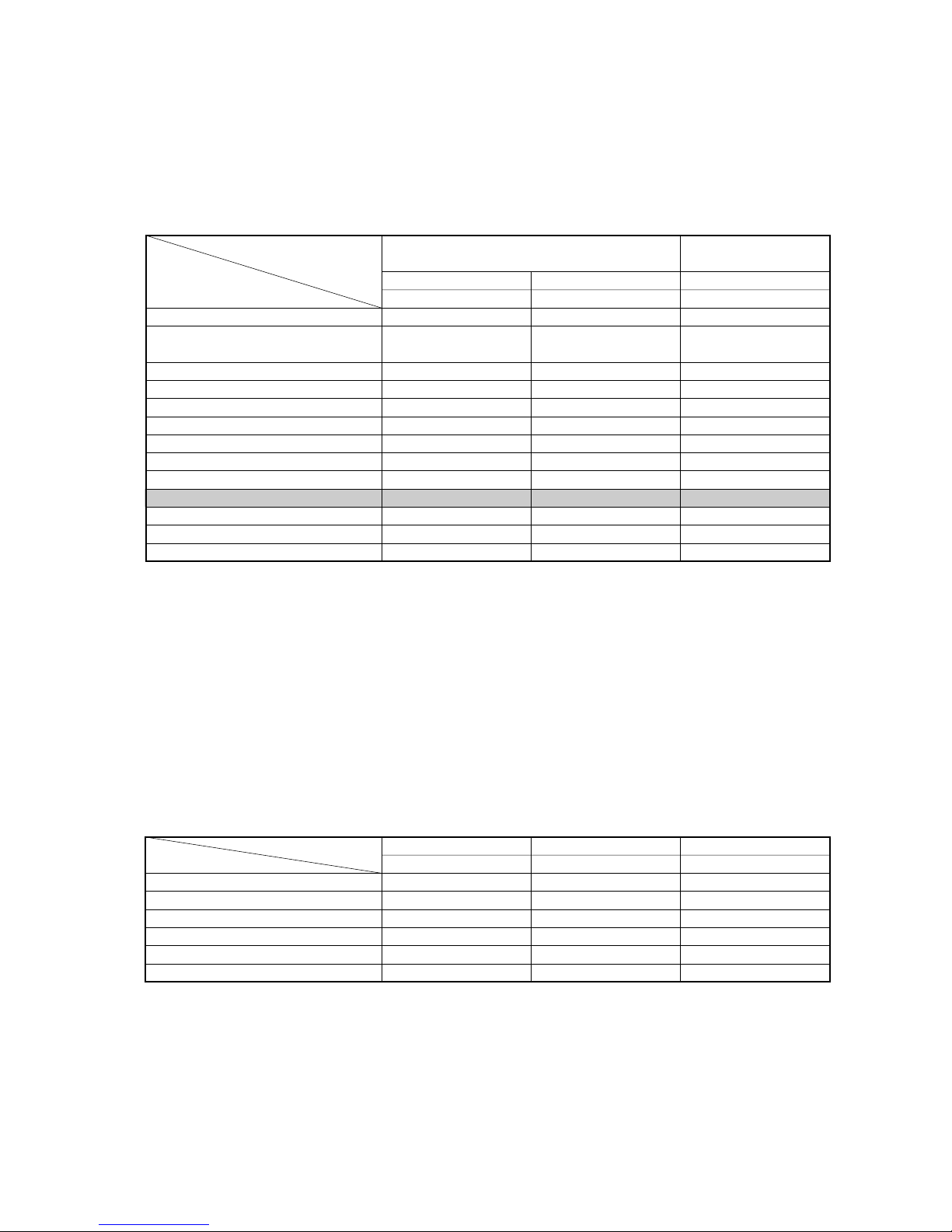
Composition (wt%)
Type of refrigerant
Chloride
Safety Class
Molecular Weight
Boiling Point
Steam Pressure (25
˚C,MPa)(gauge)
Saturated Steam Density (25
˚C,kg/m3)
Flammability
Ozone Depletion Coefficient (ODP)✻1
Global Warming Coefficient (GWP)✻2
Refrigerant charging method
Addition of refrigerant in case of a leak
R410A
R32/R125
(50/50)
Simulated azeotropic
refrigerant
Not contained
A1/A1
72.6
-51.4
1.557
64.0
Non-flammable
0
1730
Liquid charging
Possible
R407C
R32/R125/R134a
(23/25/52)
Non-azeotropic
refrigerant
Not contained
A1/A1
86.2
-43.6
0.9177
42.5
Non-flammable
0
1530
Liquid charging
Possible
New Refrigerant
(HFC system)
Conventional Refrigerant
(HCFC system)
R22
R22
(100)
Single refrigerant
Contained
A1
86.5
-40.8
0.94
44.4
Non-flammable
0.055
1700
Gas charging
Possible
✻1: When CFC11 is used as a reference ✻2: When CO
2 is used as a reference
- 16 -
[12] Characteristics of the Conventional and the New Refrigerants
1. Chemical property
As with R22, the new refrigerant (R410A) is low in toxicity and a chemically stable non-flammable refrigerant.
However, because the specific gravity of steam is greater than that of air, leaked refrigerant in a closed room will
accumulate at the bottom of the room and may cause hypoxia. Also, leaked refrigerant exposed directly to an
open flame will generate noxious gasses. Use the unit in a well-ventilated room.
R410A
MPa
0.30
0.70
1.34
2.31
3.73
4.17
-20
0
20
40
60
65
R407C
MPa
0.18
0.47
0.94
1.44
2.44
2.75
R22
MPa
0.14
0.40
0.81
1.44
2.33
2.60
Pressure (gauge)
Temperature (
˚C)
3. Pressure Characteristics
The pressure in the units that use R410A is 1.6 times as great as that in the units that use R22.
2. Refrigerant Composition
Because R410A is a simulated azeotropic refrigerant, it can be handled in almost the same manner as a single
refrigerant such as R22. However, if the refrigerant is removed in the vapor phase, the composition of the refriger
ant in the cylinder will somewhat change.
Remove the refrigerant in the liquid phase. Additional refrigerant may be added in case of a refrigerant leak.
- 17 -
Refrigerant Refrigerating machine oil
R22
R407C
R410A
Mineral oil
Ester oil
Ester oil
[13] Notes on Refrigerating Machine Oil
1. Refrigerating Machine Oil in the HFC Refrigerant System
HFC type refrigerants use a refrigerating machine oil different from that used in the R22 refrigerant system.
Please note that the ester oil sealed in the unit is not the same as commercially available ester oil.
Cause Symptom
Clogged expansion valve and capillary
Poor cooling performance
Compressor overheat
Poor motor insulation
Motor burning
Coppering of the orbiting part
Locking
Burning in the orbiting part
Expansion valve/capillary
Poor cooling performance
Drier clogging
Compressor overheat
Burning in the orbiting part
Expansion valve and capillary clogging
Poor cooling performance
Compressor overheat
Burning in the orbiting part
Effects on the refrigeration cycle
Sludge formation
Generation of acid
Oxidization
Oil degradation
Water infiltration
Air infiltration
Infiltration
of
contaminants
Dust, dirt
Mineral oil
etc.
Expansion valve and capillary freeze
Hydrolysis
Oxidization
Adhesion to expansion valve and capillary
Infiltration of contaminants into the compressor
Sludge formation and adhesion
Oil degradation
2. Effects of the ✻Contaminants in the System
Refrigerating machine oil used in the HFC system must be handled more carefully than conventional mineral oils.
The table below shows the effects of air, moisture, and contaminants in the refrigerating machine oil on the refrigeration cycle.
✻ “ Contaminants ” is defined as moisture, air, process oil, dust/dirt, the wrong types of refrigerant and refrigerat-
ing machine oil.
<The Effects of Air, Moisture, and Contaminants in the Refrigerating Machine Oil on the Refrigeration Cycle.>
OK NO
➀ Follow ordinance of your governmental organization for technical standard related to electrical equipment, wiring
regulations, and guidance of each electric power company.
➁ Wiring for control (hereinafter referred to as transmission line) shall be (5cm or more) apart from power source wiring so
that it is not influenced by electric noise from power source wiring. (Do not insert transmission line and power source wire
in the same conduit.)
➂ Be sure to provide designated grounding work to outdoor unit.
➃ Give some allowance to wiring for electrical part box of indoor and outdoor units, because the box is sometimes removed
at the time of service work.
➄ Never connect 380~415V(220~240V )power source to terminal block of transmission line.If connected,electrical parts
will be burnt out
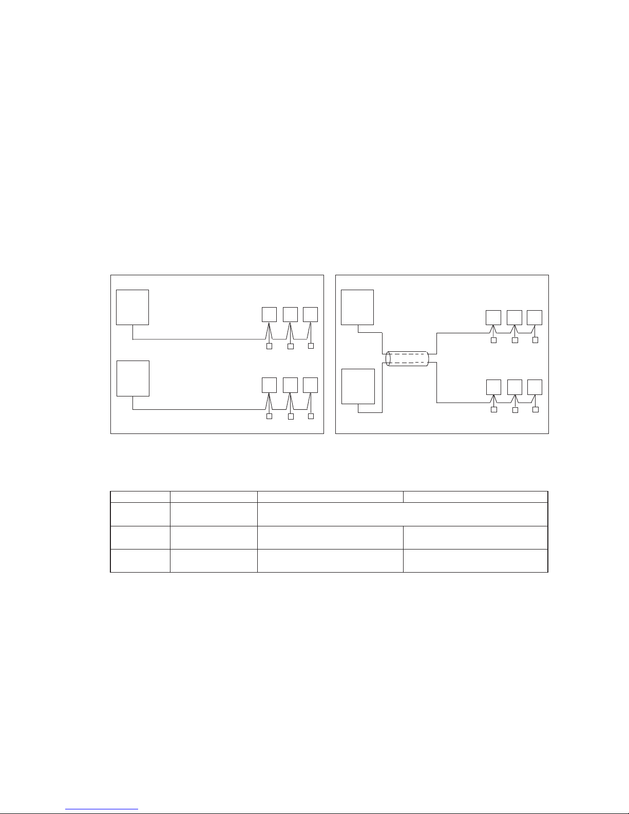
➅ Use 2-core shield cable for transmission line. If transmission lines of different systems are wired with the same multiple-
core cable, the resultant poor transmitting and receiving will cause erroneous operations.
Outdoor
unit
Indoor unit
Remote
controller
2-core cable
2-core cable
Outdoor
unit
Remote
controller
Indoor unit
Multiple-
core cable
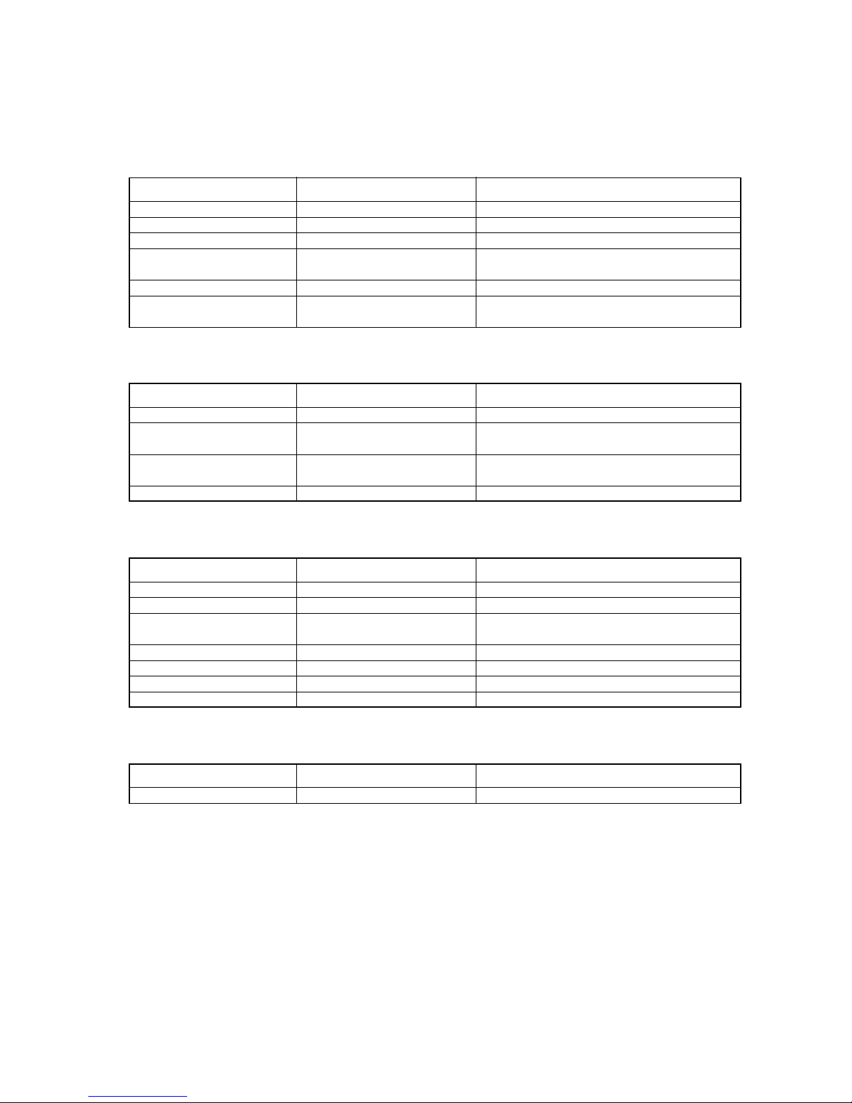
Type of cable
Cable diameter
Remarks
Sheathed 2-core cable (unshielded)
CVV
0.3
~ 1.25mm
2
(0.75 ~ 1.25mm2) ✻1
More than 1.25mm
2
Shielding wire (2-core)
CVVS or CPEVS
When 10m is exceeded, use cables with
the same specification as transmission cables.
0.3 ~ 1.25mm
2
(0.75 ~ 1.25mm2) ✻1
Max length : 200m
Transmission cables M-NET Remote controller cables MA Remote controller cables
CVVS : PVC insulated PVC jacketed shielded control cable
CPEVS : PE insulated PVC jacketed shielded communication cable
CVV : PV insulated PVC sheathed control cable
—
✻
1 Connected with simple remote controller.
- 18 -
™™
Restrictions
[1] Electrical Work & M-NET control
1. Attention
2. Types of control cable
00
00
101
Main
00
201
201
201
202
000
247
Address (1) setting varies depending on the system configuration. See “[3] Examples of system connection”
section for details.
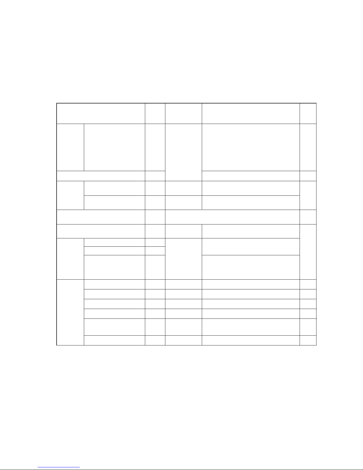
Unit or controller Symbol
Address
Setting method
setting range
Indoor unit Main/sub units IC
Lossnay LC
M-NET
remote
controller
Main remote controller RC
Sub remote controller RC
MA remote controller MA
Outdoor unit OC
System
controller
Group remote controller GR, SC
System remote controller SR, SC
ON/OFF remote controller AN, SC
ST, SCSchedule timer (for M-NET)
Centralized controller TR, SC
(Note 5)
LM adapter SC
0, 01~50
(Note 1)
101~150
151~200
(Note 2)
0, 51~100
(Note 1, 3, 4)
52~100
(Note 3, 4)
201~250
201~250
201~250
201~250
0, 201~250
201~250
Notes:
Factory
setting
Type and method of switch setting
Switch setting vary depending on the system configuration. Make sure to read “[3] Examples of system connection”
before conducting electrical work. Turn off the power before setting the switch. Operating the switch while the unit is
being powered will not change the setting, and the unit will not properly function.
1. Address setting is not required for a single refrigerant system (with a few exception).
2. When setting M-NET remote controller address to “200,” make it “00.”
3. When setting the outdoor unit and outdoor auxiliary unit address to “100,” make it “50.”
4. When an address in a system overlapped with the outdoor unit or BC controller (Main) address of other refrigerant system,
choose an another address within theset range that is not in use (with a few exceptions).
5. When controlling the K-control units;
(1) A K-transmission converter (Model name: PAC-SC25KA) is required. To set the address for the K-transmission converter,
set it to thelowest address of the K-control unit to be controlled + 200.
(2) Set the address of the system controller (G-50A) to “0.” The K-control unit can only be controlled by the system controller
with theaddress “0.”
(3) To control both K-control unit and M-NET model unit, make the address of the K-control unit larger than that of the indoor
unit of M-NET model.
Group-register on the system controller so that the group No. and the lowest address of the K-controlled indoor units
belonging to thegroup will be identical.
Use the address that equals the sum of the smallest indoor
unit address in the same refrigerant system and 50.
Use the address that equals the sum of the smallest
address of the indoor unit out of all the indoor units
that are connected to the BC controller and 50.
When a sub BC controller is connected, the automatic
start up function will not be available.
Auxiliary
units
Hex. unit
BC controller (Sub)
OS
BC
BS
Use the address that equals the sum of the address of the
outdoor unit in the same refrigerant system and 1.
BC controller (Main)
Choose any number within the range of addresses shown left.
However when using with the upper SC setting, or wishing to
control the k-control units, set to “0.”
Assign the smallest address to the indoor unit to
become the main unit within the same group, and
then use sequential numbers to assign an address
to all the indoor units in the group. (Note 5)
If applicable, set the sub BC controllers in an R2
system in the following order:
(1)
Indoor unit to be connected to the main BC controller
(2)
Indoor unit to be connected to No.1 sub BC controller
(3)
Indoor unit to be connected to No.2 sub BC controller
Set the address so that (1) < (2) < (3)
Assign any unused address after setting all indoor units.
Set to the lowest address of the indoor main unit
within the same group + 150.
Set to the lowest No. of the group to be controlled + “200.”
Set to the lowest No. of the group desired tobe controlled + “200.”
Choose any number within the range of addresses shown left.
Choose any number within the range of ad-dresses shown left.
Choose any number within the range of addresses shown left.
Set to the lowest address of the indoor main unit
within the same group + 100.
No address setting required. (When operating with 2 remote controllers,
the main/sub selector switch must be set.
- 19 -
[2] Types of Switch Setting and Address Setting
1. Switch setting
2. Address setting
- 20 -
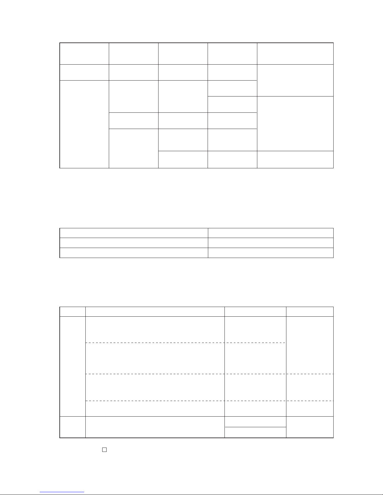
System
Configuration
Single refrigerant
system
___
_
Multiple refrigerant
system
Connection with
the system
controller
Power supply unit
for the
transmission lines
Unnecessary
Unnecessary (Note2)
(Supplied from the
outdoor unit)
Applicable
Grouping operation
of different
refrigerant systems
n/a
applicable
applicable // n/a
applicable // n/a
applicable // n/a
The setting of the power supply
selecting connector
Use CN41 as is (Factory setting)
Replace the CN41 with CN40 on
only one of the outdoor units.
✻
Connect the S terminal of the TB7
(terminal block on the outdoor
unit) on the outdoor unit whose
CN41 was replaced with CN40 to
the earth terminal of the electric
box.
Use CN41 as is (Factory setting)
n/a
Connected with the
indoor units
Connected with the
centralized system
Notes:
1. Will limit the total connectable units in the refrigerant system.
2. The need for a power supply unit for the transmission lines depends on the system configuration. Refer to “ DATA BOOK ” for
more details.
Setting the power supply selecting connector for the outdoor unit (Factory setting: CN41 is connected.)(2)
System configuration Setting of the centralized controller switch (SW 2-1)
Connection system with the system controller n/a Leave it to OFF. (Factory setting)
Connection system with the system controller applicable (Note 1) ON
Note:
1. When connecting only the LM adapter, leave SW2-1 to OFF.
Note:
1.
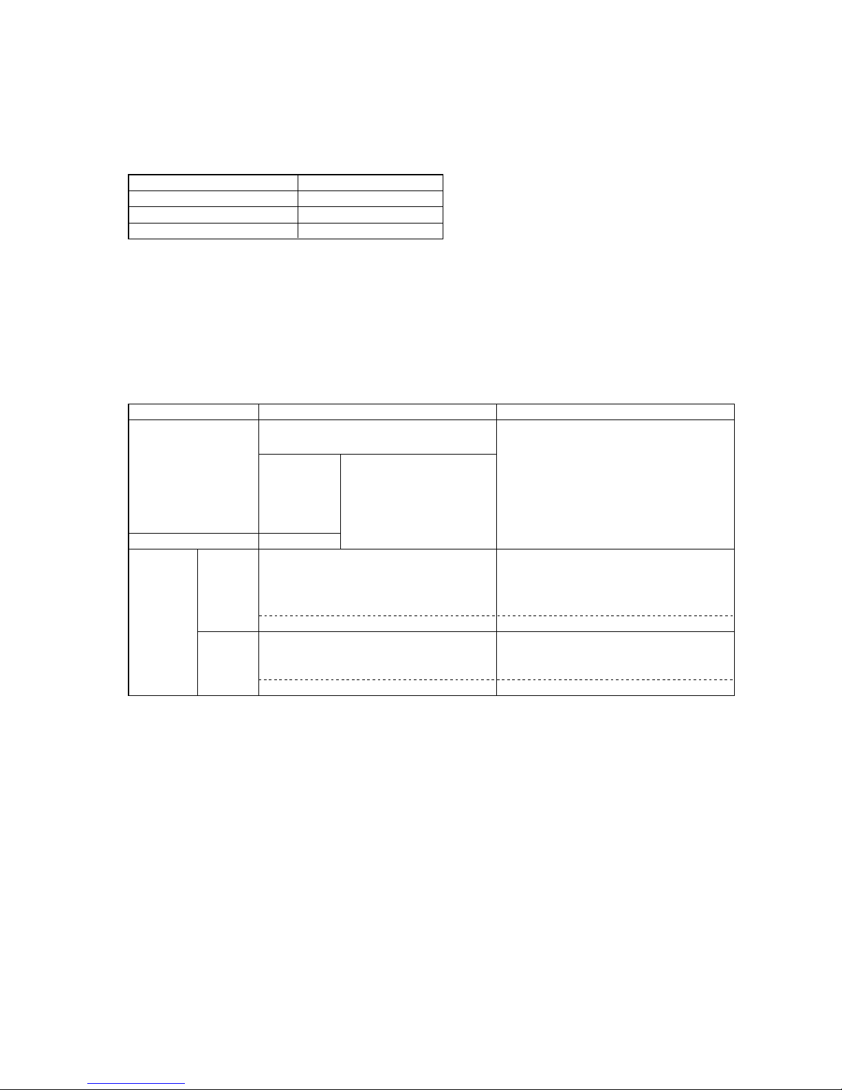
Refer to section “ 7 [2] 12. Demand control ” for detailed information on demand control settings.
Setting the centralized control switch on the outdoor unit (factory setting: SW2-1 OFF )(3)
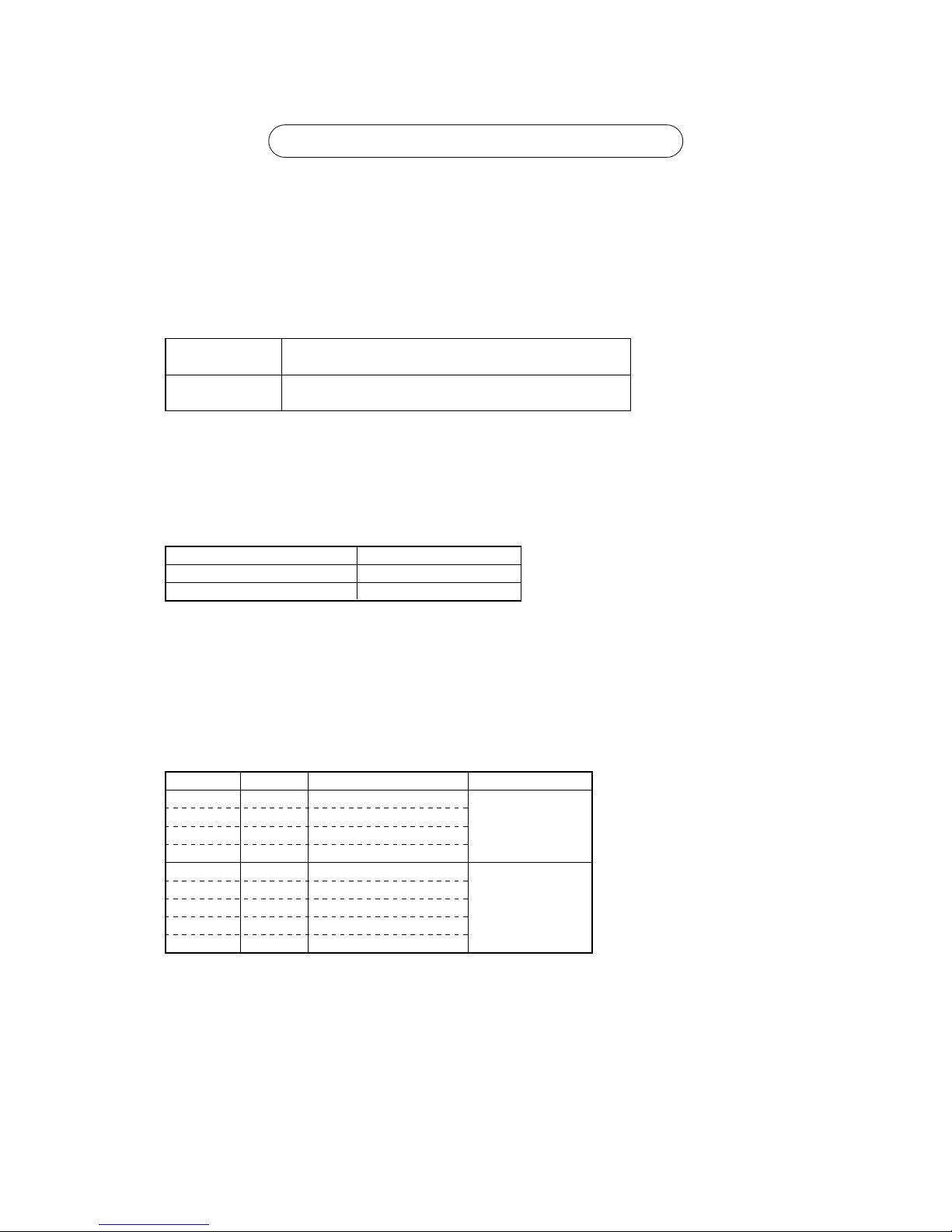
Category
Output
Input
Usage
Cooling operation is disabled (thermo OFF) by the external
input to the outdoor units.
✻ Can be used as an on-demand control for each refrigerant
system.
Quiet operation of outdoor units is run with an external input to
the outdoor units.
(Night mode can be run under the following conditions: Outdoor
air temperature below 30
˚C when running a cooling operation
and above 3˚C when running a heating operation.)
Forces the outdoor units to run a fan operation by receiving the
snow signal from the snow sensor.
The operation mode can be switched between cooling and
heating with an external input to the outdoor units.
Outdoor units’ signal output
✻ Can be used as a device that displays the operation status
✻ Can run an interlocking control operation with external devices
Function
Demand (level)
Night mode or Demand
(Level) ✻
Note1
Snow sensor
Signal input (level)
You can switch the operation mode between cooling and
heating by input from the outside to the outdoor unit.
Auto-changeover
Compressor in operation
Abnormal operation status
CN3S
CN3N
CN3D
CN51
Terminal to be used
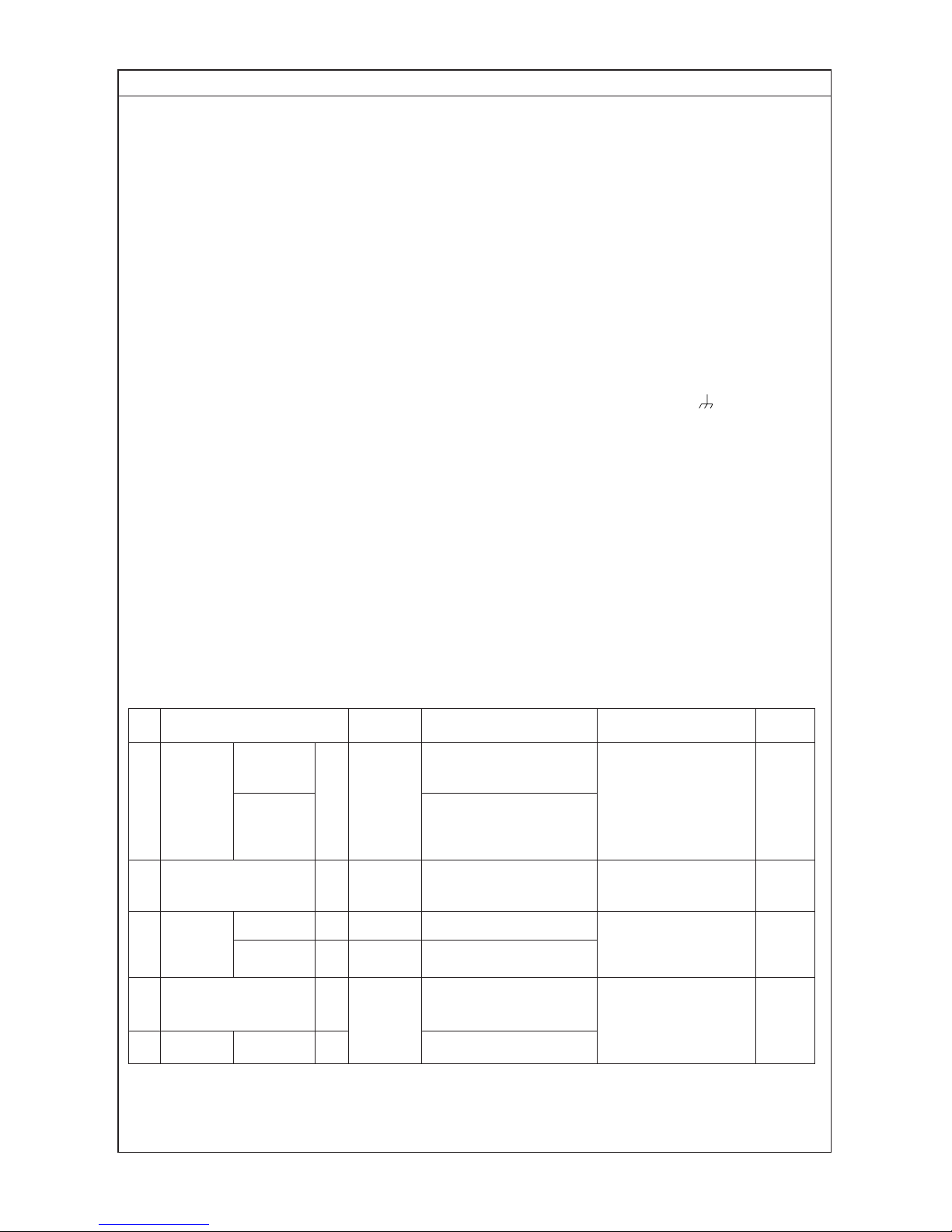
Various types of control using the connectors on the outdoor unit for input-output signal
(various types of connections with optional parts)
(4)
IC
TB5 TB
15
12
00
IC
TB5 TB
15
12
00
A1 B2
MA
A1 B2
MARC
TB5
00
IC
TB5
12
TB
15
IC
TB5 TB
15
12
0000
IC
TB5 TB
15
12
00
A1 B2
MA
A1 B2
MA
A1 B2
MA
MA
m1
L11
m2
L3 L4
L12 L13
m3
m5
m4
NO
NO
L2
OC
TB3
TB7
00
A1 B2
A1 B2
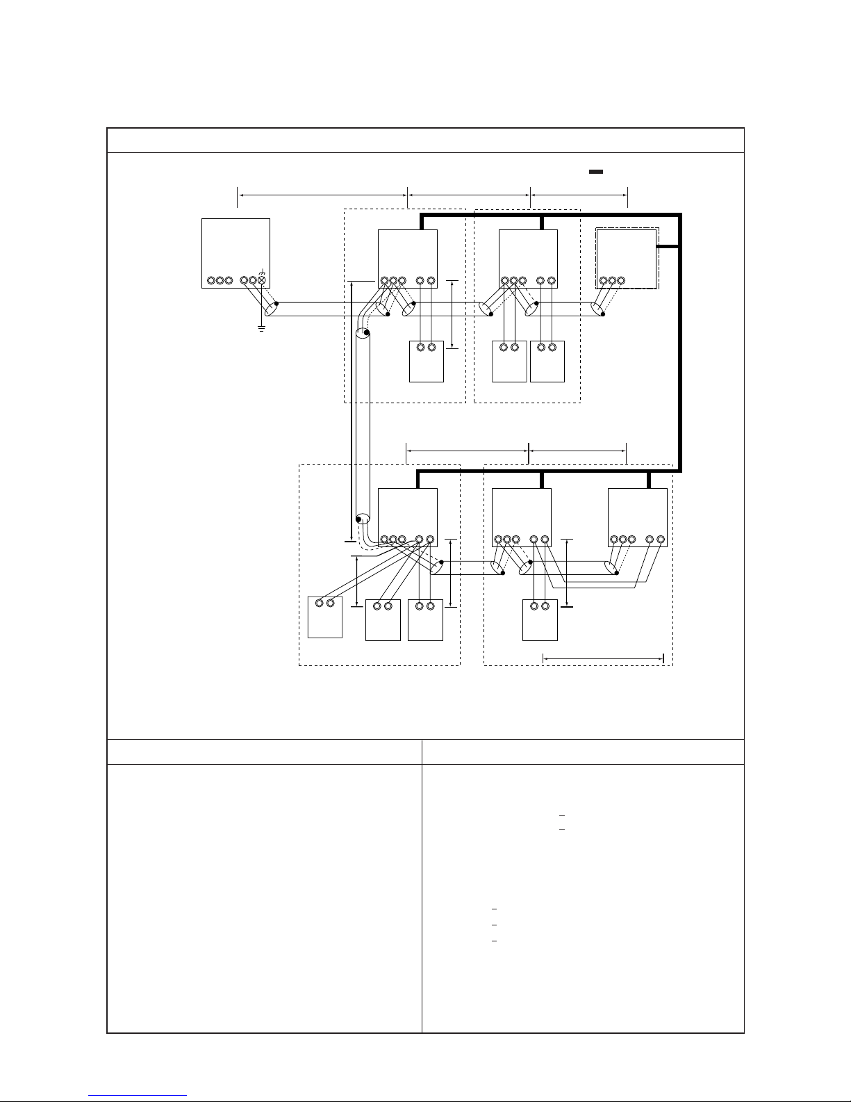
a. Indoor/outdoor transmission line
Farthest length (1.25mm2 or more)
L2 + L3 + L4 200m
L2 + L11 + L12 + L13 200m
b. Centralized control transmission line
No connection is required.
c. MA remote controller wiring
Total length (0.3 ~ 1.25mm2)
m1 200m
m2 + m3 200m
m4 + m5 200m
Note 1. For the connection to the terminal block of compact
remote controller, employ wire with a diameter of 0.75
~ 1.25mm
2
Control wiring example
Group
Prohibited items Allowable length
1. M-NET and MA remote controllers can not be connected together to the indoor unit within the same group.
2. MA remote controller of 3 units or more can not be connected
to the indoor unit within the same group.
3. When the total number of indoor units exceeds 26 units Including that above Type 200, a transmission booster is required.
4. In the case when start/stop input (CN32, CN51, CN41) is used
by indoor group operation, the “Automatic address set-up”
can not be employed. Please refer to 1. (2) “ Manual address
set-up.”
5. For the connection of LOSSNAY with more than 2 units in a
single refrigerant system, refer to the following “Connection
of 2 LOSSNAY units in refrigerant system.”
Interlocking with ventilation
– Example to use shielded wire –
Group
Group
Group
LC
≤
≤
≤
≤
≤
S
M1M2
S
M1M2
S
M1M2
S
M1M2
S
M1M2
S
M1M2
S
M1M2
M1M2
- 21 -
[3] Examples of system connection
1. System using MA remote controller
(1) In the case of single refrigerant system (Automatic address set-up)
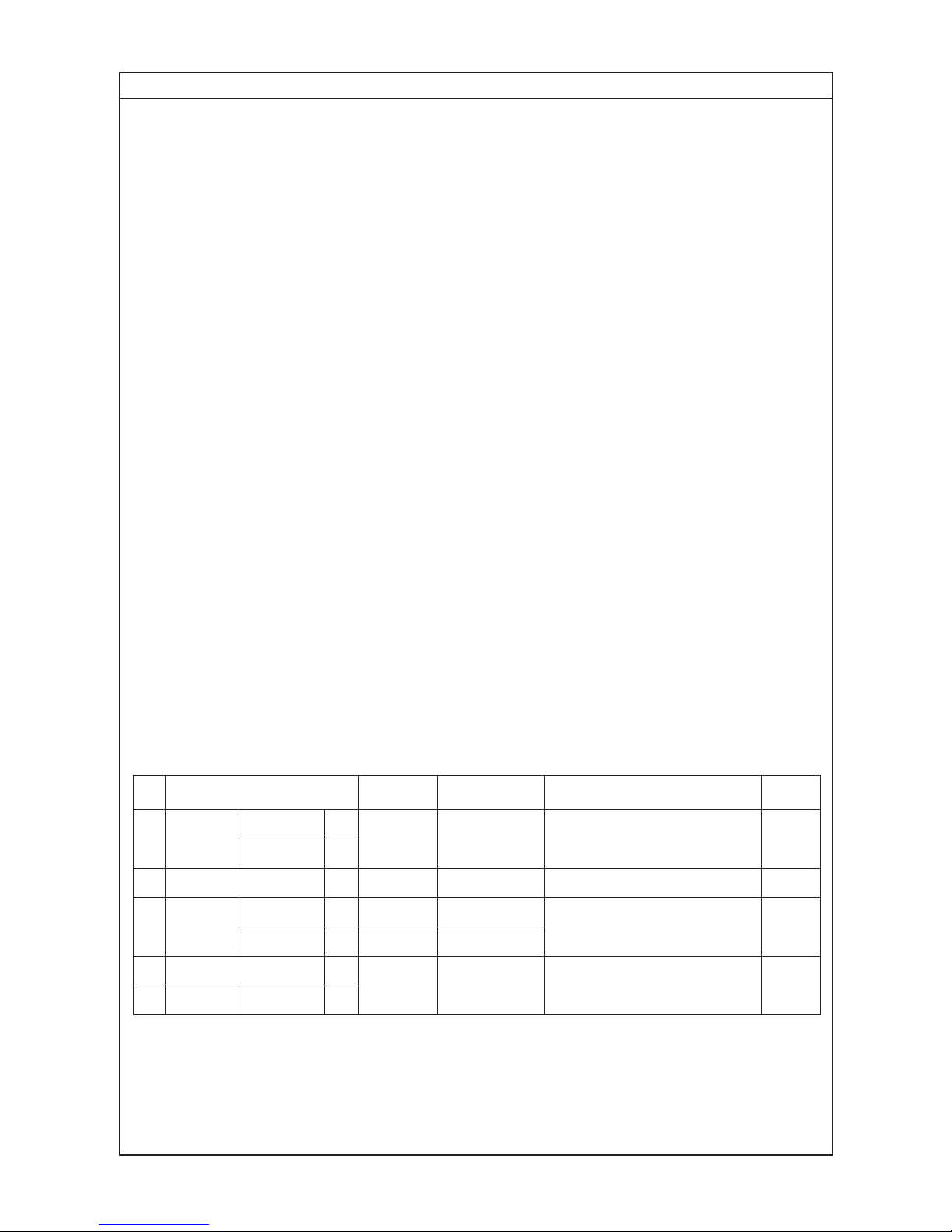
Wiring method • Address setting method
a. Indoor/outdoor transmission line
Apply jumper wiring connection between M1, M2 terminals of the indoor/outdoor transmission line terminal block
(TB3) on the outdoor unit (OC) and that of indoor/outdoor transmission line terminal block (TB5) on each indoor
unit (IC). (with non-polarity two wires)
❉ When the transmission line is long or noise sources are located near the unit, recommend to use shielded wire.
Connection of shielded wire:
For the earth of shielded wire, apply jumper wiring connection between the earth screw of OC and the S-terminal of
IC terminal block (TB5).
b. Centralized control transmission line
Connection is not required.
c. MA remote controller wiring
Connect the 1, 2 terminals of MA remote controller wiring terminal block (TB15) on IC to the terminal block of MA
remote controller (MA). (with non-polarity two wires)
❉ MA remote controller can be connected to A-type indoor unit or later.
For 2-remote controller operation:
To employ 2-remote controller operation, connect 1, 2 terminals of the terminal block (TB15) on IC to the terminal
block of two MA remote controllers.
❉ Set the main/sub selector switch of one MA remote controller to the sub remote controller. (For the setting method,
see the installation manual of MA remote controller.)
For indoor group operation:
For the group operation of IC, connect 1, 2 terminals of the terminal block (TB15) on all ICs within the same group,
and connect 1, 2 terminals of the terminal block (TB15) on another IC to the terminals of MA remote controller.
(with non-polarity two wires)
❉ To operate the indoor units with different function in the same group, refer to 1. (2).
d. LOSSNAY connection
Apply jumper wiring to connect M1, M2 terminals of the terminal block (TB5) on IC to the indoor/outdoor
transmission terminal block (TB5) on LOSSNAY (LC). (with non-polarity two wires)
❉ Linked and registered automatically with all indoor units within a refrigerant system.
❉ Please refer to the 1. (2) “Manual address set-up,” when interlocking partial indoor units with Lossnay, using
Lossnay alone without interlocking, interlocking indoor units and Lossnay for over 16 units within a refrigerant
system, or connecting LOSSNAY for over 2 units in a refrigerant system.
e. Switch setting
Address setting is not required.
Order
Unit or controller
Address
Setting method Caution
Factory
setting range
setting
Main unit IC
Not required – 00
1 Indoor unit
Sub unit IC
2 LOSSNAY LC Not required –
3
MA remote
Main uni
Hex. unit
t MA Not required –
Main
controller
Sub unit MA Sub unit
4 Outdoor unit OC
Not required –
5 Sub unit OS
• Refer to 1. (2) to operate indoor units
with different function in the same
group.
Set with main/sub
selector switch.
00
00
- 22 -
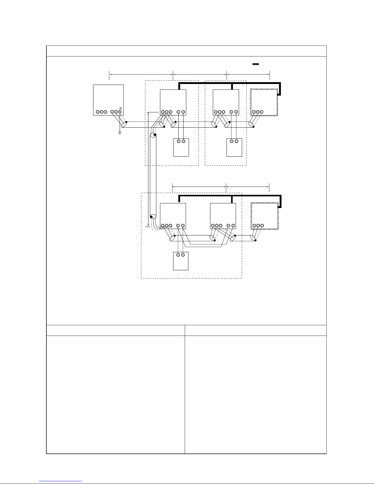
L2
OC
TB3
TB7
51
IC
TB5 TB
15
12
01
IC
TB5 TB
15
12
02
A1 B2
MA
A1 B2
MA
TB5
05
IC
TB5
12
TB
15
IC
TB5 TB
15
12
0403
TB5
06
A1 B2
MA
L11
L3 L4
L12 L13
a. Indoor/outdoor transmission line
The same as 1. (1)
b. Centralized control transmission line
No connection is required.
c. MA remote controller wiring
The same as 1. (1)
Control wiring example
Group
Prohibited items Allowable length
1. M-NET and MA remote controllers can not be connected together to the indoor unit within the same group.
2. MA remote controller of 3 units or more can not be connected
to the indoor unit within the same group.
3. When the total number of indoor units exceeds 26 units including that above Type 200, a transmission booster is required.
Interlocking with ventilation
– Example to use shielded wire –
Group
Group
LC
LC
S
M1M2
S
M1M2
S
M1M2
S
M1M2
S
M1M2
S
M1M2
S
M1M2
M1M2
- 23 -
1. System using MA remote controller
(2) In the case of single refrigerant system connecting 2 or more LOSSNAY units (Manual address set-up)
- 24 -
1 Indoor unit
2 LOSSNAY
3
MA remote
controller
4 Outdoor unit
Main unit
Sub unit
Main uni
t
Sub uni
Hex. unit
t
IC
LC
MA
MA
OC
01 ~ 50
01 ~ 50
Not required
Not required
51 ~ 100
Wiring method • Address setting method
a. Indoor/outdoor transmission line
The same as 1. (1)
Connection of shielded wire:
The same as 1. (1)
b. Centralized control transmission line
No connection is required.
c. MA remote controller wiring
The same as 1. (1)
For 2-remote controller operation:
The same as 1. (1)
For indoor group operation:
The same as 1. (1)
d. LOSSNAY connection
Apply jumper wiring to connect M1, M2 terminals of the terminal block (TB5) on the indoor unit (IC) to the terminal
block (TB5) on Lossnay (LC). (with non-polarity two wires)
❉ The interlocking registration of the indoor unit and Lossnay from the remote controller is required. (For the regis-
tration method, see the installation manual of remote controllers.)
e. Switch setting
Address setting is required as listed below.
Order
Unit or controller
Address
Setting method Caution
Factory
setting range
setting
• Set the lowest address within
a same group to the indoor unit
desired to be the main unit.
Set to the main unit address
within a same group in serial order.
[Main unit +1, +2, +3, .... ]
Set any address after setting al
Set with main/sub selector
switch.
5 Sub unit OS Oundoor unit address + 1
l
indoor units.
–
00
00
Main
00
• When operating indoor
units with different function
within a same group, assign the indoor unit with the
most plenty of function to
the main unit.
• Set the address not to be
overlapped with the indoor
unit address.
• When setting address to
“100,” make it “50.”
The lowest address of indoor
unit within refrigerant system
+ 50
- 25 -
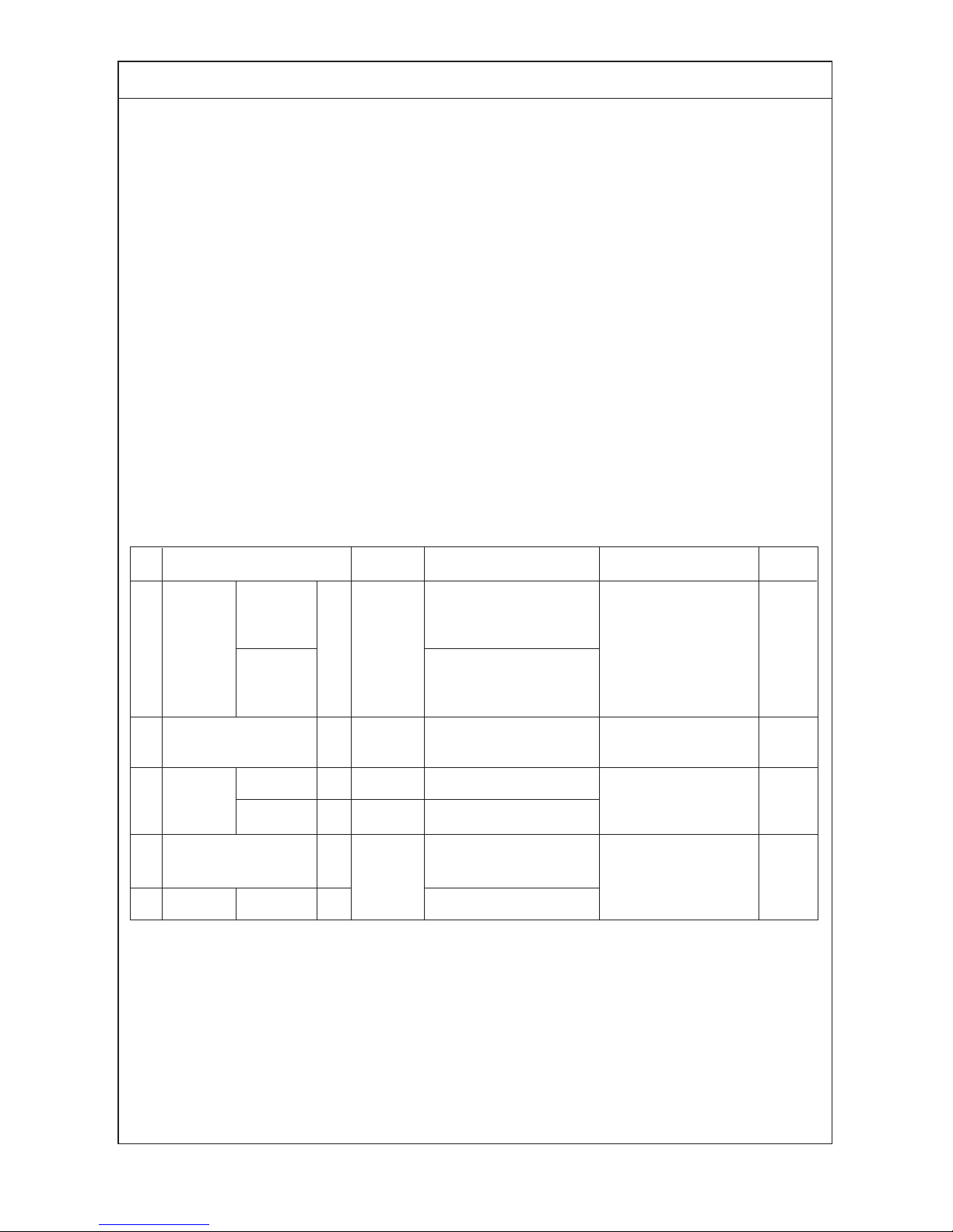
IC
TB5 TB
15
12
01
IC
TB5 TB
15
12
03
A1 B2
MA
A1 B2
MA
TB5
06
IC
TB5
12
TB
15
IC
TB5 TB
15
12 12
0402
IC
TB5 TB15
05
A1 B2
MA
L3 L4
L23 L24
NO
NO
L2
L22
OC
TB3
TB7
51
OC
TB3
TB7
52
L31
m2
m3
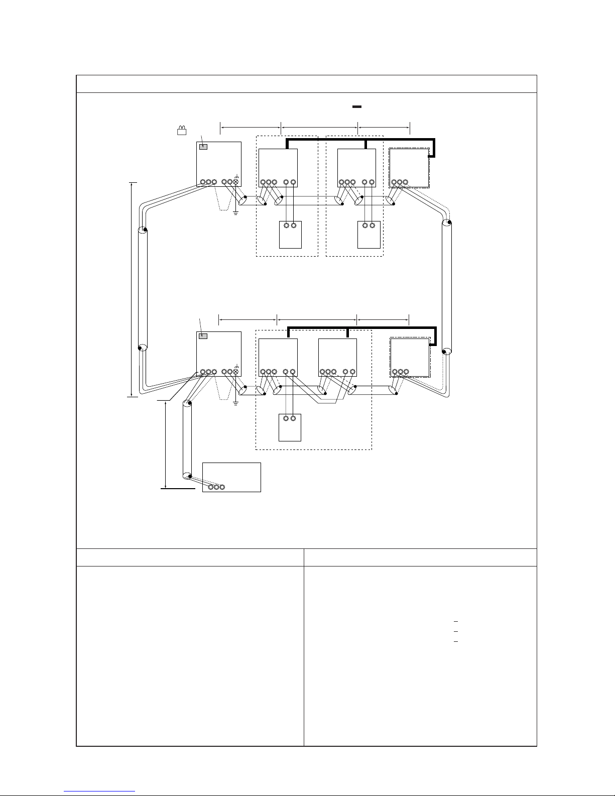
a. Indoor/outdoor transmission line
Farthest length (1.25mm
2
or more)
L2 + L3 + L4 200m
L22 + L23 + L24 200m
b. Centralized control transmission line
Farthest length via outdoor unit (1.25mm
2
or more)
L2 + L3 + L4 + L31 + L22 + L23 + L24 500m
c. MA remote controller wiring
The same as 1. (1)
Control wiring example
Group
Prohibited items Allowable length
1. M-NET and MA remote controllers can not be connected together to the indoor unit within the same group.
2. MA remote controller of 3 units or more can not be connected
to the indoor unit within the same group.
3. Do not connect together the terminal blocks (TB5) of the indoor unit connected to different outdoor units.
4. Replacement of the power supply selecting connector (CN41)
on the outdoor unit should be done only on one outdoor unit.
5. Grounding of S-terminal of the centralized control terminal
block (TB7) on outdoor unit should be done only on one outdoor unit.
6. When the total number of indoor units exceeds 26 units including that above Type 200, a transmission booster is required.
Interlocking with ventilation
– Example to use shielded wire –
Group
Group
LC
Leave CN41
as it is.
Connect
CN41→CN40
Replace
≤
≤
≤
S
M1M2
S
M1M2
S
M1M2
S
M1M2M1M2
S
M1M2
S
M1M2
S
M1M2
S
M1M2M1M2
1. System using MA remote controller
(3) In the case of different refrigerant grouping operation
- 26 -
Wiring method • Address setting method
a. Indoor/outdoor transmission line
Apply jumper wiring connection between M1, M2 terminals of the indoor/outdoor transmission line terminal block
(TB3) on the outdoor unit (OC) and that of indoor/outdoor transmission line terminal block (TB5) on each indoor
unit (IC). (with non-polarity two wires)
❉ Make sure to use shielded wire.
Connecting of shielded wire:
The same as 1. (1)
b. Centralized control transmission line
Apply jumper wiring between M1, M2 terminals of centralized control transmission line terminal blocks (TB7) on
each OC. For one OC only, replace the power selecting connector (CN41) with (CN40).
❉ Make sure to use shielded wire.
Connecting of shielded wire:
Apply jumper wiring to connect the shielded earth to S-terminal of the terminal block (TB7) on each OC. Connect
Sterminal of the terminal block (TB7) on the one OC with (CN40) replaced to the earth screw ( ) of the electrical
parts box.
c. MA remote controller wiring
The same as 1. (1)
For 2-remote controller operation:
The same as 1. (1)
For indoor unit group operation:
The same as 1. (2)
d. LOSSNAY connection
The same as 1. (2)
e. Switch setting
Address setting is required as follows.
1 Indoor unit
2 LOSSNAY
3
MA remote
controller
4 Outdoor unit
Main unit
Sub unit
Main unit
Sub unit
IC
LC
MA
MA
OC
01 ~ 50
01 ~ 50
Not required
Sub unit
51 ~ 100
• Set the address not to be
overlapped with the indoor
unit address.
• When setting address to
“100,” make it “50.”
Order
Unit or controller
Address
Setting method Caution
Factory
setting range
setting
• Set the lowest address within
a same group to the indoor unit
desired to be the main unit.
Set to the main unit address
within a same group in serial order.
[Main unit +1, +2, +3, .... ]
Set any address after setting all
indoor units.
–
Set by the main/sub selector
switch.
The lowest address of indoor
unit within refrigerant system
+ 50
00
00
Main
Hex. unit5 Sub unit OS Oundoor unit address + 1
00
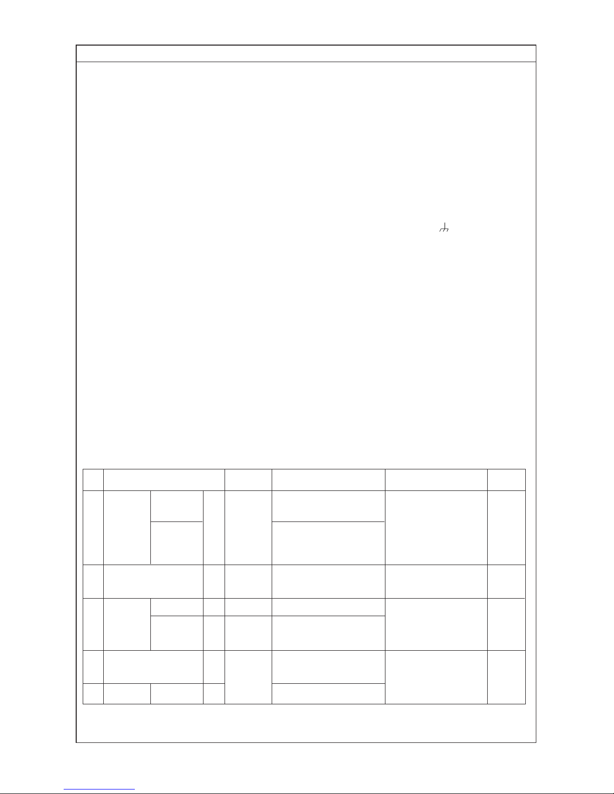
- 27 -
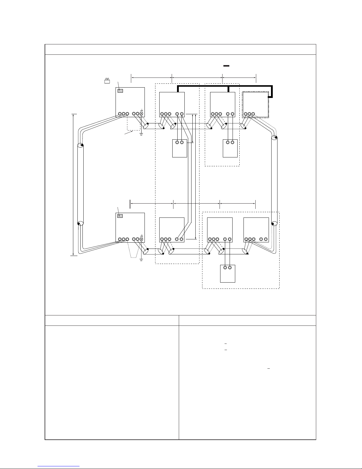
IC
TB5 TB
15
12
01
IC
TB5 TB
15
12
02
A1 B2
MA
A1 B2
MA
TB5
05
IC
TB5
12
TB
15
IC
TB5 TB
15
12
0403
TB5
06
A1 B2
MA
L3 L4
L23 L24
NO
L2
L22
OC
TB3
TB7
51
OC
TB3
TB7
53
ABS
L31
L32
NO
a. Indoor/outdoor transmission line
The same as 1. (3)
b. Centralized control transmission line
Farthest length via outdoor unit (1.25mm2 or more)
L32 + L31 + L2 + L3 + L4 500m
L32 + L22 + L23 + L24 500m
L2 + L3 + L4 + L31 + L22 + L23 + L24 500m
c. MA remote controller wiring
The same as 1. (1)
Control wiring example
Group
Prohibited items Allowable length
1. M-NET and MA remote controllers can not be connected together to the indoor unit within the same group.
2. MA remote controller of 3 units or more can not be connected
to the indoor unit within the same group.
3. Do not connect together the terminal blocks (TB5) of the indoor unit connected to different outdoor units.
6. When the total number of indoor units exceeds 26 units Including that above Type 200, a transmission booster is required.
Interlocking with ventilation
– Example to use shielded wire –
Group
Group
LC
LC
Notes:
1. Leave SW2-1 as “OFF” when connecting LM adapter only.
2. LM adapter requires the power source of 1-phase AC 230V.
Note 1
Note 1
Note 2
System controller
≤
≤
≤
4. Replacement of the power supply selecting connector (CN41)
on the outdoor unit should be done only on one outdoor unit.
5. Grounding work is required for S-terminal of the centralized
control transmission block (TB7) on one outdoor unit only.
CN41→CN40 Replace
SW2-1 OFF→ON
Leave CN41 as it is.
SW2-1 OFF→ON
S
M1M2
S
M1M2
S
M1M2
S
M1M2M1M2
S
M1M2
S
M1M2
S
M1M2
S
M1M2M1M2
1. System using MA remote controller
(4) In the case of connecting system controller to centralized control transmission line
- 28 -
Wiring method • Address setting method
a. Indoor/outdoor transmission line
The same as 1. (3)
Connection of shielded wire:
The same as 1. (1)
c. MA remote controller wiring
The same as 1. (1)
For 2-remote controller operation:
The same as 1. (1)
For indoor group operation:
The same as 1. (1)
d. LOSSNAY connection
Apply jumper wiring to connect M1, M2 terminals of the terminal block (TB5) on (IC) to the terminal block (TB5)
on the indoor/outdoor transmission line terminal block (TB5) on Lossnay (LC). (with non-polarity two wires)
❉ The interlocking registration of the indoor unit and LOSSNAY from the system controller is required. (For the
registration method, see the installation manual of the system remote controllers.)
When connecting ON/OFF remote controller and LM adaptor only, the interlocking registration from the remote
controller is required.
e. Switch setting
Address setting is required as listed below.
1 Indoor unit
2 LOSSNAY
3
MA remote
controller
4 Outdoor unit
Main unit
Sub unit
Main unit
Sub unit
IC
LC
MA
MA
OC
01 ~ 50
01 ~ 50
Not required
Sub unit
• Set the address not to be
overlapped with the indoor
unit address.
• Conduct initial setting by the
system controller with the
same setting detail of indoor
unit applied in MA remote
controller wiring.
• When setting address to
“100,” make it “50.”
Order
Unit or controller
Address
Setting method Caution
Factory
setting range
setting
• Set the lowest address within
a same group to the indoor unit
desired to be the main unit.
Set to the main unit address
within a same group in serial order.
[Main unit +1, +2, +3, .... ]
Set any address after setting all
indoor units.
–
Set by the main/sub selector
switch.
The lowest address of indoor
unit within refrigerant system
+ 50
00
00
Main
b. Centralized control transmission line
Apply jumper wiring between M1, M2 terminals of centralized control transmission line terminal blocks (TB7) on
each OC. On one OC only, replace the power selecting connector (CN41) with (CN40). Set the centralized control
switch (SW2-1) on the main board of all outdoor units to “ON.”
❉ Make sure to use shielded wire.
Connection of shielded wire:
Apply jumper wiring to connect the shielded earth to S-terminal of the terminal block (TB7) on each OC. Connect S-
terminal of the terminal block (TB7) on one OC with (CN40) connected to the earth screw ( ) of the electrical
parts box.
51 ~ 100
Hex. unit5 Sub unit OS Oundoor unit address + 1
00
 Loading...