

Page 1
Service Handbook
2004
AIR CONDITIONERS CITY MULTI
HEAD OFFICE: MITSUBISHI DENKI BLDG., 2-2-3, MARUNOUCHI, CHIYODA-KU, TOKYO 100-8310, JAPAN
Issued in Mar. 2004 MEE03K220
Printed in Japan
New publication, effective Mar. 2004
Specifications subject to change without notice
Service Handbook Replace Multi PUHY-P200·250YREM-A
Page 2

Caution to REPLACE MULTI Installation Work
Flow of installation work in the field Items to be observed
•Please note that our Corporation is not liable to the reliability of existing piping,
wiring and power system for reuse (in relation with the gas leak of piping, partially
defective/disconnection of wiring, deteriorated insulation, characteristic faults due
to worn out system).
•For limitation on the refrigerant piping and applicable piping diameter, check the
existing piping for reuse in accordance with the specified check sheet by referring products catalogs and manuals for judgement to reuse.
•If vapor condensation was found in the past, check the thermal insulation.
•For a portion suffered by condensation dripping, check the deterioration of the
insulation, and repair the insulation materials if required.
•When the copper piping is seriously deteriorated, do not use parts with verdigris
or black spots.
•For reusing the existing control wiring between the outdoor unit, and remote controller, check the wire type , siz e or the lik e based on the chec k sheet to judge the
possibility.
•Even when the above does not meet the item on the check sheet, existing wiring
may be reused depending on the number of connecting indoor units and piping
length. Ask us for detail.
•For the power source system, employ the voltage and number of phase meeting
the outdoor unit, indoor unit and heat storage unit, and adopt the breaker capacity and wiring size based on the power source wiring connection diagram.
•When the existing power source system (including the power source wiring) is
used, check the system for deterioration and damages.
•Check the refrigerating machine oil used in the existing system. (As is found at
the oil inspection, if the refrigerating machine oil used in the existing system is
mineral oil, use the ester oil sampling kit for inspection.
•When the length of piping for reuse is unknown, additional refrigerant charge is
to be calculated based on the quantity of recovered refrigerant. For this reason,
you are kindly requested to recover all refrigerant inside the existing outdoor/
indoor units and extended piping to check and record the quantity. (The standard of additional refrigerant is (Quantity of R22 recovered - Charged quantity of
existing outdoor unit + 3kg). Adjust the refrigerant quantity after mineral oil recovery operation.)
■ Outdoor unit
•Confirm the space around the outdoor unit.
(Verifying the installation space of the oil trap kit)
■ Turn the power source on, and confirm the normality of the system
•Check the remote controller or outdoor unit for error display.
•Run the indoor unit for fan operation after turning the remote controller on, and
check the air feeding and direction.
Do not run the compressor until finishing the mineral oil recovery operation.
■Mount the valve to the field piping (extended piping). (The ball valve is being
attached to the outdoor unit.)
■Execute an airtight test to check the existing piping for deterioration or leaking.
■Calculate the quantity required by the extended piping, and charge the addi-
tional refrigerant. Make sure to enter the value in the additional refrigerant charge
column on the label of combined outdoor unit being pasted on the outdoor unit.
Without applying any operation, keep the ball v alves of the outdoor unit c losed
before mineral oil recovery operation.
It is necessary to charge refrigerant in a rated quantity and adjust the quantity.
Be sure to execute when the piping length is unknown.
For detail, consult the agent of your dealer.
Enter required items in the request form of REPLACE MULTI mineral oil recovery work.
During local installation work
Before local installation work
Confirming the possibility of existing
refrigerant piping for reuse
Confirming the possibility of existing
control wiring for reuse
Confirming the possibility of existing
power source system for reuse
Confirming the objective range for
replacing
Recovering the refrigerant of old system
Removing the outdoor/indoor units, remote controllers, etc.
Installing the outdoor/indoor units, remote
controllers, etc., and executing electrical
work
Setting the address, checking the system
Executing the piping work (mounting of
ball valve).
Air tightening and evacuating the existing
piping and charging refrigerant
Operating mineral oil recovery
Executing test run and adjustment (for
final verification of operation).
Page 3

Safety Precautions
• Before installing the unit, make sure you read all the “Safety precautions”.
• The “Saf ety precautions” provide very important points regarding safety. Make sure you f ollo w
them.
Symbols used in the text
Warning:
Describes precautions that should be observed to prevent danger of injury or death to the user.
Caution:
Describes precautions that should be observed to prevent damage to the unit.
Symbols used in the illustrations
: Indicates an action that must be avoided.
: Indicates that important instructions must be followed.
: Indicates a part which must be grounded.
: Beware of electric shock (This symbol is displayed on the
main unit label.) <Color: Yellow>
Warning:
Carefully read the labels affixed to the main unit.
Warning
Ask your dealer or specialized contractor for
installation.
•If your own installation work is improper, fire, electric
shock or water leakage may result.
Connect wiring using the specified cable and fasten it securely to prevent the external force of
the cable from being transferred to the terminal
connecting sections.
• Improper connection or fastening may cause heat
generation or fire.
Conduct specified installation work durable
against strong winds around buildings.
•Improper installation work can cause trouble i.e. the
unit toppling over.
Never attempt to repair the unit. For repair,
ask your dealer.
•Improper repair may result in water leakage, electric
shock or fire.
Do not touch the heat exchanger fins.
•Improper handling may cause cuts.
When refrigerant gas is leaked during work,
conduct ventilation.
•If refrigerant gas comes into contact with fire, it may
cause the generation of poisonous gases.
Please conduct correct installation work by
observing this Installation Manual.
•Improper installation work may result in water leakage, electric shock or fire.
Conduct all electrical work by a licensed engineer according to “Technical Standard relating to Electrical Facility,” “Wiring Regulation of Power Company,” and instructions in
this Manual, and always use an exclusive circuit.
•Insufficient power source capacity or improper installation may cause electric shock or fire.
When installing or moving the unit, do not
charge other than the specified refrigerant
(R407C) into the refrigeration cycle.
•Air if mixed generates abnormally high pressure inside the refrigeration cycle which may damage the
unit.
Do not reconstruct or reset the protection
devices.
•If the protection devices like the pressure switch or
thermal switch is forcibly operated by short circuiting, or parts other than that specified by Mitsubishi
Electric are used, fire or explosion may be caused.
Page 4

Precautions for Devices that Use R407C Refrigerant
Caution
Use refrigerant piping made of phosphorus
deoxidized copper and copper alloy seamless pipes and tubes. In addition, be sure
that the inner and outer surfaces of the pipes
are clean and free of hazardous sulphur, oxides, dust/dirt, shaving particles, moisture,
or any other contaminant.
•Contaminants on the inside of the refrigerant piping
may cause the refrigerating machine oil to deteriorate.
Store the piping to be used during installation indoors and keep both ends of the piping sealed until just before brazing. (Store
elbows and other joints in a plastic bag.)
•If dust, dirt, or water enters the refrigerant cycle,
deterioration of the oil and compressor trouble may result.
Use ester oil, ether oil or alkylbenzene (small
amount) as the refrigerating machine oil to
coat flares and flange connections.
•The refrigerating machine oil will degrade if it is mixed
with a large amount of mineral oil.
Use liquid refrigerant to seal the system.
•If gas refrigerant is used to seal the system, the composition of the refrigerant in the cylinder will change
and performance may drop.
Do not use other refrigerant other than
R407C.
•Use of other refrigerants (R22 for example) may deteriorate refrigerating machine oil due to chlorine
generation.
Use a vacuum pump with reverse flow protection.
•Otherwise the vacuum pump oil will reversely flow
into the refrigerant circuit causing the possible deterioration of the refrigerating machine.
Do not use the following tools used for conventional refrigerant.
(Gauge manifold, Charging hose, Gas leak
detector, Reverse flow protector, Cap for refrigerant charge, Refrigerant recovery device)
•Mixing of conventional refrigerant /refrigerating machine oil may cause to deteriorate the refrigerating
machine oil.
•Mixing with water may cause deterioration of the refrigerating machine oil.
•As this refrigerant does not contain chloride, the gas
leak detector for conventional refrigerant gas can not
be used.
Do not use a charging cylinder.
•Use of a charging cylinder changes the composition
of refrigerant resulting in possible performance deterioration.
More careful management is required for the
tools than that for the conventional.
•Dust, trash or water content if mixed into the refrigerant circuit may cause to deteriorate the refrigerating machine oil.
Caution to Equipment Used for Replacing
Caution
Do not operate any valves before conducting mineral oil recovery operation.
Operating valves before conducting mineral oil recovery operation may cause a deterioration in the performance of mineral oil recovery.
For mineral oil recovery operation, the system controller and MA remote controller may
be required to be remove sometimes.
• Improper handling can lead to an inability to perform
oil recovery operation.
• For removal, follow the instruction displayed on the
PC for mineral oil recovery.
• Mount the controllers again after finishing the oil recovery operation.
Observe a safe distance from the indoor unit
fan which runs during the mineral oil recovery operation.
Working in the surrounding of the indoor unit fan can
cause personal injury.
Record the quantity of refrigerant replenished.
(Enter into the column for replenished refrigerant
quantity on the label of the indoor unit.)
• Missing the description may deteriorate the performance of mineral oil recovery.
• Malfunction or poor cooling/heating may also be
caused.
During the mineral oil recovery operation, an
error display may be shown on the remote
controller or system controller.
• When an error display was shown during mineral oil
recovery operation, reset the error display after finishing the operation.
To conduct the refrigerant recovery/evacuation of the inside of exiting piping, choose
tools only used with R407C e.g. charging hose.
• Using a charging hose for R407C causes it to mix
the conventional refrigerating machine oil leading to
the deterioration of refrigerating machine oil.
Page 5
Before Conducting Installation Work/Electrical Work
Caution
Do not install the unit at a place where combustible gas can possibly be generated.
•Leaked combustible gas if stagnated around the unit
may cause explosion.
Do not use the unit in a special atmosphere.
•Use in an atmosphere containing high levels of oil,
steam or sulfide gas may seriously degrades the performance or damage parts.
Do not install the unit on a material which is
not designed to be wet.
•If liquid drips from the oil trap kit, apply centralised
drainage work to the oil trap kit.
Apply grounding work securely.
• Do not connect the grounding line to gas pipe, city
water pipe, lightning rod or telephone grounding line.
Improper grounding may cause electric shock.
For the power source wiring, refrain from
giving tensile force to the wiring.
• Disconnection, heat generation or fire may be
caused.
Make sure to mount a leak breaker to the
power source.
• Otherwise electric shock may be caused.
Be sufficiently careful in transporting products.
•Do not transport a product with a weight exceeding
20kg by a single person.
•Some products are packed with PP band. Do not
use it as a means of transporting.
•During transport cuts may be caused by the fin surface of the heat exchanger , please refrain from touching it without gloves.
Do not use the same switch or the like for
plural outdoor units.
Otherwise, malfunction, heat generation or fire may
be caused.
When installing the unit in hospitals or communication equipment plants, prepare measures to prevent noise generation beforehand.
•The noise may cause the erroneous operation or
failure and may giv e negative effect to medial equipment or communication equipment to disturb medical treatment on human bodies or hinders image
broadcasting or generates noise.
Check possibility for the reuse of existing
refrigerant piping by observing this manual.
• The conventional refrigerating machine oil is con-
tained inside existing piping and some residual oil
deteriorates oil recovery performance which may
lead to the deterioration of refrigerating machine oil.
• The piping specification (diameter, length , height
difference) out of the use specified range may hinder
the mineral oil recovery performance, possibly leading to deterioration of refrigerating machine oil.
Do not use breakers or fuses other than that
with correct capacities.
•Use of a fuse with excessively large capacity or wire/
copper wire may cause troubles or fire.
For the power source wiring, use wire with
rated current capacity.
• Otherwise an electric leak, heat generation or fire
may be caused.
When using existing wiring (for power source
or transmission) or switches, check them for
disconnection and deterioration beforehand.
• Otherwise an electric leak, heat generation or fire
may be caused.
Dispose the packing materials properly.
• As the packing materials are using metal products
or wooden pieces such as nails, nail wounds may
be caused if it is improperly treated. Please observe
caution to avoid this from occuring.
•Dispose the polyethylene bag for packing only after
tearing. Otherwise a suffocation accident may be
caused by children play with the disposed bag.
Be sure to mount the valve to the field piping
(extended piping).
After mineral oil recovery, the oil trap kit can not be
removed disabling air conditioning operation.
Provide thermal insulation to the valve on the
field piping (extended piping) properly.
• Insufficient thermal insulation generates condensation that may cause to deteriorate the performance.
• Provide thermal insulation (including lagging) after
recovering mineral oil.
Page 6

Before Conducting Mineral Oil Recovery Operation
Caution
Turn the power source on 12 hours or more
before starting operation.
• Otherwise trouble may be caused. Do not turn the
power off during the operating season.
Do not operate the unit without the panels or
guard.
• Touching the rotating parts, high temperature parts
or high voltage may cause personal injury such as
burns or electric shock.
Do not operate switches with wet fingers.
• Electric shock may be caused.
Do not turn off the power source immediately
after stopping.
• Be sure to wait for 5 minutes or more. Otherwise
water leakage or troubles may be caused.
Do not touch the refrigerant piping during
operation or immediately after stopping with
bare hands.
• The refrigerant piping or the refrigerant circuit parts
of the compressor during operation or immediately
after stopping may have low or high temperature.
Touching with bare hands may cause a burn or frostbite.
Do not run the outdoor unit during a test run until
finishing the mineral oil recovery operation.
• The indoor unit fan will run.
Caution to Mineral Oil Recovery Operation
Warning
Caution
Be sufficiently careful to avoid the oil trap
kit, falling or toppling over.
• If this happens the oil trap kit may be damaged and
refrigerant piping may malfunction.
• Falling down during flushing operation causes the
leak of refrigerant from the joint which is dangerous
if contacts it human body.
After flushing operation, check the residual pressure inside the oil trap kit with a pressure gauge.
If the residual pressure is exceeding 0.294MPa,
recover refrigerant inside the oil trap kit to reduce
the pressure to within 0.2 ~ 0.294MPa.
• Under high inner pressure, pressure rises during
storing, inducing a dangerous situation.
• Under low inner pressure, water content or foreign
matter enters during storing, causing corrosion to
the oil trap kit which may cause troubles.
Be careful not to expose the oil trap kit unit
(especially electrical parts) to rain water.
• The electrical parts if wet with rain water may cause
machine trouble.
• The electrical parts if wet with rain water may cause
electrical shock.
Conduct oil recovery from the oil recovery service valve outdoor or at a place with good ventilation. Use leather gloves when opening the oil recovery service valve and open it slowly.
• If done in a closed space, suffocation can be caused.
• Opening the oil recovery service valve fully and
quickly allows oil to splash, which is dangerous.
• As the oil recovered is of low temperature, frostbite
may be caused if it touches skin.
When the oil trap kit is transported while lying sideways, do not place any thing on the
sheet metal of the kit.
• Otherwise, the sheet metal or inner piping may be
deformed leading to breakage.
Before removing the oil trap kit after flushing operation, make sure to discharge and
process the oil recovered from the oil recovery service valve.
• If it is not discharged, the oil accumulated inside will
flow out during flushing operation hindering proper
recovery of mineral oil thus leading to machine
trouble.
For inspection, use the ester oil sampling kit
when the refrigerating machine oil used in the
existing unit is mineral oil.
(
Confirm the type of refrigerating machine oil used in the
existing unit by reading the name plate or the like.
)
• Proper checking can not be executed if not using the
kit meeting the refrigerating machine oil used by the
existing unit. This possibly causes machine trouble.
Page 7

Contents
¡ PRECAUTIONS FOR DEVICES THAT USE R407C REFRIGERANT ... 2
[1] Storage of Piping Material................................................................. 2
[2] Piping Machining............................................................................... 3
[3] Necessary Apparatus and Materials and Notes on Their Handling .. 4
[4] Brazing.............................................................................................. 5
[5] Airtightness Test ................................................................................ 6
[6] Vacuuming ........................................................................................ 6
[7] Charging of Refrigerant..................................................................... 7
[8] Dryer ................................................................................................. 7
™ COMPONENT OF EQUIPMENT .............................................................
8
[1] Appearance of Components ............................................................. 8
[2] Refrigerant Circuit Diagram and Thermal Sensor........................... 14
[3] Electrical Wiring Diagram................................................................ 15
[4] Standard Operation Data ................................................................ 16
[5] Function of Dip SW and Rotary SW................................................ 18
£ TEST RUN .............................................................................................21
[1] Before Test Run ..............................................................................21
[2] Test Run Method ............................................................................. 25
¢ GROUPING REGISTRATION OF INDOOR UNITS WITH REMOTE
CONTROLLER.......................................................................................
26
∞ CONTROL.............................................................................................. 32
[1] Control of Outdoor Unit ................................................................... 32
[2] Operation Flow Chart...................................................................... 37
[3] List of Major Component Functions ................................................ 42
[4] Resistance of Temperature Sensor................................................. 44
§ REFRIGERANT AMOUNT ADJUSTMENT ............................................
45
[1] Refrigerant Amount and Operating Characteristics ........................ 45
[3] Refrigerant Volume Adjustment Mode Operation ........................... 48
¶ TROUBLESHOOTING ...........................................................................
50
[1] Principal Parts................................................................................. 50
[2] Trouble and Remedy of Remote Controller.....................................
[4] Self-diagnosis and Countermeasures Depending on the Check
Code Displayed...............................................................................
62
[3] Investigation of Transmission Wave Shape/noise ..........................
69
[5] LED Monitor Display ....................................................................... 95
• PREPARATION, REPAIRS AND REFRIGERANT REFILLING WHEN
REPAIRING LEAKS .............................................................................
113
[3]
Location of leaks: Extension piping or indoor units (when cooling)113
[4] Location of leaks: Outdoor unit (when heating) ............................ 115
114
ª CHECK THE COMPOSITION OF THE REFRIGERANT
........................
116
0 CAUTIONS WHEN REPLACING THE OUTDOOR UNIT MAIN
BOARD
...................................................................................................
118
[1]
[2] Location of leaks: Outdoor unit (Cooling mode)............................ 113
Location of leaks: Extension piping or indoor units
(Heating mode)
[2] Adjustment and Judgement of Refrigerant Amount ........................ 45
72
- 1 -
Page 8

[1] Storage of Piping Material
(1) Storage location
Store the pipes to be used indoors. (Warehouse at site or owner’s warehouse)
Storing them outdoors may cause dirt, waste, or water to infiltrate.
(2) Pipe sealing before storage
Both ends of the pipes should be sealed until immediately before brazing.
Wrap elbows and T’s in plastic bags for storage.
❇
The new refrigerator oil is 10 times more hygroscopic than the conventional refrigerator oil (such as Suniso). Water
infiltration in the refrigerant circuit may deteriorate the oil or cause a compressor failure. Piping materials must be
stored with more care than with the conventional refrigerant pipes.
OK
OK
NO
NO
¡ PRECAUTIONS FOR DEVICES THAT USE R407C REFRIGERANT
- 2 -
Page 9
[2] Piping Machining
Use ester oil, ether oil or alkylbenzene (small amount) as the refrigerator oil to coat flares and flange connections.
Use only the necessary minimum quantity of oil.
Reason :
1. The refrigerator oil used for the equipment is highly hygroscopic and may introduce water inside.
Notes :
• Introducing a great quantity of mineral oil into the refrigerant circuit may also cause a compressor failure.
• Do not use oils other than ester oil, ether oil or alkylbenzene.
- 3 -
Page 10

[3] Necessary Apparatus and Materials and Notes on Their Handling
The following tools should be marked as dedicated tools for R407C.
<<Comparison of apparatus and materials used for R407C and for R22>>
Apparatus Used Use R22 R407C
Gauge manifold Evacuating, refrigerant filling Current product
Charging hose Operation check Current product
Charging cylinder Refrigerant charging Current product Do not use.
Gas leakage detector Gas leakage check Current product Shared with R134a
Refrigerant collector Refrigerant collection R22 For R407C use only
Refrigerant cylinder Refrigerant filling R22
Vacuum pump Vacuum drying Current product
Vacuum pump with a check valve Current product
Flare tool Flaring of pipes Current product
Bender Bending of pipes Current product
Application oil Applied to flared parts Current product
Torque wrench Tightening of flare nuts Current product
Pipe cutter Cutting of pipes Current product
Welder and nitrogen cylinder Welding of pipes Current product
Refrigerant charging meter Refrigerant charging Current product
Vacuum gauge Checking the vacuum degree Current product
Symbols :
To be used for R407C only. Can also be used for conventional refrigerants.
Tools for R407C must be handled with more care than those for conventional refrigerants. They must not come into contact
with any water or dirt.
Identification of dedicated use for R407C
:Record refrigerant
name and put brown
belt on upper part of
cylinder.
Can be used by
attaching an adapter
with a check valve.
Ester oil or Ether oil or
Alkybenzene (Small
amount)
- 4 -
Page 11

[4] Brazing
No changes from the conventional method, but special care is required so that foreign matter (i.e. oxide scale, water, dirt,
etc.) does not enter the refrigerant circuit.
Example : Inner state of brazed section
When non-oxide brazing was not used When non-oxide brazing was used
Items to be strictly observed :
1. Do not conduct refrigerant piping work outdoors on a rainy day.
2. Apply non-oxide brazing.
3. Use a brazing material (BCuP-3) which requires no flux when brazing between copper pipes or between a copper pipe
and copper coupling.
4. If installed refrigerant pipes are not immediately connected to the equipment, then braze and seal both ends of them.
Reasons :
1. The new refrigerant oil is 10 times more hyg roscopic than the conventional oil. The probability of a machine failure if
water infiltrates is higher than with conventional refrigerant oil.
2. A flux generally contains chlorine. A residual flux in the refrigerant circuit may generate sludge.
Note :
• Commercially available antioxidants may have adverse effects on the equipment due to its residue, etc. When
applying non-oxide brazing, use nitrogen.
- 5 -
Page 12

[5] Airtightness Test
No changes from the conventional method. Note that a refrigerant leakage detector for R22 cannot detect R407C
leakage.
Halide torch R22 leakage detector
Items to be strictly observed :
1. Pressurize the equipment with nitrogen up to the design pressure and then judge the equipment’s airtightness, taking
temperature variations into account.
2. When investigating leakage locations using a refrigerant, be sure to use R407C.
3. Ensure that R407C is in a liquid state when charging.
Reasons :
1. Use of oxygen as the pressurized gas may cause an explosion.
2. Charging with R407C gas will lead the composition of the remaining refr igerant in the cylinder to change and this
refrigerant can then not be used.
Note :
• A leakage detector for R407C is sold commercially and it should be purchased.
[6] Vacuuming
1. Vacuum pump with check valve
A vacuum pump with a check v alve is required to prevent the vacuum pump oil from flowing back into the refrigerant
circuit when the vacuum pump power is turned off (power failure).
It is also possible to attach a check valve to the actual vacuum pump afterwards.
2. Standard degree of vacuum for the vacuum pump
Use a pump which reaches 65Pa or below after 5 minutes of operation.
In addition, be sure to use a vacuum pump that has been properly maintained and oiled using the specified oil. If the
vacuum pump is not properly maintained, the degree of vacuum may be too low.
3. Required accuracy of the vacuum gauge
Use a vacuum gauge that can measure up to 650Pa. Do not use a general gauge manifold since it cannot measure a
vacuum of 650Pa.
4. Evacuating time
• Evacuate the equipment for 1 hour after 650Pa has been reached.
• After envacuating, leave the equipment for 1 hour and make sure the that vacuum is not lost.
5. Operating procedure when the vacuum pump is stopped
In order to prevent a backflow of the vacuum pump oil, open the relief valve on the vacuum pump side or loosen the
charge hose to drawn in air before stopping operation.
The same operating procedure should be used when using a vacuum pump with a check valve.
NO
NO
- 6 -
Page 13

[7] Charging of Refrigerant
R407C must be in a liquid state when charging, because it is a non-azeotropic refrigerant.
For a cylinder with a syphon attached For a cylinder without a syphon attached
Cylinder color identification R407C-Gray Charged with liquid refrigerant
R410A-Pink
Reasons :
1. R407C is a mixture of 3 refrigerants, each with a different evaporation temperature. Therefore, if the equipment is
charged with R407C gas, then the refrigerant whose ev apor ation temperature is closest to the outside temper ature is
charged first while the rest of refrigerants remain in the cylinder.
Note :
• In the case of a cylinder with a syphon, liquid R407C is charged without turning the cylinder up side down. Check the
type of cylinder before charging.
[8] Dryer
1. Replace the dryer when the refrigerant circuit is opened (Ex. Change the compressor, full gas leakage). Be sure to
replace the dryer with a CITY MULTI (For use with R407C).
If any other product is used, the unit will be damaged.
2. Opening the refrigerant circuit after changing to a new dryer is less than 1 hour. The replacement of the dryer should
be the last operation performed.
Cylin-
der
Cylin-
der
Valve Valve
Liquid
Liquid
- 7 -
Page 14

™ COMPONENT OF EQUIPMENT
[1] Appearance of Components
Outdoor unit
• PUHY-P200, 250YREM-A
Propeller fan
Accumlator
CSC
SCC
4way valve
Dryer
Compressor
Fan motor
Heat exchanger
Control box
- 8 -
Page 15
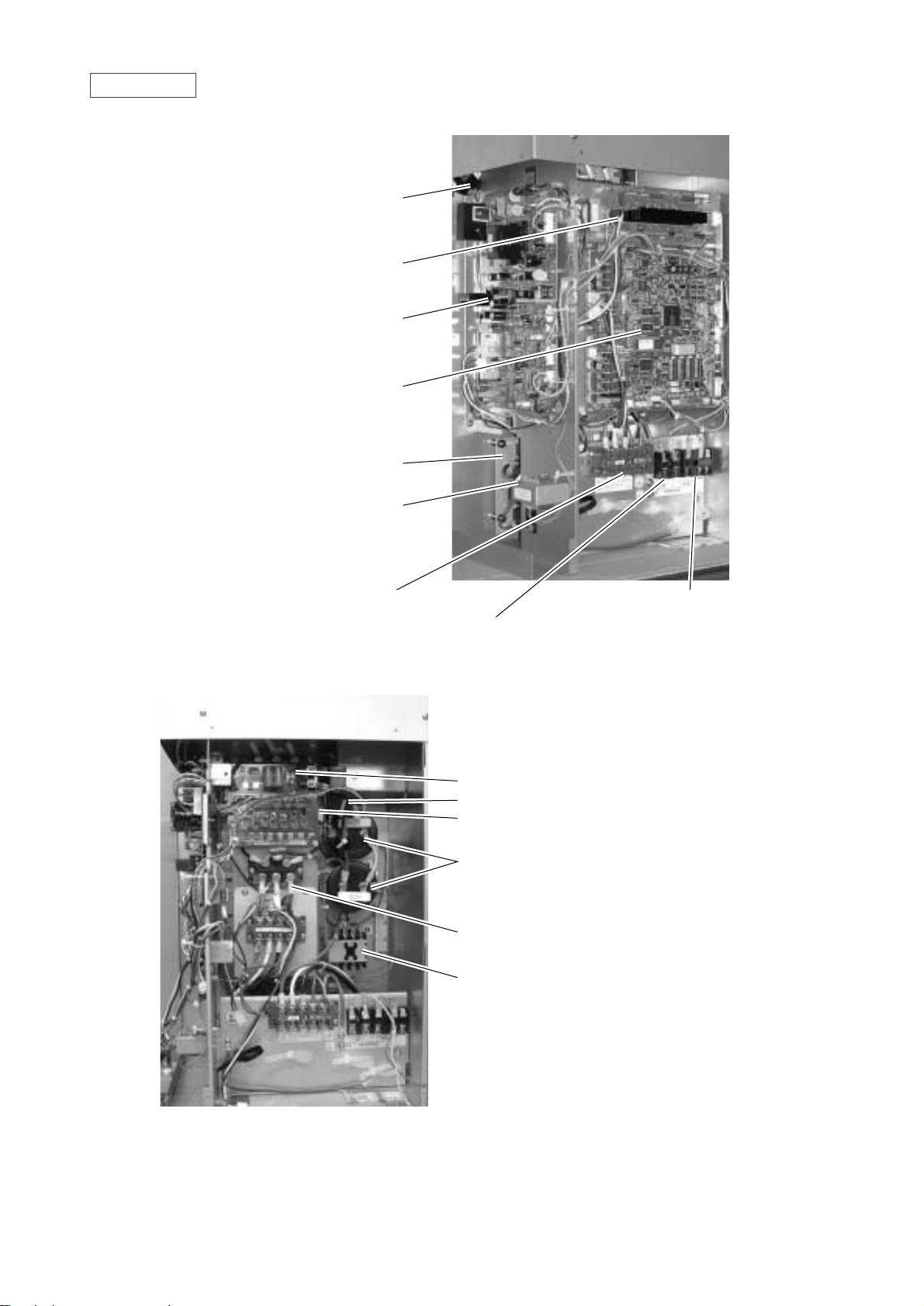
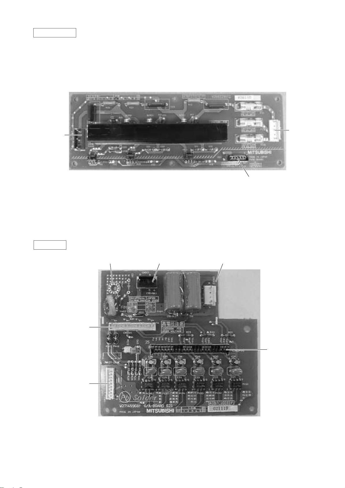
Controller Box
FANCON board
ACCT
INV board
MAIN board
Noise filter
Choke coil (L2)
Terminal block TB1A Power Source
Terminal block TB7 Transmission (Centralized control)
Terminal block TB3 Transmission
Inteligent Power Module (IPM)
G/A board
DCCT
Diode stack (DS)
Magnetic contactor (52C)
Capacitor (C2, C3)
(Smoothing capacitor)
- 9 -
Page 16

MAIN board
CN51
Indication distance
3-4 Compressor
ON/OFF
3-5 T roub le
CNRS3
Serial transmission to
INV board
CN3D
SW1
CNTR CNFC1
CNVCC4
Power source
for control(5V)
CN20
Power supply
3 L1
1 N
SW3
SW4
SW2 SWU2
SWU1
CNS1 CNS2 CN40 CN41 CNVCC3
Power Source
for control
1-2 30V
1-3 30V
4-6 12V
5-6 5V
CN3S
CN3N
LD1
Service LED
SWU3
CNTYP1
- 10 -
Page 17

INV board
CNDR2
Out put to
G/A board
CNTH
CNCT
DCCT
CN15V2
Power supply
CNFG
Frame grounding
for IPM control
CNCT2
ACCT
CNAC2 I
Power source
1 L2
3 N
5 G
CN52AC
Control for
52C
CNRS2CN FAN
Control for MF1
Serial transmission
to MAIN board
SW1
CNVDC
1-4
DC-560V
CNVCC4
Power supply (5V)
CNL2
Choke coil
CNVCC2
Power supply
1-2 30V, 1-3 30V
4-6 12V, 5-6 5V
- 11 -
Page 18
FANCON board
CNFAN
CNPOW
CNFC2
CN15V1
CNDR1
CNIPM1
G/A board
Terminal for
signal grounding
CNDC1 CNDC2
- 12 -
Page 19

- 13 -
RELAY 10 board
RELAY 4 board
Page 20

SLEV
ST2
TH5
SCC
TH8
ST7
ST4
LEV1
TH7
TH1
TH6
21S4
ST1
CJ1
O/S
63HS
Com
CJ2
CV1
ST3
SV1
CP1
ST5
S
M
63LS
63H
TH2
Dryer
CP2
ST10
SV4
ST9
HEX 1
ST11
HEX 2
SV2
ST6
BV3
CP3
SV3
ST8
BV1
BV2
[2] Refrigerant Circuit Diagram and Thermal Sensor
1PUHY-P200/250YREM-A
- 14 -
p
A
A
Page 21

[3]
1 PUHY-P200·250YREM-A
Electrical Wiring Diagram
<SYMBOL EXPLANATION>
Symbol
DCL
ACCT-U,W
52C
ZNR4 Varistor
DC reactor (Power factor improvement)
Current Sensor
Magnetic contactor (Inverter main circuit)
N a m e
Fan motor (Radiator panel)MF1
Solenoid valve (Discharge--suction bypass)SV1, SV2
4--way valve
21S4
✻1
Symbol
SLEV
SV3
Solenoid valve
(Heat exchanger capacity control)
SV4
Solenoid valve
(Heat exchanger capacity control)
LEV1
Electric expansion valve
(Sub-cool coil bypass)
N a m e
Choke coil (Transmission)L2
IPM Intelligent power module
TH5
TH2
TH1
N a m eSymbol
OA temp. detect
Pipe temp. detect
TH6
Saturation evapo. temp. detect
Discharge pipe temp. detect
Thermistor
Thermistor
bypass outlet temp. detect
at Sub--cool coil
TH8
Symbol N a m e
THHS Radiator panel temp. detect
Aux. relayX1~10
Earth terminal
DCCT
Current Sensor
Electric expansion valve
(Sub-cool coil bypass)
63HS High pressure sensor
63LS Low pressure sensor
liquid outlet temp. detect
at Sub--cool coil
TH7
R20
CNTYP1
(2P)
C4
BOX BODY
F01 250VAC 6.3AF
F03 250VAC 6.3AF
F02 250VAC 6.3AF
52C
ACCT
-U
BOX BODY
N
BOX BODY
BOX BODY
CNPOW
(5P)
SV3
SV4
circuit
detection
1
2
3
4
5
6
NF
TB1B
BOX BODY
X10
21S4
63H
X06
CN36
(6P)
CNFC1
(6P)
CNFC2
(6P)
CNFAN
(5P)
Control circuit board
(MAIN board)
Blue
Red
White
Black
Brown
Red
BOX BODY
Power circuit board
(INV board)
L2
MF1
THHS
CNVCC3
(6P)
CNVCC4
(2P)
X10
X01
X02
23
Black
Red
V
W
U
White
CNTR1
R3
R2
C3
C2
DCL
52C
C1
ZNR4
~
~
~
TB7
M2
M1
TB3
Blue
Black
Red
White
PE
L2
TB1A
CH1
SV1
L3
N
12V
CN51
(5P)
1
5
2
4
3
PE
1
L1
M1
S
Yellow
Orange
Purple
Black
White
Gray
1
2
3
4
V
W
N
U
MF
51234
P
N
L1 L2 L3
IPM
Orange
Brown
CN04
MC1
DCCT
DC-DC
Converter
CN3S
(3P)
CN3N
(3P)
SNOW
OFF
ON
1-2
CN3N
OFF
ON
1-3
ON
OFF
Mode
Auto
changeover
Normal
HEAT
COOL
✻
1
SV2
CN02
(8P)
321
TH6
63LS63HS
Red
White
Black
TH2
TH1
TH7TH5
LEV1
TH8
SLEV
no fuse breaker
Inverter
Controller Box
PUHY-P200YREM-A
PUHY-P250YREM-A
30A
30A
3216548721321321321543215421
CN03
(3P)
CN01
(2P)
CNH
(3P)
CNL
(3P)
CNLV1
(5P)
CNSLV
(5P)
Refer to the service handbook
about the switch operations.
Crank case heater
(Compressor)
High pressure
switch
1
2
3
CN38
(3P)
6
5
4
3
2
1
6
5
4
3
2
1
X03
X04
X05
X01
X02
CN32
(3P)
CN33
(3P)
CN34
(6P)
M2
Connect to
Indoor and
remote
controller
L2
L3
N
L1
Green/
Yellow
L2
L3
N
L1
L2
L3
N
L1
Blue
Black
Red
White
L2
L3
N
L1
Blue
Black
Red
DS
White
Power source
3N~
380/400/415V
50/60Hz
Terminal
Block
Noise
Filer
Terminal
Block
L1 L2 L3 N
Diode
stack
R1 R5
3214
3214
3
2
1
4
321476589
CNS2
(3P)
CNS1
(2P)
CN20
(3P)
32121
321321
CNTR
(3P)
F1
250VAC
2A T
F3
250VAC
1A F
T01
CNDC2
(4P)
UVW
Gate amp board
(G/A board)
ACCT
-W
Motor
(Compressor)
321654879 321654879
10 1211 13 14
3214321432 145
123123
Red
White
Black
1
2
3
4
5
6
5
4
3
2
1
4
3
2
1
Fan motor
(Heat exchanger)
Fan control board
(Fancon board)
CN3D
(3P)
1
2
3
1
2
3
1
2
3
Compressor
ON/OFF
NIGHT MODE
ORDEMEND
5: Trouble
4: Compressor ON/OFF
F02
700VDC
2A T
F01
250VAC
2A T
CNDR2
(9P)
CNVDC
(4P)
CNCT
(4P)
CNAC2I
(5P)
CNRS2
(7P)
CNVCC2
(6P)
CN15V2
(14P)
CNCT2
(4P)
1
2
3
1
5
6
2
4
3
1
5
6
2
4
3
1
2
3
1
2
1
2
1
5
6
7
2
4
3
1
5
6
7
2
4
3
CNRS3
(7P)
CNVCC4
(2P)
CNX10
(3P)
CN15V1
(14P)
CNDR1
(9P)
CNDC1
(4P)
321476589
121110 13 14
3
2
1
3
2
1
CN52CAC
(3P)
CNFAN
(3P)
CNTH
(2P)
CNL2
(2P)
2121
CNFG
(2P)
21
- 15 -
Page 22

• Cooling
Outdoor unit
Items
PUHY-P200YREM-A
PUHY-P250YREM-A
Indoor
Outdoor
Quantity
Quantity in operation
Model
Main pipe
Branch pipe
Total piping length
27.0/19.0 27.0/19.0
35.0/24.0 35.0/24.0
4
4
4
4
71 63 50 20 100 71 63 20
55
10 10 10 10 10 10 10 10
45 45
Hi Hi Hi Hi Hi Hi Hi Hi
11.7 11.7
270 420 360 250 360 270 420 250
122
200
1
272
50
2.00/0.55 2.08/0.54
81 80
42 44
16 16
17 17
20 20
55
44 44
20 22
13 13
20 20
14 14
0.23 0.23
10.6 9.7 14.4 13.2
380 415 380 415
Indoor unit fan notch
Refrigerant volume
Total current
Volts
Indoor unit
SC (LEV1)
Oil back (SLEV)
High pressure/Low pressure (after O/S)
(before Accumulator)
Pressure
DB/WB
Set
–
m
–
kg
A
V
Pulse
MPa
˚C
Condition
Sectional temperature
Outdoor unit
LEV opening
Inlet
Outlet
Outdoor
unit
Indoor
unit
OC
Ambient temp.
Indoor unit
Piping
Discharge (TH1)
Heat exchanger outlet (TH5)
Accumulator
Suction (Comp)
CS circuit (TH2)
Shell bottom (Comp)
SCC outlet (TH7)
Bypass outlet (TH8)
LEV inlet
Heat exchanger outlet
[4] Standard Operating Data
1 PUHY-P200·250YREM-A
- 16 -
Page 23

Outdoor unit
Items
PUHY-P200YREM-A PUHY-P250YREM-A
Indoor
Outdoor
Quantity
Quantity in operation
Model
Main pipe
Branch pipe
Total piping length
20.0/– 20.0/–
7.0/6.0 7.0/6.0
44
44
55
71 63 50 20 100 71 63 20
10 10 10 10 10 10 10 10
45 45
Hi Hi Hi Hi Hi Hi Hi Hi
11.7 11.7
290 470 410 250 330 290 470 250
0
123
0
200
2.10/0.43 2.10/0.38
73 80
0 –2
20
20
42
–4 –6
33 33
34 34
60 60
0.28 0.28
11.4 10.5 15.1 13.8
380 415 380 415
Indoor unit fan notch
Refrigerant volume
Total current
V
olts
Indoor unit
SC (LEV1)
Oil back (SLEV)
High pressure/Low pressure (after O/S)
(before Accumulator)
Pressure
DB/WB
Set
–
m
–
kg
A
V
Pulse
MPa
˚C
Condition
Sectional temperature
Outdoor unit
LEV opening
Discharge (TH1)
Heat exchanger inlet (TH5)
Accumulator
Suction (Comp)
CS circuit (TH2)
Shell bottom (Comp)
Heat exchanger outlet
Heat exchanger inlet
Inlet
Outlet
Outdoor
unit
Indoor
unit
OC
Ambient temp.
Indoor unit
Piping
• Heating
- 17 -
Page 24

1 PUHY-P200·250YREM-A
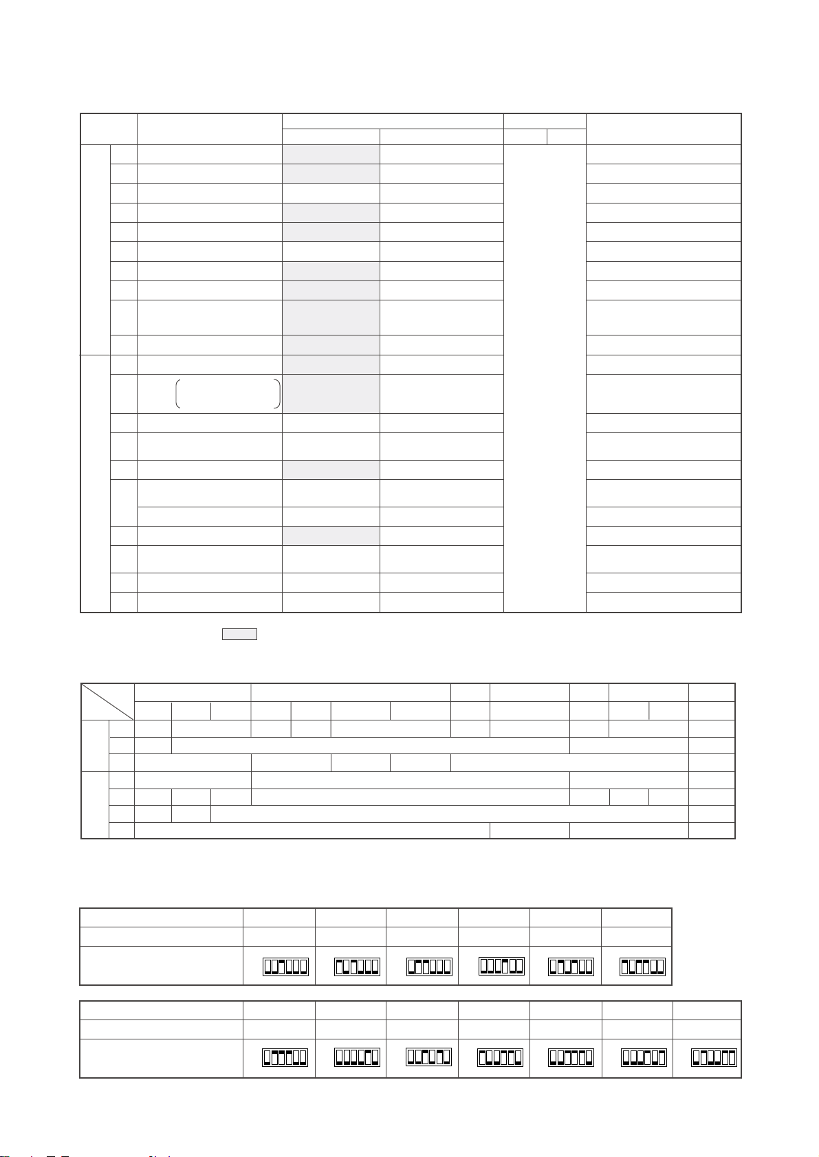
Switch Function
Function according to switch operation Switch set timing
When off When on When off When on
SWU
SW1
SW2
SW3
SW4
1~2
1~8
3
9~10
1
2
3
4
5
6
7
8
9
10
1
2
3
4
5
6
7
8
9
10
1
2
3
Unit address setting
Refrigerant model
For self diagnosis/
operation monitoring
–
Centralized control switch
Deletion of connection
information.
Deletion of error history.
Refrigerant amount adjustments
–
Disregard ambient air
sensor errors, liquid
overflow errors.
Forced defrosting
Defrost prohibited timer
–
–
SW3-2 Function valid/
invalid
Indoor unit test operation
Defrosting start temperature of TH
Defrosting end temperature of TH5.
Opening angle of IC except
when heater thermostat is
ON during defrosting.
–
Pump down
Target Tc (High pressure)
in Heating
–
Models
Models
SW4-2 Function valid/
invalid
Configuration compensation value
–
Set on 51~100 with the dial switch.
LED Monitering Displa
See Note2.
R407C R22
y
–
Centralized control not
connected.
Storing of refrigeration
system connection
information.
–
Ordinary control
–
Errors valid.
Ordinary control
39 min.
–
–
SW3-2 Function invalid
Stop all indoor units.
(no operation)
–
Ordinary control
49˚C
–
Invalid
–
–
Centralized control
connected.
Deletion of refrigeration
system connection
information.
Deletion
Adjustment operation
–
Disregard errors.
Start forced defrosting.
90 min.
–
–
SW3-2 Function valid
All indoor units test
operation ON.
–7˚C
For 2 minutes.For 2 minutes.
2000
–
Pump down
53˚C
–
Valid
–
Before power is turned on.
During normal operation when power
is on.
Should be set on OFF.
Before power is turned on.
Before power is turned on.
During normal operation when power
is on.
During normal operation when power is on
(only when switching from OFF/ON)
–
During normal operation when power
is on.
During normal operation when power
is on. (Except during defrosting)
–
–
During normal operation when power
is on.
When SW3-1 is ON after power is
turned on.
During normal operation when power
is on.
During normal operation when power
is on. (Except during defrosting)
–
During normal operation
(only when switching from OFF/ON)
During normal operation when power
is on.
–
–
Before power is turned on.
During normal operation when power
is on.
When SW4-1 is ON.
–
––– –
––– –
––
–
–
––
Night mode/Step demand
SWU3
R407C
Exist
R407C
Different unit model error
(7130)
Not exist
Different unit model error
(7130)
R22
R22
TH2
Night mode
Step demand
During normal operation when power is on.
–
–
–– –
–
– –
During normal
operation when
power is on.
10 minutes or
more after
compressor
starts.
Note 1
Note 2
• SWU1~2=00 when shipped from the factory. Other factory settings are indicated by shaded portions.
• If the address is set from 01 to 50, it automatically becomes 100.
•
The refrigerant model is recognized with SW3 and TH2.
Changes as shown below by on off change
0% 3%
6% 9% 12% –6% –3% 0%
4
5
6
7
8
9
10
[5] Function of Dip SW and Rotary SW
(1) Outdoor unit
Before power is turned on.
SW3-9
OFF
OFF
P200YREM-A–P250YREM-A
ON
–
ON
SW3-10
10˚C 15˚C
– 10˚C
- 18 -
Page 25
(2) Indoor unit
DIP SW1, 3
Model P71 P80 P100 P125 P140 P200 P250
Capacity (model name) code
14 16 20 25 28 40 50
SW2 setting
Model P20 P25 P32 P40 P50 P63
Capacity (model name) code
45 681013
SW2 setting
ON
OFF
ON
OFF
ON
OFF
ON
OFF
ON
OFF
ON
OFF
ON
OFF
ON
OFF
ON
OFF
ON
OFF
ON
OFF
Note 1: The shaded part indicates the setting at factory shipment. (For the SW not being shaded, refer to the
2: When both SW1-7 and SW1-8 are being set to ON, the fan stops at the heating thermostat of OFF.
table belo
Note 3: The DipSW setting is only effective during unit stopping (remote controller OFF) for SW1,2,3 and 4 commonly
and the power source is not required reset.
w.)
Setting of DIP SW2
Indoor unit inlet
None
100h
Ineffective
Fan output display
At stationary heating
Very low speed
SW1-7 setting
Ineffective
Ineffective
Heat pump
None
None
None
1st setting
Down blow B, C
Effective
–
Effective
–
–
Built in remote controller
Provided
2500h
Effective
Thermo. ON signal display
Always at heat.
Low speed
Set airflow
Effective
Effective
Cool.only
Provided
Provided
Provided
2nd setting
Horizontal
–
Ineffective
Ineffective
–
–
Room temp. sensor position
Clogged filter detect.
Filter duration
OA intake
Remote display select.
Humidifier control
Heating thermo. OFF airflow
Heating thermo. OFF airflow
Power failure automatic
return
Power source start/stop
Model selection
Louver
Vane
Vane swing function
Vane horizontal angle
V
Vane first angle
ane angle set for cooling
–
Heating 4deg up
–
–
Alw
PLFY-VLMD-B only
ays ineffective for PKFY-P.VAM
Not provided for PKFY-P.VAM
Provided for PLFY-P.VGM (ON) setting
Always down blow B,C for PKFY-P.VAM
Horizontal (ON) setting for PLFY-P. VLMD-A
Ineffective (ON) setting for floor
standing
SW1
SW3
1
2
3
4
5
6
7
8
9
10
1
2
3
4
5
6
7
8
9
10
Switch SW name
Operation by SW
Switch set timing
OFF ON OFF ON
Remarks
At unit stopping
(at remote
controller OFF)
Cooling capacity saving
for PKFY-P. VAM,
effective/ineffective
Model
Switch
SW1
SW3
3
6
7
3
4
6
8
PLFY-P
VAM-A(2)
OFF
OFF
VLMD-B
VKM-A
OFF
ON
ON
ON
OFFONON
ON
PEFY-P
VML-A VMH-A
20~80VMM-A
100~140VMM-A
OFF
OFF ON
OFF ON
ON
ON
OFF
OFF
OFF
OFF
ON OFF
ON OFF ON
ON
ON
ON
OFF
PDFY-P PFFY-P PCFY-P PKFY-P
VM-A
ON
VLRM-A, VLEM-A
OFF
VGM-A
PMFY-P
VBM-A
ON
V AM-A VGM-A
OFF OFF
OFF
OFF
OFF
OFF
OFF
- 19 -
OFF
ON
OFF
ON
Page 26

Ceiling height
3 3.5 m
2 2.8 m
1 2.3 m
Switch Function Operation by switch Switch set timing
SWA
SWA
SWA
SWB
SWC
Ceiling height setting
External static
pressure setting
For options
Setting of air outlet opening
Airflow control
(PLFY-P-VKM-A) (PCFY-P-VGM-A)
(PLFY-P125VLMD-B)
(PLFY-P-VKM-A)
(PLFY-P-VKM-A, PCFY-P-VGM-A, PKFY-P-VGM-A, PDFY-P-VM-A)
❇
The ceiling
height is
changed by
SWB setting.
❇
As this switch is used by interlocking with SWC,
refer to the item of SWC for detail.
SWA
SWB
123
2-way 3.5 m 3.8 m 3.8 m
3-way 3.0 m 3.3 m 3.5 m
4-way 2.7 m 3.0 m 3.5 m
❇
Set to the option to install the high efficiency
filter
Always after powering
Always after powering
Always after powering
Always after powering
Always after powering
3
1
2
2-way
4-way
3-way
3
1
2
3
1
2
3
1
2
Option
Standard
(PDFY-P20 ~ 80VM-A, PEFY-P20 ~ 80VMM-A)
100Pa
50Pa
30Pa
❇
For other models, change the setting of static pressure by replacing the connector.
Setting of DIP SW4 Setting of DIP SW5
12345
ON OFF ON OFF
ON OFF ON OFF
OFF
OFF
OFF OFF ON
ON OFF OFF
OFF
ON
ON
OFF ON OFF ON
OFF
OFF
OFF ON ON
ON
–
–
–
–
–
–
––
–
–––
–
–
–
–
–
–
ON ON
ON
ON
OFF
OFF
OFF
OFF
OFF
OFF OFF OFF
–
ON ON ON
–
OFF OFF OFF
–
ON OFF OFF
–
OFF OFF ON
–
ON ON ON OFF
PMFY-P-VBM-A
PLFY-P125VLMD-B
PDFY-P20 ~ 80VM-A
PLFY-P40 ~ 63VKM-A
PLFY-P80 ~ 125VAM-A(2)
PCFY-P-VGM-A
PKFY-P-VGM-A
PKFY-P-VAM-A
PEFY
PLFY-P20~100VLMD-B
-P20 ~ 80VMM-A
PFFY-P-VLEM-A, P-VLRM-A
PEFY-P20 ~ 32VML-A
PEFY-P40 ~ 140VMH-A
PEHY-P200·250VMH-A
PDFY-P100·125VM-A
PEFY-P100 ~ 140VMM-A
Model Circuit board used
SW4
Phase control
Relay selection
220V
240V
- 20 -
Page 27

£ TEST RUN
[1] Before Test Run
(1) Check points before test run
1 Neither refrigerant leak nor loose power source/ transmission lines should be found.
2 Confirm that the resistance between the power source terminal block and the ground exceeds 2MΩ by measur-
ing it with a DC500V megger. Do not run if it is lower than 2MΩ.
Note) Never apply the megger to the MAIN board. If applied, the MAIN board will be broken.
3 Confirm that the Ball valve at both gas and liquid sides is being fully opened.
Note) Certainly close the cap.
45Be sure that the cr
Prior to Ver.E
The number of indoor units and the total number of remote controllers id displayed within the parenthesis ( ).
16 (32)
16 (32)
200 or lower
200 or higher
After Ver.F
20 (40)
16 (32)
(
❇
1)
Capability of the
connected indoor units
Number of connected indoor units that
can be connected without a RP.
Remote controller type
Remote controller PAR-F25MA
ankcase heater has been powered by turning the main power source on at least 12 hours
before starting the test run. The shorter powering time causes compressor trouble.
(2) Caution at inverter check
Because the inverter power portion in outdoor unit electrical part box have a lot of high voltage portion, be sure to follow
the instructions shown below.
During energizing power source, never touch inverter power portion because high voltage (approx. 580V) is
applied to inverter power portion.
When checking,
Shut off main power source, and check it with tester, etc.
Allow 10 minutes after shutting off main power source.
Open the MAIN board mounting panel, and check whether voltage of both ends of electrolytic capacitor is
20V or less.
1
2
1
2
3
If any of the power supply wires (L1, L2, L3, N, ) are mistakenly connected, it is possible to damage the unit.
Please exercise caution.
6
A transmission booster (RP) is required when the number of connected indoor unit models in a cooling system
exceeds the number of models specified in the chart below.
Note: The maximum number of units that can be controlled is determined by the indoor unit model, the type of
remote controller and their capabilities.
(
❇
1) If even one unit that is higher than 200 exists in the cooling system, the maximum capacity will be “200 or
higher”.
❇
Please refer to the installation manual for more details.
❇
Before turning power on to the outdoor unit, first turn on the transmission booster. (If the outdoor unit are mistakenly
turned on first, turn on the transmission booster and then reset the outdoor unit power.)
- 21 -
Page 28

(3) Check points for test run when mounting options
(4) Attention for mounting drain water lifting-up mechanism
Check point
Local remote controller displays code
No. “2503”, and the mechanism stops.
No overflow from drain pan.
Drain water comes out by operations of
drain pump.
Sound of pump operations is heard, and
drain water comes out.
No water leakage from connecting
portions of water piping.
Water is supplied to water supply tank,
and float switch is operating.
Built-in optional parts
Mounting of drain
water removing
mechanism
Mounting of permeable film humidifier
Content of test run
Release connector of pump circuit,
check error detection by pouring
water into drain pan water inlet.
After that, connect connector of
circuit.
Check pump operations and drainage status in cooling (test run) mode.
Check humidifier operations and water
supply status in heating (test run) mode.
1
2
3
4
5
Result
1
2
3
Work
Disassembling and
assembling of drain
water removing
mechanism
Mounting of float
switch
Electric wiring
Float switch moves smoothly.
Float switch is mounted on
mounting board straigh and
without deformation.
Float switch has no contact with
copper pipe.
Wiring procedure is exactly followed.
Connector portion is tightly hooked.
Content of test run
Lead wire from the control box is not
damaged.
Rubber cap is properly inserted into
drain water outlet of the drain pan?
Insulation of gas and liquid
pipe is dealt with as shown in the
right figure?
Drain pan and piping cover are
mounted without gap?
Drain pan hooked on cut projection
of the mechanism?
Float switch is installed without contacting
the drain pan?
No mistakes in wiring?
Connectors connected securely and
tightly?
No tension on lead wire when sliding
on control box?
1
2
3
1
2
3
Check point Result
Insulation pipe
No gap
- 22 -
Page 29

- 23 -
(5) Check points for system structure
ex. PUHY-P200YREM-A
Check points from installation work to test run.
Trouble
Not operate.
Not cool (at cooling).
Not heat (at heating).
Not cool, not heat, error stop.
Condensation drip in piping.
Not cool, not heat, error stop.
Water leak, condensation drip in drain piping.
Error stop, not operate.
Electric shock.
Error stop, not operate.
Some electric parts should be damaged.
Classification
Installation and
piping
Power source
wiring
Portion
1
2
3
4
5
6
7
8
1
2
3
4
Check item
Instruction for selecting combination of outdoor unit,
and indoor unit followed? (Maximum number of indoor
units which can be connected, connecting model name,
and total capacity.)
Follow limitation of refrigerant piping length? For example, 80m or less (total length : 240m) at the farthest.
Connecting piping size of branch piping correct?
Refrigerant piping diameter correct?
Refrigerant leak generated at connection?
Insulation work for piping properly done?
Specified amount of refrigerant replenished?
Pitch and insulation work for drain piping properly done?
Specified switch capacity and wiring diameter of main
power source used?
Proper grounding work done on outdoor unit?
The phases of the L line (L1, L2, L3) correct?
L line and N line connected correct?
Page 30

Classification
Transmission
line
Portion Check item
¡
Limitation of transmission line length followed? For
example, 200m or less (total length : 500m) at the farthest.
™ 1.25mm2 or more transmission line used?
(Remote controller 10m or less 0.75mm
2
)
£ 2-core cable used for transmission line?
¢
Transmission line apar t from power source line by 5cm or more?
∞ One refrigerant system per transmission line?
§
The short circuit connector is changed form CN41 to
CN40 on the MAIN board when the system is centralized
control? (Just one outdoor unit. Not all outdoor units.)
¶ • No connection trouble in transmission line?
• Connection of wrong remote controller line terminals?
• MA Remote controller : TB15
• M-NET Remote controller : TB5
Trouble
Erroneous operation, error stop.
Erroneous operation, error stop.
Error stop in case multiple-core
cable is used.
Erroneous operation, error stop.
Not operate.
Not operate.
Error stop or not operate.
Never finish the initial mode.
System set
Before starting
Error stop or not operate.
Can not be properly set with power
source turned on.
Not operate.
Set temperature not obtained at
heating operations (Thermostat
stop is difficult)
Error stop.
Error stop, compressor trouble.
1
2
1
2
3
4
Address setting properly done? (M-NET Remote
controller, indoor unit and outdoor unit.)
Setting of address No. done when shutting off power
source?
Address numbers not duplicated?
Turned on SW3-8 on indoor unit circuit board when
mounting room thermistor sensor?
Refrigerant piping ball valve (Liquid pressure pipe, gas
pressure pipe) opened?
Turn on power source 12 hours before starting operations?
STAND BY
DEFROST
ERROR CODE
D A I L Y
AUTO OFF
CENTRALLY CONTROLLED
CLOCK
REMAINDER
ON OFF
˚C
1Hr.
NOT AVAILABLE
˚C
CHECK MODE
FILTER
CHECK
TEST RUN
LIMIT TEMP.
ON/OFF
TEMP
FILTER
CHECK TEST
ON OFF
CLOCK
PAR-F27MEA
TIMER SET
2 31
Breakers
for Current
Leakage
Switch
- 24 -
1Hr.
˚C
ON OFF
CLOCK
REMAINDER
ERROR CODE
˚C
ON OFF
CLOCK
NOT AVAILABLE
CHECK MODE
LIMIT TEMP.
ON/OFF
FILTER
TEST RUN
FILTER
CHECK TEST
PAR-F27MEA
STAND BY
DEFROST
CENTRALLY CONTROLLED
D A I L Y
AUTO OFF
CHECK
TEMP
TIMER SET
Page 31

[2] Test Run Method
Operation procedure
1
Turn on universal power supply at least 12 hours before getting started Displaying “HO” on display panel for
about two minutes.
2 Press
TEST RUN
button twice Displaying “TEST RUN’’ on display panel.
3 Press
selection button Make sure that air is blowing out.
4
Press
select button to change from cooling to heating operation, and vice versa Make sure that
warm or cold air is blowing out.
5 Press
adjust button Make sure that air blow is changed.
6 Press
or button to change wind Make sure that horizontal or downward blow is adjustable.
7 Make sure that indoor unit fans operate normally.
8 Make sure that interlocking devices such as ventilator operate normally if any.
9 Press
ON/OFF
button to cancel test run Stop operation.
Note 1: If check code is displayed on remote controller or remote controller does not operate normally.
2: Test run automatically stops operating after two hours by activation of timer set to two hours.
3: During test run, test run remaining time is displayed on time display section.
4: During test run, temperature of liquid pipe in indoor unit is displayed on remote controller room temperature
display section.
5: When pressing
adjust button, depending on the model, “NOT AVAILABLE” may be displayed on remote
controller. However, it is not a malfunction.
6: When pressing
or button, depending on the model, “NOT AVAILABLE” may be displayed on
remote controller. However, it is not a malfunction.
- 25 -
Page 32

¢
GROUPING REGISTRATION OF INDOOR UNITS WITH M-NET REMOTE CONTROLLER
(1) Switch function
• The switch operation to register with the remote controller is shown below:
Registration/
ordinary mode
selector switch
Registration/ordinar
mode selection switch
Switch to assign indoor
unit address
Registration switch
Confirmation switch
Delete switch
Registered mode
selector switch
Switch to assign
interlocked unit address
A + B
C
D
E
F
G
H
This switch selects the ordinary mode or registered mode (ordinary
mode represents that to operate indoor units).
❇
To select the registered mode, press the
FILTER
+
switch continuously for over 2 seconds under stopping state.
[Note] The registered mode can not be obtained for a while after
powering.
Pressing the
FILTER
+
switch displays “CENTRALLY
CONTROLLED”.
This switch assigns the unit address for “INDOOR UNIT ADDRESS
NO.”
This switch is used for group/interlocked registration.
This switch is used to retrieve/identify the content of g roup and
interkloced (connection information) registered.
This switch is used to retrieve/identify the content of group and
interlocked (connection information) registered.
This switch selects the case to register indoor units as group (group
setting mode) or that as interlocked (interlocked setting mode).
❇
The unit address is shown at one spot for the group setting mode
while at two spots for the interlocked setting mode.
This switch assigns the unit address of “OA UNIT ADDRESS NO.”
Symbol
of switch
G Registered mode
selector switch
E Confirmation switch
C Switch to assign
indoor unit address
H Switch to assign inter-
locked unit address
D Registration switch
A
+
FILTER
TEST RUN
Name Name of actual switch Description
of TEMP
of TIMER SET
CLOCK ON OFF
B
Registration/
ordinary mode
selector switch
STAND BY
DEFROST
ERROR CODE
D A I L Y
AUTO OFF
CENTRALLY CONTROLLED
CLOCK
REMAINDER
ON OFF
˚C
1Hr
NOT AVAILABLE
˚C
CHECK MODE
FILTER
CHECK
TEST RUN
LIMIT TEMP.
ON/OFF
TEMP
FILTER
CHECK TEST
ON OFF
CLOCK
PAR-F27MEA
TIMER SET
F Delete switch
- 26 -
Page 33

(2) Attribute display of unit
• At the group registration and the confirmation/deletion of registration/connection information, the type (attribute) of the
unit is displayed with two English characters.
Display Type (Attribute) of unit/controller
Indoor unit connectable to remote controller
Outdoor unit
Local remote controller
System controller (MJ)
[Description of registration/deletion/retrieval]
• The items of operation to be performed by the remote controller are given below. Please see the relating paragraph for
detail.
¡ Group registration of indoor unit
• The group of the indoor units and operating remote controller is registered.
• It is usually used for the group operation of indoor units with different refrigerant system.
™ Retrieval/identification of group registration information of indoor units
• The address of the registered indoor units in group is retrieved (identified).
£ Retrieval/identification of registration information
• The connection information of any unit (indoor/outdoor units, remote controller or the like) is retrieved (identified).
¢ Deletion of group registration information of indoor units
• The registration of the indoor units under group registration is released (deleted).
∞ Deletion of the address not existing
• This operation is to be conducted when “6607” error (No ACK error) is displayed on the remote controller caused by
the miss setting at test run, or due to the old memory remained at the alteration/modification of the group composition.
Caution:
When MELANS (MJ-103MTRA for example) is being connected, do not conduct the group/pair registration using
the remote controller. The group/pair registration should be conducted by MELANS. (For detail, refer to the instruc-.
tion exclusively prepared for MELANS.)
OA Processing
Lossnay
- 27 -
Page 34

(3) Group registration of indoor unit
1) Registration method
• Group registration of indoor unit ........................................................................ ¡
The indoor unit to be controlled by a remote controller is registered on the remote controller.
[Registration procedure]
1 With the remote controller under stopping or at the display of “HO”, continuously press the + switch
FILTER
( A + B ) at the same time for 2 seconds to change to the registration mode. (See the figure below.)
2 Assign the indoor unit address to “INDOOR UNIT ADDRESS NO.” by operating the (Room temperature
adjustment) (C).
Then press the switch (D) to register. In the figure below, the “INDOOR UNIT ADDRESS NO.” is being set
TEST RUN
to 001.
3 After completing the registration, press the + switch (A +B) at the same time for 2 seconds to
FILTER
change to the original ordinary mode (with the remote controller under stopping).
• Remote controller under stopping • “HO” under displaying
Ordinary mode
INDOOR UNIT
ADDRESS NO
ERROR CODE
OA UNIT ADDRESS NO
˚C
INDOOR UNIT
ADDRESS NO
ERROR CODE
OA UNIT ADDRESS NO
˚C
ERROR CODE
OA UNIT ADDRESS NO
˚C
1
1
Group setting mode
• Confirm the indoor unit address No.
• Confirm the connection of the transmission line.
ERROR CODE
OA UNIT ADDRESS NO
˚C
ERROR CODE
OA UNIT ADDRESS NO
˚C
• Registration complete
• Registration error
Indicates the type of unit
(Indoor unit in this case)
“88” flickers indicating registration error. (when the indoor unit.
registered is not existing)
2 Assign the
address (C)
1 Change to the
registration
mode (A + B)
3 Press the
registration
switch (D)
Remote controller
Indoor units
Group
2 + 3
ON/OFF
TEMP
FILTER
CHECK TEST
ON OFF
CLOCK
PAR-F27MEA
TIMER SET
System example
- 28 -
Page 35

2) Method of retrieval/confirmation
• Retrieval/confirmation of group registration information on indoor unit ............... ™
The address of the indoor unit being registered on the remote controller is displayed.
[Operation procedure]
1 With the remote controller under stopping or at the display of “HO”, continuously press the
FILTER
+ switch (A
+ B) at the same time for 2 seconds to change to the registration mode.
2 In order to confirm the indoor unit address already registered, press
switch (E). (See figure below.) When the group
of plural sets is registered, the addresses will be displayed in order at each pressing of
switch (E).
3 After completing the registration, continuously press the
FILTER
+ switch (A + B) at the same time for 2
seconds to change to the original ordinary mode (with the remote controller under stopping).
• Retrieval/confirmation of registration information ................................................ £
The registered information on a certain unit (indoor unit, outdoor unit, remote controller or the like) is displayed.
[Operation procedure]
1 With the remote controller under stopping or at the display of “HO”, continuously press the
FILTER
+ switch (A
+ B) at the same time for 2 seconds to change to the registration mode.
2 Operate
switch (G) for the interlocked setting mode. (See figure below.)
3 Assign the unit address of which registration information is desired to confirm with the
(TIMER SET) switch
(H). Then press the switch (E) to display it on the remote controller. (See figure below.)
Each pressing of
switch (E) changes the display of registered content. (See figure below.)
4 After completing the retrieval/confirmation, continuously press the
FILTER
+ switch (A + B) at the same time
for 2 seconds to change to the original ordinary mode (with the remote controller under stopping).
• Registered
• No registration.
ERROR CODE
OA UNIT ADDRESS NO
˚C
ERROR CODE
OA UNIT ADDRESS NO
˚C
1 Press the switch for confirmation (E)
Note: Only one address will be displayed
when the registration is one even the
switch is how often pressed.
Indicates the type of unit
(Indoor unit in this case)
1
1
ON/OFF
TEMP
FILTER
CHECK TEST
ON OFF
CLOCK
PAR-F27MEA
TIMER SET
- 29 -
Page 36

3) Method of deletion
• Deletion of group registration information of indoor unit ...................................... ¢
[Operation procedure]
1 With the remote controller under stopping or at the display of “HO”, continuously press the
FILTER
+
switch (A + B) at the same time for 2 seconds to change to the registration mode..
2 Press the
switch (E) to display the indoor unit address registered. (As same as ™)
3 In order to delete the registered indoor unit being displayed on the remote controller, press the
CLOCK ON OFF
(F) switch
two times continuously. At completion of the deletion, the attribute display section will be shown as “– – ”.
(See figure below.)
Note: Completing the deletion of all indoor units registered on the remote controller returns to “HO” display.
4 After completing the registration, continuously press the
FILTER
+ switch (A + B) at the same time for 2
seconds to change to the original ordinary mode (with the remote controller under stopping).
ERROR CODE
OA UNIT ADDRESS NO
˚C
INDOOR UNIT
ADDRESS NO
ERROR CODE
OA UNIT ADDRESS NO
˚C
INDOOR UNIT
ADDRESS NO
ERROR CODE
OA UNIT ADDRESS NO
˚C
1 Set the address
2 Press the switch for
confirmation (E)
• Registered
• No registration
❇
Same display will appear when
the unit of “007” is not existing.
1 Press the switch for confirmation ( F)
twice continuously.
• Deletion completed
• Deletion completed
In case group registration with other
indoor unit is existing
In case no group
registration with other
indoor unit is existing
1
1
1 + 2
“– –” indicates the
deletion completed.
˚C
˚C
(Alternative
display)
˚C
˚C
(Alternative
display)
INDOOR UNIT
ADDRESS NO
ERROR CODE
OA UNIT ADDRESS NO
˚C
2
ON/OFF
TEMP
FILTER
CHECK TEST
ON OFF
CLOCK
PAR-F27MEA
TIMER SET
ON/OFF
TEMP
FILTER
CHECK TEST
ON OFF
CLOCK
PAR-F27MEA
TIMER SET
- 30 -
Page 37

4) Deletion of information on address not existing
• Deletion of information on address not existing ................................................... ∞
This operation is to be conducted when “6607” error (No ACK error) is displayed on the remote controller caused by
the miss setting at test run, or due to the old memory remained at the alteration/modification of group composition,
and the address not existing will be deleted.
Note: The connection information (connection between indoor unit and outdoor unit) on the refrigerant system can
not be deleted.
An example to delete the system controller of “250” from the indoor unit of “007” is shown below.
[Operation procedure]
1 With the remote controller under stopping or at the display of “HO”, continuously press the
FILTER
+ switch (A
+ B) at the same time for 2 seconds to change to the registration mode.
2 Oper
ate
switch (G) for the interlocked setting mode ( ii ). (See the figure below.)
3 Assign the unit address existing to “OA UNIT ADDRESS No.” with the
(TIMER SET) switch (H), and press
switch (E) to call the address to be deleted. (See the figure below.) As the error display on the remote controller is usually
transmitted from the indoor unit, “OA UNIT ADDRESS No.” is used as the address of the indoor unit.
4 Press the
CLOCK ON OFF
switch (F) twice. (See the figure below.)
5 After completing the deletion, continuously press the
FILTER
+ switch (A + B) at the same time for 2 seconds
to return to the original ordinary mode (with the remote controller under stopping).
INDOOR UNIT
ADDRESS NO
ERROR CODE
OA UNIT ADDRESS NO
˚C
INDOOR UNIT
ADDRESS NO
ERROR CODE
OA UNIT ADDRESS NO
˚C
(Alternative
display)
INDOOR UNIT
ADDRESS NO
ERROR CODE
OA UNIT ADDRESS NO
˚C
INDOOR UNIT
ADDRESS NO
ERROR CODE
OA UNIT ADDRESS NO
˚C
(Alternative
display)
❇
❇
INDOOR UNIT
ADDRESS NO
ERROR CODE
OA UNIT ADDRESS NO
˚C
INDOOR UNIT
ADDRESS NO
ERROR CODE
OA UNIT ADDRESS NO
˚C
(Alternative
display)
❇
When both indoor
unit and interlocked
unit addresses are
existing
Deletion of
address not
existing
1 Set the address (H)
3 Press the deletion switch (F) twice
• Deletion completed
• Deletion completed
1 + 2
3
3
2 Press the switch for
confirmation (E)
ON/OFF
TEMP
FILTER
CHECK TEST
ON OFF
CLOCK
PAR-F27MEA
TIMER SET
- 31 -
Page 38

∞ CONTROL
[1] Control of Outdoor Unit
(1) Initial processing
• When turning on power source, initial processing of microcomputer is given top priority.
• During initial processing, control processing corresponding to operation signal is suspended. The control processing is resumed after initial processing is completed. (Initial processing : Data processing in microcomputer and
initial setting of each LEV opening, requiring approx. 2 minutes at the maximum.)
(2) Control at staring
• For 3 minutes after starting, 60Hz is the upper frequency limit.
(3) Bypass, capacity control
• Solenoid valve consists of bypass solenoid valve (SV1, SV2) bypassing between high pressure side and low
pressure sider. The following operation will be provided.
1) Bypass solenoid valves SV1 and SV2 (both “open” when turned on)
Item
When starting compressor
After thermost “ON is returned
and after 3 minutes restart
When compressor stops in
cooling or heating mode
After operation stops
During defrosting operations
During oil recovery opera-
tions
During 20Hz operations, at
fall in low pressure or low
pressure saturation temperature. (3 minutes or more after
starting)
When high pressure rises
(Pd)
When high pressure rises
(Pd) during 20Hz operations
(3 minutes after starting)
When discharge temperature
rises
(3 minutes after starting)
SV1
ON (Open) OFF (Close)
–
–
When Pd reaches
2.70MPa or more
When Pd is 2.35MPa
or less 30 seconds
SV2
ON (Open) OFF (Close)
–
–
Turned on when high
pressure (Pd) exceeds
pressure limit
When discharge temp. is
100°C or less
Compressor
Bypass
solenoid
valve (SV1)
(4-minute)
(2-minute) (8-minute) (3-minute)
Start
Thermo.
OFF
Thermo.
ON
Defrosting time
(
❇
1)
Stop
Turned on for 2 minutes Turned on for 2 minutes
Turned on for 4 minutes
Always turned on or until HPS and
LPS is within 0.2MPa.
Turned on for 3 minutes or until
HPS and LPS is within 0.2 MPa
Always turned on
Cooling operation normally OFF and heating operation normally ON
when performing oil recovery after continuous operation at low frequency.
Turned on for 4 minutes
Always turned on
When Ps is 0.15MPa or
less
When Ps is 0.25MPa or
more
When Pd reaches
2.50MPa or more
When Pd is 2.25MPa or
less after 30 seconds
When high pressure
(Pd) is 1.96MPa or less
When temp. exceeds
115°C and Pb reaches
1.47MPa or more
- 32 -
Page 39

(4) Frequency control
• Depending on capacity required, capacity control change and frequency change are performed to keep constant
evaporation temperature in cooling operations, and high pressure saturation temperature in heating operation.
• Frequency change is performed at the rate of 3Hz/second as follows.
1) Frequency control starting
• 60Hz is the upper limit for 3 minutes after starting.
2) Pressure control
3) Discharge temperature control
Discharge temperature (Td) of compressor is detected during operation. If the upper limit is exceeded, the frequency
is reduced. (Change rate : 5Hz of the present value)
• 30 seconds after starting compressor, control is performed every minute.
• Operation temperature is 110˚C : Td.
4) Periodical frequency control
Frequency controll is periodically performed except for the frequency controls at operation start, status change, and
protection.
1 Cycle of periodical frequency control
Periodical frequency control is performed every minute after the time specified below has passed.
• 60 sec after star
• 30 sec after frequency control by discharge temperature or pressure limit
2 Amount of frequency change
The amount of frequency change is controlled corresponding to evaporation temperature and high pressure
saturation temperature.
3-1 Back up of frequency control by bypass valve
During low frequency operation, frequency is backed up by turning on (opening) bypass valve (SV1).
• Cooling
3 minutes after starting compressor, bypass valve is turned on when Discharge Pressure(Pd) is higher than
2.5 MPa, and turned off when Pd is less than 2.25MPa.
• Heating
During low frequency operation,3 minutes after starting compressor, SV1 turned on when high pressure (Pd)
exceeds pressure limit of 2.5MPa and turned off when Pd falls to 2.25MPa
or less .
ON
OFF
2.25MPa 2.5MPa
The upper limit value for the high pressure (Pd) has been set for each
frequency, when this value is exceeded, the frequency is reduced every
30 seconds.
ting compressor or 30 seconds after finishing defrostoing operations
Cooling Heating
Unit Minimum
❇
❇
20Hz
...
TH6
>
=
20°C or TdSH
>
=
10deg.
❇
28Hz
...
TH6
<
=
20°C and TdSH
<
=
10deg.
Maximum
Unit Minimum Maximum
P200YREM-A 20Hz (28Hz) P200YREM-A 20Hz
61Hz
74Hz
66Hz
P250YREM-A 20Hz (28Hz) 79Hz
P250YREM-A 20Hz
100Hz
86Hz
3°C5°C
3°C5°C
Pressure limit
Compressor Frequency (Hz)
Pd
2.65MPa
2.45MPa
Max
30
- 33 -
Page 40

(6) Subcool coil control (electronic expansion valve <LEV1>)
• The amount of super heat detected from the bypass outlet temperature of subcool coil (TH8) is controlled to be
within a certain range for each 30 seconds.
• The opening angle is corrected and controlled depending on the outlet/inlet temperature of subcool coil (TH5, TH7)
and the discharge temperature.
• However, the valve will be closed (0) at heating and compressor stopping.
• It will fully open during defrosting.
(7) Defrost operation control
1) Starting of defrost operations
•
After integrated 39 minutes : The compressor operations, defrosting operations start when – 10˚C(R407C),
– 6˚C (R22) piping temperature (TH5) is detected for 3 consecutive minutes.
• Forcible defrosting operations start by turning on forcible defrost switch (SW2-7) if 10 minutes have already elapsed
after compressor star
• Defrost prohibit timer
Defrost will last a maximum of 15 minutes. Then next defrost time will be 39 minutes.
Minimum consecutive running minutes to defrost can be increaced from 39 minutes to 90 minutes by setting SW2-8 “ON”.
t or completion of defrosting operations and will last for 10 minutes.
2) Completion of defrosting operations
Defrosting operations stop when 10 minutes : It has passed since start of defrosting operation,
or piping temperature (TH5) reaches 10˚C or more.
(Defrosting operations do not stop for 2 minutes after starting, except when piping temperature exceeds 25˚C.)
3) Defrosting prohibition
Defrosting operations do not start during oil recovery, and for 10 minutes after starting compressor.
4) Trouble during defrosting operations
When trouble is detected during defrosting operations, the defrosting operations stop, and defrosting prohibition
time decided by integrated operation time of compressor is set to be 20 minutes.
5) Change in number of operating indoor units during defrosting operations
• In case number of operating indoor units changes during defrosting operations, the defrosting operations continue,
and control of unit number change is performed after the defrosting operations are finished.
• Even in case all indoor units stop or thermostat is turned off during defrosting operations, the defrosting operations
do not stop until expected defrosting activities are completed.
(5) Oil return control (Electronic expansion valve <SLEV>)
• Oil return LEV (SLEV) opening is dependent on compressor frequency and ambient temperature.
• SLEV is closed (0) when compressor stops, and SLEV is set (64) for 10 minutes after starting compressor.
Note 12TH5 - Y-Series
TdSH=Discharge Super Heat.
TdSH
40<TdSH
35<TdSH<40
20<TdSH<35
10<TdSH<20
TdSH<10
-
-
-
-
15°C<TH5/TH7
AL=0
AL=0
AL=0
AL=1
AL=2
-
-
-
-
-
-
20~45Hz
AL=0
AL=1
AL=1
AL=1
AL=2
Compressor
Frequency
46~70Hz
AL=0
AL=0
AL=1
AL=1
AL=2
71Hz~Fmax
AL=0
AL=0
AL=0
AL=1
AL=2
TdSH
80<TdSH
60<TdSH<80
40<TdSH<60
10<TdSH<40
TdSH<10
-
-
-
-
-
-
-
-
-
-
-
-
-
-
-
-
TH5/TH7 5°C
AL=0
AL=1
AL=1
AL=1
AL=2
TH5/TH7
-
-
5°C<TH5/TH7
15°C
AL=0
AL=0
AL=1
AL=1
AL=2
(8) Judgment of Refrigerant amount
Accumulator design
Cooling
Heating
=Td-Tsg ( low pressure saturation temperature)
-
-
-
-
-
-
-
-
- 34 -
Page 41

(9) Refrigerant Recovery Control
1) Start of Refrigerant recover in Heating Start of Refrigerant recover is Cooling
2) Refrigerant recovery operation in heating
3) Refrigerant recovery operating in cooling
• Refrigerant is recovered by opening LEV of the objective indoor units (indoor units under stop. fan, and cooling
Refrigerant is recovered by the opening of the indoor LEV further than the operation position for 30 seconds.
Refrigerant Recovery Control
modes, and that with heating thermostat being turned off) for 15 seconds.
• The regular capacity control of the outdoor unit and the regular LEV control of the indoor unit are not applied
during refrigerant recovery operation, but are fixed with the value before the recovery operation. These controls will
be conducted one minute after finishing the recovery operation.
• Defrosting operation is prohibited during the recovery operation, and it will be conducted after finishing the recov-
ery operation.
Starts
LEV opening
before change
LEV opening at refrigerant recovery
(Indoor unit LEV opening 500 pulse)
Finish
15 seconds
Refrigerant recovery is performed to prevent refrigerant from accumulating in the stopping unit, the unit under
cooling mode and that with heating thermostat being turned off.
Refrigerant recovery is started when all of the items
below are satisfied.
• 30 minutes has passed after finishing previous
refrigerant recovery and compressor frequency is
greater then 60Hz or Td less than 105°C or 15
minutes has passed since previous recovery was
performed and frequency is less than 60Hz and Td is
greater than 105°C.
• 15 minutes has passed from starting the
compressor.
• A1 = 0 for 3 minutes.
Refrigerant recovery is started when all of the items
below are satisfied.
• 30 minutes has passed after finishing previous
refrigerant recovery.
• Al = 0 for 3 minutes.
• Td is greater than 105°C or Pd is greater than 2.45
HPa and SCO is greater than 10°C.
(10) Control of outdoor unit fan and outdoor unit heat exchanger capacity control
1) Control system
Depending on capacity required, control outdoor fan flow rate with phase control, for maintaining evaporation
temperature (0˚C) in cooling operations, and high pressure saturated temperature (49˚C) in heating operations.
2) Control
• Outdoor unit fan stops when compressor stops.
• Fan is in full operation for 5 seconds after starting.
• Outdoor unit f
• Lower the fan strength upper limit to approximately 50% when performing night mode settings.
an stops during defrosting operations.
- 35 -
Page 42

Four-way valve
Compressor
Accumulator
CS circuit
TH2
LPS
Heat e
(HPS)
xchanger
Outdoor heat exchanger
Indoor heat
exchanger
Flow control
valve
(11) Circulating composition sensor (CS circuit)
•
• The condensing temperature (Tc) and the evaporating temperature (Te) are calculated from OC, high
pressure (HPS), and low pressure (LPS).
• The compressor frequency , the outdoor fan, and others are controlled according to the codensing temperature (Tc)
and the evaporating temperature (Te).
• CS circuit configuration (Outline drawing)
As shown in the drawing below; the CS circuit has the structure to bypass part of the gas discharged from the
compressor through the capillary tube to the suction side of the compressor, exchange heat before and after the
capillary tube,and produce two phase (gaseous and liquid) refrigerant at the capillary tube outlet. The dryness
fraction of refrigerant at the capillary tube outlet is estimated from the temperature of low pressure two phase
(gaseous and liquid) refrigerant at the capillary outlet (TH2) and the pressure (LPS) to calculate the composition of
refrigerant circulating the refrigeration cycle (
OC). In this series the high-pressure liquid refrigerant temperature is
calculated based on the high pressure and ambient air temperature values. It is found by utilizing the characteristic
that the temperature of two phase (gaseous and liquid) R407C under a specified pressure changes according to
the composition and dryness fraction (gas-liquid ratio in weight).
(12) Control at initial starting
• The following initial start mode will be performed when the unit is started for the first time after the power has
been turned on.
<Flow chart of initial start mode>
Start of initial operation mode
Initial operation mode is finished.
Step 1
••The compressor operated at F≤38Hz.
–
Finished operating time reaches 5 minutes.
Step 2
••The compressor is operated at less than or equal
to F
<
=
60 Hz.
Operates continuously for 20 minutes and finishes.
- 36 -
Page 43

[2] Operation Flow Chart
(1) Outdoor unit
Note: 1 For about 2 minutes after turning on power source, address and group information of outdoor unit, indoor unit, and remote
controller are retrieved by remote controller, during which “HO” blinks on and off on remote controller. In case indoor unit is
not grouped to remote controller, “HO” display on remote controller continues blinking even after 2 minutes after turning on
power source.
Note: 2 Two trouble modes included indoor unit side trouble, and outdoor unit side trouble. In the case of indoor unit side trouble,
error stop is observed in outdoor unit only when all the indoor units are in trouble. However, if one or more indoor units are
operating normally, outdoor unit shows only LED display without undergoing stop.
Note : 3 Operation mode conforms to mode command by indoor unit. However, when outdoor unit is in cooling operation, the
operation of indoor unit will be prohibited even by setting a part of indoor units under operation, or indoor unit under
stopping or fan mode to heating mode. Reversely when outdoor unit in heating operation, the same condition will be
commenced.
YES
NO
YES
NO
YES
YES
NO
NO
2
Normal operations
Trouble observed
Stop
“HO” blinks on the remote controller
Oil return LEV, SC coil LEV
fully closed
Variable capacity unit
1. 52C OFF
2. Inverter output 0 Hz
3. Outdoor fan Stop
4. All solenoid valve OFF
5. LEV1, SLEV full closed.
Breaker
turned on
Error code blinks on the
outdoor controller board
Start
Set indoor
address No. to
remote controller
Operation
command
Operation
mode
Error mode
52C ON
Operation
mode
Heating opera-
tions
Cooling opera-
tions
Operation mode command to indoor unit controller
Error stop
Error command to indoor
unit
Note: 1
Note: 2
Cooling, Heating
Fan
Note: 3
Error code blinks on the
remote controller
- 37 -
Page 44

(2) Indoor unit
Note: 1 At indoor unit LEV full closed, the opening angle indicates 41.
Note: 2 The error code includes that of indoor unit and that of outdoor unit. In the former case, the indoor unit in question only
stops in error mode, while in the later case, all indoor units connected to the outdoor unit stop in error mode.
Note: 3 The operation mode follows the mode command from the indoor unit. However, when the outdoor unit in cooling operation,
the operation of the indoor unit will be prohibited even a part of indoor units or indoor unit under stopping or fan mode is
put into heating mode. Reversily, when the outdoor unit is under heating operation, the same condition will be
commenced.
YES
NO
YES
NO
YES
NO
YES
NO
YES
NO
YES
NO
YES
NO
Normal operations
Trouble observed
Stop
Start
Breaker
turned on
Operation SW
turned on
1. Protection function
self-holding cancelled.
2. Indoor unit LEV full
closed.
Remove controller
display extinguished
3-minute drain
pupm ON
FAN stop
Drain pump
ON
Error mode
Error stop
Error code blinks on
the remote controller
Indoor unit LEV
full closed
Error code
blinks on the
outdoor
controller board
Operation mode
Heating
mode
Cooling
display
Cooling mode
Dry mode
Heating
display
Fan mode
Fan display
Dry display
Prohibition Prohibition
Heating
operations
Cooling
operations
Prohibition
Dry
operation
Fan
operations
Prohibition “Remote
controller blinking”
Note: 3 Note: 3
Note: 1
Note: 2
Note: 1
Error command
to outdoor unit
- 38 -
Page 45

(3) Cooling operation
YES
NO
YES
YES
NO
NO
1.Inverter output 0Hz
2.Indoor unit LEV, Subcool coil
bypass LEV fully closed
3.Solenoid valve OFF
4.Outdoor unit fan stop
1.Inverter frequency control
2.Indoor unit LEV, control
3.Solenoid valve control
4.Outdoor unit fan control
Cooling operation
4-way valve OFF
Indoor unit fan
operations
Test run start
Thermostat ON
Normal operations
Test run
Stop
3-minute
restart
prevention
- 39 -
Page 46

YES
YES
NO
YES
YES
NO
NO
NO
(4) Heating operation
Normal operations
Defrosting operations
Stop
Test run
1.Indoor unit fan very low speed
operations
2.Inverter output 0Hz
3.Indoor unit LEV
4.Solenoid valve OFF
5.Outdoor unit fan stop
6.
52C off
1.Indoor and outdoor unit fan
control
2.Inverter frequency control
3.Indoor unit LEV
4.Solenoid valve control
5.
52C control
1.Indoor unit fan stop
2.Inverter defrost frequency control
3.Indoor unit LEV fully opened
4.Solenoid valve control
5.Outdoor unit fan stop
6.52C control
Heating operation
4-way valve ON
Defrosting
operation
Test run start
4-way valve OFF
Thermostat ON
3-minute
restart
prevention
Note : 1 When outdoor unit starts defrosting, it transmits defrost operations command to indoor unit, and the indoor unit starts
defrosting operations.
Similarly when defrosting operation stops, indoor unit returns to heating operation after receiving defrost end command of
outdoor unit.
Note : 1
- 40 -
Page 47

YES
NO
YES
YES
NO
(5) Dry operation
Normal operations
Thermostat ON
Stop
1.Indoor unit fan stop
2.Inverter output 0Hz
3.Indoor unit LEV
4.Solenoid valve OFF
5.Outdoor unit fan stop
6.52C off
1.Outdoor unit (Compressor) intermittent operations
2.Indoor unit fan intermittent operations
(Synchronized with compressor :
low speed, OFF operations)
Dry operations
4-way valve OFF
Inlet temp. 18˚C
Note : 2
Thermostat ON
Test run start
Note : 1
Note : 1 When indoor unit inlet temperature exceeds 18˚C, outdoor unit (compressor) and indoor unit fan start intermittent operations
synchronously. Operations of outdoor unit, indoor unit LEV and solenoid valve accompanying compressor are the same as
those in cooling operations.
Note : 2 Thermostat is always kept on in test run, and indoor and outdoor unit intermittent operation (ON) time is a little longer than
normal operations.
- 41 -
Page 48

Low pressure shell scroll type
with capacity control mechanism
Winding resistance:
Each phase 0.583Ω (20˚C)
Setting
2.94MPa OFF
R120=7.465kΩ
B25/120=4057
Rt =
7.465exp{4057
( - )}
R
0=33kΩ
B
0/100=3965
Rt =
33exp{3965( - )}
-20˚C : 92kΩ
-10˚C : 55kΩ
0˚C : 33kΩ
10˚C : 20kΩ
20˚C : 13kΩ
30˚C : 8.2kΩ
R0=15kΩ
B0/100=3460
Rt =
15exp{3460( - )}
0˚C : 15kΩ
10˚C : 9.7kΩ
20˚C : 6.4kΩ
25˚C : 5.3kΩ
30˚C : 4.3kΩ
40˚C : 3.1kΩ
[3] List of Major Component Functions
MC
63HS
63LS
63H
TH1
(discharge)
TH2
(low pressure
saturation
temperature)
TH5
(piping
temperature)
TH6 (outdoor
air temperature)
TH7
TH8
(subcool coil
bypass outlet
temperature)
Compressor
High
pressure
sensor
Low
pressure
sensor
Pressure
switch
Thermistor
Adjust refrigerant circulation by
controlling operating frequency and
capacity control valve with operating
pressure.
1) High press. detection.
2) Frequency control and high
pressure protection
1) Detects low pressure
2) Calculates the refrigerant circulation configuration.
3) Protects the low pressure
1) High pressure detection
2) High pressure protection
1) Discharge temperature detection
2) High pressure protection
20˚C : 250kΩ 70˚C : 34kΩ
30˚C : 160kΩ 80˚C : 24kΩ
40˚C : 104kΩ 90˚C : 17.5kΩ
50˚C: 70kΩ 100˚C : 13.0kΩ
60˚C: 48kΩ 110˚C : 9.8kΩ
1) Detects the saturated vapor
temperature.
2) Calculates the refrigerant circulation configuration.
3) Controls the compressor frequency.
4) Controls the outdoor unit’s fan air
volume.
1) Frequency control
2) Defrost control and liquid level
detection at heating
1) Outdoor air temperature detection
2) Fan control, liquid level heater,
and opening setting for oil return
Subcool coil bypass LEV (LEV1)
Heat exchenger inlet pipe
temperature
control (subcool coil outlet temperature)
Subcool coil bypass LEV (LEV1)
control
Name Application Specification Check method
Pressure
0~0.98MP
0.3V/0.098MPa
a
Vout 0.5~3.5 V
Gnd (black)
Vout (white)
Vcc (DC5V) (red)
Pressure
0~2.94MP
0.1V/0.098MPa
a
Vout 0.5~3.5 V
Gnd (black)
Vout (white)
Vcc (DC5V) (red)
Connector
Connector
1
273+t
1
273+t
1
273+t
Continuity check
Resistance value
check
Resistance value
check
Outdoor unit
Symbol
(function)
63HS
63LS
1
273+120
1
273+0
1
273+0
- 42 -
Page 49

Name Application Specification Check method
Outdoor unit
Symbol
(function)
Thermistor
Solenoid
valve
Linear
expansion
valve
Linear
expansion
valve
Thermistor
THHS
SV1
SV2
(discharge suction bypass)
(discharge suction
bypass)
SV3 ~ 4
SLEV
LEV1
(SC coil)
LEV
TH21
(inlet air
temperature)
TH22
(piping
temperature)
TH23
(gas side
piping
temperature)
1) Detects the inverter cooling fin
temperature.
2) Provides inverter overheating
protection.
3) Controls the control box cooling
fan.
1) High/low press. bypass at starting/
stopping and capacity control at
low load
2)
Capacity control and high press. rise
suppression (backup for frequency
control)
Discharge press. rise suppression
Adjustment of liquid refrigerant (oil)
return foam accumulator
Adjustment bypass flow rate from
outdoor unit liquid line at cooling.
1) Adjust superheat of outdoor unit
heat exchanger outlet at cooling.
2) Adjust subcool of indoor unit heat
exchanger at heating.
Indoor unit control (thermostat)
21S4a 4-way valve Changes for cooling and heating
CH1 Crank case
heater
Heating of compressor refrigerant
1) Indoor unit control (freeze
prevention, hot adjust, etc.)
2) LEV control in heating operation
(Subcool detection)
LEV control in cooling operation
(Superheat detector)
R
50=17kΩ
B25/50=4170
Rt =
17exp{4170( - )}
-20˚C : 605.0kΩ50˚C : 17.0k
Ω
-10˚C : 323.3kΩ60˚C : 11.5k
Ω
0˚C : 180.9kΩ70˚C : 8.0k
Ω
10˚C : 105.4kΩ80˚C : 5.7k
Ω
20˚C : 63.8kΩ90˚C : 4.1k
Ω
30˚C : 39.9kΩ100˚C : 3.0k
Ω
40˚C : 25.7k
Ω
AC 220~240V
Open at energizing and
close at deenergizing
DC12V stepping motor drive
Valve opening 0~480 pulse
DC12V
Cord heater AC 220~240V
MC......1280Ω
.......45W
Opening of stepping motor
driving valve
0~2,000 pulses
R
AC220~240V
on cooling
off heating
0 = 15kΩ
B0/100 = 3460
Rt =
15exp {3460 ( - )}
0°C :15kΩ
10°C : 9.7kΩ
20°C : 6.4kΩ
25°C : 5.3kΩ
30°C : 4.3kΩ
40°C : 3.1kΩ
• Continuity check by tester
• Temperature of inlet and outlet
Continuity check with tester for
white-red-orange yellow-brown-
blue
Resistance value check
Continuity check with tester
Indoor unit
1
273+50
1
273+t
1
273+t
1
273+0
Control of heat exchanger capacity.
- 43 -
Page 50

- 44 -
Page 51

§ REFRIGERANT AMOUNT ADJUSTMENT
Clarify relationship between the refrigerant amount and operating characteristics of CITY MULTI, and perform service
activities such as decision and adjustment of refrigerant amount on the market.
[1] Refrigerant Amount and Operating Characteristics
The followings are refrigerant amount and operating characteristics which draw special attention.
During cooling operations, required refrigerant amount tends to increase (refrigerant in accumulator decreases)
in proportion to increase in the number of operating indoor units. However, the change of increase rate is small.
During heating operations, liquid level of accumulator is the highest when all the indoor units are operating.
Discharge temperature hardly changes when increasing or decreasing refrigerant amount with accumulator
filled with refrigerant.
Judged as over replenishment when temperature difference from low pressure saturation temperature (Te)
is 5 K or less.
[2] Adjustment and Judgement of Refrigerant Amount
(1) Symptom
The symptoms shown in the table below are the signs of excess or lack of refrigerant amount. Be sure to adjust
refrigerant amount in refrigerant amount adjustment mode, by checking operation status, judging refrigerant amount,
and performing selfdiagnosis with LED, for overall judgement of excess or lack of refrigerant amount.
Tendency of
discharge
temperature
During cooling operation at high ambient temperature the discharge
temperature may rise.
During heating operation at low ambient the discharge temperature
may rise.
The lower operating frequency is, the higher discharge temperature
tends to become of deteriorated compressor efficiency.
Comparison including
control system
Emergency stop at 1500 remote controller display (excessive
refrigerant replenishment)
Operating frequency does not fully increase, thus resulting in
insufficient capacity
Emergency stop at 1102 remote controller display (discharge
temperature trouble)
Excessive refrigerant replenishment
Insufficient refrigerant replenishment
1
2
3
4
5
1
2
3
Compressor shell temperature is 10~60 K higher than low pressure saturation temperature (Te) when
refrigerant amount is appropriate.
- 45 -
Page 52

(2)
1)
Operate all the indoor units on cooling or on heating, checking the discharge temperature, sub-cooling, low pres-
sure saturation temperature, inlet temperature, shell bottom temperature, liquid level, liquid step, etc. and rendering
an overall judgment.
Judgement
Refrigerant volume tends toward
insufficient.
Rifrigerant volume tends toward
overcharge.
Condition
1 Outlet temperature is high. (100°C or higher)
2 Low pressure saturation temperature is extremely low.
3 Inlet superheating is high (if normal, SH = 20 K or lower).
4 Shell bottom temperature is high (the difference with the low pressure saturation
temperature is 60 K or greater)
5 Shell temperature is low (the difference with the low pressure saturation tem-
per
6
Liquid level AL=2 (Determined based on the extent of overheating of discharged refrigerant)
Refrigerant Volume
Checking the Operating Condition
ature is 5 K or lower).
2) Check the refrigerant volume by self-diagnosis using the LED.
Set the self-diagnosis switch (SW1) as shown below and check the past information (history) concerning the
refrigerant volume.
Set SW1 as shown in he figure at right.
If LD1 lights up, it indicates the refrigerant charge abnormal delay state just before emergency stop due to refrigerant overcharge (1500).
12345678910
ON
- 46 -
Page 53

(3) Additional Refrigerant Charge Volume
At the time of shipping from the factory, the outdoor unit is charged with the amount of coolant shown in the following table, but since no extension piping is included, please carry out additional charging on-site.
Outdoor Unit Model Name
Refrigerant Charge Volume 13.0kg 13.0kg
Calculation Formula
Calculate the additional refrigerant volume by calculating the size of the extension liquid piping and its length (units: m).
Additional Refrigerant Volume
L
2: Length of ø12.7 liquid pipe (m)
L
3: Length of ø9.52 liquid pipe (m)
L
1: Length of ø19.05 liquid pipe (m)
L
4:
:
Length of ø6.35 liquid pipe (m)
r
efer to the calculation table.
In the calculation results, round up fractions smaller than 0.01 kg. (Example: 18.54 kg 18.6 kg)
( Calculation Table)
Total Capacity of
Connected Indoor Units
~160 1.5 kg
161~330 2.0
331~480 2.5
Caution : (R407C unit)
When charging with refrigerant, be sure to charge from the liquid side. If charging from the gas side, it will cause
the refrigerant composition to change inside the unit and the composition of the refrigerant remaining in the
canister will also change.
(kg) = (0.16 ✕ L1) + (0.12 ✕ L2) + (0.06 ✕ L3) + (0.024 ✕ L4) +
PUHY-P200
PUHY-P250
- 47 -
Page 54

–77–
[3]
(1)
Refrigerant Volume Adjustment Mode Operation
Procedure
Operation
Measure
The outdoor unit LEV1 diverges more than usual during cooling operation.
Depending on the operating conditions, it may be necessary either to charge with supplementary refrigerant, or to
1
drain out some, but if such a case arises, please follow the procedure given below flow chart.
TH1 TH5
TH7
A
C
Tc
Using these, judge TH1, Tc - TH5 and Tc - TH7.
12345678910
ON
12345678910
ON
12345678910
ON
12345678910
ON
12345678910
ON
Switching the function select switch (SW2-4), located on the outdoor unit's control board, ON starts
refrigerant volume adjustment mode operation and the following operation occurs. (Refrigerant recovery
mode and oil recovery mode will be invalid.)
2
Additionary, if the LED monitor display switch (SW1) on the outdoor unit's control board
is set to the composition of refrigerant circulating in the refrigeration cycle ( OC).
Note 1: Even if the refrigerant volume has reached a suitable level shortly after starting refrigerant volume
adjustment mode, if left for a sufficient length of time (once the refrigeration system has stabilized), there
are times when this level may become unsuitable.
1) The refrigerant volume is suitable.
When the refrigerant volume for TH5-TH7 is more than 5K at the outdoor unit, and 6 to 13K for SH at
the indoor unit.
2) The current volume is suitable, however, may become unsuitable after a certain length of time.
When the refrigerant volume for TH5-TH7 is less than 5K at the outdoor unit, or less than 6K for SH at
the indoor unit.
Note 2: There are times when it becomes difficult to determine the volume when performing refrigerant
adjustments if the high pressure exceeds 1.37MPa.
Note 3: Based on the following flowchart, use TH1, TH5, TH7 and Tc to adjust the refrigerant volume. Use the
self-diagnosis switch (SW1) on the outdoor unit main PCB to display TH1, TH5, TH7 and Tc.
When running refrigerant volume adjustment mode in the cooling operation, if note 2 above applies,
determine the suitable refrigerant volume after waiting until outdoor units TH 5-7 reach
more than 5K, and the indoor unit SH is in the range of 6 to 9K.
Turn on the outdoor unit self-diagnosis switch and then monitor the LED for the indoor unit SH.
- 48 -
Page 55

Refrigerant adjustment method PUHY-P200·250
Note 2 , Ensure that no refrigerant is released into the
atmosphere
Note 1, Operated using outdoor unit DIP SW3-1 and 3-2.
Note 3 , Always charge the system with liquid
refrigerant, if the system is charged with
gas the composition will change and
capacity will be reduced
Wait for 30 minutes of
Note 1
compressor operation
= Yes
= No
Note 4 , K = Degrees Kelvin
273K = 0°C
Wait 5 minutes before making next judgment.
Wait 5 minutes before making next judgment.
Wait 5 minutes before making next judgment
Start
All indoor units are run in
test cooling mode
Minimum of
30minutes
continuous
operation
TH1 equal or
less than
100°C
Add a small amount of
refrigerant to the low
pressure service port.
Power supply to outdoor unit
has been on for 8 hours
or
30minutes of compressor running
and a stable compressor
frequency.
Tc-TH5 is less than or
equal to 10K and
greater than or equal
to 3K
TH1 less than or
equal to 95°C
Tc-TH7 is greater
than or equal to
20K
Tc-TH5 is less
than 3K
Add asmall amount of
refrigerant at the low pressure
service port.
Add a small amount of
refrigerant at low pressure
service port.
Add a small amount of
refrigerant at low pressure
service port.
Remove a small amount of
refrigerant at lowpressure
service port.
System has the correct
amount of refrigerant
FINISH
- 49 -
Page 56

¶ TROUBLESHOOTING
[1] Principal Parts
Pressure Sensor
(1)
1) Check for failure by comparing the sensing pressure according to the high pressure/low pressure pressure sensor
and the pressure gauge pressure.
Set SW1 as shown below to display the high and low pressure sensor data displayed digitally by the light emitting
diode LD1.
High Pressure
(Units are kg/cm
2
G)
Low Pressure
1 In the stopped condition, compare the pressure readings from the gauge and from the LD1 display.
(a) If the gauge pressure is 0~1 kg/cm
2
G (0.0098MPa), the internal pressure is dropping due to gas leakage.
(b) If the pressure according to the LD1 display is 0~1 kg/cm
2
G (0.0098MPa), there is a faulty contact at the connec-
tor, or it is disconnected. Proceed to 4.
(c) If the pressure according to the LD1 display is 32 kg/cm
2
G (3.14MPa) for high pressure or higher, proceed to 3.
(d) If other than (a), (b) or (c), compare the pressure readings during operation. Proceed to 2.
2 Compare the pressure readings from the gauge and from the LD1 display while in the running condition.
(a) If the difference between the two pressures is within 1 kg/cm
2
G (0.098MPa), for high pressure and 0.03MPa
for low pressure both the affected pressure sensor and the main MAIN board are normal.
(b) If the difference between the two pressures exceeds 1 kg/cm
2
G (0.098MPa), for high pressure and 0.03MPa
for low pressure the affected pressure sensor is faulty (deteriorating performance).
(c) If the pressure reading in the LD1 display does not change, the affected pressure sensor is faulty.
3 Disconnect the pressure sensor from the MAIN board and check the pressure according to the LD1 display.
(a) If the pressure is 0~1 kg/cm
2
G (0.098MP for low pressurea) y, the affected pressure sensor is faulty.
(b) If the pressure is 32 kg/cm
2
G (3.14MPa) for high pressure or higher, the MAIN board is faulty.
If ambient temperature is below 30°C, main board is faulty.
If ambient temperature is above 30°C, proceed to 5.
4 Disconnect the pressure sensor from the MAIN board and shor
5
Disconnect the 63HS connector from the main board and replace it with the 63LS connector and check the LD1 display.
t out the No. 2 and No. 3 pins of the connector
(63HS, 63LS), then check the pressure by the LD1 display.
(a) If the pressure according to the LD1 displa
(a) If data is 1.37MPa or above then main board is faulty.
y is 32 kg/cm
2
G (3.14MPa) for high pressure and 1.37MPa for low
pressure , the affected pressure sensor is faulty.
(b) If other than (a), the MAIN board is f
(b) If (a) is not the problem then the 63LS sensor is faulty.
aulty.
2) Pressure sensor configuration.
The pressure sensors are configured in the circuit shown in the figure at right. If DC 5 V is applied between the red
and black wires, a voltage corresponding to the voltage between the white and black wires is output and this voltage
is picked up by the microcomputer. Output voltages are as shown below.
Output power voltage high pressure 0.1 V per (0.098MPa)
Output power voltage low pressure 0.3 V per (0.098MPa)
12345678910
ON
12345678910
ON
Connector
V
Pressure 0-2.94MPa
out 0.5~3.5 V
GND (Black)
Vout (White)
Vcc (DC5V) (Red)
63HS/
63LS
on the LD1 displa
- 50 -
Page 57

- 51 -
❇
Connector connection specifications on the pressure sensor body side
.
The connector’s pin numbers on the pressure sensor body side differ from the pin numbers on the main circuit board side.
Sensor Body Side MAIN Board Side
Vcc Pin 1 Pin 3
Vout Pin 2 Pin 2
GND Pin 3 Pin 1
Check if the control board’s output signals and the operation of the solenoid valves match.
Setting the self-diagnosis switch (SW1) as shown in the figure below causes the ON signal of each relay to be output to the LED’s.
Each LED shows whether the relays for the following parts are ON or OFF. When a LED lights up, it indicates that the relay is ON.
1) In the case of SV1 (Bypass
2) In the case of SV2 (Bypass)
Valve)
(a) When the compressor starts, SV1 is ON for 4 minutes, check operation by whether the solenoid valve is emitting
an operating noise.
(b) Changes in the oper
(c) SV1 goes on in accordance with the rise in high pressure in the cooling and heating mode, check operation
by LED display and the operating noise emitted by the solenoid valve.
ating condition by solenoid valve operation can be confirmed by the temperature of the
bypass circuit and the sound of the refrigerant.
12345678910
ON
3) SV3, 4 (Control of heat exchanger capacity)
4) In the case of 21S4 (Multi-directional valve)
(a) Operations can be confirmed by LED display and operating sound of solenoid valve, because one or more of
SV3, 4 are turned on depending on conditions during cooling-only operations.
(2)
Outdoor unit fan
LED Display
Fan
Stop Full speed
0 100
(3)
Multi-directional valve features
When power is OFF: Used as a conductor for the cooling circuit between the oil separator outlet and heat
exchanger, and the gas-ball valve (BV1) and accumulator.
When power is ON : Used as a conductor for the heating circuit between the oil separator and gas-ball valve, and
the heat exchanger and accumulator.
It is possible to determine whether the unit is functioning properly by checking from which point to which point the
current is flowing by monitoring the LED display, or by checking the temperature at the time at both the inlet and
outlet of the multi-directional valve. Do not to check the temperature of the oil separator by direct contact due to the
high temperature of the piping.
❇
Do not apply excessive external impact, as the valve will not function properly if the outer wall is deformed.
• The outdoor unit fan is phase control and controls the number of fan rotations. Confirm the number of rotations while
monitoring the output status of the phase control output at the LED. The fan rotates at approximately 600rpm at full
speed.
• Refer to the outdoor unit control section for details on fan control.
The fan operates at 100% for 5 seconds and then alternates between high and low pressure control.
Turn the self-diagnosis switch ON to , the phase
control output status at the LED display.
❇
There are times when the AK does not go as high as 100 when in night mode etc.
12345678
SW1
LED
12345678910
ON
12345678910
ON
Comp
operation
Comp
operation
SV1 SV2 SV3 SV4
52C1
Lights
for normal
operation
(a)
SV2 goes ON in accordance with the rise in the high pressure in the cooling mode and heating mode, so check
its operation by the LED display and the operating noise emitted by the solenoid valve.
(Conditions during operation: See Control of Outdoor Unit.)
(b)
Changes in the operating condition by solenoid valve operation can be confirmed by the temperature of the
bypass circuit and the sound of the refrigerant.
Solenoid Valve (SV1, 2, 3, 4)
Page 58

- 52 -
Outdoor LEV
The valve opening angle changes in proportion to the number of pulses.
(Connections between the outdoor unit’s MAIN board and LEV1 (PUHY-P200·250))
Pulse Signal Output and Valve Operation
1234567 8
ø1 ON OFF OFF OFF OFF OFF ON ON
ø2 ON ON ON OFF OFF OFF OFF OFF
ø3 OFF OFF ON ON ON OFF OFF OFF
ø4 OFF OFF OFF OFF ON ON ON OFF
LEV Valve Closing and Valve Opening Operations
Output (phase)
Output states
Output pulses change in the following orders when the
Valve is Closed 1 23456781
Valve is Open 8 7 6 5 4 3 2 1 8
❇
1. When the LEV opening angle does not change, all the
output phases are off.
2. When the output is out of phase or remains ON
continuously, the motor cannot run smoothly, but move
jerkily and vibrates.
❇
When the power is switched ON, a 520 pulse valve
opening signal is output to make sure the valve’s
position, so that it is definitely at point A . Pulse
signal is output for approximatly 17 seconds.
❇
When the valve operates smoothly, there is no sound
from the LEV and no vibration occurs, but when the
valve is locked, it emits a noise.
❇
Whether a sound is being emitted or not can be
determined by holding a screwdriver, etc. against it,
then placing your ear against the handle.
❇
If there is liquid refrigerant inside the LEV, the sound
may become lower.
Valve Opening Angle (Flow Rate)
Pulse Count
Valve Opening
A
Fully Open
480 pulses
Valve Closing
Brown
Blue
Orange
Yellow
:
White
(4)
Page 59

- 53 -
Indoor LEV Pulse Signal and Valve Operation
Output Phase Output State
12 3 4
1 ON OFF OFF ON
2 ON ON OFF OFF
3 OFF ON ON OFF
4 OFF OFF ON ON
D
C
Valve opening
E
A
2000 Pulses
LEV Pulses
B
80-100 Pulses
Indoor Control Board
DC12V
LEV
Wire joining connector
2
2
Brown
6
5 Red
5
6
2
15 41
Blue
4
4
3
33
Orange
3
3
24
Yellow
2
2
16
White
1
1
Indoor Unit Connector
CN60
M
Indoor LEV, BC LEV1 and 2
The valve opening angle changes in proportion to the number of pulses.
(Connections between the indoor unit’s MAIN board and indoor LEV)
Pulse Signal Output and Valve Operation
LEV Valve Closing and Valve Opening Operations
Output pulses change in the following orders when the
Valve is Closed 1 2341
Valve is Open 4 3 2 1 4
❇
1. When the LEV opening angle does not change, all the
output phases are off.
2. When the output is out of phase or remains ON
continuously, the motor cannot run smoothly, but move
jerkily and vibrates.
❇
When the power is switched ON, a 2200 pulse valve
opening signal is output to make sure the valve’s
signal is output for approximatly 17 seconds.)
❇
When the valve operates smoothly, there is no sound
from the LEV and no vibration occurs, but when the
valve is lock .
❇
Whether a sound is being emitted or not can be
determined by holding a screwdriver, etc. against it,
then placing your ear against the handle.
❇
If there is liquid refrigerant inside the LEV, the sound
may become lower.
(5)
position, so that it is definitely at point A . (Pulse
ed or
E A , it emits a noise
Page 60

- 54 -
1 Disconnect the control board connector and connect
the check LED as shown in the figure below.
When the base power supply is turned on, the indoor LEV
outputs pulse signals for 10 seconds, the outdoor LEV
outputs pulse signals for 17 seconds, and BC controller
outputs pulse signals for 10-20 seconds.
If the LED does not light up, or lights up and remains on,
the driver circuit is abnormal.
1 If the LEV is locked up, the drive motor turns with no
load and a small clicking sound is generated.
Generation of this sound when the LEV is fully closed
or fully open is abnormal.
Measure the resistance between the coils (red - white, red
- orange, brown - yellow, brown - blue) using a tester. They
are normal if the resistance is within 150Ω ± 10%.
Measure the resistance between the coils (gray - orange,
gray - red, gray - yellow, gray - black) using a tester. They
are normal if the resistance is within 46Ω ± 10%.
1 If you are checking the indoor unit’s LEV, operate the
indoor unit’s blower and the other indoor units in the
cooling mode, then check the piping temperatures
(liquid pipe temperatures) of the indoor units by the
operation monitor through the heat source unit’s
control board. When the fan is running, the linear
expansion valve is fully closed, so if there is leakage,
the temperature sensed by the
thermistor (liquid pipe temperature
sensor) will become low. If the
temperature is considerably low
compared to the remote control’s
intake temperature display, it can
be judged that there is not a fully
closed failure. In the case of
minimal leakage, it is not necessary to replace the
LEV if there are no other effects.
1 Check for pins not fully inserted on the connector and
check the colors of the lead wires visually.
2 Disconnect the control board’s connector and conduct
a continuity check using a tester.
Judgment methods and likely failure mode
Caution:
The specifications of the outdoor unit (outdoor LEV) and indoor unit (indoor LEV) differ. For this reason, there are
cases where the treatment contents differ, so follow the treatment specified for the appropriate LEV as indicated in
the right column.
Microcomputer
driver circuit
failure
LEV mechanism
is locked.
The LEV motor
coils have a
disconnected wire
or is shorted.
Fully closed
failure (valve
leaks)
Faulty wire
connections in
the connector or
faulty contact.
Failure Mode Judgment Method Treatment Affected LEV
Thermistor
liquid pipe
(temperature sensor)
Linear
Expansion
Valve
In the case of driver circuit
failure, replace the control
board.
Replace the LEV.
Replace the LEV coils.
Replace the LEV coils.
If there is a large amount of
leakage, replace the LEV.
Check the continuity at the
places where trouble is found.
Indoor
Outdoor
Indoor
Outdoor
Indoor
Outdoor
Indoor
Indoor
Outdoor
Indoor, BC controller
Outdoor
Page 61

- 55 -
Outdoor LEV Coil Removal Procedure (configuration)
As shown in the figure, the outdoor LEV is made in such a way that the coils and the body can be separated.
<Removing the Coils>
Fasten the body tightly at the bottom (Part A in the figure) so
that the body will not move, then pull out the coils toward the
top. If they catch on the stopper and are difficult to take out,
turn the coils left and right until the stoppers are free from the
stopper indentations, then pull the coils out.
If you take out the coils without gripping the body, undue
force may be applied to the piping and the pipe may be bent,
be sure to fasten the body in such a way that it will not
move.
<Installing the Coils>
Fasten the body tightly at the bottom (Part A in the figure) so
that the body will not move, then insert the coils from the top,
inserting the coils’ stopper securely in one of the indentations
on the body. (There are four indentations for the stopper on
the body around its circumference, and it doesn’t matter which
indentation is used. However, be careful not to apply undue
force to the lead wires or twist them around inside the body.) If
the coils are inserted without gripping the body, it may exert
undue force on the piping, causing it to become bent, so be
sure to hold the body firmly so that it won’t move when installing the coils.
Coils
Stopper
Lead Wires
Body
Indentation for
Stopper
(12 places around
the circumference)
Part A
Part A
Page 62

- 56 -
Inverter
(6)
a. Replace only the compressor if only the compressor is found to be defective.
(Overcurrent will flow through the inverter if the compressor is damaged, however, the power supply is automati-
cally cut when overcurrent is detected, protecting the inverter from damage.)
b. Replace the defective components if the inverter is found to be defective.
c. If both the compressor and the inverter are found to be defective, replace the defective components of both devi-
ces.
1) Inverter related defect identification and countermeasures
Error display/failure condition Measure/inspection item
[1]
Inverter related errors
(0403, 4220, 4230, 4240, 4250, 4260, 5110, 5301)
[2]
Main power breaker trip
[3]
Main power earth leakage breaker trip
[4]
Only the Compressor does not operate.
[6]
Noise has penetrated the peripheral device.
[7]
Sudden malfunction
(as a result of external noise.)
[5]
The compressor always vibrates strongly or emits an abnormal noise.
¶ [7] Check the details of the inverter error in the error log at
the outdoor PCB LED monitor display.
¶ [6] Perform the measures corresponding to the error code
and error details determined using the remote control error
display self diagnosis and countermeasures.
a. Check the breaker capacity.
b. Electrical system short circuit or grounding other than the
inverter
c. Refer to 3)-[1] if not a, or b.
a. Check to ensure that power supply wiring, etc. of the
peripheral device is not in close contact with the power
supply wiring of outdoor unit.
b. Check to ensure that the inverter output wiring is not in
close contact with the power supply wiring and transmission
lines.
c. Check to ensure that the transmission line shield wiring is
being used properly in the necessary environment, and that
the shield wire ground is appropriate.
b. Check to ensure that the transmission line shield wiring is
being used properly in the necessary environment, and that
the shield wire ground is appropriate.
1. Due to a large capacity electrolytic capacitor used in the inverter, voltage still flows through even after cutting the main power, creating
the possibility of electric shock. As a result, wait for a sufficient length of time (5-10 min) after cutting the main power and check the
voltage at both terminals of the electrolytic capacitor to performing any checks on the inverter.
2. Damage will result to the components of IPM, etc. if the inverter wiring is not properly secured with screws, or if the connector has not
been properly inserted. It is likely that any errors occurring after replacing components are the result of wiring mistakes. Ensure that
the wiring, screws, connectors and Faston, etc. are properly inserted.
3. Do not remove or insert inverter connectors with the main power supply on, as this will result in damage to the PCB.
4. The current sensor will be damaged if current flows without connecting to the PCB. Always insert connectors into the corresponding
PCB when running the inverter.
c. Check to ensure that the neither the transmission line or
external connection wiring run close to another power
supply system or run through the same conduct pipe.
e. Attach a ferrite core to the inverter output wiring. (Please
contact the factory for details of the service part settings)
g. If this problem occurs suddenly, there is a possibility that
the inverter output is ground ed. Proceed to 2)-[3].
f. Change the power to another system.
❇
Contact the factory for cases other than those listed above.
❇
Contact the factory for cases other than those listed above.
d. Meg defect for electrical system other than the inverter
a. Check to ensure that the unit is grounded.
· Check the inverter frequency at the LED monitor and
proceed to 2)-[3] if the status is operational.
a. Earth leakage breaker capacity/sensitivity current check
b. Meg defect for electrical system other than the inverter
c. Refer to 3)-[1] if not a, or b.
Go to 2)-[3].
Page 63

- 57 -
Treatment of Inverter Output Related Troubles
2)
Check item Phenomena Treatment
[1]
Check the
INV board
error
detection
circuit.
Perform the following:
1Disconnect INV board
CNDR2. After removing, turn
on the outdoor unit and check
the error status. (The
compressor does not operate
because CNDR2, which
carries the IPM drive signal,
has been disconnected.)
1 IPM/overcurrent error.
(4250 detailed No. 101, 102, 103,
104, 105, 106, 107)
• Replace INV board.
[2]
Check for
compressor
ground fault
or coil error.
Disconnect the compressor wiring, and check the compressor
Meg, and coil resistance.
1Compressor Meg failure
Error if less than 1MΩ.
❇
When no refrigerant is
accumulated in the compressor.
2Compressor coil resistance failure
Coil resistance value of 0.58Ω
(20°C)
• Replace compressor
[3]
Check to see
if the inverter
is damaged.
❇
Perform this
check if an
error occurs
immediately
before or
after turning
on the compressor.
Perform the following:
1Reconnect the connector re-
moved at item [1].
2Disconnect the compressor
wiring.
3Turn on SW1-1 on the INV
board. Operate the outdoor
unit after above steps. Check
the inverter output voltage.
❇
It is recommend to use the tes-
ter used to determine the ¶ [1]
(6) 5) IPM troubleshooting
when checking the inverter
output voltage.
❇
Measure when the inverter
output frequency is stable.
1 IPM/overcurrent error.
(4250 detailed No. 101, 102, 103,
104, 105, 106, 107)
2There is a high possibility of an
inverter circuit error if the voltage
unbalance across all wiring is
greater than 5% or 5V.
3No voltage unbalance across all
wiring
2No voltage unbalance across all
wiring
• Refer to item [5] for inverter circuit trouble.
[4]
Check to see
if the inverter
is damaged.
❇
Perform this
check if an
error occurs
during steady operation.
Turn on the outdoor unit.
Check the inverter output voltage.
❇
It is recommend to use the tes-
ter used to determine the ¶ [1]
(6) 5) IPM troubleshooting
when checking the inverter
output voltage.
❇
Measure when the inverter
output frequency is stable.
1There is a high possibility of an
inverter circuit error if the voltage
unbalance across all wiring is
greater than 5% or 5V.
• Refer to item [5] for inverter circuit trouble.
See item [2].
Proceed to item [5] however if there is no
problem at [2]. Replace the compressor if
there is no problem at [5].
See item [2].
Proceed to item [5] however if there is no
problem at [2]. Replace the compressor if
there is no problem at [5].
2 ACCT sensor circuit error.
(5301 detailed No. 117)
See to ¶ [1] (6) 4)
"Current Sensor ACCT"
Check the resistance and replace if
erroneous. Replace the INV board if the
ACCT status is normal.
3 DCCT sensor circuit error.
(5301 detailed No. 118)
• Replace DCCT
Turn on the outdoor unit again after
replacing the DCCT. If an error occurs:
• Replace the INV PCB
(The DCCT condition can be regarded as
normal.)
4 ACCT sensor circuit error.
(5301 detailed No. 115)
• INV board error detection circuit is normal.
Because IPM can not drive, if the CNDR2
is disconnected.
Check whether the refrigerant is accumulating in the compressor again.
Page 64

- 58 -
Trouble Measures when Main Power Breaker Tripped
3)
Check item Phenomena Treatment
[5]
Check the inverter circuit
trouble.
1Check to see if the IPM screw
terminal is loose.
3Check the resistances be-
tween each terminal of IPM.
Refer to ¶ [1] (6) 5) for details on IPM troubleshooting.
2Check the exterior of the IPM.
1Screw terminal is loose. • Check all IPM screw terminals and
tighten.
2IPM is cracked due to swelling.
3Resistance error between each
terminal of IPM.
4All normal for items 1-3 above
• IPM replacement
Check the operation in [3] or [4] after
replacing the IPM.
In the case of an output voltage
unbalance or error recurrence:
Replace the G/A board
In the case of an output voltage unbalance
or error recurrence after replacement:
Replace the INV board
• IPM replacement
Check the operation in [3] or [4] after
replacing the IPM.
In the case of an output voltage
unbalance or error recurrence:
Replace the G/A board
In the case of an output voltage unbalance
or error recurrence after replacement:
Replace the INV board
• IPM replacement
In the case of an output voltage unbalance
or error recurrence after replacement:
Replace the G/A board
In the case of an output voltage unbalance
or error recurrence after replacement:
Replace the INV board
Check item
[1]
[2]
[3]
Phenomena Treatment
Perform Meg check between the
terminals in the power terminal block
Tba.
Turn on the power again and check
once more.
Turn on the outdoor unit and check
that it operates normally.
1Zero to several ohm, or Meg
failure.
1Operates normally without tripping
the main breaker.
2Main power breaker trip
1Main power breaker trip
2No remote control display
Check each part in the main inverter circuit.
❇
Refer to "Simple checking Procedure for
individual components of main inverter
circuit".
a. Diode Stack
b. IPM
c. Rush current protection resistor
d. Electromagnetic relay
e. DC reactor
f. Noise filter
a. There is a possibility that the wiring shorted
momentarily.
Trace the short and repair.
b. If a. above is not the case, there is a
possibility that there was a compressor
failure.
• A compressor ground fault can be considered.
Go to 2)-[2].
Page 65

- 59 -
Simple Checking Procedure for Individual Components of Main Inverter Circuit
4)
Part name Judgement method
Diode Stack
Refer to "Determining Diode Stack Troubleshooting"
IPM
(Intelligent Power Module)
Rush current protection resistor
R1, R5
Electromagnetic contactor (52C)
DC reactor DCL
Cooling fan (MF1)
Current sensor
ACCT
Refer to "Determining IPM interference"
Measure the resistance between terminals: 47Ω±10%
Measure the resistance between terminals: 1Ω or lower (almost 0Ω)
Measure the resistance between terminals and the chassis:
Measure the resistance between terminals : 0.1k~1.5kΩ
Measure the resistance value at each terminal.
Disconnect the CNCT2 target connector
and check the resistance between
terminals: 280Ω±30Ω
1-2PIN (U-phase)
3-4PIN (W-phase)
❇ Check the ACCT connecting phase and direction.
U
Check Location
A1-A2
1/L1-2/T1
3/L2-4/T2
5/L3-6/T3
Judgement value
0.1k~1.3kΩ
A2
1/L1 3/L2 5/L3
2/T1 4/T2 6/T3
A1
W ACCT-WACCT-U
UV
IPM
W
Transformar (To1)
Measure the resistance between terminals on the primary side (CNTR1) : 1.0k~2.5kΩ
Measure the resistance between terminals on the secondary side (CNTR) : 20~60Ω
Page 66

- 60 -
5) Intelligent Power Module (IPM)
The measured v
Measure resistances between each terminal of IPM with tester, and use the results for troubleshooting.
alues for troubleshooting are shown in the table below.
6) Diode stack
P
(Restrictions to applicable tester are the same as those of IPM)
erform continuity check with tester. Judged as normal if the following characteristics are observed.
123
1
2
3
+
–
W
• External view • Internal circuit diagram
• Judged value
∞
∞
∞
P
P
Tester
Black
N
5~
200
Ω
5~
200
Ω
5~
200
Ω
5~
200
Ω
5~
200
Ω
5~
200
Ω
U
V
W
NUV W
∞
∞∞∞
∞
∞
+
+
Tester
Black
–
1
2
3
–
123
N
P
B
V
V
U
P
W
N
B
U
3
2
1
6
5
4
9
8
7
11
13
10
14
15
12
16
Pre-Driver
Pre-Driver
Pre-Driver
Pre-Driver
Pre-Driver
Pre-Driver
Over heating
Temperature sensor
protection circuit
16 10 7 4 1
1 Focus on whether there is a complete open (∞Ω) state or short-circuit (~0Ω).
The measured resistance value is a guideline and may deviate slightly.
Measure between several similar measurement points.
If the value does not differ by more than double or half from the other points, then judge the state as OK.
2 Restrictions to applicable tester
Use a tester with an internal power of 1.5V or more.
❇
Battery type tester
A card tester with button battery has a low applied voltage, so the resistance value of the diode characteristics
cannot be measured correctly.
Use a measurement range that measures the low resistance when possible. An accurate measurement with less
fluctuation will be possible.
5~
200
Ω
5~
200
Ω
5~
200
Ω
5~
200
Ω
5~
200
Ω
5~
200
Ω
Tester
Red
∞∞∞
Tester
Red
Page 67

- 61 -
7) Caution at replacement of inverter parts
1 Fully check wiring for incorrect and loose connection.
The incorrect or loose connection of the power circuit part wiring like IPM and diode module causes to damage the
IPM. Therefore, check the wiring fully. As the insufficient tightening of screws is difficult to find, tighten them together
additionally after finishing other works. For the wiring of the base for IPM, observe the wiring diagram below carefully as it has many terminals.
2 Coat the grease for radiation provided uniformly onto the radiation surface of IPM /diode modules.
Coat the grease for radiation on the full surface in a thin layer, and fix the module securely with the screw for
fastening. As the radiation grease attached on the wiring terminal causes poor contact, wipe it off if attached.
Motor
(Compressor)
G/A board
Red
UVW
N
P
White Black
Black
Capacitor
(C2,C3)
Red
IPM
CNDC2
C4
Page 68

- 62 -
[2] Trouble and remedy of remote controller
(In the case of MA remote controller)
Phenomena Factors Check method and handling
1
2
If pushing the remote
control operation SW
does not make a
sound such as feep
with the crystal
display lamp out, and
no operate is
possible.
(An appropriate
display on the
remote control is not
on.)
When turning on the
remote control
operation SW, a
temporary operation
display is indicated,
and the display lights
out immediately, the
unit stops.
1) Power supply from transformers is not turned on in
Indoor Unit.
1 The original power supply of Indoor Unit is not
turned on.
2 The connector (CND. CNT, CN3T) on the
controller board in the room has come off.
3
Fuse on the control board in Indoor Unit has melting down.
Transformer defects or damage to unit.
2) MA remote controller has been wired incorrectly.
1 Break of the MA remote controller line and the
connection to the terminals has come off.
2 Short circuit of the MA remote control wiring
3 Reversed connections of the wiring on remote
controller.
4 Incorrect connection of the MA remote control wiring
to the transmission line terminal block (TB 5).
5 Reversed connections between the MA remote
control wiring in the indoor unit and AC 200V
power supply wiring.
6 Reversed connection between the MA remote
control wiring in the indoor unit and M-NET
transmission wiring.
3) The maximum number of MA remote controllers
connected to one is unit exceeded (two units).
4) The wiring length of the MA remote line and the
used electric wire diameter is out of specifications.
5) The wiring of the remote display output to the
outdoor unit is short circuited, or the relay is
connected with reversed polarity.
6) Defective of the controller board in the room
7) Defects of MA remote control
1) M-NET transmission power supply from the outdoor unit is not
supplied.
1 The original power supply of the outdoor unit is not turned on.
2 Disconnection of connectors on the board of the outdoor unit.
Main board --- CNS1, CNVCC3
INV board --- CNAC2, CNVCC1, CNL2
3 Power supply circuit defects of the outdoor unit.
(For detail, refer to Pages 127)
•
INV board defects
•
Blown fuse (F1 on INV Board)
•
Diode stack destruction
•
Prevention resistance of rush current (R1) damage
2) Transmission line short
3) Wiring mistakes of the M-NET transmission line on the side of
the outdoor unit
1 Break of transmission line, and removal of terminal block
2 The room transmission line is wired to the transmission line
terminal block (TB7) for the central control by mistakes.
4) M-NET transmission line break on the side of the room unit
5)
Disconnection off wiring between the M-NET transmission terminal block
(TB 5) and the room controller board CN2M and pulls off of connectors
a) Check the MA remote control terminal
voltage (between A and B).
i) In the case of voltage DC8.5- 12V,
the remote controller is defective.
ii) In the case of voltage not available:
•
Check the left described 1) and 3),
after checking , if these are factors,
then modifications should be
performed.
•
If there are no factors of the left
described 1) and 3), move to b).
b) Remove the remote control wiring from
the terminal block TB13 for the MA
remote control in the indoor unit, and
check voltage between A and B.
i) In the case of voltage DC9-12V
Check the left described 2) and 4), if
these are factors, then modifications
should be performed.
ii) In the case of voltage not available:
•
Recheck the left described 1) once
again, if this is a factor, them
modifications should be performed.
•
If there are no factors in the left
described 1), check the wiring for the
remote display (the relay polarity, etc.)
•
If there are no factors, replace the
controller board in the indoor unit.
In the case of item 1), the
LED 1 on the controller
board in the unit is off.
In the case of factors 2) and
3) Indicated by 7102 error
code on the self-diagnosis
LED of the outdoor unit.
Page 69

- 63 -
Phenomena Factors
3 When the remote
control SW is turned
on, the indication
goes off after
approximately 20- 30
seconds, and indoor
unit stops.
1) Power supply from the transformer is not available to the control board of BC controller.
1 The original power supply of the BC controller is not turned on.
2 Removal of connectors (CN12, CN38, CNTR) on the control board of the BC controller.
3 Fuse on the control board of the BC controller is blown.
4 Transformer defects of the BC controller and a malfunction.
5 Defects on the control board of the BC controller
Check method and handling
NO
YES
NO
NO
YES
YES
YES
NO
❇
1
Check the BC controller
power terminal block
voltage
220 ~ 240V?
Fuse blown off
Removed?
Within spec.?
Fuse check on the
board
Connector removal
checks
(CN03, CN12, CNTR)
Connector connection
defects
Modify the defective
places
Check for factors of
transformer cut
Earth route on the board
Earth route of sensor
and LEV
Check for resistance
value of transformer
BC controller
Defects for the
control board
Verify the power
supply wiring original
power supply.
Power supply
reapplying
220 ~ 240V circuit
short and ground
checks
❇
1 As for transformer checks, It is subject to the failure judgment method of main parts in 4.5.
Page 70

- 64 -
4 “HO” indication on
the remote controller
is not lit, and the
ON/OFF switch does
not work.
1) The M-NET transmission power supply form the
outdoor unit is not supplied.
1 The original power supply of Indoor Unit is not
turned on.
2 The connector on the controller board in Indoor
Unit is removed.
Main board ----CNS1, CNVCC3
INV board----CNAC2, CNVCC1, CNL2
3
Power supply circuit defects of the outdoor unit.
(For detail, refer to Pages 127)
•
INV board defects
•
Diode stack defects
•
Prevention resistance of rush current (R1)
damage.
2) Short circuit of the M-NET transmission line
3) Error wiring of the M-NET transmission line on the
side of the outdoor unit
1 A break of the transmission line or terminal block
removal
2 Indoor Unit transmission line is wired to the
transmission line terminal block (TB7) for the
central control by mistake.
4) M-NET transmission line break on the side of Indoor
Unit (Short/ Open)
5)
Loose or disconnection of wiring between the M-NET
transmission terminal block (TB 5) of Indoor Unit and
Indoor Unit controller board CN2M and disconnection of
connectors
6) Error wiring of the MA remote control
1 Short circuit of the MA remote wiring
2 A break of the MA remote control line (No.2) and
disconnection
of the terminal block connection
3
Reversed wiring, cross-over in the group control
4 Wire by mistakes the MA remote control to the
terminal block (TB5) for the transmission line
5
Connect by mistakes the M-NET transmission line to
the MA remote control terminal block (TB13)
7) The unit address is not “00” as it should be with
automatic address setting.
8) The address of
Indoor Unit
becomes 51 or more.
9) The master and slave setting of the MA remote
control becomes the slave setting.
10)Use the M-NET remote control in spite of the
automatic address.
11)Defects for the room controller board (MA remote
communication circuits)
12)Defects for the remote controller
Check method and handling
Phenomena Factors
In the case of 2), 3) and 7)
factors, indicate 7102 errors
by the self-diagnosis LED of
the outdoor unit.
NO
NO
YES
YES
NO
YES
YES
Check for 2) and 3) of
factors
Modify the defective
places
7120 error display?
Check for 11) item
Check for 4) item
19 ~ 12V?
Check the items of
5), 6), 8), 9), and 10)
Defects of the indoor
unit controller board or
MA remote control
Factors available?
Modify the defective
places
Modify the defective
places
Check for the terminal
block (TB15) voltage
for the transmission
line of the indoor unit
NO
The same
phenomena in all unit of the same
refrigerant system happen?
Self-diagnosis LED
checks
YES
NO
Factors
available?
Check for 1) item
Change the M-NET
remote control to the
MA remote control.
Page 71

- 65 -
(In the case of M-NET remote controller)
Symptom Cause Checking method & countermeasure
1
2
Despite pressing of
remote controller
ON/OFF switch,
operation does not
start and there is no
electronic sound.
(No powering signal
appears.)
At about 10 seconds
after turning remote
controller operation
switch ON, the
display distinguishes
and the operation
stops.
1) M-NET transmission power source is not supplied
from outdoor unit.
1 Main power source of outdoor unit is not
connected.
2 Disconnection of connector on outdoor unit circuit
board.
Main board : CNS1, CNVCC3
INV board : CNAC2, CNVCC1, CNL2
3 Faulty power source circuit of outdoor unit.
• Faulty INV board,
• Blown fuse (F1 on INV board)
• Broken diode stack
• Broken resistor (R1) for rush current protection
2) Short circuit of transmission line.
3) Erroneous wiring of M-NET transmission line at outdoor unit.
1 Transmission line disconnection or slipping off from terminal
block.
2 Erroneous connection of indoor/outdoor transmission line to
TB7.
4) Disconnection of transmission wiring at remote controller.
5) Faulty remote controller.
The cause of 2) and 3) is
displayed with self-diagnosis
LED for 7102 error.
1) Power source is not fed to indoor unit from transformer.
1
2
3
4
5
Main power source of indoor unit is not turned on.
Disconnection of connector (CND, CNT, CN3T) on indoor controller board.
Blown fuse on indoor controller board.
Faulty or disconnected transformer of indoor unit.
Faulty indoor controller board.
2) Faulty outdoor control circuit board uncontrolled.
As normal transmission is fails between indoor and outdoor units, outdoor unit model can not be
recognized.
Checking method & countermeasure
a) Check transmission terminal block of
remote controller for voltage.
i) In case of 17 ~ 30V
Faulty network remote controller
ii) In case of less than 17V
See “Transmission Power Circuit
(30V) Check Procedure”.
Check indoor LED3
Lighting?
Check for the change of LED
display by operating dip switch
SW1 for self-diagnosis.
Extinguishing or
unable to confirm
Check indoor unit
power source terminal
block voltage
AC 220~240V?
Check fuse on circuit
board
Blown?
Check connection of connector (CND, CNT , CN3T)
Disconnected
Check transformer
resistance value
Within rated?
Check self-diagnosis
function of outdoor unit
Changed?
Faulty indoor
controller board
Check main power source
of power source wiring.
Apply power
source again.
Check 220V~240V
circuit for short circuit
and ground fault.
Improper connector
connection
Check cause of transformer disconnection.
•Ground fault on circuit
board
•Ground fault on
sensor, LEV
Check self-diagnosis function after powering outdoor unit again.
Changed?
Accidental
trouble
Faulty outdoor unit
control circuit board
Repair
faulty point.
NO
YES
YES
NO
NO
YES
YES
NO
NO
YES
YES
Lighting
❇
1 Check the transformer in accordance with the “TROUBLE SHOOTING” in the indoor unit’s service handbook.
NO
❇
1
Page 72

- 66 -
Symptom Cause
3 “HO” display on re-
mote controller does
not disappear and
ON/OFF switch is
ineffective.
(Without using MELANS)
1) Outdoor unit address is set to “00”.
2) Erroneous address.
1 Address setting of indoor unit to be coupled with remote controller incorrect.
(Indoor unit = remote controller - 100.)
2 Address setting of remote controller incorrect.
(Remote controller = indoor unit + 100.)
3) Faulty wiring of transmission terminal block TB5 of indoor unit in the same group with remote
controller.
4) Centralized control SW2-1 of outdoor unit is turned ON.
5) Setting to interlocking system from indoor unit (Switch 3-1 = OFF), while Fresh Master is intended to
be use by remote controller operation (indoor unit attribute).
6) Disconnection or faulty wiring of indoor unit transmission line.
7) Disconnection between indoor unit M-NET transmission line terminal block (TB5) and connector
CN2M.
8) More than 2 sets of power supply connector (CN40) are inserted into centralized control transmission line of outdoor unit.
9) Faulty outdoor unit control circuit board.
10)Faulty indoor controller board.
11)Faulty remote controller.
(Interlocking control with MELANS)
12)No grouping registration from MELANS (Neglecting to set the relation between indoor unit and
network remote controller).
13)Disconnection of centralized control transmission line (TB7) at outdoor unit.
14)At system connected with MELANS, power supply connector (CN40) is inserted to centralized
control transmission line of outdoor unit.
Checking method & countermeasure
In case MELANS is not used
In case with MELANS used
When MELANS is used, “HO” display on the remote controller will disappear at the group registration of the indoor unit and local
remote controller.
If “HO” does not disappear after the registration, check the items 12) ~ 14) in the Cause column.
Same symptom for all
units in a single refrigerant system?
Check outdoor unit
address
51 ~ 100?
Check centralized
control switch SW2-1 at
outdoor unit
ON?
Faulty outdoor unit
control circuit board
Outdoor unit
address setting miss
Switch setting
miss
Change from
ON to OFF
Address setting
miss of remote
controller
Indoor address
setting miss
Transmission line
wiring miss of indoor unit M-NET
Disconnection
of CN2M
connector
Setting miss of
Fresh Master
SW3-1
Repair spot
in trouble
Confirm address of remote
controller with “HO” displayed
Indoor unit + 100?
Check address of
coupling indoor unit
Remote controller
-100?
Check voltage of indoor unit MNET transmission terminal block
17 ~ 30V?
Check connection between indoor unit M-NET transmission terminal block (TB5) and connector CN2M
Disconnection
Check Fresh Master SW3-1
Faulty indoor controller board
or remote controller
ON?
NO
NO
NO
YES
YES
YES
NO
YES
YES
YES
YES
NO
NO
NO
NO
YES
Page 73

- 67 -
Symptom Cause Checking method & countermeasure
4 “88” appears on re-
mote controller at
registration and
access remote
controller
a) Confirm the address of unit to be
coupled.
b) Check the connection of transmission
line.
c) Check the transmission terminal block
voltage of unit to be coupled.
i) Normal if voltage is DC17 ~ 30V
ii) Check the item d) in case other than i).
d) Confirm the power source of outdoor unit
to be coupled with the unit to be
confirmed.
e) Confirm that the centralized control
transmission line (TB7) of outdoor unit is
not disconnection.
f) Confirm the voltage of centralized control
transmission line.
i) Normal in case of 10V ~ 30V
ii) Check the items 7) ~ 10) left in case
other than i).
[Generates at registration and confirmation]
1) Erroneous address of unit to be coupled.
2) Disconnection of transmission line of unit to be
coupled (No connection).
3) Faulty circuit board of unit to be coupled.
4) Installation miss of transmission line.
[Confirmation of different refrigerant system controller]
5) Disconnection of power source of outdoor unit to be
confirmed.
6) Disconnection of centralized control transmission
line (TB7) of outdoor unit.
7) Power supply connector (CN40) is not inserted into
centralized control transmission line in grouping
with different refrigerant system without using
MELANS.
8) More than 2 sets of power supply connector are
inserted into the centralized control transmission line
of outdoor unit.
9) In the system connected with MELANS, power
supply connector (CN40) is inserted into the
centralized control transmission line of outdoor unit.
10)Short circuit of centralized control transmission line.
Page 74

- 68 -
Transmission Power Circuit (30 V) Check Procedure
If “” is not displayed by the remote control, investigate the points of the trouble by the following procedure and correct it.
No. Check Item Judgment Response
1
2
3
4
5
6
7
8
9
Disconnect the transmission line from TB3
and check the TB3 voltage.
Check if the following connectors are
disconnected in the outdoor unit’s control
box.
MAIN Board: CNS1, CNVCC3, CNVCC4
INV Board: CNVCC2, CNVCC4, CNL2,
CNR, CNAC2
Disconnect the wires from CNVCC3 on the
Main board and check the voltage between
pins 1 and 3 on the wire side of the
CNVCC3.
Tester + ..... 1 pin
Tester - ..... 3 pin
Disconnect the wiring from CNVCC2 on the
INV board and check the voltage between
pins 1 and 3 of CNVCC2.
Tester ..... 1 pin
Tester ..... 3 pin
Disconnect the wiring from CNL2 on the
INV board, and check the resistance at
both ends of choke coil L2.
Disconnect the wiring from CNR on the INV
board, and check the resistance at both
ends of R7.
Check the resistance at both ends of F01
on the INV board.
Check the voltage between pins 1 and 3 of
CNAC2 on the INV board.
Check the voltage between L2 and N on
power supply terminal block TB1.
DC24~30 V
Except the above-mentioned
Connector disconnected
Except the above-mentioned
DC24~30 V
Except the above-mentioned
DC24~30 V
Except the above-mentioned
0.5~2.5Ω
Except the above-mentioned
19~25Ω
Except the above-mentioned
0Ω
Except the above-mentioned
AC198~264 V
Except the above-mentioned
AC198~264 V
Except the above-mentioned
Check the transmission line for the following, and
correct any defects.
Broken wire, short circuit, grounding, faulty
contact.
to No. 2
Connect the connectors as shown on the electric
wiring diagram plate.
to No. 3
Check the wiring between CNS1 and TB3 for the
following, and correct any defects.
Broken wire, short circuit, grounding, faulty
contact.
If there is no trouble, replace the Main board.
to No. 4
Check the wiring between CNVCC2 and
CNVCC3 for the following, and correct any
defects.
Broken wire, short circuit, grounding, faulty
contact.
to No. 5
to No. 6
Replace choke coil L2.
to No. 7
Replace R7.
to No. 8
Replace F01
Replace the INV board.
to No. 9
Check the wiring to CNAC2 for the following and
correct any defects.
Broken wire, faulty contact.
Check the power supply wiring and base power
supply, and correct any defects.
+
-
Page 75

- 69 -
[3] Investigation of transmission wave shape/noise
Control is perf
(1) M-NET transmission
ormed by exchanging signals between outdoor unit, indoor unit and remote controller by M-NET
transmission. If noise should enter into the transmission line, the normal transmission will be hindered causing
erroneous operation.
1) Symptom caused by the noise entered into transmission line
Cause Erroneous operation Error code
Signal changes and is misjudged as the signal of other
address.
Transmission wave shape changes to other signal due to
noise.
Transmission wave shape changes due to noise, and can
not be received normally thus providing no reply (ACK).
Transmission can not be made continuously due to the
entry of fine noise.
Transmission can be made normally, but reply (ACK) or
answer can not be issued normally due to noise.
2) Method to confirm wave shape
Check the wave shape of transmission line with an oscilloscope to confirm that the following conditions are being
satisfied.
1 The figure should be 104µs/bit ± 1%.
2 No finer wave shape (noise) than the transmission signal (52µs ± 1%) should be allowed.
❇
1
3 The sectional voltage level of transmission signal should be as follows.
Noise entered into
transmission line
6600
6602
6607
6603
6607
6608
<with transmission>
<without transmission>
No fine noise allowed
❇
1
No fine noise allowed
❇
1
Logic value Transmission line voltage level
0VHL = 2.0V or more
1V
BN = 1.3V or less
V
HL
VBN
52 µs µs µs µs µs
Logical
52 52
Logical
52
value “0”
52
value “1”
❇
1 However, minute noise from the DC-DC converter or inverter operation may be picked up.
Page 76

- 70 -
3) Checking and measures to be taken
(a) Measures against noise
Check the items below when noise can be confirmed on wave shape or the error code in the item 1) is generated.
Items to be checked Measures to be taken
(b) When the wave height value of transmission wave shape is low, 6607 error is generated, or remote controller is
under the state of “HO.”
Items to be checked Measures to be taken
1 Wiring of transmission and power lines in
crossing.
2 Wiring of transmission line with that of other
system in bundle.
3 Use of shield wire for transmission line (for
both indoor unit control and centralized
control).
4 Repeating of shield at the repeating of
transmission line with indoor unit.
5 Are the unit and transmission lines grounded
as instructed in the INSTALLATION MANUAL?
6 Earthing of the shield of transmission line (for
indoor unit control) to outdoor unit.
7 Arrangement for the shield of transmission line
(for centralized control).
Isolate transmission line from power line (5cm or more).
Never put them in a same conduit.
Wire transmission line isolating from other transmission line.
Wiring in bundle may cause erroneous operation like crosstalk.
Use specified transmission wire.
Type : Shield line CVVS/CPEVS
Wire diameter : 1.25mm2 or more
The transmission line is wired with 2-jumper system. Wire the shield
with jumper system as same for transmission line.
When the jumper wiring is not applied to the shield, the effect against
noise will be reduced.
Connect to ground as shown in the INSTALLATION MANUAL.
One point earthing should be made at outdoor unit.
Without earthing, transmission signal may be changed as the noise on
the transmission line has no way to escape.
For the shield earth of the transmission line for centralized control, the
effect of noise can be minimized if it is from one of the outdoor units in
case of the group operation with different refrigerant systems, and from
the upper rank controller in case the upper rank controller is used.
However, the environment against noise such as the distance of transmission line, the number of connecting sets, the type of connecting controller, and the place of installation, is different for the wiring for centralized control. Therefore, the state of the work should be checked as follows.
a) No earthing
• Group operation with different refrigerant systems
One point earthing at outdoor unit
• Upper rank controller is used
Earthing at the upper rank controller
b) Error is generated even though one point earth is being con-
nected.
Earth shield at all outdoor units.
Connect to ground as shown in the user’s manual.
Check for earthing
Checking for wiring method
8 The farthest distance of transmission line is
exceeding 200m.
9 The types of transmission lines are different.
No transmission power (30V) is being supplied
to the indoor unit or the remote control.
Faulty indoor unit/remote controller.
Confirm that the farthest distance from outdoor unit to indoor unit/
remote controller is less than 200m.
Use the transmission wire specified.
Type of transmission line : Shield wire CVVS/CPEVS
Wire dia. of transmission line : 1.25mm
2
or more
a) Check 30V on CNS1, CNS2.
b)
Remove CNS1 and CNS2 and check resistance is 5-2, 6-2, if not this is a fault.
Check main board R3 resistance is 1k±5%, if not this is a fault.
Replace outdoor unit circuit board or remote controller.
Page 77

- 71 -
3) Treatment of Fan Motor Related Troubles
Condition Possible Cause Check Method and Treatment
1It won’t run for 20 minutes
or longer when the AK
value is 10%. (When
the MAIN board’s SW1 is
set as shown below, the
AK value is displayed by
the service LED.)
2The f
SW1
an motor’s vibration
is large.
1) The power supply voltage
is abnormal.
2) Wiring is faulty.
3) The motor is faulty.
4) A fuse (F1, F2, F3) is
defective.
5) The transformer (T01) is
defective.
6) The circuit board is faulty.
If there is an open phase condition before the breaker, after
the breaker or at the power supply terminal blocks TB1A or
TB1B, correct the connections.
If the power supply voltage deviates from the specified
range, connect the specified power supply.
For the following wiring, 1 check the connections, 2 check
the contact at the connectors, 3 check the tightening torque
at parts where screws are tightened, 4 check the wiring
polarity, 5 check for a broken wire and 6 check for grounding.
TB1A~NF~TB1B~CNTR1~T01~CNTR
TB1B~CNPOW, CNFAN~CN04~CNMF
CNFC1~CNFC2
❇
Check if the wiring polarity is as shown on the wiring
diagram plate.
Measure the resistance of the motor’s coils: 20~60Ω
Measure the motor’s insulation resistance with a megger:
10 MΩ (DC 500 V) or more
If a fuse is defective, replace it.
Judge that T01 is faulty. Go to “Individual Parts Failure
Judgment Methods.”
If none of the items in 1) to 5) is applicable, and the trouble
reappears even after the power is switched on again,
replace the circuit board using the following procedure.
(When replacing the circuit board, be sure to connect the
connectors and ground wire, etc. securely.)
1 Replace the FANCON board only. If it recovers, the
FANCON board is defective.
2 Replace the FANCON board and replace the MAIN
board. If it recovers, the MAIN board is defective.
3 If the trouble continues even after 1 and 2 above, then
both boards are defective.
12345678910
(2) MA remote control transmission
The MA remote control and indoor unit communicate with the current tone burst method.
If noise, etc., infiltrates the transmission cable and the communication between the MA remote control and indoor
unit is cut off for three consecutive minutes, a MA communication error (6831) will occur.
1) Symptoms caused by infiltration of noise on transmission cable
A1, B2: No polarity
Across terminal No. 1-2
...
Power
supply (9V to 12VDC)
12msec/bit+5% must be satisfied
Voltage across terminal No.1-2 must
be within range shown on left.
2) Confirmation of transmission specifications and waveform
1
2
MA remote controller
Transmission waveform (Across terminal No. 1-2)
Logical 1 Logical 0 Logical 1 Logical 1
Indoor unit
-
Page 78

Check Code List
Check Code Check Content
0403 Serial transmission abnormality
0900 Test run (ventilation)
1102 Discharge temperature abnormality
1111 Low pressure saturation temperature sensor abnormality (TH2)
1301 Low pressure abnormality (OC)
1302 High pressure abnormality (OC)
1500 Overcharged refrigerant abnormality
2500 Leakage (water) abnormality
2502 Drain pump abnormality
2503 Drain sensor abnormality
4103 Reverse phase abnormality
4115 Power supply sync signal abnormality
4116 Fan speed abnormality (motor abnormality)
4220
4250
[108]
[101]
[102]
[103]
[104]
[105]
[106]
[107]
[115]
[116]
[117]
[118]
[119]
[120]
Bus Voltage drop abnormality (S/W detect)
[109] Bus Voltage rise abnormality (S/W detect)
[110] Vdc abnormality (H/W detect)
[111] Logic circuit for H/W error detect abnormality
4230
Heat sink overheating abnormality
Overload abnormality
IPM abnormality
ACCT overcurrent abnormality (H/W peak detect)
DCCT overcurrent abnormality (H/W peak detect)
IPM short/grounding abnormality
Load short abnormality
ACCT overcurrent abnormality (S/W detect peak current)
ACCT overcurrent abnormality (S/W detect effective current)
Cooling fan abnormality
4240
IAC sensor abnormality
IDC sensor abnormality
IAC sensor/circuit abnormality
IDC sensor/circuit abnormality
IPM-open/ACCT connection abnormality
ACCT miss-wiring abnormality
5301
4260
Air inlet (TH21:IC)
5101
Discharge (TH1:OC)
Liquid pipe (TH22:IC)
5102
Low pressure saturation (TH2:OC)
5103 Gas pipe (TH23:IC)
Thermal sensor
5105
abnormality
Liquid pipe (TH5)
5106 Ambient temperature (TH6)
5107 SC coil outlet (TH7)
5108 SC coil bypass outlet (TH8)
5110 Heat sink (THHS)
5301 IAC sensor/circuit abnormality
5201 Pressure sensor abnormality (OC)
6600 Multiple address abnormality
6602 Transmission processor hardware abnormality
6603 Transmission circuit bus-busy abnormality
[4] Self-diagnosis and countermeasures depending on the check code displayed
[ ]: Error detail No.
- 72 -
Page 79

- 73 -
Check Code Check Content
6606 Communications with transmission processor abnormality
6607 No ACK abnormality
6608 No response abnor
6831 MA Communication no reception error
6834 MA Communication start bit error
6832 MA Communication synchronization recovery error
6833 MA Communication transmission/reception hardware error
mality
7100 Total capacity abnormality
7101 Capacity code abnormality
7102 Connected unit count over
7105 Address setting abnormality
7106 Characteristics setting abnormality
7107 Connection number setting abnormality
7110
7130
Intermittent fault check code
Preliminary error code Preliminary Error Content
1202 (1102)
Preliminary discharge temperature abnormality or preliminary discharge thermal sensor abnormality (TH1)
1205 (5105) Preliminary liquid pipe temperature sensor abnormality (TH5)
1211 (1111)
Preliminary low pressure saturation abnormality or preliminary low pressure saturation sensor abnormality (TH2)
1214 (5110) Preliminary THHS sensor/circuit abnormality
1216 (5107) Preliminary sub-cool coil outlet thermal sensor abnormality (TH7)
1217 (5108) Preliminary sub-cool coil bypass outlet thermal sensor abnormality (TH8)
1221 (5106) Preliminary ambient temperature thermal sensor abnormality (TH6)
1402 (1302) Preliminary high pressure abnormality or preliminary pressure sensor abnormality
1600 (1500) Preliminary overcharged refrigerant abnormality
1605
4330 (4230)
4340 (4240)
4360 (4260)
Preliminary suction pressure abnormality
1607
4300 (0403) [121]
4300 (5301)
4320 (4220)
4350 (4250)
[115]
[116]
[117]
[118]
[119]
[120]
[108]
[101]
[102]
[103]
[104]
[105]
[106]
[107]
[109]
[110]
[111]
CS circuit b
Preliminary serial transmission abnormality
Preliminary IAC sensor abnormality
Preliminary IDC sensor abnormality
Preliminary IAC sensor/circuit abnormality
Preliminary IDC sensor/circuit abnormality
Preliminary IPM-open/ACCT connection abnormality
Preliminary ACCT miss-wiring abnormality
Preliminary bus voltage drop abnormality (S/W detect)
Preliminary bus voltage rise abnormality (S/W detect)
Preliminary Vdc abnormality (H/W detect)
Preliminary logic circuit for H/W error detect abnormality
Preliminary heat sink overheating abnormality
Preliminary overload abnormality
Preliminary IPM abnormality
Preliminary ACCT overcurrent abnormality (H/W peak detect)
Preliminary DCCT overcurrent abnormality (H/W peak detect)
Preliminary IPM short/grounding abnormality
Preliminary load short abnormality
Preliminary ACCT overcurrent abnormality (S/W detect peak current)
Preliminary ACCT overcurrent abnormality (S/W detect effective current)
Preliminary cooling fan abnormality
lock abnormality
❇
Please refer to ( ) check code. [ ] : Error detail No.
Different unit model error
Transmission line power failure
7111
7113
Remote control sensor abnormality
Functional restriction error
Page 80

- 74 -
Checking code Meaning, detecting method Cause Checking method & Countermeasure
Serial
transmission
abnormality
0403
If serial transmission cannot be
established between the MAIN and
INV boards.
1) Wiring is defective.
2) Switches are set wrong on the INV
board.
3) The fuse (F01) on the INV board
is defective.
4) The circuit board is defective.
Check 1, the connections, 2, contact
at the connectors and 3, for broken
wires in the following wiring.
CNRS2 - CNRS3
CNAC2 - TB1B
SW1-4 on the INV board should be
OFF.
If the fuse is melted, (if the resistance
between the both ends of fuse is ∞),
replace the fuse.
If none of the items in 1) to 3) is applicable, and if the trouble reappears e ven
after the power is switched on again,
replace the circuit board by the following procedure (when replacing the circuit board, be sure to connect all the
connectors, ground wires, etc. securely).
1 If serial transmission is restored af-
ter the INV board is replaced, then
the INV board is defective.
2 If serial transmission is not restored,
reinstall the INV board and replace
the MAIN board. If serial transmission is restored, the MAIN board is
defective.
3 If serial transmission is not restored
by 1 and 2 above, replace both
boards.
(1) Mechanical
Page 81

- 75 -
Checking code Meaning, detecting method Cause Checking method & Countermeasure
Discharge
temperature
abnormality
(Outdoor unit)
1102
1.
When 110˚C for 8HP and 120°C
temper
for 10HP or more discharge
for 10Hp or more discharge
for 10Hp or more discharge
ature is detected during
operations (the first time), outdoor unit stops once, mode is
changed to restart mode after
3 minutes, then the outdoor unit
restarts.
3.
When 110˚C for 8Hp and 120°C
.
is
detected again (the third
time) within 30 minutes after
previous stop of outdoor unit,
emergency stop is observ
ed with
code No. “1102” displayed.
4. When
110˚C for 8Hp and 120°C
is
detected 30 or more minutes
after previous stop of outdoor
unit, the stop is regarded as the
first time and the process shown
in 1 is observed.
5. 30 min2.utes after stop of outdoor
unit is intermittent fault check
period with LED displayed
(1202).
See Refrigerant amount check.
Check operating conditions and opera-
tion status of indoor/outdoor units.
Check operation status by actually
performing cooling or heating operations.
See Trouble check of LEV and sole-
noid valve.
Confirm that ball valve is fully opened.
Check outdoor fan.
See Trouble check of outdoor fan.
Check operation status of cooling-only
or heating-only.
See Trouble check of solenoid
valve.
Check resistance of thermistor.
Check inlet temperature of sensor
with LED monitor.
1) Gas leak, gas shortage.
2) Overload operations.
3) Poor operations of indoor LEV.
4) Poor operations of OC controller
LEV:
5) Poor operations of ball valve.
6) Outdoor unit fan block, motor
trouble, poor operations of fan
controller Heating (Heating-only,
Heating-main).
3) ~ 6) : Rise in discharge
temp. by low pressure drawing.
7) Gas leak between low and high
pressures.
4-way valve trouble, compressor trouble, solenoid valve
SV1 trouble.
8) Poor operation of solenoid valve
SV1.
Bypass valve SV1 can not
control rise in discharge temp.
9) Thermistor trouble. (TH1)
10)Thermistor input circuit trouble on
control circuit board.
When 110°C for 8HP and 120
°C for 10HP or higher discharge is detected again (the
second time) within 30 minutes
after the first stop of outdoor
unit, mode is changed to restart mode after 3 minutes,
then the outdoor unit restarts.
Cooling : Indoor LEV
LEV1
Heating : Indoor LEV
Cooling : LEV1
Page 82

- 76 -
Checking code Meaning, detecting method Cause Checking method & Countermeasure
Low
pressure
saturation
temperature
sensor
abnormality (TH2)
1111
1. When saturation temperature
sensor (TH2) detects -40˚C or
less (the first time) during operations, outdoor unit stops
once, mode is changed to restart mode after 3 minutes, then
the outdoor unit restarts.
3.
4. When -40˚C or less temperature is detected 30 or more minutes after stop of outdoor unit,
the stop is regarded as the first
time and the process shown in
1. is observed.
5. 30 minutes after stop of outdoor
unit is intermittent fault check
period with LED displayed.
Note:
1. Low press. saturation tem-
perature trouble is not detected for 3 minutes after
compressor start, and finish
of defrosting operations, and
during defrosting operations
.
2. In the case of short/open of
TH2 sensor before starting
of compressor or within
10 minutes after starting
of compressor, “1111
”
is displayed, too.
See Refrigerant amount check.
Check operating conditions and opera-
tion status of outdoor unit.
Check operation status by actually per-
forming cooling-only or heating-only
operations.
See T r oub le chec k of LEV and sole-
noid valve.
Confirm that ball valve is fully opened.
Check indoor unit, and take measu-res
to troube.
Check outdoor unit, and take measures
to trouble.
Check outdoor unit fan.
See Trouble check of outdoor unit
fan.
See T r ouble check of solenoid v alve.
Check resistance of thermistor.
See Trouble check of pressure sen-
sor.
Check inlet temp. and press. of sensor
by LED monitor.
1) Gas leak, Gas shortage.
2) Insufficient load operations.
3) Poor operations of indoor LEV.
4) Poor operations of OC controller
LEV:
.
5) Poor operations of ball valve.
6) Short cycle of indoor unit.
7) Clogging of indoor unit filter.
8) Fall in air volume caused by dust
on indoor unit fan.
9) Dust on indoor unit heat exchanger.
10)Indoor unit block, Motor trouble.
5)~9) : Fall in low pressure
caused by evaporating capacity in cooling-only cooling-principal operation.
11)Short cycle of outdoor unit.
12)Dust on outdoor heat exchanger.
13)Indoor unit fan block, motor trouble ,
and poor operations of fan controller.
14)~16) : F all in low press. caused by lowered evaporating
capa-city in heating-only heating-principal operation.
14)Poor operations of solenoid valve
SV1.
Bypass valve (SV1) can not
control low pressure drop.
15)Thermistor trouble (TH2~TH6).
16)Pressure sensor abnormality.
17)Control circuit board thermistor
abnormality and pressure sensor
input circuit abnormality.
18)Poor mounting of thermistor
(TH2~TH6).
Low pressure satur
ation temperature trouble
2.
When a temperature of -40°C
or less is detected again (the
second time) with in 30 minutes after the first stop of outdoor unit, mode is changed to
restart mode after 3 minutes,
then the outdoor unit restarts.
When -40˚C or less temp. is
detected again (the third
time) within 30 minutes after
the second stop of outdoor
unit, error stop is observed
with code Nos “1111,”
“1112,” or “1113” di splayed.
Cooling : Indoor LEV
LEV1
Heating : Indoor LEV
Cooling : LEV1
Page 83

- 77 -
Checking code Meaning, detecting method Cause Checking method & Countermeasure
1301
1302
Low pressure
abnoramlity
High pressure
abnoramlity 1
(Outdoor unit)
When starting from the stop mode
for the first time, (if at the start of bind
power transmission, the end of bind
power transmission, and in the mode
when the thermostat goes OFF immediately after the remote control
goes ON, the following compressor
start time is included), if the low pressure pressure sensor before starting is at 0.098MPa, operation
stops immediately.
1. When press. sensor detects
oper ations (the first
time), outdoor unit stops once,
mode is changed to restart
mode after 3 minutes, then the
outdoor unit restarts.
3. When
2.94MPa
or more
pressure is detected again
(the third time) within
30 minutes after stop of outdoor
unit,error stop is observed with
code No. “1302” displayed.
4. When
2.74MPa or more
pressure is detected 30 or
more minutes after stop of
outdoor unit, the detection is regarded as the first time and the
process shown in 1 is observed.
5. 30 minutes after stop of outdoor
unit is intermittent fault check
period with LED displayed.
6.
Error stop is observed immediately
when press. switch
(2.94 MPa)
operates in
addition to pressure sensor.
1) Internal pressure is dropping due
to a gas leak.
2) The low pressure pressure sensor
is defective.
3) Insulation is torn.
4) A pin is missing in the connector,
or there is faulty contact.
5) A wire is disconnected.
6) The control board’s low pressure
pressure sensor input circuit is defective.
1) Poor operations of indoor LEV.
2) Poor operations of outdoor LEV1
3) Poor operations of ball valve.
4) Short cycle of indoor unit.
5) Clogging of indoor unit filter.
6) Fall in air volume caused by dust
on indoor unit fan.
7) Dust on indoor unit heat exchanger.
8) Indoor unit fan block, motor trouble.
8)~13) : Rise in high pressure
caused by lowered condensing
capacity in heating-only and
heating-principal operation.
9) Short cycle of outdoor unit.
10)
Dust on outdoor unit heat exchanger .
11)
Outdoor unit fan block, motor trou-ble ,
poor operations of fan controller.
14)~16):Rise in high press.
caused by lowered condensing
capacity in cooling-only and
cooling-pincipal operation.
12)Poor operations of solenoid valves
SV1 (Bypass valv es (SV1) can
not control rise in high pressure).
13)Thermistor trouble (TH2, TH5, TH6).
14)Pressure sensor trouble.
15)Control circuit board thermistor
trouble, press. sensor input circuit
trouble.
Refer to the item on judging low pressure pressure sensor failure.
Check operations status by actually
performing cooling or heating operations.
Cooling : Indoor LEV
LEV1
Heating : Indoor LEV
See Trouble check of LEV and sole-
noid valve.
Confirm that ball valve is fully open-ed.
Check indoor unit and take measures
to trouble.
Check outdoor unit and take measures
to trouble.
Check outdoor unit fan
See Trouble check of outdoor unit
fan.
See T r ouble check of solenoid v alve.
Check resistance of thermistor.
Check Trouble check of pressure
sensor.
Check inlet temperature and press. of
sensor with LED monitor.
+0
-1.5
2.74MPa
or more during
2.
When a pressure of 2.74MPa
or more is detected again (the
second time) within 30 minutes
after first stop of outdoor unit,
mode is changed to restart
mode after 3 minutes, then the
outdoor unit restarts.
Page 84

- 78 -
Checking code Meaning, detecting method Cause Checking method & Countermeasure
1302 High pressure
abnoramlity 2
(Outdoor unit)
When press. sensor detects
0.098MPa
or less just before
starting of operation, erro stop
is observed with code No. “1302”
displayed.
1) Fall in internal press. caused by
gas leak.
2) Press. sensor trouble.
3) Film breakage.
4) Coming off of pin in connector portion, poor contact.
5) Broken wire.
6) Press. sensor input circuit trouble
on control circuit board.
See Trouble check of pressure sen-
sor.
1500
1.
2.
3.
4.
5.
Overcharged
refrigerant
abnormality
1) Excessive refrigerant charge.
2)
Main circuit board thermistor
input circuit trouble
Thermistor mounting trouble
(TH1, TH2)
3)
Refer to the section on judging the
refrigerant volume.
Check the sensor detection
temperature and pressure with
the LED monitor.
If the discharge SH≤10K is
detected during operation (at
first detection), the outdoor
unit stops at once. The 3minute restart prevention
mode is entered. After three
minutes, the outdoor unit
starts up again.
If the discharge SH≤10K is
detected again within 30
minutes after the outdoor unit
stops (second detection), an
abnormal stop is applied, and
"1500" is displayed.
If discharge SH≤10K is
detected more than 30
minutes after the outdoor unit
stops, the state is the same
as the first detection and the
same operation as 1 above
takes place.
The abnormal stop delay
period is in effect for 30
minutes after the outdoor unit
stops. The abnormal stop
delay period LED turns ON
during this time.
If the abnormality detection
prohibit switch (SW2-4) is
ON, the same operation as
the first detection will apply
for the second and following
detections.
–
–
–
2500
2502
2503
Leakage (water)
abnormality
Drain pump
abnormality
Drain sensor
abnormality
Operation of
float switch
When drain sensor detects flooding during drain pump OFF.
When indirect heater of drain sensor is turned on, rise in temperature is 20 deg. or less (in water) f or
40 seconds, compared with the
temperature detected before turning on the indirect heater.
Short/open is detected during drain
pump operations. (Not detected
when drain pump is not operating.)
Short : 90˚C or more detected
Open : -40˚C or less detected
When float switch operates (point
of contact : OFF), error stop is observed with code No. “2503” displayed.
1) Water leak due to humidifier or the
like in trouble.
1) Drain sensor sinks in water because drain water level rises due
to drain water lifting-up mechanism
trouble.
2) Broken wire of indirect heater of
drain sensor.
3) Detecting circuit (circuit board)
trouble.
1) Thermistor trouble.
2) Poor contact of connector.
(insufficient insertion)
3) Full-broken of half-broken thermistor wire.
4) Indoor unit circuit board (detecting
circuit) trouble.
1)
2)
3)
Check water leaking of humidifier
and clogging of drain pan.
Check operations of drain pump.
Measure resistance of indirect heater
of drain sensor. (Normal: Approx.
82Ω between 1-3 of CN50)
Indoor board trouble if no other
problems is detected.
Check resistance of thermistor.
0˚C : 15kΩ 10˚C : 9.7kΩ
20˚C : 6.4kΩ
40˚C : 3.1kΩ
30˚C : 4.3kΩ
Check contact of connector.
Indoor port trouble if no other
problem is detected.
Drain up input trouble.
Poor contact of float switch circuit.
Float switch trouble.
Check drain pump operations.
Check connect contact.
Check float switch operations.
Page 85

- 79 -
Checking code Meaning, detecting method Cause Checking method & Countermeasure
4103
4115
Reverse phase
abnormality
Power supply
sync signal
abnormality
Reverse phase (or open phase) in
the power system is being detected, so operation cannot be
started.
The frequency cannot be determined when the power is switched
on.
(The power supply’s frequency
cannot be detected. The outdoor
fan cannot be controlled by phase
control.)
1) The phases of the power supply (L1,
L2, L3) have been reversed.
2) Open phase has occurred in the
power supply (L1, L2, L3, N).
3) The wiring is faulty.
4) The fuse is faulty.
5) T01 is faulty.
6) The circuit board is faulty.
1) There is an open phase in the power
supply (L1, L2, L3, N).
2) The power supply voltage is distorted.
3) A fuse is defective.
4) T01 is defective.
5) The circuit board is defective.
If there is reverse phase before the
breaker, after the breaker or at the
power supply terminal blocks TB1A,
reconnect the wiring.
Check before the breaker, after the
breaker or at the power supply terminal blocks TB1A, and if there is an open
phase, correct the connections.
a) Check if a wire is disconnected.
b) Check the voltage between each
of the wires.
Check 1 the connections, 2, the contact at the connector, 3, the tightening
torque at screw tightening locations and
4 for wiring disconnections.
TB1A~NF~TB1B~CNTR1~F3~
T01~CNTR
Refer to the circuit number and the wiring diagram plate.
If F1 on the MAIN board, or F3 is
melted, (Resistance between both
ends of the fuse is ∞), replace the fuses.
To judge failure of the T01, go to “Indi-
vidual Parts Failure Judgment Methods.”
If none of the items in 1) to 5) is applicable, and if the trouble reappears e ven
after the power is switched on again,
replace the MAIN board (when replacing the circuit board, be sure to connect all the connectors, etc. securely).
Check before the breaker, after the
breaker or at the power supply terminal blocks TB1A, and if there is an open
phase, correct the connections.
If the power supply voltage waveform
is distorted from a sine wave, improve
the power supply environment.
If F1 on the MAIN board, or F2 is
melted, (Resistance between both
ends of the fuse is ∞), replace the fuses.
To judge failure of the T01, go to “Indi-
vidual Parts Failure Judgment Methods.”
If none of the items in 1) to 4) is applicable, and if the trouble reappears e ven
after the power is switched on again,
replace the MAIN board (when replacing the circuit board, be sure to connect all the connectors, ground wires,
etc. securely).
Page 86

- 80 -
Checking code Meaning, detecting method Cause Checking method & Countermeasure
4116 Fan speed
abnormality
(motor
abnoramlity)
(Detects only for PKFY-VAM)
1. Detecting fan speed below
180rpm or over 2000rpm during fan operation at indoor unit
(first detection) enters into the
3-minute restart prevention
mode to stop fan for 30 seconds.
2. When detecting fan speed below 180rpm or over 2000rpm
again at fan returning after 30
seconsd from fan stopping, error stop (fan also stops) will be
commenced displaying 4116.
1) Disconnection of fan speed detecting connector (CN33) of indoor
controller board.
2) Disconnection of fan output connector (FAN1) of indoor power board.
3) Disconnection of fan speed
detecting connector (CN33) of
indoor controller board, or that of
fan output connector (FAN1) of
indoor power board.
4) Filter cologging.
5) Trouble of indoor fan motor.
6) Faulty fan speed detecting circuit
of indoor controller board, or
faulty fan output circuit of indoor
power board.
• Confirm disconnection of connector
(CN33) on indoor controller
board.
• Confirm disconnection of connector
(FAN1) on indoor power board.
• Check wiring for disconnection.
• Check filter.
• Check indoor fan motor.
• When aboves have no trouble.
1) For trouble after operating fan.
Replace indoor controller board. If
not remedied, replace indoor
power board.
2) For trouble without operating fan.
Replace indoor power board.
Page 87

- 81 -
4220
Checking code
Meaning, detection procedure
Cause Check method & Countermeasure
Bus voltage drop protection
(Error details No. 108.)
If Vdc 289V is detected
during inverter operation.
Bus voltage rise protection
(Error details No. 109.)
If Vdc 817V is detected
during inverter operation.
1) Power environment Check if an instantaneous stop
or power failure, etc. has
occurred. Check if the power
supply voltage 289V across
all phases.
3) INV board failure Check that DC12V is being
applied to the INV board
connector CN52C during
inverter operation.
4) 52C failure
Refer to VII.¢.5(4) -"52C coil
resistance check"
Check the voltage across the
52C points during inverter
operation .
5) Diode stack failure
Refer to VII.¢.4(6).
Check the diode stack
resistance.
1) Abnormal voltage
connection
VDC error
(Error details No. 110.)
Bus voltage error
If Vdc 772V or Vdc
308V is detected.
Logic error
(Error details No. 111.)
If only the H/W error logic
circuit operates, and no
identifiable error is
detected.
1) Same as error details
No. 108 and 109 for
4220 error.
Check the voltage at the power
terminal board (TB1).
Replace the INV board if there
is no problem with the power
supply.
Same as error details No. 108
and 109 for 4220 error.
2) INV board failure
1) External noise Refer to ¶ [1] (7) 1) [7]
"Malfunction due to external
noise".
Replace the INV board if the
error detects even after turning
on again.
2) INV board failure
Check the voltage between the
G/A board P-N.
Go to 3) if there is no
voltage drop.
Check the G/A board
CNDC1 voltage.
Replace the G/A board if a
voltage drop is detected.
Check the INV board connector
CNDC2 voltage.
If there is a voltage drop, the
wiring connection is
defective.
Check the INV board connector
CNDC2 solder joints.
2) Voltage drop detected
Page 88

- 82 -
4230
4240
Checking code
Meaning, detection procedure
Cause Check method & Countermeasure
Heat sink overheat protection
If the cooling fan stays ON
for 5 minutes or longer during inverter operation, and
if THHS 95°C is detected.
Overload protection
The output current (Iac)
Imax(Amps) or THHS
85°C is detected continuously for 10 minutes during
operation of the inverter.
Imax=27Amps
1) Power supply environment
Check the power supply voltage. Ensure that the power
supply voltage 342V across
all phases.
Check to make sure the air passage of the heat sink cooling is
not blocked.
Check the cooling fan wiring.
Check the cooling fan wiring.
Check the THHS sensor resistance.
Check the THHS sensor resistance.
3) Wiring defect
Ensure that the heat sink temperature is 55°C or more and
that 220~240V is applied to the
inverter PCB connector CNFAN
when the inverter is on.
4) THHS failure
5) INV board fan output
failure
6) Cooling fan failure
4) Wiring defect
5) THHS failure
6) INV board fan output
failure
7) Cooling fan failure
8) Current sensor (ACCT)
failure
9) Inverter circuit failure
10) Compressor failure
Check the cooling fan operation
under the above operating conditions.
Ensure that the heat sink temperature is 55°C or more and
that 220~240V is applied to the
inverter PCB connector CNFAN
when the inverter is on.
Check the cooling fan operation
under the above operating conditions.
Refer to ¶ [1] (7) 4)
"Current sensor ACCT"
Refer to ¶ [1] (7) 2) [4]
"Inverter damage check"
Check that the compressor has
not overheated during operation.
Check the refrigerant circuit
(oil return section). Replace
the compressor if there are
no problems with the refrigerant circuit.
7) IPM failure Refer to ¶ [1] (7) 2)
[2] "Check for compressor
ground fault or coil error"
[5] "Check for inverter circuit
trouble"
1) Air passage short cycle Ensure that a short cycle has
not occurred at the unit fan exhaust.
Check to make sure the air passage of the heat sink cooling is
not blocked.
2) Air passage blockage
Check if the power supply voltage 342V.
3) Power supply
2) Air passage blockage
Page 89

- 83 -
4250
4260
Checking code
Meaning, detection procedure
Cause Check method & Countermeasure
IPM error
(Error details No. 101)
IPM error signal detected
ACCT overcurrent break error
(Error details No. 102)
DCCT overcurrent break
error (Error details No. 103)
Overcurrent break error
(Error details No. 106, 107)
Overcurrent break
(94Apeak or 35Amps)
detected by the current
sensor.
IPM short/grounding fault
(Error details No. 104)
IPM short damage or
grounding at the load side
detected just before
starting the inverter.
Load short error
(Error details No. 105)
Shorting at the load
(compressor) side detected
just before starting the
inverter.
Cooling fan error
If the heat sink temperature
(THHS) 95°C for 10
minutes or over when the
inverter starts.
1) Inverter output related VII ¢ 5 (2) inverter output
related trouble processing
Refer to [1] - [5].
¶ [1] (7) 2) inverter output
related trouble processing
Refer to [1] - [5].
Same as 4230 error
1) Inverter output related
1) Compressor grounded Refer to ¶ [1] (7) 2) [2]
"Check for compressor ground
fault or coil error".
2) Inverter output related Refer to ¶ [1] (7) 2) [5]
"Check for inverter circuit
trouble".
1) Compressor grounded Refer to ¶ [1] (7) 2) [2]
"Check for compressor ground
fault or coil error".
Short circuit check
2) Output wiring
Check if the power supply
voltage 342V.
3) Power supply
2) Same as 4230 error
Same as 4230 error1) Same as 4230 error
Page 90

- 84 -
Checking code Meaning, detecting method Cause Checking method & Countermeasure
5101
5102
5105
5106
5107
5108
5110
<Other than THHS>
1 A short in the thermistor or an
open circuit was sensed. The
outdoor unit switches to the
temporary stop mode with restarting after 3 minutes, then if
the temperature detected by the
thermistor just before restarting
is in the normal range, restarting takes place.
2 If a short or open circuit in the
thermistor is detected just before restarting, error code
“5101”, “5102”, “5103”, “5104”,
“5105”, “5106”, “5108”, “5109”
or “5112” is displayed.
3 In the 3 minute restar t mode,
the abnormal stop delay LED is
displayed.
4 The above short or open circuit
is not detected for 10 minutes
after the compressor starts, or
for 3 minutes during defrosting
or after recovery following de-
frosting.
<THHS>
If a heat sink (THHS) temperature
of -40°C is detected just after the
inverter starts or during inverter
operation.
Discharge
(TH1)
Low
pressure
saturation
(TH2)
Heat
exchanger
inlet pipe
(TH5)
Ambient
temperature (TH6)
Heat
exchanger
outlet pipe
(TH7)
SC coil
bypass
outlet
(TH8)
Radiator
panel
(THHS)
Thermal sensor abnormality (Outdoor Unit)
Check the thermistor’s resistance.
Check if the lead wires are pinched.
Check for tearing of the insulation.
Check if a pin is missing on the con-
nector.
Check if a wire is disconnected.
Check the temperature picked up by
the sensor using the LED monitor.
If the deviation from the actual temperature is great, replace the MAIN circuit board.
(In the case of the THHS, replace the
INV board.)
1) Thermistor
2) Lead wires are being pinched.
3) Insulation is torn.
4) A connector pin is missing, or there
is faulty contact.
5) A wire is disconnected.
6) The thermistor input circuit on the
MAIN circuit board is faulty.
(In the case of the THHS, replace
the INV board.)
Short Circuit Detection Open Circuit Detection
TH1 240°C or higher (0.57 kΩ)15°C or lower (321 kΩ)
TH2 70°C or higher (1.71 kΩ) -40°C or lower (130 kΩ)
TH5 110°C or higher (0.4 kΩ) -40°C or lower (130 kΩ)
TH6 110°C or higher (0.4 kΩ) -40°C or lower (130 kΩ)
TH7 110°C or higher (1.14 kΩ) -40°C or lower (130 kΩ)
TH8 70˚C or higher (1.14 kΩ) -40°C or lower (130 kΩ)
THHS – -40°C or lower (2.5 MΩ)
Page 91

- 85 -
Checking code Meaning, detecting method Cause Checking method & Countermeasure
5201
5301
Pressure
sensor
abnormality
(outdoor unit)
ACCT sensor
error (Error
details No. 115)
DCCT sensor
error (Error
details No. 116)
1
When pressue sensor detects
0.098MP
a or less during operation,
outdoor unit once stops with 3
min ut es re st ar tin g mode, and
restarts if the detected pressure of
pressure sensor exceeds 0.098
MPa imediately before restarting.
2 If the detected pressure of sen-
sor is less than
0.098MPa
immediately before restarting,
error stop is commenced
displaying 5201.
3 Under 3 minutes restar ting
mode, LED displays intermittent
fault check.
4 Dur ing 3 minutes after com-
pressor start, defrosting and 3
minutes after defrosting operations, trouble detection is ignored.
1) Pressutre sensor trouble.
2) Inner pressure drop due to a leakage.
3) Broken cover.
4) Coming off of pin at connector portion, poor contact.
5) Broken wire.
6) Faulty thermistor input circuit of
MAIN board.
See Troubleshooting of pressure
sensor.
1.5Amps output current's
effective value 1.5Amps was
detected during inverter
operation.
Check the INV board CNCT2
(ACCT) contact, CNDR2 and G/A
Board CNDR1.
1) Contact is faulty.
The start current detected by
DCCT is too low
Check the connector connection
on the INV board CNCT (DCCT),
DCCT side.
1) Contact is faulty.
Check DCCT installation direction
2) DCCT sensor incorrectly installed
Replace the DCCT sensor
3) DCCT sensor is faulty.
Replace the INV board
4) INV board fault
Replace the ACCT sensor
2) ACCT sensor is faulty.
ACCT sensor
circuit error
(Error details
No. 117)
An abnormal value was detected with the ACCT detection circuit just before the INV
started.
Refer to¶ [1] (7) 2) [1].
[Check INV board error detection circuit]
1) INV board fault
Refer to ¶ [1] (7) 2) [2]. "Check
compressor ground fault" and
winding error".
Refer to ¶ [1] (7) 2) [5].
"Check inverter circuit fault".
2) Compressor ground fault and IPM
fault.
Page 92

- 86 -
Checking code Meaning, detecting method Cause Checking method & Countermeasure
IPM open/CNCT2
dislocation error
(Error details
No. 119)
IPM open damage or CNCT2
dislocation was detected just
before INV started. (Sufficient
current was not detected during self-diagnosis just before
starting.)
Check CNCT2 sensor connection (Check
ACCT installation state)
Refer to
¶ [1] (7) 4)
Check "current
sensor ACCT" resistance value
1) ACCT sensor is dislocated
Incorrect wiring
detection error
(Error details
No. 120)
Improper installation of the
ACCT sensor was detected.
Refer to ¶ [1] (7) 4).
"Current sensor ACCT"
1) ACCT sensor incorrectly installed.
2) Wire connection is faulty.
Check CNDR2 connection on INV
board, or CNDR1 connection on
G/A board
2) INV board fault
3) ACCT is faulty.
Refer to ¶ [1] (7) 2) [5].
"Check inverter circuit fault".
5) Inverter circuit is faulty.
Refer to ¶ [1] (7) 2) [2].
"Check compressor ground fault"
and winding error"
4) Compressor is disconnected
DCCT sensor
circuit error
(Error details
No. 118)
An abnormal value was detected with the DCCT detection circuit just before the INV
started.
Check the contacts around the INV board
connector CNCT and DCCT side connector
If there is no problem up to step 2), replace
DCCT and check the DCCT polarity.
1) Contact is faulty.
Refer to¶ [1] (7) 2) [1].
[Check INV board error detection circuit]
3) DCCT is faulty.
Refer to ¶ [1] (7) 2) [2]. "Check
compressor ground fault" and
winding error"
Refer to ¶ [1] (7) 2) [5].
"Check inverter circuit fault".
5) Compressor ground fault and IMP
fault.
Refer to ¶ [1] (7) 2) [2]. "Check
compressor ground fault" and
winding error"
Refer to ¶ [1] (7) 2) [5].
"Check inverter circuit fault".
4) Compressor is faulty.
Inverter circuit is fault.
5301
ACCT_U
U
ACCT_W
IPM-output
phase U
IPM-output
phase W
Compressor-input
phase U
Compressor-input
phase W
Red wire
Black wire
W
Page 93

- 87 -
(2) Communication/system
Checking
code
6600
6602
Multiple address error
Transmission from units with the
same address is detected.
Note:
The address/attribute
shown on remote
controller indicates the
controller which has
detected error.
T ransmission processor hardw are
error
Though transmission processor
intends to transmit “0”, “1” is displayed on transmission line.
Note:
The address/attribute
shown on remote
controller indicates the
controller which has
detected error.
Meaning, detecting method Cause Checking method & Countermeasure
At the genration of 6600 error, release the error by
remote controller (with stop key) and start again.
a) If the error occures again within 5 minutes.
Search f
or the unit which has the same address
with that of the source of the trouble.
When the same address is found, turn off
the power source of outdoor unit, BC controller, and indoor unit for 5 min utes or more
after modifying the address, and then turn
on it again.
b)When no trouble is generated even continuing
operation over 5 minutes.
The transmission wave shape/noise on the
transmission line should be investigated in accordance with <Investigation method of transmission wave shape/noise>.
1) Two or more controllers of outdoor
unit, indoor unit, remote controller,
BC controller, etc. have the same
address.
2) In the case that signal has changed
due to noise entered into the transmission signal.
1) At the collision of mutual transmission data generated during the wiring work or polarity
change of the transmission line of indoor or outdoor unit while turning the power source
on, the wave shape is changed and the error is detected.
2) 100V power source connection to indoor unit or BC controller.
3) Ground fault of transmission line.
4) Insertion of power supply connector (CN40) of plural outdoor units at the grouping of
plural refrigerant systems.
5) Insertion of power supply connector (CN40) of plural outdoor units in the connection
system with MELANS.
6) Faulty controller of unit in trouble.
7) Change of transmission data due to the noise in transmission.
8) Connection system with plural refrigerant systems or MELANS for which voltage is not
applied on the transmission line for central control.
Page 94

- 88 -
T ransmission processor hardw are
error
Transmission circuit bus-busy error
1 Collision of data transmission:
Transmission can not be performed for 4~10 consecutive
minutes due to collision of data
transmission.
2 Data can not be transmitted on
transmission line due to noise
for 4~10 consecutive minutes.
Note:
The address/attribute
shown on remote
controller indicates the
controller which has
detected error.
Checking method and processing
1) As the voltage of short frequency like
noise is mixed in transmission line
continuously , transmission processor
can not transmit.
2) Faulty controller of generating unit.
a) Check transmission wav e shape/noise on trans-
mission line by following <Investigation method
of transmission wave shape/noise>.
No noise indicates faulty controller of generating unit.
Noise if existed, check the noise.
Checking
code
6602
6603
Meaning, detecting method Cause Checking method & Countermeasure
Transmission line
installed while turning
power source on?
Check power source of indoor
unit.
220V ~ 240V?
Shut off the power source of outdoor/indoor units/BC controller and make it again.
Erroneous power
source work
Erroneous transmission work
Check transmission line
work and shield
Ground fault or shield
contacted with transmission
line?
System composition?
Single refrigerant
system
Investigation of transmission line noise
Modification of
faulty point
Replace insertion
of CN40 to CN41
CN40 inserted?
Confirm supply power
connector CN40 of outdoor unit
MELANS connected
system
Investigation of the
cause of noise
❇
For the investigation method, follow <Investigation method of transmission wave shape/noise>
Modification of CN40
insertion method.
Only 1 set with
CN40 inserted?
Noise exist?
Faulty controller of
generating unit
Plural refrigerant
system
Confirm supply power
connector CN40 of outdoor unit
NO
YES
YES
YES
NO
NO
NO
YES
NO
YES
NO
YES
Page 95

- 89 -
Checking
code
6606
Meaning, detecting method Cause Checking method & Countermeasure
1) Data is not properly transmitted due
to casual errouneous operation of
the generating controller.
2) Faulty generating controller.
Communications with transmission processor error
Communication trouble between
apparatus processor and transmission processor.
Note:
The address/attribute
shown on remote
controller indicates the
controller which has
detected error.
Turn off power sources of indoor unit, BC controller
and outdoor unit.
When power sources are turned off separately, microcomputer is not reset and normal operations can not be restored.
Controller trouble is the source of the trouble
when the same trouble is observed again.
Checking
code
6607
Meaning, detecting method
No ACK error When no ACK signal is detected in 6 continuous times with 30 second interval by
transmission side controller, the transmission side detects error.
Note: The address/attribute shown on remote controller indicates the controller
not providing the answer (ACK).
1 Outdoor
unit (OC)
2 BC
controller
(BC)
3 Indoor
unit (IC)
4 Remote
controller
(RC)
(1) Single refrigerant system
Remote
controller
(RC)
Remote
controller
(RC)
Remote
controller
(RC)
Remote
controller
(RC)
System
compo-
sition
Generating
unit address
Display of
trouble
Detecting
method
Cause Checking method & countermeasure
No reply
(ACK) at
BC
transmission to OC
No reply
(ACK) at IC
transmission to BC
No reply
(ACK) at
RC
transmission to IC
No reply
(ACK) at IC
transmission to RC
1) Poor contact of transmission line of OC or BC.
2) Damping of transmission line voltage/signal
by acceptable range of transmission wiring
exceeded.
Farthest : Less than 200m
Remote controller wiring : Less than 10m
3) Erroneous sizing of transmission line (Not
within the range below).
Wire diameter : 1.25mm
2
or more
4) Faulty control circuit board of OC.
1) When Fresh Master address is changed or
modified during operation.
2) Faulty or disconnection of transmission
wiring of BC controller.
3) Disconnection of BC unit connector (CN02).
4) Faulty BC controller circuit board.
1) When IC unit address is changed or modified
during operation.
2) Faulty or disconnection of transmission
wiring of IC.
3) Disconnection of IC unit connector (CN2M).
4) Faulty IC unit controller.
5) Faulty remote controller.
1) Faulty transmission wiring at IC unit side.
2) Faulty transmission wiring of RC.
3) When remote controller address is changed
or modified during operation.
4) Faulty remote controller.
Shut down OC unit power source, and
make it again.
It will return to normal state at an accidental case.
When normal state can not be recovered, check for the 1) ~ 4) of the cause.
Shut down both OC and BC power sources simultaneously for 5 minutes or
more, and make them again.
It will return to normal state at an accidental case.
When normal state can not be recovered, check for the 1) ~ 4) of the cause.
Shut down both OC and BC power sources simultaneously for 5 minutes or
more, and make them again.
It will return to normal state at an accidental case.
When normal state can not be recovered, check for the 1) ~ 4) of the cause.
Shut down OC power sources f or 5 minutes or more, and make it again.
It will return to normal state at an accidental case.
When normal state can not be recovered, check for the 1) ~ 4) of the cause.
Page 96

- 90 -
Checking
code
6607
(continued)
Meaning, detecting method
System
compo-
sition
Generating
unit address
Display of
trouble
Detecting
method
Cause Checking method & countermeasure
No ACK error When no ACK signal is detected in 6 continuous times with 30 second
interval by transmission side controller, the transmission side detects error.
Note: The address/attribute shown on remote controller indicates the
controller not providing the answer (ACK).
1 Outdoor
unit (OC)
2 BC
controller
(BC)
3 Indoor
unit (IC)
4 Remote
controller
(RC)
Remote
controller (RC)
Remote
controller (RC)
Remote
controller (RC)
Remote
controller (RC)
No reply
(ACK) at
BC
transmission to OC
No replay
(ACK) at IC
transmission to BC
No reply
(ACK) at
RC
transmission to IC
No reply
(ACK) at IC
transmission to RC
As same that for single refrigerant system.
As same that for single refrigerant system.
1) Cause of 1) ~ 5) of “Cause for single refrigerant system”.
2) Disconnection or short circuit of transmission
line of OC t e r minal block for centralized
control(TB7).
3) Shut down of OC unit power source of one
re-frigerant system.
4) Neglecting insertion of OC unit power supply
connector (CN40).
5) Inserting more than 2 sets of power supply
connector (CN40) for centralized control use .
For generation after normal operation conducted once, the following causes can be considered.
• Total capacity error (7100)
• Capacity code setting error (7101)
• Connecting set number error (7102)
• Address setting error (7105)
1) Cause of 1) ~ 3) of “Cause for single refrigerant system”.
2) Disconnection or short circuit of transmission
line of OC te rminal block for centralized
control(TB7).
3) Shut down of OC unit power source of one
refrigerant system.
4) Neglecting insertion of OC unit power supply
connector (CN40).
5) Inserting more than 2 sets of power supply
connector(CN40) for centralized control use.
At generation after normal operation conducted
once, the following causes can be considered.
• Total capacity error (7100)
• Capacity code setting error (7101)
• Connecting set number error (7102)
• Address setting error (7105)
Same as measure for single refrigerant
system.
Same as measure for single refrigerant
system.
a) Shut down the power source of both
IC and OC for over 5 minutes simultaneously, and make them again.
Normal state will be returned incase
of accidental trouble.
b) Check for 1) ~ 5) of causes. If cause
is found, remedy it.
c) Check other remote controller or OC
unit LED for troubleshooting for
trouble.
Trouble
Modify the trouble according to the content
of check code.
No trouble Faulty indoor con-
troller
a) Shut down the power source of OC
for over 5 minute, and make it again.
Normal state will be returned in case
of accidental trouble.
b) Check for 1) ~ 5) of causes. If cause
is found, remedy it.
When normal state can not be obtained, check 1) ~ 5) of causes.
(2) Group oper
ation system using plur
al refrigerants
Page 97

- 91 -
Checking
code
6607
(continued)
Meaning, detecting method
System
compo-
sition
Generating
unit address
Display of
trouble
Detecting
method
Cause Checking method & countermeasure
No ACK error When no ACK signal is detected in 6 continuous times with 30 second
interval by transmission side controller, the transmission side detects error.
Note: The address/attribute shown on remote controller indicates the
controller not providing the answer (ACK).
(3) Connecting system with system controller (MELANS)
1 Outdoor
unit (OC)
2 BC
controller
(BC)
3 Indoor
unit (IC)
4 Remote
controller
(RC)
Remote
controller
(RC)
Remote
controller
(RC)
Remote
controller
(RC)
Remote
controller
(RC)
No reply
(ACK) at
BC
transmission to OC
No reply
(ACK) at
RC
transmission to IC
No reply
(ACK) at
transmission
of SC to IC
No reply
(ACK) at
transmission
of IC to RC
No reply
(ACK) at
transmission of
MELANS to
RC
As same that for single refrigerant system.
Same cause of that for grouping from plural refrigerants.
Trouble of partial IC units:
1) Same cause as that for single refrigerant
system.
Trouble of all IC in one refrigerant system:
1) Cause of total capacity error. (7100)
2)
Cause of capacity code setting error. (7101)
3) Cause of connecting number error. (7102)
4) Cause of address setting error. (7105)
5) Disconnection or short circuit of transmission
line of OC unit terminal block for central
control(TB7).
6) Power source shut down of OC unit.
7) Trouble of OC unit electrical system.
Trouble of all IC:
1) As same that for single refrigerant system.
2) Insertion of power supply connector (CN40)
into OC unit transmission line for centralized
control.
3) Disconnection or p ower source shut down
of power supply unit for transmission line.
4) Faulty system controller (MELANS).
Same cause as that for plural refrigerant system.
Trouble of partial IC units:
1) Same cause of that for single refrigerant system.
Trouble of all IC in one refrigerant system:
1) Error detected by OC unit.
Total capacity error. (7100)
Capacity code setting error.(7101)
Connecting number error. (7102)
Address setting error. (7105)
2) Disconnection or short circuit of transmission
line of OC unit terminal block for central
control(TB7).
3) Power source shut down of OC unit.
4) Trouble of OC unit electrical system.
Trouble of all IC:
1) As same that for single refrigerant system.
2) Insertion of power supply connector (CN40)
into OC unit transmission line for central-ized
control.
3) Disconnection or power shutdown of po wer
supply unit for transmission line.
4) Faulty MELANS.
Same countermeasure as that for single
refrigerant system.
Same countermeasure as that for IC unit
error in plural refrigerant system.
Same countermeasure as that for
single refrigerant system.
Confirm OC trouble diagnosis LED.
At trouble generation, check for the
content according to check code.
Check the content of 5)~7) shown left.
Confirm voltage of transmission line for
centralized control.
• More than 20V Confirm 1) 2) left.
• Less than 20V Confirm 3) left.
Same countermeasure as that for plural refrigerant system.
Same countermeasure as that for
single refrigerant system.
Confirm OC trouble diagnosis LED.
At trouble generation, check for the
content according to check code.
Check the content of 2)~4) shown left.
Check the causes of 1) ~ 4) left.
Page 98

- 92 -
Checking
code
6607
(continued)
Meaning, detecting method
System
compo-
sition
Generating
unit address
Display of
trouble
Detecting
method
Cause Checking method & countermeasure
No ACK error When no ACK signal is detected in 6 continuous times with 30 second
interval by transmission side controller, the transmission side detects error.
Note: The address/attribute shown on remote controller indicates the
controller not providing the answer (ACK).
(3) Connecting system with system controller (MELANS)
5 System
controller
(SC)
Address
which
should not
be existed
Remote
controller
(RC)
-
Trouble of partial remote controller:
1) Faulty wiring of RC transmission line.
2) Disconnection or poor contact of RC trans
-mission connector.
3) Faulty RC.
Trouble of all IC in one refrigerant system.
1) Error detected by OC unit.
Total capacity error (7100)
Capacity code setting error (7101)
Connecting number error (7102)
Address setting error (7105)
2) Disconnection or short circuit of transmission
line of OC unit terminal block for central
control(TB7).
3) Power source shut down of OC unit.
4) Trouble of OC unit electrical system.
Trouble of all RC:
1) As same that for single refrigerant system.
2) Inserting supply power connector (CN40) to
OC transmission line for centralized control.
3) Disconnection or power shutdown of power
supply unit for transmission line.
4) Faulty MELANS.
1) IC unit is keeping the memory of the original
group setting with RC although the RC address was changed later.
The same symptom will appear for the regis-
tration with SC.
2) IC unit is keeping the memory of the original
interlocking registration with Fresh Master with
RC although the Fresh Master address was
changed later.
No reply
(ACK) at
transmission of IC
to SC
-
Check 1) ~ 3) left.
Confirm OC trouble diagnosis LED.
At trouble generation, check for the
content according to check code.
Check the content of 2) ~ 4) shown left.
Check the causes 1)~4) left.
As some IC units are keeping the
memory of the address not existing, delete the information.
Employ one of the deleting method
among two below.
1) Deletion by remote controller.
Delete unnecessary information by
the manual setting function of remote
controller.
2) Deletion by connecting information
deleting switch of OC unit.
Be careful that the use of this
method will delete all the group information set with RC and all the
interlocking information of Fresh
Master and IC unit.
1 Shut down OC unit power source,
and wait for 5 minutes.
2 Turn on the dip switch SW2-2 pro-
vided on OC unit control circuit
board.
3 Make OC unit power source, and
wait for 5 minutes.
4 Shut down OC unit power source,
and wait for 5 minutes.
5 Turn off the dip switch SW2-2 pro-
vided on OC unit control circuit
board.
6 Make OC unit power source.
No relation with system
Page 99

- 93 -
7105 Address setting error
• Erroneous setting of OC unit
address
Trouble source :
Outdoor unit
2) The Outdoor unit address is being
set to 51~100 under automatic address mode (Remote controller displays “HO”).
3) Disconnection of transmission wiring at Outdoor unit.
4) Short circuit of transmission line in
case of 3) & 4), remote controller
displays “HO”.
1) Setting error of Outdoor unit address.
The address of Outdoor unit is not
being set to 51~100.
d) Check for the model total (capacity code total)
of indoor units connected.
Check that the address of OC unit is being set to
51~100.
Reset the address if it stays out of the range, while
shutting the power source off.
1) Total capacity of indoor units in the
same refrigerant system exceeds
the following:
2) Erroneous setting of OC model selector switch (SW3-10).
1) The Indoor unit model name (model
code) connected is not connectable.
Connectable range.....20~250
2) Erroneous setting of the switch
(SW2) for setting of model name of
Indoor unit connected.
1) Number of unit connected to terminal block (TB3) for outdoor/indoor
transmission line exceeds limitations given be-lows:
Item Limitation
Total of 200:1~13
Indoor unit 250:1~16
Total of Indoor
unit & RC
1~35
(3) System error
Checking
code
7100
7101
7102
Meaning, detecting method Cause Checking method & Countermeasure
Total capacity error
Total capacity of indoor units in
the same refrigerant system exceeds limitations.
Trouble source:
Outdoor unit
Capacity code error
Error display at erroneous connection of Indoor unit of which
model name can not be connected.
Trouble source :
Outdoor unit
Indoor unit
Connected unit count over
Number of units connected in the
same refrigerant system exceeds
limitations.
Trouble source:
Outdoor unit
a) Check for the model total (capacity cord total) of
indoor units connected.
b) Check whether indoor unit capacity code (SW2)
is wrongly set.
For erroneous switch setting, modify it, turn off
power source of outdoor unit, and indoor unit
simultaneously for 5 minutes or more to modify
the switch for setting the model name (capacity
coad).
Check for the model selector switch (Dip switches
SW3-10 on outdoor unit control circuit) of OC.
a) Check for the model name of the Indoor unit
connected.
b) Check for the switch (SW2 if indoor controller
for setting of Indoor unit model name of generating address. When it is not agreed to the model
name, modify the capacity code while shutting
off the power source of Indoor unit.
❇
The capacity of Indoor unit can be confirmed by
the self-diagnosios function (SW1 operation) of
Indoor unit.
a) Check whether the connection of units to the
terminal block for indoor/outdoor transmission
wiring (TB3) of outdoor unit is not exceeding the
limitation.
b) Check for 2), 3), and 4).
c) Check for the connection of transmission wiring
to the terminal block for centralized control is
erroneously connected to the indoor/outdoor
transmission wiring terminal block (TB3).
Model Total capacity code
200
53
250
66
1
ON 250
OFF 200
2345
SW3
678910
.....
...
Page 100

- 94 -
Different unit model error
An exclusive R22 refrigerant indoor
unit was connected to a R407C
refrigerant outdoor unit.
1)
7111 Remote control sensor error
Error not providing the temperature designed to remote controller sensor.
Trouble source :
Indoor unit
1) In case when the old type remote
1) Transmission booster is faulty.
2) Power supply of transmission
booster has been cut.
controller for M-NET is used and the
remote controller sensor is designed on indoor unit. (SW1-1
turned ON)
a) Replace the old remote controller by the new
remote controller.
7110 Transmission line power failure. Check transmission booster and power supply.
Disconnection of plug on main board.
7113
7130
Main board connection failure. Check all main board connectors and rectify faulty
connection.
Checking
code
Meaning, detecting method Cause Checking method & Countermeasure
If the model name plate
on the outdoor unit says
that it is an exclusive
R22 model, and if error
“7130” has occurred, the
MAIN board for the outdoor unit is a R407C
model circuit board, so
replace it with the MAIN
board for the R22 model.
An error was
made in the MAIN
board of the outdoor unit (replaced
with the wrong circuit board).
2)
If the model name plate
for the indoor unit is an
exclusive R22 model, install a unit which can
also operate with
R407C
An error was made
in selecting the indoor unit (installation error).
3)
If the model name plate
on the indoor unit indicates that it is also capable of operating with
R407C, and error “7130”
occurs , the indoor unit’s
circuit board is for an exclusive R22 model, so
replace it with the circuit
board for a unit which is
also capable of using
R407C
If the refrigerant type shown on the model name
plate on the outdoor unit and the settings shown
in the refrigerant model recognition table do not
match, change the settings so that they match.
The relation of the SWU3 and TH2
settings on the outdoor unit's main
board establish the following errors.
An error was
made in the indoor
unit’s circuit board
(replaced with the
wrong circuit
board).
SWU3
Exist
R407C
Refrigerant model recognition table
Different unit
model error
(7130)
Not exist
R407C
TH2
R22
Different unit
model error
(7130)
R22
 Loading...