

Mitsubishi Electric PUHY-P200YKB-A1, PUHY-P250YKB-A1, PUHY-P300YKB-A1, PUHY-P350YKB-A1, PUHY-P400YKB-A1 INSTALLATION MANUAL
...Page 1
Air-Conditioners For Building Application Inverter Y-Series
OUTDOOR UNIT
<ORIGINAL>
PUHY-P-YKB-A1 (-BS)
For use with R410A
INSTALLATION MANUAL
For safe and correct use, please read this installation manual thoroughly before installing the air-conditioner unit.
INSTALLATIONSHANDBUCH
Zum sicheren und ordnungsgemäßen Gebrauch der Klimageräte das Installationshandbuch gründlich durchlesen.
MANUEL D’INSTALLATION
Veuillez lire le manuel d’installation en entier avant d’installer ce climatiseur pour éviter tout accident et vous assurer d’une utilisation correcte.
MANUAL DE INSTALACIÓN
Para un uso seguro y correcto, lea detalladamente este manual de instalación antes de montar la unidad de aire acondicionado.
MANUALE DI INSTALLAZIONE
Per un uso sicuro e corretto, leggere attentamente questo manuale di installazione prima di installare il condizionatore d’aria.
INSTALLATIEHANDLEIDING
Voor een veilig en juist gebruik moet u deze installatiehandleiding grondig doorlezen voordat u de airconditioner installeert.
MANUAL DE INSTALAÇÃO
Para segurança e utilização correctas, leia atentamente este manual de instalação antes de instalar a unidade de ar condicionado.
ΕΓΧΕΙΡΙΔΙΟ ΟΔΗΓΙΩΝ ΕΓΚΑΤΑΣΤΑΣΗΣ
Για ασφάλεια και σωστή χρήση, παρακαλείστε διαβάσετε προσεχτικά αυτό το εγχειρίδιο εγκατάστασης πριν αρχίσετε την εγκατάσταση της μονάδας κλιματισμού.
РУКОВОДСТВО ПО УСТАНОВКЕ
Для осторожного и правильного использования прибора необходимо тщательно ознакомиться с данным руководством по установке до выполнения установки кондиционера.
GBDFEINLPGRRUTR
MONTAJ ELKİTABI
Emniyetli ve doğru biçimde nasıl kullanılacağını öğrenmek için lütfen klima cihazını monte etmeden önce bu elkitabını dikkatle okuyunuz.
安装手册
为了安全和正确地使用本空调器,请在安装前仔细阅读本安装手册。
PŘÍRUČKA K INSTALACI
V zájmu bezpečného a správného používání si před instalací klimatizační jednotky důkladně pročtěte tuto příručku k instalaci.
NÁVOD NA INŠTALÁCIU
Pre bezpečné a správne použitie si pred inštalovaním klimatizačnej jednotky, prosím, starostlivo prečítajte tento návod na inštaláciu.
TELEPÍTÉSI KÉZIKÖNYV
A biztonságos és helyes használathoz, kérjük, olvassa el alaposan ezt a telepítési kézikönyvet, mielőtt telepítené a légkondicionáló egységet.
PODRĘCZNIK INSTALACJI
W celu bezpiecznego i poprawnego korzystania należy przed zainstalowaniem klimatyzatora dokładnie zapoznać się z niniejszym podręcznikiem instalacji.
PRIROČNIK ZA NAMESTITEV
Za varno in pravilno uporabo pred namestitvijo klimatske naprave skrbno preberite priročnik za namestitev.
INSTALLATIONSHANDBOK
Läs den här installationshandboken noga innan luftkonditioneringsenheten installeras, för säker och korrekt användning.
PRIRUČNIK ZA UGRADNJU
Radi sigurne i ispravne uporabe, temeljito pročitajte ovaj priručnik prije ugradnje klimatizacijskog uređaja.
РЪКОВОДСТВО ЗА МОНТАЖ
За безопасна и правилна употреба, моля, прочетете внимателно това ръководство преди монтажа на климатизатора.
中
CZSVHGPOSLSWHRBGRODK
MANUAL CU INSTRUCŢIUNI DE INSTALARE
Pentru o utilizare corectă şi sigură, vă rugăm să citiţi cu atenţie acest manual înainte de a instala unitatea de aer condiţionat.
INSTALLATIONSMANUAL
Læs venligst denne installationsmanual grundigt, før De installerer airconditionanlægget, af hensyn til sikker og korrekt anvendelse.
Page 2

Page 3

CONTENTS
1. Safety precautions ················································································ 2
1-1. General precautions...............................................................................................................2
1-2. Precautions for transporting the unit ......................................................................................3
1-3. Precautions for unit installation ..............................................................................................4
1-4. Precautions for piping work....................................................................................................4
1-5. Precautions for electrical wiring .............................................................................................5
1-6. Precautions for relocating or repairing the unit ......................................................................5
1-7. Additional precautions ............................................................................................................6
2. About the product ················································································· 8
3. Combination of outdoor units ································································· 8
4. Specifications ······················································································· 9
5. Package contents ·················································································10
6. Transporting the unit ············································································ 11
7. Installation location ··············································································12
7-1. Single unit installation ..........................................................................................................12
7-2. Multiple unit installation ........................................................................................................13
8. Foundation work ··················································································15
9. Refrigerant piping work ········································································17
9-1. Restrictions ..........................................................................................................................17
9-2. Pipe selection.......................................................................................................................19
9-3. Twinning kit selection ...........................................................................................................20
9-4. Pipe connection example .....................................................................................................20
9-5. Piping connections and valve operations ............................................................................23
9-6. Air-tightness test .................................................................................................................. 26
9-7. Thermal insulation for pipes .................................................................................................27
9-8. Evacuation of the system .....................................................................................................29
9-9. Additional refrigerant charge ................................................................................................30
GB
10. Electrical work ···················································································34
10-1. Before electrical work.........................................................................................................34
10-2. Power cables and device capacity .....................................................................................34
10-3. Control cable specifications ...............................................................................................37
10-4. System configuration ......................................................................................................... 37
10-5. Wiring connections in the control box ................................................................................40
10-6. Address setting .................................................................................................................. 43
11. Test run ·····························································································44
11-1. Before a test run .................................................................................................................44
11-2. Function setting ..................................................................................................................45
11-3. Operation characteristics in relation to the refrigerant charge ...........................................45
11-4. Operation check .................................................................................................................46
12. Inspection and maintenance ································································47
13. Rating plate information ······································································48
KD79S703H01
GB-1
Page 4
1. Safety precautions
►Read and observe the safety precautions below and the instructions provided on the
labels affixed to the unit.
►Retain this manual for future reference. Make sure that this manual is passed on to the
end users.
►All refrigerant piping work, electrical work, air-tightness test, and brazing work must be
performed by qualified personnel.
►Incorrect use may result in serious injury.
: indicates a hazardous situation which, if not avoided, could result in
death or serious injury.
: indicates a hazardous situation which, if not avoided, could result in
minor or moderate injury.
: addresses practices not related to personal injury, such as product
and/or property damage.
1-1. General precautions
Do not use any refrigerant other than the type indicated in the manuals for the unit and on
the nameplate.
- Doing so will cause the unit or pipes to burst, or result in an explosion or fire during use, during
repairs, or at the time of disposal of the unit.
- It may also be in violation of applicable laws.
- MITSUBISHI ELECTRIC CORPORATION cannot be held responsible for malfunctions or
accidents resulting from the use of the wrong type of refrigerant.
Do not use the unit in an unusual environment.
- If the unit is used in areas exposed to large amounts of oil, steam, organic solvents, or corrosive
gases (such as ammonia, sulfuric compounds, or acids), or areas where acidic/alkaline solutions
or special chemical sprays are used frequently, it may significantly reduce the performance and
corrode the internal parts, resulting in refrigerant leakage, water leakage, injury, electric shock,
malfunction, smoke, or fire.
Do not change the settings of the safety or protection devices.
- Forcing the unit to operate by disabling the safety devices, such as the pressure switch or the
thermal switch, may result in bursting, fire, or explosion.
- Operating the unit with a safety device whose settings have been changed may result in
bursting, fire, or explosion.
- Using safety devices other than those specified by Mitsubishi Electric may result in bursting, fire,
or explosion.
Do not alter or modify the unit.
- Doing so will result in refrigerant leakage, water leakage, serious injury, electric shock, or fire.
Do not wet the electrical parts.
- Doing so may result in current leakage, electric shock, malfunction, or fire.
Do not touch the electrical parts, switches, or buttons with wet fingers.
- Doing so may result in electric shock, malfunction, or fire.
KD79S703H01
GB-2
Page 5
Do not touch the refrigerant pipes and refrigerant line components with bare hands during
and immediately after operation.
- The refrigerant in the pipes will be very hot or very cold, resulting in frostbite or burns.
Do not touch the electrical parts with bare hands during and immediately after operation.
- Doing so may result in burns.
Ventilate the room while servicing the unit.
- If the refrigerant leaks, oxygen deficiency may result. If the leaked refrigerant comes in contact
with a heat source, toxic gas will be generated.
If you notice any abnormality (e.g., a burning smell), stop the operation, turn off the power
switch, and consult your dealer.
- Continuing the operation may result in electric shock, malfunction, or fire.
Properly install all required covers and panels on the terminal box and the control box.
- If dust or water enters the unit, this may result in electric shock or fire.
Periodically check the unit base for damage.
- If the damage is left uncorrected, the unit will fall and cause serious injury.
Consult your dealer for the proper disposal of the unit.
- The refrigerant oil and the refrigerant in the unit will pose a risk of environmental pollution, fire,
or explosion.
GB
Children should be supervised to ensure that they do not play with the appliance.
Do not operate the unit with the panels and guards removed.
- Rotating, hot, or high-voltage parts may cause injury, electric shock, or fire.
Do not touch fans, heat exchanger fins, or the sharp edges of components with bare
hands.
- Doing so may result in injury.
Wear protective gloves when working on the unit.
- Failure to do so may result in injury.
1-2. Precautions for transporting the unit
When lifting the unit, pass the slings through the four designated sling holes.
- Improper lifting will cause the unit to topple or fall, resulting in serious injury.
Do not lift the unit with the PP bands that are used on some products.
- Doing so may result in injury.
Observe the restrictions on the maximum weight that a person can lift, which is specified
in local regulations.
- Failure to do so may result in injury.
KD79S703H01
GB-3
Page 6
1-3. Precautions for unit installation
Do not install the unit where combustible gas may leak.
- If combustible gas accumulates around the unit, fire or explosion may result.
Do not allow children to play with the packing materials.
- Suffocation or serious injury may result.
Cut up the packing materials before disposal.
All installation work must be performed by qualified personnel in accordance with this
manual.
- Improper installation may result in refrigerant leakage, water leakage, serious injury, electric
shock, or fire.
If the air conditioner is installed in a small room, take measures to prevent the refrigerant
concentration from exceeding the safety limit in the event of refrigerant leakage.
- Consult your dealer regarding the appropriate measures to prevent the allowable concentration
from being exceeded. If the refrigerant leaks and the allowable concentration is exceeded,
hazards due to a lack of oxygen in the room will result.
Install the unit in accordance with the instructions to minimize the risk of damage from
earthquakes and strong winds.
- Improper installation will cause the unit to topple, resulting in serious injury.
The unit must be securely installed on a structure that can sustain its weight.
- Failure to do so will cause the unit to fall, resulting in serious injury.
Seal all openings around pipes and wires to keep out small animals, rainwater, or snow.
- Failure to do so may result in current leakage, electric shock, or damage to the unit.
1-4. Precautions for piping work
Before heating the brazed sections, remove the gas and oil that are trapped in the pipes.
- Failure to do so may generate fire, resulting in serious injury.
Do not purge the air using refrigerant. Use a vacuum pump to evacuate the system.
- Residual gas in the refrigerant lines will cause bursting of the pipes or an explosion.
Do not use oxygen, flammable gas, or a refrigerant containing chlorine for air-tightness
testing.
- Doing so may result in an explosion. Chlorine will deteriorate the refrigerant oil.
When installing or relocating the unit, do not allow air or any substance other than the
specified refrigerant to enter the refrigerant lines.
- Any substance other than the specified refrigerant may cause abnormally high pressure in the
refrigerant lines, resulting in bursting of the pipes or an explosion.
After the installation has been completed, check for refrigerant leaks.
- If the refrigerant leaks, oxygen starvation may result. If the leaked refrigerant comes in contact
with a heat source, toxic gas will be generated.
KD79S703H01
GB-4
Page 7
1-5. Precautions for electrical wiring
Include some slack in the power cables.
- Failure to do so may break or overheat the cables, resulting in smoke or fire.
Connections must be made securely and without tension on the terminals.
- Improperly connected cables may break, overheat, or cause smoke or fire.
Tighten all terminal screws to the specified torque.
- Loose screws and contact failure may result in smoke or fire.
Electrical work must be performed by qualified personnel in accordance with local
regulations and the instructions provided in this manual. Only use the specified cables and
dedicated circuits.
- Inadequate power source capacity or improper electrical work will result in electric shock,
malfunction, or fire.
Install an inverter circuit breaker on the power supply of each unit.
- Failure to do so may result in electric shock or fire.
Only use properly rated breakers (an earth leakage breaker, local switch <a switch + fuse
that meets local electrical codes>, or overcurrent breaker).
- Failure to do so may result in electric shock, malfunction, smoke, or fire.
Only use standard power cables of sufficient capacity.
- Failure to do so may result in current leakage, overheating, smoke, or fire.
Proper grounding must be provided by qualified personnel.
- Improper grounding may result in electric shock, fire, explosion, or malfunction due to electrical
noise. Do not connect the ground wire to gas or water pipes, lightning rods, or telephone ground
wires.
GB
After the wiring work has been completed, measure the insulation resistance, and make
sure that it reads at least 1 MΩ.
- Failure to do so may result in electric leakage, malfunction, or fire.
1-6. Precautions for relocating or repairing the unit
Only qualified personnel must relocate or repair the unit. Do not attempt to disassemble or
alter the unit.
- Failure to do so will result in refrigerant leakage, water leakage, serious injury, electric shock, or
fire.
Do not service the unit in the rain.
- Doing so may result in electric leakage, electric shock, wire shorting, malfunction, smoke, or fire.
KD79S703H01
GB-5
Page 8

1-7. Additional precautions
Do not turn off the power immediately after stopping operation.
- Wait for at least five minutes after the unit has stopped before turning off the power. Failure to do
so may result in drain water leakage or the mechanical failure of sensitive parts.
The unit must be periodically inspected by a dealer or qualified personnel.
- If dust or dirt accumulates inside the unit, the drain pipes may become clogged, and water
leakage from the pipes may wet the surroundings and generate odours.
Turn on the power at least 12 hours before starting operation. Keep the power turned on
throughout the operating season.
- Insufficient energizing will result in malfunction.
Do not use the air conditioner for special purposes (e.g. keeping food, animals, plants,
precision devices, or art objects in a room).
- Such items could be damaged or deteriorated.
Collect the refrigerant and properly dispose of it in accordance with local regulations.
Do not install the unit on or over items that are subject to water damage.
- When the room humidity exceeds 80% or if the drain pipe is clogged, condensation may collect
and drip from the indoor unit onto the ceiling or floor.
Drain piping must be installed by a dealer or qualified personnel to ensure proper
drainage.
- Improper drain piping may cause water leakage, resulting in damage to furniture and other
surroundings.
Take appropriate measures against electrical noise interference when installing the unit in
hospitals or radio communication facilities.
- Inverter, high-frequency medical, or wireless communication equipment as well as power
generators may cause the air conditioning system to malfunction. The air conditioning system
may also adversely affect the operation of these types of equipment by creating electrical noise.
Insulate pipes to prevent condensation.
- Condensation may collect and drip from the unit onto the ceiling or floor.
Keep the service valves closed until refrigerant charging is completed.
- Failure to do so will damage the unit.
Place a wet towel on the service valves before brazing the pipes to keep the temperature of
the valves from rising above 120ºC (248ºF).
- Failure to do so may result in equipment damage.
Keep the flame out of contact with the cables and metal sheet when brazing the pipes.
- Failure to do so may result in burnout or malfunction.
Use the following tools specifically designed for use with the specified refrigerant: Gauge
manifold, charge hose, gas leak detector, check valve, refrigerant charge base, vacuum
gauge, and refrigerant recovery equipment.
- Gas leak detectors for conventional refrigerants will not react to a refrigerant that does not
contain chlorine.
- If the specified refrigerant is mixed with water, refrigerant oil, or another refrigerant, the
refrigerant oil will deteriorate and the compressor will malfunction.
KD79S703H01
GB-6
Page 9

Use a vacuum pump with a check valve.
- If the vacuum pump oil flows back into the refrigerant lines, the refrigerant oil may deteriorate
and the compressor may malfunction.
Keep tools clean.
- If dust, dirt, or water accumulates on the charging hose or the flare processing tool, the
refrigerant will deteriorate and the compressor will malfunction.
Use refrigerant piping made of phosphorus deoxidized copper (copper and copper alloy
seamless pipes) that meets local requirements. Pipe joints should also meet local
requirements. Keep the inner and outer surfaces of the pipes clean and free of sulphur,
oxides, dust/dirt, shaving particles, oils, moisture, or any other contaminants.
- Contaminants on the inside of the refrigerant piping will cause the refrigerant oil to deteriorate
and cause the compressor to malfunction.
Store pipes indoors, and keep both ends of the pipes sealed until just before making a
flare connection or brazing. (Store elbows and other joints in plastic bags.)
- If dust, dirt, or water enters the refrigerant lines, the refrigerant oil will deteriorate and the
compressor will malfunction.
Braze the pipes with a nitrogen purge to avoid oxidation.
- Oxidized flux inside the refrigerant pipes will cause the refrigerant oil to deteriorate and cause
the compressor to malfunction.
GB
Do not use existing refrigerant piping.
- The old refrigerant and refrigerant oil in the existing piping contain a large amount of chlorine,
which will cause the refrigerant oil in the new unit to deteriorate and cause the compressor to
malfunction.
Charge refrigerant in a liquid state.
- Charging refrigerant in the gaseous state will change the composition of the refrigerant and lead
to a performance drop.
Do not use a charging cylinder when charging refrigerant.
- The use of a charging cylinder may change the composition of the refrigerant and lead to a
performance drop.
If a large electric current flows due to a malfunction or faulty wiring, earth-leakage breakers
on the unit side and on the upstream side of the power supply system could both operate.
Depending on the importance of the system, separate the power supply system or take
protective coordination of breakers.
This appliance is intended to be used by expert or trained users in shops, in light industry
and on farms, or for commercial use by lay persons.
This appliance is not intended for use by persons (including children) with reduced
physical, sensory or mental capabilities, or lack of experience and knowledge, unless they
have been given supervision or instruction concerning use of the appliance by a person
responsible for their safety.
KD79S703H01
GB-7
Page 10

2. About the product
・The outdoor unit described in this manual is air-conditioning equipment that is designed only for human comfort.
・The numeric values in the unit model name (e.g., PUHY-P***-YKB-A1) indicate the capacity index of the unit.
・This unit uses R410A refrigerant.
3. Combination of outdoor units
Outdoor unit model Combination of outdoor units
PUHY-P200YKB-A1(-BS) - - PUHY-P250YKB-A1(-BS) - - PUHY-P300YKB-A1(-BS) - - PUHY-P350YKB-A1(-BS) - - PUHY-P400YKB-A1(-BS) - - PUHY-P450YKB-A1(-BS) - - PUHY-P500YKB-A1(-BS) - - PUHY-P400YSKB-A1(-BS) PUHY-P200YKB-A1(-BS) PUHY-P200YKB-A1(-BS) PUHY-P450YSKB-A1(-BS) PUHY-P250YKB-A1(-BS) PUHY-P200YKB-A1(-BS) PUHY-P500YSKB-A1(-BS) PUHY-P250YKB-A1(-BS) PUHY-P250YKB-A1(-BS) PUHY-P550YSKB-A1(-BS) PUHY-P300YKB-A1(-BS) PUHY-P250YKB-A1(-BS) PUHY-P600YSKB-A1(-BS) PUHY-P350YKB-A1(-BS) PUHY-P250YKB-A1(-BS) PUHY-P650YSKB-A1(-BS) PUHY-P350YKB-A1(-BS) PUHY-P300YKB-A1(-BS) PUHY-P700YSKB-A1(-BS) PUHY-P350YKB-A1(-BS) PUHY-P350YKB-A1(-BS) PUHY-P750YSKB-A1(-BS) PUHY-P400YKB-A1(-BS) PUHY-P350YKB-A1(-BS) PUHY-P800YSKB-A1(-BS) PUHY-P450YKB-A1(-BS) PUHY-P350YKB-A1(-BS) PUHY-P850YSKB-A1(-BS) PUHY-P450YKB-A1(-BS) PUHY-P400YKB-A1(-BS) PUHY-P900YSKB-A1(-BS) PUHY-P450YKB-A1(-BS) PUHY-P450YKB-A1(-BS) PUHY-P950YSKB-A1(-BS) PUHY-P400YKB-A1(-BS) PUHY-P300YKB-A1(-BS) PUHY-P250YKB-A1(-BS)
PUHY-P1000YSKB-A1(-BS) PUHY-P400YKB-A1(-BS) PUHY-P300YKB-A1(-BS) PUHY-P300YKB-A1(-BS)
PUHY-P1050YSKB-A1(-BS) PUHY-P400YKB-A1(-BS) PUHY-P350YKB-A1(-BS) PUHY-P300YKB-A1(-BS)
PUHY-P1100YSKB-A1(-BS) PUHY-P400YKB-A1(-BS) PUHY-P350YKB-A1(-BS) PUHY-P350YKB-A1(-BS)
PUHY-P1150YSKB-A1(-BS) PUHY-P450YKB-A1(-BS) PUHY-P350YKB-A1(-BS) PUHY-P350YKB-A1(-BS)
PUHY-P1200YSKB-A1(-BS) PUHY-P450YKB-A1(-BS) PUHY-P400YKB-A1(-BS) PUHY-P350YKB-A1(-BS)
PUHY-P1250YSKB-A1(-BS) PUHY-P450YKB-A1(-BS) PUHY-P450YKB-A1(-BS) PUHY-P350YKB-A1(-BS)
PUHY-P1300YSKB-A1(-BS) PUHY-P450YKB-A1(-BS) PUHY-P450YKB-A1(-BS) PUHY-P400YKB-A1(-BS)
PUHY-P1350YSKB-A1(-BS) PUHY-P450YKB-A1(-BS) PUHY-P450YKB-A1(-BS) PUHY-P450YKB-A1(-BS)
* "Twinning Kit" is required to connect combination units on site.
KD79S703H01
GB-8
Page 11
4. Specifications
Model
Power input
Cooling 5.19 6.88 8.56 11.69 13.55 14.79
Heating 5.81 7.34 9.07 11.13 12.50 15.55
PUHY-P200YKB-A1 PUHY-P250YKB-A1 PUHY-P300YKB-A1 PUHY-P350YKB-A1 PUHY-P400YKB-A1 PUHY-P450YKB-A1
Sound level (50/60 Hz) 57.0 dB <A> 59.0 dB <A> 61.0 dB <A> 61.0 dB <A> 63.0 dB <A> 66.0 dB <A>
External static pressure 0 Pa*
Total capacity 50% to 130%*
Indoor unit
Model 15 to 250
2
1
Quantity 1 to 17 1 to 21 1 to 26 1 to 30 1 to 34 1 to 39
Operation
temperature
Model
Power input
Standard type Cooling mode: 10°CDB to 52°CDB
Fresh air intake
type
Cooling mode: 21°CDB to 43°CDB
PUHY-P500YKB-A1 PUHY-P400YSKB-A1 PUHY-P450YSKB-A1 PUHY-P500YSKB-A1 PUHY-P550YSKB-A1 PUHY-P600YSKB-A1
Cooling 18.39 11.00 12.59 14.54 16.66 19.43
Heating 18.52 12.24 13.72 15.46 17.29 19.36
Sound level (50/60 Hz) 66.0 dB <A> 60.0 dB <A> 61.5 dB <A> 62.0 dB <A> 63.5 dB <A> 63.5 dB <A>
External static pressure 0 Pa*
Total capacity 50% to 130%*
Indoor unit
Model 15 to 250
2
1
Quantity 1 to 43 1 to 34 1 to 39 1 to 43 2 to 47 2 to 50
Operation
temperature
Model
Power input
Standard type Cooling mode: 10°CDB to 52°CDB
Fresh air intake
type
Cooling mode: 21°CDB to 43°CDB
PUHY-P650YSKB-A1 PUHY-P700YSKB-A1 PUHY-P750YSKB-A1 PUHY-P800YSKB-A1 PUHY-P850YSKB-A1 PUHY-P900YSKB-A1
Cooling 20.97 24.69 26.56 27.86 30.18 31.46
Heating 21.00 22.97 24.93 27.62 29.90 33.00
Sound level (50/60 Hz) 64.0 dB <A> 64.0 dB <A> 65.5 dB <A> 67.5 dB <A> 68.0 dB <A> 69.0 dB <A>
External static pressure 0 Pa*
Total capacity 50% to 130%*
Indoor unit
Model 15 to 250
2
1
Quantity 2 to 50 2 to 50 2 to 50 2 to 50 2 to 50 2 to 50
Operation
temperature
Standard type Cooling mode: 10°CDB to 52°CDB
Fresh air intake
type
Cooling mode: 21°CDB to 43°CDB
GB
Model
Power input
Cooling 30.25 32.10 35.01 38.62 40.24 44.10
Heating 30.40 32.70 34.25 36.60 39.29 40.76
PUHY-P950YSKB-A1 PUHY-P1000YSKB-A1 PUHY-P1050YSKB-A1 PUHY-P1100YSKB-A1 PUHY-P1150YSKB-A1 PUHY-P1200YSKB-A1
Sound level (50/60 Hz) 66.5 dB <A> 66.5 dB <A> 66.5 dB <A> 66.5 dB <A> 68.5 dB <A> 69.0 dB <A>
External static pressure 0 Pa*
Total capacity 50% to 130%*
Indoor unit
Model 15 to 250
2
1
Quantity 2 to 50 2 to 50 2 to 50 2 to 50 2 to 50 2 to 50
Operation
temperature
Model
Power input
Standard type Cooling mode: 10°CDB to 52°CDB
Fresh air intake
type
Cooling mode: 21°CDB to 43°CDB
PUHY-P1250YSKB-A1 PUHY-P1300YSKB-A1 PUHY-P1350YSKB-A1
Cooling 43.80 47.80 47.40
Heating 44.08 46.04 49.12
Sound level (50/60 Hz) 70.0 dB <A> 70.0 dB <A> 71.0 dB <A>
External static pressure 0 Pa*
Total capacity 50% to 130%*
Indoor unit
Model 15 to 250
2
1
Quantity 2 to 50 2 to 50 2 to 50
Operation
temperature
Standard type Cooling mode: 10°CDB to 52°CDB
Fresh air intake
type
Cooling mode: 21°CDB to 43°CDB
*1 The maximum total capacity of indoor units operating simultaneously is 130%.
*2 To enable the high static pressure setting, set the dipswitch on the main board as follows.
SW6-4: ON
SW6-5: OFF (60 Pa) or ON (30 Pa)
KD79S703H01
GB-9
Page 12
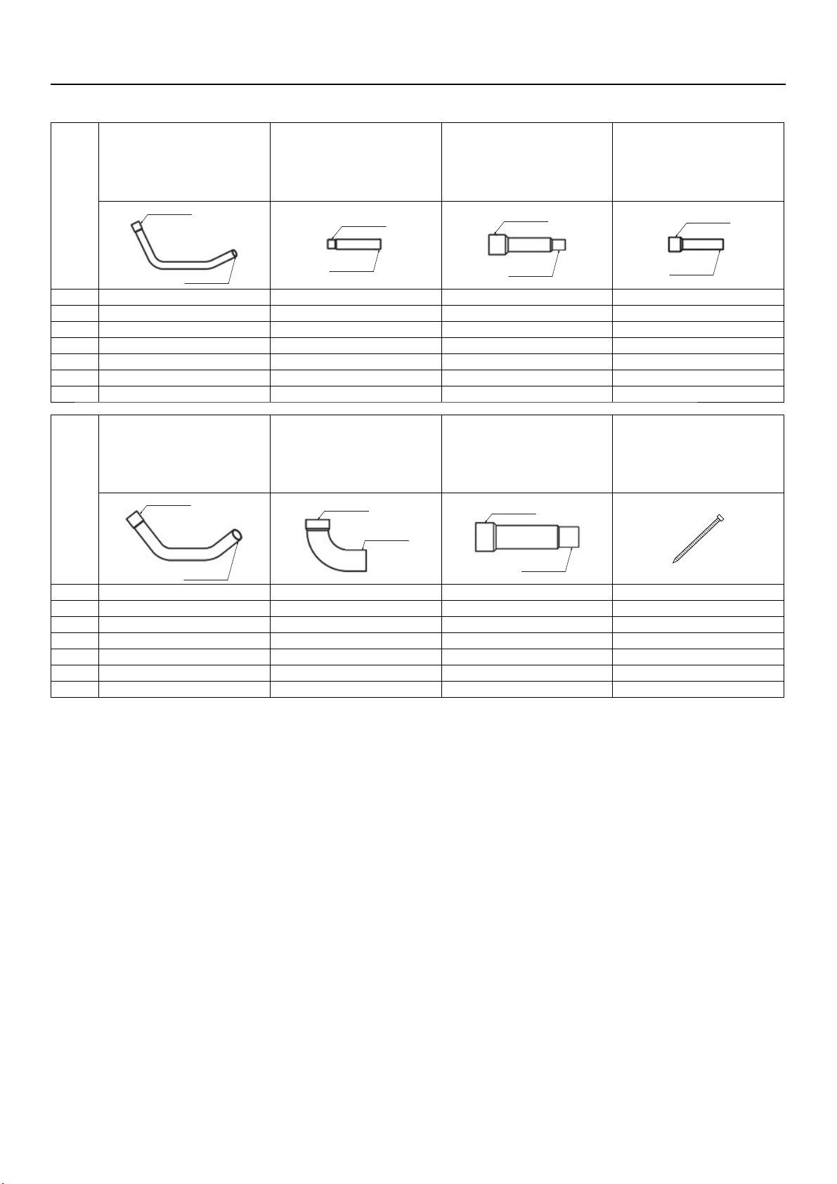
5. Package contents
The table below lists all the parts and their quantities included in the package.
①②③④
Connecting pipe
(Liquid side)
ID ø9.52 mm (ø3/8 in)
OD ø9.52 mm (ø3/8 in)
ID ø9.52
Connecting pipe
(Liquid side)
ID ø9.52 mm (ø3/8 in)
OD ø12.7 mm (ø1/2 in)
ID ø9.52
Connecting pipe
(Liquid side)
ID ø15.88 mm (ø5/8 in)
OD ø9.52 mm (ø3/8 in)
ID ø15.88
Connecting pipe
(Liquid side)
ID ø15.88 mm (ø5/8 in)
OD ø12.7 mm (ø1/2 in)
ID ø15.88
OD ø9.52
OD ø12.7
OD ø9.52
OD ø12.7
P200 1 - - P250 1 1 - P300 - - 1 1
P350 - - - 1
P400 - - - 1
P450 - - - P500 - - - -
⑤⑥⑦⑧
Connecting pipe
(Liquid side)
ID ø15.88 mm (ø5/8 in)
OD ø15.88 mm (ø5/8 in)
ID ø15.88
OD ø15.88
Connecting elbow
(Gas side)
ID ø28.58 mm (ø1-1/8 in)
OD ø28.58 mm (ø1-1/8 in)
ID ø28.58
OD ø28.58
Connecting pipe
(Gas side)
ID ø28.58 mm (ø1-1/8 in)
OD ø22.2 mm (ø7/8 in)
ID ø28.58
OD ø22.2
Tie band
P200 - 1 1 2
P250 - 1 1 2
P300 1 1 1 2
P350 1 1 - 2
P400 1 1 - 2
P450 1 1 - 2
P500 1 1 - 2
KD79S703H01
GB-10
Page 13
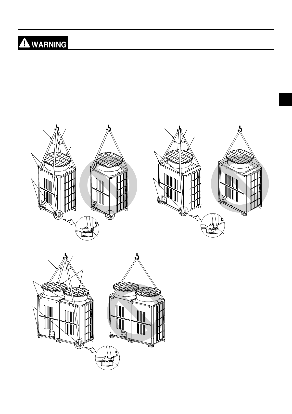
6. Transporting the unit
When lifting the unit, pass the slings through the four designated sling holes.
- Improper lifting will cause the unit to topple or fall, resulting in serious injury.
・Always use two slings to lift up the unit. Each sling must be at least 8 m (26 ft) long and must be able to support the
weight of the unit.
・Put protective pads between slings and the unit where the slings touch the unit at the base to protect the unit from
being scratched.
・Put 50 mm (2 in) or thicker protective pads between slings and the unit where the slings touch the unit at the top of
the unit to protect the unit from being scratched and to avoid contact with the slings and the fan guard.
・Make sure that the angles between slings at the top are less than 40 degrees.
P200 to P250 P300 to P400
Ⓐ
≤ 40°
Ⓐ
≤ 40°
Ⓔ
GB
Ⓑ
Ⓒ
P450 to P500
Ⓐ
Ⓑ
Ⓔ
≤ 40°
Ⓑ
Ⓒ
Ⓓ
Ⓐ Slings (Min. 8 m (26 ft) x 2)
Ⓑ Protective pads (Minimum thickness: 50 mm
Ⓔ
(2 in))
(two each in the front and back)
Ⓒ Protective pads
(two each in the front and back)
Ⓓ Sling holes
(two each in the front and back)
Ⓔ Fan guard
Ⓓ
Ⓒ
KD79S703H01
Ⓓ
GB-11
Page 14
7. Installation location
Do not install the unit where combustible gas may leak.
- If combustible gas accumulates around the unit, fire or explosion may result.
・Provide sufficient space around the unit for effective operation, efficient air movement, and ease of access for
maintenance.
・Note that refrigerant gas is heavier than air and will therefore tend to collect in low spots such as basements.
・When an indoor unit that draws in outside air exits near the outdoor unit, be careful not to affect the normal
operation of the indoor unit.
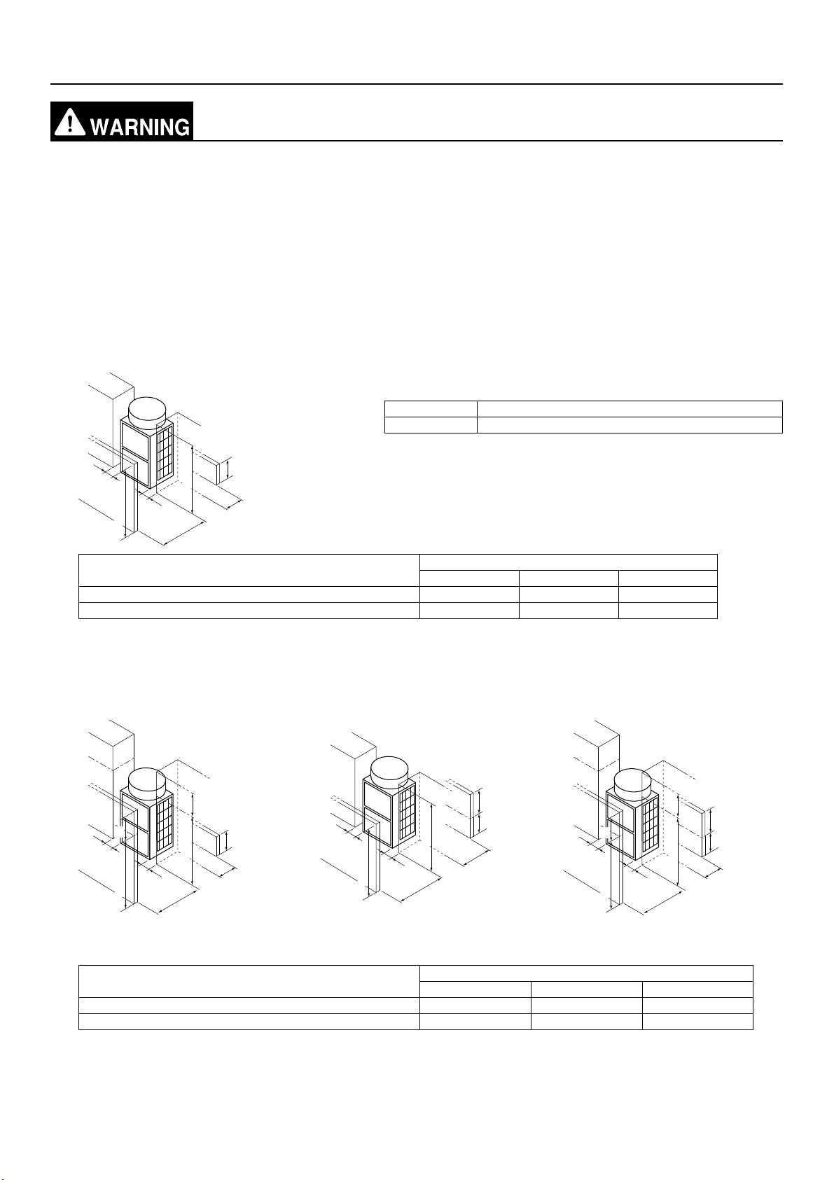
7-1. Single unit installation
(1) When all walls are within their height limits*.
* Height limit
Front/Right/Left Same height or lower than the overall height of the unit
Rear 500 mm (19-11/16 in) or lower from the unit bottom
[mm (in)]
L3
≤ Unit height
L3
≤ Unit height
When the distance behind the unit (L2) needs to be small 450 (17-3/4) 100 (3-15/16) 50 (2)
When the distance to the right or left (L3) needs to be small 450 (17-3/4) 300 (11-13/16) 15 (5/8)
L1
≤ 500 (19-11/16)
L2
Required minimum distance [mm (in)]
L1 (Front) L2 (Rear) L3 (Right/Left)
(2) When one or more walls exceed their height limits*.
When the wall(s) at the front and/
or the right/left exceed(s) their
When the wall at the rear exceeds
its height limit
When all walls exceed their height
limits
height limits
h3
h1
L3
Unit height
L3
Unit height
L1
≤ 500
(19-11/16)
L2
L3
≤ Unit height
L3
≤ Unit height
L1
h2
500
(19-11/16)
L2
h1
L3
Unit height
h3
h2
500
(19-11/16)
Unit height
L3
L1
L2
Add the dimension that exceeds the height limit (shown as "h1" through "h3" in the figures) to L1, L2, and L3 as
shown in the table below.
Required minimum distance [mm (in)]
L1 (Front) L2 (Rear) L3 (Right/Left)
When the distance behind the unit (L2) needs to be small 450 (17-3/4) + h1 100 (3-15/16) + h2 50 (2) + h3
When the distance to the right or left (L3) needs to be small 450 (17-3/4) + h1 300 (11-13/16) + h2 15 (5/8) + h3
KD79S703H01
GB-12
Page 15
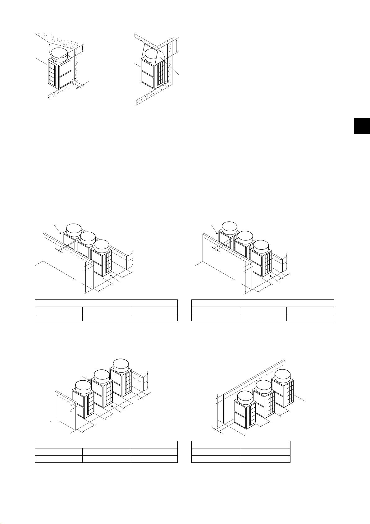
(3) When there are overhead obstacles
≥ 45°
≥ 240 (9-1/2)
≥ 50 (2)
≥ 1000 (39-3/8)
Air outlet guide
(not supplied)
7-2. Multiple unit installation
・When installing multiple units, make sure to take into consideration factors such as providing enough space for
people to pass through, ample space between blocks of units, and sufficient space for airflow. (The areas marked
with Ⓐ in the figures below must be left open.)
・In the same way as with the single unit installation, add the dimension that exceeds the height limit (shown as "h1"
through "h3" in the figures) to L1, L2, and L3 as shown in the tables below.
・If there are walls in the front and rear of the block of units, up to six units (three units for units P450 through P500)
can be installed consecutively side by side, and a space of 1000 mm (39-3/8 in) or more must be left between each
block of six units.
(1) Side-by-side installation
When the distances between the units (L4) need to
be small
Ⓐ
When the distance behind the block of units (L2) needs
to be small
Ⓐ
GB
L4
h1
Unit height
L1
h2
500 (19-11/16)
L2
Ⓐ
Required minimum distance [mm (in)]
L1 (Front) L2 (Rear) L4 (Between)
450 (17-3/4) + h1 300 (11-13/16) + h2 30 (1-3/16)
(2) Face-to-face installation
When there are walls in the front and rear of the
block of units
Ⓐ
L4
Ⓐ
Unit height
h1
L4
L1
h2
500 (19-11/16)
L2
L4
h2
L2
Ⓐ
500 (19-11/16)
h1
Unit height
L1
Required minimum distance [mm (in)]
L1 (Front) L2 (Rear) L4 (Between)
450 (17-3/4) + h1 100 (3-15/16) + h2 100 (3-15/16)
When there is a wall on either the right or left side of the
block of units
h3
Unit height
L4
L3
L4
Required minimum distance [mm (in)]
L1 (Front) L2 (Rear) L4 (Between)
450 (17-3/4) + h1 100 (3-15/16) + h2 450 (17-3/4)
KD79S703H01
Required minimum distance [mm (in)]
L3 (Right/Left) L4 (Between)
15 (5/8) + h3 450 (17-3/4)
GB-13
Page 16
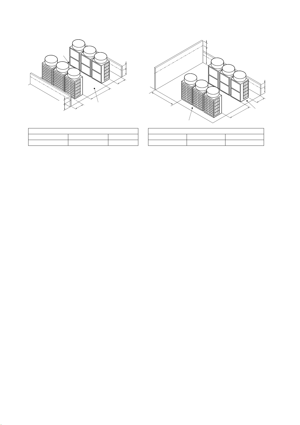
(3) Combination of face-to-face and side-by-side installations
When there are walls in the front and rear of the
When there are two walls in an L-shape
block of units
Ⓐ
h2
500
(19-11/16)
h3
Unit height
L2
L4
500 (19-11/16)
h2’
L2’
Ⓐ
Required minimum distance [mm (in)]
L2 (Right) L2' (Left) L4 (Between)
300 (11-13/16) + h2 300 (11-13/16) + h2' 900 (35-7/16)
Ⓐ Leave open in two directions.
L3
L4
Ⓐ
Required minimum distance [mm (in)]
L2 (Right) L3 (Right/Left) L4 (Between)
300 (11-13/16) + h2 1000 (39-3/8) + h3 900 (35-7/16)
h2
500
(19-11/16)
L2
Ⓐ
KD79S703H01
GB-14
Page 17
8. Foundation work
Install the unit in accordance with the instructions to minimize the risk of damage from
earthquakes and strong winds.
- Improper installation will cause the unit to topple, resulting in serious injury.
The unit must be securely installed on a structure that can sustain its weight.
- Failure to do so will cause the unit to fall, resulting in serious injury.
・When performing the foundation work, make sure that the floor surface has sufficient strength and carefully route
pipes and wires in consideration of the water drainage that will be required when the unit is operated.
・If considering routing the pipes and wires across the bottom of the unit, make sure that the base is at least 100 mm
(3-15/16 in) high so that the through-holes will not be blocked.
・Provide a strong base of concrete or angle iron. If a stainless steel base is used, insulate the area between the
base and the outdoor unit by putting a rubber cushion or by applying an electrically insulated coating to prevent the
base from rusting.
・Install the unit on a level surface.
・With some types of installation, unit vibration and sound will be transmitted to the floors and walls. In such locations,
take measures to prevent vibration (such as using anti-vibration rubber pads).
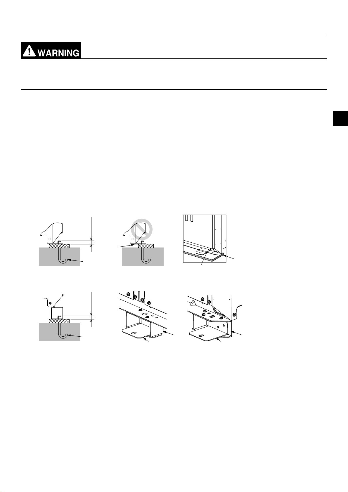
[mm (in)]
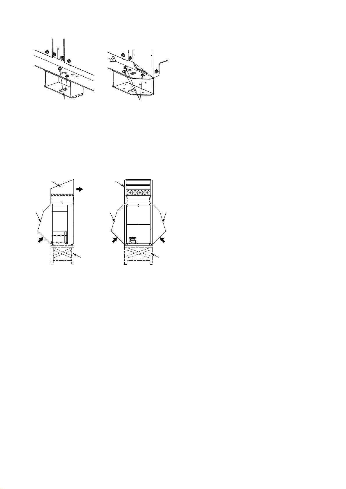
(1) Without a detachable leg
≤ 30 (1-3/16)≤ 30 (1-3/16)
Ⓑ
Ⓐ
Ⓒ
Ⓓ
(2) With a detachable leg
GB
Ⓐ
ⒸⒸ
Ⓐ M10 anchor bolt (not supplied)
Ⓑ (Incorrect installation) The corner section is not securely received.
Ⓒ Fixing bracket for post-installed anchor bolts (not supplied) (To be fixed with three screws)
Ⓓ Anti-vibration rubber pad
(The pad needs to be large enough to cover the entire width of each unit leg.)
Ⓔ Detachable leg
ⒺⒺ
・Make sure that the corner section is securely received. If not, the unit legs could bend.
・The length of the projecting part of the anchor bolt should be 30 mm (1-3/16 in) or less.
・This unit is not designed to be anchored with post-installed anchor bolts unless fixing brackets are installed at
the bottom four locations (six locations for units P450 through P500).
KD79S703H01
GB-15
Page 18
・To remove the detachable legs on site, unscrew the screws shown in the figure below. If the unit leg coating is
damaged when the detachable leg is removed, repair the coating on site.
Ⓐ Screws
Ⓐ
Ⓐ
・In abnormally harsh environments such as cold and/or windy areas, sufficient countermeasures to guard against
excessive wind and snow should be taken to ensure the unit’s correct operation. When the unit is expected to
operate in cooling mode in conditions under 10°C (50°F), in snowy areas, in environments subject to strong
winds or rain, install snow hoods of the following specifications (not supplied) as shown in the figure below.
Material: Galvanized steel plate 1.2T
Painting: Overall painting with polyester powder
Color: Munsell 3.0Y 7.8/1.1 (same as the unit color)
Size: Refer to the Data Book.
ⒸⒸ
Ⓐ
Ⓒ
ⒷⒷ
ⒹⒹ
Ⓒ
Ⓐ Outlet
Ⓑ Inlet
Ⓒ Snow hood
Ⓓ Raised base
Ⓒ
Ⓑ
・Install the unit so that the wind will not blow directly against the inlet and outlet.
・If necessary, install the unit on a raised base of the following specifications (not supplied) to prevent damage
from snow.
Material: Angle iron (Build a structure that snow and wind can pass through.)
Height: Expected maximum snowfall plus 200 mm (7-7/8 in)
Width: Within the unit width (If the raised base is too wide, snow will accumulate on the raised base.)
・When the unit is used in a cold region and the heating operation is continuously performed for a long time when
the outside air temperature is below freezing, install a heater on the raised base or take other appropriate
measures to prevent water from freezing on the raised base.
KD79S703H01
GB-16
Page 19
9. Refrigerant piping work
Do not use any refrigerant other than the type indicated in the manuals for the unit and on
the nameplate.
- Doing so will cause the unit or pipes to burst, or result in an explosion or fire during use, during
repairs, or at the time of disposal of the unit.
- It may also be in violation of applicable laws.
- MITSUBISHI ELECTRIC CORPORATION cannot be held responsible for malfunctions or
accidents resulting from the use of the wrong type of refrigerant.
After the installation has been completed, check for refrigerant leaks.
- If the refrigerant leaks, oxygen starvation may result. If the leaked refrigerant comes in contact
with a heat source, toxic gas will be generated.
Use the following tools specifically designed for use with the specified refrigerant: Gauge
manifold, charge hose, gas leak detector, check valve, refrigerant charge base, vacuum
gauge, and refrigerant recovery equipment.
- Gas leak detectors for conventional refrigerants will not react to a refrigerant that does not
contain chlorine.
- If the specified refrigerant is mixed with water, refrigerant oil, or another refrigerant, the
refrigerant oil will deteriorate and the compressor will malfunction.
GB
Do not use existing refrigerant piping.
- The old refrigerant and refrigerant oil in the existing piping contain a large amount of chlorine,
which will cause the refrigerant oil in the new unit to deteriorate and cause the compressor to
malfunction.
9-1. Restrictions
・Existing refrigerant piping must not be used because the design pressure for systems using R410A is higher than
that for systems using other types of refrigerants.
・Do not install outdoor unit piping when it is raining.
・Do not use special detergents for washing piping.
・Always observe the restrictions on refrigerant piping (such as pipe size, pipe length, and vertical separation
distance) to prevent equipment failure or a decline in heating/cooling performance.
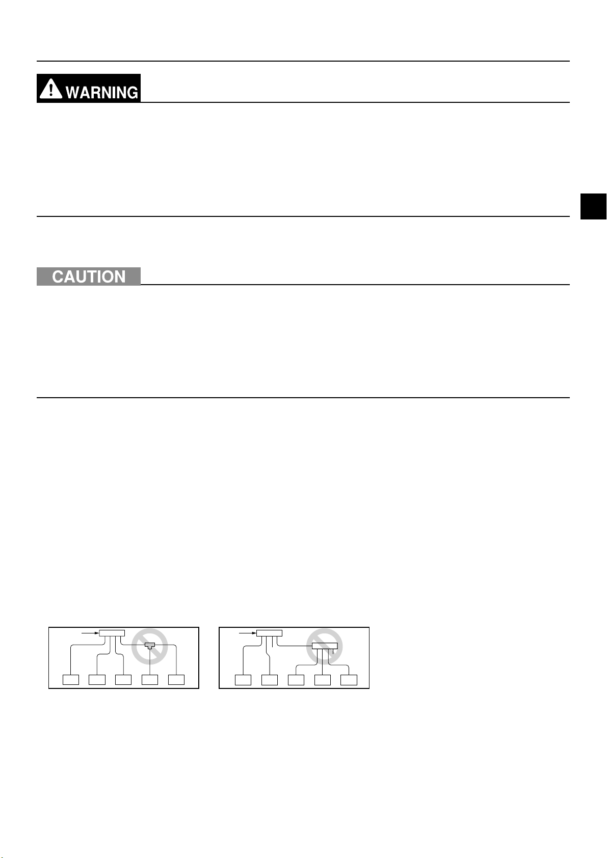
・Do not install solenoid valves to prevent oil backflow and compressor start-up failure.
・Do not install a sight glass because it may show improper refrigerant flow. If a sight glass is installed, inexperienced
technicians that use the glass may overcharge the refrigerant.
・Branching cannot be made after header branching.
ⒶⒶ
Ⓑ
ⒸⒸⒸ ⒸⒸ Ⓒ ⒸⒸⒸⒸ
Ⓑ
Ⓐ From outdoor unit
Ⓑ Cap
Ⓒ Indoor unit
KD79S703H01
GB-17
Page 20
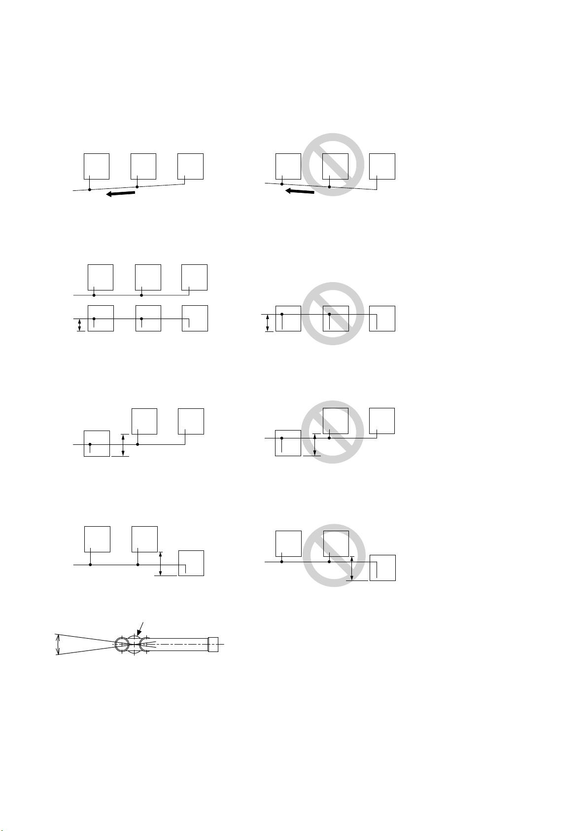
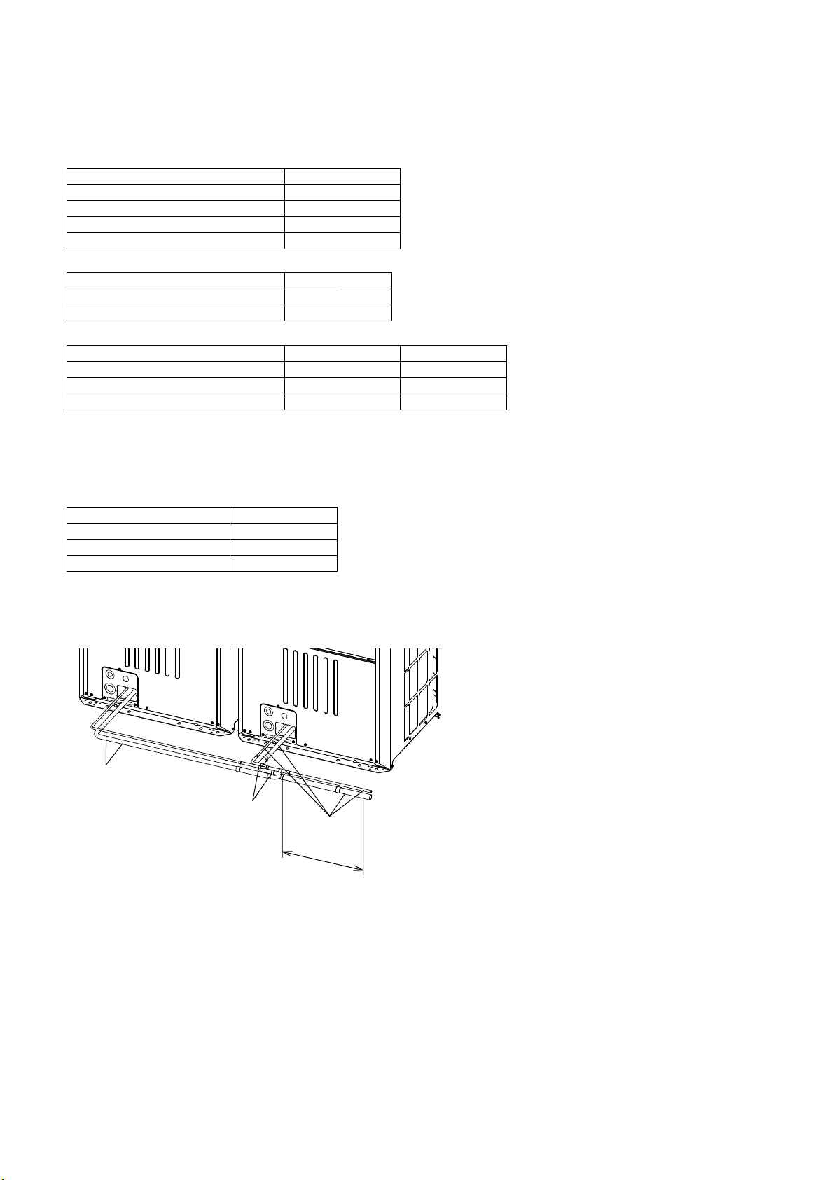
・The pipe from multiple outdoor units must be installed so that oil will not accumulate in the pipe under certain
conditions. Refer to the figures below for details.
* Small dots in the figures indicate branching points.
Ⓐ To indoor units
(1) The pipe from the outdoor units must be inclined downward to the indoor unit side. In the figure on the right,
because the pipe is inclined upward, the oil in the pipe accumulates when Unit 1 is in operation and Unit 3 is
stopped.
Unit 1 Unit 3Unit 2Unit 1
Ⓐ
Unit 2
Unit 3
Ⓐ
(2) The distance between the unit bottom and the pipe (H) must be 0.2 m (7-7/8 in) or below. In the figure on the
right, because the distance is more than 0.2 m (7-7/8 in), the oil accumulates in Units 1 and 2 when Unit 3 is in
operation and Units 1 and 2 are stopped.
Unit 1
Ⓐ
Unit 1
Ⓐ
H
H ≤ 0.2 m (7-7/8 in)
Unit 2
Unit 2
Unit 3
Unit 3
Ⓐ
H
H > 0.2 m (7-7/8 in)
Unit 2Unit 1
Unit 3
(3) The vertical separation between units (H) must be 0.1 m (3-15/16 in) or below. In the figure on the right,
because the distance is more than 0.1 m (3-15/16 in), the oil accumulates in Unit 1 when Unit 3 is in operation
and Unit 1 is stopped.
Unit 2
Unit 1
Ⓐ
H
H ≤ 0.1 m (3-15/16 in)
Unit 3
Unit 1
Ⓐ
H
Unit 3Unit 2
H > 0.1 m (3-15/16 in)
(4) The vertical separation between units (H) must be 0.1 m (3-15/16 in) or below. In the figure on the right,
because the distance is more than 0.1 m (3-15/16 in), the oil accumulates in Unit 3 when Unit 1 is in operation
and Unit 3 is stopped.
Unit 1
Ⓐ
Unit 2
H
H ≤ 0.1 m (3-15/16 in)
Unit 3
Unit 1
Ⓐ
Unit 2
Unit 3
H
H > 0.1 m (3-15/16 in)
・Make sure that the inclination tolerance of the Twinning Kit is ±15˚ to the ground to avoid unit damage.
Ⓐ
±15°
Ⓐ Twinning Kit
KD79S703H01
GB-18
Page 21
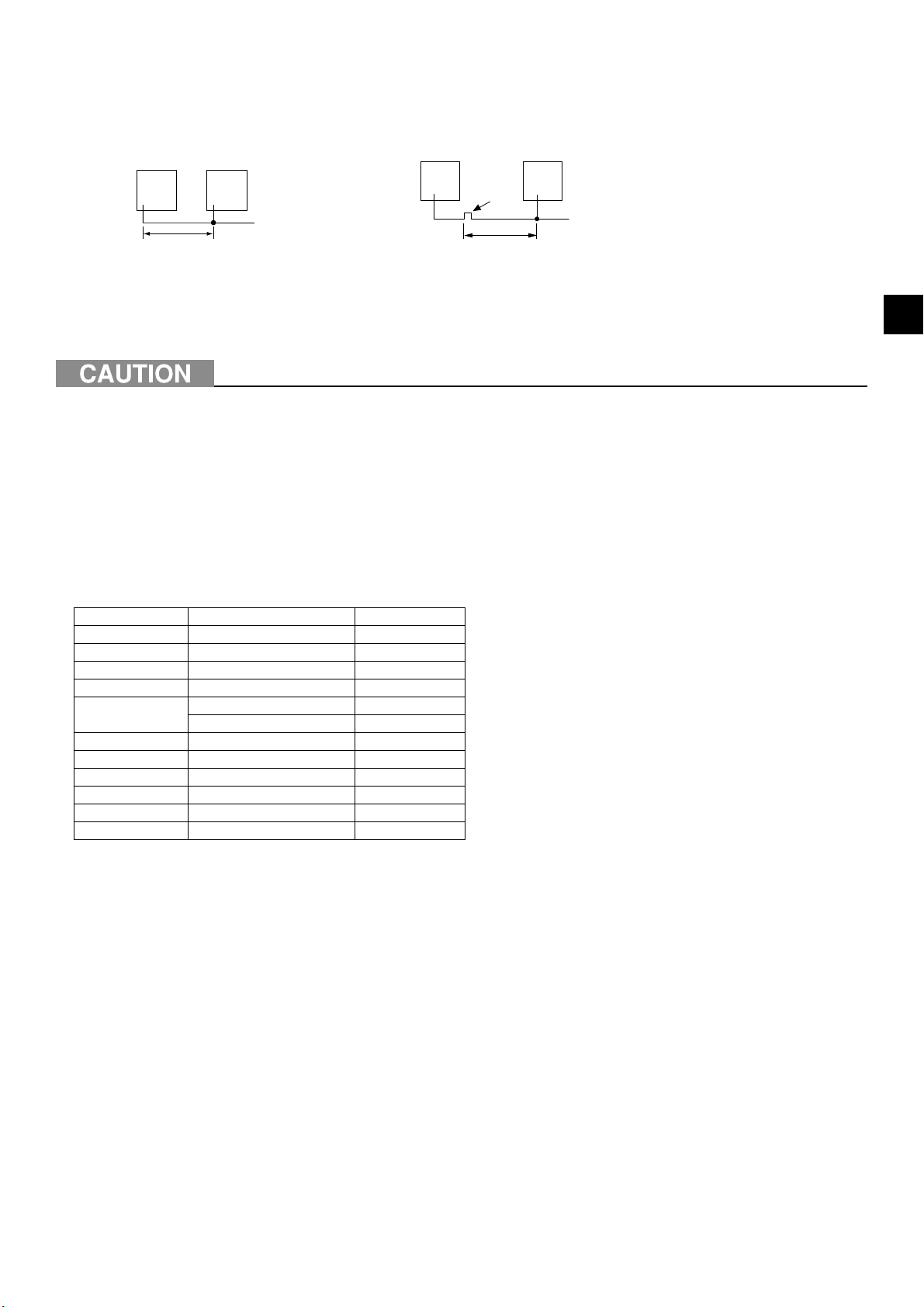
・If the length of the pipe between the branching point and the outdoor unit exceeds 2 m (6 ft), provide a trap within 2
m (6 ft) from the branching point.
The trap must be at least 200 mm (7-7/8 in) in height. (gas pipe only) If there is no trap, oil can accumulate inside
the pipe, causing a shortage of oil and may damage the compressor.
* Small dots in the figures indicate branching points.
Ⓑ
2 m (6 ft)
Ⓐ To indoor units
Ⓑ Trap (gas pipe only)
Ⓒ Gas pipe
Ⓐ
Ⓒ
≤ 2 m (6 ft)
Ⓐ
9-2. Pipe selection
Use refrigerant piping made of phosphorus deoxidized copper (copper and copper alloy
seamless pipes) that meets local requirements. Pipe joints should also meet local
requirements. Keep the inner and outer surfaces of the pipes clean and free of sulphur,
oxides, dust/dirt, shaving particles, oils, moisture, or any other contaminants.
- Contaminants on the inside of the refrigerant piping will cause the refrigerant oil to deteriorate
and cause the compressor to malfunction.
GB
Use refrigerant pipes for use with R410A refrigerant system. Piping for systems for use with other types of refrigerants
may not be able to be used.
Use refrigerant pipes with the thicknesses specified in the table below.
Size [mm (in)] Radial thickness [mm (mil)] Type
ø6.35 (ø1/4) 0.8 (32) Type-O
ø9.52 (ø3/8) 0.8 (32) Type-O
ø12.7 (ø1/2) 0.8 (32) Type-O
ø15.88 (ø5/8) 1.0 (40) Type-O
ø19.05 (ø3/4)
ø22.2 (ø7/8) 1.0 (40) Type-1/2H or H
ø25.4 (ø1) 1.0 (40) Type-1/2H or H
ø28.58 (ø1-1/8) 1.0 (40) Type-1/2H or H
ø31.75 (ø1-1/4) 1.1 (44) Type-1/2H or H
ø34.93 (ø1-3/8) 1.2 (48) Type-1/2H or H
ø41.28 (ø1-5/8) 1.4 (56) Type-1/2H or H
1.2 (48) Type-O
1.0 (40) Type-1/2H or H
KD79S703H01
GB-19
Page 22
9-3. Twinning kit selection
9-3-1. Indoor unit twinning kit
Select a proper indoor unit twinning kit (sold separately) based on the total capacity of the downstream indoor units,
using the table below as a reference.
Line branching
Total capacity of downstream indoor units Kit model
200 or below CMY-Y102SS-G2
201 to 400 CMY-Y102LS-G2
401 to 650 CMY-Y202S-G2
651 or above CMY-Y302S-G2
Line branching for the 1st branching point
Outdoor unit model Kit model
P450 to P650 CMY-Y202S-G2
P700 to P1350 CMY-Y302S-G2
Header branching
Total capacity of downstream indoor units Number of branches Kit model
200 or below 4 CMY-Y104-G
400 or below 8 CMY-Y108-G
650 or below 10 CMY-Y1010-G
* Use an adapter, if necessary, to connect a refrigerant pipe to a twinning pipe of a different diameter.
9-3-2. Outdoor unit twinning kit
Select a proper outdoor unit twinning kit (sold separately) based on the total capacity of the outdoor units, using the
table below as a reference.
Total capacity of outdoor units Kit model
P400 to P650 CMY-Y100VBK3
P700 to P900 CMY-Y200VBK2
P950 to P1350 CMY-Y300VBK3
9-4. Pipe connection example
・Example of pipe connection between outdoor units
Ⓐ
Ⓑ
Ⓐ
Ⓒ
Ⓐ On-site piping
Ⓑ Twinning Kit
Ⓒ The pipe section before the twinning pipe must
have at least 500 mm (19-11/16 in) of straight
section.
KD79S703H01
GB-20
Page 23
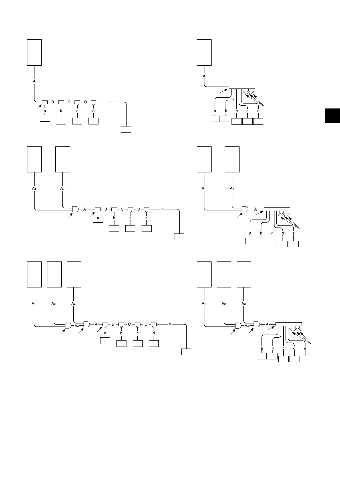
・Example of pipe connection between outdoor units and indoor units
P200 to P500YKB-A1
Unit 1
Unit 1
Ⓐ
Ⓑ
Ⓒ
Ⓒ Ⓒ Ⓒ
Ⓒ
Ⓐ
Ⓑ
Ⓒ Ⓒ
P400 to P650YSKB-A1
Unit 1 Unit 2
Ⓐ Ⓐ Ⓐ Ⓐ
Ⓔ
Ⓑ
Ⓒ
ⒸⒸⒸ
Ⓒ
Unit 1 Unit 2
Ⓕ
Ⓒ Ⓒ Ⓒ
Ⓔ
Ⓑ
ⒸⒸ
Ⓓ
GB
Ⓓ
ⒸⒸⒻⒸ
P950 to P1350YSKB-A1
Unit 1 Unit 2 Unit 3
Ⓐ Ⓐ Ⓐ Ⓐ Ⓐ Ⓐ
Ⓔ
Ⓔ
Ⓑ
Ⓒ
Ⓒ Ⓒ Ⓒ
Unit 1 Unit 2 Unit 3
Ⓔ
Ⓒ
Ⓐ Outdoor unit
Ⓑ 1st branching
Ⓒ Indoor unit
Ⓓ Cap
Ⓔ Outdoor unit twinning kit
Ⓕ Header branching
* The total length of A
1, A2, A3, and A4 is less than 10 m (32 ft).
Ⓔ
Ⓑ
ⒸⒸ
Ⓕ
Ⓓ
ⒸⒸⒸ
KD79S703H01
GB-21
Page 24

Pipes A, A1, A2, A3, A4 [mm]
Unit model
Combination unit Pipe A Pipe A1*
3
Unit 1 Unit 2 Unit 3 Liquid Gas Liquid Gas Liquid Gas Liquid Gas Liquid Gas
Pipe A2*
3
Pipe A3*
3
Pipe A4
P200YKB-A1 - - - ø9.52 ø22.2 - - - - - - - -
1
P250YKB-A1 - - - ø9.52*
P300YKB-A1 - - - ø9.52*
ø22.2 - - - - - - - -
2
ø22.2 - - - - - - - P350YKB-A1 - - - ø12.7 ø28.58 - - - - - - - P400YKB-A1 - - - ø12.7 ø28.58 - - - - - - - P450YKB-A1 - - - ø15.88 ø28.58 - - - - - - - P500YKB-A1 - - - ø15.88 ø28.58 - - - - - - - P400YSKB-A1 P200 P200 - ø12.7 ø28.58 ø9.52 ø22.2 ø9.52 ø22.2 - - - P450YSKB-A1 P250 P200 - ø15.88 ø28.58 ø9.52 ø22.2 ø9.52 ø22.2 - - - P500YSKB-A1 P250 P250 - ø15.88 ø28.58 ø9.52 ø22.2 ø9.52 ø22.2 - - - P550YSKB-A1
P300 P250 - ø15.88 ø28.58 ø12.7 ø22.2 ø9.52 ø22.2 - - - P600YSKB-A1 P350 P250 - ø15.88 ø28.58 ø12.7 ø28.58 ø9.52 ø22.2 - - - P650YSKB-A1 P350 P300 - ø15.88 ø28.58 ø15.88 ø28.58 ø9.52 ø22.2 - - - P700YSKB-A1 P350 P350 - ø19.05 ø34.93 ø15.88 ø28.58 ø15.88 ø28.58 - - - P750YSKB-A1 P400 P350 - ø19.05 ø34.93 ø15.88 ø28.58 ø15.88 ø28.58 - - - P800YSKB-A1 P450 P350 - ø19.05 ø34.93 ø15.88 ø28.58 ø15.88 ø28.58 - - - P850YSKB-A1 P450 P400 - ø19.05 ø41.28 ø15.88 ø28.58 ø15.88 ø28.58 - - - P900YSKB-A1 P450 P450 - ø19.05 ø41.28 ø15.88 ø28.58 ø15.88 ø28.58 - - - P950YSKB-A1 P400 P300 P250 ø19.05 ø41.28 ø15.88 ø28.58 ø12.7 ø22.2 ø12.7 ø22.2 ø19.05 ø34.93
P1000YSKB-A1 P400 P300 P300 ø19.05 ø41.28 ø15.88 ø28.58 ø12.7 ø22.2 ø12.7 ø22.2 ø19.05 ø34.93
P1050YSKB-A1 P400 P350 P300 ø19.05 ø41.28 ø15.88 ø28.58 ø12.7 ø28.58 ø12.7 ø22.2 ø19.05 ø34.93
P1100YSKB-A1 P400 P350 P350 ø19.05 ø41.28 ø15.88 ø28.58 ø12.7 ø28.58 ø12.7 ø28.58 ø19.05 ø34.93
P1150YSKB-A1 P450 P350 P350 ø19.05 ø41.28 ø15.88 ø28.58 ø15.88 ø28.58 ø15.88 ø28.58 ø19.05 ø34.93
P1200YSKB-A1 P450 P400 P350 ø19.05 ø41.28 ø15.88 ø28.58 ø15.88 ø28.58 ø15.88 ø28.58 ø19.05 ø34.93
P1250YSKB-A1 P450 P450 P350 ø19.05 ø41.28 ø15.88 ø28.58 ø15.88 ø28.58 ø15.88 ø28.58 ø19.05 ø34.93
P1300YSKB-A1 P450 P450 P400 ø19.05 ø41.28 ø15.88 ø28.58 ø15.88 ø28.58 ø15.88 ø28.58 ø19.05 ø34.93
P1350YSKB-A1
P450 P450 P450 ø19.05 ø41.28 ø15.88 ø28.58 ø15.88 ø28.58 ø15.88 ø28.58 ø19.05 ø34.93
Pipes A, A1, A2, A3, A4 [in]
Unit model
Combination unit Pipe A Pipe A
3
1*
Unit 1 Unit 2 Unit 3 Liquid Gas Liquid Gas Liquid Gas Liquid Gas Liquid Gas
Pipe A2*
3
Pipe A3*
3
Pipe A4
P200YKB-A1 - - - ø3/8 ø7/8 - - - - - - - -
1
P250YKB-A1 - - - ø3/8*
P300YKB-A1 - - - ø3/8*
ø7/8 - - - - - - - -
2
ø7/8 - - - - - - - P350YKB-A1 - - - ø1/2 ø1-1/8 - - - - - - - P400YKB-A1 - - - ø1/2 ø1-1/8 - - - - - - - P450YKB-A1 - - - ø5/8 ø1-1/8 - - - - - - - P500YKB-A1 - - - ø5/8 ø1-1/8 - - - - - - - P400YSKB-A1 P200 P200 - ø1/2 ø1-1/8 ø3/8 ø7/8 ø3/8 ø7/8 - - - P450YSKB-A1 P250 P200 - ø5/8 ø1-1/8 ø3/8 ø7/8 ø3/8 ø7/8 - - - P500YSKB-A1 P250 P250 - ø5/8 ø1-1/8 ø3/8 ø7/8 ø3/8 ø7/8 - - - P550YSKB-A1 P300 P250 - ø5/8 ø1-1/8 ø1/2 ø7/8 ø3/8 ø7/8 - - - P600YSKB-A1 P350 P250 - ø5/8 ø1-1/8 ø1/2 ø1-1/8 ø3/8 ø7/8 - - - P650YSKB-A1 P350 P300 - ø5/8 ø1-1/8 ø5/8 ø1-1/8 ø3/8 ø7/8 - - - P700YSKB-A1 P350 P350 - ø3/4 ø1-3/8 ø5/8 ø1-1/8 ø5/8 ø1-1/8 - - - P750YSKB-A1 P400 P350 - ø3/4 ø1-3/8 ø5/8 ø1-1/8 ø5/8 ø1-1/8 - - - P800YSKB-A1 P450 P350 - ø3/4 ø1-3/8 ø5/8 ø1-1/8 ø5/8 ø1-1/8 - - - P850YSKB-A1 P450 P400 - ø3/4 ø1-5/8 ø5/8 ø1-1/8 ø5/8 ø1-1/8 - - - P900YSKB-A1 P450 P450 - ø3/4 ø1-5/8 ø5/8 ø1-1/8 ø5/8 ø1-1/8 - - - P950YSKB-A1 P400 P300 P250 ø3/4 ø1-5/8 ø5/8 ø1-1/8 ø1/2 ø7/8 ø1/2 ø7/8 ø3/4 ø1-3/8
P1000YSKB-A1 P400 P300 P300 ø3/4 ø1-5/8 ø5/8 ø1-1/8 ø1/2 ø7/8 ø1/2 ø7/8 ø3/4 ø1-3/8
P1050YSKB-A1 P400 P350 P300 ø3/4 ø1-5/8 ø5/8 ø1-1/8 ø1/2 ø1-1/8 ø1/2 ø7/8 ø3/4 ø1-3/8
P1100YSKB-A1 P400 P350 P350 ø3/4 ø1-5/8 ø5/8 ø1-1/8 ø1/2 ø1-1/8 ø1/2 ø1-1/8 ø3/4 ø1-3/8
P1150YSKB-A1 P450 P350 P350 ø3/4 ø1-5/8 ø5/8 ø1-1/8 ø5/8 ø1-1/8 ø5/8 ø1-1/8 ø3/4 ø1-3/8
P1200YSKB-A1 P450 P400 P350 ø3/4 ø1-5/8 ø5/8 ø1-1/8 ø5/8 ø1-1/8 ø5/8 ø1-1/8 ø3/4 ø1-3/8
P1250YSKB-A1 P450 P450 P350 ø3/4 ø1-5/8 ø5/8 ø1-1/8 ø5/8 ø1-1/8 ø5/8 ø1-1/8 ø3/4 ø1-3/8
P1300YSKB-A1 P450 P450 P400 ø3/4 ø1-5/8 ø5/8 ø1-1/8 ø5/8 ø1-1/8 ø5/8 ø1-1/8 ø3/4 ø1-3/8
P1350YSKB-A1 P450 P450 P450 ø3/4 ø1-5/8 ø5/8 ø1-1/8 ø5/8 ø1-1/8 ø5/8 ø1-1/8 ø3/4 ø1-3/8
*1 Use the ø12.7 (ø1/2) pipe if the piping length from the outdoor unit to the farthest indoor unit is 90 m (295 ft) or longer.
*2 Use the ø12.7 (ø1/2) pipe if the piping length from the outdoor unit to the farthest indoor unit is 40 m (131 ft) or longer.
*3 If the combination units 1, 2, and 3 are in a different order as listed in the table, make sure to use the pipes of appropriate size for the situation.
*4 If the pipe length after the first branching point exceeds 40 m (131 ft) (≤ 90 m (295 ft)), use the one size larger liquid pipe for all pipes from indoor
units to the first branch.
*5 When the vertical separation between the indoor units is 15 m (49 ft) (≤ 30 m (98 ft)), use the one size larger liquid pipe for all pipes from the
lower indoor units to the first branch.
KD79S703H01
GB-22
Page 25
Pipes B,C,D [mm (in)]
Total capacity of indoor units
140 or below ø9.52 (ø3/8) ø15.88 (ø5/8)
141 to 200 ø9.52 (ø3/8) ø19.05 (ø3/4)
201 to 300 ø9.52 (ø3/8) ø22.2 (ø7/8)
301 to 400 ø12.7 (ø1/2) ø28.58 (ø1-1/8)
401 to 650 ø15.88 (ø5/8) ø28.58 (ø1-1/8)
651 to 800 ø19.05 (ø3/4) ø34.93 (ø1-3/8)
801 or above ø19.05 (ø3/4) ø41.28 (ø1-5/8)
Pipes a,b,c,d,e [mm (in)]
Capacity index of indoor unit
20, 25, 32, 40, 50 ø6.35 (ø1/4) ø12.7 (ø1/2)
63, 71, 80, 100, 125, 140 ø9.52 (ø3/8) ø15.88 (ø5/8)
200 ø9.52 (ø3/8) ø19.05 (ø3/4)
250 ø9.52 (ø3/8) ø22.2 (ø7/8)
Liquid Gas
Pipe
Pipe
Liquid Gas
9-5. Piping connections and valve operations
Before heating the brazed sections, remove the gas and oil that are trapped in the pipes.
- Failure to do so may generate fire, resulting in serious injury.
GB
Ventilate the room while servicing the unit.
- If the refrigerant leaks, oxygen deficiency may result. If the leaked refrigerant comes in contact
with a heat source, toxic gas will be generated.
Store pipes indoors, and keep both ends of the pipes sealed until just before making a
flare connection or brazing. (Store elbows and other joints in plastic bags.)
- If dust, dirt, or water enters the refrigerant lines, the refrigerant oil will deteriorate and the
compressor will malfunction.
Keep the service valves closed until refrigerant charging is completed.
- Failure to do so will damage the unit.
Place a wet towel on the service valves before brazing the pipes to keep the temperature of
the valves from rising above 120ºC (248ºF).
- Failure to do so may result in equipment damage.
Keep the flame out of contact with the cables and metal sheet when brazing the pipes.
- Failure to do so may result in burnout or malfunction.
Braze the pipes with a nitrogen purge to avoid oxidation.
- Oxidized flux inside the refrigerant pipes will cause the refrigerant oil to deteriorate and cause
the compressor to malfunction.
KD79S703H01
GB-23
Page 26
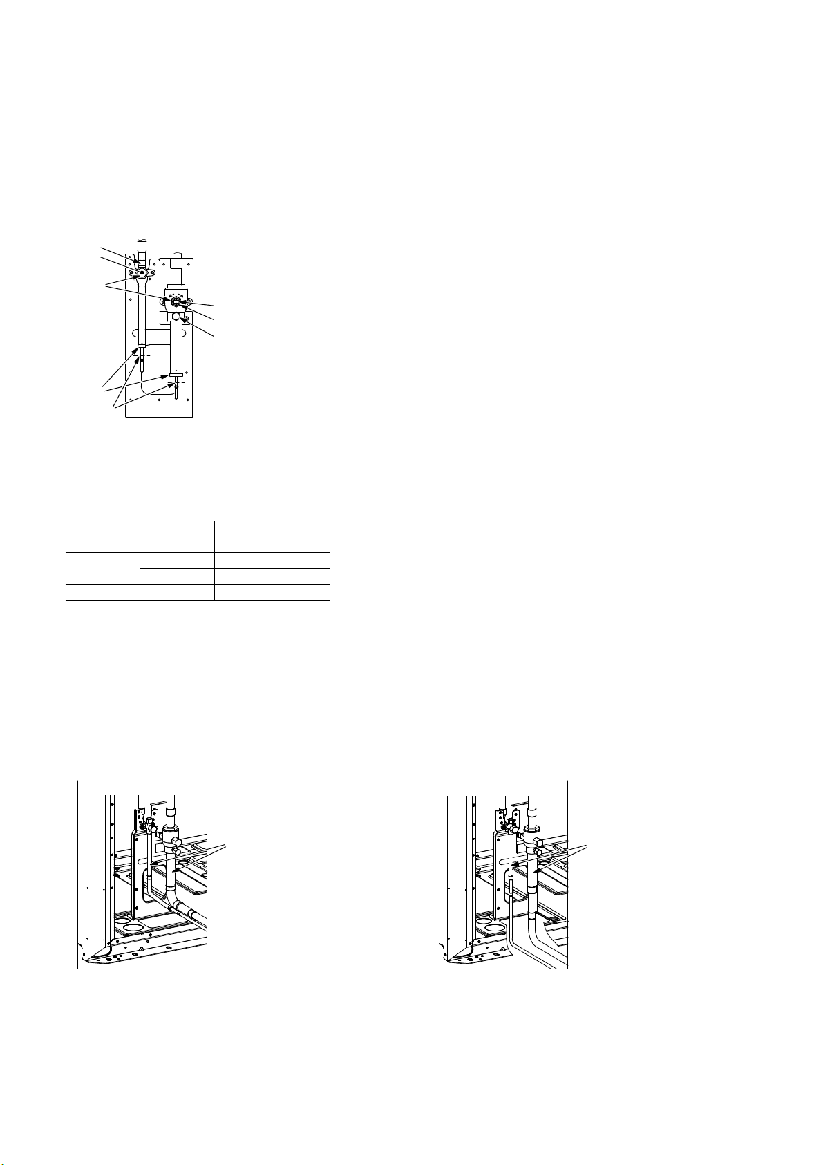
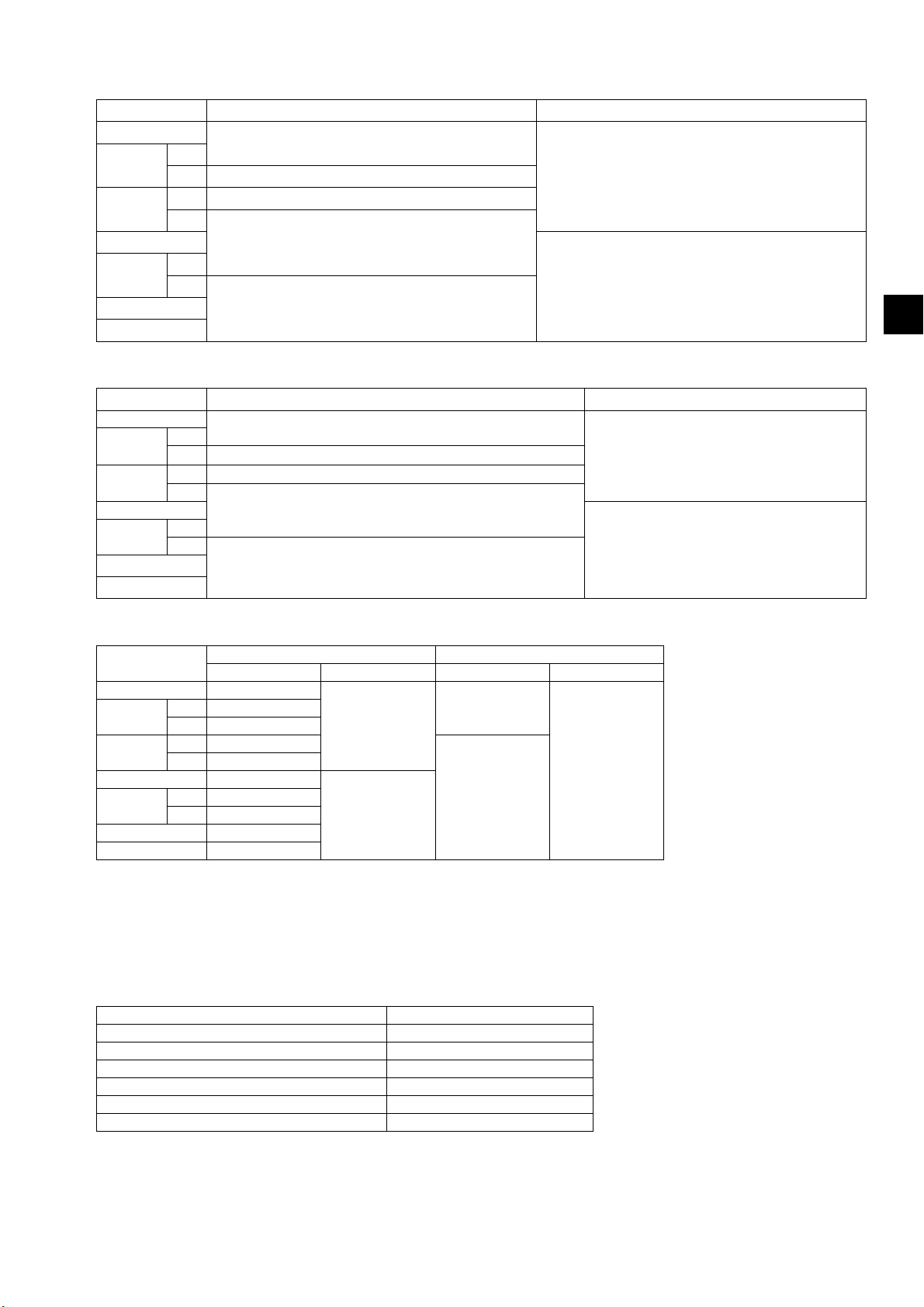
9-5-1. Removing the pinched connecting pipes
The unit is shipped with the pinched connecting pipes attached to the liquid- and gas-side service valves to prevent
gas leakage.
Take the following steps ① through ③ to remove the pinched connecting pipes before connecting refrigerant pipes to
the outdoor unit.
① Check that the service valves are fully closed (turned clockwise all the way).
② Remove the gas in the pinched connecting pipes, and drain out all the refrigerant oil. (See Ⓔ below.)
③ Remove the pinched connecting pipes. (See Ⓕ below.)
<A> Refrigerant service valve (liquid/brazed)
Ⓒ
Ⓐ
Ⓓ
Ⓕ
Ⓔ
<A> <B>
O
S
Ⓐ
Ⓑ
Ⓒ
<B> Refrigerant service valve (gas/brazed)
Ⓐ Valve shaft
The unit is shipped with the valve closed. Keep the valve closed while connecting pipes or
evacuating the system. Open the valve upon completion of this work.
Turn the shaft counterclockwise as far as it will go (90˚) to open the valve, and clockwise to close
it.
Ⓑ Stopper pin
Prevents the shaft from turning 90˚ or more.
Ⓒ Service port
Through the service ports, you can charge refrigerant, remove the gas in the pinched connecting
pipes, or evacuate the system.
Ⓓ Cap
Remove the cap before turning the shaft. Put the cap back on upon completion of all work.
Ⓔ Severed section of the pinched connecting pipe
Ⓕ Brazed section of the pinched connecting pipe
9-5-2. Connecting pipes
・The refrigerant pipe from the outdoor unit is branched at the pipe end, and each branch is then connected to an
indoor unit.
Connecting method
Indoor unit Brazed or flared
Outdoor unit
Branched section Brazed
・Refer to section 5 "Package contents" for details about the supplied connecting pipes.
・When connecting pipes, make sure the service valves are completely closed.
・Commercially available pipes often contain dust or debris. Always blow them clean with a dry inert gas.
・Take care to prevent dust, water or other contaminants from entering the pipes during installation.
・Reduce the number of bending portions as much as possible, and make the bending radius as big as possible.
・Do not use any commercially available anti-oxidizing agents since they may cause pipe corrosion and degrading of
the refrigerant oil. Please contact Mitsubishi Electric for more details.
・Make sure that the pipes are not in contact with each other, unit panels, or base plates.
(1) When routing the pipes through the front of the unit (2) When routing the pipes through the bottom of the unit
Gas pipe Brazed
Liquid pipe Brazed
<A> <B>
Ⓐ
<A> <B>
Ⓐ
<A> Liquid side
<B> Gas side
Ⓐ Refrigerant service valve piping
KD79S703H01
GB-24
Page 27
・Connecting the on-site piping and the service valve piping
When routing the pipes through the front of the unit
Liquid side Gas side
P200
P250
P300
P350
P400
P450
P500
Use the supplied connecting pipe ①.
*1
*2
Use the supplied connecting pipes ① and ②.
*3
Use the supplied connecting pipes ⑤ and ③.
*4*6
Use the supplied connecting pipes ⑤ and ④.
*5
*6
Use the supplied connecting pipe ⑤.
When routing the pipes through the bottom of the unit
Liquid side Gas side
P200
P250
P300
P350
P400
P450
P500
Expand the end of the on-site piping. (ID ø9.52 mm (ø3/8 in))
*1
*2
Use the supplied connecting pipe ②.
*3
Use the supplied connecting pipe ③.
*4*6
Use the supplied connecting pipe ④.
*5
*6
Expand the end of the on-site piping. (ID ø15.88 mm (ø5/8 in))
Use the supplied connecting elbow ⑥ and connecting
pipe ⑦.
Use the supplied connecting elbow ⑥.
GB
Use the supplied connecting pipe ⑦.
Expand the end of the on-site piping. (ID ø28.58
mm (ø1-1/8 in))
<Reference> Size of refrigerant pipes
On-site piping [mm (in)] Service valve piping [mm (in)]
Liquid Gas Liquid Gas
P200 ø9.52 (ø3/8)
P250
P300
P350 ø12.7 (ø1/2)
P400
P450 ø15.88 (ø5/8)
P500 ø15.88 (ø5/8)
*1 When the piping length from the outdoor unit to the farthest indoor unit is less than 90 m (295 ft)
*2 When the piping length from the outdoor unit to the farthest indoor unit is 90 m (295 ft) or more
*3 When the piping length from the outdoor unit to the farthest indoor unit is less than 40 m (131 ft)
*4 When the piping length from the outdoor unit to the farthest indoor unit is 40 m (131 ft) or more
*5 When the unit is used alone
*6 When the unit is used in combination with other outdoor units
*1 ø9.52 (ø3/8)
*2 ø12.7 (ø1/2)
*3 ø9.52 (ø3/8)
*4*6 ø12.7 (ø1/2)
*5 ø12.7 (ø1/2)
*6 ø15.88 (ø5/8)
ø22.2 (ø7/8)
ø28.58 (ø1-1/8)
ø9.52 (ø3/8)
ø28.58 (ø1-1/8)
ø15.88 (ø5/8)
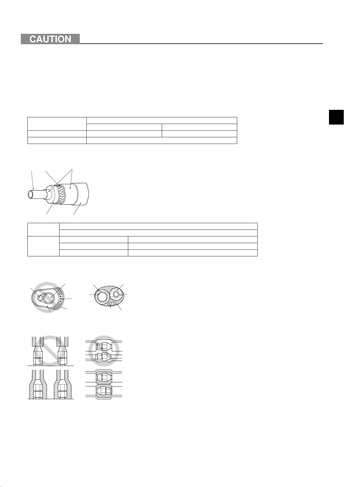
・When expanding the on-site piping, satisfy the minimum insertion depth requirement as follows.
Pipe size [mm (in)] Minimum insertion depth [mm (in)]
ø5 (ø1/4) or more, less than ø8 (ø3/8) 6 (1/4)
ø8 (ø3/8) or more, less than ø12 (ø1/2) 7 (5/16)
ø12 (ø1/2) or more, less than ø16 (ø11/16) 8 (3/8)
ø16 (ø11/16) or more, less than ø25 (ø1) 10 (7/16)
ø25 (ø1) or more, less than ø35 (ø1-7/16) 12 (1/2)
ø35 (ø1-7/16) or more, less than ø45 (ø1-13/16) 14 (9/16)
KD79S703H01
GB-25
Page 28
9-5-3. Sealing the openings around the pipes
Seal all openings around pipes and wires to keep out small animals, rainwater, or snow.
- Failure to do so may result in current leakage, electric shock, or damage to the unit.
Ⓐ Example of closure materials (not supplied)
Ⓑ Fill the openings
ⒶⒷ
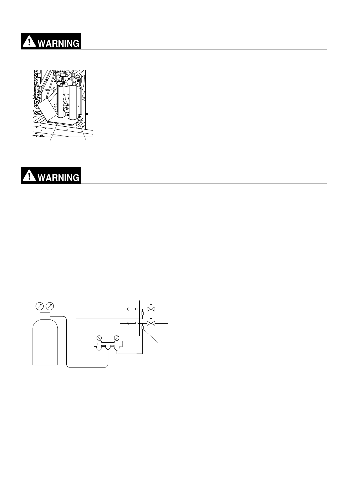
9-6. Air-tightness test
Do not use oxygen, flammable gas, or a refrigerant containing chlorine for air-tightness
testing.
- Doing so may result in an explosion. Chlorine will deteriorate the refrigerant oil.
After refrigerant pipe installation is completed, check the system for leaks by conducting an air-tightness test. If there
is a leak, the composition of the refrigerant will change and the performance will drop.
<Air-tightness test procedures>
① Make sure the service valves are closed.
② Add pressure to the refrigerant pipes through the service ports of the liquid and gas pipes.
* Pressurize to the design pressure (4.15 MPa) using nitrogen gas.
③ If the pressure holds for one day and does not decrease, the pipes have passed the test and there are no leaks.
If the pressure decreases, there is a leak. Look for the source of the leak by spraying a bubbling agent (e.g.,
Gupoflex) on the flared or brazed sections.
④ Wipe off the bubbling agent.
Ⓕ
Ⓑ
Ⓑ
Ⓒ
LO
Ⓐ
ⒹⒺ
HI
Ⓘ
Ⓙ
Ⓐ Nitrogen gas
Ⓑ To indoor unit
Ⓖ
Ⓒ Gauge manifold
Ⓓ Low pressure knob
Ⓗ
Ⓔ High pressure knob
Ⓕ Service valve
Ⓖ Liquid piping
Ⓗ Gas piping
Ⓘ Outdoor unit
Ⓙ Service port
KD79S703H01
GB-26
Page 29
9-7. Thermal insulation for pipes
Insulate pipes to prevent condensation.
- Condensation may collect and drip from the unit onto the ceiling or floor.
Insulate the liquid and gas pipes separately with polyethylene foam insulation materials. Inadequate insulation may
cause condensation to drip. Pipes in the ceiling are especially vulnerable to condensation and require adequate
insulation.
9-7-1. Insulation material
・Check that the insulation materials meet the standards in the table below.
Pipe size [mm (in)]
ø6.35 (ø1/4)–ø25.4 (ø1) ø28.58 (ø1-1/8)–ø41.28 (ø1–5/8)
Thickness [mm (in)] Min. 10 (7/16) Min. 15 (5/8)
Heat resistance Min. 120°C (248°F)
* The insulation thickness may need to be increased in high-temperature/humidity conditions.
* Even when specifications are defined by your client, the standards in the table should be met.
Ⓑ
Ⓐ
Ⓓ
Insulation
material A
Outer
covering B
* If a polyethylene cover is used as an outer covering, asphalt roofing is not necessary.
Ⓒ
Ⓔ
Glass fiber + Steel wire
Adhesive + Heat-resistant polyethylene foam + Adhesive tape
Indoor Vinyl tape
Under the floor and exposed Waterproof hemp cloth + Bronze asphalt
Outdoor Waterproof hemp cloth + Zinc plate + Oily paint
Ⓐ Steel wire
Ⓑ Pipe
Ⓒ Oily mastic asphalt or asphalt
Ⓓ Insulation material A
Ⓔ Outer covering B
・Do not insulate the electric wires.
Ⓐ
Ⓑ
Ⓒ
Ⓔ
Ⓓ
Ⓔ
Ⓑ
Ⓔ
Ⓒ
Ⓓ
Ⓐ Liquid pipe
Ⓑ Gas pipe
Ⓐ
Ⓒ Electric wire
Ⓓ Finishing tape
Ⓔ Insulation material
GB
・Make sure that the pipe connections all the way from the indoor unit are properly insulated.
KD79S703H01
GB-27
Page 30
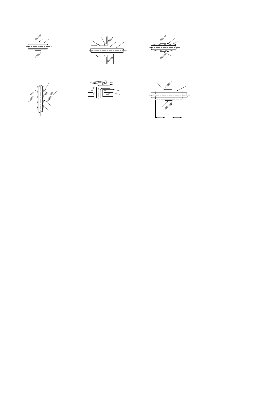
9-7-2. Insulation for the section of the pipe that goes through a wall
(1) Inner wall (concealed) (2) Outer wall (3) Outer wall (exposed)
ⒶⒷ
Ⓓ
Ⓒ
Ⓐ
Ⓑ
(4) Floor (waterproof) (5) Rooftop pipe shaft (6) Protecting the penetrating parts in a fire limit zone
or through a parting wall
Ⓓ
Ⓕ
Ⓓ
Ⓑ
Ⓒ
Ⓕ
Ⓗ
Ⓔ
Ⓑ
Ⓗ
Ⓘ
[mm (in)]
Ⓖ
Ⓑ
Ⓐ
1000
(39-3/8)
1000
(39-3/8)
Ⓐ Sleeve
Ⓑ Insulation material
Ⓒ Lagging
Ⓓ Caulking material
Ⓔ Band
Ⓕ Waterproof layer
Ⓖ Sleeve with a flange
Ⓗ Caulk with a nonflammable material such as mortar.
Ⓘ Nonflammable insulation material
・When caulking the gaps with mortar, cover the section of the pipe that goes through the wall with a metal sheet to
prevent the insulation material from sagging. For this section, use nonflammable insulation and covering materials.
(Vinyl tape should not be used.)
KD79S703H01
GB-28
Page 31

9-8. Evacuation of the system
Do not purge the air using refrigerant. Use a vacuum pump to evacuate the system.
- Residual gas in the refrigerant lines will cause bursting of the pipes or an explosion.
Use a vacuum pump with a check valve.
- If the vacuum pump oil flows back into the refrigerant lines, the refrigerant oil may deteriorate
and the compressor may malfunction.
<Evacuation procedures>
① Evacuate the system from both service ports, using a vacuum pump with the service valves closed.
② After the vacuum reaches 650 Pa, continue evacuation for at least one hour.
③ Stop the vacuum pump and leave it for an hour.
④ Verify that the vacuum has not increased by more than 130 Pa.
⑤ If the vacuum has increased by more than 130 Pa, water infiltration is suspected. Pressurize the system with dry
nitrogen gas up to 0.05 MPa. Repeat ① though ⑤ until the vacuum is increased by 130 Pa or below. If the
results persist, then perform the "Triple Evacuation" below.
<Triple Evacuation>
① Evacuate the system to 533 Pa from both service ports, using a vacuum pump.
② Pressurize the system with dry nitrogen gas up to 0 Pa from the discharge service port.
③ Evacuate the system to 200 Pa from the suction service port, using a vacuum pump.
④ Pressurize the system with dry nitrogen gas up to 0 Pa from the discharge service port.
⑤ Evacuate the system from both service ports, using a vacuum pump.
⑥ After the vacuum reaches 66.7 Pa, stop the vacuum pump and leave it for an hour. A vacuum of 66.7 Pa must
be maintained for at least one hour.
⑦ Verify that the vacuum has not increased for at least 30 minutes.
Ⓓ
Ⓝ
Ⓝ
Ⓐ
LO
ⒷⒸ
HI
Ⓞ
Ⓖ
Ⓗ
Ⓚ
Ⓔ
Ⓕ
Ⓘ
Ⓜ
Ⓙ
Ⓛ
Ⓐ Gauge manifold
Ⓑ Low pressure knob
Ⓒ High pressure knob
Ⓓ Service valve
Ⓔ Liquid piping
Ⓕ Gas piping
Ⓖ Service port
Ⓗ Three-way joint
Ⓘ Valve (vacuum pump)
Ⓙ Valve (for charging refrigerant)
Ⓚ Refrigerant tank
Ⓛ Scale
Ⓜ Vacuum pump
Ⓝ To indoor unit
Ⓞ Outdoor unit
・Use a scale that can measure down to 0.1 kg (0.1 oz).
・Recommended vacuum gauge: ROBINAIR 14830A Thermistor Vacuum Gauge or Micron Gauge
・Do not use a gauge manifold to measure the vacuum pressure.
・Use a vacuum pump capable of attaining a vacuum of 65 Pa (abs) within five minutes of operation.
GB
KD79S703H01
GB-29
Page 32

9-9. Additional refrigerant charge
Charge refrigerant in a liquid state.
- Charging refrigerant in the gaseous state will change the composition of the refrigerant and lead
to a performance drop.
Do not use a charging cylinder when charging refrigerant.
- The use of a charging cylinder may change the composition of the refrigerant and lead to a
performance drop.
The amount of refrigerant that is shown in the table below is factory-charged in the outdoor units. The amount
necessary for extended piping is not included and needs to be added on site.
Unit model Factory-charged amount [kg (oz)] Unit model Factory-charged amount [kg (oz)]
P200 6.5 (230) P400 11.5 (406)
P250 8.0 (283) P450 11.8 (417)
P300 11.5 (406) P500 11.8 (417)
P350 11.5 (406)
The amount of refrigerant that is shown in the table below is the maximum amount to be added on site.
Unit model Maximum amount to be added [kg (oz)] Unit model Maximum amount to be added [kg (oz)]
P200YKB-A1 22.3 (786) P400YSKB-A1 45.0 (1589)
P250YKB-A1 29.7 (1048) P450YSKB-A1 45.9 (1621)
P300YKB-A1 32.7 (1152) P500YSKB-A1 47.0 (1659)
P350YKB-A1 33.6 (1184) P550YSKB-A1 51.3 (1811)
P400YKB-A1 37.2 (1311) P600YSKB-A1 53.9 (1900)
P450YKB-A1 45.0 (1589) P650YSKB-A1 56.5 (1992)
P500YKB-A1 45.9 (1621) P700YSKB-A1 68.9 (2430)
P750YSKB-A1 68.9 (2430)
P800YSKB-A1 71.4 (2519)
P850YSKB-A1 73.2 (2583)
P900YSKB-A1 75.7 (2671)
P950YSKB-A1 96.9 (3421)
P1000YSKB-A1 99.9 (3527)
P1050YSKB-A1 102.9 (3634)
P1100YSKB-A1 106.0 (3740)
P1150YSKB-A1 109.0 (3847)
P1200YSKB-A1 112.0 (3954)
P1250YSKB-A1 112.0 (3954)
P1300YSKB-A1 112.0 (3954)
P1350YSKB-A1 112.0 (3954)
Both refrigerant overcharge and undercharge will cause problems. Charge the system with the proper amount of
refrigerant.
Record the added refrigerant amount on the label attached to the control box panel for future servicing.
KD79S703H01
GB-30
Page 33

9-9-1. Calculation of the amount of additional refrigerant
・The amount of refrigerant to be added depends on the size and the total length of the liquid piping.
・Calculate the amount of refrigerant to be charged according to the formula below.
・Round up the calculation result to the nearest 0.1 kg (0.1 oz).
(1) Units "m" and "kg"
<Formula>
・When the piping length from the outdoor unit to the farthest indoor unit is 30.5 m (100 ft) or shorter
Amount of
additional
charge (kg)
ø19.05 total length
=
× 0.29 (kg/m)
ø15.88 total length
+
× 0.2 (kg/m)
ø12.7 total length
+
× 0.12 (kg/m)
ø9.52 total length
+
× 0.06 (kg/m)
+
ø6.35 total length
× 0.024 (kg/m)
+
Outdoor unit
model
P200 0 80 or below 2.0
P250 0 81 to 160 2.5
P300 0 161 to 330 3.0
P350 0 331 to 390 3.5
P400 0 391 to 480 4.5
P450 0 481 to 630 5.0
P500 0 631 to 710 6.0
Amount (kg)
Total capacity of connected
indoor units
+
711 to 800 8.0
801 to 890 9.0
891 to 1070 10.0
1071 to 1250 12.0
1251 or above 14.0
Amount (kg)
・When the piping length from the outdoor unit to the farthest indoor unit is longer than 30.5 m (100 ft)
Amount of
additional
charge (kg)
ø19.05 total length
=
× 0.26 (kg/m)
Outdoor unit
model
P200 0 80 or below 2.0
P250 0 81 to 160 2.5
+
P300 0 161 to 330 3.0
P350 0 331 to 390 3.5
P400 0 391 to 480 4.5
P450 0 481 to 630 5.0
P500 0 631 to 710 6.0
ø15.88 total length
+
× 0.18 (kg/m)
Amount (kg)
ø12.7 total length
+
× 0.11 (kg/m)
Total capacity of connected
indoor units
+
711 to 800 8.0
801 to 890 9.0
891 to 1070 10.0
1071 to 1250 12.0
1251 or above 14.0
ø9.52 total length
+
× 0.054 (kg/m)
Amount (kg)
ø6.35 total length
+
× 0.021 (kg/m)
GB
<Example>
Outdoor unit model: P300
Total capacity of connected indoor units: 361
* Refer to the pipe connection examples in section 9-4 for the pipes marked with the letters below.
A: ø12.7; 40 m
B: ø9.52; 10 m
C: ø9.52; 15 m
D: ø9.52; 10 m
a: ø9.52; 10 m
b: ø9.52; 5 m
c: ø6.35; 10 m
d: ø6.35; 10 m
e: ø9.52; 10 m
KD79S703H01
GB-31
Page 34

The total length of each liquid piping is as follows:
ø12.7 total length: 40 (A)
ø9.52 total length: 10 (B) + 15 (C) + 10 (D) + 10 (a) + 5 (b) + 10 (e) = 60
ø6.35 total length: 10 (c) + 10 (d) = 20
Therefore, when the piping length from the outdoor unit to the farthest indoor unit is longer than 30.5 m (100 ft),
Amount of additional charge=(40 × 0.11) + (60 × 0.054) + (20 × 0.021) + 0 + 3.5
= 11.6 kg (Fractions are rounded up.)
(2) Units "ft" and "oz"
<Formula>
・When the piping length from the outdoor unit to the farthest indoor unit is 30.5 m (100 ft) or shorter
Amount of
additional
charge (oz)
ø3/4 total length
=
× 3.1 (oz/ft)
ø5/8 total length
+
× 2.15 (oz/ft)
ø1/2 total length
+
× 1.29 (oz/ft)
ø3/8 total length
+
× 0.65 (oz/ft)
ø1/4 total length
+
× 0.26 (oz/ft)
+
Outdoor unit
model
P200 0 80 or below 71
P250 0 81 to 160 89
P300 0 161 to 330 106
P350 0 331 to 390 124
P400 0 391 to 480 160
P450 0 481 to 630 177
P500 0 631 to 710 212
Amount (oz)
Total capacity of connected
indoor units
+
711 to 800 283
801 to 890 318
891 to 1070 353
1071 to 1250 424
1251 or above 494
Amount (oz)
・When the piping length from the outdoor unit to the farthest indoor unit is longer than 30.5 m (100 ft)
Amount of
additional
charge (oz)
ø3/4 total length
=
× 2.80 (oz/ft)
Outdoor unit
model
P200 0 80 or below 71
P250 0 81 to 160 89
+
P300 0 161 to 330 106
P350 0 331 to 390 124
P400 0 391 to 480 160
P450 0 481 to 630 177
P500 0 631 to 710 212
ø5/8 total length
+
× 1.94 (oz/ft)
Amount (oz)
ø1/2 total length
+
× 1.19 (oz/ft)
Total capacity of connected
indoor units
+
711 to 800 283
801 to 890 318
891 to 1070 353
1071 to 1250 424
1251 or above 494
ø3/8 total length
+
× 0.58 (oz/ft)
Amount (oz)
ø1/4 total length
+
× 0.23 (oz/ft)
<Example>
Outdoor unit model: P300
Total capacity of connected indoor units: 361
* Refer to the pipe connection examples in section 9-4 for the pipes marked with the letters below.
A: ø1/2; 131 ft
B: ø3/8; 32 ft
C: ø3/8; 49 ft
D: ø3/8; 32 ft
a: ø3/8; 32 ft
b: ø3/8; 16 ft
c: ø1/4; 32 ft
d: ø1/4; 32 ft
e: ø3/8; 32 ft
KD79S703H01
GB-32
Page 35

The total length of each liquid piping is as follows:
ø1/2 total length: 131 (A)
ø3/8 total length: 32 (B) + 49 (C) + 32 (D) + 32 (a) + 16 (b) + 32 (e) = 193
ø1/4 total length: 32 (c) + 32 (d) = 64
Therefore, when the piping length from the outdoor unit to the farthest indoor unit is longer than 30.5 m (100 ft),
Amount of additional charge = (131 × 1.19) + (193 × 0.58) + (64 × 0.23) + 0 + 124
= 406.6 oz (Fractions are rounded up.)
9-9-2. Charging additional refrigerant
Charge the calculated amount of refrigerant in the liquid state to the unit through the service port after the completion
of piping work. Upon completion of all work, securely tighten all service port caps and shaft caps to prevent refrigerant
leakage.
・Do not vent the refrigerant into the atmosphere.
・Refer to the table below for the appropriate tightening torque.
Pipe size [mm (in)] Shaft cap (N·m) Shaft (N·m) Size of hexagonal wrench [mm (in)] Service port cap (N·m)
ø9.52 (ø3/8) 22 6 4 (3/16)
ø12.7 (ø1/2) 27 10 4 (3/16)
ø15.88 (ø5/8) 32 12 4 (3/16)
ø19.05 (ø3/4) 50 30 8 (3/8)
ø25.4 (ø1) 50 30 8 (3/8)
ø28.58 (ø1-1/8) 22 - - 16
12
GB
・If the refrigerant tank does not have a siphon pipe, charge the liquid refrigerant with the tank upside-down as shown
in the figure below.
Ⓐ
Ⓐ Siphon pipe
・After evacuation and refrigerant charging, ensure that the service valves are fully open. Do not operate the unit
with the service valves closed.
KD79S703H01
GB-33
Page 36

10. Electrical work
Electrical work must be performed by qualified personnel in accordance with local
regulations and the instructions provided in this manual. Only use the specified cables and
dedicated circuits.
- Inadequate power source capacity or improper electrical work will result in electric shock,
malfunction, or fire.
Proper grounding must be provided by qualified personnel.
- Improper grounding may result in electric shock, fire, explosion, or malfunction due to electrical
noise. Do not connect the ground wire to gas or water pipes, lightning rods, or telephone ground
wires.
10-1. Before electrical work
・When performing electrical work, refer to the indoor unit or controller installation manuals as well.
・Bear in mind ambient conditions (ambient temperature, direct sunlight, rain water, etc.) when proceeding with the
wiring and connections.
・When opening or closing the front panel of the control box, do not let it come into contact with any of the internal
components.
・Specific wiring requirements should adhere to the wiring regulations of the region.
・Include some slack in the wiring for the control box on the indoor and outdoor units, because these boxes are
sometimes removed at the time of service work.
10-2. Power cables and device capacity
Include some slack in the power cables.
- Failure to do so may break or overheat the cables, resulting in smoke or fire.
Install an inverter circuit breaker on the power supply of each unit.
- Failure to do so may result in electric shock or fire.
Only use properly rated breakers (an earth leakage breaker, local switch <a switch + fuse
that meets local electrical codes>, or overcurrent breaker).
- Failure to do so may result in electric shock, malfunction, smoke, or fire.
Only use standard power cables of sufficient capacity.
- Failure to do so may result in current leakage, overheating, smoke, or fire.
Tighten all terminal screws to the specified torque.
- Loose screws and contact failure may result in smoke or fire.
If a large electric current flows due to a malfunction or faulty wiring, earth-leakage breakers
on the unit side and on the upstream side of the power supply system could both operate.
Depending on the importance of the system, separate the power supply system or take
protective coordination of breakers.
KD79S703H01
GB-34
Page 37

・Wiring example
Ⓐ Earth leakage breaker
Ⓑ Local switch (Overcurrent breaker and earth
leakage breaker)
Ⓒ Outdoor unit
Ⓓ Pull box
Ⓔ Indoor unit
Ⓕ Earth
3N~380–415 V
L1, L2, L3, N
~220–240 V
L, N
ⒷⒶ
Ⓒ
Ⓕ
ⒷⒶ
ⒺⒺⒹⒺⒺ
Ⓕ Ⓕ Ⓕ Ⓕ
・Be sure to use the appropriate type of overcurrent breaker. Note that generated overcurrent may include some
amount of direct current.
・Select the type of breaker for an inverter circuit as an earth leakage breaker. (Mitsubishi Electric NV-S series or its
equivalent)
・The earth leakage breaker should be used in combination with a local switch.
・Use a local switch with at least 3 mm (1/8 in) contact separation in each pole.
・Do not connect the power cables L1, L2, and L3 to N. Ensure the correct phase sequence.
・If the power cable is damaged, it must be replaced by the manufacturer, its service agent or similarly qualified
persons in order to avoid a hazard.
・Use dedicated power cables for the outdoor unit and indoor unit. Ensure OC and OS are wired individually.
・Power cable size, device capacity, and system impedance
(If local regulations do not specify the minimum power cable size or device capacity, follow the values in the table
below.)
Minimum size [mm2 (AWG)]
Power
cable
P200 4.0 (12) – 4.0 (12)
P250 4.0 (12) – 4.0 (12)
P300 4.0 (12) – 4.0 (12)
Outdoor
unit
Total
operating
current of
the indoor
units
*1 : Use the larger value of F1 or F2 as the value of F0.
F1 = Total of each indoor unit's maximum current × 1.2
F2 = {V1 × (Quantity of Type 1)/C} + {V1 × (Quantity of Type 2)/C} + {V1 × (Quantity of Type 3)/C} + {V1 × (Quantity of Type 4)/C}
*2 : Current sensitivity is calculated using the following formula.
G1 = (V2 × Quantity of Type 1) + (V2 × Quantity of Type 2) + (V2 × Quantity of Type 3) + (V2 × Quantity of Type 4) +
P350 6.0 (10) – 6.0 (10)
P400 10.0 (8) – 10.0 (8)
P450 10.0 (8) – 10.0 (8)
P500 10.0 (8) – 10.0 (8)
F0 ≤ 16 A *
F0 ≤ 25 A *
F0 ≤ 32 A *
(V3 × Power cable length (km))
1
1.5 (16) 1.5 (16) 1.5 (16)
1
2.5 (14) 2.5 (14) 2.5 (14)
1
4.0 (12) 4.0 (12) 4.0 (12)
Power cable
after branching
point
Earth
Earth leakage breaker
wire
30 A 100 mA 0.1 sec.
or less
30 A 100 mA 0.1 sec.
or less
30 A 100 mA 0.1 sec.
or less
40 A 100 mA 0.1 sec.
or less
60 A 100 mA 0.1 sec.
or less
60 A 100 mA 0.1 sec.
or less
60 A 100 mA 0.1 sec.
or less
20 A current sensitivity
2
*
30 A current sensitivity
2
*
40 A current sensitivity
2
*
Local switch (A)
Capacity Fuse
25 25 30 (IEC 61000-3-3)
32 32 30 (IEC 61000-3-3)
32 32 30 (IEC 61000-3-3)
40 40 40 0.25 Ω
63 63 60 0.22 Ω
63 63 60 0.19 Ω
63 63 60 0.16 Ω
16 16 20 (IEC 61000-3-3)
25 25 30 (IEC 61000-3-3)
32 32 40 (IEC 61000-3-3)
Overcurrent
breaker
(NFB) (A)
Maximum
allowable system
impedance
GB
KD79S703H01
GB-35
Page 38

Indoor unit V1 V2
Type 1
Type 2 PEFY-VMA 38 1.6
Type 3 PEFY-VMHS 13.8 4.8
Type 4 Indoor unit other than the above 0 0
"C" is multiples of the tripping current at 0.01 s.
Obtain the value of "C" from the tripping characteristic of the breaker that is used on site.
<Example of "F2" calculation>
Conditions: PEFY-VMS × 4 units, PEFY-VMA × 1 unit, "C" = 8 (See the sample chart.)
F2 = 18.6 × 4/8 + 38 × 1/8
30 mA or less 30 mA 0.1 sec or less
100 mA or less 100 mA 0.1 sec or less
PLFY-VBM, PMFY-VBM, PEFY-VMS, PCFY-VKM,
PKFY-VHM, PKFY-VKM, PFFY-VKM, PFFY-VLRMM
= 14.05
→ Use a 16 A type breaker. (Tripping current = 8 × 16 A at 0.01 s)
Power cable size [mm2 (AWG)] V3
1.5 (16) 48
2.5 (14) 56
4.0 (12) 66
G1 Current sensitivity
18.6 2.4
Sample chart
6000
600
60
10
Tripping Time [s]
1
0.1
0.01
1
Multiples of rated tripping current
SAMPLE
C
20
1086432
・The wire size is the minimum value for metal conduit wiring. If the voltage drops, use a wire that is one size
thicker in diameter. Make sure the power-supply voltage does not drop more than 10%. Make sure that the
voltage imbalance between the phases is 2% or less.
・Power supply cords of parts of appliances for outdoor use shall not be lighter than polychloroprene sheathed
flexible cord (design 60245 IEC57). For example, use wiring such as YZW.
・This unit is intended for the connection to a power supply system with a maximum permissible system
impedance shown in the above table at the interface point (power service box) of the user’s supply.
・The user must ensure that this unit is connected only to a power supply system which fulfils the requirement
above.
If necessary, the user can ask the public power supply company for the system impedance at the interface point.
・This unit complies with IEC 61000-3-12 provided that the short-circuit power Ssc is greater than or equal to
Ssc*1 at the interface point between the user’s supply and the public system. It is the responsibility of the
installer or user of the equipment to ensure, by consultation with the distribution network operator if necessary,
that the equipment is connected only to a supply with a short-circuit power Ssc greater than or equal to Ssc*1.
*1 Ssc
Model Ssc (MVA)
P200 1.39
P250 1.54
P300 1.91
P350 2.43
P400 2.82
P450 3.26
P500 3.83
KD79S703H01
GB-36
Page 39

10-3. Control cable specifications
・Transmission cable
Type 2-core shielded cable CVVS, CPEVS, or MVVS
Size 1.25 mm
Length Max. 200 m (656 ft)
The maximum allowable length of transmission cables via outdoor units (both centralized control transmission cables
Remarks
* Do not use a single multiple-core cable to connect indoor units that belong to different refrigerant systems. The use of a multiple-core cable
may result in signal transmission errors and malfunctions.
* Ensure shield continuity when extending the transmission cable.
and indoor-outdoor transmission cables) is 500 m (1640 ft).
The maximum allowable length of transmission cables from the power supply unit to each outdoor unit or to the system
controller is 200 m (656 ft).
2
(AWG 16), or ø1.2 mm or above
・Remote controller cable
ME remote controller cable MA remote controller cable
Type 2-core sheathed cable (unshielded) CVV
Size 0.3–1.25 mm
Max. 10 m (32 ft)
Length
* If the length exceeds 10 m (32 ft), use a 1.25 mm
(AWG 16) shielded cable.
2
(AWG 22–16) (0.75–1.25 mm2 (AWG 18–16) if a simple remote controller is connected)
2
Max. 200 m (656 ft)
10-4. System configuration
・Unit code and the maximum number of connectable units
Unit type Code Number of connectable units
Outdoor unit
Indoor unit IC 1 to 26 units per OC
Remote controller RC 0 to 2 units per group
Transmission booster unit RP 0 to 1 unit per OC
* A transmission booster may be required depending on the number of connected indoor units.
* The outdoor units in the same refrigerant circuit are automatically designated as OC, OS1, and OS2. The outdoor units are designated as OC,
OS1, and OS2 in the order of capacity from large to small (if two or more units have the same capacity, in the order of address from small to
large).
Main unit OC –
Sub unit OS1, OS2 –
GB
KD79S703H01
GB-37
Page 40

・System configuration example
* The numbers in the parentheses in the figures below indicate address numbers.
(1) When ME remote controllers are connected
* Move the power jumper from
CN41 to CN40. *
* SW5-1: ON *
1
2
Ⓐ
Group 1 Group 3 Group 5
Ⓐ Shielded cable
Ⓑ Sub remote controller
Ⓒ System controller
* Leave the power jumper
connected to CN41.
* SW5-1: ON *
2
Ⓒ
Ⓑ
*1 When a power supply unit is not connected to the centralized control transmission cable, move the power jumper from CN41 to CN40 on
only one of the outdoor units.
*2 If a system controller is used, set SW5-1 on all of the outdoor units to ON.
Maximum allowable length of control cables
Transmission cables via outdoor units L1 + L2 + L3 + L4, L1 + L2 + L3 + L5, L1 + L2 + L6 ≤ 500 m (1640 ft)
Transmission cables L
Remote controller cables
1, L3 + L4, L3 + L5, L6, L2 + L6 ≤ 200 m (656 ft)
1, ℓ2, ℓ3, ℓ4 ≤ 10 m (32 ft)
ℓ
* If the length exceeds 10 m (32 ft), the length that exceeds 10 m (32 ft) needs
to be included in the maximum allowable length of transmission cables
above.
KD79S703H01
GB-38
Page 41
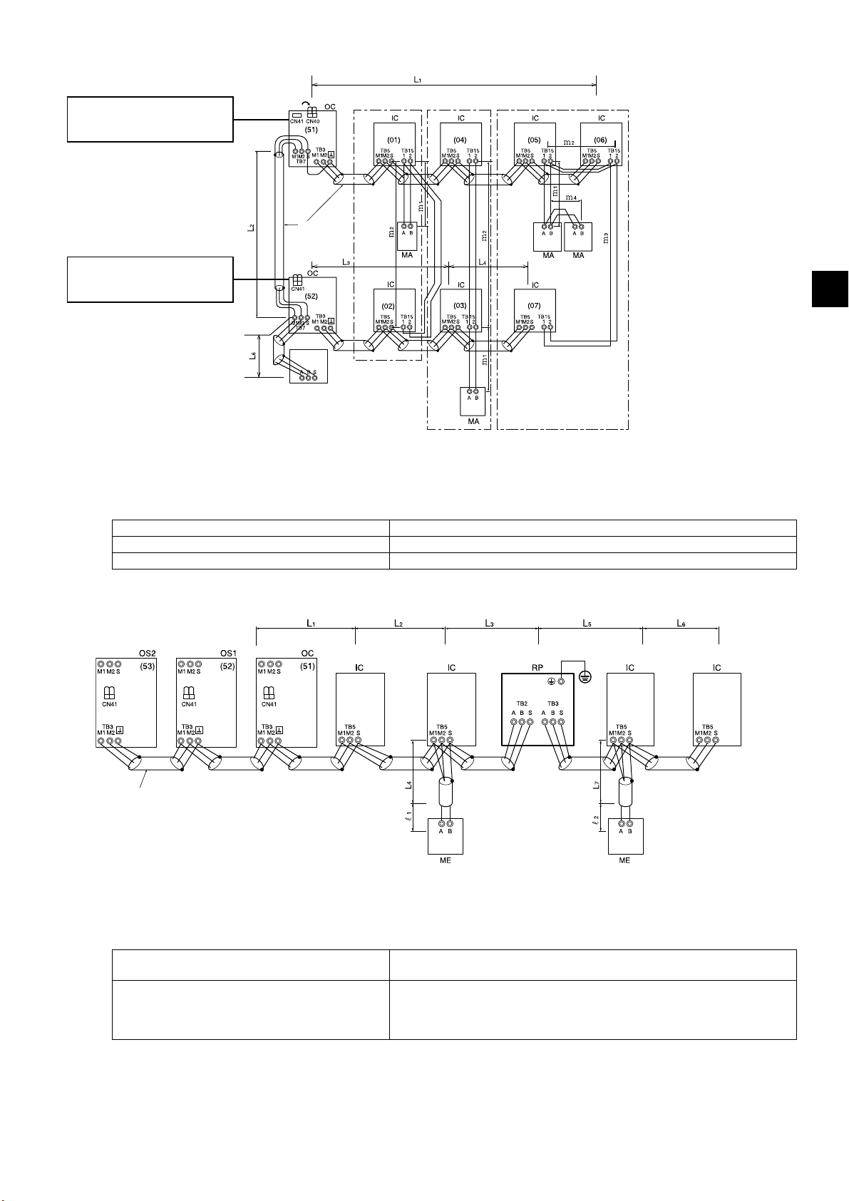
(2) When MA remote controllers are connected
* Move the power jumper from
CN41 to CN40. *
* SW5-1: ON *
1
2
Ⓐ
Group 1 Group 3 Group 5
Ⓐ Shielded cable
Ⓑ Sub remote controller
Ⓒ System controller
* Leave the power jumper
connected to CN41.
* SW5-1: ON *
2
Ⓒ
Ⓑ
*1 When a power supply unit is not connected to the centralized control transmission cable, move the power jumper from CN41 to CN40 on
only one of the outdoor units.
*2 If a system controller is used, set SW5-1 on all of the outdoor units to ON.
*3 When a PAR-31MAA is connected to a group, no other MA remote controllers can be connected to the same group.
Maximum allowable length of control cables
Transmission cables via outdoor units L1 + L2 + L3 + L4, L1 + L2 + L6 ≤ 500 m (1640 ft)
Transmission cables L
Remote controller cables m
1, L3 + L4, L6, L2 + L6 ≤ 200 m (656 ft)
1 + m2, m1 + m2 + m3 + m4 ≤ 200 m (656 ft)
(3) When a transmission booster unit is connected
Earth
TB7 TB7 TB7
GB
Ⓐ
Ⓐ Shielded cable
*1 Daisy-chain terminals (TB3) on outdoor units together in the same refrigerant system.
*2 Leave the power jumper connected to CN41.
Maximum allowable length of control cables
Transmission cables
Remote controller cables
KD79S703H01
L1 + L2 + L3 + L5 + L6, L1 + L2 + L3 + L5 + L7, L1 + L2 + L4,
L6 + L5 + L3 + L4, L4 + L3 + L5 + L7 ≤ 200 m (656 ft)
ℓ
1, ℓ2 ≤ 10 m (32 ft)
* If the length exceeds 10 m (32 ft), the length that exceeds 10 m (32 ft) needs
to be included in the maximum allowable length of transmission cables
above.
GB-39
Page 42

10-5. Wiring connections in the control box
Connections must be made securely and without tension on the terminals.
- Improperly connected cables may break, overheat, or cause smoke or fire.
10-5-1. Threading power cable through the knockout hole
・Punch out the knockout holes at the bottom of the front panel with a hammer.
Ⓐ
Ⓐ Cable strap
Ⓑ
Ⓒ
Ⓑ Power cable
Ⓒ Transmission cable
・If there are any gaps around the power cable, please be sure to fill these in with a suitable material.
・When putting the power cable through the knockout hole without using a conduit tube, deburr the hole and protect
the power cable with protective tape.
・Use a conduit tube to narrow down the opening if there is a possibility of small animals entering the unit.
・When taking the conduit tube out from the bottom part of the unit, caulk around the tube opening to prevent water
infiltration.
KD79S703H01
GB-40
Page 43

10-5-2. Fixing the cables in place
Power supply terminal block
Cable strap
Rubber bushing
M-NET
board
Transmission
terminal block
Cable strap
Tie band
(Supplied)
Power cable
(not supplied)
Transmission cable
(not supplied)
Unit wiring (sensor wiring)
Tie band
(Supplied)
Rubber bushing
① Thread the power cable through the rubber bushing on the left side. (See *1 and *2 below.)
② Thread the unit wiring (sensor wiring) and the transmission cable through the rubber bushing on the right side.
(See *1 and *2 below.)
③ Hold the power cable and the transmission cable in place respectively with the cable straps.
④ Secure each rubber bushing with the supplied tie band. (See *3 below.)
*1 Make sure the cables are not coming out of the rubber bushing cut.
Top view
Cut
Rubber bushing
(oval part)
Rubber bushing
(oval part)
Cables are coming out of the rubber bushing.
Wiring
Cross-sectional view
Top view
Wiring
Rubber bushing
Wiring
*2 When threading the wiring through the rubber bushing, make sure the rubber bushing will not come off the sheet metal on the control box
guard.
GB
Sheet metal on
the guard
Rubber bushing
Sheet metal on
the guard
Rubber bushing
*3 When tying the supplied tie band around the rubber bushing, make sure to leave no gap between the ends.
Tie band
Overlapped
rubber bushing
Approx. 20 mm (13/16 in)
Cut on the
rubber bushing
<Back of the rubber bushing>
There is a gap in
the rubber
bushing.
Cut on the
rubber
bushing
<<Important>>
When putting the tie band on the rubber bushing, make sure the
ends of the rubber bushing overlap each other as shown in the figure
at left.
* If there is a gap, water from snow or rain may enter, resulting in
equipment damage.
KD79S703H01
GB-41
Page 44

10-5-3. Connecting the cables
Ⓐ
Ⓑ
L1 L2 L3 N
Ⓒ
ⒹⒺ
Ⓐ Control box
Ⓑ Power supply terminal block (TB1)
Ⓒ Transmission cable
Ⓓ Terminal block for indoor-outdoor transmission cable
(TB3)
Ⓔ Terminal block for centralized control transmission
cable (TB7)
Ⓒ
ⒶⒷ
Ⓓ
Ⓑ
Ⓐ
Ⓔ
Ⓒ
Ⓐ Power cables, transmission cables
Ⓑ Daisy-chain (transmission cables only)
Ⓒ Terminal blocks (TB1, TB3, TB7)
Ⓓ Make an alignment mark.
Ⓔ Install the ring terminals back to back.
Ⓐ Terminal block with loose screws
Ⓑ Properly installed terminal block
Ⓒ Spring washers must be parallel to the terminal block.
・Connect the cables respectively to the power supply terminal block and the transmission terminal block.
Erroneous connection does not allow the system to operate.
・Never connect the power cable to the transmission terminal block. If connected, electrical parts will be damaged.
・When connecting cables to TB7, check that the voltage is 20 VDC or below.
・Transmission cables should be (5 cm (2 in) or more) apart from the power cable so that it is not influenced by
electric noise from the power cable. (Do not put the transmission cables and the power cable in the same
conduit.)
・Follow the tightening torque for each screw type as shown below. Be careful not to use excessive torque as this
could damage the screw.
Terminal block (TB1 (M6 screw)): 2.5–2.9 [N·m]
Terminal block (TB3, TB7 (M3.5 screw)): 0.82–1.0 [N·m]
・When tightening the screws, do not push the driver strongly to avoid damaging the screw.
・Make an alignment mark with a permanent marker across the screw head, washer, and terminal after tightening
the screws.
① Connect the indoor-outdoor transmission cable to TB3.
If multiple outdoor units are connected to the same refrigerant system, daisy-chain TB3 (M1, M2, earth) on the
outdoor units. The indoor-outdoor transmission cable to the indoor unit should be connected to TB3 (M1, M2,
earth) of only one of the outdoor units. Connect the shield to the earth terminal.
② Connect the centralized control transmission cables (between the centralized control system and the outdoor
units of different refrigerant systems) to TB7.
If multiple outdoor units are connected to the same refrigerant system, daisy-chain TB7 (M1, M2, S) on all
outdoor units.*1 Connect the shield to the S terminal.
*1 If TB7 on the outdoor units in the same refrigerant system are not daisy-chained, connect the centralized control transmission cable to
TB7 on the OC. If the OC is out of order, or if centralized control is being conducted during a power supply shut-off, daisy-chain TB7 on
the OC, OS1 and OS2. (In the case that the outdoor unit whose power jumper CN41 on the control board has been replaced with CN40 is
out of order or the power is shut-off, centralized control will not be conducted even when TB7 is daisy-chained.)
③ When a power supply unit is not connected to the centralized control transmission cable, move the power
jumper from CN41 to CN40 on only one of the outdoor units.
④ On the outdoor unit whose power jumper was moved from CN41 to CN40, short circuit the S terminal and the
earth terminal.
⑤ Connect terminals M1 and M2 of the transmission terminal block on the indoor unit that has the lowest address
in the group to the terminal block on the remote controller.
⑥ When a system controller is connected, set SW5-1 on all outdoor units to ON.
⑦ Fix the cables securely in place with the cable strap below the terminal block.
KD79S703H01
GB-42
Page 45

10-6. Address setting
・Set the address setting switch as follows.
Address setting method Address
Indoor unit (Main, Sub)
Outdoor unit (OC, OS1, OS2)
ME remote controller
MA remote controller Address setting is not required. (The Main/Sub setting is required.) –
* The outdoor units in the same refrigerant circuit are automatically designated as OC, OS1, and OS2. The outdoor units are designated as OC,
OS1, and OS2 in the order of capacity from large to small (if two or more units have the same capacity, in the order of address from small to
large).
* Make indoor unit group settings from remote controllers after turning on the power to all units.
Main Assign an address that equals the address of the main indoor unit in the group plus 100. 101 to 150
Sub Assign an address that equals the address of the main indoor unit in the group plus 150. 151 to 200
Assign the lowest address to the main indoor unit in the group, and assign sequential
addresses to the rest of the indoor units in the same group.
Assign sequential addresses to the outdoor units in the same refrigerant system.
* To set the address to 100, the address setting switch must be set to 50.
01 to 50
51 to 100
GB
KD79S703H01
GB-43
Page 46

11. Test run
11-1. Before a test run
After the wiring work has been completed, measure the insulation resistance, and make
sure that it reads at least 1 MΩ.
- Failure to do so may result in electric leakage, malfunction, or fire.
Turn on the power at least 12 hours before starting operation. Keep the power turned on
throughout the operating season.
- Insufficient energizing will result in malfunction.
・Before performing a test run, turn off the power to the outdoor unit, and disconnect the power cable from the power
supply terminal block to measure the insulation resistance.
・Measure the insulation resistance between the power supply terminal block and the earth with a 500 V ohmmeter,
and make sure it is at least 1 MΩ.
・If the insulation resistance is 1 MΩ or above, connect the power cable to the power supply terminal, and turn on the
power at least 12 hours before starting operation. If the insulation resistance is below 1 MΩ, do not operate the unit,
and check the compressor for a earth fault.
・While the unit is turned on, the compressor will remain energized even when it is stopped.
・The insulation resistance between the power supply terminal block and the earth may drop to near 1 MΩ
immediately after installation or when the main power to the unit has been turned off for a long time because of the
stagnation of refrigerant in the compressor.
・By turning on the main power and energizing the unit for 12 hours or longer, the refrigerant in the compressor will
evaporate and the insulation resistance will rise.
・Do not apply an ohmmeter voltage to the terminal block for transmission cables. Doing so will damage the control
board.
・Do not measure the insulation resistance of the transmission terminal block of the unit remote controller.
・Check for refrigerant leakage and for loose power cables and transmission cables.
・Check that the liquid and gas side service valves are fully open. Tighten the valve caps.
・Check the phase order of the power supply and the interphase voltage. If the voltage is out of the ±10% range, or if
the voltage imbalance is more than 2%, discuss the countermeasure with the customer.
・When a transmission booster unit is connected, turn on the transmission booster unit before turning on the outdoor
unit. If the outdoor unit is turned on first, the refrigerant circuit connection information will not be properly verified. If
the outdoor unit is turned on first, turn on the transmission booster unit and then power reset the outdoor unit.
・When a power supply unit is connected to the centralized control transmission cable, or when power is supplied
from a system controller with a power-supply function, perform a test run with the power supply unit being
energized. Leave the power jumper connected to CN41.
・When power is turned on or after power recovery, performance may degrade for approximately 30 minutes.
KD79S703H01
GB-44
Page 47

11-2. Function setting
Make function settings by setting the dipswitches SW4, SW6, and SWP1 on the main board.
Write down the switch settings on the electrical wiring diagram label on the control box front panel for future reference
when the control box needs to be replaced.
・Take the following steps to make snow sensor settings. (Snow sensor control will not function when the outdoor
temperature sensor (TH7) reading is 6ºC (43ºF) or above.)
① Set the 10th bit of SW6 to ON.
② Set SW4 as shown in the table below to select the setting item No.933 or 934. (The setting item No. will be
displayed on LED1.)
③ Press SWP1 for two seconds or longer to change the settings. (The settings can be checked on LED3.)
Setting item
No.
Snow sensor
setting
*1 Make the SW4 setting after the unit is energized.
*2 This will blink while the system is starting up.
933 1010010111 No. 934 ineffective No. 934 effective
934 0110010111 Continuous fan operation Intermittent fan operation
12345678910 Unlit Lit
SW4 0: OFF, 1: ON *
1
・Make various function settings by setting SW6, referring to the table below.
Setting (LED3 display) *
2
GB
Setting content
SW6-1 – – – –
SW6-2 – – – –
SW6-3 – – – –
SW6-4 Static pressure setting Standard static pressure High static pressure Before being energized
SW6-5 High static pressure setting 60 Pa 30 Pa Before being energized
SW6-6 – – – –
SW6-7 Low-noise mode selection Performance priority Low-noise priority Any time after being energized
SW6-8 Selection of Low-noise or Demand Low-noise (Night) Demand Before being energized
SW6-9 – – – –
SW6-10
* Do not change the factory settings of SW5-3 through SW5-8.
* Unless otherwise specified, leave the switch to OFF where indicated by "–," which may be set to OFF for a reason.
Selection of Diagnostic display or
Function detail setting
OFF ON
Diagnostic display Function detail setting Any time after being energized
Setting
Switch setting timing
11-3. Operation characteristics in relation to the refrigerant charge
It is important to have a clear understanding of the characteristics of refrigerant and the operation characteristics of air
conditioners before attempting to adjust the refrigerant charge in a given system.
・During cooling operation, the amount of refrigerant in the accumulator is the smallest when all indoor units are in
operation.
・During heating operation, the amount of refrigerant in the accumulator is the largest when all indoor units are in
operation.
・Refrigerant undercharge creates a tendency for the discharge temperature to rise.
・Changing the amount of refrigerant in the system while there is refrigerant in the accumulator has little effect on the
discharge temperature.
・The higher the high pressure level, the more likely it is for the discharge temperature to rise.
・The lower the low pressure level, the more likely it is for the discharge temperature to rise.
・When the amount of refrigerant in the system is adequate, the compressor shell temperature is 10 to 60ºC (50 to
140ºF) higher than the low-pressure saturation temperature. If the temperature difference between the compressor
shell temperature and low-pressure saturation temperature is 5ºC (41ºF) or less, refrigerant overcharge is
suspected.
KD79S703H01
GB-45
Page 48

11-4. Operation check
The following symptoms are normal and do not indicate a problem.
Events Display on
remote
controller
A specific indoor unit is not performing the
cooling or heating operation.
The auto vane automatically switches air
flow direction.
The fan speed automatically changes
during heating operation.
The fan stops during heating operation. "Defrost" The fan remains stopped during the defrost cycle.
The fan keeps running after the unit has
stopped.
At the beginning of heating operation, the
fan cannot be manually set.
When the main power is turned on, the
display as shown right appears on the
remote controller for about five minutes.
The drain pump keeps running after the
unit has stopped.
The indoor unit emits noise when
switching from heating to cooling and vice
versa.
Immediately after startup, the indoor unit
emits the sound of refrigerant flowing.
Warm air comes from an indoor unit that
is not performing the heating operation.
"Cool" or "Heat"
blinks.
Normal display The auto vane may switch over to horizontal air flow operation from vertical air flow
Normal display The fan operates at Very Low speed when the thermostat is turned off, and
No display After the unit has stopped during heating operation, the fan operates for one
"Stand By" The fan operates at Very Low speed for five minutes after heating operation starts
"HO" or
"PLEASE WAIT"
blinks.
No display The drain pump remains in operation for three minutes after the unit in cooling
Normal display This is a normal sound of the refrigerant circuit operating properly.
Normal display Unstable flow of the refrigerant produces a sound. This is temporary and does not
Normal display The LEV is slightly open for preventing any refrigerant, inside of the indoor unit that
Cause
Other indoor units in the same refrigerant system are already operated in a
different mode.
operation in cooling mode if the vertical air flow operation has been running for one
hour. At defrost in heating mode or immediately after heating start-up/shutdown,
the auto vane automatically switches to horizontal air flow for a short time.
automatically changes over to the preset speed according to the timer setting or
refrigerant temperature when the thermostat is turned on.
minute to exhaust heat.
or until the refrigerant temperature reaches 35°C (95°F), then the fan operates at
Low speed for two minutes, and finally the fan operates at the preset speed.
The system is starting up. Wait until "HO" or "PLEASE WAIT" stops blinking and
goes off then try again.
mode has stopped.
The drain pump goes into operation when drain water is detected, even when the
unit is stopped.
imply a problem.
is not performing the heating operation, from being liquefied. This does not imply a
problem.
KD79S703H01
GB-46
Page 49

12. Inspection and maintenance
Only qualified personnel must relocate or repair the unit. Do not attempt to disassemble or
alter the unit.
- Failure to do so will result in refrigerant leakage, water leakage, serious injury, electric shock, or
fire.
・While the unit is turned on, the compressor will remain energized even when it is stopped. Before inspecting the
inside of the control box, turn off the power, keep the unit off for at least 10 minutes, and confirm that the capacitor
voltage (inverter main circuit) has dropped to 20 VDC or less. (It takes about 10 minutes to discharge electricity
after the power supply is turned off.)
・Control boxes house high-voltage and high-temperature electrical parts. They may still remain energized or hot
after the power is turned off.
・Perform the service after disconnecting the fan board connector (CNINV) and the inverter board connector (CN1).
(To plug or unplug connectors, check that the outdoor unit fan is not rotating and that the voltage of capacitor in the
main circuit is 20 VDC or below. The capacitor may collect a charge and cause an electric shock when the outdoor
unit fan rotates in windy conditions. Refer to the wiring nameplate for details.)
Reconnect the connector (CNINV) back to the fan board and reconnect the connector (CN1) back to the inverter
board after servicing.
・Unit components may be damaged after long use of the unit, resulting in a performance drop or the unit becoming a
safety hazard. To use the unit safely and maximize its life, it is recommended that a maintenance contract with a
dealer or qualified personnel be signed. If the contract is signed, service technicians will periodically inspect the unit
to identify any damage at an early stage, and take appropriate measures.
GB
KD79S703H01
GB-47
Page 50

13. Rating plate information
Model P200YKB-A1 P250YKB-A1 P300YKB-A1 P350YKB-A1 P400YKB-A1 P450YKB-A1 P500YKB-A1
Unit combination – – – – – – –
Refrigerant (R410A)
Allowable pressure
(Ps)
Net weight 190 kg 199 kg 251 kg 251 kg 251 kg 304 kg 304 kg
Model P400YSKB-A1 P450YSKB-A1 P500YSKB-A1 P550YSKB-A1
Unit combination P200 P200 P250 P200 P250 P250 P300 P250
Refrigerant (R410A)
Allowable pressure
(Ps)
Net weight 190 kg 190 kg 199 kg 190 kg 199 kg 199 kg 251 kg 199 kg
Model P600YSKB-A1 P650YSKB-A1 P700YSKB-A1 P750YSKB-A1
Unit combination P350 P250 P350 P300 P350 P350 P400 P350
Refrigerant (R410A)
Allowable pressure
(Ps)
Net weight 251 kg 199 kg 251 kg 251 kg 251 kg 251 kg 251 kg 251 kg
Model P800YSKB-A1 P850YSKB-A1 P900YSKB-A1
Unit combination P450 P350 P450 P400 P450 P450
Refrigerant (R410A)
Allowable pressure
(Ps)
Net weight 304 kg 251 kg 304 kg 251 kg 304 kg 304 kg
6.5 kg 8.0 kg 11.5 kg 11.5 kg 11.5 kg 11.8 kg 11.8 kg
HP: 4.15 MPa, LP: 2.21 MPa
6.5 kg 6.5 kg 8.0 kg 6.5 kg 8.0 kg 8.0 kg 11.5 kg 8.0 kg
HP: 4.15 MPa, LP: 2.21 MPa
11.5 kg 8.0 kg 11.5 kg 11.5 kg 11.5 kg 11.5 kg 11.5 kg 11.5 kg
HP: 4.15 MPa, LP: 2.21 MPa
11.8 kg 11.8 kg 11.8 kg 11.5 kg 11.8 kg 11.8 kg
HP: 4.15 MPa, LP: 2.21 MPa
Model P950YSKB-A1 P1000YSKB-A1
Unit combination P400 P300 P250 P400 P300 P300
Refrigerant (R410A)
Allowable pressure
(Ps)
Net weight 251 kg 251 kg 199 kg 251 kg 251 kg 251 kg
Model P1050YSKB-A1 P1100YSKB-A1
Unit combination P400 P350 P300 P400 P350 P350
Refrigerant (R410A)
Allowable pressure
(Ps)
Net weight 251 kg 251 kg 251 kg 251 kg 251 kg 251 kg
Model P1150YSKB-A1 P1200YSKB-A1
Unit combination P450 P350 P350 P450 P400 P350
Refrigerant (R410A)
Allowable pressure
(Ps)
Net weight 304 kg 251 kg 251 kg 304 kg 251 kg 251 kg
Model P1250YSKB-A1 P1300YSKB-A1
Unit combination P450 P450 P350 P450 P450 P400
Refrigerant (R410A)
Allowable pressure
(Ps)
Net weight 304 kg 304 kg 251 kg 304 kg 304 kg 251 kg
11.5 kg 11.5 kg 8.0 kg 11.5 kg 11.5 kg 11.5 kg
HP: 4.15 MPa, LP: 2.21 MPa
11.5 kg 11.5 kg 11.5 kg 11.5 kg 11.5 kg 11.5 kg
HP: 4.15 MPa, LP: 2.21 MPa
11.8 kg 11.5 kg 11.5 kg 11.8 kg 11.5 kg 11.5 kg
HP: 4.15 MPa, LP: 2.21 MPa
11.8 kg 11.8 kg 11.5 kg 11.8 kg 11.8 kg 11.5 kg
HP: 4.15 MPa, LP: 2.21 MPa
Model P1350YSKB-A1
Unit combination P450 P450 P450
Refrigerant (R410A)
Allowable pressure
(Ps)
Net weight 304 kg 304 kg 304 kg
KD79S703H01
11.8 kg 11.8 kg 11.8 kg
HP: 4.15 MPa, LP: 2.21 MPa
GB-48
Page 51

GB
KD79S703H01
GB-49
Page 52

KD79S703H01
GR-52
Page 53

Содержание
1. Меры предосторожности ····································································· 2
1-1. Общие предостережения ....................................................................................................2
1-2. Меры предосторожности при транспортировке блока ...................................................... 4
1-3. Меры предосторожности при установке блока .................................................................. 4
1-4. Меры предосторожности при прокладке трубопроводов .................................................5
1-5. Меры предосторожности при прокладке электропроводки ..............................................5
1-6. Меры предосторожности при перемещении и ремонте блока ......................................... 6
1-7. Дополнительные меры предосторожности ........................................................................ 6
2. Информация об изделии ·····································································10
3. Комбинация наружных блоков ····························································10
4. Технические характеристики ······························································· 11
5. Содержимое упаковки ·········································································12
6. Транспортировка блока ······································································13
7. Положение монтажа ············································································ 14
7-1. Установка одного блока ..................................................................................................... 14
7-2. Установка нескольких блоков ............................................................................................15
8. Установка основания ··········································································17
9. Прокладка труб хладагента ································································· 19
9-1. Ограничения ....................................................................................................................... 19
9-2. Выбор трубы ....................................................................................................................... 21
9-3. Выбор двойника-разветвителя .......................................................................................... 22
9-4. Пример соединения труб...................................................................................................22
9-5. Соединения труб и работа с клапанами ..........................................................................25
9-6. Проверка герметичности ...................................................................................................29
9-7. Термоизоляция для труб ................................................................................................... 30
9-8. Вакуумирование системы .................................................................................................. 32
9-9. Дополнительная зарядка хладагентом ............................................................................ 33
10. Электромонтажные работы ·······························································37
10-1. Перед электромонтажными работами ............................................................................37
10-2. Характеристики силовых кабелей и устройств .............................................................. 37
10-3. Характеристики кабеля дистанционного управления ...................................................41
10-4. Конфигурация системы ...................................................................................................41
10-5. Подключение проводов блока управления .................................................................... 44
10-6. Назначения адреса .......................................................................................................... 47
11. Тестовый запуск ················································································48
11-1. Перед тестовым запуском ...............................................................................................48
11-2. Настройка функций .......................................................................................................... 49
11-3. Рабочие показания относительно заправки хладагента ............................................... 49
11-4. Проверка работоспособности .........................................................................................50
RU
12. Осмотр и техническое обслуживание ················································· 51
13. Информация на паспортной табличке ················································ 52
KD79S703H01
RU-1
Page 54

1. Меры предосторожности
►Прочтите и соблюдайте меры предосторожности, описанные ниже, а также
инструкции, представленные на табличках и стикерах, установленных на блоке.
►Сохраните данное руководство для дальнейшего использования. Передайте данное
руководство конечному пользователю.
►Все работы по прокладке труб хладагента, электропроводки, проверка
герметичности и пайка должны выполняться квалифицированными
специалистами.
►Неправильное использование оборудования
серьезных травм.
: Указывает на опасную ситуацию, которая, если ее не
избежать, может привести к смертельному исходу
или получению серьезных травм.
: Указывает на опасную ситуацию, которая, если ее не
избежать, может привести к получению легких или
средних травм.
: Обозначает ситуации, не угрожающие личной
безопасности, влекущие за собой ущерб продукции
или имуществу.
может повлечь за собой получение
1-1. Общие предостережения
Не используйте хладагент другого типа, кроме указанного в руководствах из
комплекта поставки блока и на паспортной табличке.
- Это может повлечь за собой прорыв трубопроводов или блока либо стать причиной
взрыва или возгорания в процессе эксплуатации, ремонта или утилизации блока.
- Также это может нарушать действующее законодательство.
- MITSUBISHI ELECTRIC CORPORATION не несет ответственности
несчастные случаи, причиной которых стало использование хладагента неподходящего
типа.
Не используйте данное устройство в не предназначенных для него средах.
- Использование устройства в местах высокой концентрации масла, пара, органических
растворителей или коррозионных газов (такие как аммиака, сернокислых соединений,
кислот), а также в местах частого использования кислых/щелочных
специальных химических спреев может значительно снизить производительность и
подвергнуть коррозии внутренние детали оборудования, что может привести к поражению
электрическим током, возникновению неисправностей, образованию дыма или
возгоранию.
за неисправности или
растворов или
Запрещается изменять настройки защитных устройств и устройств безопасности.
- Работа устройства при отключенном оборудовании безопасности, таком как реле
давления или тепловое реле, может
- Эксплуатация оборудования, настройки устройства безопасности которого изменены,
может привести к пробою изоляции, возгоранию или взрыву.
- Использование компонентов, отличных от указанных компанией Mitsubishi Electric, может
привести к возгоранию или взрыву.
KD79S703H01
привести к пробою изоляции, возгоранию или взрыву.
RU-2
Page 55

Не изменяйте и не модифицируйте данное оборудование.
- Это может привести к утечке хладагента, воды, серьезным травмам, поражению
электрическим током или возгоранию.
Не допускайте попадания влаги на электрические компоненты.
- Это может повлечь за собой утечку тока, поражение электрическим током, возникновение
неисправностей или возгорание.
Не прикасайтесь к электрическим компонентам, выключателям или
кнопкам мокрыми
руками.
- Это может повлечь за собой поражение электрическим током, возникновение
неисправностей или возгорание.
Не прикасайтесь к трубам хладагента и компонентам охладительной системы голыми
руками во время работы и сразу после выключения прибора.
- Трубы хладагента могут быть очень горячими или холодными, что может привести к
обмораживанию или
ожогам.
Не касайтесь электрических компонентов голыми руками во время работы и сразу
после выключения.
- Это может привести к ожогу.
Проветривайте помещение при помощи соответствующего оборудования.
- Утечка хладагента может вызвать дефицит кислорода. При контакте газа с источником
тепла образуется токсичный газ.
Если вы заметили какое-либо отклонение от нормального состояния
(например,
запах гари), прекратите эксплуатацию, выключите питание и обратитесь к вашему
дилеру.
- Продолжение эксплуатации в такой ситуации может стать причиной поражения
электрическим током, возникновения неисправностей или возгорания.
RU
Установите все необходимые крышки и панели на клеммные коробки и блоки
управления.
- Попадание пыли или влаги внутрь оборудования может привести к
возгоранию или
поражению электрическим током.
Регулярно проверяйте основание оборудования на повреждение.
- Потеря свойств основания может привести к падению блока с возможным
травмированием людей.
По вопросам утилизации обращайтесь к вашему дилеру.
- Холодильное масло и хладагент представляют риск загрязнения окружающей среды,
возгорания или взрыва.
Не позволяйте детям играть с устройством.
Не используйте данное оборудование со снятыми панелями и крышками.
- Движущиеся, горячие, находящиеся под напряжением детали могут стать причиной
телесных повреждений, поражения электрическим током или ожогов.
Не прикасайтесь к вентиляторам, теплообменникам или острым краям компонентов
голыми руками.
- Это может привести к травмам.
KD79S703H01
RU-3
Page 56

При работе с оборудованием носите защитные перчатки.
- В противном случае это может привести к травмам.
1-2. Меры предосторожности при транспортировке блока
При подъеме оборудования закрепите стропы на четырех соответствующих
подъемных проушинах.
- Неправильный подъем может привести к падению оборудования и травмированию людей.
Не поднимайте оборудование с помощью пластиковых лент, которые используются
для некоторых изделий.
- Это может привести к травмам.
Соблюдайте пределы грузоподъемности, определенные местными
законодательствами.
- В противном случае это может привести к травмам.
1-3. Меры предосторожности при установке блока
Запрещается устанавливать этот блок в местах, где возможна утечка огнеопасных
газов.
- Скопление газа около блока может привести к взрыву.
Не разрешайте детям играть с упаковочными материалами.
- Это может привести к удушения или серьезным травмам.
Разрежьте упаковочный материал перед его утилизацией.
Все монтажные работы должны выполняться только квалифицированным
персоналом в
- Неправильный монтаж может привести к утечке хладагента, воды, серьезным травмам,
поражению электрическим током или возгоранию.
При установке кондиционера воздуха в небольшом помещении следует
предварительно провести измерения и убедиться в том, что в случае аварийной
утечки в этом помещении не будет превышена предельно допустимая концентрация
паров хладагента.
- Для получения информации о допустимой концентрации в помещении обратитесь в
дилерский центр. Утечка хладагента и превышение допустимой концентрации влекут за
собой недопустимое снижение содержания кислорода в воздухе.
соответствии с инструкциями данного руководства.
Монтируйте оборудование согласно инструкциям с целью снижения риска
повреждения при землетрясениях и сильных ветрах.
- Неправильный монтаж может привести к падению оборудования и травмированию людей.
Блок должен быть надежно закреплен при монтаже на основании, которое способно
выдержать вес конструкции.
- Невыполнение данного условия может привести к падению блока и травмированию
людей.
KD79S703H01
RU-4
Page 57

Закройте все отверстия для труб и проводов, не подпускайте к ним мелких животных,
избегайте попадания в них влаги или снега.
- В противном случае это может повлечь за собой утечку тока, поражение электрическим
током или возникновение неисправностей блока.
1-4. Меры предосторожности при прокладке трубопроводов
Перед нагревом запаянных секций удалите газ и масло, скопившиеся в трубах.
- В противном случае это может привести к возгоранию и последующим серьезным
травмам.
Не используйте для продувки хладагент. Используйте вакуумный насос для продувки
системы.
- Остаточный газ, скопившийся в магистралях хладагента, может стать причиной разрыва
труб или взрыва.
Не используйте
хлор, для проверки герметичности.
- Это может привести к взрыву. Хлор способствует ухудшению свойств холодильного масла.
При установке или перемещении блока следует применять только хладагент,
рекомендованный для использования в данных магистралях хладагента.
- Использование вещества, не соответствующего указанному хладагенту, может стать
причиной повышения давления
По завершении установки проверьте, нет ли утечки хладагента.
- Утечка хладагента может вызвать дефицит кислорода. При контакте газа с источником
тепла образуется токсичный газ.
кислород, легковоспламеняемый газ или хладагент, содержащий
в трубопроводе и последующего разрыва труб или взрыва.
1-5. Меры предосторожности при прокладке электропроводки
Силовые кабели должны прокладываться с небольшим запасом.
- В противном случае это может привести к их разрыву или перегреву, что может стать
причиной возгорания или задымления.
Соединения на клеммах должны быть надежно затянуты соответствующим
моментом.
- Неправильное подключение кабелей может привести к их разрыву или перегреву, что
может стать причиной возгорания или задымления.
RU
Затяните все клеммные винты указанным моментом.
- Ослабленные винты и неправильные соединения могут стать причиной задымления или
возгорания.
KD79S703H01
RU-5
Page 58

Электрические работы должны выполняться только квалифицированным
персоналом в соответствии с местными нормами, а также инструкциями,
приведенными в данном руководстве. Используйте только указанные кабели и
соответствующие схемы.
- Неверный выбор уровня мощности источника питания и неправильный монтаж
электропроводки приведет к поражениям электрическим током, возникновению
неисправностей и возгоранию.
Установите автоматический выключатель на
- В противном случае это может стать причиной поражения электрическим током.
Используйте только прерыватели с верными значениями тока (прерыватель
замыкания на землю, вводной выключатель <переключатель + предохранитель,
отвечающий местным требованиям электробезопасности> или максимальный
прерыватель).
- В противном случае это может стать причиной поражения электрическим током,
неполадок, задымления или
Используйте только стандартные провода питания с рекомендованными
характеристиками.
- В противном случае это может стать причиной утечки тока, перегрева, задымления или
возгорания.
Соответствующее заземление устройства должно быть выполнено
квалифицированными специалистами.
- Неправильное заземление может привести к поражению электрическим током,
возгоранию, взрыву или неисправности в следствие электрического шума. Не
подсоединяйте
заземления телефонной проводки.
провод заземления к газопроводу, водопроводу, громоотводу или линии
возгорания.
блок питания каждого устройства.
По завершении монтажа электропроводки измерьте сопротивление изоляции, оно
должно составлять минимум 1 МОм.
- В противном случае это может стать причиной утечки тока, неполадок или возгорания.
1-6. Меры предосторожности при перемещении и ремонте блока
К перемещению и ремонту оборудования допускается только квалифицированный
персонал. Не изменяйте и не разбирайте данное оборудование.
- В противном случае это может привести к утечке хладагента, воды, серьезным травмам,
поражению электрическим током или возгоранию.
Не выполняйте технические работы на устройстве во время дождя.
- Это может повлечь за собой утечку тока
проводки, возникновение неисправностей, задымление или возгорание.
, поражение электрическим током, натяжение
1-7. Дополнительные меры предосторожности
Не отключайте питание незамедлительно после прекращения работы прибора.
- Выключайте питание не ранее чем через 5 минут после завершения работы. В противном
случае это может стать причиной утечки дренажной воды или механических
неисправностей чувствительных компонентов.
KD79S703H01
RU-6
Page 59

Специалист дилера или иной квалифицированный специалист должен регулярно
проверять устройство.
- При скоплении пыли и грязи внутри устройства дренажные трубки могут засориться, при
этом возникнет утечка воды из дренажных трубок, что станет причиной скопления
неприятных запахов.
Подключите электропитание не менее чем за 12 часов до начала работы. В течение
рабочего сезона питание
устройства должно быть включено.
- Недостаточная мощность может стать причиной повреждения.
Не используйте кондиционер воздуха не по назначению (например, для обеспечения
сохранности пищевых продуктов, растений, обеспечения подходящего для животных
климата, для высокоточных устройств или предметов искусства в помещении).
- Подобные вещи и предметы могут быть повреждены или иссушены.
Слейте хладагент
и утилизируйте его согласно требованиям местных
законодательств.
Запрещается устанавливать блок на или над объектами, попадание воды на которые
может привести к их порче.
- При влажности в помещении свыше 80% или при засорении дренажной трубы конденсат с
внутреннего блока может капать на потолок или пол.
С целью обеспечения соответствующего дренажа специалист дилера
или иной
квалифицированный специалист должен установить соответствующую дренажную
систему.
- Неправильная установка дренажной системы может привести к утечке воды и
последующей порче мебели или иного имущества.
При установке устройства в больницах или местах, где используется радиосвязь,
принимайте необходимые меры по защите от электромагнитных помех.
- Инверторное, высокочастотное медицинское оборудование и
оборудование для
беспроводной связи, а также генераторы могут приводить к нарушениям в работе системы
кондиционирования. Системы кондиционирования также могут оказывать отрицательное
влияние на такое оборудование, создавая электрический шум.
Оберните трубки специальным материалом во избежание конденсации.
- Конденсат может скапливаться и капать с внутреннего блока на потолок или пол.
RU
Сервисные клапаны
должны быть закрыты до окончания заправки добавочного
количества хладагента.
- В противном случае устройство может выйти из строя.
Накройте сервисные клапаны влажным полотенцем перед спаиванием трубок во
избежание перегрева клапанов свыше 120 ºC (248 ºF).
- В противном случае это может привести к повреждению оборудования.
Не допускайте обгорания кабелей и воздействия пламени на металлические
пластины
при спайке труб.
- В противном случае это может привести обгоранию или неисправностям.
KD79S703H01
RU-7
Page 60

Используйте только специально предназначенные для конкретного хладагента
инструменты: штуцер манометра, заправочный шланг, течеискатель, обратный
клапан, заправочное основание, оборудование для восстановления хладагента.
- Течеискатели, используемые для работы с обычными хладагентами, неприменимы к
хладагентам, которые не содержат хлор.
- При смеси хладагента с водой, холодильным маслом или другим хладагентом,
эксплуатационные качества холодильного масла
снизятся, что приведет к повреждению
компрессора.
Используйте вакуумный насос с обратным клапаном.
- Проникновение масла вакуумного насоса в контур охлаждения может привести к
ухудшению эксплуатационных качеств холодильного масла и повреждению компрессора.
Инструменты должны быть чистыми.
- При скоплении пыли, грязи или воды в зарядном шланге или инструмента для раструба,
эксплуатационные
характеристики хладагента снизятся, что приведет к неисправности
компрессора.
Используйте трубы из раскисленной фосфором меди (бесшовные трубы,
выполненные из латуни), соответствующие требованиям местных законодательств.
Трубные соединения должны также соответствовать требованиям местных
законодательств. Внутренняя и внешняя поверхность труб должна быть чистой, без
частиц серы, окисей, пыли, грязи, частиц стружки, масел, влаги или других
загрязнений.
- Загрязнение внутренней поверхности труб хладагента может вызвать ухудшение качеств
холодильного масла, что впоследствии может привести к повреждению компрессора.
Храните трубы в помещении, закрыв их с обоих концов до пайки. (соединительные
колена и другие соединения храните в пластиковом пакете).
- Попадание в холодильный контур пыли, грязи или воды может
привести к ухудшению
эксплуатационных свойств холодильного масла и выходу компрессора из строя.
Спаивайте трубы после продувки азотом во избежание окисления.
- Окисленный поток внутри труб хладагента может вызвать ухудшение качеств
холодильного масла, что впоследствии может привести к повреждению компрессора.
Не используйте имеющиеся трубы хладагента.
- Использование старых труб хладагента и старого
холодильного масла, содержащих
большое количество хлора, может привести к ухудшению эксплуатационных качеств
холодильного масла и последующему повреждению компрессора.
Заправляйте хладагент в жидком состоянии.
- При заправке газообразного хладагента для его состав в баллоне изменится, а рабочие
показатели прибора могут ухудшиться.
Запрещается использовать заправочные баллоны при заправке хладагента.
- Использование заправочного
баллона может привести к изменению состава хладагента,
что станет причиной ухудшения показателей прибора.
Большой ток из-за неисправности или повреждения проводки может привести к
срабатыванию автоматических выключателей защиты от утечки тока на стороне
блока и на стороне источника питания. В зависимости от важности системы отделите
систему источника питания или выполните
согласование установок автоматических
выключателей.
KD79S703H01
RU-8
Page 61

Данное действие должны выполнять эксперты или персонал, прошедший
специальное обучение а цехах, помещениях легкой промышленности или на фермах,
или же в случаях коммерческого использования – неспециалисты.
Данное устройство не предназначено для использования лицами (включая детей) со
сниженными физическими, сенсорными и умственными способностями, а также
лицами без достаточных знаний и опыта, за исключением
случаев, когда устройство
используется под присмотром или руководством человека, ответственного за
безопасность таких лиц.
RU
KD79S703H01
RU-9
Page 62

2. Информация об изделии
・Наружный блок, описанный в данном руководстве, является кондиционером воздуха, предназначенным
только для обеспечения комфортных условий для человека.
・Цифровые значения в названии модели (например, PUHY-P***-YKB-A1) соответствуют емкости блока.
・В данном изделии применяется хладагент R410A.
3. Комбинация наружных блоков
Модели наружных блоков Комбинация наружных блоков
PUHY-P200YKB-A1(-BS) - - PUHY-P250YKB-A1(-BS) - - PUHY-P300YKB-A1(-BS) - - PUHY-P350YKB-A1(-BS) - - PUHY-P400YKB-A1(-BS) - - PUHY-P450YKB-A1(-BS) - - PUHY-P500YKB-A1(-BS) - - PUHY-P400YSKB-A1(-BS) PUHY-P200YKB-A1(-BS) PUHY-P200YKB-A1(-BS) PUHY-P450YSKB-A1(-BS) PUHY-P250YKB-A1(-BS) PUHY-P200YKB-A1(-BS) PUHY-P500YSKB-A1(-BS) PUHY-P250YKB-A1(-BS) PUHY-P250YKB-A1(-BS) PUHY-P550YSKB-A1(-BS) PUHY-P300YKB-A1(-BS) PUHY-P250YKB-A1(-BS) PUHY-P600YSKB-A1(-BS) PUHY-P350YKB-A1(-BS) PUHY-P250YKB-A1(-BS) PUHY-P650YSKB-A1(-BS) PUHY-P350YKB-A1(-BS) PUHY-P300YKB-A1(-BS) PUHY-P700YSKB-A1(-BS) PUHY-P350YKB-A1(-BS) PUHY-P350YKB-A1(-BS) PUHY-P750YSKB-A1(-BS) PUHY-P400YKB-A1(-BS) PUHY-P350YKB-A1(-BS) PUHY-P800YSKB-A1(-BS) PUHY-P450YKB-A1(-BS) PUHY-P350YKB-A1(-BS) PUHY-P850YSKB-A1(-BS) PUHY-P450YKB-A1(-BS) PUHY-P400YKB-A1(-BS) PUHY-P900YSKB-A1(-BS) PUHY-P450YKB-A1(-BS) PUHY-P450YKB-A1(-BS) PUHY-P950YSKB-A1(-BS) PUHY-P400YKB-A1(-BS) PUHY-P300YKB-A1(-BS) PUHY-P250YKB-A1(-BS)
PUHY-P1000YSKB-A1(-BS) PUHY-P400YKB-A1(-BS) PUHY-P300YKB-A1(-BS) PUHY-P300YKB-A1(-BS)
PUHY-P1050YSKB-A1(-BS) PUHY-P400YKB-A1(-BS) PUHY-P350YKB-A1(-BS) PUHY-P300YKB-A1(-BS)
PUHY-P1100YSKB-A1(-BS) PUHY-P400YKB-A1(-BS) PUHY-P350YKB-A1(-BS) PUHY-P350YKB-A1(-BS)
PUHY-P1150YSKB-A1(-BS) PUHY-P450YKB-A1(-BS) PUHY-P350YKB-A1(-BS) PUHY-P350YKB-A1(-BS)
PUHY-P1200YSKB-A1(-BS) PUHY-P450YKB-A1(-BS) PUHY-P400YKB-A1(-BS) PUHY-P350YKB-A1(-BS)
PUHY-P1250YSKB-A1(-BS) PUHY-P450YKB-A1(-BS) PUHY-P450YKB-A1(-BS) PUHY-P350YKB-A1(-BS)
PUHY-P1300YSKB-A1(-BS) PUHY-P450YKB-A1(-BS) PUHY-P450YKB-A1(-BS) PUHY-P400YKB-A1(-BS)
PUHY-P1350YSKB-A1(-BS) PUHY-P450YKB-A1(-BS) PUHY-P450YKB-A1(-BS) PUHY-P450YKB-A1(-BS)
* «Двойник-разветвитель» требуется для подключения комбинационных блоков на месте.
KD79S703H01
RU-10
Page 63

4. Технические характеристики
Модель
Потребляемая
мощность
Уровень шумового давления
Охлаждение 5,19 6,88 8,56 11,69 13,55 14,79
Обогрев 5,81 7,34 9,07 11,13 12,50 15,55
(50/60 Гц)
Уровень внешнего статического давления
Внутренний
блок
Диапазон
рабочих
температур
Суммарная мощность
Модель 15 – 250
Количество 1 – 17 1 – 21 1 – 26 1 – 30 1 – 34 1 – 39
Стандартный тип
С забором
свежего воздуха
Модель
Потребляемая
мощность
Уровень шумового давления
Охлаждение 18,39 11,00 12,59 14,54 16,66 19,43
Обогрев 18,52 12,24 13,72 15,46 17,29 19,36
(50/60 Гц)
Уровень внешнего статического давления
Внутренний
блок
Диапазон
рабочих
температур
Суммарная мощность
Модель 15 – 250
Количество 1 – 43 1 – 34 1 – 39 1 – 43 2 – 47 2 – 50
Стандартный тип
С забором
свежего воздуха
Модель
Потребляемая
мощность
Уровень шумового давления
Охлаждение 20,97 24,69 26,56 27,86 30,18 31,46
Обогрев 21,00 22,97 24,93 27,62 29,90 33,00
(50/60 Гц)
Уровень внешнего статического давления
Внутренний
блок
Диапазон
рабочих
температур
Суммарная мощность
Модель 15 – 250
Количество 2 – 50 2 – 50 2 – 50 2 – 50 2 – 50 2 – 50
Стандартный тип
С забором
свежего воздуха
PUHY-P200YKB-A1 PUHY-P250YKB-A1 PUHY-P300YKB-A1 PUHY-P350YKB-A1 PUHY-P400YKB-A1 PUHY-P450YKB-A1
57,0 dB <A> 59,0 dB <A> 61,0 dB <A> 61,0 dB <A> 63,0 dB <A> 66,0 dB <A>
2
0 Па*
50 – 130%*
1
Режим охлаждения: 10 °CDB – 52 °CDB
Режим охлаждения: 21 °CDB – 43 °CDB
PUHY-P500YKB-A1 PUHY-P400YSKB-A1 PUHY-P450YSKB-A1 PUHY-P500YSKB-A1 PUHY-P550YSKB-A1 PUHY-P600YSKB-A1
66,0 dB <A> 60,0 dB <A> 61,5 dB <A> 62,0 dB <A> 63,5 dB <A> 63,5 dB <A>
2
0 Па*
50 – 130%*
1
Режим охлаждения: 10 °CDB – 52 °CDB
Режим охлаждения: 21 °CDB – 43 °CDB
PUHY-P650YSKB-A1 PUHY-P700YSKB-A1 PUHY-P750YSKB-A1 PUHY-P800YSKB-A1 PUHY-P850YSKB-A1 PUHY-P900YSKB-A1
64,0 dB <A> 64,0 dB <A> 65,5 dB <A> 67,5 dB <A> 68,0 dB <A> 69,0 dB <A>
2
0 Па*
50 – 130%*
1
Режим охлаждения: 10 °CDB – 52 °CDB
Режим охлаждения: 21 °CDB – 43 °CDB
RU
Модель
Потребляемая
мощность
Уровень шумового давления
Охлаждение 30,25 32,10 35,01 38,62 40,24 44,10
Обогрев 30,40 32,70 34,25 36,60 39,29 40,76
(50/60 Гц)
Уровень внешнего статического давления
Внутренний
блок
Диапазон
рабочих
температур
Суммарная мощность
Модель 15 – 250
Количество 2 – 50 2 – 50 2 – 50 2 – 50 2 – 50 2 – 50
Стандартный тип
С забором
свежего воздуха
Модель
Потребляемая
мощность
Уровень шумового давления
Охлаждение 43,80 47,80 47,40
Обогрев 44,08 46,04 49,12
(50/60 Гц)
Уровень внешнего статического давления
Внутренний
блок
Диапазон
рабочих
температур
Суммарная мощность
Модель 15 – 250
Количество 2 – 50 2 – 50 2 – 50
Стандартный тип
С забором
свежего воздуха
PUHY-P950YSKB-A1 PUHY-P1000YSKB-A1 PUHY-P1050YSKB-A1 PUHY-P1100YSKB-A1 PUHY-P1150YSKB-A1 PUHY-P1200YSKB-A1
66,5 dB <A> 66,5 dB <A> 66,5 dB <A> 66,5 dB <A> 68,5 dB <A> 69,0 dB <A>
2
0 Па*
50 – 130%*
1
Режим охлаждения: 10 °CDB – 52 °CDB
Режим охлаждения: 21 °CDB – 43 °CDB
PUHY-P1250YSKB-A1 PUHY-P1300YSKB-A1 PUHY-P1350YSKB-A1
70,0 dB <A> 70,0 dB <A> 71,0 dB <A>
2
0 Па*
50 – 130%*
1
Режим охлаждения: 10 °CDB – 52 °CDB
Режим охлаждения: 21 °CDB – 43 °CDB
*1 Совокупная мощность одновременно работающих внутренних блоков составляет 130%.
*2 Для обеспечения высокого статического давления установите переключатели на главной панели следующим образом.
SW6-4: ON
SW6-5: OFF (60 Па) или ON (30 Па)
KD79S703H01
RU-11
Page 64

5. Содержимое упаковки
В таблице ниже представлен список компонентов и их количество в упаковке.
①②③④
Соединительная трубка
(Сторона жидкого хладагента)
ВД ø9,52 мм (ø3/8 д.)
НД ø9,52 мм (ø3/8 д.)
ВД ø9,52
Соединительная трубка
(Сторона жидкого хладагента)
ВД ø9,52 мм (ø3/8 д.)
НД ø12,7 мм (ø1/2 д.)
ВД ø9,52
Соединительная трубка
(Сторона жидкого хладагента)
ВД ø15,88 мм (ø5/8 д.)
НД ø9,52 мм (ø3/8 д.)
ВД ø15,88
Соединительная трубка
(Сторона жидкого хладагента)
ВД ø15,88 мм (ø5/8 д.)
НД ø12,7 мм (ø1/2 д.)
ВД ø15,88
НД ø9,52
НД ø12,7
НД ø9,52
НД ø12,7
P200 1 - - P250 1 1 - P300 - - 1 1
P350 - - - 1
P400 - - - 1
P450 - - - P500 - - - -
⑤⑥⑦⑧
Соединительная трубка
(Сторона жидкого хладагента)
ВД ø15,88 мм (ø5/8 д.)
НД ø15,88 мм (ø5/8 д.)
ВД ø15,88
НД ø15,88
Соединительное колено
(Сторона газообразного хладагента)
ВД ø28,58 мм (ø1-1/8 д.)
НД ø28,58 мм (ø1-1/8 д.)
ВД ø28,58
НД ø28,58
Соединительная трубка
(Сторона газообразного хладагента)
ВД ø28,58 мм (ø1-1/8 д.)
НД ø22,2 мм (ø7/8 д.)
ВД ø28,58
НД ø22,2
Кабельная стяжка
P200 - 1 1 2
P250 - 1 1 2
P300 1 1 1 2
P350 1 1 - 2
P400 1 1 - 2
P450 1 1 - 2
P500 1 1 - 2
KD79S703H01
RU-12
Page 65

6. Транспортировка блока
При подъеме оборудования закрепите стропы на четырех соответствующих
подъемных проушинах.
- Неправильный подъем может привести к падению оборудования и травмированию людей.
・Всегда используйте 2 стропа для подъема блока. Каждый строп должен иметь длину минимум 8 м (26 фут.) и
способен выдерживать вес блока.
・Установите защитные подкладки между стропами и местами касания блока, чтобы не поцарапать его.
・Установите защитные подкладки толщиной 50 мм (2 д.) или больше между стропами и местами касания
блока, чтобы не поцарапать его.
・Углы между стропами и верхней частью не должны превышать 40 градусов.
P200 – P250 P300 – P400
Ⓐ
≤ 40°
Ⓐ
≤ 40°
Ⓔ
Ⓑ
Ⓒ
P450 – P500
Ⓐ
Ⓑ
Ⓔ
≤ 40°
Ⓑ
Ⓒ
RU
Ⓓ
Ⓐ Стропы (мин. 8 м (26 фут.) x 2)
Ⓑ Защитные прокладки (минимальная
Ⓔ
толщина: 50 мм (2 д.))
(по две спереди и сзади)
Ⓒ Защитные прокладки
(по две спереди и сзади)
Ⓓ Отверстия для строп
(по два спереди и сзади)
Ⓔ Защита вентилятора
Ⓓ
Ⓒ
KD79S703H01
Ⓓ
RU-13
Page 66

7. Положение монтажа
Запрещается устанавливать этот блок в местах, где возможна утечка огнеопасных
газов.
- Скопление газа около блока может привести к взрыву.
・Обеспечьте достаточное пространство вокруг блока для эффективного выполнения работ, воздухообмена и
упрощения доступа с целью технического обслуживания.
・Обратите внимание, газообразный хладагент тяжелее воздуха, в следствие чего он может скапливаться в
низких точках, таких как основание.
・В случае вывода воздушных трубок внутреннего блока рядом с внешним блоком старайтесь не
препятствовать стандартному процессу работы внутреннего блока.
7-1. Установка одного блока
(1) В случае если максимальные значения высоты стенок соответствуют допустимым*.
[мм (д.)]
* Макс. высота
Спереди/справа/слева
Сзади 500 мм (19-11/16 д.) или ниже от низа блока
Такая же высота или меньше общей высота
блока
L3
≤ Высота блока
L3
≤ Высота блока
В случае если расстояние за блоком (L2) должно быть небольшим 450 (17-3/4) 100 (3-15/16) 50 (2)
В случае если расстояние справа или слева (L3) должно быть небольшим 450 (17-3/4) 300 (11-13/16) 15 (5/8)
L1
≤ 500 (19-11/16)
L2
Требуемое минимальное расстояние [мм (д.)]
L1 (спереди) L2 (сзади)
(2) В случае если высота одной или нескольких стенок больше максимально допустимой*.
В случае ели если высота стенок
спереди и/или справа/слева
В случае если высота задней стенки
больше максимально допустимой
В случае если высота всех стенок
больше максимально допустимой
больше максимально допустимой
h3
h1
L3
Высота блока
L3
Высота блока
L1
≤ 500
(19-11/16)
L2
L3
≤ Высота блока
L3
≤ Высота блока
L1
h2
500
(19-11/16)
L2
h3
h1
L3
L3
Высота блока
L1
L3 (справа/слева)
h2
500
(19-11/16)
Высота блока
L2
Добавьте разницу превышения максимальной высоты (соответствует «h1» – «h3» на рис.) к L1, L2 и L3, как
указано в таблице ниже.
Требуемое минимальное расстояние [мм (д.)]
L1 (спереди) L2 (сзади) L3 (справа/слева)
В случае если расстояние за блоком (L2) должно быть небольшим 450 (17-3/4) + h1 100 (3-15/16) + h2 50 (2) + h3
В случае если расстояние справа или слева (L3) должно быть
небольшим
KD79S703H01
RU-14
450 (17-3/4) + h1 300 (11-13/16) + h2 15 (5/8) + h3
Page 67

(3) При наличии препятствий над блоком
≥ 45°
≥ 240 (9-1/2)
≥ 50 (2)
≥ 1000 (39-3/8)
Направляющая отводного воздуховода
(не поставляется в комплекте)
7-2. Установка нескольких блоков
・При установке нескольких блоков учтите такие факторы, как обеспечение достаточного пространства для
прохода людей, обеспечение достаточного пространства между блоками, а также достаточного пространства
для воздухообмена. (Зоны, отмеченные знаком Ⓐ на рисунках должны оставаться открытыми.)
・Аналогичным способом, как и при монтаже одного блока, добавьте разницу превышения максимальной
высоты (соответствует «h1» – «h3» на рис.) к L1, L2 и L3, как указано в таблицах ниже.
・Если стены имеются спереди и сзади блока, последовательно установите до шести блоков (три блока: P450
– P500) в ряд и оставьте расстояние не менее 1000 мм (39-3/8 д.) между каждым блоком.
(1) Установка в ряд
В случае если расстояние между блоками (L4)
должно быть небольшим
Ⓐ
В случае если расстояние за группой блоков (L2)
должно быть небольшим
Ⓐ
L4
h1
Высота блока
L1
h2
500 (19-11/16)
L2
Ⓐ
Требуемое минимальное расстояние [мм (д.)]
L1 (спереди) L2 (сзади) L4 (между)
450 (17-3/4) + h1 300 (11-13/16) + h2 30 (1-3/16)
L4
h2
h1
Высота блока
L1
500 (19-11/16)
L2
Ⓐ
Требуемое минимальное расстояние [мм (д.)]
L1 (спереди) L2 (сзади) L4 (между)
450 (17-3/4) + h1 100 (3-15/16) + h2 100 (3-15/16)
(2) Установка торец к торцу
При наличии стен спереди и сзади группы блоков При наличии стены справа или слева от группы
блоков
Высота блока
Ⓐ
h1
L4
L1
L4
Ⓐ
h2
500 (19-11/16)
L2
Высота блока
h3
L4
L4
L3
RU
Требуемое минимальное расстояние [мм (д.)]
L1 (спереди) L2 (сзади) L4 (между)
450 (17-3/4) + h1 100 (3-15/16) + h2 450 (17-3/4)
KD79S703H01
Требуемое минимальное расстояние [мм (д.)]
L3 (справа/слева) L4 (между)
15 (5/8) + h3 450 (17-3/4)
RU-15
Page 68

(3) Комбинация установки торец к торцу и установки в ряд
При наличии стен спереди и сзади группы
При наличии двух стен Г-образной формы
блоков
Ⓐ
h2
500
(19-11/16)
h3
Высота блока
L2
L4
500 (19-11/16)
h2’
L2’
Ⓐ
Требуемое минимальное расстояние [мм (д.)]
L2 (справа) L2' (слева) L4 (между)
300 (11-13/16) + h2 300 (11-13/16) + h2' 900 (35-7/16)
Ⓐ Оставьте открытым с двух сторон.
L3
L4
Ⓐ
Требуемое минимальное расстояние [мм (д.)]
L2 (справа) L3 (справа/слева) L4 (между)
300 (11-13/16) + h2 1000 (39-3/8) + h3 900 (35-7/16)
h2
500
(19-11/16)
L2
Ⓐ
KD79S703H01
RU-16
Page 69

8. Установка основания
Монтируйте оборудование согласно инструкциям с целью снижения риска
повреждения при землетрясениях и сильных ветрах.
- Неправильный монтаж может привести к падению оборудования и травмированию людей.
Блок должен быть надежно закреплен при монтаже на основании, которое способно
выдержать вес конструкции.
- Невыполнение данного условия может привести к падению блока и травмированию
людей
・При установке основания убедитесь, что поверхность пола способна выдерживать достаточную нагрузку,
аккуратно проведите трубы и провода с учетом дренажа воды, который потребуется в процессе работы блока.
・При прокладке труб и электропроводки под блоком основание должно иметь высоту минимум 100 мм (3-
15/16 д.) во избежание блокировки сквозных отверстий основания.
・Установите прочное бетонное основание или установите угловые профили. При использовании стального
основания изолируйте поверхность основания, на которую устанавливается наружный блок, положив на нее
резиновую прокладку или электроизоляционную прокладку во избежание ржавления основания.
・Установите блок на ровную поверхность.
・При некоторых способах установки вибрация и шум блока будут распространяться на этажи и пол. В
подобных случаях примите соответствующие меры по устранению вибрации (используйте
антивибрационную резиновую подкладку).
.
[мм (д.)]
(1) Без съемной ножки
≤ 30 (1-3/16)≤ 30 (1-3/16)
Ⓑ
Ⓐ
Ⓒ
Ⓓ
(2) Со съемной ножкой
Ⓐ
Ⓐ Анкерный болт M10 (не поставляется в комплекте)
Ⓑ (Неправильная установка) Угловая секция ненадежно закреплена.
Ⓒ Крепежный кронштейн для анкерных болтов, установленных после возведения основания (не поставляется в комплекте)
(должен быть закреплен тремя винтами)
Ⓓ Антивибрационная резиновая прокладка
(прокладки должны быть достаточно большими чтобы закрывать всю ширину каждой ножки блока).
Ⓔ
Съемная ножка
ⒸⒸ
ⒺⒺ
RU
・Надежно закрепите угловую секцию. Если этого не сделать, ножки блока могут согнуться.
・Длина выступающей части анкерного болта не должна превышать 30 мм (1-3/16 д.).
・Данный блок не предназначен для крепления с помощью анкерных болтов, установленных после
возведения основания, если фиксирующие кронштейны не установлены в четырех местах основания
(шесть мест для блоков
KD79S703H01
P450 – P500).
RU-17
Page 70

・Для отсоединения съемных ножек отвинтите винты, обозначенные на рис. ниже. Если окраска ножки блока
повреждена при отсоединении ножки, ее следует сразу же восстановить.
Ⓐ Винты
Ⓐ
Ⓐ
・Для обеспечения надлежащей работы блока в жестоких атмосферных условиях, например в местах с
низкой температурой или сильным ветром, следует принять меры по защите блока от сильного ветра и
снега. Если блок будет работать при температуре ниже 10 °C (50 °F), в заснеженных местах, местах с
сильными ветрами или дождями, установите снегозащитные покрытия соответствующих размером (не
поставляются в комплекте), как показано на рис. ниже.
Материал: оцинкованная стальная пластина 1,2T
Окраска: полная окраска полиэфирным порошком
Цвет: Munsell 3,0Y 7,8/1,1 (аналогично цвету блока)
Размеры: См. технические характеристики в Data Book.
ⒸⒸ
Ⓐ
Ⓒ
ⒷⒷ
ⒹⒹ
Ⓒ
Ⓐ Выпуск
Ⓑ Впуск
Ⓒ Снегозащитное покрытие
Ⓓ Приподнятое основание
Ⓒ
Ⓑ
・Установите блок так, чтобы ветер не задувал в отверстия впускных и выпускных каналов.
・При необходимости установите блок на приподнятом основании соответствующих размеров (не
поставляется в комплекте) во избежание повреждения снегом.
Материал: Угловой профиль (установите такую конструкцию, через которую снег и ветер могут
беспрепятственно проходить).
Высота: Максимальная высота снежного покрова + 200 мм (7-7/8 д.)
Ширина: В соответствии с шириной блока (если приподнятое основание будет слишком широким, снег
будет скапливаться по краям).
・Если блок будет использоваться в месте с низкой температурой и работать в режиме обогрева
продолжительное время, когда температура внешнего воздуха будет ниже температуры замерзания,
установите обогреватель в приподнятое основании блока или примите другие надлежащие меры для
предотвращения замерзания.
KD79S703H01
RU-18
Page 71

9. Прокладка труб хладагента
Не используйте хладагент другого типа, кроме указанного в руководствах из
комплекта поставки блока и на паспортной табличке.
- Это может повлечь за собой прорыв трубопроводов или блока либо стать причиной
взрыва или возгорания в процессе эксплуатации, ремонта или утилизации блока.
- Также это может нарушать действующее законодательство.
- MITSUBISHI ELECTRIC CORPORATION не несет ответственности
несчастные случаи, причиной которых стало использование хладагента неподходящего
типа.
По завершении установки проверьте, нет ли утечки хладагента.
- Утечка хладагента может вызвать дефицит кислорода. При контакте газа с источником
тепла образуется токсичный газ.
Используйте только специально предназначенные для конкретного хладагента
инструменты: штуцер манометра, заправочный шланг, течеискатель, обратный
клапан, заправочное основание, оборудование для восстановления хладагента.
- Течеискатели, используемые для работы с обычными хладагентами, неприменимы к
хладагентам, которые не содержат хлор.
- При смеси хладагента с водой, холодильным маслом или другим хладагентом,
эксплуатационные качества холодильного масла
снизятся, что приведет к повреждению
компрессора.
за неисправности или
Не используйте имеющиеся трубы хладагента.
- Использование старых труб хладагента и старого холодильного масла, содержащих
большое количество хлора, может привести к ухудшению эксплуатационных качеств
холодильного масла и последующему повреждению компрессора.
9-1. Ограничения
・Существующие трубы не могут быть использованы по причине более высокого рабочего давления в
системах, использующих R410A, в отличие от других систем.
・Не устанавливайте трубопровод наружного блока во время дождя.
・Для мытья труб не используйте специальные моющие средства.
・Соблюдайте ограничения по длине труб холодильного контура (длина, разница высоты, диаметр трубки и
расстояние вертикального разделения) во избежание повреждения оборудования или снижения
характеристик охлаждения и обогрева.
・Чтобы предотвратить обратный поток масла и сбой при запуске компрессора, не устанавливайте
электромагнитные клапаны.
・Не устанавливайте смотровое стекло, так как оно может показать ненадлежащий поток хладагента.
Неопытные техники могут зарядить систему с избыточным количеством хладагента, если будут
использовать смотровое стекло.
・Ответвления нельзя выполнять после разветвителя коллектора.
ⒶⒶ
Ⓑ
Ⓑ
Ⓐ Из наружного блока
Ⓑ Крышка
Ⓒ Внутренний блок
RU
ⒸⒸⒸ ⒸⒸ Ⓒ ⒸⒸⒸⒸ
KD79S703H01
RU-19
Page 72

・Трубы, выходящие из нескольких наружных блоков, должны быть установлены так, чтобы масло не
скапливалось в них при определенных условиях. Для получения дополнительной информации см. рис. ниже.
* Небольшие точки на рисунке соответствуют точкам разветвления.
Ⓐ К внутренним блокам
(1) Трубы, выходящие из наружных блоков, должны быть наклонены вниз, по направлению к внутреннему
блоку. На рис. справа представлена ситуация, в которой по причине наклона вверх в трубе скапливается
масло во время работы блока 1 и остановки блока 3.
Блок 2
Ⓐ
Блок 3
Блок 1 Блок 2 Блок 3Блок 1
Ⓐ
(2) Расстояние между нижней частью устройства и трубкой (H) должно составлять не более 0,2 м (7-7/8 д.).
На рис. справа представлена ситуация, в которой по причине превышения расстояние более чем на 0,2
м (7-7/8 д.) в остановленных блоках 1 и 2 скапливается масло во время работы блока 3.
Блок 1
Ⓐ
Блок 1
Ⓐ
H
H ≤ 0,2 м (7-7/8 д.)
Блок 2
Блок 2
Блок 3
Блок 3
Блок 1 Блок 2
Ⓐ
H
H > 0,2 м (7-7/8 д.)
Блок 3
(3) Вертикальное расстояние между блоками (H) не должно превышать 0,1 м (3-15/16 д.). На рис. справа
представлена ситуация, в которой по причине превышения расстояние более чем на 0,1 м (3-15/16 д.) в
остановленном блоке 1 скапливается масло во время работы блока 3.
Блок 2
Блок 1
Ⓐ
H
H ≤ 0,1 м (3-15/16 д.)
Блок 3
Блок 1
Ⓐ
Блок 2 Блок 3
H
H > 0,1 м (3-15/16 д.)
(4) Вертикальное расстояние между блоками (H) не должно превышать 0,1 м (3-15/16 д.). На рис. справа
представлена ситуация, в которой по причине превышения расстояние более чем на 0,1 м (3-15/16 д.) в
остановленном блоке 3 скапливается масло во время работы блока 1.
Блок 1
Ⓐ
Блок 2
Блок 3
H
H ≤ 0,1 м (3-15/16 д.)
Блок 1
Ⓐ
Блок 2
Блок 3
H
H > 0,1 м (3-15/16 д.)
・Не превышайте допустимое значение наклона блока «двойник-разветвитель» (±15˚) по направлению к
основанию во избежание повреждения блока.
Ⓐ
±15°
Ⓐ Двойник-разветвитель
KD79S703H01
RU-20
Page 73

・В случае если длина трубы между точкой разветвления и наружным блоком превышает 2 м (6 фут.),
установите сепаратор в пределах 2 м (6 фут.) от точки разветвления. Высота сепаратора должна составлять
минимум 200 мм (7-7/8 д.). (только для трубы газообразного хладагента) В случае отсутствия сепаратора
масло может скапливаться в трубе, что приведет к недостатку масла и может повредить компрессор.
* Небольшие точки на рисунке соответствуют точкам разветвления.
Ⓑ
2 м (6 фут.)
Ⓐ К внутренним блокам
Ⓑ Сепаратор (только для трубы газообразного хладагента)
Ⓒ Труба газообразного хладагента
Ⓐ
Ⓒ
≤ 2 м (6 фут.)
Ⓐ
9-2. Выбор трубы
Используйте трубы из раскисленной фосфором меди (бесшовные трубы,
выполненные из латуни), соответствующие требованиям местных законодательств.
Трубные соединения должны также соответствовать требованиям местных
законодательств. Внутренняя и внешняя поверхность труб должна быть чистой, без
частиц серы, окисей, пыли, грязи, частиц стружки, масел, влаги или других
загрязнений.
- Загрязнение внутренней поверхности труб хладагента может
холодильного масла, что впоследствии может привести к повреждению компрессора.
вызвать ухудшение качеств
Устанавливайте трубы, предназначенные для использования в системе с хладагентом типа R410A. Не
используйте трубы, предназначенные для иных видов хладагента.
Используйте трубы для хладагента, имеющие толщину, указанную в таблице ниже.
Размер [мм (д.)] Радиальная толщина [мм (д.)] Тип
ø6,35 (ø1/4) 0,8 (32) Тип O
ø9,52 (ø3/8) 0,8 (32) Тип O
ø12,7 (ø1/2) 0,8 (32) Тип O
ø15,88 (ø5/8) 1,0 (40) Тип O
ø19,05 (ø3/4)
ø22,2 (ø7/8) 1,0 (40) Тип 1/2H или H
ø25,4 (ø1) 1,0 (40) Тип 1/2H или H
ø28,58 (ø1-1/8) 1,0 (40) Тип 1/2H или H
ø31,75 (ø1-1/4) 1,1 (44) Тип 1/2H или H
ø34,93 (ø1-3/8) 1,2 (48) Тип 1/2H или H
ø41,28 (ø1-5/8) 1,4 (56) Тип 1/2H или H
1,2 (48) Тип O
1,0 (40) Тип 1/2H или H
RU
KD79S703H01
RU-21
Page 74
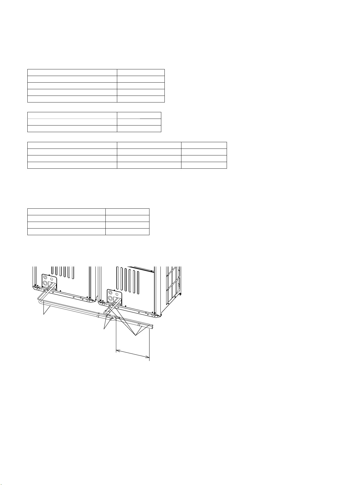
9-3. Выбор двойника-разветвителя
9-3-1. Двойник-разветвитель для внутреннего блока
Выберите соответствующий двойник-разветвитель для внутреннего блока (продается отдельно) в зависимости
от совокупной мощности внутреннего блока, в качестве справочного материала используйте таблицу ниже.
Разветвитель трубы
Общая емкость внутренних блоков Модель комплекта
200 или ниже CMY-Y102SS-G2
201 – 400 CMY-Y102LS-G2
401 – 650 CMY-Y202S-G2
651 или выше CMY-Y302S-G2
Разветвитель трубы для 1-й точки разветвления
Модели наружных блоков Модель комплекта
P450 – P650 CMY-Y202S-G2
P700 – P1350 CMY-Y302S-G2
Разветвитель коллектора
Общая емкость внутренних блоков Количество разветвителей Модель комплекта
200 или ниже 4 CMY-Y104-G
400 или ниже 8 CMY-Y108-G
650 или ниже 10 CMY-Y1010-G
* При необходимости используйте адаптер для подключения хладагентной трубки к разветвителю-двойнику иного диаметра.
9-3-2. Двойник-разветвитель для наружного блока
Выберите соответствующий двойник-разветвитель для наружного блока (продается отдельно) в зависимости
от совокупной мощности наружного блока, в качестве справочного материала используйте таблицу ниже.
Общая емкость наружных блоков Модель комплекта
P400 – P650 CMY-Y100VBK3
P700 – P900 CMY-Y200VBK2
P950 – P1350 CMY-Y300VBK3
9-4. Пример соединения труб
・Пример трубного соединения между наружными блоками
Ⓐ
Ⓑ
Ⓐ
Ⓒ
Ⓐ Трубы, прокладываемые на месте
установки
Ⓑ Двойник-разветвитель
Ⓒ Трубная секция, размещаемая перед
разветвителем-двойником, должна иметь
длину не менее 500 мм (19-11/16 д.).
KD79S703H01
RU-22
Page 75

・Пример трубного соединения между наружными блоками и внутренними блоками
От P200 до P500YKB-A1
Блок 1
Блок 1
Ⓐ
Ⓑ
Ⓒ
Ⓒ Ⓒ Ⓒ
Ⓒ
Ⓐ
Ⓑ
Ⓒ Ⓒ
От P400 до P650YSKB-A1
Блок 2Блок 1
Ⓐ Ⓐ Ⓐ Ⓐ
Ⓔ
Ⓑ
Ⓒ
ⒸⒸⒸ
Ⓒ
Ⓕ
Ⓒ Ⓒ Ⓒ
Блок 2Блок 1
Ⓔ
Ⓓ
Ⓑ
ⒸⒸ
Ⓓ
ⒸⒸⒻⒸ
От P950 до P1350YSKB-A1
Блок 3Блок 2Блок 1
Ⓐ Ⓐ Ⓐ Ⓐ Ⓐ Ⓐ
Ⓔ
Ⓔ
Ⓑ
Ⓒ
Ⓒ Ⓒ Ⓒ
Ⓒ
Ⓔ
Ⓐ Наружный блок
Ⓑ 1-е ответвление
Ⓒ Внутренний блок
Ⓓ Крышка
Ⓔ Двойник-разветвитель для наружного блока
Ⓕ Разветвитель коллектора
* Общая длина A
1, A2, A3 и A4 менее 10 м (32 фут.).
RU
Блок 3Блок 2Блок 1
Ⓕ
Ⓔ
Ⓑ
ⒸⒸ
Ⓓ
ⒸⒸⒸ
KD79S703H01
RU-23
Page 76

Трубы A, A1, A2, A3, A4 [мм]
Модель блока
Комбинационный блок Труба A Труба A
Блок 1 Блок 2 Блок 3
Жидкий
хладагент
Газообразный
хладагент
Жидкий
хладагент
3
1*
Газообразный
хладагент
Труба A2*
Жидкий
хладагент
3
Газообразный
хладагент
Труба A3*
Жидкий
хладагент
3
Газообразный
хладагент
Труба A4
Жидкий
хладагент
Газообразный
хладагент
P200YKB-A1 - - - ø9,52 ø22,2 - - - - - - - P250YKB-A1 - - - ø9,52*1ø22,2 - - - - - - - P300YKB-A1 - - - ø9,52*
2
ø22,2 - - - - - - - P350YKB-A1 - - - ø12,7 ø28,58 - - - - - - - P400YKB-A1 - - - ø12,7 ø28,58 - - - - - - - P450YKB-A1 - - - ø15,88 ø28,58 - - - - - - - P500YKB-A1 - - - ø15,88 ø28,58 - - - - - - - P400YSKB-A1 P200 P200 - ø12,7 ø28,58 ø9,52 ø22,2 ø9,52 ø22,2 - - - P450YSKB-A1 P250 P200 - ø15,88 ø28,58 ø9,52 ø22,2 ø9,52 ø22,2 - - - P500YSKB-A1 P250 P250 - ø15,88 ø28,58 ø9,52 ø22,2 ø9,52 ø22,2 - - - P550YSKB-A1 P300 P250 - ø15,88 ø28,58 ø12,7 ø22,2 ø9,52 ø22,2 - - - P600YSKB-A1 P350 P250 - ø15,88 ø28,58 ø12,7 ø28,58 ø9,52 ø22,2 - - - P650YSKB-A1 P350 P300 - ø15,88 ø28,58 ø15,88 ø28,58 ø9,52 ø22,2 - - - P700YSKB-A1 P350 P350 - ø19,05 ø34,93 ø15,88 ø28,58 ø15,88 ø28,58 - - - P750YSKB-A1 P400 P350 - ø19,05 ø34,93 ø15,88 ø28,58 ø15,88 ø28,58 - - - P800YSKB-A1 P450 P350 - ø19,05 ø34,93 ø15,88 ø28,58 ø15,88 ø28,58 - - - P850YSKB-A1 P450 P400 - ø19,05 ø41,28 ø15,88 ø28,58 ø15,88 ø28,58 - - - P900YSKB-A1 P450 P450 - ø19,05 ø41,28 ø15,88 ø28,58 ø15,88 ø28,58 - - - P950YSKB-A1 P400 P300 P250 ø19,05 ø41,28 ø15,88 ø28,58 ø12,7 ø22,2 ø12,7 ø22,2 ø19,05 ø34,93
P1000YSKB-A1 P400 P300 P300 ø19,05 ø41,28 ø15,88 ø28,58 ø12,7 ø22,2 ø12,7 ø22,2 ø19,05 ø34,93
P1050YSKB-A1 P400 P350 P300 ø19,05 ø41,28 ø15,88 ø28,58 ø12,7 ø28,58 ø12,7 ø22,2 ø19,05 ø34,93
P1100YSKB-A1 P400 P350 P350 ø19,05 ø41,28 ø15,88 ø28,58 ø12,7 ø28,58 ø12,7 ø28,58 ø19,05 ø34,93
P1150YSKB-A1 P450 P350 P350 ø19,05 ø41,28 ø15,88 ø28,58 ø15,88 ø28,58 ø15,88 ø28,58 ø19,05 ø34,93
P1200YSKB-A1 P450 P400 P350 ø19,05 ø41,28 ø15,88 ø28,58 ø15,88 ø28,58 ø15,88 ø28,58 ø19,05 ø34,93
P1250YSKB-A1 P450 P450 P350 ø19,05 ø41,28 ø15,88 ø28,58 ø15,88 ø28,58 ø15,88 ø28,58 ø19,05 ø34,93
P1300YSKB-A1 P450 P450 P400 ø19,05 ø41,28 ø15,88 ø28,58 ø15,88 ø28,58 ø15,88 ø28,58 ø19,05 ø34,93
P1350YSKB-A1 P450 P450 P450 ø19,05 ø41,28 ø15,88 ø28,58 ø15,88 ø28,58 ø15,88 ø28,58 ø19,05 ø34,93
Трубы A, A1, A2, A3, A4 [д.]
Модель блока
Комбинационный блок Труба A Труба A
Блок 1 Блок 2 Блок 3
Жидкий
хладагент
Газообразный
хладагент
Жидкий
хладагент
3
1*
Газообразный
хладагент
Труба A2*
Жидкий
хладагент
3
Газообразный
хладагент
Труба A3*
Жидкий
хладагент
3
Газообразный
хладагент
Труба A4
Жидкий
хладагент
Газообразный
хладагент
P200YKB-A1 - - - ø3/8 ø7/8 - - - - - - - P250YKB-A1 - - - ø3/8*
P300YKB-A1 - - - ø3/8*
1
ø7/8 - - - - - - - -
2
ø7/8 - - - - - - - P350YKB-A1 - - - ø1/2 ø1-1/8 - - - - - - - P400YKB-A1 - - - ø1/2 ø1-1/8 - - - - - - - P450YKB-A1 - - - ø5/8 ø1-1/8 - - - - - - - P500YKB-A1 - - - ø5/8 ø1-1/8 - - - - - - - P400YSKB-A1 P200 P200 - ø1/2 ø1-1/8 ø3/8 ø7/8 ø3/8 ø7/8 - - - P450YSKB-A1 P250 P200 - ø5/8 ø1-1/8 ø3/8 ø7/8 ø3/8 ø7/8 - - - P500YSKB-A1 P250 P250 - ø5/8 ø1-1/8 ø3/8 ø7/8 ø3/8 ø7/8 - - - P550YSKB-A1 P300 P250 - ø5/8 ø1-1/8 ø1/2 ø7/8 ø3/8 ø7/8 - - - P600YSKB-A1 P350 P250 - ø5/8 ø1-1/8 ø1/2 ø1-1/8 ø3/8 ø7/8 - - - P650YSKB-A1 P350 P300 - ø5/8 ø1-1/8 ø5/8 ø1-1/8 ø3/8 ø7/8 - - - P700YSKB-A1 P350 P350 - ø3/4 ø1-3/8 ø5/8 ø1-1/8 ø5/8 ø1-1/8 - - - P750YSKB-A1 P400 P350 - ø3/4 ø1-3/8 ø5/8 ø1-1/8 ø5/8 ø1-1/8 - - - P800YSKB-A1 P450 P350 - ø3/4 ø1-3/8 ø5/8 ø1-1/8 ø5/8 ø1-1/8 - - - P850YSKB-A1 P450 P400 - ø3/4 ø1-5/8 ø5/8 ø1-1/8 ø5/8 ø1-1/8 - - - P900YSKB-A1 P450 P450 - ø3/4 ø1-5/8 ø5/8 ø1-1/8 ø5/8 ø1-1/8 - - - P950YSKB-A1 P400 P300 P250 ø3/4 ø1-5/8 ø5/8 ø1-1/8 ø1/2 ø7/8 ø1/2 ø7/8 ø3/4 ø1-3/8
P1000YSKB-A1 P400 P300 P300 ø3/4 ø1-5/8 ø5/8 ø1-1/8 ø1/2 ø7/8 ø1/2 ø7/8 ø3/4 ø1-3/8
P1050YSKB-A1 P400 P350 P300 ø3/4 ø1-5/8 ø5/8 ø1-1/8 ø1/2 ø1-1/8 ø1/2 ø7/8 ø3/4 ø1-3/8
P1100YSKB-A1 P400 P350 P350 ø3/4 ø1-5/8 ø5/8 ø1-1/8 ø1/2 ø1-1/8 ø1/2 ø1-1/8 ø3/4 ø1-3/8
P1150YSKB-A1 P450 P350 P350 ø3/4 ø1-5/8 ø5/8 ø1-1/8 ø5/8 ø1-1/8 ø5/8 ø1-1/8 ø3/4 ø1-3/8
P1200YSKB-A1 P450 P400 P350 ø3/4 ø1-5/8 ø5/8 ø1-1/8 ø5/8 ø1-1/8 ø5/8 ø1-1/8 ø3/4 ø1-3/8
P1250YSKB-A1 P450 P450 P350 ø3/4 ø1-5/8 ø5/8 ø1-1/8 ø5/8 ø1-1/8 ø5/8 ø1-1/8 ø3/4 ø1-3/8
P1300YSKB-A1 P450 P450 P400 ø3/4 ø1-5/8 ø5/8 ø1-1/8 ø5/8 ø1-1/8 ø5/8 ø1-1/8 ø3/4 ø1-3/8
P1350YSKB-A1 P450 P450 P450 ø3/4 ø1-5/8 ø5/8 ø1-1/8 ø5/8 ø1-1/8 ø5/8 ø1-1/8 ø3/4 ø1-3/8
*1 Используйте трубу диаметром ø12,7 (ø1/2) в случае если длина трубы от наружного блока до самого дальнего внутреннего блока
составляет 90 м (295 фут.) или более.
*2 Используйте трубу диаметром ø12,7 (ø1/2) в случае если длина трубы от наружного блока до самого дальнего внутреннего блока
составляет 40
м (131 фут.) или более.
*3 Если комбинационные блоки 1, 2 и 3 расположены в разной последовательности, как указано в таблице, используйте в этом случае
трубы соответствующей длины.
KD79S703H01
RU-24
Page 77

*4 Если длина трубы после первой точки соединения превышает 40 м (131 фут.) (≤ 90 м (295 фут.)), используйте трубу жидкого хладагента
на один размер больше для всех труб, отходящих от внутреннего блока и направленных к первой точке разветвления.
*5 Если разница высот внутренних блоков составляет 15 м (49 фут.) (≤ 30 м (98 фут.)), используйте для нижнего внутреннего блока трубу
жидкого хладагента на один размер больше, направленную от блока к первой точке разветвления.
Трубы B,C,D [мм (д.)]
Общая емкость
внутренних блоков
140 или ниже ø9,52 (ø3/8) ø15,88 (ø5/8)
141 – 200 ø9,52 (ø3/8) ø19,05 (ø3/4)
201 – 300 ø9,52 (ø3/8) ø22,2 (ø7/8)
301 – 400 ø12,7 (ø1/2) ø28,58 (ø1-1/8)
401 – 650 ø15,88 (ø5/8) ø28,58 (ø1-1/8)
651 – 800 ø19,05 (ø3/4) ø34,93 (ø1-3/8)
801 или выше ø19,05 (ø3/4) ø41,28 (ø1-5/8)
Трубы a,b,c,d,e [мм (д.)]
Показатель емкости
внутреннего блока
20, 25, 32, 40, 50 ø6,35 (ø1/4) ø12,7 (ø1/2)
63, 71, 80, 100, 125, 140 ø9,52 (ø3/8) ø15,88 (ø5/8)
200 ø9,52 (ø3/8) ø19,05 (ø3/4)
250 ø9,52 (ø3/8) ø22,2 (ø7/8)
Жидкий
хладагент
Труба
Жидкий
хладагент
Газообразный
хладагент
Труба
Газообразный
хладагент
9-5. Соединения труб и работа с клапанами
Перед нагревом запаянных секций удалите газ и масло, скопившиеся в трубах.
- В противном случае это может привести к возгоранию и последующим серьезным
травмам.
Проветривайте помещение при помощи соответствующего оборудования.
- Утечка хладагента может вызвать дефицит кислорода. При контакте газа с источником
тепла образуется токсичный газ.
Храните трубы в помещении, закрыв их с обоих концов до пайки. (соединительные
колена и другие соединения храните в пластиковом пакете).
- Попадание в холодильный контур пыли, грязи или воды может привести к ухудшению
эксплуатационных свойств холодильного масла и выходу компрессора из строя.
Сервисные клапаны должны быть закрыты до окончания заправки добавочного
количества хладагента.
- В противном случае устройство может выйти из строя.
Накройте сервисные клапаны влажным полотенцем перед спаиванием трубок во
избежание перегрева клапанов свыше 120 ºC (248 ºF).
- В противном случае это может привести к повреждению оборудования.
RU
Не допускайте обгорания кабелей и воздействия пламени на металлические
пластины при спайке труб.
- В противном
случае это может привести обгоранию или неисправностям.
Спаивайте трубы после продувки азотом во избежание окисления.
- Окисленный поток внутри труб хладагента может вызвать ухудшение качеств
холодильного масла, что впоследствии может привести к повреждению компрессора.
KD79S703H01
RU-25
Page 78

9-5-1. Демонтаж защемленных соединительных трубок
Данный блок оснащается защемленными соединительными трубками, соединенными с жидкостными и
газовыми клапанами, во избежание утечки газа.
Перед тем как подсоединить трубы хладагента к наружному блоку, выполните описанные ниже шаги с ① по ③,
чтобы снять защемленные соединительные трубки.
① Убедитесь в том, что сервисный клапан плотно закрыт (повернут по часовой стрелке
② Стравите газ из защемленных соединительных трубок и слейте все хладагентное масло. (См. Ⓔ ниже.)
③ Удалите защемленные соединительные трубки. (См. Ⓕ ниже.)
<A> Сервисный клапан хладагента (жидкого/запаянного типа)
Ⓒ
Ⓐ
Ⓓ
Ⓕ
Ⓔ
<A> <B>
O
S
Ⓐ
Ⓑ
Ⓒ
<B> Сервисный клапан хладагента (газообразного/запаянного типа)
Ⓐ Стержень клапана
Данный блок поставляется с закрытым стержнем клапана. При вакуумировании системы
или подключении трубок клапан должен быть закрыт. По завершении работ откройте
клапан. Для открытия клапана поверните стержень против часовой стрелки (90˚), и по
часовой
Ⓑ Стопорный штифт
Предотвращает поворот вала на 90˚ или более.
Ⓒ Сервисное отверстие
Вы можете залить хладагент через сервисное отверстие, стравить через него газ в
защемленных соединительных трубах или вакуумировать систему.
Ⓓ Крышка
Снимите крышку перед поворотом штока. ПО завершении установите крышку на место.
Ⓔ Отрезная секция
Ⓕ Спаянная секция защемленной соединительной трубки
стрелке для закрытия клапана.
защемленной соединительной трубки
до упора).
KD79S703H01
RU-26
Page 79

9-5-2. Соединительные трубки
・Хладагентная труба от наружного блока разветвляется на конце, затем каждое ответвление подсоединяется
к внутреннему блоку.
Способ соединения
Внутренний блок Пайка или прессование
Наружный
блок
・См. раздел 5 "Содержимое упаковки" для получения более подробной информации о поставляемых в
комплекте соединительных трубах.
・При подключении труб необходимо полностью закрыть сервисные клапаны.
・Обычно имеющиеся в продаже трубы содержат грязь и пыль. Всегда продувайте их сухим инертным газом
перед использованием.
・Соблюдайте осторожность, чтобы предотвратить попадание пыли, воды и иных загрязнений в трубы во
время установки.
・Сведите к минимуму количество сгибов. Радиус сгибов делайте максимально большим.
・Не используйте средство против окисления. Это может привести к коррозии труб и ухудшению свойств
холодильного масла. При возникновении вопросов обращайтесь в компанию Мitsubishi Electric.
・Убедитесь в том, что трубы не соприкасаются друг с другом, панелями блока или пластинами основания.
(1) При подводке труб к блоку с фронтальной части (2) При подводке труб к блоку с задней части
Труба газообразного хладагента Пайка
Труба жидкого хладагента Пайка
Разветвительная секция Пайка
<A> <B>
<A> <B>
Ⓐ
<A> Сторона жидкого хладагента
<B> Сторона газообразного хладагента
Ⓐ Трубопроводы сервисного клапана хладагента
Ⓐ
RU
KD79S703H01
RU-27
Page 80

・Подключение трубки на месте установки, а также подключение трубки к сервисному клапану
При подводке труб к блоку с фронтальной части
Сторона жидкого хладагента Сторона газообразного хладагента
P200
P250
P300
P350
P400
P450
P500
Используйте поставляемую в комплекте соединительную трубку ①.
*1
Используйте поставляемые в комплекте соединительные трубки ①
*2
и ②.
Используйте поставляемые в комплекте соединительные трубки ⑤
*3
и ③.
*4*6
Используйте поставляемые в комплекте соединительные трубки ⑤
и ④.
*5
*6
Используйте поставляемую в комплекте соединительную трубку ⑤.
Используйте поставляемое в комплекте
соединительное колено ⑥ и
соединительную трубку ⑦.
Используйте поставляемое в комплекте
соединительное колено ⑥.
При подводке труб к блоку с задней части
Сторона жидкого хладагента Сторона газообразного хладагента
P200
P250
P300
P350
P400
P450
P500
Расширьте конец трубки на месте установки. (ВД ø9,52 мм (ø3/8 д.))
*1
*2
Используйте поставляемую в комплекте соединительную трубку ②.
*3
Используйте поставляемую в комплекте соединительную трубку ③.
*4*6
Используйте поставляемую в комплекте соединительную трубку ④.
*5
*6
Расширьте конец трубки на месте установки. (ВД ø15,88 мм (ø5/8
д.))
Используйте поставляемую в комплекте
соединительную трубку ⑦.
Расширьте конец трубки на месте
установки. (ВД ø28,58 мм (ø1-1/8 д.))
<Ссылка> Размеры хладагентных трубок
Внешний трубопровод [мм (д.)] Подсоединение трубы к сервисному клапану [мм (д.)]
Жидкий хладагент Газообразный хладагент Жидкий хладагент Газообразный хладагент
P200 ø9,52 (ø3/8)
P250
P300
P350 ø12,7 (ø1/2)
P400
P450 ø15,88 (ø5/8)
P500 ø15,88 (ø5/8)
*1 При длине трубы от наружного блока до самого удаленного внутреннего блока менее 90 м (295 фут.)
*2 При длине трубы от наружного блока до самого удаленного внутреннего блока 90
*3 При длине трубы от наружного блока до самого удаленного внутреннего блока менее 40 м (131 фут.)
*4 При длине трубы от наружного блока до самого удаленного внутреннего блока 40 м (131 фут.) или более.
*5 При автономном использовании
*6 При использовании в сочетании с другими наружными блоками
*1 ø9,52 (ø3/8)
*2 ø12,7 (ø1/2)
*3 ø9,52 (ø3/8)
*4*6 ø12,7 (ø1/2)
*5 ø12,7 (ø1/2)
*6 ø15,88 (ø5/8)
ø22,2 (ø7/8)
ø28,58 (ø1-1/8)
ø9,52 (ø3/8)
ø28,58 (ø1-1/8)
ø15,88 (ø5/8)
м (295 фут.) или более
・При развальцовке внешних труб соблюдайте требования по минимальной глубине запрессовки.
Размер трубки [мм (д.)] Минимальная глубина запрессовки [мм (д.)]
ø5 (ø1/4) или больше, менее ø8 (ø3/8) 6 (1/4)
ø8 (ø3/8) или больше, менее ø12 (ø1/2) 7 (5/16)
ø12 (ø1/2) или больше, менее ø16 (ø11/16) 8 (3/8)
ø16 (ø11/16) или больше, менее ø25 (ø1) 10 (7/16)
ø25 (ø1) или больше, менее ø35 (ø1-7/16) 12 (1/2)
ø35 (ø1-7/16) или больше, менее ø45 (ø1-13/16) 14 (9/16)
KD79S703H01
RU-28
Page 81

9-5-3. Уплотнение всех отверстий вокруг труб
Закройте все отверстия для труб и проводов, не подпускайте к ним мелких животных,
избегайте попадания в них влаги или снега.
- В противном случае это может повлечь за собой утечку тока, поражение электрическим
током или возникновение неисправностей блока.
Ⓐ Пример изоляционных материалов (не поставляется в комплекте)
Ⓑ Заполните промежутки
ⒶⒷ
9-6. Проверка герметичности
Не используйте кислород, легковоспламеняемый газ или хладагент, содержащий
хлор, для проверки герметичности.
- Это может привести к взрыву. Хлор способствует ухудшению свойств холодильного масла.
По завершении установки трубки хладагента проверьте систему на утечки, выполним процедуру проверки
герметичности. При наличии утечки состав хладагента изменится, что приведет к снижению
производительности.
<Процедура проверки герметичности>
① Сервисные клапаны должны быть полностью закрыты.
② Повысьте давление в трубах хладагента через сервисные отверстия жидкостных и газовых трубок.
* Используя азот повысьте добавление до 4,15 МПа.
③ Если данная величина давления удерживается в течение одного дня и не снижается, это означает, что
проверка герметичности выполнена и утечки отсутствуют. Понижение давление указывает на наличие
утечек. Выполните поиск утечек посредством распыления течеискателя (например, Gupoflex) на
прессованные или спаянные секции.
④ Вытрите течеискатель.
Ⓕ
Ⓑ
Ⓑ
Ⓒ
LO
Ⓐ
ⒹⒺ
HI
Ⓘ
Ⓙ
Ⓐ Азот
Ⓑ К внутреннему блоку
Ⓖ
Ⓒ Штуцер манометра
Ⓓ Переключатель низкого давления
Ⓗ
Ⓔ Переключатель высокого давления
Ⓕ Сервисный клапан
Ⓖ Труба жидкого хладагента
Ⓗ Труба газообразного хладагента
Ⓘ Наружный блок
Ⓙ Сервисное отверстие
RU
KD79S703H01
RU-29
Page 82

9-7. Термоизоляция для труб
Оберните трубки специальным материалом во избежание конденсации.
- Конденсат может скапливаться и капать с внутреннего блока на потолок или пол.
Оберните трубы жидкого и газообразного хладагента по отдельности полиэтиленовой пеной. При
недостаточном количестве изоляционного материала, может образоваться конденсат. Потолочные трубы
особенно сильно подвержены конденсации, их необходимо тщательно изолировать.
9-7-1. Изоляционный материал
・Проверьте, соответствует ли изоляционный материал указанным в таблице ниже стандартам.
Размер трубки [мм (д.)]
ø6,35 (ø1/4) – ø25,4 (ø1) ø28,58 (ø1-1/8) – ø41,28 (ø1–5/8)
Толщина [мм (д.)] Мин. 10 (7/16) Мин. 15 (5/8)
Огнеупорность Мин. 120 °C (248 °F)
* В условиях высокой температуры/влажности может потребоваться использование более толстого изоляционного материала.
* Независимо от указанных вашим клиентом характеристик необходимо соблюдать приведенные в таблице значения.
Ⓑ
Ⓐ
Ⓓ
Изоляционный
материал А
Внешнее
покрытие В
* Использование полиэтилена в качестве наружного покрытия делает ненужным применение битума.
Ⓒ
Ⓔ
Стекловолокно + стальная проволока
Клеящий материал + теплостойкая полиэтиленовая пена + клейкая лента
Внутренний блок Пластиковая лента
Подпольный и наружный Водонепроницаемый брезент + бронзосодержащий битум
Наружный блок Водонепроницаемый брезент + цинковая пластина + масляная краска
Ⓐ Стальная проволока
Ⓑ Труба
Ⓒ Битумная мастика или битум
Ⓓ Изоляционный материал А
Ⓔ Внешнее покрытие В
・Не изолируйте электрические провода.
Ⓐ
Ⓑ
Ⓒ
Ⓔ
Ⓓ
Ⓔ
Ⓑ
Ⓔ
Ⓒ
Ⓓ
Ⓐ Труба жидкого хладагента
Ⓑ Труба газообразного хладагента
Ⓐ
Ⓒ Электрический провод
Ⓓ Отделочная лента
Ⓔ Изоляционный материал
・Проверьте, загерметизированы ли все трубные соединения на всем расстоянии от внутреннего блока.
KD79S703H01
RU-30
Page 83

9-7-2. Изоляция секции трубы, проходящей через стену
(1) Внутренняя стена
(скрытое отверстие)
ⒶⒷ
(2) Внешняя стена (3) Внешняя стена (открытое отверстие)
Ⓓ
Ⓒ
Ⓐ
Ⓑ
Ⓔ
Ⓑ
Ⓗ
(4) Пол (водозащита) (5) Трубопроводная шахта
на крыше
(6) Защита присутствующих в пожароопасной зоне
элементов, или элементов, проникающих через
стену
Ⓓ
Ⓕ
Ⓖ
Ⓑ
Ⓐ Рукав
Ⓑ Изоляционный материал
Ⓒ Изоляция
Ⓓ Уплотнительный материал
Ⓔ Ремень
Ⓕ Водонепроницаемый слой
Ⓖ Рукав с фланцем
Ⓗ Уплотнитель с невоспламеняемым материалом, например, цементный раствор.
Ⓘ Невоспламеняемый изоляционный материал
Ⓓ
Ⓑ
Ⓒ
Ⓕ
Ⓗ
Ⓐ
1000
(39-3/8)
1000
(39-3/8)
Ⓘ
[мм (д.)]
・При уплотнении зазоров цементным раствором накройте трубную секцию, проходящую через стену,
металлическим листом во избежание оседания изоляционного материала. Для данной секции используйте
невоспламеняемые изоляционные материалы и покрытия. (Не используйте виниловую ленту).
RU
KD79S703H01
RU-31
Page 84

9-8. Вакуумирование системы
Не используйте для продувки хладагент. Используйте вакуумный насос для продувки
системы.
- Остаточный газ, скопившийся в магистралях хладагента, может стать причиной разрыва
труб или взрыва.
Используйте вакуумный насос с обратным клапаном.
- Проникновение масла вакуумного насоса в контур охлаждения может привести к
ухудшению эксплуатационных качеств холодильного масла и повреждению компрессора.
<Принцип выполнения вакуумирования>
① Выполняйте вакуумирование системы через оба сервисных отверстия используя вакуумный насос,
сервисные клапаны должны быть закрыты.
② После достижения давления 650 Па продолжайте выполнять вакуумирование в течение минимум одного
часа.
③ После этого остановите вакуумный насос и оставьте систему на один час.
④ Проверьте, не снизился ли вакуум более чем на 130 Па.
⑤ При повышении давления более чем на 130 Па скорее всего в систему просачивается вода. Подайте в
систему осушенный азот, давление должно увеличиться на 0,05 МПа. Повторяйте шаги с ① – ⑤ до тех
пор, пока не будет достигнуто давление 130 Па или ниже. Если нужного результата не удается достичь,
выполните процедуру тройного вакуумирования, описанную ниже.
<Тройное вакуумирование>
① Выполните процедуру вакуумирования системы через оба сервисных порта, давление должно достичь
533 Па, для этого используйте вакуумный насос.
② Подайте в систему осушенный азот через выпускное сервисное отверстие, давление при этом должно
опуститься до 0 Па.
③ Выполните процедуру вакуумирования системы через впускной сервисный порта, давление должно
достичь 200 Па, для этого используйте вакуумный насос.
④ Подайте в систему осушенный азот через выпускное сервисное отверстие, давление при этом должно
опуститься до 0 Па.
⑤ Выполните процедуру вакуумирования системы через оба сервисных порта, для этого используйте
вакуумный насос.
⑥ После достижения значения давления 66,7 Па остановите вакуумный насос и оставьте систему на один
час. Значение 66,7 Па должно удерживаться минимум один час.
⑦ Проверяйте в течение минимум 30 минут не увеличивается ли давление.
Ⓓ
Ⓝ
Ⓝ
Ⓐ
LO
ⒷⒸ
HI
Ⓞ
Ⓖ
Ⓗ
Ⓚ
Ⓔ
Ⓕ
Ⓘ
Ⓜ
Ⓙ
Ⓛ
Ⓐ Штуцер манометра
Ⓑ Переключатель низкого давления
Ⓒ Переключатель высокого давления
Ⓓ Сервисный клапан
Ⓔ Труба жидкого хладагента
Ⓕ Труба газообразного хладагента
Ⓖ Сервисное отверстие
Ⓗ Трехстороннее соединение
Ⓘ Клапан (вакуумный насос)
Ⓙ Клапан (для заправки хладагента)
Ⓚ Резервуар для хладагента
Ⓛ Шкала
Ⓜ Вакуумный насос
Ⓝ К внутреннему блоку
Ⓞ Наружный блок
・Используйте тару, объем в которой можно понижать на 0,1 кг (0,1 унц.).
・Рекомендованный вакуумный манометр: ROBINAIR 14830A Thermistor Vacuum Gauge или Micron Gauge
・Не измеряйте разрежение манометром коллектора.
・Используйте вакуумный насос, способный обеспечивать вакуум величиной 65 Па (абс.) в течение пяти
м
инут.
KD79S703H01
RU-32
Page 85

9-9. Дополнительная зарядка хладагентом
Заправляйте хладагент в жидком состоянии.
- При заправке газообразного хладагента для его состав в баллоне изменится, а рабочие
показатели прибора могут ухудшиться.
Запрещается использовать заправочные баллоны при заправке хладагента.
- Использование заправочного баллона может привести к изменению состава хладагента,
что станет причиной ухудшения показателей прибора.
Количество хладагента, приведенное в таблице ниже, является тем количеством, которое заправляется на
заводе в наружные блоки. Объем, требуемый для дозаливки с учетом расширительных трубок, не
заправляется в систему, это количество хладагента необходимо добавить на месте.
Модель блока
P200 6,5 (230) P400 11,5 (406)
P250 8,0 (283) P450 11,8 (417)
P300 11,5 (406) P500 11,8 (417)
P350 11,5 (406)
Объем, заправляемый на заводе [кг (унц.)]
Модель блока
Объем, заправляемый на заводе [кг (унц.)]
Количество хладагента, представленное в таблице ниже, является максимальным количеством, которое
необходимо добавить на месте установки.
Модель блока
P200YKB-A1 22,3 (786) P400YSKB-A1 45,0 (1589)
P250YKB-A1 29,7 (1048) P450YSKB-A1 45,9 (1621)
P300YKB-A1 32,7 (1152) P500YSKB-A1 47,0 (1659)
P350YKB-A1 33,6 (1184) P550YSKB-A1 51,3 (1811)
P400YKB-A1 37,2 (1311) P600YSKB-A1 53,9 (1900)
P450YKB-A1 45,0 (1589) P650YSKB-A1 56,5 (1992)
P500YKB-A1 45,9 (1621) P700YSKB-A1 68,9 (2430)
Максимальное количество, которое
необходимо добавить [кг (унц.)]
Модель блока
P750YSKB-A1 68,9 (2430)
P800YSKB-A1 71,4 (2519)
P850YSKB-A1 73,2 (2583)
P900YSKB-A1 75,7 (2671)
P950YSKB-A1 96,9 (3421)
P1000YSKB-A1 99,9 (3527)
P1050YSKB-A1 102,9 (3634)
P1100YSKB-A1 106,0 (3740)
P1150YSKB-A1 109,0 (3847)
P1200YSKB-A1 112,0 (3954)
P1250YSKB-A1 112,0 (3954)
P1300YSKB-A1 112,0 (3954)
P1350YSKB-A1 112,0 (3954)
Максимальное количество, которое
необходимо добавить [кг (унц.)]
RU
Заправка слишком большого/малого объема хладагента может вызвать неисправность оборудования.
Заправляйте строго необходимое количество хладагента.
Запишите количество добавленного хладагента на этикетке, закрепленной на панели блока управления, это
значение потребуется при дальнейшем обслуживании.
KD79S703H01
RU-33
Page 86

9-9-1. Расчет количества добавляемого хладагента
・Количество хладагента, которое необходимо добавить, зависит от размера и общей длины труб для жидкого хладагента.
・Рассчитывайте объем хладагента, который необходимо добавить, по представленной ниже формуле.
・Округлите результат до десятичного значения 0,1 кг (0,1 унц.).
(1) Единицы измерения «м» и «кг»
<Формула>
・При длине трубы от наружного блока до самого удаленного внутреннего блока 30,5 м (100 фут.) или короче
Количество
добавляемого
хладагента (кг)
ø19,05, общая
=
длина × 0,29 (кг/м)
ø15,88, общая
+
длина × 0,2 (кг/м)
ø12,7, общая
+
длина × 0,12 (кг/м)
ø9,52, общая
+
длина × 0,06 (кг/м)
ø6,35, общая
+
длина × 0,024 (кг/м)
Модели
наружных блоков
P200 0 80 или ниже 2,0
P250 0 81 – 160 2,5
+
P300 0 161 – 330 3,0
P350 0 331 – 390 3,5
P400 0 391 – 480 4,5
P450 0 481 – 630 5,0
P500 0 631 – 710 6,0
Количество (кг)
Общая емкость подсоединенных
внутренних блоков
+
711 – 800 8,0
801 – 890 9,0
891 – 1070 10,0
1071 – 1250 12,0
1251 или выше 14,0
Количество (кг)
・При длине трубы от наружного блока до самого удаленного внутреннего блока более 30,5 м (100 фут.)
Количество
добавляемого
хладагента (кг)
ø19,05, общая
=
длина × 0,26 (кг/м)
Модели
наружных блоков
P200 0 80 или ниже 2,0
P250 0 81 – 160 2,5
+
P300 0 161 – 330 3,0
P350 0 331 – 390 3,5
P400 0 391 – 480 4,5
P450 0 481 – 630 5,0
P500 0 631 – 710 6,0
ø15,88, общая
+
длина × 0,18 (кг/м)
Количество (кг)
ø12,7, общая
+
длина × 0,11 (кг/м)
Общая емкость подсоединенных
внутренних блоков
+
711 – 800 8,0
801 – 890 9,0
891 – 1070 10,0
1071 – 1250 12,0
1251 или выше 14,0
ø9,52, общая
+
длина × 0,054 (кг/м)
Количество (кг)
ø6,35, общая
+
длина × 0,021 (кг/м)
<Пример>
Модель наружного блока: P300
Общая емкость подсоединенных внутренних блоков: 361
* См. примеры трубных соединений в разделе 9-4 для получения сведений о трубах, промаркированных представленными ниже
кодами.
A: ø12,7; 40 м
B: ø9,52; 10 м
C: ø9,52; 15 м
D: ø9,52; 10 м
a: ø9,52; 10 м
b: ø9,52; 5 м
c: ø6,35; 10 м
d: ø6,35; 10 м
e: ø9,52; 10 м
KD79S703H01
RU-34
Page 87
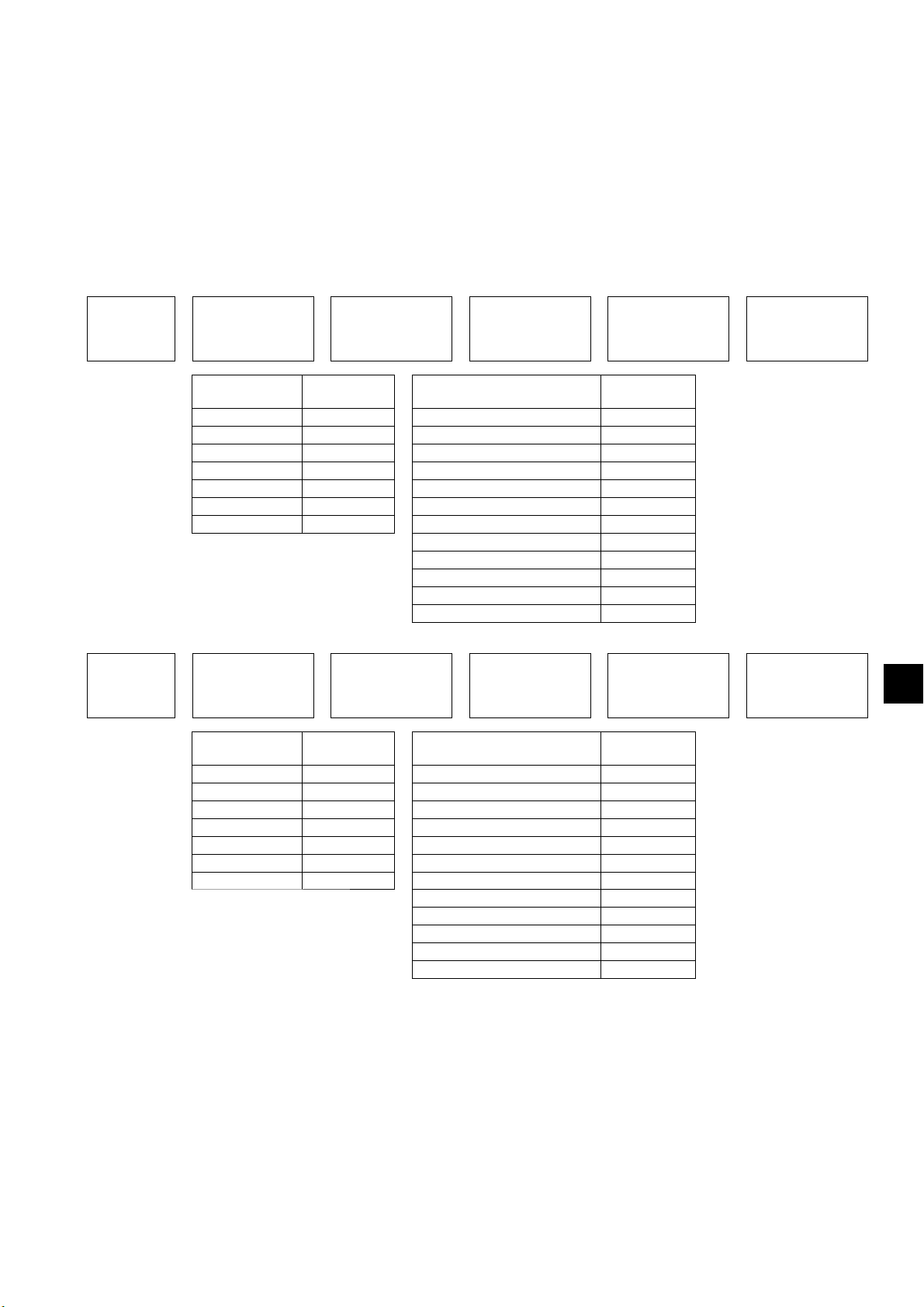
Общая длина каждой трубы жидкого хладагента:
ø12,7, общая длина: 40 (A)
ø9,52, общая длина: 10 (B) + 15 (C) + 10 (D) + 10 (a) + 5 (b) + 10 (e) = 60
ø6,35, общая длина: 10 (c) + 10 (d) = 20
При длине трубы от наружного блока до самого удаленного внутреннего блока более 30,5 м (100 фут.)
Количество добавляемого хладагента = (40 × 0,11) + (60 × 0,054) + (20 × 0,021) + 0 + 3,5
= 11,6 кг (десятичные значения округлены)
(2) Единицы измерения «фут.» и «унц.»
<Формула>
・При длине трубы от наружного блока до самого удаленного внутреннего блока 30,5 м (100 фут.) или короче
Количество
добавляемого
хладагента
(унц.)
ø3/4, общая длина
=
× 3,1 (унц./фут.)
ø5/8, общая длина
+
× 2,15 (унц./фут.)
ø1/2, общая длина
+
× 1,29 (унц./фут.)
ø3/8, общая длина
+
× 0,65 (унц./фут.)
ø1/4, общая длина
+
× 0,26 (унц./фут.)
Модели
наружных блоков
P200 0 80 или ниже 71
P250 0 81 – 160 89
+
P300 0 161 – 330 106
P350 0 331 – 390 124
P400 0 391 – 480 160
P450 0 481 – 630 177
P500 0 631 – 710 212
Количество
(унц.)
Общая емкость подсоединенных
внутренних блоков
+
711 – 800 283
801 – 890 318
891 – 1070 353
1071 – 1250 424
1251 или выше 494
Количество
(унц.)
・При длине трубы от наружного блока до самого удаленного внутреннего блока более 30,5 м (100 фут.)
Количество
добавляемого
хладагента
(унц.)
ø3/4, общая длина
=
× 2,80 (унц./фут.)
Модели
наружных блоков
P200 0 80 или ниже 71
P250 0 81 – 160 89
+
P300 0 161 – 330 106
P350 0 331 – 390 124
P400 0 391 – 480 160
P450 0 481 – 630 177
P500 0 631 – 710 212
ø5/8, общая длина
+
× 1,94 (унц./фут.)
Количество
(унц.)
ø1/2, общая длина
+
× 1,19 (унц./фут.)
Общая емкость подсоединенных
внутренних блоков
+
711 – 800 283
801 – 890 318
891 – 1070 353
1071 – 1250 424
1251 или выше 494
ø3/8, общая длина
+
× 0,58 (унц./фут.)
Количество
(унц.)
ø1/4, общая длина
+
× 0,23 (унц./фут.)
RU
KD79S703H01
RU-35
Page 88

<Пример>
Модель наружного блока: P300
Общая емкость подсоединенных внутренних блоков: 361
* См. примеры трубных соединений в разделе 9-4 для получения сведений о трубах, прома
кодами.
ркированных представленными ниже
A: ø1/2; 131 фут.
B: ø3/8; 32 фут.
C: ø3/8; 49 фут.
D: ø3/8; 32 фут.
a: ø3/8; 32 фут.
b: ø3/8; 16 фут.
c: ø1/4; 32 фут.
d: ø1/4; 32 фут.
e: ø3/8; 32 фут.
Общая длина каждой трубы жидкого хладагента:
ø1/2, общая длина: 131 (A)
ø3/8, общая длина: 32 (B) + 49 (C) + 32 (D) + 32 (a) + 16 (b) + 32 (e) = 193
ø1/4, общая длина: 32 (c) + 32 (d) = 64
При длине трубы от наружного блока до самого удаленного внутреннего блока более 30,5 м (100 фут.)
Количество добавляемого хладагента = (131 × 1,19) + (193 × 0,58) + (64 × 0,23) + 0 + 124
= 406,6 унц. (десятичные значения округлены)
9-9-2. Заправка дополнительного количества хладагента
Заправьте рассчитанное количество жидкого хладагента в блок через сервисное отверстие по завершении
прокладки труб. По завершении всех работ плотно закрутите крышки всех сервисных отверстий и стержни
клапанов во избежание утечки хладагента.
・Запрещается стравливать хладагент в атмосферу.
・Момент затяжки см. в таблице ниже.
Размер трубки
[мм (д.)]
ø9,52 (ø3/8) 22 6 4 (3/16)
ø12,7 (ø1/2) 27 10 4 (3/16)
ø15,88 (ø5/8) 32 12 4 (3/16)
ø19,05 (ø3/4) 50 30 8 (3/8)
ø25,4 (ø1) 50 30 8 (3/8)
ø28,58 (ø1-1/8) 22 - - 16
Крышка вала
(Нм)
Вал (Нм)
Размер шестигранного ключа
[мм (д.)]
Крышка сервисного
штуцера (Нм)
12
・Если резервуар хладагента не имеет сифонной трубки, для заправки следует перевернуть резервуар, как
указано на рис. ниже.
Ⓐ
Ⓐ Сифонная трубка
・После вакуумирования и зарядки хладагентом полностью откройте сервисные клапаны. Не включайте
блок при открытых клапанах.
KD79S703H01
RU-36
Page 89

10. Электромонтажные работы
Электрические работы должны выполняться только квалифицированным
персоналом в соответствии с местными нормами, а также инструкциями,
приведенными в данном руководстве. Используйте только указанные кабели и
соответствующие схемы.
- Неверный выбор уровня мощности источника питания и неправильный монтаж
электропроводки приведет к поражениям электрическим током, возникновению
неисправностей и возгоранию.
Соответствующее заземление устройства должно быть
выполнено
квалифицированными специалистами.
- Неправильное заземление может привести к поражению электрическим током,
возгоранию, взрыву или неисправности в следствие электрического шума. Не
подсоединяйте провод заземления к газопроводу, водопроводу, громоотводу или линии
заземления телефонной проводки.
10-1. Перед электромонтажными работами
・При выполнении электромонтажных работ пользуйтесь руководством по монтажу внутреннего блока или
блока управления.
・При выполнении подключений учитывайте внешние факторы (температура окружающего воздуха, прямой
солнечный свет, дождевая вода).
・При открывании или закрывании передней панели следует принять меры по предотвращению их контакта с
внутренними компонентами.
・В некоторых регионах могут предъявляться специальные требования к проводке.
・Проводка блоков разъемов наружного и внутреннего блоков должна иметь запас по длине, поскольку при
проведении технического обслуживания иногда возникает необходимость их снятия.
10-2. Характеристики силовых кабелей и устройств
RU
Силовые кабели должны прокладываться с небольшим запасом.
- В противном случае это может привести к их разрыву или перегреву, что может стать
причиной возгорания или задымления.
Установите автоматический выключатель на блок питания каждого устройства.
- В противном случае это может стать причиной поражения электрическим током.
Используйте только прерыватели с верными
значениями тока (прерыватель
замыкания на землю, вводной выключатель <переключатель + предохранитель,
отвечающий местным требованиям электробезопасности> или максимальный
прерыватель).
- В противном случае это может стать причиной поражения электрическим током,
неполадок, задымления или возгорания.
Используйте только стандартные провода питания с рекомендованными
характеристиками.
- В противном случае это может стать причиной утечки тока, перегрева
, задымления или
возгорания.
KD79S703H01
RU-37
Page 90

Затяните все клеммные винты указанным моментом.
- Ослабленные винты и неправильные соединения могут стать причиной задымления или
возгорания.
Большой ток из-за неисправности или повреждения проводки может привести к
срабатыванию автоматических выключателей защиты от утечки тока на стороне
блока и на стороне источника питания. В зависимости от важности системы отделите
систему источника питания или выполните согласование установок автоматических
выключателей.
KD79S703H01
RU-38
Page 91

・Пример
Ⓐ Прерыватель замыкания на землю
Ⓑ Вводной выключатель (максимальный
прерыватель и прерыватель замыкания
на землю)
Ⓒ Наружный блок
Ⓓ Распаячная коробка
Ⓔ Внутренний блок
Ⓕ Заземление
3 фазы~380–415 В
L1, L2, L3, N
~220–240 В
L, N
ⒷⒶ
Ⓒ
Ⓕ
ⒷⒶ
ⒺⒺⒹⒺⒺ
Ⓕ Ⓕ Ⓕ Ⓕ
・Используйте надлежащий тип максимального прерывателя. Помните, что при перегрузке по току может
присутствовать и постоянный ток.
・Выберите тип прерывателя для цепи инвертера, такого как прерыватель замыкания на землю. (Mitsubishi
Electric серии NV-S или аналогичный)
・Прерыватель замыкания на землю должен использоваться совместно с вводным выключателем.
・Устанавливайте вводной выключатель с минимальным расстоянием между контактами 3 мм (1/8 д.) на
каждом полюсе.
・Не подключайте силовые кабели L1, L2 и L3 к N. Проверьте правильность подключения фаз.
・Если провод питания поврежден, производитель, обслуживающий персонал производителя или
квалифицированный персонал должен его заменить, чтобы исключить опасность для пользователей.
・Используйте раздельные кабели питания для наружного и внутреннего блоков. Убедитесь в том, что OC и
OS снабжены раздельной проводкой.
・Размер кабеля питания, характеристики устройства и сопротивление системы (если требованиями местных
законодательств не определены иные характеристики минимального размера кабеля или характеристик
устройства, соблюдайте значения, представленные в таблице ниже).
Минимальный размер [мм2 (СРЕДН.)]
Силовой
кабель
P200 4,0 (12) – 4,0 (12)
P250 4,0 (12) – 4,0 (12)
P300 4,0 (12) – 4,0 (12)
Наружный
блок
Общий
рабочий
ток
внутренних
блоков
*1 : В качестве значения F0 используйте большее из значений F1 и F2.
F1 = Общий максимальный ток каждого внутреннего блока × 1,2
F2 = {V1 × (количество типа 1)/C} + {V1 × (количество типа 2)/C} + {V1 × (количество типа 3)/C} + {V1 × (количество типа 4)/C}
*2 : Чувствительность по току вычисляется по следующей формуле.
G1 = (V2 × количество типа 1) + (V2 × количество типа 2) + (V2 × количество типа 3) + (V2 × количество типа 4) + (V3 × длина
P350 6,0 (10) – 6,0 (10)
P400 10,0 (8) – 10,0 (8)
P450 10,0 (8) – 10,0 (8)
P500 10,0 (8) – 10,0 (8)
F0 ≤ 16 A *11,5 (16) 1,5 (16) 1,5 (16)
1
F0 ≤ 25 A *
F0 ≤ 32 A *
силового кабеля (км))
2,5 (14) 2,5 (14) 2,5 (14)
1
4,0 (12) 4,0 (12) 4,0 (12)
Силовой кабель
после точки
разветвления
Провод
заземле-
ния
Прерыватель
замыкания на землю
30 A, 100 мА, 0,1 сек.
или меньше
30 A, 100 мА, 0,1 сек.
или меньше
30 A, 100 мА, 0,1 сек.
или меньше
40 A, 100 мА, 0,1 сек.
или меньше
60 A, 100 мА, 0,1 сек.
или меньше
60 A, 100 мА, 0,1 сек.
или меньше
60 A, 100 мА, 0,1 сек.
или меньше
Чувствительность по
току 20 A *
Чувствительность по
току 30 A *
Чувствительность по
току 40 A *
2
2
2
Вводной выключатель (A)
Мощность
Плавкий
предохра-
25 25 30 (IEC 61000-3-3)
32 32 30 (IEC 61000-3-3)
32 32 30 (IEC 61000-3-3)
40 40 40 0,25 Ом
63 63 60 0,22 Ом
63 63 60 0,19 Ом
63 63 60 0,16 Ом
16 16 20 (IEC 61000-3-3)
25 25 30 (IEC 61000-3-3)
32 32 40 (IEC 61000-3-3)
нитель
Максимальный
прерыватель
(NFB) (A)
Максимально
допустимое
сопротивление
системы
RU
KD79S703H01
RU-39
Page 92

Внутренний блок V1 V2
PLFY-VBM, PMFY-VBM, PEFY-VMS, PCFY-VKM,
Тип 1
PKFY-VHM, PKFY-VKM, PFFY-VKM, PFFY-VLRMM
Тип 2 PEFY-VMA 38 1,6
Тип 3 PEFY-VMHS 13,8 4,8
Внутренний блок, не соответствующий указанному выше
Тип 4
«C» является кратным значением тока отключения при 0,01 с. Рассчитайте значение «C» исходя
из характеристик отключения выключателя, использующегося на месте установки.
<Пример расчета «F2»>
Условия: PEFY-VMS × 4 блока, PEFY-VMA × 1 блок, «C» = 8 (см. диаграмму примеров.)
F2 = 18,6 × 4/8 + 38 × 1/8
= 14,05
→ Используйте выключатель с номиналом 16 A. (Ток отключения = 8 × 16 A при 0,01 с)
Размер силового кабеля [мм2 (СРЕДН.)] V3
1,5 (16) 48
2,5 (14) 56
4,0 (12) 66
G1 Чувствительность по току
30 мА или меньше 30 мА, 0,1 сек. или меньше
100 мА или менее 100 мА, 0,1 сек. или меньше
18,6 2,4
00
Диаграмма примеров
6000
600
60
10
1
Время отключения [с]
0,1
0,01
1
Кратные значения номинального
ПРИМЕР
1086432
C
тока отключения
20
・Приведенное сечение провода соответствует минимальному значению для проводки в металлическом
трубопроводе. В случае падения напряжения следует использовать провод следующего большего
сечения. Убедитесь, что падение напряжения не превышает 10%. Убедитесь, что асимметрия
напряжений фаз составляет 2% или менее.
・Для питания устройств, предназначенных для использования вне помещений, следует применять кабели
с характеристиками не ниже гибкого кабеля с полихлоропреновой изоляцией (тип 60245 IEC57).
Например, используйте провод YZW.
・Данный блок предназначено для подключения к электросети с максимально разрешенным
сопротивлением системы в точке подключения (блок энергоснабжения) источника питания пользователя,
не превышающим значения, указанного в приведенной выше таблице.
・Пользователь обязан проследить за выполнением данного условия. При необходимости пользователь
обязан запросить
данные по сопротивлению у компании-поставщика электроэнергии.
・Данный блок соответствует стандарту IEC 61000-3-12 при условии, что мощность при коротком
1
замыкании Ssc выше или равна Ssc (*
) на стыковочном устройстве между источником пользователя и
электросетью. Ответственность по обеспечению соответствия электропитания данным требованиям
(мощность короткого замыкания Ssc выше или равна Ssc (*1)) лежит на пользователе или установщике
оборудования (при необходимости пользователь или установщик обязан проконсультироваться со
специалистами компании-поставщика электроэнергии).
*1 Ssc
Модель Ssc (МВА)
P200 1,39
P250 1,54
P300 1,91
P350 2,43
P400 2,82
P450 3,26
P500 3,83
KD79S703H01
RU-40
Page 93

10-3. Характеристики кабеля дистанционного управления
・Кабель передачи данных
Тип 2-жильный экранированный кабель CVVS, CPEVS или MVVS
Размер 1,25 мм
Длина Макс. 200 м (656 фут.)
Примечания
* Не используйте один многожильный кабель для соединения внутренних блоков разных систем хладагента. Использование одного
многожильного кабеля может привести к ошибкам в передаче данных и последующим неисправностям.
* Удлиненная секция кабеля также должна быть тщательно экранирована.
2
(СРЕДН. 16), или ø1,2 мм или больше
Максимально допустимая длина кабеля передачи данных для внешних блоков (оба кабеля передачи данных
центрального пульта управления и наружные/внутренние кабели передачи данных) составляет 500 м (1640 фут.).
Максимально допустимая длина кабелей передачи данных от источника питания до каждого наружного блока
или до пульта системы
составляет 200 м (656 фут.).
・Кабель пульта дистанционного управления
Кабель пульта дистанционного управления ME Кабель пульта дистанционного управления MA
Тип Изолированный 2-жильный кабель (неэкранированный) CVV
Размер
Длина
(0,75–1,25 мм2 (СРЕДН. 18–16) при соединении с простым пультом дистанционного управления)
Макс. 10 м (32 фут.)
* Если длина превышает 10 м (32 фут.),
воспользуйтесь экранированным проводом
сечением 1,25 мм
2
(СРЕДН. 16).
0,3–1,25 мм
2
(СРЕДН. 22–16)
Макс. 200 м (656 фут.)
10-4. Конфигурация системы
・Код блока и максимальное количество подключаемых блоков
Тип блока Код Количество подключаемых блоков
Наружный блок
Внутренний блок IC 1 – 26 блоков на OC
Пульт дистанционного управления RC 0 – 2 блока на группу
Усилитель сигнала RP 0 – 1 блок на OC
* В зависимости от количества подсоединенных внутренних блоков может понадобиться усилитель сигнала.
* Наружные блоки одной системы хладагента, автоматически определяются как OC, OS1, OS2. Наружные блоки определяются как OC,
OS1 и OS2 в порядке снижения
этом случае – в порядке возрастания номеров).
Основной блок OC –
Подчиненный блок OS1, OS2 –
уровня производительности (если два или более блоков имеют одинаковую производительность, в
RU
KD79S703H01
RU-41
Page 94

・Пример конфигурации системы
* Величины в скобках на представленных ниже рисунках означают номера.
(1) При подключении пультов дистанционного управления ME
* Переместите перемычку из
положения CN41 в
положение CN40. *
* SW5-1: ON *
1
2
Ⓐ
Группа 3Группа 1
Группа 5
Ⓐ Экранированный
кабель
Ⓑ Пульт
дистанционного
управления
подчиненного блока
Ⓒ Пульт системы
* Установите перемычку
Ⓑ
питания в положение
CN41.
* SW5-1: ON *
2
Ⓒ
*1 Если блок питания не подключен к кабелю централизованной системы управления, переместите перемычку из положения CN41
в положение CN40 только на одном внешнем блоке.
*2 Если используется пульт системы, переведите выключатель SW5-1 всех наружных блоков в положение ON.
Максимально допустимая длина кабелей пульта управления
Кабели передачи данных для наружных блоков L1 + L2 + L3 + L4, L1 + L2 + L3 + L5, L1 + L2 + L6 ≤ 500 м (1640 фут.)
Кабели передачи данных L
Кабели пульта дистанционного управления
1, L3 + L4, L3 + L5, L6, L2 + L6 ≤ 200 м (656 фут.)
1, ℓ2, ℓ3, ℓ4 ≤ 10 м (32 фут.)
ℓ
* В случае превышения значения длины 10 м (32 фут.), избыточную длину
необходимо включать в максимально допустимую длину кабелей
передачи данных выше.
KD79S703H01
RU-42
Page 95

(2) При подключении пультов дистанционного управления MА
* Переместите перемычку из
положения CN41 в
положение CN40. *
* SW5-1: ON *
1
2
Ⓐ
Ⓐ Экранированный
Группа 5Группа 3Группа 1
кабель
Ⓑ Пульт
дистанционного
управления
подчиненного блока
Ⓒ Пульт системы
* Установите перемычку
Ⓑ
питания в положение
CN41.
* SW5-1: ON *
2
Ⓒ
*1 Если блок питания не подключен к кабелю централизованной системы управления, переместите перемычку из положения CN41
в положение CN40 только на одном внешнем блоке.
*2 Если используется пульт системы, переведите выключатель SW5-1 всех наружных блоков в положение ON.
*3 При подключении PAR-31MAA к группе подключение других пультов
дистанционного управления MA к этой группе невозможно.
Максимально допустимая длина кабелей пульта управления
Кабели передачи данных для наружных блоков L1 + L2 + L3 + L4, L1 + L2 + L6 ≤ 500 м (1640 фут.)
Кабели передачи данных L
Кабели пульта дистанционного управления m
1, L3 + L4, L6, L2 + L6 ≤ 200 м (656 фут.)
1 + m2, m1 + m2 + m3 + m4 ≤ 200 м (656 фут.)
(3) В случае подключения усилителя сигнала
Заземление
TB7 TB7 TB7
RU
Ⓐ
Ⓐ Экранированный кабель
*1 Клеммы (TB3) наружных блоков одной холодильной системы подсоединяются друг к другу последовательно.
*2 Установите перемычку питания в положение CN41.
Максимально допустимая длина кабелей пульта управления
Кабели передачи данных
Кабели пульта дистанционного управления
KD79S703H01
L1 + L2 + L3 + L5 + L6, L1 + L2 + L3 + L5 + L7, L1 + L2 + L4, L6 + L5 + L3 + L4,
L4 + L3 + L5 + L7 ≤ 200 м (656 фут.)
ℓ
1, ℓ2 ≤ 10 м (32 фут.)
* В случае превышения значения длины 10 м (32 фут.), избыточную длину
необходимо включать в максимально допустимую длину кабелей
передачи данных выше.
RU-43
Page 96

10-5. Подключение проводов блока управления
Соединения на клеммах должны быть надежно затянуты соответствующим
моментом.
- Неправильное подключение кабелей может привести к их разрыву или перегреву, что
может стать причиной возгорания или задымления.
10-5-1. Прокладка кабеля питания через выбивное отверстие
・Проделайте отверстия в нижней части фронтальной панели молотком.
Ⓐ
Ⓐ Кабельный хомут
Ⓑ
Ⓒ
Ⓑ Силовой кабель
Ⓒ Кабель передачи данных
・Заполните свободное пространство вокруг проводов подходящим материалом.
・При прокладке силового кабеля через выбивное отверстие без использования кабелепровода, удалите
острые выступы отверстия и обмотайте кабель защитным материалом.
・Трубой для прокладки электрических проводов уменьшите диаметр выбивного отверстия, чтобы
предотвратить проникновение в блок мелких животных.
・При извлечении трубы для прокладки электрических проводов из нижней части блока закройте отверстие
для трубы, чтобы предотвратить проникновение внутрь воды.
KD79S703H01
RU-44
Page 97

10-5-2. Крепление кабеля
Блок выводов источника питания
Кабельный хомут
Резиновая втулка
Плата
M-NET
Блок выводов линии
передачи данных
Кабельный хомут
Кабельная стяжка
(поставляется в комплекте)
Силовой кабель
(не поставляется в комплекте)
Кабель передачи данных
(не поставляется в комплекте)
Проводка блока (проводка датчика)
Кабельная стяжка
(поставляется в комплекте)
Резиновая втулка
① Пропустите кабель питания через резиновую втулку с левой стороны. (См. *1 и *2 ниже.)
② Пропустите провода блока (провода датчика) и кабель передачи данных через резиновую втулку с
правой стороны. (См. *1 и *2 ниже.)
③ Кабельными хомутами закрепите кабель питания и кабель передачи данных.
④ Закрепите обе резиновые втулки прилагаемыми стяжками. (См. *3 ниже.)
*1 Убедитесь, что все кабели проходят внутри резиновой втулки.
Вид сверху
Проводка
Резиновая втулка
Проводка
Вид сверху
*2 В время пропускания кабелей через резиновую втулку следите за тем, чтобы втулка не слетела с листового металла экрана блока
управления.
Разрез
Резиновая втулка
(овальная часть)
Резиновая втулка
(овальная часть)
Вид в поперечном разрезе
Кабели выходят за пределы резиновой втулки.
Проводка
RU
Листовой металл
экрана
Резиновая втулка
Листовой металл
экрана
Резиновая втулка
*3 При закреплении резиновой втулки прилагаемым ремнем не оставляйте зазора между краями втулки.
Кабельная
стяжка
Наложение
краев втулки
Прим. 20 мм (13/16 д.)
Разрез на
резиновой втулке
<Задняя часть резиновой втулки>
Зазор между
краями резиновой
втулки.
Разрез на
резиновой
втулке
<<Важная информация>>
При закреплении резиновой втулки ремнем убедитесь, что края
втулки накладываются друг на друга, как показано на рис. слева.
* Зазор между краями втулки может привести к попаданию внутрь
снега или воды, что вызовет повреждение оборудования.
KD79S703H01
RU-45
Page 98

10-5-3. Подключение кабелей
Ⓐ
Ⓑ
L1 L2 L3 N
Ⓒ
ⒹⒺ
Ⓐ Блок управления
Ⓑ Блок выводов источника питания (TB1)
Ⓒ Кабель передачи данных
Ⓓ Блок выводов (ТВ3) кабеля передачи данных
«внутренний блок - наружный блок»
Ⓔ Блок выводов кабеля передачи данных
центрального пульта (TB7)
Ⓒ
ⒶⒷ
Ⓓ
Ⓑ
Ⓐ
Ⓔ
Ⓒ
Ⓐ Кабели питания, кабели передачи данных
Ⓑ Гирляндное подключение (только кабели передачи данных)
Ⓒ Блоки вывода (TB1, TB3, TB7)
Ⓓ Нанесите установочную риску.
Ⓔ Установите круглые клеммы тыльными сторонами друг к другу.
Ⓐ Блок вывода с незатянутыми винтами
Ⓑ Правильно установленный блок вывода
Ⓒ Пружинные шайбы должны быть расположены параллельно блоку вывода.
・Подсоедините кабели к блоку выводов источника питания и блоку выводов линии передачи данных
соответственно. Неправильное подсоединение вызовет неисправность системы.
・Не подключайте кабель питания к блоку вывода линии передачи данных. Это приведет к выходу из строя
электрических компонентов.
・Перед тем как подключить провод к выводу TB7, убедитесь, что напряжение составляет не более 20 В
пост. тока.
・Кабели передачи данных должны быть расположены на расстоянии 5 см (2 д.) или более от силового
кабеля во избежание негативного воздействия помех от силового кабеля. (Не размещайте кабели
передачи данных и кабель питания в одном кабелепроводе).
・Соблюдайте момент затяжки каждого типа винта, см. ниже. Не затягивайте винты чрезмерно большим
моментом, это может привести к их повреждению.
Блок вывода (TB1 (винт M6)): 2,5–2,9 [Нм]
Блок вывода (TB3, TB7 (винт M3,5)): 0,82–1,0 [Нм]
・При затяжке винтов не нажимайте слишком сильно на головку во избежание повреждения винта.
・Нанесите установочную риску перманентным маркером вдоль головки винта, шайбы и клеммы после
затягивания винта.
① Подключите внутренний-наружный кабель передачи данных к клемме TB3.
Если наружные блоки составляют единую систему хладагента, последовательно подключите их выводы
TB3 (M1, M2, заземление). Подсоедините кабель передачи данных между внутренним блоком и
наружным блоком для наружных блоков к выводам TB3 (M1, M2, заземление) одного из наружных
блоков. Экранируйте клемму заземления.
② Подключите кабели передачи данных централизованного пульта управления (между централизованной
системой управления и наружными блоками разных систем охлаждения) к TB7.
Если наружные блоки составляют единую систему хладагента, последовательно подключите их выводы
TB7 (M1, M2, S) ко всем наружным блокам. *1 Экранируйте клемму S.
*1 Если выводы ТВ7 наружных блоков единой системы не подключены последовательно, подсоедините кабель передачи данных
центрального пульта к выводу TB7 на OC. Если OC неисправен или центральный пульт подключался в момент отключения
электричества, подсоедините последовательно выводы TB7 OC, OS1 и OS2. (если наружный блок, перемычка питания CN41
которого на пульте управления была заменена на CN40, неисправна или отсутствует питание, централизованное управление не
будет выполняться, даже если выводы TB7 подключены последовательно).
③ Если блок питания не подключен к кабелю централизованной системы управления, переместите
перемычку из положения CN41 в положение CN40 только на одном внешнем блоке.
④ На внешнем блоке, перемычка питания которого была заменена с CN41 на CN40, дополнительно
подсоедините клемму S и клемму заземления.
⑤ Подсоедините выводы M1 и M2 блока выводов передачи данных внутреннего блока с последним
адресом в одной группе с блоком выводов пульта дистанционного управления.
⑥ Если используется пульт системы, переведите выключатель SW5-1 всех наружных блоков в положение
ON.
⑦ Кабельными хомутами надежно закрепите кабели в нижней части блока выводов.
KD79S703H01
RU-46
Page 99

10-6. Назначения адреса
・Установите переключатели адресов следующим образом.
Способ назначения адреса Адрес
Внутренний блок (главный,
подчиненный)
Наружный блок (OC, OS1, OS2)
Пульт
дистанционного
управления ME
Пульт дистанционного
управления МА
* Наружные блоки одной системы хладагента, автоматически определяются как OC, OS1, OS2. Наружные блоки определяются как OC,
OS1 и OS2 в порядке снижения уровня производительности
этом случае – в порядке возрастания номеров).
* Выполните назначение адреса для группы внутреннего блока при помощи пультов дистанционного управления после включения
питания всех блоков.
Главный
Подчиненный
Назначьте самый последний адрес главного внутреннего блока в группе, затем
назначьте последовательные адреса остальным внутренним блокам той же группы.
Назначьте последовательные адреса наружным блокам одной системы хладагента.
* Для назначения адреса 100 установите переключатель адреса в положение 50.
Назначьте адрес, соответствующий адресу главного внутреннего блока группы
плюс 100.
Назначьте адрес, соответствующий адресу главного внутреннего блока группы
плюс 150.
Назначение адреса не требуется. (Требуется назначение для главного/
подчиненного блока).
(если два или более блоков имеют одинаковую производительность, в
01 - 50
51 – 100
101 – 150
151 – 200
–
RU
KD79S703H01
RU-47
Page 100

11. Тестовый запуск
11-1. Перед тестовым запуском
По завершении монтажа электропроводки измерьте сопротивление изоляции, оно
должно составлять минимум 1 МОм.
- В противном случае это может стать причиной утечки тока, неполадок или возгорания.
Подключите электропитание не менее чем за 12 часов до начала работы. В течение
рабочего сезона питание устройства должно быть включено.
- Недостаточная мощность может стать причиной повреждения
・Перед выполнение тестового запуска выключите питание наружного блока и отключите кабель питания от
блока вывода источника питания для измерения сопротивления изоляции.
・Омметром 500 В измерьте сопротивление изоляции между блоком выводов источника питания и землей.
Убедитесь, что сопротивление составляет не менее 1 МОм.
・Если сопротивление изоляции ниже 1 MОм или же выше, подключите кабель питания к блоку вывода
источника питания, затем включите питание минимум за 12 часов до запуска блока. Если сопротивление
изоляции ниже 1 MОм, не включайте блок, проверьте заземление компрессора.
・Пока блок включен, компрессор будет находиться под напряжением даже после его остановки.
・Сопротивление изоляции между блоком вывода источника питания и заземления может упасть до 1 MОм
сразу же после установки или в случае отключения питания блока в течение длительного времени простоя
хладагента в компрессоре.
・При включении питания и подаче напряжения на блок в течение 12 часов или дольше хладагент в
компрессоре испарится и сопротивление изоляции возрастет.
・Не применяйте напряжение омметра на блок вывода для кабелей передачи данных. Это может привести к
повреждению платы управления.
・Не измеряйте сопротивление изоляции блока вывода передачи данных пульта дистанционного управления.
・Проверьте, нет ли утечки хладагента, также проверьте плотно ли подключены кабели питания и кабели
передачи данных.
・Проверьте, полностью ли открыты сервисные клапаны стороны жидкого и газообразного хладагента.
Затяните штуцеры клапанов.
・Проверьте последовательность фаз источника питания и межфазное напряжение. Если напряжение больше
±10%, или же если небаланс напряжения составляет более 2%, обратитесь к заказчику.
・При подключении усилителя сигнала включите усилитель сигнала перед тем, как включать наружный блок.
При выключении сначала наружного блока, сведения о подключении контура хладагента не удастся
проверить. В случае выключения сначала наружного блока включите усилитель сигнала, затем
перезапустите наружный блок.
・Если блок питания не подключен к кабелю централизованной системы управления, или в случае если
питание подается через пульт системы с использованием функции подачи питания, выполните тестовый
запуск при включенном блоке питания. Установите перемычку питания в положение CN41.
・В случае включения питания или после восстановления подачи питания, производительность может быть
пониженной примерно в течение 30 минут.
.
KD79S703H01
RU-48
 Loading...