

Mitsubishi Electric PUHY-P-YHM-A, PUHY-EP-YHM-A, PUHY-P-YHM-A-BS, PUHY-EP-YHM-A-BS Installation Manual
Page 1

Air-Conditioners For Building Application
OUTDOOR UNIT
PUHY-P-YHM-A (-BS)
PUHY-EP-YHM-A (-BS)
For use with R410A
PO
HG
SV
CZ
TR
RU
GR
P
NL
I
E
F
D
SL
INSTALLATION MANUAL
For safe and correct use, please read this installation manual thoroughly before installing the air-conditioner unit.
INSTALLATIONSHANDBUCH
Zum sicheren und ordnungsgemäßen Gebrauch der Klimageräte das Installationshandbuch gründlich durchlesen.
MANUEL D’INSTALLATION
Veuillez lire le manuel d’installation en entier avant d’installer ce climatiseur pour éviter tout accident et vous assurer d’une utilisation correcte.
MANUAL DE INSTALACIÓN
Para un uso seguro y correcto, lea detalladamente este manual de instalación antes de montar la unidad de aire acondicionado.
MANUALE DI INSTALLAZIONE
Per un uso sicuro e corretto, leggere attentamente questo manuale di installazione prima di installare il condizionatore d’aria.
INSTALLATIEHANDLEIDING
Voor een veilig en juist gebruik moet u deze installatiehandleiding grondig doorlezen voordat u de airconditioner installeert.
MANUAL DE INSTALAÇÃO
Para segurança e utilização correctas, leia atentamente este manual de instalação antes de instalar a unidade de ar condicionado.
EΓXEIPI∆IO O∆HΓIΩN EΓKATAΣTAΣHΣ
Για ασφάλεια και σωστή χρήση, παρακαλείστε διαβάσετε προσεχτικά αυτ το εγχειρίδιο εγκατάστασης πριν αρχίσετε την
εγκατάσταση της µονάδας κλιµατισµού.
РУКОВОДСТВО ПО УСТАНОВКЕ
Для осторожного и правильного использования прибора необходимо тщательно ознакомиться с данным руководством по
установке до выполнения установки кондиционера.
MONTAJ ELKMONTAJ ELK
MONTAJ ELKMONTAJ ELK
MONTAJ ELK
WW
WW
W
TABITABI
TABITABI
TABI
Emniyetli ve doqru biçimde naswl kullanwlacaqwnw öqrenmek için lütfen klima cihazwnw monte etmeden önce bu elkitabwnw dikkatle okuyunuz.
GB
Page 2
2
(mm)
6
[Fig. 6.0.1]
[Fig. 7.0.1]
1 P200 ~ P300
EP200
7
(2)
(1)
(3)
(4)
[Fig. 6.0.2]
<A> : Top view
<B> : Side view
<C> : When there is little space up to an obstruction
A :Front
B : Unit height
C :Back
D : Air outlet guide (Procured at the site)
A :Front
B : Must be open
C :Wall height (H)
2 P350 ~ P450
EP300
15
*
15
*
450
*
300
*
<A>
A
100
*
450
*
50
*
50
*
<A>
A
A
B
<B>
500
H
h
h
H
240
45°
A
D
C
50
<C>
1000
30
450
*
300
*
C
BB
C
A
100
450
*
100
*
BB
C
C
A
450
*
100*
CC
B
A
A
A
B
450 450
15
*
C
AAA
450 450
900
300
*
300
*
BB
C
C
A
1000
*
900 300
*
B
B
C
A
(mm)
8m
8m
40°
8m
40°
8m
Page 3
3
8
[Fig. 8.1.1]
<A> Without detachable leg
A : M10 anchor bolt procured at the site.
B :Corner is not seated.
C : Fixing bracket for hole-in anchor bolt (3 locations to fix
with screws).
D : Detachable leg
30mm
A
B
C
9
9.2
[Fig. 9.2.1]
[P200 ~ P450]
[EP200, EP300]
A : Outdoor unit
B : First branch
C : Indoor unit
D : Cap
E : Outdoor twinning kit
[P500 ~ P900]
[EP400 ~ EP650]
[P950 ~ P1250]
[EP700 ~ EP900]
B
E
A
A2A1
A
B C D
e
a b c d
C
C
CC
C
unit 2
A
unit 1
E
A
A
2
A
1
A
unit 2
A
unit 1
B
a
b
c d e
C
D
CC
C
C
B
A
B C D
e
a b c d
C
C
CC
C
A
B
A
a
b
c d e
C
D
CC
C
C
A
B
B C D
e
a b c d
C
C
CCC
E
A3
A4
A2
unit 3
A
AA
unit 2unit 1
E
A1
A
E
A
3
A
4
A
2
A
unit 3
A
AA
unit 2unit 1
E
A
1
B
a
b
c d e
C
D
CC
C
C
A
[Fig. 8.1.2]
A : Screws
30mm
A
D
B
C D
<B> With detachable leg
Page 4
4
A (mm)
Å Outdoor model
P200
P250
P300
P350
P400
P450
P500
P550
P600
P650
P700
P750
P800
P850
P900
P950
P1000
P1050
P1100
P1150
P1200
P1250
EP200
EP300
EP400
EP450
EP500
EP550
EP600
EP650
EP700
EP750
EP800
EP850
EP900
unit 1
-
-
-
-
-
P250
P300
P350
P350
P350
P400
P450
P450
P450
P400
P400
P400
P400
P450
P450
P450
-
-
EP200
P250
EP300
EP300
EP300
P350
EP300
EP300
EP300
EP300
EP300
unit 2
-
-
-
-
-
P250
P250
P250
P300
P350
P350
P350
P400
P450
P300
P300
P350
P350
P350
P400
P450
-
-
EP200
EP200
EP200
P250
EP300
EP300
EP200
P250
EP300
EP300
EP300
unit 3
-
-
-
-
-
-
-
-
-
-
-
-
-
-
P250
P300
P300
P350
P350
P350
P350
-
-
-
-
-
-
-
-
EP200
EP200
EP200
P250
EP300
ı Liquid pipe
ø9.52
*1 ø9.52
*2 ø9.52
ø12.7
ø12.7
ø15.88
ø15.88
ø15.88
ø15.88
ø15.88
ø19.05
ø19.05
ø19.05
ø19.05
ø19.05
ø19.05
ø19.05
ø19.05
ø19.05
ø19.05
ø19.05
ø19.05
ø9.52
*2 ø9.52
ø12.7
ø15.88
ø15.88
ø15.88
ø15.88
ø15.88
ø19.05
ø19.05
ø19.05
ø19.05
ø19.05
Ç Gas pipe
ø19.05
ø22.2
ø22.2
ø28.58
ø28.58
ø28.58
ø28.58
ø28.58
ø28.58
ø28.58
ø34.93
ø34.93
ø34.93
ø41.28
ø41.28
ø41.28
ø41.28
ø41.28
ø41.28
ø41.28
ø41.28
ø41.28
ø19.05
ø22.2
ø28.58
ø28.58
ø28.58
ø28.58
ø28.58
ø28.58
ø34.93
ø34.93
ø34.93
ø41.28
ø41.28
ı Liquid pipe
-
-
-
-
-
ø9.52
ø12.7
ø12.7
ø12.7
ø12.7
ø15.88
ø15.88
ø15.88
ø15.88
ø15.88
ø15.88
ø15.88
ø15.88
ø15.88
ø15.88
ø15.88
-
ø9.52
ø9.52
ø12.7
ø12.7
ø12.7
ø12.7
ø12.7
ø12.7
ø12.7
ø12.7
ø12.7
Ç Gas pipe
-
-
-
-
-
ø22.2
ø22.2
ø28.58
ø28.58
ø28.58
ø28.58
ø28.58
ø28.58
ø28.58
ø28.58
ø28.58
ø28.58
ø28.58
ø28.58
ø28.58
ø28.58
-
ø22.2
ø22.2
ø22.2
ø22.2
ø22.2
ø28.58
ø22.2
ø22.2
ø22.2
ø22.2
ø22.2
ı Liquid pipe
-
-
-
-
-
ø9.52
ø9.52
ø9.52
ø12.7
ø12.7
ø12.7
ø12.7
ø15.88
ø15.88
ø12.7
ø12.7
ø12.7
ø12.7
ø12.7
ø15.88
ø15.88
-
ø9.52
ø9.52
ø9.52
ø9.52
ø12.7
ø12.7
ø9.52
ø9.52
ø12.7
ø12.7
ø12.7
Ç Gas pipe
-
-
-
-
-
ø22.2
ø22.2
ø22.2
ø22.2
ø28.58
ø28.58
ø28.58
ø28.58
ø28.58
ø22.2
ø22.2
ø28.58
ø28.58
ø28.58
ø28.58
ø28.58
-
ø22.2
ø22.2
ø22.2
ø22.2
ø22.2
ø22.2
ø22.2
ø22.2
ø22.2
ø22.2
ø22.2
ı Liquid pipe
-
-
-
-
-
-
-
-
-
-
-
-
-
-
ø9.52
ø12.7
ø12.7
ø12.7
ø12.7
ø12.7
ø12.7
-
-
-
-
-
-
-
ø9.52
ø9.52
ø9.52
ø9.52
ø12.7
Ç Gas pipe
-
-
-
-
-
-
-
-
-
-
-
-
-
-
ø22.2
ø22.2
ø28.58
ø28.58
ø28.58
ø28.58
ø28.58
-
-
-
-
-
-
-
ø22.2
ø22.2
ø22.2
ø22.2
ø22.2
ı Liquid pipe
-
-
-
-
-
-
-
-
-
-
-
-
-
-
ø19.05
ø19.05
ø19.05
ø19.05
ø19.05
ø19.05
ø19.05
-
-
-
-
-
-
-
ø19.05
ø19.05
ø19.05
ø19.05
ø19.05
Ç Gas pipe
-
-
-
-
-
-
-
-
-
-
-
-
-
-
ø34.93
ø34.93
ø34.93
ø34.93
ø34.93
ø34.93
ø34.93
-
-
-
-
-
-
-
ø34.93
ø34.93
ø34.93
ø34.93
ø34.93
Unit combination A A1 *3 A2 *3 A3 *3 A4
9.2
9
*1 ø12.7 for over 90m
*2 ø12.7 for over 40m
*3 The pipe sizes listed in columns A1 to A3 in this table correspond to the
sizes for the models listed in the unit 1, 2, and 3 columns. When the order
of the models for unit 1, 2, and 3 change, make sure to use the appropriate
pipe size.
Ô 4-Branching header
(Downstream unit
model total
<
=
200)
CMY-Y104-G
8-Branching header
(Downstream unit
model total
<
=
400)
CMY-Y108-G
Ò
10-Branching header
(Downstream unit
model total
<
=
650)
CMY-Y1010-G
Å Outdoor model
P500 ~ P650
EP400 ~ EP650
P700 ~ P900
P950 ~ P1250
EP700 ~ EP900
˜
Outdoor twinning kit
CMY-Y100VBK2
CMY-Y200VBK2
CMY-Y300VBK2
B, C, D (mm)
a, b, c, d, e (mm)
Ï Downstream unit model total
~ 200
201 ~ 400
401 ~ 650
Ó The 1st branch of P450 ~ P650
651 ~
È
The 1st branch of P700, P750, P800
Ì Joint
CMY-Y102S-G2
CMY-Y102L-G2
CMY-Y202-G2
CMY-Y302-G2
Î Total capacity of indoor units
~ 140
141 ~ 200
201 ~ 300
301 ~ 400
401 ~ 650
651 ~ 800
801 ~
ı Liquid pipe
ø9.52
ø9.52
ø9.52
ø12.7
ø15.88
ø19.05
ø19.05
Ç Gas pipe
ø15.88
ø19.05
ø22.2
ø28.58
ø28.58
ø34.93
ø41.28
‰ Model number
20,25,32,40,50
63,71,80,100,125,140
200
250
ı Liquid pipe
ø6.35
ø9.52
ø9.52
ø9.52
Ç Gas pipe
ø12.7
ø15.88
ø19.05
ø22.2
Page 5
5
9.2
9
[Fig. 9.2.2]
A
C
F
B
C
F
<A> Make sure the pipes from the twinning pipe to the outdoor unit are
sloped downwards (towards the twinning pipes).
F
C
2m
F
D
E
C
<B> When the piping on the outdoor unit side (from the twinning pipe)
exceeds 2 m, ensure a trap (gas pipe only) within 2 m.
<C> Slope of twinning pipes
±15°
F
G
<D> Pipe connection example
H
I
H
J
A : Downward slope
B : Upward slope
C : Indoor unit
D :Trap (gas pipe only)
E : Within 2 m
F :Twinning pipe
G :
Slope of the
twinning
pipe is at an angle within ±15° to the gro
und
H : Pipes on site
I :Twinning kit
J : Straight run of pipe that is 500 mm or more
Page 6
6
2468 0
1234567 890A
1 1
111
111
11 1 1
1111 1
1111
1111
111
1357 9A
10.2
10
[Fig. 10.2.1]
C
A
B
D
<A> Refrigerant service valve
(liquid side/brazed type)
<B> Refrigerant service valve
(gas side/brazed type)
[Fig. 10.2.3]
AB
A : Example of closure materials (field supply)
B : Fill the gap at the site
No.
C Shape
No.
C Shape
PUHY-P200YHM-A
PUHY-EP200YHM-A
PUHY-P250YHM-A
PUHY-P300YHM-A
PUHY-EP300YHM-A
PUHY-P350YHM-A
PUHY-P400YHM-A
PUHY-P450YHM-A
[Fig. 10.2.2]
<A> Front pipe routing
678
<C>
A
B
12
<C>
A09
<C>
543
<C>
678
<C>
*5
345
<C>
*1~*4
A
B
<B> Bottom pipe routing
IDø19.05
ODø19.05
ODø9.52
IDø12.7
ODø12.7
IDø15.88
ODø22.2
IDø25.4
IDø9.52
ODø9.52
IDø15.88
ODø15.88
IDø25.4
ODø25.4
ODø9.52
IDø15.88
ODø19.05
IDø25.4
ODø28.58
IDø25.4
IDø12.7
ODø12.7
A : Service port
B : Shaft
C : Cap
D : Connecting pipe brazing portion
<A> Front pipe routing <B> Bottom pipe routing
<C> Included with outdoor unit
A Gas pipe (field supply required) B Liquid pipe (field supply required)
C Shape
*1 P200, P250, EP200: Expand the liquid pipe (ID9.52) and connect directly to the valve. <field supply required>
*2 P300: To use in combination with other outdoor units, expand the liquid pipe (ID12.7) and connect directly to the valve. <field supply required>
*3 P450: Expand the liquid pipe (ID15.88) and connect directly to the valve. <field supply required>
*4 P400: To use in combination with other outdoor units, expand the liquid pipe (ID15.88) and connect directly to the valve. <field supply required>
*5 P200: Expand the gas pipe (ID19.05) and connect directly to the valve. <field supply required>
Page 7

7
[Fig. 10.3.1]
[Fig. 10.3.3]
[Fig. 10.3.2]
10.3
A
A : Nitrogen gas
B :To indoor unit
C : System analyzer
D : Low knob
E : Hi knob
F :Valve
G : Liquid pipe
H : Gas pipe
I : Outdoor unit
J : Service port
A : System analyzer
B : Low knob
C : Hi knob
D :Valve
E : Liquid pipe
F : Gas pipe
G : Service port
H : Three-way joint
I :Valve
J :Valve
K : R410A cylinder
L : Scale
M :Vacuum pump
N :To indoor unit
O : Outdoor unit
A : Syphon pipe
D
C
C
B
B
E
F
G
H
I
J
A
LOW
HI
LOW
HI
B
A
K
J
L
H
M
C
D
EN
N
O
F
G
I
10.4
[Fig. 10.4.4]
[Fig. 10.4.3][Fig. 10.4.2]
C
A
B
D
E
[Fig. 10.4.1]
B
A
D
C
E
E
E
D
A
B
A B
<A> Inner wall (concealed)
A B
D
C
<B> Outer wall
A : Steel wire B : Piping
C : Asphaltic oily mastic or asphalt
D : Heat insulation material A
E : Outer covering B
A : Liquid pipe B : Gas pipe
C : Electric wire D : Finishing tape
E : Insulator
D
F
G
B
<D> Floor (waterproofing)
E
I
B
<C> Outer wall (exposed)
F
H
D
B
G
<E> Roof pipe shaft
I
A
J
1m1m
<F> Penetrating portion on fire
limit and boundary wall
A : Sleeve B : Heat insulating material
C :Lagging D : Caulking material
E : Band F :Waterproofing layer
G : Sleeve with edge H : Lagging material
I : Mortar or other incombustible caulking
J : Incombustible heat insulation material
B In case of the R410A cylinder having no syphon pipe.
Page 8

8
C
L1 L2 L3 N
Terminal block for indoor –
outdoor transmission line
(TB3)
Terminal block for
centralized control
(TB7)
Power supply terminal block
(TB1)
Control box
A
B
[Fig. 11.2.1]
11.3
11.2
[Fig. 11.2.2]
A
B
C
[Fig. 11.3.1]
11
A : Power source
B :Transmission line
C : Earth screw
A BC
E
D
M1M2
M1M2
S
TB7
TB3
IC
(51)
M1 M2 S
TB5
RC
(01)
IC
M1 M2 S
TB5
(02)
IC
M1 M2 S
TB5
(04)
IC
M1 M2 S
TB5
(03)
IC
M1 M2 S
TB5
(05)
IC
M1 M2 S
TB5
(07)
IC
M1 M2 S
TB5
(06)
L
2
L
1
(101)
RC
(105)
RC
(103)
RC
(155)
OC
M1M2
M1M2
S
TB7
TB3
CN40
(52)
OC
r
3
ABS
System
controller
L
3
L
6
L
4
L
5
r
2
r
4
r
1
AB AB AB
A
B
CN40
A : Cable strap
B : Power source line
C :Transmission line
*1: When the power supply unit is not connected to the transmission line for centralized control, disconnect the male power supply
connector (CN41) from ONE outdoor unit in the system and connect it to CN40.
*2: If a system controller is used, set SW2-1 on all of the outdoor units to ON.
<A> Change the jumper connec-
tor from CN41 to CN40 *1
<B> SW2-1:ON *2
( ) Address
<C> Keep the jumper connector
on CN41
<B> SW2-1:ON *2
Page 9

9
A BC
E
D
M1 M2
M1 M2
M1M2
S
TB7
TB3
IC
(51)
M1 M2 1 2S
TB5
TB15
12
TB15
12
TB15
12
TB15
12
TB15
12
TB15
MA
(01)
IC
M1 M2 S
TB5
(02)
IC
M1 M2 S
TB5
(04)
IC
M1 M2 S
TB5
(03)
IC
M1 M2 S
TB5
(05)
IC
M1 M2 S
TB5
(07)
IC
M1 M2 S
TB5
(06)
L
2
L
1
MAMAMA
OC
M1M2
S
TB7
TB3
(52)
OC
c
1
c
4
c
3
S
System
controller
L
3
L
6
L
4
c
2
ABABAB
AB
A
B
c
2
c
1
c
1
c
2
CN40
CN40
[Fig. 11.3.2]
A : Group 1
B : Group 3
C : Group 5
D : Shielded wire
E : Sub remote
controller
( ) Address
<A> Change the jumper connec-
tor from CN41 to CN40 *1
<B> SW2-1:ON *2
<C> Keep the jumper connector
on CN41
<B> SW2-1:ON *2
[Fig. 11.3.3]
RC
IC
M1M2 S
TB5
IC
M1M2 S
TB5
RP
Ground
AB
ABAB
S
TB2
ABS
TB3
L
4
r
1
r
1
M1M2
TB3
M1M2
TB3
M1M2
M1M2 S
TB3
TB7
M1M2 S
TB7
M1M2 S
TB7
OC
(51)
L
7
RC
IC
M1M2 S
TB5
IC
M1M2 S
TB5
L
6
L
5
L
3
L
2
L
1
OS1
(52)
OS2
(53)
To another
refrigerant system
[Fig. 11.4.1]
A : Switch (Breakers for
wiring and current
leakage)
B : Breakers for current
leakage
C : Outdoor unit
D : Pull box
E : Indoor unit
BA
C
3N~380–415V
L1, L2, L
3,
N
BA
~220–240V
L, N
PE
PE
PE
E
PE PE
E
D
E E
( ) Address
11.4
Page 10

116
RU
1.1. До установки и монтажа проводки
X Перед установкой системы необходимо внимательно
ознакомиться с разделом “Меры предосторожности”.
X Раздел “Меры предосторожности” содержит важную
информацию по безопасности. Правила безопасности
следует соблюдать в обязательном порядке.
Символы, используемые в тексте
Предупреждение:
Несоблюдение данных предупреждений может привести к
травмированию людей или летальному исходу.
Внимание:
Несоблюдение данных инструкций может привести к выходу
оборудования из строя.
Символы, используемые в иллюстрациях
: Служит для обозначения действий, запрещенных к выполнению.
: Служит для обозначения инструкций, подлежащих выполнению.
: Служит для обозначения узла, который должен быть заземлен.
: Указывает на опасность поражения электрическим током. (Данный
символ отображается на предупреждающей наклейке, закрепленной
на основном блоке.) <Цвет: желтый>
Предупреждение:
Внимательно ознакомьтесь с содержанием
предупреждающих табличек на основном блоке.
ПРЕДУПРЕЖДЕНИЕ О ВЫСОКОМ НАПРЯЖЕНИИ:
В блоке управления содержатся узлы под высоким напряжением.
При открывании передней панели следует принять меры к
исключению их контакта с внутренними компонентами.
Перед тем как приступить к осмотру внутренней части блока
управления, необходимо отключить питание не менее, чем на 10
минут, и убедиться в том, что напряжение между блоками FT-P и
FT-N на
плате инвертора упало ниже 20 вольт.
(Помните, что после выключения питания в системе в течение 10
минут сохраняется опасное для жизни напряжение.)
Предупреждение:
Установка кондиционера воздуха должна производиться силами
специалистов дилерского центра либо другим специалистом,
обладающим соответствующей квалификацией.
- Ненадлежащая установка самим пользователем может стать причиной
утечки воды, поражения электрическим током, возгорания и т.д.
Монтаж должен осуществляться на таком месте, которое является
достаточно прочным, чтобы выдержать вес кондиционера.
- Невыполнение данного условия может привести
к падению
кондиционера и травмированию людей.
Для проводки используйте только специальные кабели. Убедитесь
в надежности подсоединения и в том, что внешние силы,
прикладываемые к кабелю, не передаются на клеммы.
- Ненадлежащим образом выполненные подсоединения и слабая
затяжка могут вызвать нагрев и последующее возгорание.
Монтаж производится в специально предназначенном месте, с
запасом
прочности на случай сильных ветров и землетрясений.
- Нарушение правил монтажа может привести к падению кондиционера
и травмированию людей.
Фильтры и аксессуары, указанные компанией Mitsubishi Electric,
должны использоваться в обязательном порядке.
•
•
•
•
•
•
•
•
- Для установки аксессуаров необходимо обратиться к помощи
квалифицированного специалиста. Ненадлежащая установка самим
пользователем может стать причиной утечки воды, поражения
электрическим током, возгорания и т.д.
Запрещается ремонтировать кондиционер самостоятельно. При
необходимости выполнения ремонта следует обратиться в дилерский центр.
- Ненадлежащим образом выполненный ремонт может стать причиной
утечки воды, поражения электрическим током, возгорания и т.д.
Запрещается прикасаться к ребрам теплообменника.
-
Нарушение правил обращения с изделием может стать причиной травмирования.
При возникновении утечки хладагента во время проведения
монтажных работ необходимо проветрить помещение.
- В результате контактирования хладагента с открытым огнем
происходит выделение ядовитых газов.
Установка кондиционера воздуха должна производиться в полном
соответствии с Руководством по установке.
- Ненадлежащим образом выполненная установка может стать причиной
утечки воды, поражения электрическим током, возгорания и т
.д.
Все работы, связанные с электричеством, должны выполняться
квалифицированным электриком в полном соответствии с “Электротехническими
стандартами” и “Нормами проведения внутренней проводки” и инструкциями,
указанными в Руководстве по установке. Характеристики электропитания должны
строго соответствовать рекомендованным.
- Несоответствие характеристик подаваемого питания рекомендованным
или нарушение правил установки могут привести с сбоям в работе
кондиционера, поражению электрическим током или возгоранию.
Надежно установите крышку (панель) разъемов наружного блока.
- Неправильная установка крышки (панели) наружного блока приведет
к попаданию пыли и воды в наружный блок, что может послужить
причиной возгорания или поражения
электрическим током.
При установке или переноске кондиционера воздуха на другое
место для его заправки следует применять только хладагент,
рекомендованный к применению с данным кондиционером.
- Использование иного хладагента, а также проникновение воздуха
в систему приведет к нарушениям его циркуляции и выходу
кондиционера из строя.
При установке кондиционера воздуха в небольшом помещении
следует предварительно провести измерения и убедиться в том, что
в случае аварийной утечки в этом помещении не будет превышена
предельно допустимая концентрация паров хладагента.
- Для получения информации по размерам помещения обратитесь
в дилерский центр. Превышение концентрации паров хладагента
в случае его аварийной утечки повлечет за собой недопустимое
снижение содержания кислорода
в воздухе.
Перед проведением работ по перемещению или повторной его
установке необходимо проконсультироваться с сотрудниками
дилерского центра или квалифицированным специалистом.
- Ненадлежащим образом выполненная установка может стать причиной
утечки воды, поражения электрическим током, возгорания и т.д.
После окончания монтажных работ следует убедиться в
отсутствии утечки хладагента.
- Контакт хладагента с
нагревательными приборами, кухонной плитой и
иными источниками тепла может привести к выделению токсичных газов.
Запрещается вносить любые изменения в конструкцию защитных
устройств и изменять их настройки.
- Короткое замыкание реле давления, теплового реле и иных защитных
устройств, приложение к ним физического воздействие, равно
как применение компонентов, отличных от указанных компанией
Mitsubishi Electric, может
привести к возгоранию или взрыву.
По вопросам, связанным с утилизацией данного изделия следует
обращаться в дилерский центр.
Мастер монтажа и электрик должны обеспечить защиту
системы от протечек в соответствии с требованиями местного
законодательства и стандартов.
- Характеристики проводки и основного выключателя питания
применимы в том случае, если отсутствуют местные стандарты.
Особое
внимание необходимо уделять области установки изделия,
и особенно его основанию, где возможно скопление паров
охлаждающего газа, который тяжелее воздуха.
•
•
•
•
•
•
•
•
•
•
•
•
•
•
1. Меры предосторожности
Содержание
1. Меры предосторожности ........................................................................116
1.1. До установки и монтажа проводки ........................................116
1.2.
Меры предосторожности для приборов, в которых используется хладагент R410A
..... 117
1.3. Перед установкой ...................................................................117
1.4. Перед монтажом или переносом проводки ..................................117
1.5. Перед началом тестового запуска .................................................117
2. Информация об изделии ........................................................................117
3. Комбинация наружных блоков ...............................................................118
4. Технические характеристики ..................................................................118
5. Подтверждение комплектности .............................................................119
6. Требования к пространству вокруг блока ..............................................119
7. Способ поднимания ................................................................................119
8. Установка блока ..................................................................................... 120
8.1. Установка ............................................................................... 120
9. Установка трубопроводов ...................................................................... 120
9.1. Внимание ............................................................................... 120
9.2. Установка трубопроводов хладагента ......................................121
10. Зарядка дополнительного количества хладагента .............................. 121
10.1. Расчет
необходимого количества хладагента ..................... 121
10.2. Меры предосторожности при соединении труб и работе с
клапанами .............................................................................. 122
10.3. Проверка на герметичность, вакуумирование и зарядка
хладагентом ........................................................................... 123
10.4. Термоизоляция труб хладагента .......................................... 123
11. Проводка (Для получения информации см. руководство по установке
каждого блока и пульта управления.) ................................................... 124
11.1. Внимание ............................................................................... 124
11.2. Панель управления и места подсоединения проводки ...... 124
11.3. Подсоединение кабелей передачи данных ................................. 124
11.4. Подсоединение
основной проводки питания и
характеристики оборудования .............................................. 126
12. Тестовый запуск ..................................................................................... 127
12.1.
Следующие явления не являются признаками неисправностей
. .. 127
13. Информация на табличке параметров ................................................. 127
Page 11

117
RU
такого оборудования создаваемым шумом, который нарушает ход
медицинских процедур или радиовещания.
Не устанавливайте изделие на конструкции, которые могут вызвать утечку.
- При влажности в помещении свыше 80% или при засорении дренажной
трубы с внутреннего блока может капать конденсат. Дренаж внутреннего
и наружного блоков выполняется одновременно, по необходимости.
1.4.
Перед монтажом или переносом проводки
Внимание:
Заземлите изделие.
-
Не подсоединяйте провод заземления к газовой трубе, водяной трубе,
громоотводу или линии заземления телефонной проводки. Неправильно
выполненное заземление может стать причиной поражения электрическим током.
Соблюдайте полярность.
Запрещается подсоединять провода питания L1, L2 и L3 к выводу N.
- Если подключение проводки выполнено неправильно, при подаче
напряжения некоторые электрические компоненты могут выйти из строя.
Проложите сетевой кабель так, чтобы он не был натянут.
- Натяжение может привести к разрыву кабеля и стать причиной
перегрева и возгорания.
Надлежащим образом установите основной автоматический выключатель.
-
Отсутствие выключателя может привести к поражению электрическим током.
Используйте провода питания с рекомендованными характеристиками.
-
Кабели слишком малой мощности могут прогореть, вызвать перегрев и пожар.
Используйте автоматический выключатель и предохранитель с
рекомендованными характеристиками.
- Использование автоматического выключателя или предохранителя
большего номинального тока, а также применение самодельных
устройств может привести к выходу изделия из строя или возгоранию.
Запрещается мыть блок кондиционера.
-
Невыполнение этого требования может привести к поражению электрическим током.
В течение всего срока эксплуатации следует проверять состояние
монтажного основания кондиционера.
- Потеря свойств основания может привести к падению блока с
возможным травмированием людей или порчей имущества.
Для обеспечения правильного дренирования установка дренажных трубок
должна производиться в полном соответствии с Руководством по установке.
Во избежание конденсации влаги трубы должны быть изолированы.
- Неправильная установка дренажной системы может привести к утечке
воды и порче мебели или иного личного имущества.
Будьте очень внимательным при транспортировке изделия.
-
Запрещается переносить изделие силами одного человека. Его масса превышает 20 кг.
- Для упаковки некоторых изделий используются пластиковые ленты.
Не применяйте их для транспортировки. Это опасно.
-
Запрещается прикасаться к ребрам теплообменника. Вы можете порезаться.
- При перемещении наружного прибора подвешивайте его в указанных
точках основания прибора. Также поддерживайте его в четырех
точках, чтобы исключить соскальзывание.
Утилизируйте упаковочные материалы с соблюдением правил безопасности.
- Такие упаковочные материалы, как гвозди и другие металлические
или деревянные предметы, могут причинить порезы и иные травмы.
- Порвите пластиковый упаковочный пакет и утилизируйте так, чтобы
он был недоступен детям. Не позволяйте детям играть с пластиковой
упаковкой, это грозит летальным исходом от удушения.
1.5. Перед началом тестового запуска
Внимание:
Подключите электропитание не менее чем за 12 часов до начала работы.
- Запуск сразу после подключения сетевого питания может серьезно
повредить внутренние комоненты изделия. Сетевой выключатель
должен оставаться включенным в течение всего периода эксплуатации
изделия. Строго соблюдайте полярность всех подключений.
Не прикасайтесь к выключателям мокрыми руками.
- Прикосновение к выключателю мокрыми руками может привести к
поражению электрическим током.
Не прикасайтесь к трубам хладагента
во время работы и сразу
после выключения прибора.
- В течение и сразу после эксплуатации прибора трубы хладагента
могут быть горячими или холодными, в зависимости от условий
протекающего в трубах, компрессоре и других компонентах
холодильного контура. Вы можете обжечь или обморозить руки при
прикосновении к трубам хладагента.
Не используйте кондиционер воздуха, если его панели и крышки сняты.
-
Движущиеся, горячие части или части под напряжением могут причинить травму.
Не отключайте питание немедленно после выключения прибора.
- Следует выждать не менее пяти минут до отключения питания. Иначе
может возникнуть утечка воды и иные неисправности.
Во время обслуживания не прикасайтесь к компрессору.
- Если питание подключено, то нагревательное устройство,
расположенное в основании компрессора, может работать.
•
•
•
•
•
•
•
•
•
•
•
•
•
•
•
•
•
•
Необходимо с особой тщательностью выбирать место установки
изделий с наружным блоком, снабженным функцией подачи наружного
воздуха во внутренний блок, поскольку при отключении термостата
наружный воздух может беспрепятственно попадать в помещение.
- Подача наружного воздуха в помещение может иметь нежелательные
последствия для людей или продуктов питания.
1.2.
Меры предосторожности для приборов, в
которых используется хладагент R410A
Внимание:
Не используйте имеющиеся трубы хладагента.
- Использование старых труб хладагента и старого масла охлаждения,
содержащих большие количества хлора, может привести к порче
масла охлаждения нового прибора.
- R410A является хладагентом высокого давления, что может привести
к разрыву существующих труб.
Используйте трубы из раскисленной фосфором меди и бесшовные
трубы, выполненные из латуни. Кроме этого
убедитесь, что внутренняя
и внешняя поверхность труб чистая, без частиц серы, окисей, пыли/
грязи, частиц стружки, масел, влаги или других загрязнений.
- Загрязнение внутренней поверхности труб хладагента может вызвать
ухудшение качеств компрессорного масла.
Храните предназначенные для установки трубы в помещении,
герметически закрытыми с обоих концов до припайки. (изменения
и другие соединения
храните в пластиковом пакете.)
- Попадание в контур охлаждения пыли, грязи или воды, может
привести к ухудшению эксплуатационных качеств масла и выходу
компрессора из строя.
Нанесите небольшое количество сложного или простого эфира или
алкилбензола на патрубки и фланцевые соединения. (для внутренних блоков)
- Масло охлаждения потеряет свои свойства при смешивании с
большим количеством минерального масла.
Используйте для зарядки системы жидкий хладагент.
- При использовании газообразного хладагента для зарядки системы,
состав хладагента в баллоне изменится, а рабочие показатели
прибора могут ухудшиться.
Разрешается использовать исключительно хладагент R410A.
- При использовании другого агента (например, R22 в смеси с R410A)
наличие
в нем хлора может привести к ухудшению эксплуатационных
качеств холодильного масла.
Используйте вакуумный насос с обратным клапаном.
- Проникновение масла вакуумного насоса в контур охлаждения может
привести к ухудшению эксплуатационных качеств холодильного масла.
Запрещается использовать следующие инструменты,
применяемые с обычными видами хладагента.
(Штуцер манометра, заправочный шланг, течеискатель, обратный
клапан, заправочное основание
, оборудование для сбора хладагента)
- Попадание обычного хладагента и холодильного масла в R410A
может привести к ухудшению эксплуатационных свойств хладагента.
- Попадание воды R410A приведет к ухудшению эксплуатационных
свойств холодильного масла.
- Поскольку в состав R410A хлорин не входит, течеискатели,
используемые для работы с обычными хладагентами, не применимы.
Запрещается использовать заправочные баллоны.
- Использование заправочного
баллона может привести к ухудшению
эксплуатационных свойств хладагента.
При работе с инструментом следует принимать меры предосторожности.
- Попадание в холодильный контур пыли, грязи или воды может
привести к ухудшению эксплуатационных свойств хладагента.
1.3. Перед установкой
Внимание:
Запрещается устанавливать этот блок в местах, где возможна
утечка огнеопасных газов.
- Утечка газа и его скопление возле кондиционера может привести к взрыву.
Не используйте кондиционер в местах хранения продуктов
питания, точных инструментов, произведений искусств, а также
местах нахождения домашних животных и растений.
- Это може вызвать, например, порчу продуктов питания.
Не
используйте кондиционер воздуха в особых условиях эксплуатации.
- Наличие масел, пара, испарений серы и т.д. может вызвать
значительное ухудшение рабочих показателей кондиционера или
выход его компонентов из строя.
При установке прибора в больнице, на станции связи или в
аналогичном помещении обеспечьте достаточную защиту от шума.
- Преобразовательное оборудование, частный электрогенератор,
высоковольтное медицинское оборудование или оборудование для
радиосвязи могут вызвать сбой в работе кондиционера или его
отключение. С другой стороны, кондиционер может мешать работе
•
•
•
•
•
•
•
•
•
•
•
•
•
•
•
2. Информация об изделии
В данном изделии применяется хладагент R410A.
Схема трубных соединений систем, использующих хладагент R410A
может отличаться от систем, использующих хладагенты обычного типа,
поскольку рабочее давление систем, использующих R410A, выше. Для
получения дополнительной информации см. технические характеристики.
Некоторые инструменты и устройства, применяемые для монтажа
систем с другими типами хладагента, не могут использоваться
с системами, в которых
используется R410A. Для получения
дополнительной информации см. технические характеристики.
•
•
•
Использование старых труб с остатками хлора, который содержится в обычном
холодильном масле и хладагенте, может привести к порче холодильного
масла хладагента нового прибора Наличие хлора вызовет ухудшение свойств
холодильного масла новой установки. Также существующие трубы не могут
быть использованы по причине более высокого рабочего давления в системах,
использующих R410A, что может привести
к разрыву труб.
Внимание:
Запрещается стравливать R410A в атмосферу.
Согласно Киотскому протоколу, R410A является фреоносодержащим газом с
потенциалом глобального потепления (ПГП) = 1975.
•
•
•
Page 12

118
RU
3. Комбинация наружных блоков
Ниже приведены кассетные модели, с PUHY-P500 до P1250.
Модели наружной установки Кассетные модели
PUHY-P200YHM-A(-BS) - - PUHY-P250YHM-A(-BS) - - PUHY-P300YHM-A(-BS) - - PUHY-P350YHM-A(-BS) - - PUHY-P400YHM-A(-BS) - - PUHY-P450YHM-A(-BS) - - PUHY-P500YSHM-A(-BS) PUHY-P250YHM-A(-BS) PUHY-P250YHM-A(-BS) PUHY-P550YSHM-A(-BS) PUHY-P300YHM-A(-BS) PUHY-P250YHM-A(-BS) PUHY-P600YSHM-A(-BS) PUHY-P350YHM-A(-BS) PUHY-P250YHM-A(-BS) PUHY-P650YSHM-A(-BS) PUHY-P350YHM-A(-BS) PUHY-P300YHM-A(-BS) PUHY-P700YSHM-A(-BS) PUHY-P350YHM-A(-BS) PUHY-P350YHM-A(-BS) PUHY-P750YSHM-A(-BS) PUHY-P400YHM-A(-BS) PUHY-P350YHM-A(-BS) PUHY-P800YSHM-A(-BS) PUHY-P450YHM-A(-BS) PUHY-P350YHM-A(-BS) PUHY-P850YSHM-A(-BS) PUHY-P450YHM-A(-BS) PUHY-P400YHM-A(-BS) PUHY-P900YSHM-A(-BS) PUHY-P450YHM-A(-BS) PUHY-P450YHM-A(-BS) PUHY-P950YSHM-A(-BS) PUHY-P400YHM-A(-BS) PUHY-P300YHM-A(-BS) PUHY-P250YHM-A(-BS)
PUHY-P1000YSHM-A(-BS) PUHY-P400YHM-A(-BS) PUHY-P300YHM-A(-BS) PUHY-P300YHM-A(-BS)
PUHY-P1050YSHM-A(-BS) PUHY-P400YHM-A(-BS) PUHY-P350YHM-A(-BS) PUHY-P300YHM-A(-BS)
PUHY-P1100YSHM-A(-BS) PUHY-P400YHM-A(-BS) PUHY-P350YHM-A(-BS) PUHY-P350YHM-A(-BS)
PUHY-P1150YSHM-A(-BS) PUHY-P450YHM-A(-BS) PUHY-P350YHM-A(-BS) PUHY-P350YHM-A(-BS)
PUHY-P1200YSHM-A(-BS) PUHY-P450YHM-A(-BS) PUHY-P400YHM-A(-BS) PUHY-P350YHM-A(-BS)
PUHY-P1250YSHM-A(-BS) PUHY-P450YHM-A(-BS) PUHY-P450YHM-A(-BS) PUHY-P350YHM-A(-BS)
Ниже приведены кассетные модели, с PUHY-EP400 до EP900.
Модели наружной установки Кассетные модели
PUHY-EP200YHM-A(-BS) - - PUHY-EP300YHM-A(-BS) - - PUHY-EP400YSHM-A(-BS) PUHY-EP200YHM-A(-BS) PUHY-EP200YHM-A(-BS) PUHY-EP450YSHM-A(-BS) PUHY-P250YHM-A(-BS) PUHY-EP200YHM-A(-BS) PUHY-EP500YSHM-A(-BS) PUHY-EP300YHM-A(-BS) PUHY-EP200YHM-A(-BS) PUHY-EP550YSHM-A(-BS) PUHY-EP300YHM-A(-BS) PUHY-P250YHM-A(-BS) PUHY-EP600YSHM-A(-BS) PUHY-EP300YHM-A(-BS) PUHY-EP300YHM-A(-BS) PUHY-EP650YSHM-A(-BS) PUHY-P350YHM-A(-BS) PUHY-EP300YHM-A(-BS) PUHY-EP700YSHM-A(-BS) PUHY-EP300YHM-A(-BS) PUHY-EP200YHM-A(-BS) PUHY-EP200YHM-A(-BS)
PUHY-EP750YSHM-A(-BS) PUHY-EP300YHM-A(-BS) PUHY-P250YHM-A(-BS) PUHY-EP200YHM-A(-BS)
PUHY-EP800YSHM-A(-BS) PUHY-EP300YHM-A(-BS) PUHY-EP300YHM-A(-BS) PUHY-EP200YHM-A(-BS)
PUHY-EP850YSHM-A(-BS) PUHY-EP300YHM-A(-BS) PUHY-EP300YHM-A(-BS) PUHY-P250YHM-A(-BS)
PUHY-EP900YSHM-A(-BS) PUHY-EP300YHM-A(-BS) PUHY-EP300YHM-A(-BS) PUHY-EP300YHM-A(-BS)
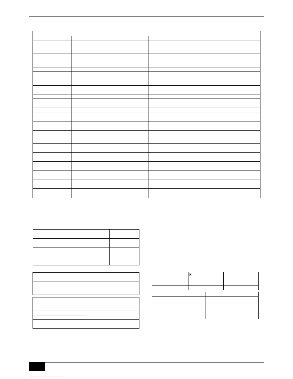
4. Технические характеристики
Модель
PUHY-P200YHM-A PUHY-P250YHM-A PUHY-P300YHM-A PUHY-P350YHM-A PUHY-P400YHM-A PUHY-P450YHM-A PUHY-P500YSHM-A PUHY-P550YSHM-A PUHY-P600YSHM-A PUHY-P650YSHM-A PUHY-P700YSHM-A
Уровень шумового давления (50/60 Гц)
56 дБ <A> 57 дБ <A> 59 дБ <A> 60 дБ <A> 61 дБ <A> 62 дБ <A> 60 дБ <A> 61 дБ <A> 62 дБ <A> 62,5 дБ <A> 63 дБ <A>
Уровень внешнего статического давления
0 Па *2
Внутренние
блоки
Суммарная емкость
50~130% *1
Модель
20~250
Количество
1~13 1~16 1~16 1~20 1~20 1~20 1~20 1~20 1~32 1~32 1~32
Диапазон
рабочих
температур
Стандартный тип
Режим охлаждения: – 5°C ~ 43°C (по сухому термометру)
Режим обогрева: – 20°C ~ 15,5°C (по смоченному термометру)
С внутренним
блоком
Режим охлаждения: 21°C ~ 43°C (по сухому термометру)
Режим обогрева: – 12,5°C ~ 20°C (по смоченному термометру)
Модель
PUHY-P750YSHM-A PUHY-P800YSHM-A PUHY-P850YSHM-A PUHY-P900YSHM-A PUHY-P950YSHM-A
PUHY-P1000YSHM-A PUHY-P1050YSHM-A PUHY-P1100YSHM-A PUHY-P1150YSHM-A PUHY-P1200YSHM-A PUHY-P1250YSHM-A
Уровень шумового давления (50/60 Гц)
63,5 дБ <A> 64 дБ <A> 64,5 дБ <A> 65 дБ <A> 64 дБ <A> 64,5 дБ <A> 65 дБ <A> 65 дБ <A> 65,5 дБ <A> 66 дБ <A> 66 дБ <A>
Уровень внешнего статического давления
0 Па *2
Внутренние
блоки
Суммарная емкость
50~130% *1
Модель
20~250
Количество
1~32 1~32 1~42 1~42 1~42 1~42 2~42 2~42 2~42 2~42 2~42
Диапазон
рабочих
температур
Стандартный тип
Режим охлаждения: – 5°C ~ 43°C (по сухому термометру)
Режим обогрева: – 20°C ~ 15,5°C (по смоченному термометру)
С внутренним
блоком
Режим охлаждения: 21°C ~ 43°C (по сухому термометру)
Режим обогрева: – 12,5°C ~ 20°C (по смоченному термометру)
Модель
PUHY-EP200YHM-A PUHY-EP300YHM-A PUHY-EP400YSHM-A PUHY-EP450YSHM-A PUHY-EP500YSHM-A PUHY-EP550YSHM-A PUHY-EP600YSHM-A PUHY-EP650YSHM-A PUHY-EP700YSHM-A
Уровень шумового давления (50/60 Гц)
57 дБ <A> 60 дБ <A> 60 дБ <A> 60 дБ <A> 62 дБ <A> 62 дБ <A> 63 дБ <A> 63 дБ <A> 63 дБ <A>
Уровень внешнего статического давления
0 Па *2
Внутренние
блоки
Суммарная емкость
50~130% *1
Модель
20~250
Количество
1~13 1~16 1~20 1~20 1~20 1~20 1~32 1~32 1~32
Диапазон
рабочих
температур
Стандартный тип
Режим охлаждения: – 5°C ~ 43°C (по сухому термометру)
Режим обогрева: – 20°C ~ 15,5°C (по смоченному термометру)
С внутренним
блоком
Режим охлаждения: 21°C ~ 43°C (по сухому термометру)
Режим обогрева: – 12,5°C ~ 20°C (по смоченному термометру)
Page 13

119
RU
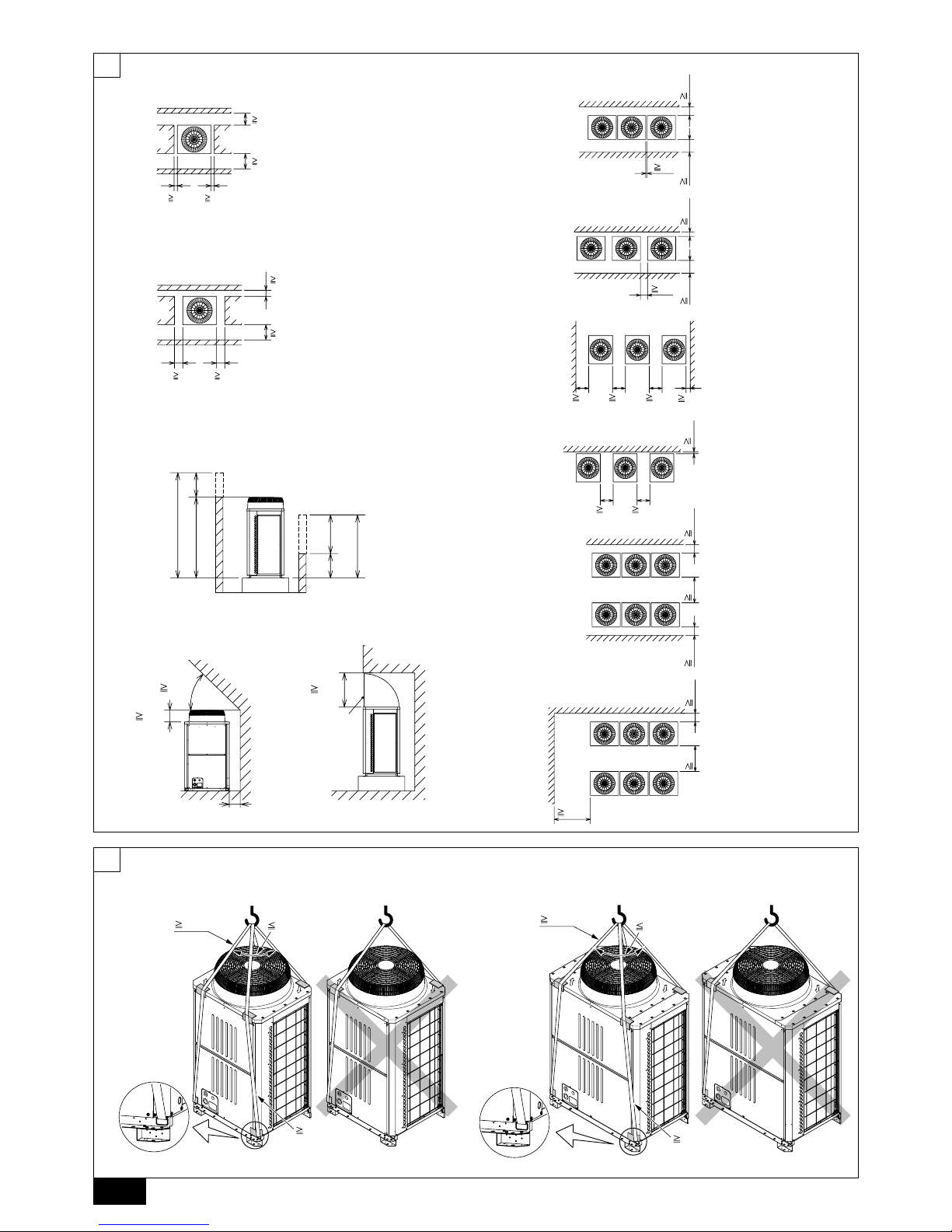
6. Требования к пространству вокруг блока
1 В случае установки одного блока
Предусмотрите вокруг блока достаточный объем свободного
пространства согласно требованиям, указанным в таблице на стр. 2.
[Fig. 6.0.1] (Стр. 2)
<A> Вид сверху <B> Вид сбоку
<C> В случае недостатка места до блокировки
A
Передняя часть
B
Высота блока
C
Задняя часть
D
Направляющая воздушного патрубка
(Устанавливается на месте)
(1)
Если расстояние от стены до задней части блока составляет 300 мм и более
(2)
Если расстояние от стены до задней части блока составляет 100 мм и более
(3) Если высота стены (H) спереди, сбоку или сзади превышает
установленные ограничения по высоте стены
Если высота стены <H> спереди, сбоку или сзади превышает
установленные ограничения по высоте стены, указанные ниже,
прибавьте расстояние, на которое превышено ограничение <h>, к
цифрам, отмеченным звездочкой.
•
•
<Ограничение по высоте стены> Спереди: До высоты блока
Снизу: До 500 мм от нижней части блока
Сбоку: До высоты блока
(4) Если в верхней части блока имеются помехи
2 В случае установки нескольких блоков
[Fig. 6.0.2] (Стр. 2)
A
Передняя часть
B
Должна быть открытой
C
Высота стены (H)
При установке нескольких блоков следует предусмотреть пространство,
обеспечивающее достаточную вентиляцию и оставляющее проходы, как
показано на стр. 2.
Блок должен быть открыт не менее, чем с двух сторон.
При установке одного блока следует прибавить расстояние, на
которое превышено ограничение по высоте стены <h>, к величинам,
отмеченным звездочкой.
•
•
•
[Fig. 7.0.1] (Стр. 2)
Используйте стропы, способные
выдержать вес изделия.
При переноске изделия должны использоваться 4-точечные стропы,
при этом следует оберегать изделие от ударов (Не используйте 2-
точечные стропы).
Для защиты изделия от повреждений в местах контакта со стропами
следует использовать защитные прокладки.
Угол строп должен составлять не более 40°.
Используйте 2 стропы длиной не менее 8 метров каждая.
•
•
•
•
•
Для защиты изделия от повреждения стропами расположите по его
углам защитные подложки.
Внимание:
При транспортировке/переноске изделия принимайте меры предосторожности.
- При установке наружного блока следует крепить изделие за
предусмотренные для этого места. Закрепите изделие в четырех точках
так, чтобы исключить его смещение. Крепление блока в трех точках
может привести к его смещению и последующему падению.
•
7. Способ поднимания
Модель
PUHY-EP750YSHM-A PUHY-EP800YSHM-A PUHY-EP850YSHM-A PUHY-EP900YSHM-A
Уровень шумового давления (50/60 Гц)
63 дБ <A> 64 дБ <A> 64 дБ <A> 65 дБ <A>
Уровень внешнего статического давления
0 Па *2
Внутренние
блоки
Суммарная емкость
50~130% *1
Модель
20~250
Количество
1~32 1~32 1~42 1~42
Диапазон
рабочих
температур
Стандартный тип
Режим охлаждения: – 5°C ~ 43°C (по смоченному термометру)
Режим обогрева: – 20°C ~ 15,5°C (по сухому термометру)
С внутренним
блоком
Режим охлаждения: 21°C ~ 43°C (по смоченному термометру)
Режим обогрева: – 12,5°C ~ 20°C (по сухому термометру)
*1: Совокупная эффективная емкость блоков составляет 130% и менее.
*2: Для обеспечения высокого статического давления на кондиционерах P350, P400, P450 и EP300 необходимо установить датчик-реле давления на главной
панели следующим образом.
SW3-9 : ON (ВКЛ), SW3-10 30 Па-совместимый: OFF (ВЫКЛ), 60 Па-совместимый: ON
Для обеспечения высокого статичного давления на кондиционерах (E)P200, P250 и P300 необходимо заменить электродвигатель на модели PAC-KBU05MT-F (продается отдельно).
5. Подтверждение комплектности
Данный блок включает в себя следующие части. Убедитесь в их наличии.
Информация по способам использования приведена в таблице 10.2.
1 Коленчатый патрубок
Внутренний диаметр ø19,05,
Внешний диаметр ø19,05
<для газовых магистралей>
2 Коленчатый патрубок
Внутренний диаметр ø25,4,
Внешний диаметр ø25,4
<для газовых магистралей>
3 Соединительная трубка
Внутренний диаметр ø12,7,
Внешний диаметр ø9,52
<для жидкостных магистралей>
4 Соединительная трубка
Внутренний диаметр ø15,88,
Внешний диаметр ø9,52
<для жидкостных магистралей>
5 Соединительная трубка
Внутренний диаметр ø15,88,
Внешний диаметр ø12,7
<для жидкостных
магистралей>
6 Соединительная трубка
Внутренний диаметр ø25,4,
Внешний диаметр ø19,05
<для газовых магистралей>
Модель P200 1 шт.–––––
EP200 – 1 шт.–––1 шт.
P250 – 1 шт.––––
P300 – 1 шт.1 шт.–––
EP300 – 1 шт.–1 шт.1 шт.–
P350 – 1 шт.– –1 шт.–
P400 – 1 шт.– –1 шт.–
P450 – 1 шт.––––
7 Соединительная трубка
Внутренний диаметр ø25,4,
Внешний диаметр ø22,2
<для газовых магистралей>
8 Соединительная трубка
Внутренний диаметр ø25,4,
Внешний диаметр ø28,58
<для газовых магистралей>
9 Соединительная трубка
Внутренний диаметр ø9,52,
Внешний диаметр ø9,52
<для жидкостных магистралей>
0 Соединительная трубка
Внутренний диаметр ø12,7,
Внешний диаметр ø12,7
<для жидкостных магистралей>
a Соединительная трубка
Внутренний диаметр ø15,88,
Внешний диаметр ø15,88
<для жидкостных магистралей>
Модель P200 – – 1 шт.– –
EP200 – – 1 шт.– –
P250 1 шт.–1 шт.– –
P300 1 шт.– –1 шт.–
EP300 1 шт.–––1 шт.
P350 – 1 шт.– –1 шт.
P400 – 1 шт.– –1 шт.
P450 – 1 шт.– –1 шт.
•
•
Page 14

120
RU
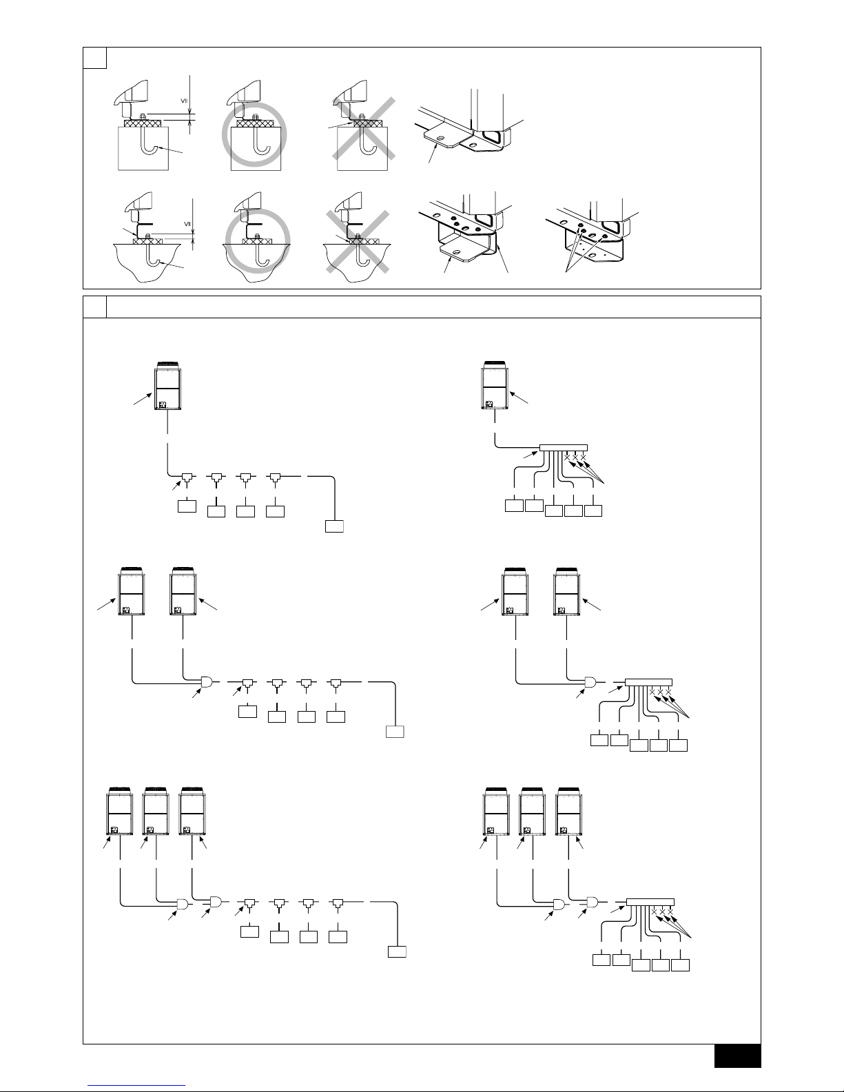
8.1. Установка
[Fig. 8.1.1] (Стр. 3)
<A> Без съемной ножки <B> Со съемной ножкой
A
M10 анкерный болт,
устанавливаемый на месте.
B
Угол не закреплен.
C
Крепежный кронштейн для анкеров
со вставным болтом (крепится
винтами в трех местах).
D
Съемная ножка
Надежно закрепите блок, чтобы исключить его падение под
воздействием землетрясения или сильного ветра.
В качестве основания для блока используется бетон либо угловой
кронштейн.
На монтажную часть могут передаваться вибрации, а в зависимости
от условий установки пол и стены могут генерировать вибрации
и шум. Поэтому следует обеспечить достаточную виброзащиту
(амортизирующая подушка,
амортизирующая рама и т.д).
Убедитесь в том, что углы надежно закреплены. В противном случае
может возникнуть деформация основания.
Длина выступающего торца анкерного болта не должна превышать 30 мм.
Анкеры со вставным болтом не могут быть использованы при установке
данного блока. Однако они могут быть использованы в случае, если в
четырех точках крепления установлены монтажные кронштейны.
•
•
•
•
•
•
[Fig. 8.1.2]
A
Винты
Съемная ножка может быть демонтирована на месте установки.
Демонтаж съемной ножки
Для демонтажа ножки ослабьте три винта (Два спереди и один сзади).
Если основание ножки при ее демонтаже было повреждено,
неисправность следует устранить на месте.
Предупреждение:
Место установки должно обладать прочностью, достаточной,
чтобы выдержать вес блока.
Недостаточная прочность может стать причиной падения блока и
нанесения им травм людям.
Обеспечьте при установке защиту от землетрясений и сильных ветров.
Недостаточная надежность установки может стать причиной
падения блока и нанесения им травм людям.
При изготовлении основания следует уделять внимание вопросам
прочности пола, дренирования воды <во время работы из блока вытекает
вода>, а также прокладке труб и электропроводки.
Меры предосторожности при прокладке труб и электропроводки под
блоком (Без съемной ножки)
При прокладке
труб и электропроводки под блоком под них необходимо
оставить достаточное место. Также необходимо убедиться в том, что высота
основания составляет не менее 100 мм для прокладки труб под блоком.
•
•
•
•
8. Установка блока
9. Установка трубопроводов
Труба, идущая от наружного блока, принимается распределителем и
разветвляется для соединения между внутренними блоками.
Способ подсоединения трубок следующий: соединитель с
колоколообразным расширением для внутренних блоков, газовые
и жидкостные трубки для наружных блоков, соединение спайкой.
Разветвленные секции запаяны.
Предупреждение:
При использовании открытого огня необходимо убедиться в
отсутствии утечки холодильного газа. При контактировании газа с
открытым пламенем газ разлагается, выделяя токсичные соединения,
способные вызвать серьезные отравления. Запрещается проводить
сварочные работы в непроветриваемом помещении. После завершения
монтажа соединений необходимо убедиться в отсутствии утечки газа.
Внимание:
Запрещается стравливать R410A в атмосферу.
Согласно Киотскому протоколу, R410A является
фреоносодержащим газом с потенциалом глобального потепления
(ПГП) = 1975.
9.1. Внимание
В данном изделии применяется хладагент R410A. При выборе
труб и шлангов следует руководствоваться требованиями местного
законодательства, касающегося используемых материалов и толщины
труб. (См. таблицу справа.)
1 Для трубок холодильного контура используйте следующие материалы.
Материал: Используйте бесшовные латунные трубки,
изготовленные из раскисленной фосфором меди. Кроме этого
убедитесь, что внутренняя и внешняя поверхность труб
чистая,
без частиц серы, окисей, пыли/грязи, частиц стружки, масел,
влаги или других загрязнений.
•
•
•
Размеры: Подробная информация по трубам холодильного
контура приведена в таблице 9.2.
2 Имеющиеся в продаже трубы нередко содержат различные
загрязнения. Продуйте их сухим инертным газом.
3 Примите меры, чтобы исключить во время установки попадание пыли,
воды и иных загрязнений в трубы.
4 Сведите к минимуму количество изгибающихся секций, радиус изгибов
делайте максимально
большим.
5 Для разветвлений используйте распределительные соединения,
продаваемые отдельно.
Размеры и толщина медных трубок и для модели R410A CITY MULTI.
Размер (мм)
Размер
(дюймов)
Радиальная толщина (мм) Тип трубки
ø6,35 ø1/4" 0,8 Круглая
ø9,52 ø3/8" 0,8 Круглая
ø12,7 ø1/2" 0,8 Круглая
ø15,88 ø5/8" 1,0 Круглая
ø19,05 ø3/4" 1,2 Круглая
ø19,05 ø3/4" 1,0 Тип 1/2H или H
ø22,2 ø7/8" 1,0 Тип 1/2H или H
ø25,4 ø1" 1,0 Тип 1/2H или H
ø28,58 ø1-1/8" 1,0 Тип 1/2H или H
ø31,75 ø1-1/4" 1,1 Тип 1/2H или H
ø34,93 ø1-3/8" 1,2 Тип 1/2H или H
ø41,28 ø1-5/8" 1,4 Тип 1/2H или H
* Тип
трубок размера ø19,05 (3/4") для кондиционера R410A вы можете
выбрать на свое усмотрение.
•
Внутренняя модель с комплектом разветвителя-двойника
Разветвитель трубы Коллектор
Модель блока с
нисходящим потоком
Общая длина менее
200
Модель блока с
нисходящим потоком
Общая длина более
201 и менее 400
Модель блока с
нисходящим потоком
Общая длина более
401 и менее 650
Модель блока с
нисходящим потоком
Общая длина более
651
4 разъема 8 разъемов 10 разъемов
CMY-Y102S-G2 CMY-Y102L-G2 CMY-Y202-G2 CMY-Y302-G2 CMY-Y104-G CMY-Y108-G CMY-Y1010-G
Двойник-разветвитель для наружного блока
Общая длина от
наружного блока
P500 ~ P650
EP400 ~ EP650
Общая длина от
наружного блока
P700 ~ P900
Общая длина от
наружного блока
P950 ~ P1250
EP700 ~ EP900
CMY-Y100VBK2 CMY-Y200VBK2 CMY-Y300VBK2
Page 15

121
RU
К наружному блоку
КРЫШКА
К наружному
блоку
10. Зарядка дополнительного количества хладагента
На сборочном предприятии система заполняется определенным
количеством хладагента.
Это количество не учитывает прокладку дополнительных трубок, поэтому
на месте монтажа необходимо дозаправить блок. Запишите длину всех
трубопроводов и количество добавленного хладагента. Это пригодится во
время проведения технического обслуживания блока.
10.1. Расчет необходимого количества
хладагента
Расчет необходимого количества хладагента производится исходя из
длины дополнительных труб и размера холодильного контура.
Для расчета воспользуйтесь таблицей, расположенной справа, после
чего заправьте систему.
•
•
Результаты расчета менее 0,1 кг округляются в большую сторону.
Например, 11,38 кг округляется до 11,4 кг.
<Дополнительная зарядка>
Дополнительная
зарядка
хладагентом
=
Размер трубок
для жидкости
Общая длина
ø19,05 × 0,29
+
Размер трубок
для жидкости
Общая длина
ø15,88 × 0,2
+
Размер трубок
для жидкости
Общая длина
ø12,7 × 0,12
(кг)(м) × 0,29 (кг/м)(м) × 0,2 (кг/м)(м) × 0,12 (кг/м)
+
Размер трубок
для жидкости
Общая длина
ø9,52 × 0,06
+
Размер трубок
для жидкости
Общая длина
ø6,35 × 0,024
+
α
(м) × 0,06 (кг/м)(м) × 0,024 (кг/м)
•
Запрещается использовать следующие инструменты,
применяемые с обычными видами хладагента.
(Штуцер манометра, заправочный шланг, течеискатель, обратный
клапан, заправочное основание, оборудование для сбора хладагента)
- Смешивание обычного хладагента и холодильного масла приведет к
ухудшению свойств масла.
- Попадание воды в систему приведет к ухудшению свойств масла.
- Хладагент R410A не содержит хлора. Поэтому течеискатели,
используемые для работы с обычными хладагентами, не применимы.
Обращайтесь с инструментами для R410A с особой осторожностью.
- Попадание в холодильный контур пыли, грязи или воды
может привести
к ухудшению эксплуатационных свойств холодильного масла.
Запрещается использовать существующие трубопроводы для нового блока.
-
Использование старых труб хладагента и старого масла охлаждения, содержащих
большие количества хлора, может привести к порче масла охлаждения нового блока.
Храните предназначенные для установки трубы в помещении,
герметически закрытыми с обоих концов до припайки.
-
Попадание в холодильный цикл пыли, грязи или воды может привести к ухудшению
эксплуатационных свойств холодильного масла и выходу компрессора из строя.
Запрещается использовать заправочные баллоны.
- Использование заправочного баллона может привести к ухудшению
эксплуатационных свойств хладагента.
Для мытья труб не используйте специальные моющие средства.
9.2. Установка трубопроводов хладагента
Пример соединения
[Fig. 9.2.1] (Стр.3, 4)
Модели с наружным блоком Тру бы для жидких хладагентов
Газовые трубы
Общая емкость внутренних блоков
Номер модели
Общая емкость для моделей с нисходящим потоком
Соединение
Певое разветвление кондиционеров P450 ~ P650
Певое разветвление кондиционеров P700, P750, P800
4-разъемный разветвитель (Общая емкость для моделей с нисходящим потоком 200)
8-разъемный разветвитель (Общая емкость для моделей с нисходящим потоком 400)
10-разъемный разветвитель (Общая емкость для моделей с нисходящим потоком 650)
Двойник-разветвитель для наружного блока
A
Наружный блок
B
Первое разветвление
C
Внутренний блок
D
Крышка
E
Двойник-разветвитель для наружного блока
*1 ø12,7 для более 90 м
*2 ø12,7 для более 40 м
*3 Размеры труб в колонках с A1 по A3 в данной таблице соответствуют размерам
моделей перечисленных в колонках 1,2 и 3 блока . При изменении порядка
моделей для блоков 1,2 и 3 используйте трубы надлежащего размера
.
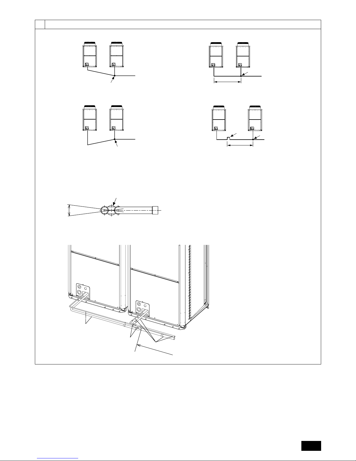
Меры предосторожности для комбинаций наружных блоков
См. [Fig. 9.2.2] по расположению двойников-разветвителей.
[Fig. 9.2.2] (Стр. 5)
<A> Разветвления должны спускаться вниз от разветвительной трубки к
наружному блоку (к разветвляющимся трубкам).
<B> Если длина труб, идущих с разветвлению от внешнего блока, превышает
два метра, необходимо предусмотреть ловушку через два метра (только для
газовых труб). Высота ловушки должна быть более 200 мм.
Отсутствие ловушки приведет к скоплению малса внутри трубы, приведя
к его
недостатку и повреждению компрессора.
<C> Ниспадание разветвлений
Угол разветвлений по отношению к земле должен составлять ±15°.
Превышение этого значения может привести к выходу блока из строя.
<D> Пример соединения труб
A
Ниспадание
B
Восхождение
C
Внутренний блок
D
Ловушка (только для газовых труб)
E
В предeлах 2 метров
F
Трубный двойник-разветвитель
G
Угол разветвлений по отношению
к земле должен составлять ±15°.
H
Труб ы на месте установкиIКомплект двойника-разветвителя
J
Прямой участок трубы длиной 500 мм и более
•
•
•
•
•
•
9 Недостаточное или избыточное количество хладагента в системе
приведет к аварийной остановке системы. Заправляйте строго
необходимое количество хладагента. При обслуживании справляйтесь
с записями относительно длины трубопроводов и количества
дополнительно заправленного хладагента, а также с таблицей
расчета, расположенной на задней стороне сервисной панели и
наклейками на всех внутренних блоках (
см. таблицу 9.2. для получения
дополнительной информаци по системе труб хладагента).
0 Заправляйте систему жидким хладагентом.
a Запрещается использовать хладагент для продувки системы. Для
вакуумирования системы используйте только вакуумный насос.
b
Обеспечивайте надежную изоляцию труб. Недостаточная изоляция снизит
рабочие характеристики и приведет к капанию конденсата и иным проблемам
(См. табл 10.4 по информации о термоизоляции труб хладагента).
c Подсоединение труб хладагента производится при закрытом клапане
наружного блока (заводская настройка), не открывайте клапан до
завершения монтажа труб между внутренним и наружным блоком и
проведения проверки на утечку и процедуры вакуумирования.
d Пайка труб производится неоксидными твердыми припоями.
В противном случае компрессор может выйти из строя. Пайка
производится с продувкой
азотом.
Не используйте средство против окисления, это может привести к
коррозии труб и ухудшению свойств холодильного масла.
При возникновении вопросов обращайтесь в компанию Мitsubishi
Electric.
(Информация по соединению труб и управлению клапаном приведена в
таблице 10.2.)
e Запрещается паять соединения наружного блока во время дождя.
Предупреждение:
При установке и переносе блока для зарядки системы используйте
только установленный тип хладагента.
- Смешивание различных типов хладагента приведет к нарушению
холодильного цикла и серьезным повреждениям.
Внимание:
Используйте вакуумный насос с обратным клапаном.
- Отсутствие у насоса клапана приведет к попаданию масла насоса в
холодильный цикл и последующему ухудшению свойств холодильного
масла.
•
6 Используйте специальные сочленения в случае, если диаметр трубки
хладагента отличается от диаметра распределительной трубки.
7 Соблюдайте ограничения по длине труб холодильного контура (длина,
разница высоты
и диаметр трубки) для исключения повреждения
оборудования или снижения характеристик охлаждения/обогрева.
8 После разветвления коллектора дополнительное разветвление не
устанавливается (соответствующие части отмечены с помощью
в
диаграмме ниже).
Page 16

122
RU
Условия
указаны
ниже:
Убедитесь в том, что труба хладагента не соприкасается с другими
трубами, панелями блока или пластинами основания.
Для пайки труб используйте неоксидный твердый припой.
<Примеры подсоединения труб хладагента>
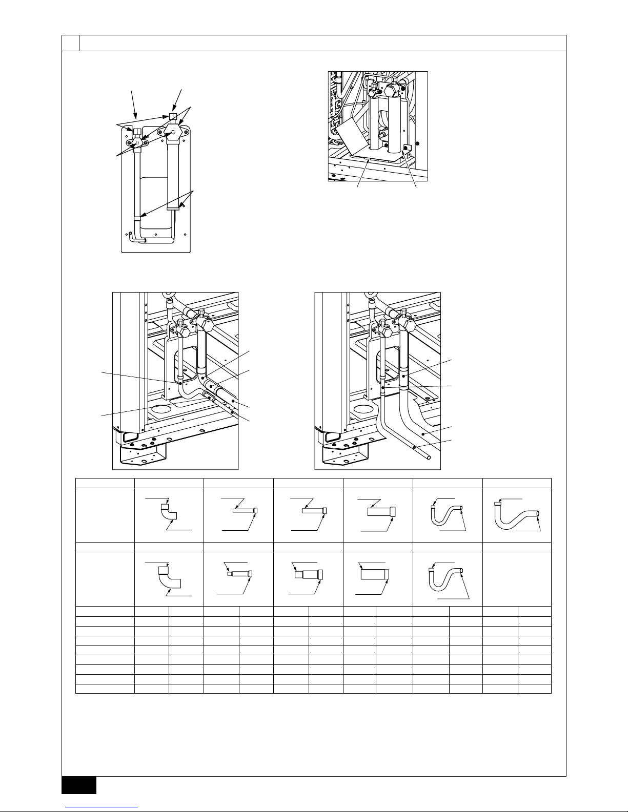
[Fig.10.2.2] (Стр. 6)
<A> Прокладка труб спереди <B> Прокладка труб снизу
<C> Прилагается к наружному блоку
A
Газо вая труба
(приобретается на месте)
B
Жидкостная труба
(приобретается на месте)
C
Форма
Прокладка труб спереди
1 Соединительное колено (Внутренний диаметр ø19,05, внешний диаметр
ø19,05) <Прилагается к наружному блоку>
2 Соединительное колено (Внутренний диаметр ø25,4, внешний диаметр
ø25,4) <Прилагается к наружному блоку>
3 Соединительная труба (Внутренний диаметр ø12,7, внешний диаметр
ø9,52) <Прилагается к наружному блоку>
4 Соединительная труба (Внутренний диаметр ø15,88 внешний диаметр
ø9,52) <Прилагается к наружному блоку>
5 Соединительная
труба (Внутренний диаметр ø15,88 внешний диаметр
ø12,7) <Прилагается к наружному блоку>
6 Соединительная труба (Внутренний диаметр ø25,4, внешний диаметр
ø19,05) <Прилагается к наружному блоку>
7 Соединительная труба (Внутренний диаметр ø25,4, внешний диаметр
ø22,2) <Прилагается к наружному блоку>
8 Соединительная труба (Внутренний диаметр ø25,4, внешний диаметр
ø28,58) <Прилагается к наружному блоку>
9 Соединительная труба (Внутренний диаметр ø9,52, внешний диаметр
ø9,52) <Прилагается к наружному блоку>
0 Соединительная труба (Внутренний диаметр ø12,7, внешний диаметр
ø12,7) <Прилагается к наружному блоку>
a Соединительная труба (Внутренний диаметр ø15,88 внешний диаметр
ø15,88) <Прилагается к наружному блоку>
Прокладка труб снизу
3 Соединительная труба (Внутренний диаметр ø12,7, внешний диаметр
ø9,52) <Прилагается к наружному блоку>
4 Соединительная труба (Внутренний диаметр ø15,88 внешний диаметр
ø9,52) <Прилагается
к наружному блоку>
5 Соединительная труба (Внутренний диаметр ø15,88 внешний диаметр
ø12,7) <Прилагается к наружному блоку>
*1 P200, P250, EP200: Развальцуйте жидкостную трубу (Внутренний
диаметр ø9,52) и установите ее непосредственно на клапан.
<приобретается на месте>
*2 P300: В случае использования в сочетании с другими наружными
блоками развальцуйте жидкостную трубу (Внутренний диаметр ø12,7) и
установите ее непосредственно на клапан. <приобретается
на месте>
*3 P450: Развальцуйте жидкостную трубу (Внутренний диаметр ø15,88) и
установите ее непосредственно на клапан. <приобретается на месте>
*4 P400: В случае использования в сочетании с другими наружными
блоками развальцуйте жидкостную трубу (Внутренний диаметр ø15,88)
и установите ее непосредственно на клапан. <приобретается на месте>
6 Соединительная труба (Внутренний диаметр ø25,4, внешний диаметр
ø19,05) <Прилагается к наружному
блоку>
7 Соединительная труба (Внутренний диаметр ø25,4, внешний диаметр
ø22,2) <Прилагается к наружному блоку>
8 Соединительная труба (Внутренний диаметр ø25,4, внешний диаметр
ø28,58) <Прилагается к наружному блоку>
*5 P200: Развальцуйте жидкостную трубу (Внутренний диаметр ø19,05) и
установите ее непосредственно на клапан. <приобретается на месте>
После вакуумирования и зарядки хладагентом полностью откройте ручку.
Эксплуатация блока с закрытым
клапаном приведет к образованию
избыточного давления в контурах высокого и низкого давления, что
выведет из строя компрессор, четырехсторонний клапан и т.п.
Воспользуйтесь приведенной формулой для определения добавочного
количества хладагента и подайте его в систему через сервисный
штуцер после окончания всех работ.
После окончания работ затяните сервисный штуцер для исключения
утечки газа. (Момент затяжки смотрите в таблице ниже.)
Рекомендованный момент затяжки:
Внешний диаметр
медной трубы (мм)
Крышка
(Нм)
Вал
(Нм)
Размер шестигранного
ключа (мм)
Сервисный
штуцер (Нм)
ø9,52 15 6 4
12
ø12,7 20 9 4
ø15,88 25 15 6
ø19,05 25 30 8
ø25,4 25 30 8
Внимание:
До окончания заправки добавочного количества хладагента на
месте установки клапан должен быть закрыт. Открывание клапана
до заправки блока может привести к выходу блока из строя.
Не добавляйте в хладагент индикатор утечки.
•
•
•
•
•
•
•
<Пример>
Внутренний блок
1: 125 A: ø12,7 40 м a: ø9,52 10 м
2: 100 B: ø9,52 10 м b: ø9,52 5 м
3: 40 C: ø9,52 15 м c: ø6,35 10 м
4: 32 D: ø9,52 10 м d: ø6,35 10 м
5: 63 e: ø9,52 10 м
Общая длина жидкостных труб следующая:
ø12,7: A = 40 = 40 м
ø9,52: B + C + D + a + b + e = 10 + 15 + 10 + 10 + 5 + 10 = 60 м
ø6,35: c + d = 10 + 10 = 20 м
Итого,
<Пример расчета>
Дополнительная зарядка хладагентом
= 40 × 0,12 + 60 × 0,06 + 20 × 0,024 + 2,5 = 11,4 кг
Значение α
Общая емкость соединений внутренних блоков
α
Модели ~ 80 2,0 кг
Модели 81 ~ 160 2,5 кг
Модели 161 ~ 330 3,0 кг
Модели 331 ~ 390 3,5 кг
Модели 391 ~ 480 4,5 кг
Модели 481 ~ 630 5,0 кг
Модели 631 ~ 710 6,0 кг
Модели 711 ~ 800 8,0 кг
Модели
801 ~ 890 9,0 кг
Модели 891 ~ 1070 10,0 кг
Модели 1071 ~ 1250 12,0 кг
Модели 1251 ~ 14,0 кг
10.2.
Меры предосторожности при
соединении труб и работе с клапанами
Все работы должны выполняться аккуратно и с принятием мер
предосторожности.
Демонтаж соединительной трубки
Во избежание утечки газа во время перевозки блока на клапан газового
и жидкостного хладагента устанавливается соединительная трубка.
Для демонтажа трубки выполните шаги от 1 до 3 перед тем как
подсоединять трубы хладагента к наружному блоку.
1 Убедитесь в
том, что сервисный клапан плотно закрыт (повернут по
часовой стрелке до упора).
2 Подсоедините зарядный шланг к сервисному штуцеру клапана и
удалите газ из трубы между сервисным клапаном и соединительной
трубкой (Момент затяжки 12 Нм).
3 После удаления газа нагрейте запаянную часть для демонтажа
соединительной трубки.
[Fig. 10.2.1] (Стр.6)
<A> [Клапан (жидкостной трубы/запаянного типа)]
<B> [Клапан (газовой трубы/запаянного типа)]
A
Сервисное отверстие
Для вакуумирования труб хладагента на месте.
(Момент затяжки 12 Нм)
B
Вал
Полностью закрыт при сборке, при соединении труб и при
вакуумировании. Полностью открывается после окончания всех работ.
<При открывании>
• Поверните вал против часовой стрелки с помощью шестигранного
ключа.
• Поверните вал до упора.
<При закрывании>
• Поверните вал по часовой стрелке с помощью шестигранного ключа.
• Поверните вал до упора.
C
Крышка
Снимите крышку перед работой с валом. По окончании работ
установите крышку на место.
D
Запаянная часть соединительной трубки
Предупреждение:
Данная часть трубки между сервисными клапанами заполнена
газом. Перед нагреванием запаянной части для ее демонтажа
необходимо удалить газ описанным выше способом.
- Невыполнение этого условия может привести к разрыву трубы при ее
нагреве и травмированию.
Внимание:
Перед нагреванием накройте сервисный клапан влажным полотенцем
вы избежание его нагрева выше 120˚C.
Во избежание нанесения ущерба не направляйте пламя на
проводку и металлические панели внутри блока.
Внимание:
Запрещается стравливать R410A в атмосферу.
Согласно Киотскому протоколу, R410A является фреоносодержащим
газом с потенциалом глобального потепления (ПГП) = 1975.
Подсоединение трубы хладагента
К данному изделию прилагаются соединительные трубы для передних
трубопроводов и нижних трубопроводов. (См. [Fig.10.2.2])
Перед подсоединением труб хладагента необходимо убедиться в
правильности размерности всех труб.
Размеры труб даны в пункте 9.2 раздела Установка трубопроводов хладагента.
•
•
•
•
•
•
•
•
Page 17

123
RU
[Fig. 10.2.3] (Стр.6)
A Пример изоляционных материалов (приобретаются на месте)
B Заполните промежуток на месте
Заделайте все отверстия, через которые проложены трубы и
электропроводка, чтобы исключить проникновения мелких животных и
дождевой воды и повреждение блока.
Внимание:
Заделайте все отверстия прокладки труб и проводки.
Проникновение мелких животных и воды может привести к выходу
блока из строя.
•
10.3.
Проверка на герметичность,
вакуумирование и зарядка хладагентом
1 Проверка на герметичность
Проводится при закрытом клапане наружного блока подачей давления через
предусмотренное для этого отверстие на клапане наружного блока. (Подача
давления производится в оба отверстия труб для газа и для жидкости.)
[Fig. 10.3.1] (Стр.7)
A
Азот
B
К наружному блокуCАнализатор системы
D
Рукоятка Low
E
Рукоятка Hi
F
Клапан
G
Труб ы для жидких хладагентов
H
Газовые трубы
I
Наружный блок
J
Сервисное отверстие
При проведении теста принимайте следующие меры предосторожности.
В случае с неазеотропным хладагентом (R410A), утечка газа приводит к
изменению состава соединений и ухудшается рабочие характеристики.
Поэтому при проведении теста следует принимать меры предосторожности.
Внимание:
Используйте только хладагент R410A.
- Использование других хладагентов, например, R22 или R407C,
содержащих хлор, приведет к ухудшению свойств холодильного масла и
неисправности компрессора.
2 Вакуумирование
Проводится с помощью вакуумного насоса при закрытом клапане
наружного блока подачей давления через предусмотренное для этого
отверстие на клапане наружного блока. (Вакуумирование производится
в оба отверстия труб для газа
и для жидкости.) После достижения
величины 650 Па (абс.) вакуумирование проводится еще не менее часа.
После этого останавливается вакуумный насос и система оставляется
на час. Убедитесь в том, что значение вакуума не увеличивается.
(Увеличение выше 130 Па может указывать на проникновение
воды в систему. Увеличьте давление для просушки азота до 0,05
МПа и
повторите вакуумирование.) По окончании герметизируйте
с помощью жидкого хладагента и отрегулируйте газовые трубы для
должного наполнения системы.
* Не используйте для продувки хладагент.
[Fig. 10.3.2] (Стр. 7)
A
Анализатор системыBРукоятка Low
C
Рукоятка Hi
D
Клапан
E
Труб ы для жидких
хладагентов
F
Газовые трубы
G
Сервисное
отверстие
H
Трехстороннее
соединение
I
Клапан
J
Клапан
K
Баллон R410A
L
Шкала
M
Вакуумный насос
N
К наружному блокуOНаружный блок
Примечание:
Добавляйте строго рассчитанное количество хладагента.
Заправляйте систему только жидким хладагентом.
Используйте специально предназначенные для блока штуцер
манометра, заправочный шланг и иные инструменты.
Используйте гравитометр. (Способный измерять до 0,1 кг.)
Используйте вакуумный насос с обратным клапаном.
(Рекомендованный вакуумный манометр: ROBINAIR 14830A
Thermistor Vacuum Gauge)
Также применяется вакуумный манометр, выдающий 65 Па (абс.)
после 5 минут работы.
3 Заправка
хладагента
Поскольку применяемый хладагент неазеотропичен, его необходимо
заправлять в жидком состоянии. При зарядке с помощью баллона, если
баллон не имеет сифонной трубки, для заправки следует перевернуть
•
•
•
•
баллон, как показано в Fig. 10.3.3. Если баллон снабжен такой трубкой (см.
рисунок справа), то заправку можно вести, держа баллон вертикально.
Поэтому следует обращать внимание
на характеристики баллона. Если
блок заправляется газовым хладагентом, необходимо заменить весь
хладагент на новый. Не используйте хладагент, оставшийся в баллоне.
[Fig. 10.3.3] (Стр. 7)
A
Сифонная трубкаBВ случае с R410A баллон не имеет сифонной трубки.
10.4. Термоизоляция труб хладагента
В обязательном порядке снабдите трубы хладагента изоляцией (раздельно
газовые и жидкостные) достаточным количеством термостойкого
полиэтилена таким образом, чтобы отсутствовали зазоры между
внутренним блоком и изоляцией, а также между самими изоляционными
материалами. Недостаточная изоляция может привести к капанию
конденсата. Особое внимание уделите изоляции потолочной области.
[Fig. 10.4.1] (Стр.7)
A
Стальная проволока
B
Трубопроводы
C
Битумная мастика или битум
D
Термоизоляционный материал А
E
Внешнее покрытие В
Термоизоляционный
материал А
Стекловолокно + Стальная проволока
Клеящий материал + Теплостойкая полиэтиленовая пена
+ Клейкая лента
Внешнее
покрытие В
Внутренний
блок
Пластиковая лента
Пол вокруг
блока
Водонепроницаемый брезент +
Бронзосодерщащий битум
Наружный
блок
Водонепроницаемый брезент + Цинковая
пластина + Масляная краска
Примечание:
Использование полиэтилена в качестве покрытия делает
ненужным применение битума.
Термоизоляция на проводах питания не используется.
[Fig. 10.4.2] (Стр. 7)
A
Труб ы для жидких хладагентов
B
Газовые трубы
C
Электрический провод
D
Отделочная лента
E
Изолятор
[Fig. 10.4.3] (Стр. 7)
•
•
Порядок проведения теста на герметичность Ограничение
1. Подача азота под давлением
(1) После достижения рабочего давления (4,15 МПа) азота оставьте систему в таком
состоянии на сутки. Если за сутки давление не упадет, система герметична.
Ели давление упадет, может возникнуть необходимость проведения пробы на
образование пузырей, поскольку место утечки неизвестно.
(2)
После описанного выше процесса нагнетания давления нанесите на спаянные соединения,
вальцованные соединения и т.п. течеискатель (Kyubofl ex, и т.п.) и осмотрите систему.
(3) После окончания теста вытрите средство.
Использование при тесте на герметичность в качестве рабочего
вещества воздуха (кислорода) или огнеопасного газа может
привести к возгоранию или взрыву.
•
2. Нагнетание давления с помощью азота и холодильного газа
(1) Доведя давления газа приблизительно до 0,2 МПа, доведите давление в системе
до расчетного значения (4,15 МПа).
Не выполняйте
эти операции одновременно. Остановите нагнетание и убедитесь
в том, что давление не падает.
(2) Протестируйте систему на наличие утечек, используя совместимый R410A
электрический течеискатель.
(3) Этот тест можно проводить вместе с пробой на пузыри.
Не используйте хладагент, отличный от рекомендованного к
использованию в системе.
Герметизация газом из баллона приведет к изменению состава
хладагента
в цилиндре.
Используйте манометр, зарядный шланг и другие инструменты,
специально предназначенные для использования с R410A.
Течеискатель, предназначенный для R22, не способен
определить утечку R410A.
Не используйте галоидный течеискатель. (Он не пригоден для
поиска утечки в данном случае.)
•
•
•
•
•
Page 18

124
RU
11.1. Внимание
1 Строго соблюдайте все требования и стандарты государственных
организаций, касающиеся электрооборудования, проведения
электротехнических работ и предписания электрических компаний.
2 Электропроводка пультов управления (далее именуемая как линия
передачи данных) должна находиться на расстоянии не менее 5 см от
провода питания, чтобы исключить возникновение помех (не используйте
для линии передачи сигнала и провода питания
единую изоляцию).
3 В обязательном прядке заземлите наружный блок надлежащим образом.
4 Проводка блока подключения должна иметь запас по длине, поскольку
при проведении технического обслуживания иногда возникает
необходимость ее перемещения.
5 Запрещается подключать провод питания к блоку выводов линии передачи
данных. Это приведет к выходу из строя электрических компонентов.
6
Для линии передачи сигнала используется двужильный экранированный
кабель. Подключение линий передачи данных с помощью единого
мультиплексного кабеля приведет к сбоям в работе системы вследствие
взаимовлияния сигналов.
7 К блоку выводов наружного блока должна подключаться исключительно
указанная линия передачи данных.
Неправильное подсоединение вызовет неисправность системы.
8 В случае подключения ведущего пульта
управления или комплексного
подключения различных систем кондиционеров необходимо подключить
линию передачи данных между наружными блоками различных систем
кондиционеров.
Данная линия подключается между блоками выводов центральных
пультов (двужильный провод без соблюдения полярности).
9 Группа создается автоматически пультом дистанционного управления.
11.2. Панель управления и места
подсоединения проводки
1 Наружный блок
1. Снимите переднюю панель блока управления, открутив четыре винта и
слегка нажав на нее сверху. Вытяните панель.
2. Подсоедините линию передачи данных “внутренний блок - наружный
блок ” к блоку выводов (ТВ3) линии передачи данных “внутренний блок
- наружный блок”.
Если наружные блоки составляют единую систему, последовательно
подключите их выводы TB3 (M1, M2,
). Подсоедините линию
передачи данных “внутренний блок - наружный блок” для наружных
блоков к выводу TB3 (M1, M2,
) одного из наружных блоков.
3. Подсоедините линии передачи данных центрального пульта (между
центральным пультом и наружным блоком другой системы) к блоку
выводов центрального пульта (TB7). Если наружные блоки составляют
единую систему, последовательно подключите их выводы TB7 (M1, M2, S).
(*1)
*1: Если ТВ7 наружного блока единой системы не подключен
последовательно, подсоедините линию передачи сигнала
центрального пульта к TB7
на OC (*2). Если OC неисправен
или центральный пульт подключался в момент отключения
электричества, подсоедините последовательно TB7 на OC, OS1
и OS2 (В случае если наружный блок, провод питания CN41
которого на пульте управления был заменен на CN40, неисправен
или отсутствует питание, централизованное управление не будет
выполняться, даже если TB7 подключен последовательно).
*2 OC, OS1 и OS2 наружных блоков в единой системе определяются
автоматически.
Они определяются как OC, OS1 и OS2 в порядке
убывания емкости (Если емкость одинакова, порядок будет
устанавливаться в порядке уменьшения номеров).
4. В случае с линией передачи сигнала “внутренний - внешний”
необходимо подсоединить провод заземления к выводу заземления
(
). В случае с линией передачи сигнала центрального пульта
необходимо подсоединить провод заземления к выводу экрана (S) на
блоке выводов центрального пульта (TB7). В случае с наружными
блоками, у которых штепсель питания CN41 заменен на CN40,
напрямую подсоедините вывод экрана (S) к клемме заземления (
) в
дополнение к указанному выше.
5. Надежно закрепите подсоединенные провода в нижней части блока
вывода с помощью фиксаторов. Физическое воздействие, приложенное
к блоку выводов, может привести к короткому замыканию, нарушению
заземления либо возгоранию.
[Fig. 11.2.1] (Стр. 8)
A
Источник питания
B
Линия передачи
C
Винт заземления
[Fig. 11.2.2] (Стр. 8)
A
Лямка кабеля
B
Повод питания
C
Линия передачи
2 Установка изоляционной трубы
Сделайте отверстия для прокладки изоляционной трубы в основании и
нижней части передней панели.
При проведении изоляционной трубы через проделанные отверстия следует
удалить заусеницы и защитить трубу с помощью изоляционной ленты.
Закройте отверстие изоляционной трубой для исключения
проникновения в блок мелких животных.
11.3.
Подсоединение кабелей передачи данных
1 Типы кабелей передачи данных
1. Подсоединение кабелей передачи данных
Типы кабелей передачи данных: Экранированный кабель CVVS, CPEVS
или MVVS
Диаметр кабеля: Более 1,25 мм
2
Максимальная длины проводки: До 200 метров
Максимальная длина линий передачи данных центрального пульта и
наружных/внутренних блоков (Максимальная длина через наружные
блоки): Максимум 500 м
Максимальная длина проводки между блоком питания линий передачи
данных (центрального пульта), всех наружных блоков и центрального
пульта системы составляет 200 метров.
2. Кабели пульта дистанционного управления
Контроллер дистанционного управления M-NET
Тип кабеля
Изолированный двужильный кабель
(неэкранированный) CVV
Диаметр кабеля От 0,3 до 1,25 мм
2
(От 0,75 до 1,25 мм2)*
Заметки
Если длина превышает 10 метров, используйте
кабель с теми же характеристиками, что и 1.
Подключение кабелей передачи данных.
Пульт дистанционного управления МА
Тип кабеля
Изолированный двужильный кабель (неэкранированный) CVV
Диаметр кабеля От 0,3 до 1,25 мм2 (От 0,75 до 1,25 мм2)*
Заметки До 200 метров
* Соединенный с простым пультом дистанционного управления.
•
•
•
•
•
•
•
•
•
11.
Проводка (Для получения информации см. руководство по установке каждого блока и пульта управления.)
Отверстия
При заполнении полсти цементным раствором закройте отверстие
металлической пластиной, чтобы исключить попадание изоляционного
материала внутрь. В данной части негорючие материалы должны применяться
как для изоляции, так и для покрытия. (Не используйте виниловое покрытие.)
Изоляционные материалы, приобретаемые на месте, должны отвечать
следующим требованиям:
Размер трубы
ø6,35 - 25,4 мм ø28,58 - 41,28 мм
Толщина Мин. 10 мм Мин. 15 мм
Термостойкость Мин. 100°C
* Установка
труб в местах, подверженных воздействию высоких температур
и влажности, например, на верхних этажах зданий, может потребовать
применения материалов большей толщины, чем указано выше.
* Если клиент выдвигает особые требования, убедитесь в том, что они
отвечают требованиям, перечисленным выше.
•
[Fig. 10.4.4] (Стр. 7)
<A> Внутренняя стена (скрытое) <B> Внешняя стена
<C> Внешняя стена (открытое) <D> Пол (водозащита)
<E> Вал трубы на крыше
<F> Отверстия в зоне повышенной пожароопасности и граничащей стене
A
Хомут
B
Теплоизоляционный материал
C
Изоляция
D
Уплотнительный материал
E
Ремень
F
Водонепроницаемый слой
G
Хомут с фаской
H
Изоляционный материал
I
Цементный раствор или иной негорючий материал
J
Несгораемый теплоизоляционный материал
Page 19

125
RU
2 Примеры электропроводки
Название блока управления, символ и допустимое количество пультов управления.
Название Код Допустимое количество соединений
Наружный блок
Основной блок OC – (*2)
Подчиненный блок OS1, OS2 – (*2)
Внутренний блок Пульт управления внутреннего блока IC От 1 до 32 блоков на 1 OC (*1)
Пульт дистанционного управления Пульт дистанционного управления (*1) RC Максимум 2 блока на группу
Другие Усилитель сигнала RP От 0 до 1 блока на 1 OC (*1)
*1 В зависимости от количества подсоединенных внутренних блоков может понадобиться усилитель сигнала (RP).
*2 OC, OS1 и OS2 внутренних блоков в единой системе определяются
автоматически. Они определяются как OC, OS1 и OS2 в порядке уменьшения емкости.
(Если емкость одинакова, порядок будет устанавливаться в порядке уменьшения номеров.)
Пример комплексной системы с несколькими наружными блоками (Необходимо экранирование
проводки и назначение адресов.)
<Примеры прокладки провода передачи данных>
[Fig. 11.3.1] Пульт дистанционного управления M-NET (Стр.8)
*1: При неподсоединенном к линии передачи данных блоке обеспечения питания,отсоедините штепсель (CN41) одного наружного блока и подсоедините
его к CN40.
*2: Если используется пульт системы, переведите выключатель SW2-1 на всех наружных блоках в положение ON.
[Fig. 11.3.2] Пульт дистанционного управления MA (Стр. 9)
<A> Переключите штепсель с CN41 на CN40
<B> Выключатель SW2-1: ON
<C> Оставьте штепсель на CN41
A
Группа 1
B
Группа 3
C
Группа 5
D
Экранированный провод
E
Пульт дистанционного управления подчиненного блока
( ) Адрес
[Fig. 11.3.3] Сочетание наружных блоков и усилителя сигнала (Стр. 9)
<Способ подключения и Назначение адресов>
a. При создании подсоединения между наружным блоком (ОС) и внутренним блоком (IC), а также для всех соединений OC-OC, OC-OS, OS-OS и IC-IC
необходимо в обязательном порядке использовать экранированный провод.
b. Для соединения выводов M1 и M2, а также клеммы заземления всех наружных блоков (OC) к выводам М
1, М2 и S на блоке передачи сигнала внутреннего
блока (IC) используйте провод питания
на блоке передачи сигнала (TB3). Для OC и OS, подсоедините TB3 к TB3.
c. Подсоедините выводы 1 (M1) и 2 (M2) на блоке выводов провода передачи данных внутреннего блока (IC) с последним адресом с такой же группой блока
выводов пульта дистанционного управления (RC).
d. Подсоедините выводы M1, M2 и S на блоке выводов центрального пульта управления (TB7) к наружному блоку другого комплекса кондиционеров (OC).
Для OC и OS единого комплекса подсоедините TB7 к TB7.
e. Если блок питания не установлен на линии передачи сигнала центрального пульта управления, переключите штепсель панели управления с CN41 к CN40
только одного наружного блока системы.
f. Подсоедините вывод S блока выводов центрального пульта (TB7) наружного блока (OC) к блоку, к которому в CN40 был подключен штепсель, к клемме
заземления в клеммной коробке.
g. Включите кнопку назначения адресов следующим образом.
* Для назначения наружному блоку адреса 100, кнопка назначения адреса должна быть установлена на 50.
Блок Диапазон Метод установки
Внутренний блок (Основной) От 01 до 50 Используйте самый последний адрес в одной группе внутренних блоков
Внутренний блок (Подчиненный) От 01 до 50
Используйте адрес, отличный от адреса IC (Основной), из блоков
одной группы внутренних
блоков. Адрес должен быть следующим после IC (Основной)
Наружный блок (OC, OS) От 51 до 100
Назначьте наружным блокам единой системы кондиционеров порядковые номера. OC, OS1 и
OS2 идентифицируются автоматически. (*1)
M-NET R/C (Основной) От 101 до 150 Используйте адрес IC (Основной) той же группы, прибавив к нему 100
M-NET R/C (Подчиненный) От 151 до 200 Используйте адрес IC (Основной) той же группы, прибавив к нему 150
MA R/C – Назначение адреса не нужно (Адрес назначается основным и подчиненным пультам)
h. Настройку работы комплекса внутренних блоков выполняет пульт дистанционного управления (RС) после подачи питания.
i. При подключении центрального пульта дистанционного управления к системе необходимо перевести все выключатели (SW2-1) панелей управления всех
наружных блоков (OC, OS) в положение “ON” (ВКЛ).
*1 OC, OS1 и OS2 внутренних блоков в единой системе
определяются автоматически. Они определяются как OC, OS1 и OS2 в порядке убывания емкости
(Если емкость одинакова порядок будет устанавливаться в порядке уменьшения номеров).
<Допустимая длина>
1 Пульт дистанционного управления M-NET
Максимальная длина через наружные блоки: L1+L2+L3+L4 и L1+L2+L3+L5 и L1+L2+L6 500 м (1,25 мм2 и более)
Максимальная длина провода передачи данных: L
1 и L3+L4 и L3+L5 и L6 и L2+L6 200 м (1,25 мм
2
и более)
Длина кабеля пульта дистанционного управления:
1, 2, 3, 4 10 м (от 0,3 до 1,25 мм
2
)
Если длина превышает 10 метров, воспользуйтесь экранированным проводом диаметром 1,25 мм
2
.
Длина данного участка (L
8) при расчете максимальной длины и общей длины должна учитываться.
2 Пульт дистанционного управления MА
Максимальная длина через наружный блок (кабель M-NET): L1+L2+L3+L4 и L1+L2+L6 500 м (1,25 мм2 и более)
Максимальная длина кабеля передачи данных (кабель M-NET): L1 и L3+L4 и L6 и L2+L6 200 м (1,25 мм2 и более)
Длина кабеля пульта дистанционного управления: m
1+m2 и m1+m2+m3+m4 200 м (от 0,3 до 1,25 мм
2
)
3 Усилитель сигнала
Максимальная длина кабеля передачи данных (кабель M-NET): 1 L
1+L2+L3+L5+L6 200 м (1,25 мм
2
)
2 L
1+L2+L3+L5+L7 200 м (1,25 мм
2
)
3 L
1+L2+L4 200 м (1,25 мм
2
)
4 L
6+L5+L3+L4, L4+L3+L5+L7 200 м (1,25 мм
2
)
•
•
•
•
•
•
•
•
Page 20

126
RU
Длина кабеля пульта дистанционного управления: 1, 2 10 м (0,3 - 1,25 мм2)
Если длина превышает 10 м, используйте экранированный кабель диаметром 1,25 мм
2
и измерьте
длину этого участка (L
4 и L7) в рамках измерения общей длины и максимальной длины.
11.4. Подсоединение основной проводки питания и характеристики оборудования
Схема электропроводки (Пример)
[Fig. 11.4.1] (Стр. 9)
A
Выключатель (выключатели проводки и утечки тока)
B
Реле контроля утечки тока
C
Наружный блок
D
Распаячная коробка
E
Внутренний блок
Толщина провода питания, характеристики выключателей и сопротивление системы
Модель
Минимальная толщина провода (мм
2
)
Реле контроля утечки
тока
Локальное реле (А)
Реле проводки
(NFB) (A)
Максимально
допустимое
сопротивление
системы
Основной
кабель
Распределитель
Заземление
Мощность
Плавкий
предохранитель
Наружный
блок
PUHY-(E)P200YHM
4,0 - 4,0
30 А 100 мA 0,1с и менее
25 25 30 *1
PUHY-P250YHM
4,0 - 4,0
30 А 100 мA 0,1с и менее
32 32 30 *1
PUHY-(E)P300YHM
4,0 - 4,0
30 А 100 мA 0,1с и менее
32 32 30 *1
PUHY-P350YHM
6,0 - 6,0
40 А 100 мA 0,1с и менее
40 40 40 0,24 Ω
PUHY-P400YHM
10,0 - 10,0
60 А 100 мA 0,1с и менее
63 63 60 0,24 Ω
PUHY-P450YHM
10,0 - 10,0
60 А 100 мA 0,1с и менее
63 63 60 0,19 Ω
Рабочий ток
внутреннего
блока
16 A и менее
1,5 1,5 1,5
20 А 30 мA 0,1с и менее
16 16 20
(соотв.
IEC61000-3-3)
25 A и менее
2,5 2,5 2,5
30 А 30 мA 0,1с и менее
25 25 30
(соотв.
IEC61000-3-3)
32 A и менее
4,0 4,0 4,0
40 А 30 мA 0,1с и менее
32 32 40
(соотв.
IEC61000-3-3)
*1: Отвечает стандарту IEC61000-3-3
1. Используйте раздельное питание для внешнего и внутреннего блоков. Убедитесь в том, что OC и OS снабжены раздельной проводкой.
2. Учитывайте внешние факторы (температура наружного воздуха, наличие прямого солнечного света, дождевая вода) при выполнении проводки
и соединений.
3. Приведенный размер провода отражает минимальное значение для проводки в металлической изоляции.
При падении напряжения следует
использовать провод на один размер толще в диаметре.
Убедитесь, что падение напряжения не превышает 10%.
4. В некоторых регионах могут быть специальные требования к проводке.
5. Провода питания устройств, предназначенных для использования вне помещений, не должны быть легче гибкого провода с
полихлоропреновой изоляцией (тип 245 IEC57). Например, используйте провод YZW.
6. Установщик
кондиционера должен использовать реле, расстояние между контактами которого должно составлять не менее 3 мм.
Предупреждение:
Используйте рекомендованные типы проводов и не подвергайте выводы проводов воздействию внешних сил. Ненадежное подсоединение
может стать причиной перегрева или возгорания.
Используйте реле защиты от скачков напряжения надлежащего типа. Помните, что при перегрузке напряжения может присутствовать и
постоянный ток.
Внимание:
В некоторых случаях может потребоваться установка на инвертере реле контроля утечки на землю. Если такое реле не установлено, существует
опасность поражения электрическим током.
Используйте реле и плавкие предохранители рекомендованного номинального тока. Использование реле и предохранителей большего
номинального тока может привести к выходу изделия из строя или возгоранию.
Примечание:
Данное изделие подлежит
подключению к электросети, сопротивление которой на блоке питания не превышает значения, указанного в таблице
выше.
Пользователь обязан проследить за выполнением данного условия.
При необходимости пользователь обязан запросить данные по сопротивлению у компании-поставщика электроэнергии.
Данное оборудованием соответствует стандарту IEC 61000-3-12 при условии, что мощность при коротком замыкании S
SC
выше или равна SSC
(*2) на стыковочном устройстве между изделием и электросетью. Ответственность по обеспечению соответствия электропитания данным
требованиям (мощность короткого замыкания S
SC
выше или равна SSC (*2)) лежит на пользователе (при необходимости пользователь обязан
проконсультироваться со специалистами компании-поставщика электроэнергии).
S
SC
(*2)
Модель S
SC
(MVA)
PUHY-(E)P200YHM 1,14
PUHY-P250YHM 1,27
PUHY-(E)P300YHM 1,57
PUHY-P350YHM 2,24
PUHY-P400YHM 2,28
PUHY-P450YHM 2,80
•
•
•
•
•
•
•
•
Page 21

127
RU
12. Тестовый запуск
12.1. Следующие явления не являются признаками неисправностей.
Явление
Дисплей пульта дистанционного
управления
Причина
Внутренний блок не охлаждает (не
обогревает).
Мигает сообщение
“Охлаждение (обогрев)”
Если какой-либо другой внутренний блок работает в режиме обогрев (охлаждение),
то работа другого блока в режиме охлаждение (обогрев) невозможна.
Автоматические жалюзи пришли в
движение и начинают подавать воздух
горизонтально.
Обычный дисплей Если в течение часа воздух подавался вниз, то блок может автоматически
перейти к подаче воздуха вниз. Во время или сразу после обогрева
автоматические жалюзи поворачиваются и в течение короткого периода
подают воздух в горизонтальном направлении.
Настройки вентилятора во время
обогрева изменяются.
Обычный дисплей
При выключении термостата система начинает работать на минимальной скорости.
Прежний режим будет восстановлен автоматически при включении термостата.
В режиме обогрева останавливается
вентилятор.
Режим отопления Вентилятор останавливается в данном режиме.
Вентилятор не останавливается после
выключения.
Отсутствует подсветка Вентилятор запрограммирован работать в течение минуты для
выдувания остатков тепла (только в режиме обогрева).
Не задан режим работы вентилятора при
включении питания.
прогрев После включения кондиционера работа на минимальной скорости в
течение 5 минут
или до тех пор, пока трубы не прогреются до 35°C, после
этого работы на низкой скорости в течение 2 минут, затем включается
заданный режим (Регулировка обогрева).
Пульт дистанционного управления
внутреннего блока отображает индикатор
“H0” или “PLEASE WAIT” в течение пяти
минут после включения питания.
Мигает “H0” или “PLEASE
WAIT”
Система находится в процессе запуска.
Воспользуйтесь пультом после того
, как индикаторы “H0” или “PLEASE
WAIT” погаснут.
Дренажный насос не останавливается
после выключения блока.
Гаснет После выключения режима охлаждения дренажный насос работает еще
три минуты.
Дренажный насос продолжает работать
на выключенном блоке.
Блок включает насос в случае, если необходимо дренировать воду, даже
если блок остановлен.
При переключении из режима обогрева в режим
охлаждения и наоборот блок издает звуки.
Обычный дисплей Это звук переключения контура охлаждения, он не является признаком
неисправности.
Сразу после запуска внутренний блок
издает звуки перетекающего хладагента.
Обычный дисплей Звук исходит от нестабилизировавшегося потока хладагента. Это
временное явление, не являющееся неисправностью.
Теплый воздух выходит из блока, который
не работает в режиме обогрева.
Обычный дисплей
Это происходит вследствие открывания клапана LEV внутреннего блока для
предотвращения сжижения хладагента. Это не является неисправностью.
13. Информация на табличке параметров
Модель P200 P250 P300 P350 P400 P450
Сочетание блоков -----Хладагент (R410A) 6,5 кг 9,0 кг 9,0 кг 11,5 кг 11,5 кг 11,5 кг
Допустимое давление (Па) Высокое давление: 4,15 МПа, Низкое давление: 2,21 МПа
Масса без упаковки 185 кг 200 кг 215 кг 245 кг 245 кг 245 кг
Модель P500 P550 P600
Сочетание блоков P250 P250 P300 P250 P350 P250
Хладагент (R410A) 9,0 кг 9,0 кг 9,0 кг 9,0 кг 11,5 кг 9,0 кг
Допустимое давление (Па) Высокое давление: 4,15 МПа, Низкое давление: 2,21 МПа
Масса без упаковки 200 кг 200 кг 215 кг 200 кг 245 кг 200 кг
Модель P650 P700 P750
Сочетание блоков P350 P300 P350 P350 P400 P350
Хладагент (R410A) 11,5 кг 9,0 кг 11,5 кг 11,5 кг 11,5 кг 11,5 кг
Допустимое давление (Па) Высокое давление: 4,15 МПа, Низкое давление: 2,21 МПа
Масса без упаковки 245 кг 215 кг 245 кг 245 кг 245 кг 245 кг
Модель P800 P850 P900
Сочетание блоков P450 P350 P450 P400 P450 P450
Хладагент (R410A) 11,5 кг 11,5 кг 11,5 кг 11,5 кг 11,5 кг 11,5 кг
Допустимое давление (Па) Высокое давление: 4,15 МПа, Низкое давление: 2,21 МПа
Масса без упаковки 245 кг 245 кг 245 кг 245 кг 245 кг 245 кг
Модель P950 P1000
Сочетание блоков P400 P300 P250 P400 P300 P300
Хладагент (R410A) 11,5 кг 9,0 кг 9,0 кг 11,5 кг 9,0 кг 9,0 кг
Допустимое давление (Па) Высокое давление: 4,15 МПа, Низкое давление: 2,21 МПа
Масса без упаковки 245 кг 215 кг 200 кг 245 кг 215 кг 215 кг
Модель P1050 P1100
Сочетание блоков P400 P350 P300 P400 P350 P350
Хладагент (R410A) 11,5 кг 11,5 кг 9,0 кг 11,5 кг 11,5 кг 11,5 кг
Допустимое давление (Па) Высокое давление: 4,15 МПа, Низкое давление: 2,21 МПа
Масса без упаковки 245 кг 245 кг 215 кг 245 кг 245 кг 245 кг
Модель P1150 P1200
Сочетание блоков P450 P350 P350 P450 P400 P350
Хладагент (R410A) 11,5 кг 11,5 кг 11,5 кг 11,5 кг 11,5 кг 11,5 кг
Допустимое давление (Па) Высокое давление: 4,15 МПа, Низкое давление: 2,21 МПа
Масса без упаковки 245 кг 245 кг 245 кг 245
кг 245 кг 245 кг
Page 22

128
RU
Модель P1250
Сочетание блоков P450 P450 P350
Хладагент (R410A) 11,5 кг 11,5 кг 11,5 кг
Допустимое давление (Па) Высокое давление: 4,15 МПа, Низкое давление: 2,21 МПа
Масса без упаковки 245 кг 245 кг 245 кг
Модель EP200 EP300 EP400 EP450
Сочетание блоков - - EP200 EP200 P250 EP200
Хладагент (R410A) 9,0 кг 11,5 кг 9,0 кг 9,0 кг 9,0 кг 9,0 кг
Допустимое давление (Па) Высокое давление: 4,15 МПа, Низкое давление: 2,21 МПа
Масса без упаковки 200 кг 245 кг 200 кг 200 кг 200 кг 200 кг
Модель EP500 EP550 EP600
Сочетание блоков EP300 EP200 EP300 P250 EP300 EP300
Хладагент (R410A) 11,5 кг 9,0 кг 11,5 кг 9,0 кг 11,5 кг 11,5 кг
Допустимое давление (Па) Высокое давление: 4,15 МПа, Низкое давление: 2,21 МПа
Масса без упаковки 245 кг 200 кг 245 кг 200 кг 245 кг 245 кг
Модель EP650 EP700
Сочетание блоков P350 EP300 EP300 EP200 EP200
Хладагент (R410A) 11,5 кг 11,5 кг 11,5 кг 9,0 кг 9,0 кг
Допустимое давление (Па) Высокое давление: 4,15 МПа, Низкое давление: 2,21 МПа
Масса без упаковки 245 кг 245 кг 245 кг 200 кг 200 кг
Модель EP750 EP800
Сочетание блоков EP300 P250 EP200 EP300 EP300 EP200
Хладагент (R410A) 11,5 кг 9,0 кг 9,0 кг 11,5 кг 11,5 кг 9,0 кг
Допустимое давление (Па) Высокое давление: 4,15 МПа, Низкое давление: 2,21 МПа
Масса без упаковки 245 кг 200 кг 200 кг 245 кг 245 кг 200 кг
Модель EP850 EP900
Сочетание блоков EP300 EP300 P250 EP300 EP300 EP300
Хладагент (R410A) 11,5 кг 11,5 кг 9,0 кг 11,5 кг 11,5 кг 11,5 кг
Допустимое давление (Па) Высокое давление: 4,15 МПа, Низкое давление: 2,21 МПа
Масса без упаковки 245 кг 245 кг 200 кг 245
кг 245 кг 245 кг
ПРОИЗВОДИТЕЛЬ: MITSUBISHI ELECTRIC CORPORATION
AIR-CONDITIONING & REFRIGERATION SYSTEMS WORKS 5-66, TEBIRA, 6-CHOME, WAKAYAMA CITY, JAPAN
Page 23

WT05123X01
Printed in Japan
HEAD OFFICE: TOKYO BLDG., 2-7-3, MARUNOUCHI, CHIYODA-KU, TOKYO 100-8310, JAPAN
Please be sure to put the contact address/telephone number on
this manual before handing it to the customer.
This product is designed and intended for use in the residential, commer-
cial and light-industrial environment.
The product at hand is
based on the following
EU regulations:
• Low Voltage Directive 2006/95/EC
• Electromagnetic Compatibility Directive 89/
336/EEC, 2004/108/EC
• Pressure Equipment Directive 97/23/EC
 Loading...