

Mitsubishi electric PUHY-EP800YSJM-A1 User Manual [ru]
Air-Conditioners For Building Application
OUTDOOR UNIT
PUHY-P-YJM-A (-BS)
For use with R410A
PUHY-EP-YJM-A (-BS)
INSTALLATION MANUAL
For safe and correct use, please read this installation manual thoroughly before installing the air-conditioner unit.
INSTALLATIONSHANDBUCH
Zum sicheren und ordnungsgemäßen Gebrauch der Klimageräte das Installationshandbuch gründlich durchlesen.
MANUEL D’INSTALLATION
Veuillez lire le manuel d’installation en entier avant d’installer ce climatiseur pour éviter tout accident et vous assurer d’une utilisation correcte.
MANUAL DE INSTALACIÓN
Para un uso seguro y correcto, lea detalladamente este manual de instalación antes de montar la unidad de aire acondicionado.
MANUALE DI INSTALLAZIONE
Per un uso sicuro e corretto, leggere attentamente questo manuale di installazione prima di installare il condizionatore d’aria.
INSTALLATIEHANDLEIDING
Voor een veilig en juist gebruik moet u deze installatiehandleiding grondig doorlezen voordat u de airconditioner installeert.
MANUAL DE INSTALAÇÃO
Para segurança e utilização correctas, leia atentamente este manual de instalação antes de instalar a unidade de ar condicionado.
ΕΓΧΕΙΡΙΔΙΟ ΟΔΗΓΙΩΝ ΕΓΚΑΤΑΣΤΑΣΗΣ
Για ασφάλεια και σωστή χρήση, παρακαλείστε διαβάσετε προσεχτικά αυτό το εγχειρίδιο εγκατάστασης πριν αρχίσετε την εγκατάσταση της μονάδας
κλιματισμού.
GBPO HG SV CZ TR RU GR P NL I E F DSLRO BG HR SW
РУКОВОДСТВО ПО УСТАНОВКЕ
Для осторожного и правильного использования прибора необходимо тщательно ознакомиться с данным руководством по установке до
выполнения установки кондиционера.
MONTAJ ELKİTABI
Emniyetli ve doğru biçimde nasıl kullanılacağını öğrenmek için lütfen klima cihazını monte etmeden önce bu elkitabını dikkatle okuyunuz.
安装手册
为了安全和正确地使用本空调器,请在安装前仔细阅读本安装手册。
PŘÍRUČKA K INSTALACI
V zájmu bezpečného a správného používání si před instalací klimatizační jednotky důkladně pročtěte tuto příručku k instalaci.
NÁVOD NA INŠTALÁCIU
Pre bezpečné a správne použitie si pred inštalovaním klimatizačnej jednotky, prosím, starostlivo prečítajte tento návod na inštaláciu.
TELEPÍTÉSI KÉZIKÖNYV
A biztonságos és helyes használathoz, kérjük, olvassa el alaposan ezt a telepítési kézikönyvet, mielőtt telepítené a légkondicionáló egységet.
PODRĘCZNIK INSTALACJI
W celu bezpiecznego i poprawnego korzystania należy przed zainstalowaniem klimatyzatora dokładnie zapoznać się z niniejszym podręcznikiem
instalacji.
PRIROČNIK ZA NAMESTITEV
Za varno in pravilno uporabo pred namestitvijo klimatske naprave skrbno preberite priročnik za namestitev.
INSTALLATIONSHANDBOK
Läs den här installationshandboken noga innan luftkonditioneringsenheten installeras, för säker och korrekt användning.
PRIRUČNIK ZA UGRADNJU
Radi sigurne i ispravne uporabe, temeljito pročitajte ovaj priručnik prije ugradnje klimatizacijskog uređaja.
РЪКОВОДСТВО ЗА МОНТАЖ
За безопасна и правилна употреба, моля, прочетете внимателно това ръководство преди монтажа на климатизатора.
MANUAL CU INSTRUCŢIUNI DE INSTALARE
Pentru o utilizare corectă şi sigură, vă rugăm să citiţi cu atenţie acest manual înainte de a instala unitatea de aer condiţionat.
6
15
*
15
*
450
*
300
*
<A>
A
100
*
450
*
50
*
50
*
<A>
A
A
B
<B>
500
H
h
h
H
240
45
A
D
C
50
<C>
1000
30
450
*
300
*
C
BB
C
A
100
450
*
100
*
BB
C
C
A
450
*
100*
CC
B
A
A
A
B
450 450
15
*
C
AAA
450 450
900
300
*
300
*
BB
C
C
A
1000
*
900 300
*
B
B
C
A
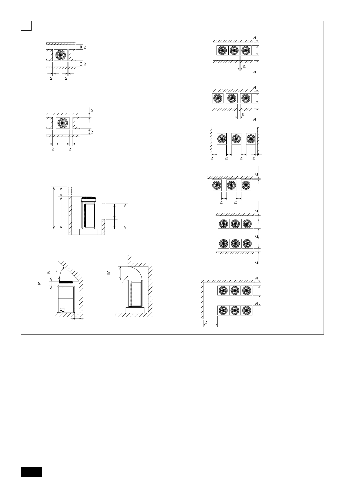
[Fig. 6.0.1]
(1)
(2)
(3)
[Fig. 6.0.2]
<A> : Top view
<B> : Side view
<C> : When there is little space up to an obstruction
A : Front
B : Unit height
C : Back
D : Air outlet guide (Procured at the site)
(4)
(mm)
A : Front
B : Must be open
C : Wall height (H)
(mm)
2
8m
8m
40
7
30mm
A
C
8m
8m
40
8m
40
8m
30mm
A
D
B
CD
D
C
A
A
CD
B
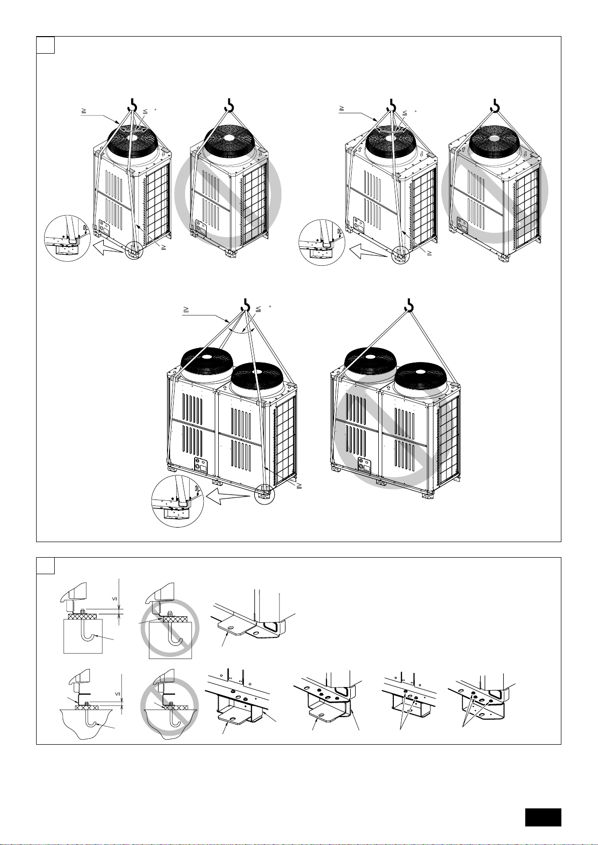
[Fig. 7.0.1]
1 P200 ~ P300
EP200
3 P450
EP300
2 P350 ~ P400
EP250
[Fig. 8.1.1]
8
<A> Without detachable leg
<B> With detachable leg
A : M10 anchor bolt procured at the site.
B : Corner is not seated.
C : Fixingbracketforhole-inanchorbolt(3locationstoxwithscrews).
D : Detachable leg
[Fig. 8.1.2]
A : Screws
3
9
B
E
A
A
2
A
1
A
B C D
e
a b c d
C
C
CCC
unit 2
A
unit 1
E
A
A
2
A
1
A
unit 2
A
unit 1
B
a
b
c d e
C
D
CC
CC
B
A
B C D
e
a b c d
C
C
CCC
A
B
A
a
b
c d e
C
D
CC
CC
A
B
B C D
e
a b c d
C
C
CCC
E
A3
A4
A2
unit 3
AAA
unit 2unit 1
E
A1
A
E
A
3
A
4
A
2
A
unit 3
AAA
unit 2unit 1
E
A
1
B
a
b
c d e
C
D
CC
CC
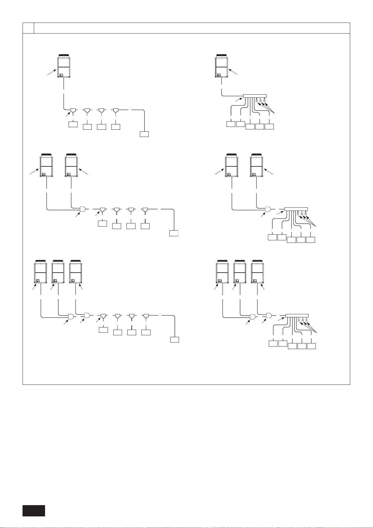
[Fig. 9.2.1]
[P200 ~ P450]
[EP200, EP250, EP300]
[P500 ~ P900]
[EP400 ~ EP600]
9.2
[P950 ~ P1250]
[EP650 ~ EP900]
A : Outdoor unit
B : First branch
C : Indoor unit
D : Cap
E : Outdoor twinning kit
4
9
<
<
<
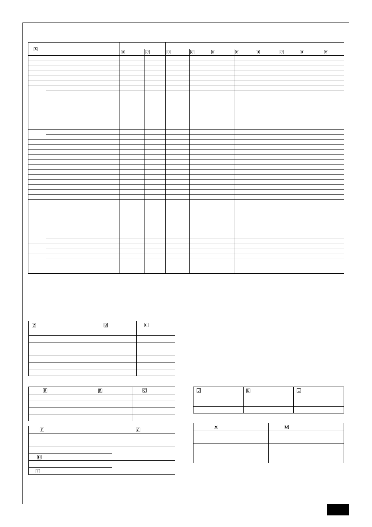
A (mm)
Outdoor model
P200 YJM-A - - - ø9.52 ø19.05 - - - - - - - P250 YJM-A - - - *1 ø9.52 ø22.2 - - - - - - - P300 YJM-A - - - *2 ø9.52 ø22.2 - - - - - - - P350 YJM-A - - - ø12.7 ø28.58 - - - - - - - P400 YJM-A - - - ø12.7 ø28.58 - - - - - - - P450 YJM-A - - - ø15.88 ø28.58 - - - - - - - -
YSJM-A P250 P250 - ø15.88 ø28.58 ø9.52 ø22.2 ø9.52 ø22.2 - - - -
P500
YSJM-A1 P300 P200 - ø15.88 ø28.58 ø12.7 ø22.2 ø9.52 ø19.05 - - - -
P550 YSJM-A P300 P250 - ø15.88 ø28.58 ø12.7 ø22.2 ø9.52 ø22.2 - - - -
YSJM-A P350 P250 - ø15.88 ø28.58 ø12.7 ø28.58 ø9.52 ø22.2 - - - -
P600
YSJM-A1 P300 P300 - ø15.88 ø28.58 ø12.7 ø22.2 ø12.7 ø22.2 - - - -
P650 YSJM-A P350 P300 - ø15.88 ø28.58 ø12.7 ø28.58 ø12.7 ø22.2 - - - -
YSJM-A P350 P350 - ø19.05 ø34.93 ø12.7 ø28.58 ø12.7 ø28.58 - - - -
P700
YSJM-A1 P400 P300 - ø19.05 ø34.93 ø15.88 ø28.58 ø12.7 ø22.2 - - - -
P750 YSJM-A P400 P350 - ø19.05 ø34.93 ø15.88 ø28.58 ø12.7 ø28.58 - - - -
YSJM-A P450 P350 - ø19.05 ø34.93 ø15.88 ø28.58 ø12.7 ø28.58 - - - -
P800
YSJM-A1 P400 P400 - ø19.05 ø34.93 ø15.88 ø28.58 ø15.88 ø28.58 - - - P850 YSJM-A P450 P400 - ø19.05 ø41.28 ø15.88 ø28.58 ø15.88 ø28.58 - - - P900 YSJM-A P450 P450 - ø19.05 ø41.28 ø15.88 ø28.58 ø15.88 ø28.58 - - - P950 YSJM-A P400 P300 P250 ø19.05 ø41.28 ø15.88 ø28.58 ø12.7 ø22.2 ø9.52 ø22.2 ø19.05 ø34.93
P1000 YSJM-A P400 P300 P300 ø19.05 ø41.28 ø15.88 ø28.58 ø12.7 ø22.2 ø12.7 ø22.2 ø19.05 ø34.93
P1050 YSJM-A P400 P350 P300 ø19.05 ø41.28 ø15.88 ø28.58 ø12.7 ø28.58 ø12.7 ø22.2 ø19.05 ø34.93
P1100 YSJM-A P400 P350 P350 ø19.05 ø41.28 ø15.88 ø28.58 ø12.7 ø28.58 ø12.7 ø28.58 ø19.05 ø34.93
P1150 YSJM-A P450 P350 P350 ø19.05 ø41.28 ø15.88 ø28.58 ø12.7 ø28.58 ø12.7 ø28.58 ø19.05 ø34.93
P1200 YSJM-A P450 P400 P350 ø19.05 ø41.28 ø15.88 ø28.58 ø15.88 ø28.58 ø12.7 ø28.58 ø19.05 ø34.93
P1250 YSJM-A P450 P450 P350 ø19.05 ø41.28 ø15.88 ø28.58 ø15.88 ø28.58 ø12.7 ø28.58 ø19.05 ø34.93
EP200 YJM-A - - - ø9.52 ø19.05 - - - - - EP250 YJM-A - - - *1 ø9.52 ø22.2 - - - - - - - EP300 YJM-A - - - *2 ø9.52 ø22.2 - - - - - - - EP400 YSJM-A EP200 EP200 - ø12.7 ø28.58 ø9.52 ø19.05 ø9.52 ø19.05 - - - EP450 YSJM-A EP250 EP200 - ø15.88 ø28.58 ø9.52 ø22.2 ø9.52 ø19.05 - - - -
YSJM-A EP300 EP200 - ø15.88 ø28.58 ø12.7 ø22.2 ø9.52 ø19.05 - - - -
EP500
YSJM-A1 EP250 EP250 - ø15.88 ø28.58 ø9.52 ø22.2 ø9.52 ø22.2 - - - -
EP550 YSJM-A EP300 EP250 - ø15.88 ø28.58 ø12.7 ø22.2 ø9.52 ø22.2 - - - EP600 YSJM-A EP300 EP300 - ø15.88 ø28.58 ø12.7 ø22.2 ø12.7 ø22.2 - - - EP650 YSJM-A EP250 EP200 EP200 ø15.88 ø28.58 ø9.52 ø22.2 ø9.52 ø19.05 ø9.52 ø19.05 ø19.05 ø34.93
YSJM-A EP300 EP200 EP200 ø19.05 ø34.93 ø12.7 ø22.2 ø9.52 ø19.05 ø9.52 ø19.05 ø19.05 ø34.93
EP700
YSJM-A1 EP250 EP250 EP200 ø19.05 ø34.93 ø9.52 ø22.2 ø9.52 ø22.2 ø9.52 ø19.05 ø19.05 ø34.93
YSJM-A EP300 EP250 EP200 ø19.05 ø34.93 ø12.7 ø22.2 ø9.52 ø22.2 ø9.52 ø19.05 ø19.05 ø34.93
EP750
YSJM-A1 EP250 EP250 EP250 ø19.05 ø34.93 ø9.52 ø22.2 ø9.52 ø22.2 ø9.52 ø22.2 ø19.05 ø34.93
YSJM-A EP300 EP300 EP200 ø19.05 ø34.93 ø12.7 ø22.2 ø12.7 ø22.2 ø9.52 ø19.05 ø19.05 ø34.93
EP800
YSJM-A1 EP300 EP250 EP250 ø19.05 ø34.93 ø12.7 ø22.2 ø9.52 ø22.2 ø9.52 ø22.2 ø19.05 ø34.93
EP850 YSJM-A EP300 EP300 EP250 ø19.05 ø41.28 ø12.7 ø22.2 ø12.7 ø22.2 ø9.52 ø22.2 ø19.05 ø34.93
EP900 YSJM-A EP300 EP300 EP300 ø19.05 ø41.28 ø12.7 ø22.2 ø12.7 ø22.2 ø12.7 ø22.2 ø19.05 ø34.93
*1 ø12.7 for over 90m
*2 ø12.7 for over 40m
*3 The pipe sizes listed in columns A1 to A3 in this table correspond to the
sizes for the models listed in the unit 1, 2, and 3 columns. When the order
of the models for unit 1, 2, and 3 change, make sure to use the appropriate
pipe size.
B, C, D (mm)
Total capacity of indoor units Liquid pipe
~ 140 ø9.52 ø15.88
141 ~ 200 ø9.52 ø19.05
201 ~ 300 ø9.52 ø22.2
301 ~ 400 ø12.7 ø28.58
401 ~ 650 ø15.88 ø28.58
651 ~ 800 ø19.05 ø34.93
801 ~ ø19.05 ø41.28
a, b, c, d, e (mm)
Model number
20,25,32,40,50 ø6.35 ø12.7
63,71,80,100,125,140 ø9.52 ø15.88
200 ø9.52 ø19.05
250 ø9.52 ø22.2
Downstream unit model total Joint
The 1st branch of P450 ~ P650
The 1st branch of P700, P750, P800
Unit combination A A1 *3 A2 *3 A3 *3 A4
unit 1 unit 2 unit 3
Liquid pipe
~ 200 CMY-Y102S-G2
201 ~ 400 CMY-Y102L-G2
401 ~ 650
651 ~
Liquid pipe Gas pipe Liquid pipe Gas pipe Liquid pipe Gas pipe Liquid pipe
Gas pipe
Gas pipe
CMY-Y202-G2
CMY-Y302-G2
9.2
4-Branching header
(Downstream unit
model total
Gas pipe
8-Branching header
200)
CMY-Y104-G CMY-Y108-G CMY-Y1010-G
Outdoor model
P500 ~ P650
EP400 ~ EP600
P700 ~ P900 CMY-Y200VBK2
P950 ~ P1250
EP650 ~ EP900
(Downstream unit
model total
400)
Liquid pipe Gas pipe
- -
10-Branching header
(Downstream unit
model total
Outdoor twinning kit
CMY-Y100VBK2
CMY-Y300VBK2
650)
5
9
A
C
F
B
C
F
F
C
2m
F
D
E
C
15
±
F
G
H
H
J
J
H
I
6
I
c
8
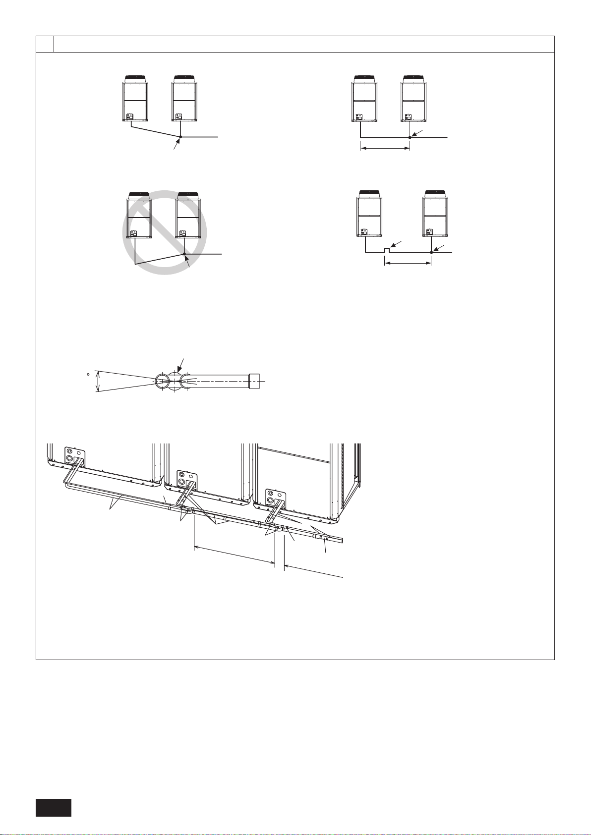
[Fig. 9.2.2]
9.2
<A> Make sure the pipes from the twinning pipe to the outdoor unit are
sloped downwards (towards the twinning pipes).
<C> Slope of twinning pipes
<D> Pipe connection example [EP650]
<B> When the piping on the outdoor unit side (from the twinning pipe)
exceeds 2 m, ensure a trap (gas pipe only) within 2 m.
A : Downward slope
B : Upward slope
C : Indoor unit
D : Trap (gas pipe only)
E : Within 2 m
F : Twinning pipe
Slope of the
G :
H : Pipes on site
I : Twinning kit
J : Straight run of pipe that is 500 mm or more
6
: ODø12.7×IDø9.52 (Included with outdoor unit)
8
: ODø19.05×IDø15.88 (Included with outdoor unit)
c
: ODø34.93×IDø28.58 (Included with outdoor unit)
(6, 8, c: Refer to item 10.2)
twinning
pipe is at an angle within ±15° to the gro
und
6
10
AB
P450
EP300
<B>
<A>
F
G
E
A
D
E
D
G
F
A
O
S
C
B
D
<B>
<A>
P200~P400
EP200,EP250
90ab
<C>
A
B
123
<C>
fed
<C>
754
<C>
90ab<C>
457<C>
A
B
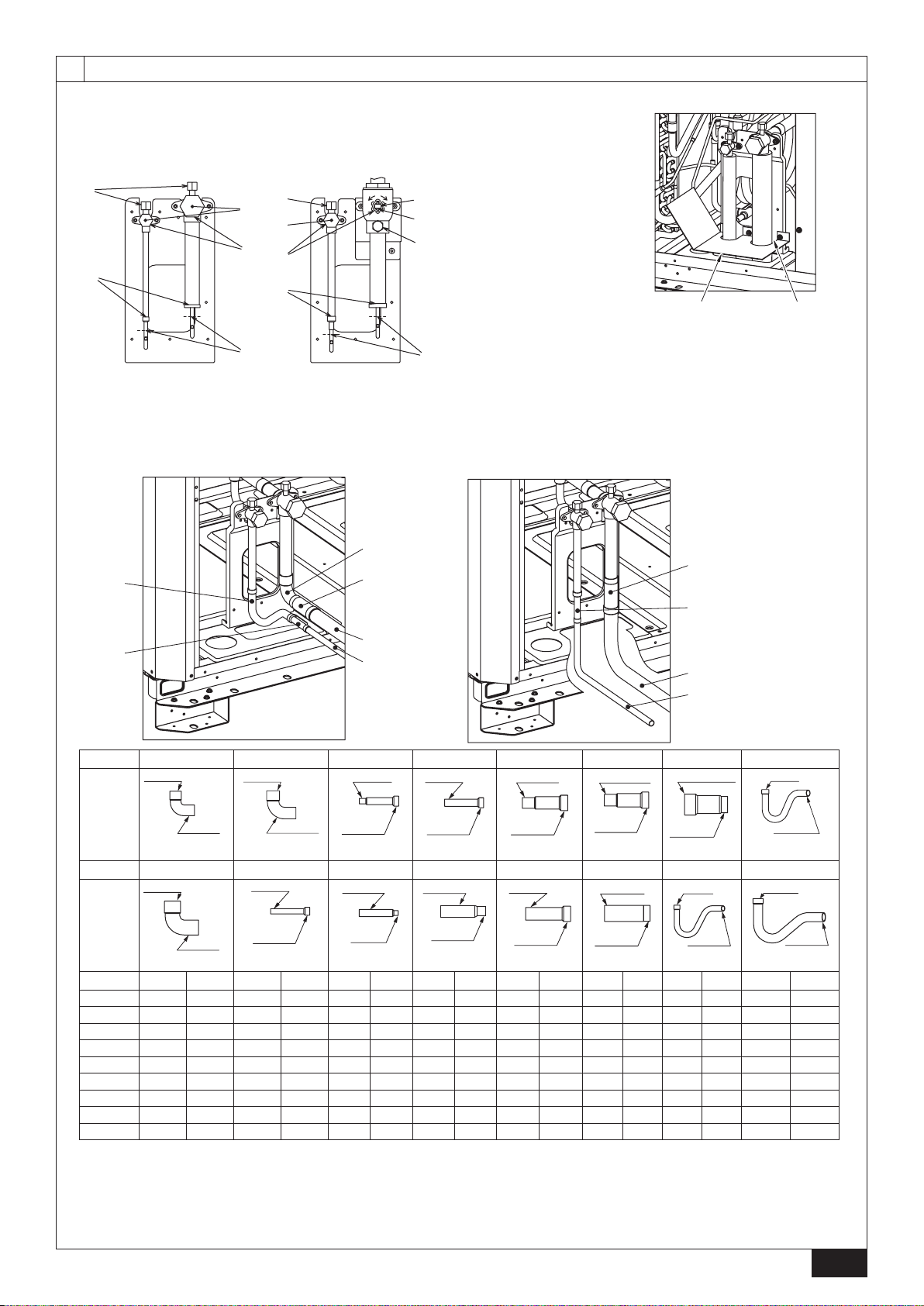
[Fig. 10.2.1] [Fig. 10.2.3]
[Fig. 10.2.2]
<A> Front pipe routing
10.2
<A> Refrigerant service valve
(liquid side/brazed type)
<B> Refrigerant service valve
(gas side/brazed type)
A : Shaft
B : Shaft
C : Stopper pin
D : Service port
E : Cap
F : Pinched connecting pipe severing portion
G : Pinched connecting pipe brazing portion
<B> Bottom pipe routing
A : Exampleofclosurematerials(eldsupply)
B : Fill the gap at the site
No.
C Shape
No.
C Shape
P200 1 1
P250 1 1 1
P300 1 1 1 1
P350 1 1 1 1
P400 1 1 1 1
P450 1 1
EP200 1 1 1
EP250 1 1 1 1 1 1 1 1
EP300 1 1 1 1 1
<A> Front pipe routing <B> Bottom pipe routing
<C> Included with outdoor unit
AGaspipe(eldsupplyrequired) BLiquidpipe(eldsupplyrequired)
C Shape
*4: EP650YSJM-A : Use the included connecting pipe 6 , 8, and c to connect to the twinning kit.
*5: EP700YSJM-A1 : Use the included connecting pipe 6 to connect to the twinning kit.
*6: EP750YSJM-A1 : Use the included connecting pipe 6 to connect to the twinning kit.
(*4 ~ *6 : Refer to item 9.2.)
1 3 5 7 9 a c e
IDø19.05
ODø19.05
<Gas side>
2 4 6 8 0 b d f
IDø25.4
ODø25.4
<Gas side>
1 2 3 4 5 6 7 8 9 0 a b c d e f
IDø28.58
<Gas side>
ODø9.52
IDø12.7
<Liquid side>
ODø28.58
ODø9.52
IDø15.88
<Liquid side>
ODø12.7
IDø9.52
<Liquid side>
ODø12.7
IDø15.88
<Liquid side>
ODø19.05
IDø15.88
<Liquid side>
ODø19.05
IDø25.4
<Gas side>
ODø22.2
IDø25.4
<Gas side>
ODø22.2
IDø28.58
<Gas side>
ODø28.58
IDø25.4
<Gas side>
ODø34.93
IDø28.58
<Gas side>
IDø9.52
ODø9.52
<Liquid side>
IDø12.7
ODø12.7
<Liquid side>
IDø15.88
ODø15.88
<Liquid side>
7
10.3
A
D
C
C
B
B
E
F
G
H
I
J
A
LOW
HI
LOW
HI
B
A
K
J
L
H
M
C
D
EN
N
O
F
G
I
C
A
B
D
E
B
A
D
C
E
E
E
D
A
B
A B
A B
D
C
D
F
G
B
E
I
B
F
H
D
B
G
I
A
J
1m1m
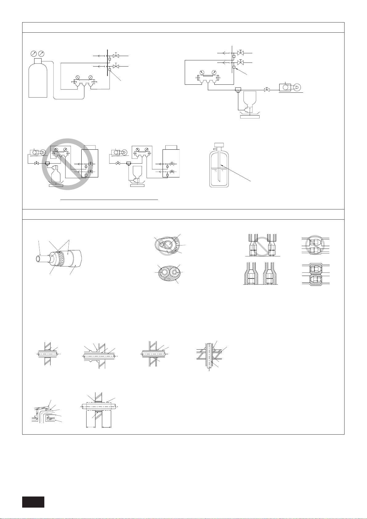
[Fig. 10.3.1]
[Fig. 10.3.3]
A : Nitrogen gas
B : To indoor unit
C : System analyzer
D : Low knob
E : Hi knob
F : Valve
G : Liquid pipe
H : Gas pipe
I : Outdoor unit
J : Service port
B In case of the R410A cylinder having no syphon pipe.
[Fig. 10.3.2]
10.4
A : System analyzer
B : Low knob
C : Hi knob
D : Valve
E : Liquid pipe
F : Gas pipe
G : Service port
H : Three-way joint
I : Valve
J : Valve
K : R410A cylinder
L : Scale
M : Vacuum pump
N : To indoor unit
O : Outdoor unit
A : Syphon pipe
[Fig. 10.4.1]
A : Steel wire B : Piping
C : Asphaltic oily mastic or asphalt
D : Heat insulation material A
E : Outer covering B
[Fig. 10.4.4]
<A> Inner wall (concealed)
<E> Roof pipe shaft
<F> Penetrating portion on re
limit and boundary wall
<B> Outer wall
A : Liquid pipe B : Gas pipe
C : Electric wire D : Finishing tape
E : Insulator
<C> Outer wall (exposed)
A : Sleeve B : Heat insulating material
C : Lagging D : Caulking material
E : Band F : Waterproong layer
G : Sleeve with edge H : Lagging material
I : Mortar or other incombustible caulking
J : Incombustible heat insulation material
<D> Floor (waterproong)
[Fig. 10.4.3][Fig. 10.4.2]
8
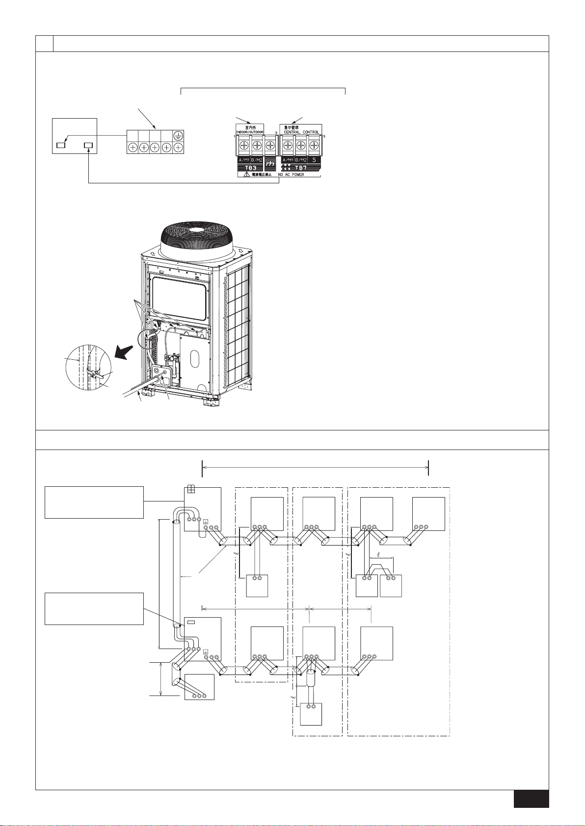
C
L1 L2 L3 N
Terminal block for indoor –
outdoor transmission line
(TB3)
Terminal block for
centralized control
(TB7)
Power supply terminal block
(TB1)
Control box
A
B
11
A B C
E
D
M1M2
M1M2
S
TB7
TB3
IC
(51)
M1 M2 S
TB5
RC
(01)
IC
M1 M2 S
TB5
(02)
IC
M1 M2 S
TB5
(04)
IC
M1 M2 S
TB5
(03)
IC
M1 M2 S
TB5
(05)
IC
M1 M2 S
TB5
(07)
IC
M1 M2 S
TB5
(06)
L
2
L
1
(101)
RC
(105)
RC
(103)
RC
(155)
OC
M1M2
M1M2
S
TB7
TB3
CN40
(52)
OC
3
ABS
System
controller
L
3
L
6
L
4
L
5
2
4
1
AB AB AB
AB
CN40
A
B
C
D
A
B
[Fig. 11.2.1]
[Fig. 11.2.2]
A : Cable strap
B : Power source line
C : Transmission line
D : Pillar
11.2
A : Power source
B : Transmission line
C : Earth screw
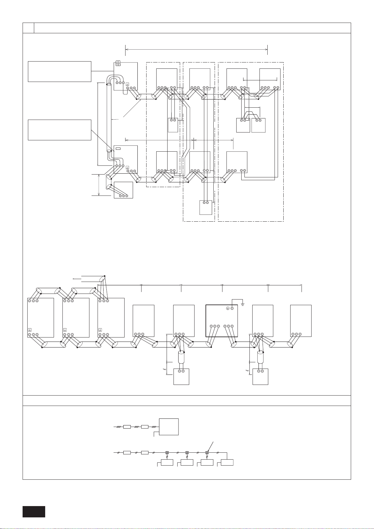
[Fig. 11.3.1]
<A> Change the jumper connector
from CN41 to CN40 *1
<B> SW2-1:ON *2
( ) Address
<C> Keep the jumper connector
on CN41
<B> SW2-1:ON *2
*1: When the power supply unit is not connected to the transmission line for centralized control, disconnect the male power supply
connector (CN41) from ONE outdoor unit in the system and connect it to CN40.
*2: If a system controller is used, set SW2-1 on all of the outdoor units to ON.
11.3
9
A B C
E
D
M1 M2
M1 M2
M1M2
S
TB7
TB3
IC
(51)
M1 M2 12S
TB5TB15
12
TB15
12
TB15
12
TB15
12
TB 15
12
TB15
MA
(01)
IC
M1 M2 S
TB5
(02)
IC
M1 M2 S
TB5
(04)
IC
M1 M2 S
TB5
(03)
IC
M1 M2 S
TB5
(05)
IC
M1 M2 S
TB5
(07)
IC
M1 M2 S
TB5
(06)
L
2
L
1
MAMAMA
OC
M1M2
S
TB7
TB3
(52)
OC
m
1
m
1
m
1
m
4
m
3
S
System
controller
L
3
L
6
L
4
ABABAB
AB
AB
m
2
m
2
m
2
CN40
CN40
RC
IC
M1M2 S
TB5
IC
M1M2 S
TB5
RP
Ground
AB
ABAB
S
TB2
ABS
TB3
L
4
1
1
M1M2
TB3
M1M2
TB3
M1M2
M1M2 S
TB3
TB7
M1M2 S
TB7
M1M2 S
TB7
OC
(51)
L
7
RC
IC
M1M2 S
TB5
IC
M1M2 S
TB5
L
6
L
5
L
3
L
2
L
1
OS1
(52)
OS2
(53)
To another
refrigerant system
BA
C
3N~380–415V
L
1
, L2, L
3,
N
BA
~220–240V
L, N
Earth
Earth EarthEEarth Earth
E
D
E E
11
[Fig. 11.3.2]
<A> Change the jumper connector
from CN41 to CN40 *1
<B> SW2-1:ON *2
<C> Keep the jumper connector
on CN41
<B> SW2-1:ON *2
A : Group 1
B : Group 3
C : Group 5
D : Shielded wire
E : Sub remote
controller
( ) Address
11.3
*1: When the power supply unit is not connected to the transmission line for centralized control, disconnect the male power supply
connector (CN41) from ONE outdoor unit in the system and connect it to CN40.
*2: If a system controller is used, set SW2-1 on all of the outdoor units to ON.
[Fig. 11.3.3]
( ) Address
11.4
[Fig. 11.4.1]
A : Switch (Breakers for
wi ri ng and c urre nt
leakage)
B : Breakers for current
C : Outdoor unit
D : Pull box
E : Indoor unit
leakage
10
Contents
1. Safety precautions ......................................................................................11
1.1. Before installation and electric work ...........................................11
1.2. Precautions for devices that use R410A refrigerant .................. 12
1.3. Before installation ...................................................................... 12
1.4. Before installation (relocation) - electrical work ......................... 12
1.5. Before starting the test run ........................................................ 12
2. About the product ....................................................................................... 12
3. Combination of outdoor units ..................................................................... 13
4. Specications ............................................................................................. 13
5. Conrmation of parts attached ................................................................... 14
6. Space required around unit ........................................................................ 14
7. Lifting method ............................................................................................ 14
8. Installation of unit ....................................................................................... 15
8.1. Installation ................................................................................. 15
9. Refrigerant piping installation ..................................................................... 15
9.1. Caution ...................................................................................... 15
9.2. Refrigerant piping system ........................................................ 16
1. Safety precautions
1.1. Before installation and electric work
u Before installing the unit, make sure you read all the
“Safety precautions”.
u The “Safety precautions” provide very important points
regarding safety. Make sure you follow them.
Symbols used in the text
Warning:
Describes precautions that should be observed to prevent danger of injury
or death to the user.
Caution:
Describes precautions that should be observed to prevent damage to the
unit.
Symbols used in the illustrations
: Indicates an action that must be avoided.
: Indicates that important instructions must be followed.
: Indicates a part which must be grounded.
: Beware of electric shock. (This symbol is displayed on the main unit
label.) <Color: yellow>
Warning:
Carefully read the labels afxed to the main unit.
HIGH VOLTAGE WARNING:
Con• trol box houses high-voltage parts.
When opening or closing the front panel of the control box, do not let it •
come into contact with any of the internal components.
Before inspecting the inside of the control box, turn off the power, •
keep the unit off for at least 10 minutes, and conrm that the voltage
between FT-P and FT-N on INV Board has dropped to DC20V or less.
(It takes about 10 minutes to discharge electricity after the power
supply is turned off.)
Warning:
Ask the dealer or an authorized technician to install the air conditioner.•
- Improper installation by the user may result in water leakage, electric
shock, or re.
This appliance is not intended for use by persons (including children)•
with reduced physical, sensory or mental capabilities, or lack of
experience and knowledge, unless they have been given supervision
or instruction concerning use of the appliance by a person responsible
for their safety.
Install the unit at a place that can withstand its weight.•
- Failure to do so may cause the unit to fall down, resulting in injuries and
damage to the unit.
Use the specied cables for wiring. Make the connections securely so •
that the outside force of the cable is not applied to the terminals.
- Inadequate connection and fastening may generate heat and cause a re.
Prepare for strong winds and earthquakes and install the unit at the •
specied place.
- Improper installation may cause the unit to topple and result in injury and
damage to the unit.
Always use lters and other accessories specied by Mitsubishi •
Electric.
- Ask an authorized technician to install the accessories. Improper
installation by the user may result in water leakage, electric shock, or re.
10. Additional refrigerant charge ...................................................................... 16
10.1. Calculation of additional refrigerant charge ............................... 16
10.2. Precautions concerning piping connection and
valve operation .......................................................................... 17
10.3. Airtight test, evacuation, and refrigerant charging ..................... 18
10.4. Thermal insulation of refrigerant piping ..................................... 18
11. Wiring
12. Test run ...................................................................................................... 22
13. Information on rating plate ......................................................................... 22
(For details, refer to the installation manual of each unit and controller.)
11.1. Caution ...................................................................................... 19
11.2. Control box and connecting position of wiring ........................... 19
11.3. Wiring transmission cables ....................................................... 19
11.4. Wiring of main power supply and equipment capacity .............. 21
12.1. The following phenomena do not represent faults. ................... 22
Never repair the unit. If the air conditioner must be repaired, consult •
the dealer.
- If the unit is repaired improperly, water leakage, electric shock, or re may
result.
If the supply cord is damaged, it must be replaced by the manufacturer, •
its service agent or similarly qualied persons in order to avoid a
hazard.
Do not touch the heat exchanger ns.•
- Improper handling may result in injury.
If refrigerant gas leaks during installation work, ventilate the room.•
- If the refrigerant gas comes into contact with a ame, poisonous gases will
be released.
Install the air conditioner according to this Installation Manual.•
- If the unit is installed improperly, water leakage, electric shock, or re may
result.
Have all electric work done by a licensed electrician according to•
Facility Engineering Standard” and “Interior Wire Regulations” and the
instructions given in this manual and always use a dedicated power
supply.
- If the power source capacity is inadequate or electric work is performed
improperly, electric shock and re may result.
Securely install the outdoor unit terminal cover (panel).•
- If the terminal cover (panel) is not installed properly, dust or water may
enter the outdoor unit and re or electric shock may result.
When installing and moving the air conditioner to another site, do not •
charge it with a refrigerant different from the refrigerant specied on
the unit.
- If a different refrigerant or air is mixed with the original refrigerant, the
refrigerant cycle may malfunction and the unit may be damaged.
If the air conditioner is installed in a small room, measures must be •
taken to prevent the refrigerant concentration from exceeding the
safety limit if the refrigerant should leak.
- Consult the dealer regarding the appropriate measures to prevent the
safety limit from being exceeded. Should the refrigerant leak and cause
the safety limit to be exceeded, hazards due to lack of oxygen in the room
could result.
When moving and reinstalling the air conditioner, consult the dealer or •
an authorized technician.
- If the air conditioner is installed improperly, water leakage, electric shock,
or re may result.
After completing installation work, make sure that refrigerant gas is not •
leaking.
- If the refrigerant gas leaks and is exposed to a fan heater, stove, oven, or
other heat source, it may generate noxious gases.
Do not reconstruct or change the settings of the protection devices.•
- If the pressure switch, thermal switch, or other protection device is shorted
or operated forcibly, or parts other than those specied by Mitsubishi
Electric are used, re or explosion may result.
To dispose of this product, consult your dealer.•
The installer and system specialist shall secure safety against leakage •
according to local regulation or standards.
- The size of the wire and capacities of the switch for the main power supply
are applicable if local regulations are not available.
Pay special attention to the place of installation, such as a basement, •
etc. where refrigeration gas can accumulate, since refrigeration is
heavier than the air.
For outdoor units that allow fresh air intake to the indoor unit, the •
installation site must be carefully chosen because outdoor air can
directly blow into the room when the thermostat is turned off.
- Direct exposure to outdoor air may have harmful effects on people or food.
Children should be supervised to ensure that they do not play with the •
appliance.
........ 19
“Electric
GB
11
1.2. Precautions for devices that use
R410A refrigerant
Caution:
Do not use existing refrigerant piping.•
- The old refrigerant and refrigerant oil in the existing piping contains a large
amount of chlorine which may cause the refrigerant oil of the new unit to
deteriorate.
- R410A is a high-pressure refrigerant and can cause the existing piping to burst.
Use refrigerant piping made of phosphorus deoxidized copper and •
copper alloy seamless pipes and tubes. In addition, be sure that the
inner and outer surfaces of the pipes are clean and free of hazardous
sulphur, oxides, dust/dirt, shaving particles, oils, moisture, or any other
contaminant.
- Contaminants on the inside of the refrigerant piping may cause the
refrigerant residual oil to deteriorate.
Store the piping to be used during installation indoors and keep both •
ends of the piping sealed until just before brazing. (Store elbows and
other joints in a plastic bag.)
- If dust, dirt, or water enters the refrigerant cycle, deterioration of the oil and
GB
compressor failure may result.
Apply a small amount of ester oil, ether oil, or alkyl benzene to ares. •
(for indoor unit)
- Inltration of a large amount of mineral oil may cause the refrigerant oil to
deteriorate.
Use liquid refrigerant to ll the system.•
- If gas refrigerant is used to ll the system, the composition of the
refrigerant in the cylinder will change and performance may drop.
Do not use a refrigerant other than R410A.•
- If another refrigerant (R22, etc.) is mixed with R410A, the chlorine in the
refrigerant may cause the refrigerant oil to deteriorate.
Use a vacuum pump with a reverse ow check valve.•
- The vacuum pump oil may ow back into the refrigerant cycle and cause
the refrigerant oil to deteriorate.
Do not use the following tools that are used with conventional •
refrigerants.
(Gauge manifold, charge hose, gas leak detector, reverse ow check
valve, refrigerant charge base, refrigerant recovery equipment)
- If the conventional refrigerant and refrigerant oil are mixed in the R410A,
the refrigerant may deteriorated.
- If water is mixed in the R410A, the refrigerant oil may deteriorate.
- Since R410A does not contain any chlorine, gas leak detectors for
conventional refrigerants will not react to it.
Do not use a charging cylinder.•
- Using a charging cylinder may cause the refrigerant to deteriorate.
Be especially careful when managing the tools.•
- If dust, dirt, or water gets into the refrigerant cycle, the refrigerant may
deteriorate.
1.3. Before installation
Caution:
Do not install the unit where combustible gas may leak.•
- If the gas leaks and accumulates around the unit, an explosion may result.
Do not use the air conditioner where food, pets, plants, precision •
instruments, or artwork are kept.
- The quality of the food, etc. may deteriorate.
Do not use the air conditioner in special environments.•
- Oil, steam, sulfuric smoke, etc. can signicantly reduce the performance of
the air conditioner or damage its parts.
When installing the unit in a hospital, communication station, or similar •
place, provide sufcient protection against noise.
- Inverter equipment, private power generator, high-frequency medical
equipment, or radio communication equipment may cause the air
conditioner to operate erroneously, or fail to operate. On the other hand,
the air conditioner may affect such equipment by creating noise that
disturbs medical treatment or image broadcasting.
Do not install the unit on a structure that may cause leakage.•
- When the room humidity exceeds 80% or when the drain pipe is clogged,
condensation may drip from the indoor unit. Perform collective drainage
work together with the outdoor unit, as required.
1.4.
Before installation (relocation) electrical work
Caution:
Ground the unit.•
- Do not connect the ground wire to gas or water pipes, lightning rods, or
telephone ground lines. Improper grounding may result in electric shock.
Never connect in reverse phases. •
Never connect the Power Line L1, L2, and L3 to Terminal N.
- If the unit is miss wired, when power is supplied, some electrical parts will
be damaged.
Install the power cable so that tension is not applied to the cable.•
- Tension may cause the cable to break and generate heat and cause a re.
Install a leak circuit breaker, as required.•
- If a leak circuit breaker is not installed, electric shock may result.
Use power line cables of sufcient current carrying capacity and rating.•
- Cables that are too small may leak, generate heat, and cause a re.
Use only a circuit breaker and fuse of the specied capacity.•
- A fuse or circuit breaker of a larger capacity, or the use of a substitute
simple steel or copper wire may result in a general unit failure or re.
Do not wash the air conditioner units.•
- Washing them may cause an electric shock.
Be careful that the installation base is not damaged by long use.•
- If the damage is left uncorrected, the unit may fall and cause personal
injury or property damage.
Install the drain piping according to this Installation Manual to ensure •
proper drainage. Wrap thermal insulation around the pipes to prevent
condensation.
- Improper drain piping may cause water leakage causing damage to
furniture and other possessions.
Be very careful about transporting the product.•
- One person should not carry the product. Its weight is in excess of 20kg.
- Some products use PP bands for packaging. Do not use any PP bands as
a means of transportation. It is dangerous.
- Do not touch the heat exchanger ns. Doing so may cut your ngers.
- When transporting the outdoor unit, support it at the specied positions on
the unit base. Also support the outdoor unit at four points so that it cannot
slip sideways.
Safely dispose of the packing materials.•
- Packing materials, such as nails and other metal or wooden parts, may
cause stabs or other injuries.
- Tear apart and throw away plastic packaging bags so that children will not
play with them. If children play with a plastic bag which has not been torn
apart, they face the risk of suffocation.
1.5. Before starting the test run
Caution:
Turn on the power at least 12 hours before starting operation.•
- Starting operation immediately after turning on the main power switch can
result in irreversible damage to internal parts. Keep the power switch turned
on during the operational season. Make sure of the phase order of power
supply and voltage between each phase.
Do not touch the switches with wet ngers.•
- Touching a switch with wet ngers can result in an electric shock.
Do not touch the refrigerant pipes during and immediately after •
operation.
- During and immediately after operation, the refrigerant pipes may be hot
or cold, depending on the condition of the refrigerant owing through the
refrigerant piping, compressor, and other refrigerant cycle parts. Your hands
may suffer burns or frostbite if you touch the refrigerant pipes.
Do not operate the air conditioner with the panels and guards removed.•
- Rotating, hot, or high-voltage parts can cause injuries.
Do not turn off the power immediately after stopping operation.•
- Always wait at least 5 minutes before turning off the power. Otherwise,
drainage water leakage or mechanical failure of sensitive parts may occur.
Do not touch the surface of the compressor during servicing.•
- If unit is connected to a supply and not running, the crank case heater
located at the base of the compressor may still be operating.
2. About the product
This unit uses R410A-type refrigerant.•
Piping for systems using R410A may be different from that for systems using •
conventional refrigerant because the design pressure in systems using
R410A is higher. Refer to the Data Book for more information.
Some of the tools and equipment used for installation with systems that use •
other types of refrigerant cannot be used with the systems using R410A.
Refer to the Data Book for more information.
12
Do not use the existing piping, as it contains chlorine, which is found in •
conventional refrigerating machine oil and refrigerant. This chlorine will
deteriorate the refrigerant machine oil in the new equipment. The existing
piping must not be used as the design pressure in systems using R410A
is higher than that in the systems using other types of refrigerant and the
existing pipes may burst.
Caution:
Do not vent R410A into the atmosphere.•
R410A is a Fluorinated Greenhouse gas, covered by the Kyoto Protocol •
with a Global Warming Potential (GWP) = 1975.
 Loading...