

Mitsubishi PUHY-EP200, PUHY-EP300, PUHY-EP450YKM-A, PUHY-EP450YSKM-A, PUHY-EP500 Service Handbook
...Page 1
Page 2
Safety Precautions
Please read the following safety precautions carefully before installing the unit to ensure safety.
Indicates a risk of death or serious injury.
Indicates a risk of serious injury or structural damage.
Make sure that this manual is passed on to the end user to retain for future reference.
Retain this manual for future reference. When the unit is reinstalled or repaired, have this manual available to those who pro-
vide these services. Make sure that this manual is passed on to any future users.
All electric work must be performed by qualified personnel.
Air tightness test must be performed by qualified personnel.
[1] General Precautions
General Precautions
Do not use refrigerant other than the type indicated in the manuals provided with the
unit and on the nameplate. Doing so may
cause the unit or pipes to burst, or result in
explosion or fire during use, during repair,
or at the time of disposal of the unit. It may
also be in violation of applicable laws. MITSUBISHI ELECTRIC CORPORATION cannot
be held responsible for malfunctions or accidents resulting from the use of the wrong
type of refrigerant.
Do not install the unit in a place where large
amounts of oil, steam, organic solvents, or
corrosive gases, such as sulfuric gas, are
present or where acidic/alkaline solutions
or sprays containing sulfur are used frequently. These substances can compromise the performance of the unit or cause
certain components of the unit to corrode,
which can result in refrigerant leakage, water leakage, injury, electric shock, malfunctions, smoke, or fire.
Do not try to defeat the safety features of the
unit or make unauthorized setting changes.
Forcing the unit to operate the unit by defeating the safety features of the devices
such as the pressure switch or the temperature switch, making unauthorized changes
to the switch settings, or using accessories
other than the ones recommended by Mitsubishi Electric may result in smoke, fire, or
explosion.
To reduce the risk of shorting, current leakage, electric shock, malfunctions, smoke, or
fire, do not splash water on electric parts.
To reduce the risk of electric shock, malfunctions, smoke or fire, do not operate the
switches/buttons or touch other electrical
parts with wet hands.
To reduce the risk of pipe burst and explosion, do not allow gas refrigerant and refrigerant oil to be trapped in the refrigerant
circuit.
To reduce the risk of burns or frost bites, do
not touch the refrigerant pipes or refrigerant
circuit components with bare hands during
and immediately after operation.
To reduce the risk of burns, do not touch
any electrical parts with bare hands during
or immediately after stopping operation.
To reduce the risk of injury from falling
tools, keep children away while installing,
inspecting, or repairing the unit.
Keep the space well ventilated. Refrigerant
can displace air and cause oxygen starvation. If leaked refrigerant comes in contact
with a heat source, toxic gas may be generated.
i
Page 3
Always replace a fuse with one with the correct current rating. The use of improperly
rated fuses or a substitution of fuses with
steel or copper wire may result in bursting,
fire or explosion.
To reduce the risk of electric shock, smoke,
and fire due to infiltration of dust and water,
properly install all required covers and panels on the terminal box and control box.
To reduce the risk of injury from units falling
or falling over, periodically check the installation base for damage.
Consult an authorized agency for the proper
disposal of the unit. Refrigerant oil and refrigerant that may be left in the unit pose a
risk of fire, explosion, or environmental pollution.
To reduce the risk of being caught in rotating parts, electric shock, and burns, do not
operate the unit without all required panels
and guards being installed.
To reduce the risk of injury, do not sit,
stand, or place objects on the unit.
To reduce the risk of water leakage and malfunctions, do not turn off the power immediately after stopping operation. Leave the
unit turned on for at least 5 minutes before
turning off the power.
Do not install the unit over things that are
vulnerable to water damage from condensation dripping.
To reduce the risk of injury, electric shock,
and malfunctions, do not touch or allow cables to come in contact with the edges of
components.
To reduce the risk of injury, do not touch the
heat exchanger fins or sharp edges of components with bare hands.
[2] Transportation and Installation
Always wear protective gears when touching electrical components on the unit. Several minutes after the power is switched off,
residual voltage may still cause electric
shock.
To reduce the risk of electric shock and
burns, always wear protective gear when
working on units.
To reduce the risk of injury, do not insert fingers or foreign objects into air inlet/outlet
grills. If the unit is left on a damaged base, it
may fall and cause injury.
To reduce the risk of injury, always wear
protective gear when working on units.
Do not release refrigerant into the atmosphere. Collect and reuse the refrigerant, or
have it properly disposed of by an authorized agency. Refrigerant poses environmental hazards if released into the air.
Transportation and Installation
Lift the unit by placing the slings at designated locations. Support the outdoor unit
securely at four points to keep it from slipping and sliding. If the unit is not properly
supported, it may fall and cause personal
injury.
To reduce the risk of injury, do not carry the
product by the PP bands that are used on
some packages.
To reduce the risk of injury, products weighing 20 kg or more should be carried by two
or more people.
ii
Page 4
[3] Installation
Installation
Do not install the unit where there is a risk
of leaking flammable gas.
If flammable gas accumulates around the
unit, it may ignite and cause a fire or explosion.
To reduce the risk of injury from coming in
contact with units, install units where they
are not accessible to people other than
maintenance personnel.
To reduce the risk of injury, properly dispose of the packing materials so that children will not play with them.
Properly dispose of the packing materials.
Plastic bags pose suffocation hazard to
children.
All drainage work should be performed by
the dealer or qualified personnel according
to the instructions detailed in the Installation Manual. Improper drainage work may
cause water leakage and resultant damage
to the furnishings.
Remove packing materials from the unit before operating the unit. Note that some accessories may be taped to the unit. Properly
install all accessories that are required. Failing to remove the packing materials or failing to install required accessories may
result in refrigerant leakage, oxygen deprivation, smoke, or fire.
Consult your dealer and take appropriate
measures to safeguard against refrigerant
leakage and resultant oxygen starvation. An
installation of a refrigerant gas detector is
recommended.
Any additional parts must be installed by
the dealer or qualified personnel. Only use
the parts specified by Mitsubishi Electric.
Installation by unauthorized personnel or
use of unauthorized parts or accessories
may result in water leakage, electric shock,
or fire.
Take appropriate safety measures against
wind gusts and earthquakes to prevent the
unit from toppling over and causing injury.
Do not install the unit over things that are
vulnerable to water damage. Provide an adequate collective drainage system for the
drain water from unit as necessary.
To reduce the risk of damage to the unit and
resultant electric leak and electric shock,
keep small animals, snow, and rain water
from entering the unit by closing the gap in
the pipe and wire access holes.
[4] Piping Work
Piping Work
To reduce the risk of injury, including frost
bites, that may result from being blasted
with refrigerant, use caution when operating the refrigerant service valve. If refrigerant leaks out and comes in contact with an
open flame, toxic gases may be generated.
To reduce the risk of injury from units falling
or falling over, install the unit on a surface
that is strong enough to support its weight.
To reduce the risk of rain water or drain water from entering the room and damaging
the interior, drainage work must be performed by your dealer or qualified personnel according to the instructions detailed in
the Installation Manual.
To reduce the risk of refrigerant catching
fire and causing burns, remove the refrigerant gas and the residual refrigerant oil in the
pipes before heating them.
iii
Page 5
To reduce the risk of pipe damage, refrigerant leakage, and oxygen deprivation, use
pipes that meet the pipe thickness specifications, which vary by the type of refrigerant used, pipe diameter, and pipe material.
To reduce the risk of pipe burst or explosion, evacuate the refrigerant circuit using a
vacuum pump, and do not purge the system
with refrigerant.
To reduce the risk of explosion and deterioration of refrigerant oil caused by chloride,
do not use oxygen, flammable gas, or refrigerant that contains chloride as a pressurizing gas.
To prevent explosion, do not heat the unit
with refrigerant gas in the refrigerant circuit.
To reduce the risk of oxygen deprivation
and gas poisoning, check for gas leakage
and keep fire sources away.
Insulate pipe connections after completing
the air tightness test. Performing an air
tightness test with the pipe being insulated
may lead to failure to detect refrigerant leakage and cause oxygen deprivation.
To reduce the risk of pipe damage and resultant refrigerant leakage and oxygen deprivation, keep the field-installed pipes out
of contact with the edges of components.
To reduce the risk of pipe bursting and explosion due to abnormal pressure rise, do
not allow any substances other than R410A
(such as air) to enter the refrigerant circuit.
[5] Wiring Work
Wiring Work
To reduce the risk of wire breakage, overheating, smoke, and fire, keep undue force
from being applied to the wires.
To reduce the risk of wire breakage, overheating, smoke, or fire, properly secure the
cables in place and provide adequate slack
in the cables so as not to stress the terminals.
All electric work must be performed by a
qualified electrician according to the local
regulations, standards, and the instructions
detailed in the Installation Manual. Capacity
shortage to the power supply circuit or improper installation may result in malfunction, electric shock, smoke, or fire.
To reduce the risk of electric shock, smoke,
or fire, install an inverter circuit breaker on
the power supply to each unit.
To keep the ceiling and floor from getting
wet due to condensation, properly insulate
the pipes.
Use properly rated breakers and fuses (inverter circuit breaker, local switch <switch +
fuse>, no-fuse breaker). The use of a breaker with a breaking capacity greater than the
specified capacity may cause electric
shock, malfunctions, smoke, or fire.
To reduce the risk of current leakage, overheating, smoke, or fire, use properly rated
cables with adequate current carrying capacity.
Proper grounding must be provided by a licensed electrician.
Do not connect the grounding wire to a gas
pipe, water pipe, lightning rod, or telephone
wire. Improper grounding may result in
electric shock, smoke, fire, or malfunction
due to electrical noise interference.
To reduce the risk of current leakage, wire
breakage, smoke, or fire, keep the wiring
out of contact with the refrigerant pipes and
other parts, especially sharp edges.
iv
Page 6

[6] Relocation and Repairs
Relocation and Repairs
To reduce the risk of refrigerant leakage,
water leakage, injury, electric shock, and
fire, units should only be moved or repaired
by your dealer or qualified personnel.
To reduce the risk of wire shorting, electric
shock, malfunctions, or fire, keep circuit
boards dust free, and do not touch them
with your hands or tools.
[7] Additional Precautions
Additional Precautions
To avoid damage to the unit, use appropriate tools to install, inspect, or repair the
unit.
To reduce the risk or malfunction, turn on
the power at least 12 hours before starting
operation, and leave the power turned on
throughout the operating season.
Recover all refrigerant in the units, and dispose of it properly according to any applicable laws and regulations.
Provide a maintenance access to allow for
the inspection of pipes above the ceiling or
the buried pipes.
Take appropriate measures against electrical noise interference when installing the air
conditioners in hospitals or facilities with
radio communication capabilities. Inverter,
high-frequency medical, or wireless communication equipment as well as power
generators may cause the air conditioning
system to malfunction. Air conditioning
system may also adversely affect the operation of these types of equipment by creating
electrical noise.
To reduce the risk of damage to the unit,
leave the valves on the unit closed until refrigerant charging is completed.
Place a wet towel on the refrigerant service
valve before brazing the pipes to keep its
temperature from rising above 120ºC and
damaging the surrounding equipment.
To reduce the risk of wire shorting, electric
leak, electric shock, smoke, or fire, do not
perform maintenance work in the rain.
To reduce the risk of injury, electric shock,
and fire, properly reinstall all removed components after completing repair work.
To reduce the risk of refrigerant and water
leakage, check the pipe supports and insulation for damage during inspection or repair, and replace or repair the ones that are
found to be deteriorated.
Direct the blazing torch flame away from the
adjacent cables and sheet metal to keep
them from being overheated and damaged.
Prepare tools for exclusive use with R410A.
Do not use the following tools if they have
been used with the conventional refrigerant
(R22): gauge manifold, charging hose, refrigerant leak detector, check valve, refrigerant charge spout, vacuum gauge, and
refrigerant recovery equipment. R410A
does not contain chloride, so leak detectors
for use with older types of refrigerants will
not detect an R410A leak. Infiltration of the
residual refrigerant, refrigerant oil, or water
on these tools may cause the refrigerant oil
in the new system to deteriorate or damage
the compressor.
To reduce the risk of the vacuum pump oil
backflowing into the refrigerant cycle and
causing the refrigerant oil to deteriorate,
use a vacuum pump with a check valve.
Have a set of tools for exclusive use with
R410A. Consult your nearest Mitsubishi
Electric Dealer.
Keep dust, dirt, and water off charging hose
and flare tool. Infiltration of dust, dirt, or water into the refrigerant circuit may cause the
refrigerant oil to deteriorate or damage the
compressor.
v
Page 7

Use refrigerant piping and couplings that
meet the applicable standards. For refrigerant pipes, use pipes made of phosphorus
deoxidized copper. Keep the inner and outer surfaces of pipes and couplings clean
and free of such contaminants as sulfur, oxides, dust, dirt, shaving particles, oil, and
moisture. Failure to follow these directions
may result in the deterioration of refrigerant
oil or compressor damage.
Store the piping materials indoors, and
keep both ends of the pipes sealed until immediately before brazing. Keep elbows and
other joints in plastic bags. Infiltration of
dust, dirt, or water into the refrigerant circuit may cause the refrigerant oil to deteriorate or damage the compressor.
Apply ester oil, ether oil, or a small amount
of alkyl benzene to flares and flanges. The
use and accidental infiltration of mineral oil
into the system may cause the refrigerant
oil to deteriorate or damage the compressor.
To reduce the risk of both the breaker on the
product side and the upstream breaker from
tripping and causing problems, split the
power supply system or provide protection
coordination between the earth leakage
breaker and no-fuse breaker.
Have a backup system, if failure of the unit
has a potential for causing significant problems or damages.
To reduce the risk of oxidized film from entering the refrigerant pipe and causing the
refrigerant oil to deteriorate or damaging
the compressor, braze pipes under nitrogen
purge.
Do not use the existing refrigerant piping. A
large amount of chloride that is contained in
the residual refrigerant and refrigerant oil in
the existing piping may cause the refrigerant oil in the new unit to deteriorate or damage the compressor.
Charge refrigerant in the liquid state. If refrigerant is charged in the gas phase, the
composition of the refrigerant in the cylinder will change, compromising the unit's
performance.
Do not use a charging cylinder. The use of a
charging cylinder will change the composition of the refrigerant, compromising the
unit's performance.
Charge the system with an appropriate
amount of refrigerant in the liquid phase.
Refer to the relevant sections in the manuals to calculate the appropriate amount of
refrigerant to be charged. Refrigerant overcharge or undercharge may result in performance drop or abnormal stop of operation.
To reduce the risk of power capacity shortage, always use a dedicated power supply
circuit.
vi
Page 8

CONTENTS
Chapter 1 Piping Work
1-1 Preparation for Piping Work..................................................................................................................3
1-2 Handling and Characteristics of Piping Materials, Refrigerant, and Refrigerant Oil .......................5
1-3 Working with Refrigerant Piping......................................................................................................... 10
Chapter 2 Restrictions
2-1 System Configurations ........................................................................................................................ 17
2-2 Types and Maximum Allowable Length of Cables ............................................................................ 18
2-3 Switch Settings..................................................................................................................................... 19
2-4 M-NET Address Settings ..................................................................................................................... 20
2-5 Demand Control Overview .................................................................................................................. 26
2-6 System Connection Example ..............................................................................................................28
2-7 Example System with an MA Remote Controller .............................................................................. 30
2-8 Example System with an ME Remote Controller............................................................................... 40
2-9 Example System with an MA and an ME Remote Controller............................................................42
2-10 Restrictions on Refrigerant Pipes ...................................................................................................... 44
Chapter 3 Major Components, Their Functions and Refrigerant Circuits
3-1 External Appearance and Refrigerant Circuit Components of Outdoor Unit ................................. 51
3-2 Outdoor Unit Refrigerant Circuit Diagrams .......................................................................................56
3-3 Functions of the Major Components of Outdoor Unit ......................................................................57
3-4 Functions of the Major Components of Indoor Unit .........................................................................60
Chapter 4 Electrical Components and Wiring Diagrams
4-1 Outdoor Unit Circuit Board Arrangement .......................................................................................... 63
4-2 Outdoor Unit Circuit Board Components .......................................................................................... 65
4-3 Outdoor Unit Electrical Wiring Diagrams...........................................................................................71
4-4 Transmission Booster Electrical Wiring Diagrams........................................................................... 73
Chapter 5 Control
5-1 Dipswitch Functions and Factory Settings........................................................................................77
5-2 Outdoor Unit Control ...........................................................................................................................83
5-3 Operation Flowcharts ..........................................................................................................................96
Chapter 6 Test Run
6-1 Read before Test Run ........................................................................................................................ 103
6-2 MA and ME Remote Controller Functions and Specifications.......................................................104
6-3 Making the Group and Interlock Settings from an ME Remote Controller ................................... 105
6-4 Selecting Remote Controller Functions from an ME Remote Controller ...................................... 109
6-5 Making Interlock Settings from an MA Remote Controller.............................................................111
6-6 Changing the Room Temperature Detection Position.................................................................... 117
6-7 Test Run Method ................................................................................................................................ 118
6-8 Operation Characteristics and Refrigerant Charge ........................................................................121
6-9 Evaluating and Adjusting Refrigerant Charge.................................................................................121
6-10 The Following Symptoms Are Normal .............................................................................................127
6-11 Standard Operation Data (Reference Data) ..................................................................................... 128
Chapter 7 Troubleshooting Using Error Codes
7-1 Error Code and Preliminary Error Code Lists .................................................................................145
7-2 Error Code Definitions and Solutions: Codes [0 - 999]................................................................... 148
7-3 Error Code Definitions and Solutions: Codes [1000 - 1999]........................................................... 149
7-4 Error Code Definitions and Solutions: Codes [2000 - 2999]........................................................... 153
7-5 Error Code Definitions and Solutions: Codes [3000 - 3999]........................................................... 159
7-6 Error Code Definitions and Solutions: Codes [4000 - 4999]........................................................... 160
7-7 Error Code Definitions and Solutions: Codes [5000 - 5999]........................................................... 173
7-8 Error Code Definitions and Solutions: Codes [6000 - 6999]........................................................... 180
7-9 Error Code Definitions and Solutions: Codes [7000 - 7999]........................................................... 196
HWE12050 GB
Page 9

CONTENTS
Chapter 8 Troubleshooting Based on Observed Symptoms
8-1 MA Remote Controller Problems ......................................................................................................207
8-2 ME remote Controller Problems .......................................................................................................211
8-3 Refrigerant Control Problems ...........................................................................................................215
8-4 Checking Transmission Waveform and for Electrical Noise Interference .................................... 220
8-5 Pressure Sensor Circuit Configuration and Troubleshooting Pressure Sensor Problems ........ 223
8-6 Troubleshooting Solenoid Valve Problems.....................................................................................225
8-7 Troubleshooting Outdoor Unit Fan Problems .................................................................................227
8-8 Troubleshooting LEV Problems........................................................................................................ 228
8-9 Troubleshooting Inverter Problems .................................................................................................234
8-10 Control Circuit .................................................................................................................................... 243
8-11 Measures for Refrigerant Leakage ...................................................................................................246
8-12 Compressor Replacement Instructions ........................................................................................... 248
8-13 Troubleshooting Problems Using the LED Status Indicators on the Outdoor Unit..................... 250
Chapter 9 LED Status Indicators on the Outdoor Unit Circuit Board
9-1 LED Status Indicators ........................................................................................................................ 253
9-2 LED Status Indicators Table ............................................................................................................. 256
HWE12050 GB
Page 10

Chapter 1 Piping Work
1-1 Preparation for Piping Work ................................................................................................................ 3
1-1-1 Read before Servicing ............................................................................................................................ 3
1-1-2 Tool Preparation ..................................................................................................................................... 4
1-2 Handling and Characteristics of Piping Materials, Refrigerant, and Refrigerant Oil...................... 5
1-2-1 Piping Materials ...................................................................................................................................... 5
1-2-2 Storage of Piping Materials..................................................................................................................... 7
1-2-3 Pipe Processing ...................................................................................................................................... 7
1-2-4 Characteristics of the New and Conventional Refrigerants .................................................................... 8
1-2-5 Refrigerant Oil ......................................................................................................................................... 9
1-3 Working with Refrigerant Piping ....................................................................................................... 10
1-3-1 Pipe Brazing.......................................................................................................................................... 10
1-3-2 Air Tightness Test ................................................................................................................................. 11
1-3-3 Vacuum Drying ..................................................................................................................................... 12
1-3-4 Refrigerant Charging............................................................................................................................. 13
HWE12050 GB
- 1 -
Page 11

HWE12050 GB
- 2 -
Page 12
[1-1 Preparation for Piping Work ]
CAUTION
1 Piping Work
1-1 Preparation for Piping Work
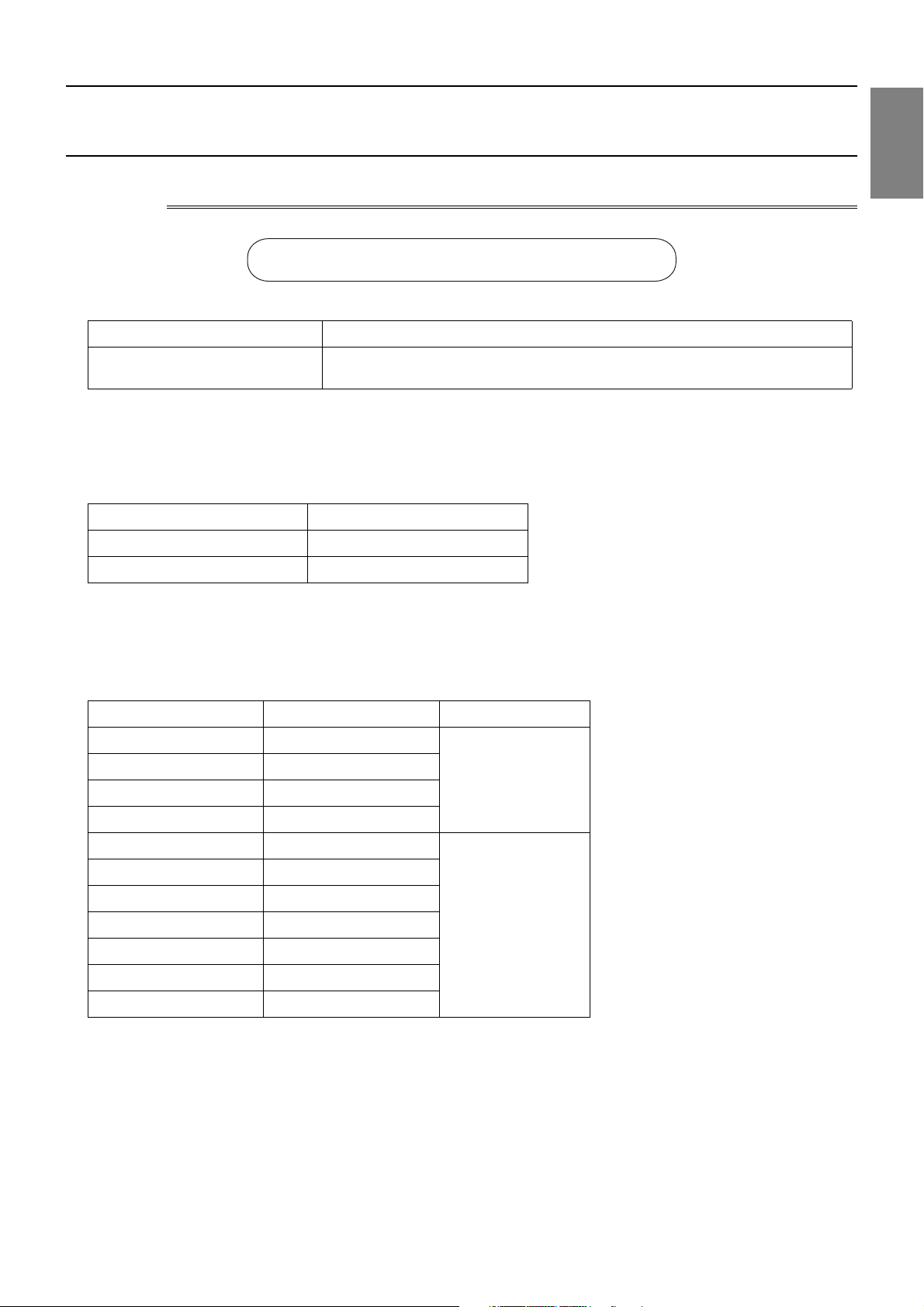
1-1-1 Read before Servicing
1. Check the type of refrigerant used in the system to be serviced.
Refrigerant Type
Multi air conditioner for building application CITY MULTI YKM-A series R410A
2. Check the symptoms exhibited by the unit to be serviced.
Refer to this service handbook for symptoms relating to the refrigerant cycle.
3. Thoroughly read the safety precautions at the beginning of this manual.
4. Preparing necessary tools: Prepare a set of tools to be used exclusively with each type of refrigerant.
For information about the correct use of tools, refer to the following page(s). [1-1-2 Tool Preparation](page 4)
5. Verification of the connecting pipes: Verify the type of refrigerant used for the unit to be moved or replaced.
Use refrigerant pipes made of phosphorus deoxidized copper. Keep the inner and outer surfaces of the pipes clean and free
of such contaminants as sulfur, oxides, dust, dirt, shaving particles, oil, and water.
These types of contaminants inside the refrigerant pipes may cause the refrigerant oil to deteriorate.
6. If there is a leak of gaseous refrigerant and the remaining refrigerant is exposed to an open flame, a poisonous gas
hydrofluoric acid may form. Keep workplace well ventilated.
1 Piping Work
Install new pipes immediately after removing old ones to keep moisture out of the refrigerant circuit.
The use of refrigerant that contains chloride, such as R22, will cause the refrigerating machine oil to deteriorate.
HWE12050 GB
- 3 -
Page 13
[1-1 Preparation for Piping Work ]
1-1-2 Tool Preparation
Prepare the following tools and materials necessary for installing and servicing the unit.
Tools for use with R410A (Adaptability of tools that are for use with R22 or R407C)
1. To be used exclusively with R410A (not to be used if used with R22 or R407C)
Tools/Materials Use Notes
Gauge Manifold Evacuation and refrigerant charging Higher than 5.09MPa[738psi] on the
Charging Hose Evacuation and refrigerant charging The hose diameter is larger than the
Refrigerant Recovery Cylinder Refrigerant recovery
Refrigerant Cylinder Refrigerant charging The refrigerant type is indicated. The
Charging Port on the Refrigerant Cylinder Refrigerant charging The charge port diameter is larger
Flare Nut Connection of the unit with the pipes Use Type-2 Flare nuts.
2. Tools and materials that may be used with R410A with some restrictions
Tools/Materials Use Notes
Gas Leak Detector Gas leak detection The ones for use with HFC refrigerant
Vacuum Pump Vacuum drying May be used if a check valve adapter
Flare Tool Flare processing Flare processing dimensions for the
high-pressure side
conventional model.
cylinder is pink.
than that of the current port.
may be used.
is attached.
piping in the system using the new refrigerant differ from those of R22. Refer to the following page(s). [1-2-1
Piping Materials](page 5)
Refrigerant Recovery Equipment Refrigerant recovery May be used if compatible with
3. Tools and materials that are used with R22 or R407C that may also be used with R410A
Tools/Materials Use Notes
Vacuum Pump with a Check Valve Vacuum drying
Bender Bending pipes
Torque Wrench Tightening flare nuts Only the flare processing dimensions
Pipe Cutter Cutting pipes
Welder and Nitrogen Cylinder Welding pipes
Refrigerant Charging Meter Refrigerant charging
Vacuum Gauge Vacuum level check
4. Tools and materials that must not be used with R410A
Tools/Materials Use Notes
Charging Cylinder Refrigerant charging Prohibited to use
R410A.
for pipes that have a diameter of
ø12.7 (1/2") and ø15.88 (5/8") have
been changed.
Tools for R410A must be handled with special care to keep moisture and dust from infiltrating the cycle.
HWE12050 GB
- 4 -
Page 14
[1-2 Handling and Characteristics of Piping Materials, Refrigerant, and Refrigerant Oil ]
1-2 Handling and Characteristics of Piping Materials,
Refrigerant, and Refrigerant Oil
1-2-1 Piping Materials
Do not use the existing piping!
1. Copper pipe materials
O-material (Annealed) Soft copper pipes (annealed copper pipes). They can easily be bent with hands.
1/2H-material (Drawn) Hard copper pipes (straight pipes). They are stronger than the O-material (Annealed)
at the same radial thickness.
The distinction between O-materials (Annealed) and 1/2H-materials (Drawn) is made based on the strength of the pipes them-
selves.
O-materials (Annealed) can easily be bent with hands.
1/2H-materials (Drawn) are considerably stronger than O-material (Annealed) at the same thickness.
2. Types of copper pipes
Maximum working pressure Refrigerant type
3.45 MPa [500psi] R22, R407C etc.
4.30 MPa [624psi] R410A etc.
3. Piping materials/Radial thickness
Use refrigerant pipes made of phosphorus deoxidized copper.
The operation pressure of the units that use R410A is higher than that of the units that use R22.
Use pipes that have at least the radial thickness specified in the chart below.
(Pipes with a radial thickness of 0.7 mm or less may not be used.)
Pipe size (mm[in]) Radial thickness (mm) Type
ø6.35 [1/4"] 0.8t
1 Piping Work
ø9.52 [3/8"] 0.8t
ø12.7 [1/2"] 0.8t
ø15.88 [5/8"] 1.0t
ø19.05 [3/4"] 1.0t
ø22.2 [7/8"] 1.0t
ø25.4 [1"] 1.0t
ø28.58 [1-1/8"] 1.0t
ø31.75 [1-1/4"] 1.1t
ø34.93 [1-3/8"] 1.1t
ø41.28 [1-5/8"] 1.2t
The pipes in the system that uses the refrigerant currently on the market are made with O-material (Annealed), even if the
pipe diameter is less than ø19.05 (3/4"). For a system that uses R410A, use pipes that are made with 1/2H-material (Drawn)
unless the pipe diameter is at least ø19.05 (3/4") and the radial thickness is at least 1.2t.
The figures in the radial thickness column are based on the Japanese standards and provided only as a reference. Use pipes
that meet the local standards.
O-material (Annealed)
1/2H-material,
H-material (Drawn)
HWE12050 GB
- 5 -
Page 15
[1-2 Handling and Characteristics of Piping Materials, Refrigerant, and Refrigerant Oil ]
Dimension A
Dimension B
4. Thickness and refrigerant type indicated on the piping materials
Ask the pipe manufacturer for the symbols indicated on the piping material for new refrigerant.
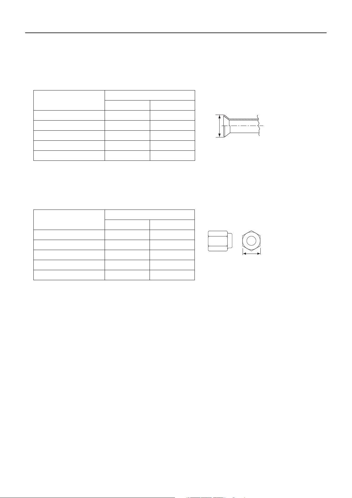
5. Flare processing (O-material (Annealed) and OL-material only)
The flare processing dimensions for the pipes that are used in the R410A system are larger than those in the R22 system.
Flare processing dimensions (mm[in])
A dimension (mm)
Pipe size (mm[in])
R410A R22, R407C
ø6.35 [1/4"] 9.1 9.0
ø9.52 [3/8"] 13.2 13.0
ø12.7 [1/2"] 16.6 16.2
ø15.88 [5/8"] 19.7 19.4
ø19.05 [3/4"] 24.0 23.3
If a clutch-type flare tool is used to flare the pipes in the system using R410A, the length of the pipes must be between 1.0
and 1.5 mm. For margin adjustment, a copper pipe gauge is necessary.
6. Flare nut
The flare nut type has been changed to increase the strength. The size of some of the flare nuts have also been changed.
Flare nut dimensions (mm[in])
B dimension (mm)
Pipe size (mm[in])
R410A R22, R407C
ø6.35 [1/4"] 17.0 17.0
ø9.52 [3/8"] 22.0 22.0
ø12.7 [1/2"] 26.0 24.0
ø15.88 [5/8"] 29.0 27.0
ø19.05 [3/4"] 36.0 36.0
The figures in the radial thickness column are based on the Japanese standards and provided only as a reference. Use pipes
that meet the local standards.
HWE12050 GB
- 6 -
Page 16
[1-2 Handling and Characteristics of Piping Materials, Refrigerant, and Refrigerant Oil ]
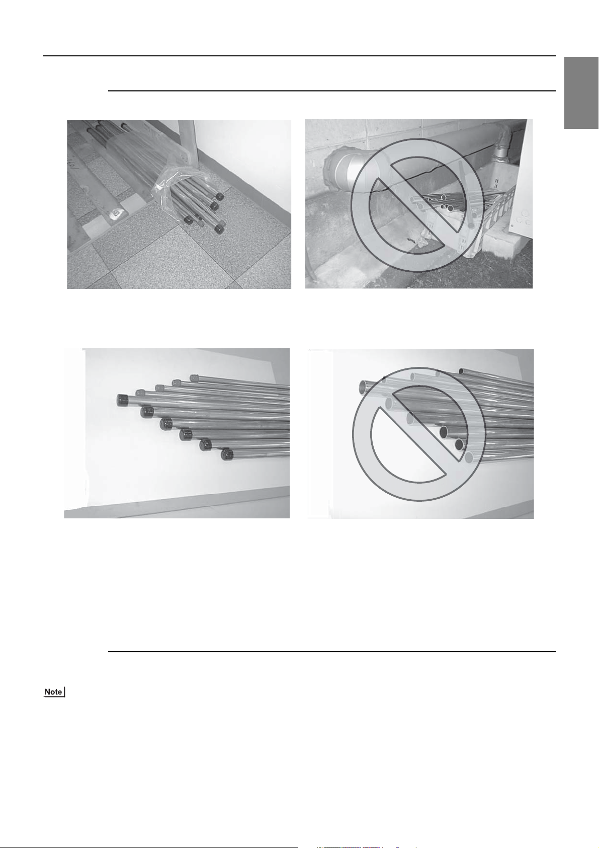
1-2-2 Storage of Piping Materials
1. Storage location
Store the pipes to be used indoors. (Warehouse at site or owner's warehouse)
If they are left outdoors, dust, dirt, or moisture may infiltrate and contaminate the pipe.
1 Piping Work
2. Sealing the pipe ends
Both ends of the pipes should be sealed until just before brazing.
Keep elbow pipes and T-joints in plastic bags.
The new refrigerator oil is 10 times as hygroscopic as the conventional refrigerating machine oil (such as Suniso) and, if not
handled with care, could easily introduce moisture into the system. Keep moisture out of the pipes, for it will cause the oil to
deteriorate and cause a compressor failure.
1-2-3 Pipe Processing
Use a small amount of ester oil, ether oil, or alkylbenzene to coat flares and flanges.
Use a minimum amount of oil.
Use only ester oil, ether oil, and alkylbenzene.
HWE12050 GB
- 7 -
Page 17

[1-2 Handling and Characteristics of Piping Materials, Refrigerant, and Refrigerant Oil ]
1-2-4 Characteristics of the New and Conventional Refrigerants
1. Chemical property
As with R22, the new refrigerant (R410A) is low in toxicity and chemically stable nonflammable refrigerant.
However, because the specific gravity of vapor refrigerant is greater than that of air, leaked refrigerant in a closed room will
accumulate at the bottom of the room and may cause hypoxia.
If exposed to an open flame, refrigerant will generate poisonous gases. Do not perform installation or service work in a confined area.
New Refrigerant (HFC type) Conventional Refriger-
ant (HCFC type)
R410A R407C R22
R32/R125 R32/R125/R134a R22
Composition (wt%) (50/50) (23/25/52) (100)
Type of Refrigerant Pseudo-azeotropic
Refrigerant
Chloride Not included Not included Included
Safety Class A1/A1 A1/A1 A1
Molecular Weight 72.6 86.2 86.5
Boiling Point (°C/°F) -51.4/-60.5 -43.6/-46.4 -40.8/-41.4
Steam Pressure
1.557/226 0.9177/133 0.94/136
(25°C,MPa/77°F,psi) (gauge)
Saturated Steam Density
64.0 42.5 44.4
(25°C,kg/m3/77°F,psi)
Non-azeotropic
Refrigerant
Single Refrigerant
Flammability Nonflammable Nonflammable Nonflammable
Ozone Depletion Coefficient (ODP)
Global Warming Coefficient (GWP)
*1
*2
Refrigerant Charging Method Refrigerant charging in
Replenishment of Refrigerant after a Refrigerant
0 0 0.055
1730 1530 1700
the liquid state
Refrigerant charging in
the liquid state
Refrigerant charging in
the gaseous state
Available Available Available
Leak
*1 When CFC11 is used as a reference
*2 When CO2 is used as a reference
2. Refrigerant composition
R410A is a pseudo-azeotropic HFC blend and can almost be handled the same way as a single refrigerant, such as R22. To
be safe, however, draw out the refrigerant from the cylinder in the liquid phase. If the refrigerant in the gaseous phase is drawn
out, the composition of the remaining refrigerant will change and become unsuitable for use.
If the refrigerant leaks out, it may be replenished. The entire refrigerant does not need to be replaced.
3. Pressure characteristics
The pressure in the system using R410A is 1.6 times as great as that in the system using R22.
Pressure (gauge)
Temperature (°C/°F)
R410A R407C R22
MPa/psi MPa/psi MPa/psi
-20/-4 0.30/44 0.18/26 0.14/20
0/32 0.70/102 0.47/68 0.40/58
20/68 1.34/194 0.94/136 0.81/117
40/104 2.31/335 1.44/209 1.44/209
60/140 3.73/541 2.44/354 2.33/338
65/149 4.17/605 2.75/399 2.60/377
HWE12050 GB
- 8 -
Page 18
[1-2 Handling and Characteristics of Piping Materials, Refrigerant, and Refrigerant Oil ]
1-2-5 Refrigerant Oil
1. Refrigerating machine oil in the HFC refrigerant system
HFC type refrigerants use a refrigerating machine oil different from that used in the R22 system.
Note that the ester oil used in the system has properties that are different from commercially available ester oil.
Refrigerant Refrigerating machine oil
R22 Mineral oil
R407C Ester oil
R410A Ester oil
2. Effects of contaminants
*1
Refrigerating machine oil used in the HFC system must be handled with special care to keep contaminants out.
The table below shows the effect of contaminants in the refrigerating machine oil on the refrigeration cycle.
3. The effects of contaminants in the refrigerating machine oil on the refrigeration cycle.
Cause Symptoms Effects on the refrigerant cycle
Water infiltration Frozen expansion valve
and capillary tubes
Clogged expansion valve and capillary tubes
Poor cooling performance
Compressor overheat
Motor insulation failure
Burnt motor
Coppering of the orbiting scroll
Lock
Burn-in on the orbiting scroll
Hydrolysis
Sludge formation and adhesion
Acid generation
Oxidization
Oil degradation
Air infiltration Oxidization
Adhesion to expansion valve and capillary
tubes
Clogged expansion valve, capillary tubes, and
drier
Poor cooling performance
Infiltration of
contaminants
Dust, dirt
Infiltration of contaminants into the compressor
Compressor overheat
Burn-in on the orbiting scroll
Sludge formation and adhesion Clogged expansion valve and capillary tubes
Mineral oil
etc.
Poor cooling performance
Compressor overheat
Oil degradation Burn-in on the orbiting scroll
1 Piping Work
*1. Contaminants is defined as moisture, air, processing oil, dust/dirt, wrong types of refrigerant, and refrigerating machine oil.
HWE12050 GB
- 9 -
Page 19
[1-3 Working with Refrigerant Piping ]
1-3 Working with Refrigerant Piping
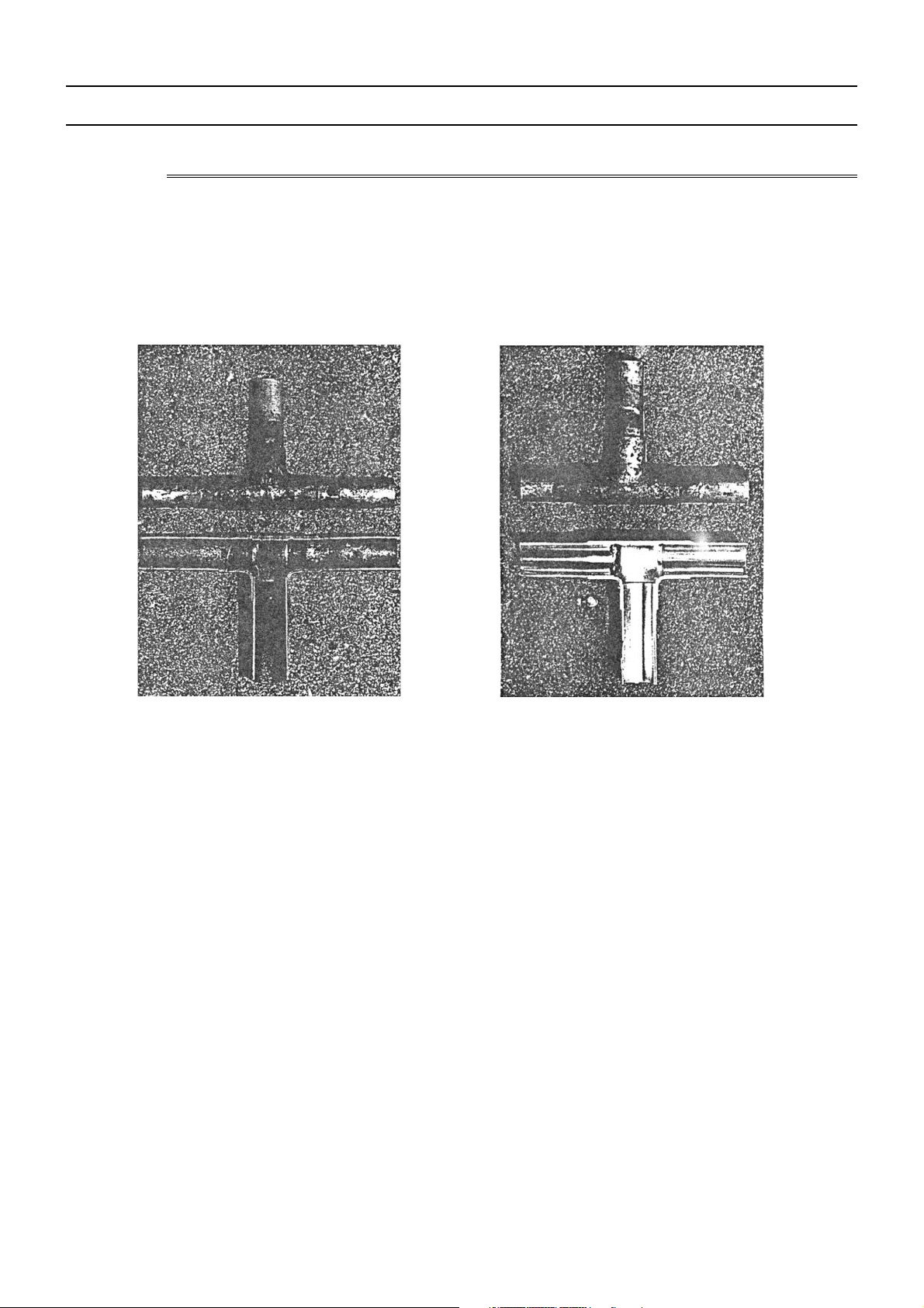
1-3-1 Pipe Brazing
No changes have been made in the brazing procedures. Perform brazing with special care to keep foreign objects (such as oxide
scale, water, and dust) out of the refrigerant system.
Example: Inside the brazed connection
Use of oxidized solder for brazing Use of non-oxidized solder for brazing
1. Items to be strictly observed
Do not conduct refrigerant piping work outdoors if raining.
Use non-oxidized solder.
Use a brazing material (BCuP-3) that requires no flux when brazing between copper pipes or between a copper pipe and
copper coupling.
If installed refrigerant pipes are not immediately connected to the equipment, then braze and seal both ends.
2. Reasons
The new refrigerating machine oil is 10 times as hygroscopic as the conventional oil and is more likely to cause unit failure if
water infiltrates into the system.
Flux generally contains chloride. Residual flux in the refrigerant circuit will cause sludge to form.
3. Notes
Do not use commercially available antioxidants because they may cause the pipes to corrode or refrigerating machine oil to
deteriorate.
HWE12050 GB
- 10 -
Page 20
[1-3 Working with Refrigerant Piping ]
1-3-2 Air Tightness Test
No changes have been made in the detection method. Note that a refrigerant leak detector for R22 will not detect an R410A leak.
1 Piping Work
Halide torch R22 leakage detector
1. Items to be strictly observed
Pressurize the equipment with nitrogen up to the design pressure (4.15MPa[601psi]), and then judge the equipment's air tight-
ness, taking temperature variations into account.
Refrigerant R410A must be charged in its liquid state (vs. gaseous state).
2. Reasons
Oxygen, if used for an air tightness test, poses a risk of explosion. (Only use nitrogen to check air tightness.)
Refrigerant R410A must be charged in its liquid state. If gaseous refrigerant in the cylinder is drawn out first, the composition
of the remaining refrigerant in the cylinder will change and become unsuitable for use.
3. Notes
Procure a leak detector that is specifically designed to detect an HFC leak. A leak detector for R22 will not detect an
HFC(R410A) leak.
HWE12050 GB
- 11 -
Page 21
[1-3 Working with Refrigerant Piping ]
1-3-3 Vacuum Drying
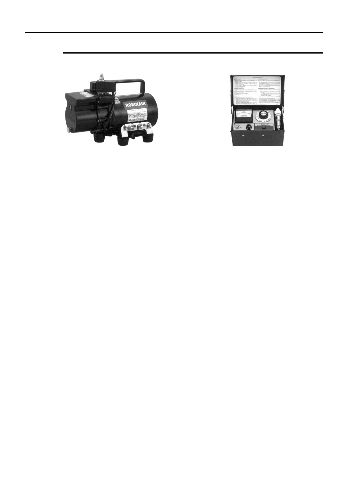
(Photo1) 15010H (Photo2) 14010
Recommended vacuum gauge:
ROBINAIR 14010 Thermistor Vacuum Gauge
1. Vacuum pump with a reverse-flow check valve (Photo1)
To prevent the vacuum pump oil from flowing into the refrigerant circuit during power OFF or power failure, use a vacuum
pump with a reverse-flow check valve.
A reverse-flow check valve may also be added to the vacuum pump currently in use.
2. Standard of vacuum degree (Photo 2)
Use a vacuum pump that attains 0.5Torr(65Pa) or lower degree of vacuum after 5 minutes of operation, and connect it directly
to the vacuum gauge. Use a pump well-maintained with an appropriate lubricant. A poorly maintained vacuum pump may not
be able to attain the desired degree of vacuum.
3. Required precision of vacuum gauge
Use a vacuum gauge that registers a vacuum degree of 5Torr(650Pa) and measures at intervals of 1Torr(130Pa). (A recommended vacuum gauge is shown in Photo2.)
Do not use a commonly used gauge manifold because it cannot register a vacuum degree of 5Torr(650Pa).
4. Evacuation time
After the degree of vacuum has reached 5Torr(650Pa), evacuate for an additional 1 hour. (A thorough vacuum drying re-
moves moisture in the pipes.)
Verify that the vacuum degree has not risen by more than 1Torr(130Pa) 1hour after evacuation. A rise by less than
1Torr(130Pa) is acceptable.
If the vacuum is lost by more than 1Torr(130Pa), conduct evacuation, following the instructions in section 6. Special vacuum
drying.
5. Procedures for stopping vacuum pump
To prevent the reverse flow of vacuum pump oil, open the relief valve on the vacuum pump side, or draw in air by loosening
the charge hose, and then stop the operation.
The same procedures should be followed when stopping a vacuum pump with a reverse-flow check valve.
6. Special vacuum drying
When 5Torr(650Pa) or lower degree of vacuum cannot be attained after 3 hours of evacuation, it is likely that water has pen-
etrated the system or that there is a leak.
If water infiltrates the system, break the vacuum with nitrogen. Pressurize the system with nitrogen gas to
0.5kgf/cm
2
G(0.05MPa) and evacuate again. Repeat this cycle of pressurizing and evacuation either until the degree of vac-
uum below 5Torr(650Pa) is attained or until the pressure stops rising.
Only use nitrogen gas for vacuum breaking. (The use of oxygen may result in an explosion.)
HWE12050 GB
- 12 -
Page 22
[1-3 Working with Refrigerant Piping ]
1-3-4 Refrigerant Charging
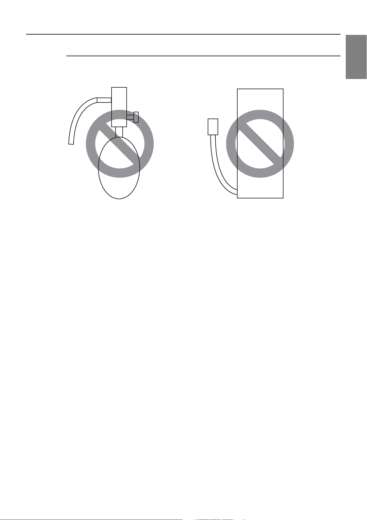
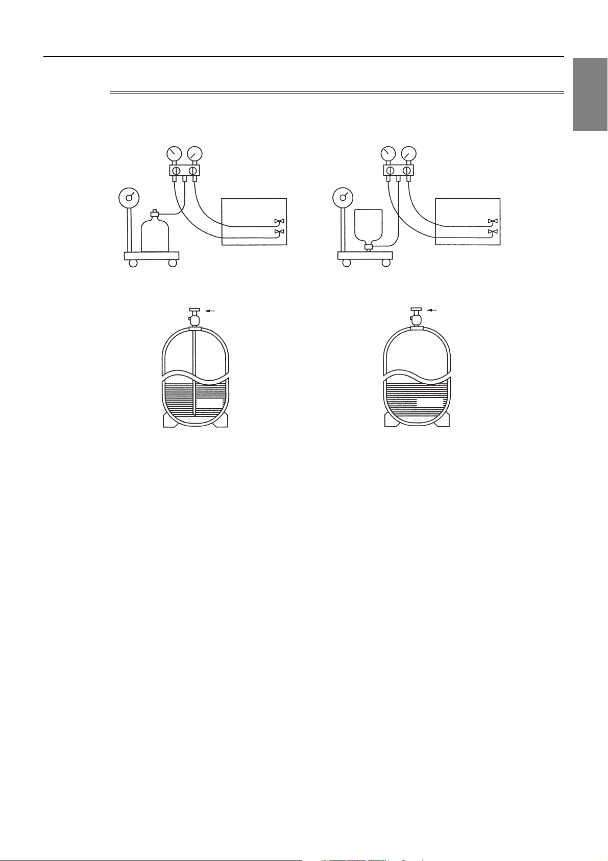
Cylinder with a siphon
Cylinder without a siphon
Cylin-
Cylin-
der
der
Cylinder color R410A is pink. Refrigerant charging in the liquid state
Valve Valve
liquid
liquid
1 Piping Work
1. Reasons
R410A is a pseudo-azeotropic HFC blend (boiling point R32=-52°C[-62°F], R125=-49°C[-52°F]) and can almost be handled
the same way as a single refrigerant, such as R22. To be safe, however, draw out the refrigerant from the cylinder in the liquid
phase. If the refrigerant in the gaseous phase is drawn out, the composition of the remaining refrigerant will change and become unsuitable for use.
2. Notes
When using a cylinder with a siphon, refrigerant is charged in the liquid state without the need for turning it upside down. Check
the type of the cylinder on the label before use.
If the refrigerant leaks out, it may be replenished. The entire refrigerant does not need to be replaced. (Charge refrigerant in
the liquid state.)
Refer to the following page(s).[8-11 Measures for Refrigerant Leakage](page 246)
HWE12050 GB
- 13 -
Page 23

[1-3 Working with Refrigerant Piping ]
HWE12050 GB
- 14 -
Page 24

Chapter 2 Restrictions
2-1 System Configurations....................................................................................................................... 17
2-2 Types and Maximum Allowable Length of Cables........................................................................... 18
2-3 Switch Settings ................................................................................................................................... 19
2-4 M-NET Address Settings .................................................................................................................... 20
2-4-1 Address Settings List ............................................................................................................................ 20
2-4-2 Outdoor Unit Power Jumper Connector Connection.............................................................................21
2-4-3 Outdoor Unit Centralized Controller Switch Setting .............................................................................. 21
2-4-4 Room Temperature Detection Position Selection ................................................................................. 21
2-4-5 Start/Stop Control of Indoor Units ......................................................................................................... 22
2-4-6 Miscellaneous Settings ......................................................................................................................... 22
2-4-7 Various Control Methods Using the Signal Input/Output Connector on Outdoor Unit .......................... 23
2-5 Demand Control Overview ................................................................................................................. 26
2-6 System Connection Example............................................................................................................. 28
2-7 Example System with an MA Remote Controller ............................................................................. 30
2-7-1 Single Refrigerant System (Automatic Indoor/Outdoor Address Startup) ............................................. 30
2-7-2 Single Refrigerant System with Two or More LOSSNAY Units ............................................................ 32
2-7-3 Grouped Operation of Units in Separate Refrigerant Circuits ............................................................... 34
2-7-4 System with a Connection of System Controller to Centralized Control Transmission Line ................. 36
2-7-5 System with a Connection of System Controller to Indoor-Outdoor Transmission Line ....................... 38
2-8 Example System with an ME Remote Controller ............................................................................. 40
2-8-1 System with a Connection of System Controller to Centralized Control Transmission Line ................. 40
2-9 Example System with an MA and an ME Remote Controller .......................................................... 42
2-9-1 System with a Connection of System Controller to Centralized Control Transmission Line ................. 42
2-10 Restrictions on Refrigerant Pipes ..................................................................................................... 44
2-10-1 Restrictions on Refrigerant Pipe Length ............................................................................................... 44
2-10-2 Restrictions on Refrigerant Pipe Size ................................................................................................... 46
HWE12050 GB
- 15 -
Page 25

HWE12050 GB
- 16 -
Page 26
[2-1 System Configurations ]
2 Restrictions
2-1 System Configurations
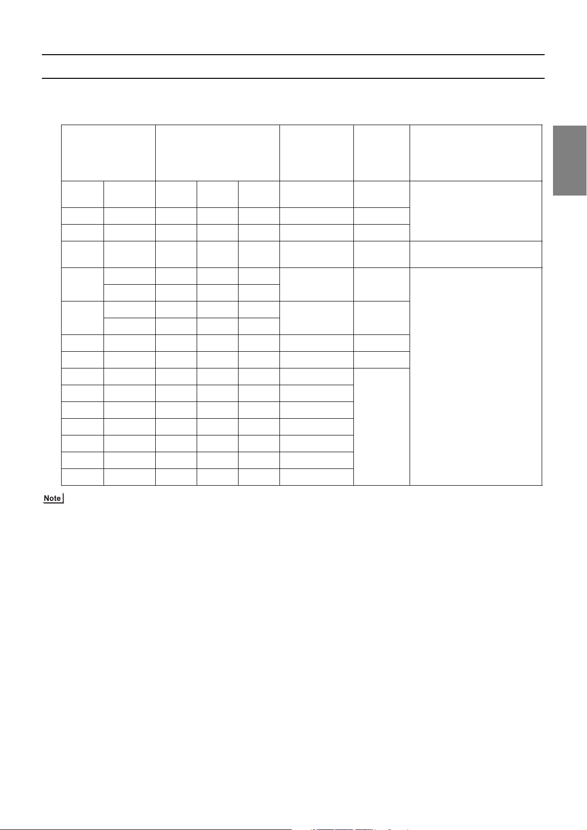
1. Table of compatible indoor units
(1) High COP combinations
The table below summarizes the types of indoor units that are compatible with different types of outdoor units.
Outdoor units Composing units Maximum total
capacity of con-
nectable indoor
units
Maximum
number of
connect-
able indoor
units
EP200 YKM-A - - - 100 - 260 17
EP250 YKM-A - - - 125 - 325 21
EP300 YKM-A - - - 150 - 390 26
EP350 YKM-A - - - 175 - 455 30
YKM-A - - -
EP400
200 - 520 34
YSKM-A EP200 EP200 -
YKM-A - - -
EP450
225 - 585 39
YSKM-A EP250 EP200 -
EP500 YSKM-A EP300 EP200 - 250 - 650 43
EP550 YSKM-A EP300 EP250 - 275 - 715 47
EP600 YSKM-A EP300 EP300 - 300 - 780 50
EP650 YSKM-A EP250 EP200 EP200 325 - 845
EP700 YSKM-A EP300 EP200 EP200 350 - 910
EP750 YSKM-A EP300 EP250 EP200 375 - 975
EP800 YSKM-A EP300 EP300 EP200 400 - 1040
Types of connectable
indoor units
P15 - P200 models
R410A series indoor units
P15 - P400 models
R410A series indoor units
2 Restrictions
P15 - P500 models
R410A series indoor units
EP850 YSKM-A EP300 EP300 EP250 425 - 1105
EP900 YSKM-A EP300 EP300 EP300 450 - 1170
1) "Maximum total capacity of connectable indoor units" refers to the sum of the numeric values in the indoor unit model names.
2) If the total capacity of the indoor units that are connected to a given outdoor unit exceeds the capacity of the outdoor unit, the
indoor units will not be able to perform at the rated capacity when they are operated simultaneously. Select a combination of
units so that the total capacity of the connected indoor units is at or below the capacity of the outdoor unit whenever possible.
HWE12050 GB
- 17 -
Page 27
[2-2 Types and Maximum Allowable Length of Cables ]
TB 3 TB 7 TB 3 TB
7
TB
3
TB 3 TB
7
TB
7
TB 3 TB
7
TB
3
TB
7
TB 3 TB 7 TB 3 TB
7
TB
3
TB 3 TB
7
TB
7
TB 3 TB
7
TB
3
TB
7
2-core shielded cable
2-core shielded cable
Indoor unit
Outdoor unit
TB3: Terminal block for indoor-outdoor transmission line TB7: Terminal block for centralized control
Remote Controller
Indoor unit
Outdoor unit
Remote Controller
multiple-core cable
2-2 Types and Maximum Allowable Length of Cables
1. Wiring work
(1) Notes
1) Have all electrical work performed by an authorized electrician according to the local regulations and instructions in this manual.
2) Install external transmission cables at least 5cm [1-31/32"] away from the power supply cable to avoid noise interference.
(Do not put the control cable and power supply cable in the same conduit tube.)
3) Provide grounding for the outdoor unit as required.
4) Run the cable from the electric box of the indoor or outdoor unit in such way that the box is accessible for servicing.
5) Do not connect power supply wiring to the terminal block for transmission line. Doing so will damage the electronic components on the terminal block.
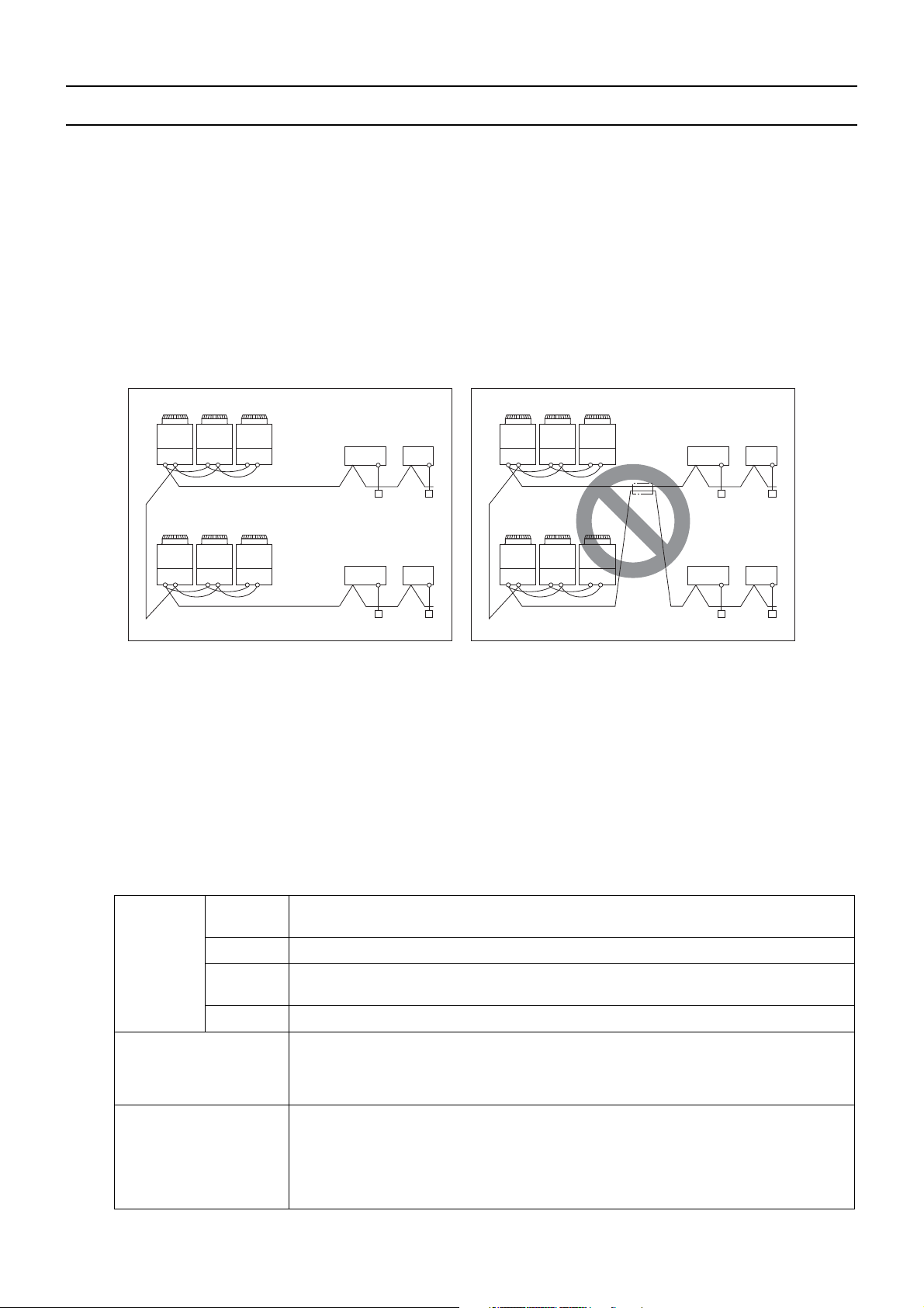
6) Use 2-core shielded cables as transmission cables.
Use a separate 2-core control cable for each refrigerant system. Do not use a single multiple-core cable to connect indoor
units that belong to different refrigerant systems. The use of a multiple-core cable may result in signal transmission errors and
malfunctions.
7) When extending the transmission cable, be sure to extend the shield wire.
(2) Control wiring
Different types of control wiring are used for different systems. Before performing wiring work, refer to the following page(s).
[2-7 Example System with an MA Remote Controller](page 30)
[2-8 Example System with an ME Remote Controller](page 40)
[2-9 Example System with an MA and an ME Remote Controller](page 42)
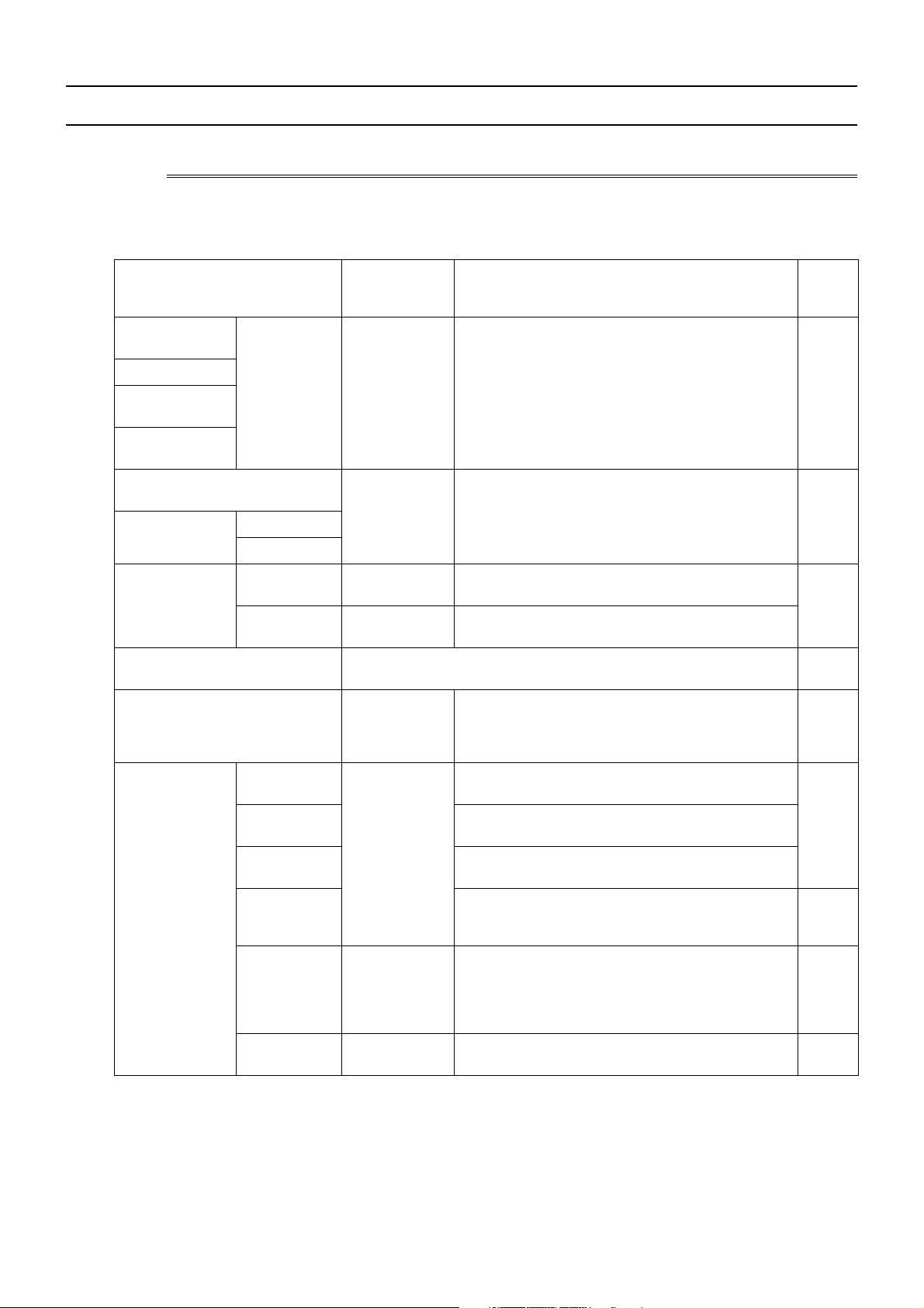
Types and maximum allowable length of cables
Control lines are categorized into 2 types: transmission line and remote controller line.
Use the appropriate type of cables and observe the maximum allowable length specified for a given system. If a given system
has a long transmission line or if a noise source is located near the unit, place the unit away from the noise source to reduce
noise interference.
1) M-NET transmission line
Facility
type
Type Shielded cable CVVS, CPEVS, MVVS
Cable type
Number of
cores
Cable size Larger than 1.25mm2 [AWG16]
Maximum transmission
line distance between the
outdoor unit and the farthest indoor unit
Maximum transmission
line distance for centralized control and Indoor/
outdoor transmission line
(Maximum line distance
500 m [1640ft] max.
*The maximum overall line length from the power supply unit on the transmission lines for
centralized control to each outdoor unit or to the system controller is 200m [656ft] max.
via outdoor unit)
All facility types
2-core cable
200 m [656ft] max.
HWE12050 GB
- 18 -
Page 28

[2-3 Switch Settings ]
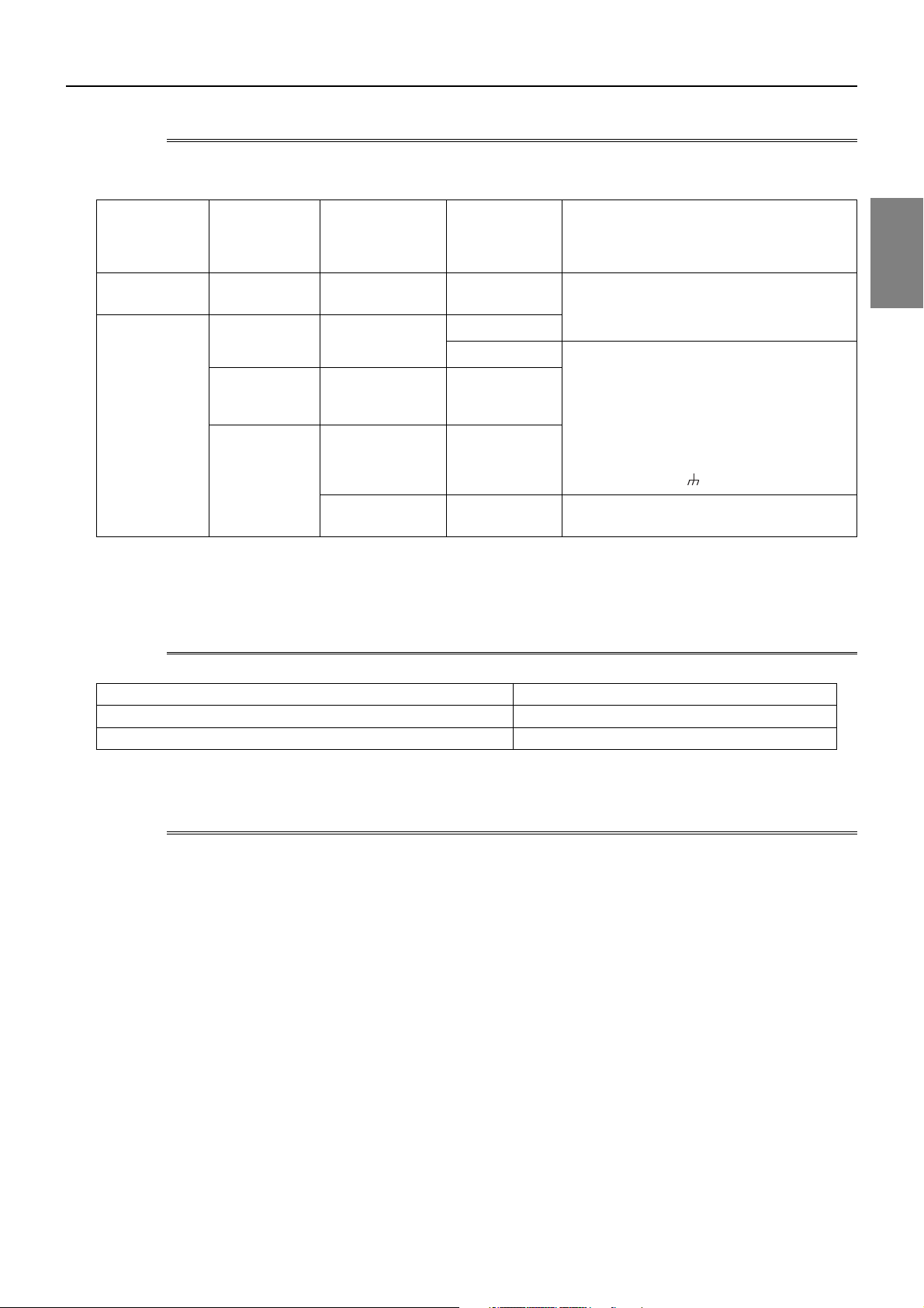
2) Remote controller wiring
Type CVV CVV
Number of
cores
Cable type
Cable size
Maximum overall line
length
*1 MA remote controller refers to MA remote controller (PAR-31MAA, PAR-21MAA), MA simple remote controller, and
wireless remote controller.
*2 ME remote controller refers to ME remote controller and ME simple remote controller.
*3 The use of cables that are smaller than 0.75mm
*4 When connected to the terminal block on the Simple remote controller, use cables that meet the cable size specifi-
cations shown in the parenthesis.
*5 When connecting PAR-31MAA or MA Simple remote controller, use sheathed cables with a minimum thickness of
0.3 mm
2
.
MA remote controller
*1
2-core cable 2-core cable
0.3 to 1.25mm
[AWG22 to 16]
(0.75 to 1.25mm2 )
0.3 to 1.25mm
[AWG22 to 16]
2 *3 *5
[AWG18 to 16]
The section of the cable that exceeds 10m
200 m [656ft] max.
[32ft] must be included in the maximum indoor-outdoor transmission line distance.
2
(AWG18) is recommended for easy handling.
ME remote controller
2 *3
*4
*2
2 Restrictions
2-3 Switch Settings
1. Switch setting
The necessary switch settings depend on system configuration. Before performing wiring work, refer to the following page(s).
[2-7 Example System with an MA Remote Controller](page 30)
[2-8 Example System with an ME Remote Controller](page 40)
[2-9 Example System with an MA and an ME Remote Controller](page 42)
If the switch settings are changed while the unit is being powered, those changes will not take effect, and the unit will not
function properly.
Units on which to set the switches Symbol Units to which the power must be shut off
*3
CITY MULTI indoor unit Main/sub unit IC Outdoor units
LOSSNAY, OA processing unit
*1
LC Outdoor units
ATW Booster Unit BU Outdoor units and Booster Unit
Water Hex Unit AU Outdoor units and Water Hex Unit
Air handling kit IC Outdoor units
unit
ME remote controller Main/sub remote
RC Outdoor units
controller
MA remote controller
*4
Main/sub remote
MA Indoor units
controller
CITY MULTI outdoor unit
*2
OC,OS1,OS2 Outdoor units
*1. Applicable when LOSSNAY units are connected to the indoor-outdoor transmission line.
*2. The outdoor units in the same refrigerant circuit are automatically designated as OC, OS1, and OS2 in the order of
capacity from large to small (if two or more units have the same capacity, in the order of address from small to large).
*3. Turn off the power to all the outdoor units in the same refrigerant circuit.
*4. When a PAR-31MAA is connected to a group, no other MA remote controllers can be connected to the same group.
*5. When setting the switch SW4 of the control board, set it with the outdoor unit power on. Refer to the following page(s).
[5-1-1 Outdoor Unit Switch Functions and Factory Settings](page 77)
and Indoor units
*3
and LOSSNAY
*3
or field supplied air handling
*3
*3 *5
HWE12050 GB
- 19 -
Page 29
[2-4 M-NET Address Settings ]
2-4 M-NET Address Settings
2-4-1 Address Settings List
1. M-NET Address settings
(1) Address settings table
The need for address settings and the range of address setting depend on the configuration of the system.
Unit or controller Address setting
Setting method Facto-
range
CITY MULTI indoor unit
Main/sub unit 00,
01 to 50
*1*6
Assign the smallest address to the main indoor unit in the
group, and assign sequential address numbers to the rest
of the indoor units in the same group.
*4
M-NET adapter
M-NET control interface
Free Plan adapter
LOSSNAY, OA processing unit
Air handling kit
ATW Booster Unit
00,
01 to 50
*1*6
Assign an arbitrary but unique address to each of
these units after assigning an address to all indoor
units.
Water Hex Unit
ME remote controller
MA remote controller No address settings required. (The main/sub setting must be made if 2
CITY MULTI outdoor unit 00,
Main remote
controller
Sub remote
controller
101 to 150 Add 100 to the smallest address of all the indoor units
in the same group.
*2
151 to 200
Add 150 to the smallest address of all the indoor units
in the same group.
remote controllers are connected to the system.)
Assign sequential addresses to the outdoor units in the
same refrigerant circuit. The outdoor units in the same
refrigerant circuit are automatically designated as OC
and OS.
*5
51 to 100
*1,*3,*6
*7
ry set-
ting
00
00
101
Main
00
System controller Group remote
controller
System remote
controller
ON/OFF remote controller
Schedule timer
(compatible
201 to 250 Assign an address that equals the sum of the smallest
group number of the group to be controlled and 200.
Assign an arbitrary but unique address within the
range listed on the left to each unit.
Assign an address that equals the sum of the smallest
group number of the group to be controlled and 200.
Assign an arbitrary but unique address within the
range listed on the left to each unit.
201
202
with M-NET)
Central controller
AG-150A
000,
201 to 250
Assign an arbitrary but unique address within the
range listed on the left to each unit. The address must
be set to "000" to control the K-control unit.
000
GB-50ADA
G(B)-50A
LM adapter 201 to 250 Assign an arbitrary but unique address within the
247
range listed on the left to each unit.
*1. Address setting is not required for a City Multi system that consists of a single refrigerant circuit (with some exceptions).
*2. To set the ME remote controller address to "200", set the rotary switches to "00".
*3. To set the outdoor unit address to "100," set the rotary switches to "50."
*4. Some indoor units have 2 or 3 controller boards that require address settings.
No. 2 controller board address must be equal to the sum of the No. 1 controller board address and 1, and the No.3
controller board address must equal to the No. 1 controller address and 2.
*5. The outdoor units in the same refrigerant circuit are automatically designated as OC, OS1, and OS2 in the order of
capacity from large to small (if two or more units have the same capacity, in the order of address from small to large).
*6. If a given address overlaps any of the addresses that are assigned to other units, use a different, unused address within the
setting range.
*7. When a PAR-31MAA is connected to a group, no other MA remote controllers can be connected to the same group.
HWE12050 GB
- 20 -
Page 30
[2-4 M-NET Address Settings ]
2-4-2 Outdoor Unit Power Jumper Connector Connection
There are limitations on the total number of units that are connectable to each refrigerant system. Refer to the DATABOOK
for details.
System configuration
Connection to
the system controller
Power supply unit
for transmission
lines
Group operation
of units in a system with multiple
Power supply switch connector connection
outdoor units
System with
one outdoor unit
System with
multiple outdoor
units
_ _ _ Leave CN41 as it is
(Factory setting)
Not connected _ Not grouped
Grouped Disconnect the male connector from the fe-
With connection
to the indoor
unit system
With connection
to the centralized control
system
Not required Grouped/not
grouped
Not required
(Powered from the
*1
Grouped/not
grouped
outdoor unit)
Required *
1
Grouped/not
grouped
male power supply switch connector (CN41)
and connect it to the female power supply
switch connector (CN40) on only one of the
outdoor units.
*Connect the S (shielded) terminal on the ter-
minal block (TB7) on the outdoor unit whose
CN41 was replaced with CN40 to the
ground terminal ( ) on the electric box.
Leave CN41 as it is
(Factory setting)
*2
*1 The need for a power supply unit for transmission lines depends on the system configuration. Some controllers, such as
GB-50ADA, have a function to supply power to the transmission lines.
*2 The replacement of the power jumper connector from CN41 to CN40 must be performed on only one outdoor unit in the
system.
2-4-3 Outdoor Unit Centralized Controller Switch Setting
2 Restrictions
System configuration Centralized control switch (SW5-1) settings *
Connection to the system controller Not connected Leave it to OFF. (Factory setting)
Connection to the system controller Connected *
2
ON
*1 Set SW5-1 on all outdoor units in the same refrigerant circuit to the same setting.
*2 When only the LM adapter is connected, leave SW5-1 to OFF (as it is).
2-4-4 Room Temperature Detection Position Selection
To stop the fan during heating Thermo-OFF (SW1-7 and 1-8 on the indoor units to be set to ON), use the built-in thermistor
on the remote controller or an optional thermistor.
1) To use the built-in sensor on the remote controller, set the SW1-1 to ON.
(Factory setting: SW1-1 set to "OFF".)
Some models of remote controllers are not equipped with a built-in temperature sensor.
Use the built-in temperature sensor on the indoor unit instead.
When using the built-in sensor on the remote controller, install the remote controller where room temperature can be detected.
(Note) Factory setting for SW1-1 on the indoor unit of the All-Fresh Models is ON.
2) When an optional temperature sensor is used, set SW1-1 to OFF, and set SW3-8 to ON.
When using an optional temperature sensor, install it where room temperature can be detected.
1
HWE12050 GB
- 21 -
Page 31

[2-4 M-NET Address Settings ]
2-4-5 Start/Stop Control of Indoor Units
Each indoor unit (or group of indoor units) can be controlled individually by setting SW 1-9 and 1-10.
Function
Power ON/OFF by
the plug
*1,*2,*3
Automatic restoration
after power failure
Operation of the indoor unit when the operation is resumed after the unit was
stopped
Indoor unit will go into operation regardless of its operation status before power
off (power failure). (In approx. 5 minutes)
Indoor unit will go into operation if it was in operation when the power was
turned off (or cut off due to power failure). (In approx. 5 minutes)
Indoor unit will remain stopped regardless of its operation status before power
off (power failure).
*1. Do not cut off power to the outdoor unit. Cutting off the power supply to the outdoor unit will cut off the power supply to the
crankcase heater and may cause the compressor to malfunction when the unit is put back into operation.
*2. Not applicable to units with a built-in drain pump or humidifier.
*3. Models with a built-in drain pump cannot be turned on/off by the plug individually. All the units in the same refrigerant cir-
cuits will be turned on or off by the plug.
*4. Requires that the dipswitch settings for all the units in the group be made.
*5. To control the external input to and output from the air conditioners with the PLC software for general equipment via the
AG-150A, GB-50ADA, or G(B)-50A, set SW1-9 and SW1-10 to ON. With these settings made, the power start-stop func-
tion becomes disabled. To use the auto recovery function after power failure while these settings are made, set SW1-5 to
ON.
Setting (SW1)
910
OFF ON
ON OFF
OFF OFF
*4 *5
2-4-6 Miscellaneous Settings
Cooling-only setting for the indoor unit: Cooling only model (Factory setting: SW3-1 "OFF.")
When using indoor unit as a cooling-only unit, set SW3-1 to ON.
HWE12050 GB
- 22 -
Page 32

[2-4 M-NET Address Settings ]
2-4-7 Various Control Methods Using the Signal Input/Output Connector on Outdoor
Unit
(1) Various connection options
Type Usage Function
Input Prohibiting cooling/heating operation (thermo OFF) by an external
DEMAND (level) CN3D
input to the outdoor unit.
*It can be used as the DEMAND control device for each system.
Performs a low level noise operation of the outdoor unit by an external input to the outdoor unit.
Low-noise mode
*3*4
(level)
Terminal
to be
*1
used
*2
Option
Adapter for
external input
(PACSC36NA-E)
* It can be used as the silent operation device for each refrigerant
system.
Forces the outdoor unit to perform a fan operation by receiving signals from the snow sensor.
*5*7
Cooling/heating operation can be changed by an external input to
Snow sensor signal
CN3S
input (level)
Auto-changeover CN3N
the outdoor unit.
The operation mode of the unit can be changed from normal cooling operation (performance priority) to energy-saving cooling mode
Energy-saving
mode
CN3K
by an external signal input.
Out-
How to extract signals from the outdoor unit
put
*It can be used as an operation status display device.
*It can be used for an interlock operation with external devices.
Operation status of
the compressor
Error status
*5
*6
CN51 Adapter for
external output
(PACSC37SA-E)
*1 For details, refer to section (2) Example of wiring connection.
*2 For details, refer to section (2) Example of wiring connection and other relevant sections in the manual. [2-5 Demand Control
Overview](page 26)
*3 Low-noise mode is valid when Dip SW6-8 on the outdoor unit is set to OFF. When DIP SW6-8 is set to ON, 4 levels of on-
DEMAND are possible, using different configurations of low-noise mode input and DEMAND input settings.When 2 or more
outdoor units exist in one refrigerant circuit system, 8 levels of on-DEMAND are possible. When 3 outdoor units exist in one
refrigerant circuitsystem, 12 levels of on-DEMAND are possible.
*4 By setting Dip SW6-7, the Low-noise mode can be switched between the Capacity priority mode and the Low-noise priority
mode.
When SW6-7 is set to ON: The Low-noise mode always remains effective.
When SW6-7 is set to OFF: The Low-noise mode is cancelled when certain outside temperature or pressure criteria are met,
and the unit goes into normal operation (capacity priority mode).
2 Restrictions
Low-noise mode is effective Capacity priority mode becomes effective
Cooling Heating Cooling Heating
TH7 < 30°C [86°F]
and
63HS1 < 32kg/cm
2
TH7 > 3°C [37°F]
and
63LS > 4.6kg/cm
TH7 > 35°C [95°F]
2
or
63HS1 > 35kg/cm
2
TH7 < 0°C [32°F]
or
63LS < 3.9kg/cm
2
*5 If multiple outdoor units are connected to the same refrigerant circuit, signal input/output settings need to be made for each
outdoor unit.
*6 Take out signals from the outdoor unit that is designated as OC if multiple outdoor units in the same system.
*7 If the formula TH7>5 holds true, the fan will not go into operation when the contact receives signal input.
HWE12050 GB
- 23 -
Page 33

[2-4 M-NET Address Settings ]
CAUTION
(2) Example of wiring connection
1) Wiring should be covered by insulation tube with supplementary insulation.
2) Use relays or switches with IEC or equivalent standard.
3) The electric strength between accessible parts and control circuit should have 2750V or more.
(1) CN51
Distant control
board
ecruos rewop pmaL
1
L
L
2
L1 : Outdoor unit error display lamp
L2 : Compressor operation lamp (compressor running state)
X, Y : Relay (coil =<0.9W : DC12V)
1. Optional part : PAC-SC37SA-E or field supply.
Relay circuit
X
Y
Preparations
in the field
X
External input
adapter
Y
Maximum cable
length is 10m
1
5
4
3
(3) CN3N
X
Y
External input
adapter
Maximum cable
length is 10m
2
1
2
3
Outdoor unit
control board
CN3N
X : Cooling / Heating
Y : Validity / Invalidity of X
X,Y : Relay
2. Optional part : PAC-SC36NA-E or field supply.
Relay circuit
Preparations
in the field
Outdoor unit
control board
CN51
OFF
Y
ON
(2) CN3S
Relay circuit
Preparations
in the field
X : Relay
Snow sensor : The outdoor fan runs when X is closed
2. Optional part : PAC-SC36NA-E or field supply.
External input
adapter
X
Maximum cable
length is 10m
Contact rating voltage >= DC15V
Contact rating current >= 0.1A
Minimum applicable load =< 1mA at DC
in stop mode or thermostat mode.
X
OFF
Normal
CoolingONHeating
Contact rating voltage >= DC15V
Contact rating current >= 0.1A
Minimum applicable load =< 1mA at DC
1
2
3
Outdoor unit
2
control board
CN3S
(4) CN3D
Relay circuit
Preparations
in the field
X : Low-noise mode
Y : Compressor ON/OFF
X,Y : Relay
2. Optional part : PAC-SC36NA-E or field supply.
External input
adapter
X
Y
Maximum cable
length is 10m
Contact rating voltage >= DC15V
Contact rating current >= 0.1A
Minimum appicable load =< 1mA at DC
1
2
3
Outdoor unit
2
control board
CN3D
Relay circuit
X
Preparations
in the field
X : Low-noise mode
X : Relay
2. Optional part : PAC-SC36NA-E or field supply.
Low-noise mode : The noise level is reduced by controlling the maximum
External input
adapter
Maximum cable
length is 10m
Contact rating voltage >= DC15V
Contact rating current >= 0.1A
Minimum applicable load =< 1mA at DC
fan frequency and maximum compressor frequency.
1
2
3
Outdoor unit
2
control board
CN3D
HWE12050 GB
- 24 -
Page 34

[2-4 M-NET Address Settings ]
(5) CN3K
Relay circuit
Preparations
in the field
X : Energy-saving mode command
X : Relay
2. Optional part : PAC-SC36NA-E or field supply.
External input
adapter
X
Maximum cable
length is 10m
Contact rating voltage >= DC15V
Contact rating current >= 0.1A
Minimum appicable load =< 1mA at DC
1
2
3
Outdoor unit
2
control board
CN3K
2 Restrictions
HWE12050 GB
- 25 -
Page 35

[2-5 Demand Control Overview ]
2-5 Demand Control Overview
(1) General outline of control
Demand control is performed by using the external signal input to the 1-2 and 1-3 pins of CN3D on the outdoor units (OC,
OS1, and OS2).
Between 2 and 12 steps of demand control is possible by setting DIP SW6-8 on the outdoor units (OC, OS1, and OS2).
No Demand control switch
(a) 2 steps(0-100%) OFF OFF OFF OC
(b) 4 steps(0-50-75-100%) ON OFF OFF OC
(c) OFF ON OFF OS1
(d) OFF OFF ON OS2
(e) 8 steps(0-25-38-50-63-75-88-100%) ON ON OFF OC and OS1
(f) ON OFF ON OC and OS2
(g) OFF ON ON OS1 and OS2
(h) 12 steps(0-17-25-34-42-50-59-67-75-
84-92-100%)
*1. Available demand functions
EP200-EP450YKM models (single-outdoor-unit system): 2 and 4 steps shown in the rows (a) and (b) in the table above
only.
EP400-EP600YSKM models (two-outdoor-unit system OC+OS1): 2-8 steps shown in the rows (a), (b), (c), and (e) in the
table above only.
EP650-EP900YSKM models (three-outdoor-unit system OC+OS1+OS2): 2-12 steps shown in the rows (a)-(h) in the table
above.
*2. External signal is input to CN3D on the outdoor unit whose SW6-8 is set to ON. When SW6-8 is set to OFF on all outdoor
units, the signal is input to the CN3D on the OC.
Outdoor units whose SW6-8 is set to ON are selectable in a single refrigerant system.
*3. If wrong sequence of steps are taken, the units may go into the Thermo-OFF (compressor stop) mode.
Ex) When switching from 100% to 50%
(Incorrect) 100% to 0% to 50% : The units may go into the Thermo-OFF mode.
(Correct) 100% to 75% to 50%
*4. The percentage of the demand listed in the table above is an approximate value based on the compressor volume and
does not necessarily correspond with the actual capacity.
*5. Notes on using demand control in combination with the low-noise mode
To enable the low-noise mode, it is necessary to short-circuit 1-2 pin of CN3D on the outdoor unit whose SW6-8 is set to
OFF.
When SW6-8 is set to ON on all outdoor units, the following operations cannot be performed.
Performing 4-step demand in combination with the low-noise operation in a single-outdoor-unit system.
Performing 8-step demand in combination with the low-noise operation in a two-outdoor-unit system.
Performing 12-step demand in combination with the low-noise operation in a three-outdoor-unit system.
DipSW6-8
Input to CN3D *2
OC OS1 OS2
ON ON ON OC, OS1, and OS2
(2) Contact input and control content
1) SW6-8: OFF (Compressor ON/OFF, Low-noise mode)
CN3D 1-3P Compressor ON/OFF
Open Compressor ON
Close Compressor OFF
CN3D 1-2P Low-noise mode
Open OFF
Close ON
*1. When SW6-8 on the outdoor unit in one refrigerant circuit system is set to ON , this function cannot be used.
*2. This function and the 4 levels or 8 levels on-DEMAND function can be used together. Input the order to CN3D 1-2P on
the outdoor unit whose SW6-8 is set to OFF.
HWE12050 GB
*1
*2
- 26 -
Page 36

[2-5 Demand Control Overview ]
If the step listed as the wrong example above is taken, thermo may go off.
The percentage of the demand listed in the table above is an approximate value based on the
compressor volume and does not necessarily correspond with the capacity.
When this function is enabled, the night mode cannot be enabled.
(Wrong)
(Correct)
100%
100%
0%
75%
50%
50%
Demand control
steps
Note the following steps to be taken when using the STEP DEMAND
(Example) When switching from 100% to 50%
2) When SW6-8 on one outdoor unit in one refrigerant circuit system is set to ON (4 levels of on-DEMAND)
(*3)
CN3D 1-2P
CN3D 1-3P Open Short-circuit
Open 100% (No DEMAND) 75%
Short-circuit 0% (Compressor OFF) 50%
*3. Input the order to CN3D on the outdoor unit whose SW6-8 is set to ON.
3) When SW6-8 on the two outdoor units in one refrigerant circuit system is set to ON (8 levels of on-DEMAND)
8 levels of on-DEMAND No.2 CN3D
1-2P Open Short-circuit
No.1 CN3D 1-2P 1-3P Open Short-circuit Open Short-circuit
Open Open 100% 50% 88% 75%
Short-circuit 50% 0% 38% 25%
Short-circuit Open 88% 38% 75% 63%
Short-circuit 75% 25% 63% 50%
(*4, *5)
2 Restrictions
*4. Input the order to CN3D on the outdoor unit whose SW6-8 is set to ON.
*5. CN3D of No. 1, 2, 3 can be selected arbitrary with the outdoor unit whose SW6-8 is set to ON.
4) When SW6-8 on the all outdoor units in one refrigerant circuit system is set to ON (12 levels of on-DEMAND)
12 levels
of on-DEMAND
No.2 CN3D 1-2P Open
1-3P Open Short-circuit
No.3 CN3D 1-2P Open Short-circuit Open Short-circuit
No.1
CN3D
1-2P 1-3P Open Short-
circuit
Open Short-
circuit
Open Short-
circuit
Open Short-
Open Open 100% 67% 92% 84% 67% 34% 59% 50%
Short-
67% 34% 59% 50% 34% 0% 25% 17%
circuit
Short-circuit Open 92% 59% 84% 75% 59% 25% 50% 42%
Short-
84% 50% 75% 67% 50% 17% 42% 34%
circuit
12 levels
of on-DEMAND
No.2 CN3D 1-2P Short-circuit
1-3P Open Short-circuit
No.3 CN3D 1-2P Open Short-circuit Open Short-circuit
No.1
CN3D
1-2P 1-3P Open Short-
circuit
Open Short-
circuit
Open Short-
circuit
Open Short-
Open Open 92% 59% 84% 75% 84% 50% 75% 67%
(*4)
circuit
circuit
Short-
59% 25% 50% 42% 50% 17% 42% 34%
circuit
Short-circuit Open 84% 50% 75% 67% 75% 42% 67% 59%
*3. Input the order to CN3D on the outdoor unit whose SW6-8 is set to ON.
*4. CN3D of No. 1, 2, 3 can be selected arbitrary with the outdoor unit whose SW6-8 is set to ON.
HWE12050 GB
Shortcircuit
75% 42% 67% 59% 67% 34% 59% 50%
- 27 -
Page 37

[2-6 System Connection Example ]
2-6 System Connection Example
Examples of typical system connection are shown below.
Refer to the Installation Manual that came with each device or controller for details.
(1) An example of a system to which an MA remote controller is connected
System
configuration
System with one out-
1
2
3
4
5
(2) An example of a system to which an ME remote controller is connected
1
(3) An example of a system to which both MA remote controller and ME remote controller are connected
door unit
System with one out-
door unit
Grouping of units in a
system with multiple
outdoor units
System with one out-
door unit
System with one out-
door unit
System
configuration
System with one out-
door unit
Connection to the system controller
NO
NO
NO
With connection to transmission line
for centralized control
With connection to indoor-outdoor
transmission line
Connection to the system controller
With connection to transmission line
for centralized control
Address start up for in-
door and outdoor units
Automatic
address setup
Manual
address setup
Manual
address setup
Manual
address setup
Manual
address setup
Address start up for indoor
and outdoor units
Manual
address setup
Notes
Connection of
multiple LOSSNAY units
Notes
System
configuration
System with one out-
1
*MA remote controller and ME remote controller cannot both be connected to the same group.
door unit
Connection to the system controller
With connection to transmission
line for centralized control
Address start up for indoor and outdoor units
Manual
address setup
Notes
HWE12050 GB
- 28 -
Page 38

[2-6 System Connection Example ]
2 Restrictions
HWE12050 GB
- 29 -
Page 39

[2-7 Example System with an MA Remote Controller ]
2-7 Example System with an MA Remote Controller
2-7-1 Single Refrigerant System (Automatic Indoor/Outdoor Address Startup)
(1) Sample control wiring
Interlock operation with
the ventilation unit
LC
00
TB5
M1 M2 M1 M2 M1 M2
S
Leave the male
connector on
CN41 as it is.
SW5-1 OFF
Leave the male
connector on
CN41 as it is.
SW5-1 OFF
OS1 OS2
Leave the male
connector on
CN41 as it is.
SW5-1 OFF
00
TB7
TB3
M1 M2 M1 M2 M1 M2 M1 M2 M1 M2 M1 M2
S
TB3
TB7
TB3
S
OC
00 00
TB7
L2 L1
Group Group
IC
00
TB5 S TB
S
1 2
L3 L4
IC
00
15
m1
TB5 S TB
15
1 2
L11
m4
A B
MA
(2) Cautions
1) ME remote controller and MA remote controller cannot
both be connected to the same group of indoor units.
2) No more than 2 MA remote controllers can be connected
to a group of indoor units. It is not possible to connect a
pair of PAR-31MAA.
3) A transmission booster is required in a system to which
more than 32 indoor units (26 units if one or more indoor
units of the 200 model or above is connected) are connected.
4) Automatic address setup is not available if start-stop input (CN32, CN51, CN41) is used for a group operation of
indoor units or when multiple indoor units with different
functions are grouped in the same group. Refer to the following page(s). [2-7-2 Single Refrigerant System with
Two or More LOSSNAY Units](page 32)
5) For information about connecting two or more LOSSNAY
units to a system, refer to the following page(s). [2-7-2
Single Refrigerant System with Two or More LOSSNAY
Units](page 32)
A B
MA
L12 L13
Group Group
IC
A B
RC
IC
A B
MA
00 00
15
TB
TB5
M1 M2 M1 M2 M1 M2
S 1 2
m5
MA
A B
MA
A B
TB5 S TB
15
1 2
A B
MA
m2
m3
(3) Maximum allowable length
1) Indoor/outdoor transmission line
2
Maximum distance (1.25mm
[AWG16] or larger)
L1 +L2+L3+L4 200m[656ft]
L1 +L2+L11+L12+L13 200m[656ft]
2) Transmission line for centralized control
No connection is required.
3) MA remote controller wiring
Maximum overall line length
(0.3 to 1.25mm
2
[AWG22 to 16])
m1 200m [656ft]
m2+m3 200m [656ft]
m4+m5 200m [656ft]
*When connecting PAR-31MAA or MA Simple remote
controller, use sheathed cables with a minimum thickness of 0.3 mm
2
.
IC
00
TB5 S TB
15
1 2
- 30 -
GBHWE12050
Page 40

[2-7 Example System with an MA Remote Controller ]
(4) Wiring method
1) Indoor/outdoor transmission line
Daisy-chain terminals M1 and M2 on the terminal block
for indoor-outdoor transmission line (TB3) on the outdoor
units (OC, OS1, OS2) (Note), and terminals M1 and M2
on the terminal block for indoor-outdoor transmission line
(TB5) on each indoor unit (IC). (Non-polarized two-wire)
Only use shielded cables.
The outdoor units in the same refrigerant circuit are automatically designated as OC, OS1, and OS2 in the order of capacity from large to small (if two or more units
have the same capacity, in the order of address from
small to large).
Shielded cable connection
Daisy-chain the ground terminal ( ) on the outdoor
units (OC, OS1, OS2), and the S terminal on the terminal
block (TB5) on the indoor unit (IC) with the shield wire of
the shielded cable.
2) Transmission line for centralized control
No connection is required.
3) MA remote controller wiring
Connect terminals 1 and 2 on the terminal block for MA
remote controller line (TB15) on the indoor unit (IC) to the
terminal block on the MA remote controller (MA). (Nonpolarized two-wire)
When 2 remote controllers are connected to the system
When 2 remote controllers are connected to the system,
connect terminals 1 and 2 of the terminal block (TB15) on
the indoor unit (IC) to the terminal block on the two MA
remote controllers.
Set one of the MA remote controllers to sub. (Refer to
(5) Address setting method
MA remote controller function selection or the installation
manual for the MA remote controller for the setting method.)
Group operation of indoor units
To perform a group operation of indoor units (IC), daisychain terminals 1 and 2 on the terminal block (TB15) on
all indoor units (IC) in the same group, and then connect
terminals 1 and 2 on the terminal block (TB15) on the indoor unit on one end to the terminal block on the MA remote controller. (Non-polarized two-wire)
When performing a group operation of indoor units that
have different functions, "Automatic indoor/outdoor address setup" is not available.
4) LOSSNAY connection
Connect terminals M1 and M2 on the terminal block
(TB5) on the indoor unit (IC) to the appropriate terminals
on the terminal block (TB5) on LOSSNAY (LC). (Non-polarized two-wire)
Interlock operation setting with all the indoor units in the
same system will automatically be made. (It is required
that the Lossnay unit be turned on before the outdoor
unit.)
For information about certain types of systems (1. Sys-
tems in which the LOSSNAY unit is interlocked with only
part of the indoor units, 2. Systems in which the LOSSNAY unit is operated independently from the indoor
units, 3. Systems in which more than 16 indoor units are
interlocked with the LOSSNAY unit, and 4. Systems to
which two ore more LOSSNAY units are connected), refer to the following page(s). [2-7-2 Single Refrigerant
System with Two or More LOSSNAY Units](page 32)
5) Switch setting
No address settings required.
2 Restrictions
Proce-
dures
Unit or controller
Address setting
range
1 Indoor unit Main unit IC No settings re-
Sub unit IC
quired.
2 LOSSNAY LC No settings re-
quired.
3MA
remote controller
Main
remote controller
Sub
remote con-
MA No settings re-
quired.
MA Sub
remote controller
troller
4 Outdoor unit (Note) OC
OS1
No settings required.
OS2
Setting
method
Notes
- For information about how
Factory
setting
00
to perform a group operation of indoor units that
feature different functions,
refer to the following
page(s). [2-7-2 Single Refrigerant System with Two
or More LOSSNAY
Units](page 32)
-00
- It is not possible to con-
Main
nect a pair of PAR31MAA.
Settings to
be made according to
the remote
controller
function selection
-00
The outdoor units in the same refrigerant circuit are automatically designated as OC, OS1, and OS2.
The outdoor units are designated as OC, OS1, and OS2 in the order of capacity from large to small (if two or more units have
the same capacity, in the order of address from small to large).
HWE12050 GB
31- 31 -
Page 41

[2-7 Example System with an MA Remote Controller ]
2-7-2 Single Refrigerant System with Two or More LOSSNAY Units
(1) Sample control wiring
Leave the male
connector on
CN41 as it is.
SW5-1 OFF
L1
Leave the male
connector on
CN41 as it is.
SW5-1 OFF
Leave the male
connector on
CN41 as it is.
SW5-1 OFF
53
TB7
TB7
TB3
M1 M2 M1 M2 M1 M2 M1 M2 M1 M2 M1 M2
TB3
S
TB3
S
L2
OC OS1 OS2
IC
01
51 52
TB7
S
TB5 S TB
M1 M2 M1 M2 M1 M2
L3 L4
Group Group
IC
02
15
1 2
m1
TB5 S TB
15
1 2
Interlock operation with
the ventilation unit
LC
05
TB5
S
L11
(2) Cautions
1) ME remote controller and MA remote controller cannot
both be connected to the same group of indoor units.
2) No more than 2 MA remote controllers can be connected
to a group of indoor units. It is not possible to connect a
pair of PAR-31MAA.
3) A transmission booster is required in a system to which
more than 32 indoor units (26 units if one or more indoor
units of the 200 model or above is connected) are connected.
Refer to the DATABOOK for further information about
how many booster units are required for a given system.
A B
MA
L12 L13
Group
IC
A B
MA
IC
04 03
TB5
S
15
TB
1 2
A B
MA
m2
m3
TB5 S TB
15
1 2
(3) Maximum allowable length
1) Indoor/outdoor transmission line
Same as 2-7-1
2) Transmission line for centralized control
No connection is required.
3) MA remote controller wiring
Same as 2-7-1
M1 M2 M1 M2 M1 M2
TB5
LC
06
S
- 32 -
GBHWE12050
Page 42

[2-7 Example System with an MA Remote Controller ]
(4) Wiring method
1) Indoor/outdoor transmission line
Same as 2-7-1
Shielded cable connection
Same as 2-7-1
2) Transmission line for centralized control
No connection is required.
3) MA remote controller wiring
Same as 2-7-1
When 2 remote controllers are connected to the system
Same as 2-7-1
Group operation of indoor units
Same as 2-7-1
4) LOSSNAY connection
(5) Address setting method
Proce-
dures
Unit or controller
1 Indoor unit Main
IC 01 to 50 Assign the smallest ad-
Address
setting
unit
Sub unit Assign sequential numbers
2 LOSSNAY LC 01 to 50 Assign an arbitrary but
3MA
remote controller
Main
remote
control-
MA No
settings required.
ler
range
Connect terminals M1 and M2 on the terminal block
(TB5) on the indoor unit (IC) to the appropriate terminals
on the terminal block (TB5) on LOSSNAY (LC). (Non-polarized two-wire)
Interlock setting between the indoor units and LOSS-
NAY units must be entered on the remote controller. For
information about how to interlock the operation of indoor
and LOSSNAY units, refer to the following page(s) in this
Service Handbook.
[6-5 Making Interlock Settings from an MA Remote Controller](page 111)
5) Switch setting
Address setting is required as follows.
Setting method Notes
To perform a group operadress to the main unit in the
group.
tion of indoor units that
have different functions,
designate the indoor unit
starting with the address of
the main unit in the same
group +1. (Main unit ad-
in the group with the great-
est number of functions as
the main unit.
dress +1, main unit address +2, main unit
address +3, etc.)
None of these addresses
unique address to each of
these units after assigning
may overlap any of the in-
door unit addresses.
an address to all indoor
units.
- It is not possible to connect a pair of PAR31MAA.
Factory
setting
00
00
Main
2 Restrictions
Sub
remote
control-
MA Sub
remote
controller
Settings to be made according to the remote controller function selection
ler
4 Outdoor unit OC
OS1
OS2
51 to 100 Assign sequential address
to the outdoor units in the
same refrigerant circuit.
To set the address to 100,
set the rotary switches to
50.
00
The outdoor units are automatically designated as
OC, OS1, and OS2.(Note)
The outdoor units in the same refrigerant circuit are automatically designated as OC, OS1, and OS2.
The outdoor units are designated as OC, OS1, and OS2 in the order of capacity from large to small (if two or more units have
the same capacity, in the order of address from small to large).
HWE12050 GB
33- 33 -
Page 43

[2-7 Example System with an MA Remote Controller ]
2-7-3 Grouped Operation of Units in Separate Refrigerant Circuits
(1) Sample control wiring
Interlock operation with
L11
Leave the male
connector on
CN41 as it is.
SW5-1 OFF
OS2
53
TB3
M1 M2 M1 M2 M1 M2
TB7
M1 M2 M1 M2 M1 M2
S
Leave the male
connector on
CN41 as it is.
SW5-1 OFF
To be left
unconnected
OS1
52
TB3
TB7
S
To be left
unconnected
Move the male connector
from CN41 to CN40.
SW5-1 OFF
OC
51
TB3
TB7
S
To be connected
L12
m2
Group
IC
03
TB5 S TB
15
1 2
A B
Group
IC
01
15
TB5 S TB
1 2
M1 M2 M1 M2 M1 M2 M1 M2
A B
the ventilation unit
Group
IC
06
TB5 S TB
m1
15
1 2
A B
TB5
LC
07
S
L31
Leave the male
connector on
CN41 as it is.
SW5-1 OFF
OS2
56
TB3
M1 M2 M1 M2 M1 M2
TB7
M1 M2 M1 M2 M1 M2
S
To be left
unconnected
L21
Leave the male
connector on
CN41 as it is.
SW5-1 OFF
55
TB3
TB7
OS1
S
Leave the male
connector on
CN41 as it is.
SW5-1 OFF
To be left
unconnected
54
TB3
TB7
OC
S
To be left
unconnected
TB5
M1 M2
(2) Cautions
1) ME remote controller and MA remote controller can not
both be connected to the same group of indoor units.
2) No more than 2 MA remote controllers can be connected
to a group of indoor units. It is not possible to connect a
pair of PAR-31MAA.
3) Do not connect the terminal blocks (TB5) on the indoor
units that are connected to different outdoor units with
each other.
4) Replacement of male power jumper connector (CN41)
must be performed only on one of the outdoor units.
5) Provide grounding to S terminal on the terminal block for
transmission line for centralized control (TB7) on only
one of the outdoor units.
6) A transmission booster is required in a system to which
more than 32 indoor units (26 units if one or more indoor
units of the 200 model or above is connected) are connected.
Refer to the DATABOOK for further information about
how many booster units are required for a given system.
MA
m3
L22
IC
TB
15
S
1 2
Group
MA
IC
04 02
TB5 S TB
15
1 2 1 2
m4
A B
MA
MA
IC
05
TB5 TB15
S
M1 M2 M1 M2
m5
(3) Maximum allowable length
1) Indoor/outdoor transmission line
2
Maximum distance (1.25mm
[AWG16] or larger)
L11+L12 200m [656ft]
L21+L22 200m [656ft]
2) Transmission line for centralized control
L21+L31 200m [656ft]
3) MA remote controller wiring
Same as 2-7-1
4) Maximum line distance via outdoor unit
(1.25mm
2
[AWG16] or larger)
L12(L11)+L31+L22(L21) 500m [1640ft]
- 34 -
GBHWE12050
Page 44

[2-7 Example System with an MA Remote Controller ]
(4) Wiring method
1) Indoor/outdoor transmission line
Same as 2-7-1
Only use shielded cables.
Shielded cable connection
Same as 2-7-1
2) Transmission line for centralized control
Daisy-chain terminals M1 and M2 on the terminal block
for transmission line for centralized control (TB7) on the
outdoor units (OC) in different refrigerant circuits and on
the OC, OS1, and OS2 (Note a) in the same refrigerant
circuit
If a power supply unit is not connected to the transmission line for centralized control, replace the power jumper connector on the control board from CN41 to CN40 on
only one of the outdoor units.
a) The outdoor units in the same refrigerant circuit are auto-
matically designated as OC, OS1, and OS2 in the order
of capacity from large to small (if two or more units have
the same capacity, in the order of address from small to
large).
b) When not daisy-chaining TB7's on the outdoor units in
the same refrigerant circuit, connect the transmission
line for centralized control to TB7 on the OC (Note a). To
maintain centralized control even during an OC failure or
(5) Address setting method
a power failure, daisy-chain TB7 of OC, OS1, and OS2.
(If there is a problem with the outdoor unit whose power
jumper was moved from CN41 to CN40, centralized control is not possible, even if TB7's are daisy-chained).
c) When connecting TB7, only commence after checking
that the voltage is below 20 VDC.
Only use shielded cables.
Shielded cable connection
Daisy-chain the S terminal on the terminal block (TB7) on
the outdoor units (OC, OS1, OS2) with the shield wire of
the shielded cable. Short-circuit the earth terminal ( )
and the S terminal on the terminal block (TB7) on the outdoor unit whose power jumper connector is mated with
CN40.
3) MA remote controller wiring
Same as 2-7-1
When 2 remote controllers are connected to the system
Same as 2-7-1
Group operation of indoor units
Same as 2-7-1
4) LOSSNAY connection
Same as 2-7-2
5) Switch setting
Address setting is required as follows.
2 Restrictions
Proce-
dures
1 Indoor
Unit or controller
Main unit IC 01 to 50 Assign the smallest ad-
unit
Address setting
range
Setting method Notes
dress to the main unit in
the group.
Sub unit Assign sequential num-
bers starting with the address of the main unit in
the same group +1. (Main
unit address +1, main unit
address +2, main unit address +3, etc.)
2 LOSSNAY LC 01 to 50 Assign an arbitrary but
unique address to each of
these units after assigning
an address to all indoor
units.
3MA
remote
controller
Main
remote
controller
Sub
remote
controller
4 Outdoor unit OC
MA No
settings required.
MA Sub
remote controller
51 to 100 Assign sequential address
OS1
OS2
- It is not possible to
Settings to be made according to the remote controller function selection
to the outdoor units in the
same refrigerant circuit.
The outdoor units are automatically designated as
OC, OS1, and OS2.
(Note)
To perform a group
operation of indoor
units that have different functions, designate the indoor unit in
the group with the
greatest number of
functions as the main
unit.
None of these addresses may overlap
any of the indoor unit
addresses.
connect a pair of PAR31MAA.
To set the address to
100, set the rotary
switches to 50.
Factory
setting
00
00
Main
00
The outdoor units in the same refrigerant circuit are automatically designated as OC, OS1, and OS2.
The outdoor units are designated as OC, OS1, and OS2 in the order of capacity from large to small (if two or more units have
the same capacity, in the order of address from small to large).
HWE12050 GB
35- 35 -
Page 45

[2-7 Example System with an MA Remote Controller ]
IC
TB5 S TB
15
1 2
01
IC
TB5 S TB
15
1 2
02
A B
MA
A B
MA
LC
TB5
S
07
IC
TB5
S
1 2
TB
15
IC
TB5 S TB
15
1 2
05 04
LC
TB5
S
08
IC
TB5 S TB
15
1 2
03
A B
MA
IC
TB5 S TB
15
1 2
06
A B
MA
A B
MA
M1 M2 M1 M2 M1 M2 M1 M2
M1 M2 M1 M2 M1 M2 M1 M2
L12 L11
L22 L21
m3
L31
A B S
L32
Note1
System controller
OC
TB3
TB7
S
51
To be connected
To be left
unconnected
To be left
unconnected
m2 m1
OS1
TB3
TB7
S
52
OS2
TB3
TB7
M1 M2 M1 M2 M1 M2
M1 M2 M1 M2 M1 M2
S
53
OC
TB3
TB7
S
54
OS1
TB3
TB7
S
55
OS2
TB3
TB7
M1 M2 M1 M2 M1 M2
M1 M2 M1 M2 M1 M2
S
56
Leave the male
connector on
CN41 as it is.
SW5-1 OFF ON
Leave the male
connector on
CN41 as it is.
SW5-1 OFF ON
Leave the male
connector on
CN41 as it is.
SW5-1 OFF ON
Leave the male
connector on
CN41 as it is.
SW5-1 OFF ON
Leave the male
connector on
CN41 as it is.
SW5-1 OFF ON
SW5-1 OFF ON
Group Group Group
Group Group
Interlock operation with
the ventilation unit
Note1 When only the LM adapter is connected,
leave SW5-1 to OFF (as it is).
Note2 LM adapters require the power supply
capacity of single-phase AC 220/240V.
To be left
unconnected
To be left
unconnected
To be left
unconnected
Move the male connector
from CN41 to CN40.
2-7-4 System with a Connection of System Controller to Centralized Control
Transmission Line
(1) Sample control wiring
An example of a system in which a system controller is connected to the transmission cable for the centralized control system
and the power is supplied from the outdoor unit
(2) Cautions
1) ME remote controller and MA remote controller cannot both be
connected to the same group of indoor units.
2) No more than 2 MA remote controllers can be connected to a
group of indoor units. It is not possible to connect a pair of PAR31MAA.
3) Do not connect the terminal blocks (TB5) on the indoor units that
are connected to different outdoor units with each other.
4) Replacement of male power jumper connector (CN41) must be
performed only on one of the outdoor units (not required if power
to the transmission line for centralized control is supplied from a
controller with a power supply function, such as GB-50ADA).
5) Short-circuit the shield terminal (S terminal) and the earth terminal ( ) on the terminal block for transmission line for centralized control (TB7) on the outdoor unit whose power jumper
connector is mated with CN40.
6) A transmission booster is required in a system to which more
than 32 indoor units (26 units if one or more indoor units of the
200 model or above is connected) are connected.
Refer to the DATABOOK for further information about how
many booster units are required for a given system.
7) When a power supply unit is connected to the transmission line
for centralized control, leave the power jumper connector on
CN41 as it is (factory setting).
(3) Maximum allowable length
1) Indoor/outdoor transmission line
Same as 2-7-3
2) Transmission line for centralized control
L31+L32(L21) 200m [656ft]
3) MA remote controller wiring
Same as 2-7-1
4) Maximum line distance via outdoor unit
(1.25mm
2
L32+L31+L12(L11) 500m [1640ft]
L32+L22(L21) 500m [1640ft]
L12(L11)+L31+L22(L21) 500m[1640ft]
- 36 -
[AWG16] or larger)
GBHWE12050
Page 46

[2-7 Example System with an MA Remote Controller ]
(4) Wiring method
1) Indoor/outdoor transmission line
Same as 2-7-1
Only use shielded cables.
Shielded cable connection
Same as 2-7-1
2) Transmission line for centralized control
Daisy-chain terminals A and B on the system controller,
terminals M1 and M2 on the terminal block for transmission line for centralized control (TB7) on the outdoor
units (OC) in different refrigerant circuits and on the outdoor units (OC, OS1, and OS2) in the same refrigerant
circuit. (Note b)
If a power supply unit is not connected to the transmission line for centralized control, replace the power jumper connector on the control board from CN41 to CN40 on
only one of the outdoor units.
If a system controller is connected, set the central control
switch (SW5-1) on the control board of all outdoor units
to "ON."
a) The outdoor units in the same refrigerant circuit are auto-
matically designated as OC, OS1, and OS2 in the order
of capacity from large to small (if two or more units have
the same capacity, in the order of address from small to
large).
b) When not daisy-chaining TB7's on the outdoor units in
the same refrigerant circuit, connect the transmission
line for centralized control to TB7 on the OC (Note a). To
maintain centralized control even during an OC failure or
a power failure, daisy-chain TB7 of OC, OS1, and OS2.
(If there is a problem with the outdoor unit whose power
(5) Address setting method
jumper was moved from CN41 to CN40, centralized control is not possible, even if TB7's are daisy-chained).
c) When connecting TB7, only commence after checking
that the voltage is below 20 VDC.
Only use shielded cables.
Shielded cable connection
Daisy-chain the S terminal on the terminal block (TB7) on
the outdoor units (OC, OS1, OS2) with the shield wire of
the shielded cable. Short-circuit the earth terminal ( )
and the S terminal on the terminal block (TB7) on the outdoor unit whose power jumper connector is mated with
CN40.
3) MA remote controller wiring
Same as 2-7-1
When 2 remote controllers are connected to the system
Same as 2-7-1
Group operation of indoor units
Same as 2-7-1
4) LOSSNAY connection
Connect terminals M1 and M2 on the terminal block
(TB5) on the indoor unit (IC) to the appropriate terminals
on the terminal block for indoor-outdoor transmission line
(TB5) on LOSSNAY (LC). (Non-polarized 2-core cable)
Indoor units must be interlocked with the LOSSNAY unit
using the system controller. (Refer to the operation manual for the system controller for the setting method.) Interlock setting from the remote controller is required if the
ON/OFF remote controller alone or the LM adapter alone
is connected.
5) Switch setting
Address setting is required as follows.
2 Restrictions
Proce-
dures
Unit or controller
Address
setting
range
Setting method Notes
1 Indoor unit Main unit IC 01 to 50 Assign the smallest address
to the main unit in the group.
Sub unit Assign sequential numbers
starting with the address of
the main unit in the same
group +1. (Main unit address
+1, main unit address +2,
main unit address +3, etc.)
2 LOSSNAY LC 01 to 50 Assign an arbitrary but
unique address to each of
these units after assigning
an address to all indoor units.
3MA
remote
controller
Main
remote
control-
MA No
settings required.
- Enter the same indoor
ler
Sub
remote
control-
MA Sub
remote controller
Settings to be made according to the remote controller
function selection
ler
4 Outdoor unit OC
51 to 100 Assign sequential address to
OS1
OS2
the outdoor units in the same
refrigerant circuit.
The outdoor units are automatically designated as OC,
OS1, and OS2. (Note)
To perform a group operation of indoor units that
have different functions,
designate the indoor unit
in the group with the
greatest number of functions as the main unit.
None of these addresses
may overlap any of the indoor unit addresses.
unit group settings on the
system controller as the
ones that were entered on
the MA remote controller.
It is not possible to connect a pair of PAR31MAA.
To set the address to 100,
set the rotary switches to
50.
Factory
setting
00
00
Main
00
The outdoor units in the same refrigerant circuit are automatically designated as OC, OS1, and OS2.
The outdoor units are designated as OC, OS1, and OS2 in the order of capacity from large to small (if two or more units have
the same capacity, in the order of address from small to large).
HWE12050 GB
37- 37 -
Page 47

[2-7 Example System with an MA Remote Controller ]
IC
TB5 S TB
15
1 2
01
IC
TB5 S TB
15
1 2
02
A B
MA
A B
MA
LC
TB5
S
07
IC
TB5
S
1 2
TB
15
IC
TB5 S TB
15
1 2
05 04
LC
TB5
S
08
IC
TB5 S TB
15
1 2
03
A B
MA
IC
TB5 S TB
15
1 2
06
A B
MA
A B
MA
M1 M2 M1 M2 M1 M2 M1 M2
M1 M2
M1 M2
M1 M2 M1 M2
L12 L11
L22 L21
m3
OC
TB3
TB7
S
51
m2 m1
OS1
TB3
TB7
S
52
OS2
TB3
TB7
M1 M2 M1 M2 M1 M2
M1 M2 M1 M2 M1 M2
S
53
OC
TB3
TB7
S
54
OS1
TB3
TB7
S
55
OS2
TB3
TB7
M1 M2 M1 M2 M1 M2
M1 M2 M1 M2 M1 M2
S
56
L31
A B S
L25
Note1 LM adapters cannot be connected to the
indoor-outdoor transmission line.
Note1
System controller
SW5-1 OFF ON
SW5-1 OFF ON
Leave the male
connector on
CN41 as it is.
SW5-1 OFF ON
Leave the male
connector on
CN41 as it is.
Move the male connector
from CN41 to CN40.
SW5-1 OFF ON
Leave the male
connector on
CN41 as it is.
SW5-1 OFF ON
Leave the male
connector on
CN41 as it is.
SW5-1 OFF ON
Leave the male
connector on
CN41 as it is.
Group Group Group
Group Group
Interlock operation with
the ventilation unit
To be left
unconnected
To be left
unconnected
To be left
unconnected
To be left
unconnected
To be left
unconnected
To be connected
2-7-5 System with a Connection of System Controller to Indoor-Outdoor
Transmission Line
(1) Sample control wiring
(2) Cautions
1) ME remote controller and MA remote controller cannot both
be connected to the same group of indoor units.
2) No more than 2 MA remote controllers can be connected to
a group of indoor units. It is not possible to connect a pair of
PAR-31MAA.
3) Do not connect the terminal blocks (TB5) on the indoor units
that are connected to different outdoor units with each other.
4) Replacement of male power jumper connector (CN41) must
be performed only on one of the outdoor units (not required
if power to the transmission line for centralized control is
supplied from a controller with a power supply function, such
as GB-50ADA).
5) Provide grounding to S terminal on the terminal block for
transmission line for centralized control (TB7) on only one of
the outdoor units.
6) A maximum of three system controllers can be connected to
the indoor-outdoor transmission line. (AG-150A, GB50ADA, or G(B)-50A are not connectable.)
7) When the total number of indoor units exceeds 26, it may
not be possible to connect a system controller on the indooroutdoor transmission line.
In a system to which more than 18 indoor units including one
or more indoor units of 200 model or above are connected,
there may be cases in which the system controller cannot be
connected to the indoor-outdoor transmission line.
Refer to the DATABOOK for further information about how
many booster units are required for a given system.
(3) Maximum allowable length
1) Indoor/outdoor transmission line
Maximum distance (1.25mm
L11+L12 200m [656ft]
L21+L22 200m [656ft]
L25 200m [656ft]
L31+L21 200m [656ft]
2) Transmission line for centralized control
3) MA remote controller wiring
Same as 2-7-1
4) Maximum line distance via outdoor unit
(1.25mm
L25+L31+L12(L11) 500m [1640ft]
L12(L11)+L31+L22(L21) 500m [1640ft]
2
[AWG16] or larger)
- 38 -
2
[AWG16] or larger)
GBHWE12050
Page 48

[2-7 Example System with an MA Remote Controller ]
(4) Wiring method
1) Indoor/outdoor transmission line
Daisy-chain terminals M1 and M2 on the terminal block
for indoor-outdoor transmission line (TB3) on the outdoor
units (OC, OS1, OS2) (Note a), terminals M1 and M2 on
the terminal block for indoor-outdoor transmission line
(TB5) on each indoor unit (IC), and the S terminal on the
system controller. (Non-polarized two-wire)
Only use shielded cables.
a) The outdoor units in the same refrigerant circuit are auto-
matically designated as OC, OS1, and OS2. The outdoor
units are designated as OC, OS1, and OS2 in the order
of capacity from large to small (if two or more units have
the same capacity, in the order of address from small to
large).
Shielded cable connection
Daisy-chain the ground terminal ( ) on the outdoor
units (OC, OS1, OS2), the S terminal on the terminal
block (TB5) on the indoor unit (IC), and the S terminal on
the system controller with the shield wire of the shielded
cable.
2) Transmission line for centralized control
Daisy-chain terminals M1 and M2 on the terminal block
for transmission line for centralized control (TB7) on the
outdoor units (OC) in different refrigerant circuits and on
the OC, OS1, and OS2 in the same refrigerant circuit.
(Note b)
If a power supply unit is not connected to the transmission line for centralized control, replace the power jumper connector on the control board from CN41 to CN40 on
only one of the outdoor units.
Set the central control switch (SW5-1) on the control
board of all outdoor units to "ON."
b) When not daisy-chaining TB7's on the outdoor units in the
(5) Address setting method
same refrigerant circuit, connect the transmission line for
centralized control to TB7 on the OC (Note a). To maintain
centralized control even during an OC failure or a power failure, daisy-chain TB7 of OC, OS1, and OS2. (If there is a
problem with the outdoor unit whose power jumper was
moved from CN41 to CN40, centralized control is not possible, even if TB7's are daisy-chained).
c) When connecting TB7, only commence after checking that
the voltage is below 20 VDC.
Only use shielded cables.
Shielded cable connection
Daisy-chain the S terminal on the terminal block (TB7) on
the outdoor units (OC, OS1, OS2) with the shield wire of
the shielded cable. Short-circuit the earth terminal ( )
and the S terminal on the terminal block (TB7) on the outdoor unit whose power jumper connector is mated with
CN40.
3) MA remote controller wiring
Same as 2-7-1
When 2 remote controllers are connected to the system
Same as 2-7-1
Group operation of indoor units
Same as 2-7-1
4) LOSSNAY connection
Connect terminals M1 and M2 on the terminal block
(TB5) on the indoor units (IC) to the appropriate terminals on the terminal block for indoor-outdoor transmission line (TB5) on LOSSNAY (LC). (Non-polarized twowire)
Indoor units must be interlocked with the LOSSNAY unit
using the system controller. (Refer to the operation manual for the system controller for the setting method.) Interlock setting from the remote controller is required if the
ON/OFF remote controller alone is connected.
5) Switch setting
Address setting is required as follows.
2 Restrictions
Proce-
dures
1 Indoor
Unit or controller
Main unit IC 01 to 50
Address set-
unit
Sub unit
2 LOSSNAY LC 01 to 50
3MA
remote
controller
4 Outdoor unit OC
Main
remote
controller
Sub
remote
controller
MA No
settings required.
MA Sub
remote controller
51 to 100 Assign sequential address to
OS1
OS2
ting range
Setting method Notes
Assign the smallest address to
the main unit in the group.
Assign sequential numbers starting with the address of the main
unit in the same group +1. (Main
unit address +1, main unit address +2, main unit address +3,
etc.)
Assign an arbitrary but unique
address to each of these units after assigning an address to all indoor units.
-
Settings to be made according to the remote controller
To perform a group operation of
indoor units that have different
functions, designate the indoor
unit in the group with the greatest number of functions as the
main unit.
None of these addresses may
overlap any of the indoor unit
addresses.
Enter the same indoor unit
group settings on the system
controller as the ones that were
entered on the MA remote controller.
It is not possible to connect a
pair of PAR-31MAA.
function selection
To set the address to 100,
the outdoor units in the same
set the rotary switches to 50.
refrigerant circuit.
The outdoor units are automatically designated as OC,
OS1, and OS2. (Note)
Factory
setting
00
00
Main
00
The outdoor units in the same refrigerant circuit are automatically designated as OC, OS1, and OS2.
The outdoor units are designated as OC, OS1, and OS2 in the order of capacity from large to small (if two or more units have
the same capacity, in the order of address from small to large).
HWE12050 GB
39- 39 -
Page 49

[2-8 Example System with an ME Remote Controller ]
IC
TB5 S TB
15
1 2
01
IC
TB5 S TB
15
1 2
02
LC
TB5
S
07
IC
TB5
S
1 2
TB
15
IC
TB5 S TB
15
1 2
05 04
LC
TB5
S
08
IC
TB5 S TB
15
1 2
03
IC
TB5 S TB
15
1 2
06
A B
RC
101
A B
RC
102
A B
RC
103
Group
Group
Group Group Group
M1 M2 M1 M2 M1 M2 M1 M2
M1 M2 M1 M2 M1 M2 M1 M2
L12 L11
L22 L21
L31
A B S
L32
Note1
System controller
Interlock operation with
the ventilation unit
OC
TB3
TB7
S
51
m1
OS1
TB3
TB7
S
52
OS2
TB3
TB7
M1 M2 M1 M2 M1 M2
M1 M2 M1 M2 M1 M2
S
53
OC
TB3
TB7
S
54
OS1
TB3
TB7
S
55
OS2
TB3
TB7
M1 M2 M1 M2 M1 M2
M1 M2 M1 M2 M1 M2
S
56
Leave the male
connector on
CN41 as it is.
SW5-1 OFF ON
Leave the male
connector on
CN41 as it is.
SW5-1 OFF ON
Leave the male
connector on
CN41 as it is.
SW5-1 OFF ON
Leave the male
connector on
CN41 as it is.
SW5-1 OFF ON
Leave the male
connector on
CN41 as it is.
SW5-1 OFF ON
SW5-1 OFF ON
Move the male connector
from CN41 to CN40.
To be connected
To be left
unconnected
To be left
unconnected
To be left
unconnected
To be left
unconnected
To be left
unconnected
104
A B
RC
154
A B
RC
m3
106
A B
RC
m2
Note1 When only the LM adapter is connected,
leave SW5-1 to OFF (as it is).
Note2 LM adapters require the power supply
capacity of single-phase AC 220/240V.
2-8 Example System with an ME Remote Controller
2-8-1 System with a Connection of System Controller to Centralized Control
Transmission Line
(1) Sample control wiring
(2) Cautions
1) ME remote controller and MA remote controller cannot both be
connected to the same group of indoor units.
2) No more than 3 ME remote controllers can be connected to a
group of indoor units.
3) Do not connect the terminal blocks (TB5) on the indoor units that
are connected to different outdoor units with each other.
4) Replacement of male power jumper connector (CN41) must be
performed only on one of the outdoor units (not required if power
to the transmission line for centralized control is supplied from a
controller with a power supply function, such as GB-50ADA).
5) Provide an electrical path to ground for the S terminal on the terminal block for centralized control on only one of the outdoor
units.
6) A transmission booster must be connected to a system in which
the total number of connected indoor units exceeds 20.
7) A transmission booster is required in a system to which more
than 16 indoor including one or more indoor units of the 200
model or above are connected.
Refer to the DATABOOK for further information about how
many booster units are required for a given system.
8) When a power supply unit is connected to the transmission line
for centralized control, leave the power jumper connector on
CN41 as it is (factory setting).
(3) Maximum allowable length
1) Indoor/outdoor transmission line
Same as 2-7-3
Same as 2-7-4
3) M-NET remote controller wiring
Maximum overall line length
(0.3 to 1.25mm
m1 10m [32ft]
m2+m3 10m [32ft]
If the standard-supplied cable must be extended, use a cable
with a diameter of 1.25mm
that exceeds 10m [32ft] must be included in the maximum indoor-outdoor transmission line distance described in 1).
*When connected to the terminal block on the Simple remote
controller, use cables that meet the following cable size specifications: 0.75 - 1.25 mm
4) Maximum line distance via outdoor unit
(1.25 mm
2
[AWG16] min.)
2) Transmission line for centralized control
2
[AWG22 to 16])
Same as 2-7-4
- 40 -
2
[AWG16]. The section of the cable
2
[AWG18-14].
GBHWE12050
Page 50

[2-8 Example System with an ME Remote Controller ]
(4) Wiring method
1) Indoor/outdoor transmission line
Same as 2-7-1
Shielded cable connection
Same as 2-7-1
2) Transmission line for centralized control
Same as 2-7-4
Shielded cable connection
Same as 2-7-4
3) ME remote controller wiring
ME remote controller is connectable anywhere on the in-
door-outdoor transmission line.
(5) Address setting method
Proce-
dures
1 Indoor
Unit or controller
Main unit IC 01 to 50 Assign the smallest ad-
Address setting
unit
Sub unit Assign sequential num-
2 LOSSNAY LC 01 to 50 Assign an arbitrary but
3ME re-
mote
controller
Main
remote
controller
Sub
RC 101 to 150 Add 100 to the main unit
RC 151 to 200 Add 150 to the main unit
remote
controller
range
When 2 remote controllers are connected to the system
Refer to the section on Switch Setting.
Performing a group operation (including the group
operation of units in different refrigerant circuits).
Refer to the section on Switch Setting.
4) LOSSNAY connection
Same as 2-7-4
5) Switch setting
Address setting is required as follows.
Setting method Notes
To perform a group
dress to the main unit in
the group.
operation of indoor
units that have differ-
ent functions, desig-
bers starting with the address of the main unit in
the same group +1.
(Main unit address +1,
main unit address +2,
nate the indoor unit in
the group with the
greatest number of
functions as the main
unit.
main unit address +3,
etc.)
None of these adunique address to each
of these units after assigning an address to all
dresses may overlap
any of the indoor unit
addresses.
indoor units.
It is not necessary to
address in the group
set the 100s digit.
To set the address
to 200, set the rota-
address in the group
ry switches to 00.
Factory
setting
00
00
101
2 Restrictions
4 Outdoor unit OC
51 to 100 Assign sequential adOS1
OS2
dress to the outdoor
units in the same refrig-
To set the address to
100, set the rotary
switches to 50.
00
erant circuit. The outdoor units are
automatically designated as OC, OS1, and
OS2. (Note)
The outdoor units in the same refrigerant circuit are automatically designated as OC, OS1, and OS2.
The outdoor units are designated as OC, OS1, and OS2 in the order of capacity from large to small (if two or more units have
the same capacity, in the order of address from small to large).
HWE12050 GB
41- 41 -
Page 51

[2-9 Example System with an MA and an ME Remote Controller ]
2-9 Example System with an MA and an ME Remote Controller
2-9-1 System with a Connection of System Controller to Centralized Control
Transmission Line
(1) Sample control wiring
Leave the male
connector on
CN41 as it is.
SW5-1 OFF ON
TB3
M1 M2 M1 M2 M1 M2
L11 L12
Leave the male
connector on
CN41 as it is.
SW5-1 OFF ON
TB3
Move the male connector
from CN41 to CN40.
SW5-1 OFF ON
OC OS1 OS2
51 52 53
TB3
Group
IC
01
TB5 TB
M1 M2
S
15
1 2
TB5 TB
M1 M2
S
IC
02
15
1 2
Group
06
TB5 TB
M1 M2
S
IC
15
1 2
L31
TB7
M1 M2 M1 M2 M1 M2
S
Leave the male
connector on
CN41 as it is.
SW5-1 OFF ON
OS2
56
TB3
M1 M2 M1 M2 M1 M2
TB7
S
M1 M2 M1 M2 M1 M2
TB7
To be left
unconnected
To be left
unconnected
S
To be left
unconnected
L21 L22
Leave the male
connector on
CN41 as it is.
SW5-1 OFF ON
OS1
55
TB3
TB7
S
To be left
unconnected
TB7
To be connected
Leave the male
connector on
CN41 as it is.
SW5-1 OFF ON
OC
54
TB3
TB7
S
S
To be left
unconnected
L32
System controller
A B S
Note1
TB5
M1 M2
A B
A B
106
MA
IC
Group Group
IC
04 03
15
TB
15
S
1 2
A B
MA
TB5 TB
M1 M2
S
1 2
A B
104
RC
Note1 When only the LM adapter is connected,
leave SW5-1 to OFF (as it is).
Note2 LM adapters require the power supply
capacity of single-phase AC 220/240V.
05
TB5 TB
M1 M2
S
RC
IC
15
1 2
(2) Cautions
1) Be sure to connect a system controller.
2) ME remote controller and MA remote controller cannot
both be connected to the same group of indoor units.
3) Assign to the indoor units connected to the MA remote
controller addresses that are smaller than those of the indoor units that are connected to the ME remote controller.
4) No more than 2 ME remote controllers can be connected
to a group of indoor units.
5) No more than 2 MA remote controllers can be connected
to a group of indoor units. It is not possible to connect a
pair of PAR-31MAA.
6) Do not connect the terminal blocks (TB5) on the indoor
units that are connected to different outdoor units with
each other.
7) Replacement of male power jumper connector (CN41)
must be performed only on one of the outdoor units (not
required if power to the transmission line for centralized
control is supplied from a controller with a power supply
function, such as GB-50ADA).
8) Provide an electrical path to ground for the S terminal on
the terminal block for centralized control on only one of
the outdoor units.
9) A transmission booster must be connected to a system
in which the total number of connected indoor units exceeds 20.
10) A transmission booster is required in a system to which
more than 16 indoor including one or more indoor units
of the 200 model or above are connected.
Refer to the DATABOOK for further information about
how many booster units are required for a given system.
11) When a power supply unit is connected to the transmission line for centralized control, leave the power jumper
connector on CN41 as it is (factory setting).
(3) Maximum allowable length
1) Indoor/outdoor transmission line
Same as 2-7-3
2) Transmission line for centralized control
Same as 2-7-4
3) MA remote controller wiring
Same as 2-7-1
4) M-NET remote controller wiring
Same as 2-7-1
5) Maximum line distance via outdoor unit
(1.25 mm
2
[AWG16] min. )
Same as 2-7-4
- 42 -
GBHWE12050
Page 52

[2-9 Example System with an MA and an ME Remote Controller ]
(4) Wiring method
1) Indoor/outdoor transmission line
Same as 2-7-1
Shielded cable connection
Same as 2-7-1
2) Transmission line for centralized control
Same as 2-7-4
Shielded cable connection
Same as 2-7-4
3) MA remote controller wiring
Same as 2-7-1
When 2 remote controllers are connected to the system
(5) Address setting method
Proce-
dures
1 Opera-
tion
with the
MA re-
Unit or controller
In-
Main unit IC 01 to 50
door
unit
Sub unit
mote
controller
MA
remote
controller
Main re-
mote con-
troller
Sub
remote
MA No
MA Sub
controller
2 Opera-
tion
with the
ME remote
Indoor
unit
Main unit IC 01 to 50 Assign the smallest ad-
Sub unit
controller
ME remote
controller
Main re-
mote con-
troller
Sub
RC 101 to
RC 151 to
remote
controller
3 LOSSNAY LC 01 to 50
4 Outdoor unit OC
OS1
OS2
Address
setting
range
settings
required.
remote
controller
150
200
51 to 100
Same as 2-7-1
Group operation of indoor units
Same as 2-7-1
4) M-NET remote controller wiring
Same as 2-7-1
When 2 remote controllers are connected to the system
Same as 2-7-1
Group operation of indoor units
Same as 2-7-1
5) LOSSNAY connection
Same as 2-7-4
6) Switch setting
Address setting is required as follows.
Setting method Notes
Assign the smallest address
to the main unit in the group.
Assign sequential numbers starting with the address of the main unit in
the same group +1. (Main
unit address +1, main unit
address +2, main unit address +3, etc.)
-
Assign an address smaller
than that of the indoor unit
that is connected to the ME
remote controller.
Enter the same indoor unit
group settings on the system
controller as the ones that
were entered on the MA remote controller.
To perform a group operation
of indoor units that have different functions, designate
the indoor unit in the group
with the greatest number of
functions as the main unit.
It is not possible to connect
a pair of PAR-31MAA.
Settings to be made according to the remote controller function selection
Enter the indoor unit group
dress to the main unit in
the group.
Assign sequential numbers starting with the address of the main unit in
the same group +1. (Main
unit address +1, main unit
address +2, main unit address +3, etc.)
Add 100 to the main unit
address in the group.
Add 150 to the main unit
settings on the system controller (MELANS).
Assign an address larger than
those of the indoor units that
are connected to the MA remote controller.
To perform a group operation
of indoor units that have different functions, designate
the indoor unit in the group
with the greatest number of
functions as the main unit.
It is not necessary to set
the 100s digit.
To set the address to 200,
set the rotary switches to
00.
address in the group.
Assign an arbitrary but
unique address to each of
these units after assigning
an address to all indoor
units.
Assign sequential address
to the outdoor units in the
same refrigerantcircuit.
The outdoor units are automatically designated as
OC, OS1, and OS2. (Note)
None of these addresses
may overlap any of the indoor unit addresses.
To set the address to 100,
set the rotary switches to 50.
Factory
setting
2 Restrictions
00
Main
00
101
00
00
The outdoor units in the same refrigerant circuit are automatically designated as OC, OS1, and OS2.
The outdoor units are designated as OC, OS1, and OS2 in the order of capacity from large to small (if two or more units have
the same capacity, in the order of address from small to large).
HWE12050 GB
43- 43 -
Page 53

[2-10 Restrictions on Refrigerant Pipes ]
2-10 Restrictions on Refrigerant Pipes
2-10-1 Restrictions on Refrigerant Pipe Length
(1) EP200 - EP450YKM models
Outdoor unit
A
D
First branch
(Branch joint)
B
Branch joint
(Outdoor unit above indoor unit)
(Outdoor unit below indoor unit)
'
H
H
1
C
a
Indoor Indoor Indoor
2
L
d
Indoor Indoor Indoor
b
c
3
4
Operation Pipe sections
Length Total pipe length A+B+C+D
+a+b+c+d+e+f
Height
difference
Total pipe length (L) from the outdoor unit to the
farthest indoor unit
Total pipe length from the first branch to the farthest indoor unit ( )
Between indoor and
outdoor units
Outdoor unit above indoor unit
Outdoor unit below in-
A+B+C+c or
A+D+f
B+C+c or
D+f
H 50 [164] or less
H' 40 [131] or less
door unit
Between indoor units h 15 [49] or less
Branch header
cap
e
5
f
6
h
Unit: m [ft]
Allowable length of
pipes
1000 [3280] or less
165 [541] or less
(Equivalent length 190
[623] or less)
40 [131] or less
*1
*2
*1. If the piping length exceeds 40 meters (but does not exceed 90 meters), use one-size larger pipes for indoor unit
liquid pipes. Depending on the vertical separation between indoor and outdoor units, it may not be necessary to
upgrade the pipe size. Consult your dealer for more information.
*2. If the piping length exceeds 15 meters (but does not exceed 30 meters), use one-size larger pipes for indoor unit
liquid pipes.
HWE12050 GB
- 44 -
Page 54

[2-10 Restrictions on Refrigerant Pipes ]
(2) EP400 - EP900YSKM models
Provide a trap on the pipe (gas pipe only) within 2 m from the
joint pipe if the total length of the pipe that connects the joint
pipe and the outdoor unit exceeds 2 m.
To indoor unit
2m [6ft]
2m [6ft] Max.
E
Note : "Total sum of downstream unit model numbers"
in the table is the sum of the model numbers
of the units after point E in the figure.
Joint pipe
Trap
(gas pipe
only)
To downstream units
To indoor unit
Joint pipe
Allowable length of
pipes
Outdoor unit Outdoor unit
h2
B D A
C
Second gas refrigerant distributor
Second liquid refrigerant distributor
First liquid refrigerant distributor
First gas refrigerant distributor
H
First branch
h1
Note1 Install the pipe that connects the branch pipe and the outdoor units in
the way that it has a downward inclination toward the branch pipe.
Outdoor unit
Downward inclination
Upward inclination
L
To indoor unit
To indoor unit
(Note)
E F G I
a
Indoor Indoor Indoor Indoor
1
J K M
e
Indoor Indoor Indoor Indoor
5
b
2
f
6
c
3
g
7
d
4
i
8
Operation Pipe sections
Length Between outdoor units A+B+C+D 10 [32] or less
Total pipe length A+B+C+D+E+F+G+I+J
1000 [3280] or less
+K+M+a+b+c+d+e+f+g
+i
Total pipe length (L) from the outdoor unit to the
farthest indoor unit
Total pipe length from the first branch to the far-
A(B)+C+E+J+K+M+i
G+I+J+i 40 [131] or less
165 [541] or less
(Equivalent length 190
[623] or less)
thest indoor unit ( )
Height
difference
Between indoor and outdoor units H 50 [164] or less
(40 [131] or below if
outdoor unit is below in-
door unit)
Between indoor units h1 15 [49] or less
Between outdoor units h2 0.1[0.3] or less
2 Restrictions
Unit: m [ft]
*1
*2
*1. If the piping length exceeds 40 meters (but does not exceed 90 meters), use one-size larger pipes for indoor unit
liquid pipes. Depending on the vertical separation between indoor and outdoor units, it may not be necessary to
upgrade the pipe size. Consult your dealer for more information.
*2. If the piping length exceeds 15 meters (but does not exceed 30 meters), use one-size larger pipes for indoor unit
liquid pipes.
HWE12050 GB
- 45 -
Page 55

[2-10 Restrictions on Refrigerant Pipes ]
2-10-2 Restrictions on Refrigerant Pipe Size
(1) Diameter of the refrigerant pipe between the outdoor unit and the first branch (outdoor unit pipe size)
Outdoor unit set name
Liquid pipe size (mm) [inch] Gas pipe size (mm) [inch]
(total capacity)
200 model ø9.52 [3/8"] ø22.2 [7/8"]
250 model ø9.52 [3/8"]
300 model ø9.52 [3/8"]
*1
*2
ø22.2 [7/8"]
ø28.58 [1-1/8"]
350 model ø12.7 [1/2"] ø28.58 [1-1/8"]
400 model ø12.7 [1/2"] ø28.58 [1-1/8"]
450 model ø15.88 [5/8"] ø28.58 [1-1/8"]
500 model ø15.88 [5/8"] ø28.58 [1-1/8"]
550 model ø15.88 [5/8"] ø28.58 [1-1/8"]
600 model ø15.88 [5/8"] ø28.58 [1-1/8"]
650 model ø15.88 [5/8"] ø28.58 [1-1/8"]
700 - 800 model ø19.05 [3/4"] ø34.93 [1-3/8"]
850 - 900 model ø19.05 [3/4"] ø41.28 [1-5/8"]
*1. Use ø12.7 [1/2"] pipes if the piping length exceeds 90 m [295 ft].
*2. Use ø12.7 [1/2"] pipes if the piping length exceeds 40 m [131 ft].
(2) Size of the refrigerant pipe between the first branch and the indoor unit (indoor unit pipe size)
model Pipe diameter (mm) [inch]
20 - 50 models Liquid pipe ø6.35 [1/4"]
Gas pipe ø12.7 [1/2"]
63 - 140 models Liquid pipe ø9.52 [3/8"]
Gas pipe ø15.88 [5/8"]
200 model Liquid pipe ø9.52 [3/8"]
Gas pipe ø19.05 [3/4"]
250 model Liquid pipe ø9.52 [3/8"]
Gas pipe ø22.2 [7/8"]
400 model Liquid pipe ø12.7 [1/2"]
Gas pipe ø28.58 [1-1/8"]
500 model Liquid pipe ø15.88 [5/8"]
Gas pipe ø28.58 [1-1/8"]
HWE12050 GB
- 46 -
Page 56

[2-10 Restrictions on Refrigerant Pipes ]
(3) Size of the refrigerant pipe between the branches for connection to indoor units
Total capacity of the
Liquid pipe size (mm) [inch] Gas pipe size (mm) [inch]
downstream units
- 140 ø9.52 [3/8"] ø15.88 [5/8"]
P141 - P200 ø9.52 [3/8"] ø19.05 [3/4"]
P201 - P300 ø9.52 [3/8"] ø22.2 [7/8"]
P301 - P400 ø12.7 [1/2"] ø28.58 [1-1/8"]
P401 - P650 ø15.88 [5/8"] ø28.58 [1-1/8"]
P651 - P800 ø19.05 [3/4"] ø34.93 [1-3/8"]
P801 - ø19.05 [3/4"] ø41.28 [1-5/8"]
(4) Size of the refrigerant pipe between the first distributor and the second distributor
Liquid pipe size (mm) [inch] Gas pipe size (mm) [inch]
ø19.05 [3/4"] ø34.93 [1-3/8"]
(5) Size of the refrigerant pipe between the first distributor or the second distributor and outdoor units
Liquid pipe size (mm) [inch] Gas pipe size (mm) [inch]
200 model ø9.52 [3/8"] ø22.2 [7/8"]
250 model
2 Restrictions
300 model ø12.7 [1/2"] ø28.58 [1-1/8"]
350 model
400 model ø15.88 [5/8"]
450 model
*EP200-EP450YKM models only
HWE12050 GB
- 47 -
Page 57

[2-10 Restrictions on Refrigerant Pipes ]
HWE12050 GB
- 48 -
Page 58

Chapter 3 Major Components, Their Functions and Refrigerant Circuits
3-1 External Appearance and Refrigerant Circuit Components of Outdoor Unit................................ 51
3-1-1 External Appearance of Outdoor Unit ................................................................................................... 51
3-1-2 Outdoor Unit Refrigerant Circuits .......................................................................................................... 53
3-2 Outdoor Unit Refrigerant Circuit Diagrams...................................................................................... 56
3-3 Functions of the Major Components of Outdoor Unit..................................................................... 57
3-4 Functions of the Major Components of Indoor Unit........................................................................ 60
HWE12050 GB
- 49 -
Page 59

HWE12050 GB
- 50 -
Page 60

[3-1 External Appearance and Refrigerant Circuit Components of Outdoor Unit ]
Fan guardFan guard
FanFan
Control boxControl box
Heat exchangerHeat exchanger
Front panelsFront panels
Fin guardFin guard
Side panelsSide panels
3 Major Components, Their Functions and Refrigerant Circuits
3-1 External Appearance and Refrigerant Circuit Components of
Outdoor Unit
3-1-1 External Appearance of Outdoor Unit
(1) PUHY-EP200, EP250YKM-A
3 Major Components, Their Functions and Refrigerant Circuits
HWE12050 GB
- 51 -
Page 61

[3-1 External Appearance and Refrigerant Circuit Components of Outdoor Unit ]
Fan boxFan box
Fan guardsFan guards
FansFans
Control boxControl box
Heat exchangerHeat exchanger
Front panelsFront panels
Fin guardFin guard
Side panelSide panel
Side panelSide panel
(2) PUHY-EP300, EP350, EP400, EP450YKM-A
HWE12050 GB
- 52 -
Page 62

[3-1 External Appearance and Refrigerant Circuit Components of Outdoor Unit ]
Low-pressure sensor (63LS)
High-pressure sensor (63HS1)
High-pressure switch (63H1)
Accumulator
Low-pressure check joint
High-pressure check joint
Compressor cover
Solenoid valve (SV2)
Linear expansion valve
(LEV1)
Linear expansion valve
(LEV2)
Subcool coil
4-way valve
(21S4b)
4-way valve
(21S4a)
Check valve
Compressor
Oil separator
Solenoid valve (SV1a)
2-way valve (SV5b)
Gas-side valve
Lliquid-side valve
Solenoid valve (SV9)
Check valve
3-1-2 Outdoor Unit Refrigerant Circuits
(1) PUHY-EP200YKM-A
3 Major Components, Their Functions and Refrigerant Circuits
HWE12050 GB
- 53 -
Page 63

[3-1 External Appearance and Refrigerant Circuit Components of Outdoor Unit ]
Low-pressure sensor (63LS)
High-pressure sensor (63HS1)High-pressure switch (63H1)
Accumulator
Low-pressure check joint
High-pressure check joint
Compressor cover
Solenoid valve (SV2)
Linear expansion valve
(LEV1)
Linear expansion valve
(LEV2)
Subcool coil
4-way valve (21S4a)
4-way valve (21S4b)
Check valve
Compressor
Oil separatorSolenoid valve (SV1a)
2-way valve (SV5b)
Gas-side valveLliquid-side valve
Solenoid valve (SV9)
Check valve
(2) PUHY-EP250YKM-A
HWE12050 GB
- 54 -
Page 64

[3-1 External Appearance and Refrigerant Circuit Components of Outdoor Unit ]
Low-pressure sensor (63LS)
High-pressure sensor (63HS1)
High-pressure switch (63H1)
Accumulator
Low-pressure check joint
High-pressure
check joint
Compressor cover
Solenoid
valve (SV2)
Linear expansion valve
(LEV1)
Linear expansion valve
(LEV2)
Subcool coil
4-way valve
(21S4b)
4-way valve (21S4a)
4-way valve (21S4c)
Check valve
Compressor
Oil separator
Solenoid valve (SV1a)
2-way valve
(SV5b)
2-way valve (SV5c)
Gas-side valve
Lliquid-side valve
Solenoid valve
(SV9)
(3) PUHY-EP300, EP350, EP400, EP450YKM-A
3 Major Components, Their Functions and Refrigerant Circuits
HWE12050 GB
- 55 -
Page 65

[3-2 Outdoor Unit Refrigerant Circuit Diagrams ]
SCC
LEV1
SV1a
63H1
ST3
ST6
63HS1
CJ2
ST7
21S4b
CP1
CJ1
63LS
SV5b
CV1
ST1
ST2
BV2
BV1
SV9
ACC
Comp
O/S
HEX
*
FAN
21S4a
MOTOR
LEV2
CV2
CP2
SV2
TH4
TH2
TH3
TH7
TH6
TH5
*
**
*
*
SCC
LEV1
ACC
63H1
21S4a
ST6
63HS1
ST7
21S4c
CJ1
63LS
SV5c
Comp
O/S
CV1
LEV2
ST2
BV2
BV1
21S4b
SV5b
SV9
ST1
*
FAN2
(HEX2)
FAN1
(HEX1)
CJ2
CV2
CP2
SV2
SV1a
ST3
CP1
HEX2
TH7
TH2
HEX1
TH3
TH6
TH4
TH5
MOTOR
MOTOR
*
**
*
*
3-2 Outdoor Unit Refrigerant Circuit Diagrams
(1) PUHY-EP200, EP250 models
(2) PUHY-EP300, EP350, EP400, EP450 models
- 56 -
HWE12050 GB
Page 66

[3-3 Functions of the Major Components of Outdoor Unit ]
Pressure
0~4.15 MPa [601psi]
Vout 0.5~3.5V
0.071V/0.098 MPa [14psi]
Pressure [MPa]
=1.38 x Vout [V]-0.69
Pressure [psi]
=(1.38 x Vout [V] - 0.69) x 145
GND (Black)
Vout (White)
Vcc (DC5V) (Red)
Connector
63HS1
1
123
2
3
3-3 Functions of the Major Components of Outdoor Unit
Part
name
Compressor
High
pressure
sensor
Low
pressure
sensor
Symbols
(functions)
MC1
(Comp1)
Notes Usage Specifications Check method
Adjusts the amount of circulating
refrigerant by adjusting the operating frequency based on the operating pressure data
63HS1 1) Detects high pressure
2) Regulates frequency and provides high-pressure protection
63LS 1) Detects low pressure
2) Provides low-pressure protection
EP200, EP200 models
Low-pressure shell scroll
compressor
wirewound resistance
20°C [68°F] : 0.71
EP300, EP350 models
Low-pressure shell scroll
compressor
wirewound resistance
20°C [68°F] : 0.32
EP400, EP450 models
Low-pressure shell scroll
compressor
wirewound resistance
20°C [68°F] : 0.30
Pressure
63LS
0~1.7 MPa [247psi]
Vout 0.5~3.5V
123
0.173V/0.098 MPa [14psi]
Connector
Pressure [MPa]
=0.566 x Vout [V] - 0.283
Pressure [psi]
=(0.566 x Vout [V] - 0.283) x 145
1
GND (Black)
2
Vout (White)
3
Vcc (DC5V) (Red)
Pressure
switch
HWE12050 GB
63H1 1) Detects high pressure
2) Provides high-pressure protection
- 57 -
4.15MPa[601psi] OFF setting
3 Major Components, Their Functions and Refrigerant Circuits
Page 67

[3-3 Functions of the Major Components of Outdoor Unit ]
R = 7.465k
120
R = 4057
R =
7.465
25/120
t
4057
273 t
1
393
1
exp
R = 15k
0
R = 3460
R = 15
0/80
t
3460
273 t
1
273
1
exp
R = 17k
50
R = 4016
R = 17
25/120
t
4016
273 t
1
323
1
exp
Part
name
Thermistor
Symbols
(functions)
TH4
(Discharge)
Notes Usage Specifications Check method
1) Detects discharge air temperature
2) Provides high-pressure protection
0°C[32°F] :698 k
10°C[50°F] :413 k
20°C[68°F] :250 k
30°C[86°F] :160 k
40°C[104°F] :104 k
50°C[122°F] : 70 k
60°C[140°F] : 48 k
70°C[158°F] : 34 k
80°C[176°F] : 24 k
90°C[194°F] :17.5 k
100°C[212°F] :13.0 k
110°C[230°F] : 9.8 k
TH2 LEV 1 is controlled based on the
TH2, TH3, and TH6 values.
TH3
(Pipe
temperature)
1) Controls frequency
2) Controls defrosting during
heating operation
3) Detects subcool at the heat
exchanger outlet and controls
LEV1 based on HPS data
and TH3 data
TH7
(Outdoor
temperature)
1) Detects outdoor air temperature
2) Controls fan operation
TH5 LEV2 are controlled based on the
63LS and TH5 values.
TH6 Controls LEV1 based on TH2,
TH3, and TH6 data.
THHS
Inverter
Controls inverter cooling fan
based on THHS temperature
heat sink
temperature
Degrees Celsius Resistance check
Degrees Celsius
Resistance check
0°C[32°F] :15 k
10°C[50°F] :9.7 k
20°C[68°F] :6.4 k
25°C[77°F] :5.3 k
30°C[86°F] :4.3 k
40°C[104°F] :3.1 k
Degrees Celsius
HWE12050 GB
0°C[32°F] :161 k
10°C[50°F] :97 k
20°C[68°F] :60 k
25°C[77°F] :48 k
30°C[86°F] :39 k
40°C[104°F] :25 k
- 58 -
Page 68

[3-3 Functions of the Major Components of Outdoor Unit ]
Yellow
White
Orange
Brown Blue
M
Part
name
Solenoid
valve
Linear
expansion
valve
Symbols
(functions)
SV1a
Dischargesuction
bypass
Notes Usage Specifications Check method
1) High/low pressure bypass at
start-up and stopping, and
capacity control during lowload operation
AC220-240V
Open while being powered/
closed while not being powered
2) High-pressure-rise prevention
SV5b
Heat
exchanger
Controls outdoor unit heat exchanger capacity
AC220-240V
Closed while being powered/
open while not being powered
capacity control
SV5c EP300 -
EP450
models
only
SV9 High-pressure-rise prevention Open while being powered/
closed while not being pow-
ered
SV2 High-Low pressure bypass during
defrost
Open while being powered/
closed while not being pow-
ered
LEV1
(SC control)
Adjusts the amount of bypass flow
from the liquid pipe on the outdoor
unit during cooling
DC12V
Opening of a valve driven by a
stepping motor 0-480 pulses
(direct driven type)
Continuity check
with a tester
Same as indoor
LEV
The resistance value differs from that
of the indoor LEV.
Refer to the following page(s). [8-8
Troubleshooting
LEV Problems](page 228)
4-way
valve
Fan
motor
LEV2
(Refrigerant
Adjusts refrigerant flow during
heating
flow adjustment)
21S4a Changeover between heating and
cooling
21S4b 1) Changeover between heating
21S4c EP300-
EP450
models
and cooling
2) Controls outdoor unit heat exchanger capacity
only
FAN motor
1,2
FAN motor 2 is
only on
the
EP350 -
Regulates the heat exchanger capacity by adjusting the operating
frequency and operating the propeller fan based on the operating
pressure.
EP450
models.
DC12V
Opening of a valve driven by a
stepping motor 2100 pulses
(Max. 3000 pulses)
AC220-240V
Dead: cooling cycle
Live: heating cycle
AC220-240V
Dead: cooling cycle
Outdoor unit heat exchanger
capacity at 100%
Live: heating cycle
Outdoor unit heat exchanger
capacity at 50%
or heating cycle
AC380-400V, 920W
Refer to the section
"Continuity Test
with a Tester".
Continuity between
white and orange.
Continuity between
yellow, brown, and
blue.
3 Major Components, Their Functions and Refrigerant Circuits
Continuity check
with a tester
HWE12050 GB
- 59 -
Page 69

[3-4 Functions of the Major Components of Indoor Unit ]
3-4 Functions of the Major Components of Indoor Unit
Part
Name
Linear
expansion valve
Thermistor
Symbol
(functions)
Notes Usage Specification Check method
LEV 1) Adjusts superheat at the
indoor heat exchanger
outlet during cooling
2) Adjusts subcool at the
heat exchanger outlet of
the indoor unit during
cooling
TH1
Indoor unit control (Thermo)
(Suction air temperature)
TH2
(Pipe temperature)
1) Indoor unit control (Frost
prevention, Hot adjust)
2) LEV control during heating operation (subcool
detection).
TH3
(Gas pipe tem-
LEV control during cooling operation (superheat detection)
perature)
TH4
Outdoor air temperature)
*1
Temperature
Indoor unit control (Thermo)
Indoor unit control (Thermo)
sensor (Indoor
air temperature)
DC12V
Opening of stepping motor
driving valve 0-(1800) pulses
R0=15k
R
0/80
=3460
Rt =
15exp{3460( - )}
1
273+t
1
273
0°C [32°F]:15 k
10°C [50°F] :9.7 k
20°C [68°F]:6.4 k
25°C [77°F] :5.3 k
30°C [86°F] :4.3 k
40°C [104°F] :3.1 k
Refer to the section
"Continuity Test with a
Tester".
Continuity between
white, red, and orange.
Continuity between
yellow, brown, and
blue.
White
Red
Orange
Yellow
M
Brown Blue
Resistance check
*1. Indicates gas pipe temperature on the PKFY-P VHM-E and PKFY-P VKM-E models.
HWE12050 GB
- 60 -
Page 70

Chapter 4 Electrical Components and Wiring Diagrams
4-1 Outdoor Unit Circuit Board Arrangement......................................................................................... 63
4-1-1 Outdoor Unit Control Box ...................................................................................................................... 63
4-1-2 Fan Box................................................................................................................................................. 64
4-2 Outdoor Unit Circuit Board Components ......................................................................................... 65
4-2-1 Control Board ........................................................................................................................................ 65
4-2-2 M-NET Board (Transmission Power Supply Board) ............................................................................. 66
4-2-3 INV Board ............................................................................................................................................. 67
4-2-4 Fan Board ............................................................................................................................................. 68
4-2-5 Noise Filter ............................................................................................................................................ 69
4-2-6 Connect Board ...................................................................................................................................... 70
4-3 Outdoor Unit Electrical Wiring Diagrams ......................................................................................... 71
4-4 Transmission Booster Electrical Wiring Diagrams ......................................................................... 73
HWE12050 GB
- 61 -
Page 71

HWE12050 GB
- 62 -
Page 72

[4-1 Outdoor Unit Circuit Board Arrangement ]
<HIGH VOLTAGE WARNING>
Control box houses high-voltage parts.
When opening or closing the front panel of the control box, do not let it come into contact with any of
the internal components.
Before inspecting the inside of the control box, turn off the power, keep the unit off for at least 10 minutes,
and confirm that the voltage between FT-P and FT-N on INV Board has dropped to DC20V or less.
(It takes about 10 minutes to discharge electricity after the power supply is turned off.)
FAN board
Control boardElectromagnetic relay
(DCL)
Rush current protection resistor
(R1, R5) Note 2)
M-NET boardINV board
Note 1)
Ground terminal
Terminal block
for power supply
(TB1)
Terminal block for
transmission line
(TB3, TB7)
Capacitor
(C100)
Electromagnetic
contactor (72C)
Noise filter
4 Electrical Components and Wir ing Diagrams
4-1 Outdoor Unit Circuit Board Arrangement
4-1-1 Outdoor Unit Control Box
1) Exercise caution not to damage the bottom and the front panel of the control box. Damage to these parts affect the waterproof and dust proof properties of the control box and may result in damage to its internal components.
2) Faston terminals have a locking function. Make sure the cable heads are securely locked in place. Press the tab on the terminals to remove them.
3) Control box houses high temperature parts. Be well careful even after turning off the power source.
4) Perform the service after disconnecting the outdoor unit fan board connector (CNINV) and the inverter board con-
nector (CN1). To plug or unplug connectors, check that the outdoor unit fan is not rotating and that the voltage of
capacitor in the main circuit is 20 VDC or below. The capacitor may collect a charge and cause an electric shock when
the outdoor unit fan rotates in windy conditions. Refer to the wiring nameplate for details.
5) To connect wiring to TB7, check that the voltage is 20 VDC or below.
6) Reconnect the connector (CNINV) back to the fan board and reconnect the connector (CN1) back to the inverter board after
servicing.
7) When opening or closing the front panel of the control box, do not let it come into contact with any of the internal components.
Before inspecting the inside of the control box, turn off the power, keep the unit off for at least 10 minutes, and confirm that
the capacitor voltage (inverter main circuit) has dropped to 20 V DC or less. It takes about 10 minutes to discharge electricity
after the power supply is turned off.
8) When the power is turned on, the compressor is energized even while it is not operating. Before turning on the power, disconnect all power supply wires from the compressor terminal block, and measure the insulation resistance of the compressor.
compressor and turn on the power to the outdoor unit. The liquid refrigerant in the compressor will evaporate by energizing
the compressor.
HWE12050 GB
Check the compressor for a ground fault. If the insulation resistance is 1.0 M or below, connect all power supply wires to the
4 Electrical Components and Wiring Diagrams
- 63 -
Page 73

[4-1 Outdoor Unit Circuit Board Arrangement ]
FAN board
Connect board
Note 1)
4-1-2 Fan Box
(1) PUHY-EP300, EP350, EP400, EP450YKM-A
1. Handle the fan box with care. If the front or the bottom panel becomes damaged, water or dust may enter the fan box, damaging its internal parts.
2. Perform the service after disconnecting the fan board connector (CNINV) and the connect board connector (CN103).
To plug or unplug connectors, check that the outdoor unit fan is not rotating and that the voltage of capacitor in the
main circuit is 20 VDC or below. The capacitor may collect a charge and cause an electric shock when the outdoor
unit fan rotates in windy conditions.
3. Reconnect the connector (CNINV) back to the fan board and reconnect the connector (CN103) back to the connect board
after servicing.
HWE12050 GB
- 64 -
Page 74

[4-2 Outdoor Unit Circuit Board Components ]
4-2 Outdoor Unit Circuit Board Components
4-2-1 Control Board
*For information about the display of SW4 function settings, refer to the following page(s). [5-1-1 Outdoor Unit Switch Functions and Factory Settings](page 77)
HWE12050 GB
- 65 -
4 Electrical Components and Wiring Diagrams
Page 75

[4-2 Outdoor Unit Circuit Board Components ]
4-2-2 M-NET Board (Transmission Power Supply Board)
Grounding
CN04
Bus voltage input
P
N
CNS2
Transmission line input/output for
CN102
Power supply output for centralized control system
Indoor/outdoor transmission line input/output
Grounding
Grounding
TB3
Indoor/outdoor
transmission block
centralized control system
Ground terminal for
transmission line
CNIT
12VDC input
GND
5VDC input
Power supply detection output
Power supply ON/OFF
signal input
TB7
Terminal block for
transmission line for
centralized control
LED1
Power supply for
indoor
transmission line
TP1,2
Check pins for
indoor/outdoor
transmission line
HWE12050 GB
- 66 -
Page 76

[4-2 Outdoor Unit Circuit Board Components ]
4-2-3 INV Board
1) When opening or closing the front panel of the control box, do not let it come into contact with any of the internal components.
Before inspecting the inside of the control box, turn off the power, keep the unit off for at least 10 minutes, and confirm that
the capacitor voltage (inverter main circuit) has dropped to 20 VDC or less. It takes about 10 minutes to discharge electricity
after the power supply is turned off.
2) Faston terminals have a locking function. Make sure the cable heads are securely locked in place. Press the tab on the terminals to remove them.
3) Control box houses high temperature parts. Be well careful even after turning off the power source.
4) Perform the service after disconnecting the outdoor unit fan board connector (CNINV) and the inverter board con-
nector (CN1). To plug or unplugb connectors, check that the outdoor unit fan is not rotating and that the voltage of
capacitor in the main circuit is 20 VDC or below. The capacitor may collect a charge and cause an electric shock when
the outdoor unit fan rotates in windy conditions. Refer to the wiring nameplate for details.
5) To connect wiring to TB7, check that the voltage is 20 VDC or below.
6) Reconnect the connector (CNINV) back to the fan board and reconnect the connector (CN1) back to the inverter board after
servicing.
7) When the power is turned on, the compressor is energized even while it is not operating. Before turning on the power, disconnect all power supply wires from the compressor terminal block, and measure the insulation resistance of the compressor.
Check the compressor for a ground fault. If the insulation resistance is 1.0 M or below, connect all power supply wires to the
compressor and turn on the power to the outdoor unit. The liquid refrigerant in the compressor will evaporate by energizing
the compressor.
HWE12050 GB
- 67 -
4 Electrical Components and Wiring Diagrams
Page 77

[4-2 Outdoor Unit Circuit Board Components ]
4-2-4 Fan Board
1) When opening or closing the front panel of the control box, do not let it come into contact with any of the internal components.
Before inspecting the inside of the control box, turn off the power, keep the unit off for at least 10 minutes, and confirm that
the capacitor voltage (inverter main circuit) has dropped to 20 VDC or less. It takes about 10 minutes to discharge electricity
after the power supply is turned off.
2) Control box houses high temperature parts. Be well careful even after turning off the power source.
3) Perform the service after disconnecting the outdoor unit fan board connector (CNINV) and the inverter board con-
nector (CN1). To plug or unplugconnectors, check that the outdoor unit fan is not rotating and that the voltage of
capacitor in the main circuit is 20 VDC or below. The capacitor may collect a charge and cause an electric shock when
the outdoor unit fan rotates in windy conditions. Refer to the wiring nameplate for details.
4) To connect wiring to TB7, check that the voltage is 20 VDC or below.
5) Reconnect the connector (CNINV) back to the fan board and reconnect the connector (CN1) back to the inverter board after
servicing.
HWE12050 GB
- 68 -
Page 78

[4-2 Outdoor Unit Circuit Board Components ]
CN4
Output
(Rectified L2-N current)
P
N
CN5
Output
(Rectified L2-N current)
P
N
TB21
Input/output(L1)
TB22
Input/output(L2)
TB23
Input/output(L3)
TB24
Input(N)
CN1B
Input
L3
L2
CN1A
Input
N
L1
Grounding
F1,F2,F3,F4
Fuse
250VAC 6.3A
CN3
Output
L1
N
Grounding
CN2
Surge absorber circuit
Surge absorber circuit
Short circuit
Short circuit
4-2-5 Noise Filter
4 Electrical Components and Wiring Diagrams
HWE12050 GB
- 69 -
Page 79

[4-2 Outdoor Unit Circuit Board Components ]
1
4-2-6 Connect Board
(1) PUHY-EP300, EP350, EP400, EP450YKM-A
1) When opening or closing the front panel of the control box, do not let it come into contact with any of the internal components.
Before inspecting the inside of the control box, turn off the power, keep the unit off for at least 10 minutes, and confirm that
the capacitor voltage (inverter main circuit) has dropped to 20 VDC or less. It takes about 10 minutes to discharge electricity
after the power supply is turned off.
2) Control box houses high temperature parts. Be well careful even after turning off the power source.
3) Perform the service after disconnecting the fan board connector (CNINV) and the connector board connector
(CN103). To plug or unplugconnectors, check that the outdoor unit fan is not rotating and that the voltage of capacitor in the main circuit is 20 VDC or below. The capacitor may collect a charge and cause an electric shock when the
outdoor unit fan rotates in windy conditions. Refer to the wiring nameplate for details.
4) To connect wiring to TB7, check that the voltage is 20 VDC or below.
5) Reconnect the connector (CNINV) back to the fan board and reconnect the connector (CN103) back to the connector board
after servicing.
HWE12050 GB
- 70 -
Page 80

[4-3 Outdoor Unit Electrical Wiring Diagrams ]
*3
*5
*6
*4
*3
+
+
+
RSH01,RSH1
For current detection
Central control transmission cable
Indoor/Outdoor transmission cable
C30~C37
Capacitor (inverter main circuit)
L
Choke coil (for high frequency noise reduction)
For inrush current prevention
Resistor
R1,5
HIC bypass,Controls refrigerant
flow in HIC circuit
Subcooled liquid refrigerant
temperature
For opening/closing the discharge
suction bypass
SV2
Pipe temperature
Outdoor unit heat exchanger
capacity control
SV5b
SV1a
LEV2
21S4a
Symbol
<Symbol explanation>
63H1
63HS1
63LS
72C
21S4b
CT12,22,3
LEV1
DCL
Pressure control,Refrigerant flow
rate control
Solenoid
valve
For opening/closing the bypass
circuit under the O/S
Heat exchanger capacity control
4-way valve
Explanation
Pressure
sensor
Cooling/Heating switching
Pressure
switch
High pressure protection for the
outdoor unit
Discharge pressure
Low pressure
Magnetic relay(inverter main circuit)
Current sensor(AC)
Linear
expansion
valve
DC reactor
Subcool bypass outlet
temperature
TH2
Z24,25
THHS
TH7
TH6
TH5
TH4
TH3
TB7
TB3
TB1
SV9
Thermistor
Discharge pipe temperature
ACC inlet pipe temperature
OA temperature
IPM temperature
Function setting connector
Power supply
Terminal
block
For opening/closing the bypass
circuit
C310,C311
F301
DC700V
4A T
RSH01
12
L3
N
red
CNPS
132
1
TP1 TP2
TB3
2
3
TB7
M1 M2 M1 M2 S
1
512 34
1
2
LEV2
M
1234612
132
345
6
3
615
31
2
2
CN82
blue
134
CN83
black
L1
L2
31
Fan motor
(Heat exchanger)
U
V
W
CNINV
714
34
CN4
black
1
13
231
3
SW001
1
4
CN2
1
12
1
3
31
432
2
3
1
1
CNSNR
TH2
TH4
4
1
1
1
CN211
green
23
123
321
U
5
2
54321
1
3
2
1
23
123
1
CN6
21
2
yellow
CNPOW
1
654
X10
ON
X08
X07
X09
Unit address
setting
CT12
CN5
red
D1
R4
-
Z5
1
35511
6
white
12
34
3
green
CN62
CN990
green
CN213
green
CNTYP4
green
F4
AC250V
6.3A T
R5
CN201
Z25
TH5
TH6
SWU2
LED1
SW6
10
Control Board
TH3
CN40
63HS1
CN41
TH7
15
234
1
SW4
LED3
5
LEV1
3
3
SET UP(SW6-10)
SC-V
CT22
SC-U
V
CN4
blue
red
M
OFF
black
CN506
red
CNTYP2
black
6
yellow
CN3K
Compressor ON/OFF output
Error detection output
TB21
DC12V
CN51
SV5b
CN1A
U
CN2
blue
CN3N
1
3
+
3
21S4b
4
TB1
CN1B
TB7 Power
selecting
connector
CNVDC
1
IPM
2
5
6
L3 N
DCL
black
72C
white
red
26
ON
OFF
M-NET power
supply circuit
12
M-NET Board
Power failure
detection circuit
Indoor/Outdoor
transmission
cable
INV Board
red
TB23 TB24
L2L1
ON
1's
digit
THHS
CN102
C31,C33,
C35,C37
1
4
1
1
W
10's
digit
OFF
LED2:Normal operation(Lit)
/ Error(Blink)
CNS2
yellow
CNDC
red
red
MS
3~
2
2
C100
U
LED1:Power supply to
Indoor/Outdoor
transmission line
ZNR400
black
Central control
transmission
cable
SC-L1
ONOFF
FT-N
R30,R32,
R34
Motor
(Compressor)
red
CN3S
1
CN04
red
CN43
yellow
1
SC-P2
P
CN61
green
CN202
red
C30,C32,
C34,C36
8
N
CN1
LED1:Normal operation(Lit)
/ Error(Blink)
SC-W
SC-L3
2
CN72
P
63H1
4
1
SW5
10
5
CN3D
1
CPU power
supply circuit
black
CNAC2
1
ONOFF
10
SWU1
white
CN212
red
SC-L2
6
2
CN80
CNTYP5
green
LED4:CPU in operation
LED1:Normal operation(Lit)
/ Error(Blink)
CN801
red
5
IPM
4
SC-P1
FT-P
black
red
DB1
CT3
C1
CNTYP
black
black
TB22
SWP01
RSH1
R6
C11
FAN Board
63LS
ZNR1
U
Noise
Filter
Z24
2
CN507
black
336
4
CN3
green
SV9
SV2
Function
setting
LED1
Display
setting/
Function
setting
72C
Noise filter
Noise filter
6
7
red
Surge
absorber
1
2
CNLVA
CNLVB
red
1
F01
AC250V
3.15A T
MS
3~
white
black
1
CNIT
red
L1 L2 L3
N
R31,R33,
R35
*1. Single-dotted lines indicate wiring not supplied with the unit.
*2. Dot-dash lines indicate the control box boundaries.
*3. Refer to the Data book for connecting input/output
signal connectors.
*4. Daisy-chain terminals (TB3) on the outdoor units in the
same refrigerant system together.
*5. Faston terminals have a locking function.
Make sure the terminals are securely locked in place
after insertion. Press the tab on the terminals to
removed them.
*6. Control box houses high-voltage parts.
Before inspecting the inside of the control box, turn off
the power, keep the unit off for at least 10 minutes, and
confirm that the voltage between FT-P and FT-N on
INV Board has dropped to DC20V or less.
3
4
1
R1,R5
X05
X06
351
6
CN505
13
CNAC
CN81
green
12
5
123
4
4
4
CN2
SV1a
21S4a
Power Source
3N~
50/60Hz
380/400/415V
t°
t°t°t°
t°
t°
t°
L
4-3 Outdoor Unit Electrical Wiring Diagrams
(1) PUHY-EP200, EP250 models
4 Electrical Components and Wiring Diagrams
HWE12050 GB
- 71 -
Page 81

[4-3 Outdoor Unit Electrical Wiring Diagrams ]
t°
t°t°t°
t°
t°
t°
*3
*3
*5
*6
*4
FT2-P
F101
DC700V
4A T
FT2-N
C102
R104~R106R101~R103
C101
HIC bypass,Controls refrigerant
flow in HIC circuit
Subcooled liquid refrigerant
temperature
For opening/closing the discharge
suction bypass
SV2
R1,5
Resistor
For inrush current prevention
Pipe temperature
Outdoor unit heat exchanger
capacity control
SV5b,c
RSH01,RSH1
For current detection
Indoor/Outdoor transmission cable
For opening/closing the bypass circuit
Central control transmission cable
C30~C37
Capacitor (inverter main circuit)
L
Choke coil (for high frequency noise reduction)
SV1a
Subcool bypass outlet temperature
LEV2
21S4a
Symbol
<Symbol explanation>
63H1
63HS1
63LS
72C
21S4b,c
CT12,22,3
LEV1
DCL
Pressure control,Refrigerant flow
rate control
Solenoid
valve
For opening/closing the bypass
circuit under the O/S
Heat exchanger capacity control
4-way valve
Explanation
Pressure
sensor
Cooling/Heating switching
Pressure
switch
High pressure protection for the
outdoor unit
Discharge pressure
Low pressure
Magnetic relay (inverter main circuit)
Current sensor(AC)
Linear
expansion
valve
DC reactor
TH2
Z24,25
THHS
TH7
TH6
TH5
TH4
TH3
TB7
TB3
TB1
SV9
Thermistor
Discharge pipe temperature
ACC inlet pipe temperature
OA temperature
IPM temperature
Function setting connector
Power supply
Terminal
block
F301
DC700V
4A T
C310,C311
RSH01
F301
DC700V
4A T
C310,C311
RSH01
CNINV
FAN Board
CN3
green
1
3
CONNECT Board
54321
1
123
CN2A
123
CN2
M2
CPU power
supply circuit
M1
CN332
blue
12
12
X05
X06
351
6
CN505
13
W
V
U
Fan motor
(Heat exchanger)
CN4
black
M1
LED1:Normal operation(Lit)
/ Error(Blink)
LED4:CPU in operation
3
IPM
CNVDC
1
CN81
green
CN80
SW001
42
L3 N
23
6543212
1
1
8
OFF ON
4
1
417
CNINV
14
red
CNPS
132
1
TP1 TP2
TB3
2
3
CN201
blue
CN4A
black
TB7
S
CNAC
512 34
CN81
green
543
1
1
2
LEV2
M
123461234
1
2
5
6
365
31
CN202
green
3
L1
L2
31
3
4
black
CN103
Fan motor
(Heat exchanger)
U
V
W
714
341
13
3
SW001
1
4
12
CN2
1
5
1
123
4
12
1
3
31
432
2
3
1
1
CNSNR
M2
TH2
TH4
4
4
1
1
1
CN211
green
23
123
321
SV1a
U
CN83
black
21S4a
Power Source
3N~
50/60Hz
380/400/415V
5
2
CN104
4
4
1
1
1
3
2
Noise filter
1
23
Surge
absorber
red
black
MS
3~
2
123
1
CN6
1
21
MS
3~
3
2
CN82
blue
yellow
CNPOW
1
654
X10
X12
ON
X08
X07
X09
X11
Unit address
setting
CT12
C31,C33,
C35,C37
CN5
red
D1
R4
-
Z5
1
35551
1
1
6
white
12
34
3
green
CN62
SET UP(SW6-10)
LED1
Display
setting/
Function
setting
CN51
DC12V
Function
setting
CN990
green
CN213
green
CNTYP4
green
F4
AC250V
6.3A T
R5
Compressor ON/OFF output
Error detection output
CN201
Z25
TH5
TH6
SWU2
LED1
R31,R33,
R35
R30,R32,
R34
SW6
10
Control Board
TH3
CN40
63HS1
CN41
TH7
15
234
1
SW4
LED3
5
LEV1
3
3
SC-V
CT22
SC-U
V
CN4
blue
red
M
OFF
black
CN506
red
CNTYP2
black
6
yellow
CN3K
TB21
SV5b
SV5c
CN1A
U
CN2
blue
CN3N
+
3
21S4b
21S4c
TB1
CN1B
TB7 Power
selecting
connector
CNVDC
1
IPM
2
6
L3 N
DCL
black
72C
white
red
26
ON
OFF
M-NET power
supply circuit
12
M-NET Board
Power failure
detection circuit
Indoor/Outdoor
transmission
cable
INV Board
red
TB23 TB24
L2L1
ON
1's
digit
THHS
CN102
1
4
1
1
W
10's
digit
OFF
LED2:Normal operation(Lit)
/ Error(Blink)
CNS2
yellow
CNDC
red
red
MS
3~
2
2
C100
U
LED1:Power supply to
Indoor/Outdoor
transmission line
ZNR400
6
black
Central control
transmission
cable
SC-L1
ONOFF
FT-N
Motor
(Compressor)
red
CN3S
1
CN04
red
CN43
yellow
1
SC-P2
P
CN61
green
CN202
red
8
N
CN1
1
2
LED1:Normal operation(Lit)
/ Error(Blink)
SC-W
SC-L3
2
CN72
P
63H1
4
1
SW5
10
5
CN3D
1
black
CNAC2
1
ONOFF
10
SWU1
white
CN212
red
SC-L2
3
6
2
CN80
4
CNTYP5
green
LED4:CPU in operation
LED1:Normal operation(Lit)
/ Error(Blink)
5
CN801
red
CNSNR
5
IPM
4
SC-P1
FT-P
black
C30,C32,
C34,C36
red
DB1
CT3
C1
CNTYP
black
R1,R5
black
TB22
SWP01
RSH1
R6
C11
FAN Board
63LS
ZNR1
U
L
Noise
Filter
Z24
2
CN507
black
CN508
blue
3
3
3
6
6
4
SV9
SV2
Noise filter
72C
6
7
red
1
2
CNLVA
CNLVB
red
1
F01
AC250V
3.15A T
white
black
1
CNIT
red
L1 L2 L3
N
*1. Single-dotted lines indicate wiring not supplied
with the unit.
*2. Dot-dash lines indicate the control box boundaries.
*3. Refer to the Data book for connecting input/output
signal connectors.
*4. Daisy-chain terminals (TB3) on the outdoor units in
the same refrigerant system together.
*5. Faston terminals have a locking function.
Make sure the terminals are securely locked in place
after insertion. Press the tab on the terminals to
removed them.
*6. Control box houses high-voltage parts. Before
inspecting the inside of the control box, turn off
the power, keep the unit off for at least 10 minutes,
and confirm that the voltage between FT-P and FT-N on
INV Board has dropped to DC20V or less.
4
1
++
++
+
(2) PUHY-EP300, EP350, EP400, EP450 models
HWE12050 GB
- 72 -
Page 82

[4-4 Transmission Booster Electrical Wiring Diagrams ]
220 - 240VAC
Terminal block for power supply
(TB1)
L
Red
Red Red
White
Green
250V 5A
Grounding
Red
Red
Red
U
U
White
White White
White
White
White Blue Red Red
DSA
White
White
Blue
Red
Red
Red
Red
Varistor
Varistor
Noise filter
Stabilized power supply
4
3
2
1
1
2
3
CN2
CN1
Black
Black
Black
Black
Green/Yellow
1
2
3
E
4
Choke coil
1 2
CN3
1 2 1 2
CN4
CN2
1
2
CN1
Electronic control board
Black
White
Red
Red
Black
S
B
A
S
B
A
Terminal block 2 for
transmission line (TB3)
Expanded (indoor unit) side
Terminal block 1 for
transmission line (TB2)
Expanded (outdoor unit) side
4-4 Transmission Booster Electrical Wiring Diagrams
HWE12050 GB
- 73 -
4 Electrical Components and Wiring Diagrams
Page 83

[4-4 Transmission Booster Electrical Wiring Diagrams ]
HWE12050 GB
- 74 -
Page 84

Chapter 5 Control
5-1 Dipswitch Functions and Factory Settings ...................................................................................... 77
5-1-1 Outdoor Unit Switch Functions and Factory Settings ........................................................................... 77
5-1-2 Indoor Unit Switch Functions and Factory Settings .............................................................................. 80
5-1-3 Remote Controller Switch Functions and Factory Settings................................................................... 81
5-2 Outdoor Unit Control .......................................................................................................................... 83
5-2-1 Overview ............................................................................................................................................... 83
5-2-2 Rotation Control .................................................................................................................................... 83
5-2-3 Initial Control ......................................................................................................................................... 83
5-2-4 Startup Control ...................................................................................................................................... 83
5-2-5 Refrigerant Bypass Control ................................................................................................................... 84
5-2-6 Frequency Control ................................................................................................................................ 85
5-2-7 Defrost Operation Control ..................................................................................................................... 86
5-2-8 Refrigerant Recovery Control ............................................................................................................... 88
5-2-9 Outdoor Unit Fan Control...................................................................................................................... 89
5-2-10 Subcool Coil Control (Linear Expansion Valve 1) ................................................................................. 89
5-2-11 Refrigerant Flow Control (Linear Expansion Valve 2) ........................................................................... 89
5-2-12 Control at Initial Startup ........................................................................................................................ 89
5-2-13 Emergency Operation Mode ................................................................................................................. 92
5-2-14 Operation Mode .................................................................................................................................... 95
5-2-15 Demand Control .................................................................................................................................... 95
5-3 Operation Flowcharts ......................................................................................................................... 96
5-3-1 Operation Sequence Flowchart ............................................................................................................ 96
5-3-2 Actions Performed in Different Modes .................................................................................................. 98
HWE12050 GB
- 75 -
Page 85

HWE12050 GB
- 76 -
Page 86

[5-1 Dipswitch Functions and Factory Settings ]
5 Control
5-1 Dipswitch Functions and Factory Settings
5-1-1 Outdoor Unit Switch Functions and Factory Settings
(1) Control board
Switch Function
SWU 1-2
SW5
SW6
Unit address setting
Centralized control
1
switch
Deletion of connec-
2
tion information
3-
4- -
5- -
6- -
7- -
8- -
COP priority setting
2
(at low outside temperature)
Model setting (out-
4
door unit/high static
pressure setting)
Model setting (out-
5
door unit/high static
pressure setting)
Performance-prior-
7
ity/low-noise mode
setting
Function according to switch setting
OFF ON
Set to 00 or 51-100 with the dial switch Before power on
Without connection to the centralized controller
Normal control Deletion Before power on
Normal control
Normal static pressure
High (60 Pa) High (30 Pa) Before power on
Performance-priority mode (Note 3)
With connection to
the centralized controller
Preset before shipment
COP priority mode
(at low outside temperature)
High static pressure
Quiet-priority mode
Switch setting timing
Before power on
Before power on
Before power on
Anytime after power
on
Units that require
switch setting
(Note 2)
C
B
A
-
A
C
C
5 Control
A
Low-noise mode/
8
step demand
switching
Self-diagnosis/
10
function setting No.
display setting
1) Unless otherwise specified, leave the switch to OFF where indicated by "-," which may be set to OFF for a reason.
2) A: Only the switch on OC needs to be set for the setting to be effective.
B: The switches on both the OC and OS need to be set to the same seeing for the setting to be effective.
C: The switches on both the OC and OS need to be set.
3) When set to the performance-priority mode, the low-noise mode will be terminated, and the units will operate in the normal
mode.
Cooling: Ambient temperature or the high pressure is high.
Heating: When the outside air temperature is low or when the low pressure is low. Refer to the following page(s). [2-4-7 Various Control Methods Using the Signal Input/Output Connector on Outdoor Unit](page 23)
4) Operation noise is reduced by controlling the compressor frequencies and the rotation speed of the outdoor unit fans.
CN3D needs to be set. Refer to the following page(s). [2-4-7 Various Control Methods Using the Signal Input/Output Connector on Outdoor Unit](page 23)
Low-noise mode
(Note 4)
Self-diagnosis
monitor display
Step demand mode Before power on
Function setting
No. display
Anytime after power
on
C
C
HWE12050 GB
- 77 -
Page 87

[5-1 Dipswitch Functions and Factory Settings ]
SW4
SW6-10:
OFF
SW4
1-10
[0:OFF,
1:ON]
(Note 1)
SW6-10:ON
Function according to switch setting
Switch Function
1-10
1:ON, 0:OFF
No.769 1000000011 Test run mode: ON/OFF Stops all ICs
No.832 0000001011
No.896 0000000111
No.897 1000000111
No.912 0000100111 Pump down function Normal control
No.913 1000100111 Forced defrost (Note 3) Normal control Forced defrost starts
No.915 1100100111
No.916 0010100111
No.921 1001100111 Temperature unit display °C °F Anytime after power on C
No.922 0101100111
No.932 0010010111 Heating backup Disabled Enabled Anytime after power on A
No.964 0010001111
No.972 0011001111
No.982 0110101111
Self-diagnosis/operation
monitor
Cumulative compressor
operation time deletion
Clearance of error
history
High sensible heat operation setting
Defrost start temperature
(Note 3)
Defrost end temperature
(Note 3)
Refrigerant amount adjustment
Target evaporation temperature setting
Automatic cooling/heating
mode (IC with the smallest
address)
Target evaporation temperature setting
OFF (LED3 Unlit) ON (LED3 Lit)
Refer to the following page(s). [9 LED Status Indicators on the Outdoor Unit Circuit
Board](page 253)
Sends a test-run signal to all IC
Retained Cleared Anytime after power on (OFFON) C
OC Retained (IC/OC) Deleted (IC/OC)
OS Retained (OS) Deleted (OS)
Normal control
EP200: -10°C [14°F]
EP250 - EP450:
-8°C [18°F]
EP200, EP300,
EP350: 10°C [50°F]
EP400, EP450:
12°C [54°F]
EP250: 7°C [45°F]
Normal control
Depends on the setting combination with No.
982 (Note 4)
Normal control
Depends on the setting combination with No.
964 (Note 4)
High sensible heat
operation mode
Pump down operation
-5°C [23°F] Anytime after power on B
5°C [41°F] Anytime after power on B
Refrigerant amount
adjust mode
Automatic cooling/
heating mode
Switch setting timing
Anytime after power on C
Anytime after power on A
Anytime after power on (OFFON) C
Before power on A
After being energized and while the compressor is stopped
10 minutes after the completion of defrost operation (OFFON) or 10 minutes
after compressor start-up (OFFON)
Anytime after power on (except during
initial startup/becomes ineffective 60
minutes after compressor started up.
Anytime after power on A
Before power on A
Anytime after power on A
Units that
require
switch
setting
(Note 2)
A
D
A
1) To change the settings, set SW6-10 to ON, set SW4, and press and hold SWP01 for 2 seconds or longer (OFFON).
LED3 will light up when the switch setting is ON, and lights off when OFF.
Use the LED3 display to confirm that the settings are properly made.
The settings will need to be set again when the control board is replaced. Write down the settings on the electrical wiring drawing label.
2) A: OC: Only the switch on OC needs to be set for the setting to be effective.
B: OC: The switches on both the OC and OS need to be set to the same seeing for the setting to be effective.
C: OC: The switches on both the OC and OS need to be set.
D: OC: The switch on either the OC or OS needs to be set.
3) For details, refer to the following page(s).[5-2-7 Defrost Operation Control](page 86)
4) The table below shows the combinations of the settings for items No. 964 and No. 982 and the target evaporating temperature setting that corresponds
to each combination.
Switch
No.982
OFF ON
No.964 OFF 0°C [32°F] -4°C [25°F]
ON -2°C [28°F] -15°C [5°F]
5) Unless otherwise specified, leave the switch to OFF where indicated by "-," which may be set to OFF for a reason.
6) The settings that are configured with SW4 (SW6-10: ON) will automatically be stored on the indoor units that support the new function*. The stored
settings will automatically be restored when the outdoor unit control board is replaced.
If none of the connected indoor units supports the new function, no configuration information will be saved. If this is the case, manually record the
settings configuration on the control box panel.
*The new function is supported on most units that are manufactured in December of 2012 and later. Depending on the model, this function may be
added on later date. Ask your dealer for further details.
HWE12050 GB
- 78 -
Page 88

[5-1 Dipswitch Functions and Factory Settings ]
(2) INV board
Functions are switched with the following connector.
Connector Function
Function according to connec-
tor
Enabled Disabled
Setting timing
CN6 shortcircuit con-
nector
Enabling/disabling the following error
detection functions;
ACCT sensor failure
(5301 Detail No. 115)
ACCT sensor circuit failure
Error detection enabled
Error detection disable
(No load operation is possible.)
Anytime after power on
(5301 Detail No.117)
IPM open/ACCT erroneous wiring
(5301 Detail No. 119)
Detection of ACCT erroneous wiring
(5301 Detail No.120)
CN6 short-circuit connector is mated with the mating connector.
Leave the short-circuit connector on the mating connector during normal operation to enable error detection and protect the
equipment from damage.
(3) Fan board (Control box side, Fan box side)
Function according to switch
Switch Function
setting
Switch setting timing
OFF ON
SW1 1 Enabling/Disabling no-load opera-
tion
No-load operation disabled
No-load operation enabled
Anytime after power on
No-load operation will continue for
approximately 30 seconds, and
then the unit will come to an abnormal stop. For details, refer to the
following page(s). [8-9-8 Checking
the Fan Inverter for Damage at No
Load](page 238)
2 - - - -
3 - - - -
5 Control
4 - - - -
5 Address setting (Control box side) 0 5 Before power on
6 Address setting (Fan box side) 0 6 Before power on
Only the addresses are preset before shipment (All other switches are set to OFF.) Unless otherwise specified, leave the
switch to OFF where indicated by "-," which may be set to OFF for a reason.
Set SW1-5 on the control-box-side fan board to ON (address = 5). Set SW1-6 on the fan-box-side fan board to ON (address
= 6).
Leave SW1-1 to OFF during normal operation. Setting this switch to ON will disable the error detection function and may result
in equipment damage.
HWE12050 GB
- 79 -
Page 89

[5-1 Dipswitch Functions and Factory Settings ]
SW3-1
OFF
OFF
OFF
ON
ON
ON
OFF
ON
OFF
ON
OFF
ON
OFF
ON
Very Low
Low
Preset speed
Preset speed
Preset speed
Stop
Stop
Stop
Stop
Switch setting
SW1-7 SW1-8 Heating Cooling
Cooling-only/heat pump
Heat pump
Cooling-only
Heat pump
Fan speed during Thermo-OFF
Note 2. If both SW1-7 and SW1-8 are set to ON, the fan remains stopped during heating Thermo-OFF.
To prevent incorrect temperature detection due to a build-up of warm air around the indoor unit, use the built-in temperature sensor on the remote controller (SW1-1)
instead of the one on the indoor unit inlet thermistor.
Note 3. By setting SW3-1, SW1-7, and SW1-8 to a certain configuration, the fan can be set to remain stopped during cooling Thermo-OFF. See the table below for details.
Switch Function
Function according to switch setting
OFF ON
Switch setting timing
Notes
SW1
SW3
1
2
3
4
5
6
7
8
9
10
9
10
1
2
3
4
5
6
7
8
Room temperature
detection position
Clogged filter detection
Filter check reminder time setting
Outside air intake
Remote display option
Humidifier control
Self-recovery after power failure
Fan speed setting for
Heating Thermo-OFF
Power source start-stop
Unit model selection
Louver
Van e
Vane swing function
-
Vane angle limit setting
for cooling operation
Initial vane position
Heating 4°C [7.2°F] up
Automatic LEV value
conversion function
Indoor unit inlet
100h
Disabled
Fan output
2500h
Enabled
Thermo-ON signal
Built-in sensor on
the remote controller
Available
During heating operation
According to the
SW1-7 setting
Heat pump
Always on while in the heating mode
Fan speed setting for
Heating Thermo-OFF
Very Low Low
Preset speed
Cooling only
Enabled
Enabled
Disabled
Disabled Enabled
Enabled
Not available Available
Not available Available
Not available
Not available
Available
Not available
Available
Not available Available
--
---
Downblow B,C Horizontal
While the unit is stopped
(Remote controller OFF)
Always set to OFF on PKFY-VBM model units
Set to ON (built-in sensor on the remote controller)
on All Fresh (PEFY-VMH-F) model units
Applicable to All Fresh model units
(PEFY-VMH-F) only
Applicable to All Fresh model units
(PEFY-VMH-F) only
Always set to OFF on PKFY-VBM model units
PLFY-VLMD model only
Set to OFF on floor-standing
(PFFY) type units
Always set to Downblow B or C on
PKFY-VBM model units
Disabled
SHm setting 2°C [3.6°F]
10°C [18°F]
5°C [9°F]
15°C [27°F]
The setting depends on the
model and type.
The setting depends on the
model and type.
SCm setting
Disabled
Forced heating operation
at OA temp of 5 C or below
-
-
-
Note 1. Settings in the shaded areas are factory settings.(Refer to the table below for the factory setting of the switches whose factory settings are not indicated by the shaded cells.)
Model
Capacity (model) code
SW2
setting
123456
P20
4
ON
OFF
123456
P15
3
ON
OFF
P25
5
123456
ON
OFF
P32
6
123456
ON
OFF
P40
8
123456
ON
OFF
P50
10
123456
ON
OFF
123456
P63
13
ON
OFF
P71
14
123456
ON
OFF
P80
16
123456
ON
OFF
P100
20
123456
ON
OFF
P125
25
123456
ON
OFF
P200
40
123456
ON
OFF
P250
50
123456
ON
OFF
123456
P140
28
ON
OFF
5-1-2 Indoor Unit Switch Functions and Factory Settings
(1) Dipswitches
1) SW1,3
2) SW2
The setting timing for SW2 is before power is turned on.
For how to read the SW settings, refer to the following page(s). [9-1-1 How to Read the LED](page 253)
HWE12050 GB
- 80 -
Page 90

[5-1 Dipswitch Functions and Factory Settings ]
1 2 3 4
ON
OFF
Comment
Switch setting timing
Before power on
Before power on
Before power on
Before power on
OFFONSW contents Main
SW No.
1
Remote controller
Main/Sub setting
Main
Set one of the two remote controllers at one
group to “ON”.
2
Temperature display
units setting
Celsius
When the temperature is displayed in
[Fahrenheit], set to “OFF”.
3
Cooling/heating
display in AUTO mode
Yes
When you do not want to display “Cooling” and
“Heating” in the AUTO mode, set to “OFF”.
4
Indoor temperature
display
Yes
Sub
Fahrenheit
No
No
When you want to display the indoor
temperature, set to “ON”.
(2) Address switch
Actual indoor unit address setting varies in different systems. Refer to the installation manual for the outdoor unit for details
on how to make the address setting.
Each address is set with a combination of the settings for the 10's digit and 1's digit.
(Example)
When setting the address to "3", set the 1's digit to 3, and the 10's digit to 0.
When setting the address to "25", set the 1's digit to 5, and the 10's digit to 2.
5-1-3 Remote Controller Switch Functions and Factory Settings
(1) MA simple remote controller (PAC-YT52CRA)
There are switches on the back of the top case. Remote controller Main/Sub and other function settings are performed using
these switches. Ordinarily, only change the Main/Sub setting of SW1. (The factory settings are ON for SW1, 2, and 3 and OFF
for SW4.)
The MA remote controllers (PAR-31MAA and PAR-21MAA) do not have the switches listed above. Refer to the installation
manual for the function setting.
HWE12050 GB
- 81 -
5 Control
Page 91

[5-1 Dipswitch Functions and Factory Settings ]
0
1
2
3
4
5
6
7
8
9
0
1
2
3
4
5
6
7
8
9
0
1
2
3
4
5
6
7
8
9
0
1
2
3
4
5
6
7
8
9
10's digit 1's digit
(left) (right)
Remote controller unit
Rotary switch
Example: In case of address 108
(2) ME remote controller (PAR-F27MEA)
Set the address of the remote controller with the rotary switch.
Address setting range Setting method
Main remote controller 101-150 Add 100 to the smallest address of all the indoor units in the
Sub remote controller 151-200 Add 150 to the smallest address of all the indoor units in the
Setting of rotary switch Address No.
*1
01-99
101-199 with the 100's digit automatically being set to 1
00 200
same group.
same group.
*2
*1. At factory shipment, the rotary switch is set to 01.
*2. The address range that can be set with the ME remote controller is between 101 and 200. When the dials are set to
a number between 01 and 99, the 100's digit is automatically set to [1]. When the dials are set to 00, the 100's digit is
automatically set to [2].
To set addresses, use a precision slotted screw driver [2.0 mm [0.08 in] (w)], and do not apply than 19.6N.
The use of any other tool or applying too much load may damage the switch.
HWE12050 GB
- 82 -
Page 92

[5-2 Outdoor Unit Control ]
ON
123 54678910
ON
123 54678910
5-2 Outdoor Unit Control
5-2-1 Overview
The outdoor units are designated as OC, OS1 and OS2 in the order of capacity from large to small (if two or more units have
the same capacity, in the order of address from small to large).
The setting of outdoor unit can be verified by using the self-diagnosis switch (SW4).
SW4 (SW6-10:OFF) Display
The unit is designated as the OC: "oc" appears on the display.
The unit is designated as OS1: "oS-1" appears on the display
The unit is designated as OS2: "oS-2" appears on the display.
For how to read the SW settings, refer to the following page(s). [9-1-1 How
to Read the LED](page 253)
The OC determines the operation mode and the control mode, and it also communicates with the indoor units.
The OS exercises autonomous distributed control (over defrost, error detection, and actuator control etc.) according to the
operation/control mode signals that are sent from the OC.
5-2-2 Rotation Control
At the initial startup, outdoor units start up in the order of "OC, OS1 and OS2." After two or more hours of operation, the startup
sequence changes to "OS1, OS2 and OC" or "OS2, OC and OS1".
Startup sequence rotation is performed while all the indoor units are stopped. (Even after two hours of operation, startup se-
quence rotation is not performed while the compressor is in operation.)
For information about rotation control at initial startup, refer to the following page(s). [5-2-12 Control at Initial Startup](page 89)
Performing startup sequence rotation does not change the basic operation of OC and OS. Only startup sequence is changed.
Startup sequence of the outdoor units can be checked with the self-diagnosis switch (SW4) on the OC.
SW4 (SW6-10:OFF) Display
OCOS1OS2: "oc" and the OC address appear alternately on the display.
OS1OS2OC: "oS-1" and the OS1 address appear alternately on the display.
OS2OCOS1: "oS-2" and the OS2 address appear alternately on the display.
For how to read the SW settings, refer to the following page(s). [9-1-1 How to Read
the LED](page 253)
5-2-3 Initial Control
When the power is turned on, the initial processing of the microcomputer is given top priority.
During the initial processing, control processing of the operation signal is suspended. (The control processing is resumed after
the initial processing is completed. Initial processing involves data processing in the microcomputer and initial setting of each
of the LEV opening. This process will take up to 5 minutes.)
During the initial processing, the LED monitor on the outdoor unit's control board displays S/W version refrigerant type
Model and capacity and communication address in turn every second.
5 Control
5-2-4 Startup Control
The upper limit of frequency during the first 3 minutes of the operation is 50 Hz.
When the power is turned on, normal operation will start after the initial start-up mode (to be described later) has been com-
pleted (with a restriction on the frequency).
HWE12050 GB
- 83 -
Page 93

[5-2 Outdoor Unit Control ]
5-2-5 Refrigerant Bypass Control
Bypass solenoid valves (SV1a), which bypass the high- and low- pressure sides, perform the following functions.
(1) Bypass solenoid valve (SV1a) (ON = Open), (SV9) (ON = Open), (SV2) (ON = Open)
Operation
SV1a
ON OFF
When starting-up the compressor of each
ON for 4 minutes.
outdoor unit
After the restoration of thermo or 3 minutes
ON for 4 minutes.
after restart
During cooling or heating operation with the
compressor stopped
Exception: OFF when 63HS1-63LS is 0.2 MPa [29 psi] or less
Always ON.
After the operation has stopped ON for 3 minutes.
Exception: OFF when 63HS1-63LS is 0.2 MPa [29 psi] or less
During defrost operation ON
During compressor operation at Fmin frequency in the cooling mode and when the
When low pressure (63LS) drops
below 0.23 MPa [33 psi].
When low pressure (63LS) ex-
ceeds 0.38 MPa [55 psi].
low pressure (63LS) drops (three or more
minutes after compressor startup)
The following conditions are met during the
heating mode: Compressor frequency after
When the low pressure (63LS)
drops below 0.12 MPa [17 psi]
When the low pressure (63LS) ris-
es above 0.16 MPa [23 psi]
power on is greater than 0.
The low pressure (63LS) drops (One or
more minutes after compressor startup if the
cumulative compressor operation time is
one hour or less; three or more minutes if
the cumulative compressor operation time is
one hour or more)
When high pressure (63HS1) rises When 63HS1 exceeds
3.62 MPa [525 psi]
When 63HS1 is or below
3.43 MPa [497 psi] and 30 seconds
have passed
Operation
SV9
ON OFF
When high pressure (63HS1) rises during
the heating operation
When returning to normal operation after
completion of the defrost cycle
When 63HS1 exceeds 3.50MPa
[507psi]
If TH7>-15°C, stays ON for five minutes, then turns off
If TH7< = -15°C, stays ON for 25 minutes,
or stays ON until 63HS's reading is below 1.96 MPa [284 psi], then turns off
When 63HS1 is or below 2.70Mpa
[391psi]
Others Always OFF
SV2
Operation
ON OFF
During defrost During defrost only All other times except during defrost
HWE12050 GB
- 84 -
Page 94

[5-2 Outdoor Unit Control ]
5-2-6 Frequency Control
Depending on the capacity required, the frequency of the compressor is controlled to keep constant evaporation temperature
(0°C [32°F] = 0.71 MPa [103 psi]) during cooling operation, and condensing temperature (49°C [120°F] = 2.88 MPa [418 psi])
during heating operation.
The table below summarizes the operating frequency ranges of the inverter compressor during normal operation.
The OS in the multiple-outdoor-unit system operates at the actual compressor frequency value that is calculated by the OS
based on the preliminary compressor frequency value that the OC determines.
Model
Frequency/cooling (Hz) Frequency/heating (Hz)
Max Min Max Min
200 model 52 10 57 10
250 model 65 10 80 10
300 model 74 16 83 16
350 model 95 16 104 16
400 model 97 16 108 16
450 model 111 16 120 16
The maximum frequency during heating operation is affected by the outdoor air temperature to a certain extent.
(1) Pressure limit
The upper limit of high pressure (63HS1) is preset, and when it exceeds the upper limit, the frequency is decreased every 15
seconds.
The actuation pressure is when the high-pressure reading on 63HS1 is 3.58MPa[519psi].
(2) Discharge temperature limit
Discharge temperature (TH4) of the compressor in operation is monitored, and when it exceeds the upper limit, the frequency
is decreased every minute.
Operating temperature is 115°C [239°F].
(3) Periodic frequency control
Frequency control other than the ones performed at start-up, upon status change, and for protection is called periodic frequency control (convergent control) and is performed in the following manner.
Periodic control cycle
Periodic control is performed after the following time has passed
30 seconds after either compressor start-up or the completion of defrost operation
30 seconds after frequency control based on discharge temperature or pressure limit
The amount of frequency change
The amount of frequency change is controlled to approximate the target value based on the evaporation temperature (Te) and
condensing temperature (Tc).
5 Control
HWE12050 GB
- 85 -
Page 95

[5-2 Outdoor Unit Control ]
5-2-7 Defrost Operation Control
(1) Starting the defrost operation
The defrost cycle will start when all of the three conditions (outside temperature, cumulative compressor operation time, and
pipe temperature) under <Condition 1>, <Condition 2>, or <Condition 3> are met.
Condition 1 Condition 2 Condition 3
Outside temperature
(TH7)
Cumulative compressor
operation time
Pipe temperature
(TH3)
1) Pipe temperature(TH3)
-5ºC [23ºF] or above -5ºC [23ºF] or below
50 minutes or more
90 minutes or more if the defrost prohibit timer is set to 90.
The pipe temperature has
stayed below the temperatures
in the table below (Note1) for
three minutes.
The pipe temperature has
stayed below the value obtained from the formula "Outside temperature (TH7) - 5ºC [
23ºF] " for three minutes, or the
63LS reading has stayed below
the value obtained from the formula "1.5 + 0.02 x (20+TH7)"
for three minutes.
250 minutes or more
The pipe temperature has
stayed below the temperatures
in the table below (Note1) for
three minutes
EP200 EP250 EP300 - EP450
SW4 (915) OFF -10ºC -8ºC -8ºC
SW4 (915) ON -5ºC -5ºC -5ºC
The defrost cycle will not start if other outdoor units are in the defrost cycle or until a minimum of 10 minutes have passed
since the completion of the last defrost cycle.
If 10 minutes have passed since compressor startup or since the completion of a defrost cycle, a forced defrost cycle can be
started by setting DIP SW4(913) to ON.
Even if the defrost-prohibit timer is set to 90 minutes, the actual defrost-prohibit time for the next defrost cycle is 50 minutes
if the last defrost cycle took 12 minutes.
All units in the heating mode will simultaneously go into the defrost cycle in a system with multiple units. The units that are
not in operation may or may not go into the defrost cycle, depending on the cumulative operation time of their compressors.
(2) Defrost operation
Compressor frequency Model Compressor frequency
EP200 model 65 Hz
EP250 model 103 Hz
EP300 - EP350 models 107Hz
EP400 - EP450 models 118Hz
Outdoor unit fan Stopped
SV1a ON
SV5b, SV5c OFF(open)
21S4a OFF
21S4b, 21S4c OFF
SV9 OFF
SV2 ON
LEV1 0 pulses
*1
LEV2 3000 pulses
*1. This value may be greater than 0 pulse depending on the 63LS and TH4 status.
HWE12050 GB
- 86 -
Page 96

[5-2 Outdoor Unit Control ]
(3) Stopping the defrost operation
The defrost cycle ends when 12 minutes have passed since the beginning of the cycle, or when the pipe temperature (TH3)
has been continuously detected for 4 minutes (when SW4 (916) is set to OFF) or 2 minutes (when SW4 (916) is set to ON)
that exceeds the values in the table below.
The defrost cycle will not end for two minutes once started unless one of the following conditions is met : Pipe temperature
reaches 25°C [77°F] and SW4 (916) is set to OFF OR
*1
=25+TH7°C [77°F+TH7] and SW4 (916) is set to ON.
*1 (5°C [41°F] 25°C [77°F]).
In the multiple-outdoor-unit system, defrosting is stopped on all units at the same time.
Model
TH3
SW4 (916) OFF SW4 (916) ON
EP200 model 10°C [50°F] 5°C [41°F]
EP250 model 7°C [45°F] 5°C [41°F]
EP300 - EP350 models 10°C [50°F] 5°C [41°F]
EP400 - EP450 models 12°C [54°F] 5°C [41°F]
(4) Problems during defrost operation
If a problem is detected during defrost operation, the operation will be stopped, and the defrost prohibition time based on the
integrated compressor operation time will be set to 20 minutes.
(5) Change in the number of operating indoor units during defrost operation
Even when there is a change in the number of operating indoor units during defrost operation, the operation will continue, and
an adjustment will be made after the completion of the defrost operation.
Defrost operation will be continued, even if the indoor units stop or under the Thermo-OFF conditions until it has run its course.
5 Control
HWE12050 GB
- 87 -
Page 97

[5-2 Outdoor Unit Control ]
Opening of LEV during refrigerant recovery
Opening of indoor unit LEV: 400 pulses
Initial opening of LEV
Start
Finish
30 seconds
5-2-8 Refrigerant Recovery Control
Recovery of refrigerant is performed during heating operation to prevent the refrigerant from accumulating inside the unit while
it is stopped (unit in fan mode), or inside the indoor unit that is in cooling mode or in heating mode with thermo off. It is also
performed during cooling operation to prevent an excessive amount of refrigerant from accumulating in the outdoor heat exchanger.
It is also performed during cooling operation to prevent an excessive amount of refrigerant from accumulating in the outdoor
heat exchanger.
(1) During heating operation
Starting refrigerant recovery mode
The refrigerant recovery mode in heating starts when all of the following three conditions are met:
15 minutes have passed since the completion of previous refrigerant recovery.
TH4 > 115°C [239°F]
Frequencies below 50 Hz
Refrigerant recovery
1) Refrigerant is recovered with the LEV on the applicable indoor unit (unit under stopping mode, fan mode, cooling, heating with
thermo off) being opened for 30 seconds.
2) Periodic capacity control of the outdoor units and periodic LEV control of the indoor units will be suspended during refrigerant
recovery operation; they will be performed after the recovery has been completed.
(2) During cooling operation
Starting refrigerant recovery mode
The refrigerant recovery mode starts when all the following conditions are met:
30 minutes have passed since the completion of previous refrigerant recovery.
When the unit keeps running for 3 minutes in a row or more with high discharge temperature
TH4 > 105°C [221°F] or 63HS1 > 3.43 MPa [497 psi] (35 kg/cm
2
G) and SC0 > 10°C [18°F]
Refrigerant recovery
The opening of LEV1 is increased and periodic control begins again.
HWE12050 GB
- 88 -
Page 98

[5-2 Outdoor Unit Control ]
50 F 60Hz
or F < 50Hz
Initial startup mode starts.
Completed in the integrated operation time of 35 minutes.
Initial startup mode complete
or the discharge superheat (TH4 - Tc) is detected (within
5 minutes of startup) that remains above approximately
25 degrees for one minute .
Completed in the integrated operation time of 90 minutes.
5-2-9 Outdoor Unit Fan Control
(1) Control method
Depending on the capacity required, the rotation speed of the outdoor unit fan is controlled by the inverter, targeting a constant
evaporation temperature of (0°C [32°F]= 0.71 MPa [103 psi]) during cooling operation and constant condensing temperature
of (49°C [120°F]= 2.88 MPa [418 psi]) during heating operation.
The OS in the multiple-outdoor-unit system operates at the actual outdoor unit fan control value that is calculated by the OS
based on the preliminary outdoor unit fan control value that the OC determines.
(2) Control
Outdoor unit fan stops while the compressor is stopped (except in the presence of input from snow sensor).
The fan operates at full speed for 5 seconds after start-up.(Only when TH7<0°C [32°F])
The outdoor unit fan stops during defrost operation.
On the EP300-EP450 models of outdoor units, before the second fan goes into operation, the capacity of the first fan that
went into operation will be reduced to 50% of its maximum capacity.
5-2-10 Subcool Coil Control (Linear Expansion Valve 1)
The OC, OS1, and OS2 controls the subcool coil individually.
The LEV is controlled every 30 seconds to maintain constant the subcool at the outdoor unit heat exchanger outlet that is
calculated from the values of high pressure (63HS1) and liquid piping temperature (TH3), or the superheat that is calculated
from the values of low pressure (63LS) and the bypass outlet temperature (TH2) of the subcool coil.
LEV opening is controlled based on the values of the inlet (TH6) and the outlet (TH3) temperatures of the subcool coil, high
pressure (63HS1), and discharge temperature (TH4). In a single-outdoor-unit system, the LEV is closed (0) in the heating
mode, while the compressor is stopped, and during cooling Thermo-OFF. In a multiple-outdoor-unit system, the LEV closes
(0) during heating operation, while the compressor is stopped, or during cooling Thermo-OFF. The LEV opens to a specified
position when 15 minutes have passed after Thermo-OFF. (65 pulses)
During the defrost cycle, normally, the valve initially operates at 0 pulses, although it may operate at higher pulses depending
on the 63LS and TH4 status.
5-2-11 Refrigerant Flow Control (Linear Expansion Valve 2)
Refrigerant flow is controlled by each unit in the combined models during heating. Refrigerant flow control is performed by the
OC, OS1, and OS2 individually. The valve opens to a specified angle during cooling (Opening: 2100 pulses)
Valve opening is controlled based on the values of high pressure (63HS1), discharge temperature (TH4), low pressure(
63LS), and piping temperature (TH5).
The valve moves to the predetermined position while the unit is stopped.
The valve opening may increase to 3000 pulses during the defrost cycle or when the units are operated in unusual operating
conditions.
5-2-12 Control at Initial Startup
When started up for the first time before 12 hours have elapsed after power on, the unit goes into the initial startup mode.
At the completion of the initial operation mode on the OC, OS1, and OS2, they will go into the normal control mode.
(1) EP200 - EP450YKM models
5 Control
HWE12050 GB
- 89 -
Page 99

[5-2 Outdoor Unit Control ]
(2) EP400 - EP600YSKM models
Initial startup mode starts.
The compressor on the OC starts up.
F 60Hz
The total operating load of the indoor unit
after 5 minutes of operation is P250 or above.
The compressor on the OC remains in operation, and the
compressor on the OS starts up.
50 F 60Hz (both OC and OS)
Completed in the integrated operation time of 35 minutes.
or F < 50Hz (both OC and OS)
Completed in the integrated operation time of 90 minutes.
or the discharge superheat (TH4 - Tc) is detected (within
5 minutes of startup) that remains above approximately
25 degrees for one minute .
*1
Qj 50)
(
Yes
No
*2
*3
The compressor on the OC starts up.
50 F 60Hz (OC)
Completed in the integrated operation time of 35 minutes.
or F < 50Hz (OC)
Completed in the integrated operation time of 90 minutes.
or the discharge superheat (TH4 - Tc) is detected (within
5 minutes of startup) that remains above approximately
25 degrees for one minute .
Both the OC and OS stop.
The startup sequence of the OC and OS is rotated.
The compressor on the OS starts up.
50 F 60Hz (OS)
Completed in the integrated operation time of 35 minutes.
or F < 50Hz (OS)
Completed in the integrated operation time of 90 minutes.
or the discharge superheat (TH4 - Tc) is detected (within
5 minutes of startup) that remains above approximately
25 degrees for one minute .
*2
Initial startup mode complete
The air conditioning load is too small for both the OC and the OS to
simultaneously stay in operation.
*3
The air conditioning load is high enough for both OC and OS to
simultaneously stay in operation.
∗1 Qj:Total capacity (models) code
For information about capacity codes, refer to the following page(s).[5-1-2 Indoor Unit Switch Functions and Factory Settings](page 80)
HWE12050 GB
- 90 -
Page 100

[5-2 Outdoor Unit Control ]
Initial startup mode starts.
The compressor on the OC starts up.
F 60Hz
The total operating load of the indoor unit
after 5 minutes of operation is P250 or above.
(
*1
Qj 50)
The total operating load of the indoor unit after
5 minutes of operation is between P250 and P1000.
(50 < *1 Qj< 200)
50 F 60Hz (OC, OS1, and OS2)
or F < 50Hz (OC, OS1, and OS2)
Completed in the integrated operation time of 35 minutes.
Completed in the integrated operation time of 90 minutes.
The compressor on the OS remains in operation, and the
compressors on the OS1 and OS2 start up.
50 F 60Hz (both OC and OS1)
or F < 50Hz (both OC and OS1)
Completed in the integrated operation time of 35 minutes.
Completed in the integrated operation time of 90 minutes.
The compressor on the OC remains in operation,
and the compressor on the OS1 starts up.
50 F 60Hz (OC)
or F < 50Hz (OC)
Completed in the integrated operation time of 35 minutes.
Completed in the integrated operation time of 90 minutes.
The compressor on the OC starts up.
The OC, OS1, and OS2 stop.
The startup sequence of the OC,
OS1, and OS2 is rotated.
(The startup sequence of the OC,
OS1 and OS2 is changed.)
The OC, OS1, and OS2 stop.
The startup sequence of the OC, OS1,
and OS2 is rotated.
(The startup sequence of the OC,
OS1 and OS2 is changed.)
The OC, OS1, and OS2 stop.
The startup sequence of the OC,
OS1, and OS2 is rotated.
(The startup sequence of the OC,
OS1 and OS2 is changed.)
50 F 60Hz (OS1)
or F < 50Hz (OS1)
Completed in the integrated operation time of 35 minutes.
Completed in the integrated operation time of 90 minutes.
The compressor on the OS1 starts up.
50 F 60Hz (OS2)
or F < 50Hz (OS2)
Completed in the integrated operation time of 35 minutes.
Completed in the integrated operation time of 90 minutes.
The compressor on the OS2 starts up.
*2
*3
*4
*5
Yes
No
No
Yes
Initial startup mode complete
50 F 60Hz (both OS1 and OS2)
Completed in the integrated operation time of 35 minutes.
Completed in the integrated operation time of 90 minutes.
The compressor on the OS1 remains in operation,
and the compressor on the OS2 starts up.
or F < 50Hz (both OS1 and OS2)
*2
The air conditioning load is
too small for the OC, OS1,
and OS2 to simultaneously
stay in operation.
*3
The air conditioning load is
too small for both OC and
OS1, or OS1 and OS2 to
simultaneously stay in
operation.
*4
The air conditioning load is
high enough for OC, OS1
and OS2 to simultaneously
stay in operation.
*5
The air conditioning load is
high enough for both OC
and OS1, or OS1 and OS2
to simultaneously stay in
operation.
or the discharge superheat (TH4 - Tc) is detected (within
5 minutes of startup) that remains above approximately
25 degrees for one minute .
or the discharge superheat (TH4 - Tc) is detected
(within 5 minutes of startup) that remains above
approximately 25 degrees for one minute .
or the discharge superheat (TH4 - Tc) is detected
(within 5 minutes of startup) that remains above
approximately 25 degrees for one minute .
or the discharge superheat (TH4 - Tc) is
detected (within 5 minutes of startup) that
remains above approximately 25 degrees for
one minute .
or the discharge superheat (TH4 - Tc) is
detected (within 5 minutes of startup) that
remains above approximately 25 degrees for
one minute .
or the discharge superheat (TH4 - Tc) is
detected (within 5 minutes of startup) that
remains above approximately 25 degrees for
one minute .
(3) EP650 - EP900YSKM models
∗1 Qj:Total capacity (models) code
For information about capacity codes, refer to the following page(s).[5-1-2 Indoor Unit Switch Functions and Factory Settings](page 80)
5 Control
HWE12050 GB
- 91 -
 Loading...