

Mitsubishi PUHY-400YMF-B, PUHY-700YSMF-B, PUHY-P500YMF-B, PUHY-500YMF-B, PUHY-750YSMF-B Service Handbook
...Page 1

AIR CONDITIONERS CITY MULTI Series Y, Super Y
Service Handbook
Models PUHY-400YMF-B, 500YMF-B
PUHY-P400YMF-B, P500YMF-B
PUHY-600YSMF-B, 650YSMF-B, 700YSMF-B, 750YSMF-B
PUHY-P600YSMF-B, P650YSMF-B, P700YSMF-B, P750YSMF-B
Page 2

Contents
1 PRECAUTIONS FOR DEVICES
THAT USE R407C REFRIGERANT ......................................... 1
[1] Storage of Piping Material ............................................. 2
[2] Piping Machining ........................................................... 3
[3] Necessary Apparatus and Materials and Notes on
Their Handling ............................................................... 4
[4] Brazing ........................................................................... 5
[5] Airtightness Test ............................................................. 6
[6] Vacuuming ..................................................................... 6
[7] Charging of Refrigerant ................................................. 7
[8] Dryer .............................................................................. 7
2 COMPONENT OF EQUIPMENT ............................................. 8
[1] Appearance of Components .......................................... 8
[2] Refrigerant Circuit Diagram and Thermal Sensor ........ 18
[3] Equipment Composition ............................................... 22
[4] Electrical Wiring Diagram ............................................. 24
[5] Standard Operation Data ............................................. 27
[6] Function of Dip SW and Rotary SW ............................ 39
3 TEST RUN ............................................................................. 45
[1] Before Test Run ........................................................... 45
[2] Test Run Method .......................................................... 52
4 GROUPING REGISTRATION OF INDOOR UNITS WITH
REMOTE CONTROLLER ...................................................... 53
5 CONTROL.............................................................................. 59
[1] Control of Outdoor Unit ................................................ 59
[2] Operation Flow Chart ................................................. 109
[3] List of Major Component Functions ........................... 114
[4] Resistance of Temperature Sensor ............................ 118
6 REFRIGERANT AMOUNT ADJUSTMENT ......................... 119
[1] Operating Characteristics and Refrigerant Amount ... 119
[2] Adjustment and Judgement of Refrigerant Amount ... 119
[3] Refrigerant Volume Adjustment Mode Operation ....... 122
7 TROUBLESHOOTING ......................................................... 129
[1] Principal Parts ............................................................ 129
[2] LED monitor display and Countermeasures
Depending on the Check Code Displayed ................. 158
[3] LED Monitor Display .................................................. 179
Page 3
Safety precautions
Before installation and electric work
s Before installing the unit, make sure you read all
the “Safety precautions”.
s The “Safety precautions” provide very important
points regarding safety. Make sure you follow them.
s This equipment may not be applicable to EN61000-
3-2: 1995 and EN61000-3-3: 1995.
s This equipment may have an adverse effect on
equipment on the same electrical supply system.
s Please report to or take consent by the supply au-
thority before connection to the system.
Symbols used in the text
Warning:
Describes precautions that should be observed to prevent danger of injury or death to the user.
Caution:
Describes precautions that should be observed to prevent damage to the unit.
Symbols used in the illustrations
: Indicates an action that must be avoided.
: Indicates that important instructions must be followed.
: Indicates a part which must be grounded.
: Indicates that caution should be taken with rotating parts. (This
symbol is displayed on the main unit label.) <Color: Yellow>
: Indicates that the main switch must be turned off before ser-
vicing. (This symbol is displayed on the main unit label.) <Color:
Blue>
: Beware of electric shock (This symbol is displayed on the main
unit label.) <Color: Yellow>
: Beware of hot surface (This symbol is displayed on the main
unit label.) <Color: Yellow>
: Please pay attention to electric shock fully because
this is not Safety Extra Low-Voltage (SELV) circuit.
And at servicing, please shut down the power supply
for both of Indoor Unit and Outdoor Unit.
Warning:
Carefully read the labels affixed to the main unit.
Warning:
• Ask the dealer or an authorized technician to install the air
conditioner.
- Improper installation by the user may result in water leakage,
electric shock, or fire.
• Install the air unit at a place that can withstand its weight.
- Inadequate strength may cause the unit to fall down, resulting
in injuries.
• Use the specified cables for wiring. Make the connections
securely so that the outside force of the cable is not applied
to the terminals.
- Inadequate connection and fastening may generate heat and
cause a fire.
• Prepare for typhoons and other strong winds and earthquakes and install the unit at the specified place.
- Improper installation may cause the unit to topple and result in
injury.
• Always use an air cleaner, humidifier, electric heater, and
other accessories specified by Mitsubishi Electric.
- Ask an authorized technician to install the accessories. Improper
installation by the user may result in water leakage, electric
shock, or fire.
• Never repair the unit. If the air conditioner must be repaired,
consult the dealer.
- If the unit is repaired improperly, water leakage, electric shock,
or fire may result.
• Do not touch the heat exchanger fins.
- Improper handling may result in injury.
• If refrigerant gas leaks during installation work, ventilate the
room.
- If the refrigerant gas comes into contact with a flame, poison-
ous gases will be released.
• Install the air conditioner according to this Installation
Manual.
- If the unit is installed improperly, water leakage, electric shock,
or fire may result.
• Have all electric work done by a licensed electrician according to “Electric Facility Engineering Standard” and “Interior
Wire Regulations”and the instructions given in this manual
and always use a special circuit.
- If the power source capacity is inadequate or electric work is
performed improperly, electric shock and fire may result.
• Securely install the cover of control box and the panel.
- If the cover and panel are not installed properly, dust or water
may enter the outdoor unit and fire or electric shock may result.
• When installing and moving the air conditioner to another
site, do not charge the it with a refrigerant different from the
refrigerant (R22/R407C) specified on the unit.
- If a different refrigerant or air is mixed with the original refriger-
ant, the refrigerant cycle may malfunction and the unit may be
damaged.
• If the air conditioner is installed in a small room, measures
must be taken to prevent the refrigerant concentration from
exceeding the safety limit even if the refrigerant should leak.
- Consult the dealer regarding the appropriate measures to pre-
vent the safety limit from being exceeded. Should the refrigerant leak and cause the safety limit to be exceeded, hazards
due to lack of oxygen in the room could result.
• When moving and reinstalling the air conditioner, consult
the dealer or an authorized technician.
- If the air conditioner is installed improperly, water leakage, elec-
tric shock, or fire may result.
• After completing installation work, make sure that refrigerant gas is not leaking.
- If the refrigerant gas leaks and is exposed to a fan heater, stove,
oven, or other heat source, it may generate noxious gases.
• Do not reconstruct or change the settings of the protection
devices.
- If the pressure switch, thermal switch, or other protection de-
vice is shorted and operated forcibly, or parts other than those
specified by Mitsubishi Electric are used, fire or explosion may
result.
ELV
Page 4
–1–
11
11
1 PRECAUTIONS FOR DEVICES THAT USE R407C REFRIGERANT
Caution
Do not use the existing refrigerant piping.
• The old refrigerant and refrigerator oil in the existing
piping contains a large amount of chlorine which may
cause the refrigerator oil of the new unit to deteriorate.
Use refrigerant piping made of C1220 (CU-DHP) phosphorus deoxidized copper as specified in the *JIS
H3300 “Copper and copper alloy seamless pipes and
tubes”. In addition, be sure that the inner and outer
surfaces of the pipes are clean and free of hazardous
sulphur, oxides, dust/dirt, shaving particles, oils,
moisture, or any other contaminant.
• Contaminants on the inside of the refrigerant piping
may cause the refrigerant residual oil to deteriorate.
*JIS: Japanese Industrial Standard
Store the piping to be used during installation indoors
and keep both ends of the piping sealed until just
before brazing. (Store elbows and other joints in a
plastic bag.)
• If dust, dirt, or water enters the refrigerant cycle,
deterioration of the oil and compressor trouble may
result.
Use ester oil, ether oil or alkylbenzene (small
amount) as the refrigerator oil to coat flares and
flange connections.
• The refrigerator oil will degrade if it is mixed with a
large amount of mineral oil.
Use liquid refrigerant to seal the system.
• If gas refrigerant is used to seal the system, the composition of the refrigerant in the cylinder will change
and performance may drop.
Do not use a refrigerant other than R407C.
• If another refrigerant (R22, etc.) is used, the chlorine
in the refrigerant may cause the refrigerator oil to deteriorate.
Use a vacuum pump with a reverse flow check valve.
• The vacuum pump oil may flow back into the refrigerant cycle and cause the refrigerator oil to deteriorate.
Do not use the following tools that have been used
with conventional refrigerants.
(Gauge manifold, charge hose, gas leak detector, reverse flow check valve, refrigerant charge base,
vacuum gauge, refrigerant recovery equipment)
• If the conventional refrigerant and refrigerator oil are
mixed in the R407C, the refrigerant may deteriorated.
• If water is mixed in the R407C, the refrigerator oil
may deteriorate.
• Since R407C does not contain any chlorine, gas
leak detectors for conventional refrigerants will not
react to it.
Do not use a charging cylinder.
• Using a charging cylinder may cause the refrigerant
to deteriorate.
Be especially careful when managing the tools.
• If dust, dirt, or water gets in the refrigerant cycle, the
refrigerant may deteriorate.
If the refrigerant leaks, recover the refrigerant in the
refrigerant cycle, then recharge the cycle with the
specified amount of the liquid refrigerant indicated
on the air conditioner.
• Since R407C is a nonazeotropic refrigerant, if additionally charged when the refrigerant leaked, the composition of the refrigerant in the refrigerant cycle will
change and result in a drop in performance or abnormal stopping.
Page 5
–2–
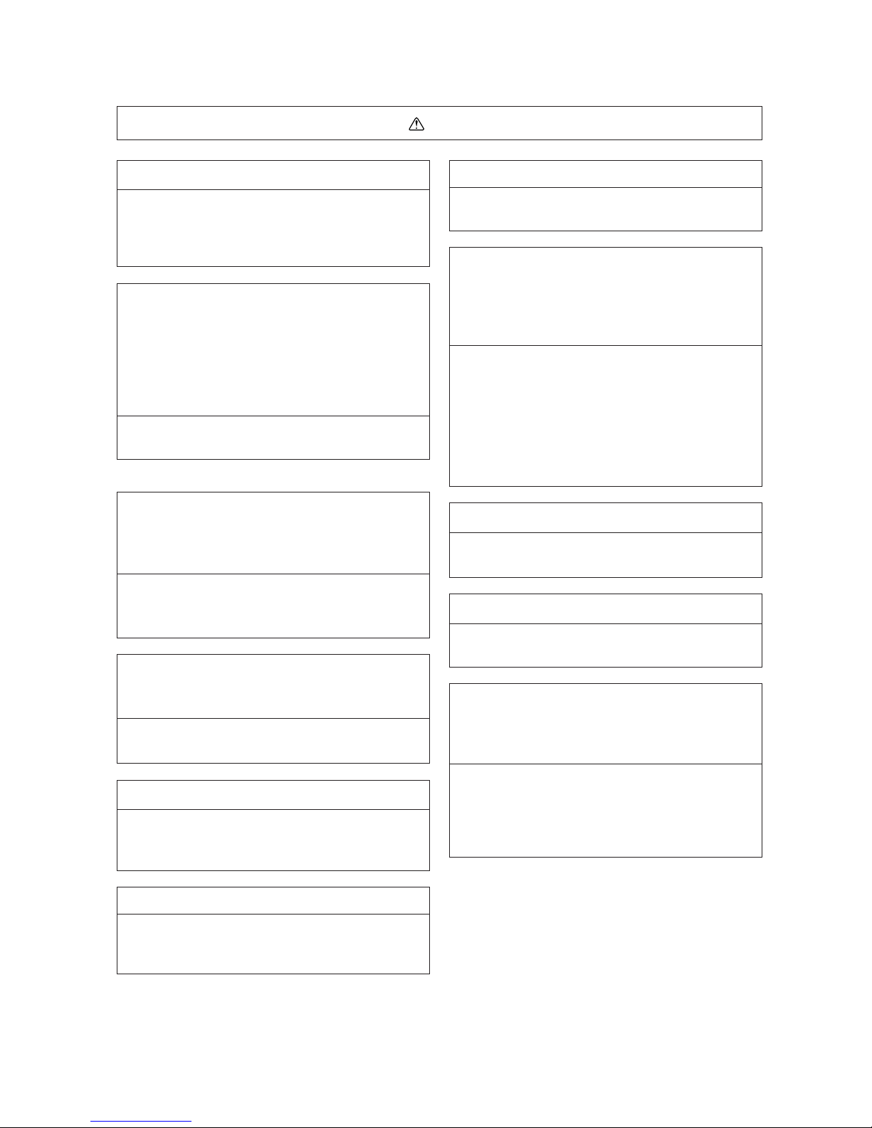
[1] Storage of Piping Material
(1) Storage location
Store the pipes to be used indoors. (Warehouse at site or owner’s warehouse)
Storing them outdoors may cause dirt, waste, or water to infiltrate.
(2) Pipe sealing before storage
Both ends of the pipes should be sealed until immediately before brazing.
Wrap elbows and T’s in plastic bags for storage.
* The new refrigerator oil is 10 times more hygroscopic than the conventional refrigerator oil (such as Suniso). Water
infiltration in the refrigerant circuit may deteriorate the oil or cause a compressor failure. Piping materials must be
stored with more care than with the conventional refrigerant pipes.
Page 6
–3–
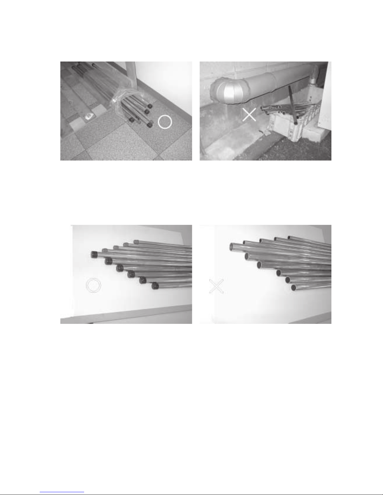
[2] Piping Machining
Use ester oil, ether oil or alkylbenzene (small amount) as the refrigerator oil to coat flares and flange connections.
Use only the necessary minimum quantity of oil !
Reason:
1. The refrigerator oil used for the equipment is highly hygroscopic and may introduce water inside.
Notes:
• Introducing a great quantity of mineral oil into the refrigerant circuit may also cause a compressor failure.
• Do not use oils other than ester oil, ether oil or alkylbenzene.
Page 7
–4–
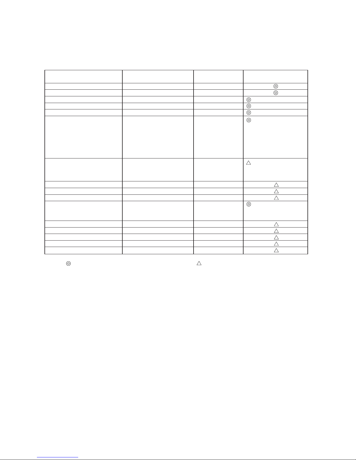
[3] Necessary Apparatus and Materials and Notes on Their Handling
The following tools should be marked as dedicated tools for R407C.
<<Comparison of apparatus and materials used for R407C and for R22>>
Apparatus Used Use R22 R407C
Gauge manifold Evacuating, refrigerant filling Current product
Charging hose Operation check Current product
Charging cylinder Refrigerant charging Current product Do not use.
Gas leakage detector Gas leakage check Current product Shared with R134a
Refrigerant collector Refrigerant collection R22 For R407C use only
Refrigerant cylinder Refrigerant filling R22
Vacuum pump Vacuum drying Current product
Vacuum pump with a check valve Current product
Flare tool Flaring of pipes Current product
Bender Bending of pipes Current product
Application oil Applied to flared parts Current product
Torque wrench Tightening of flare nuts Current product
Pipe cutter Cutting of pipes Current product
Welder and nitrogen cylinder Welding of pipes Current product
Refrigerant charging meter Refrigerant charging Current product
Vacuum gauge Checking the vacuum degree Current product
Symbols:
To be used for R407C only. Can also be used for conventional refrigerants.
Tools for R407C must be handled with more care than those for conventional refrigerants. They must not come into contact
with any water or dirt.
Identification of dedicated use for R407C
: Record refrigerant
name and put brown
belt on upper part of
cylinder.
Can be used by
attaching an adapter
with a check valve.
Ester oil or Ether oil or
Alkybenzene (Small
amount)
Page 8
–5–
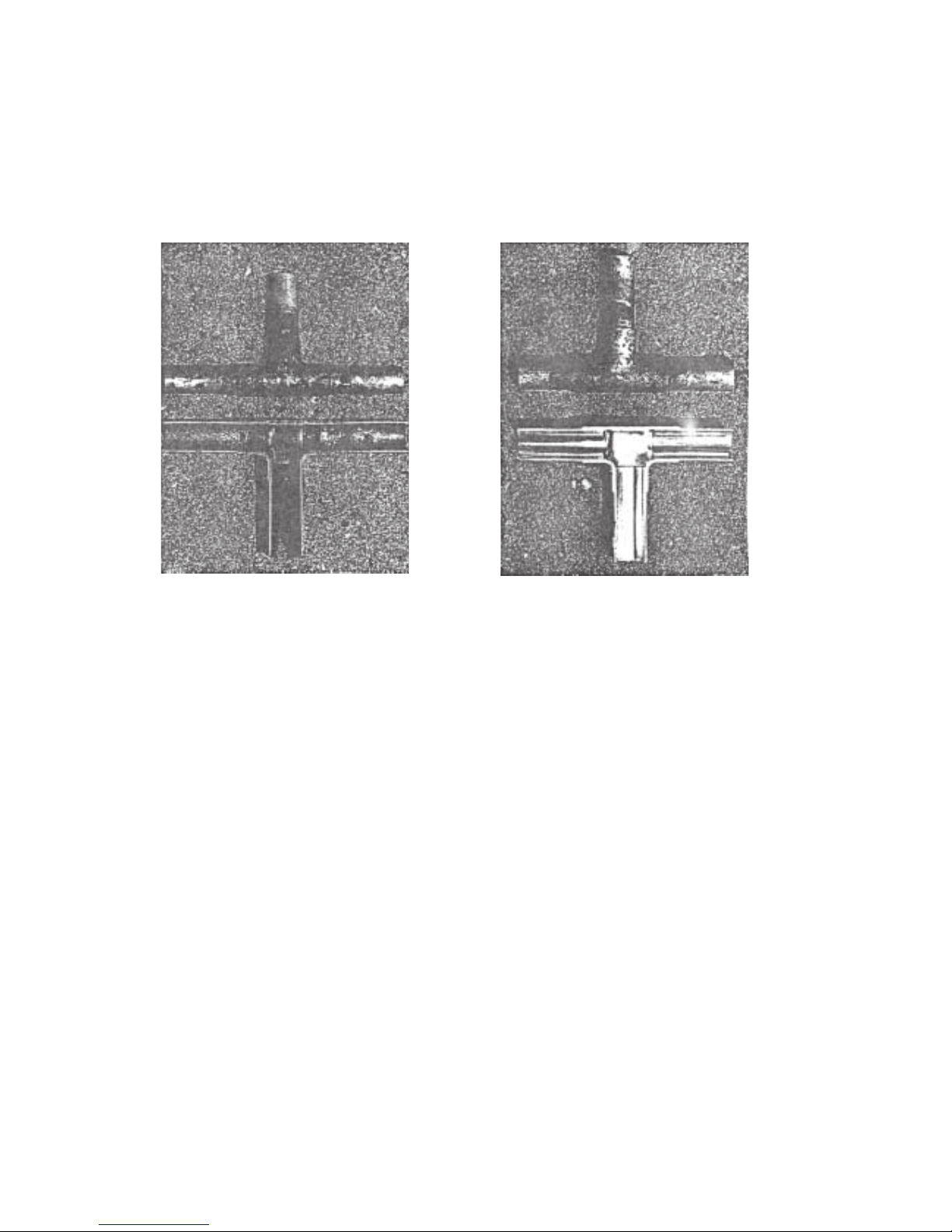
[4] Brazing
No changes from the conventional method, but special care is required so that foreign matter (ie. oxide scale, water, dirt,
etc.) does not enter the refrigerant circuit.
Example: Inner state of brazed section
When non-oxide brazing was not used When non-oxide brazing was used
Items to be strictly observed:
1. Do not conduct refrigerant piping work outdoors on a rainy day.
2. Apply non-oxide brazing.
3. Use a brazing material (Bcup-3) which requires no flux when brazing between copper pipes or between a copper pipe
and copper coupling.
4. If installed refrigerant pipes are not immediately connected to the equipment, then braze and seal both ends of them.
Reasons:
1. The new refrigerant oil is 10 times more hygroscopic than the conventional oil. The probability of a machine failure if
water infiltrates is higher than with conventional refrigerant oil.
2. A flux generally contains chlorine. A residual flux in the refrigerant circuit may generate sludge.
Note:
• Commercially available antioxidants may have adverse effects on the equipment due to its residue, etc. When
applying non-oxide brazing, use nitrogen.
Page 9
–6–
[5] Airtightness Test
No changes from the conventional method. Note that a refrigerant leakage detector for R22 cannot detect R407C
leakage.
Halide torch R22 leakage detector
Items to be strictly observed:
1. Pressurize the equipment with nitrogen up to the design pressure and then judge the equipment’s airtightness, taking
temperature variations into account.
2. When investigating leakage locations using a refrigerant, be sure to use R407C.
3. Ensure that R407C is in a liquid state when charging.
Reasons:
1. Use of oxygen as the pressurized gas may cause an explosion.
2. Charging with R407C gas will lead the composition of the remaining refrigerant in the cylinder to change and this
refrigerant can then not be used.
Note:
• A leakage detector for R407C is sold commercially and it should be purchased.
[6] Vacuuming
1. Vacuum pump with check valve
A vacuum pump with a check valve is required to prevent the vacuum pump oil from flowing back into the refrigerant
circuit when the vacuum pump power is turned off (power failure).
It is also possible to attach a check valve to the actual vacuum pump afterwards.
2. Standard degree of vacuum for the vacuum pump
Use a pump which reaches 0.5 Torr (500 MICRON) or below after 5 minutes of operation.
In addition, be sure to use a vacuum pump that has been properly maintained and oiled using the specified oil. If the
vacuum pump is not properly maintained, the degree of vacuum may be too low.
3. Required accuracy of the vacuum gauge
Use a vacuum gauge that can measure up to 5 Torr. Do not use a general gauge manifold since it cannot measure a
vacuum of 5 Torr.
4. Evacuating time
• Evacuate the equipment for 1 hour after – 755 mmHg (5 Torr) has been reached.
• After envacuating, leave the equipment for 1 hour and make sure the that vacuum is not lost.
5. Operating procedure when the vacuum pump is stopped
In order to prevent a backflow of the vacuum pump oil, open the relief valve on the vacuum pump side or loosen the
charge hose to drawn in air before stopping operation.
The same operating procedure should be used when using a vacuum pump with a check valve.
Page 10
–7–
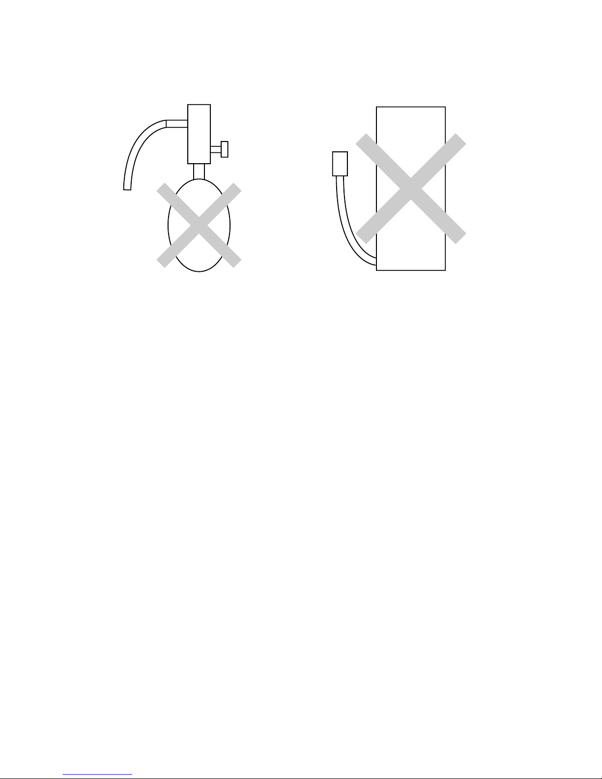
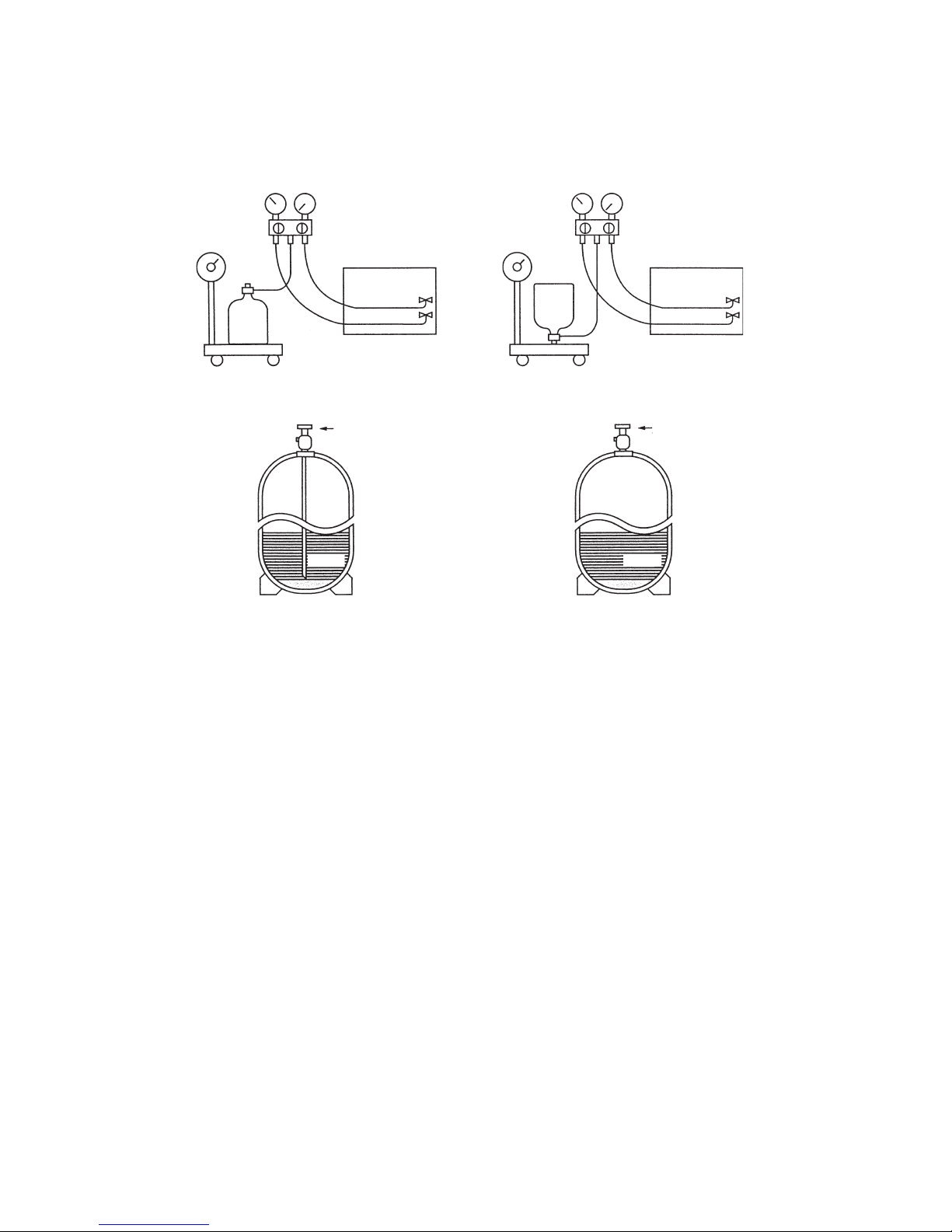
[7] Charging of Refrigerant
R407C must be in a liquid state when charging, because it is a non-azeotropic refrigerant.
For a cylinder with a syphon attached For a cylinder without a syphon attached
Cylinder color identification R407C-Gray Charged with liquid refrigerant
R410A-Pink
Reasons:
1. R407C is a mixture of 3 refrigerants, each with a different evaporation temperature. Therefore, if the equipment is
charged with R407C gas, then the refrigerant whose evaporation temperature is closest to the outside temperature is
charged first while the rest of refrigerants remain in the cylinder.
Note:
• In the case of a cylinder with a syphon, liquid R407C is charged without turning the cylinder up side down. Check the
type of cylinder before charging.
[8] Dryer
1. Replace the dryer when the refrigerant circuit is opened (Ex. Change the compressor, full gas leakage). Be sure to
replace the dryer with a CITY MULTI Series Y, Super Y (For use with R407C).
If any other product is used, the unit will be damaged.
2. Opening the refrigerant circuit after changing to a new dryer is less than 1 hour. The replacement of the dryer should
be the last operation performed.
Cylin-
der
Cylin-
der
Valve
Val ve
Liquid
Liquid
Page 11
–8–
22
22
2 COMPONENT OF EQUIPMENT
[1] Appearance of Components
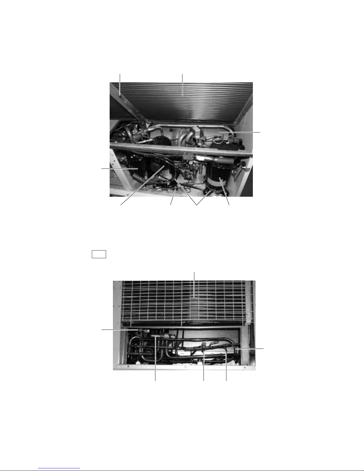
1 Variable capacity unit
Rear
Ambient temperature Sensor
Heat Exchanger
Accumulator
Heat Exchanger of CS circuit
(PUHY-P-YMF-B only)
Solenoid Valve
(SV5b)
Variable Capacity
Compressor (No.1
Compressor)
Four-way Valve
(21S4b)
Oil Separator
Four-way Valve
(21S4a)
Heat Exchanger
Sub-cool Ciol
Oil Equalization Pipe Belt Heater Constant Capacity Compressor
(No.2 Compressor)
Page 12
–9–
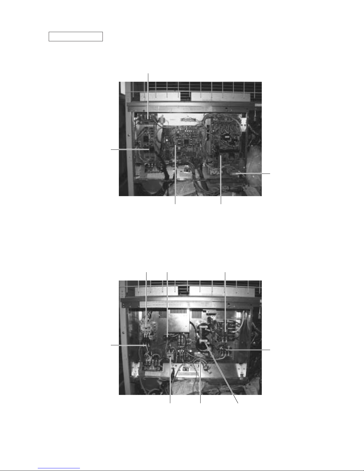
Controller Box
RELAY board
FANCON board
MAIN board INV board
Choke coil (L2)
Magnetic contactor
(52C2)
Magnetic contactor
(52F)
Transistor module
(TRM)
Thermal overload
(51C2)
Thyristor module
(SCRM)
Magnetic contactor
(52C1)
Capacitor (C2, C3)
(Smoothing capacitor)
Diode stack (DS)
Page 13
–10–
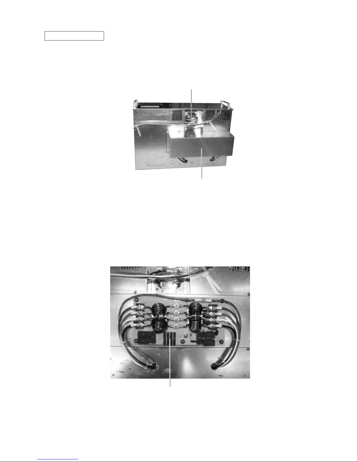
Noise filter (NF)
DC reactor (DCL)
Noise filter box
Noise Filter Box
(Rear of the controller box)
Page 14
–11–
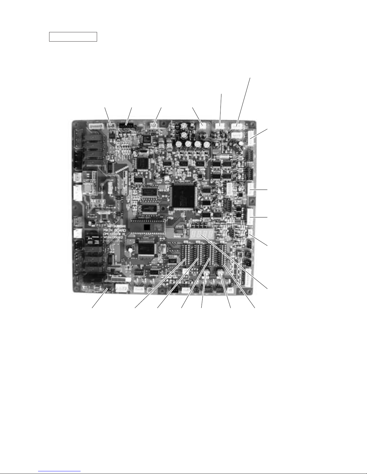
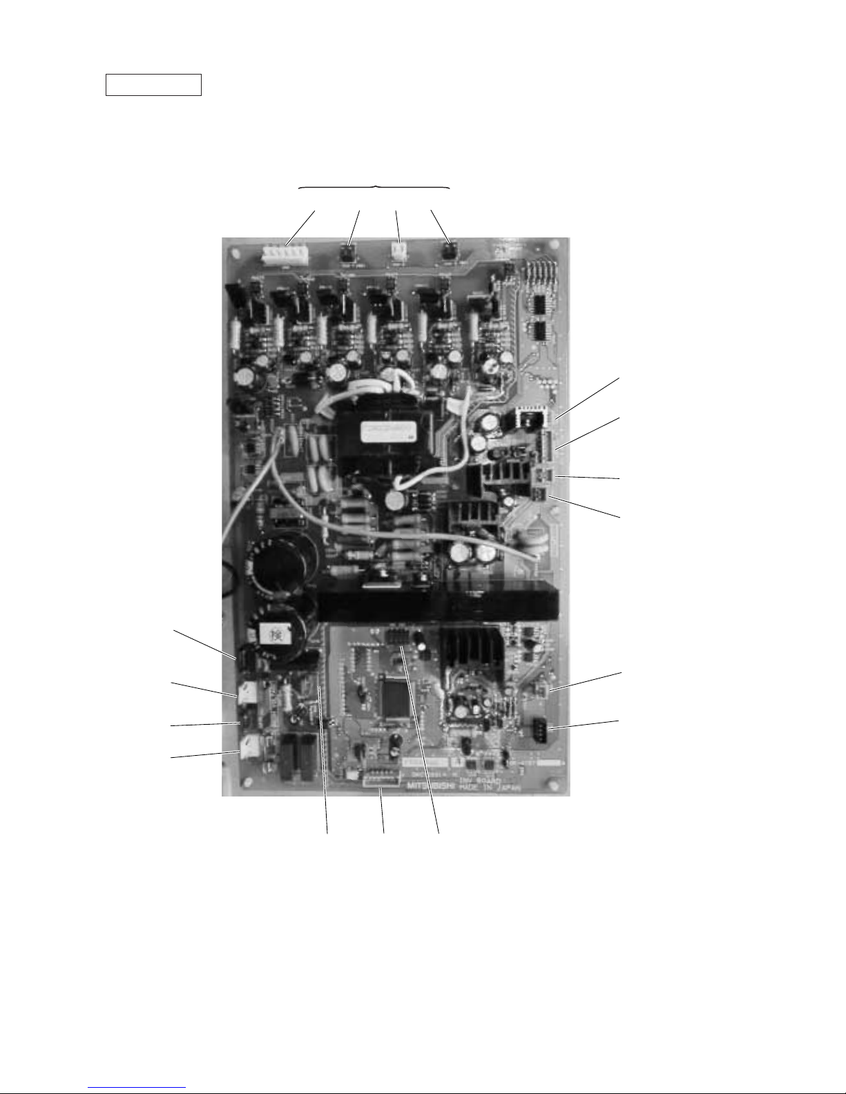
MAIN board
CNTR CNFC1
CNVCC4
Power source for
control
CNS1
M-NET
transmission
CNS2
M-NET
transmission
(Centralized
control)
CN40
M-NET transmission
power supply
CNVCC3
Power source for control
1-2 30 V, 1-3 30 V
4-6 12 V, 5-6 5 V
CN51
Indication distance
3-4 Compressor
ON/OFF
3-5 Trouble
CNRS3
Serial transmission to
INV board
CN3D
Cooling/Heating auto
changeover
CN20
Power supply
3 L1
1 N
SW4 SW3 SW2 SWU2 SWU1 SW1
LD1
Service LED
Page 15
–12–
INV board
CN3 CN2-1 CN2-2 CN2-3
CNVDC
CN52C
CNFAN
CNAC2
CNR CNRS2 SW1
CNCT
CN30V
CNTH
CNL2
CNVCC1
CNVCC2
Power source
1 L2
3 N
Power supply (5 V)
Power supply
1-2 30 V, 1-3 30 V,
4-6 12 V, 5-6 5 V
Output to transistor module
Page 16

–13–
FANCON board
CNV CNW
CNU CNFC2
Page 17
–14–
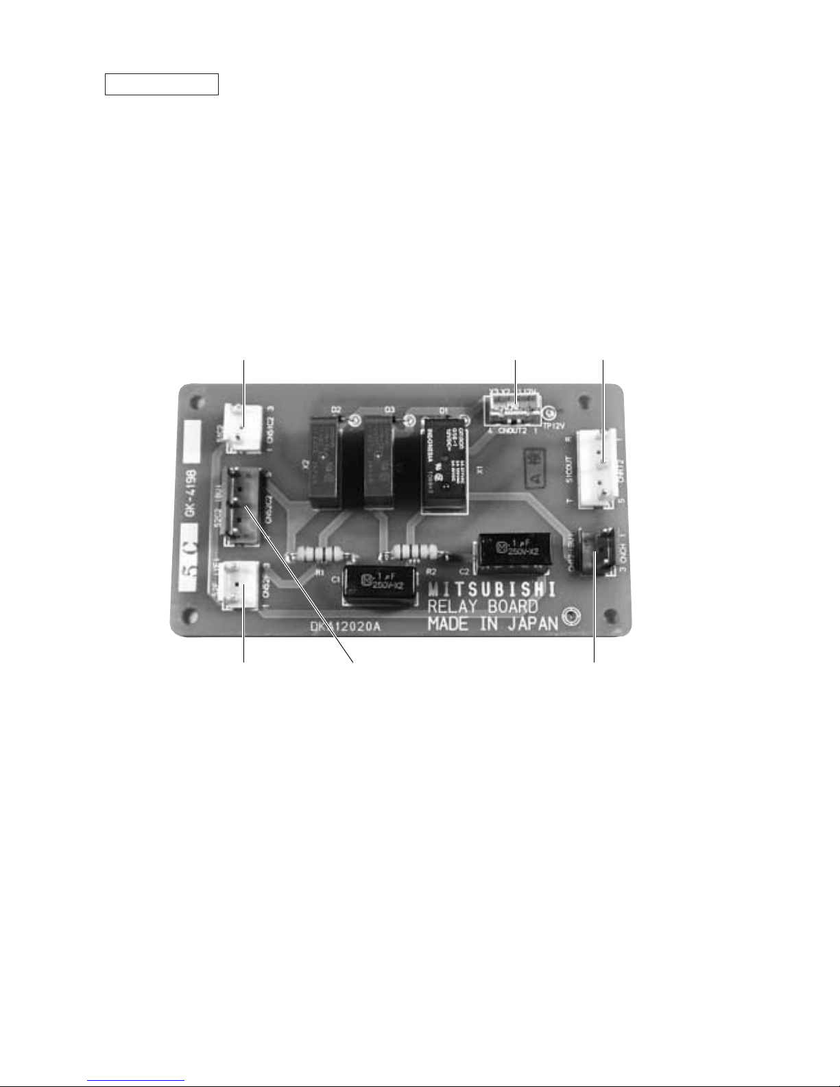
RELAY board
CN51C2 CNOUT2 CNRT2
CN52F CN52C2 CNCH
Page 18
–15–
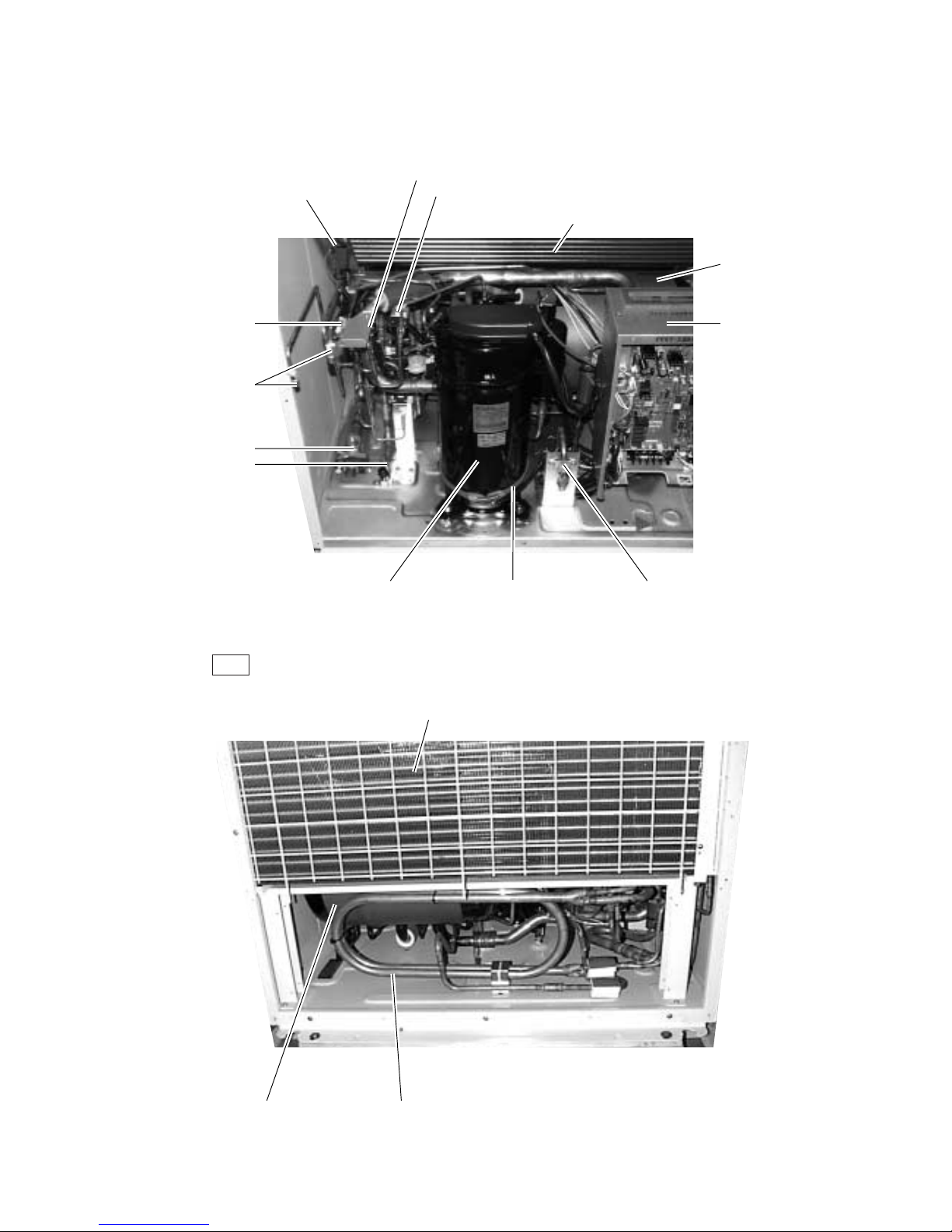
2 Constant capacity unit
Rear
Heat exchanger
Accumulator Sub-cool coil
Ambient temperature sensor
Solenoid valve (SV3, PUHN-P-YMF-B only)
Solenoid valve (SV2, PUHN-P-YMF-B only)
Accumlator
Controller box
Oil balance pipeBelt heater
Constant capacity compressor
(No.3 compressor)
Liquid ball valve
Gas ball valve
Service check-point
(right; high pressure,
left; low pressure)
Four- way valve
Heat exchanger
Page 19
–16–
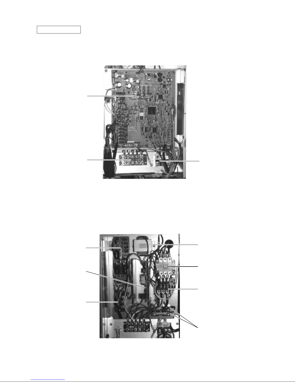
Controller Box
CONT board
Terminal block TB1
powersource
Terminal block TB3
transmission
FANCON board
Transformer
Noise Filter (NF)
Thyristor module
(SCRM)
Magnetic contactor
(52C)
Thermal overload relay
(51C)
Fuses (F1,F2)
Page 20

–17–
CONT board
SWU2
CNTR
SWU1
CNFC1
SW3
SW2
CNS1
M-NET
transmission
CN20
Power supply
1 N
3 L1
Page 21
–18–
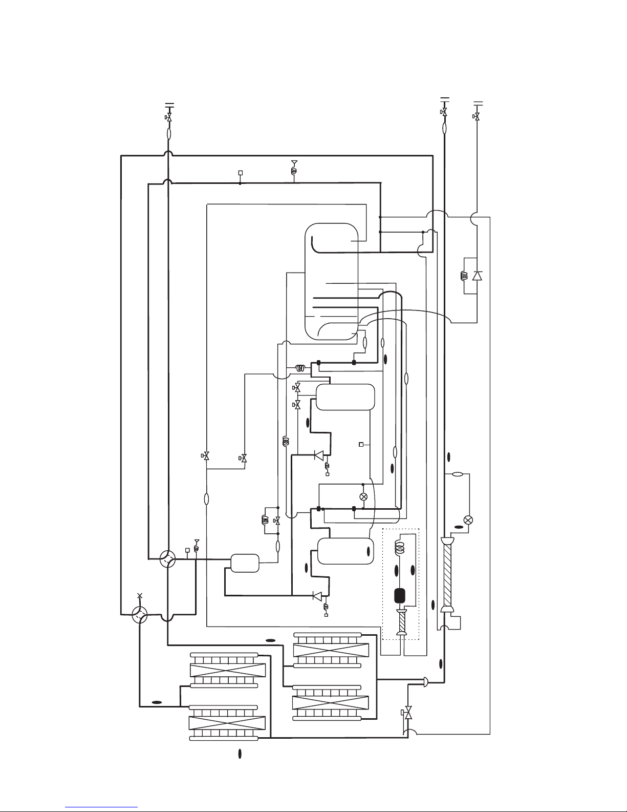
BV3
TH6
TH7
TH8
TH5
CJ1
O/S
63HS
TH11
HEX2b
HEX1b
CJ2
CV1
SV4
SV1
CP1
TH4
TH3
CP4
BV2
BV1
TH12
Comp2
Comp1
HEX2a
HEX1a
CV2
SA
MA
CP3a
SV6
SCC
LEV1
63H1
63H2
21S4a
21S4b
SV5b
SV22
SV32
ST5
ST6
CP3b
ST3
ST4
ST9
ST8
TH9a
ST2
ST1
CJ3
ST7
TH9b
TH2
Drier
CP2
CS-circuit
TH10c
63LS
CV3
CP5
TH10a
TH10b
SLEV
[2] Refrigerant Circuit Diagram and Thermal Sensor
1 PUHY-P400·500YMF-B
Page 22
–19–
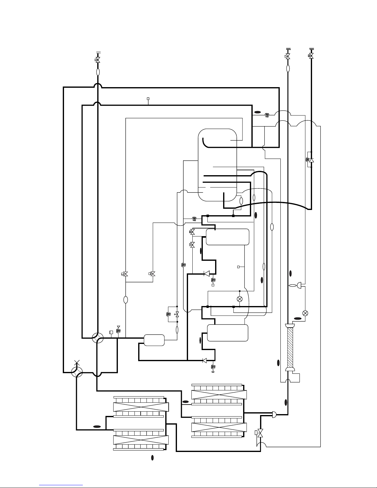
2 PUHY-400·500YMF-B
CP1
ST6
SV1
SLEV
CP4
No.1
Comp.
TH8
HEX2a
TH5
SV5b
HEX1a
TH6
HEX2b
HEX1b
21S4b
21S4a
CJ1
63HS
ST5
SV4
SV6
TH11
63H1
CV1
O/S
CJ2
BV1
ST1
MASA
TH2
CP2
ST2
BV2
BV3
ST8
ST9
TH3
ST3
TH7
ST7
TH9
TH10b
TH10a
LEV1
SCC
TH4
ST4
CJ3
63H2
CV2
CP3a
SV22
SV32
TH12
CP3b
No.2
Comp.
CV3
CP5
* There are SV22, SV32 only for PUHY-500YMF-B
Page 23
–20–
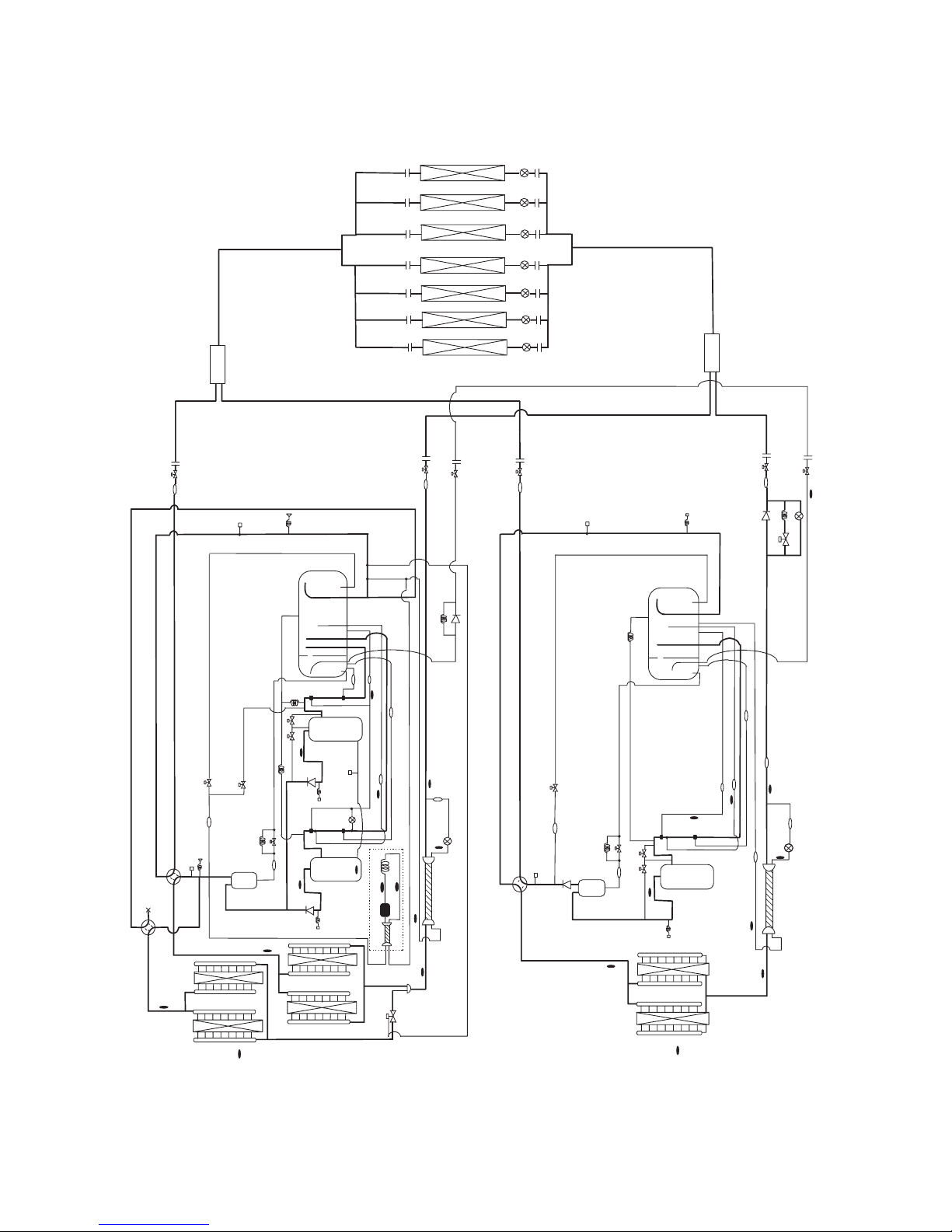
3 PUHY-P600·650·700·750YSMF-B
Distributer(Gas)
Indoor unit
Oil balance
pipe
BV3
TH6
TH7
TH8
TH5
CJ1
O/S
63HS
TH11
HEX2b
HEX1b
CJ2
CV1
SV4
SV1
CP1
TH4
TH3
CP4
BV2
BV1
TH12
Comp2
Comp1
HEX2a
HEX1a
CV2
SA
MA
CP3a
SV6
SCC
LEV1
63H1
63H2
21S4a
21S4b
SV5b
SV22
SV32
ST5
ST6
CP3b
ST3
ST4
ST9
ST8
TH9a
ST2
ST1
CJ3
TH9b
TH2
Drier
CP2
CS-circuit
TH10c
63LS
CV3
CP5
TH10a
TH10b
Distributer(Liquid)
SCC
TH7
TH5
O/S
TH11
CJ2
SV4
SV1
CP1
CP4
TH4
TH3
BV2
BV1
Comp1
HEX2
HEX1
SV5b
SA
MA
CP3
LEV1
63H
21S4
CJ1
CV1
BV3
ST1
ST2
ST5
ST6
ST9
ST3
ST4
ST8
TH10a
CV2
CP5
LEV2
TH6
63LS
ST10
ST7
TH9
TH8
TH10b
SV3
SV2
SLEV
PUHY-P400,500YMF-B
PUHN-P200,250YMF-B
Page 24
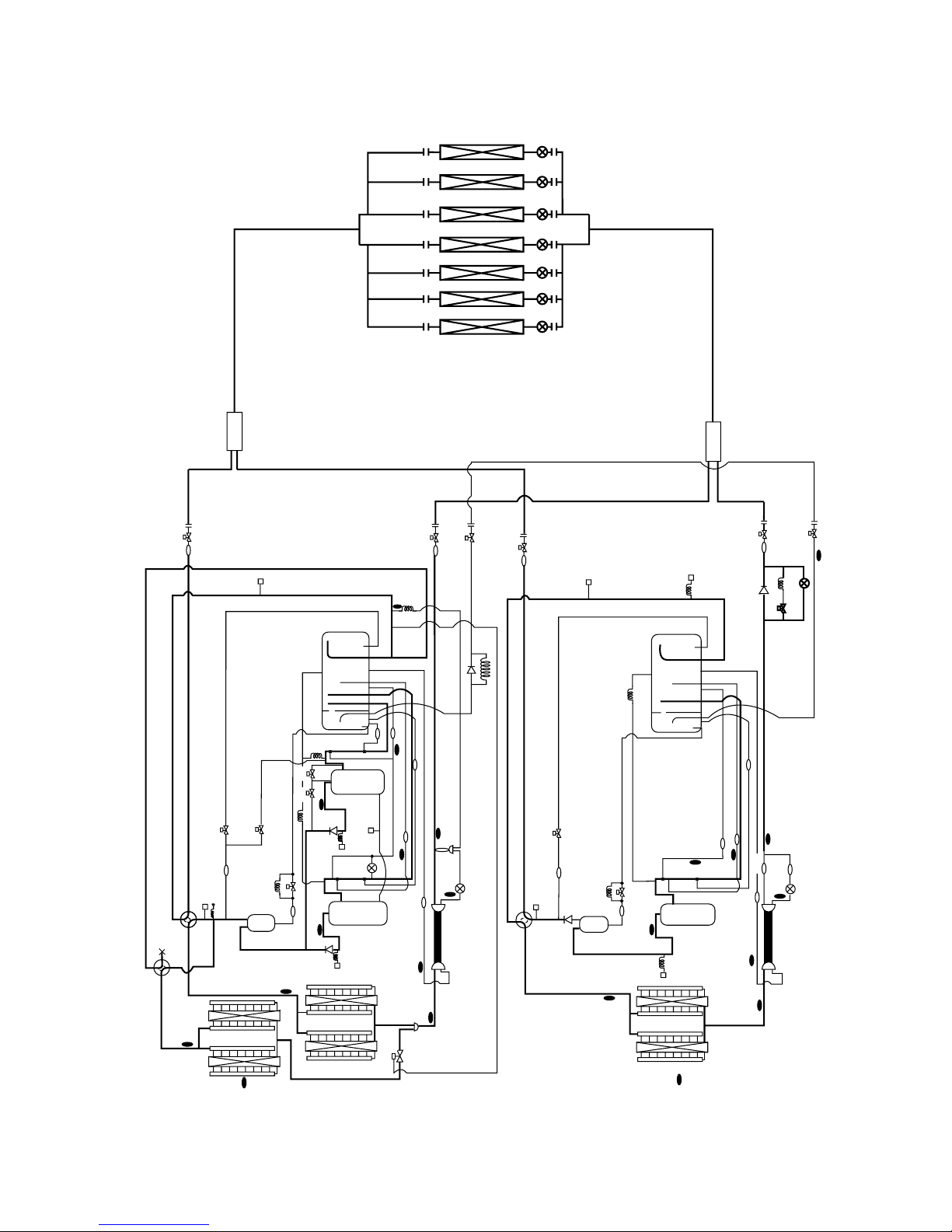
–21–
21S4b
HEX1b
TH6
TH10b
HEX2b
21S4a
CJ1
63HS
ST5
SV4
SV6
TH10a
O/S
ST6
CP1
SV1
HEX1a
HEX2a
SV5b
TH5
CV1
63H1
TH11
Comp1
Comp2
TH8
ST10
CP4
SLEV
TH4
ST4
ST8
CJ3
63H2
CV2
CP3a
TH12
SV22 SV32
CP3b
ST9
SA
MA
TH3
ST3
TH9
LEV1
ST7
TH7
TH2
CP2
CP5
CV3
CJ2
SCC
SCC
ST1
BV1
Distributer (Gas)
Indoor unit
BV2
ST2
BV3
BV1
ST1
CJ2
63LS
MA
SA
CP3
ST8
ST4
TH4
ST3
TH3
CP4
CP1
SV1
ST6
CV1
O/S
CJ1
ST5
SV4
21S4
TH11
63H
Comp1
TH10a
TH6
HEX1
HEX2
TH5
TH8
ST10
TH9
LEV1
ST7
TH7
CV2
BV2
SV5b
CP5
LEV2
ST2
TH10b
BV3
Oil balance pipe
Distributer (Liquid)
ST9
4 PUHY-600·650·700·750YSMF-B
PUHY-400,500YMF-B
PUHY-200,250YMF-B
Page 25
–22–
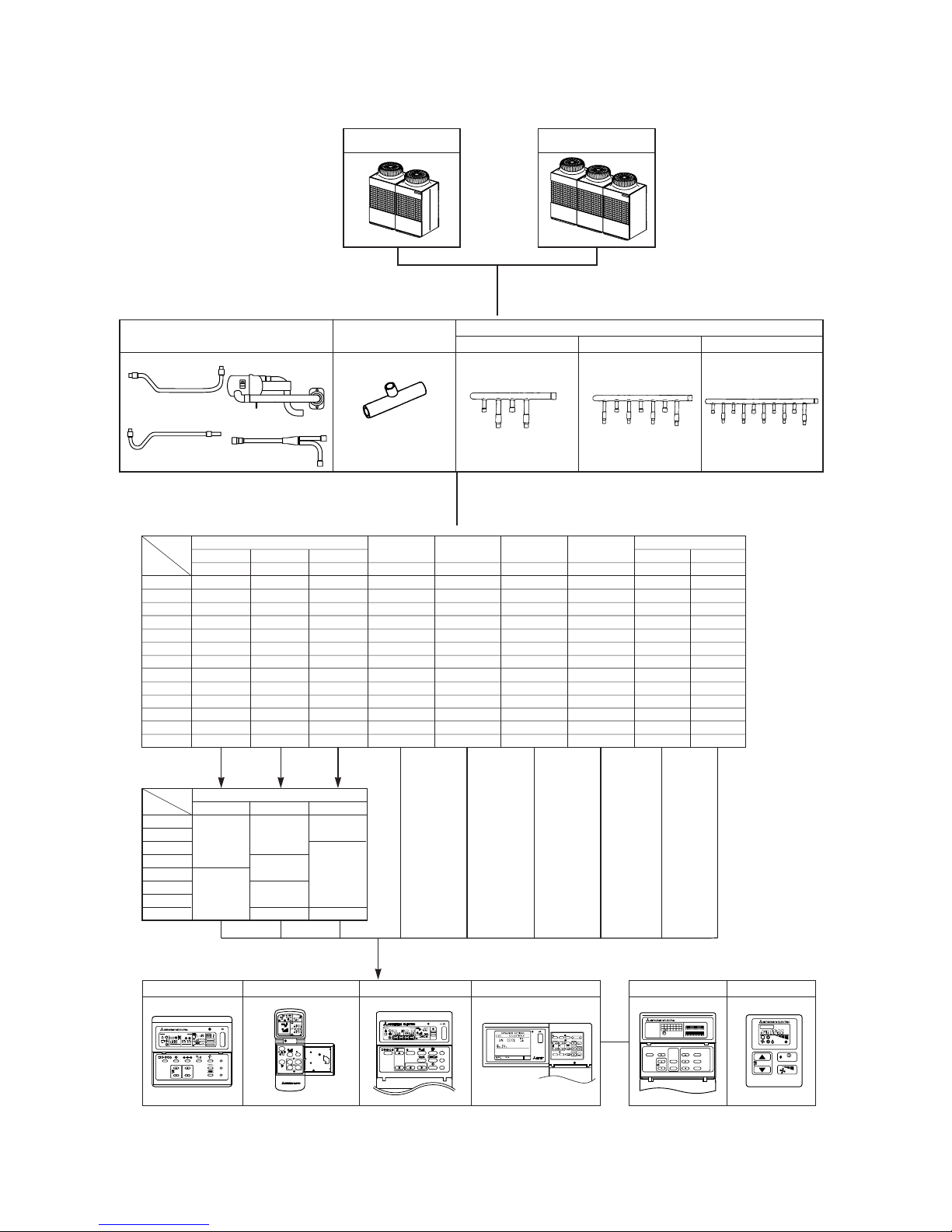
40LW-F
D. Indoor unit
Cassette ceiling
Ceiling
concealed
Wall mounted
Ceiling
suspended
Floor standing
Exposed Concealed
PLFY-PPLFY-P PEFY-P PKFY-P PCFY-P PFFY-P PFFY-P
4-way flow2-way flow
20 -20VLMD 20VML 20VAM - 20VLEM 20VLRM
25 -25VLMD 25VML 25VAM - 25VLEM 25VLRM
32 32VKM32VLMD 32VML 32VGM - 32VLEM 32VLRM
40 40VKM40VLMD 40VMH 40VGM 40VGM 40VLEM 40VLRM
50 50VKM50VLMD 50VMH 50VGM - 50VLEM 50VLRM
63 63VKM63VLMD 63VMH - 63VGM 63VLEM 63VLRM
140 -- 140VMH - - - -
80
100
125
80VKM
100VKM
125VKM
80VLMD
100VLMD
125VLMD
80VMH
100VMH
125VMH
-
-
-
100VGM
125VGM
-
-
-
-
-
-
E. Option (panel)
Decoration panel
PMP- CMP20
25
32
40
50
63
80
100, 125
-
-
3GB
32LW-F
40MB
63LW-F
125LW-F
PLP-
6GB
Model
Capacity
Model
Capacity
F. Remote controller
Ceiling mounted
built-in
71
-
PMFY-P
1-way flow
20VMB
25VBM
32VBM
40VBM
-
-
-
-
-
-
-
-
71VMH
PDFY-P
20VM
25VM
32VM
40VM
50VM
63VM
-
80VM
100VM
125VM
250 -- 250VMH - - - -
200 -- 200VMH -
-
--
-
-
-
-
71VM
-
-
--
PAR-F25MA MJ-103MTRAPAC-FL31MA PAC-SC30GRA PAC-SC32PTA PAC-SE51CRA
6
GROUP
SELECT
MODE
TEST RUN
AIR
DIRECTION
FAN SPEED
ON/OFF
0
87
54
CLOCK/
PATTERN
PROHIBITION
TIMER
MODE
TEMP.
REMOTE
MJ-103MTRA
CENTRAL CONTROLLER
9
SCREEN
BACK
ENTER
VENTILATION
RESET
ON/OFF
123
INS.
DEL.
ON/OFF
–
STAND BY
DEFROST
ERROR CODE
OA UNIT ADDRESS NO.
CENTRALLY CONTROLLED
CLOCK
ON OFF
˚C
1Hr.
NOT AVAILABLE
˚C
CHECK MODE
FILTER
CHECK
TEST RUN
ON OFFCLOCK
FILTER
CHECK
TEST RUN
REMOTE CONTROLLER
NETWORK
PAR-F25MA
TEMP. TIMER SET
INDOOR UNIT
ADDRESS NO.
SMTWTFS
SET
SET BACK
036912
12 15 18 21 24
SET/MONITOR TODAY
WEEKLY
SETTING
PROGRAM TIMER
PAC-SC32PTA
DAILY
SETTING
ON
SET BACK ON
CLOCK
OFF
DAILY TIMER
OFF
SET BACK
CENTRAL
TEMP.CHECK
˚C
TEMP.
ON/OFF
PAC-SE51CRA
˚C
˚C
ON/OFF
ON/OFFTEMP.
GROUP
FILTER
CHECK
TEST RUN
GROUP
REMOTE CONTROLLER
PAC-SC30GRA
TEST RUN
FILTER
CHECK MODE
OFF
ADDRESS
ON
NOT AVAILABLE
COLLECTIVE
GROUP
CHECK
CENTRALLY CONTROLLED
˚C
AM
PM
PM
CLOCK
AM
CHECK
MODE
NOT AVAILABLE
TEST RUN
ON/OFF
HR.
STOP
START
MIN.
VANE
FAN
[3] Equipment Composition
A. Outdoor Unit
B. Branch Pipe Kit
In the case of the PUHY-(P)YSMF-B, the CMC-30A is
necessary.
Branch joint
Branch header
4-connection 7-connection 10-connection
▼
▼
CMY-Y104-E CMY-Y107-E CMY-Y1010-E
CMC-30A*
Oil balance pipe 1 Distributer (gas)
Oil balance pipe 2 Distributer (liquid)
CMY-Y102S-F CMY-Y102L-F
CMY-Y202-F CMY-Y302-F
PUHY-(P)600·650·700·750
YSMF-B
PUHY-(P)400·500YMF-B
Page 26

–23–
Page 27
–24–
*3:NF is in the back of the Inverter Controller Box.
(Refer to the <Unit Internal layout>.)
6
4
2
5
3
1
6
4
2
5
3
1
Black
White
Red
Black
White
Red
CH11
Fan motor
(Heat exchanger)
Fan motor
(Heat exchanger)
Black
White
Red
51C2/Model P400,(P)500: 27A
Model 400 : 17.5A
Refer to the Service handbook about the switch operation.
SW4-6
OFF
ON
as connection with
PUHN-(P)200/250YMF-B
A
A
BOX BODY
BOX BODY
*2
*1
*2
circuit
detection
There are not “*1” on “PUHY-400YMF-B
”.
There are not “*2” on “PUHY-400/500YMF-B
”.
Black
White
Red
TH10a
TH10b
4321
(4P)
CN13
SV5b
SV6
21S4b
SV4
SV32
DEMAND
SNOW
NIGHT
1-2
CN3S
1-3
CN3N
1-2
Mode
132
CN3N
(3P)
circuit
detection
CN05
12345
6
N
L3
L2
L1
N
L3
L2
L1
Yel l o w
Green/
Blue
Black
White
Red
NF
Yel l o w
Green/
Blue
Black
Red
White
L1
TB1A
BOX BODY
N
L3
L2
3
CNMF2
52C2
14
13
A2
A1
A2
A1
52C2
123
4
5
1
2
3
1
2
3
1
2
123
4
12345
96
95
51C2
CH12
TH12
12 12 1234
CN07
(2P)
CN06
(2P)
CN35
(3P)
CN34
(6P)
654321321
1
2
3
CN38
(3P)
X10
43
21
SSR
X04
X05
21S4a
SV22
CH2
CH3
63H1
TH6
TH3TH4
CN05
(4P)
X07
X06
12345
6
(6P)
CN36
X09
X08
12345
6
(6P)
CN37
(2P)
21
63H2
1
234
5
X02
X03
X01
RELAY board
CNRT1
(5P)
(5P)
CNRT2
(3P)
CNCH
(3P)
CN51C2
CN52C2
(5P)
CN52F
(3P)
TH9a
(2P)
21
(4P)
CNOUT2
(6P)
CNOUT1
CN09CN12
TH9b TH10c
52F
Black
White
Red
Motor (Compressor)
Control circuit board
52F
U
W
MF2
V
U
W
MC2
V
1
3
5
6
4
2
6
5
4
3
2
1
52C2
51C2
COOL
HEAT
Normal
changeover
Auto
Mode
CN3D
OFF
ON
1-3
OFF
ON
OFF
ON
1-2
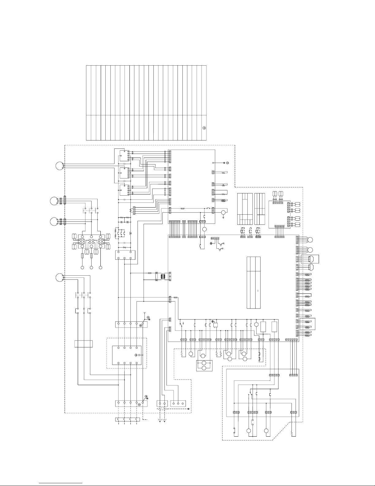
<WIRING DIAGRAM>
Earth terminal
Thermistor
Terminal block
(5P)
CNU
(6P)
CNFC2
(5P)
CNV
(5P)
CNW
Noise Filter
NF
Power transistor module
TRM1~3
Ferrite core
FB1
Diode stack
DS
Electronic expansion valve
Crank case heater(Compressor)
CH11,12
Solid state relay
SSR
Magnetic contactor (Inverter main circuit)
Name
Symbol
High pressure switch
21S4a,b
4-way valve
LEV1,SLEV
Solenoid valve
CH2,CH3
Cord heater
High pressure switch63HS,63LS
63H1,2
ZNR4
Current Sensor
52C1
Magnetic contactor
52C2
Magnetic contactor
52F
Overload Relay
51C2
DCCT
DC reactor
(Power factor improvement)
L2
SV1,22,32,4,5b,6
Choke coil(Transmission)
<SYMBOL EXPLANATION>
Fan (Radiator panel)
TB1, 1A, 3,7
DCL
MF1
Blue
Red
Orange
Brown
Red
White
Yellow
Black
Purple
Black
Brown
Red
Inverter Controller Box
BOX BODY
(INV board)
Power circuit board
L2
Orange
Yellow
Black
R7
Purple
MF1
(2P)
CN30V
(2P)
CNL2
(6P)
CN3
(5P)
CNLV2
(3P)
CNTR
(5P)
CNLV1
(3P)
CN32
(3P)
CNL
(2P)
CN2-1
(3P)
CNH
(2P)
CN01
THHS
(8P)
CN02
(2P)
CN2-2
(3P)
CN03
(3P)
CNFAN
(7P)
CNRS3
(6P)
CNVCC1
(4P)
CNCT
(6P)
CNVCC3
(2P)
CNVCC2
(7P)
CNRS2
X10
X01
X02
52C1
32165
1234567121432
2
6
3
54
1
32
2
11
1
21
2
21
31
243
2
21
1
43
2
21
FG
12
3
BlackRed
Motor (Compressor)
Varistor
V
MC1
W
C20
C23 C24
C21 C22
U
C25
White
12
DCCT
34
C16
C15
C14
B1
E1
E2
E2
B2
C2E1
TRM3
C1
C2E1
B2
E2
E2
E1
B1
B1
E1
E2
E2
B2
C2E1
C1
TRM2
CNTR1
1A F
250VAC
F3
T01
R3
R2
C3
C2
DCL
+
TRM1
+
52C1
R1
R5
C1
ZNR4
+
~
-~
C1
DS
~
TB7
M2
M1
TB3
controller
remote
Indoor and
Connect to
Yellow
Green/
Blue
Black
Red
White
PE
SLEV
L1
63LS
Red
White
Black
321
63HS
Red
White
Black
TH5 TH8
TH7
TH2
TH11
321
2A F
250VAC
F1
L2
TB1
LEV1
SV1
(MAIN board)
50/60 Hz
380/400/415 V
3N~
Power source
L3
N
4:Compressor ON/OFF
5:Trouble
N
12V
X01
X02
(2P)
CNTH
(4P)
CNVDC
3
(3P)
CN52C
2
(3P)
CNR
(3P)
CNX10
1
(3P)
CNS2
2
(3P)
CNAC2
(5P)
CN51
(2P)
CNS1
31
(2P)
CNVCC4
2
(2P)
CN2-3
1
1
2
3
2
(6P)
CNFC1
2
(3P)
CN20
3
(3P)
CN3S
(3P)
CN3D
1
1
(3P)
CN33
3
2A F
250VAC
F01
65432
1
5322413
625
5
1
43
1
2
213
5
3
4
4325
1
2
3
6217
3
1
2
1122
1
3
8
1
763211
4
2
1
3
3
4
VK1
VG1
VK2
VG2
WK1
WG1
WK2
TH2~12, THHS
(FANCON board)
Fan control board
WG2
123
54321 12345
6
5
UK2
UK1
UG1
5
4
UG2
V
CN04
Black
12A F
600VAC
321
4
MF3
L3
12A F
600VAC
F1
L2
W
L3
White
L1
F2
L2
Red
L1
U
V
VG2
VK2
VG1
VK1
WG1
W
WK2
WK1
UK2
U
UG1
SCRM
UG2
UK1
WG2
CNMF3
K
G
K
G
K
G
K
G
K
G
K
G
2
5
R6
PE
L3
1
L1
M1
M2
S
L2
6
4
2
5
3
1
FB1
<CAUTION>
·When checking for the inside control box,Be sure to turn the
power source off,And confirm that the voltage at the both
ends of main capacitor(C2,C3) is being sufficientry low by
opening MAIN board mounting plate after leaving 10minutes
or more.
·Please read the INSTALLATION MANUAL carefully.
[4] Electrical Wiring Diagram
1 PUHY-(P)400·500YMF-B
Page 28
–25–
FLAG3
FLAG2
FLAG1
FLAG5
FLAG6
FLAG7
<LED display>
FLAG4
FLAG8
LED1
TH7
❇3
PUHY-P400YMF-B
-(P)500YMF-B
PUHY-400YMF-B
SV22
MC2
63H2
TH12
SV5b
21S4b
SV6
SV4
SV1
TH12
63H2
MC2
<Internal layout>
63HS
63H1
63LS
TH3
TH4
TH5
TH6
TH10b
TH9b
SV32
LEV1
TH2
TH9a
TH8
TH11
MC1
Oil separator
21S4a
ACCUMULATOR
Inverter
Controller
Box
SLEV
*2
*2
*3
*2
NF
TH10a
TH10c
1102
❇ Please refer to the service handbook about other switch settings of LED display.
51
456327
910
21S4bSV4
SV22/32
109
OFF:0
ON:1
During
compres-
sor run
( at factory shipment)
FLAG7FLAG1
Display at LED lighting (blinking)
52C2 21S4a
FLAG6
Display
SW1 operation
Always
lighting
<Operation of self-diagnosis switch (SW1)and LED display>
81234567
FLAG3 FLAG4FLAG2
SV11
FLAG5
Relay output
display
(Lighting)
Check display1
(Blinking)
FLAG8
ON:1
FLAG8 always
lights at
microcomputer
power ON
18
OFF:0
52C1
❇
SV5b SV6 CH2,3 52F
SV5B is closed
when FLAG3 is
turned ON.
Display the address and error code by turns.
❇Only for PUHY-P400,
(P)500YMF-B
Remarks
Page 29
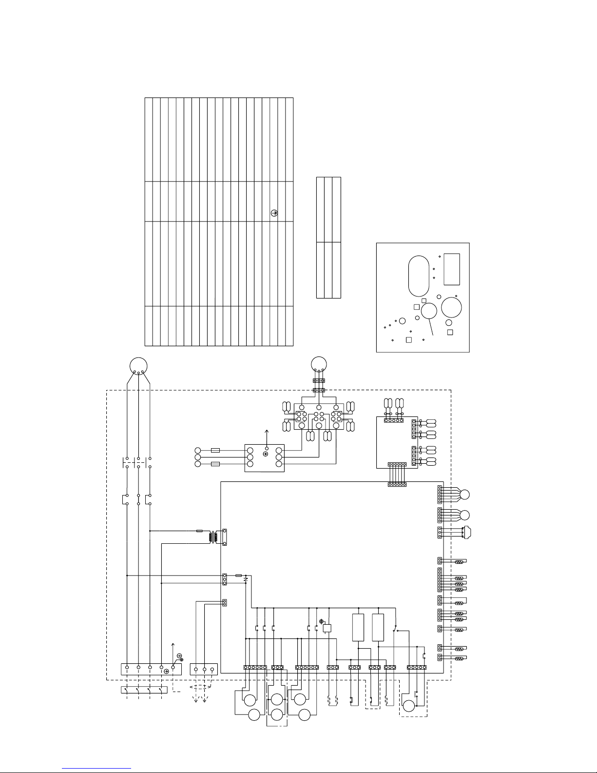
–26–
2 PUHN-(P)200·250YMF-B
Model 200: 24A
Model 250: 27A
*1
<Difference of appliance>
*1
Appliance
PUHN-P200·250YMF-B
PUHN- 200·250YMF-B
L2
L1
L3
PE
5
G
K
G
K
G
K
G
K
G
K
G
K
CNMF
WG2
UK1
UG2
SCRM
UG1
U
UK2
WK1
WK2
W
WG1
VK1
VG1
VK2
VG2
V
U
L1
Red
L2
F2
L1
L3
W
L2
F1
600VAC
8A F
L3
MF
4
1
2
3
600VAC
8A F
Black
CN04
V
Red
UG2
4
White
Black
5
UG1
UK1
UK2
5
6
5432112345
3
2
1
WG2
Fan control board
(Fancon board)
WK2
WG1
WK1
VG2
VK2
VG1
VK1
and ON for Model 250.
SW3-10 are OFF for Model 200.
12
1421 323 241 123 678 12 1 2 3 12345 12
1
345
2
3
4
5
6
CN09
(2P)
CN06
(2P)
1
1
3
CN20
(3P)
2
CNFC1
(6P)
2
3
2
1
CNS1
(2P)
1
2
3
12
CN38
(3P)
X01
N
N
L3
Power source
3N~
380/400/415V
50Hz
Control circuit board
(CONT board)
LEV2
L2
F1
250VAC
6.3A F
63H
TH11TH7TH8TH5
TH6
TH3TH4TH9
123
Black
White
Red
63LS
L1
LEV1
PE
TB1
White
Red
Black
Blue
Green/
Yellow
Invreter
unit
Unit body
TB3
M1
M2
T01
F3
250VAC
1A F
White
U
W
MC1
V
Motor (Compressor)
Red
Black
CN05
(4P)
CN03
(3P)
CN02
(8P)
CN01
(2P)
CNL
(3P)
CN33
(6P)
CNLV1
(5P)
CNTR
(2P)
CNLV2
(6P)
Controller Box
CNW
(5P)
CNV
(5P)
CNFC2
(6P)
CNU
(5P)
1
3
5
6
4
2
6
5
4
3
2
1
CN12
TH10b
12
(2P)
TH10a
1
2
3
3
2
1
5
4
3
2
1
6
6
5
4
S
X02
SV1
51C
CN46
(3P)
CNCH11
(3P)
CH11
52C1
CN52C1
(5P)
X06
X07
52C151C1
13
14
A1
A2
Detection
circuit
Detection
circuit
ZNR01
A
A
Fan motor
L1L2L3
L1L2L3
CH3
CH2
X05
X04
SSR01
12
34
3
2
1
1
2
3
4
5
6
(6P)
CN34
(3P)
CN35
3
CN39
(3P)
2
1
X03
SV3
SV2
SV4
SV
5b
21
S4
52
C1
NF
Noise
Filter
THERMISTER
SV2,SV3
SORENOID VALVE
21S4
MF
MC1
52C1
SSR
CH11
CH2,CH3
ZNR01
SV5b
63H
63LS
SV1,SV4
TH11
TH3
TH4
TH5
TH6
TH7
TH8
TH10a
TH10b
TH9
X01~X07
SW2,SW3
SWU1,2
TB1
LEV1
LEV2
THERMISTER
F3
THERMISTER
THERMISTER
THERMISTER
ELECTRONIC EXPANSION VALVE
RELAY
SWITCH
SWITCH
POWER SOURCE TERMINAL BLOCK
EARTH TERMINAL
THERMISTER
THERMISTER
THERMISTER
LOW SIDE PRESSURE SENSOR
HIGH PRESSURE CUT OUT SWITCH
SORENOID VALVE
4-WAY VALVE
CORD HEATER
CRANK CASE HEATER(COMPRESSOR)
FAN MOTOR(HEAT EXCHANGER)
ELECTRIC MOTOR OF COMPRESSOR
OVER CURRENT RELAY
MAGNET CNTACTOR
FUSE(1A)
SOLID STATE RELAY
VARISTOR
THERMISTER
ELECTRONIC EXPANSION VALVE
THERMISTER
NAMESYMBOL
F1,F2
FUSE(8A)
F1
FUSE(6.3A)
SYMBOL NAME
SORENOID VALVE
51C1
“*1” are not existed
ALL exists
Difference
There is not diagnostic switch in constant
capacity unit, but variable capacity unit can
diagnose it.
<Internal layout>
TH10a
TH8
TH5
TH7
63LS
SV1
63H
TH3
TH4
TH10b
TH11
SV5b
Oil
separater
TH6
TH9
SV4
LEV1
LEV2
21S4
MC1
ACCUMULATOR
Inverter
contoroller
box
(FRONT)
Page 30
–27–
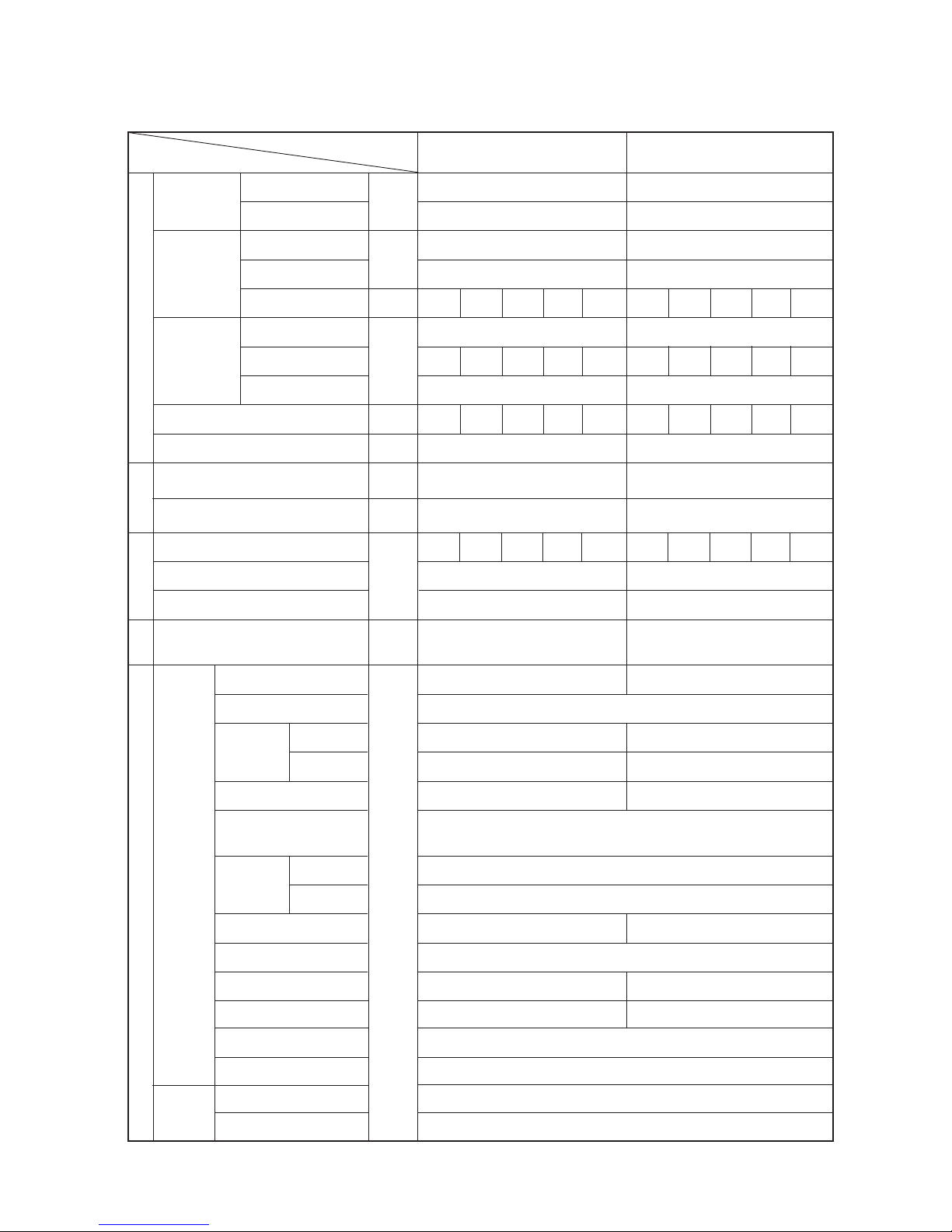
Discharge (TH11/TH12)
Heat exchanger outlet (TH5)
Inlet
Accumulator
Outlet
Suction (Comp) (No.1/No.2)
Low pressure saturation
temperature (TH2)
Upper (TH4)
Liquid level
Lower (TH3)
Shell bottom (Comp No.1/No.2)
SCC outlet (TH7)
Bypass outlet (TH8)
Bypass inlet (TH9a)
CS circuit (TH9b)
Circulating configuration (αOC)
LEV inlet
Heat exchanger outlet
27.0/19.5 27.0/19.5
35.0/24.0 35.0/24.0
55
55
55
55 55
22.4 28.9
28.2/26.8/25.8 35.1/33.4/32.2
164 179
200 344
21.5/4.4 21.5/4.3
(2.11/0.43) (2.11/0.42)
92/102 97/102
42
45
67
6/12 12/12
1
30
1
60/51 65/50
27
10 11
23
16
0.23
26
12
125 125 100 63 32 125 125 125 100 32
10 10 10 10 10 10 10 10 10 10
Hi Hi Hi Hi Hi Hi Hi Hi Hi Hi
410 410 360 360 340 410 410 410 360 280
DB/WB
Set
-
m
-
kg
A
V
Pulse
kg/cm2G
(MPa)
°C
Outdoor
unit
Indoor
unit
Outdoor unit
Items
Ambient temp.
Indoor unit
Piping
Condition
Indoor
Outdoor
Quantity
Quantity in operation
Model
Main pipe
Branch pipe
Total piping length
Outdoor unit
Sectional temperature
Pressure
LEV opening
Indoor unit fan notch
Refrigerant volume
Total current
Voltage
Indoor unit
SC (LEV1)
Oil return (SLEV)
High pressure/Low pressure
(after O/S) (before MA)
380 ~ 415 380 ~ 415
PUHY-P400YMF-B PUHY-P500YMF-B
[5] Standard Operation Data
1 Cooling operation
Page 31

–28–
Discharge (TH11/TH12)
Heat exchanger outlet (TH5)
Accumulator
Inlet
Outlet
Suction (Comp)
Low pressure saturation
temperature (TH2)
Liquid level
Upper (TH4)
Lower (TH3)
Shell bottom (Comp)
SCC outlet (TH7)
Bypass outlet (TH8)
Bypass inlet (TH9a)
CS circuit (TH9b)
Circulating configuration (αOC)
Discharge temperature (TH11)
Liquid level
Upper (TH4)
Lower (TH3)
Shell bottom (Comp)
SCC outlet (TH7)
Bypass outlet (TH8)
Bypass inlet (TH9)
LEV inlet
Heat exchanger outlet
Variable
capacity
unit
Constant
capacity
unit
Indoor unit
Outdoor unit
Items
Ambient temp.
Indoor unit
Piping
Condition
Indoor
Outdoor
Quantity
Quantity in operation
Model
Main pipe
Branch pipe
Total piping length
-
Var iab le
capacity unit
Constant
capacity unit
DB/WB
Set
-
m
-
kg
A
V
Pulse
kg/cm2G
(MPa)
°C
Outdoor
unit
Sectional temperature
Pres-
sure
LEV opening
Indoor unit fan notch
Refrigerant volume
Current
Voltage
Indoor unit
SC (LEV1)
Oil return (SLEV)
SC (LEV1)
Liquid pipe (LEV2)
High pressure/Low pressure
(after O/S) (before Main ACC)
PUHY-P600YSMF-B PUHY-P700YSMF-B
PUHY-P400YMF-B PUHY-P500YMF-B
PUHN-P200YMF-B PUHN-P200YMF-B
27/19.5
35/-
5
5
200/200/125/50/25 250/200/125/100/25
5
5
30
Hi
28.9 35.9
42.5/40.4/38.9 50.3/47.8/46.1
380 ~ 415
360/360/410/360/270 410/360/410/360/270
164 179
200 344
116
60
21.5/4.6 21.5/4.5
(2.11/0.45) (2.11/0.44)
92/102 97/102
42
65
87
7/13 13/13
21
30
21
60/51 65/50
27
11 10
32
16
0.23
102
30
4
50
27
13
5
26
12
Variable
capacity
Constant
capacity
Page 32

–29–
Discharge (TH11/TH12)
Heat exchanger outlet (TH5)
Accumulator
Inlet
Outlet
Suction (Comp)
Low pressure saturation
temperature (TH2)
Liquid level
Upper (TH4)
Lower (TH3)
Shell bottom (Comp)
SCC outlet (TH7)
Bypass outlet (TH8)
Bypass inlet (TH9a)
CS circuit (TH9b)
Circulating configuration (αOC)
Discharge temperature (TH11)
Liquid level
Upper (TH4)
Lower (TH3)
Shell bottom (Comp)
SCC outlet (TH7)
Bypass outlet (TH8)
Bypass inlet (TH9)
LEV inlet
Heat exchanger outlet
27/19.5
35/-
5
5
250/200/125/50/25 250/250/125/100/25
5
5
30
Hi
31.9 37.9
45.8/43.5/41.9 53.5/50.8/48.9
380 ~ 415
410/360/410/360/270 410/410/410/360/270
164 179
200 344
116
60
21.5/4.6 21.5/4.5
(2.11/0.45) (2.11/0.44)
92/102 97/102
42
65
87
7/13 13/13
21
30
21
60/51 65/50
27
11 10
32
16
0.23
102
30
3
50
27
12
4
26
12
Variable
capacity
unit
Constant
capacity
unit
Indoor unit
Outdoor unit
Items
Ambient temp.
Indoor unit
Piping
Condition
Indoor
Outdoor
Quantity
Quantity in operation
Model
Main pipe
Branch pipe
Total piping length
-
Variable
capacity unit
Constant
capacity unit
DB/WB
Set
-
m
-
kg
A
V
Pulse
kg/cm2G
(MPa)
°C
Outdoor
unit
Sectional temperature
Pres-
sure
LEV opening
Indoor unit fan notch
Refrigerant volume
Current
Voltage
Indoor unit
SC (LEV1)
Oil return (SLEV)
SC (LEV1)
Liquid pipe (LEV2)
High pressure/Low pressure
(after O/S) (before Main ACC)
PUHY-P650YSMF-B PUHY-P750YSMF-B
PUHY-P400YMF-B PUHY-P500YMF-B
PUHN-P250YMF-B PUHN-P250YMF-B
Variable
capacity
Constant
capacity
Page 33

–30–
27.0/19.5 27.0/19.5
35.0/24.0 35.0/24.0
55
55
55
55 55
22.4 28.9
28.2/26.8/25.8 34.2/32.5/31.3
164 179
344
20.0/4.4 20.0/4.3
(1.96/0.43) (1.96/0.42)
90/95 95/100
42
23
45
4/10 10/10
3
30
3
60/51 65/50
27
89
45
26
10
DB/WB
Set
-
m
-
kg
A
V
Pulse
kg/cm2G
(MPa)
°C
Outdoor
unit
Indoor
unit
Outdoor unit
Items
Ambient temp.
Indoor unit
Piping
Condition
Indoor
Outdoor
Quantity
Quantity in operation
Model
Main pipe
Branch pipe
Total piping length
Discharge (TH11/TH12)
Heat exchanger outlet (TH5)
Inlet
Accumulator
Outlet
Suction (Comp) (No.1/No.2)
Low pressure saturation
temperature (TH2)
Upper (TH4)
Liquid level
Lower (TH3)
Shell bottom (Comp No.1/No.2)
SCC outlet (TH7)
Bypass outlet (TH8)
Bypass inlet (TH9)
LEV inlet
Heat exchanger outlet
Outdoor unit
Sectional temperature
Pressure
LEV opening
Indoor unit fan notch
Refrigerant volume
Total current
Voltage
Indoor unit
SC (LEV1)
Oil return (SLEV)
High pressure/Low pressure
(after O/S) (before MA)
125 125 100 63 32 125 125 125 100 32
10 10 10 10 10 10 10 10 10 10
Hi Hi Hi Hi Hi Hi Hi Hi Hi Hi
430 430 380 380 350 430 430 430 380 290
380 ~ 415 380 ~ 415
PUHY-400YMF-B PUHY-500YMF-B
Page 34

–31–
Variable
capacity
unit
Constant
capacity
unit
Indoor unit
Outdoor unit
Items
Ambient temp.
Indoor unit
Piping
Condition
Indoor
Outdoor
Quantity
Quantity in operation
Model
Main pipe
Branch pipe
Total piping length
Discharge (TH11/TH12)
Heat exchanger outlet (TH5)
Accumulator
Inlet
Outlet
Suction (Comp)
Low pressure saturation
temperature (TH2)
Liquid level
Upper (TH4)
Lower (TH3)
Shell bottom (Comp)
SCC outlet (TH7)
Bypass outlet (TH8)
Bypass inlet (TH9)
Discharge temperature (TH11)
Liquid level
Upper (TH4)
Lower (TH3)
Shell bottom (Comp)
SCC outlet (TH7)
Bypass outlet (TH8)
Bypass inlet (TH9)
LEV inlet
Heat exchanger outlet
-
Variable
capacity unit
Constant
capacity unit
DB/WB
Set
-
m
-
kg
A
V
Pulse
kg/cm2G
(MPa)
°C
Outdoor
unit
Sectional temperature
Pres-
sure
LEV opening
Indoor unit fan notch
Refrigerant volume
Current
Voltage
Indoor unit
SC (LEV1)
Oil return (SLEV)
SC (LEV1)
Liquid pipe (LEV2)
High pressure/Low pressure
(after O/S) (before Main ACC)
PUHY-600YSMF-B PUHY-700YSMF-B
PUHY-400YMF-B PUHY-500YMF-B
PUHN-200YMF-B PUHN-200YMF-B
27/19.5
35/-
5
5
200/200/125/50/25 250/200/125/100/25
5
5
30
Hi
28.9 35.9
41.4/39.4/37.9 48.3/45.8/44.2
380 ~ 415
380/380/430/380/280 430/380/430/380/280
164 179
344
116
60
20/4.6 20/4.5
(1.96/0.45) (1.96/0.44)
90/95 95/100
42
43
65
5/11 11/11
43
30
43
60/51 65/50
27
98
54
100
30
6
50
27
11
7
26
10
Variable
capacity
Constant
capacity
Page 35

–32–
Variable
capacity
unit
Constant
capacity
unit
Indoor unit
Outdoor unit
Items
Ambient temp.
Indoor unit
Piping
Condition
Indoor
Outdoor
Quantity
Quantity in operation
Model
Main pipe
Branch pipe
Total piping length
Discharge (TH11/TH12)
Heat exchanger outlet (TH5)
Accumulator
Inlet
Outlet
Suction (Comp)
Low pressure saturation
temperature (TH2)
Liquid level
Upper (TH4)
Lower (TH3)
Shell bottom (Comp)
SCC outlet (TH7)
Bypass outlet (TH8)
Bypass inlet (TH9)
Discharge temperature (TH11)
Liquid level
Upper (TH4)
Lower (TH3)
Shell bottom (Comp)
SCC outlet (TH7)
Bypass outlet (TH8)
Bypass inlet (TH9)
LEV inlet
Heat exchanger outlet
-
Var iab le
capacity unit
Constant
capacity unit
DB/WB
Set
-
m
-
kg
A
V
Pulse
kg/cm2G
(MPa)
°C
Outdoor
unit
Sectional temperature
Pres-
sure
LEV opening
Indoor unit fan notch
Refrigerant volume
Current
Voltage
Indoor unit
SC (LEV1)
Oil return (SLEV)
SC (LEV1)
Liquid pipe (LEV2)
High pressure/Low pressure
(after O/S) (before Main ACC)
PUHY-650YSMF-B PUHY-750YSMF-B
PUHY-400YMF-B PUHY-500YMF-B
PUHN-250YMF-B PUHN-250YMF-B
27/19.5
35/-
5
5
250/200/125/50/25 250/250/125/100/25
5
5
30
Hi
31.9 37.9
44.6/42.4/40.8 51.4/48.8/47.1
380 ~ 415
430/380/430/380/280 430/430/430/380/280
164 179
344
116
60
20/4.6 20/4.5
(1.96/0.45) (1.96/0.44)
90/95 95/100
42
43
65
5/11 11/11
43
30
43
60/51 65/50
27
98
54
100
30
5
50
27
10
6
26
10
Variable
capacity
Constant
capacity
Page 36

–33–
Discharge (TH11/TH12)
Heat exchanger inlet (TH5)
Inlet
Accumulator
Outlet
Suction (Comp) (No.1/No.2)
Low pressure saturation
temperature (TH2)
Upper (TH4)
Liquid level
Lower (TH3)
Shell bottom (Comp No.1/No.2)
CS circuit (TH9b)
Heat exchanger gas line
(TH10a/TH10b)
Circulating configuration (αOC)
Heat exchanger inlet
LEV inlet
125 125 100 63 32 125 125 125 100 32
10 10 10 10 10 10 10 10 10 10
Hi Hi Hi Hi Hi Hi Hi Hi Hi Hi
420 420 330 490 320 420 420 420 330 320
21.0/- 21.0/-
7.0/6.0 7.0/6.0
55
55
55
55 55
22.4 28.7
26.5/25.2/24.3 32.8/31.1/30.0
0
122
21.5/3.6 21.5/3.2
(2.11/0.35) (2.11/0.31)
88/93 88/93
– 3 – 1
– 6 – 7
– 6 – 7
– 5/2 – 5/0
– 10
30
– 6
43/45 40/33
5
– 6/– 6 – 7/– 7
0.28
81
34
DB/WB
Set
-
m
-
kg
A
V
Pulse
kg/cm2G
(MPa)
°C
Outdoor unit
Items
Ambient temp.
Indoor unit
Piping
Condition
Indoor
Outdoor
Quantity
Quantity in operation
Model
Main pipe
Branch pipe
Total piping length
Outdoor
unit
Indoor
unit
Outdoor unit
Sectional temperature
Pressure
LEV opening
Indoor unit fan notch
Refrigerant volume
Total current
Voltage
Indoor unit
SC (LEV1)
Oil return (SLEV)
High pressure/Low pressure
(after O/S) (before MA)
380 ~ 415 380 ~ 415
PUHY-P400YMF-B PUHY-P500YMF-B
2 Heating operation
Page 37

–34–
Discharge (TH11/TH12)
Heat exchanger outlet (TH5)
Accumulator
Inlet
Outlet
Suction (Comp)
Low pressure saturation
temperature (TH2)
Liquid level
Upper (TH4)
Lower (TH3)
Shell bottom (Comp)
CS circuit (TH9b)
Heat exchanger gas line
(TH10a/TH10b)
Circulating configuration (αOC)
Discharge temperature (TH11)
Suction (Comp)
Liquid level
Upper (TH4)
Lower (TH3)
Shell bottom (Comp)
Heat exchanger gas line
(TH10a)
Heat exchanger inlet
LEV inlet
21/-
7/6
5
5
200/200/125/50/25 250/200/125/100/25
5
5
30
Hi
28.9 35.9
38.3/36.4/35.0 44.9/42.7/41.2
380 ~ 415
330/330/420/430/270 420/330/420/330/270
0
122 198
0
500
21.5/3.5 21.5/3.5
(2.11/0.34) (2.11/0.34)
88/93
– 3 – 1
– 5 – 6
– 5 – 6
– 5/2 – 6/0
– 9 – 10
30
– 5 – 6
43/45 40/33
5
– 5/– 5 – 6/– 6
0.28
93
1
30
– 5
33
– 1
81
34
Variable
capacity
unit
Constant
capacity
unit
Indoor unit
Outdoor unit
Items
Ambient temp.
Indoor unit
Piping
Condition
Indoor
Outdoor
Quantity
Quantity in operation
Model
Main pipe
Branch pipe
Total piping length
-
Var iab le
capacity unit
Constant
capacity unit
DB/WB
Set
-
m
-
kg
A
V
Pulse
kg/cm2G
(MPa)
°C
Outdoor
unit
Sectional temperature
Pres-
sure
LEV opening
Indoor unit fan notch
Refrigerant volume
Current
Voltage
Indoor unit
SC (LEV1)
Oil return (SLEV)
SC (LEV1)
Liquid pipe (LEV2)
High pressure/Low pressure
(after O/S) (before Main ACC)
PUHY-P600YSMF-B PUHY-P700YSMF-B
PUHY-P400YMF-B PUHY-P500YMF-B
PUHN-P200YMF-B PUHN-P200YMF-B
Variable
capacity
Constant
capacity
Page 38

–35–
Discharge (TH11/TH12)
Heat exchanger outlet (TH5)
Accumulator
Inlet
Outlet
Suction (Comp)
Low pressure saturation
temperature (TH2)
Liquid level
Upper (TH4)
Lower (TH3)
Shell bottom (Comp)
CS circuit (TH9b)
Heat exchanger gas line
(TH10a/TH10b)
Circulating configuration (αOC)
Discharge temperature (TH11)
Suction (Comp) (No.1/No.2)
Liquid level
Upper (TH4)
Lower (TH3)
Shell bottom (Comp)
Heat exchanger gas line
(TH10a)
Heat exchanger inlet
LEV inlet
Variable
capacity
unit
Constant
capacity
unit
Indoor unit
Outdoor unit
Items
Ambient temp.
Indoor unit
Piping
Condition
Indoor
Outdoor
Quantity
Quantity in operation
Model
Main pipe
Branch pipe
Total piping length
-
Variable
capacity unit
Constant
capacity unit
DB/WB
Set
-
m
-
kg
A
V
Pulse
kg/cm2G
(MPa)
°C
Outdoor
unit
Sectional temperature
Pres-
sure
LEV opening
Indoor unit fan notch
Refrigerant volume
Current
Voltage
Indoor unit
SC (LEV1)
Oil return (SLEV)
SC (LEV1)
Liquid pipe (LEV2)
High pressure/Low pressure
(after O/S) (before Main ACC)
PUHY-P650YSMF-B PUHY-P750YSMF-B
PUHY-P400YMF-B PUHY-P500YMF-B
PUHN-P250YMF-B PUHN-P250YMF-B
21/-
7/6
5
5
250/200/125/50/25 250/250/125/100/25
5
5
30
Hi
31.9 37.9
42.0/39.9/38.5 48.3/45.9/44.2
380 ~ 415
420/330/420/430/270 420/420/420/330/270
0
122 198
0
800
21.5/3.5 21.5/3.5
(2.11/0.34) (2.11/0.34)
88/93
– 3 – 1
– 5 – 6
– 5 – 6
– 5/2 – 6/0
– 9 – 10
30
– 5 – 6
43/45 40/33
5
– 5/– 5 – 6/– 6
0.28
93
0
30
– 6
33
– 2
81
34
Variable
capacity
Constant
capacity
Page 39

–36–
21.0/- 21.0/-
7.0/6.0 7.0/6.0
55
55
55
55 55
22.4 28.7
26.0/24.7/23.8 32.2/30.6/29.5
00
122
18.0/3.6 18.0/3.2
(1.77/0.35) (1.77/0.31)
85/90 85/90
79
– 4 – 5
– 4 – 5
– 3/4 – 3/2
– 4
30
– 4
43/45 40/33
– 4/– 4 – 5/– 5
78
37
125 125 100 63 32 125 125 125 100 32
10 10 10 10 10 10 10 10 10 10
Hi Hi Hi Hi Hi Hi Hi Hi Hi Hi
420 420 330 490 320 420 420 420 330 320
Discharge (TH11/TH12)
Heat exchanger inlet (TH5)
Inlet
Accumulator
Outlet
Suction (Comp) (No.1/No.2)
Low pressure saturation
temperature (TH2)
Upper (TH4)
Liquid level
Lower (TH3)
Shell bottom (Comp No.1/No.2)
Heat exchanger gas line
(TH10a/TH10b)
Heat exchanger inlet
LEV inlet
DB/WB
Set
-
m
-
kg
A
V
Pulse
kg/cm2G
(MPa)
°C
Outdoor unit
Items
Ambient temp.
Indoor unit
Piping
Condition
Indoor
Outdoor
Quantity
Quantity in operation
Model
Main pipe
Branch pipe
Total piping length
Outdoor
unit
Indoor
unit
Outdoor unit
Sectional temperature
Pressure
LEV opening
Indoor unit fan notch
Refrigerant volume
Total current
Voltage
Indoor unit
SC (LEV1)
Oil return (SLEV)
High pressure/Low pressure
(after O/S) (before MA)
380 ~ 415 380 ~ 415
PUHY-400YMF-B PUHY-500YMF-B
Page 40

–37–
Variable
capacity
unit
Constant
capacity
unit
Indoor unit
Outdoor unit
Items
Ambient temp.
Indoor unit
Piping
Condition
Indoor
Outdoor
Quantity
Quantity in operation
Model
Main pipe
Branch pipe
Total piping length
Discharge (TH11/TH12)
Heat exchanger outlet (TH5)
Accumulator
Inlet
Outlet
Suction (Comp)
Low pressure saturation
temperature (TH2)
Liquid level
Upper (TH4)
Lower (TH3)
Shell bottom (Comp)
Heat exchanger gas line
(TH10a/TH10b)
Discharge temperature (TH11)
Suction (Comp)
Liquid level
Upper (TH4)
Lower (TH3)
Shell bottom (Comp)
Bypass inlet (TH9)
Heat exchanger gas line
(TH10a)
Heat exchanger inlet
LEV inlet
-
Variable
capacity unit
Constant
capacity unit
DB/WB
Set
-
m
-
kg
A
V
Pulse
kg/cm2G
(MPa)
°C
Outdoor
unit
Sectional temperature
Pres-
sure
LEV opening
Indoor unit fan notch
Refrigerant volume
Current
Voltage
Indoor unit
SC (LEV1)
Oil return (SLEV)
SC (LEV1)
Liquid pipe (LEV2)
High pressure/Low pressure
(after O/S) (before Main ACC)
PUHY-600YSMF-B PUHY-700YSMF-B
PUHY-400YMF-B PUHY-500YMF-B
PUHN-200YMF-B PUHN-200YMF-B
21/-
7/6
5
5
200/200/125/50/25 250/200/125/100/25
5
5
30
Hi
28.9 35.9
37.9/36.0/34.7 44.4/42.1/40.6
380 ~ 415
350/350/440/450/280 440/350/440/350/280
0
198
100
500
18/3.5 18/3.5
(1.76/0.34) (1.76/0.34)
85/90
79
– 3 – 4
– 3 – 4
– 3/4 – 4/2
– 3 – 4
30
– 3 – 4
43/45 40/33
– 3/– 3 – 4/– 4
90
3
30
– 3
33
– 3
– 3
78
37
Variable
capacity
Constant
capacity
Page 41

–38–
Variable
capacity
unit
Constant
capacity
unit
Indoor unit
Outdoor unit
Items
Ambient temp.
Indoor unit
Piping
Condition
Indoor
Outdoor
Quantity
Quantity in operation
Model
Main pipe
Branch pipe
Total piping length
Discharge (TH11/TH12)
Heat exchanger outlet (TH5)
Accumulator
Inlet
Outlet
Suction (Comp)
Low pressure saturation
temperature (TH2)
Liquid level
Upper (TH4)
Lower (TH3)
Shell bottom (Comp)
Heat exchanger gas line
(TH10a/TH10b)
Discharge temperature (TH11)
Suction (Comp) (No.1/No.2)
Liquid level
Upper (TH4)
Lower (TH3)
Shell bottom (Comp)
Bypass inlet (TH9)
Heat exchanger gas line
(TH10a)
Heat exchanger inlet
LEV inlet
-
Var iab le
capacity unit
Constant
capacity unit
DB/WB
Set
-
m
-
kg
A
V
Pulse
kg/cm2G
(MPa)
°C
Outdoor
unit
Sectional temperature
Pres-
sure
LEV opening
Indoor unit fan notch
Refrigerant volume
Current
Voltage
Indoor unit
SC (LEV1)
Oil return (SLEV)
SC (LEV1)
Liquid pipe (LEV2)
High pressure/Low pressure
(after O/S) (before Main ACC)
PUHY-650YSMF-B PUHY-750YSMF-B
PUHY-400YMF-B PUHY-500YMF-B
PUHN-250YMF-B PUHN-250YMF-B
21/-
7/6
5
5
250/200/125/50/25 250/250/125/100/25
5
5
30
Hi
31.9 37.9
41.2/39.1/37.7 47.7/45.3/43.7
380 ~ 415
440/350/440/450/280 440/440/440/350/280
0
198
100
800
18/3.5 18/3.5
(1.76/0.34) (1.76/0.34)
85/90
79
– 3 – 4
– 3 – 4
– 3/4 – 4/2
– 3 – 4
30
– 3 – 4
43/45 40/33
– 3/– 3 – 4/– 4
90
2
30
– 4
33
– 4
– 4
78
37
Variable
capacity
Constant
capacity
Page 42

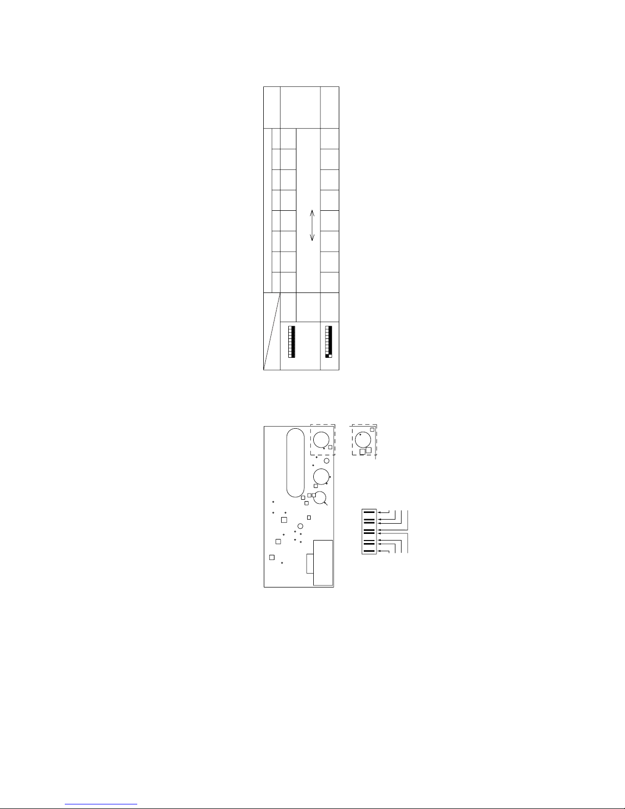
–39–
Function According to Switch Operation Switch Set Timing
When Off When On When Off When On
SWU 1 ~ 2
SW1
1 ~ 8
Refer to LED monitor display on the outdoor board.
9 ~ 10
SW2
1
2
3
4
5
6
7
8
9
10
SW3
1
2
3
4
5
6
7
8
9
10
SW4
1
2
3
4
5
6
7
8
9
10
Centralized control not
connected.
Storing of refrigeration
system connection
information.
Store IC•OC error history.
Ordinary control
-
Ordinary control
-
When the CS circuit is
closed, that time is totaled.
SW3-2 Function Invalid
Stop all indoor units.
– 8°C
7°C
Ordinary control
Ordinary control
Ordinary control
-
-
Model 400
SW4-3 Function invalid
Display variable capacity
unit operations.
2-phase modulation
Y Setting
-
-
-
-
[6] Function of Dip SW and Rotary SW
(1) Outdoor unit
PUHY-P600·650·700·750YSMF-B.
PUHY-P400·500YMF-B.
1 Variable capacity unit
MAIN board
Centralized control
connected.
Deletion of refrigeration
system connection
information.
Erase IC•OC error history.
• Refrigerant volume
adjustment operation.
• Ignore liquid level errors
-
Start forced defrosting.
-
Timer Reset
SW3-2 Function Valid
All indoor units test run
ON.
– 10°C
12°C
Evaporation temperature /
2°C lower than normal
Pump Down Operation
High pressure / 1.5 ~ 2.5 K
higher than normal
-
-
Model 500
SW4-3 Function valid
Display constant capacity
unit operations.
3-phase modulation
Super Y Setting
-
-
-
-
Changes as shown below by on → off change
0 %→3 %→6 %→9 %→12 %→ – 6 %→ – 3 %→0 %
Unit Address Setting
For self diagnosis/
operation monitoring
Centralized Control
Switch
Deletion of connection
information.
Deletion of error history.
• Adjustment of Refriger-
ant Volume
• Ignore liquid level errors
-
Forced defrosting
-
Reset of the time the CS
circuit is closed.
SW3-2 Function Valid/
Invalid
Indoor Unit Test Operation
Defrosting start temperature .
Defrosting end temperature.
Target low-pressure
change
Pump Down Function
Target high-pressure
change
-
-
Models
SW4-3 Function valid/
Invalid
Change service LED
Configuration compensation value
Inverter control
Switch Models
-
-
-
-
Switch Function
During normal
operation when
power is on.
Invalid 2 hours
after compressor
starts.
Before power is turned on.
-
Before power is turned on.
Before power is turned on.
During normal operation when
power is on.
-
-
-
During normal operation when
power is on.
During normal operation when
power is on.
When SW3-1 is ON after power is
turned on.
During normal operation when
power is on.
During normal operation when
power is on. (Except during
defrosting)
During normal operation when
power is on.
While the compressor is stopped.
During normal operation when
power is on.
-
When switching on the power.
When switching on the power.
During normal operation when
power is on.
When SW4-1 is ON
When switching on the power.
Before power is turned on.
-
-
-
-
During normal
operation when
power is on.
10 minutes or
more after
compressor
starts.
Set on 51 ~ 100 with the rotary switch.*2
Note 1: Factory setting is SWU 1 to 2 = 00, SW3 - 10 = set by model. All other switches are set to OFF.
Note 2: If the address is set from 01 to 50, it automatically becomes 100.
Note 3: Factory settings are SW4-6 = OFF, setting = Y.
When operating in Super Y mode, turn SW4-6 ON.
Page 43

–40–
2 Constant Capacity Unit
Function According to Switch Operation Switch Set Timing
When Off When On When Off When On
SWU 1 ~ 2
SW2
1
2
3
4
5
6
7
8
9
10
SW3
1
2
3
4
5
6
7
8
9
10
Note 1: Factory setting is SWU 1 to 2 = 00, SW3 - 10 = set by model. All other switches are set to OFF.
Note 2: If the address is set from 01 to 50, it automatically becomes 100.
-
-
-
Ignore liquid level errors
-
-
Start forced defrosting.
-
-
-
-
-
– 10°C
12°C
Ignore oil-equalization
circuit irregularities
-
-
-
R407C Model
Model 250
-
-
-
Ordinary control
-
-
Ordinary control
-
-
-
-
-
– 8°C
7°C
Ordinary control
-
-
-
R22 Model
Model 200
Before power is turned on.
-
-
During normal operation when
power is on.
-
-
-
-
-
-
During normal operation when
power is on.
During normal operation when power
is on. (Except during defrosting)
During normal operation when
power is on.
-
-
Before power is turned on.
When switching on the power.
Unit Address Setting
-
-
-
Ignore liquid level errors
-
-
Forced defrosting
-
-
-
-
Defrosting start temperature.
Defrosting end temperature.
Ignore oil-equalization
circuit irregularities
-
-
Models (Refrigerant)
Models (Capacity)
Switch Function
Set on 51 ~ 100 with the rotary switch.*2
During normal
operation when
power is on.
Invalid 2 hours
after compressor
starts.
Page 44

–41–
Centralized control not
connected.
Storing of refrigeration
system connection
information.
Store IC•OC error history.
Ordinary control
-
Ordinary control
-
Valid during normal
operation
SW3-2 Function Invalid
Stop all indoor units.
0°C
7°C
Ordinary control
Ordinary control
-
-
Model 400
Display variable capacity
unit operations.
-
2-phase modulation
Y Setting
-
-
-
-
When Off When On When Off When On
SWU 1 ~ 2
SW1
1 ~ 8
Refer to LED monitor display on the outdoor board.
9 ~ 10
SW2
1
2
3
4
5
6
7
8
9
10
SW3
1
2
3
4
5
6
7
8
9
10
SW4
1
2
3
4
5
6
7
8
9
10
Centralized control
connected.
Deletion of refrigeration
system connection
information.
Erase IC•OC error history.
• Refrigerant volume
adjustment operation.
• Ignore liquid level errors
-
Start forced defrosting.
-
note: 3
SW3-2 Function Valid
All indoor units test run
ON.
– 2°C
12°C
Evaporation temperature /
2°C lower than normal
High pressure / 1.5 ~ 2.5 K
higher than normal
-
-
Model 500
Display constant capacity
unit operations.
-
3-phase modulation
Super Y Setting
-
-
-
-
Unit Address Setting
For self diagnosis/
operation monitoring
Centralized Control
Switch
Deletion of connection
information.
Deletion of error history.
• Adjustment of Refriger-
ant Volume
• Ignore liquid level errors
-
Forced defrosting
-
Preserve suction pressure
SW3-2 Function Valid/
Invalid
Indoor Unit Test Operation
Defrosting start temperature .
Defrosting end temperature.
Target low-pressure
change
Target high-pressure
change
-
-
Models
Change service LED
-
Inverter control
Switch Models
-
-
-
-
Switch Function
During normal
operation when
power is on.
Invalid 2 hours
after compressor
starts.
PUHY-600·650·700·750 YSMF-B.
PUHY-400·500YMF-B.
1 Variable capacity unit
MAIN board
Function According to Switch Operation Switch Set Timing
Before power is turned on.
-
Before power is turned on.
Before power is turned on.
During normal operation when
power is on.
-
-
-
During normal operation when
power is on.
During normal operation when
power is on.
When SW3-1 is ON after power is
turned on.
During normal operation when
power is on.
During normal operation when
power is on. (Except during
defrosting)
During normal operation when
power is on.
During normal operation when
power is on.
-
When switching on the power.
During normal operation when
power is on.
When SW4-1 is ON
When switching on the power.
Before power is turned on.
-
-
-
-
During normal
operation when
power is on.
10 minutes or
more after
compressor
starts.
Set on 51 ~ 100 with the rotary switch.*2
Note 1: Factory setting is SWU 1 to 2 = 00, SW3 - 10 = set by model. All other switches are set to OFF.
Note 2: If the address is set from 01 to 50, it automatically becomes 100.
Note 3: The operation cumulative time of compressor is effective to it only within 1 hour.
Note 4: Factory settings are SW4-6 = OFF, setting = Y.
When operating in Super Y mode, turn SW4-6 ON.
Page 45

–42–
2 Constant Capacity Unit
Function According to Switch Operation Switch Set Timing
When Off When On When Off When On
SWU 1 ~ 2
SW2
1
2
3
4
5
6
7
8
9
10
SW3
1
2
3
4
5
6
7
8
9
10
Note 1: Factory setting is SWU 1 to 2 = 00, SW3 - 10 = set by model. All other switches are set to OFF.
Note 2: If the address is set from 01 to 50, it automatically becomes 100.
-
-
-
Ordinary control
-
-
Ordinary control
-
-
-
-
-
0°C
7°C
Ordinary control
-
-
-
R22 Model
Model 200
Before power is turned on.
-
-
During normal operation when
power is on.
-
-
-
-
-
-
During normal operation when
power is on.
During normal operation when power
is on. (Except during defrosting)
During normal operation when
power is on.
-
-
Before power is turned on.
When switching on the power.
-
-
-
Ignore liquid level errors
-
-
Start forced defrosting.
-
-
-
-
-
– 2°C
12°C
Ignore oil-equalization
circuit irregularities
-
-
-
R407C Model
Model 250
Unit Address Setting
-
-
-
Ignore liquid level errors
-
-
Forced defrosting
-
-
-
-
Defrosting start temperature.
Defrosting end temperature.
Ignore oil-equalization
circuit irregularities
-
-
Models (Refrigerant)
Models (Capacity)
Switch Function
Set on 51 ~ 100 with the rotary switch.*2
During normal
operation when
power is on.
Invalid 2 hours
after compressor
starts.
Page 46

–43–
(2) Indoor unit
DIP SW1, 3
Note 1: The shaded part indicates the setting at factory shipment. (For the SW not being shaded, refer to the
table below.)
Note 2: The DipSW setting is only effective during unit stopping (remote controller OFF) for SW1, 2, 3 and 4 commonly
and the power source is not required to reset.)
3: When both SW1-7 and SW1-8 are being set to ON, the fan stops at the heating thermostat of OFF.
Setting of DIP SW2
PLFY-P PEFY-P PDFY-P PFFY-P PCFY-P PKFY-P
VBM VLMD VKM VML VMH VM VLRM, VLEM VGM VAM VGM
Model
OFF ON OFF ON ON OFF ON OFF
OFF ON OFF
OFF ON OFF
ON OFF ON
ON OFF ON OFF ON OFF ON
OFF ON OFF
OFF ON OFF
Switch
SW1
SW3
3
6
7
3
4
6
8
Model P71 P80 P100 P125 P140 P200 P250
Capacity (model name) code
14 16 20 25 28 40 50
SW2 setting
Indoor unit inlet
None
100h
Ineffective
Fan output display
At stationary heating
Very low speed
SW1-7 setting
Ineffective
Ineffective
Heat pump
None
None
None
1st setting
Down blow B, C
–
Effective
–
–
Built in remote controller
Provided
2500h
Effective
Thermo. ON signal display
Always at heat.
Low speed
Set airflow
Effective
Effective
Cool.only
Provided
Provided
Provided
2nd setting
Horizontal
–
Ineffective
–
–
Room temp. sensor position
Clogged filter detect.
Filter duration
OA intake
Remote display select.
Humidifier control
Heating thermo. OFF airflow
Heating thermo. OFF airflow
Power failure automatic
return
Power source start/stop
Model selection
Louver
Vane
Vane swing function
Vane horizontal angle
Vane angle set for cooling
–
Heating 4deg up
–
–
Always ineffective for PKFY-P.VAM
Not provided for PKFY-P.VAM
Provided for PLFY-P.VGM (ON) setting
Always down blow B,C for PKFY-P.VAM
Horizontal (ON) setting for PLFY-P.VLMD
Ineffective (ON) setting for floor
standing
SW1
SW3
1
2
3
4
5
6
7
8
9
10
1
2
3
4
5
6
7
8
9
10
Switch SW name
Operation by SW
Switch set timing
OFF ON OFF ON
Remarks
At unit stopping
(at remote
controller OFF)
Model P20 P25 P32 P40 P50 P63
Capacity (model name) code
45 681013
SW2 setting
ON
OFF
ON
OFF
ON
OFF
ON
OFF
ON
OFF
ON
OFF
ON
OFF
ON
OFF
ON
OFF
ON
OFF
ON
OFF
Cooling capacity saving
for PKFY-P. VAM,
effective/ineffective
ON
OFF
ON
OFF
Page 47

–44–
Ceiling height
3 3.5 m
2 2.8 m
1 2.3 m
Setting of DIP SW4 Setting of DIP SW5
1234
ON OFF ON OFF
––––
ON OFF ON OFF
OFF OFF OFF ON
ON OFF OFF ON
OFF ON OFF ON
OFF OFF ON ON
––––
OFF OFF OFF –
ON ON ON –
OFF OFF OFF –
ON OFF OFF –
OFF OFF ON –
PMFY-P-DBM
PLFY-P-VLMD
PDFY-P20 ~ 80VM
PLFY-P40 ~ 63VKM
PLFY-P80 ~ 125VKM
PCFY-P-VGM
PKFY-P-VGM
PKFY-P-VAM
PFFY-P-VLEM, P-VLRM
PEFY-P20 ~ 32VML
PEFY-P40 ~ 140VMH
PEHY-P200·250VMH
PDFY-P100·125VM
Model Circuit board used
SW4
Switch Function Operation by switch Switch set timing
SWA
SWA
SWB
SWC
Ceiling height setting
For options
Setting of air outlet opening
Airflow control
(PLFY-P-VKM) (PCFY-P-VGM) (PDFY-P-VM)
(PLFY-P-VLMD)
(PLFY-P-VKM)
(PLFY-P-VKM, PCFY-P-VGM, PKFY-P-VGM)
(PLFY-P-VLMD)
(PDFY-P-VM)
Phase control
Relay selection
* The ceiling
height is
changed by
SWB setting.
* As this switch is used by interlocking with SWC,
refer to the item of SWC for detail.
SWA
SWB
123
2-way 3.5 m 3.8 m 3.8 m
3-way 3.0 m 3.3 m 3.5 m
4-way 2.7 m 3.0 m 3.5 m
* Set to the option to install the high efficiency
filter
Always after powering
Always after powering
Always after powering
Always after powering
3
1
2
2-way
4-way
3-way
Option
Standard
SWC
3
1
SWA
2
Option
Standard
SWC
3
1
SWA
2
3
1
2
3
1
2
3
1
2
220V
240V
Option
Standard
Page 48

–45–
33
33
3 TEST RUN
[1] Before Test Run
(1) Check points before test run
1 Neither refrigerant leak nor loose power source/ transmission lines should be found.
2 Confirm that the resistance between the power source terminal block and the ground exceeds 2MΩ by measuring
it with a DC 500 V megger. Do not run if it is lower than 2MΩ.
Note) Never apply the megger to the MAIN board. If applied, the MAIN board will be broken.
3 Confirm that the Ball valve at gas and liquid, oil balance sides is being fully opened.
Note) Certainly close the cap.
4 Be sure that the crankcase heater has been powered by turning the main power source on at least 12 hours
before starting the test run. The shorter powering time causes compressor trouble.
5 If any of the power supply wires (L1, L2, L3, N,
.) are mistakenly connected, it is possible to damage the unit.
Please exercise caution.
6 A transmission booster (RP) is required when the number of connected indoor unit models in a cooling system
exceeds the number of models specified in the chart below.
Note) The maximum number of units that can be controlled is determined by the indoor unit model, the type of
remote controller and their capabilities.
The number of indoor units and the total number of remote controllers is displayed within the parenthesis ( ).
(*1) If even one unit that is higher than 200 exists in the cooling system, the maximum capacity will be “200 or
higher”.
* Please refer to the installation manual for more details.
* Before turning power on to the outdoor unit, first turn on the transmission booster. (If the outdoor unit are mistakenly
turned on first, turn on the transmission booster and then reset the outdoor unit power.)
(2) Caution at inverter check
Because the inverter power portion in outdoor unit electrical part box have a lot of high voltage portion, be sure to follow
the instructions shown below.
During energizing power source, never touch inverter power portion because high voltage (approx. 580 V) is
applied to inverter power portion.
When checking,
Shut off main power source, and check it with tester, etc.
Allow 10 minutes after shutting off main power source.
Open the MAIN board mounting panel, and check whether voltage of both ends of electrolytic capacitor is
20 V or less.
1
2
1
2
3
200 or lower
200 or higher
Remote controller PAR-F 25MA
Prior to Ver. E After Ver. F
16 (32) 20 (40)
16 (32) 16 (32)
(*1)
Capability of the
connected indoor units
Remote controller type
Number of connected indoor units that
can be connected without a RP.
Page 49

–46–
(3) Check points for test run when mounting options
(4) Attention for mounting drain water lifting-up mechanism
Built-in optional parts Content of test run Check point Result
Mounting of drain
water lifting-up
mechanism
Mounting of permeable film humidifier
Release connector of pump circuit,
check error detection by pouring water
into drain pan water inlet.
After that, connect connector of
circuit.
Check pump operations and drainage
status in cooling (test run) mode.
Check humidifier operations and
water supply status in heating (test
run) mode.
Local remote controller displays code No.
“2503”, and the mechanism stops.
No overflow from drain pan.
Drain water comes out by operations of
drain pump.
Sound of pump operations is heard, and
drain water comes out.
No water leak from connecting portions
of each water piping.
Water is supplied to water supply tank,
and float switch is operating.
Work Content of test run Check point Result
Disassembling and
assembling of drain
water lifting-up
mechanism
Mounting of float
switch
Electric wiring
Lead wire from control box not
damaged.
Rubber cap properly inserted to drain
water outlet of drain pan?
Insulation pipe of gas and liquid pipes
dealt with as shown in the right
figure?
Drain pan and piping cover mounted
without gap?
Drain pan hooked on cut projection of
the mechanism?
Float switch installed without contacting
with drain pan?
No mistakes in wiring?
Connectors connected surely and
tightly?
No tension on lead wire when sliding
control box?
No gap
Float switch moves smoothly.
Float switch is mounted on mounting board straightly without deformation.
Float switch does not contact with
copper pipe.
Wiring procedure is exactly followed.
Connector portion is tightly hooked.
1
2
3
1
2
3
4
5
1
2
3
1
2
3
Insulation pipe
Page 50

–47–
Page 51

–48–
(5) Check points for system structure
In the case of the PUHY-(P) 400·500 YMF-B
Check points from installation work to test run.
Classification Portion Check item Trouble
Installation
and piping
Power source
wiring
1
2
3
4
5
6
7
8
9
1
2
Instruction for selecting combination of outdoor unit, and
indoor unit followed? (Maximum number of indoor units
which can be connected, connecting model name, and
total capacity.)
Follow limitation of refrigerant piping length? For example, 100 m or less (total length: 220 m) at the farthest.
Connecting piping size of branch piping correct?
Branch pipe properly selected?
Refrigerant piping diameter correct?
Refrigerant leak generated at connection?
Insulation work for piping properly done?
Specified amount of refrigerant replenished?
Pitch and insulation work for drain piping properly done?
Specified switch capacity and wiring diameter of main
power source used?
Proper grounding work done on outdoor unit?
Not operate.
Not cool (at cooling).
Not heat (at heating).
Not cool, not heat, error stop.
Condensation drip in piping.
Not cool, not heat, error stop.
Water leak, condensation drip in
drain piping.
Error stop, not operate.
Page 52

–49–
Classification Portion Check item Trouble
Transmission
line
System set
Before starting
Limitation of transmission line length followed? For
example, 200 m or less (total length: 500 m) at the farthest.
1.25 mm2 or more transmission line used?
(Remote controller 10 m or less 0.75 mm
2
)
2-core cable used for transmission line?
Transmission line apart from power source line by 5 cm
or more?
One refrigerant system per transmission line?
The short circuit connector is changed form CN41 to
CN40 on the MAIN board when the system is centralized
control? (Just one outdoor unit. Not all outdoor units.)
No connection trouble in transmission line?
Address setting properly done? (Remote controller,
indoor unit and outdoor unit.)
Setting of address No. done when shutting off power
source?
Address numbers not duplicated?
Turned on SW3-8 on indoor unit circuit board when
mounting room thermistor sensor?
Refrigerant piping ball valve (Liquid pressure pipe, gas
pressure pipe) opened?
Turn on power source 12 hours before starting operations?
Erroneous operation, error stop.
Erroneous operation, error stop.
Error stop in case multiple-core
cable is used.
Erroneous operation, error stop.
Not operate.
Not operate.
Error stop or not operate.
Error stop or not operate.
Can not be properly set with power
source turned on.
Not operate.
Set temperature not obtained at heating
operations. (Thermostat stop is difficult.)
Error stop.
Error stop, compressor trouble.
1
2
3
4
5
6
7
1
2
2
3
4
1
Page 53

–50–
Power
source
for
outdoor
unit
Switch
Switch
MAIN board
Outdoor unit
2
1
1
6
12345
1
6
2157
8
2
In the case of the PUHY-(P) 600·650·700·750 YSMF-B
Check points from installation work to test run.
Classification Portion Check item Trouble
Installation
and piping
Power source
wiring
1
2
3
4
5
6
7
8
9
1
2
Instruction for selecting combination of outdoor unit, and
indoor unit followed? (Maximum number of indoor units
which can be connected, connecting model name, and
total capacity.)
Follow limitation of refrigerant piping length? For example, 100 m or less (total length: 220 m) at the farthest.
Connecting piping size of branch piping correct?
Branch pipe properly selected?
Refrigerant piping diameter correct?
Refrigerant leak generated at connection?
Insulation work for piping properly done?
Specified amount of refrigerant replenished?
Pitch and insulation work for drain piping properly done?
Specified switch capacity and wiring diameter of main
power source used?
Proper grounding work done on outdoor unit?
Not operate.
Not cool (at cooling).
Not heat (at heating).
Not cool, not heat, error stop.
Condensation drip in piping.
Not cool, not heat, error stop.
Water leak, condensation drip in
drain piping.
Error stop, not operate.
* Limitations apply when 17 or more indoor units are connected. Please refer to the installation manual.
Page 54

–51–
Classification Portion Check item Trouble
Transmission
line
System set
Before starting
Limitation of transmission line length followed? For
example, 200 m or less (total length: 500 m) at the farthest.
1.25 mm2 or more transmission line used?
(Remote controller 10 m or less 0.75 mm
2
)
2-core cable used for transmission line?
Transmission line apart from power source line by 5 cm
or more?
One refrigerant system per transmission line?
The short circuit connector is changed form CN41 to
CN40 on the MAIN board when the system is centralized
control? (Just one outdoor unit. Not all outdoor units.)
No connection trouble in transmission line?
Address setting properly done? (Remote controller,
indoor unit and outdoor unit.)
Setting of address No. done when shutting off power
source?
Address numbers not duplicated?
Turned on SW3-8 on indoor unit circuit board when
mounting room thermistor sensor?
Refrigerant piping ball valve (Liquid pressure pipe, gas
pressure pipe, oil balance pipe) opened?
Turn on power source 12 hours before starting operations?
Erroneous operation, error stop.
Erroneous operation, error stop.
Error stop in case multiple-core
cable is used.
Erroneous operation, error stop.
Not operate.
Not operate.
Error stop or not operate.
Error stop or not operate.
Can not be properly set with power
source turned on.
Not operate.
Set temperature not obtained at heating
operations. (Thermostat stop is difficult.)
Error stop.
Error stop, compressor trouble.
1
2
3
4
5
6
7
1
2
2
3
4
1
Page 55

–52–
[2] Test Run Method
Note) 1. If check code is displayed on remote controller or remote controller does not operate normally.
2. Test run automatically stops operating after two hours by activation of timer set to two hours.
3. During test run, test run remaining time is displayed on time display section.
4. During test run, temperature of liquid pipe in indoor unit is displayed on remote controller room temperature
display section.
5. When pressing
adjust button, depending on the model, “NOT AVAILABLE” may be displayed on remote
controller. However, it is not a malfunction.
6. When pressing
or button, depending on the model, “NOT AVAILABLE” may be displayed on
remote controller. However, it is not a malfunction.
Operation procedure
1
2
3
4
5
6
7
8
9
Turn on universal power supply at least 12 hours before getting started → Displaying “HO” on display panel for
about two minutes
Press
TEST RUN
button twice → Displaying “TEST RUN’’ on display panel
Press
selection button → Make sure that air is blowing out
Press
select button to change from cooling to heating operation, and vice versa → Make sure that
warm or cold air is blowing out
Press adjust button → Make sure that air blow is changed
Press
or button to change wind → Make sure that horizontal or downward blow is adjustable
Make sure that indoor unit fans operate normally
Make sure that interlocking devices such as ventilator operate normally if any
Press
ON/OFF
button to cancel test run → Stop operation
Page 56

–53–
44
44
4 GROUPING REGISTRATION OF INDOOR UNITS WITH REMOTE CONTROLLER
(1) Switch function
• The switch operation to register with the remote controller is shown below:
Registration/
ordinary mode
selector switch
Registration/ordinary
mode selection switch
Switch to assign indoor
unit address
Registration switch
Confirmation switch
Delete switch
Registered mode
selector switch
Switch to assign
interlocked unit address
A + B
C
D
E
F
G
H
This switch selects the ordinary mode or registered mode (ordinary
mode represents that to operate indoor units).
* To select the registered mode, press the
FILTER
+ switch
continuously for over 2 seconds under stopping state.
Note) The registered mode can not be obtained for a while after
powering.
Pressing the
FILTER
+ switch displays “CENTRALLY
CONTROLLED”.
This switch assigns the unit address for “INDOOR UNIT ADDRESS
NO.”
This switch is used for group/interlocked registration.
This switch is used to retrieve/identify the content of group and interlocked (connection information) registered.
This switch is used to retrieve/identify the content of group and interlocked (connection information) registered.
This switch selects the case to register indoor units as group (group
setting mode) or that as interlocked (interlocked setting mode).
* The unit address is shown at one spot for the group setting mode
while at two spots for the interlocked setting mode.
This switch assigns the unit address of “OA UNIT ADDRESS NO.”
Symbol
of switch
ON/OFF
–
STAND BY
DEFROST
INDOOR UNIT
ADDRESS NO.
ERROR CODE
OA UNIT ADDRESS NO.
CENTRALLY CONTROLLED
CLOCK
ON OFF
˚C
1Hr.
NOT AVAILABLE
˚C
CHECK MODE
FILTER
CHECK
TEST RUN
ON OFFCLOCK
FILTER
CHECK
TEST RUN
REMOTE CONTROLLER
NETWORK
PAR-F25MA
TEMP. TIMER SET
F Delete switch
G Registered mode
selector switch
E Confirmation switch
C Switch to assign
indoor unit address
H Switch to assign inter-
locked unit address
D Registration switch
A
B
+
FILTER
TEST RUN
CLOCK
ON OFF
Name Name of actual switch Description
of TEMP
of TIMER SET
Page 57

–54–
(2) Attribute display of unit
• At the group registration and the confirmation/deletion of registration/connection information, the type (attribute) of the
unit is displayed with two English characters.
Display Type (Attribute) of unit/controller
Indoor unit connectable to remote controller
Outdoor unit (PUHY-(P)400/500YMF-B)
Outdoor unit (PUHN-(P)200/250YMF-B)
Local remote controller
System controller (MJ)
[Description of registration/deletion/retrieval]
• The items of operation to be performed by the remote controller are given below. Please see the relating paragraph for
detail.
1 Group registration of indoor unit
• The group of the indoor units and operating remote controller is registered.
• It is usually used for the group operation of indoor units with different refrigerant system.
2 Retrieval/identification of group registration information of indoor units
• The address of the registered indoor units in group is retrieved (identified).
3 Retrieval/identification of registration information
• The connection information of any unit (indoor/outdoor units, remote controller or the like) is retrieved (identified).
4 Deletion of group registration information of indoor units
• The registration of the indoor units under group registration is released (deleted).
5 Deletion of the address not existing
• This operation is to be conducted when “6607” error (No ACK error) is displayed on the remote controller caused by
the miss setting at test run, or due to the old memory remained at the alteration/modification of the group composition.
Caution:
When MELANS (MJ-103MTRA for example) is being connected, do not conduct the group/pair registration using
the remote controller. The group/pair registration should be conducted by MELANS. (For detail, refer to the instruction exclusively prepared for MELANS.)
Page 58

–55–
(3) Group registration of indoor unit
1) Registration method
• Group registration of indoor unit ................. 1
The indoor unit to be controlled by a remote controller is registered on the remote controller.
[Registration procedure]
1 With the remote controller under stopping or at the display of “HO”, continuously press the
FILTER
+
switch (A + B) at the same time for 2 seconds to change to the registration mode. (See the figure below.)
2 Assign the indoor unit address to “INDOOR UNIT ADDRESS NO.” by operating the (Room temperature
adjustment) (C).
Then press the
TEST RUN
switch (D) to register. In the figure below, the “INDOOR UNIT ADDRESS NO.” is being
set to 001.
3 After completing the registration, press the
FILTER
+ switch (A + B) at the same time for 2 seconds to
change to the original ordinary mode (with the remote controller under stopping).
• Remote controller under stopping • “HO” under displaying
Ordinary mode
INDOOR UNIT
ADDRESS NO
ERROR CODE
OA UNIT ADDRESS NO
˚C
INDOOR UNIT
ADDRESS NO
ERROR CODE
OA UNIT ADDRESS NO
˚C
INDOOR UNIT
ADDRESS NO
ERROR CODE
OA UNIT ADDRESS NO
˚C
1
1
Group setting mode
• Confirm the indoor unit address No.
• Confirm the connection of the transmission line.
ON/OFF
–
STAND BY
DEFROST
ERROR CODE
OA UNIT ADDRESS NO.
CENTRALLY CONTROLLED
CLOCK
ON OFF
˚C
1Hr.
NOT AVAILABLE
˚C
CHECK MODE
FILTER
CHECK
TEST RUN
ON OFFCLOCK
FILTER
CHECK
TEST RUN
REMOTE CONTROLLER
NETWORK
PAR-F25MA
TEMP. TIMER SET
INDOOR UNIT
ADDRESS NO.
INDOOR UNIT
ADDRESS NO
ERROR CODE
OA UNIT ADDRESS NO
˚C
INDOOR UNIT
ADDRESS NO
ERROR CODE
OA UNIT ADDRESS NO
˚C
• Registration complete
• Registration error
Indicates the type of unit
(Indoor unit in this case)
“88” flickers indicating registration error. (when the indoor unit
registered is not existing)
2 Assign the
address (C)
1 Change to the
registration
mode (A + B)
3 Press the
registration
switch (D)
Remote controller
▲
▼
System example
Indoor units
Group
2 + 3
Page 59

–56–
2) Method of retrieval/confirmation
• Retrieval/confirmation of group registration information on indoor unit............... 2
The address of the indoor unit being registered on the remote controller is displayed.
[Operation procedure]
1 With the remote controller under stopping or at the display of “HO”, continuously press the
FILTER
+ switch (A
+ B) at the same time for 2 seconds to change to the registration mode.
2 In order to confirm the indoor unit address already registered, press
switch (E). (See figure below.) When the group
of plural sets is registered, the addresses will be displayed in order at each pressing of switch (E).
3 After completing the registration, continuously press the
FILTER
+ switch (A + B) at the same time for 2
seconds to change to the original ordinary mode (with the remote controller under stopping).
• Retrieval/confirmation of registration information ................. 3
The registered information on a certain unit (indoor unit, outdoor unit, remote controller or the like) is displayed.
[Operation procedure]
1 With the remote controller under stopping or at the display of “HO”, continuously press the
FILTER
+ switch (A
+ B) at the same time for 2 seconds to change to the registration mode.
2 Operate
switch (G) for the interlocked setting mode. (See figure below.)
3 Assign the unit address of which registration information is desired to confirm with the (TIMER SET) switch
(H). Then press the
switch (E) to display it on the remote controller. (See figure below.)
Each pressing of switch (E) changes the display of registered content. (See figure below.)
4 After completing the retrieval/confirmation, continuously press the
FILTER
+ switch (A + B) at the same time
for 2 seconds to change to the original ordinary mode (with the remote controller under stopping).
• Registered
• No registration
ON/OFF
–
STAND BY
DEFROST
ERROR CODE
OA UNIT ADDRESS NO.
CENTRALLY CONTROLLED
CLOCK
ON OFF
˚C
1Hr.
NOT AVAILABLE
˚C
CHECK MODE
FILTER
CHECK
TEST RUN
ON OFFCLOCK
FILTER
CHECK
TEST RUN
REMOTE CONTROLLER
NETWORK
PAR-F25MA
TEMP. TIMER SET
INDOOR UNIT
ADDRESS NO.
INDOOR UNIT
ADDRESS NO
ERROR CODE
OA UNIT ADDRESS NO
˚C
INDOOR UNIT
ADDRESS NO
ERROR CODE
OA UNIT ADDRESS NO
˚C
▲
▼
1 Press the switch for confirmation (E)
Note: Only one address will be displayed
when the registration is one even the
switch is how often pressed
Indicates the type of unit
(Indoor unit in this case)
1
1
Page 60

–57–
3) Method of deletion
• Deletion of group registration information of indoor unit ................. 4
[Operation procedure]
1 With the remote controller under stopping or at the display of “HO”, continuously press the
FILTER
+
switch (A + B) at the same time for 2 seconds to change to the registration mode.
2 Press the switch (E) to display the indoor unit address registered. (As same as 2)
3 In order to delete the registered indoor unit being displayed on the remote controller, press the
CLOCK ON OFF
(F) switch two
times continuously. At completion of the deletion, the attribute display section will be shown as “ – – “.
(See figure below.)
Note: Completing the deletion of all indoor units registered on the remote controller returns to “HO” display.
4 After completing the registration, continuously press the
FILTER
+ switch (A + B) at the same time for 2
seconds to change to the original ordinary mode (with the remote controller under stopping).
ON/OFF
–
STAND BY
DEFROST
INDOOR UNIT
ADDRESS NO.
ERROR CODE
OA UNIT ADDRESS NO.
CENTRALLY CONTROLLED
CLOCK
ON OFF
˚C
1Hr.
NOT AVAILABLE
˚C
CHECK MODE
FILTER
CHECK
TEST RUN
ON OFFCLOCK
FILTER
CHECK
TEST RUN
REMOTE CONTROLLER
NETWORK
PAR-F25MA
TEMP. TIMER SET
INDOOR UNIT
ADDRESS NO
ERROR CODE
OA UNIT ADDRESS NO
˚C
ON/OFF
–
STAND BY
DEFROST
ERROR CODE
OA UNIT ADDRESS NO.
CENTRALLY CONTROLLED
CLOCK
ON OFF
˚C
1Hr.
NOT AVAILABLE
˚C
CHECK MODE
FILTER
CHECK
TEST RUN
ON OFFCLOCK
FILTER
CHECK
TEST RUN
REMOTE CONTROLLER
NETWORK
PAR-F25MA
TEMP. TIMER SET
INDOOR UNIT
ADDRESS NO.
INDOOR UNIT
ADDRESS NO
ERROR CODE
OA UNIT ADDRESS NO
˚C
INDOOR UNIT
ADDRESS NO
ERROR CODE
OA UNIT ADDRESS NO
˚C
ON/OFF
–
1 Set the address
2 Press the switch for
confirmation (E)
• Registered
• No registration
* Same display will appear when
the unit of “007” is not existing.
1 Press the switch for confirmation (F)
twice continuously
• Deletion completed
• Deletion completed
In case group registration with other
indoor unit is existing
In case no group
registration with other
indoor unit is existing
▲
▼
1
1
▼
▲
1 + 2
“– –” indicates the
deletion completed.
INDOOR UNIT
ADDRESS NO
ERROR CODE
OA UNIT ADDRESS NO
˚C
INDOOR UNIT
ADDRESS NO
ERROR CODE
OA UNIT ADDRESS NO
˚C
(Alternative
display)
INDOOR UNIT
ADDRESS NO
ERROR CODE
OA UNIT ADDRESS NO
˚C
INDOOR UNIT
ADDRESS NO
ERROR CODE
OA UNIT ADDRESS NO
˚C
(Alternative
display)
INDOOR UNIT
ADDRESS NO
ERROR CODE
OA UNIT ADDRESS NO
˚C
2
Page 61

–58–
4) Deletion of information on address not existing
• Deletion of information on address not existing ................. 5
This operation is to be conducted when “6607” error (No ACK error) is displayed on the remote controller caused by
the miss setting at test run, or due to the old memory remained at the alteration/modification of group composition,
and the address not existing will be deleted.
Note : The connection information (connection between indoor unit and outdoor unit) on the refrigerant system can
not be deleted.
An example to delete the system controller of “250” from the indoor unit of “007” is shown below.
[Operation procedure]
1 With the remote controller under stopping or at the display of “HO”, continuously press the
FILTER
+ switch (A
+ B) at the same time for 2 seconds to change to the registration mode.
2 Operate
switch (G) for the interlocked setting mode ( ii ). (See the figure below.)
3 Assign the unit address existing to “OA UNIT ADDRESS No.” with the (Room temperature control) switch (C),
and press switch (E) to call the address to be deleted. (See the figure below.) As the error display on the remote
controller is usually transmitted from the indoor unit, “OA UNIT ADDRESS No.” is used as the address of the indoor unit.
4 Press the
CLOCK
ON
OFF
switch (F) twice. (See the figure below.)
5 After completing the deletion, continuously press the
FILTER
+ switch (A + B) at the same time for 2 seconds
to return to the original ordinary mode (with the remote controller under stopping).
INDOOR UNIT
ADDRESS NO
ERROR CODE
OA UNIT ADDRESS NO
˚C
INDOOR UNIT
ADDRESS NO
ERROR CODE
OA UNIT ADDRESS NO
˚C
(Alternative
display)
INDOOR UNIT
ADDRESS NO
ERROR CODE
OA UNIT ADDRESS NO
˚C
INDOOR UNIT
ADDRESS NO
ERROR CODE
OA UNIT ADDRESS NO
˚C
(Alternative
display)
ON/OFF
–
STAND BY
DEFROST
INDOOR UNIT
ADDRESS NO.
ERROR CODE
OA UNIT ADDRESS NO.
CENTRALLY CONTROLLED
CLOCK
ON OFF
˚C
1Hr.
NOT AVAILABLE
˚C
CHECK MODE
FILTER
CHECK
TEST RUN
ON OFFCLOCK
FILTER
CHECK
TEST RUN
REMOTE CONTROLLER
NETWORK
PAR-F25MA
TEMP. TIMER SET
INDOOR UNIT
ADDRESS NO
ERROR CODE
OA UNIT ADDRESS NO
˚C
INDOOR UNIT
ADDRESS NO
ERROR CODE
OA UNIT ADDRESS NO
˚C
(Alternative
display)
▲
▲
▼
When both indoor
unit and interlocked
unit addresses are
existing
Deletion of
address not
existing
1 Set the address (H)
3 Press the deletion switch (F) twice
• Deletion completed
• Deletion completed
1 + 2
3
3
2 Press the switch for
confirmation (E)
Page 62

–59–
55
55
5 CONTROL
[1] Control of Outdoor Unit
[1]- 1 PUHY-P400·500 YMF-B
(1) Initial processing
• When turning on power source, initial processing of microcomputer is given top priority.
• During initial processing, control processing corresponding to operation signal is suspended. The control processing
is resumed after initial processing is completed. (Initial processing: Data processing in microcomputer and initial
setting of each LEV opening, requiring approx. 2 minutes at the maximum.)
(2) Control at staring
• For 3 minutes after starting, 60 Hz is the upper frequency limit. (When only No. 1 compressor is operating.)
• 75 Hz is the upper limit within 2 hours after the power supply has been turned ON and for the 30 minutes after the
compressor has started operation.
• Normal control is performed after the initial start mode (described later) has been completed.
(3) Compressor capacity control
• Variable capacitor compressor is performed by the variable capacity compressor (No. 1: inverter motor) and
constant capacity compressor (No. 2: It has capacity control switching).
• In response to the required performance, the number of compressors operating, the switching of capacity control
and the frequency of the variable capacitor compressor is controlled so that the evaporation temperature is
between – 2 and – 6°C in cooling mode and that the condensation temperature is 49°C in heating mode.
• The fluctuation of the frequency of the variable capacitor compressor is as follows. It is performed at 2 Hz per
second.
20 to 100 Hz (TH6 > 20°C and in cooling mode, or in heating mode)
30 to 100 Hz (TH6 < 20°C and in cooling mode)
1) No. 2 compressor operation, stopping and full-load/un-load switching
1 Switching from stopping to operation of No. 2 compressor.
When the required performance cannot be obtained by only No. 1 compressor, the No. 2 compressor will be
started. (The No. 2 compressor will be started in un-load operation.)
• After the No. 1 compressor has reached 100 Hz, the No. 2 compressor stops → un-load or un-load → full-load.
2 Switching from operation to stopping of No. 2 compressor.
When the required performance is exceeded when the two compressors, No. 1 and No. 2, are operating, the No.
2 compressor is stopped or performed in un-load operation.
3 Switching from un-load to full-load of No. 2 compressor
When the required performance cannot be obtained by the No. 1 compressor and the No. 2 compressor operating in un-load, the No. 2 compressor will be switched to full-load operation.
4 Switching from full-load to un-load of No. 2 compressor
When the required performance is exceeded when the two compressors, No.1 and No. 2 operating in full-load,
the No 2 compressor will be switched to un-load operation.
2) Pressure control
The upper limit value for the high pressure (Pd) has been set for each frequency. When this value is exceeded, the
frequency is reduced every 30 seconds.
3) Discharge temperature control
The discharge temperature of the compressor (Td) is monitored during the operation. If the upper limit is exceeded, the
frequency is reduced by 5 Hz.
• Control is performed every 30 seconds after 30 seconds at the compressor starting.
Page 63

–60–
• The operating temperature is 124°C (No. 1 compressor) or 115°C (No. 2 compressor).
4) Compressor frequency control
1 Ordinary control
The ordinary control is performed after the following times have passed.
• 30 seconds after the start of the compressor or 30 seconds after the completion of defrosting.
• 30 seconds after frequency control operation by the discharge temperature or the high pressure.
2 Amount of frequency fluctuation
The amount of frequency fluctuation is controlled in response to the evaporation temperature (Te) and the
condensation temperature (Tc) so that it will be approached the target values.
3 Frequency control back-up by the bypass valve
Frequency control is backed-up by the turning on (opening) the bypass valve (SV4) when only the No. 1 compressor is operated at its lowest frequency.
• Cooling
After the compressor has been operated for 15 minutes and only the No. 1 compressor is operated in un-load
(its lowest frequency), the bypass valve is turned ON when the low pressure (63 LS) is 1.0 kg/cm
2
G (0.098
MPa) or less and turned OFF when it is 2.0 kg/cm
2
G (0.196 MPa) or more.
• Heating
After the compressor has been operated for 3 minutes and only the No. 1 compressor is operated in un-load
(its lowest frequency), the bypass valve is turned ON when the high pressure (Pd) exceeds 27 kg/cm
2
(2.65
MPa) and turned OFF when it is 24 kg/cm
2
(2.35 MPa) or less.
(4) Bypass - capacity control
The solenoid valves have bypass valves (SV1, SV4 and SV6) that allow bypassing of the high pressure and low
pressure sides and solenoid valves (SV22 and SV32) that control the capacity control valve inside the compressor.
They operate as follows.
1) Bypass valve (SV6) [SV6 is on (open)]
• As shown in the table below, control is performed by the operation and stopping of the No. 1 compressor and No. 2
compressor.
No. 1 compressor No. 2 compressor SV6
Stop Stop OFF
Operate Stop ON
Operate Operate OFF
ON
OFF
1.0 kg/cm
2
G
(0.098 MPa)
2.0 kg/cm
2
G
(0.196 MPa)
24 kg/cm2G
ON
OFF
27 kg/cm2G
(2.35 MPa) (2.65 MPa)
Page 64

–61–
Item
At compressor is started
Compressor stopped during cooling or heating mode
After operation has been stopped
During defrosting ((*1) in Fig below)
During oil recovery operation
When low pressure (Ps) has
dropped during lower limit frequency operation(15 minutes after start)
When the high pressure (Pd) is
risen up during lower limit frequency operation (3 minutes after
starting)
When the discharge temperature
(Td) is risen up
Ps 2.0 kg/cm2G
(0.196 MPa)
Pd
24 kg/cm2G
(2.35 MPa) and after
30 seconds
Pd
20 kg/cm2G
(1.96 MPa)
* Example of operation of SV1
Compressor
Bypass
solenoid
valve (SV1)
(4-minute)
(2-minute) (4-minute) (3-minute)
Start
Thermo.
OFF
Thermo.
ON
Defrost
Stop
2) Bypass solenoid valves (SV1, SV4) [Both SV1 and SV4 are on (open)]
ON OFF
SV1
ON for 4 minutes
ON
ON for 3 minutes
ON
ON during oil recovery operation after continuous low-frequency compressor operation.
—
—
—
ON
Ps < 1.0 kg/cm
2
G
(0.098 MPa)
Pd 27 kg/cm2G
(2.65 MPa)
ON when the high pressure (Pd) exceeds the
control pressure limit.
OFF
SV4
—
—
—
Normally ON
—
3) Capacity control solenoid valve (SV22, SV32).
• Operation of solenoid valve
• SV22 and SV32 stand for SV2 and SV3 of the No. 2
compressor.
Solenoid valve
SV22
SV32
COMP
SV22 SV32
Coil Valve Coil Valve
OFF Open OFF Closed
ON Closed ON Open
Status
Full-load
(Operating at 100 %
capacity)
Un-load
(Capacity control
operation)
Pd 27.5 kg/cm2G
(2.70 MPa)
Pd 24 kg/cm2G
(2.35 MPa) and
after 30 seconds.
130°C
(No. 1 compressor)
115°C
(No. 2 compressor)
• Td
>
and
•
Pd > 20 kg/cm2G
(1.96 MPa)
or
Ps < 3.5 kg/cm
2
G
(0.34 MPa)
115°C
(No. 1 compressor)
100°C
(No. 2 compressor)
Td
Page 65

–62–
(5) Oil return control (Electronic expansion valve (SLEV))
• The amount of opening of the oil-return LEV (SLEV) is determined as follows: in cooling, by the operating capacity
of the No. 1 compressor and the ambient temperature; in heating, by the operating capacity of the No. 1 compressor.
• It is opened (64) when both compressors are stopped and started for 10 minutes. (Upper limit of LEV opening is So
= 388 pulse.)
• SLEV = 0 when the No. 1 compressor is stopped.
(6) Sub-cool coil control (Electronic expansion valve (LEV1))
• The sub-cool coil control provides control every 30 seconds to keep the super heat volume from the temperature of
the inlet/outlet of the sub-cool coil (TH8, TH9) within a stable range (2 to 4 degrees).
• It controls by correcting the amount of opening according to the temperature of the inlet/outlet of the sub-cool coil
(TH5, TH7), the high pressure (Pd) and discharge temperature.
• It is closed (0) in heating or when the compressor is stopped.
• It has a fixed opening (480) in defrosting.
• During normal control, the operating range is 46 to 480.
(7) Defrosting control
1) Start of defrosting
• After there has been heating operation for 50 minutes or after 90 minutes has passed and a piping temperature
(TH5) of – 8°C or less is detected for a preset time, defrosting begins.
• When 10 minutes has passed since the compressor began operation or if 10 minutes has passed since recovery
from defrosting, setting the forced defrosting switch (Dip SW2-7) to starts forced defrosting.
2) End of defrosting
• Defrosting ends when 15 minutes have passed since the start of defrosting, or when a piping temperature (TH5) of
7°C or more is detected for 2 minutes or longer. (Note that if the defrost-prohibited time is set on 90 minutes, the
defrost-prohibit time will be 50 minutes following a 15-minute timed recovery.
• Ending the defrosting is prohibited for 2 minutes after the start of defrosting. (Note that the defrosting operation will
be ended if the piping temperature exceeds 20°C within 2 minutes of the start of defrosting.
3) Defrost-prohibit
• Defrosting is not performed for 10 minutes after the start of compressor operation and during oil recovery mode.
4) Abnormalities during defrosting
• If an error is detected during defrosting, the defrosting is stopped and the defrost-prohibit time is set to 20 minutes
by the compressor cumulative operating time.
Page 66

–63–
5) Change in number of operating indoor units while defrosting
• If the number of indoor units changes while the outdoor unit is defrosting, the defrosting operation continues. Once
defrosting has ended, control for changing the number of units is performed.
• If the indoor unit is stopped while the outdoor unit is defrosting or if the thermostat is set to off, the defrosting
operation continues. Once defrosting has ended, the unit is stopped.
6) Number of compressors operating during defrosting
• The number of compressors operating during defrosting is always two.
(8) Control of liquid level detecting heater
Detect refrigerant liquid level in accumulator, and heat refrigerant with liquid level heater for judging refrigerant amount.
7 steps of duty control is applied to liquid level heater depending on frequency and outdoor air temperature, 1 minute
after starting compressor.
(9) Judgement and control of refrigerant amount
• Judge refrigerant amount by detecting refrigerant liquid surface accumulator.
1) Judgement of accumulator liquid level
• Return refrigerant from accumulator liquid level detecting circuit to compressor inlet pipe, detect piping temperature, and judge liquid level.
When heated with heater, liquid refrigerant temperature is almost equal to low pressure saturation temperature,
and gas refrigerant temperature is a little higher than low pressure saturation temperature. By comparing these
temperatures A in accumulator inlet portion, refrigerant liquid level can be judged.
Accumulator liquid level is judged in 3 steps as shown in the figure, from temperature A and liquid level detecting
temperatures (TH3, TH4). After deciding refrigerant status (Liquid: TH3 and TH4 are TH2 + 9°C or less, Gas: TH3
and TH4 are TH2 + 9°C or more), judge liquid level by comparing TH3 and TH4.
2) Control of liquid level detection
1 Prohibition of liquid level detection
Liquid level is detected in normal conditions except for the following;
(Cooling)
• For 6 minutes after starting unit, and during unit stopping.
(Heating)
• For 6 minutes after starting unit, and during unit stopping.
• During defrosting.
• For 10 minutes after refrigerant recovery.
(Note that liquid level determination is being performed even when liquid level detection is being disregarded.)
2 In case AL = 2 is detected for 3 consecutive minutes during liquid level detection (control at excessive refrigerant
replenishment and trouble mode)
• Changed to intermittent fault check mode preceded by 3 minutes restart prevention. But it is not abnormal when
the discharge SH is high. Error stop is observed when trouble is detected again in the same intermittent fault
check mode (for 30 minutes after unit stops for intermittent fault check).
• When turning on liquid level trouble ignore switch (SW2-4), error stop is not observed, and 3 minutes restart
prevention by intermittent fault check mode is repeated. However, LED displays overflow.
(Turning SW2-4 on makes the error of TH6 < outdoor air sensor > ineffective.)
3 When operation mode shows “Stop,” excessive or insufficient refrigerant display and excessive or insufficient
refrigerant ignore display are extinguished.
TH3
TH4
Balance pressure pipe
TH2
AL=0
AL=1
AL=2
Dividing plate
Outlet
pipe
Inlet pipe
• Judgement by the AL is at best only a
rough guideline.
Please do not add refrigerant based
on the AL reading alone.
*Temperature A: low pressure saturation temperature
(TH2).
Page 67

–64–
(10) Refrigerant recovery control
Refrigerant recovery is conducted to prevent refrigerant from accumulating in the stopped unit (fan unit), the unit under
cooling mode and that with heating thermostat being turned off.
1) Start of refrigerant recovery
1 Refrigerant recovery is started when the two items below are fully satisfied.
• 30 minutes has passed after finishing refrigerant recovery.
• The level detector detects AL = 0 for 3 minutes continuously, or the discharge SH is high.
2) Refrigerant recovery operation
• Refrigerant is recovered by opening LEV of the objective indoor units (indoor units under stop. fan, and cooling
modes, and that with heating thermostat being turned off) for 30 seconds.
• The regular capacity control of the outdoor unit and the regular LEV control of the indoor unit are not applied during
refrigerant recovery operation, but are fixed with the value before the recovery operation. These controls will be
conducted one minute after finishing the recovery operation.
• Defrosting operation is prohibited during the recovery operation, and it will be conducted after finishing the recovery
operation
(11) Outdoor unit heat exchanger capacity control
1) Control method
• In order to stabilize the evaporation temperature during cooling and the high-pressure pressure during heating that
are required in response to performance needs, the capacity of the outdoor heat exchanger is controlled by regulating the fan volume of the outdoor unit by phase control and controlling the number of fans and by using the solenoid
valves.
2) Control
• When both of the compressors are stopped, the fans for the outdoor units are also stopped.
• The fans operate at full speed for 10 seconds after starting.
• The fans for the outdoor unit are stopped during defrosting.
3) Capacity control pattern
Note 1: When there is conductivity at SV5b, it is open. When there is no conductivity at SV5b, it is closed.
Note 2: When the unit is stopped, and SV5b are open.
Starts
LEV opening
before change
LEV opening at refrigerant recovery
(Indoor unit LEV opening 500 pulse)
Finish
30 seconds
Operating mode Capacity control pattern Heat exchanger capacity No. of fans Phase control Notes
1 50 % 1 10 to 100 %
2 100 % 2 10 to 100 %
1 100 % 2 10 to 100 %
1 100 % 0 0 %
Cooling
Heating
Defrosting
21S4bON
SV5bON
21S4bOFF
SV5bOFF
21S4bON
SV5bOFF
21S4bOFF
SV5bOFF
Page 68

–65–
(12) Control at initial starting
• When the ambient temperature is low (5°C or less in cooling and – 5°C or less in heating), initial starting will be
performed if the unit is started within 4 hours of the power being turned on.
• The following initial start mode will be performed when the unit is started for the first time after the power has
been turned on.
<Flow chart of initial start mode>
Start of initial operation mode
Initial operation mode is finished.
Step 1
•
•
•
Only the No.1 compressor is operated (f 75 Hz)
Operation of the No.2 compressor is prohibited.
Finished when cumulative operating time reaches
30 minutes.
Pause Step
• Both compressors are stopped, regardless of the
demand from the indoor units. (3 minutes)
Step 2
•
•
•
Only the No.1 compressor is operated.
Operation of the No.2 compressor is prohibited.
Operates continuously for 10 minutes and finishes.
Step 3
••Both compressors, No.1 and No.2, are operated
(Forced)
Finished when cumulative operating time reaches
30 minutes.
At the completion of Step
2, if the frequency of No.1
compressor is below the
specified value and if Step
2 has been completed less
than 3 times, the process
does not proceed to Step 3
but rather enters the
Pause Step and then
repeats Step 2.
Page 69

–66–
<Initial start control timing chart>
Note 1: If the frequency of No. 1 compressor is above the specified level at the end of Step 2, the mode proceeds to
Step 3.
Note 2: At the completion of Step 2, if the frequency of No. 1 compressor is below the specified value and if Step 2 has
been completed less than 3 times, the process does not proceed to Step 3 but rather enters the Pause Step
and then repeats Step 2.
Note 3: At the completion of Step 2, if it has been completed more than 3 times, the mode will proceed to Step 3 even
if the frequency of No. 1 compressor is below the specified value.
30 minutes
Step 1
3
minutes
10 minutes
Step 2
5 minutes
Step 3
ON/OFF of
No.1 compressor
ON/OFF of
No.2 compressor
End of initial operation mode
Note 1
30 minutes
Step 1
3
minutes
10 minutes
Step 2
3
minutes
10 minutes
Step 2Step 2
5 minutes
Step 3
Note 1
ON/OFF of
No.1 compressor
ON/OFF of
No.2 compressor
Note 2
End of initial operation mode
30 minutes
Step 1
3
minutes
10 minutes
Step 2
3
minutes
10 minutes
Step 2
3 times
3
minutes
10 minutes
Step 2
5 minutes
Step 3
Note 3
ON/OFF of
No.1 compressor
ON/OFF of
No.2 compressor
Note 2
End of initial operation mode
(Example 1)
(Example 2)
(Example 3)
Page 70

–67–
(13) Operation Mode
1) Operating modes of the indoor unit
The following five modes can be set by the remote control.
1 Cooling mode
2 Heating mode
3 Dry mode
4 Fan mode
5 Stop mode
2) Operating modes of the outdoor unit
The following are the 3 modes for the outdoor unit.
1 Cooling mode All indoor units are operated in cooling mode
2 Heating mode All indoor units are operated in heating mode
3 Stop mode All indoor units are in fan or stop mode
Note : If the outdoor unit has been in the cooling mode and the other indoor units (in stop, fan, thermostat off) are set
to the heating mode, those indoor units will not be operated and the heating indicator will be flashed on the
remote controller. The reverse also applies when the outdoor unit is operated in the heating mode and the
cooling indicator will be flashed on the remote controller.
(14) Emergency response operating mode
The emergency operation mode is a mode in which the unit is run in an emergency to respond to the trouble when the
compressors (No. 1, No. 2) break down, making it possible to carry out a trouble reset using the remote control.
1) Starting the Emergency Operation Mode
1 Trouble occurs (Display the trouble code root and trouble code on the remote control).
2 Carry out trouble reset with the remote control.
3 If the trouble indicted in 1 above is of the kind that permits emergency operation (see the table below), initiate a
retry operation.
If the trouble indicated in 1 above is of the kind where emergency operation is impossible (see the table below),
restart operation after carrying out the previous trouble reset (without entering the emergency operation mode).
4 If the same trouble is detected again during the retry operation in 3 above, carry out trouble reset once more
with the remote control, then try emergency operation starting corresponding to the contents of the trouble.
Table Emergency Operation Mode Patterns and Trouble Codes for which Emergency Operation is Possible or Impossible
Caution
During emergency operation, only X marked percentage of indoor units can be operated during emergency operation
.
In case, more than X marked percentage of indoor units are operated, over than the percentage of indoor units
would be on the stand-by mode.
Codes for which emergency operation is
possible.
Emergency Mode
Pattern
Trouble Codes for which
Emergency Operation is
Impossible
Action
When a No. 1
Compressor Failure
Occurs
When No. 2
Compressor Failure
Occurs
Trouble codes other than
those at left.
Emergency Operation only with the
No. 2 Compressor
* After the retry operation, even if
there is a different trouble code
detected within <Inverter
Trouble> at left, press the button
and after resetting, start the unit
by emergency operation.
[Example]
4250 → Reset → Retry → 4240
→ Reset → Emergency
operation
Emergency Operation only with the
No. 1 Compressor
Serial transmission trouble 0403
VDC sensor/circuit trouble 4200
Breaking of overcurrent 4210
Bus voltage trouble 4220
Radiator panel overheat
protection 4230
Overcurrent protection 4240
Cooling fan trouble 4260
Thermal sensor trouble
(Radiator panel) 5110
IDC sensor/circuit trouble 5301
Overcurrent protection
400 500
No. 1 Compressor Failure × 48 % × 65 %
No. 2 Compressor Failure × 65 % × 65 %
Page 71

–68–
[1]-2 PUHY-400·500 YMF-B
(1) Initial processing
• When turning on power source, initial processing of microcomputer is given top priority.
• During initial processing, control processing corresponding to operation signal is suspended. The control processing
is resumed after initial processing is completed. (Initial processing: Data processing in microcomputer and initial
setting of each LEV opening, requiring approx. 2 minutes at the maximum.)
(2) Control at staring
• For 3 minutes after starting, 60 Hz is the upper frequency limit. (When only No. 1 compressor is operating.)
• 75 Hz is the upper limit within 2 hours after the power supply has been turned ON and for the 30 minutes after the
compressor has started operation.
• Normal control is performed after the initial start mode (described later) has been completed.
(3) Compressor capacity control
• Variable capacitor compressor is performed by the variable capacity compressor (No. 1: inverter motor) and
constant capacity compressor (No. 2: Model 500 has capacity control switching, Model 400 does not).
• In response to the required performance, the number of compressors operating, the switching of capacity control
and the frequency of the variable capacitor compressor is controlled so that the evaporation temperature is
between 0 and 5°C in cooling mode and that the high pressure is between 18 and 20 kg/cm
2
G (1.76 and 1.96
MPa) in heating mode.
• The fluctuation of the frequency of the variable capacitor compressor is as follows. It is performed at 2 Hz per
second.
20 to 100 Hz (TH6 > 20°C and in cooling mode, or in heating mode)
30 to 100 Hz (TH6 < 20°C and in cooling mode)
1) No. 2 compressor operation, stopping and full-load/un-load switching
1 Switching from stopping to operation of No. 2 compressor.
When the required performance cannot be obtained by only No. 1 compressor, the No. 2 compressor will be
started. (On Model 500, the No. 2 compressor will be started in un-load operation.)
• Model 400: After the No. 1 compressor has reached 98 Hz, the No. 2 compressor stops → starts.
• Model 500: After the No. 1 compressor has reached 100 Hz, the No. 2 compressor stops → un-load or un-load
→ full-load.
2 Switching from operation to stopping of No. 2 compressor.
When the required performance is exceeded when the two compressors, No. 1 and No. 2, are operating, the No.
2 compressor is stopped. (On Model 500, the No. 2 compressor will be performed in un-load operation.)
3 Switching from un-load to full-load of No. 2 compressor (Model 500 only)
When the required performance cannot be obtained by the No. 1 compressor and the No. 2 compressor operating in un-load, the No. 2 compressor will be switched to full-load operation.
4 Switching from full-load to un-load of No. 2 compressor (Model 500 only)
When the required performance is exceeded when the two compressors, No.1 and No. 2 operating in full-load,
the No 2 compressor will be switched to un-load operation.
2) Pressure control
The upper limit value for the high pressure (Pd) has been set for each frequency. When this value is exceeded, the
frequency is reduced every 30 seconds.
3) Discharge temperature control
The discharge temperature of the compressor (Td) is monitored during the operation. If the upper limit is exceeded, the
frequency is reduced by 5 Hz.
• Control is performed every 30 seconds after 30 seconds at the compressor starting.
Page 72

–69–
• The operating temperature is 124°C.
4) Compressor frequency control
1 Ordinary control
The ordinary control is performed after the following times have passed.
• 30 seconds after the start of the compressor or 30 seconds after the completion of defrosting.
• 30 seconds after frequency control operation by the discharge temperature or the high pressure.
2 Amount of frequency fluctuation
The amount of frequency fluctuation is controlled in response to the evaporation temperature (TH2) and the high
pressure (Pd) so that it will be approached the target values.
3 Frequency control back-up by the bypass valve
Frequency control is backed-up by the turning on (opening) the bypass valve (SV4) when only the No. 1 compressor is operated at its lowest frequency.
• Cooling
After the compressor has been operated for 15 minutes and only the No. 1 compressor is operated in un-load
(its lowest frequency), the bypass valve is turned ON when the evaporation temperature (TH2) is – 30°C or
less and turned OFF when it is – 15°C or more.
• Heating
After the compressor has been operated for 3 minutes and only the No. 1 compressor is operated in un-load
(its lowest frequency), the bypass valve is turned ON when the high pressure (Pd) exceeds 25 kg/cm
2
(2.45
MPa) and turned OFF when it is 20 kg/cm
2
(1.96 MPa) or less.
(4) Bypass - capacity control
The solenoid valves have bypass valves (SV1, SV4 and SV6) that allow bypassing of the high pressure and low
pressure sides and solenoid valves (SV22 and SV32) that control the capacity control valve inside the compressor.
They operate as follows.
1) Bypass valve (SV6) [SV6 is on (open)]
• As shown in the table below, control is performed by the operation and stopping of the No. 1 compressor and No. 2
compressor.
No. 1 compressor No. 2 compressor SV6
Stop Stop OFF
Operate Stop ON
Operate Operate OFF
20 kg/cm2G
ON
OFF
25 kg/cm2G
(1.96 MPa) (2.45 MPa)
– 30°C
ON
OFF
– 15°C
Page 73

–70–
Item
At compressor is started
Compressor stopped during cooling or heating mode
After operation has been stopped
During defrosting ((*1) in Fig below)
During oil recovery operation
When low pressure saturation
temperature (TH2) has dropped
during lower limit frequency operation(15 minutes after start)
When the high pressure (Pd) is
risen up during lower limit frequency operation (3 minutes after
starting)
When the discharge temperature
(Td) is risen up
TH2 – 15°C.
Pd
23 kg/cm2G
(2.26 MPa) and after
30 seconds
Pd
20 kg/cm2G
(1.96 MPa)
Td
115°C
* Example of operation of SV1
Compressor
Bypass
solenoid
valve (SV1)
(4-minute)
(2-minute) (4-minute) (3-minute)
Start
Thermo.
OFF
Thermo.
ON
Defrost
Stop
2) Bypass solenoid valves (SV1, SV4) [Both SV1 and SV4 are on (open)]
ON OFF
SV1
ON for 4 minutes
ON
ON for 3 minutes
ON
ON during oil recovery operation after continuous low-frequency compressor operation.
—
—
—
ON
TH2 < – 30°C
Pd
23 kg/cm2G
(2.26 MPa)
ON when the high pressure (Pd) exceeds the
control pressure limit.
• Td > 130°C
and
• Pd > 20 kg/cm
2
G
(1.96 MPa)
or
TH2 < – 10°C
OFF
SV4
—
—
—
Normally ON
—
3) Capacity control solenoid valve (SV22, SV32) *Model 500 only.
• Operation of solenoid valve
• SV22 and SV32 stand for SV2 and SV3 of the No. 2
compressor.
Solenoid valve
SV22
SV32
COMP
SV22 SV32
Coil Valve Coil Valve
OFF Open OFF Closed
ON Closed ON Open
Status
Full-load
(Operating at 100 %
capacity)
Un-load
(Capacity control
operation)
Pd 27.5 kg/cm2G
(2.70 MPa)
Pd
24 kg/cm2G
(2.35 MPa) and
after 30 seconds.
Page 74

–71–
(5) Oil return control (Electronic expansion valve (SLEV))
• The amount of opening of the oil-return LEV (SLEV) is determined as follows: in cooling, by the operating capacity
of the No. 1 compressor and the ambient temperature; in heating, by the operating capacity of the No. 1 compressor.
• It is opened (64) when both compressors are stopped and started for 10 minutes. (Upper limit of LEV opening is So
= 388 pulse.)
• SLEV = 0 when the No. 1 compressor is stopped.
(6) Sub-cool coil control (Electronic expansion valve (LEV1))
• The sub-cool coil control provides control every 30 seconds to keep the super heat volume from the temperature of
the inlet/outlet of the sub-cool coil (TH8, TH9) within a stable range (2 to 4 degrees).
• It controls by correcting the amount of opening according to the temperature of the inlet/outlet of the sub-cool coil
(TH5, TH7), the high pressure (Pd) and discharge temperature.
• It is closed (0) in heating or when the compressor is stopped.
• It has a fixed opening (480) in defrosting.
• During normal control, the operating range is 46 to 480.
(7) Defrosting control
1) Start of defrosting
• After there has been heating operation for 50 minutes or after 90 minutes has passed and a piping temperature
(TH5) of 0°C or less is detected for a preset time, defrosting begins.
• When 10 minutes has passed since the compressor began operation or if 10 minutes has passed since recovery
from defrosting, setting the forced defrosting switch (Dip SW2-7) to starts forced defrosting.
2) End of defrosting
• Defrosting ends when 15 minutes has passed since the start of defrosting or when the piping temperature (TH5)
becomes 7°C or more. (Note that if defrost-prohibited time has been set to 90 minutes, the defrost-prohibit time will
be 50 minutes following a 15 minute timed recovery.)
• Ending the defrosting is prohibited for 2 minutes after the start of defrosting. (Note that the defrosting operation will
be ended if the piping temperature exceeds 20°C within 2 minutes of the start of defrosting.
3) Defrost-prohibit
• Defrosting is not performed for 10 minutes after the start of compressor operation and during oil recovery mode.
4) Abnormalities during defrosting
• If an error is detected during defrosting, the defrosting is stopped and the defrost-prohibit time is set to 20 minutes
by the compressor cumulative operating time.
Page 75

–72–
5) Change in number of operating indoor units while defrosting
• If the number of indoor units changes while the outdoor unit is defrosting, the defrosting operation continues. Once
defrosting has ended, control for changing the number of units is performed.
• If the indoor unit is stopped while the outdoor unit is defrosting or if the thermostat is set to off, the defrosting
operation continues. Once defrosting has ended, the unit is stopped.
6) Number of compressors operating during defrosting
• The number of compressors operating during defrosting is always two.
(8) Control of liquid level detecting heater
Detect refrigerant liquid level in accumulator, and heat refrigerant with liquid level heater for judging refrigerant amount.
7 steps of duty control is applied to liquid level heater depending on frequency and outdoor air temperature, 1 minute
after starting compressor.
(9) Judgement and control of refrigerant amount
• Judge refrigerant amount by detecting refrigerant liquid surface accumulator.
1) Judgement of accumulator liquid level
• Return refrigerant from accumulator liquid level detecting circuit to compressor inlet pipe, detect piping temperature, and judge liquid level.
When heated with heater, liquid refrigerant temperature is almost equal to low pressure saturation temperature,
and gas refrigerant temperature is a little higher than low pressure saturation temperature. By comparing these
temperature A in accumulator inlet portion, refrigerant liquid level can be judged.
Accumulator liquid level is judged in 3 steps as shown in the figure, from temperature A and liquid level detecting
temperatures (TH3, TH4). After deciding refrigerant status (Liquid: TH3 and TH4 are TH2 + 5°C or less, Gas: TH3
and TH4 are TH2 + 5°C or more), judge liquid level by comparing TH3 and TH4.
2) Control of liquid level detection
1 Prohibition of liquid level detection
Liquid level is detected in normal conditions except for the following;
(Cooling)
• For 6 minutes after starting unit, and during unit stopping.
(Heating)
• For 6 minutes after starting unit, and during unit stopping.
• During defrosting.
• For 10 minutes after refrigerant recovery.
(Note that liquid level determination is being performed even when liquid level detection is being disregarded.)
2 In case AL = 2 is detected for 3 consecutive minutes during liquid level detection (control at excessive refrigerant
replenishment and trouble mode)
• Changed to intermittent fault check mode preceded by 3 minutes restart prevention. But it is not abnormal when
the discharge SH is high. Error stop is observed when trouble is detected again in the same intermittent fault
check mode (for 30 minutes after unit stops for intermittent fault check).
• When turning on liquid level trouble ignore switch (SW2-4), error stop is not observed, and 3 minutes restart
prevention by intermittent fault check mode is repeated. However, LED displays overflow.
(Turning SW2-4 on makes the error of TH6 < outdoor air sensor > ineffective.)
3 When operation mode shows “Stop,” excessive or insufficient refrigerant display and excessive or insufficient
refrigerant ignore display are extinguished.
TH3
TH4
Balance pressure pipe
TH2
AL=0
AL=1
AL=2
Dividing plate
Outlet
pipe
Inlet pipe
• Judgement by the AL is at best only a
rough guideline.
Please do not add refrigerant based
on the AL reading alone.
*Temperature A: low pressure saturation temperature
(TH2).
Page 76

–73–
(10) Refrigerant recovery control
Refrigerant recovery is conducted to prevent refrigerant from accumulating in the stopped unit (fan unit), the unit under
cooling mode and that with heating thermostat being turned off.
1) Start of refrigerant recovery
1 Refrigerant recovery is started when the two items below are fully satisfied.
• 30 minutes has passed after finishing refrigerant recovery.
• The level detector detects AL = 0 for 3 minutes continuously, or the discharge SH is high.
2) Refrigerant recovery operation
• Refrigerant is recovered by opening LEV of the objective indoor units (indoor units under stop. fan, and cooling
modes, and that with heating thermostat being turned off) for 30 seconds.
• The regular capacity control of the outdoor unit and the regular LEV control of the indoor unit are not applied during
refrigerant recovery operation, but are fixed with the value before the recovery operation. These controls will be
conducted one minute after finishing the recovery operation.
• Defrosting operation is prohibited during the recovery operation, and it will be conducted after finishing the recovery
operation
(11) Outdoor unit heat exchanger capacity control
1) Control method
• In order to stabilize the evaporation temperature during cooling and the high-pressure pressure during heating that
are required in response to performance needs, the capacity of the outdoor heat exchanger is controlled by regulating the fan volume of the outdoor unit by phase control and controlling the number of fans and by using the solenoid
valves.
2) Control
• When both of the compressors are stopped, the fans for the outdoor units are also stopped.
• The fans operate at full speed for 10 seconds after starting.
• The fans for the outdoor unit are stopped during defrosting.
3) Capacity control pattern
Note 1: When there is conductivity at SV5b, it is open. When there is no conductivity at SV5b, it is closed.
Note 2: When the unit is stopped, and SV5b are open.
Starts
LEV opening
before change
LEV opening at refrigerant recovery
(Indoor unit LEV opening 500 pulse)
Finish
30 seconds
Operating mode Capacity control pattern Heat exchanger capacity No. of fans Phase control Notes
1 50 % 1 10 to 100 %
2 100 % 2 10 to 100 %
1 100 % 2 10 to 100 %
1 100 % 0 0 %
Cooling
Heating
Defrosting
21S4bON
SV5bON
21S4bOFF
SV5bOFF
21S4bON
SV5bOFF
21S4bOFF
SV5bOFF
Page 77

–74–
(12) Control at initial starting
• When the ambient temperature is low (5°C or less in cooling and – 5°C or less in heating), initial starting will be
performed if the unit is started within 4 hours of the power being turned on.
• The following initial start mode will be performed when the unit is started for the first time after the power has
been turned on.
<Flow chart of initial start mode>
Start of initial operation mode
Initial operation mode is finished.
Step 1
•
•
•
Only the No.1 compressor is operated (f 75 Hz)
Operation of the No.2 compressor is prohibited.
Finished when cumulative operating time reaches
30 minutes.
Pause Step
• Both compressors are stopped, regardless of the
demand from the indoor units. (3 minutes)
Step 2
•
•
•
Only the No.1 compressor is operated.
Operation of the No.2 compressor is prohibited.
Operates continuously for 10 minutes and finishes.
Step 3
••Both compressors, No.1 and No.2, are operated
(Forced)
Finished when cumulative operating time reaches
30 minutes.
At the completion of Step
2, if the frequency of No.1
compressor is below the
specified value and if Step
2 has been completed less
than 3 times, the process
does not proceed to Step 3
but rather enters the
Pause Step and then
repeats Step 2.
Page 78

–75–
<Initial start control timing chart>
Note 1: If the frequency of No. 1 compressor is above the specified level at the end of Step 2, the mode proceeds to
Step 3.
Note 2: At the completion of Step 2, if the frequency of No. 1 compressor is below the specified value and if Step 2 has
been completed less than 3 times, the process does not proceed to Step 3 but rather enters the Pause Step
and then repeats Step 2.
Note 3: At the completion of Step 2, if it has been completed more than 3 times, the mode will proceed to Step 3 even
if the frequency of No. 1 compressor is below the specified value.
30 minutes
Step 1
3
minutes
10 minutes
Step 2
5 minutes
Step 3
ON/OFF of
No.1 compressor
ON/OFF of
No.2 compressor
End of initial operation mode
Note 1
30 minutes
Step 1
3
minutes
10 minutes
Step 2
3
minutes
10 minutes
Step 2Step 2
5 minutes
Step 3
Note 1
ON/OFF of
No.1 compressor
ON/OFF of
No.2 compressor
Note 2
End of initial operation mode
30 minutes
Step 1
3
minutes
10 minutes
Step 2
3
minutes
10 minutes
Step 2
3 times
3
minutes
10 minutes
Step 2
5 minutes
Step 3
Note 3
ON/OFF of
No.1 compressor
ON/OFF of
No.2 compressor
Note 2
End of initial operation mode
(Example 1)
(Example 2)
(Example 3)
Page 79

–76–
(13) Operation Mode
1) Operating modes of the indoor unit
The following five modes can be set by the remote control.
1 Cooling mode
2 Heating mode
3 Dry mode
4 Fan mode
5 Stop mode
2) Operating modes of the outdoor unit
The following are the 3 modes for the outdoor unit.
1 Cooling mode All indoor units are operated in cooling mode
2 Heating mode All indoor units are operated in heating mode
3 Stop mode All indoor units are in fan or stop mode
Note: If the outdoor unit has been in the cooling mode and the other indoor units (in stop, fan, thermostat off) are set
to the heating mode, those indoor units will not be operated and the heating indicator will be flashed on the
remote controller. The reverse also applies when the outdoor unit is operated in the heating mode and the
cooling indicator will be flashed on the remote controller.
(14) Emergency response operating mode
The emergency operation mode is a mode in which the unit is run in an emergency to respond to the trouble when the
compressors (No. 1, No. 2) break down, making it possible to carry out a trouble reset using the remote control.
1) Starting the Emergency Operation Mode
1 Trouble occurs (Display the trouble code root and trouble code on the remote control).
2 Carry out trouble reset with the remote control.
3 If the trouble indicted in 1 above is of the kind that permits emergency operation (see the table below), initiate a
retry operation.
If the trouble indicated in 1 above is of the kind where emergency operation is impossible (see the table below),
restart operation after carrying out the previous trouble reset (without entering the emergency operation mode).
4 If the same trouble is detected again during the retry operation in 3 above, carry out trouble reset once more
with the remote control, then try emergency operation starting corresponding to the contents of the trouble.
Table Emergency Operation Mode Patterns and Trouble Codes for which Emergency Operation is Possible or Impossible
Caution
During emergency operation, only × marked percentage of indoor units can be operated during emergency operation
.
In case, more than × marked percentage of indoor units are operated, over than the percentage of indoor units
would be on the stand-by mode.
Codes for which emergency operation is
possible.
Emergency Mode
Pattern
Trouble Codes for which
Emergency Operation is
Impossible
Action
When a No. 1
Compressor Failure
Occurs
When No. 2
Compressor Failure
Occurs
Trouble codes other than
those at left.
Emergency Operation only with the
No. 2 Compressor
* After the retry operation, even if
there is a different trouble code
detected within <Inverter
Trouble> at left, press the button
and after resetting, start the unit
by emergency operation.
[Example]
4250 → Reset → Retry → 4240
→ Reset → Emergency
operation
Emergency Operation only with the
No. 1 Compressor
Serial transmission trouble 0403
VDC sensor/circuit trouble 4200
Breaking of overcurrent 4210
Bus voltage trouble 4220
Radiator panel overheat
protection 4230
Overcurrent protection 4240
Cooling fan trouble 4260
Thermal sensor trouble
(Radiator panel) 5110
IDC sensor/circuit trouble 5301
Overcurrent protection
400 500
No. 1 Compressor Failure × 48 % × 65 %
No. 2 Compressor Failure × 65 % × 65 %
Page 80

–77–
[1]- 3 PUHY-P600·650·700·750 YSMF-B
(1) Initial processing
• When turning on power source, initial processing of microcomputer is given top priority.
• During initial processing, control processing corresponding to operation signal is suspended. The control processing
is resumed after initial processing is completed. (Initial processing: Data processing in microcomputer and initial
setting of each LEV opening, requiring approx. 2 minutes at the maximum.)
(2) Control at staring
• At startup, variable capacity unit operations will start first.
• For 3 minutes after starting, 60 Hz is the upper frequency limit. (When only No. 1 compressor is operating.)
• 75 Hz is the upper limit for the 30 minutes after the compressor has started operation.
• Normal control is performed after the initial start mode (described later) has been completed.
(3) Compressor capacity control
• Compressor is performed by the variable capacity compressor on the variable capacity unit (No. 1: inverter motor)
and constant capacity compressor (No. 2: It has capacity control switching).
• In response to the required performance, the number of compressors operating, the switching of capacity control
and the frequency of the variable capacitor compressor is controlled so that the evaporation temperature is
between – 2 and – 6°C in cooling mode and that the condensation temperature is 49°C in heating mode.
• The fluctuation of the frequency of the variable capacitor compressor is as follows. It is performed at 3 Hz per
second.
20 to 100 Hz (TH6 > 20°C in cooling mode, or in heating mode)
30 to 100 Hz (TH6 < 20°C in cooling mode)
1) No. 2 compressor operation, stopping and full-load/un-load switching
1 Switching from stop to run of No. 2 compressor.
When the required performance cannot be obtained by only No. 1 compressor, the No. 2 compressor will be
started. (The No. 2 compressor will be started in un-load operation.)
• After the No. 1 compressor has reached 100 Hz, the No. 2 compressor stops → un-load or un-load → full-load.
2 Switching from run to stopping of No. 2 compressor.
When the required performance is exceeded when the two compressors, No. 1 and No. 2, are operating, the No.
2 compressor is stopped. (The No. 2 compressor will be performed in un-load operation.)
3 Switching from un-load to full-load of No. 2 compressor.
When the required performance cannot be obtained by the No. 1 compressor and the No. 2 compressor operating in un-load, the No. 2 compressor will be switched to full-load operation.
4 Switching from full-load to un-load of No. 2 compressor.
When the required performance is exceeded when the two compressors, No.1 and No. 2 operating in full-load,
the No 2 compressor will be switched to un-load operation.
2) No. 3 compressor operation/stopping.
1 Switching No. 3 compressor from stopping to operation
When the required performance cannot be obtained with only the No. 1 and No. 2 variable capacity unit compressors, the constant capacity unit No. 3 compressor will be started.
*The No. 3 compressor is equipped with a capacity control switching function. It starts with un-load operation
in the initial start mode and during defrosting, and starts in full-load operation at all other times.
No.3
No.1 No.2
Constant
capacity
unit
Variable
capacity
unit
Page 81

–78–
2 Switching No. 3 compressor from operation to stopping
When the required performance is exceeded with the No. 1 and No. 2 variable capacity unit compressors and the
constant capacity unit No. 3 compressor in operation, the No. 3 compressor will be stopped.
3) Pressure control
• The upper limit value for the high pressure (Pd) has been set for each frequency. When this value is exceeded, the
frequency is reduced every 30 seconds.
• While the constant capacity unit is in operation, if the high pressure (63HS) value exceeds 26 kg/cm
2
G (2.55 MPa),
the constant capacity unit compressor will be stopped.
4) Discharge temperature control
1 The discharge temperature of the compressor (Variable capacity unit: TH11, TH12, Constant capacity unit:
TH11) is monitored during the operation. If the upper limit is exceeded, the frequency is reduced by 5 Hz.
• Control is performed every 30 seconds after 30 seconds at the compressor starting.
• The operating temperature is 124°C (No.1 compressor) or 115°C (No. 2, 3 compressor).
2 While the constant capacity unit is in operation, if the constant capacity unit discharge temperature (TH11)
exceeds 115°C, the constant capacity unit compressor will be stopped.
5) Compressor frequency control
1 Ordinary control
The ordinary control is performed after the following times have passed.
• 30 seconds after the start of the compressor or 30 seconds after the completion of defrosting.
• 30 seconds after frequency control operation by the discharge temperature or the high pressure.
2 Amount of frequency fluctuation
The amount of frequency fluctuation is controlled in response to the evaporation temperature (Te) and the
condensation temperature (Tc) so that it will be approached the target values.
3 Frequency control back-up by the bypass valve
Frequency control is backed-up by the turning on (opening) the bypass valve (SV4) when only the No. 1 compressor is operated at its lowest frequency.
• Cooling
After the compressor has been operated for 15 minutes and only the No. 1 compressor is operated in un-load
(its lowest frequency), the bypass valve is turned ON when the low pressure (63LS) is 1.0 kg/cm
2
G (0.098 MPa)
or less and turned OFF when it is 2.0 kg/cm
2
G (0.196 MPa) or more.
• Heating
After the compressor has been operated for 3 minutes and only the No. 1 compressor is operated in un-load (its
lowest frequency), the bypass valve is turned ON when the high pressure (Pd) exceeds 27 kg/cm
2
(2.65 MPa)
and turned OFF when it is 24 kg/cm2 (2.35 MPa) or less.
ON
OFF
1.0 kg/cm
2
G
(0.098 MPa)
2.0 kg/cm
2
G
(0.196 MPa)
24 kg/cm2G
ON
OFF
27 kg/cm2G
(2.35 MPa) (2.65 MPa)
Page 82

–79–
(4) Bypass - capacity control
The solenoid valves have bypass valves (SV1, SV4 and SV6) that allow bypassing of the high pressure and low
pressure sides and solenoid valves (SV22 and SV32) that control the capacity valve inside the compressor. Those
operation are as follows.
: Installed × : Not Installed
SV1 SV4 SV6 SV22, SV32
Variable Capacity Unit
Constant Capacity Unit ×
Use
* The compressor of constant capacity unit starts in un-load operation in the initial start mode and during defrosting
only, and starts in full-load operation at all other times by SV22,23 switching.
Normally compressor capacity control is not performed.
1) Bypass Valve (SV6) (SV6 is open when ON, variable capacity unit only)
• The valve is set as follows according to whether the variable capacity unit No. 1 and No. 2 compressors are
operating.
No. 1 Compressor No. 2 Compressor SV6
Stopped Stopped OFF
Operating Stopped ON
Operating Operating OFF
Maintenance of high-pressure/low-pressure,
discharge temperature
Controls the
compressors’
internal volume
control valve.
Page 83

–80–
130°C
(No. 1 compressor)
115°C
(No. 2 compressor)
• Td >
SV1
ON OFF
ON for 4 minutes
ON
ON for 3 minutes
ON
ON during oil recovery operation after
continuous low-frequency compressor
operation.
—
—
—
Item
At compressor is started
Compressor stopped during cooling or heating mode
After operation has been stopped
During defrosting ((*1) in Fig below)
During oil recovery operation
When low pressure (Ps) has
dropped during lower limit frequency operation(15 minutes after start)
When the high pressure (Pd) is
risen up during lower limit frequency operation (3 minutes after
starting)
When the discharge temperature
(Td) is risen up
Ps 2.0 kg/cm2G
(0.196 MPa)
Pd 24 kg/cm2G
(2.35 MPa) and
after 30 seconds
Pd 20 kg/cm2G
(1.96 MPa)
* Example of operation of SV1
Compressor
Bypass
solenoid
valve (SV1)
(4-minute)
(2-minute) (4-minute) (3-minute)
Start
Thermo.
OFF
Thermo.
ON
Defrost
Stop
2) Bypass solenoid valves (SV1, SV4) [Both SV1 and SV4 are on (open)]
<Variable capacity unit>
Ps < 1.0 kg/cm
2
G
(0.098 MPa)
Pd 27 kg/cm2G
(2.65 MPa)
ON when the high
pressure (Pd) exceeds the control
pressure limit.
SV4
ON OFF
—
—
—
Normally ON
—
Pd 27.5 kg/cm2G
(2.70 MPa)
Pd 24 kg/cm2G
(2.35 MPa) and
after 30 seconds.
and
• Pd > 20 kg/cm
2
G
(1.96 MPa)
or
Ps < 3.5 kg/cm
2
G
(0.34 MPa)
115°C
(No. 1 compressor)
100°C
(No. 2 compressor)
Td
Page 84

–81–
Item
At compressor is started
After thermostat reset or 3
minutes after startup
Compressor stopped during
cooling or heating mode
After operation has been stopped
During defrosting ((*1) in Fig
below)
When low pressure (63LS) has
dropped
When the high pressure (Pd) is
risen up
When the discharge temperature
(Td) is risen up.
When the high pressure (Pd) is
fallen up.
* Example of SV1 operation
Compressor
Bypass
solenoid
valve (SV1)
(4-minute)
(3-minute) (4-minute) (3-minute)
Start
Thermo.
OFF
Thermo.
ON
Defrost
(*1)
Stop
<Constant Capacity Unit>
SV1
ON for 4 minutes
ON for 4 minutes
ON for 3 minutes
ON for 3 minutes
ON during normal operation
—
SV4
—
—
—
—
—
3) Capacity control solenoid valve (SV22, SV32)
• Operation of solenoid valve
• SV22 and SV32 stand for SV2 and SV3 of the No. 2, No. 3
compressor.
Solenoid valve
SV22
SV32
COMP
SV22 SV32
Coil Valve Coil Valve
OFF Open OFF Closed
ON Closed ON Open
Status
Full-load
(Operating at 100 %
capacity)
Un-load
(Capacity control
operation)
ON OFF
Low pressure
(63LS) < 1.0 kg/cm
2
G
(0.098 MPa)
Pd 27.5 kg/cm2G
(2.70 MPa)
When the discharge
temperature > 110°C
and high pressure
(Pd) > 20 kg/cm
2
G
(1.96 MPa) or low
pressure (63LS) <
2.5 kg/cm
2
G
(0.245 MPa).
Low pressure
(63LS)
1.5 kg/cm2G
(0.147 MPa)
Pd 24 kg/cm2G
(2.35 MPa) and
after 30 seconds
When the discharge temperature
105°C
—
—
—
In heating mode, at starting
and low volume of indoor
unit, if high pressure (Pd) <
12 kg/cm
2
G (1.18 MPa)
and low pressure (Ps) <
1.0 kg/cm
2
G (0.098 MPa)
—
—
—
When the high
pressure (Pd)
13 kg/cm2G
(1.27 MPa) and after
30 minutes of
operation.
(4-minute)
ON OFF
Page 85

–82–
(5) Oil return control (Electronic expansion valve (SLEV); Variable Capacity Unit only)
• The amount of opening of the oil-return LEV (SLEV) is determined as follows: in cooling, by the operating capacity
of the No. 1 compressor and the ambient temperature; in heating, by the operating capacity of the No. 1 compressor.
• It is opened (64) when both compressors are stopped and started for 10 minutes. (Upper limit of LEV opening is So
= 388 pulse.)
• SLEV = 0 when the No. 1 compressor is stopped.
(6) Sub-cool coil control (Electronic expansion valve (LEV1))
• The sub-cool coil control provides control every 30 seconds to keep the super heat volume from the temperature of
the inlet/outlet of the sub-cool coil (TH8, TH9) within a stable range (2 to 4 degrees).
• It controls by correcting the amount of opening according to the temperature of the inlet/outlet of the sub-cool coil
(TH5, TH7), the high pressure (Pd) and discharge temperature.
• It is closed (0) in heating or when the compressor is stopped.
• It has a fixed opening (480) in defrosting.
• During normal control, the operating range is 46 to 480 (Variable capacity unit), 46 to 300 (Constant capacity unit).
(7) Defrosting control
Defrosting operation controls vary depending on the state of operations before defrosting begins.
Defrost 1 - 1 Defrost 1 - 2 Defrost 2
Variable capacity unit Operating Operating Operating
Constant capacity unit Operating Stopped Stopped
Variable capacity unit Defrost Defrost Defrost
Constant capacity unit Defrost Defrost *1 Stopped *2
Indoor unit LEV Full open Full closed
*1 When the cumulative operating time of the constant capacity unit compressor
30 minutes.
*2 When the cumulative operating time of the constant capacity unit compressor < 30 minutes.
1) Start of defrosting
1 Defrost 1 - 1, 2
• After there has been heating operation for 50 minutes and a piping temperature (TH5) of – 8°C or less is detected
for a preset time in either the variable or constant capacity units, defrosting starts.
2 Defrost 2
• After there has been heating operation for 50 minutes, and a piping temperature of (TH5) of – 8°C or less is
detected for a preset time in the variable capacity unit, defrosting starts.
3 Forced Defrosting
• When 10 minutes has passed since the compressor began operation, or if 10 minutes has passed since recovery
from defrosting, setting the forced defrosting switch (DIPSW2-7) to ON starts forced defrosting.
2) End of Defrosting
1 Defrost 1 - 1, 2
• Defrosting ends when 15 minutes have passed since the start of defrosting, or when a piping temperature (TH5)
of 7°C or more is detected for 2 minutes or longer in both the variable and constant capacity units.
2 Defrost 2
• Defrosting ends when 15 minutes have passed since the start of defrosting, or when a piping temperature (TH5)
of 8°C or more is detected for 2 minutes or longer in the variable capacity unit.
* Ending the defrosting is prohibited for 2 minutes after the start of defrosting. (Note that the defrosting operation will
be stopped if the piping temperature exceeds 20°C or if the high pressure (Pd) exceeds 20 kg/cm
2
G (1.96 MPa).)
3) Defrost-prohibit
• Defrosting is not performed for 10 minutes after the start of compressor operation and during oil recovery mode.
4) Abnormalities during defrosting
• If an error is detected during defrosting, the defrosting is stopped and the defrost-prohibit time is set to 20 minutes
by the compressor cumulative operating time.
State of operations
before defrosting
Defrosting
operation control
Page 86

–83–
5) Change in number of operating indoor units while defrosting
• If the number of indoor units changes while the outdoor unit is defrosting, the defrosting operation continues. Once
defrosting has ended, control for changing the number of units is performed.
• If the indoor unit is stopped while the outdoor unit is defrosting or if the thermostat is set to off, the defrosting
operation continues. Once defrosting has ended, the unit is stopped.
6) Number of compressors operating during defrosting
• The number of compressors operating during defrosting is three in defrost 1 - 1 or 2, two in defrost 2.
(8) Control of liquid level detecting heater
Detect refrigerant liquid level in accumulator, and heat refrigerant with liquid level heater for judging refrigerant amount.
7 steps of duty control is applied to liquid level heater depending on frequency and outdoor air temperature, 1 minute
after starting compressor.
(9) Judgement and control of refrigerant amount
• Judge refrigerant amount by detecting refrigerant liquid surface accumulator.
1) Judgement of accumulator liquid level
• Return refrigerant from accumulator liquid level detecting circuit to compressor inlet pipe, detect piping temperature, and judge liquid level.
When heated with heater, liquid refrigerant temperature is almost equal to low pressure saturation temperature,
and gas refrigerant temperature is a little higher than low pressure saturation temperature. By comparing these
temperatures A in accumulator inlet portion, refrigerant liquid level can be judged.
Accumulator liquid level is judged in 3 steps as shown in the figure, from temperature A and liquid level detecting
temperatures (TH3, TH4). After deciding refrigerant status (Liquid: TH3 and TH4 are TH2 + 9°C or less, Gas: TH3
and TH4 are TH2 + 9°C or more), judge liquid level by comparing TH3 and TH4.
2) Control of liquid level detection
1 Prohibition of liquid level detection
Liquid level is detected in normal conditions except for the following;
(Cooling)
• For 6 minutes after starting unit, and during unit stopping.
(Heating)
• For 6 minutes after starting unit, and during unit stopping.
• During defrosting.
• For 10 minutes after refrigerant recovery.
(Note that liquid level determination is being performed even when liquid level detection is being disregarded.)
2 In case AL = 2 is detected for 3 consecutive minutes during liquid level detection (control at excessive refrigerant
replenishment and trouble mode)
• Changed to intermittent fault check mode preceded by 3 minutes restart prevention. But it is not abnormal when
the discharge SH is high. Error stop is observed when trouble is detected again in the same intermittent fault
check mode (for 30 minutes after unit stops for intermittent fault check).
• When turning on liquid level trouble ignore switch (SW2-4), error stop is not observed, and 3 minutes restart
prevention by intermittent fault check mode is repeated. However, LED displays overflow.
(Turning SW2-4 on makes the error of TH6 < outdoor air sensor > ineffective.)
3 When operation mode shows “Stop,” excessive or insufficient refrigerant display and excessive or insufficient
refrigerant ignore display are extinguished.
TH3
TH4
Balance pressure pipe
TH2
AL=0
AL=1
AL=2
Dividing plate
Outlet
pipe
Inlet pipe
• Judgement by the AL is at best only a
rough guideline.
Please do not add refrigerant based
on the AL reading alone.
*Temperature A: low pressure saturation temperature.
Variable capacity unit; TH2
Constant capacity unit; Saturation
temperature
of 63LS
Page 87

–84–
(10) Liquid Distribution Control (electronic expansion valve (LEV2) constant capacity unit only)
• Liquid distribution control refers to the process by which liquid refrigerant returning from the constant and variable
capacity units during heating is equally distributed, and the opening of the constant capacity unit LEV2 is adjusted
so that there is no deficiency of liquid refrigerant in the accumulator of each unit.
1 Distribution occurs during heating operations when both the variable and constant capacity units are in operation.
When the constant capacity unit is stopped, the LEV2 opening = 60.
2 The LEV2 opening is set to a standard which varies depending on the current operation frequency.
3 The levels of the superheating level (SH1) of the variable capacity unit temperature A and TH10 (whichever
temperature is higher) and the accumulator liquid level (AL1) are compared to the superheating level (SH2) of the
constant capacity unit temperature A and TH10a and the accumulator liquid level (AL2) to correct the standard
opening of the LEV2 in 2 above.
Chart: Corrections to the Standard LEV2 Opening
Constant Capacity Unit
Superheating Level SH2 > 7 SH2
7
Accumulator Level
AL = 0 or 1 AL = 2 AL = 0 or 1 AL = 2
Variable
SH1 > 7
AL = 0 or 1 no change opening down
Capacity Unit
AL = 2 no change opening up no change
SH1
7
AL = 0 or 1 opening up opening down no change opening down
AL = 2 no change opening up no change
* Even when the constant capacity unit is stopped, the after-mentioned liquid refrigerant correction control operation may
control LEV2 operations. After the power source has been turned on, and before the variable capacity unit compressor
begins operation, the LEV2 is opened to 200. (After compressor operation begins, LEV2 = 60)
60 200 2000
Standard LEV2 Opening
Range of Corrections to LEV2 Opening
* Temperature A: low pressure saturation temperature.
Page 88

–85–
(11) Liquid Refrigerant Correction Control
The liquid refrigerant correction control adjusts the liquid refrigerant amounts between both accumulators in the
unlikely event that the liquid refrigerant amount in both the constant and variable capacity unit accumulators should
be insufficient, or if and excessive amount of liquid refrigerant is returned from either accumulator.
During this operation, Service LED No. 4 on the variable capacity unit will light up.
Direction of Accumulator Liquid Transfer
Variable Capacity Unit
Constant Capacity Unit
↓
Indoor Unit
Variable Capacity Unit
↓
Constant Capacity Unit
Variable Capacity Unit
↓
Constant Capacity Unit
Variable Capacity Unit
↓
Constant Capacity Unit
Variable Capacity Unit
↓
Constant Capacity Unit
Constant Capacity Unit
↓
Variable Capacity Unit
Constant Capacity Unit
↓
Variable Capacity Unit
Start Conditions
• In heating mode
• Run and stop indoor units
are mixed.
• Pd 13k (1.27 MPa), or
during an accumulator
overflow preliminary error.
• Td < 110°C
• In heating mode
• While the constant capacity
unit is stopped.
• During an accumulator
overflow preliminary error
in the variable capacity unit
(AL1 = 2)
• TdSH < 40 deg *1
• In heating mode
• During constant capacity
unit operation
• When AL1 = 2 is detected in
the variable capacity unit.
• TdSH < 40 deg *1
• In cooling mode
• While the constant capacity
unit is stopped.
• During an accumulator
overflow preliminary error
in the variable capacity unit
(AL1 = 2)
• Constant capacity unit
AL2 = 0 or 1
• Variable capacity unit
TH6 < 25°C
• In heating mode
• Constant capacity unit
switches from operation to
stopping.
•
Constant capacity unit AL2 = 0
• In heating mode
• During an accumulator
overflow error delay in the
constant capacity unit
(AL2 = 2)
• Variable capacity unit
AL1 = 0 or 1
• During cooling or heating
• During an accumulator
overflow preliminary error
in the constant capacity
unit (AL2 = 2)
• Variable capacity unit
AL1 = 0 or 1
Actuator Action
Com-
pressor
–
OFF
OFF
OFF
OFF
–
OFF
Constant Capacity Unit
Variable
capacity
unit
–
–
–
Operation
frequency
level
up
–
Operation
frequency
level
down
21S4a,
b
ON
Indoor
Unit
Operation:
normal
control
Stop:
LEV = 60
–
–
All
indoor
unit
LEV = 60
–
–
All
indoor
unit
LEV = 60
Stopping
Conditions
While all
indoor units
are operating
Td 115°C
• AL1 = 0 or 1
• Continuing
for 20
minutes
• AL1 = 0 or 1
• AL2 = 2
• Continuing
for 10
minutes
• AL1 = 0 or 1
• Continuing
for 15
minutes
• AL1 = 0 or 1
• Continuing
for 3 ~ 6
minutes
• AL2 = 0 or 1
• AL1 = 2
• Continuing
for 10
minutes
• AL1 = 2
• Continuing
for 4
minutes
LED Monitor
No.4
• Verify
surplus
refrigerant
• LD1 lights
up
Liquid
refrigerant
control 2
LD3 lights
up
Liquid
refrigerant
control 4
LD5 lights
up
Liquid
refrigerant
control 6
LD7 lights
up
Liquid
refrigerant
control 7
LD8 lights
up
Liquid
refrigerant
control 3
LD4 lights
up
Liquid
refrigerant
control 5
LD6 lights
up
LEV2
–
2000
2000
2000
2000
–
2000
SV5b
–
ON
(open)
ON
(open)
ON
(open)
ON
(open)
–
ON
(open)
Other
–
–
–
Fan
ON
–
–
LEV1 =
480
SV4 ON
21S4
OFF
* 1 TdSH (Discharge temperature superheating) = Discharge temperature (TH11 or TH12) - Tc (High pressure saturation
temperature)
Page 89

–86–
(12) Refrigerant recovery control
Refrigerant recovery is conducted to prevent refrigerant from accumulating in the stopped unit (fan unit), the unit under
cooling mode and that with heating thermostat being turned off.
1) Start of refrigerant recovery
1 Refrigerant recovery is started when the two items below are fully satisfied.
• 30 minutes has passed after finishing refrigerant recovery.
• The variable capacity unit level detector or the constant capacity unit level detector detects AL = 0 for 3 minutes
continuously, or the discharge SH is high.
2) Refrigerant recovery operation
• Refrigerant is recovered by opening LEV of the objective indoor units (indoor units under stop. fan, and cooling
modes, and that with heating thermostat being turned off) for 30 seconds.
• The regular capacity control of the outdoor unit and the regular LEV control of the indoor unit are not applied during
refrigerant recovery operation, but are fixed with the value before the recovery operation. These controls will be
conducted one minute after finishing the recovery operation.
• Defrosting operation is prohibited during the recovery operation, and it will be conducted after finishing the recovery
operation.
(13) Outdoor unit heat exchanger capacity control
Variable capacity unit
1) Control method
• In order to stabilize the evaporation temperature during cooling and the high-pressure pressure during heating that are
required in response to performance needs, the capacity of the outdoor heat exchanger is controlled by regulating the
fan volume of the outdoor unit by phase control and controlling the number of fans and by using the solenoid valves.
2) Control
• When both of the compressors are stopped, the fans for the outdoor units are also stopped.
• The fans operate at full speed for 10 seconds after starting.
• The fans for the outdoor unit are stopped during defrosting.
3) Capacity control pattern
Note 1: When there is conductivity at SV5b, it is open. When there is no conductivity at SV5b, it is closed.
Note 2: When the unit is stopped, and SV5b are open.
Note 3: When the unit is stopped, there is no conductivity at 21S4b, in cooling mode and SV5b is opened.
Constant capacity unit
1) Control Method
• In response to performance needs, the fan level is controlled by the same phase control used in the variable
capacity unit.
2) Control
• The fan is stopped when the (constant capacity unit) compressor is stopped.
• The fan is operated at full speed for 5 seconds after the (constant capacity unit) compressor is started.
• The fan for the outdoor unit is stopped during defrosting.
• The fan is sometimes operated when the TH10a drops, even when the compressor is stopped.
• The fan is operated for several minutes after the compressor is stopped.
Starts
LEV opening
before change
LEV opening at refrigerant recovery
(Indoor unit LEV opening 500 pulse)
Finish
30 seconds
Operating mode Capacity control pattern Heat exchanger capacity No. of fans Phase control Notes
1 50 % 1 10 to 100 %
2 100 % 2 10 to 100 %
1 100 % 2 10 to 100 %
1 100 % 0 0 %
Cooling
Heating
Defrosting
21S4bON
SV5bON
21S4bOFF
SV5bOFF
21S4bON
SV5bOFF
21S4bOFF
SV5bOFF
Page 90

–87–
(14) Control at initial starting
• When the ambient temperature is low (5°C or less in cooling and – 5°C or less in heating), initial starting will not
be performed even if the unit is started within 4 hours of the power being turned on.
• The following initial start mode will be performed when the unit is started for the first time after the power has
been turned on.
• When operation volume is low in the indoor unit, the constant
capacity unit may not run for as long as 7 hours. In order to
finish initial operation mode quickly, increase the operation
volume of the indoor unit and run under high-external temperature conditions.
<Flow chart of initial start mode>
• No.1 compressor: variable capacity unit No.1 compressor
• No.2 compressor: variable capacity unit No.2 compressor
• No.3 compressor: constant capacity unit compressor
Start of initial operation mode
End initial operation mode.
Step 1
•Only the No.1 compressor is operated (f 75 Hz)
•Operation of the No.2 and No.3 compressor is
prohibited to operate.
•Finished when cumulative operating time reaches
30 minutes.
Pause Step
• Both compressors are stopped, regardless of the
demand from the indoor units. (3 minutes)
Step 2
•
•
•
Only the No.1 compressor is operated.
Operation of the No.2 and No.3 compressor are
prohibited to operate.
Finished when the cumulative operating time
reaches 10 minutes.
Step 3
Step 4
Step 5
Step 6
•
•
•
Compressors No.1 and No.2 are both operated.
(forced)
Operation of the No.3 compressor is prohibited to
operate.
Finished when cumulative operating time reaches
5 minutes.
Compressor No.1 is operated alone, or No.1 and
No.2 compressors are both operated.
(equal to load)
Operation of the No.3 compressor is prohibited to
operate.
Finished when the length of continued operation
reaches a set amount of time.
•
•
•
•
•
•
•
•
•
If 7 hours has passed since
the power was turned on,
step 4, 5, and 6 are skipped.
At the completion of “Step 2”,
if the frequency of No.1
compressor is below the
specified value and if “Step 2”
has been completed less
than 3 times, the process
does not proceed to Step 3
but rather enters the “Pause
Step” and then repeats “Step 2”.
Compressor No.1 and No.2 are both operated.
(forced)
Operation of the No.3 compressor is prohibited to
operate.
Finished when the length of continued operation
reaches 5 minutes of time.
Compressor No.1 and No.3 are both operated.
(forced)
Operation of the No.2 compressor is prohibited to
operate.
Finished when the length of continued operation
reaches 10 minutes of time.
Page 91

–88–
<Initial Start Control Timingchart>
For steps 1 - 3
Note 1: If the frequency of No. 1 compressor is above the specified level at the end of Step 2, the mode proceeds to
Step 3.
Note 2: At the completion of Step 2, if the frequency of No. 1 compressor is below the specified value and if Step 2 has
been completed less than 3 times, the process does not proceed to Step 3 but rather enters the Pause Step
and then repeats Step 2.
Note 3: At the completion of Step 2, if it has been completed more than 3 times, the mode will proceed to Step 3 even
if the frequency of No. 1 compressor is below the specified value.
30 minutes
Step 1
3
minutes
10 minutes
Step 2
5 minutes
Step 3
ON/OFF of
No.1 compressor
ON/OFF of
No.2 compressor
End of initial operation mode
Note 1
30 minutes
Step 1
3
minutes
10 minutes
Step 2
3
minutes
10 minutes
Step 2Step 2
5 minutes
Step 3
Note 1
ON/OFF of
No.1 compressor
ON/OFF of
No.2 compressor
Note 2
End of initial operation mode
30 minutes
Step 1
3
minutes
10 minutes
Step 2
3
minutes
10 minutes
Step 2
3 times
3
minutes
10 minutes
Step 2
5 minutes
Step 3
Note 3
ON/OFF of
No.1 compressor
ON/OFF of
No.2 compressor
Note 2
End of initial operation mode
(Example 1)
(Example 2)
(Example 3)
Page 92

–89–
For steps 4 - 6
Operation
Frequency Level (Hz)
–
217 (For variable capacity
unit model 500)
183 (For variable capacity
unit model 400)
100
100
Less than 100
Conditions
Constant capacity unit
power on 7 hours.
63LS 4.2 K
63LS 3.8 K
63LS 1.5 K
Other
(A-minute Definitions)
A
0
minute
10
minutes
25
minutes
50
minutes
7 hr
(Example 1)
A-minute
Step 4 Step 5 Step 6
10
minutes
5
minutes
ON/OFF of
No.1 compressor
ON/OFF of
No.2 compressor
ON/OFF of
No.3 compressor
End of initial operation mode
Note 4
(Example 2)
A-minute
Less than
A-minute
Less than
A-minute
Step 4 Step 6
Step 5
10
minutes
5
minutes
ON/OFF of
No.1 compressor
ON/OFF of
No.2 compressor
ON/OFF of
No.3 compressor
End of initial operation mode
Note 1
Note 4
(Example 3)
A-minute
Less than
5 minutes
Less than
5 minutes
Step 6
Step 5
Step 4
Step 5
Step 4
Step 4
Step 5
10
minutes
5
minutes
ON/OFF of
No.1 compressor
ON/OFF of
No.2 compressor
ON/OFF of
No.3 compressor
End of initial operation mode
Note 2
Note 4
Page 93

–90–
Note 1: If Step 4 is interrupted (compressor stopped by thermostat OFF or regular stop), Step 4 will be redone at
restart.
Note 2: If Step 5 is interrupted, Step 5 will be redone at restart after performing Step 4 several times.
Note 3: If Step 6 is interrupted, Step 5 and Step 6 will be redone at restart after performing Step 4 several times.
Note 4: During Step 6, the No. 3 compressor runs with Un-load operation.
(15) Operation Mode
1) Operating modes of the indoor unit
The following five modes can be set by the remote control.
1 Cooling mode
2 Heating mode
3 Dry mode
4 Fan mode
5 Stop mode
2) Operating modes of the outdoor unit
The following are the 3 modes for the outdoor unit.
1 Cooling mode All indoor units are operated in cooling mode
2 Heating mode All indoor units are operated in heating mode
3 Stop mode All indoor units are in fan or stop mode
Note: If the outdoor unit has been in the cooling mode and the other indoor units (in stop, fan, thermostat off) are set
to the heating mode, those indoor units will not be operated and the heating indicator will be flashed on the
remote controller. The reverse also applies when the outdoor unit is operated in the heating mode and the
cooling indicator will be flashed on the remote controller.
(Example 4)
A-minute
Less than
10 minutes
Step 5
Step 6 Step 5
Step 6
Step 4
Step 5 Step 4
Step 6
10
minutes
5
minutes
Less than
10 minutes
5
minutes
5
minutes
ON/OFF of
No.1 compressor
ON/OFF of
No.2 compressor
ON/OFF of
No.3 compressor
End of initial operation mode
Note 3
Step 4
Note 4
Note 4
Note 4
Page 94

–91–
(17) Emergency response operating mode
The emergency operation mode is a mode in which the unit is run in an emergency to respond to the trouble when the
compressors (No. 1, No. 2) break down, making it possible to carry out a trouble reset using the remote control.
1) Starting the Emergency Operation Mode
1 Trouble occurs (Display the trouble code root and trouble code on the remote control).
2 Carry out trouble reset with the remote control.
3 If the trouble indicted in 1 above is of the kind that permits emergency operation (see the table below), initiate a
retry operation.
If the trouble indicated in 1 above is of the kind where emergency operation is impossible (see the table below),
restart operation after carrying out the previous trouble reset (without entering the emergency operation mode).
4 If the same trouble is detected again during the retry operation in 3 above, carry out trouble reset once more
with the remote control, then try emergency operation starting corresponding to the contents of the trouble.
Table Emergency Operation Mode Patterns and Trouble Codes for which Emergency Operation is Possible or Impossible
Codes for which emergency operation is
possible.
Serial transmission trouble 0403
VDC sensor/circuit trouble 4200
Breaking of overcurrent 4210
Bus voltage trouble 4220
Radiator panel overheat
protection 4230
Overcurrent protection 4240
Cooling fan trouble 4260
Thermal sensor trouble
(Radiator panel) 5110
IDC sensor/circuit trouble 5301
Overcurrent protection
Error codes other than those at right.
Emergency Mode
Pattern
When a No. 1
Compressor Failure
Occurs
When No. 2
Compressor Failure
Occurs
Constant capacity
unit
Error (stop)
Trouble Codes for which
Emergency Operation is
Impossible
Trouble codes other than
those at left.
(a)High pressure/ low-
pressure pressure
error 1302
(b)Reverse phase error
4103
(c)Communication error
No communication with
variable capacity unit
(d)Constant capacity unit
power-off and LEV2
open
(e)Oil equalization circuit
irregularity 1559
Action
Emergency Operation with the
No. 2 and No. 3 Compressor
* After the retry operation, even if
there is a different trouble code
detected within <Inverter
Trouble> at left, press the button
and after resetting, start the unit
by emergency operation.
[Example]
4250 → Reset → Retry → 4240
→ Reset → Emergency
operation
Emergency Operation with the
No. 1 and No. 3 Compressor
Emergency response operation
with the variable capacity unit only
(No. 1 and No. 2 compressor).
Failed Compressor External temp. (TH6) Model 600 ~ 750 Notes
No.1
TH6 20°C (cooling) or heating
× 60 ~ 70 % No.2 + No.3 Compressors on
TH6 < 20°C (cooling) × 45 ~ 55 % No.2 Compressor only
No.2
TH6 20°C (cooling) or heating
× 65 ~ 75 % No.1 + No.3 Compressors on
TH6 < 20°C (cooling) × 45 ~ 55 % No.1 Compressor only
No. 3 Don’t care × 80 ~ 90 % No.1 + No.2 Compressors on
Caution
During emergency operation, only × marked percentage of indoor units can be operated during emergency operation.
In case, more than × marked percentage of indoor units are operated, over than the percentage of indoor units
would be on the stand-by mode.
Page 95

–92–
2) Terminating Emergency Response Operation Mode
(Termination Conditions)
When one of the following conditions is met, emergency operation mode is terminated.
1 Cumulative compressor operation time in the cooling mode exceeds 4 hours.
2 Cumulative compressor operation time in the heating mode exceeds 2 hours.
3 Emergency operation mode trouble detected.
(Control During and After Termination)
• During and after termination, the compressor will be stopped and a repeat error code will be flashed on the
remote controller.
• If there is a repeat trouble reset during termination, retry operations will start by repeating steps 1 to 4 in 1).
Page 96

–93–
[1]-4 PUHY-600·650·700·750 YSMF-B
(1) Initial processing
• When turning on power source, initial processing of microcomputer is given top priority.
• During initial processing, control processing corresponding to operation signal is suspended. The control processing
is resumed after initial processing is completed. (Initial processing: Data processing in microcomputer and initial
setting of each LEV opening, requiring approx. 2 minutes at the maximum.)
(2) Control at staring
• At startup, variable capacity unit operations will start first.
• For 3 minutes after starting, 60 Hz is the upper frequency limit. (When only No. 1 compressor is operating.)
• 75 Hz is the upper limit for the 30 minutes after the compressor has started operation.
• Normal control is performed after the initial start mode (described later) has been completed.
(3) Compressor capacity control
• Compressor is performed by the variable capacity compressor on the variable capacity unit (No. 1: inverter motor)
and constant capacity compressor (No. 2: Model 500 has capacity control switching, Model 400 does not).
• In response to the required performance, the number of compressors operating, the switching of capacity control
and the frequency of the variable capacitor compressor is controlled so that the evaporation temperature is
between 0 and 5°C in cooling mode and that the high pressure is between 18 and 20 kg/cm
2
G (1.76 and 1.96
MPa) in heating mode.
• The fluctuation of the frequency of the variable capacitor compressor is as follows. It is performed at 3 Hz per
second.
20 to 100 Hz (TH6 > 20°C in cooling mode, or in heating mode)
30 to 100 Hz (TH6 < 20°C in cooling mode)
1) No. 2 compressor operation, stopping and full-load/un-load switching
1 Switching from stop to run of No. 2 compressor.
When the required performance cannot be obtained by only No. 1 compressor, the No. 2 compressor will be
started. (On Model 500, the No. 2 compressor will be started in un-load operation.)
• Model 400: After the No. 1 compressor has reached 98 Hz, the No. 2 compressor stops → starts.
• Model 500: After the No. 1 compressor has reached 100 Hz, the No. 2 compressor stops → un-load or un-load
→ full-load.
2 Switching from run to stopping of No. 2 compressor.
When the required performance is exceeded when the two compressors, No. 1 and No. 2, are operating, the No.
2 compressor is stopped. (On Model 500, the No. 2 compressor will be performed in un-load operation.)
3 Switching from un-load to full-load of No. 2 compressor (Model 500 only)
When the required performance cannot be obtained by the No. 1 compressor and the No. 2 compressor operating in un-load, the No. 2 compressor will be switched to full-load operation.
4 Switching from full-load to un-load of No. 2 compressor (Model 500 only)
When the required performance is exceeded when the two compressors, No.1 and No. 2 operating in full-load,
the No 2 compressor will be switched to un-load operation.
2) No. 3 compressor operation/stopping.
1 Switching No. 3 compressor from stopping to operation
When the required performance cannot be obtained with only the No. 1 and No. 2 variable capacity unit compressors, the constant capacity unit No. 3 compressor will be started.
No.3
No.1 No.2
Constant
capacity
unit
Variable
capacity
unit
Page 97

–94–
2 Switching No. 3 compressor from operation to stopping
When the required performance is exceeded with the No. 1 and No. 2 variable capacity unit compressors and the
constant capacity unit No. 3 compressor in operation, the No. 3 compressor will be stopped.
3) Pressure control
• The upper limit value for the high pressure (Pd) has been set for each frequency. When this value is exceeded, the
frequency is reduced every 30 seconds.
• While the constant capacity unit is in operation, if the high pressure (63HS) value exceeds 25 kg/cm
2
G (2.45 MPa),
the constant capacity unit compressor will be stopped.
4) Discharge temperature control
1 The discharge temperature of the compressor (Variable capacity unit: TH11, TH12, Constant capacity unit:
TH11) is monitored during the operation. If the upper limit is exceeded, the frequency is reduced by 5 Hz.
• Control is performed every 30 seconds after 30 seconds at the compressor starting.
• The operating temperature is 124°C.
2 While the constant capacity unit is in operation, if the constant capacity unit discharge temperature (TH11)
exceeds 130°C, the constant capacity unit compressor will be stopped.
5) Compressor frequency control
1 Ordinary control
The ordinary control is performed after the following times have passed.
• 30 seconds after the start of the compressor or 30 seconds after the completion of defrosting.
• 30 seconds after frequency control operation by the discharge temperature or the high pressure.
2 Amount of frequency fluctuation
The amount of frequency fluctuation is controlled in response to the evaporation temperature (TH2) and the high
pressure (Pd) so that it will be approached the target values.
3 Frequency control back-up by the bypass valve
Frequency control is backed-up by the turning on (opening) the bypass valve (SV4) when only the No. 1 compressor is operated at its lowest frequency.
• Cooling
After the compressor has been operated for 15 minutes and only the No. 1 compressor is operated in un-load
(its lowest frequency), the bypass valve is turned ON when the evaporation temperature (TH2) is – 30°C or
less and turned OFF when it is – 15°C or more.
• Heating
After the compressor has been operated for 3 minutes and only the No. 1 compressor is operated in un-load
(its lowest frequency), the bypass valve is turned ON when the high pressure (Pd) exceeds 25 kg/cm
2
(2.45
MPa) and turned OFF when it is 20 kg/cm
2
(1.96 MPa) or less.
20 kg/cm2G
ON
OFF
25 kg/cm2G
(1.96 MPa) (2.45 MPa)
– 30°C
ON
OFF
– 15°C
Page 98

–95–
(4) Bypass - capacity control
The solenoid valves have bypass valves (SV1, SV4 and SV6) that allow bypassing of the high pressure and low
pressure sides and solenoid valves (SV22 and SV32) that control the capacity valve inside the compressor. Those
operation are as follows.
: Installed × : Not Installed
SV1 SV4 SV6 SV22, SV32
Variable Capacity Unit
Constant Capacity Unit ××
Use
1) Bypass Valve (SV6) (SV6 is open when ON, variable capacity unit only)
• The valve is set as follows according to whether the variable capacity unit No. 1 and No. 2 compressors are
operating.
No. 1 Compressor No. 2 Compressor SV6
Stopped Stopped OFF
Operating Stopped ON
Operating Operating OFF
Maintenance of high-pressure/low-pressure,
discharge temperature
Controls the
compressors’
internal volume
control valve.
Page 99

–96–
Item
At compressor is started
Compressor stopped during cooling or heating mode
After operation has been stopped
During defrosting ((*1) in Fig below)
During oil recovery operation
When low pressure saturation
temperature (TH2) has dropped
during lower limit frequency operation(15 minutes after start)
When the high pressure (Pd) is
risen up during lower limit frequency operation (3 minutes after
starting)
When the discharge temperature
(Td) is risen up
TH2 – 15°C
Pd 23 kg/cm2G
(2.26 MPa) and
after 30 seconds
Pd
20 kg/cm2G
(1.96 MPa)
Td
115°C
* Example of operation of SV1
Compressor
Bypass
solenoid
valve (SV1)
(4-minute)
(2-minute) (4-minute) (3-minute)
Start
Thermo.
OFF
Thermo.
ON
Defrost
Stop
2) Bypass solenoid valves (SV1, SV4) [Both SV1 and SV4 are on (open)]
<Variable capacity unit>
SV1
ON OFF
ON for 4 minutes
ON
ON for 3 minutes
ON
ON during oil recovery operation after continuous low-frequency compressor operation.
—
—
—
TH2 < – 30°C
Pd
23 kg/cm2G
(2.26 MPa)
ON when the high
pressure (Pd) exceeds the control
pressure limit.
• Td > 130°C
and
• Pd > 20 kg/cm
2
G
(1.96 MPa)
or
TH2 < – 10°C
SV4
ON OFF
—
—
—
Normally ON
—
Pd 27.5 kg/cm2G
(2.70 MPa)
Pd 24 kg/cm2G
(2.35 MPa) and
after 30 seconds.
Page 100

–97–
Item
At compressor is started
After thermostat reset or 3
minutes after startup
Compressor stopped during
cooling or heating mode
After operation has been stopped
During defrosting ((*1) in Fig
below)
When low pressure (63LS) has
dropped
When the high pressure (Pd) is
risen up
When the discharge temperature
(Td) is risen up.
When the high pressure (Pd) is
fallen up.
* Example of SV1 operation
Compressor
Bypass
solenoid
valve (SV1)
(4-minute)
(3-minute) (4-minute) (3-minute)
Start
Thermo.
OFF
Thermo.
ON
Defrost
(*1)
Stop
<Constant Capacity Unit>
SV1
ON for 4 minutes
ON for 4 minutes
ON for 3 minutes
ON for 3 minutes
ON during normal operation
—
SV4
—
—
—
—
—
3) Capacity control solenoid valve (SV22, SV32) *Model 500 only.
• Operation of solenoid valve
• SV22 and SV32 stand for SV2 and SV3 of the No. 2
compressor.
Solenoid valve
SV22
SV32
COMP
SV22 SV32
Coil Valve Coil Valve
OFF Open OFF Closed
ON Closed ON Open
Status
Full-load
(Operating at 100 %
capacity)
Un-load
(Capacity control
operation)
ON OFF
Low pressure
(63LS) < 1.0 kg/cm
2
G
(0.098 MPa)
Pd 26.5 kg/cm2G
(2.55 MPa)
When the discharge
temperature > 130°C
and high pressure
(Pd) > 20 kg/cm
2
G
(1.96 MPa) or low
pressure (63LS) <
2.5 kg/cm
2
G
(0.245 MPa).
Low pressure
(63LS)
1.5 kg/cm2G
(0.147 MPa)
Pd 23 kg/cm2G
(2.25 MPa) and
after 30 seconds
When the discharge temperature
115°C
—
—
—
In heating mode, at starting
and low volume of indoor
unit, if high pressure (Pd) <
12 kg/cm
2
G (1.18 MPa) and
low pressure saturation
temperature (ET) < – 20°C
—
—
—
When the high
pressure (Pd)
13 kg/cm2G
(1.27 MPa) and
after 30 minutes of
operation.
(4-minute)
ON OFF
 Loading...