

Mitsubishi Electric PQRY-P400-500YSGM-A, PQHY-P400-500YSGM-A Installation Manual

GB
D
F
I
NL
E
P
GR
RU
TR
Air-Conditioners For Building Application
HEAT SOURCE UNIT
PQRY-P400·500YSGM-A
INSTALLATION MANUAL
For safe and correct use, please read this installation manual thoroughly before installing the air-conditioner unit.
INSTALLATIONSHANDBUCH
Zum sicheren und ordnungsgemäßen Gebrauch der Klimageräte das Installationshandbuch gründlich durchlesen.
MANUEL D’INSTALLATION
Veuillez lire le manuel d’installation en entier avant d’installer ce climatiseur pour éviter tout accident et vous assurer d’une utilisation correcte.
MANUAL DE INSTALACIÓN
Para un uso seguro y correcto, lea detalladamente este manual de instalación antes de montar la unidad de aire acondicionado.
MANUALE DI INSTALLAZIONE
Per un uso sicuro e corretto, leggere attentamente questo manuale di installazione prima di installare il condizionatore d’aria.
INSTALLATIEHANDLEIDING
Voor een veilig en juist gebruik moet u deze installatiehandleiding grondig doorlezen voordat u de airconditioner installeert.
MANUAL DE INSTALAÇÃO
Para segurança e utilização correctas, leia atentamente este manual de instalação antes de instalar a unidade de ar condicionado.
E°XEIPI¢IO O¢H°IøN E°KATA™TA™H™
°И· ·ЫК¿ПВИ· О·И ЫˆЫЩ‹ ¯Ъ‹ЫЛ, ·Ъ·О·ПВ›ЫЩВ ‰И·‚¿ЫВЩВ ЪФЫВ¯ЩИО¿ ·˘Щfi ЩФ ВБ¯ВИЪ›‰ИФ ВБО·Щ¿ЫЩ·ЫЛ˜ ЪИУ ·Ъ¯›ЫВЩВ ЩЛУ
ВБО·Щ¿ЫЩ·ЫЛ ЩЛ˜ МФУ¿‰·˜ ОПИМ·ЩИЫМФ‡.
РУКОВОДСТВО ПО УСТАНОВКЕ
Для осторожного и правильного использования прибора необходимо тщательно ознакомиться с данным руководством по
установке до выполнения установки кондиционера.
MONTAJ ELK‹TABI
Emniyetli ve do¤ru biçimde nas›l kullan›laca¤›n› ö¤renmek için lütfen klima cihaz›n› monte etmeden önce bu elkitab›n› dikkatle okuyunuz.
For use with R410A
2
5
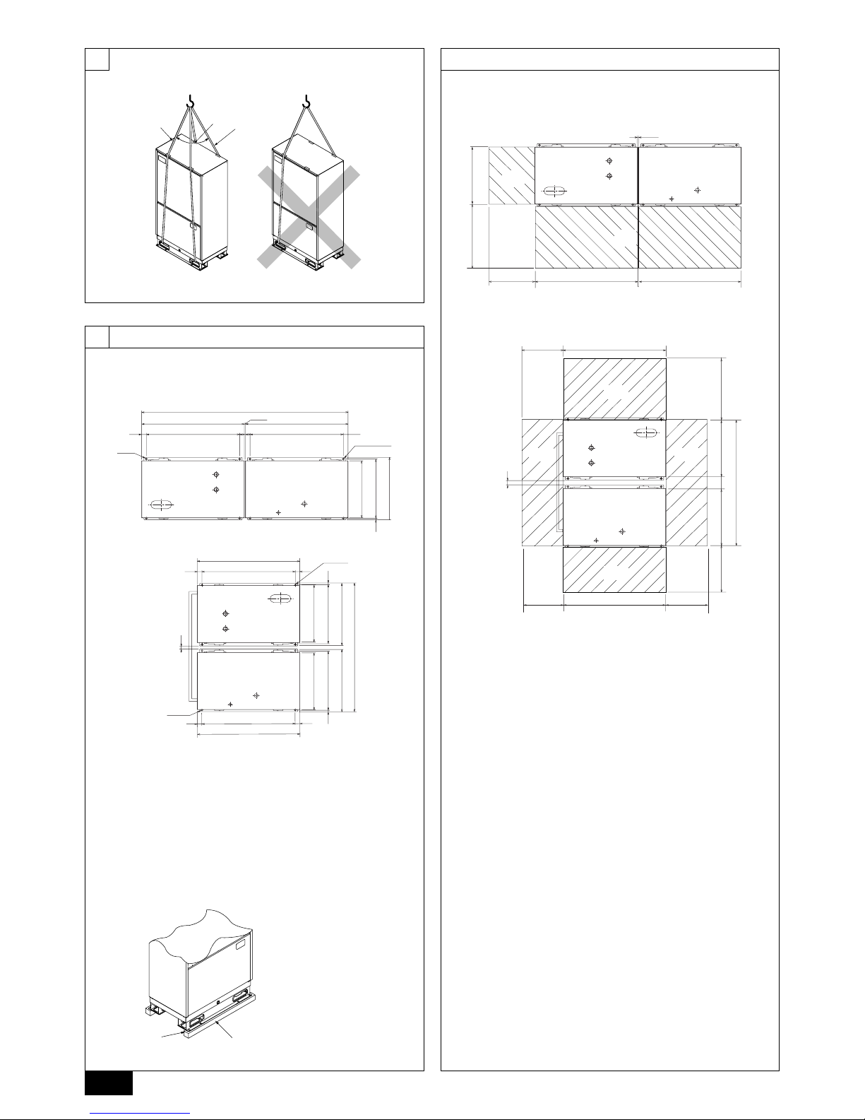
[Fig. 5.0.1]
8 m
=
>
40°
=
<
8 m
=
>
C
C
<A>
<B>
C
D
C
B
A
AB
D
1990
(10) *1
990
16
602
570
550
45900
990
45 900
990
45 900
45
990
45 900
45
16
602
570
550
16
602
570
550
(1254)
(50) *2
45 45
E
F
990400 990
550
600
(10) *1
(50) *2
400
400
990
990400
550550400 600
(1254)
BC
D
A
D
AF
D
E
E
B
C
<A>
<B>
[Fig. 6.1.1]
[Fig. 6.1.2]
[Fig. 6.2.1]
6.2
A Heat exchanger unit
B Compressor unit
C 4-ø14 (Anchoring hole)
D (Top view)
A Piping space (for side piping)
B Heat exchanger unit
C Compressor unit
D Service space (front side)
E (Top view)
F Piping space
E Anti-vibration pad etc.
F Concrete base
6.1
6
*1 Select an installation site that is level and free from vibrations so that the side
panels of the units do not rub against each other.
*2 Select an installation site that allows the fixation of the units to the floor.
<A> Side-by-side installation
<B> Back-to-back installation
*1 Select an installation site that is level and free from vibrations so that the side
panels of the units do not rub against each other.
*2 Select an installation site that allows the fixation of the units to the floor.
<A> Side-by-side installation
<B> Back-to-back installation
3
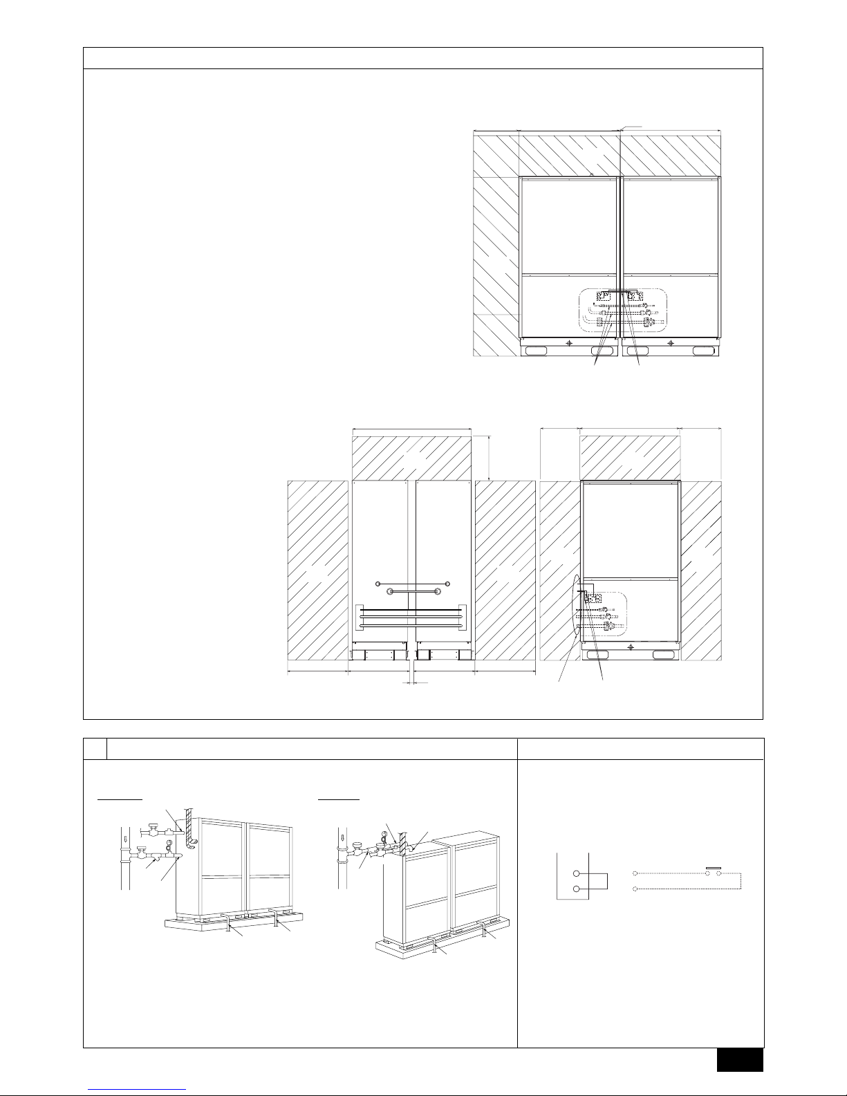
[Fig. 6.2.2]
6.2
BV5
BV3
BV4
990400 990
<A>
<B>
990400
400
BV5
BV3
BV4
400
(1254)
(50) *2
602600 600602
(10) *1
G
H
K
N O
Q
M
L
*
L
MR
I
IJ J
J
G G
P H
G Piping space (for top piping)
H Piping space (for side piping)
I Heat exchanger unit
J Compressor unit
K Field-installed pipes
Bypass pipe ø9.52 (Flare + Brazed)
High press pipe ø19.05 (Flare + Brazed)
Low press pipe ø25.4 (Flange + Brazed)
L Connecting wire between heat exchanger unit and compressor unit (External
heater adapter*)
Control signal wire (connector, on-site connection)
* If the space between the heat exchanger unit and compressor unit exceeds 1.5 m
(the length of the standard supplied external heater adapter), an optional external
heater adapter (available in 5m or10m) is necessary.
M (Front view)
N Service space (Heat exchanger unit side)
O Service space (Compressor unit side)
P Piping space
Q Pipe/wire output port
R (Side view)
E
I
J
D
H
H
G
F
C
B
A
TB8
3
A
B
4
63PW
[Fig. 7.4.1][Fig. 7.1.1]
7.1 7.4
A Water circulation pipe
B Close valve
C Close valve
D Water outlet
E Refrigerant piping
A Short-circuit wire (Connected before delivery
from manufacturer)
B Pump interlock circuit connection
7
E
D
H
H
G
F
C
B
A
I
J
F Y-type strainer
G Water inlet
H Drain pipe
I Heat exchanger unit
J Compressor unit
Side piping Top piping
<A> Side-by-side installation
<B> Sample back-to-back installation
*1 Select an installation site that is level and free from vibrations so that the side panels of
the units do not rub against each other.
*2 Select an installation site that allows the fixation of the units to the floor.
4
8
8.2
[Fig. 8.2.1]
A Heat exchanger unit
B Compressor unit
C BC controller (main)
D BC controller (sub)
E indoor unit (20 ~ 140)
F indoor unit (200, 250)
No.2
No.1
No.3 No.4
No.5 No.6
No.7
a
b
c
d
e
g
f
A
B
C
D
No.7
h
E
C
AB D
E
E
E
EE
EF
E
D
B (mm)
Î Total capacity of indoor units
~ 140
141 ~ 200
‰ Liquid line
ø9.52
ø9.52
Ï Gas line
ø15.88
ø19.05
A (mm)
Å Heat source model
P400
P500
ı High press. side
ø22.2
ø22.2
Ç Low press. side
ø28.58
ø28.58
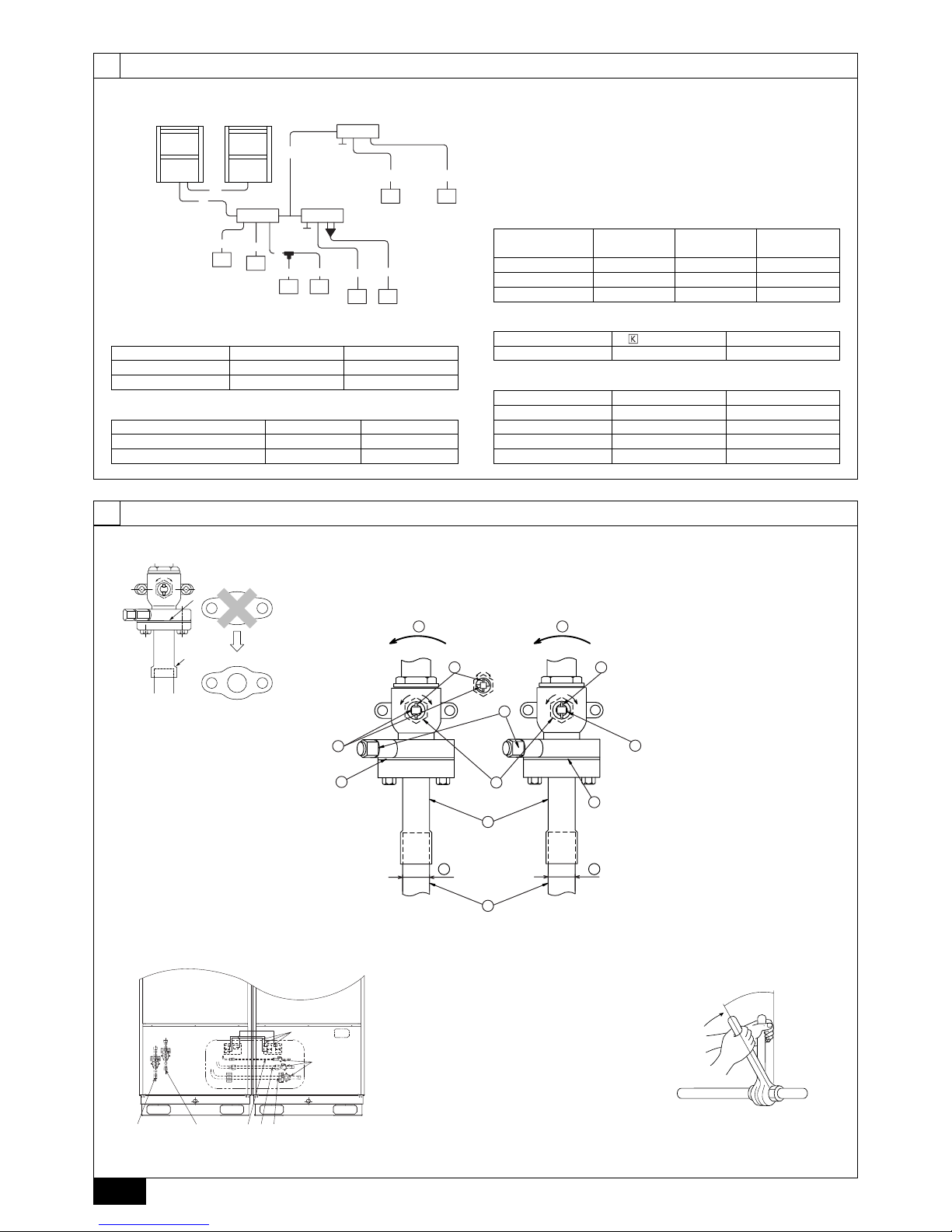
[Fig. 9.2.2]
9.2
9
[Fig. 9.2.1]
A
B
1
3
<A> [Ball valve (Low press. side/flanged type)] <B> [Ball valve (High press. side/flanged type)]
[Fig. 9.2.4]
A Close-packed packing
B Hollow packing
<C> This figure shows the valve
in the fully open state.
A Valve stem
B Stopper pin
C Packing (Accessory)
D Connecting pipe (Accessory)
E Open (Operate slowly)
F Cap
G Service port
H ø22.2 (PQRY-P400)
ø22.2 (PQRY-P500)
I ø28.58 (PQRY-P400)
ø28.58 (PQRY-P500)
J Field piping
OS
SO
SO
HI
G
F
J
D
C
C
B
E E
A
A
B
[Fig. 9.2.3]
AB
CD E
I
H
FG
a, b, c, d, e, f, g, h (mm)
˜ Model number
20,25,32,40,50
63,71,80,100,125,140
200
250
‰ Liquid line
ø6.35
ø9.52
ø9.52
ø9.52
Ï Gas line
ø12.7
ø15.88
ø19.05
ø22.2
C, D (mm)
~ 200
201 ~ 300
301 ~ 350
Ì High press.
gas pipe
ø15.88
ø19.05
ø19.05
¬ Liquid pipe
ø9.52
ø12.7
ø12.7
Ó Low press.
gas pipe
ø19.05
ø22.2
ø28.58
E
Ô High press pipe
ø19.05
Low press pipe
ø28.58
Ò Bypass pipe
ø9.52
A Heat exchanger unit
B Compressor unit
C Low press pipe (BC controller side ø28.58)
D High press pipe (BC controller side ø22.2)
E Heat exchanger unit – Compressor unit connec-
tion pipe (ø28.58 Flange + Brazed)
F Heat exchanger unit – Compressor unit connec-
tion pipe (ø19.05 Flare + Brazed)
G Heat exchanger unit – Compressor unit connec-
tion pipe (ø9.52 Flare + Brazed)
H Ball valve
I External heater adapter (3-wire)
5
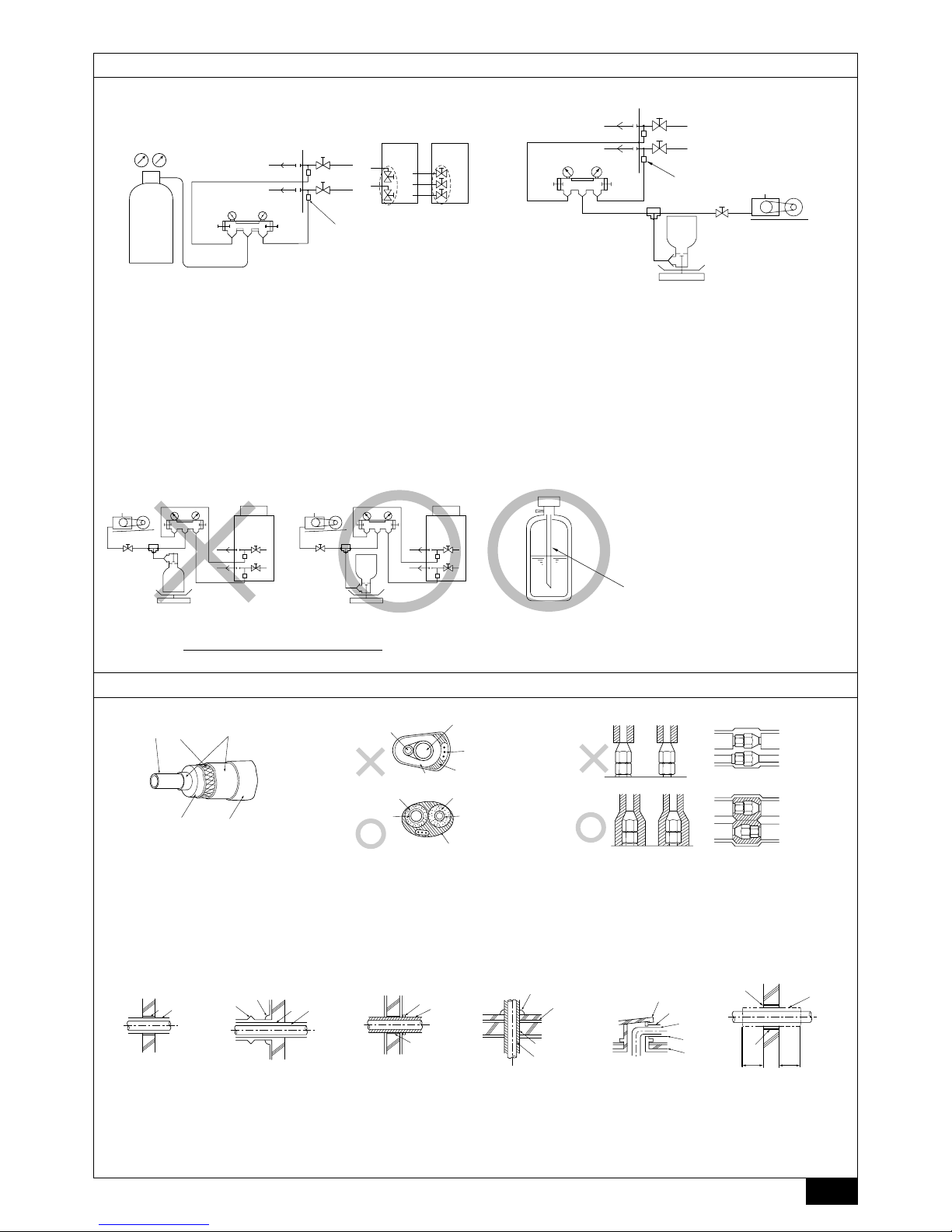
[Fig. 9.4.4]
[Fig. 9.4.3][Fig. 9.4.2]
C
A
B
D
E
[Fig. 9.4.1]
B
A
D
C
E
E
E
D
A
B
D
F
G
B
<D> Floor (waterproofing)
E
I
B
<C> Outer wall (exposed)
A B
<A> Inner wall (concealed)
A B
D
C
<B> Outer wall
F
H
D
B
G
<E> Roof pipe shaft
I
A
J
1m1m
<F> Penetrating portion on fire
limit and boundary wall
A Steel wire
B Piping
C Asphaltic oily mastic or asphalt
D Heat insulation material A
E Outer covering B
A High press. pipe
B Low press. pipe
C Electric wire
A Sleeve
B Heat insulating material
C Lagging
D Caulking material
E Band
F Waterproofing laye
D
C
C
B
B
E
F
G
KL
<A> <B>
H
I
J
A
LO
HI
LO
HI
B
A
K
J
L
H
M
C
D
EN
O
F
G
I
[Fig. 9.3.1]
[Fig. 9.3.3]
[Fig. 9.3.2]
9.3
A
A Nitrogen gas
B To indoor unit
C System analyzer
D Lo knob
E Hi knob
F Ball valve
A System analyzer
B Lo knob
C Hi knob
D Ball valve (Heat exchanger unit side)
E Low press. pipe
F High press. pipe
G Service port
H Three-way joint
I Valve
A : Syphon pipe
B In case of the cylinder having no syphon pipe.
9.4
G Low press. pipe
H High press. pipe
I Heat source unit
J Service port
K Heat exchanger unit
L Compressor unit
<A> Open
<B> Closed
J Valve
K R410A cylinder
L Scale
M Vacuum pump
N To indoor unit
O Heat source unit
D Finishing tape
E Insulator
G Sleeve with edge
H Lagging material
I Mortar or other incombustible caulking
J Incombustible heat insulation material
6
10
[Fig. 10.2.1]
10.2
ABC
L1 L2 L3 N M1M2 M1M2 S
TB3 TB7
TB1
A Power source
B Transmission line
C Earth screw
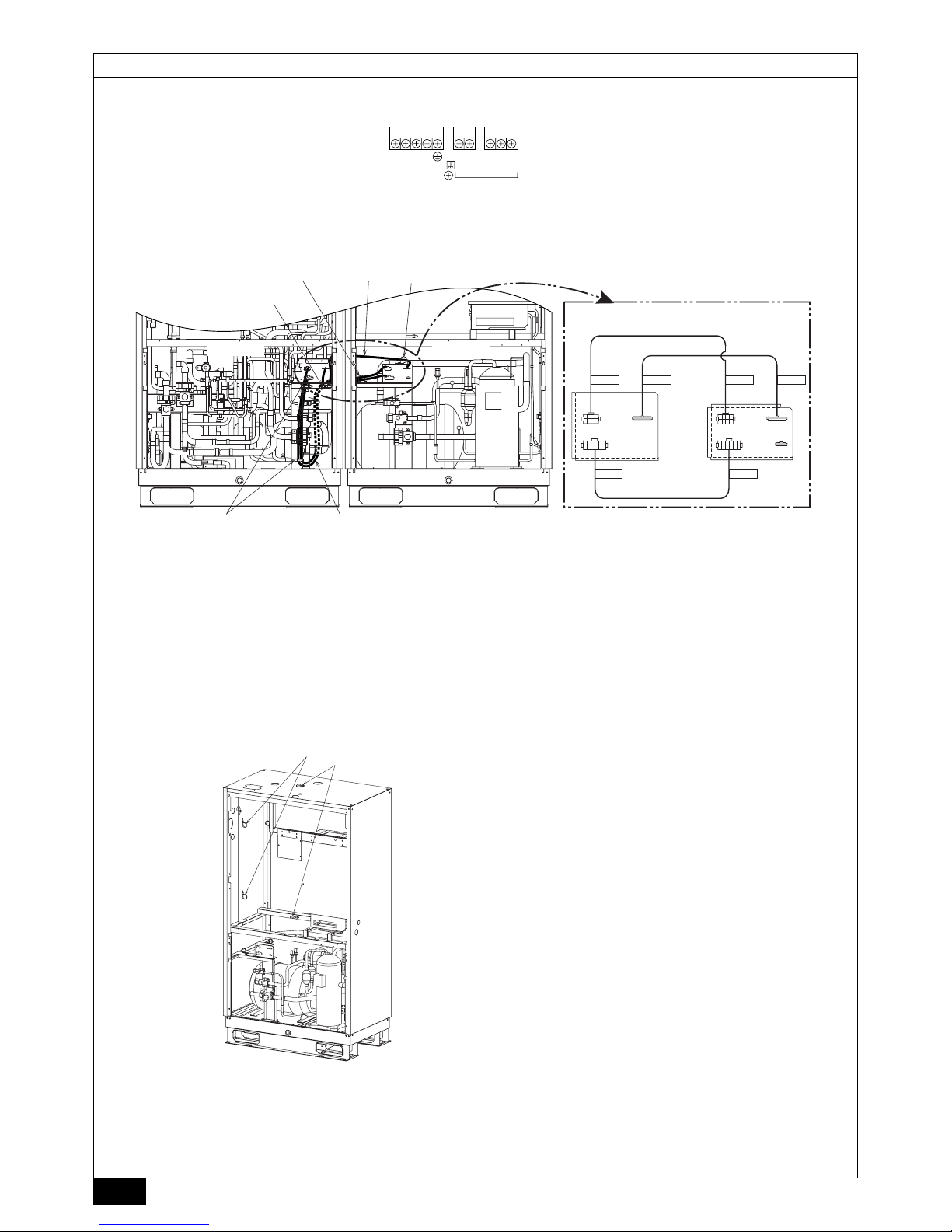
[Fig. 10.2.2]
CN103B
CN102B
CN101B
CN103A
CN102A
CN101A
CN104A
CN102B
CN101B
CN103B
CN102A
CN103A
CN101A
<A>
<B>
<D>
<G>
<H>
<I>
(*1)
<E>
<F>
<C>
D
F
C
C
D
E
A B
B
A
<A>
[Fig. 10.2.3]
A Cable clamp for power supply cable
B Cable clamp for transmission cable
<A> Compressor unit
A Heat exchanger unit
B Compressor unit
C Cable clamp (power supply line)
D Cable clamp (control line)
E Control cable
F Power supply cable
<A> Enlarged view of connector section
<B> Heat exchanger unit side
<C> Compressor unit side
<D> CN102B (For power supply line)
<E> CN103B (For control line)
<F> CN101B (For power supply line)
<G> CN102A (For power supply line)
<H> CN103A (For control line)
<I> CN101A (For power supply line)
*1 CN104A is not used for the WR2 models.
 Loading...