

Mitsubishi PQRY-P96TLMU-A, PQRY-P144TLMU-A, PQRY-P168TLMU-A, PQRY-P120TLMU-A, PQRY-P144TSLMU-A User Manual
...
PQRY-P-T(S)LMU, Y(S)LMU (April 2017 Ver2)
WR2-1
© 2017 Mitsubishi Electric US, Inc.
WR2-SERIES WATER-SOURCE UNITS
WATER-SOURCE UNITS
1. SPECIFICATIONS .....................................................................................................................................................WR2-3
1-1. PQRY-P72~336T(S)LMU-A Specications ..................................................................................................WR2-3
1-2. PQRY-P72~336Y(S)LMU-A Specications ................................................................................................WR2-15
1-3. Efciency Ratings ......................................................................................................................................WR2-27
2. EXTERNAL DIMENSIONS ......................................................................................................................................WR2-28
PQRY-P72, 96, 120TLMU-A .............................................................................................................................WR2-28
PQRY-P144, 168, 192TLMU-A .........................................................................................................................WR2-29
PQRY-P216, 240TLMU-A .................................................................................................................................WR2-30
PQRY-P144, 168, 192, 216, 240TSLMU-A .......................................................................................................WR2-31
PQRY-P288, 312, 336TSLMU-A .......................................................................................................................WR2-32
PQRY-P72, 96, 120YLMU-A .............................................................................................................................WR2-33
PQRY-P144, 168, 192YLMU-A .........................................................................................................................WR2-34
PQRY-P216, 240YLMU-A .................................................................................................................................WR2-35
PQRY-P144, 168, 192, 216, 240YSLMU-A.......................................................................................................WR2-36
PQRY-P288, 312, 336YSLMU-A .......................................................................................................................WR2-37
3. CENTER OF GRAVITY ...........................................................................................................................................WR2-38
4. ELECTRICAL WIRING DIAGRAMS ........................................................................................................................WR2-39
5. REFRIGERANT CIRCUIT DIAGRAMS ...................................................................................................................WR2-43
6. SOUND PRESSURE LEVELS ................................................................................................................................WR2-46
7. OPERATION TEMPERATURE RANGE ..................................................................................................................WR2-50
7-1. Connection with standard CITY MULTI indoor units .................................................................................. WR2-50
7-2. Connection with PWFY-P36NMU-E-BU (Booster unit) .............................................................................. WR2-51
7-3. Connection with PWFY-P36/72NMU-E2-AU (HEX unit) ............................................................................ WR2-51
8. CAPACITY TABLES ................................................................................................................................................WR2-52
8-1. Correction by Temperature in Fahrenheit ..................................................................................................WR2-52
8-2. Correction by Temperature in Celsius .......................................................................................................WR2-68
8-3. Water temperature correction factors (Geothermal) ..................................................................................WR2-84
8-4. Water volume correction factors (Geothermal) ..........................................................................................WR2-86
8-5. Indoor temperature correction factors (Geothermal) .................................................................................WR2-91
8-6. Glycol correction factors ............................................................................................................................WR2-94
8-7. Glycol freeze protection % ........................................................................................................................WR2-98
8-8. Correction by Total Indoor .........................................................................................................................WR2-99
8-9. Correction by Refrigerant Piping Length .................................................................................................WR2-105
9. OPTIONAL PARTS ................................................................................................................................................WR2-109
9-1. Branch Joint .............................................................................................................................................WR2-109
9-2. Headers ................................................................................................................................................... WR2-110
9-3. Water-source Unit Twinning Kit ............................................................................................................... WR2-111
9-4. Joint Adapter Kit ......................................................................................................................................WR2-112

WR2-2
PQRY-P-T(S)LMU, Y(S)LMU (April 2017 Ver2)
© 2017 Mitsubishi Electric US, Inc.
10. ELECTRICAL WORK ..........................................................................................................................................WR2-113
10-1. General Cautions ................................................................................................................................... WR2-113
10-2. Power Supply for Indoor Unit and Outdoor Unit .................................................................................... WR2-114
10-3. Power Cable Specications ................................................................................................................... WR2-118
10-4. Power Supply Examples ........................................................................................................................ WR2-119
11. M-NET CONTROL ...............................................................................................................................................WR2-121
11-1. Transmission Cable Length Limitation ...................................................................................................WR2-121
11-2. Transmission Cable Specications ........................................................................................................WR2-122
11-3. System Conguration Restrictions .........................................................................................................WR2-123
11-4. Address Setting ......................................................................................................................................WR2-126
12. PIPING DESIGN .................................................................................................................................................WR2-139
12-1. R410A Piping Material ...........................................................................................................................WR2-139
12-2. Piping Design ........................................................................................................................................WR2-139
12-3. Refrigerant Charging Calculation ..........................................................................................................WR2-143
13. INSTALLATION ...................................................................................................................................................WR2-145
13-1. PQRY-P-T(S)LMU/Y(S)LMU’s Installation .............................................................................................WR2-145
13-2. Installation Space ..................................................................................................................................WR2-145
13-3. Piping Direction .....................................................................................................................................WR2-146
14. INSTALLATION INFORMATION .........................................................................................................................WR2-147
14-1. General Precautions ..............................................................................................................................WR2-147
14-2. Precautions for Indoor unit ....................................................................................................................WR2-148
14-3. Precautions for Outdoor unit/Heat source unit ......................................................................................WR2-149
14-4. Precautions for Control-related items ....................................................................................................WR2-150
15. CAUTION FOR REFRIGERANT LEAKAGE .......................................................................................................WR2-151
15-1. Refrigerant property ...............................................................................................................................WR2-151
15-2. Conrm the Critical concentration and take countermeasure................................................................WR2-151
WR2-
PQRY-P-T(S)LMU, Y(S)LMU (April 2017 Ver2)
WR2-3
© 2017 Mitsubishi Electric US, Inc.
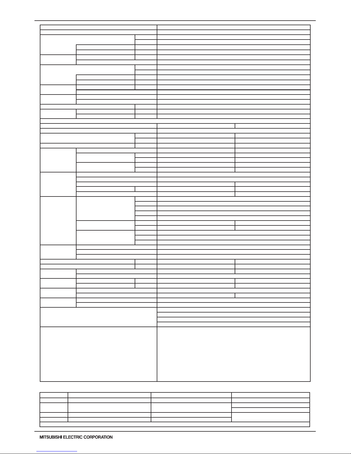
Note: *1 Nominal cooling conditions (subject to JIS B8615-1) *2 Nominal heating conditions (subject to JIS B8615-1) Unit converter
Indoor: 81degF D.B./ 66degF W.B. (27degC D.B./ 19degC W.B.) 68degF D.B. (20degC D.B.) BTU/h =kW x 3,412
Water Temp.: 86degF (30degC) 68degF (20degC)
cfm =m3/min x 35.31
lb =kg / 0.4536
Pipe length: 24-9/16ft.(7.5m) 25ft.(7.6m)
* Above specication data is subject to rounding
variation.
Level difference: 0ft.(0m) 0ft.(0m)
* Due to continuing improvement, above specications may be subject to change without notice.
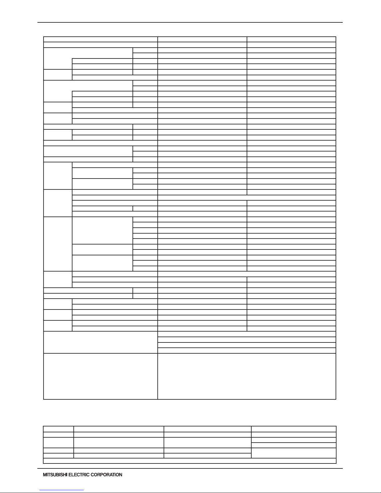
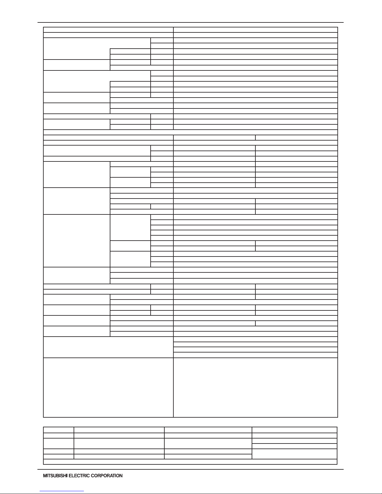
1. SPECIFICATIONS
1-1. PQRY-P72~336T(S)LMU-A Specications
Model PQRY-P72TLMU-A PQRY-P96TLMU-A
Power source 3-phase 3-wire 208 / 230 ±10% 60Hz 3-phase 3-wire 208 / 230 ±10% 60Hz
Cooling capacity (Nominal) *1 (208/230V)
Btu/h 72,000 96,000
kW 21.1 28.1
Power input kW 3.23 4.65
Current input A 9.9-9.0 14.3-12.9
Temp. range of
cooling
Indoor W.B. 59~75° F (15~24° C) 59~75° F (15~24° C)
Circulating water *3 50~113° F (10~45° C) 50~113° F (10~45° C)
Heating capacity (Nominal) *2 (208/230V)
Btu/h 80,000 108,000
kW 23.4 31.7
Power input kW 3.63 5.05
Current input A 11.1-10.1 15.5-14.0
Temp. range of
heating
Indoor D.B. 59~81° F (15~27° C) 59~81° F (15~27° C)
Circulating water *3 50~113° F (10~45° C) 50~113° F (10~45° C)
Indoor unit
connectable
Total capacity 50~150% of heat source unit capacity 50~150% of heat source unit capacity
Model / Quantity P06~P96/1~18 P06~P96/1~24
Sound pressure level (measured in anechoic room) dB <A> 46 48
Refrigerant
piping diameter
High pressure in.(mm) 5/8 (15.88) Brazed 3/4 (19.05) Brazed
Low pressure in.(mm) 3/4 (19.05) Brazed 7/8 (22.2) Brazed
External nish Galvanized steel sheets Galvanized steel sheets
External dimension HxWxD
in. 43-5/16 x 34-11/16 x 21-11/16 43-5/16 x 34-11/16 x 21-11/16
mm 1,100 x 880 x 550 1,100 x 880 x 550
Net weight lbs(kg) 380 (172) 380 (172)
Heat
exchanger
Type Plate Plate
Water volume in plate
G 1.32 1.32
I 5 5
Water pressure Max.
psi 290 290
MPa 2 2
Compressor
Type Inverter scroll hermetic compressor Inverter scroll hermetic compressor
Manufacturer AC&R Works, MITSUBISHI ELECTRIC CORPORATION
Starting method Inverter Inverter
Motor output kW 4.3 6.0
Lubricant MEL32 MEL32
Circulating
water *3
Water ow rate
G/h 1,522 1,522
G/min(gpm) 25.4 25.4
m3 / h 5.76 5.76
L/min 96 96
cfm 3.4 3.4
Pressure drop
psi 3.48 3.48
kPa 24 24
Operating volume range
G/h 793 ~ 1,902 793 ~ 1,902
G/min(gpm) 13.2 ~ 31.7 13.2 ~ 31.7
m3 / h 3.0 ~ 7.2 3.0 ~ 7.2
Protection
devices
High pressure protection High pressure sensor, High pressure switch at 4.15 MPa (601 psi)
Inverter circuit(comp) Over-heat protection, Over-current protection Over-heat protection, Over-current protection
Compressor Over-heat protection Over-heat protection
Minimum Circuit Ampacity(MCA) A 13 / 12 19 / 17
Maximum Overcurrent Protection(MOP) A 20 / 20 30 / 25
Refrigerant
Type x original charge R410A x (11 lbs + 1 oz) (5.0 kg) R410A x (11 lbs + 1 oz) (5.0 kg)
Control Indoor LEV and BC controller Indoor LEV and BC controller
Drawing
External KJ94T127 KJ94T127
Wiring KE94C966 KE94C966
Standard
attachment
Document Installation Manual Installation Manual
Accessory Details refer to External Drw Details refer to External Drw
Optional parts
Joint: CMY-Y102SS-G2, CMY-Y102LS-G2, CMY-R160-J1
BC controller: CMB-P104, 105, 106, 108, 1010, 1013, 1016NU-G1
Main BC controller: CMB-P108, 1010, 1013, 1016NU-GA1, 108, 1010, 1016NU-HA1
Sub BC controller: CMB-P104, 108NU-GB1, CMB-P1016NU-HB1
Remarks
Details on foundation work, duct work, insulation work, electrical wiring, power source switch, and other
items shall be referred to the Installation Manual.
The ambient temperature of the Heat Source Unit needs to be kept below 104°F DB(40° C DB).
The ambient relative humidity of the Heat Source Unit needs to be kept below 80%.
The Heat Source Unit should not be installed at outdoor.
Mount a strainer (more than 50 meshes) at the water inlet piping of the unit.
A eld provided ow switch is required for minimum ow protection on each module, eld installed and
wired to TB8 (terminal 3-4).
*3 If using Circulating water temperatures that are between 23 and 50° F, Dip switch 3-9 must be turned
on and glycol must be used in the water loop to prevent freezing down to 5° F.
WR2-4
PQRY-P-T(S)LMU, Y(S)LMU (April 2017 Ver2)
© 2017 Mitsubishi Electric US, Inc.
1. SPECIFICATIONS
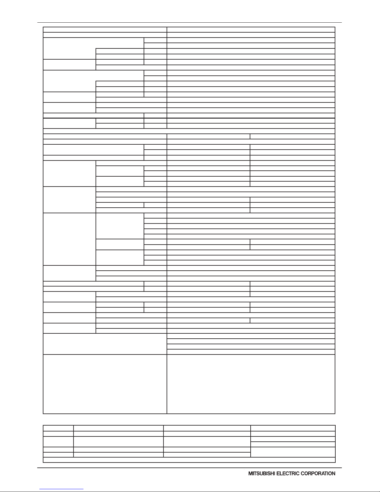
Note: *1 Nominal cooling conditions (subject to JIS B8615-1) *2 Nominal heating conditions (subject to JIS B8615-1) Unit converter
Indoor: 81degF D.B./ 66degF W.B. (27degC D.B./ 19degC W.B.) 68degF D.B. (20degC D.B.) BTU/h =kW x 3,412
Water Temp.: 86degF (30degC) 68degF (20degC)
cfm =m3/min x 35.31
lb =kg / 0.4536
Pipe length: 24-9/16ft.(7.5m) 25ft.(7.6m)
* Above specication data is subject to rounding
variation.
Level difference: 0ft.(0m) 0ft.(0m)
* Due to continuing improvement, above specications may be subject to change without notice.
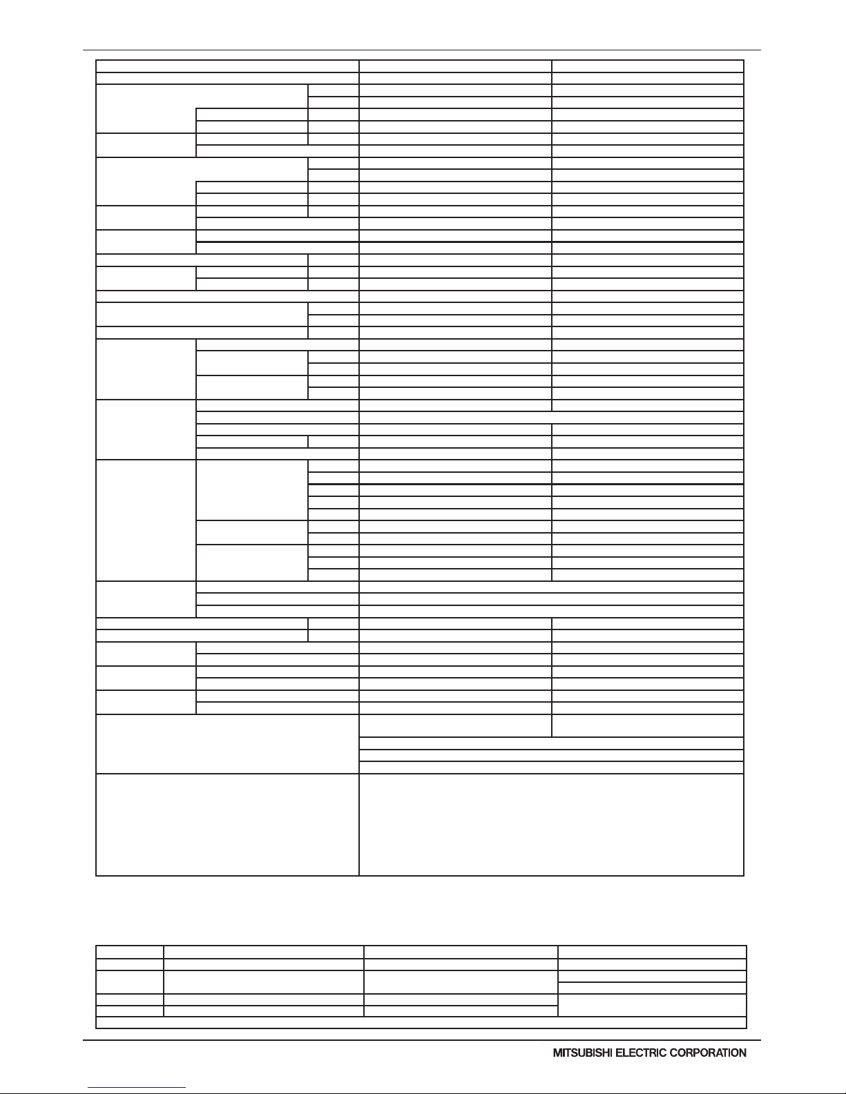
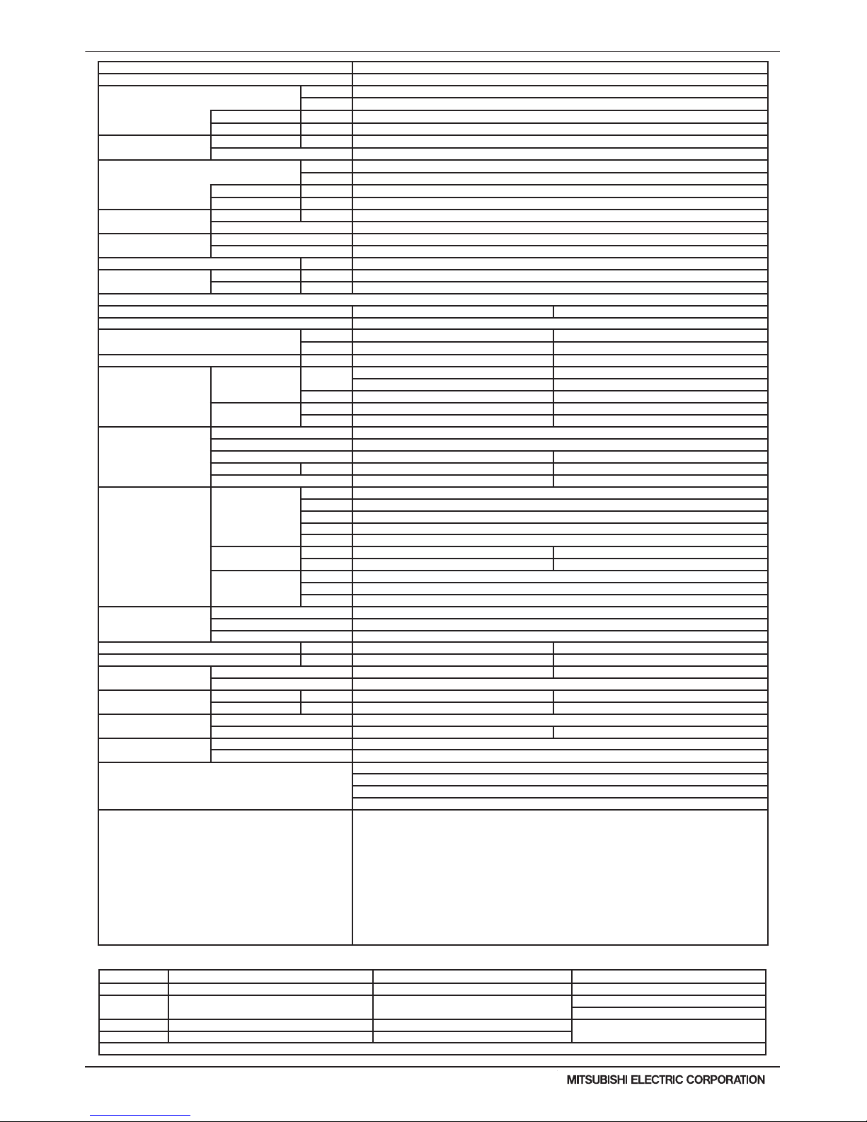
Model PQRY-P120TLMU-A PQRY-P144TLMU-A
Power source 3-phase 3-wire 208 / 230 ±10% 60Hz 3-phase 3-wire 208 / 230 ±10% 60Hz
Cooling capacity (Nominal) *1 (208/230V)
Btu/h 120,000 144,000
kW 35.2 42.2
Power input kW 7.24 8.78
Current input A 22.3 / 20.1 27.0 / 24.4
Temp. range of
cooling
Indoor W.B. 59~75° F (15~24° C) 59~75° F (15~24° C)
Circulating water *3 50~113° F (10~45° C) 50~113° F (10~45° C)
Heating capacity (Nominal) *2 (208/230V)
Btu/h 135,000 160,000
kW 39.6 46.9
Power input kW 6.83 8.11
Current input A 21.0 / 19.0 25.0 / 22.6
Temp. range of
heating
Indoor D.B. 59~81° F (15~27° C) 59~81° F (15~27° C)
Circulating water *3 50~113° F (10~45° C) 50~113° F (10~45° C)
Indoor unit connectable
Total capacity 50~150% of heat source unit capacity 50~150% of heat source unit capacity
Model / Quantity P06~P96/1~30 P06~P96/1~36
Sound pressure level (measured in anechoic room) dB <A> 54 54
Refrigerant piping
diameter
High pressure in.(mm) 3/4 (19.05) Brazed 7/8 (22.2) Brazed
Low pressure in.(mm) 7/8 (22.2) Brazed 1-1/8 (28.58) Brazed
External nish Galvanized steel sheets Galvanized steel sheets
External dimension HxWxD
in. 43-5/16 x 34-11/16 x 21-11/16 43-5/16 x 34-11/16 x 21-11/16
mm 1,100 x 880 x 550 1,100 x 880 x 550
Net weight lbs(kg) 380 (172) 380 (172)
Heat exchanger
Type Plate Plate
Water volume in plate
G 1.32 1.32
I 5 5
Water pressure Max.
psi 290 290
MPa 2 2
Compressor
Type Inverter scroll hermetic compressor Inverter scroll hermetic compressor
Manufacturer AC&R Works, MITSUBISHI ELECTRIC CORPORATION
Starting method Inverter Inverter
Motor output kW 7.7 9.5
Lubricant MEL32
Circulating water *3
Water ow rate
G/h 1,522 1,902
G/min(gpm) 25.4 31.7
m3 / h 5.76 7.2
L/min 96 120
cfm 3.4 4.2
Pressure drop
psi 3.48 6.38
kPa 24 44
Operating volume range
range
G/h 793 ~ 1,902 1,189 ~ 3,054
G/min(gpm) 13.2 ~ 31.7 19.8 ~ 50.9
m3 / h 3.0 ~ 7.2 4.5 ~ 11.6
Protection devices
High pressure protection High pressure sensor, High pressure switch at 4.15 MPa (601 psi)
Inverter circuit(comp) Over-heat protection, Over-current protection
Compressor Over-heat protection
Minimum Circuit Ampacity(MCA) A 29 / 26 35 / 32
Maximum Overcurrent Protection(MOP) A 50 / 45 60 / 50
Refrigerant
Type x original charge R410A x 11 lbs + 1 oz (5.0 kg) R410A x 11 lbs + 1 oz (5.0 kg)
Control Indoor LEV and BC controller Indoor LEV and BC controller
Drawing
External KJ94T127 KJ94T127
Wiring KE94C966 KE94C966
Standard attachment
Document Installation Manual Installation Manual
Accessory Details refer to External Drw Details refer to External Drw
Optional parts
Joint: CMY-Y102SS-G2, CMY-Y102LS-G2,
CMY-R160-J1
Joint: CMY-Y102SS-G2, CMY-Y102LS-G2,
CMY-Y202S-G2, CMY-R160-J1
BC controller: CMB-P104, 105, 106, 108, 1010, 1013, 1016NU-G1
Main BC controller: CMB-P108, 1010, 1013, 1016NU-GA1, 108, 1010, 1016NU-HA1
Sub BC controller: CMB-P104, 108NU-GB1, CMB-P1016NU-HB1
Remarks
Details on foundation work, duct work, insulation work, electrical wiring, power source switch, and
other items shall be referred to the Installation Manual.
The ambient temperature of the Heat Source Unit needs to be kept below 104°F DB(40° C DB).
The ambient relative humidity of the Heat Source Unit needs to be kept below 80%.
The Heat Source Unit should not be installed at outdoor.
Mount a strainer (more than 50 meshes) at the water inlet piping of the unit.
A eld provided ow switch is required for minimum ow protection on each module, eld installed and
wired to TB8 (terminal 3-4).
*3 If using Circulating water temperatures that are between 23 and 50° F, Dip switch 3-9 must be
turned on and glycol must be used in the water loop to prevent freezing down to 5° F.
PQRY-P-T(S)LMU, Y(S)LMU (April 2017 Ver2)
WR2-5
© 2017 Mitsubishi Electric US, Inc.
1. SPECIFICATIONS
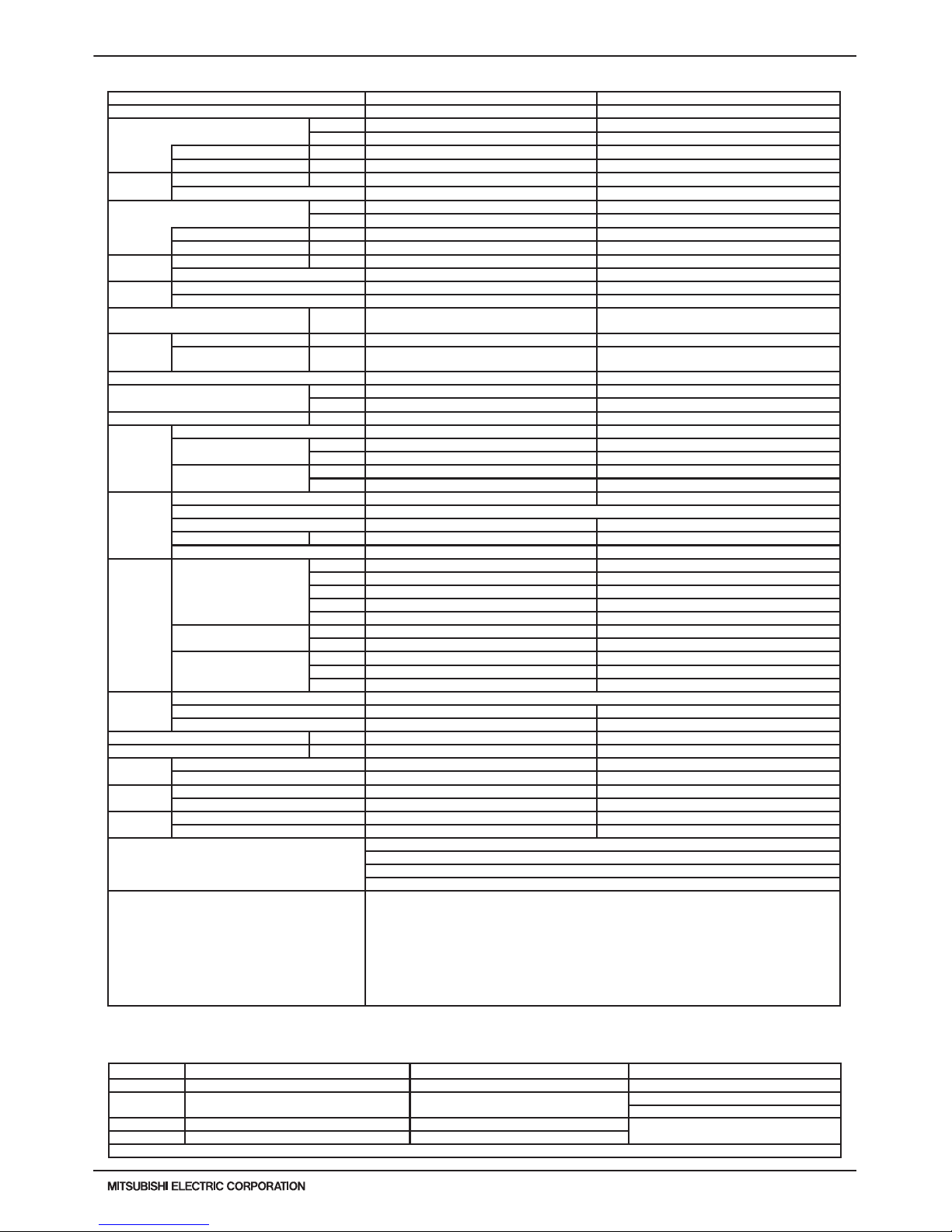
Note: *1 Nominal cooling conditions (subject to JIS B8615-1) *2 Nominal heating conditions (subject to JIS B8615-1) Unit converter
Indoor: 81degF D.B./ 66degF W.B. (27degC D.B./ 19degC W.B.) 68degF D.B. (20degC D.B.) BTU/h =kW x 3,412
Water Temp.: 86degF (30degC) 68degF (20degC)
cfm =m3/min x 35.31
lb =kg / 0.4536
Pipe length: 24-9/16ft.(7.5m) 25ft.(7.6m)
* Above specication data is subject to rounding
variation.
Level difference: 0ft.(0m) 0ft.(0m)
* Due to continuing improvement, above specications may be subject to change without notice.
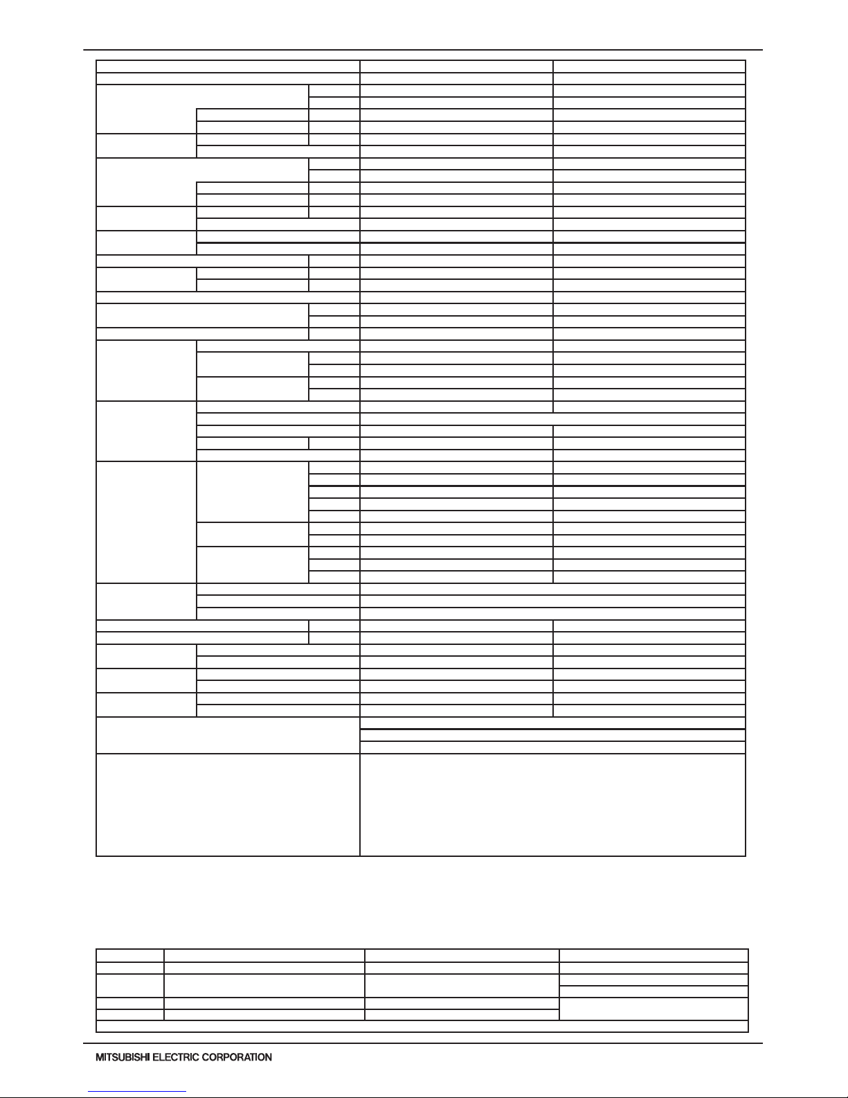
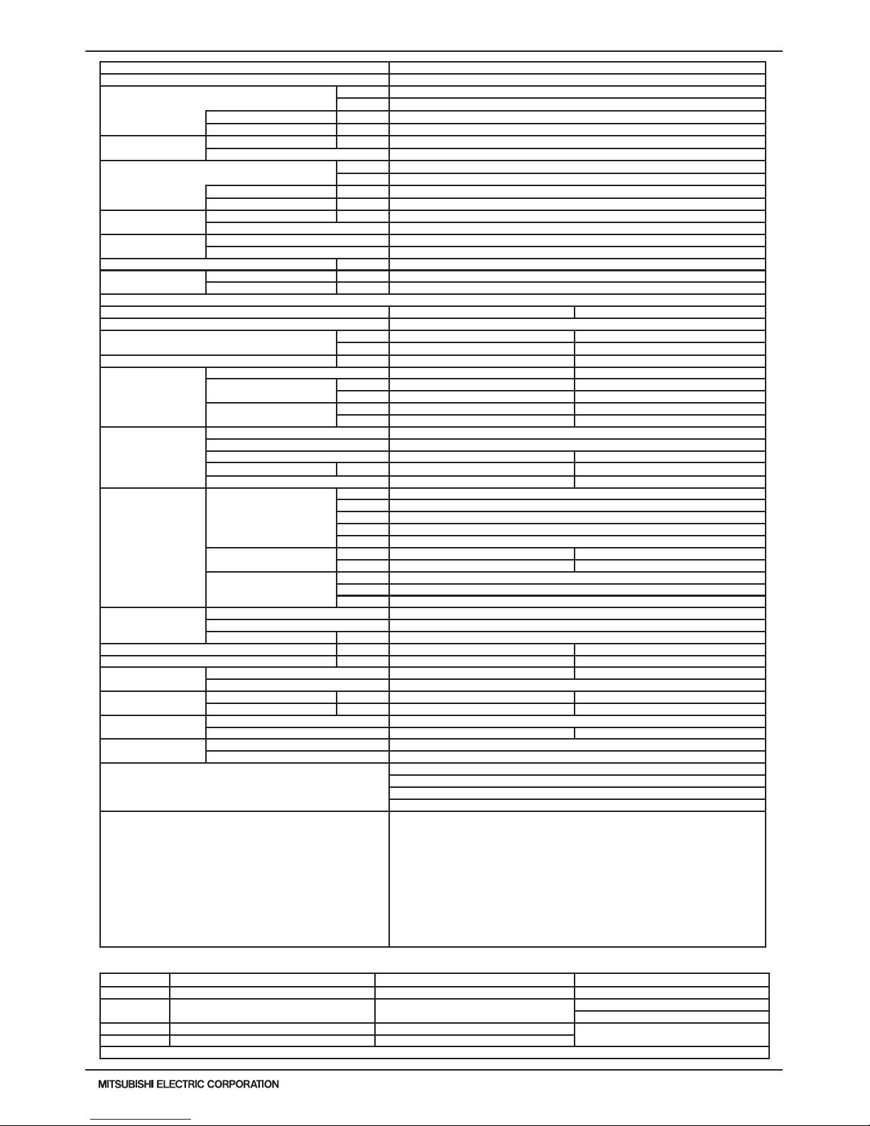
Model PQRY-P168TLMU-A PQRY-P192TLMU-A
Power source 3-phase 3-wire 208 / 230 ±10% 60Hz 3-phase 3-wire 208 / 230 ±10% 60Hz
Cooling capacity (Nominal) *1 (208/230V)
Btu/h 168,000 192,000
kW 49.2 56.3
Power input kW 12.05 15.05
Current input A 37.1 / 33.6 46.4 / 41.9
Temp. range of
cooling
Indoor W.B. 59~75° F (15~24° C) 59~75° F (15~24° C)
Circulating water *3 50~113° F (10~45° C) 50~113° F (10~45° C)
Heating capacity (Nominal) *2 (208/230V)
Btu/h 188,000 215,000
kW 55.1 63
Power input kW 9.86 11.9
Current input A 30.4 / 27.5 36.7 / 33.1
Temp. range of
heating
Indoor D.B. 59~81° F (15~27° C) 59~81° F (15~27° C)
Circulating water *3 50~113° F (10~45° C) 50~113° F (10~45° C)
Indoor unit connectable
Total capacity 50~150% of heat source unit capacity 50~150% of heat source unit capacity
Model / Quantity P06~P96/1~42 P06~P96/1~48
Sound pressure level (measured in anechoic room) dB <A> 56 58
Refrigerant piping
diameter
High pressure in.(mm) 7/8 (22.2) Brazed 7/8 (22.2) Brazed
Low pressure in.(mm) 1-1/8 (28.58) Brazed 1-1/8 (28.58) Brazed
External nish Galvanized steel sheets Galvanized steel sheets
External dimension HxWxD
in. 57-1/8 x 34-11/16 x 21-11/16 57-1/8 x 34-11/16 x 21-11/16
mm 1,450 x 880 x 550 1,450 x 880 x 550
Net weight lbs(kg) 479 (217) 479 (217)
Heat exchanger
Type Plate Plate
Water volume in plate
G 1.32 1.32
I 5 5
Water pressure Max.
psi 290 290
MPa 2 2
Compressor
Type Inverter scroll hermetic compressor Inverter scroll hermetic compressor
Manufacturer AC&R Works, MITSUBISHI ELECTRIC CORPORATION
Starting method Inverter Inverter
Motor output kW 11.0 12.4
Lubricant MEL32 MEL32
Circulating water *3
Water ow rate
G/h 1,902 1,902
G/min(gpm) 31.7 31.7
m3 / h 7.2 7.2
L/min 120 120
cfm 4.2 4.2
Pressure drop
psi 6.38 6.38
kPa 44 44
Operating volume range
range
G/h 1,189 ~ 3,054 1,189 ~ 3,054
G/min(gpm) 19.8 ~ 50.9 19.8 ~ 50.9
m3 / h 4.5 ~ 11.6 4.5 ~ 11.6
Protection devices
High pressure protection High pressure sensor, High pressure switch at 4.15 MPa (601 psi)
Inverter circuit(comp) Over-heat protection, Over-current protection
Compressor Over-heat protection
Minimum Circuit Ampacity(MCA) A 44 / 39 54 / 49
Maximum Overcurrent Protection(MOP) A 70 / 70 90 / 80
Refrigerant
Type x original charge R410A x 13 lbs + 4 oz (6.0 kg) R410A x 13 lbs + 4 oz (6.0 kg)
Control Indoor LEV and BC controller Indoor LEV and BC controller
Drawing
External KJ94T128 KJ94T128
Wiring KE94C968 KE94C968
Standard attachment
Document Installation Manual Installation Manual
Accessory Details refer to External Drw Details refer to External Drw
Optional parts
Joint: CMY-Y102SS-G2, CMY-Y102LS-G2, CMY-Y202S-G2, CMY-Y302S-G2, CMY-R160-J1
Main BC controller: CMB-P108, 1010, 1013, 1016NU-GA1, 108, 1010, 1016NU-HA1
Sub BC controller: CMB-P104, 108NU-GB1, CMB-P1016NU-HB1
Remarks
Details on foundation work, duct work, insulation work, electrical wiring, power source switch, and
other items shall be referred to the Installation Manual.
The ambient temperature of the Heat Source Unit needs to be kept below 104°F DB(40° C DB).
The ambient relative humidity of the Heat Source Unit needs to be kept below 80%.
The Heat Source Unit should not be installed at outdoor.
Mount a strainer (more than 50 meshes) at the water inlet piping of the unit.
A eld provided ow switch is required for minimum ow protection on each module, eld installed and
wired to TB8 (terminal 3-4).
*3 If using Circulating water temperatures that are between 23 and 50° F, Dip switch 3-9 must be
turned on and glycol must be used in the water loop to prevent freezing down to 5° F.
WR2-6
PQRY-P-T(S)LMU, Y(S)LMU (April 2017 Ver2)
© 2017 Mitsubishi Electric US, Inc.
1. SPECIFICATIONS
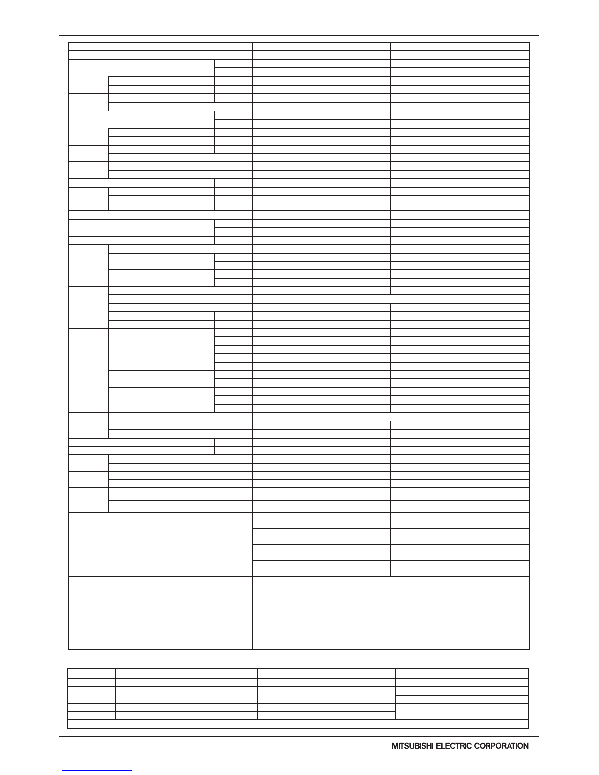
Note: *1 Nominal cooling conditions (subject to JIS B8615-1) *2 Nominal heating conditions (subject to JIS B8615-1) Unit converter
Indoor: 81degF D.B./ 66degF W.B. (27degC D.B./ 19degC W.B.) 68degF D.B. (20degC D.B.) BTU/h =kW x 3,412
Water Temp.: 86degF (30degC) 68degF (20degC)
cfm =m3/min x 35.31
lb =kg / 0.4536
Pipe length: 24-9/16ft.(7.5m) 25ft.(7.6m)
* Above specication data is subject to rounding
variation.
Level difference: 0ft.(0m) 0ft.(0m)
* Due to continuing improvement, above specications may be subject to change without notice.
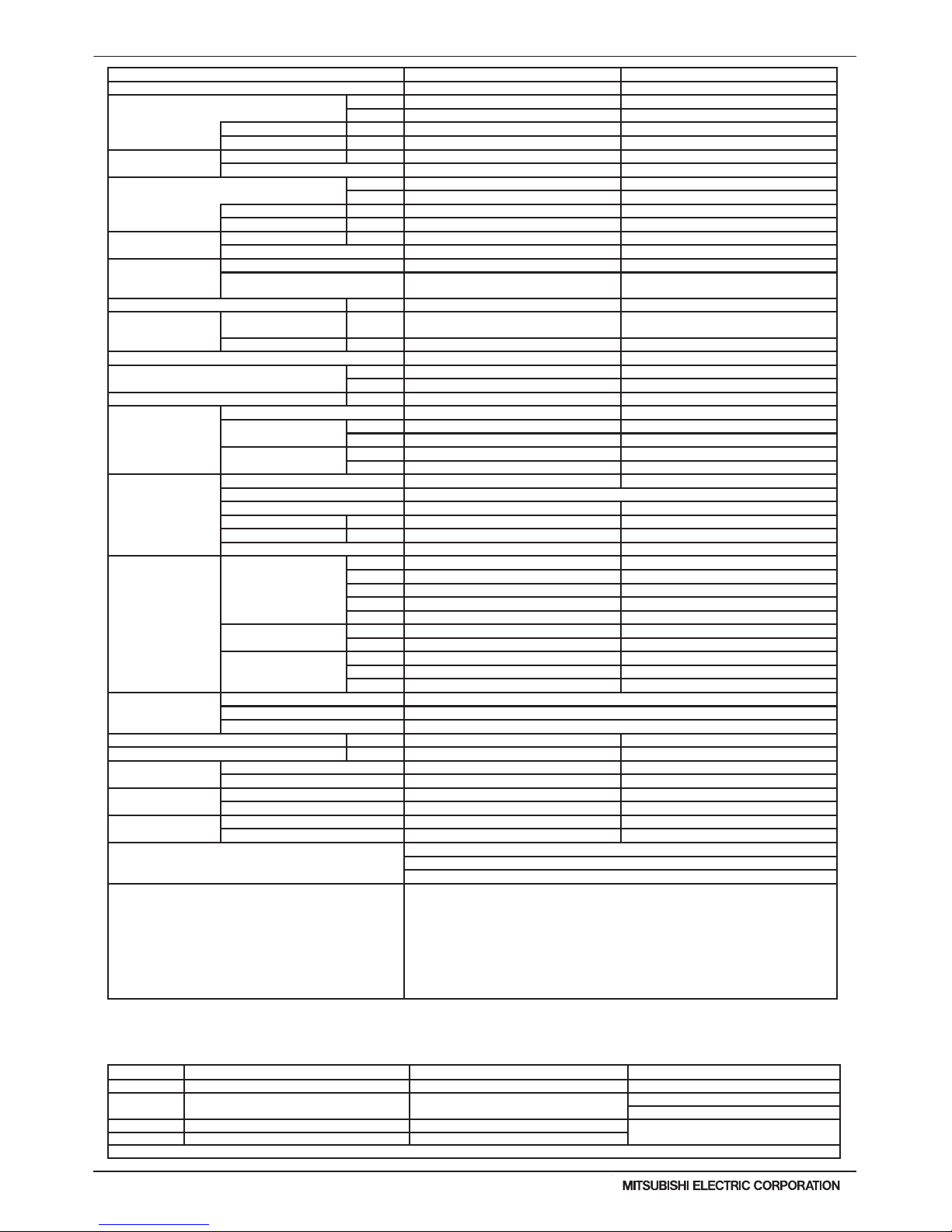
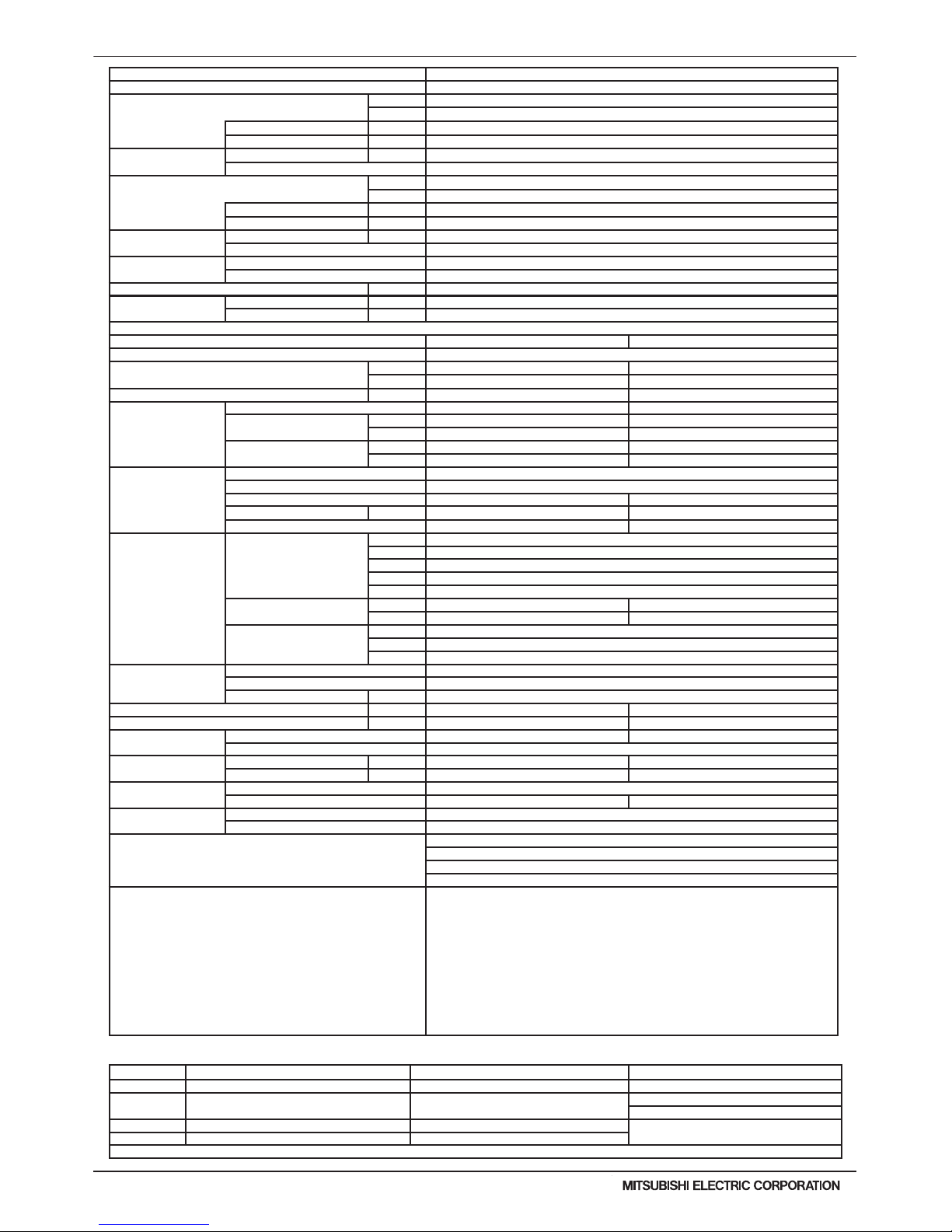
Model PQRY-P216TLMU-A PQRY-P240TLMU-A
Power source 3-phase 3-wire 208 / 230 ±10% 60Hz 3-phase 3-wire 208 / 230 ±10% 60Hz
Cooling capacity (Nominal) *1 (208/230V)
Btu/h 216,000 240,000
kW 63.3 70.3
Power input kW 19.23 21.14
Current input A 59.3 / 53.6 65.1 / 58.9
Temp. range of
cooling
Indoor W.B. 59~75° F (15~24° C) 59~75° F (15~24° C)
Circulating water *3 50~113° F (10~45° C) 50~113° F (10~45° C)
Heating capacity (Nominal) *2 (208/230V)
Btu/h 243,000 270,000
kW 71.2 79.1
Power input kW 13.04 15.12
Current input A 40.2 / 36.3 46.6 / 42.1
Temp. range of
heating
Indoor D.B. 59~81° F (15~27° C) 59~81° F (15~27° C)
Circulating water *3 50~113° F (10~45° C) 50~113° F (10~45° C)
Indoor unit connectable
Total capacity 50~150% of heat source unit capacity 50~150% of heat source unit capacity
Model / Quantity
P06~P96/2~50
(Connectable branch pipe number is max. 48.)
P06~P96/2~50
(Connectable branch pipe number is max. 48.)
Sound pressure level (measured in anechoic room) dB <A> 58 58
Refrigerant piping
diameter
High pressure in.(mm)
7/8 (22.2) Brazed (1-1/8 (28.58)
Brazed for the part that exceeds 65 m)
7/8 (22.2) Brazed (1-1/8 (28.58)
Brazed for the part that exceeds 65 m)
Low pressure in.(mm) 1-1/8 (28.58) Brazed 1-3/8 (34.93) Brazed
External nish Galvanized steel sheets Galvanized steel sheets
External dimension HxWxD
in. 57-1/8 x 34-11/16 x 21-11/16 57-1/8 x 34-11/16 x 21-11/16
mm 1,450 x 880 x 550 1,450 x 880 x 550
Net weight lbs(kg) 556 (252) 556 (252)
Heat exchanger
Type Plate Plate
Water volume in plate
G 2.64 2.64
I 10 10
Water pressure Max.
psi 290 290
MPa 2 2
Compressor
Type Inverter scroll hermetic compressor Inverter scroll hermetic compressor
Manufacturer AC&R Works, MITSUBISHI ELECTRIC CORPORATION
Starting method Inverter Inverter
Motor output kW 14.5 16.1
Case heater kW 0.045 (240 V) 0.045 (240 V)
Lubricant MEL32 MEL32
Circulating water *3
Water ow rate
G/h 3,044 3,044
G/min(gpm) 50.7 50.7
m3 / h 11.52 11.52
L/min 192 192
cfm 6.8 6.8
Pressure drop
psi 6.53 6.53
kPa 45 45
Operating volume range
range
G/h 1,585 ~ 3,804 1,585 ~ 3,804
G/min(gpm) 26.4 ~ 63.4 26.4 ~ 63.4
m3 / h 6.0 ~ 14.4 6.0 ~ 14.4
Protection devices
High pressure protection High pressure sensor, High pressure switch at 4.15 MPa (601 psi)
Inverter circuit(comp) Over-heat protection, Over-current protection
Compressor Over-heat protection
Minimum Circuit Ampacity(MCA) A 69 / 63 79 / 71
Maximum Overcurrent Protection(MOP) A 110 / 110 125 / 125
Refrigerant
Type x original charge R410A x 25 lbs + 13 oz (11.7 kg) R410A x 25 lbs + 13 oz (11.7 kg)
Control Indoor LEV and BC controller Indoor LEV and BC controller
Drawing
External KJ94T172 KJ94T172
Wiring KE94G037 KE94G037
Standard attachment
Document Installation Manual Installation Manual
Accessory Details refer to External Drw Details refer to External Drw
Optional parts
Joint: CMY-Y102SS-G2, CMY-Y102LS-G2, CMY-Y202S-G2, CMY-Y302S-G2, CMY-R160-J1
Main BC controller: CMB-P108, 1010, 1013, 1016NU-GA1, 108, 1010, 1016NU-HA1
Sub BC controller: CMB-P104, 108NU-GB1, CMB-P1016NU-HB1
Remarks
Details on foundation work, duct work, insulation work, electrical wiring, power source switch, and
other items shall be referred to the Installation Manual.
The ambient temperature of the Heat Source Unit needs to be kept below 104°F DB(40° C DB).
The ambient relative humidity of the Heat Source Unit needs to be kept below 80%.
The Heat Source Unit should not be installed at outdoor.
Mount a strainer (more than 50 meshes) at the water inlet piping of the unit.
A eld provided ow switch is required for minimum ow protection on each module, eld installed and
wired to TB8 (terminal 3-4).
*3 If using Circulating water temperatures that are between 23 and 50° F, Dip switch 3-9 must be
turned on and glycol must be used in the water loop to prevent freezing down to 5° F.
PQRY-P-T(S)LMU, Y(S)LMU (April 2017 Ver2)
WR2-7
© 2017 Mitsubishi Electric US, Inc.
1. SPECIFICATIONS
Note: *1 Nominal cooling conditions (subject to JIS B8615-1) *2 Nominal heating conditions (subject to JIS B8615-1) Unit converter
Indoor: 81degF D.B./ 66degF W.B. (27degC D.B./ 19degC W.B.) 68degF D.B. (20degC D.B.) BTU/h =kW x 3,412
Water Temp.: 86degF (30degC) 68degF (20degC)
cfm =m3/min x 35.31
lb =kg / 0.4536
Pipe length: 24-9/16ft.(7.5m) 25ft.(7.6m)
* Above specication data is subject to rounding
variation.
Level difference: 0ft.(0m) 0ft.(0m)
* Due to continuing improvement, above specications may be subject to change without notice.
Model PQRY-P144TSLMU-A
Power source 3-phase 3-wire 208 / 230 ±10% 60Hz
Cooling capacity (Nominal) *1 (208/230V)
Btu/h 144,000
kW 42.2
Power input kW 7.11
Current input A 21.9 / 19.8
Temp. range of cooling
Indoor W.B. 59~75° F (15~24° C)
Circulating water *3 50~113° F (10~45° C)
Heating capacity (Nominal) *2 (208/230V)
Btu/h 160,000
kW 46.9
Power input kW 7.45
Current input A 22.9 / 20.7
Temp. range of heating
Indoor D.B. 59~81° F (15~27° C)
Circulating water *3 50~113° F (10~45° C)
Indoor unit connectable
Total capacity 50~150% of heat source unit capacity
Model / Quantity P06~P96/1~36
Sound pressure level (measured in anechoic room) dB <A> 49
Refrigerant piping diameter
High pressure in.(mm) 7/8 (22.2) Brazed
Low pressure in.(mm) 1-1/8 (28.58) Brazed
Module Set
Module PQRY-P72TLMU-A PQRY-P72TLMU-A
External nish Galvanized steel sheets
External dimension HxWxD
in.
43-5/16 x 34-11/16 x 21-11/16 43-5/16 x 34-11/16 x 21-11/16
mm 1,100 x 880 x 550 1,100 x 880 x 550
Net weight lbs(kg) 380 (172) 380 (172)
Heat exchanger
Type Plate Plate
Water volume in plate
G 1.32 1.32
I 5 5
Water pressure Max.
psi 290 290
MPa 2 2
Compressor
Type Inverter scroll hermetic compressor
Manufacturer AC&R Works, MITSUBISHI ELECTRIC CORPORATION
Starting method Inverter Inverter
Motor output kW 4.3 4.3
Lubricant MEL32 MEL32
Circulating water *3
Water ow rate
G/h 1,522 + 1,522
G/min(gpm) 25.4 + 25.4
m3 / h 5.76 + 5.76
L/min 96 + 96
cfm 3.4 + 3.4
Pressure drop
psi 3.48 3.48
kPa 24 24
Operating volume
range
G/h 793 + 793 ~ 1,902 + 1,902
G/min(gpm) 13.2 + 13.2 ~ 31.7 + 31.7
m3 / h 3.0 + 3.0 ~ 7.2 + 7.2
Protection devices
High pressure protection High pressure sensor, High pressure switch at 4.15 MPa (601 psi)
Inverter circuit(comp) Over-heat protection, Over-current protection
Compressor Over-heat protection
Minimum Circuit Ampacity(MCA) A 13 / 12 13 / 12
Maximum Overcurrent Protection(MOP) A 20 / 20 20 / 20
Refrigerant
Type x original charge R410A x 11 lbs + 1 oz (5.0 kg) R410A x 11 lbs + 1 oz (5.0 kg)
Control Indoor LEV and BC controller
Pipe between unit and
distributor
High pressure in.(mm) 5/8 (15.88) Brazed 5/8 (15.88) Brazed
Low pressure in.(mm) - 3/4 (19.05) Brazed
Drawing
External KJ94T151
Wiring KE94C966 KE94C966
Standard attachment
Document Installation Manual
Accessory Details refer to External Drw
Optional parts
Heat Source Twinning kit: CMY-Q100CBK2
Joint: CMY-Y102SS-G2, CMY-Y102LS-G2, CMY-Y202S-G2, CMY-R160-J1
Main BC controller: CMB-P108, 1010, 1013, 1016NU-GA1, 108, 1010, 1016NU-HA1
Sub BC controller: CMB-P104, 108NU-GB1, CMB-P1016NU-HB1
Remarks
Details on foundation work, duct work, insulation work, electrical wiring, power source switch,
and other items shall be referred to the Installation Manual.
The ambient temperature of the Heat Source Unit needs to be kept below 104°F DB(40° C DB).
The ambient relative humidity of the Heat Source Unit needs to be kept below 80%.
The Heat Source Unit should not be installed at outdoor. Mount a strainer (more than 50
meshes) at the water inlet piping of the unit.
The Heat Source twinning kit (low pressure) should be connected to the low pressure side of the
heat source unit.
Mount a strainer (more than 50 meshes) at the water inlet piping of the unit.
A eld provided ow switch is required for minimum ow protection on each module, eld
installed and wired to TB8 (terminal 3-4).
*3 If using Circulating water temperatures that are between 23 and 50° F, Dip switch 3-9 must be
turned on and glycol must be used in the water loop to prevent freezing down to 5° F.

WR2-8
PQRY-P-T(S)LMU, Y(S)LMU (April 2017 Ver2)
© 2017 Mitsubishi Electric US, Inc.
Note: *1 Nominal cooling conditions (subject to JIS B8615-1) *2 Nominal heating conditions (subject to JIS B8615-1) Unit converter
Indoor: 81degF D.B./ 66degF W.B. (27degC D.B./ 19degC W.B.) 68degF D.B. (20degC D.B.) BTU/h =kW x 3,412
Water Temp.: 86degF (30degC) 68degF (20degC)
cfm =m3/min x 35.31
lb =kg / 0.4536
Pipe length: 24-9/16ft.(7.5m) 25ft.(7.6m)
* Above specication data is subject to rounding
variation.
Level difference: 0ft.(0m) 0ft.(0m)
* Due to continuing improvement, above specications may be subject to change without notice.
1. SPECIFICATIONS
Model PQRY-P168TSLMU-A
Power source 3-phase 3-wire 208 / 230 ±10% 60Hz
Cooling capacity (Nominal) *1 (208/230V)
Btu/h 168,000
kW 49.2
Power input kW 9.33
Current input A 28.7 / 26.0
Temp. range of
cooling
Indoor W.B. 59~75° F (15~24° C)
Circulating water *3 50~113° F (10~45° C)
Heating capacity (Nominal) *2 (208/230V)
Btu/h 188,000
kW 55.1
Power input kW 9.34
Current input A 28.8 / 26.0
Temp. range of
heating
Indoor D.B. 59~81° F (15~27° C)
Circulating water *3 50~113° F (10~45° C)
Indoor unit
connectable
Total capacity 50~150% of heat source unit capacity
Model / Quantity P06~P96/1~42
Sound pressure level (measured in anechoic room) dB <A> 50
Refrigerant piping
diameter
High pressure in.(mm) 7/8 (22.2) Brazed
Low pressure in.(mm) 1-1/8 (28.58) Brazed
Module Set
Module PQRY-P96TLMU-A PQRY-P72TLMU-A
External nish Galvanized steel sheets
External dimension HxWxD
in. 43-5/16 x 34-11/16 x 21-11/16 43-5/16 x 34-11/16 x 21-11/16
mm 1,100 x 880 x 550 1,100 x 880 x 550
Net weight lbs(kg) 380 (172) 380 (172)
Heat exchanger
Type Plate Plate
Water volume in plate
G 1.32 1.32
I 5 5
Water pressure Max.
psi 290 290
MPa 2 2
Compressor
Type Inverter scroll hermetic compressor
Manufacturer AC&R Works, MITSUBISHI ELECTRIC CORPORATION
Starting method Inverter Inverter
Motor output kW 6.0 4.3
Lubricant MEL32 MEL32
Circulating water *3
Water ow rate
G/h 1,522 + 1,522
G/min(gpm) 25.4 + 25.4
m3 / h 5.76 + 5.76
L/min 96 + 96
cfm 3.4 + 3.4
Pressure drop
psi 3.48 3.48
kPa 24 24
Operating volume range
G/h 793 + 793 ~ 1,902 + 1,902
G/min(gpm) 13.2 + 13.2 ~ 31.7 + 31.7
m3 / h 3.0 + 3.0 ~ 7.2 + 7.2
Protection devices
High pressure protection High pressure sensor, High pressure switch at 4.15 MPa (601 psi)
Inverter circuit(comp) Over-heat protection, Over-current protection
Compressor Over-heat protection
Minimum Circuit Ampacity(MCA) A 19 / 17 13 / 12
Maximum Overcurrent Protection(MOP) A 30 / 25 20 / 20
Refrigerant
Type x original charge R410A x 11 lbs + 1 oz (5.0 kg) R410A x 11 lbs + 1 oz (5.0 kg)
Control Indoor LEV and BC controller
Pipe between unit
and distributor
High pressure in.(mm) 3/4 (19.05) Brazed 3/4 (19.05) Brazed
Low pressure in.(mm) - 7/8 (22.2) Brazed
Drawing
External KJ94T151
Wiring KE94C966 KE94C966
Standard attachment
Document Installation Manual
Accessory Details refer to External Drw
Optional parts
Heat Source Twinning kit: CMY-Q100CBK2
Joint: CMY-Y102SS-G2, CMY-Y102LS-G2, CMY-Y202S-G2, CMY-Y302S-G2, CMY-R160-J1
Main BC controller: CMB-P108, 1010, 1013, 1016NU-GA1, 108, 1010, 1016NU-HA1
Sub BC controller: CMB-P104, 108NU-GB1, CMB-P1016NU-HB1
Remarks
Details on foundation work, duct work, insulation work, electrical wiring, power source switch, and
other items shall be referred to the Installation Manual.
The ambient temperature of the Heat Source Unit needs to be kept below 104°F DB(40° C DB).
The ambient relative humidity of the Heat Source Unit needs to be kept below 80%.
The Heat Source Unit should not be installed at outdoor. Mount a strainer (more than 50 meshes)
at the water inlet piping of the unit.
The Heat Source twinning kit (low pressure) should be connected to the low pressure side of the
heat source unit.
Mount a strainer (more than 50 meshes) at the water inlet piping of the unit.
A eld provided ow switch is required for minimum ow protection on each module, eld installed
and wired to TB8 (terminal 3-4).
*3 If using Circulating water temperatures that are between 23 and 50° F, Dip switch 3-9 must be
turned on and glycol must be used in the water loop to prevent freezing down to 5° F.

PQRY-P-T(S)LMU, Y(S)LMU (April 2017 Ver2)
WR2-9
© 2017 Mitsubishi Electric US, Inc.
1. SPECIFICATIONS
Note: *1 Nominal cooling conditions (subject to JIS B8615-1) *2 Nominal heating conditions (subject to JIS B8615-1) Unit converter
Indoor: 81degF D.B./ 66degF W.B. (27degC D.B./ 19degC W.B.) 68degF D.B. (20degC D.B.) BTU/h =kW x 3,412
Water Temp.: 86degF (30degC) 68degF (20degC)
cfm =m3/min x 35.31
lb =kg / 0.4536
Pipe length: 24-9/16ft.(7.5m) 25ft.(7.6m)
* Above specication data is subject to rounding
variation.
Level difference: 0ft.(0m) 0ft.(0m)
* Due to continuing improvement, above specications may be subject to change without notice.
Model PQRY-P192TSLMU-A
Power source 3-phase 3-wire 208 / 230 ±10% 60Hz
Cooling capacity (Nominal) *1 (208/230V)
Btu/h 192,000
kW 56.3
Power input kW 11.3
Current input A 34.8 / 31.5
Temp. range of cooling
Indoor W.B. 59~75° F (15~24° C)
Circulating water *3 50~113° F (10~45° C)
Heating capacity (Nominal) *2 (208/230V)
Btu/h 215,000
kW 63
Power input kW 11.02
Current input A 33.9 / 30.7
Temp. range of heating
Indoor D.B. 59~81° F (15~27° C)
Circulating water *3 50~113° F (10~45° C)
Indoor unit connectable
Total capacity 50~150% of heat source unit capacity
Model / Quantity P06~P96/1~48
Sound pressure level (measured in anechoic room) dB <A> 51
Refrigerant piping diameter
High pressure in.(mm) 7/8 (22.2) Brazed
Low pressure in.(mm) 1-1/8 (28.58) Brazed
Module Set
Module PQRY-P96TLMU-A PQRY-P96TLMU-A
External nish Galvanized steel sheets
External dimension HxWxD
in. 43-5/16 x 34-11/16 x 21-11/16 43-5/16 x 34-11/16 x 21-11/16
mm 1,100 x 880 x 550 1,100 x 880 x 550
Net weight lbs(kg) 380 (172) 380 (172)
Heat exchanger
Type Plate Plate
Water volume in plate
G 1.32 1.32
I 5 5
Water pressure Max.
psi 290 290
MPa 2 2
Compressor
Type Inverter scroll hermetic compressor
Manufacturer AC&R Works, MITSUBISHI ELECTRIC CORPORATION
Starting method Inverter Inverter
Motor output kW 6.0 6.0
Lubricant MEL32 MEL32
Circulating water *3
Water ow rate
G/h 1,522 + 1,522
G/min(gpm) 25.4 + 25.4
m3 / h 5.76 + 5.76
L/min 96 + 96
cfm 3.4 + 3.4
Pressure drop
psi 3.48 3.48
kPa 24 24
Operating volume range
G/h 793 + 793 ~ 1,902 + 1,902
G/min(gpm) 13.2 + 13.2 ~ 31.7 + 31.7
m3 / h 3.0 + 3.0 ~ 7.2 + 7.2
Protection devices
High pressure protection High pressure sensor, High pressure switch at 4.15 MPa (601 psi)
Inverter circuit(comp) Over-heat protection, Over-current protection
Compressor Over-heat protection
Minimum Circuit Ampacity(MCA) A 19 / 17 19 / 17
Maximum Overcurrent Protection(MOP) A 30 / 25 30 / 25
Refrigerant
Type x original charge R410A x 11 lbs + 1 oz (5.0 kg) R410A x 11 lbs + 1 oz (5.0 kg)
Control Indoor LEV and BC controller
Pipe between unit and
distributor
High pressure in.(mm) 3/4 (19.05) Brazed 3/4 (19.05) Brazed
Low pressure in.(mm) - 7/8 (22.2) Brazed
Drawing
External KJ94T151
Wiring KE94C966 KE94C966
Standard attachment
Document Installation Manual
Accessory Details refer to External Drw
Optional parts
Heat Source Twinning kit: CMY-Q100CBK2
Joint: CMY-Y102SS-G2, CMY-Y102LS-G2, CMY-Y202S-G2, CMY-Y302S-G2, CMY-R160-J1
Main BC controller: CMB-P108, 1010, 1013, 1016NU-GA1, 108, 1010, 1016NU-HA1
Sub BC controller: CMB-P104, 108NU-GB1, CMB-P1016NU-HB1
Remarks
Details on foundation work, duct work, insulation work, electrical wiring, power source switch, and
other items shall be referred to the Installation Manual.
The ambient temperature of the Heat Source Unit needs to be kept below 104°F DB(40° C DB).
The ambient relative humidity of the Heat Source Unit needs to be kept below 80%.
The Heat Source Unit should not be installed at outdoor. Mount a strainer (more than 50 meshes)
at the water inlet piping of the unit.
The Heat Source twinning kit (low pressure) should be connected to the low pressure side of the
heat source unit.
Mount a strainer (more than 50 meshes) at the water inlet piping of the unit.
A eld provided ow switch is required for minimum ow protection on each module, eld installed
and wired to TB8 (terminal 3-4).
*3 If using Circulating water temperatures that are between 23 and 50° F, Dip switch 3-9 must be
turned on and glycol must be used in the water loop to prevent freezing down to 5° F.
WR2-10
PQRY-P-T(S)LMU, Y(S)LMU (April 2017 Ver2)
© 2017 Mitsubishi Electric US, Inc.
1. SPECIFICATIONS
Note: *1 Nominal cooling conditions (subject to JIS B8615-1) *2 Nominal heating conditions (subject to JIS B8615-1) Unit converter
Indoor: 81degF D.B./ 66degF W.B. (27degC D.B./ 19degC W.B.) 68degF D.B. (20degC D.B.) BTU/h =kW x 3,412
Water Temp.: 86degF (30degC) 68degF (20degC)
cfm =m3/min x 35.31
lb =kg / 0.4536
Pipe length: 24-9/16ft.(7.5m) 25ft.(7.6m)
* Above specication data is subject to rounding
variation.
Level difference: 0ft.(0m) 0ft.(0m)
* Due to continuing improvement, above specications may be subject to change without notice.
Model PQRY-P216TSLMU-A
Power source 3-phase 3-wire 208 / 230 ±10% 60Hz
Cooling capacity (Nominal) *1 (208/230V)
Btu/h 216,000
kW 63.3
Power input kW 14.03
Current input A 43.2 / 39.1
Temp. range of cooling
Indoor W.B. 59~75° F (15~24° C)
Circulating water *3 50~113° F (10~45° C)
Heating capacity (Nominal) *2 (208/230V)
Btu/h 243,000
kW 71.2
Power input kW 12.88
Current input A 39.7 / 35.9
Temp. range of heating
Indoor D.B. 59~81° F (15~27° C)
Circulating water *3 50~113° F (10~45° C)
Indoor unit connectable
Total capacity 50~150% of heat source unit capacity
Model / Quantity P06~P96/2~50 (Connectable branch pipe number is max. 48.)
Sound pressure level (measured in anechoic room) dB <A> 55
Refrigerant piping diameter
High pressure in.(mm) 7/8 (22.2) Brazed (1-1/8 (28.58) Brazed for the part that exceeds 65 m)
Low pressure in.(mm) 1-1/8 (28.58) Brazed
Module Set
Module PQRY-P120TLMU-A PQRY-P96TLMU-A
External nish Galvanized steel sheets
External dimension HxWxD
in. 43-5/16 x 34-11/16 x 21-11/16 43-5/16 x 34-11/16 x 21-11/16
mm 1,100 x 880 x 550 1,100 x 880 x 550
Net weight lbs(kg) 380 (172) 380 (172)
Heat exchanger
Water volume in plate
G
Plate Plate
1.32 1.32
I 5 5
Water pressure Max.
psi 290 290
MPa 2 2
Compressor
Type Inverter scroll hermetic compressor
Manufacturer AC&R Works, MITSUBISHI ELECTRIC CORPORATION
Starting method Inverter Inverter
Motor output kW 7.7 6.0
Lubricant MEL32 MEL32
Circulating water *3
Water ow rate
G/h 1,522 + 1,522
G/min(gpm) 25.4 + 25.4
m3 / h 5.76 + 5.76
L/min 96 + 96
cfm 3.4 + 3.4
Pressure drop
psi 3.48 3.48
kPa 24 24
Operating volume
range
G/h 793 + 793 ~ 1,902 + 1,902
G/min(gpm) 13.2 + 13.2 ~ 31.7 + 31.7
m3 / h 3.0 + 3.0 ~ 7.2 + 7.2
Protection devices
High pressure protection High pressure sensor, High pressure switch at 4.15 MPa (601 psi)
Inverter circuit(comp) Over-heat protection, Over-current protection
Compressor Over-heat protection
Minimum Circuit Ampacity(MCA) A 29 / 26 19 / 17
Maximum Overcurrent Protection(MOP) A 50 / 45 30 / 25
Refrigerant
Type x original charge R410A x 11 lbs + 1 oz (5.0 kg) R410A x 11 lbs + 1 oz (5.0 kg)
Control Indoor LEV and BC controller
Pipe between unit and
distributor
High pressure in.(mm) 3/4 (19.05) Brazed 3/4 (19.05) Brazed
Low pressure in.(mm) - 7/8 (22.2) Brazed
Drawing
External KJ94T151
Wiring KE94C966 KE94C966
Standard attachment
Document Installation Manual
Accessory Details refer to External Drw
Optional parts
Heat Source Twinning kit: CMY-Q100CBK2
Joint: CMY-Y102SS-G2, CMY-Y102LS-G2, CMY-Y202S-G2, CMY-Y302S-G2, CMY-R160-J1
Main BC controller: CMB-P108, 1010, 1013, 1016NU-GA1, 108, 1010, 1016NU-HA1
Sub BC controller: CMB-P104, 108NU-GB1, CMB-P1016NU-HB1
Remarks
Details on foundation work, duct work, insulation work, electrical wiring, power source switch, and other
items shall be referred to the Installation Manual.
The ambient temperature of the Heat Source Unit needs to be kept below 104°F DB(40° C DB). The
ambient relative humidity of the Heat Source Unit needs to be kept below 80%.
The Heat Source Unit should not be installed at outdoor. Mount a strainer (more than 50 meshes) at the
water inlet piping of the unit.
The Heat Source twinning kit (low pressure) should be connected to the low pressure side of the heat
source unit.
Mount a strainer (more than 50 meshes) at the water inlet piping of the unit.
A eld provided ow switch is required for minimum ow protection on each module, eld installed and wired
to TB8 (terminal 3-4).
*3 If using Circulating water temperatures that are between 23 and 50° F, Dip switch 3-9 must be turned on
and glycol must be used in the water loop to prevent freezing down to 5° F.
PQRY-P-T(S)LMU, Y(S)LMU (April 2017 Ver2)
WR2-11
© 2017 Mitsubishi Electric US, Inc.
1. SPECIFICATIONS
Note: *1 Nominal cooling conditions (subject to JIS B8615-1) *2 Nominal heating conditions (subject to JIS B8615-1) Unit converter
Indoor: 81degF D.B./ 66degF W.B. (27degC D.B./ 19degC W.B.) 68degF D.B. (20degC D.B.) BTU/h =kW x 3,412
Water Temp.: 86degF (30degC) 68degF (20degC)
cfm =m3/min x 35.31
lb =kg / 0.4536
Pipe length: 24-9/16ft.(7.5m) 25ft.(7.6m)
* Above specication data is subject to rounding
variation.
Level difference: 0ft.(0m) 0ft.(0m)
* Due to continuing improvement, above specications may be subject to change without notice.
Model PQRY-P240TSLMU-A
Power source 3-phase 3-wire 208 / 230 ±10% 60Hz
Cooling capacity (Nominal) *1 (208/230V)
Btu/h 240,000
kW 70.3
Power input kW 16.89
Current input A 52.0 / 47.1
Temp. range of cooling
Indoor W.B. 59~75° F (15~24° C)
Circulating water *3 50~113° F (10~45° C)
Heating capacity (Nominal) *2 (208/230V)
Btu/h 270,000
kW 79.1
Power input kW 14.58
Current input A 44.9 / 40.6
Temp. range of heating
Indoor D.B. 59~81° F (15~27° C)
Circulating water *3 50~113° F (10~45° C)
Indoor unit connectable
Total capacity 50~150% of heat source unit capacity
Model / Quantity P06~P96/2~50 (Connectable branch pipe number is max. 48.)
Sound pressure level (measured in anechoic room) dB <A> 57
Refrigerant piping
diameter
High pressure in.(mm) 7/8 (22.2) Brazed (1-1/8 (28.58) Brazed for the part that exceeds 65 m)
Low pressure in.(mm) 1-3/8 (34.93) Brazed
Module Set
Module PQRY-P120TLMU-A PQRY-P120TLMU-A
External nish Galvanized steel sheets
External dimension HxWxD
in. 43-5/16 x 34-11/16 x 21-11/16 43-5/16 x 34-11/16 x 21-11/16
mm 1,100 x 880 x 550 1,100 x 880 x 550
Net weight lbs(kg) 380 (172) 380 (172)
Heat exchanger
Type Plate Plate
Water volume in plate
G 1.32 1.32
I 5 5
Water pressure Max.
psi 290 290
MPa 2 2
Compressor
Type Inverter scroll hermetic compressor
Manufacturer AC&R Works, MITSUBISHI ELECTRIC CORPORATION
Starting method Inverter Inverter
Motor output
kW 7.7 7.7
Lubricant MEL32 MEL32
Circulating water *3
Water ow rate
G/h 1,522 + 1,522
G/min(gpm) 25.4 + 25.4
m3 / h 5.76 + 5.76
L/min 96 + 96
cfm 3.4 + 3.4
Pressure drop
psi 3.48 3.48
kPa 24 24
Operating volume range
G/h 793 + 793 ~ 1,902 + 1,902
G/min(gpm) 13.2 + 13.2 ~ 31.7 + 31.7
m3 / h 3.0 + 3.0 ~ 7.2 + 7.2
Protection devices
High pressure protection High pressure sensor, High pressure switch at 4.15 MPa (601 psi)
Inverter circuit(comp) Over-heat protection, Over-current protection
Compressor Over-heat protection
Minimum Circuit Ampacity(MCA) A 29 / 26 29 / 26
Maximum Overcurrent Protection(MOP) A 50 / 45 50 / 45
Refrigerant
Type x original charge R410A x 11 lbs + 1 oz (5.0 kg) R410A x 11 lbs + 1 oz (5.0 kg)
Control Indoor LEV and BC controller
Pipe between unit and
distributor
High pressure in.(mm) 3/4 (19.05) Brazed 3/4 (19.05) Brazed
Low pressure in.(mm) - 7/8 (22.2) Brazed
Drawing
External KJ94T152
Wiring KE94C968 KE94C968
Standard attachment
Document Installation Manual
Accessory Details refer to External Drw
Optional parts
Heat Source Twinning kit: CMY-Q100CBK2
joint: CMY-Y102SS-G2, CMY-Y102LS-G2, CMY-Y202S-G2, CMY-Y302S-G2, CMY-R160-J1
Main BC controller: CMB-P108, 1010, 1013, 1016NU-GA1, 108, 1010, 1016NU-HA1
Sub BC controller: CMB-P104, 108NU-GB1, CMB-P1016NU-HB1
Remarks
Details on foundation work, duct work, insulation work, electrical wiring, power source switch, and
other items shall be referred to the Installation Manual.
The ambient temperature of the Heat Source Unit needs to be kept below 104°F DB(40° C DB).
The ambient relative humidity of the Heat Source Unit needs to be kept below 80%.
The Heat Source Unit should not be installed at outdoor. Mount a strainer (more than 50 meshes)
at the water inlet piping of the unit.
The Heat Source twinning kit (low pressure) should be connected to the low pressure side of the
heat source unit.
Mount a strainer (more than 50 meshes) at the water inlet piping of the unit.
A eld provided ow switch is required for minimum ow protection on each module, eld installed
and wired to TB8 (terminal 3-4).
*3 If using Circulating water temperatures that are between 23 and 50° F, Dip switch 3-9 must be
turned on and glycol must be used in the water loop to prevent freezing down to 5° F.
WR2-12
PQRY-P-T(S)LMU, Y(S)LMU (April 2017 Ver2)
© 2017 Mitsubishi Electric US, Inc.
1. SPECIFICATIONS
Note: *1 Nominal cooling conditions (subject to JIS B8615-1) *2 Nominal heating conditions (subject to JIS B8615-1) Unit converter
Indoor: 81degF D.B./ 66degF W.B. (27degC D.B./ 19degC W.B.) 68degF D.B. (20degC D.B.) BTU/h =kW x 3,412
Water Temp.: 86degF (30degC) 68degF (20degC)
cfm =m3/min x 35.31
lb =kg / 0.4536
Pipe length: 24-9/16ft.(7.5m) 25ft.(7.6m)
* Above specication data is subject to rounding
variation.
Level difference: 0ft.(0m) 0ft.(0m)
* Due to continuing improvement, above specications may be subject to change without notice.
Model PQRY-P288TSLMU-A
Power source 3-phase 3-wire 208 / 230 ±10% 60Hz
Cooling capacity (Nominal) *1 (208/230V)
Btu/h 288,000
kW 84.4
Power input kW 20.42
Current input A 62.9 / 56.9
Temp. range of cooling
Indoor W.B. 59~75° F (15~24° C)
Circulating water *3 50~113° F (10~45° C)
Heating capacity (Nominal) *2 (208/230V)
Btu/h 323,000
kW 94.7
Power input kW 17.5
Current input A 53.9 / 48.8
Temp. range of heating
Indoor D.B. 59~81° F (15~27° C)
Circulating water *3 50~113° F (10~45° C)
Indoor unit connectable
Total capacity 50~150% of heat source unit capacity
Model / Quantity P06~P96/2~50 (Connectable branch pipe number is max. 48.)
Sound pressure level (measured in anechoic room) dB <A> 57
Refrigerant piping
diameter
High pressure in.(mm) 1-1/8 (28.58) Brazed
Low pressure in.(mm) 1-3/8 (34.93) Brazed
Module Set
Module PQRY-P144TLMU-A PQRY-P144TLMU-A
External nish Galvanized steel sheets
External dimension HxWxD
in. 57-1/8 x 34-11/16 x 21-11/16 57-1/8 x 34-11/16 x 21-11/16
mm 1,450 x 880 x 550 1,450 x 880 x 550
Net weight lbs(kg) 479 (217) 479 (217)
Heat exchanger
Type Plate Plate
Water volume in plate
G 1.32 1.32
I 5 5
Water pressure Max.
psi 290 290
MPa 2 2
Compressor
Type Inverter scroll hermetic compressor
Manufacturer AC&R Works, MITSUBISHI ELECTRIC CORPORATION
Starting method Inverter Inverter
Motor output kW 9.5 9.5
Lubricant MEL32 MEL32
Circulating water *3
Water ow rate
G/h 1,902 + 1,902
G/min(gpm) 31.7 + 31.7
m3 / h 7.20 + 7.20
L/min 120 + 120
cfm 4.2 + 4.2
Pressure drop
psi 6.38 6.38
kPa 44 44
Operating volume range
G/h 1,189 + 1,189 ~ 3,054 + 3,054
G/min(gpm) 19.8 + 19.8 ~ 50.9 + 50.9
m3 / h 4.5 + 4.5 ~ 11.6 + 11.6
Protection devices
High pressure protection High pressure sensor, High pressure switch at 4.15 MPa (601 psi)
Inverter circuit(comp) Over-heat protection, Over-current protection
Compressor Over-heat protection
Minimum Circuit Ampacity(MCA) A 35 / 32 35 / 32
Maximum Overcurrent Protection(MOP) A 60 / 50 60 / 50
Refrigerant
Type x original charge R410A x 13 lbs + 4 oz (6.0 kg) R410A x 13 lbs + 4 oz (6.0 kg)
Control Indoor LEV and BC controller
Pipe between unit and
distributor
High pressure in.(mm) 7/8 (22.2) Brazed 7/8 (22.2) Brazed
Low pressure in.(mm) - 1-1/8 (28.58) Brazed
Drawing
External KJ94T152
Wiring KE94C968 KE94C968
Standard attachment
Document Installation Manual
Accessory Details refer to External Drw
Optional parts
Heat Source Twinning kit: CMY-Q200CBK
Joint: CMY-Y102SS-G2, CMY-Y102LS-G2, CMY-Y202S-G2, CMY-Y302S-G2, CMY-R160-J1
Main BC controller: CMB-P108, 1010, 1016NU-HA1
Sub BC controller: CMB-P104, 108NU-GB1, CMB-P1016NU-HB1
Remarks
Details on foundation work, duct work, insulation work, electrical wiring, power source switch, and
other items shall be referred to the Installation Manual.
The ambient temperature of the Heat Source Unit needs to be kept below 104°F DB(40° C DB).
The ambient relative humidity of the Heat Source Unit needs to be kept below 80%.
The Heat Source Unit should not be installed at outdoor. Mount a strainer (more than 50 meshes)
at the water inlet piping of the unit.
The Heat Source twinning kit (low pressure) should be connected to the low pressure side of the
heat source unit.
Mount a strainer (more than 50 meshes) at the water inlet piping of the unit.
A eld provided ow switch is required for minimum ow protection on each module, eld installed
and wired to TB8 (terminal 3-4).
*3 If using Circulating water temperatures that are between 23 and 50° F, Dip switch 3-9 must be
turned on and glycol must be used in the water loop to prevent freezing down to 5° F.
PQRY-P-T(S)LMU, Y(S)LMU (April 2017 Ver2)
WR2-13
© 2017 Mitsubishi Electric US, Inc.
Note: *1 Nominal cooling conditions (subject to JIS B8615-1) *2 Nominal heating conditions (subject to JIS B8615-1) Unit converter
Indoor: 81degF D.B./ 66degF W.B. (27degC D.B./ 19degC W.B.) 68degF D.B. (20degC D.B.) BTU/h =kW x 3,412
Water Temp.: 86degF (30degC) 68degF (20degC)
cfm =m3/min x 35.31
lb =kg / 0.4536
Pipe length: 24-9/16ft.(7.5m) 25ft.(7.6m)
* Above specication data is subject to rounding
variation.
Level difference: 0ft.(0m) 0ft.(0m)
* Due to continuing improvement, above specications may be subject to change without notice.
1. SPECIFICATIONS
Model PQRY-P312TSLMU-A
Power source 3-phase 3-wire 208 / 230 ±10% 60Hz
Cooling capacity (Nominal) *1 (208/230V)
Btu/h 312,000
kW 91.4
Power input kW 23.41
Current input A 72.1 / 65.2
Temp. range of
cooling
Indoor W.B. 59~75° F (15~24° C)
Circulating water *3 50~113° F (10~45° C)
Heating capacity (Nominal) *2 (208/230V)
Btu/h 350,000
kW 102.6
Power input kW 19.11
Current input A 58.9 / 53.3
Temp. range of
heating
Indoor D.B. 59~81° F (15~27° C)
Circulating water *3 50~113° F (10~45° C)
Indoor unit
connectable
Total capacity 50~150% of heat source unit capacity
Model / Quantity P06~P96/2~50 (Connectable branch pipe number is max. 48.)
Sound pressure level (measured in anechoic room) dB <A> 58
Refrigerant piping
diameter
High pressure in.(mm) 1-1/8 (28.58) Brazed
Low pressure in.(mm) 1-3/8 (34.93) Brazed
Module Set
Module PQRY-P168TLMU-A PQRY-P144TLMU-A
External nish Galvanized steel sheets
External dimension HxWxD
in. 43-5/16 x 34-11/16 x 21-11/16 43-5/16 x 34-11/16 x 21-11/16
mm 1,100 x 880 x 550 1,100 x 880 x 550
Net weight lbs(kg) 479 (217) 479 (217)
Heat exchanger
Type Plate Plate
Water volume in plate
G 1.32 1.32
I 5 5
Water pressure Max.
psi 290 290
MPa 2 2
Compressor
Type Inverter scroll hermetic compressor
Manufacturer AC&R Works, MITSUBISHI ELECTRIC CORPORATION
Starting method Inverter Inverter
Motor output kW 11.0 9.5
Lubricant MEL32 MEL32
Circulating water *3
Water ow rate
G/h 1,902 + 1,902
G/min(gpm) 31.7 + 31.7
m3 / h 7.20 + 7.20
L/min 120 + 120
cfm 4.2 + 4.2
Pressure drop
psi 6.38 6.38
kPa 44 44
Operating volume range
G/h 1,189 + 1,189 ~ 3,054 + 3,054
G/min(gpm) 19.8 + 19.8 ~ 50.9 + 50.9
m3 / h 4.5 + 4.5 ~ 11.6 + 11.6
Protection devices
High pressure protection High pressure sensor, High pressure switch at 4.15 MPa (601 psi)
Inverter circuit(comp) Over-heat protection, Over-current protection
Compressor Over-heat protection
Minimum Circuit Ampacity(MCA) A 44 / 39 35 / 32
Maximum Overcurrent Protection(MOP) A 70 / 70 60 / 50
Refrigerant
Type x original charge R410A x 13 lbs + 4 oz (6.0 kg) R410A x 13 lbs + 4 oz (6.0 kg)
Control Indoor LEV and BC controller
Pipe between unit
and distributor
High pressure in.(mm) 7/8 (22.2) Brazed 7/8 (22.2) Brazed
Low pressure in.(mm) - 1-1/8 (28.58) Brazed
Drawing
External KJ94T152
Wiring KE94C968 KE94C968
Standard attachment
Document Installation Manual
Accessory Details refer to External Drw
Optional parts
Heat Source Twinning kit: CMY-Q200CBK
Joint: CMY-Y102SS-G2, CMY-Y102LS-G2, CMY-Y202S-G2, CMY-Y302S-G2, CMY-R160-J1
Main BC controller: CMB-P108, 1010, 1016NU-HA1
Sub BC controller: CMB-P104, 108NU-GB1, CMB-P1016NU-HB1
Remarks
Details on foundation work, duct work, insulation work, electrical wiring, power source switch, and
other items shall be referred to the Installation Manual.
The ambient temperature of the Heat Source Unit needs to be kept below 104°F DB(40° C DB).
The ambient relative humidity of the Heat Source Unit needs to be kept below 80%.
The Heat Source Unit should not be installed at outdoor. Mount a strainer (more than 50 meshes)
at the water inlet piping of the unit.
The Heat Source twinning kit (low pressure) should be connected to the low pressure side of the
heat source unit.
Mount a strainer (more than 50 meshes) at the water inlet piping of the unit.
A eld provided ow switch is required for minimum ow protection on each module, eld installed
and wired to TB8 (terminal 3-4).
*3 If using Circulating water temperatures that are between 23 and 50° F, Dip switch 3-9 must be
turned on and glycol must be used in the water loop to prevent freezing down to 5° F.
WR2-14
PQRY-P-T(S)LMU, Y(S)LMU (April 2017 Ver2)
© 2017 Mitsubishi Electric US, Inc.
1. SPECIFICATIONS
Note: *1 Nominal cooling conditions (subject to JIS B8615-1) *2 Nominal heating conditions (subject to JIS B8615-1) Unit converter
Indoor: 81degF D.B./ 66degF W.B. (27degC D.B./ 19degC W.B.) 68degF D.B. (20degC D.B.) BTU/h =kW x 3,412
Water Temp.: 86degF (30degC) 68degF (20degC)
cfm =m3/min x 35.31
lb =kg / 0.4536
Pipe length: 24-9/16ft.(7.5m) 25ft.(7.6m)
* Above specication data is subject to rounding
variation.
Level difference: 0ft.(0m) 0ft.(0m)
* Due to continuing improvement, above specications may be subject to change without notice.
Model PQRY-P336TSLMU-A
Power source 3-phase 3-wire 208 / 230 ±10% 60Hz
Cooling capacity (Nominal) *1 (208/230V)
Btu/h 336,000
kW 98.5
Power input kW 26.84
Current input A 82.7 / 74.8
Temp. range of cooling
Indoor W.B. 59~75° F (15~24° C)
Circulating water *3 50~113° F (10~45° C)
Heating capacity (Nominal) *2 (208/230V)
Btu/h 378,000
kW 110.8
Power input kW 20.77
Current input A 64.0 / 57.9
Temp. range of heating
Indoor D.B. 59~81° F (15~27° C)
Circulating water *3 50~113° F (10~45° C)
Indoor unit connectable
Total capacity 50~150% of heat source unit capacity
Model / Quantity P06~P96/2~50 (Connectable branch pipe number is max. 48.)
Sound pressure level (measured in anechoic room) dB <A> 59
Refrigerant piping diameter
High pressure in.(mm) 1-1/8 (28.58) Brazed
Low pressure in.(mm) 1-5/8 (41.28) Brazed
Module Set
Module PQRY-P168TLMU-A PQRY-P168TLMU-A
External nish Galvanized steel sheets
External dimension HxWxD
in. 57-1/8 x 34-11/16 x 21-11/16 57-1/8 x 34-11/16 x 21-11/16
mm 1,450 x 880 x 550 1,450 x 880 x 550
Net weight lbs(kg) 479 (217) 479 (217)
Heat exchanger
Type Plate Plate
Water volume in plate
G 1.32 1.32
I 5 5
Water pressure Max.
psi 290 290
MPa 2 2
Compressor
Type Inverter scroll hermetic compressor
Manufacturer AC&R Works, MITSUBISHI ELECTRIC CORPORATION
Starting method Inverter Inverter
Motor output kW 11.0 11.0
Lubricant MEL32 MEL32
Circulating water *3
Water ow rate
G/h 1,902 + 1,902
G/min(gpm) 31.7 + 31.7
m3 / h 7.20 + 7.20
L/min 120 + 120
cfm 4.2 + 4.2
Pressure drop
psi 6.38 6.38
kPa 44 44
Operating volume range
G/h 1,189 + 1,189 ~ 3,054 + 3,054
G/min(gpm) 19.8 + 19.8 ~ 50.9 + 50.9
m3 / h 4.5 + 4.5 ~ 11.6 + 11.6
Protection devices
High pressure protection High pressure sensor, High pressure switch at 4.15 MPa (601 psi)
Inverter circuit(comp) Over-heat protection, Over-current protection
Compressor Over-heat protection
Minimum Circuit Ampacity(MCA) A 44 / 39 44 / 39
Maximum Overcurrent Protection(MOP) A 70 / 70 70 / 70
Refrigerant
Type x original charge R410A x 13 lbs + 4 oz (6.0 kg) R410A x 13 lbs + 4 oz (6.0 kg)
Control Indoor LEV and BC controller
Pipe between unit and
distributor
High pressure in.(mm) 7/8 (22.2) Brazed 7/8 (22.2) Brazed
Low pressure in.(mm) - 1-1/8 (28.58) Brazed
Drawing
External KJ94T152
Wiring KE94C968 KE94C968
Standard attachment
Document Installation Manual
Accessory Details refer to External Drw
Optional parts
Heat Source Twinning kit: CMY-Q200CBK
Joint: CMY-Y102SS-G2, CMY-Y102LS-G2, CMY-Y202S-G2, CMY-Y302S-G2, CMY-R160-J1
Main BC controller: CMB-P108, 1010, 1016NU-HA1
Sub BC controller: CMB-P104, 108NU-GB1, CMB-P1016NU-HB1
Remarks
Details on foundation work, duct work, insulation work, electrical wiring, power source switch, and
other items shall be referred to the Installation Manual.
The ambient temperature of the Heat Source Unit needs to be kept below 104°F DB(40° C DB).
The ambient relative humidity of the Heat Source Unit needs to be kept below 80%.
The Heat Source Unit should not be installed at outdoor. Mount a strainer (more than 50 meshes)
at the water inlet piping of the unit.
The Heat Source twinning kit (low pressure) should be connected to the low pressure side of the
heat source unit.
Mount a strainer (more than 50 meshes) at the water inlet piping of the unit.
A eld provided ow switch is required for minimum ow protection on each module, eld installed
and wired to TB8 (terminal 3-4).
*3 If using Circulating water temperatures that are between 23 and 50° F, Dip switch 3-9 must be
turned on and glycol must be used in the water loop to prevent freezing down to 5° F.
PQRY-P-T(S)LMU, Y(S)LMU (April 2017 Ver2)
WR2-15
© 2017 Mitsubishi Electric US, Inc.
1. SPECIFICATIONS
Note: *1 Nominal cooling conditions (subject to JIS B8615-1) *2 Nominal heating conditions (subject to JIS B8615-1) Unit converter
Indoor: 81degF D.B./ 66degF W.B. (27degC D.B./ 19degC W.B.) 68degF D.B. (20degC D.B.) BTU/h =kW x 3,412
Water Temp.: 86degF (30degC) 68degF (20degC)
cfm =m3/min x 35.31
lb =kg / 0.4536
Pipe length: 24-9/16ft.(7.5m) 25ft.(7.6m)
* Above specication data is subject to rounding
variation.
Level difference: 0ft.(0m) 0ft.(0m)
* Due to continuing improvement, above specications may be subject to change without notice.
Model PQRY-P72YLMU-A PQRY-P96YLMU-A
Power source 3-phase 3-wire 460 ±10% 60Hz 3-phase 3-wire 460 ±10% 60Hz
Cooling capacity (Nominal) *1 (460V)
Btu/h 72,000 96,000
kW 21.1 28.1
Power input kW 3.23 4.65
Current input A
4.5 6.4
Temp. range
of cooling
Indoor W.B. 59~75° F (15~24° C) 59~75° F (15~24° C)
Circulating water *3
50~113° F (10~45° C) 50~113° F (10~45° C)
Heating capacity (Nominal) *2 (460V)
Btu/h
80,000 108,000
kW 23.4 31.7
Power input kW 3.63 5.05
Current input A 5 7
Temp. range
of heating
Indoor D.B. 59~81° F (15~27° C) 59~81° F (15~27° C)
Circulating water *3 50~113° F (10~45° C) 50~113° F (10~45° C)
Indoor unit
connectable
Total capacity 50~150% of heat source unit capacity 50~150% of heat source unit capacity
Model / Quantity P06~P96/1~18 P06~P96/1~24
Sound pressure level (measured in anechoic
room)
dB <A> 46 48
Refrigerant
piping
diameter
High pressure in.(mm) 5/8 (15.88) Brazed 3/4 (19.05) Brazed
Low pressure in.(mm) 3/4 (19.05) Brazed 7/8 (22.2) Brazed
External nish Galvanized steel sheets Galvanized steel sheets
External dimension HxWxD
in. 43-5/16 x 34-11/16 x 21-11/16 43-5/16 x 34-11/16 x 21-11/16
mm 1,100 x 880 x 550 1,100 x 880 x 550
Net weight lbs(kg) 404 (183) 404 (183)
Heat
exchanger
Type Plate Plate
Water volume in plate
G 1.32 1.32
I 5 5
Water pressure Max.
psi 290 290
MPa 2 2
Compressor
Type Inverter scroll hermetic compressor Inverter scroll hermetic compressor
Manufacturer AC&R Works, MITSUBISH ELECTRIC CORPORATION
Starting method Inverter Inverter
Motor output kW 4.3 6.0
Lubricant MEL32 MEL32
Circulating
water *3
Water ow rate
G/h 1,522 1,522
G/min(gpm) 25.4 25.4
m3 / h 5.76 5.76
L/min 96 96
cfm 3.4 3.4
Pressure drop
psi 3.48 3.48
kPa 24 24
Operating volume range
G/h 793 ~ 1,902 793 ~ 1,902
G/min(gpm) 13.2 ~ 31.7 13.2 ~ 31.7
m3 / h 3.0 ~ 7.2 3.0 ~ 7.2
Protection
devices
High pressure protection High pressure sensor, High pressure switch at 4.15 MPa (601 psi)
Inverter circuit(comp) Over-heat protection, Over-current protection Over-heat protection, Over-current protection
Compressor Over-heat protection Over-heat protection
Minimum Circuit Ampacity(MCA) A 6 9
Maximum Overcurrent Protection(MOP) A 15 15
Refrigerant
Type x original charge R410A x 11 lbs + 1 oz (5.0 kg) R410A x 11 lbs + 1 oz (5.0 kg)
Control Indoor LEV and BC controller Indoor LEV and BC controller
Drawing
External KJ94T129 KJ94T129
Wiring KE94C952 KE94C952
Standard
attachment
Document Installation Manual Installation Manual
Accessory Details refer to External Drw Details refer to External Drw
Optional parts
Joint: CMY-Y102SS-G2, CMY-Y102LS-G2, CMY-R160-J1
BC controller: CMB-P104, 105, 106, 108, 1010, 1013, 1016NU-G1
Main BC controller: CMB-P108, 1010, 1013, 1016NU-GA1, 108, 1010, 1016NU-HA1
Sub BC controller: CMB-P104, 108NU-GB1, CMB-P1016NU-HB1
Remarks
Details on foundation work, duct work, insulation work, electrical wiring, power source switch, and other items
shall be referred to the Installation Manual.
The ambient temperature of the Heat Source Unit needs to be kept below 104°F DB(40° C DB).
The ambient relative humidity of the Heat Source Unit needs to be kept below 80%.
The Heat Source Unit should not be installed at outdoor.
Mount a strainer (more than 50 meshes) at the water inlet piping of the unit.
A eld provided ow switch is required for minimum ow protection on each module, eld installed and wired to
TB8 (terminal 3-4).
*3 If using Circulating water temperatures that are between 23 and 50° F, Dip switch 3-9 must be turned
on and glycol must be used in the water loop to prevent freezing down to 5° F.
1-2. PQRY-P72~336Y(S)LMU-A Specications
WR2-16
PQRY-P-T(S)LMU, Y(S)LMU (April 2017 Ver2)
© 2017 Mitsubishi Electric US, Inc.
1. SPECIFICATIONS
Note: *1 Nominal cooling conditions (subject to JIS B8615-1) *2 Nominal heating conditions (subject to JIS B8615-1) Unit converter
Indoor: 81degF D.B./ 66degF W.B. (27degC D.B./ 19degC W.B.) 68degF D.B. (20degC D.B.) BTU/h =kW x 3,412
Water Temp.: 86degF (30degC) 68degF (20degC)
cfm =m3/min x 35.31
lb =kg / 0.4536
Pipe length: 24-9/16ft.(7.5m) 25ft.(7.6m)
* Above specication data is subject to rounding
variation.
Level difference: 0ft.(0m) 0ft.(0m)
* Due to continuing improvement, above specications may be subject to change without notice.
Model PQRY-P120YLMU-A PQRY-P144YLMU-A
Power source 3-phase 3-wire 460 ±10% 60Hz 3-phase 3-wire 460 ±10% 60Hz
Cooling capacity (Nominal) *1 (460V)
Btu/h 120,000 144,000
kW 35.2 42.2
Power input kW 7.24 8.78
Current input A
10 12.2
Temp. range
of cooling
Indoor W.B. 59~75° F (15~24° C) 59~75° F (15~24° C)
Circulating water *3
50~113° F (10~45° C) 50~113° F (10~45° C)
Heating capacity (Nominal) *2 (460V)
Btu/h
135,000 160,000
kW 39.6 46.9
Power input kW 6.83 8.11
Current input A 9.5 11.3
Temp. range
of heating
Indoor D.B. 59~81° F (15~27° C) 59~81° F (15~27° C)
Circulating water *3 50~113° F (10~45° C) 50~113° F (10~45° C)
Indoor unit
connectable
Total capacity 50~150% of heat source unit capacity 50~150% of heat source unit capacity
Model / Quantity P06~P96/1~30 P06~P96/1~36
Sound pressure level (measured in anechoic room) dB <A> 54 54
Refrigerant
piping
diameter
High pressure in.(mm) 3/4 (19.05) Brazed 7/8 (22.2) Brazed
Low pressure in.(mm) 7/8 (22.2) Brazed 1-1/8 (28.58) Brazed
External nish Galvanized steel sheets Galvanized steel sheets
External dimension HxWxD
in. 43-5/16 x 34-11/16 x 21-11/16 57-1/8 x 34-11/16 x 21-11/16
mm 1,100 x 880 x 550 1,450 x 880 x 550
Net weight lbs(kg) 404 (183) 505 (229)
Heat
exchanger
Type Plate Plate
Water volume in plate
G 1.32 1.32
I 5 5
Water pressure Max.
psi 290 290
MPa 2 2
Compressor
Type Inverter scroll hermetic compressor Inverter scroll hermetic compressor
Manufacturer AC&R Works, MITSUBISHI ELECTRIC CORPORATION
Starting method Inverter Inverter
Motor output kW 7.7 9.5
Lubricant MEL32 MEL32
Circulating
water *3
Water ow rate
G/h 1,522 1,902
G/min(gpm) 25.4 31.7
m3 / h 5.76 7.2
L/min 96 120
cfm 3.4 4.2
Pressure drop
psi 3.48 6.38
kPa 24 44
Operating volume range
G/h 793 ~ 1,902 1,189 ~ 3,054
G/min(gpm) 13.2 ~ 31.7 19.8 ~ 50.9
m3 / h 3.0 ~ 7.2 4.5 ~ 11.6
Protection
devices
High pressure protection High pressure sensor, High pressure switch at 4.15 MPa (601 psi)
Inverter circuit(comp) Over-heat protection, Over-current protection Over-heat protection, Over-current protection
Compressor Over-heat protection Over-heat protection
Minimum Circuit Ampacity(MCA) A 13 16
Maximum Overcurrent Protection(MOP) A 20 25
Refrigerant
Type x original charge R410A x 11 lbs + 1 oz (5.0 kg) R410A x 13 lbs + 4 oz (6.0 kg)
Control Indoor LEV and BC controller Indoor LEV and BC controller
Drawing
External KJ94T129 KJ94T130
Wiring KE94C952 KE94C952
Standard
attachment
Document Installation Manual Installation Manual
Accessory Details refer to External Drw Details refer to External Drw
Optional parts
Joint :CMY-Y102SS-G2, CMY-Y102LS-G2,
CMY-R160C-J
Joint: CMY-Y102SS-G2, CMY-Y102LS-G2,
CMY-Y202S-G2, CMY-R160-J1
BC controller : CMB-P104, 105, 106, 108, 1010,
1013, 1016NU-G
-
Main BC controller : CMB-P108, 1010, 1013,
1016NU-GA
Main BC controller: CMB-P108, 1010, 1013,
1016NU-GA1, 108, 1010, 1016NU-HA1
Sub BC controller : CMB-P104, 108NU-GB,
CMB-P1016NU-HB
Sub BC controller: CMB-P104, 108NU-GB1,
CMB-P1016NU-HB1
Remarks
Details on foundation work, duct work, insulation work, electrical wiring, power source switch, and other
items shall be referred to the Installation Manual.
The ambient temperature of the Heat Source Unit needs to be kept below 104°F DB(40° C DB).
The ambient relative humidity of the Heat Source Unit needs to be kept below 80%.
The Heat Source Unit should not be installed at outdoor.
Mount a strainer (more than 50 meshes) at the water inlet piping of the unit.
A eld provided ow switch is required for minimum ow protection on each module, eld installed and
wired to TB8 (terminal 3-4).
*3 If using Circulating water temperatures that are between 23 and 50° F, Dip switch 3-9 must be turned
on and glycol must be used in the water loop to prevent freezing down to 5° F.
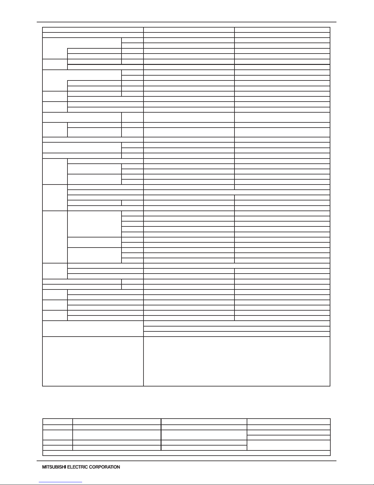
PQRY-P-T(S)LMU, Y(S)LMU (April 2017 Ver2)
WR2-17
© 2017 Mitsubishi Electric US, Inc.
1. SPECIFICATIONS
Note: *1 Nominal cooling conditions (subject to JIS B8615-1) *2 Nominal heating conditions (subject to JIS B8615-1) Unit converter
Indoor: 81degF D.B./ 66degF W.B. (27degC D.B./ 19degC W.B.) 68degF D.B. (20degC D.B.) BTU/h =kW x 3,412
Water Temp.: 86degF (30degC) 68degF (20degC)
cfm =m3/min x 35.31
lb =kg / 0.4536
Pipe length: 24-9/16ft.(7.5m) 25ft.(7.6m)
* Above specication data is subject to rounding
variation.
Level difference: 0ft.(0m) 0ft.(0m)
* Due to continuing improvement, above specications may be subject to change without notice.
Model PQRY-P168YLMU-A PQRY-P192YLMU-A
Power source 3-phase 3-wire 460 ±10% 60Hz 3-phase 3-wire 460 ±10% 60Hz
Cooling capacity (Nominal) *1 (460V)
Btu/h 168,000 192,000
kW 49.2 56.3
Power input kW 12.05 15.05
Current input A
16.8 20.9
Temp. range
of cooling
Indoor W.B.
59~75° F (15~24° C) 59~75° F (15~24° C)
Circulating water *3 50~113° F (10~45° C) 50~113° F (10~45° C)
Heating capacity (Nominal) *2 (460V)
Btu/h
188,000 215,000
kW
55.1 63
Power input kW 9.86 11.9
Current input A 13.7 16.5
Temp. range
of heating
Indoor D.B. 59~81° F (15~27° C) 59~81° F (15~27° C)
Circulating water *3 50~113° F (10~45° C) 50~113° F (10~45° C)
Indoor unit
connectable
Total capacity 50~150% of heat source unit capacity 50~150% of heat source unit capacity
Model / Quantity P06~P96/1~42 P06~P96/1~48
Sound pressure level (measured in anechoic
room)
dB <A> 56 58
Refrigerant
piping
diameter
High pressure in.(mm) 7/8 (22.2) Brazed 7/8 (22.2) Brazed
Low pressure in.(mm) 1-1/8 (28.58) Brazed 1-1/8 (28.58) Brazed
External nish Galvanized steel sheets Galvanized steel sheets
External dimension HxWxD
in. 57-1/8 x 34-11/16 x 21-11/16 43-5/16 x 34-11/16 x 21-11/16
mm 1,450 x 880 x 550 1,100 x 880 x 550
Net weight lbs(kg) 505 (229) 404 (183)
Heat
exchanger
Type Plate Plate
Water volume in plate
G 1.32 1.32
I 5 5
Water pressure Max.
psi 290 290
MPa 2 2
Compressor
Type Inverter scroll hermetic compressor Inverter scroll hermetic compressor
Manufacturer AC&R Works, MITSUBISH ELECTRIC CORPORATION
Starting method Inverter Inverter
Motor output kW 11.0 12.4
Lubricant MEL32 MEL32
Circulating
water *3
Water ow rate
G/h 1,902 1,902
G/min(gpm) 31.7 31.7
m3 / h 7.2 7.2
L/min 120 120
cfm 4.2 4.2
Pressure drop
psi 6.38 6.38
kPa 44 44
Operating volume range
G/h 1,189 ~ 3,054 1,189 ~ 3,054
G/min(gpm) 19.8 ~ 50.9 19.8 ~ 50.9
m3 / h 4.5 ~ 11.6 4.5 ~ 11.6
Protection
devices
High pressure protection High pressure sensor, High pressure switch at 4.15 MPa (601 psi)
Inverter circuit(comp) Over-heat protection, Over-current protection Over-heat protection, Over-current protection
Compressor Over-heat protection Over-heat protection
Minimum Circuit Ampacity(MCA) A 20 25
Maximum Overcurrent Protection(MOP) A 35 40
Refrigerant
Type x original charge R410A x 13 lbs + 4 oz (6.0 kg) R410A x 13 lbs + 4 oz (6.0 kg)
Control Indoor LEV and BC controller Indoor LEV and BC controller
Drawing
External KJ94T130 KJ94T130
Wiring KE94C952 KE94C952
Standard
attachment
Document Installation Manual Installation Manual
Accessory Details refer to External Drw Details refer to External Drw
Optional parts
Joint: CMY-Y102SS-G2, CMY-Y102LS-G2, CMY-Y202S-G2, CMY-Y302S-G2, CMY-R160-J1
Main BC controller: CMB-P108, 1010, 1013, 1016NU-GA1, 108, 1010, 1016NU-HA1
Sub BC controller: CMB-P104, 108NU-GB1, CMB-P1016NU-HB1
Remarks
Details on foundation work, duct work, insulation work, electrical wiring, power source switch, and other items
shall be referred to the Installation Manual.
The ambient temperature of the Heat Source Unit needs to be kept below 104°F DB(40° C DB).
The ambient relative humidity of the Heat Source Unit needs to be kept below 80%.
The Heat Source Unit should not be installed at outdoor.
Mount a strainer (more than 50 meshes) at the water inlet piping of the unit.
Factory furnished eld installed interlocking for the unit operation and water circuit.
A eld provided ow switch is required for minimum ow protection on each module, eld installed and wired to
TB8 (terminal 3-4).
*3 If using Circulating water temperatures that are between 23 and 50° F, Dip switch 3-9 must be turned
on and glycol must be used in the water loop to prevent freezing down to 5° F.
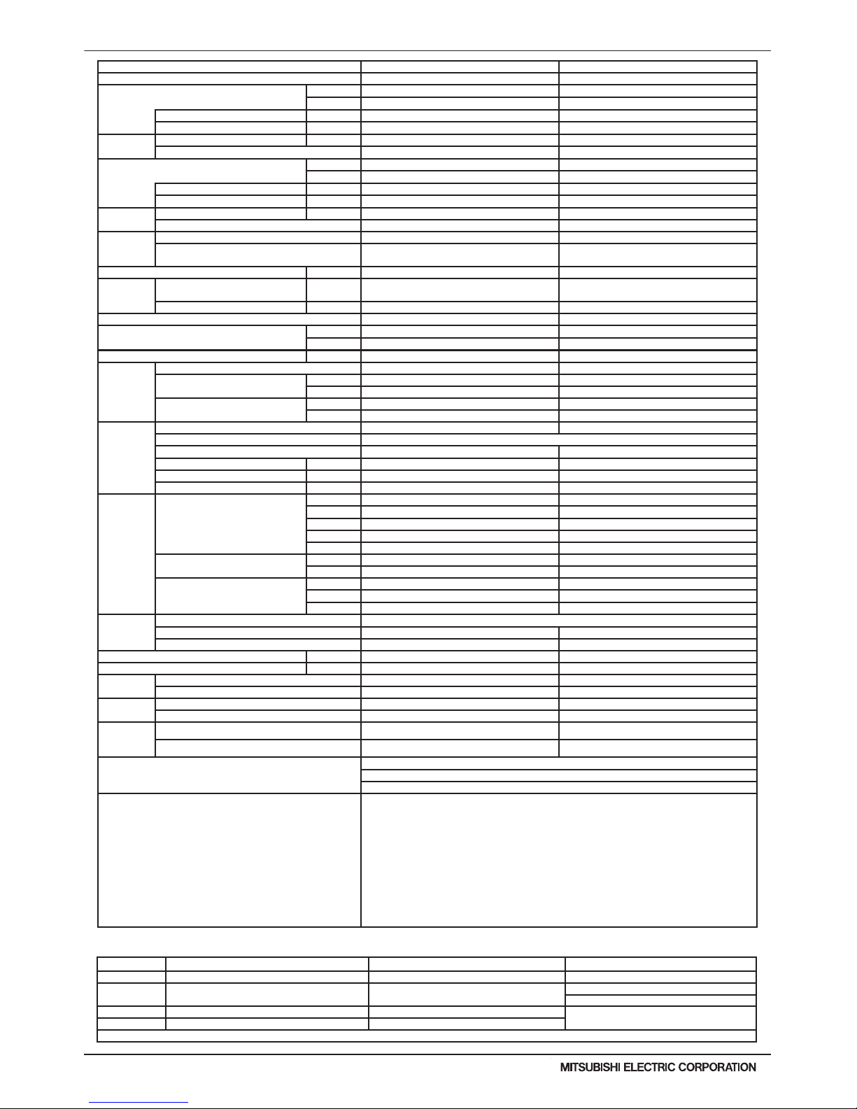
WR2-18
PQRY-P-T(S)LMU, Y(S)LMU (April 2017 Ver2)
© 2017 Mitsubishi Electric US, Inc.
1. SPECIFICATIONS
Note: *1 Nominal cooling conditions (subject to JIS B8615-1) *2 Nominal heating conditions (subject to JIS B8615-1) Unit converter
Indoor: 81degF D.B./ 66degF W.B. (27degC D.B./ 19degC W.B.) 68degF D.B. (20degC D.B.) BTU/h =kW x 3,412
Water Temp.: 86degF (30degC) 68degF (20degC)
cfm =m3/min x 35.31
lb =kg / 0.4536
Pipe length: 24-9/16ft.(7.5m) 25ft.(7.6m)
* Above specication data is subject to rounding
variation.
Level difference: 0ft.(0m) 0ft.(0m)
* Due to continuing improvement, above specications may be subject to change without notice.
Model PQRY-P216YLMU-A PQRY-P240YLMU-A
Power source 3-phase 3-wire 460 ±10% 60Hz 3-phase 3-wire 460 ±10% 60Hz
Cooling capacity (Nominal) *1 (460V)
Btu/h 216,000 240,000
kW 63.3 70.3
Power input kW 19.23 21.14
Current input A
26.8 29.4
Temp. range
of cooling
Indoor W.B. 59~75° F (15~24° C) 59~75° F (15~24° C)
Circulating water *3
50~113° F (10~45° C) 50~113° F (10~45° C)
Heating capacity (Nominal) *2 (460V)
Btu/h
243,000 270,000
kW 71.2 79.1
Power input kW 13.04 15.12
Current input A 18.1 21
Temp. range
of heating
Indoor D.B. 59~81° F (15~27° C) 59~81° F (15~27° C)
Circulating water *3 50~113° F (10~45° C) 50~113° F (10~45° C)
Indoor unit
connectable
Total capacity 50~150% of heat source unit capacity 50~150% of heat source unit capacity
Model / Quantity
P06~P96/2~50
(Connectable branch pipe number is max. 48.)
P06~P96/2~50
(Connectable branch pipe number is max. 48.)
Sound pressure level (measured in anechoic room) dB <A> 58 58
Refrigerant
piping
diameter
High pressure in.(mm)
7/8 (22.2) Brazed (1-1/8 (28.58)
Brazed for the part that exceeds 65 m)
7/8 (22.2) Brazed (1-1/8 (28.58)
Brazed for the part that exceeds 65 m)
Low pressure in.(mm) 1-1/8 (28.58) Brazed 1-3/8 (34.93) Brazed
External nish Galvanized steel sheets Galvanized steel sheets
External dimension HxWxD
in.
57-1/8 x 34-11/16 x 21-11/16 57-1/8 x 34-11/16 x 21-11/16
mm 1,450 x 880 x 550 1,450 x 880 x 550
Net weight lbs(kg) 571 (259) 571 (259)
Heat
exchanger
Type Plate Plate
Water volume in plate
G 2.64 2.64
I 10 10
Water pressure Max.
psi 290 290
MPa 2 2
Compressor
Type Inverter scroll hermetic compressor Inverter scroll hermetic compressor
Manufacturer AC&R Works, MITSUBISH ELECTRIC CORPORATION
Starting method Inverter Inverter
Motor output kW 14.5 16.1
Case heater kW 0.045 (240 V) 0.045 (240 V)
Lubricant MEL32 MEL32
Circulating
water *3
Water ow rate
G/h 3,044 3,044
G/min(gpm) 50.7 50.7
m3 / h 11.52 11.52
L/min 192 192
cfm 6.8 6.8
Pressure drop
psi 6.53 6.53
kPa 45 45
Operating volume range
G/h 1,585 ~ 3,804 1,585 ~ 3,804
G/min(gpm) 26.4 ~ 63.4 26.4 ~ 63.4
m3 / h 6.0 ~ 14.4 6.0 ~ 14.4
Protection
devices
High pressure protection High pressure sensor, High pressure switch at 4.15 MPa (601 psi)
Inverter circuit(comp) Over-heat protection, Over-current protection Over-heat protection, Over-current protection
Compressor Over-heat protection Over-heat protection
Minimum Circuit Ampacity(MCA) A 31 36
Maximum Overcurrent Protection(MOP) A 50 60
Refrigerant
Type x original charge R410A x 25 lbs + 13 oz (11.7 kg) R410A x 25 lbs + 13 oz (11.7 kg)
Control Indoor LEV and BC controller Indoor LEV and BC controller
Drawing
External KJ94T173 KJ94T173
Wiring KE94C952 KE94C952
Standard
attachment
Document Installation Manual Installation Manual
Accessory Details refer to External Drw Details refer to External Drw
Optional parts
Joint: CMY-Y102SS-G2, CMY-Y102LS-G2, CMY-Y202S-G2, CMY-Y302S-G2, CMY-R160-J1
Main BC controller: CMB-P108, 1010, 1013, 1016NU-GA1, 108, 1010, 1016NU-HA1
Sub BC controller: CMB-P104, 108NU-GB1, CMB-P1016NU-HB1
Remarks
Details on foundation work, duct work, insulation work, electrical wiring, power source switch, and other
items shall be referred to the Installation Manual.
The ambient temperature of the Heat Source Unit needs to be kept below 104°F DB(40° C DB).
The ambient relative humidity of the Heat Source Unit needs to be kept below 80%.
The Heat Source Unit should not be installed at outdoor.
Mount a strainer (more than 50 meshes) at the water inlet piping of the unit.
When the high pressure piping length is 65 m or less, use 7/8 (22.2) pipe.
When the high pressure piping length exceeds 65 m, use 7/8 (22.2) pipe until 65 m, use 1-1/8 (28.58)
pipe for the part that exceeds 65 m.
A eld provided ow switch is required for minimum ow protection on each module, eld installed and
wired to TB8 (terminal 3-4).
*3 If using Circulating water temperatures that are between 23 and 50° F, Dip switch 3-9 must be turned
on and glycol must be used in the water loop to prevent freezing down to 5° F.
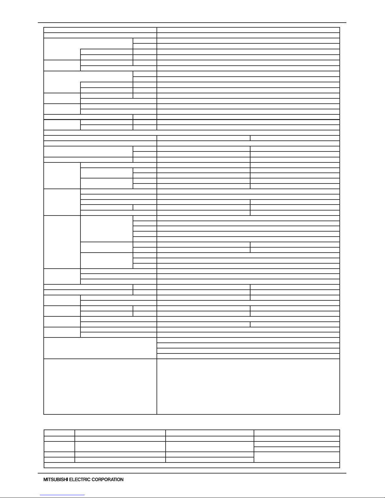
PQRY-P-T(S)LMU, Y(S)LMU (April 2017 Ver2)
WR2-19
© 2017 Mitsubishi Electric US, Inc.
1. SPECIFICATIONS
Note: *1 Nominal cooling conditions (subject to JIS B8615-1) *2 Nominal heating conditions (subject to JIS B8615-1) Unit converter
Indoor: 81degF D.B./ 66degF W.B. (27degC D.B./ 19degC W.B.) 68degF D.B. (20degC D.B.) BTU/h =kW x 3,412
Water Temp.: 86degF (30degC) 68degF (20degC)
cfm =m3/min x 35.31
lb =kg / 0.4536
Pipe length: 24-9/16ft.(7.5m) 25ft.(7.6m)
* Above specication data is subject to rounding
variation.
Level difference: 0ft.(0m) 0ft.(0m)
* Due to continuing improvement, above specications may be subject to change without notice.
Model PQRY-P144YSLMU-A
Power source 3-phase 3-wire 460 ±10% 60Hz
Cooling capacity (Nominal) *1 (460V)
Btu/h 144,000
kW 42.2
Power input kW 7.11
Current input A 9.9
Temp. range of
cooling
Indoor W.B. 59~75° F (15~24° C)
Circulating water *3 50~113° F (10~45° C)
Heating capacity (Nominal) *2 (460V)
Btu/h 160,000
kW 46.9
Power input kW 7.45
Current input A 10.3
Temp. range of
heating
Indoor D.B. 59~81° F (15~27° C)
Circulating water *3 50~113° F (10~45° C)
Indoor unit
connectable
Total capacity 50~150% of heat source unit capacity
Model / Quantity P06~P96/1~36
Sound pressure level (measured in anechoic room) dB <A> 49
Refrigerant piping
diameter
High pressure in.(mm) 7/8 (22.2) Brazed
Low pressure in.(mm) 1-1/8 (28.58) Brazed
Module Set
Module PQRY-P72YLMU-A PQRY-P72YLMU-A
External nish Galvanized steel sheets
External dimension HxWxD
in. 43-5/16 x 34-11/16 x 21-11/16 43-5/16 x 34-11/16 x 21-11/16
mm 1,100 x 880 x 550 1,100 x 880 x 550
Net weight lbs(kg) 404 (183) 404 (183)
Heat exchanger
Type Plate Plate
Water volume in plate
G 1.32 1.32
I 5 5
Water pressure Max.
psi 290 290
MPa 2 2
Compressor
Type Inverter scroll hermetic compressor
Manufacturer AC&R Works, MITSUBISHI ELECTRIC CORPORATION
Starting method Inverter Inverter
Motor output kW 4.3 4.3
Lubricant MEL32 MEL32
Circulating water *3
Water ow rate
G/h 1,522 + 1,522
G/min(gpm) 25.4 + 25.4
m3 / h 5.76 + 5.76
L/min 96 + 96
cfm 3.4 + 3.4
Pressure drop
psi 3.48 3.48
kPa 24 24
Operating volume range
range
G/h 793 + 793 ~ 1,902 + 1,902
G/min(gpm) 13.2 + 13.2 ~ 31.7 + 31.7
m3 / h 3.0 + 3.0 ~ 7.2 + 7.2
Protection devices
High pressure protection High pressure sensor, High pressure switch at 4.15 MPa (601 psi)
Inverter circuit(comp) Over-heat protection, Over-current protection
Compressor Over-heat protection
Minimum Circuit Ampacity(MCA) A 6 6
Maximum Overcurrent Protection(MOP) A 15 15
Refrigerant
Type x original charge R410A x 11 lbs + 1 oz (5.0 kg) R410A x 11 lbs + 1 oz (5.0 kg)
Control Indoor LEV and BC controller
Pipe between unit
and distributor
High pressure in.(mm) 5/8 (15.88) Brazed 5/8 (15.88) Brazed
Low pressure in.(mm) - 3/4 (19.05) Brazed
Drawing
External KJ94T153
Wiring KE94C952 KE94C952
Standard
attachment
Document Installation Manual
Accessory Details refer to External Drw
Optional parts
Heat Source Twinning kit: CMY-Q100CBK2
Joint: CMY-Y102SS-G2, CMY-Y102LS-G2, CMY-Y202S-G2, CMY-R160-J1
Main BC controller: CMB-P108, 1010, 1013, 1016NU-GA1, 108, 1010, 1016NU-HA1
Sub BC controller: CMB-P104, 108NU-GB1, CMB-P1016NU-HB1
Remarks
Details on foundation work, duct work, insulation work, electrical wiring, power source switch, and other
items shall be referred to the Installation Manual.
The ambient temperature of the Heat Source Unit needs to be kept below 104°F DB(40° C DB).
The ambient relative humidity of the Heat Source Unit needs to be kept below 80%.
The Heat Source Unit should not be installed at outdoor.
Mount a strainer (more than 50 meshes) at the water inlet piping of the unit.
The Heat Source twinning kit (low pressure) should be connected to the low pressure side of the heat
source unit.
A eld provided ow switch is required for minimum ow protection on each module, eld installed and
wired to TB8 (terminal 3-4).
*3 If using Circulating water temperatures that are between 23 and 50° F, Dip switch 3-9 must be turned
on and glycol must be used in the water loop to prevent freezing down to 5° F.

WR2-20
PQRY-P-T(S)LMU, Y(S)LMU (April 2017 Ver2)
© 2017 Mitsubishi Electric US, Inc.
1. SPECIFICATIONS
Note: *1 Nominal cooling conditions (subject to JIS B8615-1) *2 Nominal heating conditions (subject to JIS B8615-1) Unit converter
Indoor: 81degF D.B./ 66degF W.B. (27degC D.B./ 19degC W.B.) 68degF D.B. (20degC D.B.) BTU/h =kW x 3,412
Water Temp.: 86degF (30degC) 68degF (20degC)
cfm =m3/min x 35.31
lb =kg / 0.4536
Pipe length: 24-9/16ft.(7.5m) 25ft.(7.6m)
* Above specication data is subject to rounding
variation.
Level difference: 0ft.(0m) 0ft.(0m)
* Due to continuing improvement, above specications may be subject to change without notice.
Model PQRY-P168YSLMU-A
Power source 3-phase 3-wire 460 ±10% 60Hz
Cooling capacity (Nominal) *1 (460V)
Btu/h 168,000
kW 49.2
Power input kW 9.33
Current input A 13
Temp. range of
cooling
Indoor W.B. 59~75° F (15~24° C)
Circulating water *3 50~113° F (10~45° C)
Heating capacity (Nominal) *2 (460V)
Btu/h 188,000
kW 55.1
Power input kW 9.34
Current input A 13
Temp. range of
heating
Indoor D.B. 59~81° F (15~27° C)
Circulating water *3 50~113° F (10~45° C)
Indoor unit
connectable
Total capacity 50~150% of heat source unit capacity
Model / Quantity P06~P96/1~42
Sound pressure level (measured in anechoic room) dB <A> 50
Refrigerant piping
diameter
High pressure in.(mm) 7/8 (22.2) Brazed
Low pressure in.(mm) 1-1/8 (28.58) Brazed
Module Set
Module PQRY-P96YLMU-A PQRY-P72YLMU-A
External nish Galvanized steel sheets
External dimension HxWxD
in. 43-5/16 x 34-11/16 x 21-11/16 43-5/16 x 34-11/16 x 21-11/16
mm 1,100 x 880 x 550 1,100 x 880 x 550
Net weight lbs(kg) 404 (183) 404 (183)
Heat exchanger
Type Plate Plate
Water volume in plate
G 1.32 1.32
I 5 5
Water pressure Max.
psi 290 290
MPa 2 2
Compressor
Type Inverter scroll hermetic compressor
Manufacturer AC&R Works, MITSUBISHI ELECTRIC CORPORATION
Starting method Inverter Inverter
Motor output kW 6.0 4.3
Lubricant MEL32 MEL32
Circulating water *3
Water ow rate
G/h 1,522 + 1,522
G/min(gpm) 25.4 + 25.4
m3 / h 5.76 + 5.76
L/min 96 + 96
cfm 3.4 + 3.4
Pressure drop
psi 3.48 3.48
kPa 24 24
Operating volume range
G/h 793 + 793 ~ 1,902 + 1,902
G/min(gpm) 13.2 + 13.2 ~ 31.7 + 31.7
m3 / h 3.0 + 3.0 ~ 7.2 + 7.2
Protection devices
High pressure protection High pressure sensor, High pressure switch at 4.15 MPa (601 psi)
Inverter circuit(comp) Over-heat protection, Over-current protection
Compressor Over-heat protection
Minimum Circuit Ampacity(MCA) A 9 6
Maximum Overcurrent Protection(MOP) A 15 15
Refrigerant
Type x original charge R410A x 11 lbs + 1 oz (5.0 kg) R410A x 11 lbs + 1 oz (5.0 kg)
Control Indoor LEV and BC controller
Pipe between unit
and distributor
High pressure in.(mm) 3/4 (19.05) Brazed 3/4 (19.05) Brazed
Low pressure in.(mm) - 7/8 (22.2) Brazed
Drawing
External KJ94T153
Wiring KE94C952 KE94C952
Standard
Attachment
Document Installation Manual
Accessory Details refer to External Drw
Optional parts
Heat Source Twinning kit: CMY-Q100CBK2
Joint: CMY-Y102SS-G2, CMY-Y102LS-G2, CMY-Y202S-G2, CMY-Y302S-G2, CMY-R160-J1
Main BC controller: CMB-P108, 1010, 1013, 1016NU-GA1, 108, 1010, 1016NU-HA1
Sub BC controller: CMB-P104, 108NU-GB1, CMB-P1016NU-HB1
Remarks
Details on foundation work, duct work, insulation work, electrical wiring, power source switch, and other
items shall be referred to the Installation Manual.
The ambient temperature of the Heat Source Unit needs to be kept below 104°F DB(40° C DB).
The ambient relative humidity of the Heat Source Unit needs to be kept below 80%.
The Heat Source Unit should not be installed at outdoor.
Mount a strainer (more than 50 meshes) at the water inlet piping of the unit.
The Heat Source twinning kit (low pressure) should be connected to the low pressure side of the heat
source unit.
A eld provided ow switch is required for minimum ow protection on each module, eld installed and
wired to TB8 (terminal 3-4).
*3 If using Circulating water temperatures that are between 23 and 50° F, Dip switch 3-9 must be turned
on and glycol must be used in the water loop to prevent freezing down to 5° F.
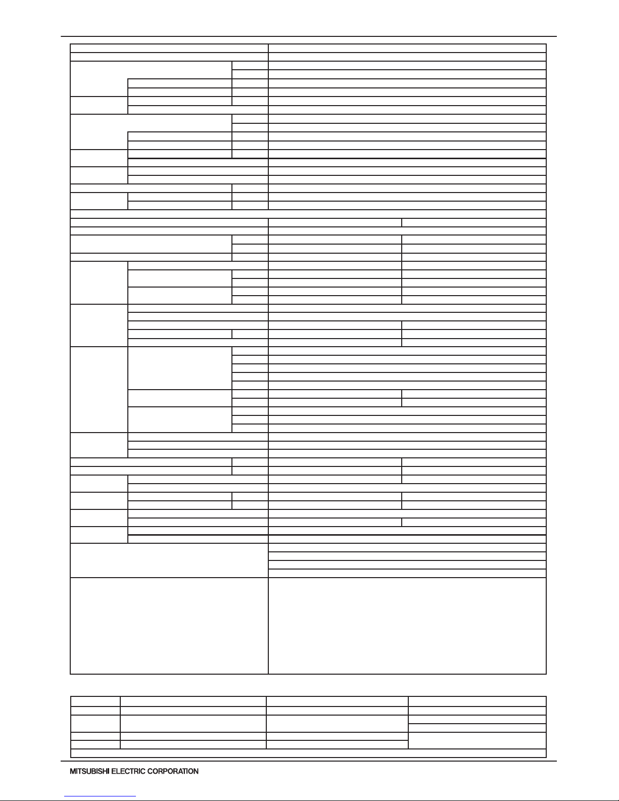
PQRY-P-T(S)LMU, Y(S)LMU (April 2017 Ver2)
WR2-21
© 2017 Mitsubishi Electric US, Inc.
1. SPECIFICATIONS
Note: *1 Nominal cooling conditions (subject to JIS B8615-1) *2 Nominal heating conditions (subject to JIS B8615-1) Unit converter
Indoor: 81degF D.B./ 66degF W.B. (27degC D.B./ 19degC W.B.) 68degF D.B. (20degC D.B.) BTU/h =kW x 3,412
Water Temp.: 86degF (30degC) 68degF (20degC)
cfm =m3/min x 35.31
lb =kg / 0.4536
Pipe length: 24-9/16ft.(7.5m) 25ft.(7.6m)
* Above specication data is subject to rounding
variation.
Level difference: 0ft.(0m) 0ft.(0m)
* Due to continuing improvement, above specications may be subject to change without notice.
Model PQRY-P192YSLMU-A
Power source 3-phase 3-wire 460 ±10% 60Hz
Cooling capacity (Nominal) *1 (460V)
Btu/h 192,000
kW 56.3
Power input kW 11.3
Current input A 15.7
Temp. range of
cooling
Indoor W.B. 59~75° F (15~24° C)
Circulating water *3 50~113° F (10~45° C)
Heating capacity (Nominal) *2 (460V)
Btu/h 215,000
kW 63
Power input kW 11.02
Current input A 15.3
Temp. range of
heating
Indoor D.B. 59~81° F (15~27° C)
Circulating water *3 50~113° F (10~45° C)
Indoor unit
connectable
Total capacity 50~150% of heat source unit capacity
Model / Quantity P06~P96/1~48
Sound pressure level (measured in anechoic room) dB <A> 51
Refrigerant piping
diameter
High pressure in.(mm) 7/8 (22.2) Brazed
Low pressure in.(mm) 1-1/8 (28.58) Brazed
Module Set
Module PQRY-P96YLMU-A PQRY-P96YLMU-A
External nish Galvanized steel sheets
External dimension HxWxD
in. 43-5/16 x 34-11/16 x 21-11/16 43-5/16 x 34-11/16 x 21-11/16
mm 1,100 x 880 x 550 1,100 x 880 x 550
Net weight lbs(kg) 404 (183) 404 (183)
Heat exchanger
Type Plate Plate
Water volume in plate
G 1.32 1.32
I 5 5
Water pressure Max.
psi 290 290
MPa 2 2
Compressor
Type Inverter scroll hermetic compressor
Manufacturer AC&R Works, MITSUBISHI ELECTRIC CORPORATION
Starting method Inverter Inverter
Motor output kW
6.0 6.0
Lubricant MEL32 MEL32
Circulating water *3
Water ow rate
G/h 1,522 + 1,522
G/min(gpm) 25.4 + 25.4
m3 / h 5.76 + 5.76
L/min 96 + 96
cfm 3.4 + 3.4
Pressure drop
psi 3.48 3.48
kPa 24 24
Operating volume range
G/h 793 + 793 ~ 1,902 + 1,902
G/min(gpm) 13.2 + 13.2 ~ 31.7 + 31.7
m3 / h 3.0 + 3.0 ~ 7.2 + 7.2
Protection devices
High pressure protection High pressure sensor, High pressure switch at 4.15 MPa (601 psi)
Inverter circuit(comp) Over-heat protection, Over-current protection
Compressor Over-heat protection
Minimum Circuit Ampacity(MCA) A 9 9
Maximum Overcurrent Protection(MOP) A 15 15
Refrigerant
Type x original charge R410A x 11 lbs + 1 oz (5.0 kg) R410A x 11 lbs + 1 oz (5.0 kg)
Control Indoor LEV and BC controller
Pipe between unit
and distributor
High pressure in.(mm) 3/4 (19.05) Brazed 3/4 (19.05) Brazed
Low pressure in.(mm) - 7/8 (22.2) Brazed
Drawing
External KJ94T153
Wiring KE94C952 KE94C952
Standard
attachment
Document Installation Manual
Accessory Details refer to External Drw
Optional parts
Heat Source Twinning kit: CMY-Q100CBK2
Joint: CMY-Y102SS-G2, CMY-Y102LS-G2, CMY-Y202S-G2, CMY-Y302S-G2, CMY-R160-J1
Main BC controller: CMB-P108, 1010, 1013, 1016NU-GA1, 108, 1010, 1016NU-HA1
Sub BC controller: CMB-P104, 108NU-GB1, CMB-P1016NU-HB1
Remarks
Details on foundation work, duct work, insulation work, electrical wiring, power source switch, and
other items shall be referred to the Installation Manual.
The ambient temperature of the Heat Source Unit needs to be kept below 104°F DB(40° C DB).
The ambient relative humidity of the Heat Source Unit needs to be kept below 80%.
The Heat Source Unit should not be installed at outdoor.
Mount a strainer (more than 50 meshes) at the water inlet piping of the unit.
The Heat Source twinning kit (low pressure) should be connected to the low pressure side of the
heat source unit.
A eld provided ow switch is required for minimum ow protection on each module, eld installed
and wired to TB8 (terminal 3-4).
*3 If using Circulating water temperatures that are between 23 and 50° F, Dip switch 3-9 must be
turned
on and glycol must be used in the water loop to prevent freezing down to 5° F.
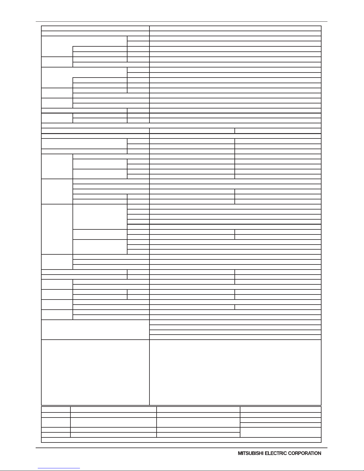
WR2-22
PQRY-P-T(S)LMU, Y(S)LMU (April 2017 Ver2)
© 2017 Mitsubishi Electric US, Inc.
1. SPECIFICATIONS
Note: *1 Nominal cooling conditions (subject to JIS B8615-1) *2 Nominal heating conditions (subject to JIS B8615-1) Unit converter
Indoor: 81degF D.B./ 66degF W.B. (27degC D.B./ 19degC W.B.) 68degF D.B. (20degC D.B.) BTU/h =kW x 3,412
Water Temp.: 86degF (30degC) 68degF (20degC)
cfm =m3/min x 35.31
lb =kg / 0.4536
Pipe length: 24-9/16ft.(7.5m) 25ft.(7.6m)
* Above specication data is subject to rounding
variation.
Level difference: 0ft.(0m) 0ft.(0m)
* Due to continuing improvement, above specications may be subject to change without notice.
Model PQRY-P216YSLMU-A
Power source 3-phase 3-wire 460 ±10% 60Hz
Cooling capacity (Nominal) *1 (460V)
Btu/h 216,000
kW 63.3
Power input kW 14.03
Current input A 19.5
Temp. range of
cooling
Indoor W.B. 59~75° F (15~24° C)
Circulating water *3 50~113° F (10~45° C)
Heating capacity (Nominal) *2 (460V)
Btu/h 243,000
kW 71.2
Power input kW 12.88
Current input A 17.9
Temp. range of
heating
Indoor D.B. 59~81° F (15~27° C)
Circulating water *3 50~113° F (10~45° C)
Indoor unit
connectable
Total capacity 50~150% of heat source unit capacity
Model / Quantity P06~P96/2~50 (Connectable branch pipe number is max. 48.)
Sound pressure level (measured in anechoic room) dB <A> 55
Refrigerant piping
diameter
High pressure in.(mm) 7/8 (22.2) Brazed (1-1/8 (28.58) Brazed for the part that exceeds 65 m)
Low pressure in.(mm) 1-1/8 (28.58) Brazed
Module Set
Module PQRY-P120YLMU-A PQRY-P96YLMU-A
External nish Galvanized steel sheets
External dimension HxWxD
in. 43-5/16 x 34-11/16 x 21-11/16 43-5/16 x 34-11/16 x 21-11/16
mm 1,100 x 880 x 550 1,100 x 880 x 550
Net weight lbs(kg) 404 (183) 404 (183)
Heat exchanger
Type Plate Plate
Water volume in plate
G 1.32 1.32
I 5 5
Water pressure Max.
psi 290 290
MPa 2 2
Compressor
Type Inverter scroll hermetic compressor
Manufacturer AC&R Works, MITSUBISHI ELECTRIC CORPORATION
Starting method Inverter Inverter
Motor output kW 7.7 6.0
Lubricant MEL32 MEL32
Circulating
water *3
Water ow rate
G/h 1,522 + 1,522
G/min(gpm) 25.4 + 25.4
m3 / h 5.76 + 5.76
L/min 96 + 96
cfm 3.4 + 3.4
Pressure drop
psi 3.48 3.48
kPa 24 24
Operating volume range
G/h 793 + 793 ~ 1,902 + 1,902
G/min(gpm) 13.2 + 13.2 ~ 31.7 + 31.7
m3 / h 3.0 + 3.0 ~ 7.2 + 7.2
Protection
devices
High pressure protection High pressure sensor, High pressure switch at 4.15 MPa (601 psi)
Inverter circuit(comp) Over-heat protection, Over-current protection
Compressor Over-heat protection
Minimum Circuit Ampacity(MCA) A 13 9
Maximum Overcurrent Protection(MOP) A 20 15
Refrigerant
Type x original charge R410A x 11 lbs + 1 oz (5.0 kg) R410A x 11 lbs + 1 oz (5.0 kg)
Control Indoor LEV and BC controller
Pipe between unit
and distributor
High pressure in.(mm) 3/4 (19.05) Brazed 3/4 (19.05) Brazed
Low pressure in.(mm) - 7/8 (22.2) Brazed
Drawing
External KJ94T153
Wiring KE94C952 KE94C952
Standard
attachment
Document Installation Manual
Accessory Details refer to External Drw
Optional parts
Heat Source Twinning kit: CMY-Q100CBK2
Joint: CMY-Y102SS-G2, CMY-Y102LS-G2, CMY-Y202S-G2, CMY-Y302S-G2, CMY-R160-J1
Main BC controller: CMB-P108, 1010, 1013, 1016NU-GA1, 108, 1010, 1016NU-HA1
Sub BC controller: CMB-P104, 108NU-GB1, CMB-P1016NU-HB1
Remarks
Details on foundation work, duct work, insulation work, electrical wiring, power source switch, and other
items shall be referred to the Installation Manual.
The ambient temperature of the Heat Source Unit needs to be kept below 104°F DB(40° C DB). The
ambient relative humidity of the Heat Source Unit needs to be kept below 80%.
The Heat Source Unit should not be installed at outdoor.
Mount a strainer (more than 50 meshes) at the water inlet piping of the unit.
The Heat Source twinning kit (low pressure) should be connected to the low pressure side of the heat
source unit. Install the supplied insulation material to the unused drain-socket.
When installing insulation material around both water and refrigerant piping, follow the installation manual.
When the high pressure piping length is 65 m or less, use 7/8 (22.2) pipe. When the high pressure piping
length exceeds 65 m, use 7/8 (22.2) pipe until 65 m, use 1-1/8 (28.58) pipe for the part that exceeds 65m.
A eld provided ow switch is required for minimum ow protection on each module, eld installed and
wired to TB8 (terminal 3-4).
*3 If using Circulating water temperatures that are between 23 and 50° F, Dip switch 3-9 must be turned
on and glycol must be used in the water loop to prevent freezing down to 5° F.
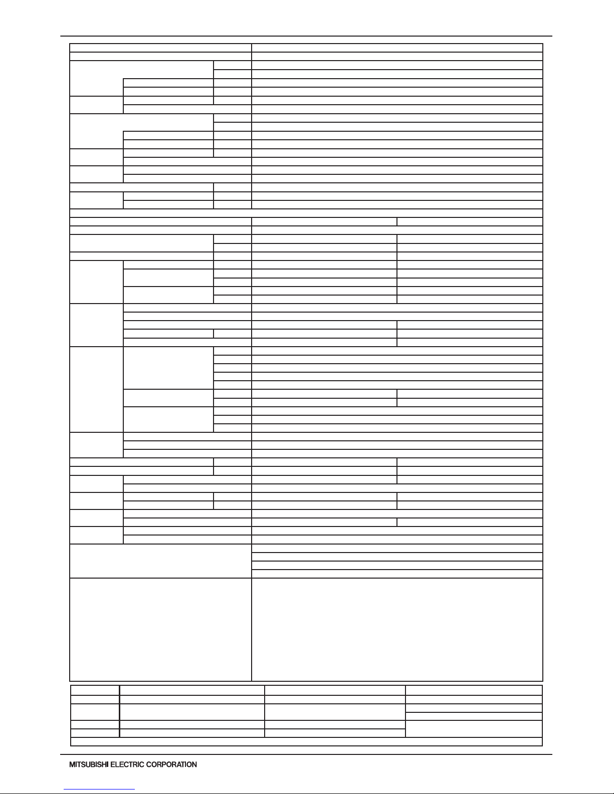
PQRY-P-T(S)LMU, Y(S)LMU (April 2017 Ver2)
WR2-23
© 2017 Mitsubishi Electric US, Inc.
1. SPECIFICATIONS
Note: *1 Nominal cooling conditions (subject to JIS B8615-1) *2 Nominal heating conditions (subject to JIS B8615-1) Unit converter
Indoor: 81degF D.B./ 66degF W.B. (27degC D.B./ 19degC W.B.) 68degF D.B. (20degC D.B.) BTU/h =kW x 3,412
Water Temp.: 86degF (30degC) 68degF (20degC)
cfm =m3/min x 35.31
lb =kg / 0.4536
Pipe length: 24-9/16ft.(7.5m) 25ft.(7.6m)
* Above specication data is subject to rounding
variation.
Level difference: 0ft.(0m) 0ft.(0m)
* Due to continuing improvement, above specications may be subject to change without notice.
Model PQRY-P240YSLMU-A
Power source 3-phase 3-wire 460 ±10% 60Hz
Cooling capacity (Nominal) *1 (460V)
Btu/h 240,000
kW 70.3
Power input kW 16.89
Current input A
23.5
Temp. range of
cooling
Indoor W.B. 59~75° F (15~24° C)
Circulating water *3
50~113° F (10~45° C)
Heating capacity (Nominal) *2 (460V)
Btu/h
270,000
kW 79.1
Power input kW 14.58
Current input A 20.3
Temp. range of
heating
Indoor D.B. 59~81° F (15~27° C)
Circulating water *3 50~113° F (10~45° C)
Indoor unit
connectable
Total capacity 50~150% of heat source unit capacity
Model / Quantity P06~P96/2~50 (Connectable branch pipe number is max. 48.)
Sound pressure level (measured in anechoic room) dB <A> 57
Refrigerant piping
diameter
High pressure in.(mm) 7/8 (22.2) Brazed (1-1/8 (28.58) Brazed for the part that exceeds 65 m)
Low pressure in.(mm) 1-3/8 (34.93) Brazed
Module Set
Module PQRY-P120YLMU-A PQRY-P120YLMU-A
External nish Galvanized steel sheets
External dimension HxWxD
in.
43-5/16 x 34-11/16 x 21-11/16 43-5/16 x 34-11/16 x 21-11/16
mm 1,100 x 880 x 550 1,100 x 880 x 550
Net weight lbs(kg) 404 (183) 404 (183)
Heat exchanger
Type Plate Plate
Water volume in plate
G 1.32 1.32
I 5.0 5.0
Water pressure Max.
psi 290 290
MPa 2.0 2.0
Compressor
Type Inverter scroll hermetic compressor
Manufacturer AC&R Works, MITSUBISHI ELECTRIC CORPORATION
Starting method Inverter Inverter
Motor output kW 7.7 7.7
Lubricant MEL32 MEL32
Circulating water
*3
Water ow rate
G/h 1,522 + 1,522
G/min(gpm) 25.4 + 25.4
m3 / h 5.76 + 5.76
L/min 96 + 96
cfm 3.4 + 3.4
Pressure drop
psi 3.48 3.48
kPa 24 24
Operating volume range
G/h 793 + 793 ~ 1,902 + 1,902
G/min(gpm) 13.2 + 13.2 ~ 31.7 + 31.7
m3 / h 3.0 + 3.0 ~ 7.2 + 7.2
Protection devices
High pressure protection High pressure sensor, High pressure switch at 4.15 MPa (601 psi)
Inverter circuit(comp) Over-heat protection, Over-current protection
Compressor Over-heat protection
Minimum Circuit Ampacity(MCA) A 13 13
Maximum Overcurrent Protection(MOP) A 20 20
Refrigerant
Type x original charge R410A x 11 lbs + 1 oz (5.0 kg) R410A x 11 lbs + 1 oz (5.0 kg)
Control Indoor LEV and BC controller
Pipe between unit
and distributor
High pressure in.(mm) 3/4 (19.05) Brazed 3/4 (19.05) Brazed
Low pressure in.(mm) - 7/8 (22.2) Brazed
Drawing
External KJ94T153
Wiring KE94C952 KE94C952
Standard
attachment
Document Installation Manual
Accessory Details refer to External Drw
Optional parts
Heat Source Twinning kit: CMY-Q100CBK2
Joint: CMY-Y102SS-G2, CMY-Y102LS-G2, CMY-Y202S-G2, CMY-Y302S-G2, CMY-R160-J1
Main BC controller: CMB-P108, 1010, 1013, 1016NU-GA1, 108, 1010, 1016NU-HA1
Sub BC controller: CMB-P104, 108NU-GB1, CMB-P1016NU-HB1
Remarks
Details on foundation work, duct work, insulation work, electrical wiring, power source switch, and other
items shall be referred to the Installation Manual.
The ambient temperature of the Heat Source Unit needs to be kept below 104°F DB(40° C DB). The
ambient relative humidity of the Heat Source Unit needs to be kept below 80%.
The Heat Source Unit should not be installed at outdoor. Mount a strainer (more than 50 meshes) at the
water inlet piping of the unit.The Heat Source twinning kit (low pressure) should be connected to the low
pressure side of the heat source unit. Install the supplied insulation material to the unused drain-socket.
When installing insulation material around both water and refrigerant piping, follow the installation manual.
When the high pressure piping length is 65 m or less, use 7/8 (22.2) pipe. When the high pressure piping
length exceeds 65 m, use 7/8 (22.2) pipe until 65 m, use 1-1/8 (28.58) pipe for the part that exceeds 65m.
A eld provided ow switch is required for minimum ow protection on each module, eld installed and
wired to TB8 (terminal 3-4).
*3 If using Circulating water temperatures that are between 23 and 50° F, Dip switch 3-9 must be turned on
and glycol must be used in the water loop to prevent freezing down to 5° F.
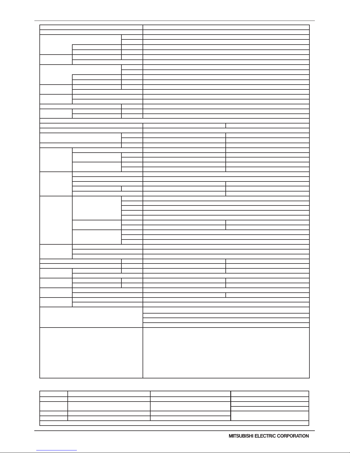
WR2-24
PQRY-P-T(S)LMU, Y(S)LMU (April 2017 Ver2)
© 2017 Mitsubishi Electric US, Inc.
1. SPECIFICATIONS
Note: *1 Nominal cooling conditions (subject to JIS B8615-1) *2 Nominal heating conditions (subject to JIS B8615-1) Unit converter
Indoor: 81degF D.B./ 66degF W.B. (27degC D.B./ 19degC W.B.) 68degF D.B. (20degC D.B.) BTU/h =kW x 3,412
Water Temp.: 86degF (30degC) 68degF (20degC)
cfm =m3/min x 35.31
lb =kg / 0.4536
Pipe length: 24-9/16ft.(7.5m) 25ft.(7.6m)
* Above specication data is subject to rounding
variation.
Level difference: 0ft.(0m) 0ft.(0m)
* Due to continuing improvement, above specications may be subject to change without notice.
Model PQRY-P288YSLMU-A
Power source 3-phase 3-wire 460 ±10% 60Hz
Cooling capacity (Nominal) *1 (460V)
Btu/h 288,000
kW 84.4
Power input kW 20.42
Current input A 28.4
Temp. range of
cooling
Indoor W.B. 59~75° F (15~24° C)
Circulating water *3 50~113° F (10~45° C)
Heating capacity (Nominal) *2 (460V)
Btu/h 323,000
kW 94.7
Power input kW 17.5
Current input A 24.4
Temp. range of
heating
Indoor D.B. 59~81° F (15~27° C)
Circulating water *3 50~113° F (10~45° C)
Indoor unit
connectable
Total capacity 50~150% of heat source unit capacity
Model / Quantity P06~P96/2~50 (Connectable branch pipe number is max. 48.)
Sound pressure level (measured in anechoic room) dB <A> 57
Refrigerant piping
diameter
High pressure in.(mm) 1-1/8 (28.58) Brazed
Low pressure in.(mm) 1-3/8 (34.93) Brazed
Module Set
Module PQRY-P144YLMU-A PQRY-P144YLMU-A
External nish Galvanized steel sheets
External dimension HxWxD
in. 57-1/8 x 34-11/16 x 21-11/16 57-1/8 x 34-11/16 x 21-11/16
mm 1,450 x 880 x 550 1,450 x 880 x 550
Net weight lbs(kg) 505 (229) 505 (229)
Heat exchanger
Type Plate Plate
Water volume in plate
G 1.32 1.32
I 5 5
Water pressure Max.
psi 290 290
MPa 2 2
Compressor
Type Inverter scroll hermetic compressor
Manufacturer AC&R Works, MITSUBISHI ELECTRIC CORPORATION
Starting method Inverter Inverter
Motor output kW 9.5 9.5
Lubricant MEL32 MEL32
Circulating water *3
Water ow rate
G/h 1,902 + 1,902
G/min(gpm) 31.7 + 31.7
m3 / h 7.20 + 7.20
L/min 120 + 120
cfm 4.2 + 4.2
Pressure drop
psi 6.38 6.38
kPa 44 44
Operating volume range
G/h 1,189 + 1,189 ~ 3,054 + 3,054
G/min(gpm) 19.8 + 19.8 ~ 50.9 + 50.9
m3 / h 4.5 + 4.5 ~ 11.6 + 11.6
Protection devices
High pressure protection High pressure sensor, High pressure switch at 4.15 MPa (601 psi)
Inverter circuit(comp) Over-heat protection, Over-current protection
Compressor Over-heat protection
Minimum Circuit Ampacity(MCA) A 16 16
Maximum Overcurrent Protection(MOP) A 25 25
Refrigerant
Type x original charge R410A x 13 lbs + 4 oz (6.0 kg) R410A x 13 lbs + 4 oz (6.0 kg)
Control Indoor LEV and BC controller
Pipe between unit
and distributor
High pressure in.(mm) 7/8 (22.2) Brazed 7/8 (22.2) Brazed
Low pressure in.(mm) - 1-1/8 (28.58) Brazed
Drawing
External KJ94T154
Wiring KE94C952 KE94C952
Standard
Attachment
Document Installation Manual
Accessory Details refer to External Drw
Optional parts
Heat Source Twinning kit: CMY-Q200CBK
Joint: CMY-Y102SS-G2, CMY-Y102LS-G2, CMY-Y202S-G2, CMY-Y302S-G2, CMY-R160-J1
Main BC controller: CMB-P108, 1010, 1016NU-HA1
Sub BC controller: CMB-P104, 108NU-GB1, CMB-P1016NU-HB1
Remarks
Details on foundation work, duct work, insulation work, electrical wiring, power source switch, and other
items shall be referred to the Installation Manual.
The ambient temperature of the Heat Source Unit needs to be kept below 104°F DB(40° C DB).
The ambient relative humidity of the Heat Source Unit needs to be kept below 80%.
The Heat Source Unit should not be installed at outdoor.
Mount a strainer (more than 50 meshes) at the water inlet piping of the unit.
The Heat Source twinning kit (low pressure) should be connected to the low pressure side of the heat
source unit.
A eld provided ow switch is required for minimum ow protection on each module, eld installed and
wired to TB8 (terminal 3-4).
*3 If using Circulating water temperatures that are between 23 and 50° F, Dip switch 3-9 must be turned
on and glycol must be used in the water loop to prevent freezing down to 5° F.
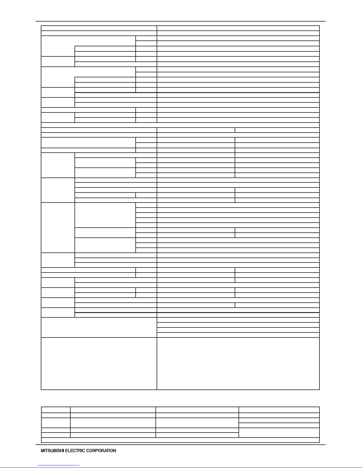
PQRY-P-T(S)LMU, Y(S)LMU (April 2017 Ver2)
WR2-25
© 2017 Mitsubishi Electric US, Inc.
1. SPECIFICATIONS
Note: *1 Nominal cooling conditions (subject to JIS B8615-1) *2 Nominal heating conditions (subject to JIS B8615-1) Unit converter
Indoor: 81degF D.B./ 66degF W.B. (27degC D.B./ 19degC W.B.) 68degF D.B. (20degC D.B.) BTU/h =kW x 3,412
Water Temp.: 86degF (30degC) 68degF (20degC)
cfm =m3/min x 35.31
lb =kg / 0.4536
Pipe length: 24-9/16ft.(7.5m) 25ft.(7.6m)
* Above specication data is subject to rounding
variation.
Level difference: 0ft.(0m) 0ft.(0m)
* Due to continuing improvement, above specications may be subject to change without notice.
Model PQRY-P312YSLMU-A
Power source 3-phase 3-wire 460 ±10% 60Hz
Cooling capacity (Nominal) *1 (460V)
Btu/h 312,000
kW 91.4
Power input kW 23.41
Current input A 32.6
Temp. range of
cooling
Indoor W.B. 59~75° F (15~24° C)
Circulating water *3 50~113° F (10~45° C)
Heating capacity (Nominal) *2 (460V)
Btu/h 350,000
kW 102.6
Power input kW 19.11
Current input A 26.6
Temp. range of
heating
Indoor D.B. 59~81° F (15~27° C)
Circulating water *3 50~113° F (10~45° C)
Indoor unit
connectable
Total capacity 50~150% of heat source unit capacity
Model / Quantity P06~P96/2~50 (Connectable branch pipe number is max. 48.)
Sound pressure level (measured in anechoic room) dB <A> 58
Refrigerant piping
diameter
High pressure in.(mm) 1-1/8 (28.58) Brazed
Low pressure in.(mm) 1-3/8 (34.93) Brazed
Module Set
Module PQRY-P168YLMU-A PQRY-P144YLMU-A
External nish Galvanized steel sheets
External dimension HxWxD
in. 57-1/8 x 34-11/16 x 21-11/16 57-1/8 x 34-11/16 x 21-11/16
mm 1,450 x 880 x 550 1,450 x 880 x 550
Net weight lbs(kg) 505 (229) 505 (229)
Heat exchanger
Type Plate Plate
Water volume in plate
G 1.32 1.32
I 5 5
Water pressure Max.
psi 290 290
MPa 2 2
Compressor
Type Inverter scroll hermetic compressor
Manufacturer AC&R Works, MITSUBISHI ELECTRIC CORPORATION
Starting method Inverter Inverter
Motor output kW
11.0 9.5
Lubricant MEL32 MEL32
Circulating water *3
Water ow rate
G/h 1,902 + 1,902
G/min(gpm) 31.7 + 31.7
m3 / h 7.20 + 7.20
L/min 120 + 120
cfm 4.2 + 4.2
Pressure drop
psi 6.38 6.38
kPa 44 44
Operating volume range
G/h 1,189 + 1,189 ~ 3,054 + 3,054
G/min(gpm) 19.8 + 19.8 ~ 50.9 + 50.9
m3 / h 4.5 + 4.5 ~ 11.6 + 11.6
Protection devices
High pressure protection High pressure sensor, High pressure switch at 4.15 MPa (601 psi)
Inverter circuit(comp) Over-heat protection, Over-current protection
Compressor Over-heat protection
Minimum Circuit Ampacity(MCA) A 20 16
Maximum Overcurrent Protection(MOP) A 35 25
Refrigerant
Type x original charge R410A x 13 lbs + 4 oz (6.0 kg) R410A x 13 lbs + 4 oz (6.0 kg)
Control Indoor LEV and BC controller
Pipe between unit
and distributor
High pressure in.(mm) 7/8 (22.2) Brazed 7/8 (22.2) Brazed
Low pressure in.(mm) - 1-1/8 (28.58) Brazed
Drawing
External KJ94T154
Wiring KE94C952 KE94C952
Standard
attachment
Document Installation Manual
Accessory Details refer to External Drw
Optional parts
Heat Source Twinning kit: CMY-Q200CBK
Joint: CMY-Y102SS-G2, CMY-Y102LS-G2, CMY-Y202S-G2, CMY-Y302S-G2, CMY-R160-J1
Main BC controller: CMB-P108, 1010, 1016NU-HA1
Sub BC controller: CMB-P104, 108NU-GB1, CMB-P1016NU-HB1
Remarks
Details on foundation work, duct work, insulation work, electrical wiring, power source switch, and
other items shall be referred to the Installation Manual.
The ambient temperature of the Heat Source Unit needs to be kept below 104°F DB(40° C DB).
The ambient relative humidity of the Heat Source Unit needs to be kept below 80%.
The Heat Source Unit should not be installed at outdoor.
Mount a strainer (more than 50 meshes) at the water inlet piping of the unit.
The Heat Source twinning kit (low pressure) should be connected to the low pressure side of the
heat source unit.
A eld provided ow switch is required for minimum ow protection on each module, eld installed
and wired to TB8 (terminal 3-4).
*3 If using Circulating water temperatures that are between 23 and 50° F, Dip switch 3-9 must be
turned on and glycol must be used in the water loop to prevent freezing down to 5° F.

WR2-26
PQRY-P-T(S)LMU, Y(S)LMU (April 2017 Ver2)
© 2017 Mitsubishi Electric US, Inc.
1. SPECIFICATIONS
Note: *1 Nominal cooling conditions (subject to JIS B8615-1) *2 Nominal heating conditions (subject to JIS B8615-1) Unit converter
Indoor: 81degF D.B./ 66degF W.B. (27degC D.B./ 19degC W.B.) 68degF D.B. (20degC D.B.) BTU/h =kW x 3,412
Water Temp.: 86degF (30degC) 68degF (20degC)
cfm =m3/min x 35.31
lb =kg / 0.4536
Pipe length: 24-9/16ft.(7.5m) 25ft.(7.6m)
* Above specication data is subject to rounding
variation.
Level difference: 0ft.(0m) 0ft.(0m)
* Due to continuing improvement, above specications may be subject to change without notice.
Model PQRY-P336YSLMU-A
Power source 3-phase 3-wire 460 ±10% 60Hz
Cooling capacity (Nominal) *1 (460V)
Btu/h 336,000
kW 98.5
Power input kW 26.84
Current input A 37.4
Temp. range of
cooling
Indoor W.B. 59~75° F (15~24° C)
Circulating water *3 50~113° F (10~45° C)
Heating capacity (Nominal) *2 (460V)
Btu/h 378,000
kW 110.8
Power input kW 20.77
Current input A 28.9
Temp. range of
heating
Indoor D.B. 59~81° F (15~27° C)
Circulating water *3 50~113° F (10~45° C)
Indoor unit
connectable
Total capacity 50~150% of heat source unit capacity
Model / Quantity P06~P96/2~50 (Connectable branch pipe number is max. 48.)
Sound pressure level (measured in anechoic room) dB <A> 59
Refrigerant piping
diameter
High pressure in.(mm) 1-1/8 (28.58) Brazed
Low pressure in.(mm) 1-5/8 (41.28) Brazed
Module Set
Module PQRY-P168YLMU-A PQRY-P168YLMU-A
External nish Galvanized steel sheets
External dimension HxWxD
in. 57-1/8 x 34-11/16 x 21-11/16 57-1/8 x 34-11/16 x 21-11/16
mm 1,450 x 880 x 550 1,450 x 880 x 550
Net weight lbs(kg) 505 (229) 505 (229)
Heat exchanger
Type Plate Plate
Water volume in plate
G 1.32 1.32
I 5 5
Water pressure Max.
psi 290 290
MPa 2 2
Compressor
Type Inverter scroll hermetic compressor
Manufacturer AC&R Works, MITSUBISHI ELECTRIC CORPORATION
Starting method Inverter Inverter
Motor output kW 11.0 11.0
Lubricant MEL32 MEL32
Circulating water *3
Water ow rate
G/h 1,902 + 1,902
G/min(gpm) 31.7 + 31.7
m3 / h 7.20 + 7.20
L/min 120 + 120
cfm 4.2 + 4.2
Pressure drop
psi 6.38 6.38
kPa 44 44
Operating volume range
G/h 1,189 + 1,189 ~ 3,054 + 3,054
G/min(gpm) 19.8 + 19.8 ~ 50.9 + 50.9
m3 / h 4.5 + 4.5 ~ 11.6 + 11.6
Protection devices
High pressure protection High pressure sensor, High pressure switch at 4.15 MPa (601 psi)
Inverter circuit(comp) Over-heat protection, Over-current protection
Compressor Over-heat protection
Minimum Circuit Ampacity(MCA) A 20 20
Maximum Overcurrent Protection(MOP) A 35 35
Refrigerant
Type x original charge R410A x 13 lbs + 4 oz (6.0 kg) R410A x 13 lbs + 4 oz (6.0 kg)
Control Indoor LEV and BC controller
Pipe between unit
and distributor
High pressure in.(mm) 7/8 (22.2) Brazed 7/8 (22.2) Brazed
Low pressure in.(mm) - 1-1/8 (28.58) Brazed
Drawing
External KJ94T154
Wiring KE94C952 KE94C952
Standard
Attachment
Document Installation Manual
Accessory Details refer to External Drw
Optional parts
Heat Source Twinning kit: CMY-Q200CBK
Joint: CMY-Y102SS-G2, CMY-Y102LS-G2, CMY-Y202S-G2, CMY-Y302S-G2, CMY-R160-J1
Main BC controller: CMB-P108, 1010, 1016NU-HA1
Sub BC controller: CMB-P104, 108NU-GB1, CMB-P1016NU-HB1
Remarks
Details on foundation work, duct work, insulation work, electrical wiring, power source switch, and other
items shall be referred to the Installation Manual.
The ambient temperature of the Heat Source Unit needs to be kept below 104°F DB(40° C DB).
The ambient relative humidity of the Heat Source Unit needs to be kept below 80%.
The Heat Source Unit should not be installed at outdoor.
Mount a strainer (more than 50 meshes) at the water inlet piping of the unit.
The Heat Source twinning kit (low pressure) should be connected to the low pressure side of the heat
source unit.
A eld provided ow switch is required for minimum ow protection on each module, eld installed and
wired to TB8 (terminal 3-4).
*3 If using Circulating water temperatures that are between 23 and 50° F, Dip switch 3-9 must be turned
on and glycol must be used in the water loop to prevent freezing down to 5° F.
PQRY-P-T(S)LMU, Y(S)LMU (April 2017 Ver2)
WR2-27
© 2017 Mitsubishi Electric US, Inc.
Model IDU Type EER (95° F) *1 IEER *1 HI COP (68° F) *1 SCHE *1
PQRY-P72TLMU-A Ducted / Non-Ducted 16.7 / 20.1 24.2 / 28.1 5.51 / 6.05 23.6 / 24.4
PQRY-P96TLMU-A Ducted / Non-Ducted 15.2 / 18.7 25.0 / 30.4 5.77 / 5.93 19.7 / 23.5
PQRY-P120TLMU-A Ducted / Non-Ducted 13.4 / 15.6 23.2 / 29.0 5.51 / 5.60 19.7 / 19.7
PQRY-P144TLMU-A Ducted / Non-Ducted 12.1 / 15.4 19.5 / 23.1 4.90 / 5.50 20.1 / 20.1
PQRY-P144TSLMU-A Ducted / Non-Ducted 15.1 / 18.6 22.5 / 26.1 5.29 / 5.94 21.7 / 20.2
PQRY-P168TLMU-A Ducted / Non-Ducted 11.9 / 13.5 18.0 / 21.8 4.73 / 5.39 19.7 / 19.7
PQRY-P168TSLMU-A Ducted / Non-Ducted 14.8 / 17.1 23.6 / 25.8 5.57 / 5.67 21.0 / 22.6
PQRY-P192TLMU-A Ducted / Non-Ducted 11.5 / 12.4 18.4 / 21.7 4.60 / 5.15 20.3 / 20.3
PQRY-P192TSLMU-A Ducted / Non-Ducted 14.4 / 16.2 24.4 / 26.4 5.77 / 5.53 19.7 / 21.8
PQRY-P216TLMU-A Ducted / Non-Ducted 11.2 / 10.9 19.0 / 21.2 4.75 / 5.23 19.7 / 19.7
PQRY-P216TSLMU-A Ducted / Non-Ducted 13.5 / 14.9 23.5 / 25.9 5.64 / 5.40 19.7 / 20.1
PQRY-P240TLMU-A Ducted / Non-Ducted 10.8 / 11.0 18.8 / 21.2 4.52 / 5.05 19.7 / 19.7
PQRY-P240TSLMU-A Ducted / Non-Ducted 12.5 / 13.8 22.4 / 25.7 5.46 / 5.32 19.3 / 20.0
PQRY-P288TSLMU-A Ducted / Non-Ducted 11.4 / 13.7 18.5 / 20.6 4.90 / 5.25 20.1 / 19.0
PQRY-P312TSLMU-A Ducted / Non-Ducted 11.2 / 13.0 17.6 / 20.4 4.78 / 5.24 19.7 / 19.0
PQRY-P336TSLMU-A Ducted / Non-Ducted 11.1 / 12.3 16.8 / 20.1 4.66 / 5.23 19.7 / 19.0
PQRY-P72YLMU-A Ducted / Non-Ducted 16.7 / 20.1 24.2 / 28.1 5.51 / 6.05 23.6 / 24.4
PQRY-P96YLMU-A Ducted / Non-Ducted 15.2 / 18.7 25.0 / 30.4 5.77 / 5.93 19.7 / 23.5
PQRY-P120YLMU-A Ducted / Non-Ducted 13.4 / 15.6 23.2 / 29.0 5.51 / 5.60 19.7 / 19.7
PQRY-P144YLMU-A Ducted / Non-Ducted 12.1 / 15.4 19.5 / 23.1 4.90 / 5.50 20.1 / 20.1
PQRY-P144YSLMU-A Ducted / Non-Ducted 15.1 / 18.6 22.5 / 26.1 5.29 / 5.94 21.7 / 20.2
PQRY-P168YLMU-A Ducted / Non-Ducted 11.9 / 13.5 18.0 / 21.8 4.73 / 5.39 19.7 / 19.7
PQRY-P168YSLMU-A Ducted / Non-Ducted 14.8 / 17.1 23.6 / 25.8 5.57 / 5.67 21.0 / 22.6
PQRY-P192YLMU-A Ducted / Non-Ducted 11.5 / 12.4 18.4 / 21.7 4.60 / 5.15 20.3 / 20.3
PQRY-P192YSLMU-A Ducted / Non-Ducted 14.4 / 16.2 24.4 / 26.4 5.77 / 5.53 19.7 / 21.8
PQRY-P216YLMU-A Ducted / Non-Ducted 11.2 / 10.9 19.0 / 21.2 4.75 / 5.23 19.7 / 19.7
PQRY-P216YSLMU-A Ducted / Non-Ducted 13.5 / 14.9 23.5 / 25.9 5.64 / 5.40 19.7 / 20.1
PQRY-P240YLMU-A Ducted / Non-Ducted 10.8 / 11.0 18.8 / 21.2 4.52 / 5.05 19.7 / 19.7
PQRY-P240YSLMU-A Ducted / Non-Ducted 12.5 / 13.8 22.4 / 25.7 5.46 / 5.32 19.3 / 20.0
PQRY-P288YSLMU-A Ducted / Non-Ducted 11.4 / 13.7 18.5 / 20.6 4.90 / 5.25 20.1 / 19.0
PQRY-P312YSLMU-A Ducted / Non-Ducted 11.2 / 13.0 17.6 / 20.4 4.78 / 5.24 19.7 / 19.0
PQRY-P336YSLMU-A Ducted / Non-Ducted 11.1 / 12.3 16.8 / 20.1 4.66 / 5.23 19.7 / 19.0
Note: *1. Efciency values based on AHRI 1230 test method.
1-3. Efciency Ratings
1. SPECIFICATIONS
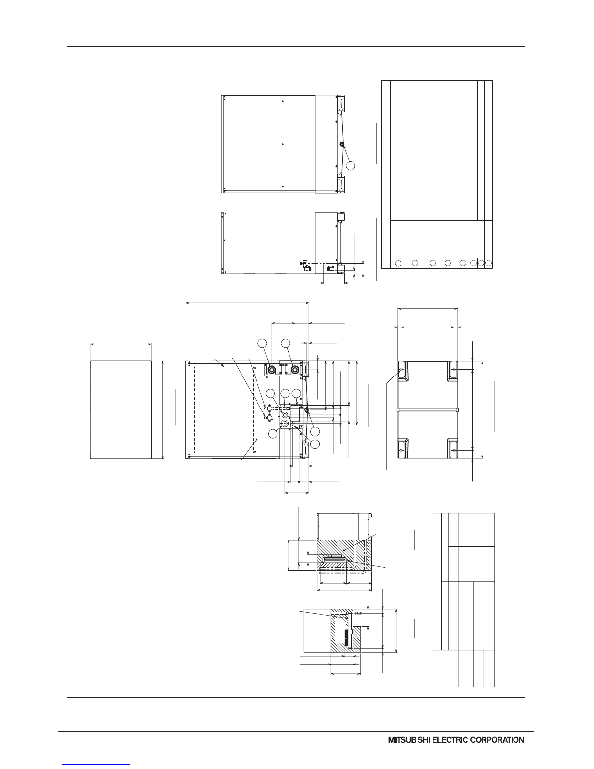
WR2-28
PQRY-P-T(S)LMU, Y(S)LMU (April 2017 Ver2)
© 2017 Mitsubishi Electric US, Inc.
2. EXTERNAL DIMENSIONS
Unit : mm(in)
<Accessories>
• Refrigerant (low pressure) conn. elbow
• • • • •
1pc.
(P72/P96/P120 ; Packaged in the accessory kit)
(P72/P96/P120 ; Packaged in the accessory kit)
• Sealing material for field piping (high pressure, low pressure)
• • • • •
1pc. each
(P72/P96/P120 ; Packaged in the accessory kit)
(P72/P96/P120 ; Packaged in the accessory kit)
• Pipe cover for low pressure
• • • • •
1pc.
(P72/P96/P120 ; Packaged in the accessory kit)
• Sealing material for drain socket
• • • • •
1pc.
• Sealing material for water stopper
• • • • •
1pc.
• Water stopper
• • • • •
1pc.
(P72/P96/P120 ; Packaged in the accessory kit)
(5/8)
(3/4)
ø19.05 Brazed
ø15.88 Brazed
Low pressureHigh pressure Low pressureHigh pressure
Diameter
PQRY-P120TLMU-A
PQRY-P96TLMU-A
PQRY-P72TLMU-A
Model
Connecting pipe specifications
(1)
ø25.4
Refrigerant pipe
Service valve
(3/4)
ø19.05
*1 *2
*2.Use the pipe joint(field supply) and connect to the refrigerant service valve piping.
*1.Connect by using the connecting pipes and elbow that are supplied.
*1 *2
(3/4)
(7/8)
ø22.2 Brazed
ø19.05 Brazed
*1
*1 *2
1100(43-5/16)
435(17-3/16)
23(15/16)
124(4-15/16) 208
394(15-9/16)
422(16-5/8)
58(2-5/16)
570(22-1/2)
185(7-5/16)
(8-1/4)
77(3-1/16)
140(5-9/16)
75(3)
83(3-5/16)
(8-9/16)
29
(1-3/16)
91
(3-5/8)
77(3-1/16)
216
145(5-3/4)
89(3-9/16)
880(34-11/16)
550(21-11/16)
721 (28-7/16)
473(470~476)
31.531.5
(1-1/4)
(18-5/8)(18-9/16~18-3/4)
(1-1/4)
(2-7/8)(2-7/8)
72.572.5
2×2-14(9/16)×31(1-1/4) Oval hole
(Mounting pitch)
(Mounting pitch)
(536)(21-1/8)
(866)(34-1/8)
Bottom view
600(23-5/8)
450(17-3/4)
163(6-7/16)
(503)
1100(43-5/16)
350(13-13/16)
(90)
700
(90)
(34-11/16)
880
450
(17-3/4)
163(6-7/16)
600(23-5/8)
(19-13/16)
(3-9/16)
(3-9/16)
(27-9/16)
(21-1/8)
536
Control box
Refrigerant service
valve <High pressure>
Refrigerant service
valve <Low pressure>
Service panel
Top view
(front side)
Service clearance
control box
The space for
replacement
control box
The space for
replacement
Top view
Front view
Right side view Back view
Fig.BFig.A
7
6
1
5
4
3
82
8
NO.
For pipes
For wires
For transmission
cables
Usage
Front through hole
Front through hole
Front through hole
Front through hole
Specifications
Rc3/4 Screw
NPT1-1/2 Screw
NPT1-1/2 Screw
inlet
outlet
Drain pipe
Water pipe
1
2
4
3
567
8
140 × 77 Knockout hole
(5-9/16) (3-1/16)
ø62.7 or ø34.5 Knockout hole
(2-1/2) (1-3/8)
ø43.7 or ø22.2 Knockout hole
(1-3/4) (7/8)
ø
45 Knockout hole
(1-13/16)
ø
34 Knockout hole
(1-3/8)
(Uses when twinning kit
(optional parts) is mounted.)
Front through hole
• Refrigerant (high pressure) conn. pipe
• • • • •
1pc.
(P72/P96/P120 ; Packaged in the accessory kit)
(front side)
Service
clearance
Note1.Seal around the water piping, the refrigerant piping, the power supply,
Note2.At the time of product shipment, the front side piping
serves as the local drainage connection.
When connecting on the rear side, please remove the
rear side plug sealing corks, and attach on the front side.
Ensure there is no leak in piping system once connected.
Note3.See Fig. A and Fig. B for service clearances.
Note4.If piping is installed in front of the unit, provide clearances
as shown in Fig. A and Fig. B.
Note5.Environmental condition for installation; -20~40°C(DB) (-4~104°F)
for indoor installation.
Note6.In case the temperature around the heat source unit has
possibility to drop under 0°C(32°F), be careful for the following
point to prevent the pipe burst by the water pipe freeze-up.
•Circulate the water all the time even if heat source unit is not in
operation and provide glycol for freeze protection.
•Drain the water from inside of the heat source unit when
the heat source unit will not operate for a long term.
Note7.Ensure that the drain piping is downward with a pitch of
more than 1/100.
Note8.At brazing of pipes, wrap the refrigerant service valve
with wet cloth and keep the temperature of
refrigerant service valve under 120°C(248°F).
and the control wiring and plug unused knockout holes with putty,
etc., to prevent moisture or dirt from entering cabinet.
Top of unit casing not suitable for supporting system
modules stacked above - field framing required for stacking
modules of additional systems
PQRY-P72, 96, 120TLMU-A
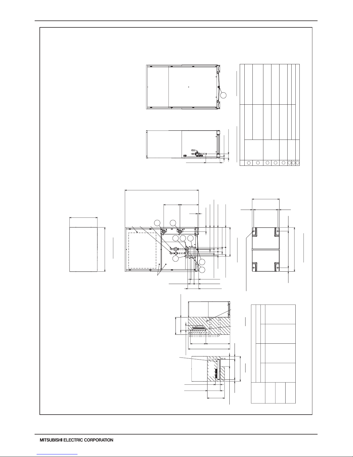
PQRY-P-T(S)LMU, Y(S)LMU (April 2017 Ver2)
WR2-29
© 2017 Mitsubishi Electric US, Inc.
2. EXTERNAL DIMENSIONS
Unit : mm(in)
(7/8)
ø22.2 Brazed
*1
2×2-14(9/16)×31(1-1/4) Oval hole
<Accessories>
•
Refrigerant (high pressure) conn. pipe • • • • • 1pc.
(
P144/P168/P192
; Packaged in the accessory kit)
(
P144/P168/P192
; Packaged in the accessory kit)
•
Sealing material for water stopper• • • • • 1pc.
(
P144/P168/P192 ; Packaged in the accessory kit)
(
P144/P168/P192
; Packaged in the accessory kit)
• Sealing material for drain socket
• • • • •
1pc.
(
P144/P168/P192 ; Packaged in the accessory kit)
•
Sealing material for field piping (high pressure, low pressure) • • • • •
1pc. each
(
P144/P168/P192
; Packaged in the accessory kit)
•
Pipe cover for low pressure • • • • • 1pc.
• Sealing material for base
leg (two types)
• • • • • 4pc. each
(
P144/P168/P192
; Packaged in the accessory kit)
(
P144/P168/P192 ; Packaged in the accessory kit)
•
Sealing material for panel• • • • • 1pc.
•
Water stopper • • • • •
1pc.
•
Refrigerant (low pressure) conn. pipe • • • • •
1pc.
(
P144/P168/P192 ; Packaged in the accessory kit)
Top view
6
7
5143
8
Front view
Control box
Service panel
Refrigerant service
valve <High pressure>
8
Right side view
Back view
Refrigerant service
valve <Low pressure>
2
Bottom view
Fig.B
control box
The space for
replacement
(front side)
Service clearance
Fig.A
Top view
control box
The space for
replacement
(1)
(1-1/8)
(1-1/8)
ø
25.4
ø28.58 Brazed ø
28.58
Refrigerant pipe Service valve
Diameter
Model
Connecting pipe specifications
Low pressure High pressure
*1
PQRY-P144TLMU-A
PQRY-P168TLMU-A
PQRY-P192TLMU-A
Low pressure High pressure
*1.Connect by using the connecting pipes that are supplied.
1450(57-1/8)
880(34-11/16)
550(21-11/16)
367
23
434(17-1/8)
82(3-1/4)
421(16-5/8)75(3)
58(2-5/16)
393(15-1/2)
140(5-9/16)
320
(12-5/8)(14-1/2)
(15/16)
29(1-3/16)
83(3-5/16)
426(16-13/16)
84(3-5/16)
278(11)
569(22-7/16)
216(8-9/16)
89(3-9/16)
77(3-1/16)
145(5-3/4)
721(28-7/16)
473(470~476)
31.531.5
72.5 72.5
(866)(34-1/8)
(2-7/8)
(Mounting pitch)
(2-7/8)
(536)(21-1/8)
(Mounting pitch)
(18-5/8)(18-9/16~18-3/4)
(1-1/4)(1-1/4)
163(6-7/16)
840(33-1/8)
536
600(23-5/8)
450(17-3/4)
1450(57-1/8)
600(23-5/8)
450(17-3/4)
163(6-7/16)
350(13-13/16)
700(27-9/16)
880(34-11/16)
(111)
(69)
(21-1/8)
(4-3/8)
(2-3/4)
NO.
For pipes
For wires
For transmission
cables
Usage
Front through hole
Front through hole
Front through hole
Front through hole
Specifications
Rc3/4 Screw
NPT1-1/2 Screw
NPT1-1/2 Screw
inlet
outlet
Drain pipe
Water pipe
1
2
4
3
567
8
140 × 77 Knockout hole
(5-9/16) (3-1/16)
ø62.7 or ø34.5 Knockout hole
(2-1/2) (1-3/8)
ø43.7 or ø22.2 Knockout hole
(1-3/4) (7/8)
ø
45 Knockout hole
(1-13/16)
ø
34 Knockout hole
(1-3/8)
(Uses when twinning kit
(optional parts) is mounted.)
Front through hole
Top of unit casing not suitable for supporting system
modules stacked above - field framing required for stacking
modules of additional systems
Note1.Seal around the water piping, the refrigerant piping, the power supply,
Note2.At the time of product shipment, the front side piping
serves as the local drainage connection.
When connecting on the rear side, please remove the
rear side plug sealing corks, and attach on the front side.
Ensure there is no leak in piping system once connected.
Note3.See Fig. A and Fig. B for service clearances.
Note4.If piping is installed in front of the unit, provide clearances
as shown in Fig. A and Fig. B.
Note5.Environmental condition for installation; -20~40°C(DB) (-4~104°F)
for indoor installation.
Note6.In case the temperature around the heat source unit has
possibility to drop under 0°C(32°F), be careful for the following
point to prevent the pipe burst by the water pipe freeze-up.
•Circulate the water all the time even if heat source unit is not in
operation and provide glycol for freeze protection.
•Drain the water from inside of the heat source unit when
the heat source unit will not operate for a long term.
Note7.Ensure that the drain piping is downward with a pitch of
more than 1/100.
Note8.At brazing of pipes, wrap the refrigerant service valve
with wet cloth and keep the temperature of
refrigerant service valve under 120°C(248°F).
and the control wiring and plug unused knockout holes with putty,
etc., to prevent moisture or dirt from entering cabinet.
(front side)
Service
clearance
PQRY-P144, 168, 192TLMU-A
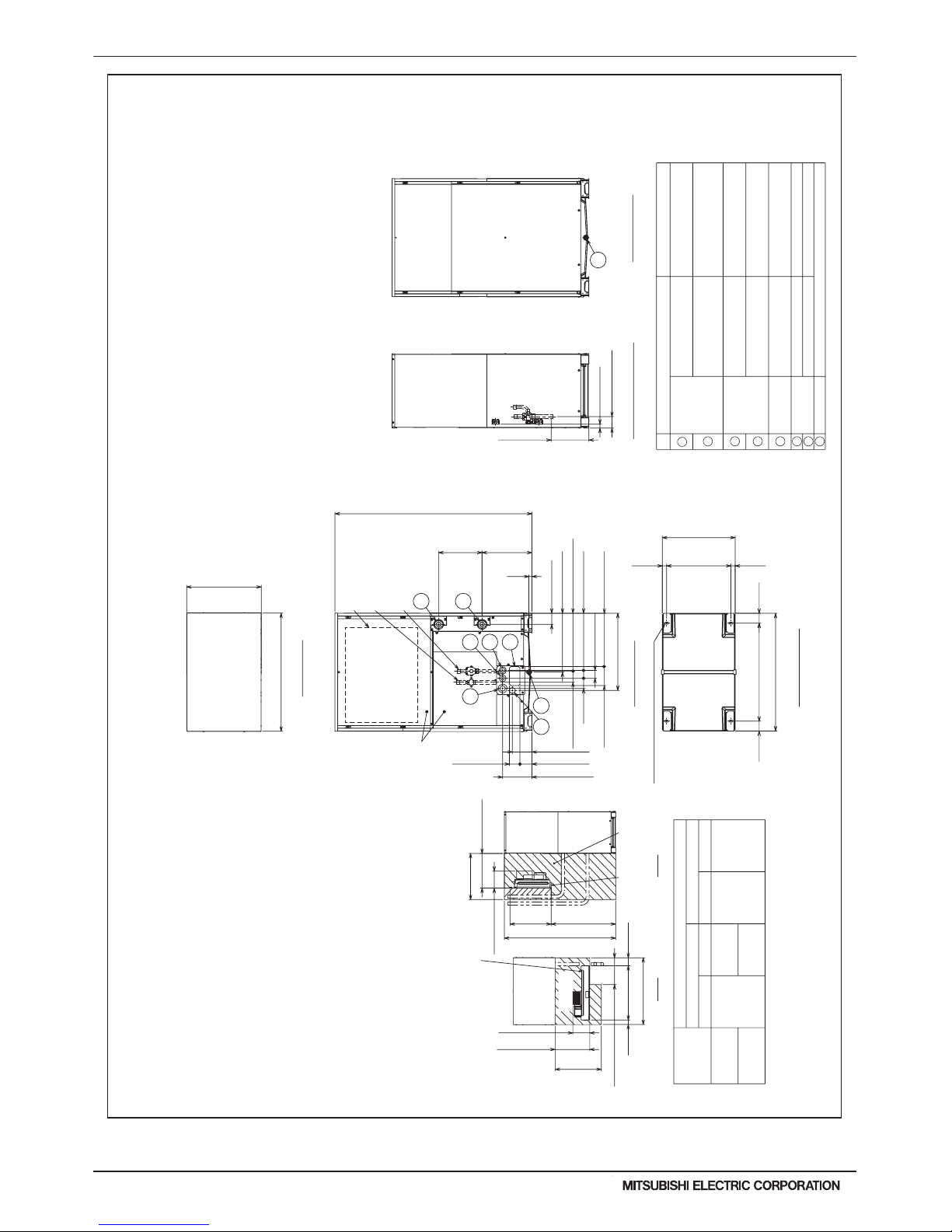
WR2-30
PQRY-P-T(S)LMU, Y(S)LMU (April 2017 Ver2)
© 2017 Mitsubishi Electric US, Inc.
2. EXTERNAL DIMENSIONS
Unit : mm(in)
(7/8)
ø22.2 Brazed
*1 *2
2×2-14(9/16)×31(1-1/4) Oval hole
<Accessories>
•
Refrigerant (high pressure) conn. pipe • • • • • 1pc.
(
P216/P240
; Packaged in the accessory kit)
(
P216/P240
; Packaged in the accessory kit)
•
Sealing material for water stopper• • • • • 1pc.
(
P216/P240
; Packaged in the accessory kit)
(
P216/P240
; Packaged in the accessory kit)
• Sealing material for drain socket
• • • • •
1pc.
(
P216/P240
; Packaged in the accessory kit)
•
Sealing material for field piping (high pressure, low pressure) • • • • • 1pc. each
(
P216/P240
; Packaged in the accessory kit)
•
Pipe cover for low pressure • • • • • 1pc.
• Sealing material for base leg (two types) • • • • • 4pc. each
(P216/P240
; Packaged in the accessory kit)
(
P216/P240
; Packaged in the accessory kit)
•
Sealing material for panel• • • • • 1pc.
•
Water stopper • • • • •
1pc.
•
Refrigerant (low pressure) conn. pipe • • • • • 1pc.
(
P216/P240
; Packaged in the accessory kit)
Top view
Front view
Right side view
Back view
Bottom view
(1)
(1-1/8)
(1-1/8)
ø
25.4
ø28.58 Brazed
ø
28.58
*1
(1-3/8)
ø34.93 Brazed
*1 *3
Connecting pipe specifications
*1.Connect by using the connecting pipes that are supplied.
*3.Use the pipe joint(field supply) and connect to the refrigerant service valve piping.
Refrigerant pipe Service valve
Diameter
Model
Low pressure High pressure Low pressure High pressure
PQRY-P216TLMU-A
PQRY-P240TLMU-A
1450(57-1/8)
880(34-11/16)
550(21-11/16)
367
23
434(17-1/8)
82(3-1/4)
421(16-5/8)
75(3)
58(2-5/16)
393(15-1/2)
140(5-9/16)
320
(12-5/8)(14-1/2)
(15/16)
29(1-3/16)
83(3-5/16)
426(16-13/16)
84(3-5/16)
278(11)
569(22-7/16)
216(8-9/16)
89(3-9/16)
77(3-1/16)
145(5-3/4)
721(28-7/16)
473(470~476)
31.5
31.5
72.5 72.5
(866)(34-1/8)
(2-7/8)
(Mounting pitch)
(2-7/8)
(536)(21-1/8)
(Mounting pitch)
(18-5/8)(18-9/16~18-3/4)
(1-1/4)
(1-1/4)
6
7
5143
8
Control box
Service panel
Refrigerant service
valve <High pressure>
8
Refrigerant service
valve <Low pressure>
2
*2.When the piping length is 65 m or longer, use the ø28.58(1-1/8) pipe for
the part that exceeds 65 m.
NO.
For pipes
For wires
For transmission
cables
Usage
Front through hole
Front through hole
Front through hole
Front through hole
Specifications
Rc3/4 Screw
NPT1-1/2 Screw
NPT1-1/2 Screw
inlet
outlet
Drain pipe
Water pipe
1
2
4
3
567
8
140 × 77 Knockout hole
(5-9/16) (3-1/16)
ø62.7 or ø34.5 Knockout hole
(2-1/2) (1-3/8)
ø43.7 or ø22.2 Knockout hole
(1-3/4) (7/8)
ø
45 Knockout hole
(1-13/16)
ø
34 Knockout hole
(1-3/8)
(Uses when twinning kit
(optional parts) is mounted.)
Front through hole
Note1.Seal around the water piping, the refrigerant piping, the power supply,
Note2.At the time of product shipment, the front side piping
serves as the local drainage connection.
When connecting on the rear side, please remove the
rear side plug sealing corks, and attach on the front side.
Ensure there is no leak in piping system once connected.
Note3.See Fig. A and Fig. B for service clearances.
Note4.If piping is installed in front of the unit, provide clearances
as shown in Fig. A and Fig. B.
Note5.Environmental condition for installation; -20~40°C(DB) (-4~104°F)
for indoor installation.
Note6.In case the temperature around the heat source unit has
possibility to drop under 0°C(32°F), be careful for the following
point to prevent the pipe burst by the water pipe freeze-up.
•Circulate the water all the time even if heat source unit is not in
operation and provide glycol for freeze protection.
•Drain the water from inside of the heat source unit when
the heat source unit will not operate for a long term.
Note7.Ensure that the drain piping is downward with a pitch of
more than 1/100.
Note8.At brazing of pipes, wrap the refrigerant service valve
with wet cloth and keep the temperature of
refrigerant service valve under 120°C(248°F).
and the control wiring and plug unused knockout holes with putty,
etc., to prevent moisture or dirt from entering cabinet.
Top of unit casing not suitable for supporting system
modules stacked above - field framing required for stacking
modules of additional systems
450(17-3/4)
840(33-1/8)
536
600(23-5/8)
1450(57-1/8)
600(23-5/8)
450(17-3/4)
350(13-13/16)
705(27-13/16)
880(34-11/16)
(108)(67)
(21-1/8)
(4-5/16)(2-11/16)
220(8-11/16)
220(8-11/16)
Fig.B
control box
The space for
replacement
(front side)
Service clearance
Fig.A
Top view
control box
The space for
replacement
(front side)
Service
clearance
PQRY-P216, 240TLMU-A
 Loading...