

Mitsubishi PM600HSA120 Datasheet
MITSUBISHI INTELLIGENT POWER MODULES
PM600HSA120
FLA T-BASE TYPE
INSULA TED PACKAGE
A
B
E E
S
E
K
H
C
N
H
M
V - DIA.
(4 TYP.)
JG
V1
FO
SR
C1
VC
C
S
P
SEE FIGURE A
FO
SR
IN
VCC
GND
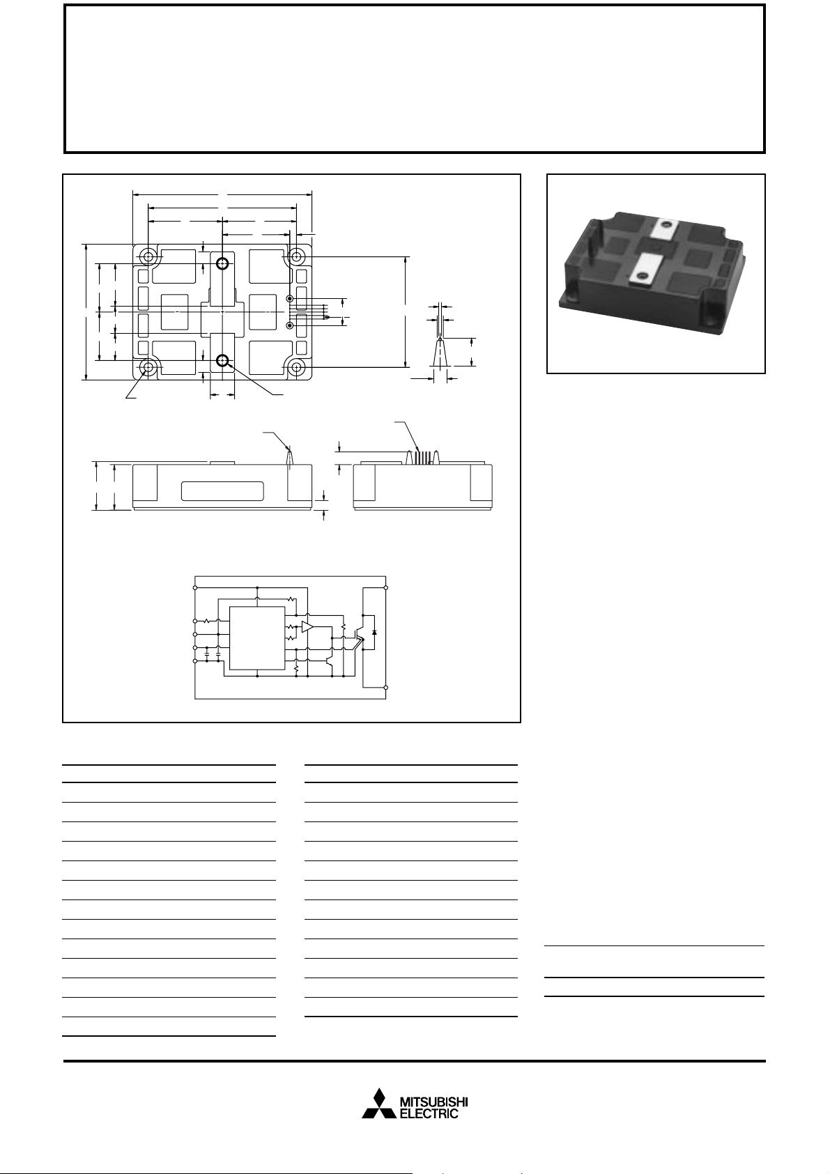
Outline Drawing and Circuit Diagram
Dimensions Inches Millimeters
A 5.24 133.0
B 4.33±0.01 110.0±0.25
C 3.98 101.0
D 3.23±0.01 82.0±0.25
E 2.16 55.0
F 1.97 50.0
G 1.42 +0.04/-0.02 36.0 +1.0/-0.5
H 1.42 36.0
J 1.33 33.7
K 1.25 31.7
L 1.02 26.0
M 0.80 20.3
N 0.79 20.0
F
W
D
C
E
TEMP
OUT1
OUT2
SENS
SINK
12345
T - M8 THD
L
Y - (4 TYP.)
0.64 MM SQ. PIN
(5 TYP.)
R
U
Dimensions Inches Millimeters
P 0.71 18.0
Q 0.59 15
R 0.53 13.5
S 0.35 9.0
T M8 Metric M8
U 0.28 7.0
V 0.26 Dia. Dia. 6.5
W 0.02 5.0
X 0.17 Dia. Dia. 4.4
Y 0.100 2.54
Z 0.15 Dia. Dia. 3.8
AA 0.06 Dia. Dia. 1.5
1.
V1
2.
SR
3.
C1
4.
VC
5.
FO
FIGURE A
AA
Z
X
- DIA.
- DIA.
Q
- DIA.
Description:
Mitsubishi Intelligent Power Modules are isolated base modules designed for power switching applications operating at frequencies to
20kHz. Built-in control circuits provide optimum gate drive and protection for the IGBT and free-wheel
diode power devices.
Features:
u Complete Output Power
Circuit
u Gate Drive Circuit
u Protection Logic
– Short Circuit
– Over Current
– Over Temperature
– Under Voltage
Applications:
u Inverters
u UPS
u Motion/Servo Control
u Power Supplies
Ordering Information:
Example: Select the complete
part number from the table below
-i.e. PM600HSA120 is a 1200V,
600 Ampere Intelligent Power Module.
Type Current Rating V
Amperes Volts (x 10)
PM 600 120
CES
Sep.1998

MITSUBISHI INTELLIGENT POWER MODULES
PM600HSA120
FLA T-BASE TYPE
INSULA TED PACKAGE
Absolute Maximum Ratings, Tj = 25°C unless otherwise specified
Ratings Symbol PM600HSA120 Units
Power Device Junction Temperature T
Storage T emperature T
Case Operating Temperature T
j
stg
C
Mounting Torque, M6 Mounting Screws — 3.92 ~ 5.88 N · m
Mounting Torque, M8 Main Terminal Screws — 8.83 ~ 10.8 N · m
Module Weight (Typical) — 1090 Grams
Supply Voltage Protected by OC and SC (VD = 13.5 - 16.5V , Inverter Part) V
Isolation Voltage (Main Terminal to Baseplate, AC 1 min.) V
CC(prot.)
iso
Control Sector
Supply Voltage (Applied between V1-VC)V
Input Voltage (Applied between C1-VC)V
Fault Output Supply Voltage (Applied between Fo-Vc)V
Fault Output Current (Fault Current of FO Terminal) I
D
CIN
FO
FO
-20 to 150 °C
-40 to 125 °C
-20 to 100 °C
800 Volts
2500 Vrms
20 Volts
10 Volts
20 Volts
20 mA
IGBT Inverter Sector
Collector-Emitter Voltage (VD = 15V, V
Collector Current, (TC = 25°C) I
Peak Collector Current, (TC = 25°C) I
Collector Dissipation P
= 5V) V
CIN
CES
C
CP
C
1200 Volts
600 Amperes
1200 Amperes
3470 Watts
Electrical and Mechanical Characteristics, Tj = 25°C unless otherwise specified
Characteristics Symbol Test Conditions Min. Typ. Max. Units
Control Sector
Over Current Trip Level Inverter Part OC -20°C ≤ Tj ≤ 125°C, VD = 15V 740 1000 — Amperes
Short Circuit Trip Level Inverter Part SC -20°C ≤ Tj ≤ 125°C, VD = 15V 1000 1400 — Amperes
Over Current Delay Time t
off(OC)
Over T emperature Protection OT Trip Level 100 110 120 °C
OT
r
Supply Circuit Under Voltage Protection UV Trip Level 11.5 12.0 12.5 Volts
UV
r
Supply Voltage V
Circuit Current I
Input ON Threshold Voltage V
Input OFF Threshold Voltage V
PWM Input Frequency f
Fault Output Current I
Minimum Fault Output Pulse Width t
SR Terminal Output Voltage V
D
th(on)
th(off)
PWM
FO(H)
I
FO(L)
FO
SR
D
VD = 15V, V
-20°C ≤ Tj ≤ 125°C, Rin = 6.8kΩ 4.5 5.1 5.6 Volts
VD = 15V — 5 — µs
Reset Level 85 95 105 °C
Reset Level — 12.5 — Volts
Applied between V1-V
= 5V , V1-V
CIN
Applied between C1-V
Applied between C1-V
C
C
C
C
13.5 15 16.5 Volts
—2330mA
1.2 1.5 1.8 Volts
1.7 2.0 2.3 Volts
3-φ Sinusoidal — 15 20 kHz
VD = 15V , VFO = 15V — — 0.01 mA
VD = 15V , VFO = 15V — 10 15 mA
VD = 15V 1.0 1.8 — ms
Sep.1998
 Loading...