

Mitsubishi PM50CTK060 Datasheet
PM50CTK060
MITSUBISHI INTELLIGENT POWER MODULES
PM50CTK060
FLAT-BASE TYPE
INSULATED PACKAGE
¡600V, 50A Current-sense 6kHz IGBT
type inverter
¡Built in IGBT gate drive circuit
Built in Faule OC, SC, OT & UV protection
¡
Fault output
¡3.7kW class inverter application
APPLICATION
Air conditioner, mortor control
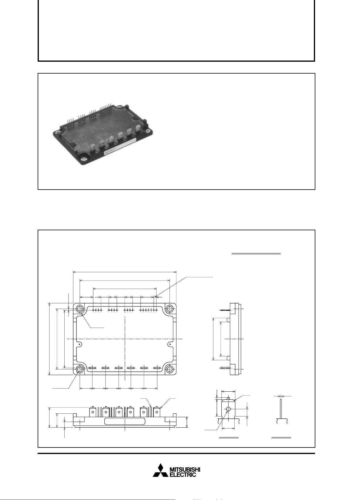
OUTLINE DRAWING Dimensions in mm
A · B: TERMINAL NAME
±1
70
±0.8
58.5
±0.5
56.5
0.75
100.5
±1
88.5
±0.5
60.96
±0.8
(13.77)
7.62 7.62 7.62
14325876
4 - R5
20 21 22 23 24 25
121110 13 161514 17 1918
9
15 - 2.54
±0.25
1.
V
2.
NC
3.
U
4.
V
5.
V
6.
NC
7.
V
8.
V
9.
V
33
41
UPC
P
UP1
VPC
P
VP1
WPC
10.
11.
12.
13.
14.
15.
16.
17.
18.
NC
W
V
V
V
NC
U
V
W
P
WP1
NC
N1
N
N
N
19.
20.
21.
22.
23.
24.
25.
F
P
NC
N
U
V
W
O
±1
19
4 - φ4.5
13.5
5.5
(13)
12.5
±0.25
12.5
±0.25
12.5
±0.25
LABEL
12.5
±0.25
12.5
±0.25
B A
10
φ1.65
(1)
7.95
6.35
6
C1
3.4
(t = 0.8)
0.6
(t = 0.4)
B: DETAILA: DETAIL
Aug.1999
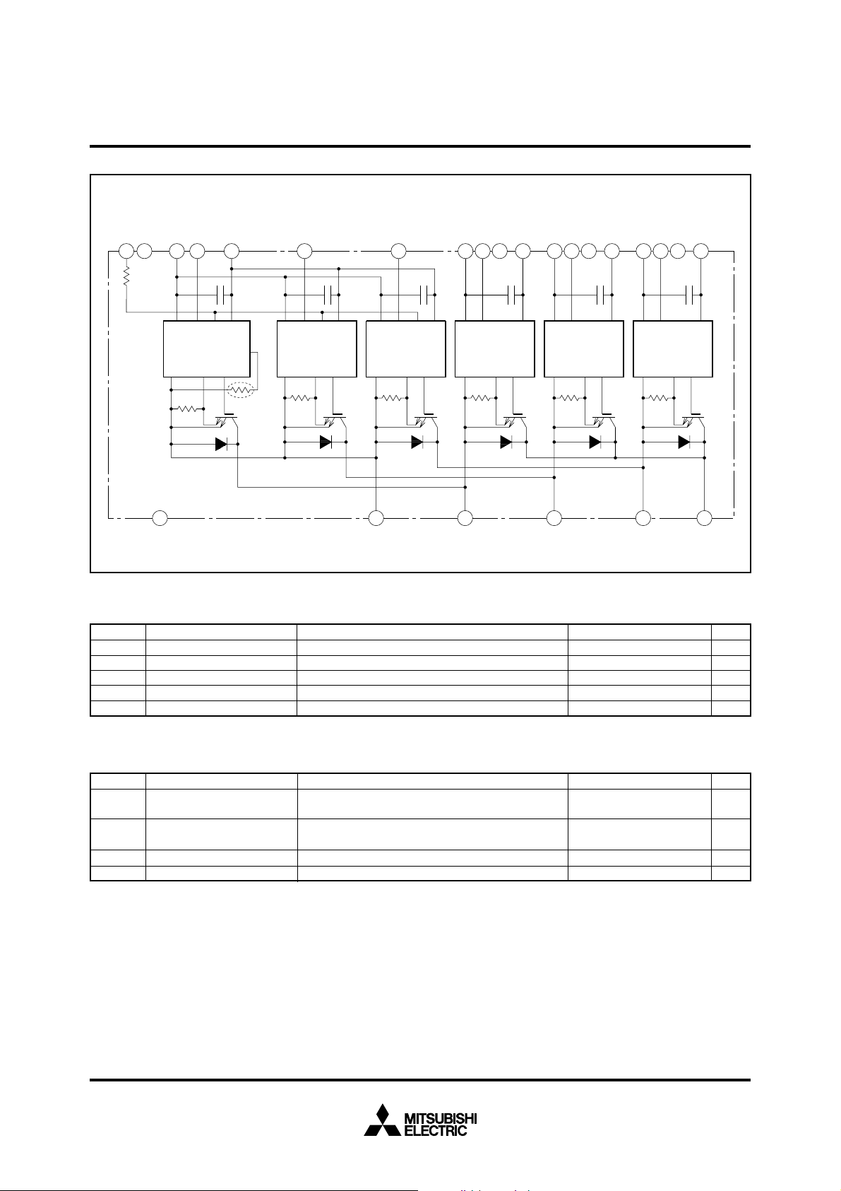
EQUIVALENT CIRCUIT DIAGRAM
MITSUBISHI INTELLIGNET POWER MODULES
PM50CTK060
FLA T-BASE TYPE
INSULATED PACKAGE
FONC VNCW
15 13
19
R
fo
GND
N
V
N1
14 17 16 9 11 12 7 1
18
In FOV
CC
GND
V
N
In FOV
CC
TEMP
GND Si Out
GND Si Out
Th
21 22 25 24 23 20
MAXIMUM RATINGS (Tj = 25°C, unless otherwise noted)
INVERTER PART
Symbol Parameter
VCES
±IC
±ICP
PC
Tj
Collector-emitter voltage
Collector current
Collector current (peak)
Collector dissipation
Junction temperature
D = 15V, ICIN = 10mA
V
C = 25°C
T
C = 25°C
T
C = 25°C
T
U
N
GND
In FOVCCGND
GND Si Out
Conditions
V
WPC
WPV
WP1
NC NC NC
V
VPC
VPV
VP1
10 5 6 8 3 2 4
In VCCGND
GND Si Out
In VCCGND
GND Si Out
UPV
In V
UP1
CC
V
UPC
GND Si Out
PUVWNNC
Ratings Unit
600
50
100
100
–20 ~ +150
V
A
A
W
°C
CONTROL PART
Symbol
V
CIN
I
VFO
IFO
D
Supply voltage
Input current
Fault output supply voltage
Fault output current
Parameter Unit
Applied between : V
Conditions
UP1-VUPC, VVP1-VVPC
VWP1-VWPC, VN1-VNC
Applied between : UP-VUPC, VP-VVPC, WP-VWPC,
N · VN · WN-VNC
U
Applied between : FO-VNC
Sink current of FO terminal
Ratings
20 V
20
20
mA20
V
mA
Aug.1999
 Loading...