

Mitsubishi PM25RSK120 Datasheet
MITSUBISHI INTELLIGENT POWER MODULES
PM25RSK120
FLA T-BASE TYPE
INSULA TED P ACKAGE
B
D
JAA
214365789 1210 11 13 1614 15 17 18 19
R"Y"
(4 PLACES)
A EZF G H
W
TYP
20 21 22 23 24 25
"T" (4 TYP)
M P
C
Q
o
R
F
BV
19
15
Rfo
I
N
GND F
GNDVS OUT
NCWNVN1
131814
I
O
I
N
GND F
CC
B
O
V
N
V
17
I
N
GND F
O
CC
V
CC
TEMP
OUTGNDISSGNDIOUT
TH
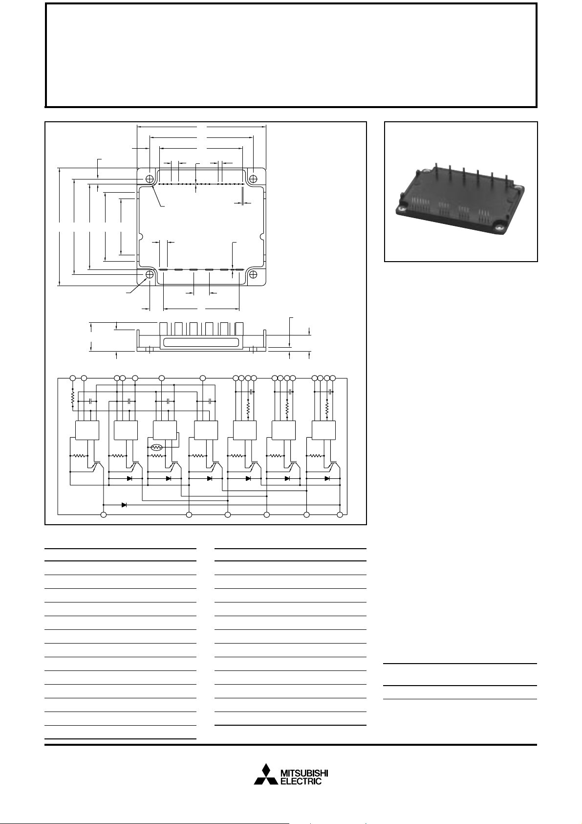
Outline Drawing and Circuit Diagram
Dimensions Inches Millimeters
A 2.76±0.04 70.0±1.0
B 3.96±0.04 100.5±1.0
C 0.71±0.04 18.0±1.0
D 3.48±0.02 88.5±0.5
E 2.30±0.02 58.5±0.5
F 2.23±0.03 56.75±0.8
G 1.61 41.0
H 1.30 33.0
J 2.70±0.03 68.58±0.8
K 0.40 10.16
L 0.10±0.01 2.54±0.25
M 0.41 10.5
N 0.53±0.01 13.5±0.3
TYP
K
N
TYP
U
GND
GND S OUT OUTGND S
NW V
TYP
V
TYP
L
U
1 V
2 U
3 U
4 V
5 V
6 V
7 V
8 V
9 V
UPC
FO
P
UP1
VPC
FO
P
VP1
WPC
10 WFO
11 W
X
12 V
P
WP1
13 VNC
R
S
P
W
V
FO
W
WPC
V
N
16
N
I
O
F
CC
V
I
10
9
11
N
I
GND
O
F
I
P
V
VPC
V
V
FO
V
576
I
N
GND
F
GND S OUT
I
O
WP1
12
CC
V
P
U
VP1
UPC
V
8
V
CC
U
132
I
N
GND
GND OUT
UP
Dimensions Inches Millimeters
P 2.66±0.03 67.5±0.8
Q 0.49 12.4
R 0.17 Rad. 4.4 Rad.
S 0.35 8.9
T 0.18 Dia. Dia. 4.5
U 0.02 0.4
V 0.02±0.004 0.6 ±0.1
W 0.08±0.004 2.0±0.1
X 0.02 0.5
Y 0.20 5.0
Z 0.04 1.02
AA 0.39 9.96
14 VN1
15 BM
16 UN
17 V
18 W
19 FO
20 P
21 B
22 N
23 U
24 V
25 W
UP1
V
FO
4
F
O
CC
V
S
I
N
N
R
Description:
Mitsubishi Intelligent Power Modules are isolated base modules designed for power switching applications operating at frequencies to
20kHz. Built-in control circuits provide optimum gate drive and protection for the IGBT and free-wheel
diode power devices.
Features:
u Complete Output Power
Circuit
u Gate Drive Circuit
u Protection Logic
– Short Circuit
– Over Current
– Over T emperature
– Under Voltage
Applications:
u Inverters
u UPS
u Motion/Servo Control
u Power Supplies
Ordering Information:
Example: Select the complete
part number from the table below
-i.e. PM25RSK120 is a 1200V,
25 Ampere Intelligent Power Module.
Type Current Rating V
Amperes Volts (x 10)
PM 25 120
CES
Sep.1998

MITSUBISHI INTELLIGENT POWER MODULES
PM25RSK120
FLA T-BASE TYPE
INSULA TED PACKAGE
Absolute Maximum Ratings, Tj = 25 °C unless otherwise specified
Ratings Symbol PM25RSK120 Units
Junction T emperature T
Storage T emperature T
Case Operating Temperature T
j
stg
C
Mounting Torque M4 Mounting Screws – 0.98 ~ 1.47 N · m
Module Weight (Typical) – 130 Grams
Supply Voltage Protected by OC and SC (VD = 13.5 ~ 16.5V, Inverter Part, Tj = 125°C) V
Isolation Voltage (Main Terminal to Baseplate, AC 1 min.) V
CC(prot.)
iso
Control Sector
Supply Voltage (Applied between V
Input Voltage (Applied between UP-V
Fault Output Supply Voltage (
UP1-VUPC
UPC
Applied between UFO-V
Fault Output Current (Sink Current at UFO, VFO, WFO and FO T erminal) I
, VP-V
, V
VP1-VVPC
VPC
, WP-V
UPC
, V
WP1-VWPC
, UN · VN · WN · Br-VNC)V
WPC
, VFO-V
VPC
, VN1-VNC)V
, WFO-V
WPC
D
CIN
, FO-VNC)V
FO
FO
–20 to 150 °C
–40 to 125 °C
–20 to 100 °C
800 Volts
2500 Vrms
20 Volts
20 Volts
20 Volts
20 mA
IGBT Inverter Sector
Collector-Emitter Voltage (VD = 15V, V
Collector Current, (TC = 25°C) I
Peak Collector Current, (TC = 25°C) I
Supply Voltage (Applied between P-N) V
Supply Voltage, Surge (Applied between P-N) V
Collector Dissipation P
= 15V) V
CIN
CC (surge)
Brake Sector
Collector-Emitter Voltage (VD = 15V, V
Collector Current, (TC = 25°C) I
Peak Collector Current, (TC = 25°C) I
Supply Voltage (Applied between P-N) V
Supply Voltage, Surge (Applied between P-N) V
Collector Dissipation P
Diode Forward Current I
Diode DC Reverse Voltage V
= 15V) V
CIN
CC (surge)
CES
C
CP
CC
C
CES
C
CP
CC
C
F
R(DC)
1200 Volts
25 Amperes
50 Amperes
900 Volts
1000 Volts
100 Watts
1200 Volts
10 Amperes
20 Amperes
900 Volts
1000 Volts
43 Watts
10 Amperes
1200 Volts
Sep.1998
 Loading...