

Mitsubishi PM200DSA120 Datasheet
MITSUBISHI INTELLIGENT POWER MODULES
PM200DSA120
FLA T-BASE TYPE
INSULA TED PACKAGE
A
B
C2E1 E2 C1
C
D
E
HH
21345
2345
1
J
Q
S - DIA.
(4 TYP.)
N
J
P
N SIDE P SIDE
1.
2.
3.
4.
5.
VN1
SNR
CN1
VNC
FNO
1.
VP1
2.
SPR
3.
CP1
4.
VPC
5.
FPO
N - DIA.
(4 TYP.)
P - M6 THD.
(3 TYP.)
F
G
VP1
FPO
SPR
CP1
VPC
VN1
FNO
SNR
CN1
VNC
K
FO
SR
IN
FO
SR
IN
R (8 TYP.)
VCC
GND
VCC
GND
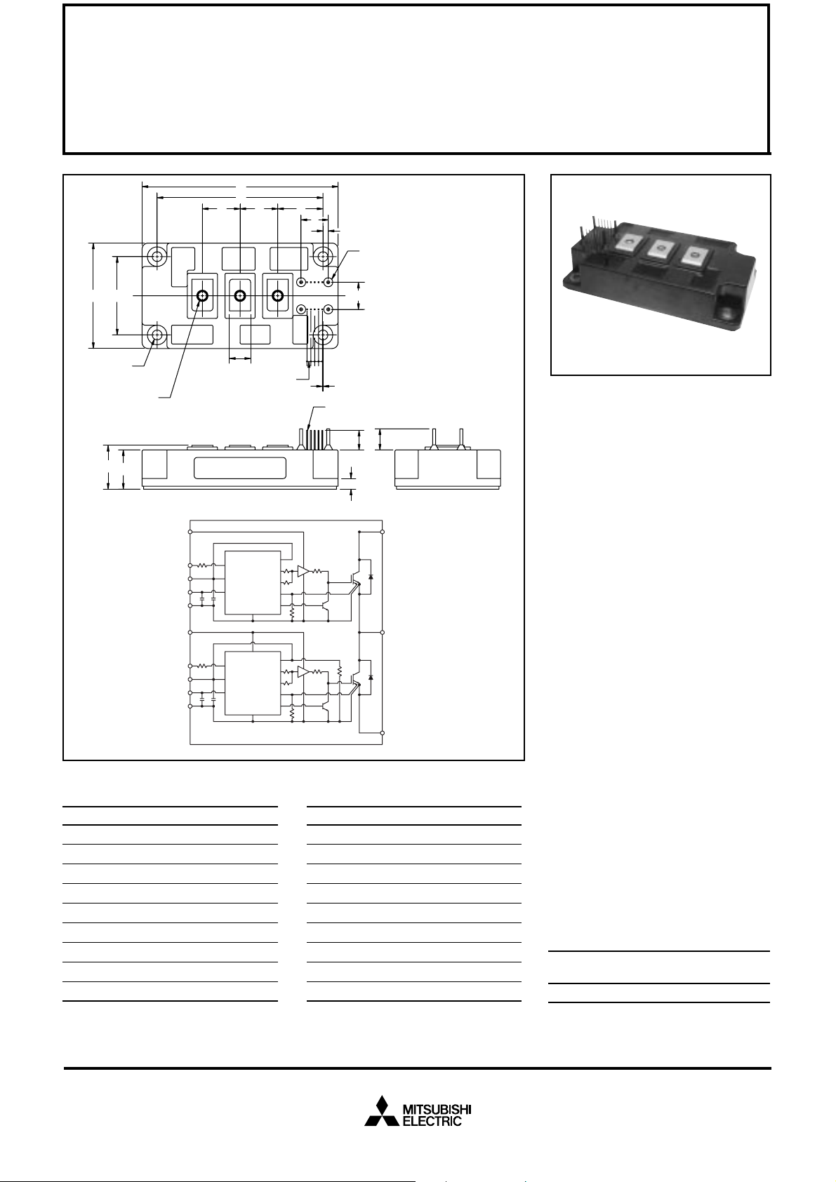
Outline Drawing and Circuit Diagram
Dimensions Inches Millimeters
A 5.12 130.0
B 4.33±0.010 110.0±0.25
C 2.76 70.0
D 2.05±0.010 52.0±0.25
E 1.18 30.0
F 1.14 +0.04/-0.02 29.0 +1/-0.5
G 1.02 26.0
H 0.98 25.0
J 0.71 18.0
TEMP
OUT1
OUT2
SENS
SINK
TEMP
OUT1
OUT2
SENS
SINK
T
0.64 MM SQ. PIN
(10 TYP.)
K
L
M
C1
C2E1
E2
Dimensions Inches Millimeters
K 0.55 14.0
L 0.51 13.0
M 0.28 7.0
N 0.26 Dia. Dia. 6.5
P M6 Metric M6
Q 0.14 3.5
R 0.100 2.54
S 0.08 Dia. Dia. 2.0
T 0.016 0.42
Description:
Mitsubishi Intelligent Power Modules are isolated base modules designed for power switching applications operating at frequencies to
20kHz. Built-in control circuits provide optimum gate drive and protection for the IGBT and free-wheel
diode power devices.
Features:
u Complete Output Power
Circuit
u Gate Drive Circuit
u Protection Logic
– Short Circuit
– Over Current
– Over Temperature
– Under Voltage
Applications:
u Inverters
u UPS
u Motion/Servo Control
u Power Supplies
Ordering Information:
Example: Select the complete
part number from the table below
-i.e. PM200DSA120 is a 1200V,
200 Ampere Intelligent Power Module.
Type Current Rating V
Amperes Volts (x 10)
PM 200 120
CES
Sep.1998

MITSUBISHI INTELLIGENT POWER MODULES
PM200DSA120
FLA T-BASE TYPE
INSULA TED PACKAGE
Absolute Maximum Ratings, Tj = 25°C unless otherwise specified
Ratings Symbol PM200DSA120 Units
Power Device Junction Temperature T
Storage T emperature T
Case Operating Temperature T
Mounting Torque, M6 Mounting Screws — 3.92~5.88 N · m
Mounting Torque, M6 Main Terminal Screws — 3.92~5.88 N · m
Module Weight (Typical) — 630 Grams
Supply Voltage Protected by OC and SC (VD = 13.5 - 16.5V, Inverter Part) V
Isolation Voltage (Main Terminal to Baseplate, AC 1 min.) V
j
stg
C
CC(prot.)
iso
Control Sector
-20 to 150 °C
-40 to 125 °C
-20 to 100 °C
800 Volts
2500 Vrms
Supply Voltage (Applied between VP1-VPC, VN1-VNC)V
Input Voltage (Applied between CP1-VPC, CN1-VNC)V
Fault Output Supply Voltage (Applied between Fpo-Vpc and Fno-Vnc)VFO20 Volts
Fault Output Current (Sink Current at FPO, FNO Terminal) I
D
CIN
FO
20 Volts
10 Volts
20 mA
IGBT Inverter Sector
Collector-Emitter Voltage (VD = 15V, V
Collector Current, (Tc = 25°C) I
Peak Collector Current, (Tc = 25°C) I
Supply Voltage (Applied between C1 - E2) V
Supply Voltage, Surge (Applied between C1 - E2) V
Collector Dissipation P
= 5V) V
CIN
CES
C
CP
CC
CC(surge)
C
1200 Volts
200 Amperes
400 Amperes
900 Volts
1000 Volts
1140 Watts
Sep.1998
 Loading...