

Mitsubishi PM15RSH120 Datasheet
MITSUBISHI INTELLIGENT POWER MODULES
PM15RSH120
FLA T-BASE TYPE
INSULA TED P ACKAGE
A
B
C
D
P
P
10
U (4 TYP.)
MMMM
E
N
NI
VVW
V
CC
O
CC
V
IN
V
F
TEMP
SIGND GND
OUT
OUT
P
12 14 16 18
V
Z
2.0 ± 0.1 X 0.5 ± 0.1 MM PIN
(6 TYP.)
0.6 ± 0.1 X 0.4 ± 0.1 MM PIN
(19 TYP.)
L
R
N
U
O
IN
F
SIGND GND
FO
VPC
WPI
WPC
V
CC
V
OUT
VFOV
VP
W
WP
CC
O
IN
V
IN
F
SIGND GND
OUT
V
UPC
1.
2.
U
FO
3.
PN
V
4.
UPI
5.
V
VPC
6.
V
FO
V
7.
P
V
8.
GH
VPI
9.
V
WPC
10.
W
W
11.
V
12.
WPI
V
13.
NC
14.
15.
16.UU
17.
18.
19.
20.
21.
22.
23.
FO
P
24.
25.W
V
NI
B
R
V
N
W
N
F
O
P
B
N
U
V
Description:
Mitsubishi Intelligent Power Modules are isolated base modules designed for power switching applica-
J
W
K
tions operating at frequencies to
20kHz. Built-in control circuits provide optimum gate drive and protection for the IGBT and free-wheel
diode power devices.
VPI
V
V
V
V
UFOUP
Features:
UPI
UPC
u Complete Output Power
Circuit
CC
O
V
F
SIGND GND
OUT
CC
V
FOIN
SIGND GND
OUT
u Gate Drive Circuit
u Protection Logic
– Short Circuit
– Over Current
– Over T emperature
PUVWN
– Under Voltage
Y (15 TYP.)
F
V - DIA.
(4 TYP.)
X
S
Q
T
12W34 75 6 8 9 11 13 15 17 19
PBNU
NM
AA
N
NC
R
O
F
B
O
CC
O
IN
V
IN
F
SIGND GND
F
SIGND GND
OUT
B
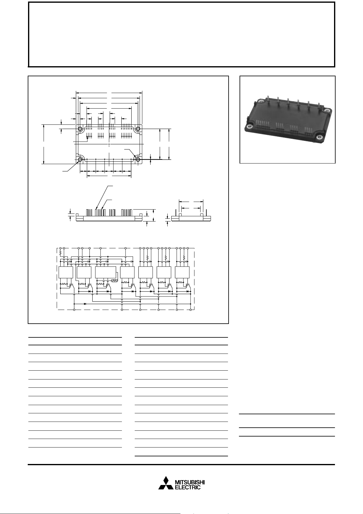
Outline Drawing and Circuit Diagram
Dimensions Inches Millimeters
A 3.98±0.04 101.0±1.0
B 3.78 96.0
C 3.48±0.03 88.5±0.8
D 2.700±0.03 68.58±0.8
E 2.66±0.02 67.5±0.5
F 2.36±0.04 60.0±1.0
G 1.85±0.02 47.0±0.5
H 1.83±0.03 46.5±0.8
J 1.28 32.6
K 0.97 24.6
L 0.71±0.04 18.0±1.0
M 0.53±0.01 13.5±0.3
Dimensions Inches Millimeters
N 0.41 10.5
P 0.400 10.16
Q 0.392 9.96
R 0.31 8.0
S 0.26 6.5
T 0.246 6.25
U 0.18 Rad. Rad. 4.5
V 0.18 Dia. Dia. 4.5
W 0.17±0.02 4.4±0.5
X 0.10 2.5
Y 0.100±0.01 2.54±0.25
Z 0.02 0.5
AA 0.14 3.5
Applications:
u Inverters
u UPS
u Motion/Servo Control
u Power Supplies
Ordering Information:
Example: Select the complete
part number from the table below
-i.e. PM15RSH120 is a 1200V,
15 Ampere Intelligent Power Module.
Type Current Rating V
Amperes Volts (x 10)
PM 15 120
CES
Sep.1998

MITSUBISHI INTELLIGENT POWER MODULES
PM15RSH120
FLA T-BASE TYPE
INSULA TED PACKAGE
Absolute Maximum Ratings, Tj = 25°C unless otherwise specified
Ratings Symbol PM15RSH120 Units
Power Device Junction Temperature T
Storage T emperature T
Case Operating Temperature T
j
stg
C
Mounting Torque, M4 Mounting Screws — 0.98 ~ 1.47 N · m
Module Weight (Typical) — 100 Grams
Supply Voltage Protected by OC and SC (VD = 13.5 - 16.5V , Inverter Part, Tj = 125°C) V
Isolation Voltage (Main Terminal to Baseplate, AC 1 min.) V
CC(prot.)
iso
Control Sector
Supply Voltage (Applied between V
UP1-VUPC
Input Voltage (Applied between UP-V
Fault Output Supply Voltage Applied between (
Fault Output Current (Sink Current at UFO, VFO, WFO and FO Terminal) I
UPC
, VP-V
, V
VP1-VVPC
VPC
UFO-V
, WP-V
UPC
, V
WP1-VWPC
, UN · VN · WN · Br-VNC)V
WPC
, VFO-V
VPC
, VN1-VNC)V
, WFO-V
WPC
CIN
, FO-VNC)V
FO
FO
D
-20 to 150 °C
-40 to 125 °C
-20 to 100 °C
800 Volts
2500 Vrms
20 Volts
20 Volts
20 Volts
20 mA
IGBT Inverter Sector
Collector-Emitter Voltage (VD = 15V, V
Collector Current, (TC = 25°C) I
Peak Collector Current, (TC = 25°C) I
Supply Voltage (Applied between P - N) V
Supply Voltage, Surge (Applied between P - N) V
Collector Dissipation P
= 15V) V
CIN
CC(surge)
Brake Sector
Collector-Emitter Voltage V
Collector Current, (TC = 25°C) I
Peak Collector Current, (TC = 25°C) I
Supply Voltage (Applied between P - N) V
Supply Voltage, Surge (Applied between P - N) V
Collector Dissipation P
Diode Forward Current I
Diode DC Reverse Voltage V
CC(surge)
CES
C
CP
CC
C
CES
C
CP
CC
C
F
R(DC)
1200 Volts
15 Amperes
30 Amperes
900 Volts
1000 Volts
83 Watts
1200 Volts
10 Amperes
20 Amperes
900 Volts
1000 Volts
41 Watts
10 Amperes
1200 Volts
Sep.1998

MITSUBISHI INTELLIGENT POWER MODULES
PM15RSH120
FLA T-BASE TYPE
INSULA TED PACKAGE
Electrical and Mechanical Characteristics, Tj = 25°C unless otherwise specified
Characteristics Symbol Test Conditions Min. Ty p. Max. Units
Control Sector
Over Current Trip Level Inverter Part OC -20°C ≤ T ≤ 125°C, VD = 15V 22 37 — Amperes
Over Current Trip Level Brake Part 15 27 — Amperes
Short Circuit Trip Level Inverter Part SC -20°C ≤ T ≤ 125°C, VD = 15V — 56 — Amperes
Short Circuit Trip Level Brake Part — 41 — Amperes
Over Current Delay Time t
off(OC)
Over T emperature Protection OT Trip Level 100 110 120 °C
OT
r
Supply Circuit Under Voltage Protection UV Trip Level 11.5 12.0 12.5 Volts
UV
r
Supply Voltage V
Circuit Current I
Input ON Threshold Voltage V
Input OFF Threshold V oltage V
PWM Input Frequency f
Fault Output Current I
PWM
FO(H)
I
FO(L)
Minimum Fault Output Pulse Width t
D
D
th(on)
th(off)
FO
Applied between V
V
VP1-VVPC
VD = 15V, V
V
= 15V, V
D
UP-V
VD = 15V — 10 — µs
Reset Level — 90 — °C
Reset Level — 12.5 — Volts
, 13.5 15 16.5 Volts
, VN1-V
NC
NC
XP1-VXPC
—2535mA
— 7 10 mA
, V
WP1-VWPC
= 15V, VN1-V
CIN
= 15V , V
CIN
UP1-VUPC
Applied between 1.2 1.5 1.8 Volts
, VP-V
UPC
UN · VN · WN · Br-V
VPC
, WP-V
, 1.7 2.0 2.3 Volts
WPC
NC
3-φ Sinusoidal — 15 20 kHz
VD = 15V, VFO = 15V — — 0.01 mA
VD = 15V, VFO = 15V — 10 15 mA
VD = 15V 1.0 1.8 — ms
Sep.1998
 Loading...