

Page 1

1
Indoor units / Cassette ceiling / 2-way flow /
PLFY-P-VLMD-B
Cassette ceiling(2-way flow) PLFY-P-VLMD-B
CONTENTS
1. Specifications
2. Capacity Tables
2-1 Cooling Capacity(PUMY)
2-2 Heating Capacity(PUMY)
2-3 Cooling Capacity(Y, R2)
2-4 Heating Capacity(Y, R2)
2-5 Cooling Capacity(Big Y, Super Y, Big R2)
2-6 Heating Capacity(Big Y, Super Y, Big R2)
2-7 Cooling Capacity(WR2)
2-8 Heating Capacity(WR2)
2-9 Cooling Capacity(PU(H)Y-TM-C)
2-10 Heating Capacity(PU(H)Y-TM-C)
3. Sound Levels
3-1 Noise levels
3-2 N/C curves
3-3 OA Intake-static pressure curve
3-4 Branch duct Intake-static pressure curve
···································································
·······························································
···············································
···············································
·················································
·················································
··················································
··················································
····································
·······························································
································································
·····································································
····································
·······················
·······················
·································
····
····
·······················
2
3
3
4
5
6
7
8
9
10
11
12
13
13
13
14
15
4. External Dimensions
5. Electrical Wiring Diagram
······················································
··············································
6. Temperature/Airflow distribution
7. Options
··············································································
··································
16
18
19
20
Page 2
2
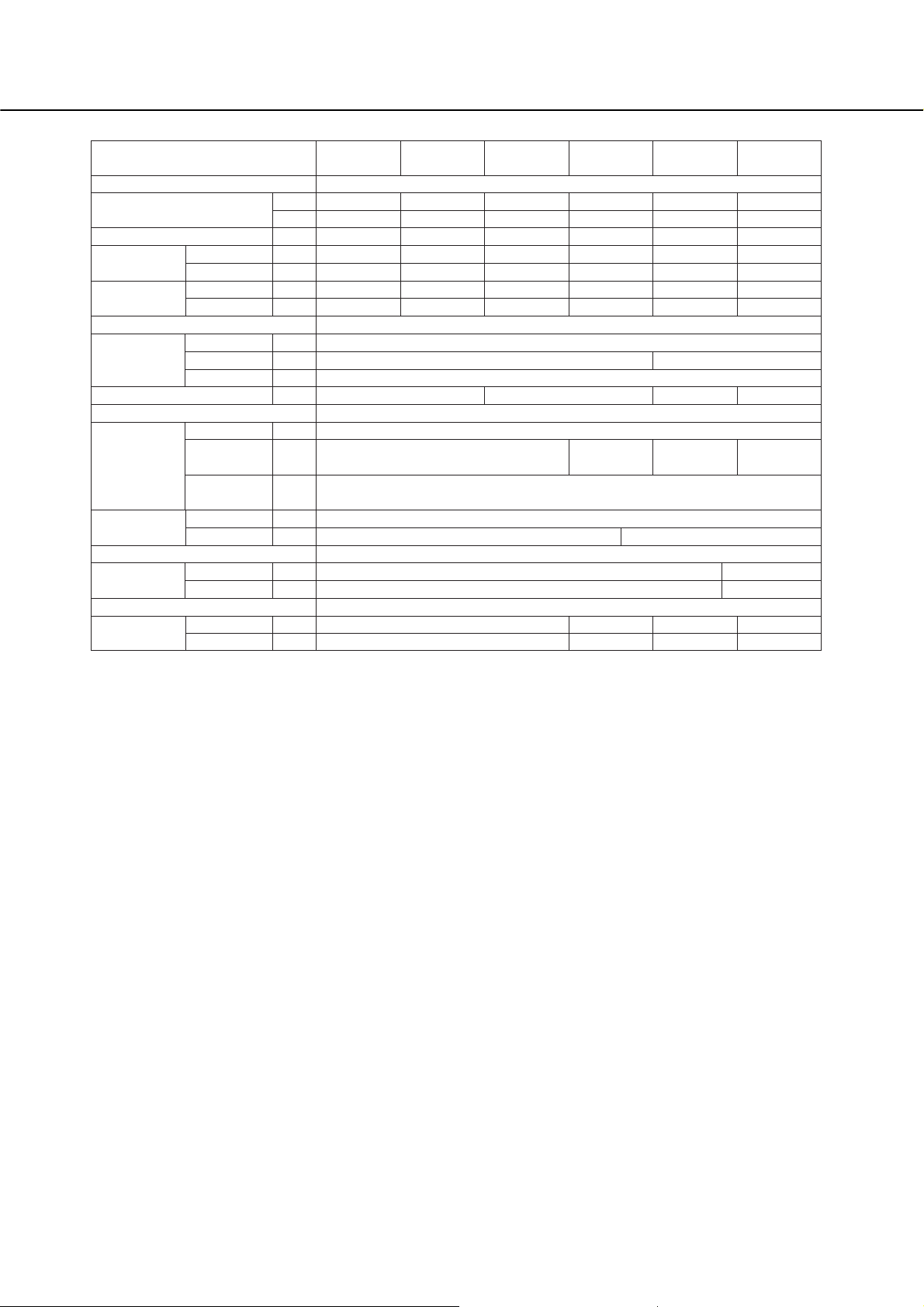
1. Specifications
Power source
Cooling capacity
Heating capacity
Power
consumption
Current
External finish(Munsel No.)
Dimension ❇3
Net weight
Heat exchanger
Fan
Motor
Air filter
Refrigerant
pipe dimension
Drain pipe dimension
Noise level
(Lo-Mid-Hi) ❇4
3
❇
Heating
Cooling
Heating
Height
Width
Depth
Type
Airflow rate
(Lo-Mid-Hi)
External static
pressure
Type
Output
Gas(Flare)
Liquid(Flare)
220V,240V
230V
kW
1
❇
kcal/h
2
❇
❇
1kW
kWCooling
kW
A
A
mm
mm
mm
kg
3
m
/min
Pa
kW
mm
mm
dB(A)
dB(A)
PLFY-
P20VLMD-B
PLFY-
P25VLMD-B
PLFY-
P32VLMD-B
PLFY-
P40VLMD-B
PLFY-
P50VLMD-B
PLFY-
P63VLMD-B
~ 220-240V 50Hz / ~ 220-230V 60Hz
2.2
2,000
2.5
0.072 / 0.075
0.065 / 0.069
0.36 / 0.37
0.30 / 0.32
Unit: Galvanizing Decoration Panel: ABS (0.7Y 8.59/0.97) Service Panel: Galvanizing (0.7Y 8.59/0.97)
23 <6.5>
2.8
2,500
3.2
0.072 / 0.075
0.065 / 0.069
0.36 / 0.37
0.30 / 0.32
6.5 - 8.0 - 9.5
0.015 0.020
27 - 30 - 33 29 - 33 - 36 31 - 34 - 37 32 - 37 - 39
28 - 31 - 34 30 - 34 - 37 32 - 35 - 38 33 - 38 - 40
3.6
3,150
4.0
0.072 / 0.075
0.065 / 0.069
0.36 / 0.37
0.30 / 0.32
290 <20>
634 <710>
24 <6.5> 28 <7.5>
Cross fin
Turbo fan x 1
Single phase induction motor
PP honeycomb fabric (long life filter)
12.7
ø
6.35
ø
VP-25
4.5
4,000
5.0
0.081 / 0.085
0.074 / 0.079
0.40 / 0.42
0.34 / 0.37
7.0 - 8.5 - 10.5 9.0 - 11.0 - 12.5 10.0 - 13.0 - 15.5
0
5.6
5,000
6.3
0.082 / 0.086
0.075 / 0.080
0.41 / 0.43
0.35 / 0.38
946 <1250> 776 <1080>
27 <7.5>
7.1
6,300
8.0
0.101 / 0.105
0.094 / 0.099
0.49 / 0.51
0.43 / 0.46
15.88
ø
9.52
ø
Note: ❇1 Cooling/Heating capacity indicates the maximum value at operation under the following condition.
Cooling: Indoor 27˚CDB/19˚CWB, Outdoor 35˚CDB
Heating: Indoor 20˚CDB, Outdoor 7˚CDB/6˚CWB
❇2 Cooling capacity indicates the maximum value at operation under the following condition.
Cooling: Indoor 27˚CDB/19.5˚CWB, Outdoor 35˚CDB (WR2: water 30˚C)
❇3 The figure in < > indicates panel's.
❇4 It is measured in anechoic room.
Page 3
3
Indoor units / Cassette ceiling / 2-way flow /
PLFY-P-VLMD-B
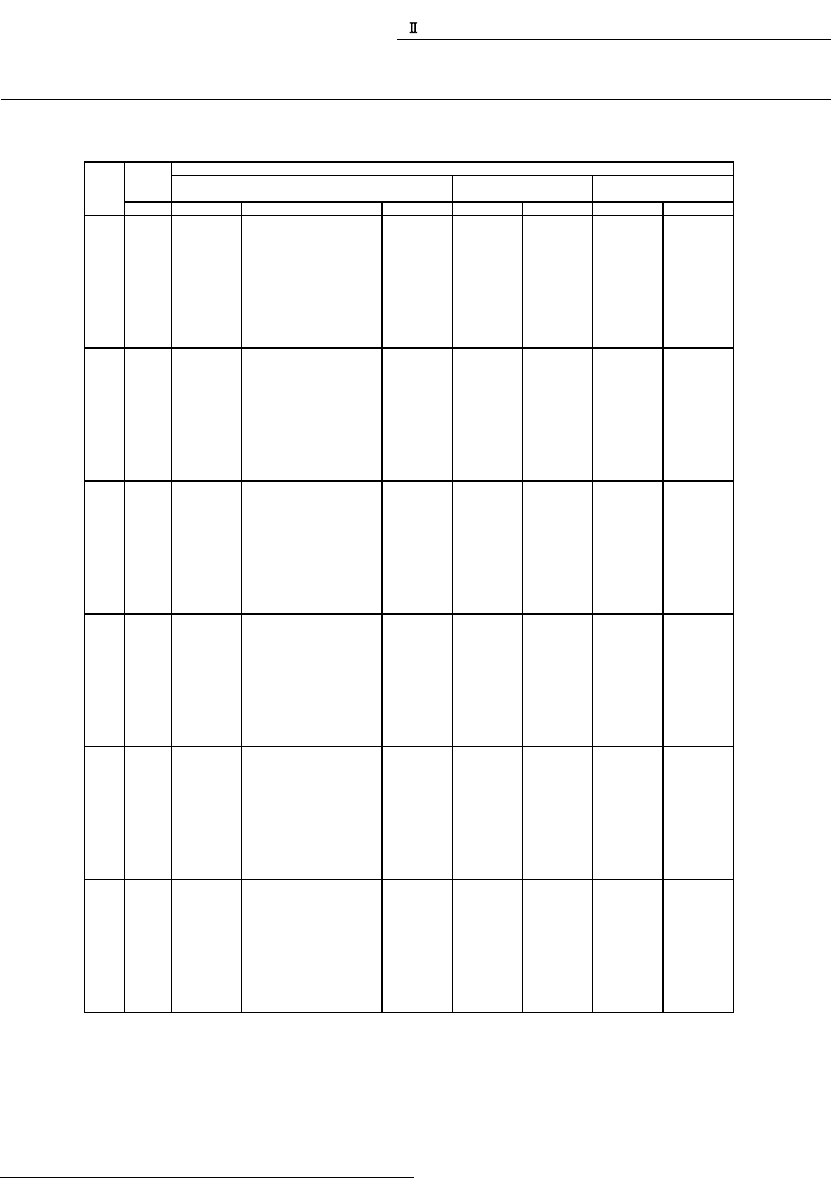
2. Capacity T ables
2-1.Cooling Capacity (In combination with PUMY)
PLFY-P-VLMD-B SHC:Sensible heat Capacity(kW)
Outdoor Indoor air temp.
Unit
air temp.
size
˚CDB CA SHC CA SHC CA SHC CA SHC
20.0
20
25
32
40
50
63
22.5
25.0
27.5
30.0
32.5
35.0
37.5
40.0
46.0
20.0
22.5
25.0
27.5
30.0
32.5
35.0
37.5
40.0
46.0
20.0
22.5
25.0
27.5
30.0
32.5
35.0
37.5
40.0
46.0
20.0
22.5
25.0
27.5
30.0
32.5
35.0
37.5
40.0
46.0
20.0
22.5
25.0
27.5
30.0
32.5
35.0
37.5
40.0
46.0
20.0
22.5
25.0
27.5
30.0
32.5
35.0
37.5
40.0
46.0
(2.2)
(2.8)
(3.6)
(4.5)
(5.6)
(7.1)
23˚CDB 25˚CDB 28˚CDB 30˚CDB
16
˚CWB 18˚CWB 20˚CWB 22˚CWB
2.2
2.1
2.1
2.1
2.1
2.0
2.0
2.0
2.0
1.9
2.8
2.7
2.7
2.7
2.6
2.6
2.6
2.5
2.5
2.4
3.6
3.5
3.5
3.4
3.4
3.3
3.3
3.2
3.2
3.1
4.5
4.4
4.3
4.3
4.2
4.2
4.1
4.1
4.0
3.8
5.5
5.5
5.4
5.3
5.3
5.2
5.1
5.0
5.0
4.8
7.0
6.9
6.9
6.8
6.7
6.6
6.5
6.4
6.3
6.1
1.8
1.8
1.7
1.7
1.7
1.7
1.7
1.7
1.7
1.6
2.1
2.0
2.0
2.0
2.0
2.0
1.9
1.9
1.9
1.9
2.6
2.6
2.5
2.5
2.5
2.5
2.4
2.4
2.4
2.3
3.0
3.0
3.0
3.0
2.9
2.9
2.8
2.8
2.8
2.7
3.8
3.8
3.7
3.7
3.7
3.6
3.6
3.5
3.5
3.4
4.9
4.9
4.8
4.8
4.7
4.7
4.6
4.6
4.6
4.4
2.3
2.3
2.3
2.2
2.2
2.2
2.1
2.1
2.1
2.0
2.9
2.9
2.9
2.8
2.8
2.8
2.7
2.7
2.7
2.6
3.7
3.7
3.7
3.6
3.6
3.6
3.5
3.5
3.4
3.3
4.7
4.6
4.6
4.6
4.5
4.4
4.4
4.3
4.3
4.1
5.8
5.8
5.7
5.7
5.6
5.5
5.5
5.4
5.3
5.1
7.4
7.3
7.3
7.2
7.1
7.0
6.9
6.8
6.7
6.5
1.8
1.8
1.8
1.8
1.8
1.8
1.8
1.8
1.8
1.7
2.1
2.1
2.1
2.1
2.1
2.1
2.1
2.0
2.0
2.0
2.7
2.7
2.6
2.6
2.6
2.6
2.6
2.5
2.5
2.5
3.2
3.1
3.1
3.1
3.1
3.0
3.0
3.0
2.9
2.9
4.0
3.9
3.9
3.9
3.8
3.8
3.8
3.7
3.7
3.6
5.1
5.1
5.1
5.0
5.0
4.9
4.9
4.8
4.8
4.7
2.4
2.4
2.4
2.4
2.3
2.3
2.3
2.2
2.2
2.1
3.1
3.1
3.1
3.0
3.0
2.9
2.9
2.9
2.8
2.7
4.0
4.0
3.9
3.9
3.8
3.8
3.7
3.7
3.6
3.5
5.0
5.0
4.9
4.9
4.8
4.7
4.7
4.6
4.5
4.3
6.2
6.2
6.1
6.0
5.9
5.9
5.8
5.7
5.6
5.4
7.9
7.8
7.7
7.7
7.5
7.5
7.3
7.2
7.2
6.9
CA:Capacity(kW)
1.8
1.8
1.8
1.8
1.8
1.8
1.8
1.7
1.7
1.7
2.1
2.1
2.1
2.1
2.1
2.1
2.0
2.0
2.0
1.9
2.7
2.6
2.6
2.6
2.6
2.6
2.5
2.5
2.5
2.4
3.1
3.1
3.1
3.1
3.0
3.0
3.0
2.9
2.9
2.8
4.0
3.9
3.9
3.9
3.8
3.8
3.7
3.7
3.7
3.5
5.1
5.1
5.0
5.0
4.9
4.9
4.8
4.8
4.7
4.6
2.6
2.6
2.5
2.5
2.5
2.5
2.4
2.4
2.4
2.3
3.3
3.2
3.2
3.2
3.2
3.1
3.1
3.0
3.0
2.9
4.2
4.2
4.1
4.1
4.1
4.0
4.0
3.9
3.9
3.7
5.3
5.2
5.2
5.1
5.1
5.0
5.0
4.9
4.8
4.6
6.6
6.5
6.4
6.4
6.3
6.2
6.2
6.1
6.0
5.8
8.3
8.2
8.2
8.1
8.0
7.9
7.8
7.7
7.6
7.3
1.9
1.9
1.9
1.9
1.9
1.8
1.8
1.8
1.8
1.8
2.2
2.2
2.2
2.2
2.1
2.1
2.1
2.1
2.1
2.0
2.7
2.7
2.7
2.7
2.7
2.6
2.6
2.6
2.6
2.5
3.2
3.2
3.2
3.1
3.1
3.1
3.1
3.0
3.0
2.9
4.1
4.0
4.0
4.0
3.9
3.9
3.9
3.8
3.8
3.7
5.2
5.2
5.2
5.1
5.1
5.0
5.0
5.0
4.9
4.8
Page 4
4
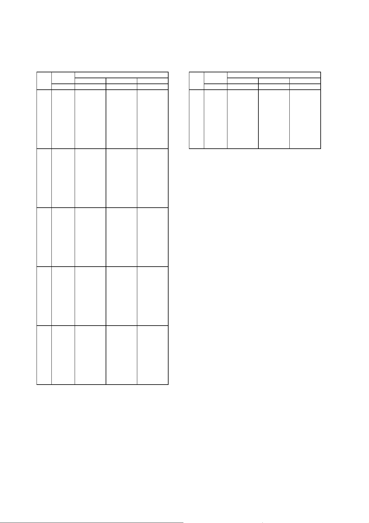
2-2.Heating Capacity (In combination with PUMY)
PLFY-P-VLMD-B SHC:Sensible heat Capacity(kW)
Outdoor Indoor air temp.:˚CDB
Unit
air temp. 15.0 20.0 25.0
size
˚CWB SHC SHC SHC ˚CWB SHC SHC SHC
-12.0
20 63
-10.0
-5.0
0.0
2.5
6.0
7.5
10.0
12.5
15.5
-12.0
25
-10.0
-5.0
0.0
2.5
6.0
7.5
10.0
12.5
15.5
-12.0
32
-10.0
-5.0
0.0
2.5
6.0
7.5
10.0
12.5
15.5
-12.0
40
-10.0
-5.0
0.0
2.5
6.0
7.5
10.0
12.5
15.5
-12.0
50
-10.0
-5.0
0.0
2.5
6.0
7.5
10.0
12.5
15.5
1.6
1.7
1.9
2.2
2.3
2.5
2.6
2.8
2.9
3.1
2.0
2.1
2.4
2.8
3.0
3.2
3.3
3.5
3.7
3.9
2.5
2.7
3.1
3.5
3.7
4.0
4.2
4.4
4.7
4.9
3.2
3.4
3.8
4.3
4.6
5.0
5.2
5.5
5.9
6.2
4.0
4.2
4.8
5.5
5.8
6.3
6.6
7.0
7.4
7.7
1.6
1.6
1.9
2.1
2.3
2.5
2.6
2.7
2.8
2.8
2.0
2.1
2.4
2.8
2.9
3.2
3.3
3.5
3.5
3.5
2.5
2.6
3.0
3.4
3.7
4.0
4.1
4.4
4.4
4.4
3.1
3.3
3.8
4.3
4.6
5.0
5.2
5.5
5.5
5.5
3.9
4.2
4.8
5.4
5.8
6.3
6.5
6.9
7.0
7.0
1.5
1.6
1.9
2.1
2.3
2.5
2.5
2.5
2.5
2.5
2.0
2.1
2.4
2.7
2.9
3.2
3.2
3.2
3.2
3.2
2.5
2.6
3.0
3.4
3.6
3.9
4.0
4.0
4.0
4.0
3.1
3.2
3.7
4.2
4.5
4.9
5.0
5.0
5.0
5.0
3.9
4.1
4.7
5.3
5.7
6.2
6.2
6.2
6.2
6.2
Outdoor Indoor air temp.:˚CDB
Unit
air temp. 15.0 20.0 25.0
size
-12.0
-10.0
-5.0
0.0
2.5
6.0
7.5
10.0
12.5
15.5
5.1
5.4
6.1
6.9
7.4
8.0
8.3
8.8
9.4
9.8
5.0
5.3
6.0
6.9
7.3
8.0
8.3
8.8
8.8
8.8
4.9
5.2
5.9
6.8
7.2
7.9
7.9
7.9
7.9
7.9
Page 5
5
Indoor units / Cassette ceiling / 2-way flow /
PLFY-P-VLMD-B
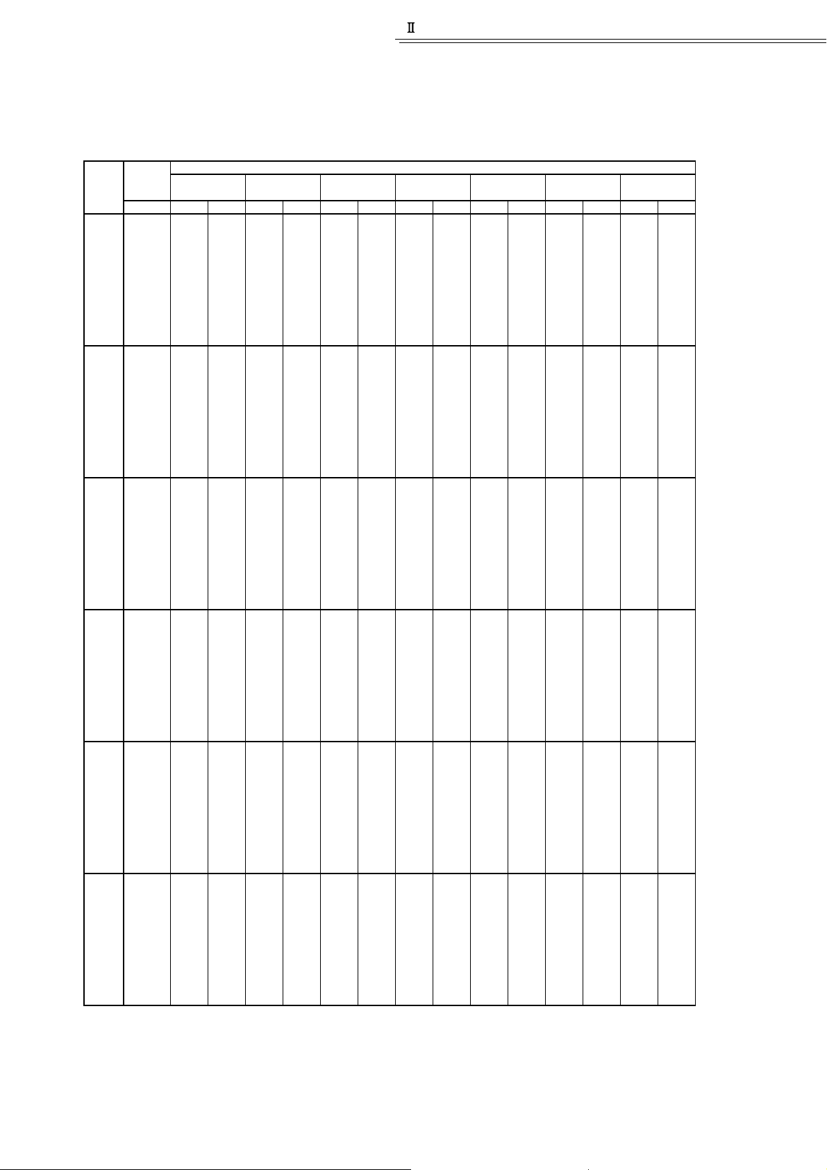
2-3.Cooling Capacity (In combination with Y,R2)
PLFY-P-VLMD-B SHC:Sensible heat Capacity(kW)
Outdoor Indoor air temp.
Unit
air temp.
size
˚CDB CA SHC CA SHC CA SHC CA SHC CA SHC CA SHC CA SHC
20.0
20
25
32
40
50
63
22.5
25.0
27.5
30.0
32.5
35.0
37.5
40.0
43.0
20.0
22.5
25.0
27.5
30.0
32.5
35.0
37.5
40.0
43.0
20.0
22.5
25.0
27.5
30.0
32.5
35.0
37.5
40.0
43.0
20.0
22.5
25.0
27.5
30.0
32.5
35.0
37.5
40.0
43.0
20.0
22.5
25.0
27.5
30.0
32.5
35.0
37.5
40.0
43.0
20.0
22.5
25.0
27.5
30.0
32.5
35.0
37.5
40.0
43.0
(2.2)
(2.8)
(3.6)
(4.5)
(5.6)
(7.1)
21.5
˚CDB 23˚CDB 25˚CDB 27˚CDB 28˚CDB 30˚CDB 32˚CDB
15
˚CWB 16˚CWB 18˚CWB 19˚CWB 20˚CWB 22˚CWB 24˚CWB
2.2
1.8
2.2
1.8
2.3
1.8
2.3
1.8
2.1
2.1
2.1
2.1
2.0
2.0
2.0
2.0
2.0
2.7
2.7
2.7
2.7
2.6
2.6
2.6
2.5
2.5
2.5
3.5
3.5
3.5
3.4
3.4
3.3
3.3
3.3
3.2
3.2
4.4
4.4
4.3
4.3
4.2
4.2
4.1
4.1
4.1
4.0
5.5
5.4
5.4
5.3
5.3
5.2
5.2
5.1
5.0
5.0
7.0
6.9
6.8
6.7
6.7
6.6
6.5
6.5
6.4
6.3
1.7
1.7
1.7
1.7
1.7
1.7
1.7
1.7
1.7
2.0
2.0
2.0
2.0
2.0
2.0
2.0
1.9
1.9
1.9
2.6
2.5
2.5
2.5
2.5
2.5
2.4
2.4
2.4
2.4
3.0
3.0
3.0
2.9
2.9
2.9
2.9
2.8
2.8
2.8
3.8
3.8
3.7
3.7
3.7
3.6
3.6
3.6
3.5
3.5
4.9
4.9
4.8
4.8
4.7
4.7
4.7
4.6
4.6
4.5
2.2
2.2
2.1
2.1
2.1
2.1
2.0
2.0
2.0
2.8
2.8
2.7
2.7
2.7
2.7
2.6
2.6
2.6
2.5
3.6
3.6
3.5
3.5
3.5
3.4
3.4
3.3
3.3
3.3
4.5
4.5
4.4
4.4
4.3
4.3
4.2
4.2
4.1
4.1
5.6
5.5
5.5
5.4
5.4
5.3
5.3
5.2
5.2
5.1
7.1
7.0
7.0
6.9
6.8
6.7
6.7
6.6
6.5
6.4
1.8
1.8
1.8
1.8
1.8
1.7
1.7
1.7
1.7
2.1
2.1
2.1
2.0
2.0
2.0
2.0
2.0
2.0
2.0
2.6
2.6
2.6
2.6
2.5
2.5
2.5
2.5
2.5
2.4
3.1
3.0
3.0
3.0
3.0
2.9
2.9
2.9
2.9
2.8
3.8
3.8
3.8
3.8
3.7
3.7
3.7
3.6
3.6
3.6
5.0
4.9
4.9
4.9
4.8
4.8
4.8
4.7
4.7
4.6
2.3
2.2
2.2
2.2
2.2
2.2
2.1
2.1
2.1
2.9
2.9
2.9
2.8
2.8
2.8
2.7
2.7
2.7
2.7
3.7
3.7
3.7
3.6
3.6
3.6
3.5
3.5
3.5
3.4
4.7
4.6
4.6
4.5
4.5
4.5
4.4
4.4
4.3
4.3
5.8
5.8
5.7
5.7
5.6
5.5
5.5
5.4
5.4
5.3
7.4
7.3
7.2
7.2
7.1
7.0
7.0
6.9
6.8
6.7
1.8
1.7
1.7
1.7
1.7
1.7
1.7
1.7
1.7
2.0
2.0
2.0
2.0
2.0
2.0
2.0
2.0
1.9
1.9
2.5
2.5
2.5
2.5
2.5
2.5
2.4
2.4
2.4
2.4
3.0
3.0
2.9
2.9
2.9
2.9
2.8
2.8
2.8
2.8
3.8
3.7
3.7
3.7
3.6
3.6
3.6
3.6
3.5
3.5
4.9
4.8
4.8
4.8
4.7
4.7
4.7
4.6
4.6
4.5
2.3
2.3
2.3
2.2
2.2
2.2
2.2
2.2
2.1
3.0
2.9
2.9
2.9
2.9
2.8
2.8
2.8
2.7
2.7
3.8
3.8
3.7
3.7
3.7
3.6
3.6
3.6
3.5
3.5
4.8
4.7
4.7
4.6
4.6
4.5
4.5
4.5
4.4
4.4
5.9
5.9
5.8
5.8
5.7
5.7
5.6
5.5
5.5
5.4
7.5
7.5
7.4
7.3
7.2
7.2
7.1
7.0
7.0
6.9
1.8
1.8
1.8
1.8
1.8
1.7
1.7
1.7
1.7
2.1
2.0
2.0
2.0
2.0
2.0
2.0
2.0
2.0
1.9
2.6
2.5
2.5
2.5
2.5
2.5
2.5
2.5
2.4
2.4
3.0
3.0
2.9
2.9
2.9
2.9
2.8
2.8
2.8
2.8
3.8
3.7
3.7
3.7
3.6
3.6
3.6
3.6
3.5
3.5
4.9
4.8
4.8
4.8
4.7
4.7
4.7
4.6
4.6
4.6
2.4
2.4
2.3
2.3
2.3
2.3
2.2
2.2
2.2
2.2
3.0
3.0
3.0
2.9
2.9
2.9
2.9
2.8
2.8
2.8
3.9
3.9
3.8
3.8
3.7
3.7
3.7
3.6
3.6
3.6
4.9
4.8
4.8
4.7
4.7
4.6
4.6
4.5
4.5
4.4
6.0
6.0
5.9
5.9
5.8
5.8
5.7
5.7
5.6
5.5
7.7
7.6
7.5
7.5
7.4
7.3
7.2
7.2
7.1
7.0
CA:Capacity(kW)
1.9
1.8
1.8
1.8
1.8
1.8
1.8
1.8
1.8
1.8
2.1
2.1
2.1
2.1
2.1
2.1
2.0
2.0
2.0
2.0
2.6
2.6
2.6
2.6
2.6
2.6
2.5
2.5
2.5
2.5
3.1
3.0
3.0
3.0
3.0
2.9
2.9
2.9
2.9
2.9
3.8
3.8
3.8
3.8
3.7
3.7
3.7
3.7
3.6
3.6
5.0
5.0
4.9
4.9
4.9
4.8
4.8
4.8
4.8
4.7
2.5
2.4
2.4
2.4
2.4
2.4
2.3
2.3
2.3
2.3
3.1
3.1
3.1
3.1
3.0
3.0
3.0
2.9
2.9
2.9
4.0
4.0
4.0
3.9
3.9
3.9
3.8
3.8
3.7
3.7
5.0
5.0
5.0
4.9
4.9
4.8
4.8
4.7
4.7
4.6
6.3
6.2
6.2
6.1
6.0
6.0
5.9
5.9
5.8
5.8
8.0
7.9
7.8
7.7
7.7
7.6
7.5
7.5
7.4
7.3
1.8
1.8
1.8
1.8
1.8
1.8
1.8
1.8
1.8
1.7
2.1
2.1
2.0
2.0
2.0
2.0
2.0
2.0
2.0
2.0
2.6
2.6
2.5
2.5
2.5
2.5
2.5
2.5
2.5
2.4
3.0
2.9
2.9
2.9
2.9
2.9
2.8
2.8
2.8
2.8
3.7
3.7
3.7
3.7
3.6
3.6
3.6
3.6
3.6
3.5
4.9
4.8
4.8
4.8
4.7
4.7
4.7
4.7
4.6
4.6
2.6
2.5
2.5
2.5
2.5
2.4
2.4
2.4
2.4
2.3
3.2
3.2
3.2
3.2
3.1
3.1
3.1
3.1
3.0
3.0
4.2
4.1
4.1
4.1
4.0
4.0
4.0
3.9
3.9
3.8
5.2
5.2
5.1
5.1
5.0
5.0
5.0
4.9
4.9
4.8
6.5
6.4
6.4
6.3
6.3
6.2
6.2
6.1
6.0
6.0
8.2
8.2
8.1
8.0
8.0
7.9
7.8
7.7
7.7
7.6
1.8
1.8
1.8
1.7
1.7
1.7
1.7
1.7
1.7
1.7
2.0
2.0
2.0
2.0
2.0
2.0
1.9
1.9
1.9
1.9
2.5
2.5
2.5
2.5
2.4
2.4
2.4
2.4
2.4
2.4
2.9
2.8
2.8
2.8
2.8
2.8
2.8
2.7
2.7
2.7
3.6
3.6
3.6
3.6
3.5
3.5
3.5
3.5
3.4
3.4
4.7
4.7
4.7
4.6
4.6
4.6
4.6
4.5
4.5
4.5
Page 6
2-4.Heating Capacity (In combination with Y,R2)
6
PLFY-P-VLMD-B
Outdoor
Unit
air temp.
size
˚CWB
-15.0
20
-10.0
-5.0
0.0
2.5
6.0
7.5
10.0
12.5
15.5
-15.0
25
-10.0
-5.0
0.0
2.5
6.0
7.5
10.0
12.5
15.5
-15.0
32
-10.0
-5.0
0.0
2.5
6.0
7.5
10.0
12.5
15.5
-15.0
40
-10.0
-5.0
0.0
2.5
6.0
7.5
10.0
12.5
15.5
-15.0
50
-10.0
-5.0
0.0
2.5
6.0
7.5
10.0
12.5
15.5
Indoor air temp.:˚CDB Indoor air temp.:˚CDB
15.0 20.0 25.0 27.0 15.0 20.0 25.0 27.0
SHC SHC SHC SHC SHC SHC SHC SHC
1.7
1.9
2.1
2.4
2.5
2.5
2.6
2.8
3.0
3.0
2.1
2.4
2.7
3.1
3.2
3.2
3.4
3.6
3.8
3.9
2.7
3.1
3.4
3.8
4.0
4.0
4.2
4.5
4.8
4.8
3.3
3.8
4.3
4.8
5.0
5.1
5.3
5.6
6.0
6.1
4.2
4.8
5.4
6.0
6.3
6.4
6.6
7.1
7.5
7.6
1.6
1.9
2.1
2.4
2.5
2.5
2.5
2.5
2.5
2.5
2.1
2.4
2.7
3.0
3.2
3.2
3.2
3.2
3.2
3.2
2.6
3.0
3.4
3.8
4.0
4.0
4.0
4.0
4.0
4.0
3.3
3.8
4.2
4.7
5.0
5.0
5.0
5.0
5.0
5.0
4.2
4.8
5.3
5.9
6.2
6.3
6.3
6.3
6.3
6.3
1.6
1.9
2.0
2.0
2.0
2.0
2.0
2.0
2.0
2.0
2.1
2.4
2.5
2.5
2.5
2.5
2.5
2.5
2.5
2.5
2.6
3.0
3.1
3.1
3.1
3.1
3.1
3.1
3.1
3.1
3.3
3.7
3.9
3.9
3.9
3.9
3.9
3.9
3.9
3.9
4.1
4.7
4.9
4.9
4.9
4.9
4.9
4.9
4.9
4.9
1.6
1.7
1.7
1.7
1.7
1.7
1.7
1.7
1.7
1.7
2.1
2.2
2.2
2.2
2.2
2.2
2.2
2.2
2.2
2.2
2.6
2.8
2.8
2.8
2.8
2.8
2.8
2.8
2.8
2.8
3.3
3.5
3.5
3.5
3.5
3.5
3.5
3.5
3.5
3.5
4.1
4.3
4.3
4.3
4.3
4.3
4.3
4.3
4.3
4.3
Unit
size
63
Outdoor
air temp.
˚CWB
-15.0
-10.0
-5.0
0.0
2.5
6.0
7.5
10.0
12.5
15.5
5.4
6.1
6.9
7.6
8.0
8.1
8.4
9.0
9.6
9.7
SHC:Sensible heat Capacity(kW)
5.3
6.0
6.8
7.5
7.9
8.0
8.0
8.0
8.0
8.0
5.2
6.0
6.2
6.2
6.2
6.2
6.2
6.2
6.2
6.2
5.2
5.5
5.5
5.5
5.5
5.5
5.5
5.5
5.5
5.5
Page 7

7
Indoor units / Cassette ceiling / 2-way flow /
PLFY-P-VLMD-B
2-5.Cooling Capacity (In combination with Big Y, Super Y, Big R2)
PLFY-P-VLMD-B
Outdoor
Unit
air temp.
size
˚CDB
20.0
20
22.5
25.0
27.5
30.0
32.5
35.0
37.5
40.0
43.0
20.0
25
22.5
25.0
27.5
30.0
32.5
35.0
37.5
40.0
43.0
20.0
32
22.5
25.0
27.5
30.0
32.5
35.0
37.5
40.0
43.0
20.0
40
22.5
25.0
27.5
30.0
32.5
35.0
37.5
40.0
43.0
20.0
50
22.5
25.0
27.5
30.0
32.5
35.0
37.5
40.0
43.0
20.0
63
22.5
25.0
27.5
30.0
32.5
35.0
37.5
40.0
43.0
Indoor air temp.
˚CDB 23˚CDB 25˚CDB 28˚CDB 30˚CDB 32˚CDB
21.5
15
˚CWB 16˚CWB 18˚CWB 20˚CWB 22˚CWB 24˚CWB
CA SHC CA SHC CA SHC CA SHC CA SHC CA SHC
2.0
2.0
2.0
2.0
2.0
2.0
1.9
1.9
1.9
1.9
2.6
2.6
2.6
2.5
2.5
2.5
2.5
2.5
2.4
2.4
3.3
3.3
3.3
3.3
3.2
3.2
3.2
3.2
3.1
3.1
4.1
4.1
4.1
4.1
4.0
4.0
4.0
3.9
3.9
3.9
5.2
5.2
5.1
5.1
5.0
5.0
4.9
4.9
4.9
4.8
6.5
6.5
6.5
6.4
6.4
6.3
6.3
6.2
6.2
6.1
1.7
1.7
1.7
1.7
1.7
1.7
1.7
1.7
1.6
1.6
2.0
2.0
1.9
1.9
1.9
1.9
1.9
1.9
1.9
1.9
2.4
2.4
2.4
2.4
2.4
2.4
2.4
2.4
2.4
2.3
2.9
2.9
2.8
2.8
2.8
2.8
2.8
2.8
2.7
2.7
3.6
3.6
3.6
3.6
3.5
3.5
3.5
3.5
3.5
3.4
4.7
4.7
4.6
4.6
4.6
4.6
4.5
4.5
4.5
4.4
2.1
2.1
2.1
2.1
2.1
2.0
2.0
2.0
2.0
1.9
2.7
2.7
2.7
2.6
2.6
2.6
2.6
2.5
2.5
2.5
3.5
3.5
3.4
3.4
3.4
3.3
3.3
3.3
3.2
3.2
4.3
4.3
4.3
4.2
4.2
4.2
4.1
4.1
4.0
4.0
5.4
5.4
5.3
5.3
5.2
5.2
5.1
5.1
5.0
5.0
6.9
6.8
6.8
6.7
6.6
6.6
6.5
6.4
6.4
6.3
1.8
1.8
1.8
1.7
1.7
1.7
1.7
1.7
1.7
1.7
2.0
2.0
2.0
2.0
2.0
2.0
2.0
2.0
1.9
1.9
2.5
2.5
2.5
2.5
2.5
2.5
2.5
2.4
2.4
2.4
3.0
3.0
2.9
2.9
2.9
2.9
2.9
2.8
2.8
2.8
3.7
3.7
3.7
3.7
3.7
3.6
3.6
3.6
3.5
3.5
4.8
4.8
4.8
4.8
4.7
4.7
4.7
4.6
4.6
4.6
2.3
2.3
2.2
2.2
2.2
2.2
2.1
2.1
2.1
2.1
2.9
2.9
2.9
2.8
2.8
2.8
2.7
2.7
2.7
2.6
3.7
3.7
3.7
3.6
3.6
3.5
3.5
3.5
3.4
3.4
4.7
4.6
4.6
4.5
4.5
4.4
4.4
4.3
4.3
4.2
5.8
5.8
5.7
5.6
5.6
5.5
5.4
5.4
5.3
5.2
7.4
7.3
7.2
7.2
7.1
7.0
6.9
6.8
6.7
6.6
1.8
1.8
1.7
1.7
1.7
1.7
1.7
1.7
1.7
1.7
2.0
2.0
2.0
2.0
2.0
2.0
2.0
1.9
1.9
1.9
2.5
2.5
2.5
2.5
2.5
2.5
2.4
2.4
2.4
2.4
3.0
3.0
2.9
2.9
2.9
2.9
2.8
2.8
2.8
2.7
3.8
3.7
3.7
3.7
3.6
3.6
3.6
3.5
3.5
3.5
4.9
4.8
4.8
4.7
4.7
4.7
4.6
4.6
4.6
4.5
2.4
2.4
2.4
2.4
2.3
2.3
2.3
2.2
2.2
2.2
3.1
3.1
3.0
3.0
3.0
2.9
2.9
2.8
2.8
2.8
4.0
4.0
3.9
3.9
3.8
3.8
3.7
3.7
3.6
3.5
5.0
4.9
4.9
4.8
4.8
4.7
4.6
4.6
4.5
4.4
6.2
6.2
6.1
6.0
5.9
5.8
5.8
5.7
5.6
5.5
7.9
7.8
7.7
7.6
7.5
7.4
7.3
7.2
7.1
7.0
1.9
1.9
1.9
1.9
1.8
1.8
1.8
1.8
1.8
1.8
2.2
2.1
2.1
2.1
2.1
2.1
2.1
2.0
2.0
2.0
2.7
2.7
2.6
2.6
2.6
2.6
2.6
2.5
2.5
2.5
3.1
3.1
3.1
3.0
3.0
3.0
2.9
2.9
2.9
2.9
3.9
3.9
3.9
3.8
3.8
3.8
3.7
3.7
3.7
3.6
5.1
5.1
5.0
5.0
4.9
4.9
4.8
4.8
4.8
4.7
CA:Capacity(kW)
SHC:Sensible heat Capacity(kW)
2.6
2.6
2.5
2.5
2.5
2.4
2.4
2.4
2.3
2.3
3.3
3.3
3.2
3.2
3.1
3.1
3.0
3.0
3.0
2.9
4.2
4.2
4.1
4.1
4.0
4.0
3.9
3.8
3.8
3.7
5.3
5.2
5.2
5.1
5.0
5.0
4.9
4.8
4.7
4.7
6.6
6.5
6.4
6.3
6.2
6.2
6.1
6.0
5.9
5.8
8.4
8.3
8.1
8.0
7.9
7.8
7.7
7.6
7.5
7.3
1.9
1.8
1.8
1.8
1.8
1.8
1.8
1.8
1.8
1.7
2.1
2.1
2.1
2.1
2.1
2.0
2.0
2.0
2.0
2.0
2.6
2.6
2.6
2.6
2.6
2.5
2.5
2.5
2.5
2.4
3.1
3.0
3.0
3.0
3.0
2.9
2.9
2.9
2.8
2.8
3.9
3.8
3.8
3.8
3.7
3.7
3.7
3.6
3.6
3.5
5.0
5.0
4.9
4.9
4.8
4.8
4.8
4.7
4.7
4.6
2.7
2.7
2.7
2.6
2.6
2.6
2.5
2.5
2.4
2.4
3.5
3.4
3.4
3.3
3.3
3.2
3.2
3.1
3.1
3.0
4.5
4.4
4.4
4.3
4.2
4.2
4.1
4.0
4.0
3.9
5.6
5.5
5.5
5.4
5.3
5.2
5.1
5.1
5.0
4.9
7.0
6.9
6.8
6.7
6.6
6.5
6.4
6.3
6.2
6.1
8.9
8.7
8.6
8.5
8.4
8.2
8.1
8.0
7.9
7.7
1.8
1.8
1.8
1.8
1.8
1.8
1.8
1.7
1.7
1.7
2.1
2.1
2.1
2.0
2.0
2.0
2.0
2.0
2.0
1.9
2.6
2.6
2.6
2.5
2.5
2.5
2.5
2.4
2.4
2.4
3.0
3.0
3.0
2.9
2.9
2.9
2.8
2.8
2.8
2.7
3.8
3.8
3.7
3.7
3.7
3.6
3.6
3.5
3.5
3.5
4.9
4.9
4.8
4.8
4.8
4.7
4.7
4.6
4.6
4.5
Page 8

8
2-6.Heating Capacity (In combination with Big Y,Super Y,Big R2)
PLFY-P-VLMD-B SHC:Sensible heat Capacity(kW)
Unit
size
20
25
32
40
50
Outdoor
air temp.
˚CWB
-15.0
-10.0
-5.0
0.0
2.5
6.0
7.5
10.0
12.5
15.5
-15.0
-10.0
-5.0
0.0
2.5
6.0
7.5
10.0
12.5
15.5
-15.0
-10.0
-5.0
0.0
2.5
6.0
7.5
10.0
12.5
15.5
-15.0
-10.0
-5.0
0.0
2.5
6.0
7.5
10.0
12.5
15.5
-15.0
-10.0
-5.0
0.0
2.5
6.0
7.5
10.0
12.5
15.5
Indoor air temp.:˚CDB
15.0 20.0 25.0 27.0
SHC(kW) SHC(kW) SHC(kW) SHC(kW)
1.6
1.8
2.0
2.2
2.4
2.5
2.6
2.7
2.9
2.9
2.0
2.3
2.6
2.9
3.0
3.2
3.3
3.5
3.7
3.7
2.5
2.8
3.2
3.6
3.8
4.0
4.2
4.4
4.6
4.6
3.1
3.6
4.0
4.5
4.7
5.0
5.2
5.4
5.7
5.8
3.9
4.5
5.0
5.6
5.9
6.4
6.6
6.9
7.2
7.2
1.5
1.8
2.0
2.2
2.3
2.5
2.5
2.5
2.5
2.5
2.0
2.2
2.5
2.8
3.0
3.2
3.2
3.2
3.2
3.2
2.5
2.8
3.2
3.5
3.7
4.0
4.0
4.0
4.0
4.0
3.1
3.5
4.0
4.4
4.7
5.0
5.0
5.0
5.0
5.0
3.9
4.4
5.0
5.6
5.9
6.3
6.3
6.3
6.3
6.3
1.5
1.7
2.0
2.1
2.1
2.1
2.1
2.1
2.1
2.1
1.9
2.2
2.5
2.7
2.7
2.7
2.7
2.7
2.7
2.7
2.4
2.8
3.1
3.4
3.4
3.4
3.4
3.4
3.4
3.4
3.0
3.5
3.9
4.3
4.3
4.3
4.3
4.3
4.3
4.3
3.8
4.3
4.9
5.4
5.4
5.4
5.4
5.4
5.4
5.4
1.5
1.7
1.9
1.9
1.9
1.9
1.9
1.9
1.9
1.9
1.9
2.2
2.5
2.5
2.5
2.5
2.5
2.5
2.5
2.5
2.4
2.7
3.1
3.1
3.1
3.1
3.1
3.1
3.1
3.1
3.0
3.4
3.9
3.9
3.9
3.9
3.9
3.9
3.9
3.9
3.7
4.3
4.9
4.9
4.9
4.9
4.9
4.9
4.9
4.9
Unit
size
63
Outdoor
air temp.
˚CWB
-15.0
-10.0
-5.0
0.0
2.5
6.0
7.5
10.0
12.5
15.5
Indoor air temp.:˚CDB
15.0 20.0 25.0 27.0
SHC(kW) SHC(kW) SHC(kW) SHC(kW)
5.0
5.7
6.4
7.2
7.5
8.1
8.3
8.7
9.1
9.2
4.9
5.6
6.3
7.1
7.5
8.0
8.0
8.0
8.0
8.0
4.8
5.5
6.2
6.8
6.8
6.8
6.8
6.8
6.8
6.8
4.7
5.4
6.2
6.2
6.2
6.2
6.2
6.2
6.2
6.2
Page 9

9
Indoor units / Cassette ceiling / 2-way flow /
PLFY-P-VLMD-B
2-7.Cooling Capacity (In combination with WR2)
PLFY-P-VLMD-B
Water
Unit
temp.
size
˚C
10
20
20
30
40
45
10
25
20
30
40
45
10
32
20
30
40
45
10
40
20
30
40
45
10
50
20
30
40
45
10
63
20
30
40
45
˚CDB 23˚CDB 25˚CDB 27˚CDB 28˚CDB 30˚CDB 32˚CDB
21.5
15
˚CWB 16˚CWB 18˚CWB 19˚CWB 20˚CWB 22˚CWB 24˚CWB
CA SHC CA SHC CA SHC CA SHC CA SHC CA SHC CA SHC
1.8
2.2
2.1
2.1
2.0
1.7
1.6
2.7
2.6
2.5
2.2
2.0
3.5
3.4
3.2
2.8
2.6
4.4
4.2
4.0
3.5
3.3
5.5
5.3
5.0
4.3
4.1
6.9
6.7
6.3
5.5
5.2
1.8
1.7
1.7
1.5
1.5
2.0
2.0
1.9
1.8
1.7
2.5
2.5
2.4
2.2
2.1
3.0
2.9
2.8
2.5
2.4
3.8
3.7
3.5
3.2
3.1
4.9
4.7
4.5
4.1
4.0
2.1
2.0
1.8
1.7
2.8
2.7
2.6
2.2
2.1
3.6
3.5
3.3
2.9
2.7
4.5
4.4
4.1
3.6
3.4
5.6
5.4
5.1
4.5
4.2
7.2
6.9
6.5
5.7
5.3
1.8
1.7
1.6
1.6
2.1
2.0
2.0
1.8
1.8
2.6
2.6
2.5
2.3
2.2
3.1
3.0
2.9
2.6
2.5
3.9
3.8
3.6
3.3
3.1
5.0
4.9
4.7
4.3
4.1
2.4
2.3
2.1
1.9
1.8
3.0
2.9
2.7
2.4
2.2
3.9
3.7
3.5
3.1
2.9
4.8
4.6
4.4
3.8
3.6
6.0
5.8
5.5
4.7
4.5
7.6
7.3
6.9
6.0
5.7
Indoor air temp.
2.4
1.8
2.3
1.8
2.2
1.7
1.9
1.6
1.8
1.6
3.1
2.1
3.0
2.0
2.8
2.0
2.4
1.8
2.3
1.7
4.0
2.6
3.8
2.5
3.6
2.4
3.1
2.2
3.0
2.2
5.0
3.1
4.8
3.0
4.5
2.8
3.9
2.6
3.7
2.5
6.2
3.8
5.9
3.7
5.6
3.6
4.9
3.2
4.6
3.1
7.8
5.0
7.5
4.8
7.1
4.6
6.2
4.2
5.8
4.1
1.8
1.8
1.7
1.6
1.6
2.1
2.1
2.0
1.8
1.8
2.6
2.6
2.5
2.3
2.2
3.1
3.0
2.8
2.6
2.5
3.9
3.8
3.6
3.3
3.2
5.0
4.9
4.7
4.3
4.1
2.5
2.4
2.3
2.0
1.9
3.2
3.1
2.9
2.5
2.4
4.1
3.9
3.7
3.2
3.0
5.1
4.9
4.6
4.0
3.8
6.3
6.1
5.8
5.0
4.7
8.0
7.8
7.3
6.4
6.0
CA:Capacity(kW)
SHC:Sensible heat Capacity(kW)
1.9
2.6
1.9
1.9
1.8
1.7
1.7
2.2
2.1
2.1
1.9
1.9
2.7
2.7
2.6
2.4
2.3
3.2
3.1
2.9
2.7
2.6
4.0
3.9
3.7
3.4
3.3
5.2
5.0
4.8
4.4
4.3
2.5
2.4
2.1
2.0
3.3
3.2
3.0
2.6
2.5
4.3
4.1
3.9
3.4
3.2
5.4
5.2
4.9
4.3
4.0
6.7
6.5
6.1
5.3
5.0
8.5
8.2
7.7
6.7
6.3
1.8
1.8
1.7
1.6
2.1
2.1
2.0
1.9
1.8
2.7
2.6
2.5
2.3
2.3
3.1
3.0
2.9
2.6
2.5
3.9
3.8
3.7
3.3
3.2
5.1
5.0
4.8
4.4
4.2
2.8
2.7
2.5
2.2
2.1
3.5
3.4
3.2
2.8
2.6
4.5
4.4
4.1
3.6
3.4
5.7
5.5
5.2
4.5
4.2
7.1
6.8
6.4
5.6
5.3
9.0
8.6
8.1
7.1
6.7
1.8
1.8
1.8
1.7
1.6
2.1
2.1
2.0
1.9
1.8
2.6
2.6
2.5
2.3
2.2
3.1
3.0
2.8
2.6
2.5
3.8
3.7
3.6
3.3
3.2
5.0
4.9
4.7
4.3
4.1
Page 10

10
2-8.Heating Capacity (In combination with WR2)
PLFY-P-VLMD-B
Water
Unit
size
temp.
˚C
10
20
20
30
40
45
10
25
20
30
40
45
10
32
20
30
40
45
10
40
20
30
40
45
10
50
20
30
40
45
10
63
20
30
40
45
15
SHC(kW)
2.2
2.6
2.6
2.7
2.9
2.8
3.3
3.3
3.4
3.8
3.5
4.1
4.1
4.3
4.7
4.4
5.2
5.2
5.4
5.9
5.5
6.5
6.5
6.7
7.4
7.0
8.2
8.2
8.6
9.4
19
SHC(kW)
2.2
2.6
2.6
2.7
2.9
2.8
3.3
3.3
3.4
3.7
3.5
4.1
4.1
4.2
4.7
4.3
5.1
5.1
5.3
5.8
5.5
6.4
6.4
6.7
7.3
6.9
8.2
8.2
8.5
9.3
Indoor air temp.:˚CDB
20
SHC(kW)
2.1
2.5
2.5
2.6
2.9
2.7
3.2
3.2
3.3
3.6
3.4
4.0
4.0
4.2
4.6
4.3
5.0
5.0
5.2
5.7
5.4
6.3
6.3
6.6
7.2
6.8
8.0
8.0
8.3
9.1
SHC:Sensible heat Capacity(kW)
25
SHC(kW)
1.7
2.0
2.0
2.1
2.3
2.2
2.6
2.6
2.7
2.9
2.7
3.2
3.2
3.3
3.6
3.4
4.0
4.0
4.2
4.6
4.3
5.0
5.0
5.2
5.7
5.4
6.4
6.4
6.7
7.3
27
SHC(kW)
1.5
1.8
1.8
1.9
2.1
2.0
2.3
2.3
2.4
2.6
2.4
2.9
2.9
3.0
3.3
3.1
3.6
3.6
3.7
4.1
3.9
4.5
4.5
4.7
5.2
4.9
5.8
5.8
6.0
6.6
Page 11

11
Indoor units / Cassette ceiling / 2-way flow /
PLFY-P-VLMD-B
2-9.Cooling Capacity (In combination with PU(H)Y-TM-C)
PLFY-P-VLMD-B
Outdoor
Unit
air temp.
size
20
25
32
40
50
63
˚CDB
20.0
22.5
25.0
27.5
30.0
32.5
35.0
37.5
40.0
43.0
20.0
22.5
25.0
27.5
30.0
32.5
35.0
37.5
40.0
43.0
20.0
22.5
25.0
27.5
30.0
32.5
35.0
37.5
40.0
43.0
20.0
22.5
25.0
27.5
30.0
32.5
35.0
37.5
40.0
43.0
20.0
22.5
25.0
27.5
30.0
32.5
35.0
37.5
40.0
43.0
20.0
22.5
25.0
27.5
30.0
32.5
35.0
37.5
40.0
43.0
21.5
CA SHC CA SHC CA SHC CA SHC CA SHC CA SHC
1870
1870
1864
1832
1801
1769
1738
1706
1675
1637
2337
2337
2330
2290
2251
2212
2172
2133
2094
2046
2945
2945
2935
2886
2836
2787
2737
2687
2638
2578
3740
3740
3727
3664
3601
3538
3476
3413
3350
3274
4675
4675
4659
4580
4502
4423
4344
4266
4187
4093
5890
5890
5871
5771
5672
5573
5474
5375
5276
5157
˚CDB 23˚CDB 25˚CDB 27˚CDB 28˚CDB 30˚CDB
15
˚CWB 16˚CWB 18˚CWB 19.5˚CWB 20˚CWB 22˚CWB
1518
1518
1515
1501
1486
1472
1457
1443
1428
1411
1744
1744
1740
1721
1701
1682
1663
1644
1625
1602
2153
2153
2148
2123
2098
2074
2049
2025
2000
1971
2563
2563
2556
2521
2486
2452
2418
2383
2350
2310
3234
3234
3226
3183
3140
3098
3056
3014
2973
2923
4156
4156
4145
4093
4041
3989
3938
3887
3836
3776
1939
1939
1926
1895
1864
1832
1801
1770
1738
1700
2424
2424
2408
2369
2330
2290
2251
2212
2173
2126
3054
3054
3034
2985
2935
2886
2836
2787
2738
2678
3878
3878
3853
3790
3727
3664
3602
3539
3476
3401
4847
4847
4816
4737
4659
4581
4502
4424
4345
4251
6108
6108
6068
5969
5870
5772
5673
5574
5475
5357
1574
1574
1568
1554
1540
1526
1512
1498
1484
1468
1801
1801
1793
1775
1756
1737
1719
1700
1682
1660
2222
2222
2212
2188
2164
2140
2116
2092
2069
2040
2633
2633
2620
2586
2552
2519
2486
2453
2420
2381
3326
3326
3309
3267
3226
3185
3144
3104
3064
3016
4279
4279
4258
4208
4157
4107
4058
4008
3959
3901
2077
2077
2050
2017
1984
1950
1917
1884
1851
1811
2596
2596
2563
2521
2480
2438
2397
2355
2313
2264
3271
3271
3229
3177
3124
3072
3020
2967
2915
2852
4154
4154
4100
4034
3967
3901
3834
3768
3701
3622
5192
5192
5126
5042
4959
4876
4793
4710
4627
4527
6542
6542
6458
6354
6249
6144
6039
5935
5830
5704
Indoor air temp.
1567
1567
1556
1542
1528
1514
1500
1486
1472
1456
1794
1794
1779
1761
1742
1724
1705
1687
1669
1647
2214
2214
2195
2171
2147
2123
2099
2076
2052
2025
2629
2629
2602
2568
2535
2501
2468
2436
2403
2364
3318
3318
3285
3244
3203
3162
3122
3082
3042
2994
4266
4266
4226
4176
4126
4076
4027
3978
3929
3871
2180
2180
2150
2112
2075
2037
2000
1963
1925
1880
2725
2725
2687
2640
2593
2547
2500
2453
2407
2350
3434
3434
3385
3327
3268
3209
3150
3091
3032
2962
4361
4361
4299
4224
4150
4075
4000
3925
3850
3761
5451
5451
5374
5280
5187
5093
5000
4907
4813
4701
6868
6868
6771
6653
6535
6418
6300
6182
6065
5923
1614
1614
1601
1586
1571
1556
1542
1527
1512
1495
1841
1841
1824
1804
1784
1765
1745
1725
1706
1683
2268
2268
2247
2222
2196
2171
2146
2121
2096
2066
2682
2682
2652
2616
2580
2545
2509
2474
2440
2398
3388
3388
3352
3307
3263
3220
3177
3134
3091
3041
4362
4362
4318
4264
4210
4157
4105
4052
4000
3939
2215
2207
2171
2134
2097
2060
2023
1986
1950
1905
2768
2759
2713
2667
2621
2575
2529
2483
2437
2382
3488
3477
3419
3361
3303
3245
3187
3129
3071
3001
4430
4415
4341
4268
4194
4120
4047
3973
3899
3811
5537
5519
5426
5334
5242
5150
5058
4966
4874
4764
6977
6953
6837
6721
6605
6489
6373
6257
6141
6002
1666
1663
1648
1634
1619
1605
1590
1576
1562
1545
1892
1888
1869
1850
1831
1811
1792
1774
1755
1732
2330
2325
2300
2275
2251
2226
2202
2177
2153
2124
2742
2735
2700
2665
2630
2596
2561
2527
2494
2454
3467
3458
3415
3372
3330
3288
3247
3205
3164
3115
4471
4461
4408
4356
4305
4253
4202
4151
4101
4041
CA:Capacity(kcal/h)
SHC:Sensible heat Capacity(kcal/h)
32˚CDB
24
˚CWB
CA SHC
2353
2330
2292
2254
2216
2178
2140
2101
2063
2018
2941
2912
2865
2817
2770
2722
2674
2627
2579
2522
3706
3670
3610
3550
3490
3430
3370
3310
3250
3178
4705
4660
4584
4507
4431
4355
4279
4203
4127
4035
5882
5825
5729
5634
5539
5444
5349
5254
5159
5044
7411
7339
7219
7099
6979
6859
6740
6620
6500
6356
1646
1637
1623
1610
1596
1582
1568
1555
1541
1525
1869
1858
1840
1821
1803
1784
1766
1748
1730
1709
2301
2287
2263
2239
2216
2192
2169
2145
2122
2095
2710
2689
2656
2622
2588
2555
2522
2490
2457
2419
3425
3400
3359
3318
3277
3236
3196
3156
3117
3070
4416
4385
4335
4285
4236
4186
4137
4089
4040
3983
2491
2451
2411
2372
2332
2293
2253
2213
2174
2126
3113
3064
3014
2965
2915
2866
2816
2767
2717
2658
3923
3860
3798
3736
3673
3611
3548
3486
3424
3349
4981
4902
4823
4744
4664
4585
4506
4427
4347
4252
6227
6128
6028
5929
5830
5731
5632
5533
5434
5315
7846
7721
7596
7471
7346
7221
7097
6972
6847
6697
1621
1607
1594
1581
1568
1554
1541
1528
1515
1500
1839
1821
1804
1786
1768
1751
1733
1716
1699
1678
2264
2241
2218
2195
2172
2149
2127
2105
2082
2056
2664
2631
2599
2566
2534
2502
2471
2439
2408
2371
3367
3327
3287
3248
3209
3170
3131
3093
3055
3009
4341
4292
4244
4196
4149
4101
4054
4008
3961
3906
Page 12

2-10.Heating Capacity (In combination with PU(H)Y-TM-C)
12
PLFY-P-VLMD-B SHC:Sensible heat Capacity(kcal/h)
Unit Outdoor
air temp.
size
˚CWB SHC SHC SHC
-15.0
20
-10.0
-5.0
0.0
2.5
6.0
7.5
10.0
12.5
15.5
25
-15.0
-10.0
-5.0
0.0
2.5
6.0
7.5
10.0
12.5
15.5
32
-15.0
-10.0
-5.0
0.0
2.5
6.0
7.5
10.0
12.5
15.5
40
-15.0
-10.0
-5.0
0.0
2.5
6.0
7.5
10.0
12.5
15.5
50
-15.0
-10.0
-5.0
0.0
2.5
6.0
7.5
10.0
12.5
15.5
1555
1774
1994
2213
2322
2343
2441
2605
2769
2807
1935
2208
2481
2754
2890
2915
3038
3242
3446
3493
2454
2800
3146
3491
3664
3696
3852
4111
4370
4428
3111
3549
3987
4426
4645
4686
4883
5211
5539
5613
3871
4416
4962
5508
5780
5831
6076
6484
6893
6986
Indoor air temp.:˚CDB
15 21 25
1532
1751
1970
2190
2250
2250
2250
2250
2250
2250
1907
2179
2452
2725
2800
2800
2800
2800
2800
2800
2417
2763
3109
3455
3550
3550
3550
3550
3550
3550
3064
3503
3941
4379
4500
4500
4500
4500
4500
4500
3813
4359
4904
5450
5600
5600
5600
5600
5600
5600
1509
1728
1809
1809
1809
1809
1809
1809
1809
1809
1878
2151
2252
2252
2252
2252
2252
2252
2252
2252
2381
2727
2855
2855
2855
2855
2855
2855
2855
2855
3018
3456
3619
3619
3619
3619
3619
3619
3619
3619
3755
4301
4503
4503
4503
4503
4503
4503
4503
4503
27
SHC
1500
1601
1601
1601
1601
1601
1601
1601
1601
1601
1866
1992
1992
1992
1992
1992
1992
1992
1992
1992
2366
2525
2525
2525
2525
2525
2525
2525
2525
2525
2999
3201
3201
3201
3201
3201
3201
3201
3201
3201
3732
3984
3984
3984
3984
3984
3984
3984
3984
3984
Unit Outdoor
air temp.
size
˚CWB SHC SHC SHC
63
-15.0
-10.0
-5.0
0.0
2.5
6.0
7.5
10.0
12.5
15.5
4908
5599
6291
6983
7329
7393
7704
8221
8739
8857
Indoor air temp.:˚CDB
15 21 25
4835
5526
6218
6910
7100
7100
7100
7100
7100
7100
4761
5453
5709
5709
5709
5709
5709
5709
5709
5709
27
SHC
4732
5051
5051
5051
5051
5051
5051
5051
5051
5051
Page 13

13
Indoor units / Cassette ceiling / 2-way flow /
PLFY-P-VLMD-B
3. Sound Levels
3-1. Noise level
PLFY-P20VLMD-B
PLFY-P25VLMD-B
PLFY-P32VLMD-B
PLFY-P40VLMD-B
PLFY-P50VLMD-B
PLFY-P63VLMD-B
Noise level (A weighted)
220V,240V
27-30-33
29-33-36
31-34-37
32-37-39
230V
28-31-34
30-34-37
32-35-38
33-38-40
Noise level at anechoic room
( Low - Middle - High ) Unit : dB(A)
Model
1.5m
Casette ceiling (VLMD-B series)
Measured point
3-2. NC curves
NC=70
NC=60
NC=50
NC=40
NC=30
NC=20
Approximate minimum
audible limit on
continuous noise
63
125 250 500 1000 2000 4000 8000
90
80
70
60
50
40
30
20
10
PLFY-P20,25VLMD-B(220V,240V)
OCTAVE BAND PRESSURE LEVEL< dB> 0dB = 20µPa
OCTAVE BAND CENTER FREQUENCIES<Hz>
High
Middle
Low
NC=70
NC=60
NC=50
NC=40
NC=30
NC=20
Approximate minimum
audible limit on
continuous noise
63
125 250 500 1000 2000 4000 8000
90
80
70
60
50
40
30
20
10
PLFY-P20,25VLMD-B(230V)
OCTAVE BAND PRESSURE LEVEL< dB> 0dB = 20µPa
OCTAVE BAND CENTER FREQUENCIES<Hz>
High
Middle
Low
NC=70
NC=60
NC=50
NC=40
NC=30
NC=20
Approximate minimum
audible limit on
continuous noise
63
125 250 500 1000 2000 4000 8000
90
80
70
60
50
40
30
20
10
PLFY-P32VLMD-B(220V,240V)
OCTAVE BAND PRESSURE LEVEL< dB> 0dB = 20µPa
OCTAVE BAND CENTER FREQUENCIES<Hz>
High
Middle
Low
NC=70
NC=60
NC=50
NC=40
NC=30
NC=20
Approximate minimum
audible limit on
continuous noise
63
125 250 500 1000 2000 4000 8000
90
80
70
60
50
40
30
20
10
PLFY-P32VLMD-B(230V)
OCTAVE BAND PRESSURE LEVEL< dB> 0dB = 20µPa
OCTAVE BAND CENTER FREQUENCIES<Hz>
High
Middle
Low
NC=70
NC=60
NC=50
NC=40
NC=30
NC=20
Approximate minimum
audible limit on
continuous noise
63
125 250 500 1000 2000 4000 8000
90
80
70
60
50
40
30
20
10
PLFY-P40VLMD-B(220V,240V)
OCTAVE BAND PRESSURE LEVEL< dB> 0dB = 20µPa
OCTAVE BAND CENTER FREQUENCIES<Hz>
High
Middle
Low
NC=70
NC=60
NC=50
NC=40
NC=30
NC=20
Approximate minimum
audible limit on
continuous noise
63
125 250 500 1000 2000 4000 8000
90
80
70
60
50
40
30
20
10
PLFY-P40VLMD-B(230V)
OCTAVE BAND PRESSURE LEVEL< dB> 0dB = 20µPa
OCTAVE BAND CENTER FREQUENCIES<Hz>
High
Middle
Low
PLFY-P50VLMD-B(230V)
PLFY-P50VLMD-B(220V,240V)
Page 14

14
PLFY-P50VLMD-B(220V,240V)
3-3. OA Intake-static pressure curve
90
80
70
60
50
40
30
OCTAVE BAND PRESSURE LEVEL< dB> 0dB = 20µPa
20
Approximate minimum
audible limit on
continuous noise
10
63
125 250 500 1000 2000 4000 8000
OCTAVE BAND CENTER FREQUENCIES<Hz>
PLFY-P63VLMD-B(220V,240V)
90
80
70
60
50
40
30
OCTAVE BAND PRESSURE LEVEL< dB> 0dB = 20µPa
20
Approximate minimum
audible limit on
continuous noise
10
63
125 250 500 1000 2000 4000 8000
OCTAVE BAND CENTER FREQUENCIES<Hz>
High
Middle
Low
NC=70
NC=60
NC=50
NC=40
NC=30
NC=20
High
Middle
Low
NC=70
NC=60
NC=50
NC=40
NC=30
NC=20
PLFY-P50VLMD-B(230V)
90
80
70
60
50
40
30
OCTAVE BAND PRESSURE LEVEL< dB> 0dB = 20µPa
20
Approximate minimum
audible limit on
continuous noise
10
63
125 250 500 1000 2000 4000 8000
OCTAVE BAND CENTER FREQUENCIES<Hz>
PLFY-P63VLMD-B(230V)
90
80
70
60
50
40
30
OCTAVE BAND PRESSURE LEVEL< dB> 0dB = 20µPa
20
Approximate minimum
audible limit on
continuous noise
10
63
125 250 500 1000 2000 4000 8000
OCTAVE BAND CENTER FREQUENCIES<Hz>
High
Middle
Low
NC=70
NC=60
NC=50
NC=40
NC=30
NC=20
High
Middle
Low
NC=70
NC=60
NC=50
NC=40
NC=30
NC=20
30
20
10
0
-10
P20~P40
-20
-30
-40
Static pressure of OA intake duct (Pa)
-50
-60
-70
012345
Airflow rate of OA intake duct (m3/min)
P50 · P63
Please confirm that inlet-air temperature
( which is mixed with outdoor air ) is in the
following operating temperature range.
-P-VLMD-B : Operating temperature range
Mode Temperature range of inlet air
Cooling
Dry
15˚C~24˚C(Wet bulb)
Heating 15˚C~27˚C(Dry bulb)
*Relative humidity range is 30~80%.
Page 15

15
3-4. Branch duct Intake-static pressure curve
a)
15
14
13
12
11
10
9
8
7
6
5
4
3
2
1
0
Static pressure of branch duct (Pa)
Airflow rate of branch duct (m3/min)
P63
P50
0123456
19
18
17
16
15
14
13
12
11
10
9
8
7
6
5
Static pressure of branch duct (Pa)
4
3
2
1
0
0123456
P20·P25
P40
P32
Airflow rate of branch duct (m3/min)
Page 16

16
4. External Dimensions
PLFY-P20, 25, 32, 40, 50,
63VLMD-B
Terminal bed(Power source)
670
634
507
70 146
Terminal bed(Transmission)
Unit : mm
1
2
68
146
70
497
634
(Lifting Bolt Pitch)
574
68
Terminal box
60
3
34
52
108
Control Box
More Than 350
290
190
122
20
20
Air filter
Water filling port
670
EDCBA
CMP-40VLW-B 388776 82410401080
47399494612101250
CMP-63VLW-B
Model
20
Drain hole
45
266
PLFY-P63VLMD-B
PLFY-P50VLMD-B
PLFY-P40VLMD-B
PLFY-P32VLMD-B
PLFY-P25VLMD-B
PLFY-P20VLMD-B
159
110
2020 B
201
6-ø2.9 Mounting hole
221
E
199199
B
D(Lifting Bolt Pitch)
108
48
574
48
1212 3
··········
358
C
D(Lifting Bolt Pitch)
Branch duct 358x110 knock out hole (both side)(Note:2)
4-ø2.9 Mounting hole
222190
73 202
45 216
A
710
Standard center panel
< flare >
: HP ø 9.52 ············
240 197
165mm ± 5mm(Actual Length)
Gas pipe : LP ø 15.88
on right and left side both.
2.It is available to connect the branch duct
Model Gas pipe : LP ø 12.7·············
20·25·32·40 Liquid pipe : HP ø 6.35 ············
Model
50·63 Liquid pipe
Note:1.Use M10 screw for the lifing bolt (field supply).
Drain hose VP-25<flexible joint> (accessory) ·········
Fresh air intake 240x45 knock out hole
300mm or less
3
583mmMAX
Page 17

17
Indoor units / Cassette ceiling / 2-way flow /
PLFY-P-VLMD-B
PLFY-P20, 25, 32, 40, 50,
63VLMD-B
with OA duct flange
90˚
45˚
172
ø
4-ø2.9 Mounting hole
14670
150
ø
Terminal bed(Power source)
670
634
507
Fresh air intake ø150 knock out hole
Terminal bed(Transmission)
Fresh air intake knock out dimension
Terminal box
108
1
2
68
146
70
497
634
(Lifting Bolt Pitch)
574
68
3
Control Box
190
122
60
5234110
Unit : mm
More Than 350
290
20
20
Air filter
Water filling port
670
Model
EDCBA
20
Drain hole
45
266
PLFY-P20VLMD-B
159
47399494612101250
CMP-63VLW-B
CMP-40VLW-B 388776 82410401080
PLFY-P50VLMD-B
PLFY-P40VLMD-B
PLFY-P32VLMD-B
PLFY-P25VLMD-B
PLFY-P63VLMD-B
6-ø2.9 Mounting hole
201
221
E
B
D(Lifting Bolt Pitch)
108
103
128
48
574
48
358
C
199 199
D(Lifting Bolt Pitch)
243
103
both side
B20 20
241
206
138
A
710
Standard center panel
1212 3
Branch duct 358x110 knock out hole (both side)(Note:2)
241
< flare >
128
256 189
165mm 5mm(Actual Length)
on right and left side both.
2.It is available to connect the branch duct
Model Gas pipe : LP ø 12.7·············
20·25·32·40 Liquid pipe : HP ø 6.35 ············
Model Gas pipe : LP ø 15.88 ··········
50·63 Liquid pipe : HP ø 9.52 ············
Note:1.Use M10 screw for the lifing bolt (field supply).
Drain hose VP-25<flexible joint> (accessory) ·········
300mm or less
3
583mmMAX
Page 18

18
5. Electrical Wiring Dia
gram
TO OUTDOOR UNIT
BC CONTROLLER
( TRANSMISSION TERMINAL BED )
TB5
S(SHIELD)
M2
2
REMOTE CONTROLLER
TO NEXT INDOOR UNIT
M1
1
TO MA REMOTE CONTROLLER
( TRANSMISSION TERMINAL BED )
2
1
TB15
INSIDE SECTION OF CONTROL BOX
1
3
TB2
T1
BREAKER (16A)
FUSE (16A)
PULL BOX
220V-230V 60Hz
POWER SUPPLY
~220V-240V 50Hz
N
L
PE
DECORATION PANEL
MV
MV
6.3AF
CN2M
ZNR1
DSA1
CND
connector of fastening connector of control board.
2. Mark indicates terminal bed, connector, board insertion
135
For test of pump out
(after confirm drain pump out,
take this connector off.)
NOTE : 1. TB2,TB5, and TB15 shown in dotted line are field work.
I.B
CN3A
F901
AC250V
ZNR901
X04X01 X06 X07 X05
91357
CN90
CNP
13
CNT
31
T2
45123
79
C
231
MF
DP
NAME
Switch (1st digit address set)
Switch (2nd digit address set)
Switch (connection No.set)
Switch (for mode selection 1)
Switch (for model selection)
Switch (for capacity code)
Switch (for mode selection 2)
SW1
SW2
SW3
SW11
SW12
SYMBOL
SW14
SW4
Switch (for model selection)
Switch (for mode selection 3)
Switch (for voltage selection)
Terminal
SW5
SW7
SW8
T1~T7
T
12345
T7
T6
T5
T4
T3
34152 41523
CN52
CN27 CN41
CN7V
CN51 CN32
3
2
4
1
5
0
6
9
SW11
(1st digit)
7
8
3
2
4
1
5
0
6
9
SW12
7
8
(2nd digit)
4
5
3
6
2
7
1
8
0
9
F
A
E
B
D
SW14
C
(Connection No.)
SW8
SW5
SW3SW4 SW1
SW2
SW7
CN3T
CN60
CN31
CN29
CN21
CN20
31
654321
13
12
12
21
DSTH23
TH22
TH21
LEV
NAME
Connector (Centrally control)
Connector (Centrally control)
Connector (HA terminal-A)
Connector (Damper)
CN27
CN32
CN41
SYMBOL
CN51
NAME
Fan motor
Capacitor(for MF)
Indoor controller board
Power source terminal bed
Connector (Remote indication)
Aux.relay (L notch:240V)
Aux.relay (Drain pump)
X01
X04
CN52
Transmission terminal bed
MA Remote controller terminal bed
Fuse (6.3A/6A)
Thermistor (inlet temp.detection)
Thermistor (pipe temp.detection/liquid)
Aux.relay (M/L notch:240V/220-230V)
Aux.relay (H notch:220-230V)
X05
X06
Varistor
Transformer
Thermistor (pipe temp.detection/gas)
Aux.relay (H/M notch:240V/220-230V)
X07
TH21
TH22
TH23
Drain pump
Electronic linear expan.valve
Drain sensor
Motor for vane
SYMBOL EXPLANATION
C
MF
SYMBOL
I.B
TB2
TB5
TB15
T
DP
F901
ZNR1,ZNR901
LEV
DS
MV
Page 19

19
Indoor units / Cassette ceiling / 2-way flow /
PLFY-P-VLMD-B
●Temperature distribution
● Airflow distribution
6.Temperature/Airflow distribution
< Cooling mode >
Airflow angle : Horizontal Room temp.: 27˚C Airflow rate : High
2.7
2
1
24
26
20
22
20
22
Unit:(˚C ) Unit:(˚C )
24
26
Height (m)
0
432101234
Floor distance (m)
note : These figures show typical temperature distributions in the conditions above. In the actual installation,
they may differ from these figures under the influence of air temperature conditions, ceiling height,
cooling/heating load,obstacles,etc.
< Cooling mode >
Airflow angle : Horizontal Room temp.: 27˚C Airflow rate : High
2.7
2
1
Height (m)
2.0
0.5
0.3
0.1
2.0
0.5
0.3
Unit:(m/s ) Unit:(m/s )
0.1
< Heating mode >
Airflow angle : Downward Room temp.: 20˚C Airflow rate : High
2.7
2
1
27
33
30
33
30
Height (m)
0
432101234
24
27
21
Floor distance (m)
< Heating mode >
Airflow angle : Downward Room temp.: 20˚C Airflow rate : High
2.7
2
1
Height (m)
0.1
1.0 1.0
0.5 0.5
0.25 0.25
0.1
0
432101234
Floor distance (m)
note : These figures show typical temperature distributions in the conditions above. In the actual installation,
they may differ from these figures under the influence of air temperature conditions, ceiling height,
cooling/heating load,obstacles,etc.
0
432101234
Floor distance (m)
Page 20

20
7. Options
Description
Decoration panel
OA duct flange
CMP-63VLW-B
PAC-KH11OF
P50/P63
P20/P25/P32/P40/P50/P63
Model Applicable capacity
CMP-40VLW-B P20/P25/P32/P40
 Loading...