

Mitsubishi PLFY-P-VLMD-A Installation Manual

Air-Conditioners For Building Application
INDOOR UNIT
PLFY-P-VLMD-A
GB
D
F
INSTALLATION MANUAL
For safe and correct use, please read this installation manual thoroughly before installing the air-conditioner unit.
INSTALLATIONSHANDBUCH
Zum sicheren und ordnungsgemäßen Gebrauch der Klimageräte das Installationshandbuch gründlich durchlesen.
MANUEL D’INSTALLATION
Veuillez lire le manuel d’installation en entier avant d’installer ce climatiseur pour éviter tout accident et vous assurer d’une utilisation correcte.
MANUAL DE INSTALA CIÓN
Para un uso seguro y correcto, lea detalladamente este manual de instalación antes de montar la unidad de aire acondicionado.
MANUALE DI INSTALLAZIONE
Per un uso sicuro e corretto, leggere attentamente questo manuale di installazione prima di installare il condizionatore d’aria.
INSTALLATIEHANDLEIDING
Voor een veilig en juist gebruik moet u deze installatiehandleiding grondig doorlezen voordat u de airconditioner installeert.
MANUAL DE INSTALAÇÃO
Para segurança e utilização correctas, leia atentamente este manual de instalação antes de instalar a unidade de ar condicionado.
E°XEIPI¢IO O¢H°IøN E°KATA™TA™H™
°И· ·ЫК¿ПВИ· О·И ЫˆЫЩ‹ ¯Ъ‹ЫЛ, ·Ъ·О·ПВ›ЫЩВ ‰И·‚¿ЫВЩВ ЪФЫВ¯ЩИО¿ ·˘Щfi ЩФ ВБ¯ВИЪ›‰ИФ ВБО·Щ¿ЫЩ·ЫЛ˜ ЪИУ ·Ъ¯›ЫВЩВ ЩЛУ
ВБО·Щ¿ЫЩ·ЫЛ ЩЛ˜ МФУ¿‰·˜ ОПИМ·ЩИЫМФ‡.
РУКОВОДСТВО ПО УСТАНОВКЕ
Для осторожного и правильного использования прибора необходимо тщательно ознакомиться с данным руководством по
установке до выполнения установки кондиционера.
E
I
NL
P
GR
RU
TR
MONTAJ ELK‹TABI
Emniyetli ve do¤ru biçimde nas›l kullan›laca¤›n› ö¤renmek için lütfen klima cihaz›n› monte etmeden önce bu elkitab›n› dikkatle okuyunuz.
3
B
A
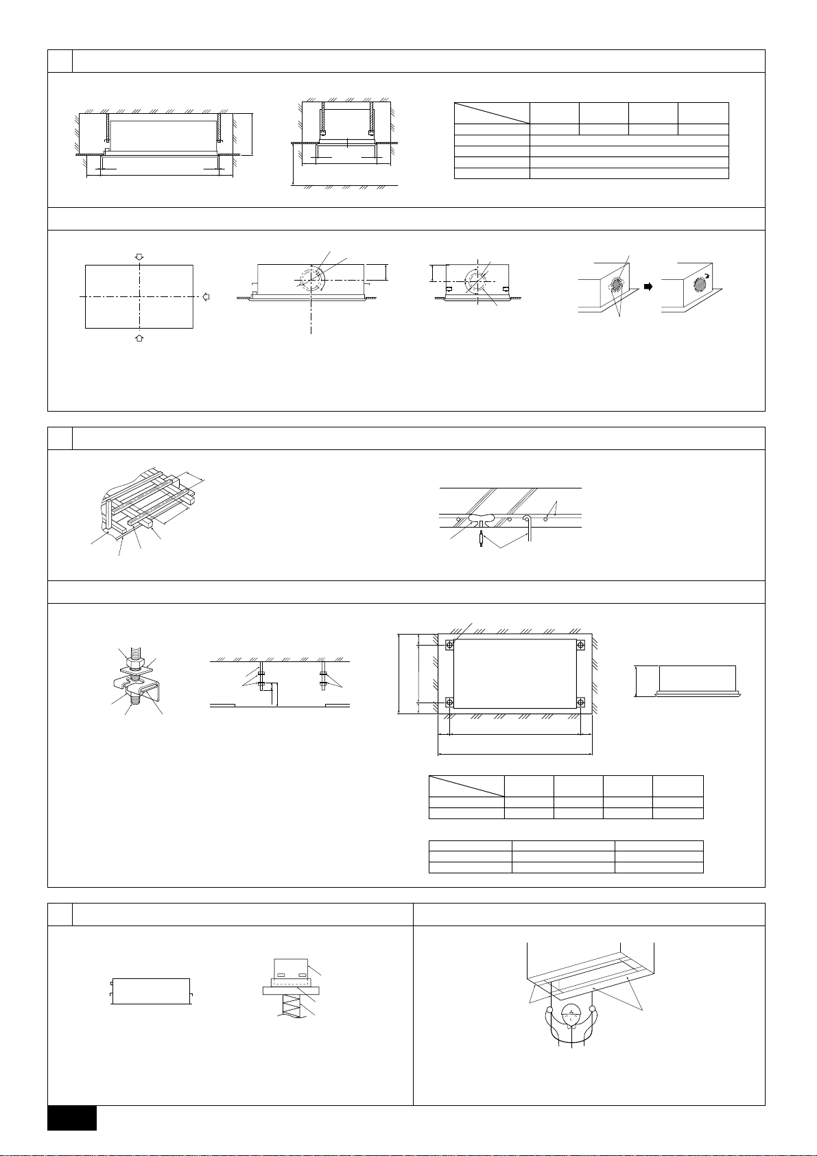
[Fig. 3.1.1]
3.1
Model name
E
670
D
C
D
C
A
D
C
D
B
C
A 1060 1300 1650 2000
B More than 1000
C More than 500
D Lap: 20
E 360
20 · 25 · 32 40 · 50 63 · 80 100 · 125
3.2
[Fig. 3.2.1]
A
D
A
• Knockouts are provided at each position as shown in the figure. Use them for your purposes when installing the unit.
A Split flow duct end connection B Split flow duct end connection (ø200 knockout on both sides)
C Fresh air intake (ø150 knockout) D Fresh air intake
E To be cut F 4-ø2.9 mounting hole
G 4-ø2.9 mounting hole
4
[Fig. 4.1.1] [Fig. 4.1.2]
A
D
B
E
A Ceiling board
B Edge beam
E
C
C Tie beam
D Square timber for hanging the air
conditioner
E Pitch
B
ø224
45°
90°
145
181
F
4.1
4.2
[Fig. 4.2.1]
D
90˚
90˚
C
ø172
G
E
H
F
G
F Insert: 100 to 150 kg
(1 piece) (field supply)
G M10 hanging bolt (field
supply)
H Reinforcement
H
A
A
A Nut B Washer (supplied with the unit body)
C Hanging bolt ø10 (M10 screw) D Ceiling hole dimensions
E Hanging bolt pitch F Hanging bolt
G Finished ceiling surface H Hanging bracket
B
630
F
B
C
B
D
G
50±10
A
550 4040
D
E
• α indicates a range of 0 to 15 mm.
Installation example For not sliding unit body For sliding unit body
5
[Fig. 5.1.1] [Fig. 5.2.1]
A
B
C
D
C
E
B 102102
D
A
Model name
A 1020 1260 1610 1960
B 816 1056 1406 1756
Dimension C 338 338+α (353 Max.)
Dimension D 143 143+ α
20 · 25 · 32 40 · 50 63 · 80 100 · 125
5.25.1
A Drain pipe side B Unit body
C Packing cap D Lifting machine
2
B Indoor unit’s bottom surface
(Surface to which a decorative panel is attached)
6
D
C
E
B
A
EF
C
20 ~ 80
GH
C
100 · 125
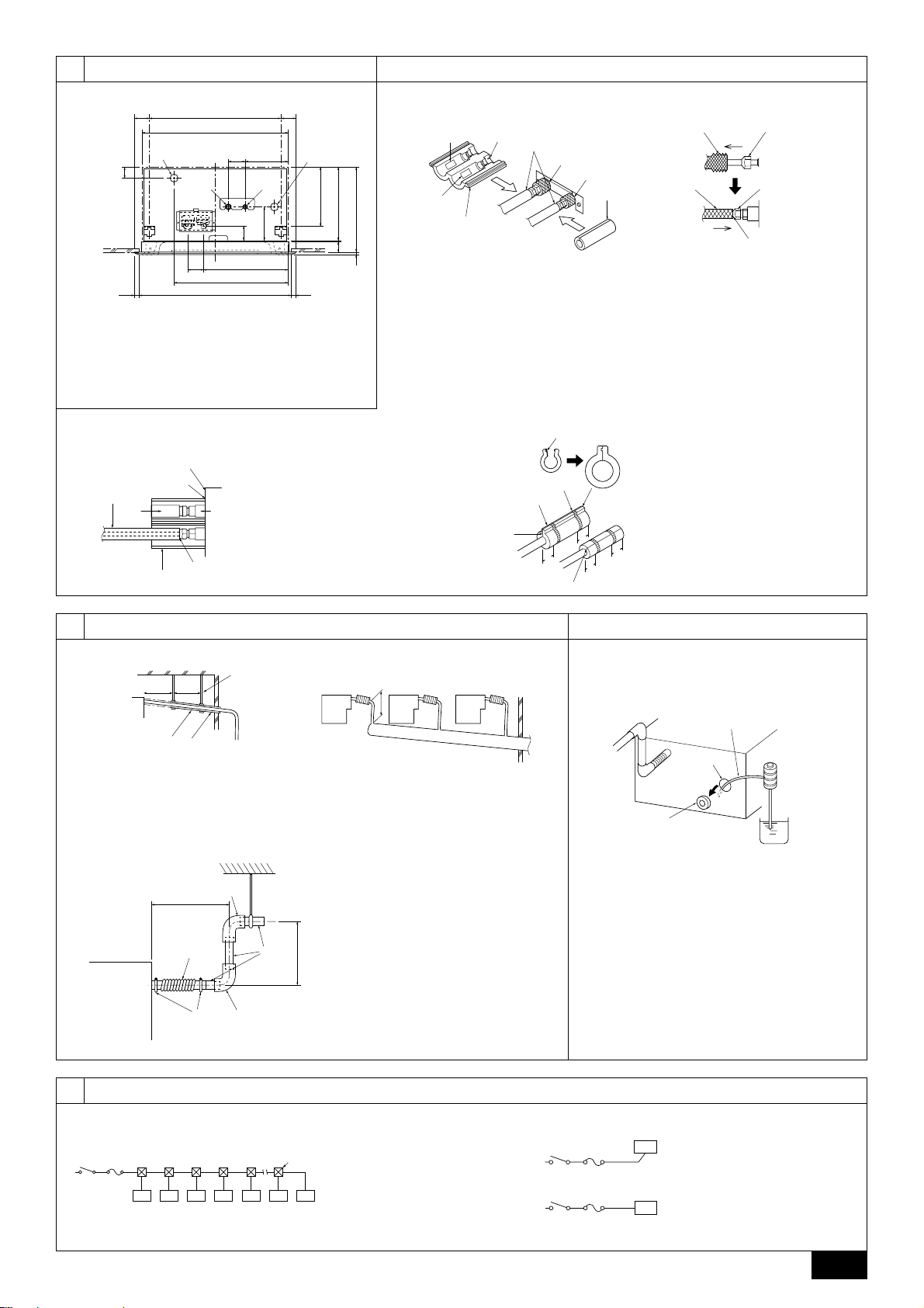
6.2
6.3
[Fig. 6.2.1] [Fig. 6.3.1]
60 60
38
20 20630
C
550
606
B
70 178
D
52
35070
476
A Refrigerant pipe (liquid pipe): HP
B Drain pipe
C Hanging bolt pitch
D Refrigerant pipe (gas pipe): LP
E Filling port
A
135
E
192
2903-1845
338-3538
C
[Fig. 6.3.2]
(figure showing the flare insulation)
C
B
A
DE
*2
G
A Field refrigerant piping
B There must be no gap.
C Unit body plate
D OUTER
F
E INNER
F Unit body
G Provided flare insulation (2)
A
B
*1
E
F
H
D
G
A “0-0 gas” mark B “INNER” mark
C “OUTER” mark D Flare insulation (2)
E Refrigerant piping (gas) F Refrigerant piping (liquid)
G Field refrigerant piping H Pipe insulation (1)
I Insulation material J Flare
K Pull in this direction. L Insulation material
M Flare N There must be no gap.
O Move to the original position.
[Fig. 6.3.3]
A
L
B
C
*4
20
20
20
20
A Tape (3)
B Fasten with tape.
C Provided tie band (4)
*3
JI
K
M
O
N
7
7.2
[Fig. 7.2.1] [Fig. 7.2.2] [Fig. 7.3.1]
A B
C
A
B
1
A: 25 cm
B: 1.5 – 2 m
A Downward pitch of more than 1/100
B Insulating material
C Metal brace
E
DDD
F
2
D Indoor unit
E Take as large as possible. About 10 cm
F Collected pipes
[Fig. 7.2.3]
I
H
C: 30 cm
G Drain hose (Accessory)
ss
s Be sure to use the supplied drain hose
J
G
C
D
K I
3
ss
(Accessory).
H Less than 300 mm
I Hard vinyl chloride 90° elbow (field supply)
J Hard vinyl chloride (VP-25) (field supply)
K Tie band (small) (Accessory)
7.3
A Insert the pump’s end 2 to 4 cm.
B Remove the polyethylene plug.
C About 1000 cc
D Water
E Filling port
8
8.1
[Fig. 8.1.1] [Fig. 8.1.2]
A Switch 16 A
AB
DE
CCCCCCC
B Overcurrent protection 16 A
C Indoor unit
D Total operating current be less
than 16 A
E Pull box
E Switch 16 A
F Overcurrent protection 16 A
G Switch 16 A
H Overcurrent protection 16 A
3
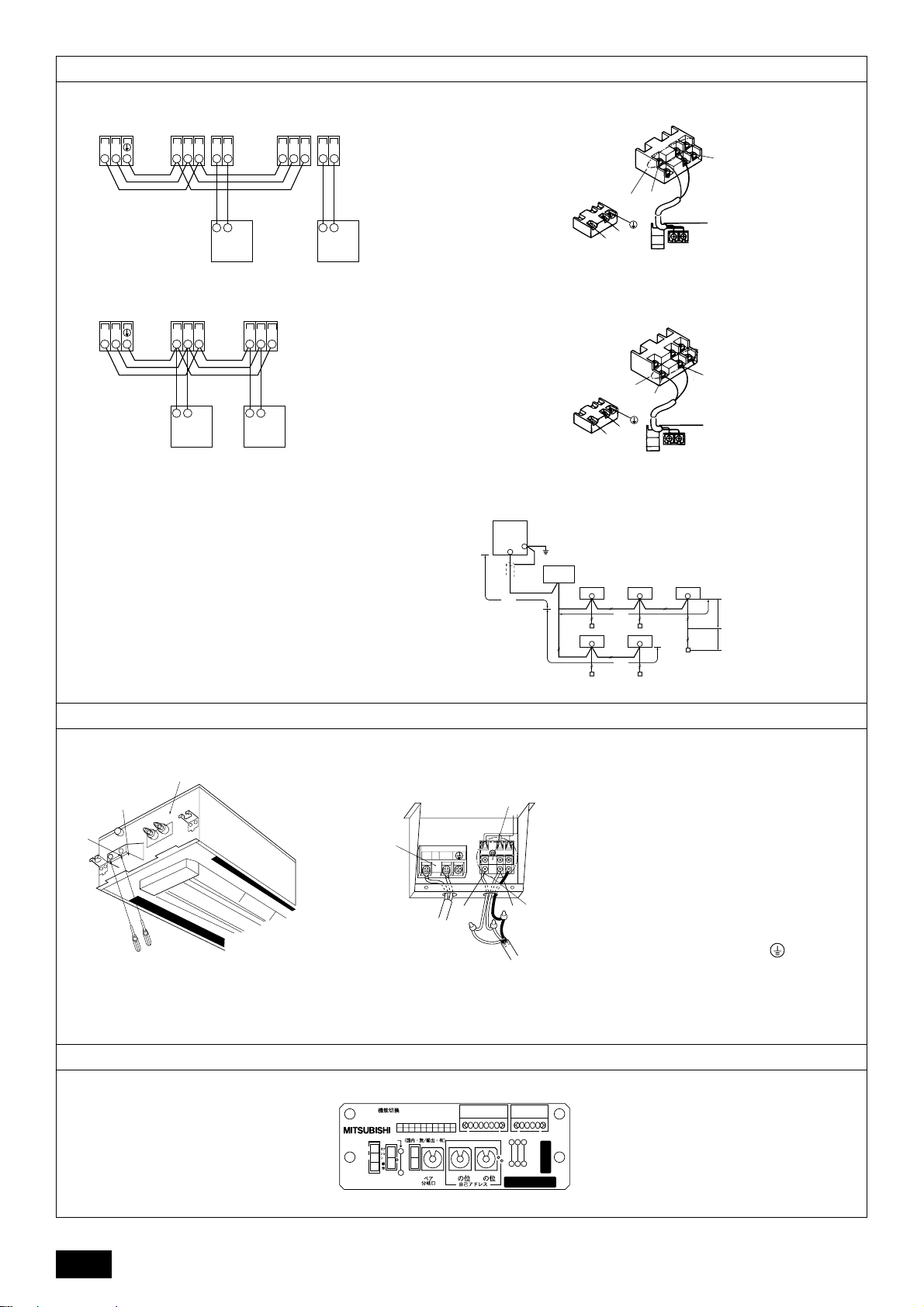
8.2
A
[Fig. 8.2.1]
B
M1M2 21
TB3
[Fig. 8.2.2]
B
M1M2
TB3
AA
SM1M2 SM1M2
TB5 TB15 TB5 TB15
C
21
C
AA
SM1M2 SM1M2
TB5 TB5
A Terminal block for indoor
transmission cable
B T erminal block for outdoor
transmission cable
C Remote controller
C
C
[Fig. 8.2.3]
[Fig. 8.2.4]
[Fig. 8.2.5]
G
L1
2
DC10~13V
AB
12
DC24~30V
C
12
(A, B)
K
A
C
M2
A
A Non-polarized
B Upper level (TB15)
C Remote Controller
D Lower level (TB5)
*2
L4
l
G Outdoor unit
H Earth
I BC controller
J Indoor unit
K Remote controller
L Non-polarized 2-wire
1
B
N
L
D
M1
N
L
*1
H
I
*3
JJJ
L2
KK
JJ
L
L3
KF
[Fig. 8.3.1] [Fig. 8.3.2]
<Viewed from bottom of the terminal bed box>
B
C
G
1
A Side frame
B Cover
C Cover securing screw (2 places)
[Fig. 8.4.1]
<Address board>
W254613G03
FP-AD-P
MADE IN JAPAN
ON
1
JP1
3
2
1
SWCSWA
8.3
D
Power Source
NL
F
21
M1 M2
2
SS
I
H
D Terminal bed for transmission cable
E Transmission cable
(T o terminal bed for remote controller , indoor unit
and BC controller)
F To single-phase power supply
G Terminal bed for power supply
H To terminal bed for outdoor transmission cable
(Use shielding earth cable on outdoor unit
side.)
I Non-polarity
J Network remote controller
K DC 24 to 30 V
8.4
SW1
CN828161
10
SW12
0
240V 220V
SW14
SW5
SW11
0
10
1
N0
N0
CN62
0
JP2
JP3
JP4
4
Contents
1. Safety precautions ...................................................................................... 5
1.1. Before installation and electric work .......................................... 5
1.2. Precautions for devices that use R407C refrigerant.................. 5
1.3. Before getting installed.............................................................. 6
1.4. Before getting installed (moved) - electrical work...................... 6
1.5. Before starting the test run ........................................................ 6
2. Indoor unit accessories ............................................................................... 6
3. Selecting an installation site ....................................................................... 6
3.1. Securing installation and service space .................................... 7
3.2. Split flow duct end connection - fresh air intake ........................ 7
3.3. Combining indoor units with outdoor units ................................ 7
4. Fixing hanging bolts .................................................................................... 7
4.1. Fixing hanging bolts .................................................................. 7
4.2. Ceiling hole and hanging bolt positions..................................... 7
5. Installing the unit ......................................................................................... 8
5.1. Hanging the unit body ............................................................... 8
1. Safety precautions
1.1. Before installation and electric work
s Before installing the unit, make sure you read all the “Safety
precautions”.
s The “Safety precautions” provide very important points re-
garding safety. Make sure you follow them.
Symbols used in the text
Warning:
Describes precautions that should be observed to prevent danger of injury
or death to the user.
Caution:
Describes precautions that should be observed to prevent damage to the
unit.
Symbols used in the illustrations
: Indicates an action that must be avoided.
: Indicates that important instructions must be followed.
: Indicates a part which must be grounded.
: Indicates that caution should be taken with rotating parts. (This symbol is
displayed on the main unit label.) <Color: yellow>
: Beware of electric shock (This symbol is displayed on the main unit label.)
<Color: yellow>
Warning:
Carefully read the labels affixed to the main unit.
Warning:
• Ask the dealer or an authorized technician to install the air conditioner.
- Improper installation by the user may result in water leakage , electric shock,
or fire.
• Install the air unit at a place that can withstand its weight.
- Inadequate strength may cause the unit to fall down, resulting in injuries.
• Use the specified cables for wiring. Make the connections securely so
that the outside force of the cable is not applied to the terminals.
- Inadequate connection and fastening may generate heat and cause a fire.
• Prepare for typhoons and other strong winds and earthquakes and install the unit at the specified place.
- Improper installation may cause the unit to topple and result in injury.
• Alwa ys use an air cleaner, humidifier, electric heater , and other accessories specified by Mitsubishi Electric.
- Ask an authorized technician to install the accessories. Improper installation
by the user may result in water leakage, electric shock, or fire.
• Never repair the unit. If the air conditioner must be repaired, consult the
dealer.
- If the unit is repaired improperly, water leakage, electric shock, or fire may
result.
• Do not touch the heat exchanger fins.
- Improper handling may result in injury.
• If refrigerant gas leaks during installation work, ventilate the room.
- If the refrigerant gas comes into contact with a flame, poisonous gases will
be released.
• Install the air conditioner according to this Installation Manual.
- If the unit is installed improperly, water leakage, electric shock, or fire may
result.
5.2. Confirming the unit’s position and fixing hanging bolts ............. 8
6. Refrigerant pipe and drain pipe specifications ............................................ 8
6.1. Refrigerant pipe and drain pipe specifications .......................... 8
6.2. Refrigerant pipe , drain pipe and filling port .............................. 8
6.3. Request for refrigerant piping connection ................................. 8
7. Connecting refrigerant pipes and drain pipes ............................................. 9
7.1. Refrigerant piping work ............................................................. 9
7.2. Drain piping work....................................................................... 9
7.3. Confirming drain discharge ....................................................... 9
8. Electrical wiring ......................................................................................... 10
8.1. Power supply wiring................................................................. 10
8.2. Connecting remote controller, indoor and outdoor
transmission cables................................................................. 11
8.3. Connecting electrical connections........................................... 11
8.4. Setting addresses.................................................................... 11
8.5. Sensing room temperature with the built-in sensor in
a remote controller .................................................................. 11
• Have all electric work done by a licensed electrician according to “Electric Facility Engineering Standard” and “Interior Wire Regulations”and
the instructions given in this manual and always use a special circuit.
- If the power source capacity is inadequate or electric work is performed im-
properly, electric shock and fire may result.
• Securely install the outdoor unit terminal cover (panel).
- If the terminal cover (panel) is not installed properly , dust or water may enter
the outdoor unit and fire or electric shock may result.
• When installing and moving the air conditioner to another site, do not
charge the it with a refrigerant different from the refrigerant (R407C or
R22) specified on the unit.
- If a different refrigerant or air is mixed with the original refrigerant, the refrig-
erant cycle may malfunction and the unit may be damaged.
• If the air conditioner is installed in a small room, measures must be taken
to prevent the refrigerant concentration from exceeding the safety limit
even if the refrigerant should leak.
- Consult the dealer regarding the appropriate measures to prevent the safety
limit from being exceeded. Should the refrigerant leak and cause the safety
limit to be exceeded, hazards due to lack of oxygen in the room could result.
• When moving and reinstalling the air conditioner, consult the dealer or
an authorized technician.
- If the air conditioner is installed improperly , water leakage , electric shock, or
fire may result.
• After completing installation work, make sure that refrigerant gas is not
leaking.
- If the refrigerant gas leaks and is exposed to a fan heater, stove, oven, or
other heat source, it may generate noxious gases.
• Do not reconstruct or change the settings of the protection devices.
- If the pressure switch, thermal switch, or other protection device is shorted
and operated forcibly, or parts other than those specified by Mitsubishi Electric are used, fire or explosion may result.
1.2. Precautions for devices that use R407C
refrigerant
Caution:
• Do not use the existing refrigerant piping.
- The old refrigerant and refrigerator oil in the existing piping contains a large
amount of chlorine which may cause the refrigerator oil of the new unit to
deteriorate.
• Use refrigerant piping made of C1220 (CU-DHP) phosphorus deoxidized
copper as specified in the JIS H3300 “Copper and copper allo y seamless
pipes and tubes”. In addition, be sure that the inner and outer surfaces of
the pipes are clean and free of hazardous sulphur , o xides, dust/dirt, shaving particles, oils, moisture, or any other contaminant.
- Contaminants on the inside of the refrigerant piping may cause the refriger-
ant residual oil to deteriorate.
• Store the piping to be used during installation indoors and keep both
ends of the piping sealed until just before brazing. (Store elbows and
other joints in a plastic bag.)
- If dust, dirt, or water enters the refrigerant cycle, deterioration of the oil and
compressor trouble may result.
• Use ester oil, ether oil or alkylbenz ene (small amount) as the refrigerator
oil to coat flares and flange connections.
- The refrigerator oil will degrade if it is mixed with a large amount of mineral
oil.
• Use liquid refrigerant to fill the system.
- If gas refrigerant is used to seal the system, the composition of the refriger-
ant in the cylinder will change and performance may drop.
GB
D
F
E
INL
PGRRUTR
5
• Do not use a refrigerant other than R407C.
- If another refrigerant (R22, etc.) is used, the chlorine in the refrigerant may
cause the refrigerator oil to deteriorate.
• Use a vacuum pump with a reverse flow check valve.
- The vacuum pump oil may flow back into the refrigerant cycle and cause the
refrigerator oil to deteriorate.
• Do not use the following tools that are used with conventional refrigerants.
(Gauge manifold, charge hose, gas leak detector , reverse flow chec k valve,
refrigerant charge base, vacuum gauge, refrigerant reco very equipment)
- If the conventional refrigerant and refrigerator oil are mixed in the R407C,
the refrigerant may deteriorated.
- If water is mixed in the R407C, the refrigerator oil may deteriorate.
- Since R407C does not contain any chlorine, gas leak detectors for conven-
tional refrigerants will not react to it.
• Do not use a charging cylinder.
- Using a charging cylinder may cause the refrigerant to deteriorate.
• Be especially careful when managing the tools.
- If dust, dirt, or water gets in the refrigerant cycle, the refrigerant may deterio-
rate.
1.3. Before getting installed
Caution:
• Do not install the unit where combustible gas may leak.
GB
- If the gas leaks and accumulates around the unit, an explosion may result.
• Do not use the air conditioner where food, pets, plants, precision instruments, or artwork are kept.
- The quality of the food, etc. may deteriorate.
• Do not use the air conditioner in special environments.
D
- Oil, steam, sulfuric smoke, etc. can significantly reduce the performance of
the air conditioner or damage its parts.
• When installing the unit in a hospital, communication station, or similar
place, provide sufficient protection against noise.
- The inverter equipment, private power generator, high-frequency medical
F
E
equipment, or radio communication equipment may cause the air conditioner
to operate erroneously, or fail to operate. On the other hand, the air conditioner may affect such equipment by creating noise that disturbs medical
treatment or image broadcasting.
• Do not install the unit on a structure that may cause leakage.
- When the room humidity exceeds 80 % or when the drain pipe is clogged,
condensation may drip from the indoor unit. P erform collective drainage w ork
together with the outdoor unit, as required.
• The indoor models should be installed the ceiling over than 2.5 m from
floor.
INL
1.4. Before getting installed (moved) - elec-
trical work
Caution:
• Ground the unit.
- Do not connect the ground wire to gas or water pipes, lightning rods, or
telephone ground lines. Improper grounding may result in electric shock.
• Install the power cable so that tension is not applied to the cable.
- Tension may cause the cable to break and generate heat and cause a fire.
• Install an leak circuit breaker, as required.
- If an leak circuit breaker is not installed, electric shock may result.
• Use power line cables of sufficient current carrying capacity and rating.
- Cables that are too small may leak, generate heat, and cause a fire.
• Use only a circuit breaker and fuse of the specified capacity.
- A fuse or circuit breaker of a larger capacity or a steel or copper wire may
result in a general unit failure or fire.
• Do not wash the air conditioner units.
- Washing them may cause an electric shock.
• Be careful that the installation base is not damaged by long use.
- If the damage is left uncorrected, the unit may fall and cause personal injury
or property damage.
• Install the drain piping according to this Installation Manual to ensure
proper drainage. Wrap thermal insulation around the pipes to prevent
condensation.
- Improper drain piping may cause water leakage and damage to furniture
and other possessions.
• Be very careful about product transportation.
- Only one person should not carry the product if it weighs more than 20 kg.
- Some products use PP bands for packaging. Do not use an y PP bands f or a
means of transportation. It is dangerous.
- Do not touch the heat exchanger fins. Doing so may cut your fingers.
- When transporting the outdoor unit, suspend it at the specified positions on
the unit base. Also support the outdoor unit at four points so that it cannot
slip sideways.
• Safely dispose of the packing materials.
- Packing materials, such as nails and other metal or wooden parts, may cause
stabs or other injuries.
- Tear apart and throw away plastic packaging bags so that children will not
play with them. If children play with a plastic bag which was not torn apart,
they face the risk of suffocation.
1.5. Before starting the test run
Caution:
• Turn on the power at least 12 hours before starting operation.
- Starting operation immediately after turning on the main power switch can
result in severe damage to internal parts. Keep the power switch turned on
during the operational season.
• Do not touch the switches with wet fingers.
- Touching a switch with wet fingers can cause electric shock.
• Do not touch the refrigerant pipes during and immediately after operation.
- During and immediately after operation, the refrigerant pipes are may be hot
and may be cold, depending on the condition of the refrigerant flowing through
the refrigerant piping, compressor, and other refrigerant cycle parts. Your
hands may suffer burns or frostbite if you touch the refrigerant pipes.
• Do not operate the air conditioner with the panels and guards removed.
- Rotating, hot, or high-voltage parts can cause injuries.
• Do not turn off the power immediately after stopping operation.
- Always wait at least five minutes before turning off the power. Otherwise,
water leakage and trouble may occur.
2. Indoor unit accessories
PGRRUTR
The unit is provided with the following accessories:
Part No. Accessories Qty Place to Set
1 Insulation pipe (small) 1
2 Insulating cover 1
3 Tie band (large) 6
4 Drain hose 1
5 Washer 8
On the body frame casing
3. Selecting an installation site
• Select a location so that air can be blown into all corners of the room.
• Avoid locations exposed to outside air.
• Select a location free of obstructions to the airflow in and out of the unit.
• Avoid locations exposed to steam or oil vapour.
• Avoid locations where combustible gas may leak, settle or be generated.
• Av oid installation near machines emitting high-frequency wav es (high-frequency
welders, etc.).
• Avoid locations where the airflow is directed at a fire alarm sensor. (Hot air
could trigger the alarm during the heating operation.)
6
Part No. Accessories Qty Place to Set
6 Tie band (small) 2
7 Insulation pipe (large) 1
8 Connector for drain pump test 1
• Avoid places where acidic solutions are frequently handled.
• Avoid places where sulphur-based or other sprays are frequently used.
On the body frame casing
Warning:
Install the indoor unit on a ceiling strong enough to sustain its weight.
If the ceiling lacks strength, it may cause the unit to fall do wn, resulting in an
injury.
 Loading...