

Mitsubishi Electric PKFY-P·VAM-E, PMFY-P·VBM-E, PLFY-P·VAM-E, PFFY-P·VKM-E, PKFY-P·VGM-E Operation Manual
...
Air-Conditioners For Building Application
INDOOR UNIT
PKFY-P·VAM-E / PKFY-P·VGM-E
PKFY-P·VFM-E / PMFY-P·VBM-E
PCFY-P·VGM-E / PLFY-P·VAM-E
PFFY-P·VKM-E
OPERATION MANUAL
For safe and correct use, please read this operation manual thoroughly before operating the air-conditioner unit.
BEDIENUNGSHANDBUCH
Zum sicheren und einwandfreien Gebrauch der Klimaanlage dieses Bedienungshandbuch vor Inbetriebnahme
gründlich durchlesen.
MANUEL D’UTILISATION
Pour une utilisation correcte sans risques, veuillez lire le manuel d’utilisation en entier avant de vous servir du
climatiseur.
BEDIENINGSHANDLEIDING
Voor een veilig en juist gebruik moet u deze bedieningshandleiding grondig doorlezen voordat u de
airconditioner gebruikt.
MANUAL DE INSTRUCCIONES
Lea este manual de instrucciones hasta el final antes de poner en marcha la unidad de aire acondicionado
para garantizar un uso seguro y correcto.
ISTRUZIONI DI FUNZIONAMENTO
Leggere attentamente questi istruzioni di funzionamento prima di avviare l’unità, per un uso corretto e sicuro
della stessa.
E°XEIPI¢IO O¢H°IøN XPH™Eø™
°И· ·ЫК¿ПВИ· О·И ЫˆЫЩ‹ ¯Ъ‹ЫЛ, ·Ъ·О·ПВ›ЫЩВ ‰И·‚¿ЫВЩВ ЪФЫВ¯ЩИО¿ ·˘Щfi ЩФ ВБ¯ВИЪ›‰ИФ ¯Ъ‹ЫВˆ˜ ЪИУ ı¤ЫВЩВ ЫВ
ПВИЩФ˘ЪБ›· ЩЛ МФУ¿‰· ОПИМ·ЩИЫМФ‡.
MANUAL DE OPERAÇÃO
Para segurança e utilização correctas, leia atentamente o manual de operação antes de pôr a funcionar a
unidade de ar condicionado.
FOR USER
FÜR BENUTZER
POUR L’UTILISATEUR
VOOR DE GEBRUIKER
Nederlands
PARA EL USUARIO
PER L’UTENTE
°π∞ ∆√¡ Ã∏™∆∏
PARA O UTILIZADOR
Português
English
Deutsch
Français
Español
Italiano
∂ППЛУИО¿
Iflletme Elkitab›
Emniyetli ve do¤ru biçimde nas›l kullan›laca¤›n› ö¤renmek için lütfen klima cihaz›n› iflletmeden önce bu
elkitab›n› dikkatle okuyunuz.
РУКОВОДСТВО ПО ЭКСПЛУАТАЦИИ
Для обеспечения правильного и безопасного использования следует ознакомиться с инструкциями,
указанными в данном руководстве по эксплуатации, тщательным образом до того, как приступать к
использованию кондиционера.
KULLANICI ‹Ç‹N
Türkçe
ДЛЯ ПОЛЬЗОВАТЕЛЯ
Русский
( )
Contents
1. Safety Precautions ................................................................ 2
2. Parts Names.......................................................................... 3
3. Screen Configuration............................................................. 5
4. Setting the Day of the Week and Time .................................. 5
5. Operation............................................................................... 5
6. Timer ..................................................................................... 7
1. Safety Precautions
s Before installing the unit, make sure you read all the
“Safety Precautions”.
s The “Safety Precautions” provide very important points
regarding safety. Make sure you follow them.
s Please report to or take consent by the supply author-
ity before connection to the system.
Warning:
• The unit must not be installed by the user. Ask the dealer or an
authorized company to install the unit. If the unit is installed improperly, water leakage, electric shock or fire may result.
• Do not stand on, or place any items on the unit.
• Do not splash water over the unit and do not touch the unit with
wet hands. An electric shock may result.
• Do not spray combustible gas close to the unit. Fire may result.
• Do not place a gas heater or any other open-flame appliance where
it will be exposed to the air discharged from the unit. Incomplete
combustion may result.
• Do not remove the front panel or the fan guard from the outdoor
unit when it is running.
• Never repair the unit or transfer it to another site by yourself.
Caution:
• Do not use any sharp object to push the buttons, as this may damage the remote controller.
• Never block or cover the indoor or outdoor unit’s intakes or outlets.
• Never wipe the remote controller with benzene, thinner chemical
rags, etc.
• Do not operate the unit for a long time in high humidity, e.g. leaving
a door or window open. In the cooling mode, if the unit is operated
in a room with high humidity (80% RH or more) for a long time,
water condensed in the air conditioner may drop and wet or damage furniture, etc.
7. Other Functions ................................................................... 10
8. Function Selection ............................................................... 11
9. Care and Cleaning .............................................................. 15
10. Trouble Shooting................................................................ 16
11. Specifications .................................................................... 19
Symbols used in the text
Warning:
Describes precautions that should be observed to prevent danger of
injury or death to the user.
Caution:
Describes precautions that should be observed to prevent damage
to the unit.
Symbols used in the illustrations
: Indicates a part which must be grounded.
• When you notice exceptionally abnormal noise or vibration, stop
operation, turn off the power switch, and contact your dealer.
• Never insert fingers, sticks etc. into the intakes or outlets.
• If you detect odd smells, stop using the unit, turn off the power
switch and consult your dealer. Otherwise, a breakdown, electric
shock or fire may result.
• This air conditioner is NOT intended for use by children or infirm
persons without supervision.
• Young children must be supervised to ensure that they do not play
with the air conditioner.
• If the refrigeration gas blows out or leaks, stop the operation of the
air conditioner, thoroughly ventilate the room, and contact your
dealer.
• Do not touch the upper air outlet vane or the lower air outlet damper
during operation. Otherwise, condensation may form and the unit
may stop operating.
Disposing of the unit
When you need to dispose of the unit, consult your dealer.
2
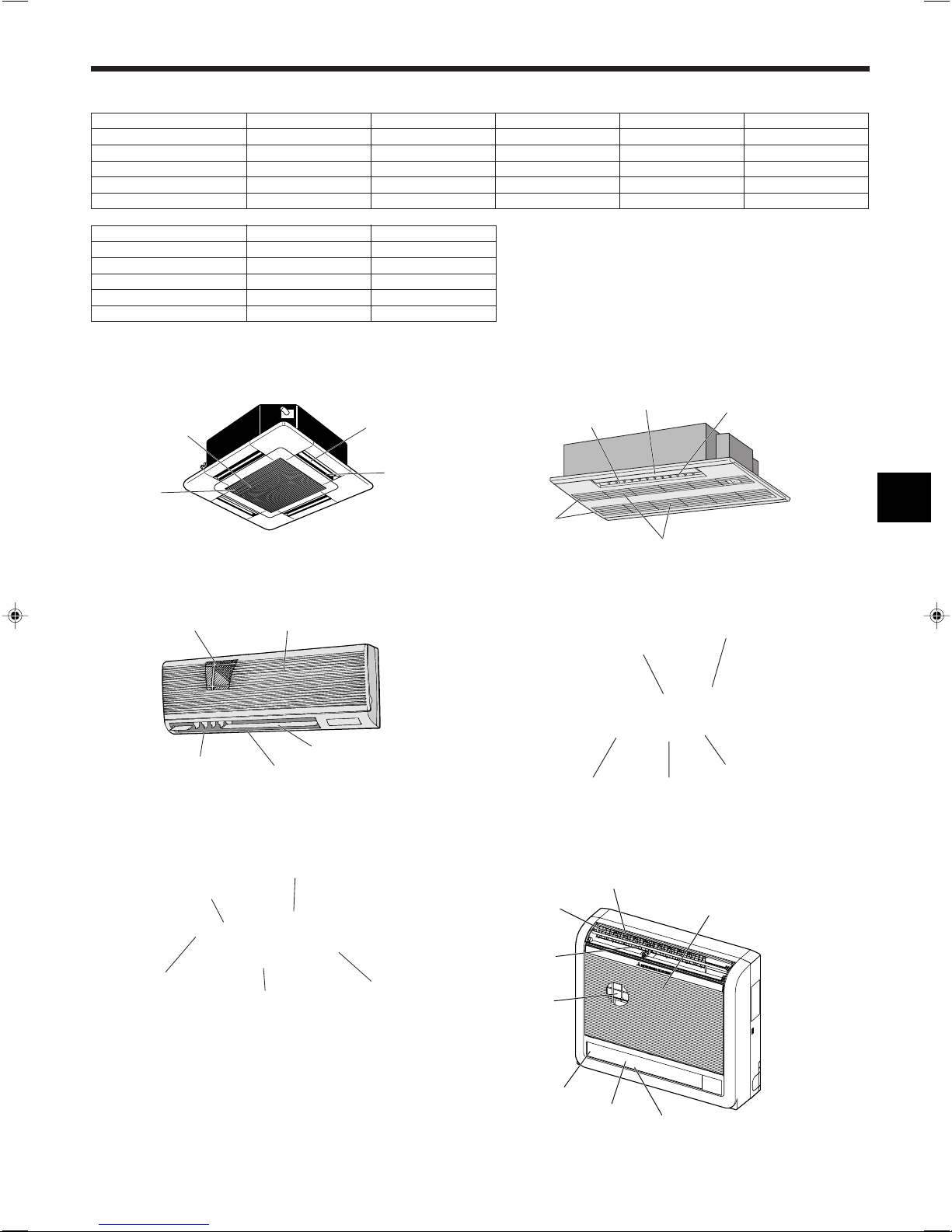
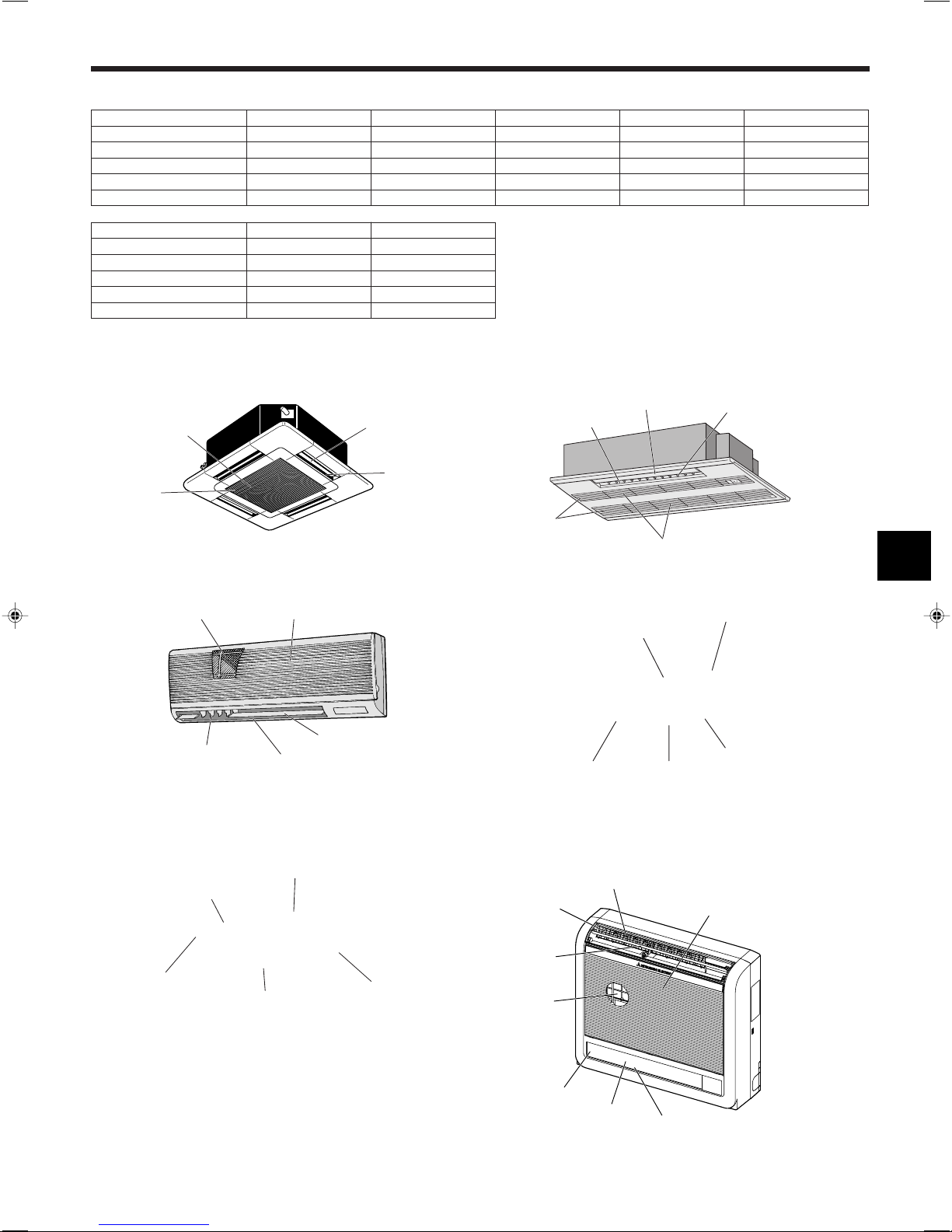
2. Parts Names
■ Indoor Unit
PLFY-P·VAM-E PKFY-P·VAM-E PKFY-P·VGM-E PKFY-P·VFM-E PCFY-P·VGM-E
Fan steps 4 steps 4 steps 4 steps 2 steps 4 steps
Vane Auto with swing Auto with swing Auto with swing Auto with swing Auto with swing
Louver – Manual Manual Manual Manual
Filter Long-life Normal Normal Normal Long-life
Filter cleaning indication 2,500 hr 100 hr 100 hr 100 hr 2,500 hr
PMFY-P·VBM-E PFFY-P·VKM-E
Fan steps 4 steps 4 steps
Vane Auto with swing Auto with swing
Louver Manual Manual
Filter Normal Normal
Filter cleaning indication 100 hr 100 hr
■ PLFY-P·VAM-E
4-way Ceiling Cassette
Filter
Air intake
■ PKFY-P·VAM-E/PKFY-P·VGM-E
Wall Mounted
Filter
Louver
Air intake
Air outlet
Vane
Vane
Air outlet
■ PMFY-P·VBM-E
1-way Ceiling Cassette
Air outlet
Filter
■ PKFY-P·VFM-E
Wall Mounted
Louver
Vane
Air inlet
Filter
Louver
Air intake
Vane
Air outlet
■ PCFY-P·VGM-E
Ceiling Suspended
Louver
Air outlet
Vane
Air intake
Filter
■ PFFY-P·VKM-E
Floor Standing
Air outlet
Vane
Filter
Damper
Louver
Air outlet
Air inlet
Louver
3
PAR-21MAA
ON/OFF
FILTER
CHECK
OPERATION
CLEAR
TEST
TEMP.
MENU
BACK DAY
MONITOR/SET
CLOCK
ON/OFF
2. Parts Names
■ Wired Remote-Controller
Display Section
For purposes of this explanation,
all parts of the display are shown
as lit. During actual operation, only
the relevant items will be lit.
Identifies the current operation
Shows the operating mode, etc.
* Multi-language display is sup-
ported.
“Centrally Controlled” indicator
Indicates that operation of the remote controller has been prohibited by a master controller.
“Timer is Off” indicator
Indicates that the timer is off.
Temperature Setting
Shows the target temperature.
Operation Section
Set Temperature buttons
Down
Up
Timer Menu button
(Monitor/Set button)
Mode button (Return button)
Day-of-Week
Shows the current day of the week.
Time/Timer Display
Shows the current time, unless the simple or Auto Off
timer is set.
If the simple or Auto Off timer is set, shows the time
remaining.
TIME SUN MON TUE WED THU FRI SAT
TIMER
AFTER
ERROR CODE
˚F˚C
˚F˚C
ONLY1Hr.
Up/Down Air Direction indicator
The indicator shows the direction
of the airflow.
“One Hour Only” indicator
Displayed if the airflow is set to weak and
downward during COOL or DRY mode.
(Operation varies according to model.)
The indicator goes off after one hour, at
which time the airflow direction also
changes.
Room Temperature display
Shows the room temperature. The room
temperature display range is 8–39°C.
The display flashes if the temperature
is less than 8 °C or 39 °C or more.
Louver display
Indicates the action of the swing louver.
Does not appear if the louver is stationary.
Indicates that the power is on.
ON
Hr
OFF
AFTER
FUNCTION
FILTER
WEEKLY
SIMPLE
AUTO OFF
(Power On indicator)
“Sensor” indication
Displayed when the remote controller
sensor is used.
“Locked” indicator
Indicates that remote controller buttons have been locked.
“Clean The Filter” indicator
Comes on when it is time to clean the
filter.
Timer indicators
The indicator comes on if the corresponding timer is set.
Fan Speed indicator
Shows the selected fan speed.
Ventilation indicator
Appears when the unit is running in
Ventilation mode.
ON/OFF button
Fan Speed button
Filter button
(<Enter> button)
Set Time buttons
Back
Ahead
Timer On/Off button
(Set Day button)
Opening the
door.
Note:
● “PLEASE WAIT” message
This message is displayed for approximately 3 minutes when power is supplied to the indoor unit or when the unit is recovering from a power failure.
● Operation mode flashing display
When multiple indoor units are connected to a single outdoor unit and an operation mode is selected for one indoor unit that is different from the
current operation mode of another indoor unit, the operation mode display flashes. Select the same operation mode of the other indoor unit.
● “NOT AVAILABLE” message
This message is displayed if a button is pressed to operate a function that the indoor unit does not have.
When the same remote controller is used to operate multiple indoor units, this message is displayed if the main indoor unit is not equipped with the
selected function.
● Room temperature display
The indoor unit temperature sensors or the remote controller temperature sensor can be selected to measure the room temperature. The indoor unit
temperature sensors are the initial setting. When the indoor unit temperature sensors are selected to measure the room temperature, the room
temperature measured at the main indoor unit is displayed on the remote controller that operates multiple indoor units.
4
Built-in temperature sensor
Test Run button
Check button (Clear button)
Airflow Up/Down button
Louver button
( Operation button)
To preceding operation
number.
Ventilation button
( Operation button)
To next operation number.
˚C
˚C
TIME SUN
PAR-21MAA
ON/OFF
FILTER
CHECK
OPERATION
CLEAR
TEST
TEMP.
MENU
BACK DAY
MONITOR/SET
CLOCK
ON/OFF
2
4
9
1
A
TIME SUN
2
3
4
˚C
˚C
PAR-21MAA
ON/OFF
FILTER
CHECK
OPERATION
CLEAR
TEST
TEMP.
MENU
BACK DAY
MONITOR/SET
CLOCK
ON/OFF
2
7
2
3
3
8
6
4
5
8
7
1
1
5
6
˚F˚C
TIMER
MON
OFF
WEEKLY
SUN MON TUE WED THU FRI SAT
WEEKLY
˚F˚C
˚C
TIME SUN
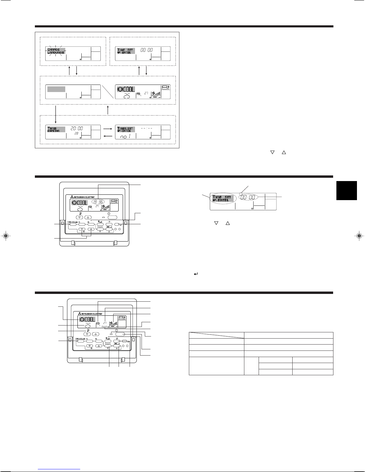
3. Screen Configuration
Function Selection of remote controller
ADC
Standard Control Screens
OFF ON
BC
Timer Monitor Timer Setup
B
Set Day/Time
4. Setting the Day of the Week and Time
Day of the Week &
Time display
<Screen Types>
For details on setting the language for the remote controller display, refer
to section 8. Function Selection.
The initial language setting is English.
● Function Selection of remote controller:
Set the functions and ranges available to the re-
mote controller (timer functions, operating restrictions, etc.)
● Set Day/Time: Set the current day of the week or time.
● Standard Control Screens:
View and set the air conditioning system’s oper-
ating status
● Timer Monitor: View the currently set timer (weekly timer, sim-
ple timer, or Auto Off timer)
● Timer Setup: Set the operation of any of the timers (weekly
timer, simple timer, or Auto Off timer).
<How to change the screen>
A :Hold down both the Mode button and the Timer On/Off button for 2
seconds.
B :Press the Timer Menu button.
C :Press the Mode (Return) button.
D :Press either of the Set Time buttons ( or ).
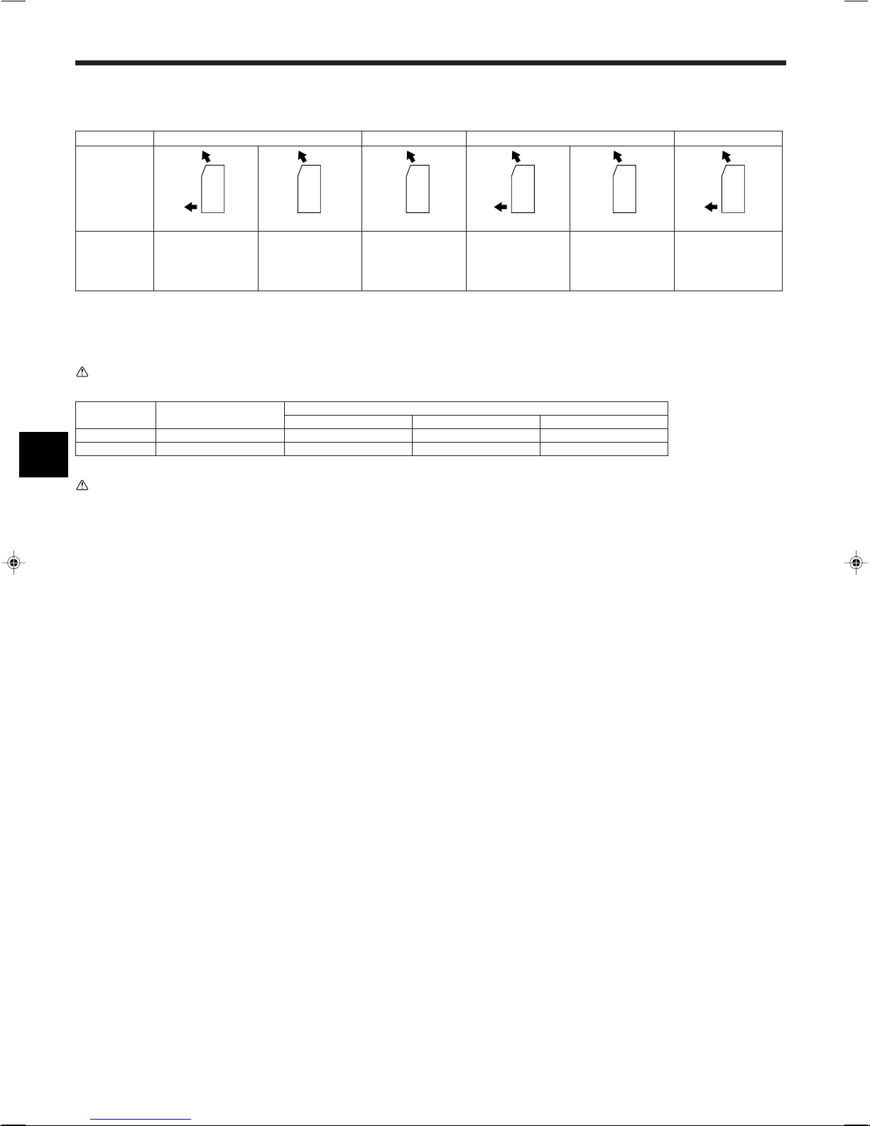
Day of the Week Setting
Time Setting
Note:
The day and time will not appear if clock use has been disabled at Function
Selection of remote controller.
5. Operation
1. Press the or Set Time button A to show display 2.
2. Press the Timer On/Off (Set Day) button 9 to set the day.
*Each press advances the day shown at 3 : Sun → Mon → ... → Fri →
Sat.
3. Press the appropriate Set Time button A as necessary to set the time.
*As you hold the button down, the time (at 4) will increment first in
minute intervals, then in ten-minute intervals, and then in one-hour intervals.
4. After making the appropriate settings at Steps 2 and 3, press the Filter
button 4 to lock in the values.
5.1. Turning ON/OFF
<To Start Operation>
■ Press the ON/OFF button 1.
• The ON lamp 1 and the display area come on.
Note:
● When the unit is restarted, initial settings are as follows.
Remote Controller settings
Mode
Temperature setting
Fan speed
Airflow up/down
Last operation mode
Last set temperature
Last set fan speed
COOL or DRY
Mode HEAT
FAN
Horiz. outlet
Last setting
Horiz. outlet
5
5. Operation
1234
123 4
123 4
<To Stop Operation>
■ Press the ON/OFF button 1 again.
• The ON lamp 1 and the display area go dark.
Note:
Even if you press the ON/OFF button immediately after shutting down the operation is progress, the air conditioner will not start for about three minutes.
This is to prevent the internal components from being damaged.
5.2. Mode select
■ Press the operation mode ( ) button 2 and select the opera-
tion mode 2.
s
Cooling mode
Drying mode
Fan mode
Heating mode
Automatic (cooling/heating) mode
Automatic operation
■ According to a set temperature, cooling operation starts if the room temperature is too hot and heating operation starts if the room temperature
is too cold.
■ During automatic operation, if the room temperature changes and remains 1.5 °C or more above the set temperature for 3 minutes, the air
conditioner switches to cooling mode. In the same way, if the room temperature remains 1.5 °C or more below the set temperature for 3 minutes, the air conditioner switches to heating mode.
Cooling mode
3 minutes (switches from
heating to cooling)
Set temperature +1.5°C
5.4. Fan speed setting
■ Press the Fan Speed button 5 as many times as necessary while the
system is running.
• Each press changes the force. The currently selected speed is shown
at 5.
• The change sequence, and the available settings, are as follows.
FAN SPEED
4-speed
model
2-speed
model
Note:
● The number of available fan speeds depends on the type of unit connected.
Note also that some units do not provide an “Auto” setting.
● In the following cases, the actual fan speed generated by the unit will differ
from the speed shown the remote controller display.
1. While the display is showing “STAND BY” or “DEFROST”.
2. When the temperature of the heat exchanger is low in the heating mode.
(e.g. immediately after heating operation starts)
3. In HEAT mode, when room temperature is higher than the temperature
setting.
4. When the unit is in DRY mode.
Speed 1 Speed 2 Speed 3 Speed 4
Display
5.5. Airflow direction setting
<To Change the Airflow’s Up/Down Direction>
■ With the unit running, press the Airflow Up/Down button 6 as necessary.
• Each press changes the direction. The current direction is shown at 6.
• The change sequence, and the available settings, are as follows.
Set temperature
Set temperature -1.5°C
3 minutes (switches
from cooling to heating )
■ Because the room temperature is automatically adjusted in order to
maintain a fixed effective temperature, cooling operation is performed a
few degrees warmer and heating operation is performed a few degrees
cooler than the set room temperature once the temperature is reached
(automatic energy-saving operation).
5.3. Temperature setting
ss
sTo decrease the room temperature:
ss
Press button 3 to set the desired temperature.
The selected temperature is displayed 3.
ss
sTo increase the room temperature:
ss
Press button 3 to set the desired temperature.
The selected temperature is displayed 3.
• Available temperature ranges are as follows:
Cooling/Drying: 19 - 30 °C
Heating: 17 - 28 °C
Automatic: 19 - 28 °C
• The display flashes either 8 °C - 39 °C to inform you if the room temperature is lower or higher than the displayed temperature.
Display
(Horiz.) Swing
* Note that during swing operation, the directional indication on the
screen does not change in sync with the directional vanes on the unit.
* Some models do not support directional settings.
Note:
● Available directions depend on the type of unit connected. Note also that
some units do not provide an “Auto” setting.
● In the following cases, the actual air direction will differ from the direction
indicated on the remote controller display.
1. While the display is showing “STAND BY” or “DEFROST”.
2. Immediately after starting heater mode (while the system is waiting for
the mode change to take effect).
3. In heat mode, when room temperature is higher than the temperature set-
ting.
(For PFFY-P·VKM series)
● For the PFFY-P·VKM series, the airflow direction displayed on the remote
controller is different from the actual airflow direction. Refer to the following
table.
Display
Actual
(Horiz.) Swing
(Horiz.) Swing
6
● The airflow direction for the lower air outlet damper cannot be set. The airflow direction is automatically controlled by a computer.
˚C
SUN
ON
WEEKLY
PAR-21MAA
ON/OFF
FILTER
CHECK
OPERATION
CLEAR
TEST
TEMP.
MENU
BACK DAY
MONITOR/SET
CLOCK
ON/OFF
2
42 3
A9 78
0
4
1
3
B
1
5. Operation
˚C
SUN
ON
WEEKLY
6
7
5
<To Change the Right/Left Air Direction>
■ Press the louver button 7 as necessary.
• The louver image 7 appears.
Each press of the button switches the setting as follows.
No display
(Stop)
(ON) (OFF)
During swing operation, the arrow display move to the left and right.
5.6. Ventillation
ss
sFor LOSSNAY combination
ss
5.6.1. For Wired Remote-controller
● To run the ventilator together with the indoor unit:
■ Press the ON/OFF button 1.
• The Vent indication appears on the screen (at 8). The ventilator will
now automatically operate whenever the indoor unit is running.
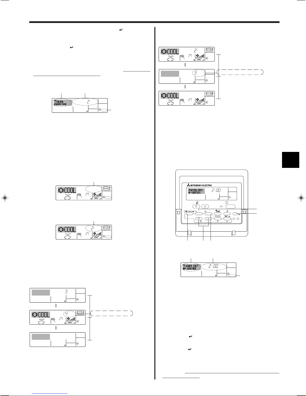
6. Timer
6.1. For Wired Remote-controller
You can use Function Selection of remote controller to select which of
three types of timer to use: 1 Weekly timer, 2 Simple timer, or 3 Auto Off
timer.
6.1.1. Weekly Timer
■ The weekly timer can be used to set up to eight operations for each day
of the week.
• Each operation may consist of any of the following: ON/OFF time
together with a temperature setting, or ON/OFF time only, or temperature setting only.
• When the current time reaches a time set at this timer, the air
conditioner carries out the action set by the timer.
■ Time setting resolution for this timer is 1 minute.
Note:
*1. Weekly Timer/Simple Timer/Auto Off Timer cannot be used at the same time.
*2. The weekly timer will not operate when any of the following conditions is in
effect.
The timer feature is off; the system is in an malfunction state; a test run is
in progress; the remote controller is undergoing self-check or remote controller check; the user is in the process of setting a function; the user is in
the process of setting the timer; the user is in the process of setting the
current day of the week or time; the system is under central control. (Specifically, the system will not carry out operations (unit on, unit off, or temperature setting) that are prohibited during these conditions.)
Operation No.
Day Setting
● To run the ventilator only when the indoor unit is off:
■ Press the Ventilation button 8 while the indoor unit is off.
• The On lamp (at 1) and the Vent indication (at 8) come on.
● To change the ventilator force:
■ Press the Ventilation button 8 as necessary.
• Each press toggles the setting, as shown below.
▲
▲
▲
No display
(Stop)
(Low) (High)
Note:
● With some model configurations, the fan on the indoor unit may come on
even when you set the ventilator to run independently.
(OFF)
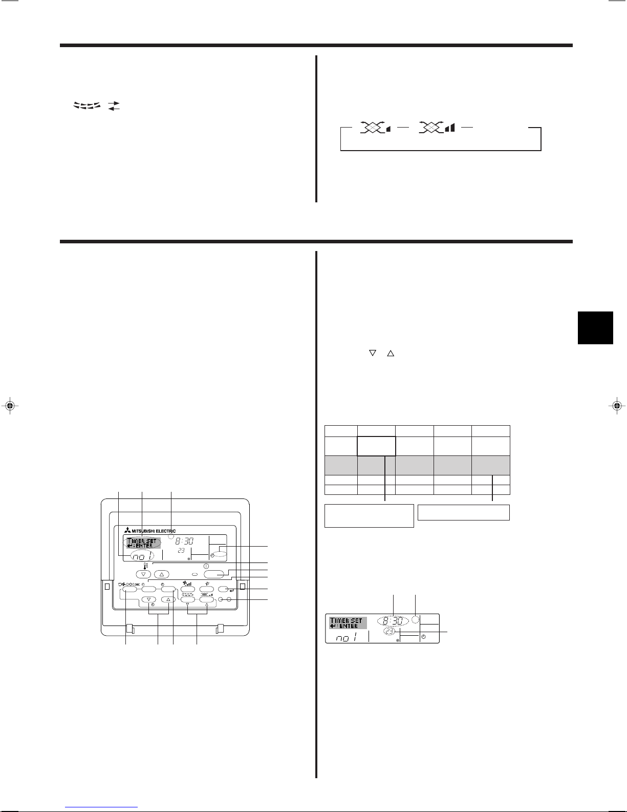
<How to Set the Weekly Timer>
1. Be sure that you are at a standard control screen, and that the weekly
timer indicator 1 is shown in the display.
2. Press the Timer Menu button B, so that the “Set Up” appears on the
screen (at 2). (Note that each press of the button toggles the display
between “Set Up” and “Monitor”.)
3. Press the Timer On/Off (Set Day) button 9 to set the day. Each press
advances the display at 3 to the next setting, in the following sequence:
“Sun Mon Tues Wed Thurs Fri Sat” → “Sun” → ... → “Fri” → “Sat” → “Sun
Mon Tues Wed Thurs Fri Sat”...
4. Press the or Operation button (7 or 8) as necessary to select the
appropriate operation number (1 to 8) 4.
* Your inputs at Steps 3 and 4 will select one of the cells from the matrix
illustrated below.
(The remote-controller display at left shows how the display would
appear when setting Operation 1 for Sunday to the values indicated
below.)
Setup Matrix
Op No. Sunday Monday … Saturday
• 8:30
• ON
No. 1
• 23 °C
• 10:00
No. 2
• OFF
…
No. 8
<Operation 1 settings for Sunday>
Start the air conditioner at 8:30, with
the temperature set to 23 °C.
Note:
By setting the day to “Sun Mon Tues Wed Thurs Fri Sat”, you can set the same
operation to be carried out at the same time every day.
(Example: Operation 2 above, which is the same for all days of the week.)
• 10:00
• OFF
▲
• 10:00
• OFF
• 10:00
• OFF
▲
<Operation 2 settings for every day>
Turn off the air conditioner at 10:00.
<Setting the Weekly Timer>
Shows the time
setting
Shows the selected operation (ON or OFF)
* Does not appear if operation is not set.
Shows the temperature setting
* Does not appear if temperature is not
set.
5. Press the appropriate Set Time button A as necessary to set the de-
sired time (at 5).
* As you hold the button down, the time first increments in minute inter-
vals, then in ten-minute intervals, and then in one-hour intervals.
6. Press the ON/OFF button 1 to select the desired operation (ON or
OFF), at 6.
* Each press changes the next setting, in the following sequence: No
display (no setting) → “ON” → “OFF”
7
ONHr
AFTER
SIMPLE
PAR-21MAA
ON/OFF
FILTER
CHECK
OPERATION
CLEAR
TEST
TEMP.
MENU
BACK DAY
MONITOR/SET
CLOCK
ON/OFF
2A9
0
4
1
B
ONHr
AFTER
SIMPLE
4
1
3
2
˚C
TIMER
SUN
ON
OFF
WEEKLY
1
9
8
˚C
˚C
TIME SUN
WEEKLY
0
˚C
˚C
TIME SUN
WEEKLY
0
6. Timer
7. Press the appropriate Set Temperature button 3 to set the desired
temperature (at 7).
* Each press changes the setting, in the following sequence: No dis-
play (no setting) ⇔ 24 ⇔ 25 ⇔ ... ⇔ 29 ⇔ 30 ⇔ 12 ⇔ ... ⇔ 23 ⇔ No
display.
(Available range: The range for the setting is 12 °C to 30 °C. The
actual range over which the temperature can be controlled, however,
will vary according to the type of the connected unit.)
8. After making the appropriate settings at Steps 5, 6 and 7, press the
Filter button 4 to lock in the values.
To clear the currently set values for the selected operation, press and
quickly release the Check (Clear) button 0 once.
* The displayed time setting will change to “—:—”, and the On/Off and
temperature settings will all disappear.
(To clear all weekly timer settings at once, hold down the Check (Clear)
button 0 for two seconds or more. The display will begin flashing,
indicating that all settings have been cleared.)
Note:
Your new entries will be cancelled if you press the Mode (Return) button 2
before pressing the Filter
button 4.
If you have set two or more different operations for exactly the same time,
only the operation with the highest Operation No. will be carried out.
9. Repeat Steps 3 to 8 as necessary to fill as many of the available cells
as you wish.
10.Press the mode (Return) button 2 to return to the standard control
screen and complete the setting procedure.
11.To activate the timer, press the Timer On/Off button 9, so that the “Timer
Off” indication disappears from the screen. Be sure that the “Timer
Off” indication is no longer displayed.
* If there are no timer settings, the “Timer Off” indication will flash on
the screen.
6.1.2. Simple Timer
■ You can set the simple timer in any of three ways.
• Start time only:
The air conditioner starts when the set time has elapsed.
• Stop time only:
The air conditioner stops when the set time has elapsed.
• Start & stop times:
The air conditioner starts and stops at the respective elapsed times.
■ The simple timer (start and stop) can be set only once within a 72-hour
period.
The time setting is made in hour increments.
Note:
*1. Weekly Timer/Simple Timer/Auto Off Timer cannot be used at the same time.
*2. The simple timer will not operate when any of the following conditions is in
effect.
The timer is off; the system is in malfunction state; a test run is in progress;
the remote controller is undergoing self-check or remote controller check;
the user is in the process of selecting a function; the user is in the process
of setting the timer; the system is under central control. (Under these conditions, On/Off operation is prohibited.)
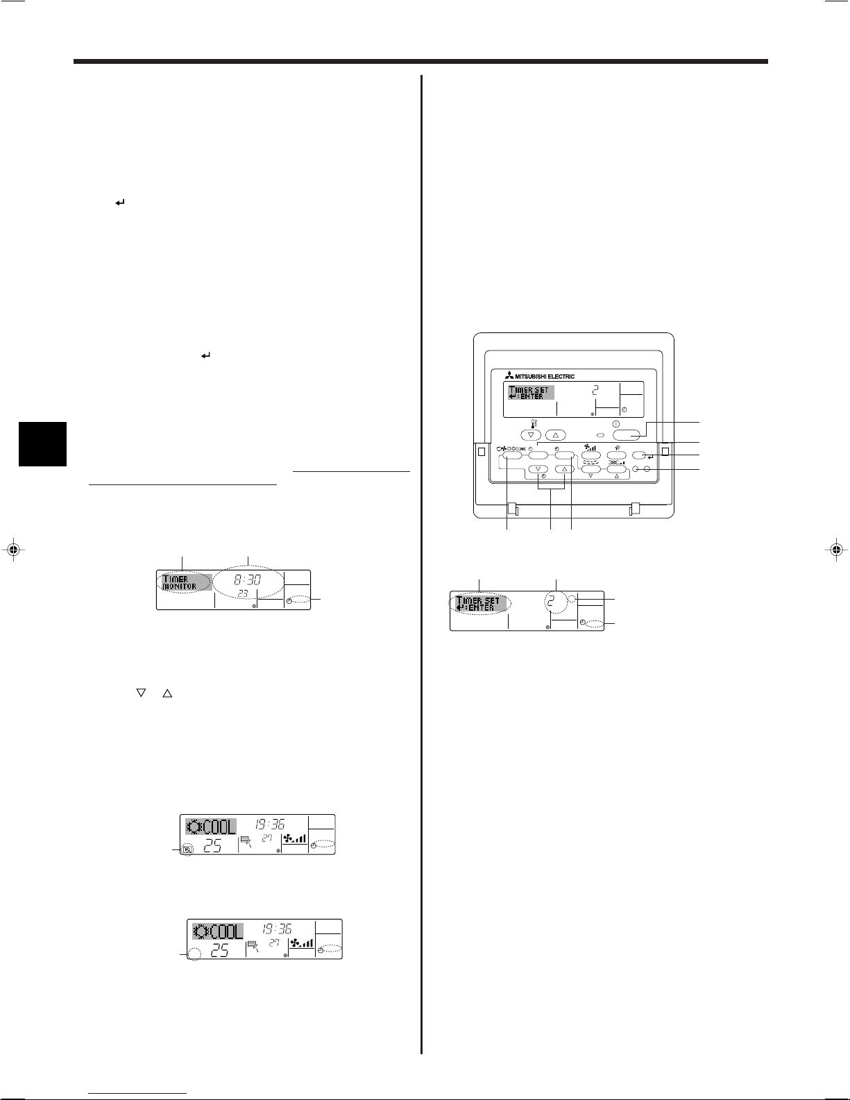
<How to View the Weekly Timer Settings>
Timer Settings
1.
Be sure that the weekly timer indicator is visible on the screen (at 1).
2. Press the Timer Menu button B so that “Monitor” is indicated on the
screen (at 8).
3. Press the Timer On/Off (Set Day) button 9 as necessary to select the
day you wish to view.
4. Press the or Operation button (7 or 8) as necessary to change
the timer operation shown on the display (at 9).
* Each press will advance to the next timer operation, in order of time
setting.
5. To close the monitor and return to the standard control screen, press
the Mode (Return) button 2.
<To Turn Off the Weekly Timer>
Press the Timer On/Off button 9 so that “Timer Off” appears at 0.
<To Turn On the Weekly Timer>
Press the Timer On/Off button 9 so that the “Timer Off” indication (at 0)
goes dark.
8
<How to Set the Simple Timer>
Timer Setting
Action (On or Off)
* “— —” is displayed if there is no
setting.
1. Be sure that you are at a standard control screen, and that the simple
timer indicator is visible in the display (at 1).
When something other than the Simple Timer is displayed, set it to
SIMPLE TIMER using the function selection of remote controller (see
8.[4]–3 (3)) timer function setting.
2. Press the Timer Menu button B, so that the “Set Up” appears on the
screen (at 2). (Note that each press of the button toggles the display
between “Set Up” and “Monitor”.)
3. Press the ON/OFF button 1 to display the current ON or OFF simple
timer setting. Press the button once to display the time remaining to ON,
and then again to display the time remaining to OFF. (The ON/OFF
indication appears at 3).
•“ON” timer:
The air conditioner will start operation when the specified number of
hours has elapsed.
•“OFF” timer:
The air conditioner will stop operation when the specified number of
hours has elapsed.
4. With “ON” or “OFF” showing at 3: Press the appropriate Set Time button
A as necessary to set the hours to ON (if “ON” is displayed) or the hours
to OFF (if “OFF” is displayed) at 4.
• Available Range: 1 to 72 hours
5. To set both the ON and OFF times, repeat Steps 3 and 4.
* Note that ON and OFF times cannot be set to the same value.
6. To clear the current ON or OFF setting: Display the ON or OFF setting
(see step 3) and then press the Check (Clear) button 0 so that the time
setting clears to “—” at 4. (If you want to use only an ON setting or only
an OFF setting, be sure that the setting you do not wish to use is shown
as “—”.)
TIMER ON
OFFHrAFTER
SIMPLE
1
6
5
˚C
˚C
SIMPLE
7
˚C
˚C
ONHr
AFTER
SIMPLE
7
ONHr
AFTER
SIMPLE
˚C
˚C
OFFHrAFTER
SIMPLE
SIMPLE
˚C
˚C
OFFHrAFTER
SIMPLE
ONHr
AFTER
SIMPLE
˚C
˚C
SIMPLE
AFTER OFF
AUTO OFF
PAR-21MAA
ON/OFF
FILTER
CHECK
OPERATION
CLEAR
TEST
TEMP.
MENU
BACK DAY
MONITOR/SET
CLOCK
ON/OFF
2A9
4
B
AFTER OFF
AUTO OFF
3
1
2
6. Timer
7. After completing steps 3 to 6 above, press the Filter button 4 to lock
in the value.
Note:
Your new settings will be cancelled if you press the Mode (Return) button 2
before pressing the Filter
button 4.
8. Press the Mode (Return) button 2 to return to the standard control
screen.
9. Press the Timer On/Off button 9 to start the timer countdown. When the
timer is running, the timer value is visible on the display. Be sure that the
timer value is visible and appropriate.
<Viewing the Current Simple Timer Settings>
Timer Setting
1. Be sure that the simple timer indicator is visible on the screen (at 1).
2. Press the Timer Menu button B, so that the “Monitor” appears on the
screen (at 5).
• If the ON or OFF simple timer is running, the current timer value will
appear at 6.
• If ON and OFF values have both been set, the two values appear
alternately.
3. Press the Mode (Return) button 2 to close the monitor display and return
to the standard control screen.
<To Turn Off the Simple Timer...>
Press the Timer On/Off button 9 so that the timer setting no longer appears on the screen (at 7).
Example 2:
Start the timer, with OFF time is sooner than ON time
ON Setting: 5 hours
OFF Setting: 2 hours
At Timer Start
Display shows the timer’s OFF setting (hours
▲
remaining to OFF).
At 2 hours after timer start
Display changes to show the timer’s ON setting
(hours remaining to ON).
▲
The time displayed is ON setting (5 hours) –
OFF setting (2 hours) = 3 hours.
At 5 hours after timer start
The air conditioner comes on, and will continue
to run until someone turns it off.
6.1.3. Auto Off Timer
■ This timer begins countdown when the air conditioner starts, and shuts
the air conditioner off when the set time has elapsed.
■ Available settings run from 30 minutes to 4 hours, in 30-minute intervals.
Note:
*1. Weekly Timer/Simple Timer/Auto Off Timer cannot be used at the same time.
*2. The Auto Off timer will not operate when any of the following conditions is
in effect.
The timer is off; the system is in malfunction state; a test run is in progress;
the remote controller is undergoing self-check or remote controller check;
the user is in the process of selecting a function; the user is in the process
of setting the timer; the system is under central control. (Under these conditions, On/Off operation is prohibited.)
<To Turn On the Simple Timer...>
Press the Timer On/Off button 9 so that the timer setting becomes visible
at 7.
Examples
If ON and OFF times have both been set at the simple timer, operation and
display are as indicated below.
Example 1:
Start the timer, with ON time set sooner than OFF time
ON Setting: 3 hours
OFF Setting: 7 hours
At Timer Start
Display shows the timer’s ON setting (hours
▲
▲
remaining to ON).
At 3 hours after timer start
Display changes to show the timer’s OFF setting (hours remaining to OFF).
The time displayed is OFF setting (7 hours) –
ON setting (3 hours) = 4 hours.
At 7 hours after timer start
The air conditioner goes off, and will remain off
until someone restarts it.
<How to Set the Auto Off Timer>
Timer Setting
1. Be sure that you are at a standard control screen, and that the Auto Off
timer indicator is visible in the display (at 1).
When something other than the Auto Off Timer is displayed, set it to
AUTO OFF TIMER using the function selection of remote controller (see
8.[4]–3 (3)) timer function setting.
2. Hold down the Timer Menu button B for 3 seconds, so that the “Set Up”
appears on the screen (at 2).
(Note that each press of the button toggles the display between “Set Up”
and “Monitor”.)
3. Press the appropriate Set Time button A as necessary to set the OFF
time (at 3).
4. Press the Filter button 4 to lock in the setting.
Note:
Your entry will be cancelled if you press the Mode (Return) button 2 before
pressing the Filter
button 4.
5. Press the Mode (Return) button 2 to complete the setting procedure and
return to the standard control screen.
6. If the air conditioner is already running, the timer starts countdown
immediately. Be sure to check that the timer setting appears cor-
rectly on the display.
9
AFTER
TIMER
OFF
AUTO OFF
5
1
4
˚C
˚C
AUTO OFF
6
7
AUTO OFF
7
˚C
˚C
AFTER OFF
AUTO OFF
6
7
˚C
˚C
TIME SUN
FUNCTION
PAR-21MAA
ON/OFF
FILTER
CHECK
OPERATION
CLEAR
TEST
TEMP.
MENU
BACK DAY
MONITOR/SET
CLOCK
ON/OFF
4
1
1
˚C
˚C
FUNCTION
1
˚C
˚C
FUNCTION
1
˚C
˚C
1
6. Timer
<Checking the Current Auto Off Timer Setting>
Timer Setting
1. Be sure that the “Auto Off” is visible on the screen (at 1).
2. Hold down the Timer Menu button B for 3 seconds, so that “Monitor” is
indicated on the screen (at 4).
• The timer remaining to shutdown appears at 5.
3. To close the monitor and return to the standard control screen, press the
Mode (Return) button 2.
<To Turn Off the Auto Off Timer...>
● Hold down the Timer On/Off button 9 for 3 seconds, so that “Timer Off”
appears (at 6) and the timer value (at 7) disappears.
7. Other Functions
7.1. Locking the Remote Controller Buttons (Operation
function limit controller)
■ If you wish, you can lock the remote controller buttons. You can use the
Function Selection of remote controller to select which type of lock to use.
(For information about selecting the lock type, see section 8, item [4]–2
(1)).
Specifically, you can use either of the following two lock types.
1 Lock All Buttons:
Locks all of the buttons on the remote controller.
2 Lock All Except ON/OFF:
Locks all buttons other than the ON/OFF button.
Note:
The “Locked” indicator appears on the screen to indicate that buttons are currently locked.
● Alternatively, turn off the air conditioner itself. The timer value (at 7) will
disappear from the screen.
<To Turn On the Auto Off Timer...>
● Hold down the Timer On/Off button 9 for 3 seconds. The “Timer Off”
indication disappears (at 6), and the timer setting comes on the display
(at 7).
● Alternatively, turn on the air conditioner. The timer value will appear at 7.
<How to Lock the Buttons>
1. While holding down the Filter button 4, press and hold down the ON/OFF
button 1 for 2 seconds. The “Locked” indication appears on the screen
(at 1), indicating that the lock is now engaged.
* If locking has been disabled in Function Selection of remote controller,
the screen will display the “Not Available” message when you press the
buttons as described above.
• If you press a locked button, the “Locked” indication (at 1) will blink on
the display.
10
Lock Indicator
<How to Unlock the Buttons>
1. While holding down the Filter button 4, press and hold down the ON/
OFF button 1 for 2 seconds—so that the “Locked” indication disappears
from the screen (at 1).
ON/OFF
˚C
˚C
ERROR CODE
ON/OFF
CALL:XXXX
XXX:XXX
7. Other Functions
ON/OFF
ERROR CODE
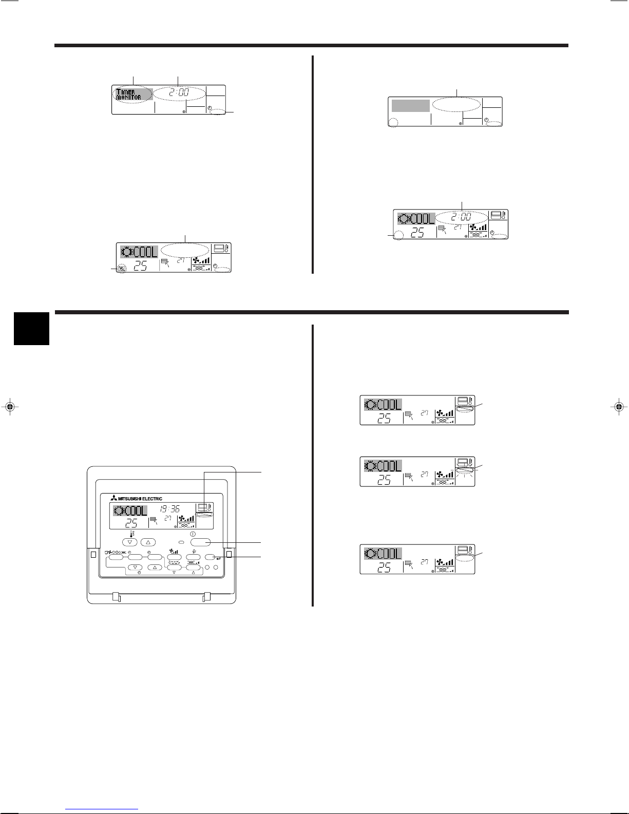
7.2. Error Codes indication
ON lamp
(Flashing)
Unit No.
If you have entered contact number to be called in the event of a problem, the screen displays this number.
(You can set this up under Function Selection of remote controller. For information, refer to section 8.)
Error Code
● If the ON lamp and error code are both flashing: This means that the air conditioner is out of order and operation has been stopped (and cannot resume).
Take note of the indicated unit number and error code, then switch off the power to the air conditioner and call your dealer or servicer.
When the Check button is pressed:
Error Code
● If only the error code is flashing (while the ON lamp remains lit): Operation is continuing, but there may be a problem with the system. In this case, you
should note down the error code and then call your dealer or servicer for advice.
* If you have entered contact number to be called in the event of a problem, push the Check button to display it on the screen. (You can set this up under
Function Selection of remote controller. For information, refer to section 8.)
8. Function Selection
Function selection of remote controller
The setting of the following remote controller functions can be changed using the remote controller function selection mode. Change the setting when
needed.
Item 1
1. Change Language
(“CHANGE
LANGUAGE”)
2. Function limit
(“FUNCTION
SELECTION”)
3. Mode selection
(“MODE SELECTION”)
4. Display change
(“DISP MODE
SETTING”)
Item 2
Language setting to display
(1) Operation function limit setting (operation lock) (“LOCKING
FUNCTION”)
(2) Use of automatic mode setting (“SELECT AUTO MODE”)
(3) Temperature range limit setting (“LIMIT TEMP FUNCTION”)
(1) Remote controller main/sub setting (“CONTROLLER MAIN/
SUB”)
(2) Use of clock setting (“CLOCK”)
(3) Timer function setting (“WEEKLY TIMER”)
(4) Contact number setting for error situation (“CALL.”)
(1) Temperature display °C/°F setting (“TEMP MODE °C/°F”)
(2) Suction air temperature display setting (“ROOM TEMP DISP
SELECT”)
(3) Automatic cooling/heating display setting (“AUTO MODE
DISP C/H”)
• Display in multiple languages is possible
• Setting the range of operation limit (operation lock)
• Setting the use or non-use of “automatic” operation mode
• Setting the temperature adjustable range (maximum, minimum)
• Selecting main or sub remote controller
* When two remote controllers are connected to one group, one controller
must be set to sub.
• Setting the use or non-use of clock function
• Setting the timer type
• Contact number display in case of error
• Setting the telephone number
• Setting the temperature unit (°C or °F) to display
• Setting the use or non-use of the display of indoor (suction) air tempera-
ture
• Setting the use or non-use of the display of “Cooling” or “Heating” display
during operation with automatic mode
Item 3 (Setting content)
11
OFF
on1
on2
OFF
ON
OFF
ON
OFF
OFF
CALL-
ON
OFF
ON
OFF
°C
°F
PAR-21MAA
ON/OFF
FILTER
CHECK
OPERATION
CLEAR
TEST
TEMP.
MENU
BACK DAY
MONITOR/SET
CLOCK
ON/OFF
F
E
G
C
D
H
B
A
I
G
G
G
G
G
G
E
E
G
G
G
G
G
E
G
E
G
G
G
G
D
D
D
D
D
D
D
D
D
D
D
D
D
D
D
D
D
D
D
D
D
D
D
D
D
D
D
D
D
D
English
Germany
Spanish
Russian
Italy
Chinese
French
Japanese
8. Function Selection
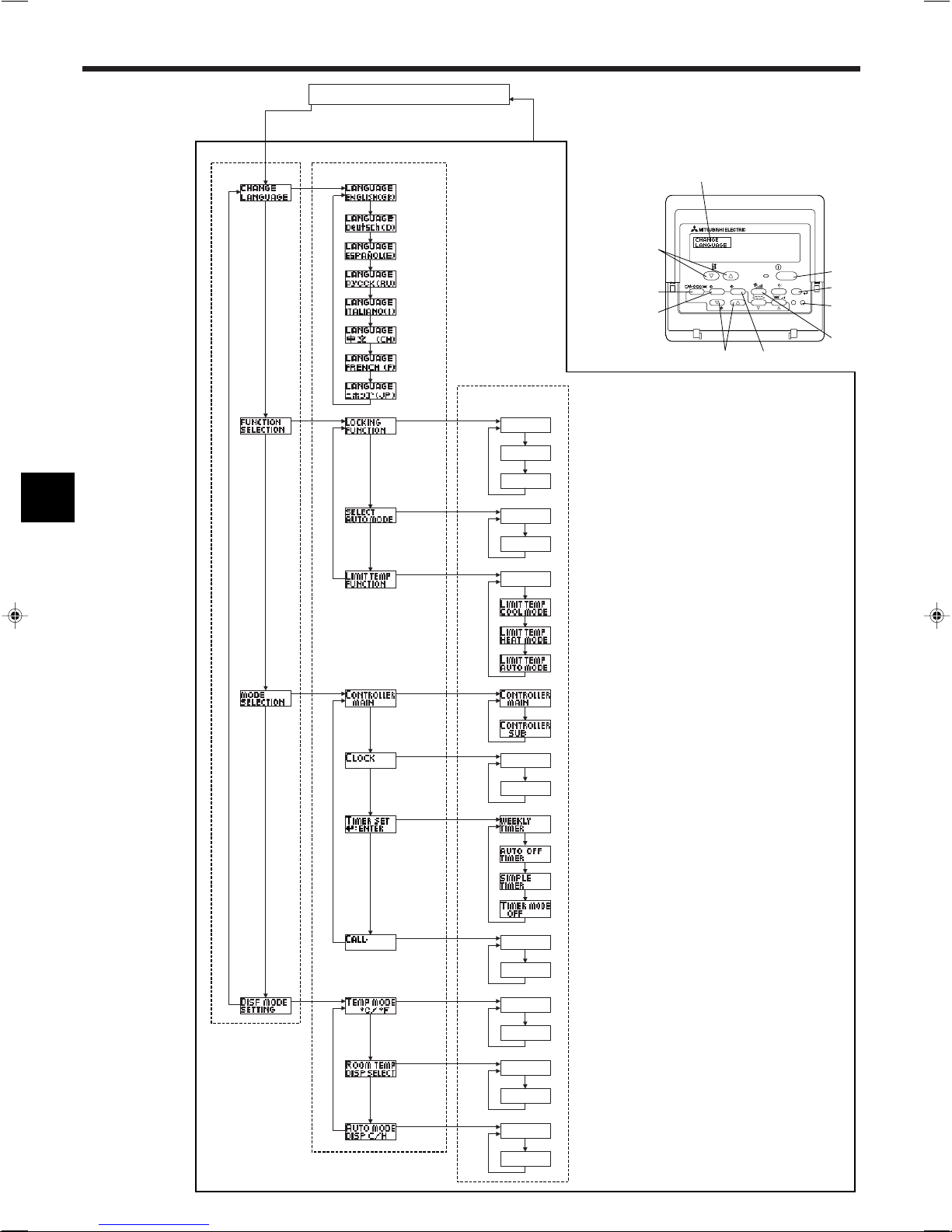
[Function selection flowchart]
Setting language (English)
Change
Language
Function
selection
Hold down the E button and press the D button for 2 seconds.
Remote controller function selection mode
Item1 Item2
Normal display
(Display when the air condition is not running)
Item3
Hold down the E button and press the D button for 2 seconds.
E Press the operation mode button.
G Press the TIMER MENU button.
D Press the TIMER ON/OFF button.
Dot display
Operation lock setting is not used.
(Initial setting value)
Operation lock setting is except On/Off button.
Operation lock setting is All buttons.
The automatic mode is displayed when the operation mode is
selected. (Initial setting value)
The automatic mode is not displayed when the operation mode
is selected.
The temperature range limit is not active. (Initial setting value)
The temperature range can be changed on cooling/dry mode.
The temperature range can be changed on heating mode.
Mode
selection
The temperature range can be changed on automatic mode.
The remote controller will be the main controller. (Initial setting value)
The remote controller will be the sub controller.
The clock function can be used. (Initial setting value)
The clock function can not be used.
Weekly timer can be used. (Initial setting value)
Auto off timer can be used.
Display
mode setting
Simple timer can be used.
Timer mode can not be used.
The set contact numbers are not displayed in case of error.
(Initial setting value)
The set contact numbers are displayed in case of error.
The temperature unit °C is used. (Initial setting value)
The temperature unit °F is used.
Room air temperature is displayed. (Initial setting value)
Room air temperature is not displayed.
One of “Automatic cooling” and “Automatic heating” is displayed
under the automatic mode is running. (Initial setting value)
Only “Automatic” is displayed under the automatic mode.
12
8. Function Selection
[Detailed setting]
[4]–1. CHANGE LANGUAGE setting
The language that appears on the dot display can be selected.
• Press the [ MENU] button G to change the language.
1 English (GB), 2 German (D), 3 Spanish (E), 4 Russian (RU),
5 Italian (I), 6 Chinese (CH), 7 French (F), 8 Japanese (JP)
Refer to the dot display table.
[4]–2. Function limit
(1) Operation function limit setting (operation lock)
• To switch the setting, press the [ ON/OFF] button D.
1 no1: Operation lock setting is made on all buttons other than the
[ ON/OFF] button.
2 no2: Operation lock setting is made on all buttons.
3 OFF (Initial setting value): Operation lock setting is not made.
* To make the operation lock setting valid on the normal screen, it is
necessary to press buttons (Press and hold down the [FILTER] and
[ ON/OFF] buttons at the same time for two seconds.) on the
normal screen after the above setting is made.
(2) Use of automatic mode setting
When the remote controller is connected to the unit that has automatic
operation mode, the following settings can be made.
• To switch the setting, press the [ ON/OFF] button D.
1 ON (Initial setting value):
The automatic mode is displayed when the operation mode is
selected.
2 OFF:
The automatic mode is not displayed when the operation mode
is selected.
(3) Temperature range limit setting
After this setting is made, the temperature can be changed within the
set range.
• To switch the setting, press the [ ON/OFF] button D.
1 LIMIT TEMP COOL MODE:
The temperature range can be changed on cooling/dry mode.
2 LIMIT TEMP HEAT MODE:
The temperature range can be changed on heating mode.
3 LIMIT TEMP AUTO MODE:
The temperature range can be changed on automatic mode.
4 OFF (initial setting): The temperature range limit is not active.
* When the setting, other than OFF, is made, the temperature range
limit setting on cooling, heating and automatic mode is made at the
same time. However, the range cannot be limited when the set
temperature range has not changed.
• To increase or decrease the temperature, press the [ TEMP. ( )
or ( )] button F.
• To switch the upper limit setting and the lower limit setting, press the
[ ] button H. The selected setting will flash and the temperature
can be set.
• Settable range
Cooling/Dry mode:
Lower limit:19°C ~ 30°C Upper limit:30°C ~ 19°C
Heating mode:
Lower limit:17°C ~ 28°C Upper limit:28°C ~ 17°C
Automatic mode:
Lower limit:19°C ~ 28°C Upper limit:28°C ~ 19°C
[4]–3. Mode selection setting
(1) Remote controller main/sub setting
• To switch the setting, press the [ ON/OFF] button D.
1 Main: The controller will be the main controller.
2 Sub: The controller will be the sub controller.
(2) Use of clock setting
• To switch the setting, press the [ ON/OFF] button D.
1 ON: The clock function can be used.
2 OFF: The clock function cannot be used.
(3) Timer function setting
• To switch the setting, press the [ ON/OFF] button D (Choose one
of the following.).
1 WEEKLY TIMER (initial setting value):
The weekly timer can be used.
2 AUTO OFF TIMER:
The auto off timer can be used.
3 SIMPLE TIMER:
The simple timer can be used.
4 TIMER MODE OFF:
The timer mode cannot be used.
* When the use of clock setting is OFF, the “WEEKLY TIMER” cannot
be used.
(4) Contact number setting for error situation
• To switch the setting, press the [ ON/OFF] button D.
1 CALL OFF:
The set contact numbers are not displayed in case of error.
2 CALL **** *** ****:
The set contact numbers are displayed in case of error.
CALL_:
The contact number can be set when the display is as shown on
the left.
• Setting the contact numbers
To set the contact numbers, follow the following procedures.
Move the flashing cursor to set numbers. Press the [ TEMP.
( ) and ( )] button F to move the cursor to the right (left). Press
the [ CLOCK ( ) and ( )] button C to set the numbers.
[4]–4. Display change setting
(1) Temperature display °C/°F setting
• To switch the setting, press the [ ON/OFF] button D.
1 °C: The temperature unit °C is used.
2 °F: The temperature unit °F is used.
(2) Suction air temperature display setting
• To switch the setting, press the [ ON/OFF] button D.
1 ON: The suction air temperature is displayed.
2 OFF: The suction air temperature is not displayed.
(3) Automatic cooling/heating display setting
• To switch the setting, press the [ ON/OFF] button D.
1 ON:
One of “Automatic cooling” and “Automatic heating” is displayed
under the automatic mode is running.
2 OFF:
Only “Automatic” is displayed under the automatic mode.
13

8. Function Selection
[Dot display table]
Selecting language
Waiting for start-up
Operation mode Cool
Dry
Heat
Auto
Auto(Cool)
Auto(Heat)
Fan
Ventilation
Stand by
(Hot adjust)
Defrost
Set temperature
Fan speed
Not use button
Check (Error)
Test run
Self check
Unit function selection
Setting of ventilation
English Germany Spanish Russian Italy Chinese French Japanese
Selecting language
CHANGE LANGUAGE
Function selection
Operation function limit setting
Use of automatic mode setting
Temperature range limit setting
Limit temperature cooling/day
mode
Limit temperature heating mode
Limit temperature auto mode
Mode selection
Remote controller setting MAIN
Remote controller setting SUB
Use of clock setting
Setting the day of the week and
time
Timer set
Timer monitor
Weekly timer
Timer mode off
Auto off timer
Simple timer
Contact number setting of error
situation
Display change
Temperature display °C/°F setting
Room air temperature display
setting
Automatic cooling/heating display
setting
English Germany Spanish Russian Italy Chinese French Japanese
14
ON/OFF
TEMP.
˚C
˚C
FILTER
9. Care and Cleaning
B
A
D
C
C
B
D
A
B
A
■ Indicates that the filter needs cleaning.
Clean the filter.
■ When resetting “FILTER” display
When the [FILTER] button is pressed two times successively after
cleaning the filter, the display goes off and is reset.
■ PKFY-P·VAM-E
PKFY-P·VGM-E
Note:
● When two or more different types of indoor unit are controlled, the cleaning
period differs with the type of filter. When the master unit cleaning period
arrives, “FILTER” is displayed. When the filter display goes off, the cumulative time is reset.
● “FILTER” indicates the cleaning period when the air conditioner was used
under general indoor air conditions by criteria time. Since the degree of dirtiness depends on the environmental conditions, clean the filter accordingly.
● The filter cleaning period cumulative time differs with the model.
● This indication is not available for wireless remote controller.
ss
sCleaning the filters
ss
• Clean the filters using a vacuum cleaner. If you do not have a vacuum
cleaner, tap the filters against a solid object to knock off dirt and dust.
• If the filters are especially dirty, wash them in lukewarm water. Take care
to rinse off any detergent thoroughly and allow the filters to dry completely before putting them back into the unit.
Caution:
• Do not dry the filters in direct sunlight or by using a heat source,
such as an electric heater: this may warp them.
• Do not wash the filters in hot water (above 50°C), as this may warp
them.
• Make sure that the air filters are always installed. Operating the
unit without air filters can cause malfunction.
Caution:
• Before you start cleaning, stop operation and turn OFF the power
supply.
• Indoor units are equipped with filters to remove the dust of sucked-in
air. Clean the filters using the methods shown in the following sketches.
ss
sFilter removal
ss
Caution:
• In removing the filter, precautions must be taken to protect your
eyes from dust. Also, if you have to climb up on a stool to do the
job, be careful not to fall.
• When the filter is removed, do not touch the metallic parts inside
the indoor unit, otherwise injury may result.
■ PLFY-P·VAM-E
1 Pull both the bottom corners of the intake grille to open the grille,
then lift the filter.
■ PKFY-P·VFM-E
1 Hold the filter lug (located at the bottom of the intake grille) and pull it
out downward.
AFilter
BLug
• To reinstall the filters, push the filter lug upward.
■ PCFY-P·VGM-E
1 Open the intake grille.
2 Hold the knob on the filter then pull the filter up in the direction of an
arrow. To replace the filter after cleaning, be sure to insert the filter
far enough until it fits into the stopper.
AFilter BIntake Grille CKnob DStopper
■ PMFY-P·VBM-E
1 Pull the knob on the intake grille in the direction indicated by the
arrow and it should open.
2 Open the intake grille.
3 Release the knob on the center edge of the intake grille and pull the
filter forward to remove the filter.
A Knob B Grille C Intake grille D Filter
1 Pressing the PUSH button on the outer side of the intake grille causes
the intake grille to open.
2 A filter with an intake grille on it can be removed by pulling the filter
forward.
15
B
A
C
9. Care and Cleaning
■ PFFY-P·VKM-E
10. Trouble Shooting
Having trouble?
Air conditioner does not heat or cool well.
When heating operation starts, warm air does not blow from the indoor unit
soon.
During heating mode, the air conditioner stops before the set room temperature is reached.
Airflow direction changes during operation or airflow direction cannot be
set.
When the airflow direction is changed, the vanes always move up and down
past the set position before finally stopping at the position.
A flowing water sound or occasional hissing sound is heard.
A cracking or creaking sound is heard.
The room has an unpleasant odor.
A white mist or vapor is emitted from the indoor unit.
Water or vapor is emitted from the outdoor unit.
The operation indicator does not appear in the remote controller display.
The air conditioner does not operate even though the ON/OFF button is
pressed. The operation mode display on the remote controller disappears.
“ ” appears in the remote controller display.
■ PFFY-P·VKM-E
1 Remove the catechin air filter.
AOpen the front grille
BCatechin air filter
Caution:
When the catechin air filter is to be removed, do not touch the metal
parts of the indoor unit.
This may cause an injury.
2 Install the catechin air filter.
Be sure to install its both ends into the tabs as shown.
CInstall.
3 Securely close the front grille.
Here is the solution. (Unit is operating normally.)
■ Clean the filter. (Airflow is reduced when the filter is dirty or clogged.)
■ Check the temperature adjustment and adjust the set temperature.
■ Make sure that there is plenty of space around the outdoor unit. Is the
indoor unit air intake or outlet blocked?
■ Has a door or window been left open?
■ Warm air does not blow until the indoor unit has sufficiently warmed up.
■ When the outdoor temperature is low and the humidity is high, frost may
form on the outdoor unit. If this occurs, the outdoor unit performs a defrosting operation. Normal operation should begin after approximately 10
minutes.
■ During cooling mode, the vanes automatically move to the horizontal
(down) position after 1 hour when the down (horizontal) airflow direction
is selected. This is to prevent water from forming and dripping from the
vanes.
■ During heating mode, the vanes automatically move to the horizontal
airflow direction when the airflow temperature is low or during defrosting
mode.
■ When the airflow direction is changed, the vanes move to the set position
after detecting the base position.
■ These sounds can be heard when refrigerant is flowing in the air conditioner or when the refrigerant flow is changing.
■ These sounds can be heard when parts rub against each due to expansion and contraction from temperature changes.
■ The indoor unit draws in air that contains gases produced from the walls,
carpeting, and furniture as well as odors trapped in clothing, and then
blows this air back into the room.
■ If the indoor temperature and the humidity are high, this condition may
occur when operation starts.
■ During defrosting mode, cool airflow may blow down and appear like a
mist.
■ During cooling mode, water may form and drip from the cool pipes and
joints.
■ During heating mode, water may form and drip from the heat exchanger.
■ During defrosting mode, water on the heat exchanger evaporates and
water vapor may be emitted.
■ Turn on the power switch. “ ” will appear in the remote controller display.
■ Is the power switch of the indoor unit turned off? Turn on the power switch.
■ During central control, “ ” appears in the remote controller display and
air conditioner operation cannot be started or stopped using the remote
controller.
16
WEEKLY
SIMPLE
AUTO OFF
10. Trouble Shooting
Having trouble?
When restarting the air conditioner soon after stopping it, it does not operate even though the ON/OFF button is pressed.
Air conditioner operates without the ON/OFF button being pressed.
Air conditioner stops without the ON/OFF button being pressed.
Remote controller timer operation cannot be set.
“PLEASE WAIT” appears in the remote controller display.
An error code appears in the remote controller display.
Draining water or motor rotation sound is heard.
Noise is louder than specifications.
Nothing appears in the wireless remote controller display, the display is
faint, or signals are not received by the indoor unit unless the remote controller is close.
The operation lamp near the receiver for the wireless remote controller on
the indoor unit is flashing.
Warm air blows from the indoor unit intermittently when heating mode is off
or during fan mode.
The damper opens and closes automatically.
(For PFFY-P·VKM-E series)
Here is the solution. (Unit is operating normally.)
■ Wait approximately three minutes.
(Operation has stopped to protect the air conditioner.)
■ Is the on timer set?
Press the ON/OFF button to stop operation.
■ Is the air conditioner connected to a central remote controller?
Consult the concerned people who control the air conditioner.
■ Does “ ” appear in the remote controller display?
Consult the concerned people who control the air conditioner.
■ Has the auto recovery feature from power failures been set?
Press the ON/OFF button to stop operation.
■ Is the off timer set?
Press the ON/OFF button to restart operation.
■ Is the air conditioner connected to a central remote controller?
Consult the concerned people who control the air conditioner.
■ Does “ ” appear in the remote controller display?
Consult the concerned people who control the air conditioner.
■ Are timer settings invalid?
If the timer can be set,
the remote controller display.
■ The initial settings are being performed. Wait approximately 3 minutes.
■ The protection devices have operated to protect the air conditioner.
■ Do not attempt to repair this equipment by yourself.
Turn off the power switch immediately and consult your dealer. Be sure
to provide the dealer with the model name and information that appeared
in the remote controller display.
■ When cooling operation stops, the drain pump operates and then stops.
Wait approximately 3 minutes.
■ The indoor operation sound level is affected by the acoustics of the particular room as shown in the following table and will be higher than the
noise specification, which was measured in an echo-free room.
High soundabsorbing rooms
Location
examples
Noise levels
■ The batteries are low.
Replace the batteries and press the Reset button.
■ If nothing appears even after the batteries are replaced, make sure that
the batteries are installed in the correct directions (+, –).
■ The self diagnosis function has operated to protect the air conditioner.
■ Do not attempt to repair this equipment by yourself.
Turn off the power switch immediately and consult your dealer. Be sure
to provide the dealer with the model name.
■ When another indoor unit is operating in heating mode, the control valve
opens and closes occasionally to maintain stability in the air conditioning
system. This operation will stop after a while.
* If this will cause an undesirable rise in the room temperature in small
rooms, etc., stop the operation of the indoor unit temporarily.
■ The damper is automatically controlled by a microcomputer according to
the air flow temperature and operation time of the air conditioner.
Broadcasting
studio, music
room, etc.
3 to 7 dB
,
Normal rooms
Reception room,
hotel lobby, etc.
6 to 10 dB
, or
appears in
Low soundabsorbing rooms
Office, hotel
room
9 to 13 dB
17
10. Trouble Shooting
ss
sAir outlet control (PFFY-P·VKM series)
ss
This unit is automatically controlled that air comes out simultaneously from the upper and lower air outlets so that the room can be cooled or heated
effectively.
Description of operation
Operation
Air flow
COOL
DRY
HEAT FAN
Upper and lower air flow
Room temperature
Conditions
• Be sure to keep the area around the damper of the lower air outlet free of any objects.
This unit can be set to blow out air from the upper air outlet only by changing the switch setting on the address board (ask the dealer).
Range of application
The range of working temperatures for both the indoor and outdoor units of the series Y, R2, Multi-S is as below.
Caution:
The use of your air conditioner outside the range of working temperature and humidity can result in serious failure.
Mode
Cooling
Heating
Note:As an applicable humidity standard for both indoors and outdoors, we recommend use within a range of 30 - 80% relative humidity.
Warning:
If the air conditioner operates but does not cool or heat (depending on model) the room, consult your dealer since there may be a refrigerant
leak. Be sure to ask the service representative whether there is refrigerant leakage or not when repairs are carried out.
The refrigerant charged in the air conditioner is safe. Refrigerant normally does not leak, however, if refrigerant gas leaks indoors, and comes
into contact with the fire of a fan heater, space heater, stove, etc., harmful substances will be generated.
and set temperature
are different.
Indoor unit
15 °C - 24 °C WB
15 °C - 27 °C DB
Upper air flow
Room temperature is
close to set temperature or thermo-off.
PUHY
–5 °C - 43 °C DB
–15 °C - 15.5 °C WB
Upper air flow only—Upper and lower air flow
(Normal condition (in
heating))
Outdoor unit
PURY
–5 °C - 43 °C DB
–12 °C - 15 °C WB
–12 °C - 15.5 °C WB
Upper air flow
During defrosting operation, start of operation, thermo-off
PUMY
–5 °C - 46 °C DB
Upper and lower air flow
—
18
11. Specifications
■ PLFY-P·VAM-E Series
Model P32 P40 P50 P63 P80 P100 P125
Power source (Voltage<V>/Frequency) <Hz> ~N/220-230-240/50, 220/60
Capacity (Cooling/Heating) <kW> 3.6/4.0 4.5/5.0 5.6/6.3 7.1/8.0 9.0/10.0 11.2/12.5 14.0/16.0
Dimension (Height) <mm> 258 (30) 298 (30)
Dimension (Width) <mm> 840 (950)
Dimension (Depth) <mm> 840 (950)
Net weight <kg> 22 (5) 24 (5) 32(5)
Fan Airflow rate
Noise level
*1 Cooling/Heating capacity indicates the maximum value at operation under the following condition.
Cooling: Indoor 27 °C DB/19 °C WB, Outdoor 35 °C DB
Heating: Indoor 20 °C DB, Outdoor 7 °C DB/6 °C WB
*2 This figure ( ) indicates panel’s.
■ PCFY-P·VGM-E Series
Model P40 P63 P100 P125
Power source (Voltage<V>/Frequency) <Hz> ~N/220-230-240/50, 220/60
Capacity (Cooling/Heating) <kW> 4.5/5.0 7.1/8.0 11.2/12.5 14.0/16.0
Dimension (Height) <mm> 210 270
Dimension (Width) <mm> 1000 1310 1620
Dimension (Depth) <mm> 680
Net weight <kg> 27 34 37 43
Fan Airflow rate
Noise level
*1 Cooling/Heating capacity indicates the maximum value at operation under the following condition.
Cooling: Indoor 27 °C DB/19 °C WB, Outdoor 35 °C DB
Heating: Indoor 20 °C DB, Outdoor 7 °C DB/6 °C WB
■ PKFY-P·VAM-E Series
Model P20 P25 P32 P40 P50 P63 P100
Power source (Voltage<V>/Frequency) <Hz> ~N/220-230-240/50, 220/60
Capacity (Cooling/Heating) <kW> 2.2/2.5 2.8/3.2 3.6/4.0 4.5/5.0 5.6/6.3 7.1/8.0 11.2/12.5
Dimension (Height) <mm> 295 340 340
Dimension (Width) <mm> 815 990 1400 1680
Dimension (Depth) <mm> 158 235 235
Net weight <kg> 8.5 16 24 28
Fan Airflow rate
Noise level
*1 Cooling/Heating capacity indicates the maximum value at operation under the following condition.
Cooling: Indoor 27 °C DB/19 °C WB, Outdoor 35 °C DB
Heating: Indoor 20 °C DB, Outdoor 7 °C DB/6 °C WB
(Low-Middle2-Middle1-High)
(Low-Middle2-Middle1-High)
(Low-Middle2-Middle1-High)
(Low-Middle2-Middle1-High)
(Low-Middle2-Middle1-High)
(Low-Middle2-Middle1-High)
<m3/min> 11-12-13-14 12-13-14-16 14-15-16-18 16-18-20-22 19-22-25-27 21-24-27-29
<dB> 27-28-29-31 27-28-30-32 28-29-31-33 30-32-35-37 33-36-39-41 35-38-41-43
<m3/min> 8-10-11-12 12-14-16-18 18-20-23-25 26-28-32-35
<dB> 29-33-36-38 32-34-37-39 36-38-41-43 37-39-42-44
■ PKFY-P·VGM-E Series ■ PKFY-P·VFM-E Series
<m3/min> 4.9-5.2-5.6-5.9 8-9.5-10.5-11.5 9-10-11-12 15-20 22-28
<dB> 32-33-35-36 33-36-38-41 34-37-40-43 39-45 41-46
■ PMFY-P·VBM-E Series
Model P20 P25 P32 P40
Power source (Voltage<V>/Frequency) <Hz> ~N/220-230-240/50, 220/60
Capacity (Cooling/Heating) <kW> 2.2/2.5 2.8/3.2 3.6/4.0 4.5/5.0
Dimension (Height) <mm> 230 (30)
Dimension (Width) <mm> 854 (1000)
Dimension (Depth) <mm> 395 (470)
Net weight <kg> 14 (3.0)
Fan Airflow rate
Noise level
*1 Cooling/Heating capacity indicates the maximum value at operation under the following condition.
Cooling: Indoor 27 °C DB/19 °C WB, Outdoor 35 °C DB
Heating: Indoor 20 °C DB, Outdoor 7 °C DB/6 °C WB
*2 This figure ( ) indicates panel’s.
(Low-Middle2-Middle1-High)
(Low-Middle2-Middle1-High)
<m3/min>
6.5-7.2-8.0-8.6
<dB> 27-30-33-36 32-34-36-37 33-35-37-39
7.3-8.0-8.6-9.3
7.7-8.7-9.7-10.7
■ PFFY-P·VKM-E Series
Model P20 P25 P32 P40
Power source (Voltage<V>/Frequency) <Hz> ~N/220-230-240/50
Capacity (Cooling/Heating) <kW> 2.2/2.5 2.8/3.2 3.6/4.0 4.5/5.0
Dimension (Height) <mm> 600
Dimension (Width) <mm> 700
Dimension (Depth) <mm> 200
Net weight <kg> 14
Fan Airflow rate
Noise level
*1 Cooling/Heating capacity indicates the maximum value at operation under the following condition.
Cooling: Indoor 27 °C DB/19 °C WB, Outdoor 35 °C DB
Heating: Indoor 20 °C DB, Outdoor 7 °C DB/6 °C WB
(Low-Middle2-Middle1-High)
(Low-Middle2-Middle1-High)
<m3/min>
5.9-6.8-7.6-8.7
<dB> 27-31-34-37 28-32-35-38 35-38-42-44
6.1-7.0-8.0-9.1
8.0-9.0-9.5-10.7
19
Inhaltsverzeichnis
1. Sicherheitsvorkehrungen .................................................. 20
2. Bezeichnungen der Teile ................................................... 21
3. Bildschirmkonfiguration ..................................................... 23
4. Einstellen des Wochentags und der Zeit .......................... 23
5. Bedienung ......................................................................... 23
6. Timer ................................................................................. 25
1. Sicherheitsvorkehrungen
s Vor dem Einbau der Anlage vergewissern, dass Sie alle Infor-
mationen über “Sicherheitsvorkehrungen” gelesen haben.
s Die “Sicherheitsvorkehrungen” enthalten sehr wichtige
Sicherheitsgesichtspunkte. Sie sollten sie unbedingt befolgen.
s Vor Anschluss an das System Mitteilung an Stromversorgungs-
unternehmen machen oder dessen Genehmigung einholen.
Warnung:
• Die Anlage sollte nicht vom Benutzer eingebaut werden. Bitten Sie Ihren
Händler oder eine Vertragswerkstatt, die Anlage einzubauen. Wenn die Anlage unsachgemäß eingebaut wurde, kann Wasser auslaufen, können Stromschläge erfolgen, oder es kann Feuer ausbrechen.
• Nicht auf die Anlage stehen oder Gegenstände darauf ablegen.
• Kein Wasser über die Anlage spritzen und die Anlage auch nicht mit nassen
Händen berühren. Dies kann zu Stromschlägen führen.
• Kein brennbares Gas in der Nähe der Anlage versprühen. Es kann Feuer
ausbrechen.
• Keine Gasheizung oder sonstige Geräte mit offenen Flammen in Bereichen
abstellen, an denen Luft aus der Anlage ausströmt. Unvollständige Verbrennung kann die Folge sein.
• Wenn die Anlage läuft, nicht die Frontplatte oder den Gebläseschutz von der
Außenanlage abnehmen.
• Sie sollten die Anlage niemals eigenhändig reparieren oder an einen ande-
ren Standort verbringen.
Vorsicht:
• Zum Drücken der Tasten keine scharfen Gegenstände benutzen, da dadurch
die Fernbedienung beschädigt werden kann.
• Die Ansaug- oder Austrittsöffnungen weder der Innen- noch der Außenanla-
ge blockieren oder abdecken.
• Die Fernbedienung niemals mit Benzol, Verdünner, mit Chemikalien getränk-
ten Putzlappen usw. abwischen.
• Betreiben Sie die Klimaanlage niemals für längere Zeit bei hoher Luftfeuch-
tigkeit, z. B. bei geöffneter Tür oder geöffnetem Fenster. Falls die Klimaanlage für längere Zeit im Kühlbetrieb in einem Raum mit hoher Luftfeuchtigkeit
(80% oder mehr) betrieben wird, kann in der Klimaanlage kondensiertes
Wasser abtropfen und Möbel usw. nass werden lassen oder beschädigen.
7. Weitere Funktionen ........................................................... 28
8. Funktionsauswahl ............................................................. 29
9. Pflege und Reinigung ....................................................... 33
10. Fehlerbehebung ................................................................ 34
11. Technische daten.............................................................. 37
Im Text verwendete Symbole
Warnung:
Beschreibt Vorkehrungen, die beachtet werden sollten, um den Benutzer vor
der Gefahr von Verletzungen oder tödlicher Unfälle zu bewahren.
Vorsicht:
Beschreibt Vorkehrungen, die beachtet werden sollten, damit an der Anlage
keine Schäden entstehen.
In den Abbildungen verwendete Symbole
: Verweist auf einen Teil der Anlage, der geerdet werden muss.
• Wenn das Geräusch oder die Vibrationen anders als normal oder besonders
stark sind, den Betrieb einstellen, den Hauptschalter ausschalten, und das
Verkaufsgeschäft um Hilfe bitten.
• Niemals die Finger, Stöcke etc. in die Ansaug- oder Austrittsöffnungen stecken.
• Wenn Sie merkwürdige Gerüche feststellen, sollten Sie die Anlage nicht mehr
benutzen, den Strom abschalten und sich an Ihren Kundendienst wenden,
da sonst schwere Defekte an der Anlage, ein Stromschlag oder ein Brand
verursacht werden können.
• Diese Klimaanlage darf NICHT von Kindern oder unsicheren Personen ohne
Aufsicht benutzt werden.
• Kleine Kinder müssen beaufsichtigt werden, um sicherzustellen, dass sie
nicht an der Klimaanlage herumspielen.
• Wenn gasförmiges oder flüssiges Kühlmittel entweicht, die Klimaanlage
abstellen, den Raum ausreichend lüften und das Verkaufsgeschäft benachrichtigen.
• Berühren Sie während des Betriebs nicht den Flügel des oberen
Luftauslasses oder den Dämpfer des unteren Luftauslasses. Dadurch kann
Kondensation auftreten, wodurch der Betrieb stoppt.
Die Anlage entsorgen
Zum Entsorgen des Gerätes wenden Sie sich an Ihren Kundendienst.
20
2. Bezeichnungen der Teile
■ Inneneinheit
PLFY-P·VAM-E PKFY-P·VAM-E PKFY-P·VGM-E PKFY-P·VFM-E PCFY-P·VGM-E
Lüfterstufen 4 Stufen 4 Stufen 4 Stufen 2 Stufen 4 Stufen
Klappe Auto mit Schwingen Auto mit Schwingen Auto mit Schwingen Auto mit Schwingen Auto mit Schwingen
Luftklappe – Manuell Manuell Manuell Manuell
Filter Langlebig Normal Normal Normal Langlebig
Reinigungsempfehlung für Filter 2.500 Std. 100 Std. 100 Std. 100 Std. 2.500 Std.
PMFY-P·VBM-E PFFY-P·VKM-E
Lüfterstufen 4 Stufen 4 Stufen
Klappe Auto mit Schwingen Auto mit Schwingen
Luftklappe Manuell Manuell
Filter Normal Normal
Reinigungsempfehlung für Filter 100 Std. 100 Std.
■ PLFY-P·VAM-E
4-Wege-Deckenkassette
Filter
Lufteinlass
■ PKFY-P·VAM-E/PKFY-P·VGM-E
Wandgerä
Filter
Luftklappe
Lufteinlass
Luftauslass
Klappe
Klappe
Luftauslass
■ PMFY-P·VBM-E
1-Wege-Deckenkassette
Luftauslass
Filter
■ PKFY-P·VFM-E
Wandgerät
Luftklappe
Klappe
Lufteinlass
Filter
Luftauslass
Luftklappe
Lufteinlass
Klappe
■ PCFY-P·VGM-E
Unterdeckengerät
Luftklappe
Luftauslass
Klappe
Lufteinlass
Filter
■ PFFY-P·VKM-E
Bodenstehend
Luftauslass
Klappe
Filter
Luftstrom-Regeleinheit
Luftklappe
Lufteinlass
Luftauslass
Luftklappe
21
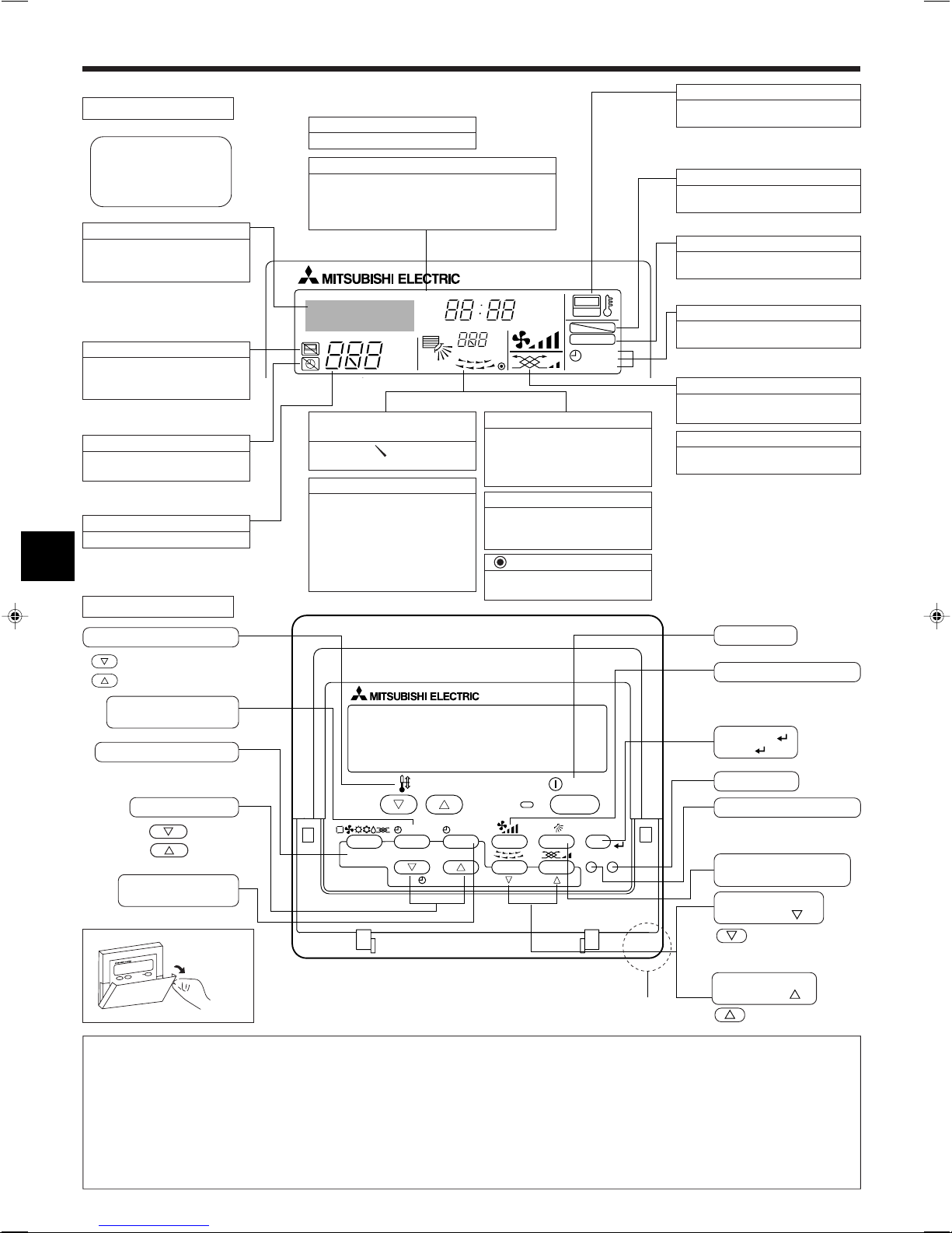
PAR-21MAA
ON/OFF
FILTER
CHECK
OPERATION
CLEAR
TEST
TEMP.
MENU
BACK DAY
MONITOR/SET
CLOCK
ON/OFF
2. Bezeichnungen der Teile
■ Für verdrahteter Fernbedienung
Display-Bereich
Für diese Erklärung werden alle
Teile des Displays als beleuchtet
dargestellt. Während dem tatsächlichen Betrieb sind nur die relevanten Elemente beleuchtet.
Zeigt den aktuellen Betrieb
Zeigt den Betriebsmodus, usw.
* Anzeige in mehreren Sprachen
wird unterstützt.
Anzeige Zentralsteuerung
Gibt an, dass der Betrieb der Fernbedienung durch eine MasterSteuerung deaktiviert wurde.
Anzeige “Timer Off”
Gibt an, dass der Timer ausgeschaltet ist.
Temperatureinstellung
Zeigt die Zieltemperatur an.
Kontrollbereich
Wochentag
Zeigt den aktuellen Wochentag an.
Zeit-/Timer-Anzeige
Zeigt die aktuelle Zeit an, außer der einfache oder der
Auto-Off-Timer ist eingestellt.
Falls der einfache oder der Auto-Off-Timer eingestellt ist, wird die Restzeit angezeigt.
TIME SUN MON TUE WED THU FRI SAT
TIMER
AFTER
ERROR CODE
˚F˚C
Hr
AFTER
˚F˚C
ONLY1Hr.
Anzeige der Luftrichtung nach
oben/nach unten
Die Anzeige gibt die Richtung
der herausströmenden Luft an.
Anzeige “One Hour Only”
Wird angezeigt, wenn der Luftstrom
im Modus COOL oder DRY auf
schwach und abwärts eingestellt ist.
(Der Betrieb unterscheidet sich je
nach Modell.)
Die Anzeige schaltet sich nach einer
Stunde aus, wenn sich die Richtung
des Luftstroms ebenfalls ändert.
Anzeige der Umgebungstemperatur
Zeigt die Umgebungstemperatur an.
Der Anzeigebereich für die Umgebungstemperatur ist 8–39 °C. Die Anzeige
blinkt, wenn die Temperatur weniger
als 8 °C oder mehr als 39 °C beträgt.
Anzeige der Luftklappen
Gibt die Aktion der Schwingluftklappen an. Erscheint nicht,
wenn die Luftklappe stationär ist.
(Netz-Ein-Anzeige)
Gibt an, dass der Netzschalter eingeschaltet ist.
ON
OFF
FUNCTION
FILTER
WEEKLY
SIMPLE
AUTO OFF
Anzeige “Sensor”
Wird angezeigt, wenn die Fernbedienung verwendet wird.
Sperr-Anzeige
Gibt an, dass die Tasten der Fernbedienung gesperrt wurden.
Anzeige “Filter”
Erscheint, wenn der Filter gereinigt
werden muss.
Timer-Anzeigen
Die Anzeige erscheint, wenn der entsprechende Timer eingestellt ist.
Anzeige der Lüftergeschwindigkeit
Zeigt die ausgewählte Lüftergeschwindigkeit an.
Belüftungsanzeige
Erscheint, wenn das Gerät im
Belüftungsmodus läuft.
Tasten zum Einstellen der Temperatur
Nach unten
Nach oben
Taste ON/OFF
Taste Lüftergeschwindigkeit
Taste Timer-Menü
(Taste Monitor/Einstellen)
Taste Filter
Taste Modus (Taste Zurück)
(Taste )
Taste Testlauf
Taste Zeit einstellen
Taste Check (Taste Löschen)
Zurück
Vorwärts
Taste Luftstrom nach oben/
Taste Timer Aus/Ein
(Taste Tag einstellen)
Öffnen der
Tür.
nach unten
Taste Luftklappe
(Taste Betrieb
Zur vorherigen
Betriebsnummer.
)
Taste Belüftung
Hinweis:
● Meldung “PLEASE WAIT” (BITTE WARTEN)
Diese Meldung wird etwa 3 Minuten lang angezeigt, wenn das Innengerät mit Strom versorgt wird oder wenn das Gerät nach einem Stromausfall wieder warmläuft.
● Blinkende Betriebsartanzeige
Bei Anschluss mehrerer Innenanlagen an eine einzelne Außenanlage und wenn für eine Innenanlage eine Betriebsart gewählt wurde, die sich von der laufenden Betriebsart
einer anderen Innenanlage unterscheidet, blinkt die Betriebsartanzeige. Wählen Sie bitte für die andere Innenanlage die gleiche Betriebsart.
● Meldung “NOT AVAILABLE” (NICHT VERFÜGBAR)
Diese Meldung wird angezeigt, wenn eine Taste für eine Funktion gedrückt wird, über die das Innengerät nicht verfügt.
Wenn die gleiche Fernbedienung zum Betrieb mehrerer Innenanlagen benutzt wird, erscheint folgende Anzeige, wenn die Hauptinnenanlage nicht für die gewählte Funktion
ausgestattet ist.
● Anzeige der Raumtemperatur
Die Temperaturfühler der Innenanlage oder der Temperaturfühler der Fernbedienung können zum Messen der Raumtemperatur gewählt werden. Die Temperaturfühler
der Innenanlage bilden die anfängliche Einstellung. Wenn die Temperaturfühler der Innenanlage zum Messen der Raumtemperatur gewählt werden, wird auf der
Fernbedienung, die die Mehrfachinnenanlagen steuert, die an der Hauptinnenanlage gemessene Raumtemperatur angezeigt.
Eingebauter Temperatursensor
Zur nächsten Betriebsnummer.
(Taste Betrieb
)
22
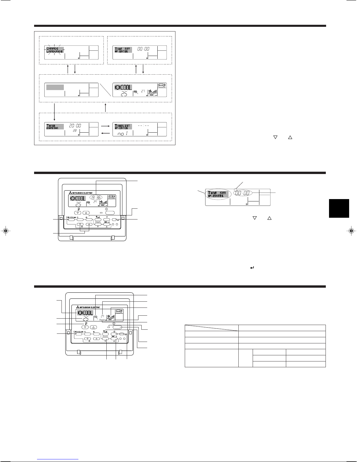
˚C
˚C
TIME SUN
PAR-21MAA
ON/OFF
FILTER
CHECK
OPERATION
CLEAR
TEST
TEMP.
MENU
BACK DAY
MONITOR/SET
CLOCK
ON/OFF
2
4
9
1
A
TIME SUN
2
3
4
˚C
˚C
PAR-21MAA
ON/OFF
FILTER
CHECK
OPERATION
CLEAR
TEST
TEMP.
MENU
BACK DAY
MONITOR/SET
CLOCK
ON/OFF
2
7
2
3
3
8
6
4
5
8
7
1
1
5
6
˚F˚C
TIMER
MON
OFF
WEEKLY
SUN MON TUE WED THU FRI SAT
WEEKLY
˚F˚C
˚C
TIME SUN
3. Bildschirmkonfiguration
Funktionsauswahl Tag/Zeit einstellen
ADC
Standardkontrollbildschirme
OFF ON
BC
Timer-Monitor Timer-Setup
B
4. Einstellen des Wochentags und der Zeit
Anzeige des Wochentags und der Zeit
<Bildschirmtypen>
Mit der Funktionsauswahl der Fernbedienung kann die Spracheinstellung des Displays auf German (Deutsch) umgestellt werden. In Abschnitt 8, Punkt [4]–1 sehen
Sie, wie Sie die Spracheinstellung ändern.
Die anfängliche Einstellung ist Englisch.
● Funktionsauswahl: Stellt die verfügbaren Funktionen und Bereiche auf der Fern-
bedienung ein (Timer-Funktionen, Betriebsbeschränkungen,
usw.).
● Tag/Zeit einstellen: Stellt den aktuellen Wochentag oder die Zeit ein.
● Standard-Kontrollbildschirme:
Zeigt den Betriebsstatus des Klimaanlagensystems und stellt
ihn ein.
● Timer-Monitor: Zeigt den aktuell eingestellten Timer an (wöchentlicher Timer,
einfacher Timer oder Auto-Off-Timer).
● Timer-Setup: Stellt den Betrieb eines der Timer ein (wöchentlicher Timer,
einfacher Timer oder Auto-Off-Timer).
<So wechseln Sie den Bildschirm>
Zu A : Halten Sie sowohl die Taste Modus als auch die Taste Timer Ein/Aus 2 Se-
kunden lang gedrückt.
Zu B :Drücken Sie die Taste Timer-Menü.
Zu C :Drücken Sie die Taste Modus (Zurück).
Zu D :Drücken Sie eine der Tasten Zeit einstellen (
oder ).
Einstellung des Wochentags
Zeit-Einstellung
Hinweis:
Der Tag und die Zeit erscheinen nicht, wenn die Uhr in der Funktionsauswahl
deaktiviert wurde.
5. Bedienung
1. Drücken Sie die Taste Zeit einstellen oder A, um 2 anzuzeigen.
2. Drücken Sie die Taste Timer Ein/Aus (Tag einstellen) 9, um den Tag einzustellen.
* Mit jedem Drücken rückt die Anzeige unter 3 einen Tag vor: Sun → Mon → ...
→ Fri → Sat.
3. Drücken Sie die entsprechende Taste Zeit einstellen A nach Bedarf, um die Zeit
einzustellen.
* Wenn Sie die Taste gedrückt halten, rückt die Zeit (unter 4) zuerst in Minuten-
intervallen vor, dann in Zehn-Minuten-Intervallen und dann in Ein-Stunden-Intervallen.
4. Nachdem Sie die entsprechenden Einstellungen unter Schritt 2 und 3 durchgeführt
haben, drücken Sie die Taste Filter
4, um die Werte zu speichern.
5.1. ON/OFF (Ein-/Ausschalten)
<So starten Sie den Betrieb>
■ Drücken Sie die Taste ON/OFF 1.
• Die Lampe EIN 1 und der Anzeigebereich erscheinen.
Hinweis:
● Wenn das Gerät neu gestartet wird, sind die Anfangseinstellungen wie folgt.
Fernbedienungseinstellungen
Modus
Temperatureinstellung
Lüftergeschwindigkeit
Luftstrom nach oben/nach unten
Letzte Einstellung
Letzte Einstellung
Letzte Einstellung
COOL oder DRY Horiz. Auslass
Modus HEAT Letzte Einstellung
FAN Horiz. Auslass
23
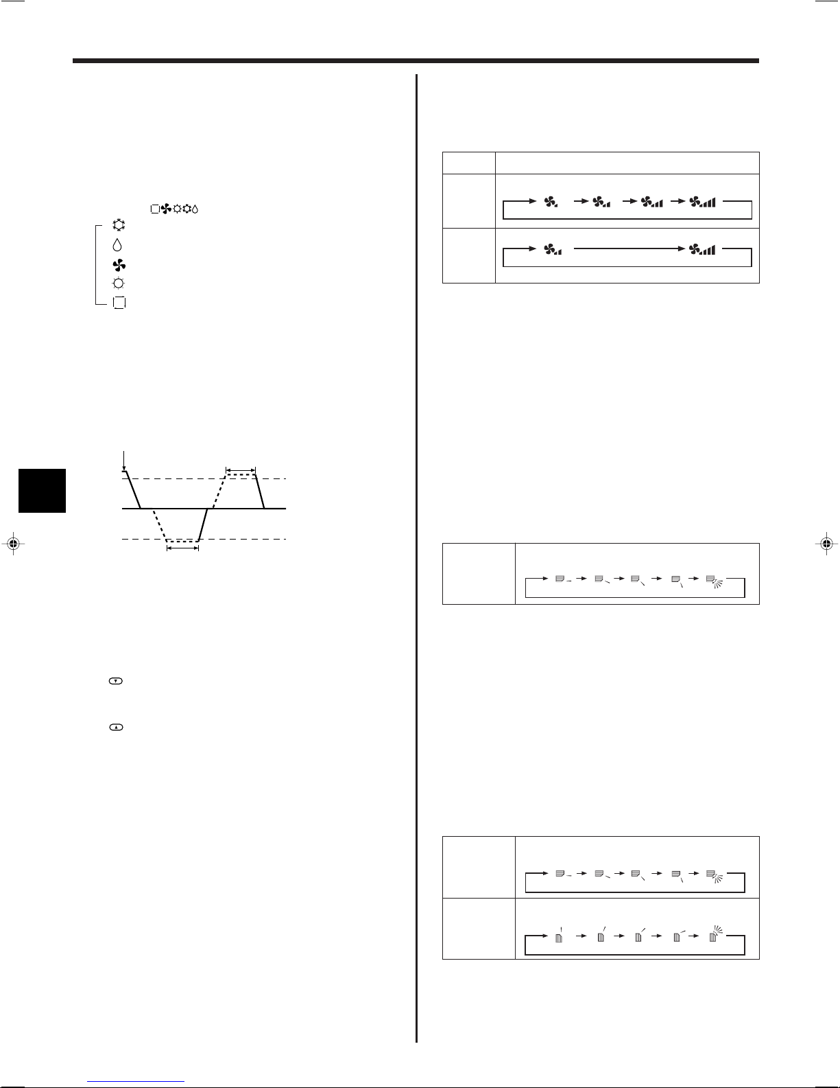
123 4
5. Bedienung
1234
123 4
<So stoppen Sie den Betrieb>
■ Drücken Sie die Taste ON/OFF 1 erneut.
• Die Lampe EIN 1 und der Display-Bereich verschwinden.
Hinweis:
Selbst wenn Sie die ON/OFF (NETZSTROM EIN/AUS-) Taste unmittelbar nach
Abschaltung des in Gang befindlichen Betriebs drücken, beginnt die Klimaanlage etwa drei Minuten lang nicht zu laufen. Dadurch wird verhindert, dass Teile im Inneren der Anlage beschädigt werden.
5.2. Betriebsart wählen
■ Die Betriebsart ( )-Taste 2 drücken und die Betriebsart wählen 2.
s
Kühlen
Trocknen
Gebläse
Heizen
Automatik (Kühlen/Heizen)
Automatischer Betrieb
■ Eine Temperatur wird eingestellt und der Kühlbetrieb beginnt, wenn die Umgebungs-
temperatur zu hoch ist bzw. der Heizbetrieb beginnt, wenn sie zu niedrig ist.
■ Im automatischen Betrieb schaltet die Klimaanlage in die Betriebsart Kühlen, wenn
die Umgebungstemperatur sich ändert und 3 Minuten lang 1,5 °C oder mehr über
der eingestellten Temperatur liegt. Ebenso schaltet die Klimaanlage in die Betriebsart Heizen, wenn die Umgebungstemperatur 3 Minuten lang 1,5 °C oder
mehr unter der eingestellten Temperatur liegt.
Kühlen
3 Minuten (schaltet von
Kühlen auf Heizen)
3 Minuten (schaltet von
Heizen auf Kühlen)
Eingestellte
Temperatur +1,5°C
Eingestellte Temperatur
Eingestellte
Temperatur –1,5°C
5.4. Einstellung der Lüftergeschwindigkeit
■ Drücken Sie die Taste Lüftergeschwindigkeit 5 so oft wie nötig, während das
System läuft.
• Jedes Drücken ändert die Stärke. Die aktuell ausgewählte Geschwindigkeit ist
unter 5 dargestellt.
• Die Änderungsreihenfolge und die verfügbaren Einstellungen sind wie folgt.
Geschwindigkeit 2
Anzeige
Geschwindigkeit 3
Geschwindigkeit 4
FAN SPEED
Modell mit 4
Geschwin-
digkeiten
Modell mit 2
Geschwin-
digkeiten
Geschwindigkeit 1
Hinweis:
● Die Anzahl der verfügbaren Lüftergeschwindigkeiten hängt von der Art des
angeschlossenen Geräts ab. Beachten Sie außerdem, dass einige Geräte
die Einstellung “Auto” nicht haben.
● In den folgenden Fällen unterscheidet sich die vom Gerät erzeugte tatsäch-
liche Lüftergeschwindigkeit von der auf der Fernbedienungsanzeige angezeigten Geschwindigkeit:
1. Während das Display “STAND BY” oder “DEFROST” anzeigt.
2. Wenn die Temperatur des Wärmetauschers in der Betriebsart Heizen zu
niedrig ist. (z.B. direkt nach dem Heizbeginn)
3. Im HEAT-Modus, wenn die Raumtemperatur höher als die Temperaturein-
stellung ist.
4. Wenn sich das Gerät im DRY-Modus befindet.
5.5. Einstellung der Luftstromrichtung
<So ändern Sie die Richtung des Luftstroms (nach oben/nach unten)>
■ Drücken Sie, während das Gerät läuft, die Taste Luftstrom nach oben/nach unten
6 nach Bedarf.
• Jedes Drücken ändert die Richtung. Die aktuelle Richtung wird unter 6 ange-
zeigt.
• Die Änderungsreihenfolge und die verfügbaren Einstellungen sind wie folgt:
Anzeig
(Horiz.) Schwing
■ Da die Umgebungstemperatur automatisch angepasst wird, um eine festgelegte
tatsächliche Temperatur beizubehalten, wird das Kühlen einige Grade wärmer und
das Heizen einige Grade kühler ausgeführt als die eingestellte Umgebungstemperatur, sobald die Temperatur erreicht ist (automatisches Energiesparen).
5.3. Temperatureinstellung
ss
s Zum Absenken der Raumtemperatur:
ss
Taste
drücken 3, um die gewünschte Raumtemperatur einzustellen.
Die eingestellte Raumtemperatur wird angezeigt 3.
ss
s Zur Erhöhung der Raumtemperatur:
ss
Taste
drücken 3, um die gewünschte Raumtemperatur einzustellen.
Die eingestellte Temperatur wird angezeigt 3.
• Folgende Temperaturbereiche sind verfügbar:
Kühlen und Trocknen: 19 - 30 °C
Heizen: 17 - 28 °C
Automatik: 19 - 28 °C
• Die Anzeige blinkt bei 8 °C bis 39 °C und informiert so darüber ob die Raumtemperatur höher oder niedriger als die angezeigte Temperatur ist.
* Beachten Sie, dass sich während dem Schwingbetrieb die Richtungsanzeige auf
dem Bildschirm nicht synchron mit den Richtungsklappen am Gerät ändert.
* Einige Modelle unterstützen Richtungseinstellungen nicht.
Hinweis:
● Die verfügbaren Richtungen hängen von der Art des angeschlossenen Ge-
räts ab. Beachten Sie außerdem, dass einige Geräte die Einstellung “Auto”
nicht haben.
● In den folgenden Fällen unterscheidet sich die tatsächliche Luftrichtung von
der Richtung, die auf der Fernbedienungsanzeige angezeigt wird:
1. Während das Display “STAND BY” oder “DEFROST” anzeigt.
2. Sofort nach Starten des Heizmodus (während das System darauf wartet,
dass sich der Modus ändert).
3. Im Heizmodus, wenn die Raumtemperatur höher als die Temperaturein-
stellung ist.
(Bei Geräten der Serie PFFY-P·VKM)
● Bei Geräten der Serie PFFY-P·VKM weicht die auf der Fernbedienung ange-
zeigte Luftstromrichtung von der tatsächlichen Luftstromrichtung ab. Beachten Sie hierzu folgende Tabelle.
Anzeig
Aktuell
(Horiz.) Schwing
(Horiz.) Schwing
● Die Luftstromrichtung des Dämpfer des unteren Luftauslasses lässt sich nicht
einstellen. Die Luftstromrichtung wird automatisch über einen Computer
geregelt.
24
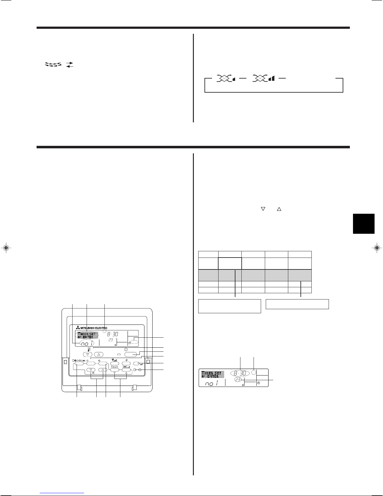
˚C
SUN
ON
WEEKLY
PAR-21MAA
ON/OFF
FILTER
CHECK
OPERATION
CLEAR
TEST
TEMP.
MENU
BACK DAY
MONITOR/SET
CLOCK
ON/OFF
2
42 3
A9 78
0
4
1
3
B
1
5. Bedienung
˚C
SUN
ON
WEEKLY
6
7
5
<So ändern Sie die Luftrichtung (nach links/nach rechts)>
■ Drücken Sie die Taste Luftklappe 7 nach Bedarf.
• Das Bild Luftklappe 7 erscheint.
Mit jedem Drücken der Taste wird die Einstellung wie folgt umgeschaltet.
Keine Anzeige
(Stopp)
(ON) (OFF)
Während dem Schwingbetrieb bewegt sich
die Pfeilanzeige von links nach rechts.
5.6. Belüftung
ss
s Für LOSSNAY-Kombination
ss
5.6.1. Für verdrahteter Fernbedienung
● So betreiben Sie den Ventilator zusammen mit dem Innengerät:
■ Drücken Sie die Taste ON/OFF 1.
• Die Anzeige Vent erscheint auf dem Bildschirm (unter 8). Der Ventilator
arbeitet jetzt immer automatisch, wenn das Innengerät läuft.
6. Timer
6.1. Für verdrahteter Fernbedienung
Sie können die Funktionsauswahl verwenden, um auszuwählen, welchen der drei
Timer Sie verwenden möchten: 1 Wöchentlicher Timer, 2 Einfacher Timer oder 3
Auto-Off-Timer.
6.1.1. Wöchentlicher Timer
■ Der wöchentliche Timer kann verwendet werden, um bis zu acht Betriebsarten für
jeden Tag der Woche einzustellen.
• Jede Betriebsart kann aus Folgendem bestehen: EIN/AUS-Zeit zusammen mit
einer Temperatureinstellung oder nur EIN/AUS-Zeit oder nur Temperatureinstellung.
• Wenn die aktuelle Zeit eine vom Timer eingestellte Zeit erreicht, führt die
Klimaanlage die vom Timer eingestellte Aktion durch.
■ Die Einteilung der Zeiteinstellung für diesen Timer ist 1 Minute.
Hinweis:
*1. Die wöchentliche Timer/einfache Timer/Auto-Off-Timer können nicht gleich-
zeitig eingestellt werden.
*2. Der wöchentliche Timer funktioniert nicht, wenn eine der folgenden Bedin-
gungen wirksam ist.
Die Timerfunktion ist ausgeschaltet; das System befindet sich in einem
unnormalen Zustand; ein Testlauf wird durchgeführt; die Fernbedienung
führt einen Selbstcheck oder einen Fernbedienungscheck durch; der Benutzer stellt gerade eine Funktion ein; der Benutzer stellt gerade einen Timer
ein; der Benutzer stellt gerade den aktuellen Wochentag oder die Zeit ein;
das System wird zentral gesteuert. (Das System führt insbesondere dann
keine Betriebsarten durch (Gerät ein, Gerät aus oder Temperatureinstellung),
die während diesen Bedingungen deaktiviert sind.)
Betriebsart Nr.
Tageseinstellung
● So betreiben Sie den Ventilator nur, wenn das Innengerät ausgeschaltet ist:
■ Drücken Sie die Taste Belüftung 8, während das Innengerät ausgeschaltet ist.
• Die Lampe Ein (unter 1) und die Anzeige Belüftung (unter 8) erscheinen.
● So ändern Sie die Ventilatorstärke:
■ Drücken Sie die Taste Belüftung 8 nach Bedarf.
• Mit jedem Drücken wird die Einstellung wie unten dargestellt umgeschaltet.
▲
(Niedrig) (Hoch)
▲
▲
Keine Anzeige (Stopp)
(OFF)
Hinweis:
● Bei einigen Modellkonfigurationen kann sich der Lüfter des Innengeräts ein-
schalten, auch wenn Sie den Ventilator so eingestellt haben, dass er unabhängig läuft.
<So stellen Sie den wöchentlichen Timer ein>
1. Achten Sie darauf, dass Sie sich im Standardkontrollbildschirm befinden und dass
die Anzeige für den wöchentlichen Timer 1 auf dem Display angezeigt wird.
2. Drücken Sie die Taste Timer-Menü B, so dass “Set Up” auf dem Bildschirm
erscheint (unter 2). (Beachten Sie, dass mit jedem Tastendruck die Anzeige
zwischen “Set Up” und “Monitor” umgeschaltet wird.)
3. Drücken Sie die Taste Timer Ein/Aus (Tag einstellen) 9, um den Tag einzustel-
len. Mit jedem Drücken geht die Anzeige unter 3 zur nächsten Einstellung in der
folgenden Reihenfolge: “Sun Mon Tues Wed Thurs Fri Sat” → “Sun” → ... → “Fri”
→ “Sat” → “Sun Mon Tues Wed Thurs Fri Sat”...
4. Drücken Sie die Taste Betrieb
oder (7 oder 8) so oft wie nötig, um die
entsprechende Betriebsnummer auszuwählen (1 bis 8) 4.
* Mit Ihren Eingaben unter Schritt 3 und 4 wählen Sie eine der Zellen aus der
unten dargestellten Matrix.
(Die Fernbedienungsanzeige auf der linken Seite zeigt, wie das Display
aussieht, wenn Betrieb 1 für Sonntag auf die unten angegebenen Werte
eingestellt ist.)
Setup-Matrix
Betr.-Nr. Sunday Monday … Saturday
• 8:30
• ON
No. 1
• 23 °C
• 10:00
No. 2
• OFF
…
No. 8
<Einstellungen von Betrieb 1 für Sonntag>
Klimaanlage um 8.30 Uhr mit auf 23 °C
eingestellter Temperatur star ten.
• 10:00
• OFF
▲
• 10:00
• OFF
• 10:00
• OFF
▲
<Einstellung von Betrieb 2 für jeden Tag>
Klimaanlage um 10.00 Uhr ausschalten.
Hinweis:
Durch Einstellen des Tags auf “Sun Mon Tues Wed Thurs Fri Sat”, können Sie
festlegen, dass derselbe Betrieb jeden Tag zur selben Zeit durchgeführt wird.
(Beispiel: Betrieb 2 oben, der für jeden Tag der Woche gleich ist.)
<Einstellen des wöchentlichen Timers>
Zeigt die
Zeiteinstellung an
Zeigt die ausgewählte Betriebsart an (EIN oder AUS)
* Erscheint nicht, wenn die Betriebsart nicht einge-
stellt ist.
Zeigt die Temperatureinstellung an
* Erscheint nicht, wenn die Tempera-
tur nicht eingestellt ist.
5. Drücken Sie die entsprechende Taste Zeit einstellen A so oft wie nötig, um die
gewünschte Zeit einzustellen (unter 5).
* Wenn Sie die Taste gedrückt halten, rückt die Zeit zuerst in Minutenintervallen,
dann in Zehn-Minuten-Intervallen und dann in Ein-Stunden-Intervallen vor.
6. Drücken Sie die Taste ON/OFF 1, um die gewünschte Betriebsart auszuwählen
(EIN oder AUS) unter 6.
* Jedes Drücken ändert die nächste Einstellung in der folgenden Reihenfolge:
keine Anzeige (keine Einstellung) → “ON” → “OFF”.
25
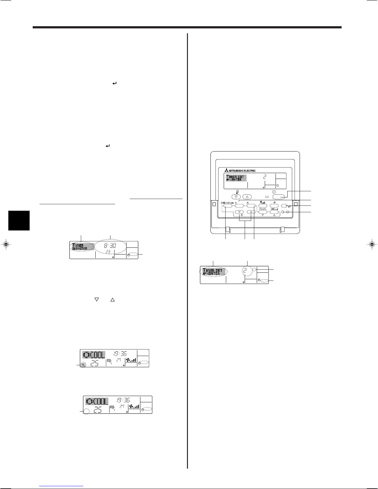
ONHr
AFTER
SIMPLE
PAR-21MAA
ON/OFF
FILTER
CHECK
OPERATION
CLEAR
TEST
TEMP.
MENU
BACK DAY
MONITOR/SET
CLOCK
ON/OFF
2A9
0
4
1
B
ONHr
AFTER
SIMPLE
4
1
3
2
˚C
TIMER
SUN
ON
OFF
WEEKLY
1
9
8
˚C
˚C
TIME SUN
WEEKLY
0
˚C
˚C
TIME SUN
WEEKLY
0
6. Timer
7. Drücken Sie die entsprechende Taste Temperatur einstellen 3, um die gewünschte
Temperatur einzustellen (unter 7).
* Jedes Drücken ändert die Einstellung in der folgenden Reihenfolge: keine An-
zeige (keine Einstellung) ⇔ 24 ⇔ 25 ⇔ ... ⇔ 29 ⇔ 30 ⇔ 12 ⇔ ... ⇔ 23 ⇔
keine Anzeige.
(Verfügbarer Bereich: Der Bereich für die Einstellung ist 12 °C bis 30 °C. Der
tatsächliche Bereich, über den die Temperatur gesteuert werden kann, variiert
jedoch entsprechend des Typs des angeschlossenen Geräts.)
8. Nachdem Sie die entsprechenden Einstellungen unter Schritt 5, 6 und 7 durchgeführt haben, drücken Sie die Taste Filter
4, um die Werte zu speichern.
Um die aktuell eingestellten Werte für den ausgewählten Betrieb einzustellen,
drücken Sie die Taste Check (Löschen) 0 einmal kurz.
* Die angezeigte Zeiteinstellung ändert sich zu “—:—” und die Ein/Aus- und
Temperatureinstellungen verschwinden.
(Um alle wöchentlichen Timer-Einstellungen gleichzeitig zu löschen, halten Sie
die Taste Check (Löschen) 0 mindestens zwei Sekunden lang gedrückt. Das
Display beginnt zu blinken, wodurch angezeigt wird, dass alle Einstellungen
gelöscht wurden.)
Hinweis:
Ihre neuen Einträge werden storniert, wenn Sie die Taste Modus (Zurück) 2
drücken, bevor Sie die Taste Filter
4 drücken.
Wenn Sie zwei oder mehr unterschiedliche Betriebsarten für genau dieselbe Zeit eingestellt haben, wird nur die Betriebsart mit der höchsten Betriebsart-Nr. ausgeführt.
9. Wiederholen Sie die Schritte 3 bis 8 nach Bedarf, um so viele der verfügbaren
Zellen auszufüllen, wie Sie möchten.
10. Drücken Sie die Taste Modus (Zurück) 2, um zum Standardkontrollbildschirm
zurückzukehren und den Einstellvorgang zu beenden.
11. Um den Timer zu aktivieren, drücken Sie die Taste Timer Ein/Aus 9, so dass die
Anzeige “Timer Off” vom Bildschirm verschwindet.
Achten Sie darauf, dass die
Anzeige “Timer Off” verschwunden ist.
* Wenn es keine Timer-Einstellungen gibt, blinkt die Anzeige “Timer Off” auf
dem Bildschirm.
<So zeigen Sie den wöchentlichen Timer an>
Timer-Einstellungen
6.1.2. Einfacher Timer
■ Sie haben drei Möglichkeiten, den einfachen Timer einzustellen.
• Nur Startzeit:
Die Klimaanlage startet, wenn die eingestellte Zeit vergangen ist.
• Nur Stopzeit:
Die Klimaanlage stoppt, wenn die eingestellte Zeit vergangen ist.
• Start- und Stopzeiten:
Die Klimaanlage startet und stoppt, wenn die entsprechenden Zeiten vergangen sind.
■ Der einfache Timer (Start und Stopp) kann nur einmal innerhalb eines Zeitraums
von 72 Stunden eingestellt werden. Die Zeiteinstellung erfolgt in Stunden-Schritten.
Hinweis:
*1. Die wöchentliche Timer/einfache Timer/Auto-Off-Timer können nicht gleich-
zeitig eingestellt werden.
*2. Der einfache Timer funktioniert nicht, wenn eine der folgenden Bedingun-
gen wirksam ist:
Die Timerfunktion ist ausgeschaltet; das System befindet sich in einem
unnormalen Zustand; ein Testlauf wird durchgeführt; die Fernbedienung
führt einen Selbstcheck oder eine Diagnose durch; der Benutzer wählt gerade eine Funktion aus; der Benutzer stellt gerade den Timer ein; das System wird zentral gesteuert. (Unter diesen Bedingungen ist der Ein/AusBetrieb deaktiviert.)
1. Achten Sie darauf, dass die wöchentliche Timer-Anzeige auf dem Bildschirm sichtbar ist (unter 1).
2. Drücken Sie die Taste Timer-Menü B, so dass “Monitor” auf dem Bildschirm er-
scheint (unter 8).
3. Drücken Sie die Taste Timer Ein/Aus (Tag einstellen) 9 so oft wie nötig, um den
Tag einzustellen, den Sie anzeigen möchten.
4. Drücken Sie die Taste Betrieb
oder (7 oder 8) so oft wie nötig, um den
auf dem Display angezeigten Timer-Betrieb zu ändern (unter 9).
* Mit jedem Drücken gelangen Sie zur nächsten Timer-Betriebsart in der Rei-
henfolge der Zeiteinstellung.
5. Um den Monitor zu schließen und zum Standardkontrollbildschirm zurückzukeh-
ren, drücken Sie die Taste Modus (Zurück) 2.
<So schalten Sie den wöchentlichen Timer aus>
Drücken Sie die Taste Timer Ein/Aus 9, so dass “Timer Off” unter 0 erscheint.
<So schalten Sie den wöchentlichen Timer ein>
Drücken Sie die Taste Timer Ein/Aus 9, so dass die Anzeige “Timer Off” (unter 0)
verschwindet.
26
<So stellen Sie den einfachen Timer ein>
Timer-Einstellung
Aktion (Ein oder Aus)
* “— —” wird angezeigt, wenn
es keine Einstellung gibt.
1. Achten Sie darauf, dass Sie sich im Standardkontrollbildschirm befinden und dass
die Anzeige des einfachen Timers auf dem Display angezeigt wird (unter 1).
Wenn etwas anderes als der einfache Timer angezeigt wird, stellen Sie den SIMPLE TIMER mit Hilfe der Timer-Funktionseinstellung der Funktionsauswahl ein
(siehe 8.[4]–3 (3)).
2. Drücken Sie die Taste Timer-Menü B, so dass “Set Up” auf dem Bildschirm er-
scheint (unter 2). (Beachten Sie, dass mit jedem Tastendruck die Anzeige zwischen “Set Up” und “Monitor” umgeschaltet wird.)
3. Drücken Sie die Taste ON/OFF 1, um die aktuelle EIN- oder AUS-Einstellung des
einfachen Timers anzuzeigen. Drücken Sie die Taste einmal, um die restliche Zeit
unter EIN anzuzeigen, und dann noch einmal, um die restliche Zeit unter AUS
anzuzeigen. (Die Anzeige EIN/AUS erscheint unter 3.)
•“EIN”-Timer: Die Klimaanlage startet den Betrieb, wenn die angegebene An-
zahl Stunden vergangen ist.
•“AUS”-Timer: Die Klimaanlage stoppt den Betrieb, wenn die angegebene An-
zahl Stunden vergangen ist.
4. Wenn “ON” oder “OFF” unter 3 angezeigt wird: Drücken Sie die entsprechende
Taste Zeit einstellen A so oft wie nötig, um die Stunden auf EIN (falls “ON”
angezeigt wird) oder die Stunden auf AUS (falls “OFF” angezeigt wird) unter 4
einzustellen.
• Verfügbarer Bereich: 1 bis 72 Stunden
5. Um sowohl die Zeiten für EIN als auch für AUS einzustellen, wiederholen Sie die
Schritte 3 und 4.
* Beachten Sie, dass die AUS- und EIN-Zeiten nicht auf denselben Wert einge-
stellt werden können.
6. So löschen Sie die aktuelle EIN- oder AUS-Einstellung: Zeigen Sie die EIN- oder
AUS-Einstellung (siehe Schritt 3) an und drücken Sie dann die Taste Check
(Löschen) 0, so dass die Zeiteinstellung zu “—” unter 4 zurückkehrt. (Wenn Sie
nur eine EIN-Einstellung oder nur eine AUS-Einstellung verwenden wollen, achten
Sie darauf, dass die Einstellung, die Sie nicht verwenden möchten, als “—”
angezeigt wird.)
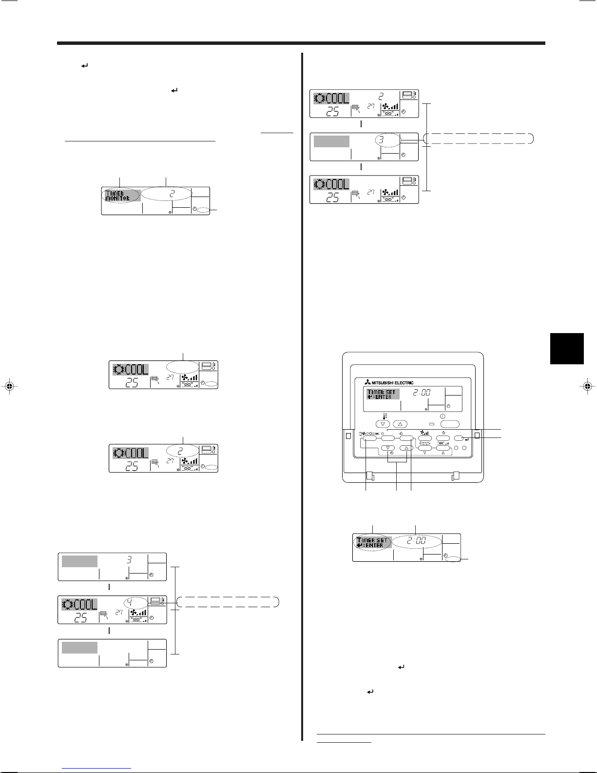
TIMER ON
OFFHrAFTER
SIMPLE
1
6
5
˚C
˚C
SIMPLE
7
˚C
˚C
ONHr
AFTER
SIMPLE
7
ONHr
AFTER
SIMPLE
˚C
˚C
OFFHrAFTER
SIMPLE
SIMPLE
˚C
˚C
OFFHrAFTER
SIMPLE
ONHr
AFTER
SIMPLE
˚C
˚C
SIMPLE
AFTER OFF
AUTO OFF
PAR-21MAA
ON/OFF
FILTER
CHECK
OPERATION
CLEAR
TEST
TEMP.
MENU
BACK DAY
MONITOR/SET
CLOCK
ON/OFF
2A9
4
B
AFTER OFF
AUTO OFF
3
1
2
6. Timer
7. Nach Durchführung der oben angegebenen Schritte 3 bis 6 drücken Sie die Taste
Filter
4, um den Wert zu speichern.
Hinweis:
Ihre neuen Einstellungen werden storniert, wenn Sie die Taste Modus (Zurück)
2 drücken, bevor Sie die Taste Filter
4 drücken.
8. Drücken Sie die Taste Modus (Zurück) 2, um zum Standardkontrollbildschirm
zurückzukehren.
9. Drücken Sie die Taste Timer Ein/Aus 9, um den Timer-Count-down zu starten.
Wenn der Timer läuft, wird der Timer-Wert auf dem Display angezeigt.
Achten Sie
darauf, ob der Timer-Wert sichtbar und richtig ist.
<Anzeigen der aktuellen Einstellungen des einfachen Timers>
Timer-Einstellung
1. Achten Sie darauf, dass die Anzeige des einfachen Timers auf dem Bildschirm
sichtbar ist (unter 1).
2. Drücken Sie die Taste Timer-Menü B, so dass “Monitor” auf dem Bildschirm er-
scheint (unter 5).
• Falls der einfache EIN- oder AUS-Timer läuft, erscheint der aktuelle Timer-Wert
unter 6.
• Falls die EIN- und AUS-Werte beide eingestellt wurden, erscheinen beide Werte
abwechselnd.
3. Drücken Sie die Taste Modus (Zurück) 2, um die Monitoranzeige zu schließen und
zum Standardkontrollbildschirm zurückzukehren.
<So schalten Sie den einfachen Timer aus...>
Drücken Sie die Taste Timer Ein/Aus 9, so dass die Timer-Einstellung nicht mehr auf
dem Bildschirm erscheint (unter 7).
Beispiel 2:
Starten Sie den Timer, wobei die AUS-Zeit vor der EIN-Zeit liegt.
EIN-Einstellung: 5 Stunden
AUS-Einstellung: 2 Stunden
Beim Timer-Start
Das Display zeigt die AUS-Einstellung des
▲
Timers (Stunden bleiben AUS).
2 Stunden nach dem Timer-Start
Das Display wechselt zur Anzeige der EINEinstellung des Timers (Stunden bleiben EIN).
▲
Die angezeigte Zeit entspricht der Einstellung
EIN (5 Stunden) – Einstellung AUS (2 Stunden)
= 3 Stunden.
5 Stunden nach dem Timer-Start
Die Klimaanlage schaltet sich ein und läuft weiter, bis sie jemand ausschaltet.
6.1.3. Timer für automatisches Ausschalten
■ Dieser Timer beginnt den Count-down, wenn die Klimaanlage startet, und schaltet
die Klimaanlage aus, wenn die eingestellte Zeit abgelaufen ist.
■ Die verfügbaren Einstellungen gehen in 30-Minuten-Intervallen von 30 Minuten bis
zu 4 Stunden.
Hinweis:
*1. Die wöchentliche Timer/einfache Timer/Auto-Off-Timer können nicht gleich-
zeitig eingestellt werden.
*2. Der Auto-Off-Timer funktioniert nicht, wenn eine der folgenden Bedingun-
gen wirksam ist:
Die Timerfunktion ist ausgeschaltet; das System befindet sich in einem
unnormalen Zustand; ein Testlauf wird durchgeführt; die Fernbedienung
führt einen Selbstcheck oder eine Diagnose durch; der Benutzer wählt gerade eine Funktion aus; der Benutzer stellt gerade den Timer ein; das System wird zentral gesteuert. (Unter diesen Bedingungen ist der Ein/AusBetrieb deaktiviert.)
<So starten Sie den einfachen Timer...>
Drücken Sie die Taste Timer Ein/Aus 9, so dass die Timer-Einstellungen unter 7
sichtbar sind.
Beispiele
Falls die EIN- und AUS-Zeiten beide im einfachen Timer eingestellt wurden, werden
der Betrieb und die Anzeige wie unten dargestellt.
Beispiel 1:
Starten Sie den Timer, wobei die EIN-Zeit früher als die AUS-Zeit eingestellt ist.
EIN-Einstellung: 3 Stunden
AUS-Einstellung:7 Stunden
Beim Timer-Start
Das Display zeigt die EIN-Einstellung des
▲
Timers (Stunden bleiben EIN).
3 Stunden nach dem Timer-Start
Die Anzeige wechselt zur Anzeige der AUSEinstellung des Timers (Stunden bleiben AUS).
▲
Die angezeigte Zeit entspricht der Einstellung
AUS (7 Stunden) – Einstellung EIN (3 Stunden)
= 4 Stunden.
7 Stunden nach dem Timer-Start
Die Klimaanlage schaltet sich aus und bleibt
aus, bis sie von jemandem erneut gestartet
wird.
<So stellen Sie den Auto-Off-Timer ein>
Timer-Einstellung
1. Achten Sie darauf, dass Sie sich im Standardkontrollbildschirm befinden und dass
die Anzeige “Auto Off Timer” auf dem Display angezeigt wird (unter 1).
Wenn etwas anderes als der Auto-Off-Timer angezeigt wird, stellen Sie den AUTOOFF-TIMER mit Hilfe der Timer-Funktionseinstellung der Funktionsauswahl ein
(siehe 8.[4]–3 (3)).
2. Halten Sie die Taste Timer-Menü B 3 Sekunden lang gedrückt, so dass “Set Up”
auf dem Bildschirm erscheint (unter 2).
(Beachten Sie, dass mit jedem Tastendruck die Anzeige zwischen “Set Up” und
“Monitor” umgeschaltet wird.)
3. Drücken Sie die entsprechende Taste Zeit einstellen A so oft wie nötig, um die OFF-
Zeit einzustellen (unter 3).
4. Drücken Sie die Taste Filter
4, um die Einstellung zu speichern.
Hinweis:
Ihr Eintrag wird storniert, wenn Sie die Taste Modus (Zurück) 2 drücken, bevor
Sie die Taste Filter
4 drücken. drücken.
5. Drücken Sie die Taste Modus (Zurück) 2, um den Einstellvorgang zu beenden und
zum Standardkontrollbildschirm zurückzukehren.
6. Falls die Klimaanlage bereits läuft, beginnt der Timer sofort mit dem Count-down.
Achten Sie darauf, zu überprüfen, ob die Timer-Einstellung richtig auf dem
Display erscheint.
27
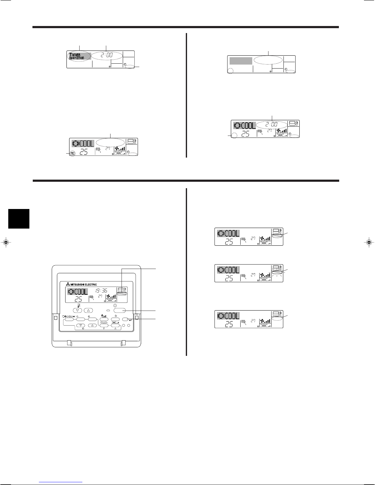
AFTER
TIMER
OFF
AUTO OFF
5
1
4
˚C
˚C
AUTO OFF
6
7
AUTO OFF
7
˚C
˚C
AFTER OFF
AUTO OFF
6
7
˚C
˚C
TIME SUN
FUNCTION
PAR-21MAA
ON/OFF
FILTER
CHECK
OPERATION
CLEAR
TEST
TEMP.
MENU
BACK DAY
MONITOR/SET
CLOCK
ON/OFF
4
1
1
˚C
˚C
FUNCTION
1
˚C
˚C
FUNCTION
1
˚C
˚C
1
6. Timer
<Überprüfen der aktuellen Einstellung des Auto-Off-Timers>
Timer-Einstellung
1. Achten Sie darauf, dass “Auto Off” auf dem Bildschirm sichtbar ist (unter 1).
2. Halten Sie die Taste Timer-Menü B 3 Sekunden lang gedrückt, so dass “Monitor”
auf dem Bildschirm angegeben wird (unter 4).
• Der Timer, der noch beendet werden muss, erscheint unter 5.
3. Um den Monitor zu schließen und zum Standardkontrollbildschirm zurückzukeh-
ren, drücken Sie die Taste Modus (Zurück) 2.
<So schalten Sie den Auto-Off-Timer aus...>
● Halten Sie die Taste Timer Ein/Aus 9 3 Sekunden lang gedrückt, so dass “Timer
Off” erscheint (unter 6) und der Timer-Wert (unter 7) verschwindet.
7. Weitere Funktionen
7.1. Sperren der Fernbedienungstasten (Beschränkung
der Betriebsfunktionen)
■ Wenn Sie möchten, können Sie die Tasten der Fernbedienung sperren. Sie können
die Funktionsauswahl der Fernbedienung verwenden, um auszuwählen, welche
Art von Sperre Sie verwenden möchten. (Informationen zur Auswahl des Sperrtyps
finden Sie in Abschnitt 8, Punkt [4]–2 (1).)
Sie können eine der zwei folgenden Sperrarten verwenden:
1 Alle Tasten sperren: Sperrt alle Tasten auf der Fernbedienung.
2 Alle außer EIN/AUS sperren: Sperrt alle Tasten außer der Taste ON/OFF.
Hinweis:
Die Sperr-Anzeige erscheint auf dem Bildschirm, um anzugeben, dass die Tasten zurzeit gesperrt sind.
● Oder schalten Sie die Klimaanlage selbst aus. Der Timer-Wert (unter 7) verschwin-
det vom Bildschirm.
<So starten Sie den Auto-Off-Timer...>
● Halten Sie die Taste Timer Aus/Ein 9 3 Sekunden lang gedrückt. Die Anzeige
“Timer Off” erscheint (unter 6) und die Timer-Einstellung erscheint auf dem Display
(unter 7).
● Oder schalten Sie die Klimaanlage ein. Der Timer-Wert erscheint unter 7.
<So sperren Sie die Tasten>
1. Halten Sie die Taste Filter 4 zusammen mit der Taste ON/OFF 1 2 Sekunden lang
gedrückt. Die Sperr-Anzeige erscheint auf dem Bildschirm (unter 1) und zeigt an,
dass die Sperre jetzt aktiv ist.
* Wenn das Sperren in der Funktionsauswahl deaktiviert wurde, zeigt der Bild-
schirm die Meldung “Not Available” an, wenn Sie die Tasten wie oben beschrie-
ben drücken.
• Wenn Sie eine gesperrte Taste drücken, blinkt die Sperr-Anzeige (unter 1) auf
dem Display.
28
Sperr-Anzeige
<So entsperren Sie die Tasten>
1. Halten Sie die Taste Filter 4 zusammen mit der Taste ON/OFF 1 2 Sekunden lang
gedrückt – die Sperr-Anzeige verschwindet vom Bildschirm (unter 1).
ON/OFF
˚C
˚C
ERROR CODE
ON/OFF
CALL:XXXX
XXX:XXX
7. Weitere Funktionen
ON/OFF
ERROR CODE
7.2. Anzeige von Fehlercodes
Lampe EIN
(blinkt)
Gerät-Nr.
Wenn Sie eine Telefonnummer eingegeben haben, die bei Auftreten eines Problems angerufen werden
sollte, zeigt der Bildschirm diese Nummer an. (Sie können dies in der Funktionsauswahl einrichten.
Informationen dazu finden Sie in Abschnitt 8.)
● Falls sowohl die Lampe EIN als auch der Fehlercode blinken: Dies bedeutet, dass die Klimaanlage gestört ist und der Betrieb gestoppt wurde (und nicht wieder aufgenommen
werden kann). Notieren Sie sich die angegebene Gerätenummer und den Fehlercode und schalten Sie dann die Netztaste der Klimaanlage aus und rufen Sie Ihren Händler
oder Servicetechniker.
● Wenn nur der Fehlercode blinkt (während die Lampe EIN leuchtet): Der Betrieb läuft weiter, es kann jedoch ein Problem mit dem System vorliegen. In diesem Fall sollten Sie
den Fehlercode notieren und Ihren Händler oder Servicetechniker um Rat fragen.
* Falls Sie eine Telefonnummer eingegeben haben, die bei Auftreten eines Problems angerufen werden soll, drücken Sie die Taste Check und die Nummer wird auf dem
Bildschirm angezeigt. (Sie können dies in der Funktionsauswahl einrichten. Informationen dazu finden Sie in Abschnitt 8.)
Fehlercode
Wenn die Taste Check gedrückt ist:
Fehlercode
8. Funktionsauswahl
Funktionsauswahl an der Fernbedienung
Die Einstellung der folgenden Fernbedienungsfunktionen kann mit dem Auswahlmodus der Fernbedienungsfunktion geändert werden. Ändern Sie die Einstellung nach Bedarf.
Eintrag 1
1. Sprache ändern
(“CHANGE
LANGUAGE”)
2. Funktionsgrenzen
(“Funktion auswählen”)
3. Auswahl der
Betriebsart
(“Betriebsart
wählen”)
4. Änderung der
Anzeige
(“Anzeige Betriebsart”)
Eintrag 2
Einstellung der angezeigten Sprache
(1) Einstellung der Funktionsgrenzen bei der Bedienung (Operati-
on Lock) (“Sperr-Funktion”)
(2) Einstellung der Benutzung der Betriebsart Automatisch (“Aus-
wahl Autobetrieb”)
(3) Einstellung der Temperaturgrenzen (“Limit temp Funktion”)
(1) Haupt-/Nebenfunktion der Fernbedienung (“Haupt-/
Nebencontroller”)
(2) Benutzung der Uhreinstellung (“Uhr”)
(3) Einstellung der Timer-Funktion (“Wochenzeit Schaltuhr”)
(4) Kontaktnummer für den Fall von Fehlfunktionen (“CALL.”)
(1) Temperatureinstellung in °C/°F (“Wechsel °C/°F”)
(2) Einstellung der Anzeige der Luftansaugtemperatur (“Raum
TEMP gewählt”)
(3) Einstellung der automatischen Kühl-/Heizanzeige (“Autobetrieb
C/H”)
• Anzeige in mehreren Sprachen ist möglich
• Einstellung der Funktionsgrenzen bei der Bedienung (Operation Lock)
• Einstellung, ob die Betriebsart “Automatisch” benutzt wird oder nicht
• Einstellung des Temperaturbereichs (Maximum, Minimum)
• Auswahl der Funktion als Haupt-/Nebenfernbedienung
* Wenn zwei Fernbedienungen in einer Gruppe angeschlossen sind, muss
eine der beiden als Nebengerät arbeiten.
• Einstellung, ob die Uhrfunktionen benutzt werden oder nicht
• Einstellen des Timer-Typs
• Anzeige der Kontaktnummer für den Fall von Fehlfunktionen
• Einstellen der Telefonnummer
• Einstellen der Temperatureinheit der Anzeige (°C oder °F)
• Einstellung, ob die Temperatur der (angesaugten) Innenluft angezeigt wird
oder nicht
• Einstellung, ob “Cooling” oder “Heating” (Kühlen/Heizen) in der Betriebsart Automatisch angezeigt werden oder nicht
Eintrag 3 (Inhalt der Einstellungen)
29
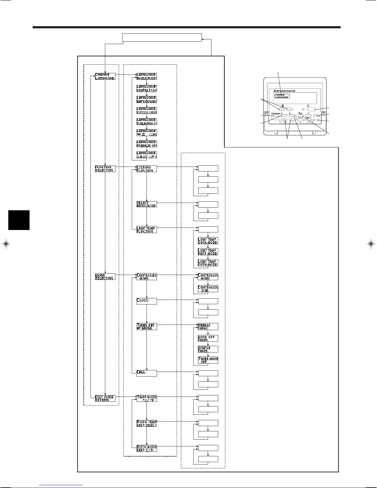
OFF
on1
on2
OFF
ON
OFF
ON
OFF
OFF
CALL-
ON
OFF
ON
OFF
°C
°F
PAR-21MAA
ON/OFF
FILTER
CHECK
OPERATION
CLEAR
TEST
TEMP.
MENU
BACK DAY
MONITOR/SET
CLOCK
ON/OFF
F
E
G
C
D
H
B
A
I
G
G
G
G
G
G
E
E
G
G
G
G
G
E
G
E
G
G
G
G
D
D
D
D
D
D
D
D
D
D
D
D
D
D
D
D
D
D
D
D
D
D
D
D
D
D
D
D
D
D
English
Germany
Spanish
Russian
Italy
Chinese
French
Japanese
8. Funktionsauswahl
[Flussdiagramm der Funktionsauswahl]
Spracheinstellung (Englisch)
Sprache
ändern
Funktion
auswählen
Betriebsart
wählen
Halten Sie die Taste E gedrückt und drücken Sie Taste D zwei
Sekunden lang.
Funktionsauswahlmodus der Fernbedienung
Eintrag 1 Eintrag 2
Normalbetriebsanzeige
(Anzeige bei deaktivierter Klimaanlage)
Halten Sie die Taste E gedrückt und drücken Sie Taste D zwei Sekunden lang.
E Drücken Sie die Taste für die Betriebsart.
G Drücken Sie die Taste TIMER MENU (TIMER-MENÜ).
D Drücken Sie die Taste TIMER ON/OFF (TIMER EIN/AUS).
Punktmatrixanzeige
Eintrag 3
Einstellung für die Bedienungssperre wird nicht benutzt.
(Anfänglicher Einstellungswert)
Bedienungssperre außer für Taste On/Off.
Bedienungssperre für alle Tasten.
Die Betriebsart Automatisch wird angezeigt, wenn die Betriebsart
gewählt wird. (Anfänglicher Einstellungswert)
Die Betriebsart Automatisch wird nicht angezeigt, wenn die Betriebsart gewählt wird.
Die Temperaturbereichsgrenzen sind nicht aktiv. (Anfänglicher Einstellungswert)
Der Temperaturbereich kann in der Betriebsart Kühlen/Trocken geändert werden.
Der Temperaturbereich kann in der Betriebsart Heizen geändert
werden.
Der Temperaturbereich kann in der Betriebsart Automatisch geändert
werden.
Die Fernbedienung fungiert als Hauptfernbedienung. (Anfänglicher
Einstellungswert)
Die Fernbedienung fungiert als Nebenfernbedienung.
Anzeige
Betriebsart
30
Die Uhrfunktion kann benutzt werden. (Anfänglicher Einstellungswert)
Die Uhrfunktion kann nicht benutzt werden.
Der wöchentliche Timer kann benutzt werden. (Anfänglicher Einstellungswert)
Der Timer für automatisches Ausschalten kann benutzt werden.
Der einfache Timer kann benutzt werden.
Betriebsart Timer kann nicht benutzt werden.
Die eingestellten Kontaktnummern werden im Falle von Fehlern nicht
angezeigt. (Anfänglicher Einstellungswert)
Die eingestellten Kontaktnummern werden im Falle von Fehlern
angezeigt.
Die Temperatureinheit °C wird verwendet. (Anfänglicher Einstellungswert)
Die Temperatureinheit °F wird verwendet.
Die Umgebungstemperatur wird angezeigt. (Anfänglicher Einstellungswert)
Die Umgebungstemperatur wird nicht angezeigt.
Entweder “Automatic cooling” (automatisches Kühlen) oder “Automatic
heating” (automatisches Heizen) wird angezeigt, wenn die Betriebsart Automatisch gewählt wurde. (Anfänglicher Einstellungswert)
Nur “Automatic” (automatisch) wird in der Betriebsart Automatisch
angezeigt.
 Loading...