

MITSUBISHI PLFY-P-NBMU-E User Manual
Air-Conditioners For Building Application
INDOOR UNIT
PLFY-P·NBMU-E
OPERATION MANUAL
For safe and correct use, please read this operation manual thoroughly before operating the air-conditioner unit.
MANUEL D’UTILISATION
Pour une utilisation correcte sans risques, veuillez lire le manuel d’utilisation en entier avant de vous servir du
climatiseur.
MANUAL DE INSTRUCCIONES
Lea este manual de instrucciones hasta el fi nal antes de poner en marcha la unidad de aire acondicionado para
garantizar un uso seguro y correcto.
FOR USER
POUR L’UTILISATEUR
PARA EL USUARIO
English
Français
Español
Contents
1. Safety Precautions .............................................................................. 2
2. Parts Names ....................................................................................... 3
3. Screen Confi guration .......................................................................... 4
4. Setting the Day of the Week and Time................................................ 4
5. Operation ............................................................................................ 4
6. Timer ................................................................................................... 9
1. Safty Precautions
Before installing the unit, make sure you read all the “Safety
Precautions”.
The “Safety Precautions” provide very important points regarding safety. Make sure you follow them.
Please report to or take consent by the supply authority before connection to the system.
Warning:
• For appliances not accessible to the general public.
• The unit must not be installed by the user. Ask the dealer or an
authorized company to install the unit. If the unit is installed improperly, water leakage, electric shock or fi re may result.
• Do not stand on, or place any items on the unit.
• Do not splash water over the unit and do not touch the unit with
wet hands. An electric shock may result.
• Do not spray combustible gas close to the unit. Fire may result.
• Do not place a gas heater or any other open-flame appliance
where it will be exposed to the air discharged from the unit. Incomplete combustion may result.
• Do not remove the front panel or the fan guard from the outdoor
unit when it is running.
• Never repair the unit or transfer it to another site by yourself.
7. Other Functions ..............................................................................12
8. Function Selection ..........................................................................13
9. Care and Cleaning .......................................................................... 17
10. Trouble Shooting ............................................................................. 18
11. Specifi cations .................................................................................. 19
Symbols used in the text
Warning:
Describes precautions that should be observed to prevent danger
of injury or death to the user.
Caution:
Describes precautions that should be observed to prevent damage to the
unit.
Symbols used in the illustrations
: Indicates a part which must be grounded.
• When you notice exceptionally abnormal noise or vibration, stop
operation, turn off the power switch, and contact your dealer.
• Never insert fi ngers, sticks etc. into the intakes or outlets.
• If you detect odd smells, stop using the unit, turn off the power
switch and consult your dealer. Otherwise, a breakdown, electric
shock or fi re may result.
• This air conditioner is NOT intended for use by children or infi rm
persons without supervision.
• Young children must be supervised to ensure that they do not
play with the air conditioner.
• If the refrigeration gas blows out or leaks, stop the operation of
the air conditioner, thoroughly ventilate the room, and contact
your dealer.
Caution:
• Do not use any sharp object to push the buttons, as this may
damage the remote controller.
• Never block or cover the indoor or outdoor unit’s intakes or outlets.
• Never wipe the remote controller with benzene, thinner chemical
rags, etc.
• Do not operate the unit for a long time in high humidity, e.g. leaving a door or window open. In the cooling mode, if the unit is operated in a room with high humidity (80% RH or more) for a long
time, water condensed in the air conditioner may drop and wet or
damage furniture, etc.
• Do not touch the upper air outlet vane or the lower air outlet
damper during operation. Otherwise, condensation may form and
the unit may stop operating.
Disposing of the unit
When you need to dispose of the unit, consult your dealer.
2
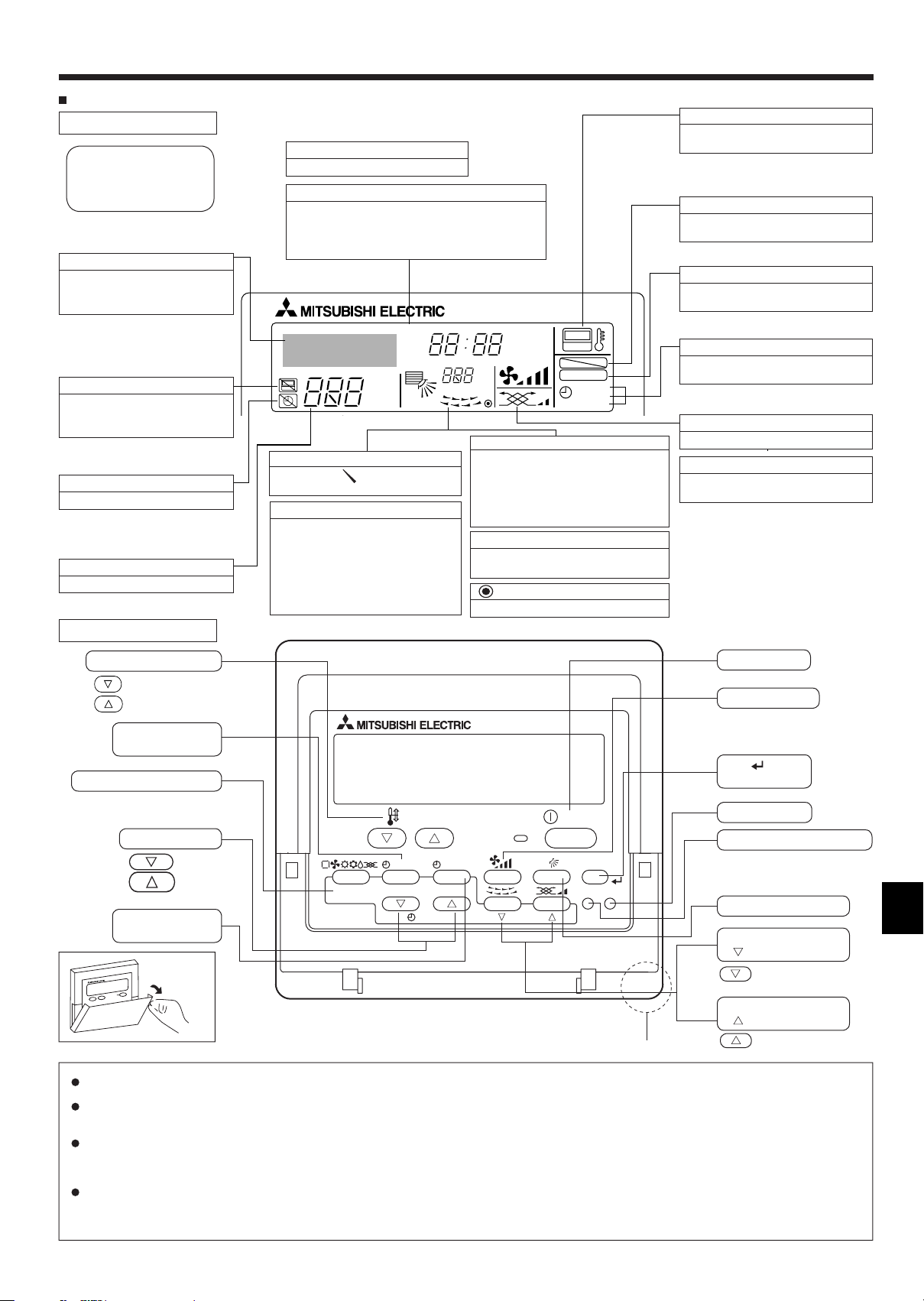
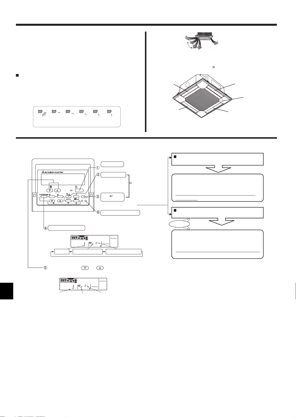
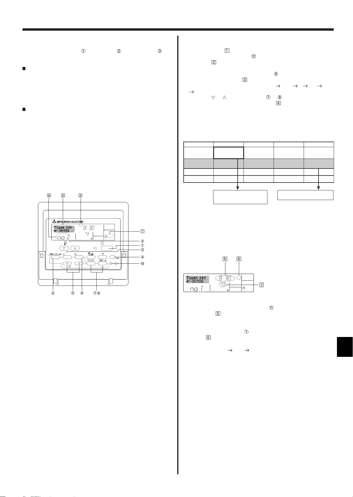
2. Parts Names
Wired Remote-Controller
Display Section
For purposes of this explanation,
all parts of the display are shown.
During actual operation, only the
relevant items will be displayed.
Identifi es the current operation
Shows the operating mode, etc.
* Multi-language display is sup-
ported.
“Centrally Controlled” indicator
Indicates that operation of the
remote controller has been prohibited by a master controller.
“Timer is Off” indicator
Indicates that the timer is off.
Temperature Setting
Shows the target temperature.
Operation Section
Day-of-Week
Shows the current day of the week.
Time/Timer Display
Shows the current time, unless the simple or Auto
Off timer is set.
If the simple or Auto Off timer is set, shows the
time remaining.
TIME SUN MON TUE WED THU FRI SAT
TIMER
AFTER
ERROR CODE
˚F˚C
˚F˚C
ONLY1Hr.
Up/Down Air Direction indicator
The indicator shows the direction
of the airfl ow.
“One Hour Only” indicator
Displayed if the airfl ow is set to Low
and downward during COOL or DRY
mode. (Operation varies according to
model.)
The indicator goes off after one hour
when the airfl ow direction also changes.
Room Temperature display
Shows the room temperature. The room
temperature display range is 8–39°C
46–102 °F
temperature is less than
39 °C, 102 °F or more.
Louver display
Indicates the action of the swing louver.
Does not appear if the louver is stationary.
(Power On indicator)
Indicates that the power is on.
ON
Hr
OFF
AFTER
FUNCTION
FILTER
WEEKLY
SIMPLE
AUTO OFF
. The display fl ashes if the
8 °C, 46 °F or
“Sensor” indication
Displayed when the remote controller
sensor is used.
“Locked” indicator
Indicates that remote controller buttons have been locked.
“Clean The Filter” indicator
Comes on when it is time to clean
the fi lter.
Timer indicators
The indicator comes on if the corresponding timer is set.
Fan Speed indicator
Shows the selected fan speed.
Ventilation indicator
,
Appears when the unit is running in
Ventilation mode.
Set Temperature buttons
Down
Up
Timer Menu button
(Monitor/Set button)
Mode button (Return button)
TEMP.
Set Time buttons
Back
Ahead
Timer On/Off button
(Set Day button)
Opening the
door
Note:
“PLEASE WAIT” message
This message is displayed for approximately 3 minutes when power is supplied to the indoor unit or when the unit is recovering from a power failure.
Operation mode blinking display
BACK DAY
PAR-21MAA
MENU
MONITOR/SET
CLOCK
ON/OFF
OPERATION
ON/OFF
FILTER
CHECK
TEST
CLEAR
Built-in temperature sensor
ON/OFF button
Fan Speed button
Filter button
(<Enter> button)
Test Run button
Check button (Clear button)
Airfl ow Up/Down button
Louver button
Operation button)
(
To return operation
number
Ventilation button
Operation button)
(
To go to next operation
number
When multiple indoor units are connected to a single outdoor unit and an operation mode is selected for one indoor unit that is different from the
current operation mode of another indoor unit, the operation mode display fl ashes. Select the same operation mode of the other indoor unit.
“NOT AVAILABLE” message
This message is displayed if a button is pressed to operate a function that the indoor unit does not have.
When the same remote controller is used to operate multiple indoor units, this message is displayed if the main indoor unit is not equipped with
the selected function.
Room temperature display
The indoor unit temperature sensors or the remote controller temperature sensor can be selected to measure the room temperature. The indoor
unit temperature sensors are the initial setting. When the indoor unit temperature sensors are selected to measure the room temperature, the
room temperature measured at the main indoor unit is displayed on the remote controller that operates multiple indoor units.
3
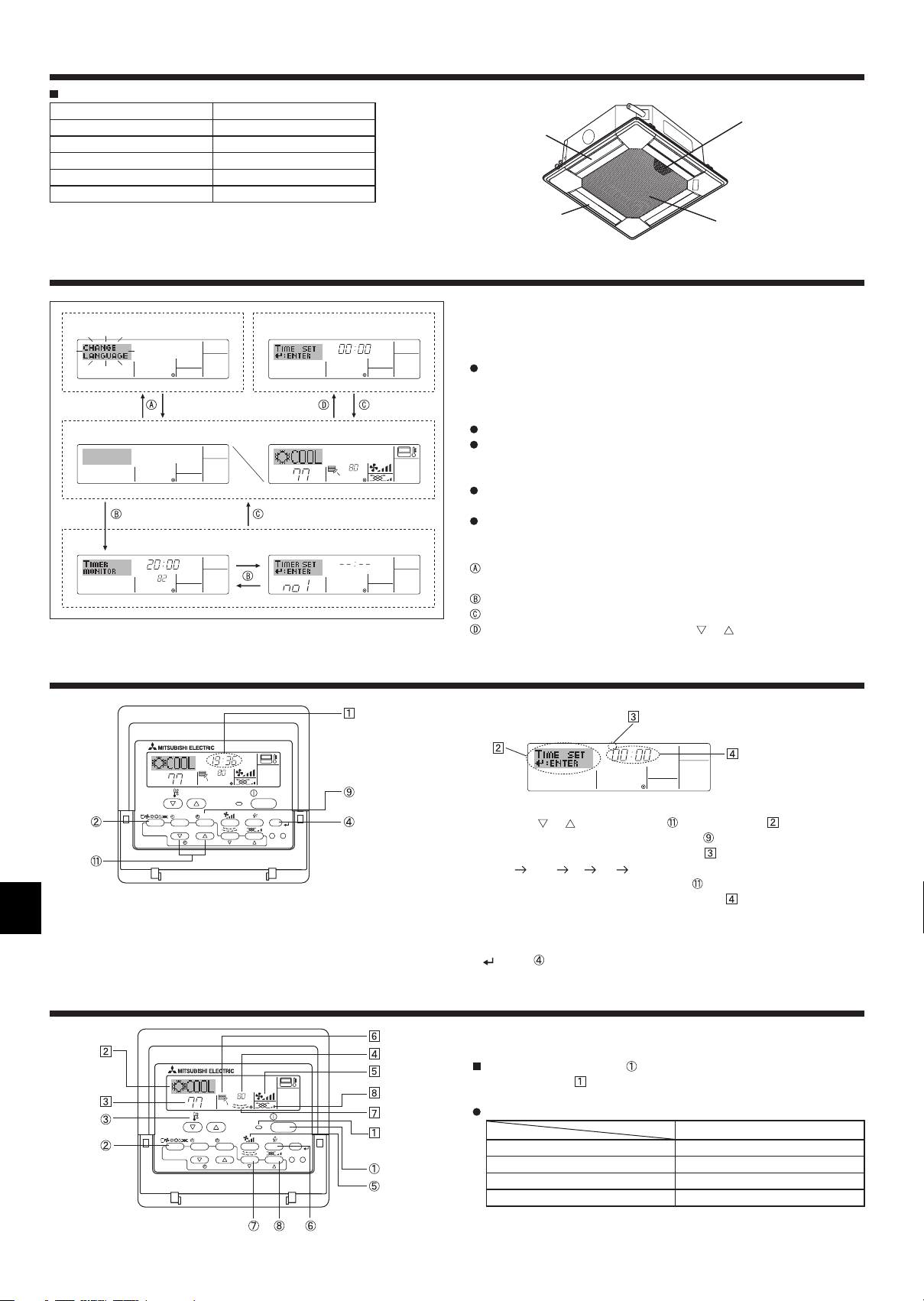
2. Parts Names
Indoor Unit
PLFY-P.NBMU-E
Fan steps 4 steps
Vane Auto with swing
Louver –
Filter Long-life
Filter cleaning indication 2,500 hr
3. Screen Confi guration
Function Selection of remote controller
Standard Control Screens
OFF ON
Timer Monitor Timer Setup
MON
TIMER
OFF
°F°C
WEEKLY
Set Day/Time
°F°C
TIME SUN
°F°C
SUN MON TUE WED THU FRI SAT
WEEKLY
Air outlet
Vane
Filter
Air intake
<Screen Types>
For details on setting the language for the remote controller display, refer
to section 8. Function Selection.
The initial language setting is English.
Function Selection of remote controller:
Set the functions and ranges available to the
remote controller (timer functions, operating
restrictions, etc.)
Set Day/Time: Set the current day of the week or time.
Standard Control Screens:
View and set the air conditioning system’s op-
erating status
Timer Monitor: View the currently set timer (weekly timer, sim-
ple timer, or Auto Off timer)
Timer Setup: Set the operation of any of the timers (weekly
timer, simple timer or Auto Off timer).
<How to change the screen>
: Hold down both the Mode button and the Timer On/Off button for 2
seconds.
: Press the Timer Menu button.
: Press the Mode (Return) button.
: Press either of the Set Time buttons ( or ).
4. Setting the Day of the Week and Time
Day of the week and
time display
°F°C
TEMP.
MENU
BACK DAY
MONITOR/SET
PAR-21MAA
CLOCK
TIME SUN
ON/OFF
°F°C
OPERATION
ON/OFF
FILTER
CHECK
CLEAR
TEST
Note:
The day and time will not appear if clock use has been disabled at Function
Selection of remote controller.
5. Operation
°F°C
°F°C
TEMP.
MENU
MONITOR/SET
BACK DAY
PAR-21MAA
ON/OFF
CLOCK
OPERATION
ON/OFF
FILTER
CHECK
CLEAR
TEST
Day of the week Setting
TIME SUN
Time Setting
1. Press the or Set Time button to show display .
2. Press the Timer On/Off (Set Day) button to set the day.
* Each press advances the day shown at :
Sun Mon ... Fri Sat.
3. Press the appropriate Set Time button as necessary to set the time.
* As you hold the button down, the time (at ) will increment fi rst in
one-minute intervals, then in ten-minute intervals, and then in onehour intervals.
4. After making the appropriate settings at Steps 2 and 3, press the Filter
button to lock in the values.
5.1. Turning ON/OFF
<To Start Operation>
Press the ON/OFF button .
• The ON lamp and the display area come on.
Note:
When the unit is restarted, initial settings are as follows.
Remote Controller settings
Mode Last operation mode
Temperature setting Last set temperature
Fan speed Last set fan speed
Airfl ow up/down Last setting
4
5. Operation
<To Stop Operation>
Press the ON/OFF button again.
• The ON lamp and the display area go dark.
Note:
Even if you press the ON/OFF button immediately after shutting down the operation is progress, the air conditioner will not start for about three minutes.
This is to prevent the internal components from being damaged.
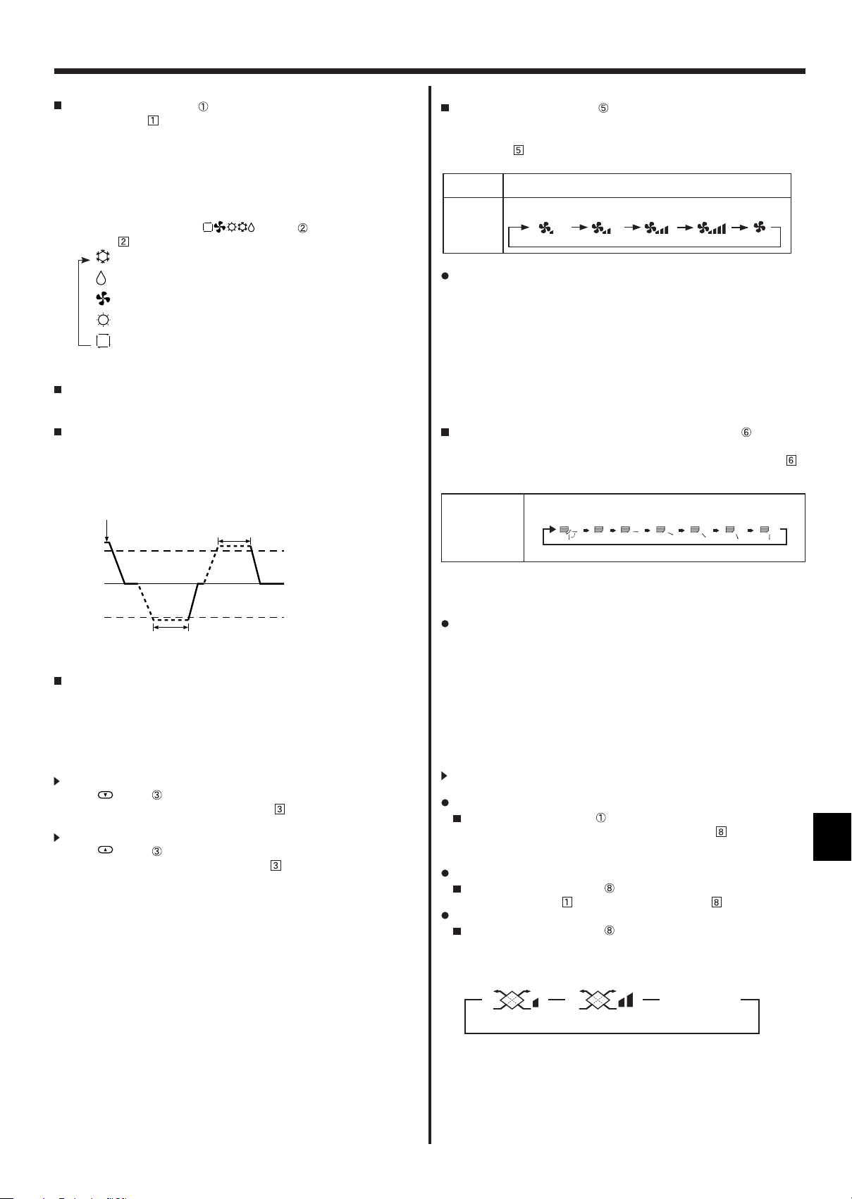
5.2. Mode select
Press the operation mode ( ) button and select the opera-
tion mode .
Cooling mode
Drying mode
Fan mode
Heating mode
Automatic (cooling/heating) mode
Automatic operation
According to a set temperature, cooling operation starts if the room
temperature is too hot and heating operation starts if the room temperature is too cold.
During automatic operation, if the room temperature changes and re-
mains 1.5 °C, 3 °F or more above the set temperature for 3 minutes,
the air conditioner switches to cooling mode. In the same way, if the
room temperature remains 1.5 °C, 3 °F or more below the set temperature for 3 minutes, the air conditioner switches to heating mode.
5.4. Fan speed setting
Press the Fan Speed button as many times as necessary while the
system is running.
• Each press changes the force. The currently selected speed is
shown at
.
• The change sequence and the available settings are as follows.
FAN SPEED Display
4-speed
+
Auto
Note:
In the following cases, the actual fan speed generated by the unit will differ
from the speed shown on the remote controller display.
1. While the display is showing “STAND BY” or “DEFROST”.
2. When the temperature of the heat exchanger is low in the heating mode.
(e.g. immediately after heating operation starts)
3. In HEAT mode, when room temperature is higher than the temperature
setting.
4. When the unit is in DRY mode.
Speed 1 Speed 2 Speed 3 Speed 4 Au to
5.5. Airfl ow direction setting
<To Change the Airfl ow’s Up/Down Direction>
With the unit running, press the Airfl ow Up/Down button as neces-
sary.
•
Each press changes the direction. The current direction is shown at
• The change sequence and the available settings are as follows.
.
Cooling mode
3 minutes (switches from
cooling to heating )
3 minutes (switches from
heating to cooling)
Set temperature +1.5°C, +3°F
Set temperature
Set temperature -1.5°C, -3°F
Because the room temperature is automatically adjusted in order to
maintain a fi xed effective temperature, cooling operation is performed
a few degrees warmer and heating operation is performed a few degrees cooler than the set room temperature once the temperature is
reached (automatic energy-saving operation).
5.3. Temperature setting
To decrease the room temperature:
Press
The selected temperature is displayed .
To increase the room temperature:
Press button to set the desired temperature.
The selected temperature is displayed .
• Available temperature ranges are as follows:
Cooling/Drying: 19 - 30 °C, 67 - 87 °F
Heating: 17 - 28 °C, 63 - 83 °F
Automatic: 19 - 28 °C, 67 - 83 °F
• The display fl ashes either 8 °C - 39 °C, 46 °F - 102 °F to inform you if
the room temperature is lower or higher than the displayed temperature.
button to set the desired temperature.
Display
Swing
Auto 1 2
3
5
4
*Note that during swing operation, the directional indication on the screen
does not change in sync with the directional vanes on the unit.
Note:
In the following cases, the actual air direction will differ from the direction
indicated on the remote controller display.
1. While the display is showing “STAND BY” or “DEFROST”.
2. Immediately after starting heater mode (while the system is waiting for
the mode change to take effect).
3. In heat mode, when room temperature is higher than the temperature
setting.
5.6. Ventillation
For LOSSNAY combination
5.6.1. For Wired Remote-controller
To run the ventilator together with the indoor unit:
Press the ON/OFF button .
• The Vent indication appears on the screen (at ). The ventilator
will now automatically operate whenever the indoor unit is running.
To run the ventilator only when the indoor unit is off:
Press the Ventilation button while the indoor unit is off.
• The On lamp (at ) and the Vent indication (at ) come on.
To change the ventilator force:
Press the Ventilation button as necessary.
• Each press toggles the setting, as shown below.
No display
(Stop)
(Low) (High)
(OFF)
Note:
With some model confi gurations, the fan on the indoor unit may come on
even when you set the ventilator to run independently.
5
5. Operation
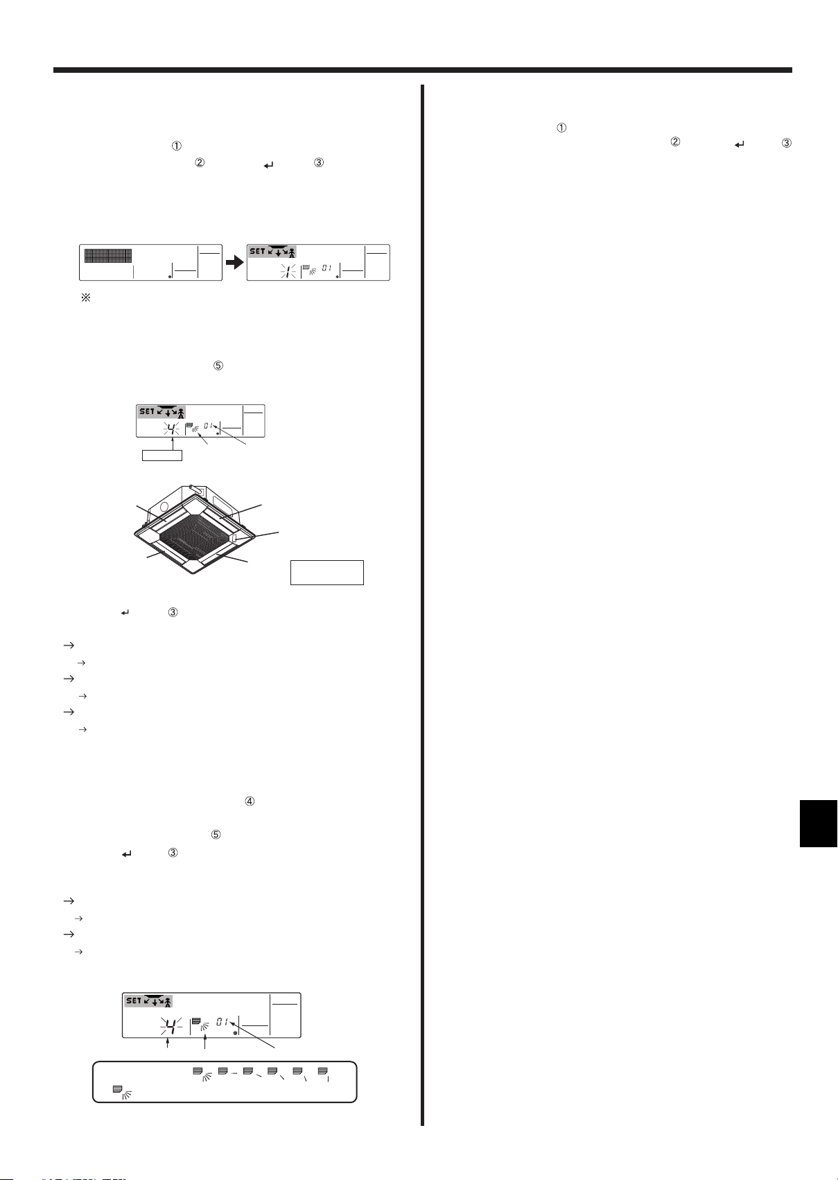
< How to set the fixed up/down air direction (Only for
wired remote controller) >
• For PLFY-BM, only the particular outlet can be fi xed to certain direction
with the procedures below. Once fi xed, only the set outlet is fi xed every
time air conditioner is turned on. (Other outlets follow UP/DOWN air
direction setting of remote controller.)
Explanation of word
• "Address No. of indoor unit" is the number given to each air conditioner.
• "Outlet No." is the number given to each outlet of air conditioner.
(Refer to the right.)
• "Up/Down air direction" is the direction (angle) to fi x.
Reset 1
horizontal
2345
Operation buttons (During the fi xed airfl ow direction mode)
ON/OFF button
Resets the fixed airflow direction mode.
TEMP.
MENU
ON/OFF
MONITOR/SET
BACK DAY
PAR-21MAA
CLOCK
Mode button (Return button)
Moves between the selected(blinking)
parts.
Outlet No.
OPERATION
Up/Down air direction
ON/OFF
FILTER
CHECK
CLEAR
Fan Speed button
TEST
Filter button
(<Enter> button)
Sends the information on
remote controller display.
Check button (Clear button)
·Refer to the next page for details.
Address No. of indoor unit
Press for 2
seconds to
change / cancel
"Fixed airflow
direction mode".
Horizontal airflow
Remote controller setting
The airflow direction of
this outlet is controlled by
the airflow direction setting of
remote contoller.
Outlet No.3
Outlet No.2
Note: "0" indicates all outlets.
Pressing the button with either Address No. of
indoor unit or outlet No. blinking, ...
Only the air conditioner with the No. on remote
controller and its outlet are set to the setting 5.
(Other outlets are closed.)
It is used to identify the air conditioner and
outlet to set.
Pressing the button with
Up/Down air direction indicater blinking
Attention
Only the air conditioner with the No. on Remote controller
and its outlet are fixed at "Up/Down air direction"
blinking.
This is used only to decide direction conclusively.
Attention: Be careful not to set wrong air conditioner.
Downward
Fixing
The airflow direction of
this outlet is fixed
in particular direction.
When it is cold because of direct airflow,
the airflow direction can be fixed
horizontally to avoid direct airflow.
Outlet No.4
MITSUBISHI
ELECTRIC
label
Outlet No.1
5 steps or
cancel
Down
Up
Address No. of indoor unit
"01-50"
Set temperature buttons
Changes the selection(No.).
Outlet No.
"1-4"or "0"
Up/Down air direction
6
5. Operation
< Process for setting >
[1] To turn off air conditioner and change the remote
controller to "Fixed airfl ow direction mode"
1.Press ON/OFF button to turn off the air conditioner.
2.Press Fan Speed button and Filter button for more than 2
seconds simultaneously and it becomes the fixed airflow direction
mode after a while.
"Fixed airflow direction mode" display
Air blows downward after it becomes
"fixed airflow direction mode"
[2] To select and identify the outlet to set
1.Press Set Temperature button to change number with the outlet No.
blinking. Select outlet No. to set.
[4] To cancel "Fixed airfl ow direction mode"
1.Press ON/OFF button to cancel "Fixed airfl ow direction mode".It is
also canceled by pressing Fan Speed button
and Filter button
for more than 2 seconds simultaneously.
2.Do not operate remote controller for 30 seconds after the "Fixed
airflowdirection mode" is canceled. It does not accept even if it is
operated.
Outlet No.3
2.Press Filter
Outlet No.
Outlet No.2
button
Up/Down air direction
to send the information on remote controller.
Address No. of indoor unit
Outlet No.4
MITSUBISHI
ELECTRIC
Outlet No.1
label
Note: "0" indicates
all outlets.
3. Wait for 15 seconds . How does the air conditioner run?
Only the air from the selected outlet blows downward.
Go to step[3].
Air from the wrong outlet blows downward.
Repeat 1 and set again.
All outlets are closed.
The number of the air conditioner (Address No. of indoor unit) is
wrong. Refer to How to fi nd air conditioner No..
[3] To fi x air direction
1.Press Mode button (Return button)
indicater.
2.Press Set Temperature button until the direction to set is chosen.
3.Press Filter
button
to send the information on remote controller to
air conditioner.
4.Wait for 15 seconds . How does the air conditioner run?
Airfl ow direction is set in the selected direction.
The fi xed setting is completed (Go to step [4].)
Airfl ow direction is set in the wrong direction.
Repeat 2. and set again.
to blink Up/Down air direction
Outlet No.
Air direction changes
Up/Down air direction
This indicates NO FIXED SETTING(canceled)
Address No. of indoor unit
7
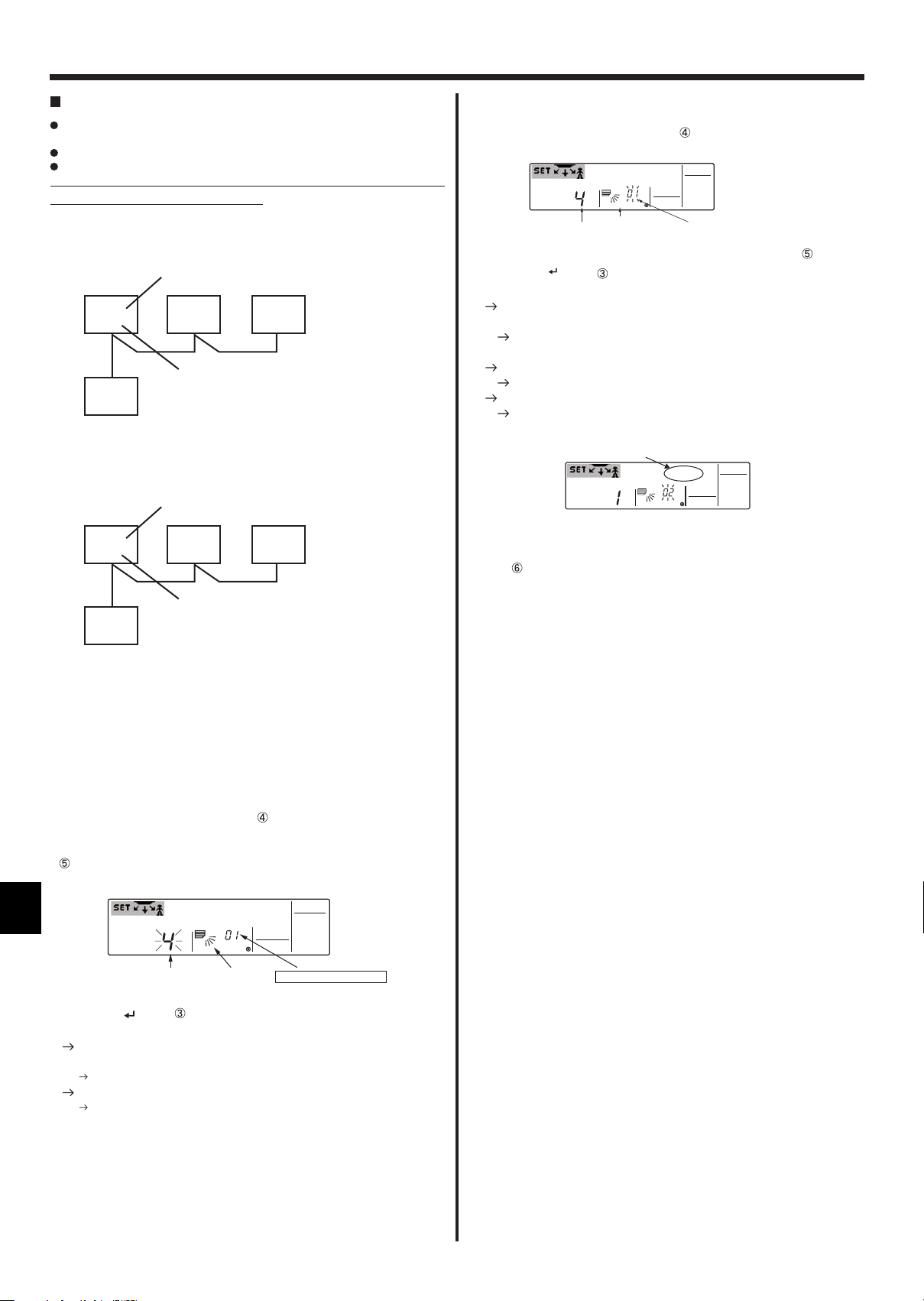
5. Operation
How to fi nd air conditioner No.
Each air conditioner has its own Address No. of indoor unit (Example
below).
Address No. of indoor unit can be set ranging from "01" to "50".
To fi nd air conditioner No. to set, refer to the procedures below.
Air conditioner No. is found by its airfl ow direction with Address No. of
indoor unit changed one after the other.
Example) Structure of the system
Indoor unit
(00)
01
When the Switch setting of the address is "00",
address No. of indoor unit is given automatically
Indoor unit
(01)
01
Switch setting of the address
(00)
(00)
02
Address No. of indoor unit
MA remote controller
Switch setting of the address
(02)
(03)
02
Address No. of indoor unit
03
03
[2] To check by changing Address No. of indoor unit one after the
other (Maximum unit No. is 50)
1.Press Mode button (Return button) and Address No. of indoor unit
blinks.
Outlet No.
Up/Down
air direction
Addres No. of indoor unit
Adjust to the next address No.with Set Temperature button .
2. Press Filter button to send the information on remote controller.
3. Wait for 15 seconds after sending. How does the air conditioner run?
Only air from the outlet which No. displayed on remote controller blows
downward.
No. displayed in remote controller is air conditioner No. (Checking
completed)
All outlets are closed.
Repeat [1] and continue this procedure.
"Err" is displayed on remote controller.
This groupe does not have this address No. of indoor unit.(Go
back to [1] and continue .)
Err
To clear fi xed setting
To clear all fi xed setting(reset to factory default), press check button(clear
botton) for more than 3 seconds in fi xed airfl ow direction mode.
Display of remote controller blinks and the set information is cleared.
Note:
This operation clears the fixed setting information of all air
conditioner connected to the remote controller.
MA remote controller
When the Switch setting of the address is not "00", switch
setting of the address is also address No. of indoor unit.
<Process to fi nd air conditioner No.>
[1] To check Address No. of indoor unit
1.Press Mode button (Return button) and Address No. of indoor unit
blinks.
Adjust address No. of indoor unit to "01" with Set Temperature button
.
Outlet No.
2.Press Filter button to send the information on remote controller.
3. Wait for 15 seconds . How does the air conditioner run?
Only air from the outlet which No. displayed on remote controller
blows downward.
Address No.01 of indoor unit
All outlets are closed.
Go to step [2].
Up/Down
air direction
Address No. of indoor unit
is the air conditioner No..
8
6. Timer
6.1. For Wired Remote-controller
You can use Function Selection of remote controller to select which of
three types of timer to use: Weekly timer, Simple timer, or Auto
Off timer.
6.1.1. Weekly Timer
The weekly timer can be used to set up to eight operations for each
day of the week.
• Each operation may consist of any of the following: ON/OFF time
together with a temperature setting, or ON/OFF time only, or temperature setting only.
• When the current time reaches a time set at this timer, the air conditioner carries out the action set by the timer.
Time setting resolution for this timer is one minute.
Note:
*1. Weekly Timer/Simple Timer/Auto Off Timer cannot be used at the same
time.
*2. The weekly timer will not operate when any of the following conditions is
in effect.
The timer feature is off; the system is in an malfunction state; a test run
is in progress; the remote controller is undergoing self-check or remote
controller check; the user is in the process of setting a function; the user
is in the process of setting the timer; the user is in the process of setting
the current day of the week or time; the system is under central control.
(Specifi cally, the system will not carry out operations (unit on, unit off, or
temperature setting) that are prohibited during these conditions.)
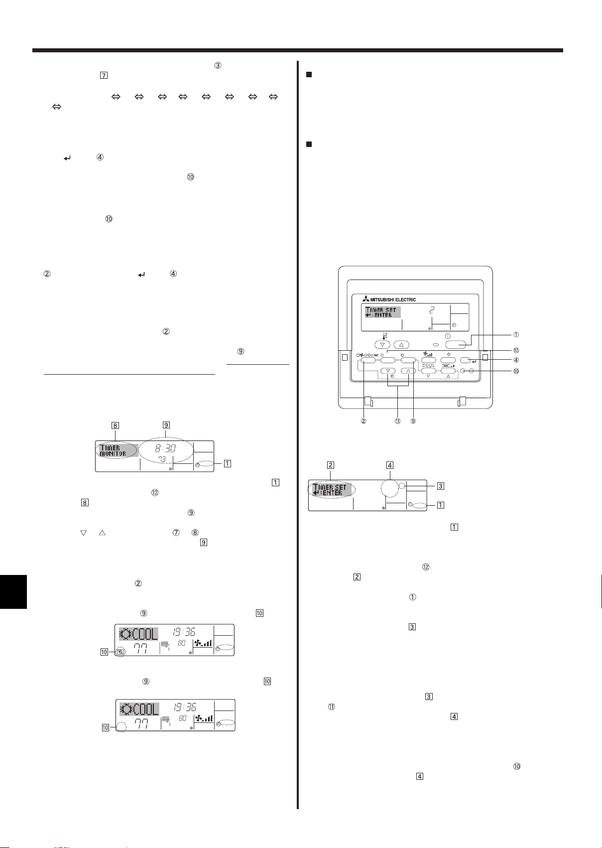
Operation No.
Day Setting
<How to Set the Weekly Timer>
1. Be sure that you are at a standard control screen, and that the weekly timer indicator
is shown in the display.
2. Press the Timer Menu button , so that the “Set Up” appears on the
screen (at
). (Note that each press of the button toggles the display
between “Set Up” and “Monitor”.)
3. Press the Timer On/Off (Set Day) button to set the day. Each press
advances the display at to the next setting, in the following sequence: “Sun Mon Tues Wed Thurs Fri Sat” “Sun” ... “Fri” “Sat”
“Sun Mon Tues Wed Thurs Fri Sat”...
4. Press the or Operation button ( or ) as necessary to select
the appropriate operation number (1 to 8) .
* Your inputs at Steps 3 and 4 will select one of the cells from the
matrix illustrated below.
(The remote-controller display at left shows how the display would
appear when setting Operation 1 for Sunday to the values indicated below.)
Setup Matrix
Op No. Sunday Monday … Saturday
No. 1
No. 2 • 10:00
…
No. 8
• 8:30
• ON
• 73 °F
• OFF
<Operation 1 settings for Sunday>
Start the air conditioner at 8:30, with
the temperature set to 73 °F.
• 10:00
• OFF
• 10:00
• OFF
<Operation 2 settings for every day>
Turn off the air conditioner at 10:00.
• 10:00
• OFF
TEMP.
MENU
MONITOR/SET
BACK DAY
PAR-21MAA
CLOCK
SUN
ON/OFF
°F°C
OPERATION
ON
WEEKLY
ON/OFF
FILTER
CHECK
CLEAR
TEST
Note:
By setting the day to “Sun Mon Tues Wed Thurs Fri Sat”, you can set the same
operation to be carried out at the same time every day.
(Example: Operation 2 above, which is the same for all days of the week
<Setting the Weekly Timer>
Shows the time setting
SUN
°F°C
Shows the temperature setting
* Does not appear if temperature is not set.
ON
WEEKLY
Shows the selected operation (ON or OFF)
*Does not appear if operation is not set.
5.Press the appropriate Set Time button as necessary to set the de-
sired time (at ).
* As you hold the button down, the time fi rst increments in one-minute
intervals, then in ten-minute intervals, and then in one-hour intervals.
6.Press the ON/OFF button
OFF), at
.
to select the desired operation (ON or
* Each press changes the next setting, in the following sequence: No
display (no setting) “ON” “OFF”
9
6. Timer
7. Press the appropriate Set Temperature button to set the desired
temperature (at ).
* Each press changes the setting, in the following sequence: No dis-
play (no setting) 75 77 ... 84 87 53 ... 73
No display.
(Available range: The range for the setting is 12 °C, 53 °F to 30 °C,
87 °F. The actual range over which the temperature can be controlled, however, will vary according to the type of the connected unit.)
8. After making the appropriate settings at Steps 5, 6 and 7, press the
Filter button to lock in the values.
To clear the currently set values for the selected operation, press and
quickly release the Check (Clear) button once.
* The displayed time setting will change to “—:—”, and the On/Off
and temperature settings will all disappear.
(To clear all weekly timer settings at once, hold down the Check
(Clear) button for two seconds or more. The display will begin
blinking, indicating that all settings have been cleared.)
Note:
Your new entries will be cancelled if you press the Mode (Return) button
before pressing the Filter button .
If you have set two or more different operations for exactly the same time,
only the operation with the highest Operation No. will be carried out.
9. Repeat Steps 3 to 8 as necessary to fi ll as many of the available cells
as you wish.
10. Press the mode (Return) button to return to the standard control
screen and complete the setting procedure.
11. To activate the timer, press the Timer On/Off button , so that the
“Timer Off” indication disappears from the screen. Be sure that the
“Timer Off” indication is no longer displayed.
* If there are no timer settings, the “Timer Off” indication will blink on
the screen.
6.1.2. Simple Timer
You can set the simple timer in any of three ways.
• Start time only:
The air conditioner starts when the set time has elapsed.
• Stop time only:
The air conditioner stops when the set time has elapsed.
• Start & stop times:
The air conditioner starts and stops at the respective elapsed times.
The simple timer (start and stop) can be set only once within a 72-hour
period.
The time setting is made in hour increments.
Note:
*1. Weekly Timer/Simple Timer/Auto Off Timer cannot be used at the same
time.
*2. The simple timer will not operate when any of the following conditions is
in effect.
The timer is off; the system is in malfunction state; a test run is in
progress; the remote controller is undergoing self-check or remote controller check; the user is in the process of selecting a function; the user
is in the process of setting the timer; the system is under central control.
(Under these conditions, On/Off operation is prohibited.)
ONHr
AFTER
SIMPLE
TEMP.
MENU
BACK DAY
MONITOR/SET
PAR-21MAA
ON/OFF
CLOCK
OPERATION
ON/OFF
FILTER
CHECK
CLEAR
TEST
<How to View the Weekly Timer Settings>
Timer Settings
SUN
TIMER
1.
Be sure that the weekly timer indicator is visible on the screen (at ).
ON
OFF
°F°C
WEEKLY
2. Press the Timer Menu button so that “Monitor” is indicated on the
screen (at
).
3. Press the Timer On/Off (Set Day) button as necessary to select the
day you wish to view.
4. Press the or Operation button ( or ) as necessary to change
the timer operation shown on the display (at ).
* Each press will advance to the next timer operation, in order of time
setting.
5. To close the monitor and return to the standard control screen, press
the Mode (Return) button .
<To Turn Off the Weekly Timer>
Press the Timer On/Off button so that “Timer Off” appears at .
TIME SUN
°F°C
°F°C
WEEKLY
<To Turn On the Weekly Timer>
Press the Timer On/Off button so that “Timer Off” appears (at ) and
goes dark.
TIME SUN
°F°C
°F°C
WEEKLY
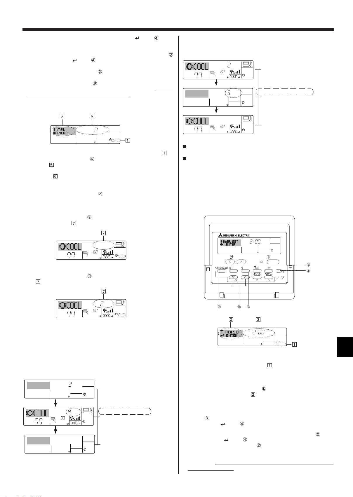
<How to Set the Simple Timer >
Timer Setting
ONHr
AFTER
SIMPLE
1. Be sure that you are at a standard control screen, and that the simple
timer indicator is visible in the display (at ).
When something other than the Simple Timer is displayed, set it to
SIMPLE TIMER using the function selection of remote controller (see
8.[4]–3 (3)) timer function setting.
2. Press the Timer Menu button , so that the “Set Up” appears on the
screen (at ). (Note that each press of the button toggles the display
between “Set Up” and “Monitor”.)
3. Press the ON/OFF button to display the current ON or OFF simple
timer setting. Press the button once to display the time remaining to
ON, and then again to display the time remaining to OFF. (The ON/
OFF indication appears at ).
• “ON” timer:
The air conditioner will start operation when the specifi ed number of
hours has elapsed.
• “OFF” timer:
The air conditioner will stop operation when the specifi ed number of
hours has elapsed.
4. With “ON” or “OFF” showing at : Press the appropriate Set Time button as necessary to set the hours to ON (if “ON” is displayed) or the
hours to OFF (if “OFF” is displayed) at .
• Available Range: 1 to 72 hours
5. To set both the ON and OFF times, repeat Steps 3 and 4.
* Note that ON and OFF times cannot be set to the same value.
6. To clear the current ON or OFF setting: Display the ON or OFF setting
(see step 3) and then press the Check (Clear) button so that the
time setting clears to “—” at . (If you want to use only an ON setting
or only an OFF setting, be sure that the setting you do not wish to use
is shown as “—”.)
Action (On or Off)
* “— —” is displayed if there is no
setting.
10
6. Timer
7. After completing steps 3 to 6 above, press the Filter button to lock
in the value.
Note:
Your new settings will be cancelled if you press the Mode (Return) button
before pressing the Filter button .
8. Press the Mode (Return) button to return to the standard control
screen.
9. Press the Timer On/Off button to start the timer countdown. When
the timer is running, the timer value is visible on the display. Be sure
that the timer value is visible and appropriate.
<Viewing the Current Simple Timer Settings>
Timer Setting
TIMER ON
OFFHrAFTER
SIMPLE
1. Be sure that the simple timer indicator is visible on the screen (at ).
2. Press the Timer Menu button , so that the “Monitor” appears on the
screen (at ).
• If the ON or OFF simple timer is running, the current timer value will
appear at .
• If ON and OFF values have both been set, the two values appear
alternately.
3. Press the Mode (Return) button to close the monitor display and
return to the standard control screen.
<To Turn Off the Simple Timer...>
Press the Timer On/Off button so that the timer setting no longer appears on the screen (at ).
Example 2:
Start the timer : OFF time is set earlier than ON time.
ON Setting : 5 hours
OFF Setting : 2 hours
OFFHrAFTER
°F°C
°F°C
°F°C
ONHr
AFTER
°F°C
At Timer Start
Display shows the timer’s OFF setting (hours
SIMPLE
remaining to OFF).
At 2 hours after timer start
Display changes to show the timer’s ON setting (hours remaining to ON).
SIMPLE
The time displayed is ON setting (5 hours) –
OFF setting (2 hours) = 3 hours.
At 5 hours after timer start
The air conditioner comes on and will continue
SIMPLE
to run until it is turned off.
6.1.3. Auto Off Timer
This timer begins countdown when the air conditioner starts and shuts
the air conditioner off when the set time has elapsed.
Available settings run from 30 minutes to 4 hours in 30-minute inter-
vals.
Note:
*1. Weekly Timer/Simple Timer/Auto Off Timer cannot be used at the same
time.
*2. The Auto Off timer will not operate when any of the following conditions
is in effect.
The timer is off; the system is in malfunction state; a test run is in
progress; the remote controller is undergoing self-check or remote controller check; the user is in the process of selecting a function; the user is
in the process of setting the timer; the system is under central control.
°F°C
°F°C
SIMPLE
<To Turn On the Simple Timer...>
Press the Timer On/Off button
so that the timer setting becomes vis-
ible at .
ONHr
AFTER
°F°C
°F°C
SIMPLE
Examples
If ON and OFF times have both been set at the simple timer, operation
and display are as indicated below.
Example 1:
Start the timer : ON time is set earlier than OFF time.
ON Setting : 3 hours
OFF Setting : 7 hours
ONHr
°F°C
AFTER
OFFHrAFTER
°F°C
At Timer Start
Display shows the timer’s ON setting (hours
SIMPLE
remaining to ON).
At 3 hours after timer start
Display changes to show the timer’s OFF set-
SIMPLE
ting (hours remaining to OFF).
The time displayed is OFF setting (7 hours) –
ON setting (3 hours) = 4 hours.
At 7 hours after timer start
The air conditioner goes off, and will remain
SIMPLE
off until it is restarted.
AFTER OFF
OPERATION
AUTO OFF
ON/OFF
FILTER
CHECK
CLEAR
TEST
TEMP.
MENU
MONITOR/SET
BACK DAY
PAR-21MAA
ON/OFF
CLOCK
(Under these conditions, On/Off operation is prohibited.)
Timer Setting
AFTER OFF
AUTO OFF
<How to Set the Auto Off Timer>
1.Be sure that you are at a standard control screen, and that the Auto Off
timer indicator is visible in the display (at ).
When something other than the Auto Off Timer is displayed, set it to
AUTO OFF TIMER using the function selection of remote controller (see
8.[4]–3 (3)) timer function setting.
2. Hold down the Timer Menu button
Up” appears on the screen (at
for 3 seconds so that the “Set
).
(Note that each press of the button toggles the display between “Set
Up” and “Monitor”.)
3. Press the appropriate Set Time button A as necessary to set the OFF
time (at ).
4. Press the Filter button to lock in the setting.
Note:
Your entry will be cancelled if you press the Mode (Return) button
pressing the Filter
button .
before
5. Press the Mode (Return) button to complete the setting procedure
and return to the standard control screen.
6. If the air conditioner is already running, the timer starts countdown
immediately. Be sure to check that the timer setting appears cor-
rectly on the display.
11
6. Timer
<Checking the Current Auto Off Timer Setting>
Timer Setting
TIMER
AFTER
OFF
AUTO OFF
1.Be sure that the “Auto Off” is visible on the screen (at ).
2. Hold down the Timer Menu button for 3 seconds so that “Monitor” is
indicated on the screen (at ).
• The timer remaining to shutdown appears at .
3. To close the monitor and return to the standard control screen, press
the Mode (Return) button .
<To Turn Off the Auto Off Timer...>
Hold down the Timer On/Off button for 3 seconds so that “Timer
Off” appears (at ) and the timer value (at ) disappears.
°F°C
°F°C
AUTO OFF
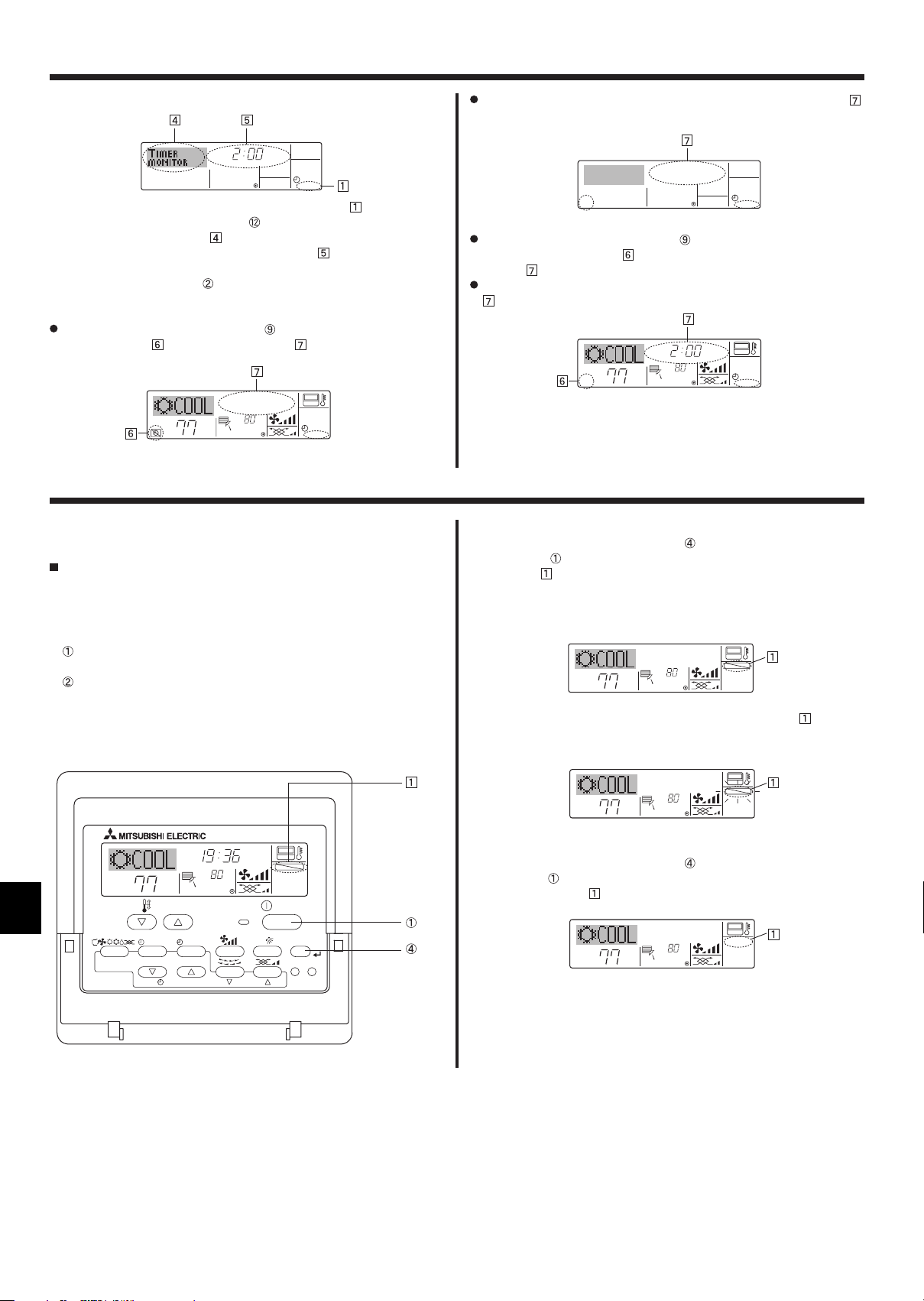
7. Other Functions
7.1. Locking the Remote Controller Buttons (Operation
function limit controller)
If you wish, you can lock the remote controller buttons. You can use the
Function Selection of remote controller to select which type of lock to
use. (For information about selecting the lock type, see section 8, item [4]
–2 (1)).
Specifi cally, you can use either of the following two lock types.
Lock All Buttons:
Locks all of the buttons on the remote controller.
Lock All Except ON/OFF:
Locks all buttons other than the ON/OFF button.
Note:
The “Locked” indicator appears on the screen to indicate that buttons are
currently locked.
Alternatively, turn off the air conditioner itself. The timer value (at )
will disappear from the screen.
AUTO OFF
<To Turn On the Auto Off Timer...>
Hold down the Timer On/Off button for 3 seconds. The “Timer Off”
indication disappears (at
play (at
).
), and the timer setting comes on the dis-
Alternatively, turn on the air conditioner. The timer value will appear at
.
AFTER OFF
°F°C
°F°C
AUTO OFF
<How to Lock the Buttons>
1. While holding down the Filter button , press and hold down the ON/
OFF button for 2 seconds. The “Locked” indication appears on the
screen (at ), indicating that the lock is now engaged.
* If locking has been disabled in Function Selection of remote control-
ler, the screen will display the “Not Available” message when you
press the buttons as described above.
°F°C
°F°C
FUNCTION
• If you press a locked button, the “Locked” indication (at ) will blink
on the display.
°F°C
TEMP.
MENU
MONITOR/SET
BACK DAY
PAR-21MAA
CLOCK
TIME SUN
ON/OFF
°F°C
OPERATION
FUNCTION
ON/OFF
FILTER
CHECK
CLEAR
TEST
Locked Indicator
°F°C
°F°C
FUNCTION
<How to Unlock the Buttons>
1. While holding down the Filter button , press and hold down the ON/
OFF button
for 2 seconds so that the “Locked” indication disappears
from the screen (at ).
°F°C
°F°C
12
7. Other Functions
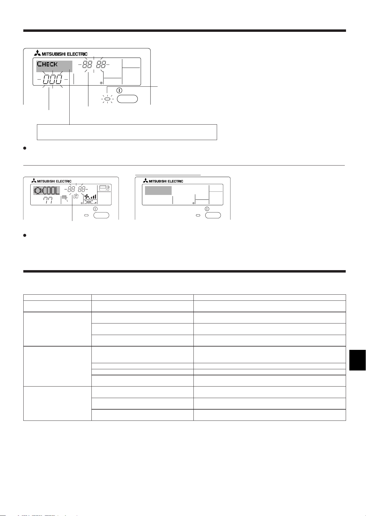
7.2. Error Codes indication
ERROR CODE
ON/OFF
Unit No.
If you have entered contact number to be called in the event of a problem, the screen displays this number.
(You can set this up under Function Selection of remote controller. For information, refer to section 8.)
Error Code
ON lamp
(Blinking)
If the ON lamp and error code are both fl ashing: This means that the air conditioner is out of order and operation has been stopped (and cannot
resume). Take note of the indicated unit number and error code, then switch off the power to the air conditioner and call your dealer or servicer.
When the Check button is pressed:
CALL:XXXX
XXX:XXX
ON/OFF
°F°C
ERROR CODE
°F°C
Error Code
ON/OFF
If only the error code is fl ashing (while the ON lamp remains lit): Operation is continuing, but there may be a problem with the system. In this case,
you should note down the error code and then call your dealer or servicer for advice.
* If you have entered contact number to be called in the event of a problem, push the Check button to display it on the screen. (You can set this up un-
der Function Selection of remote controller. For information, refer to section 8.)
8. Function Selection
Function selection of remote controller
The setting of the following remote controller functions can be changed using the remote controller function selection mode. Change the setting when
needed.
1. Change Language
(“CHANGE LANGUAGE”)
2. Function limit
(“FUNCTION SELECTION”)
3. Mode selection
(“MODE SELECTION”)
4. Display change
(“DISP MODE SETTING”)
Item 1 Item 2 Item 3 (Setting content)
Language setting to display • Display in multiple languages is possible
(1) Operation function limit setting (operation lock)
(“LOCKING FUNCTION”)
(2) Use of automatic mode setting (“SELECT AUTO
MODE”)
(3) Temperature range limit setting (“LIMIT TEMP
FUNCTION”)
(1) Remote controller main/sub setting (“CONTROL-
LER MAIN/SUB”)
(2) Use of clock setting (“CLOCK”) • Setting the use or non-use of clock function
(3) Timer function setting (“WEEKLY TIMER”) • Setting the timer type
(4) Contact number setting for error situation
(“CALL.”)
(1) Temperature display °C/°F setting (“TEMP
MODE °C/°F”)
(2) Room air temperature display setting (“ROOM
TEMP DISP SELECT”)
(3) Automatic cooling/heating display setting (“AUTO
MODE DISP C/H”)
• Setting the range of operation limit (operation lock)
• Setting the use or non-use of “automatic” operation mode
• Setting the temperature adjustable range (maximum, minimum)
• Selecting main or sub remote controller
* When two remote controllers are connected to one group, one controller
must be set to sub.
• Contact number display in case of error
• Setting the telephone number
• Setting the temperature unit (°C or °F) to display
• Setting the use or non-use of the display of indoor (suction).air temperature.
• Setting the use or non-use of the display of “Cooling” or “Heating” display
during operation with automatic mode
13
8. Function Selection
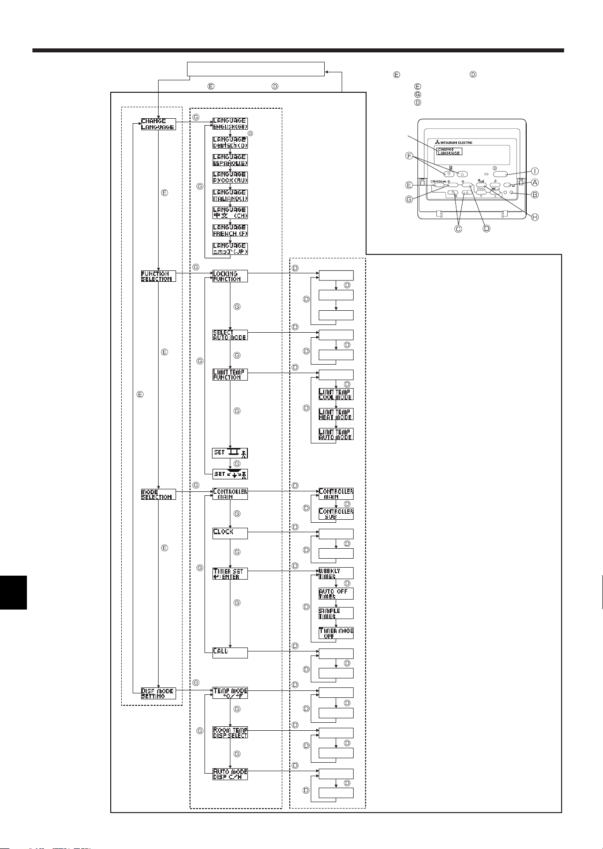
[Function selection fl owchart]
Setting language (English)
Change
Language
Function
selection
Normal display
(Display when the air conditioner is not running)
Hold down the button and press the button for 2 seconds.
Remote controller function selection mode
Item 2Item 1
English
Germany
Spanish
Russian
Italy
Chinese
French
Japanese
Item 3
OFF
no1
no2
ON
OFF
OFF
Hold down the button and press the button for 2 seconds.
Press the operation mode button.
Press the TIMER MENU button.
Press the TIMER ON/OFF button.
Dot display
TEMP.
MENU
MONITOR/SET
BACK DAY
PAR-21MAA
ON/OFF
CLOCK
OPERATION
ON/OFF
CHECK
CLEAR
FILTER
TEST
Operation lock setting is not used.
(Initial setting value)
Operation lock setting is except On/Off button.
Operation lock setting is All buttons.
The automatic mode is displayed when the operation
mode is selected. (Initial setting value)
The automatic mode is not displayed when the operation mode
is selected.
The temperature range limit is not active. (Initial setting value)
Mode
selection
ON
OFF
OFF
CALL-
The temperature range can be changed on cooling/dry mode.
The temperature range can be changed on heating mode.
The temperature range can be changed on automatic mode.
Automatic fi lter elevation panel up/down operation mode
Not necessary to set this mode. Refer to OPERATION MAUAL of
Optional Parts (Panel) for details on operation.
Fixed airfl ow direction mode
Not necessary to set this mode. Refer to OPERATION MAUAL of
indoor unit for details on operation.
The remote controller will be the main controller. (Initial setting value)
The remote controller will be the sub controller.
The clock function can be used. (Initial setting value)
The clock function can not be used.
Weekly timer can be used. (Initial setting value)
Auto off timer can be used.
Simple timer can be used.
Timer mode can not be used.
The set contact numbers are not displayed in case of error.
(Initial setting value)
The set contact numbers are displayed in case of error.
14
Display
mode setting
˚C
˚F
ON
OFF
ON
The temperature unit °C is used. (Initial setting value)
The temperature unit °F is used.
Room air temperature is displayed. (Initial setting value)
Room air temperature is not displayed.
One of “Automatic cooling” and “Automatic heating” is displayed
under the automatic mode is running. (Initial setting value)
OFF
Only “Automatic” is displayed under the automatic mode.
8. Function Selection
[Detailed setting]
[4]–1. CHANGE LANGUAGE setting
The language that appears on the dot display can be selected.
• Press the [ MENU] button to change the language.
English (GB), German (D), Spanish (E), Russian (RU),
Italian (I), Chinese (CH), French (F), Japanese (JP)
Refer to the dot display table.
[4]–2. Function limit
(1) Operation function limit setting (operation lock)
• To switch the setting, press the [ ON/OFF] button .
no1 : Operation lock setting is made on all buttons other than
the [ ON/OFF] button.
no2 : Operation lock setting is made on all buttons.
OFF (Initial setting value): Operation lock setting is not made.
* To make the operation lock setting valid on the normal screen, it
is necessary to press buttons (Press and hold down the [FILTER]
and [ ON/OFF] buttons at the same time for two seconds.) on
the normal screen after the above setting is made.
(2) Use of automatic mode setting
When the remote controller is connected to the unit that has auto-
matic operation mode, the following settings can be made.
• To switch the setting, press the [ ON/OFF] button .
ON (Initial setting value):
The automatic mode is displayed when the operation mode is
selected.
OFF:
The automatic mode is not displayed when the operation
mode is selected.
(3) Temperature range limit setting
After this setting is made, the temperature can be changed within
the set range.
• To switch the setting, press the [ ON/OFF] button .
LIMIT TEMP COOL MODE:
The temperature range can be changed on cooling/dry mode.
LIMIT TEMP HEAT MODE:
The temperature range can be changed on heating mode.
LIMIT TEMP AUTO MODE:
The temperature range can be changed on automatic mode.
OFF (initial setting): The temperature range limit is not active.
* When the setting other than OFF is made, the temperature range
limit setting on cooling, heating and automatic mode is made at
the same time. However, the range cannot be limited when the
set temperature range has not changed.
• To increase or decrease the temperature, press the [ TEMP. ( )
or ( )] button .
• To switch the upper limit setting and the lower limit setting, press
the [ ] button . The selected setting will fl ash and the temperature can be set.
• Settable range
Cooling/Dry mode:
Lower limit: 19 °C – 30 °C, 67 °F – 87 °F
Upper limit: 30 °C – 19 °C, 87 °F – 67 °F
Heating mode:
Lower limit: 17 °C – 28 °C, 63 °F – 83 °F
Upper limit: 28 °C – 17 °C, 83 °F – 63 °F
Automatic mode:
Lower limit: 19 °C – 28 °C, 67 °F – 83 °F
Upper limit: 28 °C – 19 °C, 83 °F – 67 °F
[4]–3. Mode selection setting
(1) Remote controller main/sub setting
• To switch the setting, press the [ ON/OFF] button .
Main: The controller will be the main controller.
Sub: The controller will be the sub controller.
(2) Use of clock setting
• To switch the setting, press the [ ON/OFF] button .
ON: The clock function can be used.
OFF: The clock function cannot be used.
(3) Timer function setting
• To switch the setting, press the [
one of the following.).
WEEKLY TIMER (initial setting value):
The weekly timer can be used.
AUTO OFF TIMER:
The auto off timer can be used.
SIMPLE TIMER:
The simple timer can be used.
TIMER MODE OFF:
The timer mode cannot be used.
* When the use of clock setting is OFF, the “WEEKLY TIMER” can-
not be used.
(4) Contact number setting for error situation
• To switch the setting, press the [ ON/OFF] button .
CALL OFF:
The set contact numbers are not displayed in case of error.
CALL **** *** ****:
The set contact numbers are displayed in case of error.
CALL_:
The contact number can be set when the display is as shown
above.
• Setting the contact numbers
To set the contact numbers, follow the following procedures.
Move the fl ashing cursor to set numbers. Press the [ TEMP.
( ) and ( )] button to move the cursor to the right (left).
Press the [ CLOCK ( ) and ( )] button to set the numbers.
[4]–4. Display change setting
(1) Temperature display °C/°F setting
• To switch the setting, press the [ ON/OFF] button .
°C: The temperature unit °C is used.
°F: The temperature unit °F is used.
(2) Suction air temperature display setting
• To switch the setting, press the [ ON/OFF] button .
ON: The room air temperature is displayed.
OFF: The room air temperature is not displayed.
(3) Automatic cooling/heating display setting
• To switch the setting, press the [ ON/OFF] button .
ON:
One of “Automatic cooling” and “Automatic heating” is dis-
played under the automatic mode is running.
OFF:
Only “Automatic” is displayed under the automatic mode.
ON/OFF] button (Choose
15

8. Function Selection
[Dot display table]
Selecting language
Waiting for start-up
Operation mode Cool
Dry
Heat
Auto
Auto(Cool)
Auto(Heat)
Fan
Ventilation
Stand by
(Hot adjust)
Defrost
Set temperature
Fan speed
Not use button
Check (Error)
Test run
Self check
Unit function selection
Setting of ventilation
English Germany Spanish Russian Italy Chinese French Japanese
Selecting language
CHANGE LANGUAGE
Function selection
Operation function limit setting
Use of automatic mode setting
Temperature range limit setting
Limit temperature cooling/day
mode
Limit temperature heating mode
Limit temperature auto mode
Mode selection
Remote controller setting MAIN
Remote controller setting SUB
Use of clock setting
Setting the day of the week and
time
Timer set
Timer monitor
Weekly timer
Timer mode off
Auto off timer
Simple timer
Contact number setting of error
situation
Display change
Temperature display °C/°F setting
Room air temperature display setting
Automatic cooling/heating display
setting
English Germany Spanish Russian Italy Chinese French Japanese
16
9. Care and cleaning
9.1. Cleaning the fi lters and the indoor unit
Caution:
• Ask authorized people to clean the fi lter.
Cleaning the fi lters
• Clean the fi lters using a vacuum cleaner. If you do not have a vacuum
cleaner, tap the fi lters against a solid object to knock off dirt and dust.
• If the fi lters are especially dirty, wash them in lukewarm water. Take
care to rinse off any detergent thoroughly and allow the fi lters to dry
completely before putting them back into the unit.
Caution:
• Do not dry the fi lters in direct sunlight or by using a heat source,
such as an electric heater: this may warp them.
• Do not wash the fi lters in hot water (above 50°C, 122°F), as this
may warp them.
• Make sure that the air fi lters are always installed. Operating the
unit without air fi lters can cause malfunction.
Caution:
• Before you start cleaning, stop operation and turn OFF the power
supply.
• Indoor units are equipped with fi lters to remove the dust of suckedin air. Clean the filters using the methods shown in the following
sketches.
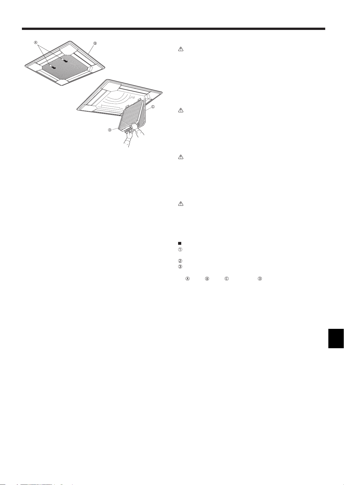
Filter removal
Caution:
• In removing the fi lter, precautions must be taken to protect your
eyes from dust. Also, if you have to climb up on a stool to do the
job, be careful not to fall.
• When the fi lter is removed, do not touch the metallic parts inside
the indoor unit, otherwise injury may result.
PLFY-P.NBMU-E Series
Pull the knob on the intake grille in the direction indicated by the ar-
row and it should open.
Open the intake grille.
Release the knob on the center edge of the intake grille and pull the
fi lter forward to remove the fi lter .
Knob Grille Intake Grille Filter
17
 Loading...