

Mitsubishi PLFY-P32VAM-E.UK, PLFY-P40VAM-E.UK, PLFY-P50VAM-E.UK, PLFY-P63VAM-E.UK, PLFY-P80VAM-E.UK Service Manual
...Page 1
SPLIT-TYPE, HEAT PUMP AIR CONDITIONERS
TECHNICAL & SERVICE MANUAL
Indoor unit
[Model names] [Service Ref.]
PLFY-P32VAM-E
PLFY-P32VAM-E.UK
PLFY-P40VAM-E
PLFY-P40VAM-E.UK
PLFY-P50VAM-E
PLFY-P50VAM-E.UK
PLFY-P63VAM-E
PLFY-P63VAM-E.UK
PLFY-P80VAM-E
PLFY-P80VAM-E.UK
PLFY-P100VAM-E
PLFY-P100VAM-E.UK
PLFY-P125VAM-E
PLFY-P125VAM-E.UK
July 2006
No. OC313
REVISED EDITION-B
Revision:
• RoHS PARTS LIST is added.
• Some descriptions have been
modified.
• Please void OC313 REVISED
EDITION-A.
Note:
• This manual does not cover
outdoor units.
When servicing them, please
refer to the outdoor unit’s
service manual.
• RoHS compliant products
have <G> mark on the spec
name plate.
• For servicing of RoHS com-
pliant products, refer to the
RoHS Parts List.
INDOOR UNIT
CONTENTS
1. SAFETY PRECAUTION··························2
2. PART NAMES AND FUNCTIONS··········6
3. SPECIFICATIONS···································8
4. 4-WAY AIR FLOW SYSTEM·················11
5. OUTLINES AND DIMENSIONS············14
6. WIRING DIAGRAM·······························15
7.
REFRIGERANT SYSTEM DIAGRAM
8. TROUBLE SHOOTING·························17
9. DISASSEMBLY PROCEDURE·············24
10. PARTS LIST··········································27
11. RoHS PARTS LIST·······························32
12. OPTIONAL PARTS ·······························37
·····16
Page 2
1
Do not use the existing refrigerant piping.
The old refrigerant and lubricant in the existing piping
contains a large amount of chlorine which may cause the
lubricant deterioration of the new unit.
Use “low residual oil piping”
If there is a large amount of residual oil (hydraulic oil, etc.)
inside the piping and joints, deterioration of the lubricant
will result.
Use ESTR , ETHER or HAB as the lubricant to
coat flares and flange connection parts.
If large amount of mineral oil enter, that can cause
deterioration of refrigerant oil etc.
Use liquid refrigerant to charge the system.
If gas refrigerant is used to seal the system, the composition
of the refrigerant in the cylinder will change and performance
may drop.
Do not use a refrigerant other than R407C.
If another refrigerant (R22, etc.) is used, the chlorine in the
refrigerant may cause the lubricant deterioration.
Use a vacuum pump with a reverse flow check valve.
The vacuum pump oil may flow back into the refrigerant
cycle and cause the lubricant deterioration.
Store the piping to be used during installation
indoors with keep both ends sealed until just
before brazing.
(Store elbows and other joints in a plastic bag.)
If dust, dirt, or water enters the refrigerant cycle,
deterioration of the oil and compressor trouble may result.
Ventilate the room if refrigerant leaks during
operation. If refrigerant comes into contact with
a flame, poisonous gases will be released.
SAFETY PRECAUTION
CAUTIONS RELATED TO NEW REFRIGERANT
Cautions for units utilizing refrigerant R407C
[1] Cautions for service
·After recovering the all refrigerant in the unit, proceed to working.
·Do not release refrigerant in the air.
·After completing the repair service, recharge the cycle with the specified amount of
liquid refrigerant.
2
Page 3
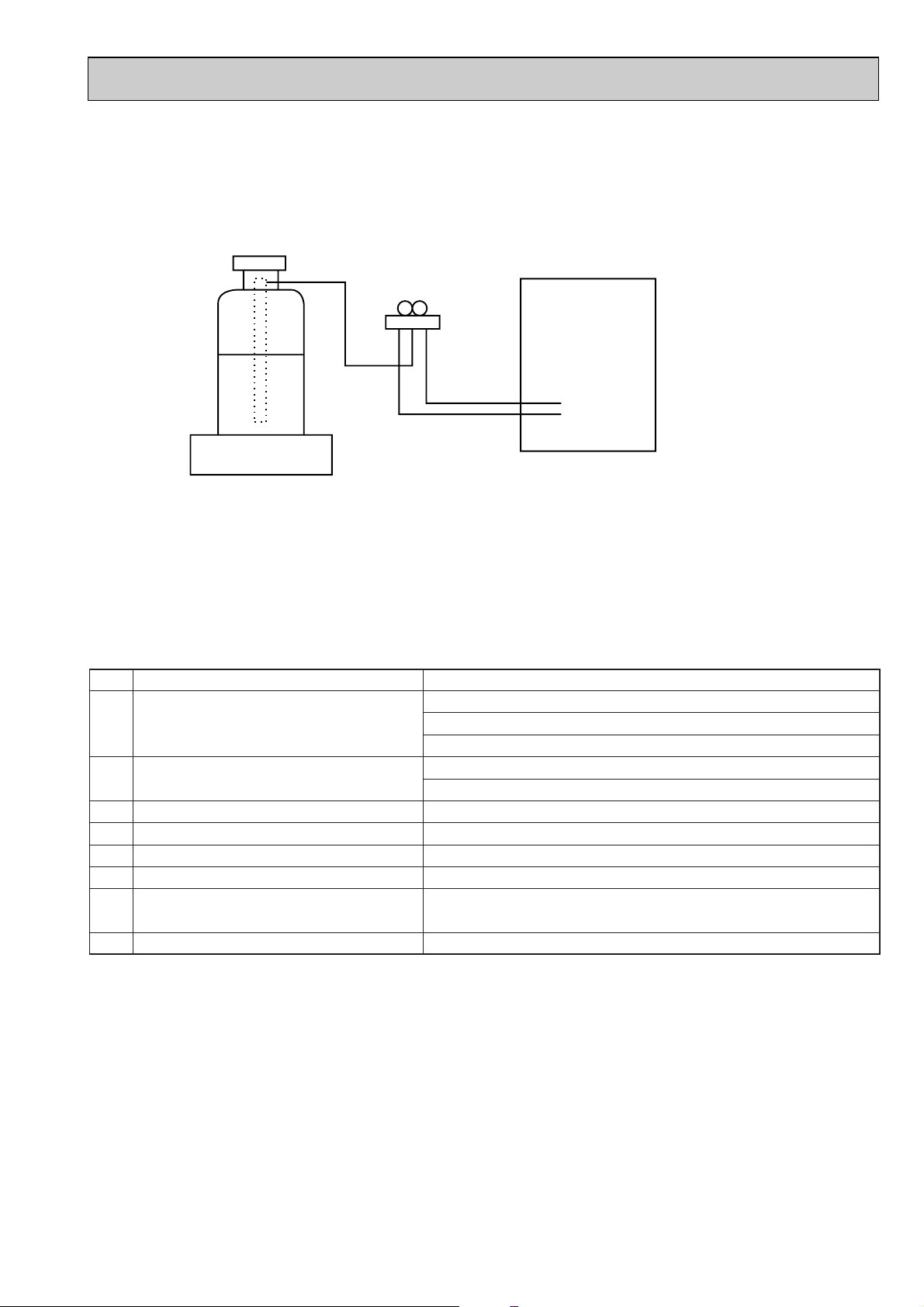
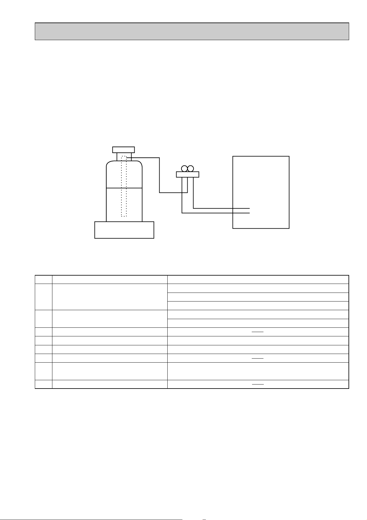
[2] Refrigerant recharging
Gravimeter
Unit
No. Tool name Specifications
1 Gauge manifold ·Only for R407C.
·Use the existing fitting SPECIFICATIONS. (UNF7/16)
·Use high-tension side pressure of 3.43MPa·G or over.
2 Charge hose ·Only for R407C.
·Use pressure performance of 5.10MPa·G or over.
—
3 Electronic scale
4 Gas leak detector ·Use the detector for R134a or R407C.
5 Adapter for reverse flow check. ·Attach on vacuum pump.
—
—
6 Refrigerant charge base.
7 Refrigerant cylinder. ·For R407C ·Top of cylinder (Brown)
·Cylinder with syphon
8 Refrigerant recovery equipment.
(1) Refrigerant recharging process
1Direct charging from the cylinder.
·R407C cylinder are available on the market has a syphon pipe.
·Leave the syphon pipe cylinder standing and recharge it.
(By liquid refrigerant)
(2) Recharge in refrigerant leakage case
·After recovering the all refrigerant in the unit, proceed to working.
·Do not release the refrigerant in the air.
·After completing the repair service, recharge the cycle with the specified amount of
liquid refrigerant.
[3] Service tools
Use the below service tools as exclusive tools for R407C refrigerant.
3
Page 4
Cautions for units utilizing refrigerant R410A
Store the piping to be used during installation
indoors and keep both ends of the piping sealed
until just before brazing. (Leave elbow joints, etc.
in their packaging.)
Use ester oil, ether oil or alkylbenzene oil (small
amount) as the refrigerant oil applied to flares
and flange connections.
Charge refrigerant from liquid phase of gas
cylinder.
If the refrigerant is charged from gas phase, composition
change may occur in refrigerant and the efficiency will be
lowered.
Do not use refrigerant other than R410A.
If other refrigerant (R22 etc.) is used, chlorine in refrigerant can cause deterioration of refrigerant oil etc.
Use a vacuum pump with a reverse flow check
valve.
Vacuum pump oil may flow back into refrigerant cycle and
that can cause deterioration of refrigerant oil etc.
Use the following tools specifically designed for
use with R410A refrigerant.
The following tools are necessary to use R410A refrigerant.
Keep the tools with care.
If dirt, dust or moisture enter into refrigerant cycle, that can
cause deterioration of refrigerant oil or malfunction of compressor.
Do not use a charging cylinder.
If a charging cylinder is used, the composition of refrigerant will change and the efficiency will be lowered.
Flare tool
Electronic refrigerant
charging scale
Vacuum pump adaptor
Size adjustment gauge
Gauge manifold
Torque wrench
Gas leak detector
Charge hose
Tools for R410A
If dirt, dust or moisture enter into refrigerant cycle, that can
cause deterioration of refrigerant oil or malfunction of compressor.
If large amount of mineral oil enter, that can cause deterioration of refrigerant oil etc.
Do not use the existing refrigerant piping.
The old refrigerant and lubricant in the existing piping
contains a large amount of chlorine which may cause the
lubricant deterioration of the new unit.
Use “low residual oil piping”
If there is a large amount of residual oil (hydraulic oil, etc.)
inside the piping and joints, deterioration of the lubricant
will result.
Ventilate the room if refrigerant leaks during
operation. If refrigerant comes into contact with
a flame, poisonous gases will be released.
4
Page 5
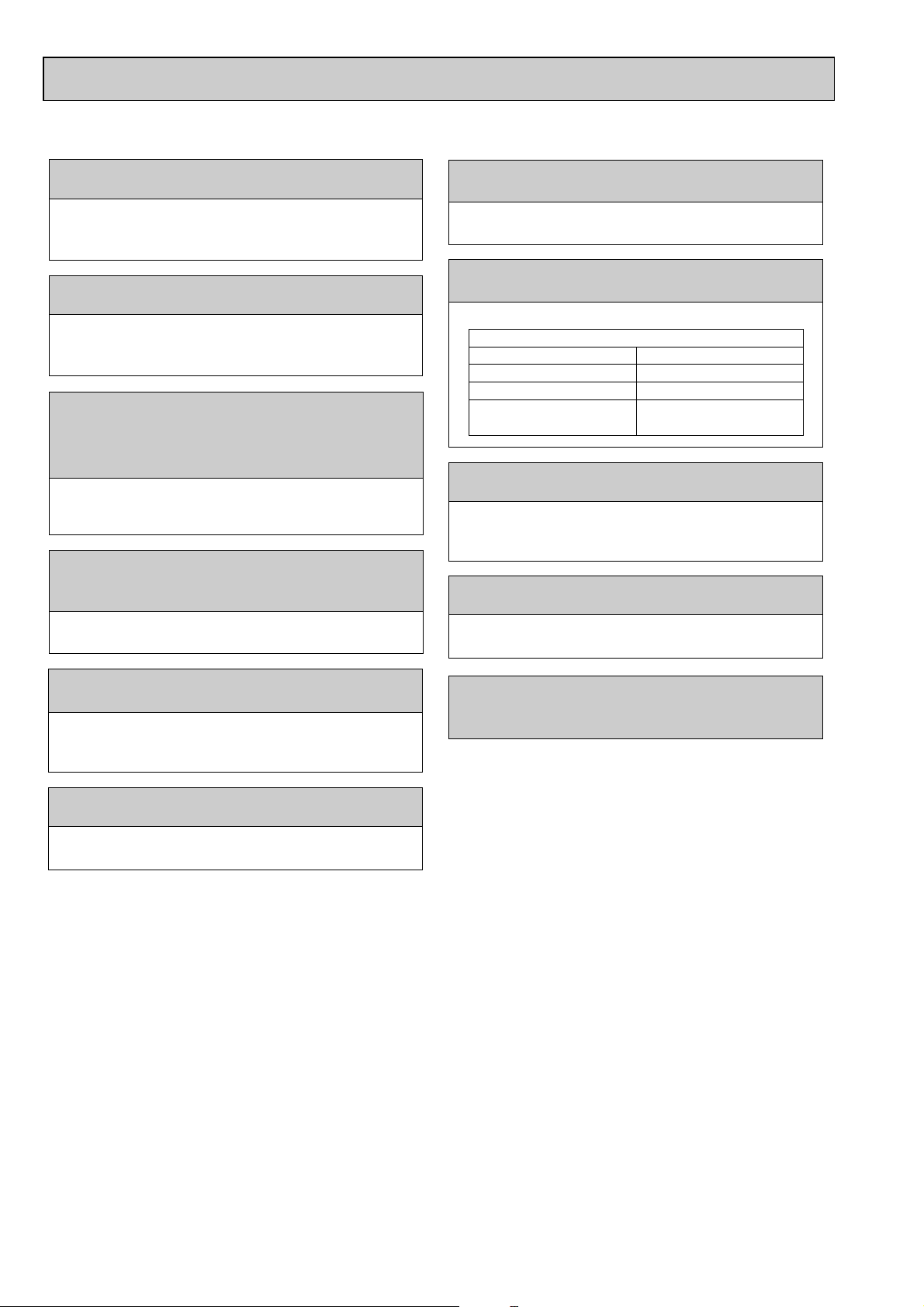
[1] Cautions for service
Gravimeter
Unit
(1) Perform service after collecting the refrigerant left in unit completely.
(2) Do not release refrigerant in the air.
(3) After completing service, charge the cycle with specified amount of refrigerant.
(4) When performing service, install a filter drier simultaneously.
Be sure to use a filter drier for new refrigerant.
[2] Additional refrigerant charge
When charging directly from cylinder
· Check that cylinder for R410A on the market is syphon type.
· Charging should be performed with the cylinder of syphon stood vertically. (Refrigerant is charged from liquid phase.)
[3] Service tools
Use the below service tools as exclusive tools for R410A refrigerant.
No. Specifications
1 Gauge manifold ·Only for R410A
·Use the existing fitting
·Use high-tension side pressure of 5.3MPa·G or over.
2 Charge hose ·Only for R410A
·Use pressure performance of 5.09MPa·G or over.
3 Electronic scale
4 Gas leak detector ·Use the detector for R134a, R407C or R410A.
5 Adaptor for reverse flow check ·Attach on vacuum pump.
6 Refrigerant charge base
7 Refrigerant cylinder ·Only for R410A Top of cylinder (Pink)
8 Refrigerant recovery equipment
specifications
Cylinder with syphon
. (UNF1/2)
5
Page 6
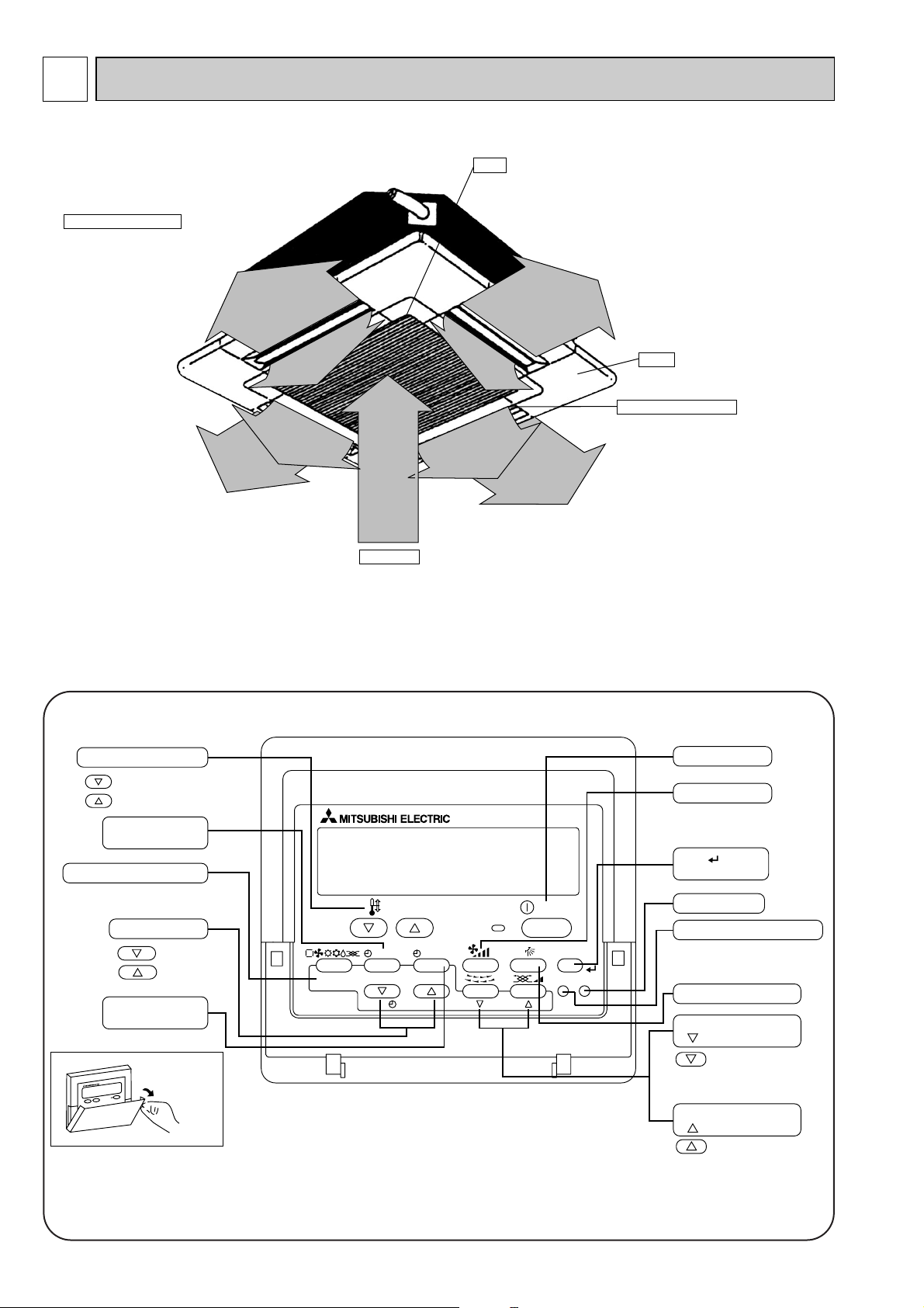
2
Auto Air Swing Vane
Disperses airflow up and
down and adjusts the angle
of airflow direction.
Grille
Filter
Remove dust and pollutants
from return air
Horizontal Air Outlet
Sets airflow horizontal automatically
during cooling or dehumidifying.
Air Intake
Returns air from room.
PAR-21MAA
ON/OFF
FILTER
CHECK
OPERATION
CLEAR
TEST
TEMP.
MENU
BACK DAY
MONITOR/SET
CLOCK
ON/OFF
Set Temperature buttons
Down
Up
Timer Menu button
(Monitor/Set button)
Mode button (Return button)
Set Time buttons
Back
Ahead
Timer On/Off button
(Set Day button)
Opening the
door.
ON/OFF button
Fan Speed button
Filter button
(<Enter> button)
Test Run button
Check button (Clear button)
Airflow Up/Down button
Louver button
( Operation button)
To preceding operation
number.
Ventilation button
(
Operation button)
To next operation number.
PART NAMES AND FUNCTIONS
● Indoor Unit
● Wired remote controller
On the controls are set, the same operation mode can be repeated by simply pressing the ON/OFF button.
● Operation buttons
6
Page 7
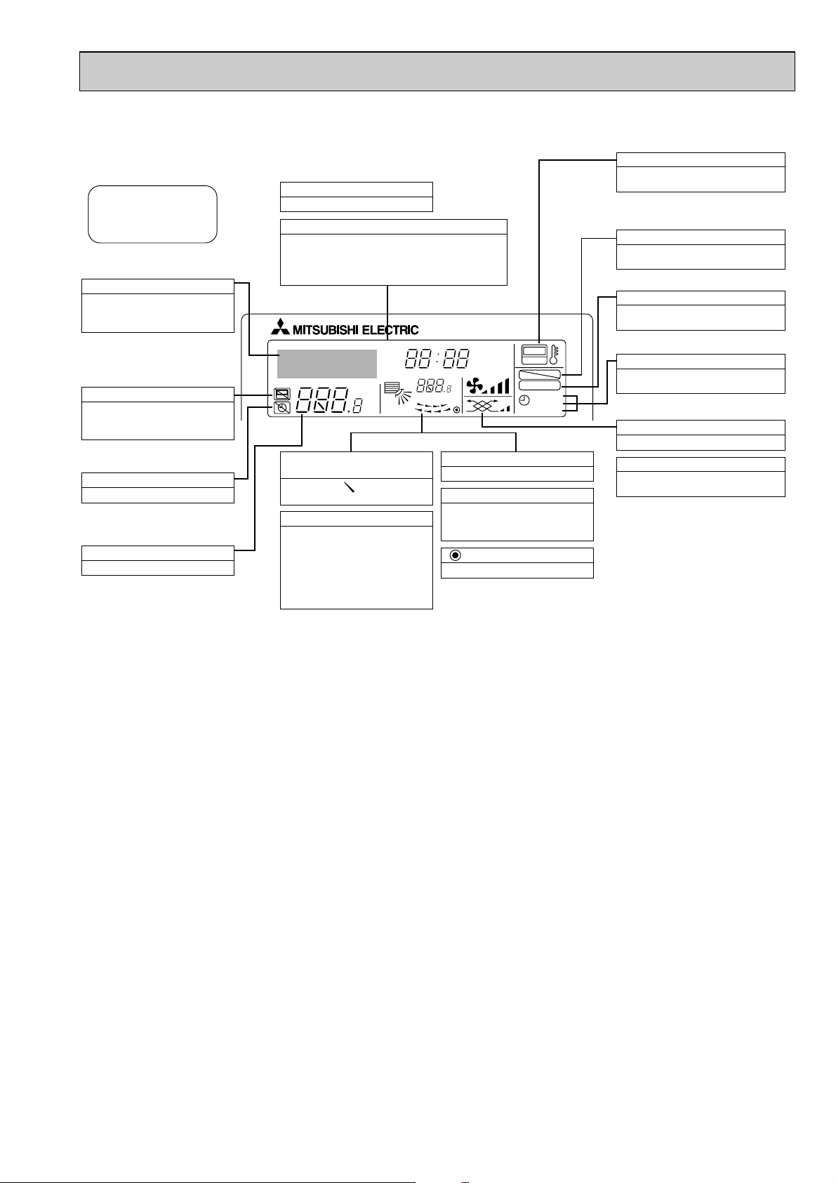
● Display
For purposes of this explanation,
all parts of the display are shown
as lit. During actual operation, only
the relevant items will be lit.
˚F˚C
˚F˚C
ERROR CODE
AFTER
TIMER
TIME SUN MON TUE WED THU FRI SAT
ON
OFF
Hr
AFTER
FILTER
FUNCTION
ONLY1Hr.
WEEKLY
SIMPLE
AUTO OFF
Identifies the current operation
Shows the operating mode, etc.
* Multilanguage display is sup-
ported.
“Centrally Controlled” indicator
Indicates that operation of the remote controller has been prohibited by a master controller.
“Timer Is Off” indicator
Indicates that the timer is off.
Temperature Setting
Shows the target temperature.
Day-of-Week
Shows the current day of the week.
Time/Timer Display
Shows the current time, unless the simple or Auto Off
timer is set.
If the simple or Auto Off timer is set, shows the time
remaining.
“Sensor” indication
Displayed when the remote controller
sensor is used.
“Locked” indicator
Indicates that remote controller buttons have been locked.
“Clean The Filter” indicator
Comes on when it is time to clean the
filter.
Timer indicators
The indicator comes on if the corresponding timer is set.
Up/Down Air Direction indicator
The indicator shows the direction of the outcoming airflow.
“One Hour Only” indicator
Displayed if the airflow is set to
weak and downward during COOL
or DRY mode. (Operation varies
according to model.)
The indicator goes off after one
hour, at which time the airflow direction also changes.
Room Temperature display
Shows the room temperature.
Louver display
Indicates the action of the swing
louver. Does not appear if the
louver is stationary.
(Power On indicator)
Indicates that the power is on.
Fan Speed indicator
Shows the selected fan speed.
Ventilation indicator
Appears when the unit is running in
Ventilation mode.
Caution
● Only the Power on indicator lights when the unit is stopped and power supplied to the unit.
● If you press a button for a feature that is not installed at the indoor unit, the remote controller will display the “Not Available”
message.
If you are using the remote controller to drive multiple indoor units, this message will appear only if he feature is not
present at the parent unit.
● When power is turned ON for the first time, it is normal that “PLEASE WAIT” is displayed on the room temperature indication (For max. 2minutes). Please wait until this “PLEASE WAIT” indication disappear then start the operation.
7
Page 8
3
Item
kW
kW
kW
kW
A
A
—
mm
mm
mm
—
—
k/min
Pa
kW
—
—
[mm(in.)
[mm(in.)
[mm
dB
kg
Cooling capacity
Power
Heat exchanger
Insulator
Air filter
Fan ✕ No
Air flow W3
Pipe
dimensions
Unit drain pipe size
Noise level W3
Product weight
Exterior
(munsell symbol)
Fan motor
output
External
static pressure
Liquid
side
Gas
side
Heating capacity
F
a
n
Dimensions
Height
Width
Depth
Electric characteristic
Input
Cooling
Heating
Cooling
Heating
Current
PLFY-P40VAM-E.UK
PLFY-P50VAM-E.UK
PLFY-P32VAM-E.UK
PLFY-P63VAM-E.UK
3.6
4.0
0.12
0.12
0.59
0.59
14-13-12-11
31-29-28-27
0.14
0.14
0.68
0.68
Unit : Galvanized sheets with gray heat insulation Grills : ABS resin Munsell<0.70Y 8.59/0.97>
258<30>
840<950>
840<950>
Cross fin
Turbo fan ✕ 1
16-14-13-12
0
0.070
Polyethylene sheet
PP honey comb fabric
O.D.32 (PVC pipe VP-25 connectable)
32-30-28-27
7.1
8.0
0.16
0.16
0.78
0.78
[15.88(5/8")
[9.52(3/8")
33-31-29-28
Single phase 220-230-240V 50Hz
Single phase 220V 60Hz
V
·Hz
[12.7(1/2") / [15.88(5/8")
(Compatible)
[6.35(1/4")/[9.52(3/8")
(Compatible)
4.5
5.0
5.6
6.3
18-16-15-14
[12.7(1/2")
[6.35(1/4")
24<5>22<5>
SPECIFICATIONS
3-1. SPECIFICATIONS
Note 1. Rating conditions(JIS B 8616)
Note 2. The number indicated in < > is just for the grille.
W 3. Air flow and the noise level are indicated as High-Medium1-Medium2-Low.
Cooling : Indoor : D.B. 27°C W.B. 19.0°C
Heating : Indoor : D.B. 20°C
outdoor : D.B. 35°C
outdoor : D.B. 7°C W.B. 6°C
8
Page 9
Item
kW
kW
kW
kW
A
A
—
mm
mm
mm
—
—
k/min
Pa
kW
—
—
[mm(in.)
[mm(in.)
[mm
dB
kg
Cooling capacity
Power
Heat exchanger
Insulator
Air filter
Fan ✕ No
Air flow W3
Pipe
dimensions
Unit drain pipe size
Noise level W3
Product weight
Exterior
(munsell symbol)
Fan motor
output
External
static pressure
Liquid
side
Gas
side
Heating capacity
F
a
n
Dimensions
Height
Width
Depth
Electric characteristic
Input
Cooling
Heating
Cooling
Heating
Current
PLFY-P80VAM-E.UK
PLFY-P100VAM-E.UK PLFY-P125VAM-E.UK
9.0
10.0
0.18
0.18
0.86
0.86
258<30>
22-20-18-16
0.070
15.88(5/8")
37-35-32-30
24<5>
11.2
12.5
0.30
0.30
1.43
1.43
Unit : Galvanized sheets with gray heat insulation Grills : ABS resin Munsell<0.70Y 8.59/0.97>
840<950>
840<950>
Cross fin
Turbo fan ✕ 1
27-25-22-19
0
Polyethylene sheet
PP honey comb fabric
9.52(3/8")
O.D.32 (PVC pipe VP-25 connectable)
41-39-36-33
14.0
16.0
0.34
0.34
1.64
1.64
298<30>
0.120
29-27-24-21
43-41-38-35
Single phase 220-230-240V 50Hz
Single phase 220V 60Hz
V
·Hz
32<5>
[15.88(5/8") / [19.05(3/4")
(Compatible)
Note 1. Rating conditions(JIS B 8616)
Note 2. The number indicated in < > is just for the grille.
W 3. Air flow and the noise level are indicated as High-Medium1-Medium2-Low.
Cooling : Indoor : D.B. 27°C W.B. 19.0°C
Heating : Indoor : D.B. 20°C
outdoor : D.B. 35°C
outdoor : D.B. 7°C W.B. 6°C
9
Page 10
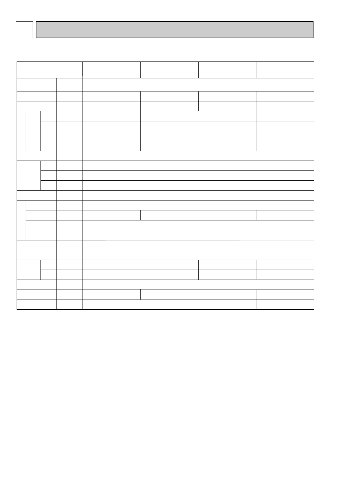
3-2. ELECTRICAL PARTS SPECIFICATIONS
Parts name
Model
Symbol
TH21
TH22
TH23
FUSE
MF
C
MV
DP
DS
LEV
H2
TB2
TB5
TB15
Resistance 0:/15k", 10:/9.6k", 20:/6.3k", 25:/5.4k", 30:/4.3k", 40:/3.0k"
Resistance 0:/15k", 10:/9.6k", 20:/6.3k", 25:/5.4k", 30:/4.3k", 40:/3.0k"
Resistance 0:/15k", 10:/9.6k", 20:/6.3k", 25:/5.4k", 30:/4.3k", 40:/3.0k"
250V 6.3A
240V 21.8W
(L, N, ;) Rated to 330V 30A W
(M1, M2, S) Rated to 250V 20A W
(1, 2) Rated to 250V 10A W
Liquid pipe thermistor
Gas pipe thermistor
Fan motor capacitor
Vane motor
Drain-up mechanism
Drain sensor
Linear expansion valve
PLFY-P40VAM-E.UKPLFY-P32VAM-E.UK PLFY-P50VAM-E.UK PLFY-P63VAM-E.UK
Room temperature
thermistor
Fuse
(Indoor controller board)
Fan motor
(with inner-thermostat)
Inner-thermostat
Electric heater
(Condensation proof)
Power supply terminal
block
Transmission terminal
block
MA remote controller
terminal block
6-pole OUTPUT 70W
D17B6P70MS
MSBPC20M04
DC12V 300
"
/phase
PLD-12230ME-1
INPUT 12/10.8W 24R/Hr
Thermistor resistance 0:/6k", 10:/3.9k", 20:/2.6k", 25:/2.2k", 30:/1.8k", 40:/1.3k"
DC12V Stepping motor drive port dimension 5.2" (0~2000pulse)
EDM-40YGME
OFF 130: i 5:
ON 90: i 20:
3.0+ ✕ 440V
W Note : Refer to WIRING DIAGRAM for the supplied voltage.
10
Page 11
Model
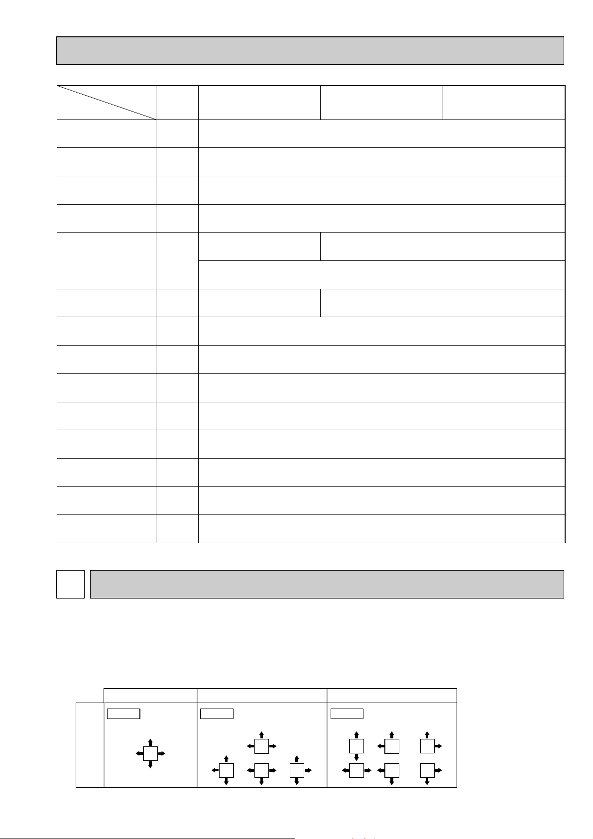
Blowout direction
pattern
4-direction<Table 1> 3-direction 2-direction Note1.
For 3 and 2-directional,
please use the air outlet
shutter plate (option).
Pattern 1 Factory setting Pattern 4 One air outlet
fully closed
Pattern 6 Two air outlet
fully closed
Parts name
Room temperature
thermistor
Symbol
TH21
PLFY-P100VAM-E.UKPLFY-P80VAM-E.UK PLFY-P125VAM-E.UK
Resistance 0:/15k", 10:/9.6k", 20:/6.3k", 25:/5.4k", 30:/4.3k", 40:/3.0k"
Liquid pipe thermistor
Gas pipe thermistor
Fuse
(Indoor controller board)
Fan motor
(with inner-thermostat)
Fan motor capacitor
Vane motor
Drain-up mechanism
Drain sensor
Linear expansion valve
Electric heater
(Condensation proof)
TH22
TH23
FUSE
MF
C
MV
DP
DS
LEV
H2
Resistance 0:/15k", 10:/9.6k", 20:/6.3k", 25:/5.4k", 30:/4.3k", 40:/3.0k"
Resistance 0:/15k", 10:/9.6k", 20:/6.3k", 25:/5.4k", 30:/4.3k", 40:/3.0k"
250V 6.3A
6-pole OUTPUT 70W
D17B6P70MS
Inner-thermostat
3.5+ ✕ 440V 7.0+ ✕ 440V
MSBPC20M04
DC12V 300
PLD-12230ME-1
INPUT 12/10.8W 24R/Hr
Thermistor resistance 0:/6k", 10:/3.9k", 20:/2.6k", 25:/2.2k", 30:/1.8k", 40:/1.3k"
DC12V Stepping motor drive port dimension 5.2" (0~2000pulse)
EDM-80YGME
240V 21.8W
6-pole OUTPUT 120W
D176P120MS
OFF 130: i 5:
ON 90: i 20:
"
/phase
Power supply terminal
block
Transmission terminal
block
MA remote controller
terminal block
4
4-WAY AIR FLOW SYSTEM
TB2
TB5
TB15
(L, N, ;) Rated to 330V 30A W
(M1, M2, S) Rated to 250V 20A W
(1, 2) Rated to 250V 10A W
W Note : Refer to WIRING DIAGRAM for the supplied voltage.
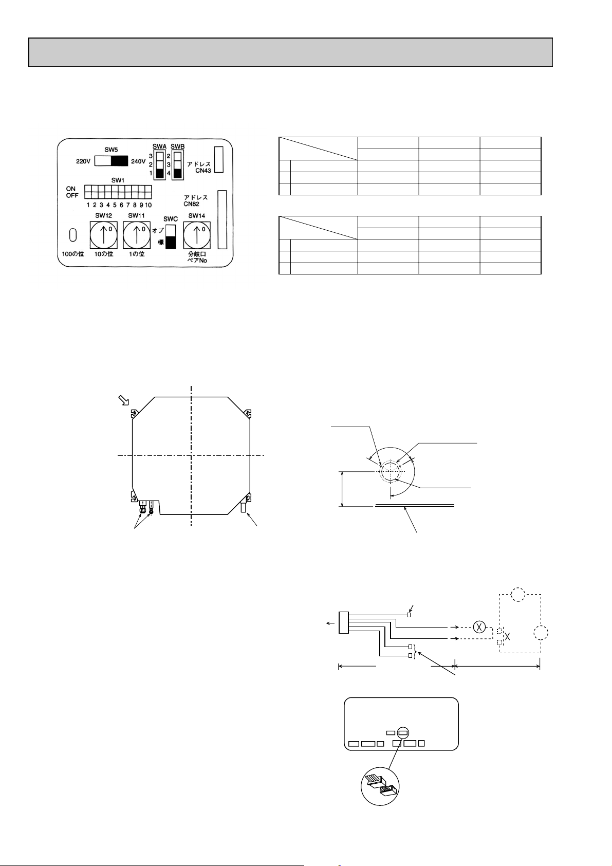
4-1. PLACEMENT OF THE AIR OUTLETS
• For this grille, the blowout direction comes in 11 patterns.
Also, by setting the dip switches (SWA and SWB) on the circuit board to the appropriate settings, you can adjust the air flow
and speed. Select the settings from Table according to the location in which you want to install the unit.
1) Decide on the pattern of the airflow direction.
11
Page 12
A.B
SW5
240V220V
SWA
3
2
1
SWB
2
3
4
1
2
3
4
(RED)
ADDRESS
CN43
(RED)
ADDRESS
CN82
1
Standard
2.7m
3.0m
3.3m
2
High ceiling 1
3.0m
3.3m
3.5m
3
High ceiling 2
3.5m
3.5m
—
1
2
3
4
5
6
7
8
CONNECTION
No.
SW14
0
SWC
SW1
87654321
OFF
ON
10
9
00
SW11
SW12
1ST.DIGIT2ND.DIGIT
3RD.DIGIT
4 direction
3 direction
2 direction
SWA
SWB
PLFY-P32·P40·P50·P63·P80VAM-E
PLFY-P100·P125VAM-E
4
3
2
1
Standard
3.2m
3.6m
4.0m
2
High ceiling 1
3.6m
4.0m
4.2m
3
High ceiling 2
4.2m
4.2m
—
4 direction
3 direction
2 direction
SWA
SWB
4
3
2
2) According to the number of air outlets and height of the ceiling to install the unit, be sure to set the up switches
Fresh air intake hole
Fresh air intake hole diagram
3 - {2.8
Burring hole
{125
Burring hole pitch
{100
(Cut out hole)
Refrigerant pipe Drain pipe
Ceiling surface
120
_
120_
w158
CN51
Multiple remote
controller adapter
PAC-SA88HA-E
Indoor controller board
Distance between indoor
controller board and relay
must be within 10m.
Be sure to secure insulation
material by tape and such
5
Green
Yellow
Orange
Connector (5P)
Package side
Multiple remote
controller adapter
PAC-SA88HA-E
Be sure to secure insulation
material by tape and such
Installation at site
CN51
on
indoor
controller
board
Red
Brown
1
~
CN51
MB
(SWA, SWB) on the circuit board to the appropriate setting.
• Correspondence of ceiling heights to numbers of air outlets.
4-2. FRESH AIR INTAKE (Installation of site)
• At the time of installation, use the duct holes (cutout) located at the positions shown in following diagram, as and when required.
Note :
Be sure to add135mm to the dimensions in the diagram that are marked with a “w” if installing a multi function casement
(Option)
4-3. INTERLOCKING OPERATION METHOD
WITH DUCT FAN (Booster fan)
• Whenever the indoor unit is operating, the duct fun also
operates.
(1)Connect the optional multiple remote controller
adapter(PAC-SA88HA-E)to the connector CN51 on
the indoor controller board.
(2)Drive the relay after connecting the 12V DC relay
between the Yellow and Orange connector lines.
MB: Electromagnetic switch power relay for duct fan.
X: Auxiliary relay (For DC 12V, coil rating : 1.0W or below)
12
Page 13

]
4-4. FRESH AIR INTAKE AMOUNT & STATIC PRESSURE CHARACTERISTICS
Q
0
B
A
C
1
Curve in the
graphs.
Duct characteristics
at site
Q
A
EC
2
Q
Qa
AD
3
ll
PLFY-P32 · P40 · P50 · P63 · P80VAM-E
Multifunction casement + Standard filter
Multifunction casement + High efficiency filter
Static pressure [Pa]
50
1 2 3 4 5 6
0
-50
-100
-150
-200
Taking air into the unit
Static pressure [Pa]
50
1 2 3 4 5 6
0
-50
-100
-150
-200
1 intake
Air flow [m
2 intakes
Air flow [m
3
/min]
3
/min]
Static pressure [Pa]
50
0
-50
-100
-150
-200
How to read curves
1 2 3 4 5 6
1 intake
Q…Planned amount of fresh air intake
A…Static pressure loss of fresh air
intake duct system with air flow
amount Q
B…Forced static pressure at air condi-
tioner inlet with air flow amount Q
C…Static pressure of booster fan with
air flow amount Q
D…Static pressure loss increase
amount of fresh air intake dust system for air flow amount Q <Pa>
E…Static pressure of indoor unit with air
flow amount Q
Qa…Estimated amount of fresh air
intake with out D <m3/min>
Air flow [m
2 intakes
3
/min]
<m
3
/min>
<Pa>
<Pa>
<Pa>
<Pa>
22
PLFY-P100 · P125VAM-E
Multifunction casement + Standard filter Multifunction casement + High efficiency filter
Static pressure [Pa]
50
0
-50
-100
-150
-200
1 2 3 4 5 6 7 8 9
2 intakes
1 intake
Static pressure [Pa]
Air flow
3
[m
/min
-50
-100
-150
-200
50
1 2 3 4 5 6 7 8 9
0
1 intake
Air flow
3
/min]
[m
2 intakes
Taking air into the unit
Static pressure [Pa]
50
1 2 3 4 5 6 7 8 9
0
Air flow [m
3
/min]
-50
-100
-150
-200
13
Page 14

5
Air outlet hole
Vane motor
Auto vane
Drain hole
Grille
Drain pipe
VP-25connection
(O.D.{32)
Branch duct hole
(Cut out hole)
Ceiling surface
Suspension bolt pitch
Ceiling hole
Branch
duct ho
Suspension bolt pitch
Ceiling hole
Air outlet hole
Air intake hole
411
Air intake hole
Air intake grille
Power line entry
Suspension bolt lower edge
Suspension bolt
M10 or W3/8
Control wire entry
Feeding hole
(Drain pump)
577
374286
840
197 159
60
17
+5
0
30
190
159
605
159192
170
140
50~70
98
89
840
860~91020~45 20~45
20~4520~45
Fresh air intake
Branch duct hole
860~910
810
159
16
105
A
B
77 51
M
M
M
1
2
M
950
51 77
950
577
411
Terminal block
{175
{150
14 - {2.8
Burring hole
Models 1 Liquid Pipe 2 Gas Pipe
PLFY-P32VAM-E.UK
PLFY-P40VAM-E.UK
PLFY-P50VAM-E.UK
PLFY-P63VAM-E.UK
PLFY-P80VAM-E.UK
PLFY-P100VAM-E.UK
PLFY-P125VAM-E.UK
241
281
A
258
298
B
350
90
70_
100 100 90
100
130
155
167
[6.35
[9.52
[12.7
[15.88
[15.88/[19.05
(Compatible)
[12.7 / [15.88
(Compatible)
[6.35 / [9.52
(Compatible)
High efficiency filter & Multi function
17
+5
0
135
Detail drawing of fresh air intake
3 - {2.8
Burring hole
{125
Burring hole pitch
{100
(Cut out hole)
Ceiling surface
Liquid pipe
Gas pipe
120
_
120
_
w158
NOTES :
1. When servicing, electrical parts box may be disassembled.
Make the wires loose enough when connecting heater power
supply wire, remote controller wire, and indoor/outdoor unit connecting wire.
2. Detaching corner panel makes it possible to adjust the height
of body with the grille attached.
3. Caution for attaching optional Muliti function casement and
optional High efficiency filter :
1) Space behind the ceiling shall be high enough as specified
in the table below.
2) Add extra 135mm to the dimensions of w in the figure.
3) Mount both High efficiency filter and Multi function casement together.
4. When connecting branch duct, be sure to insulate the heat.
(Otherwise, it causes dew to from or drop.)
P32-P80
P100-P125
400
440
OUTLINES AND DIMENSIONS
PLFY -P32VAM-E.UK PLFY-P80VAM-E.UK
PLFY -P40VAM-E.UK PLFY-P100VAM-E.UK
PLFY -P50VAM-E.UK PLFY-P125VAM-E.UK
PLFY -P63VAM-E.UK
Unit : mm
14
Page 15

DAMPERCN27
MA-REMOTE CONTROLLER
TB15
DRAIN WATER LIFTING-UP MACH.
SYMBOL NAMESYMBOL NAME
VARISTORZNR
A.B
LEV
LINEAR EXPANSION VALVE
CIRCUIT BOARD
SW11
SW12
SW14
SWB
SW1
SW5
SWITCH
SWC
VOLTAGE SELECTION
FUNCTION SETTING
ADDRESS SETTING 1ST DIGIT
ADDRESS SETTING 2ND DIGIT
CONNECTION NO.
CEILING HEIGHT SELECTOR
DISCHARGE OUTLET NUMBER
SELECTOR
OPTION SELECTOR
NAMESYMBOL
TRANSMISSION
POWER SUPPLY
BLOCK
TERMINAL
TB5
TB2
DEW PREVENTION HEATER
VANE MOTOR
FAN MOTOR(WITH INNER THERMO.)
CAPACITOR(FAN MOTOR)
H2
MV
C
MF
DRAIN SENSORDS
DP
DRAIN PUMP
FAN MOTORX4
FUSE
FAN PHASE CONTROL
F.C
FUSE(6.3A/250V)
INDOOR CONTROLLER BOARD
MODEL SELECTION
FUNCTION SETTING
CAPACITY CODE
REMOTE INDICATION
HA TERMINAL-A
CENTRALLY CONTROL
REMOTE SWITCH
SWITCH
SW4
SW3
SW2
CN52
CN51
CN41
CN32
HUMIDIFIERCONNECTORCN25
I.B
TH21
PIPE TEMP.DETECTION/GAS
PIPE TEMP.DETECTION/LIQUID
ROOM TEMP.DETECTIONTHERMISTOR
(0:/15k",25:/5.4k")
(0:/15k",25:/5.4k")
(0:/15k",25:/5.4k")
TH23
TH22
AUX.RELAY
X1
INDOOR POWER BOARD
P.B
LED2
POWER SUPPLY(I.B)
POWER SUPPLY(I.B)
LED1
[LEGEND]
SWA
2.In case of using MA-Remote controller, please connect to TB15.(Remote controller wire is non-polar.)
3.In case of using M-NET, please connect to TB5.(Transmission line is non-polar.)
1.At servicing for outdoor unit, always follow the wiring diagram of outdoor unit.
NOTES:
4.Symbol[S] of TB5 is the shield wire connection.
5.Symbols used in wiring diagram above are, :terminal block, :connecter.
6.The setting of the SW2 dip switches differs in the capacity. For the detail, refer to the table below.
7.Please set the switch SW5 according to the power supply voltage.
Set SW5 to 240V side when the power supply is 230 and 240 volts.
When the power supply is 220 volts, set SW5 to 220V side.
LED2
LED1
Mark
Power supply for
MA-Remote controller
Main power supply
Main power supply(Indoor unit:220-240V)
power on ➔ lamp is lit
Meaning
Power supply for MA-Remote controller
on ➔ lamp is lit
Function
LED on indoor controller board for service
A.B
91012345678
ON
OFF
CN43
ADDRESS
(RED)
(RED)
CN82
ADDRESS
240V
220V
No.
CONNECTION
3RD.DIGIT 2ND.DIGIT 1ST.DIGIT
3
8
SW14
SWC
SW11SW12
SW1
SW5
SWA SWB
2
1
2
3
4
1
2
3
4
5
6
7
1
2
3
4
00
0
O
OFF
ON
OFF
ON
OFF
ON
OFF
ON
OFF
ON
OFF
ON
ON
OFF
OFF
ON
OFF
ON
10
987654321
10
987654321
SW3
P125VAM
654321
P100VAM
654321
P80VAM
654321
P63VAM
654321
P50VAM
P40VAM
P32VAM
<fig:✻1>
SW2
123456
654321
654321
TH21TH23 TH22
BLK
BLK
BLK
BLK
BLK
BLK
DS
LEV
WHT
RED
YLW
ORN
BRN
BLU
123456
M1
M2
TB5
(SHIELD)
1
2
TB15
S
}
BC CONTROLLER
TO OUTDOOR UNIT
REMOTE CONTROLLER
DC24-30V
BLU
BLU
ORN
ORN
}
TO MA-REMOTE
CONTROLLER
DC8.7-13V
TB2
C
TB5
TB15
(For Control box)
Position of TB2,TB5,TB15,C.
GRILLE
MV MV MV MV
5555
5
H2
YLW
YLW
1236
7
4895
10
MF
C
RED
WHT
BLK
I.B
123
123
RED
BLU
POWER
CND
(RED)
FUSE
ZNR
13
BRN
BRN
DP
12
YLW
YLW
X1
D.U.M
CNP
(BLU)
X1
13
WHT
BLK
WHT
BLK
P.B
(DC13.1V)
CN2S (WHT)
2
1
TRANS
CNSK(RED)
3
2
1
(AC220-240V)
TB2
L
N
220V 60Hz
50Hz~/N 220-240V
POWER SUPPLY
(15A)
BREAKER
FUSE(15A)
PULL BOX
INDOOR UNIT
TO NEXT
GRN/YLW
BLU
RED
31
CN2M
(BLU)
M-NET
41
HA
(WHT)
LIQUID
CN21
(RED)
INTAKE
CN20
(BLK)
GAS
CN29
(WHT)
DRAIN
CN31
(WHT)
LEV
CN60
(WHT)
REMOTE
SWITCH
CN32
CN41
(WHT)
(WHT)
CENTRALLY
CONTROL
CN51
(GRN)
REMOTE
INDICATION
CN52
(RED)
ADDRESS
CN42
(RED)
ADDRESS
CN81
(GRN)
VANE
CN6V
HUMIDIFIER
CN25
(WHT)
CN3A
(BLU)
REMOCON
(RED)
DAMPER
CN27
ON
OFF
ON
OFF
5
5
SW4
3214
1
4
8
6
51
SW3
SW2
See fig:✻1
FAN
(WHT)
FC
X4
X4
POWER
CNDK
(RED)
12
CN2D
(WHT)
LED1
12
1
2
LED2
12122
123
321654
12345 109876123456
654321
654321 123487
51
1
3
21
135
13
6
WIRING DIAGRAM
PLFY-P32VAM-E.UK PLFY-P80VAM-E.UK
PLFY-P40VAM-E.UK PLFY-P100VAM-E.UK
PLFY-P50VAM-E.UK PLFY-P125VAM-E.UK
PLFY-P63VAM-E.UK
w
w The part name of symbol “I.B” is “SPCB”.
15
Page 16

7 REFRIGERANT SYSTEM DIAGRAM
Strainer (#50mesh)
Strainer (#100mesh)
Strainer1 (#50mesh)
Strainer2 (#100mesh)
Heat exchanger
Room temparature thermistor TH21
Gas pipe thermistor TH23
Liquid pipe thermistor TH22
Linear expansion valve
Gas pipe
Liquid pipe
Flare connection
Gas pipe
Liquid pipe
PLFY-P32, P40VAM-E
[12.7(1/2'')
[6.35(1/4'')
PLFY-P50VAM-E
[12.7(1/2'')/[15.88(5/8'')
[6.35(1/4'')/[9.52(3/8'')
PLFY-P63, P80VAM-E
[15.88(5/8'')
[9.52(3/8'')
PLFY-P100, P125VAM-E
[15.88(5/8'')/[19.05(3/4'')
[9.52(3/8'')
Item
Capacity
PLFY -P32VAM-E.UK PLFY-P80VAM-E.UK
PLFY -P40VAM-E.UK PLFY-P100VAM-E.UK
PLFY -P50VAM-E.UK PLFY-P125VAM-E.UK
PLFY -P63VAM-E.UK
16
Page 17

8
Parts name Check points
Disconnect the connector then measure the resistance using a tester.
(Surrounding temperature 10:~30:)
Disconnect the connector then measure the resistance valve using a tester.
Measure the resistance between the terminals using a tester.
(Surrounding temperature 20:~30:)
Measure the resistance between the terminals using a tester.
(Surrounding temperature 20:~30:)
Measure the resistance after 3 minutes have passed since the power supply was intercepted.
(Surrounding temperature 0:~60:)
Vane motor(MV)
Linear expansion
valve(LEV)
Drain pump(DP)
Drain sensor(DS)
Refer to the next page for the details.
Refer to the next page for the details.
Room temperature
thermistor (TH21)
Liquid pipe thermistor
(TH22)
Gas pipe thermistor
(TH23)
1
2
Yellow
Yellow
1
2
3
Normal
4.3k"~9.6k"
Abnormal
Open or short
Abnormal
Open or short
Normal
0.6k"~6.0k"
Abnormal
Open or short
Normal
150k" i10%
White-Red Yellow-Brown Orange-Red Blue-Brown
NormalConnector Abnormal
300" Open or short
Normal Abnormal
290" Open or short
Orange
Red
White
Blue
Brown
Yellow
M
Orange
Red
White
Red — Yellow
Red — Blue
Red — Orange
Red — White
Blue
Yellow
Measure the resistance between the terminals using a tester.Fan motor(MF)
1
1
2
2
3
3
Red
White
Black
Relay connector
Relay connector
Protector
32, 40, 50, 63, 80
87.2"
104.1"
Abnormal
Open or short
100, 125
28.7"
41.6"
Red-Black
White-Black
Motor terminal
or
Relay connector
Normal
PLFY-P·VAM-E.UK
M
Refer to the next
page for the details.
TROUBLE SHOOTING
8-1. HOW TO CHECK THE PARTS
PLFY-P32VAM-E.UK PLFY-P80VAM-E.UK
PLFY-P40VAM-E.UK PLFY-P100VAM-E.UK
PLFY-P50VAM-E.UK PLFY-P125VAM-E.UK
PLFY-P63VAM-E.UK
17
Page 18

<Thermistor characteristic graph>
-20 0 20406080
< Thermistor for drain sensor >
Temperature (:)
0
1
2
3
4
5
6
7
8
9
10
Resistance (K")
Thermistor for
lower temperature
Room temperature thermistor(TH21)
Liquid pipe temperature thermistor(TH22)
Gas pipe temperature thermistor(TH23)
Thermistor R0=15k' ±3%
Fixed number of B=3480K ± 2%
Rt=15exp { 3480( ) }
1
273+t
1
273
0: 15k'
10: 9.6k'
20: 6.3k'
25: 5.4k'
30: 4.3k'
40: 3.0k'
Thermistor for
drain sensor
Thermistor R0=6.0k' ±5%
Fixed number of B=3390K ±2%
< Thermistor for lower temperature >
50
40
30
Resistance (K")
20
10
0
-20 -10 0 10 20 30 40 50
Temperature (:)
Rt=6exp { 3390( ) }
1
273+t
1
273
0: 6.0k'
10: 3.9k'
20: 2.6k'
25: 2.2k'
30: 1.8k'
40: 1.3k'
60: 0.6k'
Linear expansion valve
① Operation summary of the linear expansion valve.
• Linear expansion valves open/close through the use of a stepping motor after receiving the pulse signal from the indoor
controller board.
• Valve position can be changed in proportion to the number of pulse signals.
<Connection between the indoor controller board and the linear expansion valve>
Controller board
Relay connector
Note : Since the number of the connector at the controller board side and the relay connector are different, follow the color of
the lead wire.
Linear expansion valve
M
[1
1
Red
White
5
[4
[2
[3
Orange
Blue
4
Brown
6
Yellow
2
3
5
1
3
4
6
Brown
Red
Blue
Orange
Yellow
White
Connector(CN60)
18
DC12V
62
5
4
3
2
1
Drive circuit
[4
[3
[2
[1
Page 19

<Output pulse signal and the valve operation>
D
A
E
B
C
Open
Open
Extra tightening (200~800 pulse)
Pulse number
Outdoor unit R410A model : 1400 pulse
Outdoor unit R22/R407C model : 2000 pulse
Opening a valve
all the way
Close
Close
Valve position (capacity)
Thermistor
(Liquid pipe)
Linear
expansion
valve
Output
(Phase)
{1
{2
{3
{4
Linear expansion valve operation
➁
1
ON
ON
OFF
OFF
2
OFF
ON
ON
OFF
Output
3
OFF
OFF
ON
ON
4
ON
OFF
OFF
ON
Closing a valve : 1 → 2 → 3 → 4 → 1
Opening a valve : 4 → 3 → 2 → 1 → 4
The output pulse shifts in above order.
❈ 1. When linear expansion valve operation stops, all output phase
become OFF.
2. At phase interruption or when phase does not shift in order,
motor does not rotate smoothly and motor will locks and vibrates.
❈ When the switch is turned on, 2200 pulse closing valve signal
will be send till it goes to point
A in order to define the valve
position.
When the valve moves smoothly, there is no noise or vibration
occurring from the linear expansion valves : however, when the
pulse number moves from E to A or when the valve is locked,
more noise can be heard than in a normal situation.
❈ Noise can be detected by placing the ear against the screw
driver handle while putting the screw driver tip to the linear
expansion valve.
Trouble shooting
➂
Symptom
Operation circuit failure of the micro
processor.
Linear expansion
valve mechanism is
locked.
Short or breakage of
the motor coil of the
linear expansion
valve.
Valve doesn't close
completely.
Wrong connection of
the connector or
contact failure.
Check points
Disconnect the connector on the controller board, then con-
nect LED for checking.
When power is turned on, pulse signals will output for 10 sec-
onds. There must be some defects in the operation circuit if
the LED does not light while the signals are output or keeps
lighting even after the signals stop.
Motor will idle and make a ticking noise when the motor is
operated while the linear expansion valve is locked. This
ticking sound is the sign of the abnormality.
Measure the resistance between each coil (white-red, yellow-
brown, orange-red, blue-brown) using a tester. It is normal if
the resistance is in the range of 150Ω ±10%.
To check the linear expansion valve, operate the indoor unit
in fan mode and at the same time operate other indoor units
in cooling mode, then check the pipe temperature <liquid
it means the valve is not closed all the way. It is not necessary to exchange the linear expansion valve, if the leakage is
small and not affecting normal operation.
Check the color of lead wire and missing terminal of the con-
nector.
pipe temperature> of the indoor unit by the
outdoor multi controller board operation
monitor. During fan operation, linear
expansion valve is closed completely and if
there is any leaking, detecting temperature
of the thermistor will go lower. If the detected temperature is much lower than the temperature indicated in the remote controller,
19
Countermeasures
6
5
4
3
2
LED1k"
1
Exchange the indoor con-
troller board at drive circuit
failure.
Exchange the linear
expansion vale.
Exchange the linear
expansion valve.
If large amount of thermis-
tor is leaked, exchange the
linear expansion valve.
Disconnect the connector
at the controller board,
then check the continuity.
Page 20

Switch Function Remarks
Effective
timing
Under
suspension
Under
suspension
Before
power
supply
ON
Before
power
supply
ON
<At delivery>
ON
OFF
123456789
10
Address board
Operation by switch
ON OFF
Note :
w1
Fan operation at Heating
mode.
w2
Heater thermostat ON is
operating.
w3
SW 1-7=OFF, SW 1-8=ON
→ Setting air flow.
SW 1-7=ON, SW 1-8=ON
→ Indoor fan stop.
Pole
Built-in remote controller
Provided
2,500hr
Effective
Always operated while the heat in ON w1
Low w3
Setting air flow w3
Effective
Effective
Filter clogging detection
Filter cleaning
Fresh air intake
Humidifier control
Air flow set in case of
Heat thermostat OFF
Auto restart function
Power ON/OFF by breaker
Indoor unit
Not provided
100hr
Not effective
Operated depends on the condition w2
Extra low w3
Depends on SW1-7
Not effective
Not effective
Cooling only
Available
Available
Available
Second setting
Horizontal angle
Effective
Not effective
9(5)degrees
15degrees
Heat pump / Cooling only
Louver / humidifier w6
Vane
Vane swing function
Vane horizontal angle
Vane cooling limit angle setting w4
Heat 4degrees up
Superheat setting temperature
w5
Sub cool setting temperature
Heat pump
Not available
Not available
Not available
First setting
Down B, C
Not effective
Effective
6(2)degrees
10degrees
1
2
3
4
5
6
7
8
9
10
1
2
3
4
5
6
7
8
9
10
SW2
Capacity
code
setting
1~6
1~5
SW3
Function
setting
Thermistor <Room temperature
detection> position
<At delivery>
ON
OFF
P32, P40 : SW3-9 = ON
SW3-10 = OFF
P50~P125 : SW3-9 = OFF
SW3-10 = OFF
123456789
10
Indoor controller board
Note :
w4
At cooling mode, each angle
can be used only 1 hour.
w5
The numerical valve in the
parentheses shows the
case which the R22 outdoor
unit is connected.
w6
SW3-2 setting
Only for PLFY-P·VAM, SW is
used to change whether the
humidifier functions or not.
(Fixed the louver function less.)
Indoor controller board
<At delivery>
Set while the unit is off.
Set while the unit is off.
Set for each capacity.
Indoor controller board
ON
OFF
12345
Capacity
P32 P63
P40 P80
P125
P50 P100
SW 2 Capacity SW 2 Capacity SW 2
ON
OFF
123456
ON
OFF
123456
ON
OFF
123456
ON
OFF
123456
ON
OFF
123456
ON
OFF
123456
ON
OFF
123456
SW1
Function
setting
SW4
Model
Selection
(Setting
for
PLFY
series)
Changing the opening of linear
expansion valve when the
thermostat is OFF
Switching remote
controller display
Indicating if the
thermostat is ON
Indicating fan operation
ON/OFF
In case replacing the indoor controller board, make sure to set the switch to the
factory-preset status, which is shown below.
8-2. FUNCTION OF DIP SWITCH
20
Page 21

Switch
Pole
Operation by switch
Effective
timing
Remarks
SWA
Ceiling
height
selector
SWB
Discharge
outlet
number
selector
SWC
Option
selector
(High ceiling2)
1~3
(High ceiling1)
(Standard)
3
2
(2
direction)
direction)
(3
(4
direction)
Standard
Option
✽ Ceiling height can be changed depends on
3
2
1
SWB setting.
PLFY-P32,P40,P50,P63,P80VAM-E
SWB
4 direction
4
3 direction
3
2 direction
2
SWA
1
Standard
2.7m
3.0m
3.3m
23
High
ceiling1
3.0m
3.3m
3.5m
High
ceiling2
3.5m
3.5m
—
Address board
<At delivery>
3
2
1
Address board
<At delivery>
2
3
4
PLFY-P100, P125VAM-E
SWB
4 direction
4
3 direction
3
2 direction
2
SWA
1
Standard
3.2m
3.6m
4.0m
23
High
ceiling1
3.6m
4.0m
4.2m
High
ceiling2
4.2m
4.2m
—
Under
operation
or
suspension
2
3
4
Address board
When attach the optional high performance
filter elements (multi function casement) to
the unit, be sure to attach it to the option
side in order to prevent the airflow reducing.
<At delivery>
Option
Standard
SW11
1st digit
address
setting
SW12
2nd digit
address
setting
SW14
Connection
No.
setting
SW5
Voltage
Selection
Rotary switchRotary switch
2
SW1210SW11
0
9
8
7
6
1
2
3
4
5
SW14
E
D
C
0
1
9
2
8
3
7
4
6
5
1
0
1
2
F
3
4
5
6
B
7
A
8
9
220V 240V
Address setting should be done when M-NET
Remote controller is being used.
This is the switch to be used when the indoor
unit is operated with R2 series outdoor unit
as a set.
If the unit is used at the 230V or 240V area,
set the voltage to 240V.
If the unit is used at the 220V, set the voltage
to 220V.
Before
power
supply
ON
Address board
Address can be set while the
unit is stopped.
<At delivery>
SW12 SW11
0
0
1
9
8
7
6
5
1
9
2
4
2
8
3
3
7
4
6
5
Address board
<At delivery>
SW14
0
1
2
F
3
E
4
D
5
C
6
B
7
A
8
9
Address board
<At delivery>
220V 240V
21
Page 22

8-3. TEST POINT DIAGRAM
8-3-1. Indoor controller board
PLFY-P32VAM-E.UK PLFY-P80VAM-E.UK
PLFY-P40VAM-E.UK PLFY-P100VAM-E.UK
PLFY-P50VAM-E.UK PLFY-P125VAM-E.UK
PLFY-P63VAM-E.UK
CN2D
Connect to the indoor
power board (CN2S)
12.5-13.7V DC (Pin11(+))
CN2M
Connect to the terminal block (TB5)
(M-NET transmission connecting wire)
24-30V DC (non-polar)
CN3A
Connect to the terminal block (TB15)
(MA-Remote controller connecting wire)
11
Between
to 338.7-13V DC (Pin11(+))
CN29
Pipe temperature
thermistor/Gas (TH23)
CN21
Pipe temperature
thermistor/Liquid (TH22)
LED1
Main power supply
(Indoor unit : 220-240V)
CND
Power supply for
indoor controller board
11
Between
to 33220-240V AC
CNP
Drain pump output (DP)
11
Between
to 33220-240V AC
FUSE
6.3A 250V
CNDK
Connect to the indoor power
board (CNSK)
11
Between
to 33220-240V AC
LED2
Power supply for
MA-Remote controller
CN20
Room temperature
thermistor (TH21)
CN32
Connector
(Remote switch)
SW4
Model selection
CN60
Linear expansion valve
output (LEV)
CN31
Drain sensor (DS)
SW3
Function setting
CN51
Centrally control
SW2
Capacity setting
CN52
Remote indication
FAN
Fan motor output (MF)
CN6V
Vane motor output (MV)
CN25
Connecter(Humidifier)
CN27
Connector
(Damper)
22
Page 23

8-3-2. Indoor power board
PLFY-P32VAM-E.UK PLFY-P80VAM-E.UK
PLFY-P40VAM-E.UK PLFY-P100VAM-E.UK
PLFY-P50VAM-E.UK PLFY-P125VAM-E.UK
PLFY-P63VAM-E.UK
CN2S
Connect to the indoor power board (CN2D)
11
Between
33
to
12.6-13.7V DC (Pin11(+))
8-3-3. Circuit board
PLFY-P32VAM-E.UK PLFY-P80VAM-E.UK
PLFY-P40VAM-E.UK PLFY-P100VAM-E.UK
PLFY-P50VAM-E.UK PLFY-P125VAM-E.UK
PLFY-P63VAM-E.UK
SW1
Function setting
SW5
Voltage selector
SWA
Ceiling hight
selector
SWB
Discharge outlet
number selector
CNSK
Connect to the indoor controller board (CNDK)
11
Between
to 33220-240V AC
SW12
address setting
2nd digit
SW11
address setting
1st digit
SWC
Option selector
23
Page 24

9
DISASSEMBLY PROCEDURE
PLFY-P32/40/50/63/80/100/125VAM-E.UK
OPERATING PROCEDURE PHOTOS&ILLUSTRATIONS
1. Removing the air intake grille
(1) Slide the knob of air intake grille to the direction of the
arrow 1 to open the air intake grille.
(2) Remove the string hook from the panel to prevend the
grille from dropping.
(3) Slide the shaft in the hinge to the direction of the arrow2
and remove the air intake grille.
2. Removing the fan guard
(1) Open the air intake grille.
(2) Remove the 3 screws of fan guard.
Be careful on removing heavy parts.
Figure 1
Air intake grille
Grille
Air intake grille knob
Photo 1
Screws
Fan guard
Air intake grille
3. Removing the room temperature thermistor
(1)Remove the fan guard.(See photo 1)
(2) Remove the screw(✕1) in the room temperature thermistor
holder to remove the holder and the room temperature
thermistor.
(3) Remove the 1 screw from the bell mouth, and unscrew the
another 2 screws (fixed to the oval hole which has different
diameter) to remove the bell mouth.
(4) Hold the holder claw, and remove the room temperature
thermistor and holder.
(5) Disconnect the connector (red) in the indoor control board.
4. Removing the electrical box
(1) Remove the fan guard.(See photo 1)
(2) Remove the lead wire of the vane motor from the clamp,
and disconnect the white connector (10P).
(3) Remove the room temperature thermistor with the holder.
(4) Remove the bell mouth.(See photo 2)
(5) Disconnect the relay connector in the electrical box.
Red (3P) for fan motor power supply
White (2P) for pipe temperature detection / liquid thermistor
Black (2P) for pipe temperature detection / gas thermistor
Blue (2P) for drain pump
White (3P) for drain sensor
(6) Remove the 3 screws from the electrical box, loosen
another 2 screws to remove the box.
<Electrical parts in the electrical box>
Indoor controller board
power supply board
Terminal block (Power supply)
Terminal block (Transmission)
Terminal block (MA remote controller)
Capacitor
Circuit(address) board
Photo 2
Bell mouth
Photo 3
Electrical
box
Power
supply
board
Circuit
(address)
board
Connector
Turbo fan
Indoor controller board
Screws
Room
temperature
thermistor
Air intake grille
Nut
Capacitor
Terminal
block
Connector
24
Page 25

OPERATING PROCEDURE
PHOTOS&ILLUSTRATIONS
5. Removing the fan motor
(1) Remove the fan guard.(See photo 1)
(2) Remove the bell mouth.(See photo 2)
(3) Remove the electrical box.(See photo 3)
(4) Remove the turbo fan nut, washer and radiation cap(P100, P125).
(5) Pull out the turbo fan.
(6) Disconnect the connector of the fan motor lead wire.
(7) Remove the 4 nuts of the fan motor.
6. Removing the pipe temperature detection / liquid thermistor
and the pipe temperature detection / gas thermistor
(1) Remove the fan guard.(See photo 1)
(2) Remove the bell mouth.(See photo 2)
(3) Remove the electrical box.(See photo 3)
(4) Remove the turbo fan.
(5) Remove the screw of the service panel.
(6) Remove the service panel.
(7) Remove the pipe temperature detection / liquid thermistor
and the pipe temperature detection / gas thermistor which
are inserted into the holder installed to the thin copper pipe.
(8) Disconnect the each 2-pin white(liquid) and black(gas)
connector.
Photo 4
Photo 5
Pipe temperature
detection / gas
thermistor
Service entrance
Nut
Pipe temperature
detection / liquid
thermistor
Fan motor
Nut
Connector
7. Removing the panel
(1) Remove the air intake grille.(See figure 1)
Corner panel (See figure 2)
(1) Remove the screw of the corner.
(2) Slide the corner panel to the direction of the arrow 3, and
remove the corner panel.
Panel (See photo 6)
(1) Disconnect the connector that connects with the unit.
(2) Remove the 2 screws from the panel and loose another 2
screws, which fixed to the oval hole, have different diameter.
(3) Rotate the panel a little to remove the panel. (Slide the
panel so that the screw comes to a large diameter of the
oval hole, which has two different diameters.)
8. Removing the drain pan
(1) Remove the panel. (See photo 6)
(2) Remove the drain plug (Larger one), drain the remaining
water in the drain pan.
(3) Remove the corner cover. (2 screws)
(4) Remove the bell mouth. (See photo 2)
(5) Remove the electrical box. (See photo 3)
(6) Remove the lead wire holder. (1 screw)
(7) Remove the 4 screws and pull out the drain pan.
w Pull out the left and right of the pan gradually.
Be careful not to crack or damage the pan.
Figure 2
Corner
panel
Photo 6
Connector
Screw
Photo 7
Screw
Drain pan
Screw
Screw
Corner
panel
Panel
Screw
Panel
Screw
Screw
25
Lead
wire
holder
Drain plug(Larger one)
Corner cover
Page 26

OPERATING PROCEDURE PHOTOS&ILLUSTRATIONS
9. Removing the drain pump and drain sensor
(1) Remove the panel. (See photo 6)
(2) Remove the fan guard. (See photo 1)
(3) Remove the bell mouth. (See photo 2)
(4) Remove the electrical box. (See photo 3)
(5) Remove the drain pan. (See photo 7)
(6) Cut the drain hose band with scissors and pull out the
drain hose from the drain pump.
(7) Loosen the screw A (2 screws) and remove the screw
B (1 screw). Slide the drain pump in the direction of the
arrow C and remove it.
(8) Remove the drain sensor with its holder from the drain
pump.
10. Removing the heat exchanger
(1) Remove the panel. (See photo 6)
(2) Remove the fan guard. (See photo 1)
(3) Remove the bell mouth. (See photo 2)
(4) Remove the electrical box. (See photo 3)
(5) Remove the drain pan. (See photo 7)
(6) Remove the turbo fan. (See photo 4)
(7) Remove the 3 screws of the piping cover, and pull out
piping cover.
(8) Remove the 4 screws of the outer wall cover, and pull out
the outer wall cover.
(9) Remove the screw of the coil support.
(10) Remove the 2 screws of the coil.
(11) Pull out the heat exchanger.
Photo 8
Screw
A
Drain hose
Photo 9
Heat exchanger
Coil
support
C ➞
Fixing band
Coil support
Drain sensor
Screw B
Drain pump
Coil screws
Coil
support
Photo 10
Screw
Outer wall cover
Piping cover
Screws of
piping cover
26
Page 27

10
1
2
3
4
5
6
7
8
9
10
11
12
1
4
1
3
1
1
4
8
4
4
1
1
PAR-21MAA
MV
AIR OUTLET GRILLE
AUTO VANE
CORNER PANEL
CORNER PANEL
L.L FILTER
GRILLE ASSY
VANE MOTOR
VANE BUSH
GEAR (VANE)
GEAR (MOTOR)
REMOTE CONTROLLER
SCREW ASSY
No. Part No. Part Name
Specification
Q'ty/set
Price
Unit
Amount
Remarks
(Drawing No.)
Wiring
Diagram
Symbol
Recom-
mended
Q'ty
PLFY-
P80, P100, P125
P32, P40, P50, P63
VAM-E.UK
S70 E10 003
S70 E00 002
S70 E01 638
S70 E00 638
S70 E00 500
S70 E00 691
S70 E00 223
S70 E00 063
S70 E00 040
S70 E01 040
S70 KW1 713
S70 E01 673
Including H2
ON/OFF
TEMP.
PARTS LIST (non-RoHS compliant)
PANEL PARTS
PLFY-P32VAM-E.UK
PLFY-P40VAM-E.UK
PLFY-P50VAM-E.UK
PLFY-P63VAM-E.UK
PLFY-P80VAM-E.UK
PLFY-P100VAM-E.UK
PLFY-P125VAM-E.UK
1
10
9
2
8
3
7
11
4
5
6
Part number that is circled is not shown in the figure.
27
Page 28

No.
Parts No.
Parts Name
Wiring
Diagram
Symbol
Recom-
mended
Q'ty
Unit Amount
Price
1
2
3
4
5
6
7
8
9
10
11
12
13
14
15
16
BASE DWG
LEG
DRUM 1 ASSY
LEG
TURBO FAN
SPL WASHER
HEAT EXCHANGER
HEAT EXCHANGER
HEAT EXCHANGER
HEAT EXCHANGER
LINEAR EXPANSION VALVE
THERMISTOR (LIQUID)
THERMISTOR (GAS)
MOTOR CAP
INNER COVER ASSY
LEG
FAN MOTOR
MOTOR MOUNT
DRUM 2 ASSY
1
2
1
1
1
1
1
1
1
1
1
1
1
1
4
1
1
2
1
1
1
1
1
1
1
1
1
1
1
1
4
1
1
2
1
1
1
1
1
1
1
1
1
1
1
1
4
1
1
2
1
1
1
1
1
1
1
1
1
1
1
1
4
1
LEV
TH22
TH23
MF
D17B6P70MS
S70 003 687
S70 E01 130
S70 005 688
S70 E00 130
S70 E00 114
S70 08K 097
S70 E60 480
S70 E61 480
S70 E62 480
S70 E63 480
S70 E60 401
S70 17J 202
S70 79N 202
S70 E50 129
S70 E00 659
S70 E02 130
S70 E06 762
S70 A41 105
S70 006 688
PLFY-P·VAM-E.UK
32 40 50 63
Q'ty / set
Specification
Remarks
(Drawing
No.)
FUNCTIONAL PARTS
PLFY-P32VAM-E.UK
PLFY-P40VAM-E.UK
PLFY-P50VAM-E.UK
PLFY-P63VAM-E.UK
1
16
15 14
13
SPL WASHER
2
2
3
4
12
5
MOTOR CAP
11
6
10
THERMISTOR
7
(GAS)
9
THERMISTOR
(LIQUID)
8
28
Page 29

FUNCTIONAL PARTS
PLFY-P80VAM-E.UK
PLFY-P100VAM-E.UK
PLFY-P125VAM-E.UK
15
14 13
12
1
SPL WASHER
2
2
3
4
11
5
6
10
THERMISTOR
7
(GAS)
9
THERMISTOR
(LIQUID)
8
No.
Parts No.
S70 003 687
1
S70 E01 130
2
S70 005 688
3
S70 007 688
S70 E00 130
4
S70 E00 114
5
S70 E01 114
S70 08K 097
6
S70 E64 480
7
S70 E65 480
S70 E70 401
8
S70 17J 202
9
S70 79N 202
10
S70 E00 659
11
S70 E02 659
S70 E02 130
12
S70 E06 762
13
S70 E07 762
S70 A41 105
14
S70 006 688
15
S70 008 688
Parts Name Specification
BASE DWG
LEG
DRUM 1 ASSY
DRUM 1 ASSY
LEG
TURBO FAN
TURBO FAN
SPL WASHER
HEAT EXCHANGER
HEAT EXCHANGER
LINEAR EXPANSION VALVE
THERMISTOR (LIQUID)
THERMISTOR (GAS)
INNER COVER ASSY
INNER COVER ASSY
LEG
FAN MOTOR
FAN MOTOR
MOTOR MOUNT
DRUM 2 ASSY
DRUM 2 ASSY
D17B6P70MS
D176P120MS
Q'ty / set
PLFY-P·VAM-E.UK
80 100 125
1
1
1
2
2
2
1
1
1
1
1
1
1
1
1
1
1
1
1
1
1
1
1
1
1
1
1
1
1
1
1
1
1
1
1
1
1
1
1
4
4
4
1
1
1
Remarks
(Drawing
No.)
Wiring
Diagram
Symbol
LEV
TH22
TH23
MF
MF
Recommended
Q'ty
Price
Unit Amount
29
Page 30

No. Parts No. Parts Name Specification
Wiring
Diagram
Symbol
Recom-
mended
Q'ty
Unit Amount
Price
1
2
3
4
5
6
7
8
9
10
11
12
13
14
15
16
17
18
19
20
21
DRAIN PAN
DRAIN SOCKET
DRAIN PUMP
DRAIN SENSOR
DRAIN SENSOR HOLDER
CONTROL BOX
POWER BOARD
FUSE
INDOOR CONTROLLER BOARD
CONTROL COVER ASSY
FAN GUARD
THERMISTOR (ROOM)
ADDRESS CABLE
ADDRESS BOARD
MA-REMOTE CONTROLLER TERMINAL BLOCK
TRANSMISSION TERMINAL BLOCK
POWER SUPPLY TERMINAL BLOCK
FAN MOTOR CAPACITOR
CORNER COVER
DRAIN PLUG
DRAIN PLUG
1
1
1
1
1
1
1
1
1
1
1
1
1
1
1
1
1
1
1
1
1
DP
DS
P.B
FUSE
I.B
w
TH21
A.B
TB15
TB5
TB2
C
6.3A 250V
2P(1, 2)
3P(M1, M2, S)
3P(L, N, ;)
3.0+ 440V
S70 E02 529
S70 A41 523
S70 E01 355
S70 E00 266
S70 31K 241
S70 E00 503
S70 E02 313
S70 520 239
S70 E35 310
S70 003 503
S70 E10 675
S70 E00 202
S70 E00 304
S70 B02 294
S70 512 716
S70 B02 716
S70 521 716
S70 576 255
S70 001 663
S70 A48 524
S70 A41 524
Q'ty / set
Remarks
(Drawing
No.)
PLFY-P·VAM-E.UK
32, 40, 50, 63
w
The part name of symbol “I.B” is “SPCB”.
FUNCTIONAL PARTS
PLFY-P32VAM-E.UK
PLFY -P40VAM-E.UK
PLFY-P50VAM-E.UK
PLFY -P63VAM-E.UK
1
2
3
4
5
DRAIN PLUG
21
DRAIN PLUG
20
19
CAPACITOR
18
17
POWER SUPPLY
TERMINAL BLOCK
6
7
FUSE
8
9
10
30
16
15
14
13
THERMISTOR
12
(ROOM)
11
TRANSMISSION
TERMINAL BLOCK
MA-REMOTE
CONTROLLER
TERMINAL BLOCK
Page 31

No. Parts No. Parts Name
Wiring
Diagram
Symbol
Recom-
mended
Q'ty
Unit Amount
Price
1
2
3
4
5
6
7
8
9
10
11
12
13
14
15
16
17
18
19
20
21
DRAIN PAN
DRAIN PAN
DRAIN SOCKET
DRAIN PUMP
DRAIN SENSOR
DRAIN SENSOR HOLDER
CONTROL BOX
POWER BOARD
FUSE
INDOOR CONTROLLER BOARD
CONTROL COVER ASSY
FAN GUARD
THERMISTOR (ROOM)
ADDRESS CABLE
ADDRESS BOARD
MA-REMOTE CONTROLLER TERMINAL BLOCK
TRANSMISSIONTERMINAL BLOCK
POWER SPPLY TERMINAL BLOCK
FAN MOTOR CAPACITOR
FAN MOTOR CAPACITOR
CORNER COVER
DRAIN PLUG
DRAIN PLUG
1
1
1
1
1
1
1
1
1
1
1
1
1
1
1
1
1
1
1
1
1
1
1
1
1
1
1
1
1
1
1
1
1
1
1
1
1
1
1
1
1
1
DP
DS
P.B
FUSE
I.B
w
TH21
A.B
TB15
TB5
TB2
C
C
6.3A 250V
2P(1, 2)
3P(M1, M2, S)
3P(L, N,;)
3.5+ 440V
7.0+ 440V
S70 E02 529
S70 E01 529
S70 A41 523
S70 E01 355
S70 E00 266
S70 31K 241
S70 E00 503
S70 E02 313
S70 520 239
S70 E35 310
S70 003 503
S70 E10 675
S70 E00 202
S70 E00 304
S70 B02 294
S70 512 716
S70 B02 716
S70 521 716
S70 17T 255
S70 E02 255
S70 001 663
S70 A48 524
S70 A41 524
Q'ty / set
Specification
Remarks
(Drawing
No.)
PLFY-P·VAM-E.UK
80
100, 125
w
The part name of symbol “I.B” is “SPCB”.
FUNCTIONAL PARTS
PLFY-P80VAM-E.UK
PLFY-P100VAM-E.UK
PLFY-P125VAM-E.UK
1
2
3
4
5
DRAIN PLUG
21
DRAIN PLUG
20
19
CAPACITOR
18
17
POWER SUPPLY
TERMINAL BLOCK
6
7
FUSE
8
9
10
31
16
15
14
13
THERMISTOR
12
(ROOM)
11
TRANSMISSION
TERMINAL BLOCK
MA-REMOTE
CONTROLLER
TERMINAL BLOCK
Page 32

11
1
2
3
4
5
6
7
8
9
10
11
12
1
4
1
3
1
1
4
8
4
4
1
1
PAR-21MAA
MV
AIR OUTLET GRILLE
AUTO VANE
CORNER PANEL
CORNER PANEL
L.L FILTER
GRILLE ASSY
VANE MOTOR
VANE BUSH
GEAR (VANE)
GEAR (MOTOR)
REMOTE CONTROLLER
SCREW ASSY
No.
G
G
G
G
G
G
G
G
G
G
G
G
RoHS
Part No. Part Name
Specification
Q'ty/set
Price
Unit
Amount
Remarks
(Drawing No.)
Wiring
Diagram
Symbol
Recom-
mended
Q'ty
PLFY-
P80, P100, P125
P32, P40, P50, P63
VAM-E.UK
S70 E10 003
S70 E00 002
S70 E01 638
S70 E00 638
S70 E00 500
S70 E00 691
S70 E00 223
S70 E00 063
S70 E00 040
S70 E01 040
S70 KW1 713
S70 E01 673
Including H2
ON/OFF
TEMP.
RoHS PARTS LIST
PANEL PARTS
PLFY-P32VAM-E.UK
PLFY-P40VAM-E.UK
PLFY-P50VAM-E.UK
PLFY-P63VAM-E.UK
PLFY-P80VAM-E.UK
PLFY-P100VAM-E.UK
PLFY-P125VAM-E.UK
1
10
9
2
8
3
7
11
4
5
6
Part number that is circled is not shown in the figure.
32
Page 33

FUNCTIONAL PARTS
PLFY -P32VAM-E.UK
PLFY -P40VAM-E.UK
PLFY -P50VAM-E.UK
PLFY -P63VAM-E.UK
1
16
15 14
13
SPL WASHER
2
2
3
4
12
5
MOTOR CAP
11
6
10
THERMISTOR
7
(GAS)
9
THERMISTOR
(LIQUID)
8
No.
1
2
3
4
5
6
7
8
9
10
11
12
13
14
15
16
RoHS
G
G
G
G
G
G
G
G
G
G
G
G
G
G
G
G
G
G
G
Parts No.
S70 003 687
S70 E01 130
S70 005 688
S70 E00 130
S70 E00 114G
S70 08K 097
S70 E60 480G
S70 E61 480G
S70 E62 480G
S70 E63 480G
S70 E60 401
S70 17J 202
S70 79N 202
S70 E50 129
S70 E00 659
S70 E02 130
S70 E06 762
S70 A41 105
S70 006 688
Parts Name
BASE DWG
LEG
DRUM 1 ASSY
LEG
TURBO FAN
SPL WASHER
HEAT EXCHANGER
HEAT EXCHANGER
HEAT EXCHANGER
HEAT EXCHANGER
LINEAR EXPANSION VALVE
THERMISTOR (LIQUID)
THERMISTOR (GAS)
MOTOR CAP
INNER COVER ASSY
LEG
FAN MOTOR
MOTOR MOUNT
DRUM 2 ASSY
Specification
D17B6P70MS
Q'ty / set
PLFY-P·VAM-E.UK
32 40 50 63
1
1
1
2
2
2
1
1
1
1
1
1
1
1
1
1
1
1
1
1
1
1
1
1
1
1
1
1
1
1
1
1
1
1
1
1
1
1
1
1
1
1
4
4
4
1
1
1
Remarks
(Drawing
1
2
1
1
1
1
1
1
1
1
1
1
1
1
4
1
No.)
Wiring
Diagram
Symbol
LEV
TH22
TH23
MF
Recommended
Q'ty
Price
Unit Amount
33
Page 34

No.
Parts No.
Parts Name Specification
Q'ty / set
Wiring
Diagram
Symbol
Recommended
Q'ty
Unit Amount
Price
1
2
3
4
5
6
7
8
9
10
11
12
13
14
15
RoHS
G
G
G
G
G
G
G
G
G
G
G
G
G
G
G
G
G
G
G
G
G
BASE DWG
LEG
DRUM 1 ASSY
DRUM 1 ASSY
LEG
TURBO FAN
TURBO FAN
SPL WASHER
HEAT EXCHANGER
HEAT EXCHANGER
LINEAR EXPANSION VALVE
THERMISTOR (LIQUID)
THERMISTOR (GAS)
INNER COVER ASSY
INNER COVER ASSY
LEG
FAN MOTOR
FAN MOTOR
MOTOR MOUNT
DRUM 2 ASSY
DRUM 2 ASSY
LEV
TH22
TH23
MF
MF
D17B6P70MS
D176P120MS
S70 003 687
S70 E01 130
S70 005 688
S70 007 688
S70 E00 130
S70 E00 114G
S70 E01 114G
S70 08K 097
S70 E64 480G
S70 E65 480G
S70 E70 401
S70 17J 202
S70 79N 202
S70 E00 659
S70 E02 659
S70 E02 130
S70 E06 762
S70 E07 762
S70 A41 105
S70 006 688
S70 008 688
1
2
1
1
1
1
1
1
1
1
1
1
1
4
1
1
2
1
1
1
1
1
1
1
1
1
1
1
4
1
1
2
1
1
1
1
1
1
1
1
1
1
1
4
1
Remarks
(Drawing
No.)
PLFY-P·VAM-E.UK
80 100 125
FUNCTIONAL PARTS
PLFY-P80VAM-E.UK
PLFY-P100VAM-E.UK
PLFY-P125VAM-E.UK
15
14 13
12
1
SPL WASHER
2
2
3
4
11
5
6
10
THERMISTOR
7
(GAS)
9
THERMISTOR
(LIQUID)
8
34
Page 35

FUNCTIONAL PARTS
PLFY-P32VAM-E.UK
PLFY-P40VAM-E.UK
PLFY-P50VAM-E.UK
PLFY-P63VAM-E.UK
1
2
3
4
5
DRAIN PLUG
21
DRAIN PLUG
20
19
CAPACITOR
18
17
POWER SUPPLY
TERMINAL BLOCK
No.
1
2
3
4
5
6
7
8
9
10
11
12
13
14
15
16
17
18
19
20
21
G
G
G
G
G
G
G
G
G
G
G
G
G
G
G
G
G
G
G
G
G
FUSE
Parts No.
RoHS
S70 E02 529
S70 A41 523
S70 E01 355
S70 E00 266
S70 31K 241
S70 E00 503
S70 E02 313
S70 520 239
S70 E35 310
S70 003 503
S70 E10 675G
S70 E00 202
S70 E00 304
S70 B02 294
S70 512 716
S70 B02 716
S70 521 716
S70 576 255
S70 001 663
S70 A48 524
S70 A41 524
6
7
8
9
10
Parts Name
DRAIN PAN
DRAIN SOCKET
DRAIN PUMP
DRAIN SENSOR
DRAIN SENSOR HOLDER
CONTROL BOX
POWER BOARD
FUSE
INDOOR CONTROLLER BOARD
CONTROL COVER ASSY
FAN GUARD
THERMISTOR (ROOM)
ADDRESS CABLE
ADDRESS BOARD
MA-REMOTE CONTROLLER TERMINAL BLOCK
TRANSMISSION TERMINAL BLOCK
POWER SUPPLY TERMINAL BLOCK
FAN MOTOR CAPACITOR
CORNER COVER
DRAIN PLUG
DRAIN PLUG
Specification
6.3A 250V
2P(1, 2)
3P(M1, M2, S)
3P(L, N, ;)
3.0+ 440V
PLFY-P·VAM-E.UK
Q'ty / set
32, 40, 50, 63
1
1
1
1
1
1
1
1
1
1
1
1
1
1
1
1
1
1
1
1
1
The part name of symbol “I.B” is “SPCB”.
w
16
15
14
13
12
11
Remarks
(Drawing
No.)
TRANSMISSION
TERMINAL BLOCK
MA-REMOTE
CONTROLLER
TERMINAL BLOCK
THERMISTOR
(ROOM)
Wiring
Recom-
Diagram
mended
Symbol
FUSE
I.B
TH21
TB15
Q'ty
DP
DS
P.B
w
A.B
TB5
TB2
C
Price
Unit Amount
35
Page 36

No.
Parts No.
Parts Name
Wiring
Diagram
Symbol
Recom-
mended
Q'ty
Unit Amount
Price
1
2
3
4
5
6
7
8
9
10
11
12
13
14
15
16
17
18
19
20
21
RoHS
G
G
G
G
G
G
G
G
G
G
G
G
G
G
G
G
G
G
G
G
G
G
G
DRAIN PAN
DRAIN PAN
DRAIN SOCKET
DRAIN PUMP
DRAIN SENSOR
DRAIN SENSOR HOLDER
CONTROL BOX
POWER BOARD
FUSE
INDOOR CONTROLLER BOARD
CONTROL COVER ASSY
FAN GUARD
THERMISTOR (ROOM)
ADDRESS CABLE
ADDRESS BOARD
MA-REMOTE CONTROLLER TERMINAL BLOCK
TRANSMISSIONTERMINAL BLOCK
POWER SPPLY TERMINAL BLOCK
FAN MOTOR CAPACITOR
FAN MOTOR CAPACITOR
CORNER COVER
DRAIN PLUG
DRAIN PLUG
1
1
1
1
1
1
1
1
1
1
1
1
1
1
1
1
1
1
1
1
1
1
1
1
1
1
1
1
1
1
1
1
1
1
1
1
1
1
1
1
1
1
DP
DS
P.B
FUSE
I.B
w
TH21
A.B
TB15
TB5
TB2
C
C
6.3A 250V
2P(1, 2)
3P(M1, M2, S)
3P(L, N, ;)
3.5+ 440V
7.0+ 440V
S70 E02 529
S70 E01 529
S70 A41 523
S70 E01 355
S70 E00 266
S70 31K 241
S70 E00 503
S70 E02 313
S70 520 239
S70 E35 310
S70 003 503
S70 E10 675G
S70 E00 202
S70 E00 304
S70 B02 294
S70 512 716
S70 B02 716
S70 521 716
S70 17T 255
S70 E02 255
S70 001 663
S70 A48 524
S70 A41 524
Q'ty / set
Specification
Remarks
(Drawing
No.)
PLFY-P·VAM-E.UK
80
100, 125
w
The part name of symbol “I.B” is “SPCB”.
FUNCTIONAL PARTS
PLFY -P80VAM-E.UK
PLFY -P100VAM-E.UK
PLFY -P125VAM-E.UK
1
2
3
4
5
DRAIN PLUG
21
DRAIN PLUG
20
19
CAPACITOR
18
17
POWER SUPPLY
TERMINAL BLOCK
6
7
FUSE
8
9
10
36
16
TRANSMISSION
TERMINAL BLOCK
MA-REMOTE
15
CONTROLLER
TERMINAL BLOCK
14
13
THERMISTOR
12
(ROOM)
11
Page 37

12
12-1. MULTI FUNCTION CASEMENT
12-2. AIR OUTLET SHUTTER PLATE (20 sets)
12-3. HIGH EFFICIENCY FILTER (PAC-SG03TM-E is required in using this optional part.)
OPTIONAL PARTS
Part No. PAC-SG03TM-E
Part No. PAC-SG06SP-E
Part No. PAC-SG01KF
37
Page 38

38
Page 39

39
Page 40

TM
HEAD OFFICE : TOKYO BLDG., 2-7-3, MARUNOUCHI, CHIYODA-KU TOKYO 100-8310, JAPAN
cCopyright 2004 MITSUBISHI ELECTRIC ENGINEERING CO., LTD.
Distributed in Jul. 2006. No. OC313 REVISED EDITION-B PDF 7
Distributed in Sep. 2004. No. OC313 REVISED EDITION-A PDF 8
Distributed in May 2004. No. OC313 PDF 8
Made in Japan
New publication, effective Jul. 2006
Specifications subject to change without notice
 Loading...