

Mitsubishi PLFY-P32VKM-A.UK, PLFY-P40VKM-A.UK, PLFY-P50VKM-A.UK, PLFY-P63VKM-A.UK Service Manual
Page 1
SPLIT-TYPE,HEAT PUMP AIR CONDITIONERS
TECHNICAL & SERVICE MANUAL
No. OC259
Series PLFY
Indoor unit
[Model names] [Service Ref.]
PLFY-P32VKM-A PLFY-P32VKM-A.UK
PLFY-P40VKM-A PLFY-P40VKM-A.UK
PLFY-P50VKM-A PLFY-P50VKM-A.UK
PLFY-P63VKM-A PLFY-P63VKM-A.UK
Ceiling Cassettes
R407C
CONTENTS
1. SAFETY PRECAUTION···························3
2. PART NAMES AND FUNCTIONS···········5
3. SPECIFICATION······································7
4. OUTLINES AND DIMENSIONS···············9
5. WIRING DIAGRAM································10
6.
REFRIGERANT SYSTEM DIAGRAM
7. TROUBLE SHOOTING··························12
8. DISASSEMBLY PROCEDURE··············17
9. PARTS LIST···········································20
INDOOR UNIT
10. OPTIONAL PARTS·················Back cover
R22
·······11
Page 2

Page 3

1
SAFETY PRECAUTION
Cautions for using with the outdoor unit which adopts R407C refrigerant.
· Do not use the existing refrigerant piping.
-The old refrigerant and lubricant in the existing piping contains a large amount of chlorine which may cause the lubricant of
the new unit to deteriorate.
· Use “low residual oil piping”.
-If there is a large amount of residual oil (hydraulic oil, etc.) inside the piping and joints, deterioration of the lubricant will result.
· Store the piping to be used during installation indoors and keep both ends of the piping sealed until just before
brazing. (Store elbows and other joints in a plastic bag.)
-If dust, dirt, or water enters the refrigerant cycle, deterioration of the oil and compressor trouble may result.
· Use ESTR , ETHER or HAB as the lubricant to coat flares and flange connection parts.
Use liquid refrigerant to seal the system.
-If gas refrigerant is used to seal the system, the composition of the refrigerant in the cylinder will change and performance
may drop.
· Do not use a refrigerant other than R407C.
-If another refrigerant (R22, etc.) is used, the chlorine in the refrigerant may cause the lubricant to deteriorate.
· Use a vacuum pump with a reverse flow check valve.
-The vacuum pump oil may flow back into the refrigerant cycle and cause the lubricant to deteriorate.
3
Page 4
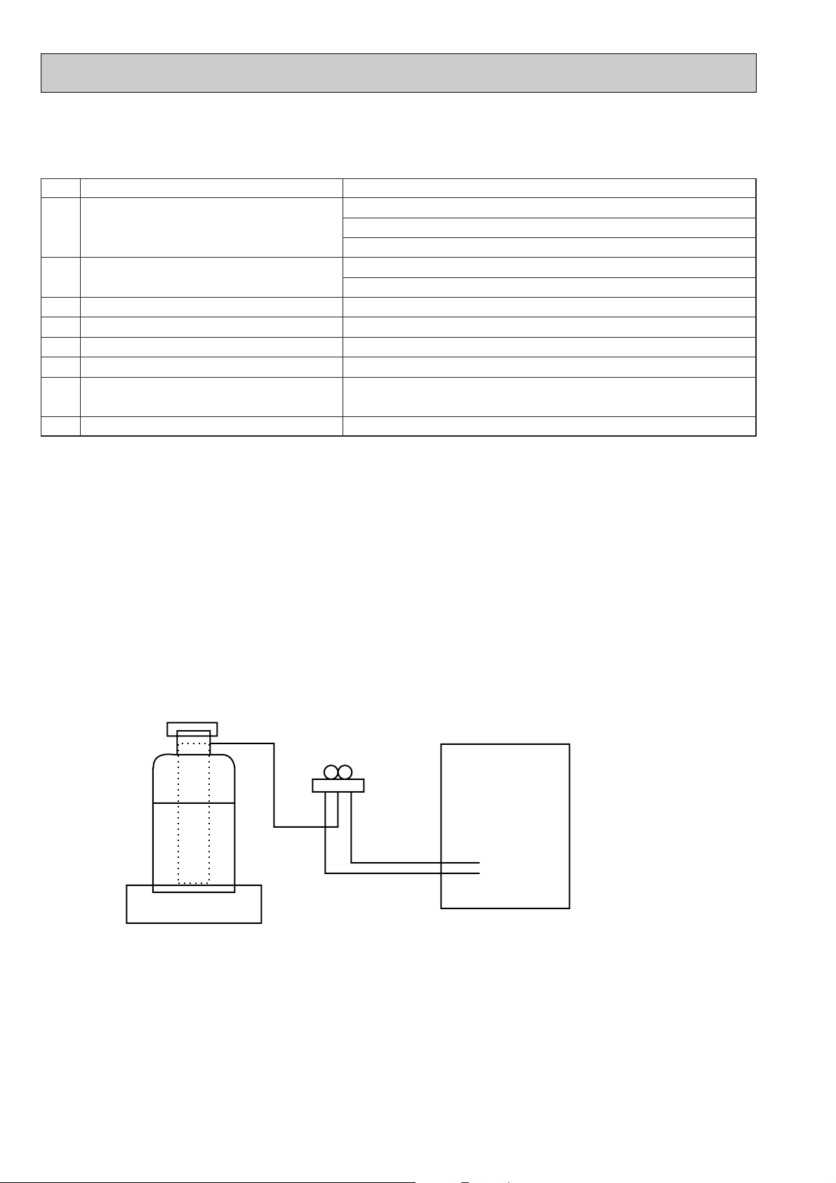
[1] Service tools
Gravimeter
Unit
Use the below service tools as exclusive tools for R407C refrigerant.
No. Tool name Specifications
1 Gauge manifold ·Only for R407C.
·Use the existing fitting SPECIFICATIONS. (UNF7/16)
·Use high-tension side pressure of 3.43MPa·G or over.
2 Charge hose ·Only for R407C.
·Use pressure performance of 5.10MPa·G or over.
3 Electronic scale
4 Gas leak detector ·Use the detector for R134a or R407C.
5 Adapter for reverse flow check. ·Attach on vacuum pump.
6 Refrigerant charge base.
7 Refrigerant cylinder. ·For R407C ·Top of cylinder (Brown)
·Cylinder with syphon
8 Refrigerant recovery equipment.
[2] Notice on repair service
·After recovering the all refrigerant in the unit, proceed to working.
·Do not release refrigerant in the air.
·After completing the repair service, recharge the cycle with the specified amount of
liquid refrigerant.
[3] Refrigerant recharging
(1) Refrigerant recharging process
1Direct charging from the cylinder.
·R407C cylinder are available on the market has a syphon pipe.
·Leave the syphon pipe cylinder standing and recharge it.
(By liquid refrigerant)
(2) Recharge in refrigerant leakage case
·After recovering the all refrigerant in the unit, proceed to working.
·Do not release the refrigerant in the air.
·After completing the repair service, recharge the cycle with the specified amount of
liquid refrigerant.
4
Page 5
2
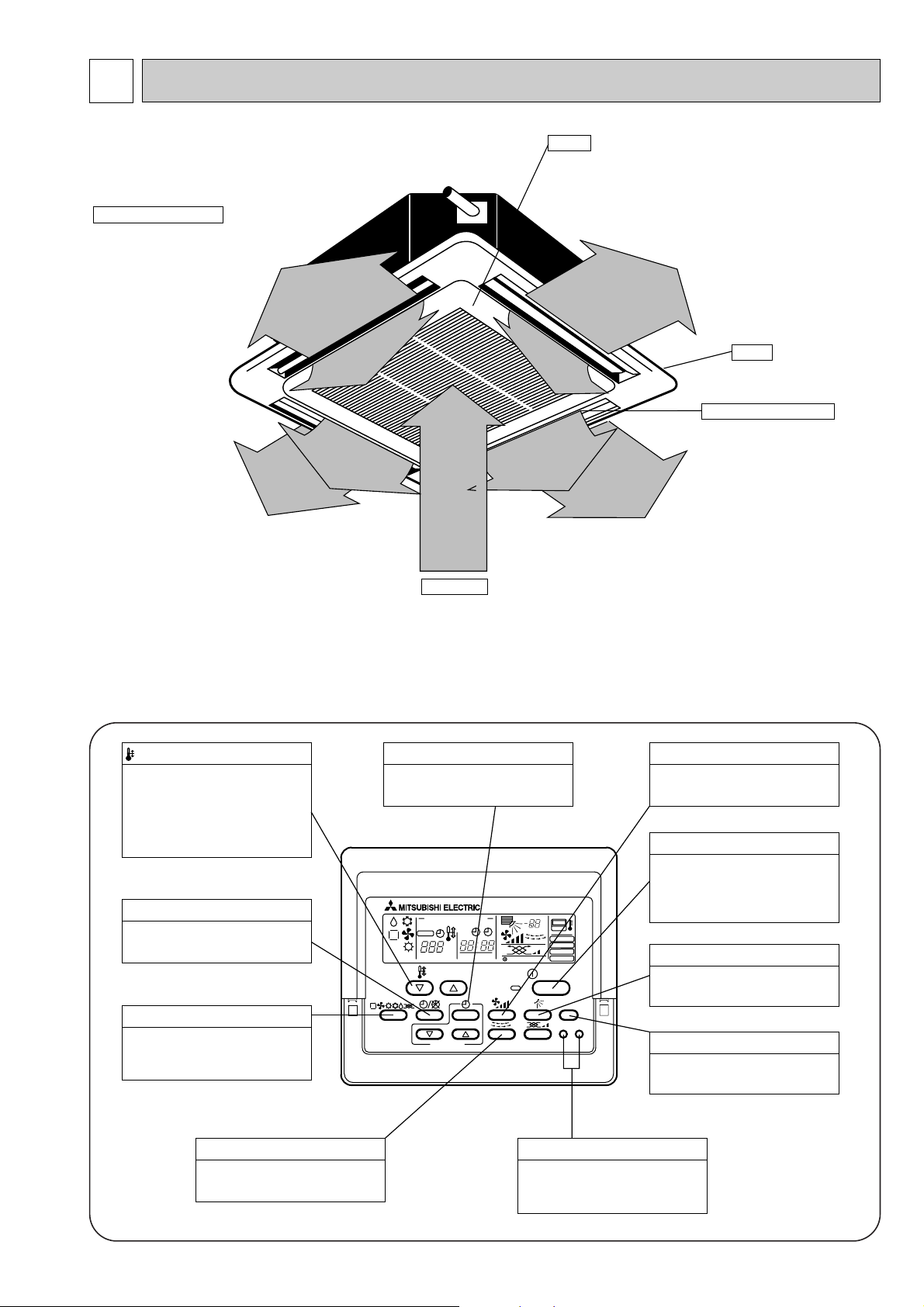
Auto Air Swing Vane
Disperses airflow up and
down and adjusts the angle
of airflow direction.
Grille
Filters
Remove dust and pollutants
from return air
Horizontal Air Outlet
Sets airflow horizontal automatically
during cooling or dehumidifying.
Air Intake
Returns air from room.
PAR-20MAA
ON/OFF
CENTRALLY CONTROLLED
ERROR CODE
CLOCK
ON OFF
˚C
CHECK
CHECK MODE
FILTER
TEST RUN
FUNCTION
˚C
1Hr.
NOT AVAILABLE
STAND BY
DEFROST
FILTER
CHECK TEST
TEMP.
TIMER SET
Press this button to switch the cooler,
electronic dry (dehumidify), automatic
and heater modes.
OPERATION SWITCH button
This sets the room temperature. The
temperature setting can be performed
in 1: units
Setting range
Cooler 19: to 30:
Heater 17: to 28:
TEMP. ADJUSTMENT button
This switches between continuous
operation and the timer operation.
TIMER button
This switches between the operation
and stop modes each time it is pressed.
The lamp on this button lights during
operation.
ON/OFF button
Only press this button to perform an
inspection check or test operation.
Do not use it for normal operation.
CHECK-TEST RUN button
This switch the horizontal fan motion
ON and OFF.
(Not available for this model.)
LOUVER button
This adjusts the vertical angle of the
ventilation.
AIR DIRECTION button
This resets the filter service indication
display
FILTER button
This sets the current time, start time
and stop time.
TIME SETTING button
This sets the ventilation fan speed.
AIR SPEED button
PART NAMES AND FUNCTIONS
● Indoor (Main) Unit
● Remote controller
● Operation buttons
[PAR-20MAA]
● Once the controls are set, the same operation mode can
be repeated by simply pressing the ON/OFF button.
5
Page 6
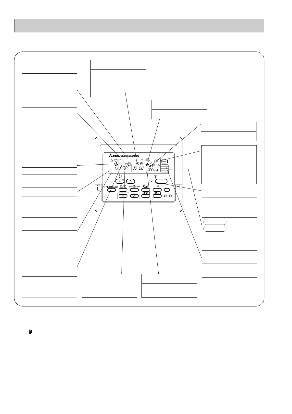
● Display
PAR-20MAA
ON/OFF
CENTRALLY CONTROLLED
ERROR CODE
CLOCK
ON OFF
˚C
CHECK
CHECK MODE
FILTER
TEST RUN
FUNCTION
˚C
1Hr.
NOT AVAILABLE
STAND BY
DEFROST
FILTER
CHECK TEST
TEMP.
TIMER SET
CENTRALLY
CONTROLLED display
This indicates when the unit is con-
trolled by optional features such as
central control type remote controller.
TIMER display
This indicates when the continuous
operation and time operation modes
are set.
It also display the time for the timer
operation at the same time as when
it is set.
OPERATION MODE display
This indicates the operation mode.
STANDBY display
The [STANDBY] symbol is only
displayed from the time the heating
operation starts unit the heated air
begins to blow.
DEFROST display
This indicates when the defrost oper-
ation is performed.
CLOCK display
The current time , start time and stop
time can be displayed in ten second
intervals by pressing the time switch
button. The start time or stop time is
always displayed during the timer
operation.
In this display example on the bottom left, a condition where all display lamps light is shown for explanation purposes although this differs
from actual operation.
AIR DIRECTION display
This displays the air direction.
AIR SPEED display
The selected fan speed is displayed.
ROOM TEMPERATURE display
The temperature of the suction air is
displayed during operation. The display range is 8°C to 39°C. The display flashes 8°C when the actual
temperature is less than 8°C and
flashes 39°C when the actual temperature is greater than 39°C.
Operation lamp
This lamp lights during operation,
goes off when the unit stops and
flashes when a malfunction occurs.
CHECK MODE
TEST RUN
This display lights in the check mode
or when a test operation is performed.
display
FILTER display
CHECK display
This indicates when a malfunction
has occurred in the unit which should
be checked.
SET TEMPERATURE display
This displays the selected setting
temperature.
Caution
● Only the Power display lights when the unit is stopped and power supplied to the unit.
● When the central control remote control unit, which is sold separately, is used the ON-OFF button, operation switch button
and TEMP. adjustment button do not operate.
● “NOT AVAILABLE” is displayed when the Air speed button are pressed.This indicates that this room unit is not equipped
with the fan direction adjustment function and the louver function.
● When power is turned ON for the first time, it is normal that “H0” is displayed on the room temperature indication (For max.
2minutes). Please wait until this “H0” indication disappear then start the operation.
POWER display
This lamp lights when electricity is
supplied to the unit.
This lamp lights when the filter need
to be cleaned.
6
Page 7
3
Item
kW
kW
kW
kW
A
A
—
mm
mm
mm
—
—
k/min
Pa
kW
—
—
[mm(in.)
[mm(in.)
[mm
dB
kg
Cooling capacity
Power
Heat exchanger
Insulator
Air filter
Fan ✕ No
Air flow W3
Pipe
dimensions
Cond. drain pipe size
Noise level W3
Product weight
Exterior
(munsell symbol)
Fan motor
output
External
static pressure
Liquid
side
Gas
side
Heating capacity
F
a
n
Dimensions
Height
Width
Depth
Electric characteristic
Input
Cooling
Heating
Cooling
Heating
Current
PLFY-P32VKM-A.UK PLFY-P40VKM-A.UK PLFY-P50VKM-A.UK PLFY-P63VKM-A.UK
3.6
4.0
0.13
0.13
0.60
0.60
4.5
5.0
0.13
0.13
0.60
0.60
5.6
6.3
0.14
0.14
0.64
0.64
7.1
8.0
0.15
0.15
0.68
0.68
16-15-14-13
15-14.5-14-13
12.7(1/2")
6.35(1/4")
35-34-32.5-31
17-16-15-14
Unit : Galvanized sheets · Standard grills : ABS resin acrylic coating Munsell<0.70Y 8.59/0.97>
298<30>
660<760>
660<760>
Cross fin
Turbo fan ✕ 1
0
0.030
Polyethylene sheet
PP honey comb
O.D.32 (PVC pipe VP-25 connectable)
15.88(5/8")
9.52(3/8")
37-35.5-34-32
39-38-36.5-35
19<3.7>
20<3.7>
Single phase , 220-230-240V , 50Hz
[,V,Hz
SPECIFICATION
3-1. Specification
Note 1. Rating conditions(JIS B 8616)
Note 2. The number indicated in < > is just for the grill.
W 3. Air flow and the noise level are indicated as High-Middium 1-Middium 2-Low.
Cooling : Indoor : D.B. 27°C W.B. 19.0°C
Heating : Indoor : D.B. 20°C
outdoor : D.B. 35°C
outdoor : D.B. 7°C W.B. 6°C
7
Page 8
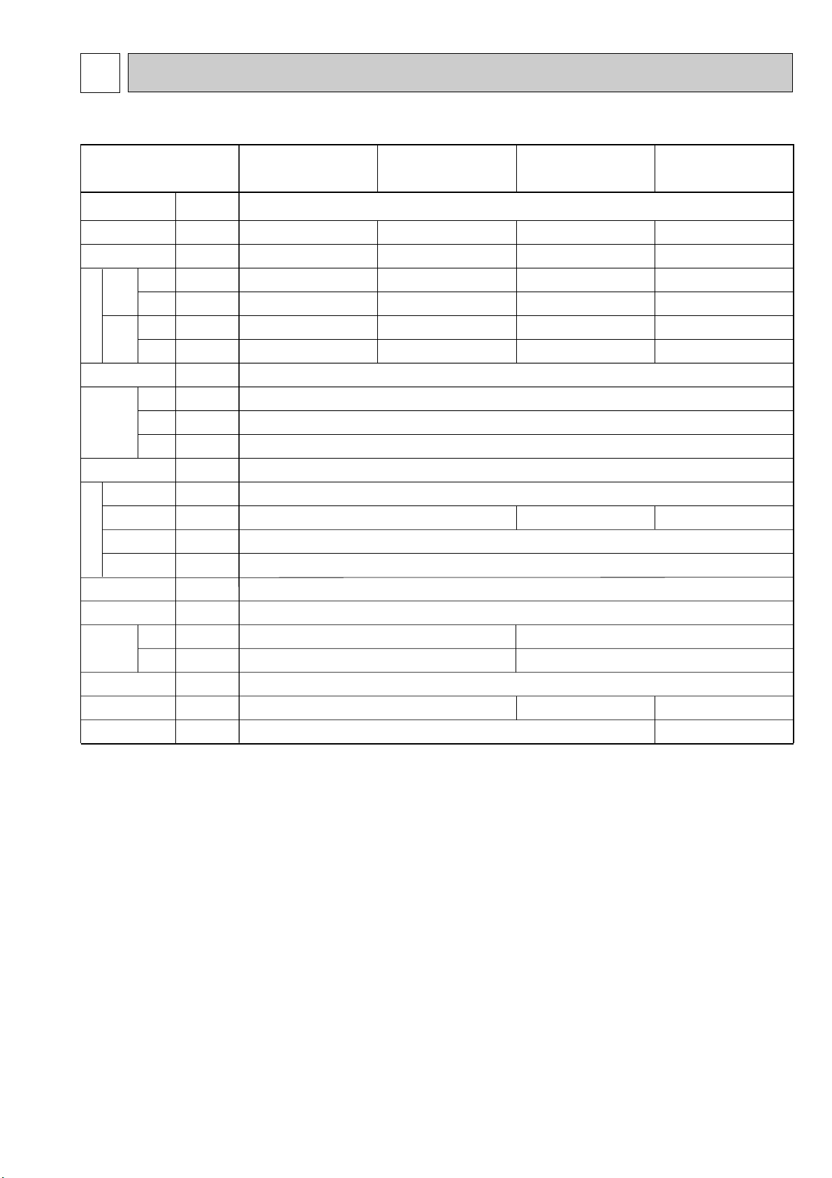
3-2. Electrical parts specifications
Model
Parts
Symbol
name
PLFY-P32VKM-A.UK PLFY-P40VKM-A.UK PLFY-P50VKM-A.UK PLFY-P63VKM-A.UK
Room temperature
thermistor
Liquid pipe thermistor
Gas pipe thermistor TH23 Resistance 0:/15k', 10:/9.6k', 20:/6.3k', 25:/5.2k', 30:/4.3k', 40:/3.0k'
Fuse FUSE 250V 6.3A
(Indoor controller board)
Fan motor
(with Inner-thermostat)
Fan motor capacitor C
Vane motor MV
(with limit switch)
TH21 Resistance 0:/15k
TH22 Resistance 0:/15k', 10:/9.6k', 20:/6.3k', 25:/5.2k', 30:/4.3k', 40:/3.0k'
MF
Inner-thermostat
', 10:/9.6k', 20:/6.3k', 25:/5.2k', 30:/4.3k', 40:/3.0k'
6-pole OUTPUT 30W
PA1-V30F
OFF 125:±5:
ON 85:±20:
2.5+ x 400V
MC8 200V-240V
2.5/2W 5/6R.P.M
Drain-up mechanism DP
Drain sensor DS
Linear expansion valve LEV
Electric heater H2 240V 28.8W
(Condensation proof)
Power supply terminal
block
Transmission terminal
block
MA remote controller
terminal block
TB15 (1,2) 250V 10A
Heater resistance 0:/6k
TB2 (L,N,;) 330V 30A
TB5 (M1,M2,S) 250V 20A
', 10:/3.9k', 20:/2.6k', 25:/2.2k', 30:/1.8k', 40:/1.3k'
INPUT 8/7.5W 24R/Hr
DC12V Stepping motor drive port
dimension 3.2
PJV-1002
(0~2000pulse)
'
EDM-402ME
8
Page 9

4
Ceiling hole
Suspension bolt pitch
Suspension bolt M10 or
Air intake hole
Air outlet hole
Air intake grille
690~710 25~3525~35
640
660
466
460
66 35
760
117 117
117
435
13554
117
Ceiling hole
Suspension bolt pitch
Suspension bolt lower edge
Air outlet hole
Air outlet hole
690~710
25~3525~35
65~80
760
460
466
6635
115
243
253
29830
54
+3
- 2
507
660
54
53
Terminal block for power supply
Terminal block for
MA remote controller
Terminal block for
transmission
Drain hole
Drain hole ID32
VP-25 connection
W3/8
Feeding hole
(Drain pump)
Leave space of 10~15mm between the
top surface of the unit and the ceiling slab.
Ceiling surface
4-Auto vanes
Intake grille opening
/closing side
Vane motor
Decorative panel
Control wire entry
Refrigerant piping side
electric wire entry side
Power line entry
41 25
Liquid pipe
Gas pipe
Optional
high-efficiency filter
+3
-2
NOTE 1.The electrical parts box may be removed during servic ing. When connecting the power line and the control
wire, provide enough length to the electric wires.
NOTE 2.When installing the optional high-efficiency filter, the
space inside the ceiling should be 440mm or more.
Also, when installing the optional the multi-functional
casement (fresh air intake casement), the dimension
between the transom and ceiling shall be more than
440mm. (The optional high-efficiency filter can also
be installed.)
OUTLINES AND DIMENSIONS
PLFY-P32VKM-A.UK
PLFY-P40VKM-A.UK
PLFY-P50VKM-A.UK
PLFY-P63VKM-A.UK
Models
PLFY-P32VKM-A.UK
PLFY-P40VKM-A.UK
PLFY-P50VKM-A.UK
PLFY-P63VKM-A.UK
1
Refrigerant pipe
(6.35mmdia)
flared connection
1/4F
Refrigerant pipe
(9.52mmdia)
flared connection
3/8F
Unit : mm
2
Refrigerant pipe
(12.7mmdia)
flared connection
1/2F
Refrigerant pipe
(15.88mmdia)
flared connection
5/8F
9
Page 10

5
PLFY-P32VKM-A.UK, PLFY-P40VKM-A.UK
PLFY-P50VKM-A.UK, PLFY-P63VKM-A.UK
WIRING DIAGRAM
10
Page 11

REFRIGERANT SYSTEM DIAGRAM6
Strainer (#50mesh)
Strainer (#100mesh)
Strainer (#100mesh)
Heat exchanger
Room temperature thermistor TH21
Gas pipe thermistor TH23
Liquid pipe thermistor TH22
Linear expansion valve
Gas pipe
Liquid pipe
Flare connection
PLFY-P32VKM-A.UK
PLFY-P40VKM-A.UK
PLFY-P50VKM-A.UK
PLFY-P63VKM-A.UK
Item
Gas pipe
Liquid pipe
Capacity
PLFY-P32VKM-A.UK
PLFY-P40VKM-A.UK
PLFY-P50VKM-A.UK
PLFY-P63VKM-A.UK
{12.7(1/2’’) {15.88(5/8’’)
{6.35(1/4’’) {9.52(3/8’’)
11
Page 12

7
1
1
2
2
3
3
Red
White
Black
Relay connector
Protector
M
4
6
2
3
5
1
Blue
Brown
Yellow
Orange
Red
White
1
2
Gray
Gray
1
2
3
TROUBLE SHOOTING
7-1. How to check the parts PLFY-P32/P40/P50/P63VKM-A.UK
Parts name Check points
Room temperature
thermistor
Liquid pipe thermistor
Gas pipe thermistor
(TH21)
(TH22)
(TH23)
Disconnect the connector, then measure the resistance using a tester.
(Surrounding temperature 10°C~30°C)
Normal
4.3k'~9.6k'
Abnormal
Open or short
(Refer to the next page for a detail..)
Vane motor
Fan motor
Linear expansion
valve
Drain-up
mechanism
Measure the resistance between the terminals using a tester.
(Surrounding temperature 20;~30;)
Normal
Approx.14k'
Measure the resistance between the terminals using a tester.
Motor terminal
or
Relay connector
Red-Black
White-Black
Disconnect the connector then measure the resistance valve using a tester.
(Refer to the next page for a detail.)
(1)-(5)
White-Red
(2)-(6)
Yellow-
Abnormal
Open or short
PLFY- • VKM-A.UK
P32,P40,P50,P63
Normal
(3)-(5)
Blown
Orange-Red
Normal
136.2'
197.5'
(4)-(6)
Blue-Brown
Abnormal
Open or short
Abnormal
Open or short
150' ±10%
Measure the resistance between the terminals using a tester.(Surrounding temperature : 20;~30;)
Normal
327'
Abnormal
Open or short
Drain sensor
Measure the resistance after 3 minutes have passed since the power supply was intercepted.
(Surrounding temperature : 0; ~ 60;)
Normal
0.6k'~6.0k'
Abnormal
Open or short
12
(Refer to the next page for a detail..)
Page 13

<Thermistor Characteristic graph>
-200 20406080
< Thermistor for drain sensor >
Temperature (:)
0
1
2
3
4
5
6
7
8
9
10
Resistance (K")
Thermistor for
lower temperature
Room temperature thermistor(TH21)
Liquid pipe thermistor(TH22)
Gas pipe thermistor(TH23)
Thermistor R0=15k' ±3%
Fixed number of B=3480k' ±2%
Rt=15exp { 3480( ) }
1
273+t
1
273
0: 15k'
10: 9.6k'
20: 6.3k'
25: 5.2k'
30: 4.3k'
40: 3.0k'
Thermistor for
drain sensor
Thermistor R0=6.0k' ±5%
Fixed number of B=3390k' ±2%
< Thermistor for lower temperature >
50
40
30
20
Resistance (K")
10
0
-20 -10 0 10 20 30 40 50
Temperature (:)
Rt=6exp { 3390( ) }
0: 6.0k'
10: 3.9k'
20: 2.6k'
25: 2.2k'
30: 1.8k'
40: 1.3k'
Linear expansion valve
① Operation summary of the linear expansion valve.
• Linear expansion valve open/close through stepping motor after receiving the pulse signal from the indoor controller board.
• Valve position can be changed in proportion to the number of pulse signal.
<Connection between the indoor controller board and the linear expansion valve>
Note : Since the number of the connector at the controller board side and the relay connector are different, follow the color of
the lead wire.
1
273+t
Linear expansion valve
4
M
6
2
5
White
1
Red
3
Orange
Blue
Brown
Yellow
1
273
[4
[3
[2
[1
Relay connector
5
1
3
4
6
13
Brown
Red
Blue
Orange
Yellow
White
Connector(CN60)
Controller board
DC12V
62
5
4
3
2
1
Drive circuit
[4
[3
[2
[1
Page 14

<Output pulse signal and the valve operation>
D
A
E
B
C
Open
Extra tightning (80~100 pulse)
Pulse number
2000 pulse
Opening a valve
all the way
Close
Valve position (capacity)
6
5
4
3
2
1
LED1T
Thermistor
(Liquid pipe)
Linear
expansion
valve
150
'
10%.
Output
(Phase)
{1
{2
{3
{4
Linear expansion valve operation
➁
1
ON
ON
OFF
OFF
2
OFF
ON
ON
OFF
Output
3
OFF
OFF
ON
ON
4
ON
OFF
OFF
ON
Closing a valve : 1 → 2 → 3 → 4 → 1
Opening a valve : 4 → 3 → 2 → 1 → 4
The output pulse shifts in above order.
❈ 1. When linear expansion valve operation stops, all output phase
become OFF.
2. At phase interruption or when phase does not shift in order,
motor does not rotate smoothly and motor will locks and vibrates.
❈ When the switch is turned on, 2200 pulse closing valve signal
will be send till it goes to
A point in order to define the valve posi-
tion.
When the valve move smoothly, there is no noise or vibration
occurring from the linear expansion valve : however, when the
pulse number moves from E to A or when the valve is locked,
more noise can be heard than normal situation.
❈ Noise can be detected by placing the ear against the screw dri-
ver handle while putting the screw driver to the linear expansion
valve.
Trouble shooting
➂
Symptom
Operation circuit failure of the micro
processor.
Linear expansion
valve mechanism is
locked.
Short or breakage of
the motor coil of the
linear expansion
valve.
Valve doesn't close
completely (thermistor leaking).
Wrong connection of
the connector or
contact failure.
Check points
Disconnect the connector on the controller board, then connect LED for checking.
Pulse signal will be sent out for 10 seconds as soon as the
main switch is turn on. If there is LED with lights on or lights
off, it means the operation circuit is abnormal.
Motor will idle and make ticking noise when motor is operated
while the linear expansion valve is locked. This ticking sound
is the sign of the abnormality.
Measure the resistance between the each coil (red-white,
red-orange, brown-yellow, brown-blue) using a tester. It is
normal if the resistance is in the range of
To check the linear expansion valve, operate the indoor unit
in fan mode and at the same time operate other indoor units
in cooling mode, then check the pipe temperature <liquid
controller, it means the valve is not closed all the way. It is
not necessary to exchange the linear expansion valve, if the
leakage is small and not making any trouble.
Check the color of lead wire and missing terminal of the connector.
pipe temperature> of the indoor unit by the
outdoor multi controller board operation
monitor. During fan operation, linear
expansion valve is closed completely and if
there are some leaking, detecting temperature of the thermistor will go lower. If the
detected temperature is much lower than
the temperature indicated in the remote
14
Countermeasures
Exchange the indoor controller board at drive circuit
failure.
Exchange the linear
expansion vale.
Exchange the linear
expansion valve.
If large amount of thermistor is leaked, exchange the
linear expansion valve.
Disconnect the connector
at the controller board,
then check the continuity.
Page 15

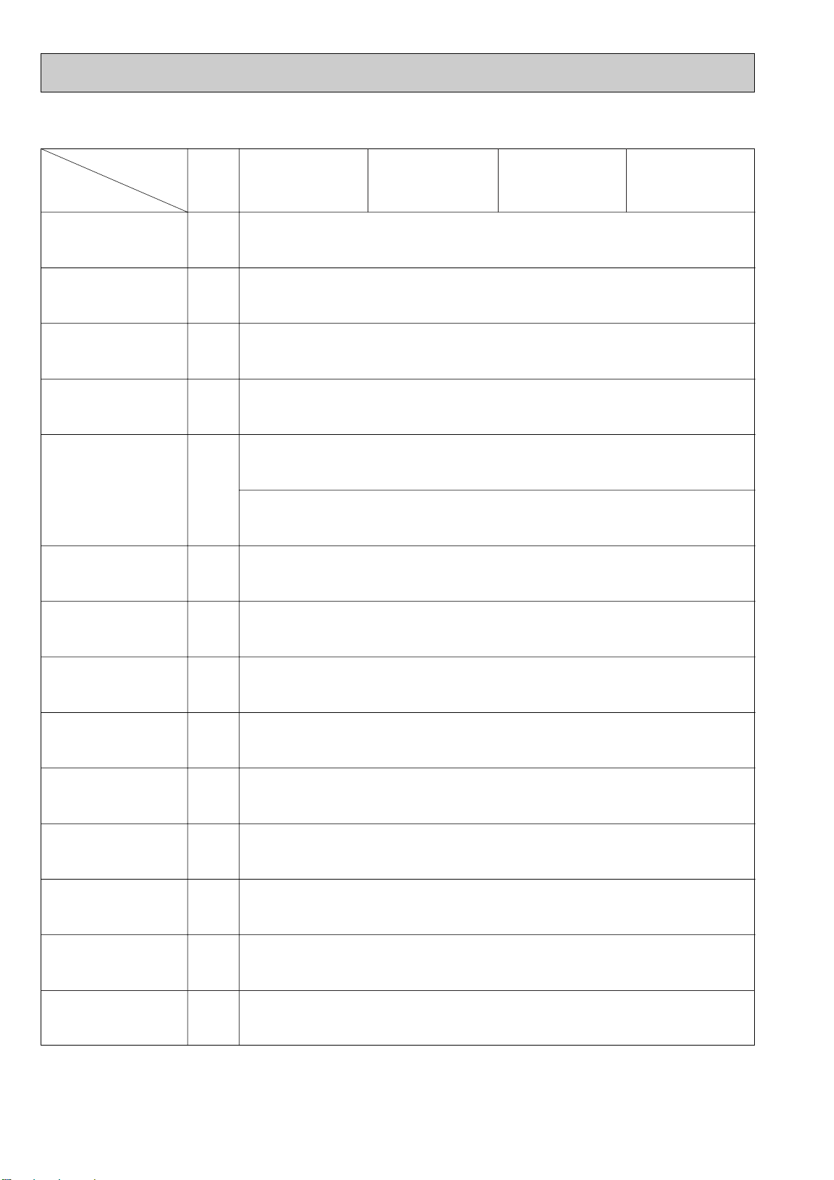
7-2. FUNCTION OF DIP SWITCH
Switch Function Remarks
<At delivery>
ON
OFF
123456789
10
Address board
Operation by switch
ON OFF
Note :
w1
Fan operation at Heating
mode.
w2
Heater thermo ON is
operating.
w3
SW 1-7=OFF, SW 1-8=ON
→ Setting air flow.
SW 1-7=ON, SW 1-8=ON
→ Indoor fan stop.
Pole
Built-in remote controller
Provided
2,500hr
Effective
Thermostat ON signal indication
Always operated while the heat in ON w1
Low w3
Setting air flow w3
Effective
Effective
Filter clogging detection
Filter cleaning
Fresh air intake
Remote indication switching
Humidifier control
Air flow set in case of
Heat thermostat OFF
Auto restart function
Power ON/OFF
Indoor unit
Not provided
100hr
Not effective
Fan output indication
Operated depends on the condition w2
Extra low w3
Depends on SW1-7
Not effective
Not effective
Cooling only
Available
Available
Available
Second setting
Horizontal angle
Effective
Not effective
9(5)degrees
15degrees
Heat pump / Cooling only
Louver
Vane
Vane swing function
Vane horizontal angle
Vane cooling limit angle setting w4
Heat 4degrees up
Superheat setting temperature
w5
Sub cool setting temperature
Heat pump
Not available
Not available
Not available
First setting
Down B, C
Not effective
Effective
6(2)degrees
10degrees
1
2
3
4
5
6
7
8
9
10
1
2
3
4
5
6
7
8
9
10
SW1
Mode
Selection
SW2
Capacity
code
setting
1~6
1~5
SW3
Function
Selection
SW4
Unit
Selection
Indoor linear expansion
valve opening
Thermistor <intake temperature
detection> position
<At delivery>
ON
OFF
123456789
10
Indoor controller board
Note :
w4
At cooling mode, each
angle can be used only
1 hour.
w5
The numerical valve in
the parentheses shows
the case which the R22
outdoor unit is connected.
<At delivery>
Indoor controller board
<At delivery>
Set while the unit is off.
Set while the unit is off.
PLFY-P32VKM-A.UK
PLFY-P40VKM-A.UK
ON
OFF
123456789
10
PLFY-P50VKM-A.UK
PLFY-P63VKM-A.UK
Set while the unit is off.
Set for each capacity.
Indoor controller board
ON
OFF
12345
ON
OFF
MODELS
PLFY-P32
VKM-A.UK
PLFY-P50
VKM-A.UK
PLFY-P63
VKM-A.UK
PLFY-P40
VKM-A.UK
SW 2 MODELS SW 2
123456
ON
OFF
123456
ON
OFF
123456
ON
OFF
123456
ON
OFF
12345
15
Page 16

0
5
9
4
8
3
7
2
6
1
0
5
9
4
8
3
7
2
6
1
0
5
9
4
8
3
7
2
6
1
0
5
9
4
8
3
7
2
6
1
0
8
F
7
E
6
D
5
C
4
B
3
A
2
9
1
0
8
F
7
E
6
D
5
C
4
B
3
A
2
9
1
220V 240V
Switch
SWA
Ceiling
height
selector
SWB
Discharge
outlet
number
selector
SWC
Option
selector
Rotary switchRotary switch
SW14
Connection
No.
setting
SW5
Voltage
Selection
SW11
1st digit
address
setting
SW12
2nd digit
address
setting
Pole
(High ceiling)
(Standard)
(Silent)
3
2
1
(Not used)
(3
direction)
(4 direction)
2
3
4
Option
Standard
Option
Standard
1~3
3
2
2
Operation by switch
✽ Ceiling height can be changed depends on
SWB setting.
Address setting should be done when M-NET
Remote controller is being used.
When attach the optional high performance
filter elements (multi function casement) to
the unit, be sure to attach it to the option
side in order to prevent the airflow reducing.
This is the switch to be used when the indoor
unit is operated with R2 series outdoor unit
as a set.
If the unit is used at the 230V or 240V area,
set the voltage to 240V.
If the unit is used at the 220V, set the voltage
to 220V.
Remarks
<At delivery>
Address board
<At delivery>
Address board
<At delivery>
Address board
Address can be set while the
unit is stopped.
Address board
<At delivery>
Address board
<At delivery>
Address board
3
2
1
2
3
4
SW1210SW11
1
SW12 SW11
SW14
SW14
<At delivery>
220V 240V
SWB
4 direction
3 direction
4
3
2.7m
2.4m
2.7m
3.0m
3.0m
3.3m
SWA
1
Silent Standard
High
ceiling
23
16
Page 17

8
DISASSEMBLY PROCEDURE
INDOOR UNIT
PLFY-P63VKM-A.UK
OPERATING PROCEDURE PHOTOS&ILLUSTRATIONS
1. Removing the air intake grille
(1) Press the button.
(2) Open the intake grille 90°.
(3) Remove the chip.
(4) Slide the shaft in the hinge to the left and remove the
intake grille.
2. Removing the fan guard
(1) Open the intake grille.
(2) Remove the 4 screws of the fan guard.
PUSH
Figure 1
PUSH button
Photo 1
Fan guard
Be careful on removing heavy parts.
Shaft
Intake grille
Fan guard screws
3. Removing the electrical parts box
(1) Remove the fan guard.
(2) Disconnect the lead wire of the vane motor from the clamp,
and disconnect the red connector (10P).
(3) Remove 2 of 4 screws from the electrical parts cover.
(4) Remove the electrical parts cover.
(5) Disconnect the following connectors from the box.
Red (3P) for the fan motor
White (2P) for the indoor coil thermistor
Blue (2P) for the drain pump
White (3P) for the drain sensor
(6) Disconnect the green anti-falling wire of the electrical parts
box.
(7) Remove 3 of 4 screws from the electrical parts box, and
loosen the other screw.
(8) Pull out the electrical parts box.
Electrical parts inside the box
Terminal block
Indoor fan capacitor
Room temperature thermistor
Indoor controller board
4. Removing the fan motor
(1) Remove the fan guard.
(2) Remove the turbo-fan nut and radiator aluminum cap.
(3) Pull out the turbo fan.
(4) Disconnect the connector of the fan motor lead wire.
(5) Remove the 3nuts of fan motor.
Photo 2
Photo 3
Electrical box
Room
temperature
thermistor
Radiator
aluminum cap
Photo 4
Connector
Screws
Screws
Fan motorConnector
Lead wire for
vane motor
Nut
ConnectorTerminal blockAnti-falling wire
Box
cover
Clamp
Indoor
controller
board
Capacitor
17
nut
Page 18

OPERATING PROCEDURE PHOTOS&ILLUSTRATIONS
5. Removing the room temperature thermistor
(1) Remove the fan guard.
(2) Remove the electrical box cover
(3) Remove the holder and the room temperature thermistor
by pulling the catch.
(4) Disconnect the red connector, CN20, on the indoor con-
troller board.
6. Removing the pipe temperature detection / liquid thermistor
and the pipe temperature detection / gas thermistor
(1) Remove the fan guard.
(2) Remove the electrical box cover.
(3) Remove the electrical box.
(4) Remove the turbo fan.
(5) Remove the screw of the service panel.
(6) Remove the service panel.
(7) Remove the pipe temperature detection / liquid thermistor
and the pipe temperature detection / gas thermistor which
is inserted into the holder installed to the thin copper pipe.
(8) Disconnect the each 2-pin white(liquid) and black(gas)
connector.
Photo 5
Room
temperature
thermistor
Photo 6
Pipe temperature
detection / gas
thermistor
Indoor controller board
Pipe temperature
detection / liquid
thermistor
Mounting hole
7. Removing the panel
(1) Open the intake grille.
(2) Disconnect the connector the vane motor.
(3) Remove 4 screws of the panel.
(4) Pulling the temporary hanging hook, remove the panel.
8. Removing the drain pan
(1) Remove the panel.
(2) Remove the fan guard.
(3) Remove the rubber bushing.
(4) Drain the remaining water in the drain pan.
(5) Remove the electrical box cover.
(6) Remove the electrical box.
(7) Remove the screw of the V.A. cover, and remove the V.A.
cover.
(8) Remove each screw of the corner supports 1,2, and 3,
and remove the corner supports 1,2 and 3.
(9) Pull out the drain pan.
wPull the left and right of the pan gradually.
Be careful not to crack or damage the pan.
Photo 7
screws
Panel
Photo 8
Corner
support 2
VAcover
Temporary hanging hook
Fan guard
Rubber
bush
Corner
support 3
screws
Temporary hanging hook
Screws
Corner
support 1
18
Page 19

OPERATING PROCEDURE PHOTOS&ILLUSTRATIONS
9. Removing the drain pump and drain sensor
(1) Remove the panel.
(2) Remove the fan guard.
(3) Remove the electrical parts cover.
(4) Remove the electrical parts box.
(5) Remove the drain pan.
(6) Remove 4 screws of the drain pump.
(7) Pulling the clip of the drain hose, pull out the drain hose
from the drain pump.
(8) Remove the drain sensor and the holder.
(9) Pull out the drain pump.
10. Removing the heat exchanger
(1) Remove the panel.
(2) Remove the fan guard.
(3) Remove the electrical parts cover.
(4) Remove the electrical parts box.
(5) Remove the drain pan.
(6) Remove the turbo fan.
(7) Remove the screw of the coil support A.
(8) Remove 2 screws of the coil support B.
(9) Remove 2 screws of the coil.
(10) Remove 4 screws of the piping cover of the outer wall,
and pull out the piping cover.
Photo 9
Clip
Screws
Photo 10
Coil support A
Drain hose
Drain pump
Heat exchanger
Drain sensor
holder
Photo 11
Piping
cover
Coil support B
Coil screws
Screws of piping
cover
19
Page 20

9
1
2
3
4
5
6
1
1
1
2
1
1 R.B
AIR OUTLET GRILLE
AIR FILTER
INTAKE GRILLE
HINGE
GRILLE HANGER
MA-REMOTE CONTROLLER
65WRC5
<PAR-20MAA>
No. Part No. Part Name Specification
Q'ty/set
Price
Unit
Amount
Remarks
(Drawing No.)
Wiring
Diagram
Symbol
Recom-
mended
Q'ty
PLFY-P32/P40/
P50/P63
VKM-A.UK
S70 29H 003
S70 29H 500
S70 29H 691
S70 29H 061
S70 29H 098
S70 030 713
PAR-20MAA
ON/OFF
CENTRALLY CONTROLLED
ERROR CODE
CLOCK
ON OFF
˚C
CHECK
CHECK MODE
FILTER
TEST RUN
FUNCTION
˚C
1Hr.
NOT AVAILABLE
STAND BY
DEFROST
FILTER
CHECK TEST
TEMP.
TIMER SET
PARTS LIST
PANEL PARTS
PLFY-P32VKM-A.UK
PLFY-P40VKM-A.UK
PLFY-P50VKM-A.UK
PLFY-P63VKM-A.UK
20
6
Page 21

PANEL PARTS
PLFY-P32VKM-A.UK
PLFY-P40VKM-A.UK
PLFY-P50VKM-A.UK
PLFY-P63VKM-A.UK
2
1
14
3
1
4
1
4
8
5
7
Part number that is circled is not shown in the figure.
No. Part No. Part Name
1
S70 29H 002
2
S70 31H 063
3
S70 29H 223
4
S70 29H 063
5
S70 29H 041
6
S70 29H 040
7
S70 29H 056
8
S70 29H 085
9
S70 29H 049
AUTO VANE
SPRING JOINT 2
VANE MOTOR
SPRING JOINT 1
GRILLE GEAR LEFT
GRILLE GEAR RIGHT
PUSH BUTTON
AIR GUIDE
LID (UP)
Specification
21
Q'ty/set
PLFY-P32/P40
/P50/P63
VKM-A.UK
4
1
1
1
1
1
1
1
1
6
Remarks
(Drawing No.)
<3/SET>
Wiring
Diagram
Symbol
MV
Recom-
mended
Q'ty
Unit
Price
Amount
Page 22

FUNCTIONAL PARTS
PLFY-P32VKM-A.UK
PLFY-P40VKM-A.UK
PLFY-P50VKM-A.UK
PLFY-P63VKM-A.UK
1
2
4
38
3
4
5
6
7
8
9
10
11
12
3
37
36
35
34
33
32
31
30
29
28
13
14
15
16
17
18
20
22
21
27
26
11
25
24
2219
23
Page 23

1
2
3
4
5
6
7
8
9
10
11
12
13
14
15
16
17
18
19
20
21
22
23
24
25
26
27
28
29
30
31
32
33
34
35
36
37
38
3
1
2
2
1
1
1
1
1
1
2
1
1
1
1
1
1
1
1
1
1
1
1
1
1
1
1
1
1
1
1
1
1
1
1
1
1
1
3
1
2
2
1
1
1
1
1
1
2
1
1
1
1
1
1
1
1
1
1
1
1
1
1
1
1
1
1
1
1
1
1
1
1
1
1
1
3
1
2
2
1
1
1
1
1
1
2
1
1
1
1
1
1
1
1
1
1
1
1
1
1
1
1
1
1
1
1
1
1
1
1
1
1
1
PLFY- · VKM-A.UK
3
1
2
2
1
1
1
1
1
1
2
1
1
1
1
1
1
1
1
1
1
1
1
1
1
1
1
1
1
1
1
1
1
1
1
1
1
1
MF
C
TB2
I.B
I.B
I.B
I.B
FUSE
A.B
P.B
TH21
TB15
TB5
DS
LEV
DP
TH23
TH22
(PART OF GRILLE)
(PART OF BOARD)
MOTOR MOUNT
FAN MOTOR
LEG
LEG
NUT/WASHER/CAP
HEAT EXCHANGER
HEAT EXCHANGER
HEAT EXCHANGER
DRAIN PAN
CORNER SUPPORT(2)
ADDRESS CABLE
CORNER SUPPORT(1)
PANEL HOOKS
FAN MOTOR CAPACITOR
POWER SUPPLY TERMINAL BLOCK
B.BOX PLATE ASSY
INDOOR CONTROLLER BOARD
INDOOR CONTROLLER BOARD
INDOOR CONTROLLER BOARD
INDOOR CONTROLLER BOARD
FUSE
ADDRESS BOARD
POWER BOARD
ELECTRICAL PARTS COVER
FAN GUARD
BELL MOUTH
ROOM TEMPERATURE THERMISTOR
REMOTE CONTROLLER TERMINAL BLOCK
TRANSMISSION TERMINAL BLOCK
CORNER SUPPORT(3)
VA COVER ASSY
CORNER SUPPORT(4)
DRAIN PLUG
SENSOR HOLDER
DRAIN SENSOR
LINEAR EXPANSION VALVE
DRAIN PUMP
GAS PIPE THERMISTOR
DRAIN SOCKET
LIQUID PIPE THERMISTOR
TURBO FAN
INNER COVER
BASE
PA1-30VF
2.5µF 400V
(L, N, ;)
250V 6.3A
P2 (1,2)
(M1, M2, S)
No.
Part No. Part Name Specification
Q'ty/set Price
Unit
Amount
Remarks
(Drawing No.)
Wiring
Diagram
Symbol
Recom-
mended
Q'ty
P32 P40 P50
P63
S70 001 133
S70 E00 762
S70 100 130
S70 101 130
S70 001 097
S70 12B 480
S70 14B 480
S70 15B 480
S70 A00 529
S70 002 660
S70 E02 304
S70 001 660
S70 001 099
S70 29H 255
S70 521 716
S70 001 656
S70 080 310
S70 090 310
S70 100 310
S70 110 310
S70 001 239
S70 05B 294
S70 B02 313
S70 003 501
S70 A00 675
S70 002 502
S70 E10 202
S70 512 716
S70 B02 716
S70 003 660
S70 001 657
S70 004 660
S70 A48 524
S70 006 533
S70 31K 266
S70 12A 401
S70 55K 355
S70 060 202
S70 29H 523
S70 12B 202
S70 41N 114
S70 001 659
S70 002 687
23
Page 24

10
OPTIONAL PARTS
10-1. Multi function casement
Part No. PAC-SE21TM-E
10-2. Air outlet shutter plate
Part No. PAC-SE14SP-E
10-3. High efficiency filter (PAC-SE21TM-E is required in using this optional part.)
Part No. PAC-SE13KF-E
10-4. Wide panel
Part No. PAC-SE06WP-E
10-5. Space panel
Part No. PAC-SE01AS-E
HEAD OFFICE : MITSUBISHI DENKI BLDG.,2-2-3, MARUNOUCHI,CHIYODA-KU TOKYO 100-8310, JAPAN
cCopyright 2001 MITSUBISHI ELECTRIC ENGINEERING CO., LTD.
Distributed in Jul. 2001. No. OC259 250
Made in Japan
New publication, effective Jul. 2001
Specifications subject to change without notice
 Loading...