

Mitsubishi PLFY-P32VKM, PLFY-P40VKM, PLFY-P50VKM, PLFY-P63VKM, PLFY-P80VKM SERVICE MANUAL
...Page 1
SPLIT-TYPE,HEAT PUMP AIR CONDITIONERS
TECHNICAL & SERVICE MANUAL
1998
No. OC158
Series PLFY
Indoor unit
[Model names]
PLFY-P32VKM
PLFY-P40VKM
PLFY-P50VKM
PLFY-P63VKM
PLFY-P80VKM
PLFY-P100VKM
PLFY-P125VKM
INDOOR UNIT
Ceiling Cassettes
[Service Ref.]
PLFY-P32VKM
PLFY-P40VKM
PLFY-P50VKM
PLFY-P63VKM
PLFY-P80VKM
PLFY-P100VKM
PLFY-P125VKM
R407C
CONTENTS
1. FEATURES ·········································2
2. SAFETY PRECAUTION·····················4
3. PART NAMES AND FUNCTIONS······7
4. SPECIFICATION ·································9
5. OUTLINES AND DIMENSIONS········11
6. WIRING DIAGRAM···························14
7.
REFRIGERANT SYSTEM DIAGRAM
8. TROUBLE SHOOTING·····················16
9. DISASSEMBLY PROCEDURE·········21
10. PARTS LIST ·····································24
·15
The Slim Line.
From Mitsubishi Electric.
Page 2
1
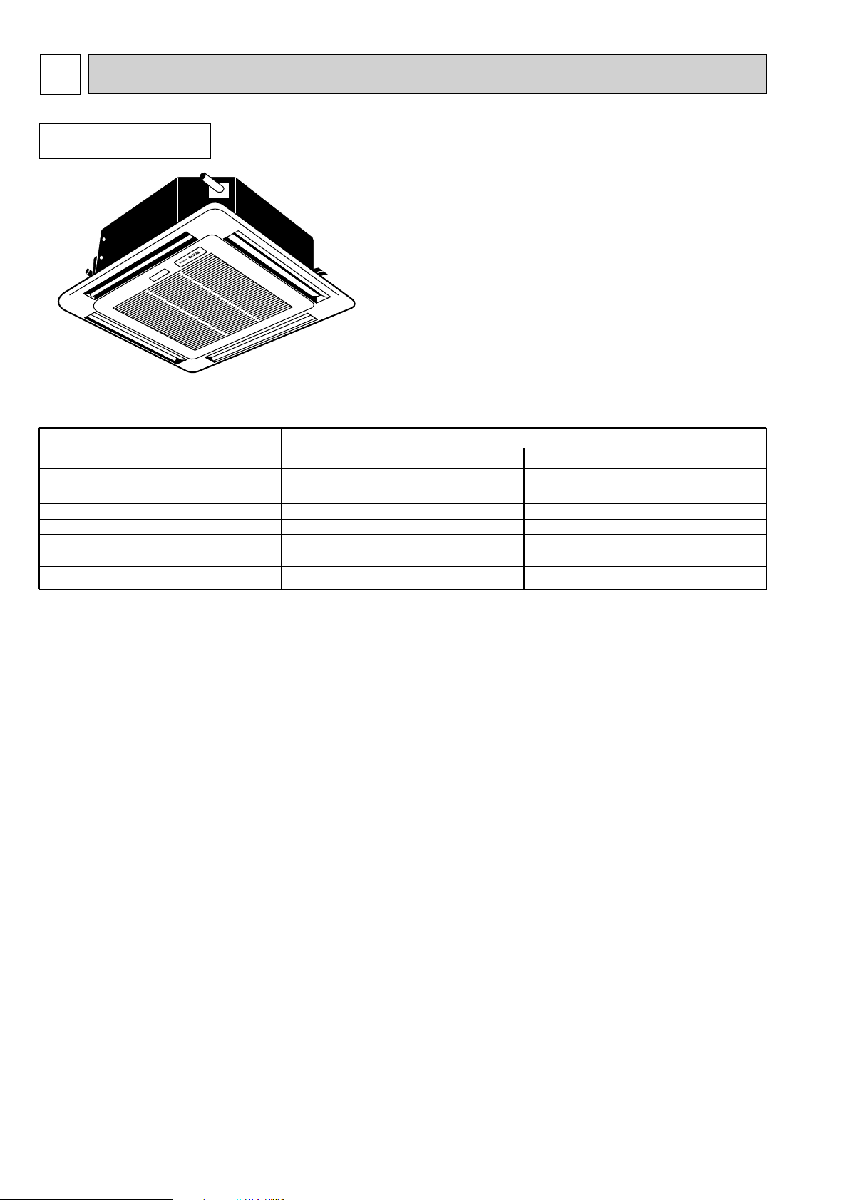
FEATURES
Series PLFY
Indoor unit
Models
PLFY-P32VKM
PLFY-P40VKM
PLFY-P50VKM
PLFY-P63VKM
PLFY-P80VKM
PLFY-P100VKM
PLFY-P125VKM
Ceiling Cassettes
Cooling capacity/Heating capacity
W
3,700 / 4,100
4,700 / 5,200
5,800 / 6,600
7,300 / 8,300
9,300 / 10,500
11,600 / 13,000
14,500 / 16,300
kcal/h
3,150 / 3,550
4,000 / 4,500
5,000 / 5,600
6,300 / 7,100
8,000 / 9,000
10,000 / 11,200
12,500 / 14,000
1.PURSUING CONPACTNESS
(1)Panel size and body volume reduced to 64% of previous models
The width and depth of the panel have been reduced by 19cm respectively,resulting in a compact model which fits
smaller environments (like shops) perfectly.
(2)Multi-application panels flexibly adapt to installation conditions.
Space panel and Wide panel may be installed on ceilings with shallow depth using the exiting opening .
2."SMUDGE-FREE", PRECISELY TARGETED AIRFLOW SYSTEM
The new control system regulates airflow to prevent smudging. Aprojection inside the air passage distributes air evenly
over the top and bottom of the vane. Two projections on the air outlet work to prevent cooled air from rising to the
celling, and also to stop outside air being dragged into the cooled air stream.
3.AIRFLOW ADJUSTABLE TO ANY INDOOR ENVIRONMENT
Airflow can be adjusted according to celling height and the number of air outlets. "Wide Zoming Flow" creates
anoptimum airflow for any indoor environment.
4.A FURTHER REFINEMENT OF COMFORT WITH NOISE SUPPRESION
The celling 4-way airflow cassette has a special "silent-design". The "2-Tap"system allows a choice between silent and
standard modes according to the height of the cellig. For ordinary residenced which have a low celling, selection of the
silent mode will result in remarkable noise reductions.
5.ECONOMICAL AND EASY MAINTENANCE
(1)Push-open grill
Filter clogging is widely recognized as a cause of reduced perfomance, but up until now it has been troublesome to
clean filters. With the "push-open grill" the fillter can be smoothly opened out at the push of a button, enabling speedy
cleaning.
(2)An unprecedented level of vane-cleaning
The unique airflow system prevents the intake of indoor air. Dewing therefore does not occur, and the vane is flockless.
The resulting level of dirt on the vane due to tobacco smoke, dust, etc. is very light,and can be wiped off easily with a
neutral detergent
(3)Long-life fillter
This new celling 4-way airflow cassette employs a long life fillter which requires no maintenance for up to 2,500 hours of
operation in general office environments. It adds uo to an ideal blend of comfort and low maintenance.
2
Page 3
6.COMPACT DIMENSIONS MEAN EASY INSTALLATION
(1)Carefree suspension work with lightweight unit
The new unit weighs in at 20kg (9kg lighter than the previous model) and is easy to handle and install. What's more,
suspension work is facillitated by compact dimensions ensuring a snug fit.
(2)Smooth installation with "one-direction"bolts
Suspension bolts can be fixes consistently from one direction easing suspension work.
(3)Trouble-free fitting work with slender refrigerant piping
Refrigerant piping has been reduced in size, and pipe-curving work at the installation site can now be completed quickly
and economically. In addition, refrigerant and drain piping are set at different corners, which means that flare connections
and drain piping heat insulation work can be smoothly and reliably implemented.
(4)Easy-access terminal and control panels for efficient wiring
When performing wiring work, progress can be checked on the power source terminal and control panels simply by
removing the electrical parts cover. Adress setting can also be done easily from beneath at a convenient angle.
(5)"One-push"to provisionally position front panel
Panel weight has been redused from 7kg to 3.7kg. The previous 3-step process for provisionally positioning the panel
has been streamlined, and now a simple "one-push" action at the diagonal corners fixed it into place, resulting in major
time-saving.
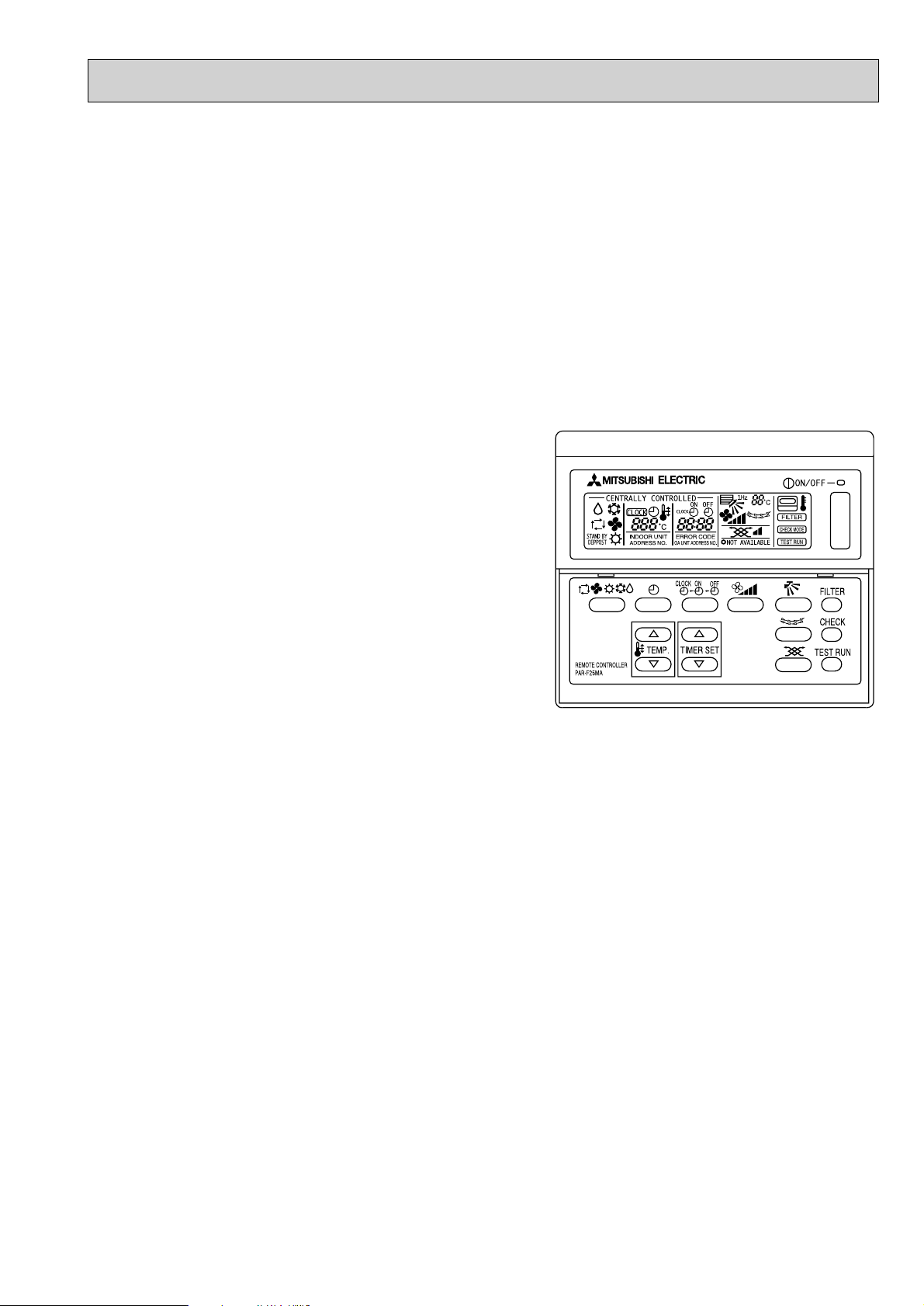
7.ADVANCED MICROPROCESSOR [PAR-F25MA]
(1)Easy to use microprocessor
1)Ultra-thin remote controller
The streamlind,square controller is designed to blend well with
any interior.Also,the sophisticated microprocessor allows you to
easily carry out a wide range of operations.
2)Attractive liquid crystal display(LCD)
The unit´s operation mode,set temperature,room
temperature,timer setting,fan speed,louver oper-ation,and air flow
direction are displayed on the remote controller´s easy-to-read
Liquid Crystal Dis-play(LCD).
3)Convenient 24-hour ON-OFF timer
The timer switches Mr.SLIM on and off automati-cally at the time
you set. Once the timer is set,the remaining time is shown on the
LCD
3
Page 4

2
SAFETY PRECAUTION
Cautions for devices that use R407C refrigerant.
· Do not use the existing refrigerant piping.
-The old refrigerant and refrigerator oil in the existing piping contains a large amount of chlorine which may cause the
refrigerator oil of the new unit to deteriorate.
· Use “low residual oil piping”.
-If there is a large amount of residual oil (hydraulic oil, etc.) inside the piping and joints, deterioration of the refrigerator oil
will result.
· Store the piping to be used during installation indoors and keep both ends of the piping sealed until just before
brazing. (Store elbows and other joints in a plastic bag.)
-If dust, dirt, or water enters the refrigerant cycle, deterioration of the oil and compressor trouble may result.
· Use Suniso 4GS or 3GS (small amount) as the refrigerator oil to coat flares and flange connection parts.
-The refrigerator oil used with the air conditioner is highly hygroscopic. If it is used, water may be mixed in and deterioration
of the refrigerator oil may result.
· Use liquid refrigerant to seal the system.
-If gas refrigerant is used to seal the system, the composition of the refrigerant in the cylinder will change and performance
may drop.
· Do not use a refrigerant other than R407.
-If another refrigerant (R22, etc.) is used, the chlorine in the refrigerant may cause the refrigerator oil to deteriorate.
· Use a vacuum pump with a reverse flow check valve.
-The vacuum pump oil may flow back into the refrigerant cycle and cause the refrigerator oil to deteriorate.
4
Page 5
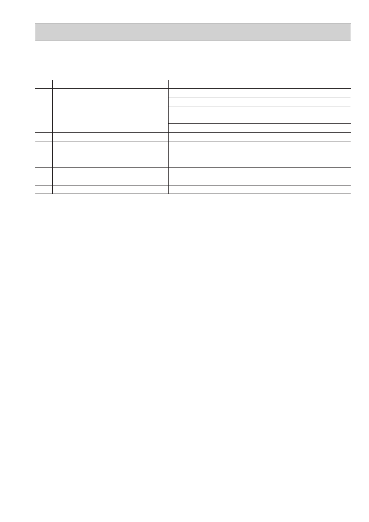
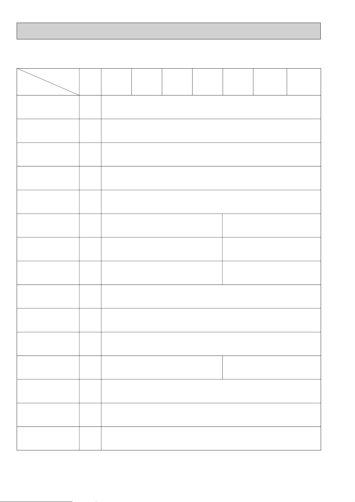
[1] Service tools
Use the below service tools as exclusive tools for R407C refrigerant.
No. Tool name Specifications
1 Gauge manifold ·Only for R407C.
·Use the existing fitting SPECIFICATIONS. (UNF7/16)
·Use high-tension side pressure of 35kgf/cm
2 Charge hose ·Only for R407C.
·Use pressure performance of 52kgf/cm2or over.
3 Electronic scale
4 Gas leak detector ·Use the detector for R134a or R407C.
5 Adapter for reverse flow check. ·Attach on vacuum pump.
6 Refrigerant charge base.
7 Refrigerant cylinder. ·For R407C ·Top of cylinder (Brown)
·Cylinder with syphon
8 Refrigerant recovery equipment.
[2] Notice on repair service
·After recovering the all refrigerator in the unit, proceed to working.
·Do not release the refrigerant in the air.
·After complete the repair service, recharge the cycle with the specified amount of the
liquid refrigerant.
2
or over.
5
Page 6
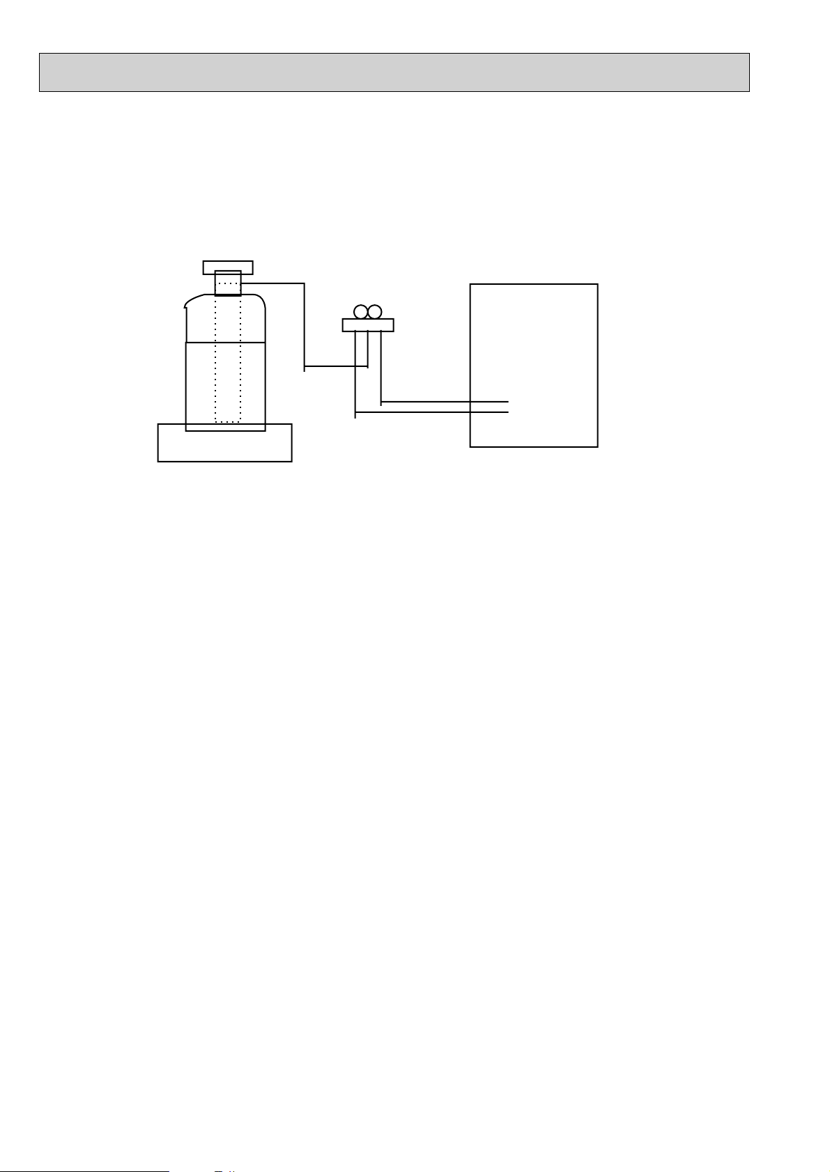
[3] Refrigerant recharging
Gravimeter
Unit
(1) Refrigerant recharging process
1Direct enclosure from the bomb.
·Comfirm that R407C bomb on the market are syphon pipe.
·Leave the syphon pipe bomb raising and recharge it.
(By liquid refrigerant)
(2) Recharge in refrigerant leakage case
·After recovering the all refrigerator in the unit, proceed to working.
·Do not release the refrigerant in the air.
·After complete the repair service, recharge the cycle with the specified amount of the
liquid refrigerant.
6
Page 7
3
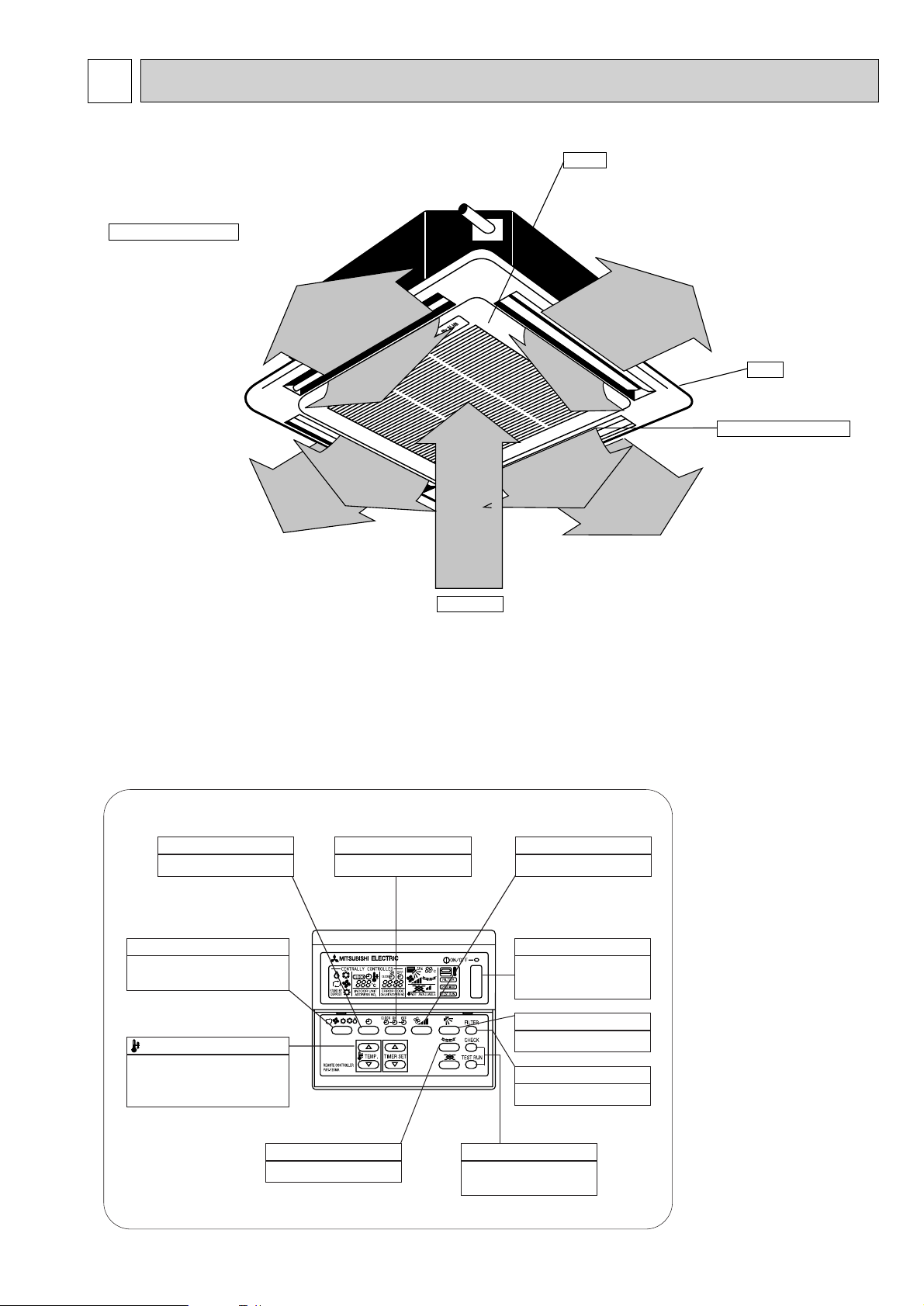
Auto Air Swing Vane
Disperses airflow up and
down and adjusts the angle
of airflow direction.
Grill
Filters
Remove dust and pollutants
from inhaled air
Horizontal Air Outlet
Sets airflow horizontal automatically
during cooling or dehumidifying.
Air Intake
Inhales air from room.
PART NAMES AND FUNCTIONS
● Indoor (Main) Unit
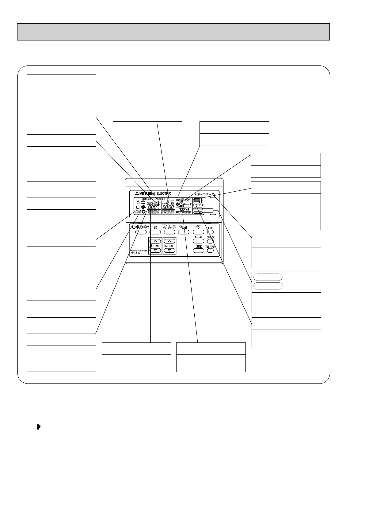
● Remote controller
● Operation buttons
TIMER button
This switches between continuous
operation and the timer operation.
OPERATION SWITCH button
Press this button to switch the cooler
electronic dry (dehumidify) automatic and
heater modes.
TEMP ADJUSTMENT button
This sets the room temparature The
temparature setting can be performed in 1°C
units
Setting range
Cooler 19°C to 30°C
[PAR-F25MA]
● Once the controls are set, the same operation mode can
be repeated by simply pressing the ON/OFF button.
TIME SETTING button
This sets of switches the current time.
start time and stop time.
LOUVER button
This switches the horizontal fan
motion ON and OFF.
(This button does not operate in this
model)
CHECK-TEST RUN button
Only press this button to perform an
inspection check or test operation Do
not use it for nomal operation.
AIR SPEED button
This sets the ventilation fan speed.
ON/OFF button
This swiches between the operation
and stop modes each time it is
pressed. The lamp on this button
lights during operation.
AIR DIRECTION button
This adjusts the vertical angle of the
ventilation.
FILTER button
This resets the filter service indication
display.
7
Page 8
4
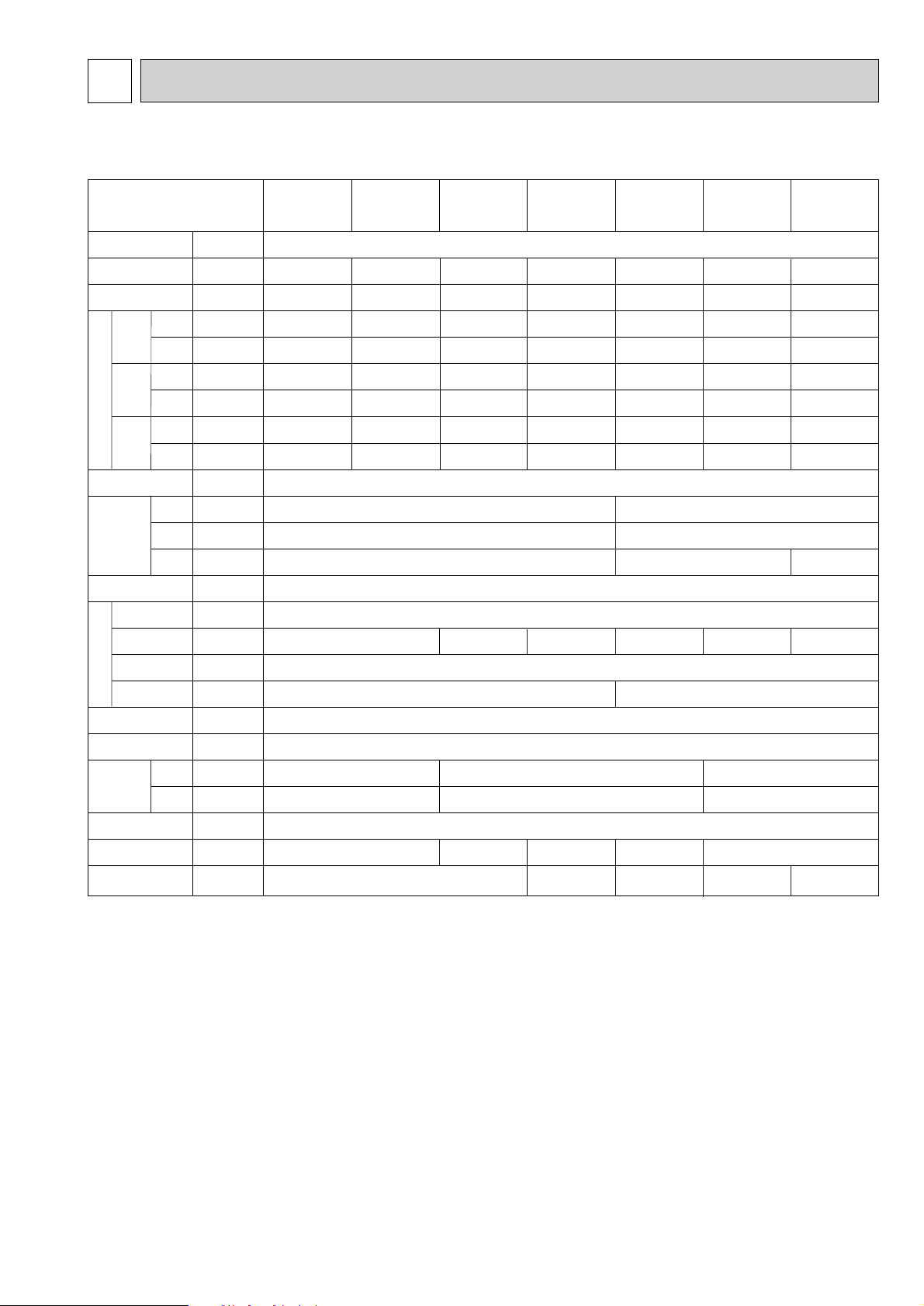
● Display
CENTRALLY
CONTROLLED display
This indicates when the unit is
controlled by optional features such
as central control type remote
controller.
TIMER display
This indicates when the continous
operation and time operation modes
are set.
It also display the time for the timer
operation at the same time as when
it is set.
OPERATION MODE display
This indicates the operation mode.
STANDBY display
This indicates when the standby
mode is set from the time the sleep
operation starts until the heating air
is discharged.
DEFROST display
This indicates when the defrost
operation is performed.
CLOCK display
The current time , start time and stop
time can be displayed in tensecond
intervals by pressing the time switch
button. The start time or stop time is
always displayed during the timer
operation.
In this display example on the
bottom left, a condition where all
display lamps light is shown for
explanation purposes although this
differs from actual operation.
AIR DIRECTION display
The selected fan speed is displayed.
FAN SPEED display
This displays the air direction.
ROOM TEMPERATURE display
The temperature of the suction air is
displayed during operation. The
display range is 8° to 39°C. The
display flashes 8°C when the actual
temperature is less than 8° and
flashes 39°C when the actual
temperature is greater than 39°C.
Operation lamp
This lamp lights during operation,
goes off when the unit stops and
flashes when amalfunction occurs.
CHECK MODE
TEST RUN
This display lights in the check mode
or when a test operation is
performed.
display
FILTER display
CHECK display
This indicates when a malfunction
has occurred in the unit which should
be checked.
SET TEMPERATURE display
This displays the selected setting
temperature.
Caution
● Only the Power display lights when the unit is stopped and power supplied to the unit.
● When power is turned ON for the first time the (CENTRAL CTRL) display appears to go off momentarily but this is not a
malfunction.
● When the central control remote control unit, which is sold separately, is used the ON-OFF button, operation switch button
and TEMP adjustment button do not operate.
● “NOT AVAILABLE” is displayed when the Air speed button are pressed.This indicates that this room unit is not equipped
with the fan direction adjustment function and the louver function.
● When power is turned ON for the first time, it is normal that “H0” is displayed on the room temperature indication (For max.
2minutes). Please wait until this “H0” indication disappear then start the operation.
8
POWER display
This lamp lights when electricity is
supplied to the unit.
This lamp lights when the filter need
to be cleaned.
Page 9
4
SPECIFICATION
4-1. Specification
Item
Power
Cooling capacity
Heating capacity
Cooling
Power
supply
Heating
Cooling
Starting
current
Heating
Cooling
Power
factor
Electric charocteristic
(munsell symbol)
dimensions
Out
Heating
Exteior
Height
Width
Depth
Heat exchanger
Fan x No
F
Air flow #3
a
External
n
static pressure
Fan motor
Output
Insulator
Air filter
Gas
Pipe
dimensions
side
Liquid
side
Drain pipe size
Noise level
PLFY-P32VKM PLFY-P40VKM PLFY-P50VKM PLFY-P63VKM PLFY-P80VKM PLFY -P100VKM PLFY-P125VKM
V•Hz Single phase 220V-240V 50 HZ
kcal/h 3,150 4,000 5,000 6,300 8,000 10,000 12,500
kcal/h 3,550 4,500 5,600 7,100 9,000 11,200 14,000
kw 0.13 0.13 0.14 0.15 0.17 0.21 0.22
kW 0.13 0.13 0.14 0.15 0.17 0.21 0.22
A 0.60 0.60 0.64 0.68 0.77 0.95 1.00
A 0.60 0.60 0.64 0.68 0.77 0.95 1.00
%------%-------
-Unit: Galranized sheets • Standard grill:ABS tesin acrylic coating Munsell<0.70Y 8.59/0.97>
mm 298<30> 297<30>
mm 660<760> 840<950>
mm 660<760> 840<950> 1360<1470>
- Cross fin
Turbo fan x 1
k/min 15-14.5-14-13 16-15-14-13 17-16-15-14 22-20-18-16.5 26- 24 -2 1. 5- 19 .5 30-27.5-25-22.5
Pa 0
kW 0.090
Polyethylene sheet
PP honey comb
[mm 12.7<1/2”> 15.88<5/8”> 19.05<3/4”>
[mm 6.35<1/4”> 9.52<3/8”> 9.52<3/8”>
[mm PVC pipe VP-25 connectable
dB(A) 35-34-32.5-31 37-35.5-34-32 39-38-36.5-35 38-35-32-30 42-39-36-34
Product weight
kg 19<3.7> 20<3.7> 28<5> 29<5> 37<9>
Note 1. Rating conditions(JIS B 8616)
Cooling: Indoor: 27°C DB. 19.5°CWB
outdoor: 35°C DB.
Heating: Indoor: 21°CDB
outdoor: 7°CDB. 6°CWB
Note 2. The number indicated in < > is just for the grill.
Note 3. Air flow and the noise level are indicated as High-Middium 1-Middium 2-Low.
9
Page 10
4-2. Electrical parts specifications
Model
Parts
name
Tranrsformer T (Primary) 50/60Hz 220-240V (Secondry) (18.4V 1.7A)
Symbol
PLFY -P32VKM PLFY-P40VKM PLFY-P50VKM PLFY-P63VKM PLFY -P80VKM PLFY-P100VKM PLFY -P125VKM
Room temperature
thermistor
Liquid pipe thermistor
Gas pipe thermistor TH23 Rresistance 0:/15k',10:/9.6k',20:/6.3k',25:/5.4k',30:/4.3k',40:/3.0k'
Fuse FUSE 250V 6.3A
(Indoor controller board)
Fan motor MF
(with Inner-thermostat)
Inner-thermostat
(Fan motor)
Fan motor capacitor C1 2+ x 400V 4+ x 460V
Vane motor MV
(with limit switch)
TH21 Resistance 0:/15k
TH22 Resistance 0:/15k',10:/9.6k',20:/6.3k',25:/5.4k',30:/4.3k',40:/3.0k'
6-pole OUTPUT 30W
OFF 125:±5:
ON 85:±20:
',10:/9.6k',20:/6.3k',25:/5.4k',30:/4.3k',40:/3.0k'
6-pole Output 90W
PA1-V30F
MC8 200V-240V
2.5/2W 5/6R.P.M
D17A6P90MS
OFF 130:±5:
ON 90:±20:
Drain-up mechanism DP
Drain sensor DS
Linear expansion valve LEV
Electric heater H2 240V 28.8W
(Condensation proof)
Power supply terminal
block
Transmission terminal
block
10
Heater resistance 82
Thermistor resistance 0:/15k
DC12V Stepping motor drive port
dimension 3.2
TB2 (L,N,;) 330V 30A
TB5 (M1,M2,S) 330V 30A
'/25:
(0~2000pulse)
'
EDM-402ME
',10:/9.6k',20:/6.3k',25:/5.4k',30:/4.3k',40:/3.0k'
PCD-4N230ME
INPUT 17/15W 36R/Hr
DC12V Stepping motor drive
port dimension 5.2
EDM-804ME
(0~2000pulse)
'
Page 11
5
243
42
166
156
65
75
1
2
760
760
466
66
35
460
66 35
460
466
135
435
54
+3
-2
115
65~80
30
298
253
54
+3
-2
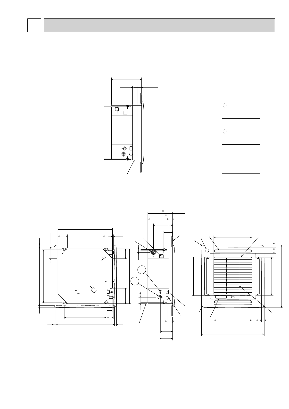
Air intake hole
Optional high-efficiency filter
Drain pipe
VP-25 connection
Control wire entry
Power line entry
Feeding hole
(Drain pump)
Suspension bolt M10
or W3/8
Suspension bolt lower edge
Ceiling surface
Leave space of 10~15mm between the
top surface of the unit and the ceiling slab
A
Refrigerant piping side
electric wire entry side
Vane motor
Grill
Air outlet hole
Air outlet hole
Air intake hole
4-Auto vanes
Air intake grill
Intake grill opening/closing side
Ceiling hole
Suspension bolt pitch
13
68
660
660
117
117
640
117
117
186
77
507
Suspension bolt pitch
Ceiling hole
690~710
25~3525~35
690~710
25~35 25~35
Drain hole
Terminal block for control
Terminal block for
power supply
NOTE 1.The electrical parts box may be removed during servic-
ing.When connecting the power line and the control
wire,provide enough length to the electric wires.
NOTE 2.When installing the optional high-efficiency filter,the
dimension between the transom and ceiling shall be
more than 440mm. Also,when installing the optional
fresh air intake casement or the multi-functional case-
ment,the dimension between the transom and ceiling
shall be more than 440mm. (The optional high-
efficiency filter can also be installed.)
64
OUTLINES AND DIMENSIONS
PLFY-P32VKM,PLFY-P40VKM
PLFY-P50VKM,PLFY-P63VKM
2
(12.7mmdia)
Refrigerant pipe
flared connection
Unit : mm
1/2F
5/8F
(15.88mmdia)
Refrigerant pipe
flared connection
1
Models
1/4F
(6.35mmdia)
Refrigerant pipe
flared connection
PLFY-32VKM
PLFY-40VKM
3/8F
(9.52mmdia)
Refrigerant pipe
flared connection
PLFY-P50VKM
PLFY-P63VKM
11
Page 12

PLFY-P80VKM
Suspension bolt pitch
Ceiling hole
950
950
20~45 20~45
50
65
50
65
581
581
9090
130
350
100
187
100 100
159
16
159
98
840
Liquid pipe
Gas pipe
2
1
Ceiling hole
Suspension bolt pitch
A
C
D
Optional high-efficiency filter
Ceiling serface
*Leave space of 10~15mm between the
top surface of the unit and the ceiling slab.
Branch buct
hole
581
581
177
147
Push button
10-{2.8
Barring hole
Branch buct
hole
Cut out hole
Branch duct hole details (Both side)
Suspension bolt M10
or W3/8
Control wire entry
Grill
Air outlet hole
Air intake grill
Air intake hole
Air outlet hole
4-Auto vanes
Vane motor
Air intake hole
Refrigerant piping side
electric wire entry side
Suspention bolt lower edge
Feeding hole(Drain pump)
Drain pipe
VP-25 connection
Drain hole
power supply
Power line entry
NOTE 1.For drainage piping use VP-25 PVC piping.
NOTE 2.For suspention bolts use M10 or W3/8 screws.
NOTE 3.The electrical parts box may be removed during servic-
ing. When connecting the power line and the control
wire,provide enough length to the electric wires.
NOTE 4.When installing the optional high-efficiency filter,the
dimention between the transom and ceiling shall be
more than 440mm. Also,when installing the optional
fresh air intake casement or the multi-functional case-
ment,the dimension between the transom and ceiling
shall be more than 440mm. (The optional high-
efficiency filter can also be installed.)
60
135
240
44
+3
-2
105
44
+3
-2
30
225
55~70
432
*297
253
374286
860~910
860~910
605
810
20~45 20~45
197
197
159
840
192
159
Terminal block for
Terminal block for control
PLFY-P100VKM
Unit : mm
79
D
84
C
2
1
Models
89
5/8F
(15.88mmdia)
Refrigerant pipe
Refrigerant pipe
Refrigerant pipe
flared connection
3/8F
(9.52mmdia)
Refrigerant pipe
flared connection
PLFY-P80VKM
89
3/4F
(19.05mmdia)
flared connection
3/8F
(9.52mmdia)
flared connection
PLFY-P100VKM
12
Page 13

PLFY-P125VKM
Vane motor
581
Grill details
Air intake hole
B
A
Refrigerant piping side
electric wire entry side
20~4520~45
4-Auto vanes
Air intake hole
1101
Air outlet hole
1101
1470
Branch duct
hole
1380~1430
1125
Ceiling hole
Suspension bolt pitch
Grill
5065581
950
Air outlet hole
50
65
Air intake grill
159
16
187
130
100
10-{2.8
Barring hole
Cut out hole
90
*297
253
225
105
350
30
*Leave space of 10~15mm between the
top surface of the unit and the ceiling slab.
-2
44
+3
100100
90
Branch duct hole details(Both side)
Drain pipe
VP-25connection
810
860~910
Ceiling hole
Suspension bolt pitch
159
20~45 20~45
159
Terminal block for
power supply
Branch duct
hole
1360
Drain hole
Terminal block for control
89
98
192
84
159
374286
840
Feeding hole(Drain pump)
197
Suspension bolt M10
60
Refrigerant pipe{9.52
Flared connection3/8F
Refrigerant pipe{9.52
or W3/8
Ceiling surface
Control wire entry
Power line entry
147
177
197
Flared connection3/4F
432
240
-2
135
44
+3
Suspension bolt lower edge
B
55~70
NOTE 1.For drainage piping use VP-25 PVC piping.
NOTE 2.For suspension bolts use M10 or W3/8 screws.
NOTE 3.The electrical parts box may be removed during servic-
ing.When connecting the power line and the control
wire,provide enough length to the electric wires.
NOTE 4.When installing the optional high-efficiency filter,the
dimension between the transom and ceiling shall be
more then 440mm.Also,when installing the optional
fresh air intake casemant or the multi-functional case-
ment,the dimension between the transom and ceiling
shall be more than 440mm. (The optional high-
efficiency filter can also be instlled.)
Optional high-efficiency filter
Gas pipe
Liquid pipe
13
Page 14

6
PE
GRY
GRY
BLK
BLK
BLK
BLK
BLK
BLK
RED
RED
WHT
RED
YLW
ORN
BRN
BLU
M1
TO OUTDOOR UNIT
BC CONTROLLER
REMOTE CONTROLLER
DC24-30V
M2
TB5
(SHIELD)
AC18.4V
AC220-240V
BLU
RED
BLU
BLU
BRN
BRN
YLW
YLW
YLW
YLW
WHT
RED
RED
WHT
BLK
(WHT)
FAN1
CNT
(WHT)
TRANS
(GRN)
CNV
(BLU)
CNP
6.3A
250V
FUSE
(RED)
CND
CN3T
TRANS
(RED)
BLU
BLU
M-NET
(BLU)
CN2M
BRN
BRN
CN23
(GRN)
VANE
POSITION
4
1
CN41
(WHT)
HA
1
CN32
3
(WHT)
REMOTE
SWITCH
CN50
DRAIN
(RED)
CN20
(RED)
INTAKE
CN21
LIQUID
(WHT)
CN29
(BLK)
GAS
CN60
LEV
(WHT)
5
(WHT)
CENTRALLY
CONTROL
1
CN51
1
5
(WHT)
REMOTE
INDICATION
CN52
CN42
(RED)
ADDRESS
CN81
(RED)
ADDRESS
12
HUMIDIFIER
CN25
A.B
SW5
240V
220V
SWA
3
2
1
SWB
2
3
4
1
2
3
4
CN43
ADDRESS
(RED)
1
2
3
4
5
6
7
8
ADDRESS
CN82
(RED)
CONNECTION
No.
SW14
0
SWC
SW1
87654321
OFF
ON
109
00
SW11
SW12
1ST.DIGIT
2ND.DIGIT
3RD.DIGIT
6
BLU
RED
GRN/YLW
L
N
TB2
TO NEXT
INDOOR UNIT
PULL BOX
FUSE(15A)
BREAKER
(15A)
POWER SUPPLY
~/N 220-240V
50Hz
SR3
SR1
ZNR
DS
4
I.B
8
TH21
SW2
10
LEV
TH22
TH23
T
32
SW4
1
10N12345678923456
SW3
0FF
LED4
LED3
LED5LED2
LED1
4
0N
0FF
27 510 61
H2
GRILLE
MV
LS
1
53
87 23456
F.C
1
1
2
4
3
65 1234
2112
1
MF
32
1432
13
13
13
13
64523
DP
21
C
321
31
14532122112
1
1
2
1
2
}
WIRING DIAGRAM
PLFY-P32VKM,PLFY-P40VKM
PLFY-P50VKM,PLFY-P63VKM
PLFY-P80VKM,PLFY-P100VKM
PLFY-P125VKM
LEGEND
SYMBOL
I.B
INDOOR CONTROLLER BOARD
CN25 HUMIDIFIER CONNECTOR
CN32
REMOTE SWITCH CONNECTOR
CN41
HA TERMINAL-A CONNECTOR
CN51
CENTRALLY CONTROL CONNECTOR
CN52
REMOTE INDICATION CONNECTOR
SW2
CAPACITY CORD SWITCH
SW3
FUNCTION SELECTOR
SW4
UNIT SELECTOR
X1
DRAIN UP MECH RELAY
DEW PREVENTION HEATER RELAY
X3
VANE RELAY
X4
1.At servicing for outdoor unit,always follow the wiring diagram of outdoor unit.
2.Symbol(S) of TB5 is the shield wire connection.
3.Symbols used in wiring diagram above are, :Terminal block, :Connector.
4.The setting of the SW2 dip switches differs in the capacity.
For the detail,see the table below.
ON
OFF
ON
OFF
ON
OFF
MODELS SW2
PLFY-P32VKM
PLFY-P40VKM
PLFY-P50VKM PLFY-P80VKM
5.Please set the switch SW5 according to the power supply voltage.
Set SW5 to 240V side when the power supply is 230 and 240 volts.
When the power supply is 220 volts,set SW5 to 220V side.
MODELS SW2
PLFY-P63VKM
654321
PLFY-P100VKM
654321
654321
NOTE
ON
OFF
ON
OFF
ON
OFF
654321
654321
654321
FAN MOTOR RELAY
ZNR
VARISTOR
FUSE
FUSE(6.3A)
F.C
FAN PHASE CONTROL
TH21
ROOM TEMPERATURE THERMISTOR
(0:/15k',25:/5.4k')
TH22
LIQUID PIPE THERMISTOR
(0:/15k',25:/5.4k')
TH23
GAS PIPE THERMISTOR
(0:/15k',25:/5.4k')
MODELS
PLFY-P125VKM
14
NAME
ON
OFF
<fig1>
SW2
654321
SYMBOL
NAME
T TRANSFORMER
DS
DRAIN SENSOR
DP
DRAIN WATER LIFTING-UP MACH.
MF
FAN MOTOR (WITH INNER THERMO.)
C
FAN MOTOR CAPACITOR
MV
VANE MOTOR
LS
LIMIT SWITCH
H2
DEW PREVENTION HEATER
TB2
POWER SUPPLYTERMINAL BLOCK
TB5
TRANSMISSION TERMINAL BLOCK
LEV
LINEAR EXPANSION VALVE
A,B
ADDRESS BOARD
MODE SELECTOR
SW1(A,B)
SW5(A,B)
VOLTAGE SELECTOR
SW11(A,B)
1ST DIGIT ADDRESS SETTING
SW12(A,B)
2ND DIGIT ADDRESS SETTING
SW14(A,B)
CONNCTION NO.
SWA(A,B)
CEILING HEIGHT SELECTOR
SWB(A,B)
DISCHARGE AIR DIRECTION
SWC(A,B)
OPTION SELECTOR
Page 15

REFRIGERANT SYSTEM DIAGRAM7
Strainer (#50mesh)
Strainer (#100mesh)
Strainer (#100mesh)
Heat exchanger
Room temparature thermistor TH21
Gas pipe thermistor TH23
Liquid pipe thermistor TH22
Linear expansion valve
Gas pipe
Flare connection
PLFY-P32VKM,PLFY-P40VKM
PLFY-P50VKM,PLFY-P63VKM
PLFY-P80VKM,PLFY-P100VKM
PLFY-P125VKM
Item
Gas pipe
Liquid pipe
Capacity
PLFY-P32,P40VKM
{12.7<1/2F>
PLFY-P50,P63,P80VKM
{15.88<5/8F>
PLFY-P100,P125VKM
{19.05<3/4”>
{6.35<1/4F> {9.52<3/8F> {9.52<3/8”>
15
Page 16

8
TROUBLE SHOOTING
8-1. How to check the parts PLFY-P•VKM
Parts name Check points
Room temparature
thermistor
Liquid pipe thermistor
Gas pipe thermistor
(TH21)
(TH22)
(TH23)
Disconnect the connector, then measure the resistance using a tester.
(Sorrounding temperature 10°C~30°C)
Normal
4.3k'~9.6k'
Abnormal
Open or short
(Refer to the thermistor)
Trans
CNT T CN3T
Red Blue
1
2
3
White
Blue
1
2
3
Vane motor
Fan motor
Relay connector
1
Red
White
2
3
Black
Protector
Linear expansion
valve
LEV
White
Yellow
Orange
Blue
Red
Brown
CN60
Drain-up
mechanism
Gray
1
2
Gray
Drain sensor
Disconnect the connector and measure the resistance using a tester.
Normal
CNT(1)-(3)
CN3T(1)-(3)
Measure the resistance between the terminals using a tester.
(Surrounding temperature 20;~30;)
Normal
App.14k'
Measure the resistance between the terminals using a tester.
Motor terminal
1
Relay connector
2
3
Disconnect the connector then measure the resistance valve using a tester.
Refer to the next page for a detail.
1
2
3
4
5
6
Measure the resistance between the terminals using a tester.(Surrounding temperature : 20;~30;)
or
Red-Black
White-Black
(1)-(5)
White-Red
Yellow-
Normal
327'
Measure the resistance between the terminals using a tester.
App.45'
App.1'
Abnormal
Open or short
P32,P40,P50,P63
136.2' 27.1'
197.5' 65.5'
Normal
(2)-(6)
Blown
Orange-Red
150' ±10%
Abnormal
Open or short
Normal
PLFY-P•VKM
(3)-(5)
Abnormal
Open or short
P80,P100,P125
(4)-(6)
Blue-Brown
Abnormal
Open or short
Abnormal
Open or short
16
1
2
3
4
5
(1)-(3)
(4)-(5)
Normal
82'
4.3k'~9.6k'
Abnormal
Open or short
(Refer to the thermistor)
Page 17

<Output pulse signal and the valve operation>
D
A
E
B
C
Open
Extra tightning (80~100pulse)
Pulse number
2000 pulse
Opening a valve
all the way
Close
Valve position (capacity)
Thermistor
()
Linear
expansion
valve
150
'
10%.
Output
(Phase)
{1
{2
{3
{4
Linear expansion valve operation
➁
1
ON
ON
OFF
OFF
2
OFF
ON
ON
OFF
Output
3
OFF
OFF
ON
ON
4
ON
OFF
OFF
ON
Closing a valve : 1 → 2 → 3 → 4 → 1
Opening a valve : 4 → 3 → 2 → 1 → 4
The output pulse shifts in above order.
❈ 1. When linear expasion valve operation stops, all output phase
become OFF.
2. At phase interruption or when phase does not shift in order,
motor does not rotate smoothly and motor will locks and vibrates.
❈ When the switch is turned on, 2200 pulse opening valve signal
will be send till it goes to
A point in order to define the valve
position.
When the valve move smoothly, there is no noise or vibration
occurring from the linear expansion valve : however, when the
pulse number moves from E to A or when the valve is locked,
more noise can be heard than normal situation.
❈ Noise can be detected by placing the ear against the screw
driver handle while putting the screw driver to the linear
expansion valve.
Trouble shooting
➂
Symptom
Operation circuit
failure of the micro
processor.
Linear expansion
valve mechanism is
locked.
Short or breakage of
the motor coil of the
linear expansion
valve.
Valve doesn't close
completely
(thermistor leaking).
Wrong connection of
the connector or
contact failure.
Check points
Disconnect the connector on the controller board, then
connect LED for checking.
LED1S
Pulse signal will be sent out for 10 seconds as soon as the
main switch is turn on. If there is LED with lights on or lights
off, it means the operation circuit is abnormal.
Motor will idle and make ticking noise when motor is operated
while the linear expansion valve is locked. This ticking sound
is the sign of the abnormality.
Measure the resistance between the each coil (red-white,
red-orange, brown-yellow, brown-blue) using a tester. It is
normal if the resistance is in the range of
To check the linear expansion valve, operate the indoor unit
in fan mode and at the same time operate other indoor units
in cooling mode, then check the pipe temperature <liquid
remote controller, it means the valve is not closed all the way.
It is not necessary to exchange the linear expansion valve, if
the leakage is small and not making any trouble.
Check the color of lead wire and missing terminal of the
connector.
pipe temperature> of the indoor unit by the
outdoor multi controller board operation
monitor. During fan operation, linear
expansion valve is closed completely and if
there are some leaking, detecting
temperature of the thermistor will go lower.
If the detected temperature is much lower
than the temperature indicated in the
6
5
4
3
2
1
Countermeasures
Exchange the indoor
controller board at drive
circuit failure.
Exchange the linear
expansion vale.
Exchange the linear
expansion valve.
If large amount of
thermistor is leaked,
exchange the linear
expansion valve.
Disconnect the connector
at the controller board,
then check the continuity.
17
Page 18

<Thermistor Characteristic graph>
Thermistor for
lower temperature
Room temparature thermistor(TH21)
Liquid pipe thermistor(TH22)
Gas pipe temparature thermistor(TH23)
Drain sensor(THD)
Thermistor R0=15k' ±3%
Fixed number of B=3480k' ±2%
< Thermistor for lower temperature >
50
40
30
Rt=15exp { 3480( ) }
1
273+t
0: 15k'
1
273
Resistance (K")
20
10: 9.6k'
20: 6.3k'
25: 5.2k'
10
30: 4.3k'
40: 3.0k'
0
-20 -10 0 10 20 30 40 50
Temperature (:)
Linear expansion valve
① Operation summary of the linear expansion valve.
• Linear expansion valve open/close through stepping motor after receiving the pulse signal from the indoor controller board.
• Valve position can be changed in proportion to the number of pulse signal.
<Connection between the indoor controller board and the linear expasion valve>
Controller board
Relay connector
DC12V
Linear expansion valve
4
M
6
2
5
White
1
Red
3
Orange
Blue
Brown
Yellow
[4
[3
[2
[1
Brown
5
1
3
4
6
Red
Blue
Orange
Yellow
White
Connector(CN60)
62
5
4
3
2
1
Drive circuit
[4
[3
[2
[1
Note : Since the number of the connector at the controller board side and the relay connector are different, follow the color of
the lead wire.
18
Page 19

8-2. FUNCTION OF DIPSWICH
Switch Pole
1
2
3
4
SW1
Mode
Selection
5
6
7
8
9
10
SW2
Capacity
code
1~6
setting
Function
Operation by switch
ON OFF
Thermistor<Intake temperature
detection>position
Bult-in remote controller
Filter crogging detection ProvidedNot provided
Filter life 2,500hr 100hr
Air intake Effective Not effective
Remote indication switching Thermostat ON signal indication Fan output indication
Humidifier control
Always operated while the heat is ON
Air flow st Low Extra low
Heat thermostat OFF Setting air flow Reset to SW1-7
Auto reset function Effective Not effective
Power ON/OFF Effective Not effective
MODELS SW2 MODELS SW2 MODELS SW2
PLFY-P32VKM
PLFY-P40VKM
PLFY-P50VKM
OFF
OFF
ON
ON
ON
OFF
PLFY-P63VKM
123456
PLFY-P100VKM
123456
PLFY-P80VKM
123456
ON
OFF
ON
OFF
OFF
ON
123456
123456
123456
Indoor unit
Operated depends on the condition
PLFY-P125VKM
ON
OFF
123456
Remarks
Address board
<At delivery>
ON
OFF
12345678910
(Note1) Fan operation at Heating
mode
(Note2) Heater thermo ON is
operating.
(Note3) SW1-7=OFF, SW1-8=ON
→Setting air flow.
SW1-7=OFF, SW1-8=ON
→Indoor fan stop.
Indoor controller board
Set while the unit is off.
<At delivery>
Set for each capacity.
SW3
Function
Selection
10
SW4
Unit
1~3
Selection
Heat pump/Cool only Cooling only Heat pump
1
Louver Available Not available
2
Vane Available Not available
3
Vane swing function Available Not available
4
Vane holizontal angle Second setting First setting
5
Vane cooling limit angle setting
6
Indoor linear expansion
7
valve opening
Heater 4deg up Not effective Effective
8
Superheat setting temperature
9
Superheat setting temperature
ON
OFF
1234
Horizontal angle Down B,C
Effective Not effective
5deg 2deg
15deg 10deg
Indoor controller board
Set while the unit is off.
<At delivery>
ON
OFF
12345678910
(Note1) At cooling mode, each
angle can be used only 1
hour.
Indoor controller board
Set while the unit is off.
<At delivery>
ON
OFF
1234
19
Page 20

Operation by switchSwitch Pole Remarks
220V 240V
220V 240V
SWA
Set the
Ceiling
height
SWB
Dischar-
ge Air
Direction
SWC
Option
1~3
3
2
(High 2)
(High 1)
(Standard)
2 way
3 way
4 way
Option
standard
❈ Ceiling height can be changed depends on
Address board
SWB setting.
3
2
1
<At delivery>
3
2
1
Address board
SWB
SWA
2 way 3.5m 3.8m 3.8m
3 way 3.0m 3.3m 3.5m
4 way 2.7m 3.0m 3.5m
123
<At delivery>
2
3
4
Address board
When attach the optional high performance
filter elements (filter casement) to the unit, be
sure to attach it to the option side in order to
prevent the airflow reducing.
<At delivery>
Option
SW11
1st digit
address
setting
SW12
2nd degit
address
setting
SW14
Connect
ion No.
setting
SW5
Voltage
Selection
Rotary switch
Rotary switch
2
SW12
0
9
8
7
6
5
10
1
2
3
4
SW14
0
F
E
D
C
B
A
8
9
SW11
8
7
1
2
3
4
5
6
7
Address board
Address can be set while the
unit is stopped.
0
1
9
6
5
Address setting should be done when network
2
remote controller (PAR-F25MA) is being used.
3
4
1
<At delivery>
SW12
SW11
0
9
8
7
6
0
1
1
9
2
8
3
7
4
6
5
5
2
3
4
Address board
This is the switch to be used when the indoor
unit is operated with R2, R3 series outdoor
unit as a set.
<At delivery>
SW14
0
1
2
F
3
E
4
D
5
C
6
B
7
A
8
9
Address board
If the unit is used at the 230V or 240V area,
set the voltage to 240V.
If the unit is used at the 220V, set the voltage
to 220V.
<At delivery>
20
Page 21

9
DISASSEMBLY PROCEDURE
1. INDOOR UNIT
PLFY-P63VKM
OPERATING PROCEDURE PHOTOS&ILLUSTRATIONS
1. Removing the air intake grill
(1) Press the button.
(2) Open the intake grill 90°.
(3) Remove the chip.
(4) Slide the shaft in the hinge to the left and remove the
intake grill.
2. Removing the fan guard.
(1) Open the intake grill.
(2) Remove the 4 screws of the fan guard.
PUSH
Figure 1
PUSH button
Photo 1
Fan guard
Be careful on removing heavy parts.
Shaft
Intake grill
Fan guard screw
3. Removing the electrical parts box
(1) Remove the fan grand.
(2) Disconnect the lead wire of the vane motor from the clamp,
and disconnect the red connector (8P).
(3) Remove 2 of 4 screws from the electorical parts cover.
(4) Remove the electorical parts cover.
(5) Disconnect the following connectors from the box.
Red (3P) for the fan motor
White (2P) for the indoor coil trermistor
Blue (2P) for the drain pump
White (4P) for the drain sensor
(6) Disconnect the green anti-falling wire of the electrical parts
box.
(7) Remove 3 of 4 screws from the electrical parts box, and
loosen the other screw.
(8) Pull out the electrical parts box.
Electrical parts inside the box
Terminal block
Transformer
Indoor fan capacitor
Room temperature thermistor
Indoor controller board
4. Removing the fan motor
(1) Remove the fan guard.
(2) Remove the turbo-fan nut and radiator aluminum cap.
(3) Pull out the turbo fan.
(4) Disconnect the connector of the fan motor lead wire.
(5) Remove the 3nuts of fan motor.
Photo 2
Photo 3
Electrical box
Room
temperature
thermistor
Radiator
aluminum cap
Photo 4
Connerctor
Screws
Lead wire for
vane motor
Screws Transformer
ConnectorTerminal blockAnti-falling wire
Nut
Fan motorConnector
Box
cover
Clamp
Indoor
controller
board
Capacitor
nut
21
Page 22

OPERATING PROCEDURE PHOTOS&ILLUSTRATIONS
5. Removing the room temperature thermistor
(1) Remove the fan guard.
(2) Remove the electrical box cover
(3) Remove the holder and the room temperature thermistor
by pulling the catch.
(4) Disconnect the red connector, CN20, on the indoor
controller board.
6. Removing the indoor coil thermistor
(1) Remove the fan guard.
(2) Remove the electrical box cover.
(3) Remove the electrical box.
(4) Remove the turbo fan.
(5) Remove the screw of the service panel.
(6) Remove the service panel.
(7) Remove the indoor coil thermistor from the holder
attached to the copper pipe.
(8) Disconnect the 2-pin white connector.
Photo 5
Room
temparature
thermistor
Photo 6
Indoor controller board
Indoor coil thermistor
7. Removing the panel
(1) Open the intake grill.
(2) Disconnect the connector the vane motor.
(3) Remove 4 screws of the panel.
(4) Pulling the temporary handing hook, remove the panel.
8. Removing the drain pan
(1) Remove the panel.
(2) Remove the fan guard.
(3) Remove the rubber bushing.
(4) Drain the remaining water in the drain pan.
(5) Remove the electrical box cover.
(6) Remove the electrical box.
(7) Remove the screw of the V.A. cover, and remove the V.A.
cover.
(8) Remove each screw of the corner supports 1,2, and 3,
and remove the corner supports 1,2 and 3.
(9) Pull out the drain pan.
wPull the left and right of the pan gradually.
Be careful not to crack or damage the pan.
Photo 7
screws
Panel
Photo 8
Corner
support 2
VAcover
Mounting hole
Temporary hanging hook
Fan guard
Rubber
bush
Corner
support 3
screws
Temporary hanging hook
Screws
Corner
support 1
22
Page 23

OPERATING PROCEDURE PHOTOS&ILLUSTRATIONS
9. Removing the drain pump and drain sensor
(1) Remove the panel.
(2) Remove the fan guard.
(3) Remove the electrical parts cover.
(4) Remove the electrical parts box.
(5) Remove the drain pan.
(6) Remove 4 screws of the drain pump.
(7) Pulling the clip of the drain hose, pull out the drain hose
from the drain pump.
(8) Remove the drain senser and the holder.
(9) Pull out the drain pump.
10. Removing the heat exchanger
(1) Remove the panel.
(2) Remove the fan guard.
(3) Remove the electrical parts cover.
(4) Remove the electrical parts box.
(5) Remove the drain pan.
(6) Remove the turbo fan.
(7) Remove the screw of the coil support A.
(8) Remove 2 screws of the coil support B.
(9) Remove 2 screws of the coil.
(10) Remove 4 screws of the piping cover of the outer wall,
and pull out the piping cover.
Photo 9
Clip
Screws
Photo 10
Coil support A
Drain hose
Drain pump
Heat exchanger
Drain sensor
holder
Photo 11
Piping
cover
Coil support B
Coil screws
Screws of piping
cover
23
Page 24

PARTS LIST10
1
2
3
4
5
6
7
R01 29H 003
R01 29H 500
R01 29H 691
R01 29H 061
—
T7W B00 713
T7W A00 305
1
1
1
2
1
1
1
R.B
(BG88H096H01)
AIR OUTLET GRILLE
AIR FILTER
INTAKE GRILLE
HINGE
GRILLE HANGER
REMOTE CONTROLLER
REMOTE CONTROLLER CABLE
10m
No. Part No. Part Name Specification
Q'ty/set
Price
Unit
Amount
Remarks
(Drawing No.)
Wiring
Diagram
Symbol
Recom-
mended
Q'ty
PLFY-P32/P40/
P50/P63
VKM
PANEL PARTS
PLFY-P32VKM
PLFY-P40VKM
PLFY-P50VKM
PLFY-P63VKM
24
7
6
Page 25

PANEL PARTS
PLFY-P32VKM
PLFY-P40VKM
PLFY-P50VKM
PLFY-P63VKM
No. Part No. Part Name Specification
1
R01 29H 002
2
R01 29H 085
3
R01 29H 223
4
R01 29H 063
5
R01 31H 063
6
R01 29H 056
7
R01 29H 040
8
R01 29H 041
9
R01 08K 049
AUTO VANE
AIR GUIDE
VANE MOTOR
SPRING JOINT 1
SPRING JOINT 3
PUSH BUTTON
GRILLE GEAR (RIGHT)
GRILLE GEAR (LEFT)
LID(UP)
Q'ty/set
PLFY-P32/P40
/P50/P63
VKM
4
1
1
1
1
1
1
1
1
Remarks
(Drawing No.)
<3/SET>
Wiring
Diagram
Symbol
MV
Recommended
Q'ty
Unit
Price
Amount
25
Page 26

FUNCTIONAL PARTS
PLFY-P32VKM
PLFY-P40VKM
PLFY-P50VKM
PLFY-P63VKM
7
6
3
4
2
1
5
21
8
30
15
16
36
22
23
19
13
9
10
11
33
12
35
32
31
17
20
26
24
37
25
21
2628
27
29
Page 27

1
2
3
4
5
6
7
8
9
11
12
13
14
15
16
17
18
19
20
21
22
23
24
25
26
27
28
29
30
31
32
33
34
35
36
37
—
—
—
—
—
T7W E00 762
R01 29H 105
—
R01 41N 114
R01 08K 202
R01 41N 523
T7W E00 355
R01 W28 266
R01 W28 527
R01 55W 480
R01 57W 480
R01 58W 480
T7W E01 529
—
—
T7W A14 716
T7W A02 716
R01 29H 255
—
T7W E00 310
T7W 520 239
T7W E00 260
R01 06A 202
—
—
T7W 29H 675
R01 08K 097
R01 A48 524
R01 71N 241
R01 79N 202
R01 31K 535
R01 AJ8 401
R01 05A 304
T7W B01 294
1
1
1
1
1
1
3
1
1
1
1
1
1
1
1
1
1
1
1
1
1
1
1
1
1
1
1
1
1
1
1
1
1
1
1
1
1
1
1
1
1
1
1
3
1
1
1
1
1
1
1
1
1
1
1
1
1
1
1
1
1
1
1
1
1
1
1
1
1
1
1
1
1
1
1
1
1
1
1
1
3
1
1
1
1
1
1
1
1
1
1
1
1
1
1
1
1
1
1
1
1
1
1
1
1
1
1
1
1
1
1
PLFY-P·VKM
1
1
1
1
1
1
3
1
1
1
1
1
1
1
1
1
1
1
1
1
1
1
1
1
1
1
1
1
1
1
1
1
1
1
1
1
1
MF
TH22
DP
DS
TB2
TB5
C
I.B
F<I.B>
T
TH21
TH23
A.B.
(BG02Y348G06)
(BG00T672G08)
(BG00T672G09)
(BG00T672G10)
(BG00T673G02)
(BG00T718G06)
(BG00T713G05)
(BG00T712G06)
(BG25J542H04)
(BG00L601G22)
(BG00A662G18)
BASE
LEG
LEG
LEG
LEG
FAN MOTOR
MOTOR MOUNT
INNER COVER
TURBO FAN
INDOOR COIL THERMISTOR
DRAIN SOCKET
DRAIN PUMP
DRAIN SENSOR
DRAIN HOSE
HEAT EXCHANGER
HEAT EXCHANGER
HEAT EXCHANGER
DRAIN PAN
CORNER COVER
COVER (DRAM)
TERMINAL BLOCK
TERMINAL BLOCK
CAPACITOR
CONTROLLER CASE
INDOOR CONTROLLER BOARD
FUSE
TRANSFORMER
ROOM TEMPERATURE THERMISTOR
BELL MOUTH
ELECTRICAL PARTS COVER
FAN GUARD
SPL WASHER
DRAIN PLUG
SENSOR HOLDER
THERMISTOR
D/S PROTECTOR
EXPANSION VALVE
ADDRESS CABLE
ADDRESS BOARD
PAI-V30F
3P(L,N,;)
3P(1,2,3)
2.5µF 400V
250V 6.3A
No.
Part No. Part Name Specification
Q'ty/set Price
Unit
Amount
Remarks
(Drawing No.)
Wiring
Diagram
Symbol
Recom-
mended
Q'ty
10
P32 P40 P50
P63
Part numbers that are cicled are not shown in the figure.
27
Page 28

FUNCTIONAL PARTS
PLFY-P80VKM
PLFY-P100VKM
8
27
29
21
33
13
16
7
3
3
35
2
1
4
28
10
9
29
19
34
22
28
15
17
18
12
32
14
11
20
25
23
26
5
6
30
31
Page 29

Part numbers that are cicled are not shown in the figure.
Part No. Part Name Specification
No.
1
2
3
4
5
6
7
8
9
10
11
12
13
14
15
16
17
18
19
20
21
22
23
24
25
26
27
28
29
30
31
32
33
34
35
—
—
—
—
T7W A14 716
T7W A02 716
T7W E01 762
R01 31K 105
R01 08K 097
R01 33K 114
T7W E00 255
T7W E01 310
T7W E01 260
T7W 520 239
T7W E00 355
R01 31K 523
R01 W28 266
R01 71N 241
R01 17J 202
R01 06A 202
R01 66W 480
R01 67W 480
R01 31K 529
R01 A48 524
R01 W28 527
—
—
—
—
—
—
—
T7W B01 294
R01 05A 304
R01 79N 202
R01 16A 401
BASE
LEG
LEG
LEG
TERMINAL BLOCK
TERMINAL BLOCK
FAN MOTOR
MOTOR MOUNT
SPL WASHER
TURBO FAN
CAPACITOR
CONTROLLER BOARD
POWER TRANS
FUSE
DRAIN PUMP
DRAIN HOSE ASSY
DRAIN SENSOR
SENSOR HOLDER
THERMISTOR
THERMISTOR
HEAT EXCHANGER
HEAT EXCHANGER
DRAIN PAN
DRAIN PLUG
DRAIN HOSE
CORNER COVER
CORNER SUPPORT
INNER ASSY
INNER ASSY
COIL SUPPORT
COVER(CONT)
BELL MOUTH
ADDRESS BOARD
ADDRESS CABLE
THERMISTOR
EXPANSION VALVE
3
250V 6.3A
Q'ty/set Price
PLFY-P80
VKM
1
1
2
1
1
1
1
4
1
1
1
1
1
1
1
1
1
1
1
1
1
1
1
1
1
1
1
1
2
1
1
1
1
1
1
PLFY-P100
1
1
2
1
1
1
1
4
1
1
1
1
1
1
1
1
1
1
1
1
1
1
1
1
1
1
1
1
2
1
1
1
1
1
1
Remarks
(Drawing No.)
(BG00R764G04)
(BG00R699G06)
(BG00R699G05)
(BG00R700G03)
(BG00R697G04)
(BG00R698G06)
(BG00R894G12)
(BG00R704G17)
(BG00N428G10)
(BG00H707G04)
(BG00N316G13)
Wiring
Diagram
Symbol
TB2
TB5
MF
C
I.B
T
F<I.B>
D.P
D.S
TH22
TH21
A.B
TH23
LEV
Recommended
Q'ty
Unit
Amount
29
Page 30

FUNCTIONAL PARTS
PLFY-P125VKM
1
3
27
4
3
8
2
28
25
29
34
7
15
10
19
9
35
33
21
22
26
5
6
23
17,18
16
12
30
31
20
13
11
32
30
14
Page 31

Part numbers that are cicled are not shown in the figure.
Part No. Part Name Specification
No.
1
2
3
4
5
6
7
8
9
10
11
12
13
14
15
16
17
18
19
20
21
22
23
24
25
26
27
28
29
30
31
32
33
34
35
—
—
—
—
T7W A14 716
T7W A02 716
T7W E01 762
R01 31K 105
R01 08K 097
R01 33K 114
T7W E00 255
T7W E01 310
T7W E01 260
T7W 520 239
T7W E00 355
R01 31K 523
R01 W28 266
R01 71N 241
R01 17J 202
R01 41K 202
R01 68W 480
R01 41K 529
R01 A48 524
R01 W28 527
—
—
—
—
—
—
—
T7W B01 294
R01 05A 304
R01 16A 401
R01 79N 202
BASE
LEG
LEG
LEG
TERMINAL BLOCK
TERMINAL BLOCK
FAN MOTOR
MOTOR MOUNT
SPL WASHER
TURBO FAN
CAPACITOR
CONTROLLER BOARD
POWER TRANS
FUSE
DRAIN PUMP
DRAIN HOSE
DRAIN SENSOR
SENSOR HOLDER
THERMISTOR
THERMISTOR
HEAT EXCHANGER
DRAIN PAN
DRAIN PLUG
DRAIN HOSE
CORNER COVER
CORNER SUPPORT
INNER ASSY
INNER ASSY
COIL SUPPORT
COVER(CONT)
BELL MOUTH
ADDRESS BOARD
ADDRESS CABLE
EXPANSION VALVE
THERMISTOR
400V 4.0MF
250V 6.3A
Q'ty/set Price
PLFY-P125
VKM
1
1
2
1
1
1
1
4
1
1
1
1
1
1
1
1
1
1
1
1
1
1
1
1
1
1
1
1
1
1
1
1
1
1
1
Remarks
(Drawing No.)
(BG00R765G01)
(BG00R699G06)
(BG00R699G05)
(BG00R700G03)
(BG00R697G04)
(BG00R698G06)
(BG00R894G12)
(BG00R704G17)
(BG00N428G10)
(BG00H707G04)
(BG00N316G13)
Wiring
Diagram
Symbol
TB2
TB5
MF
C
I.B
T
F<I.B>
D.P
D.S
TH22
TH21
A.B
LEV
TH23
Recommended
Q'ty
Unit
Amount
31
Page 32

1
2
3
4
5
6
7
8
T7W E01 003
R01 31K 500
R01 31K 691
R01 31K 061
—
T7W B00 713
T7W A00 305
R01 41K 054
1
1
1
1
1
1
1
1
R.B
(BG88H096H01)
AIR OUTLET GRILLE
AIR FILTER
GRILLE ASSY
HINGE
GRILLE HANGER
REMOTE CONTROLLER
REMOTE CONTROLLER CABLE
GRILLE CATCH
10m
No. Part No. Part Name Specification
Q'ty/set
Price
Unit
Amount
Remarks
(Drawing No.)
Wiring
Diagram
Symbol
Recommended
Q'ty
PLFY-P80/P100
VKM
PANEL PARTS
PLFY-P80VKM
PLFY-P100VKM
1
5
6
2
7
8
4
3
32
Page 33

1
2
3
4
5
6
7
8
9
10
11
12
13
14
15
16
17
18
R01 31k 002
T7W E00 223
R01 31K 063
R01 33K 063
R01 35K 063
R01 31H 063
R01 31K 056
R01 31K 054
R01 33K 054
R01 31K 040
R01 33K 040
R01 35K 085
R01 31K 085
R01 34K 087
R01 32K 087
R01 37K 086
R01 33K 086
R01 38K 088
R01 36K 088
R01 31K 048
R01 41N 673
R01 08K 049
4
1
1
1
1
1
1
2
1
1
1
1
1
1
1
3
1
1
4
1
1
1
1
1
1
2
1
1
1
1
1
1
1
3
1
1
MV
AUTO VANE
VANE MOTOR
SPRING JOINT
SPRING JOINT
SPRING JOINT
SPRING JOINT(3)
PUSH BUTTON
SPRING JOINT HOLDER
SPRING JOINT HOLDER
T.D PLATE ASSY
T.D PLATE ASSY
AIR GUIDE
AIR GUIDE
AIR GUIDE
AIR GUIDE
AIR GUIDE
AIR GUIDE
AIR GUIDE
AIR GUIDE
A.G SUPPORT
SCREW ASSY
LID(UR)
No. Part No. Part Name Specification
Q'ty/set
Price
Unit
Amount
Remarks
(Drawing No.)
Wiring
Diagram
Symbol
Recom-
mended
Q'ty
PLFY-
P80
PLFY-
P100
VKM
PANEL PARTS
PLFY-P80VKM
PLFY-P100VKM
8
15
3
1
1
5
2
6
1
1
16
12
4
9
11
16
14
9
10
7
13
16
33
Page 34

1
2
3
4
5
6
7
8
9
10
11
T7W E03 003
R01 41K 500
R01 41K 691
R01 41K 061
—
T7W B00 713
T7W A00 305
R01 41K 054
R01 41N 673
R01 43K 691
R01 43K 061
1
2
1
1
2
1
1
2
1
1
1
R.B
(BG88H096H01)
AIR OUTLET GRILLE
AIR FILTER
GRILLE ASSY
HING ASSY
GRILLE HANGER
REMOTE CONTROLLER
REMOTE CONTROLLER CABLE
GRILLE CATCH
SCREW ASSY
GRILLE ASSY(R)
HING ASSY
10m
No. Part No. Part Name Specification
Q'ty/set
Price
Unit
Amount
Remarks
(Drawing No.)
Wiring
Diagram
Symbol
Recom-
mended
Q'ty
PLFY-P125
VKM
PANEL PARTS
PLFY-P125VKM
8
8
1
5
6
2
11
10
7
34
3
4
Page 35

PANEL PARTS
PLFY-P125VKM
8
1
17
5
14
2
6
12
3
10
9
11
7
4
17
1
13
15
8
No. Part No. Part Name Specification
1
R01 31K 002
2
T7W E00 223
3
R01 44K 063
4
R01 43K 063
5
R01 42K 063
6
R01 31H 063
7
R01 31K 056
8
R01 31K 054
9
R01 33K 054
10
R01 42K 040
11
R01 44K 040
12
R01 44K 085
13
R01 42K 086
14
R01 32K 087
15
R01 36K 088
16
R01 31K 048
17
R01 41N 002
VANE
VANE MOTOR
SPRING JOINT
SPRING JOINT
SPRING JOINT
SPRING JOINT(3)
PUSH BUTTON
SPRING JOINT HOLDER
SPRING JOINT HOLDER
T.D PLATE ASSY
T.D PLATE ASSY
AIR GUIDE
AIR GUIDE
AIR GUIDE
AIR GUIDE
A.G SUPPORT
VANE
Q'ty/set
PLFY-P125
VKM
2
1
1
1
1
1
2
2
1
1
1
1
1
1
1
2
2
Remarks
(Drawing No.)
Wiring
Diagram
Symbol
(MV)
Recommended
Q'ty
Unit
Price
Amount
35
Page 36

HEAD OFFICE MITSUBISHI DENKI BLDG.MARUNOUCHI TOKYO100 TELEX J24532 CABLE MELCO TOKYO
cCopyright 1998 MITSUBISHI ELECTRIC ENGINEERING CO., LTD.
Issued in Jan.1998. NO. OC158 182
Printed in Japan
New publication, effective Jan. 1998
Specifications subject to change without notice
 Loading...