

Mitsubishi PLFY-P32VBM-E.UK, PLFY-P32VBM-E1.UK, PLFY-P32VBM-ER2.UK, PLFY-P40VBM-E.UK, PLFY-P40VBM-E1.UK Parts Catalog
...Page 1
SPLIT-TYPE, HEAT PUMP AIR CONDITIONERS
PARTS CATALOG
Indoor unit
[Model names] [Service Ref.]
PLFY-P32VBM-E
PLFY-P40VBM-E
PLFY-P50VBM-E
PLFY-P63VBM-E
PLFY-P80VBM-E
PLFY-P100VBM-E
PLFY-P125VBM-E
PLFY-P32VBM-E.UK
PLFY-P32VBM-E
1.UK
PLFY-P32VBM-ER2.UK
PLFY-P40VBM-E.UK
PLFY-P40VBM-E
1.UK
PLFY-P40VBM-ER2.UK
PLFY-P50VBM-E.UK
PLFY-P50VBM-E
1.UK
PLFY-P50VBM-ER2.UK
PLFY-P63VBM-E.UK
PLFY-P63VBM-E
1.UK
PLFY-P63VBM-ER2.UK
PLFY-P80VBM-E.UK
PLFY-P80VBM-E
1.UK
PLFY-P80VBM-ER2.UK
PLFY-P100VBM-E.UK
PLFY-P100VBM-ER2.UK
PLFY-P125VBM-E.UK
PLFY-P125VBM-ER2.UK
February 2009
No. OCB413
REVISED EDITION-B
Revision:
• PLFY-P32/40/50/63/80/100/125
VBM-ER2.UK are added in
REVISED EDITION-B.
• Some descriptions have been
modified.
• Please void OCB413 REVISED
EDITION-A.
Note:
• RoHS compliant products have
<G> mark on the spec name
plate.
Model name
indication
INDOOR UNIT
CONTENTS
1. RoHS PARTS LIST
2. OPTIONAL PARTS
............................................
...........................................
SERVICE MANUAL (OCH413)
2
5
Page 2
1
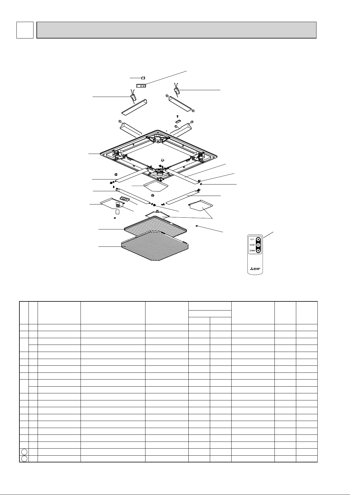
RoHS PARTS LIST
PANEL PARTS
PLP-6BA
PLP-6BAJ
14
1
3
15
16
14
2
9
2
4
10
2
2
5
6
7
11
4
13
12
8
Part numbers that are circled are not shown in the illustration.
No.
1
2
3
4
5
6
7
8
9
10
11
12
13
14
15
16
17
18
Parts No. Parts Name
RoHS
G
S70 E20 003
G
S70 E20 002
G
S70 E30 638
G
S70 E40 638
G
S70 E20 638
G
S70 E20 317
G
S70 E50 658
G
S70 E20 500
G
S70 E20 691
G
S70 E30 691
G
S70 E00 223
G
S70 E00 063
G
S70 E00 040
G
S70 E01 040
G
S70 E60 714
G
S70 0B0 213
G
S70 0B6 310
G
S70 0B0 512
G
S70 E20 305
G
S70 E20 673
AIR OUTLET GRILLE
VANE ASSY
CORNER PANEL (L
CORNER PANEL (L
CORNER PANEL
WIRELESS ADAPTER
RECEIVER
L. L. FILTER-A
GRILLE ASSY
GRILLE ASSY
STEPPING MOTOR
VANE BUSH-A
GEAR(Vane
GEAR(S/M
REMOTE CONTROLLER
MOTOR BOX
CONTROLLER BOARD
LIMIT SWITCH
CABLE ASSY
SCREW ASSY
)
)
)
)
Specification
Q'ty/unit
PLP-6
BA BAJ
11
44
1
1
33
1W.B
1RU
11
1
1
44 MV
88
44
44
1
2
1
1
1
11
Remarks
(
Drawing No.
for Auto Grille
for W.B.
Accessory
)
Wiring
Diagram
Symbol
UK1
U.B
LS1
Recommended
Q'ty
2
Page 3
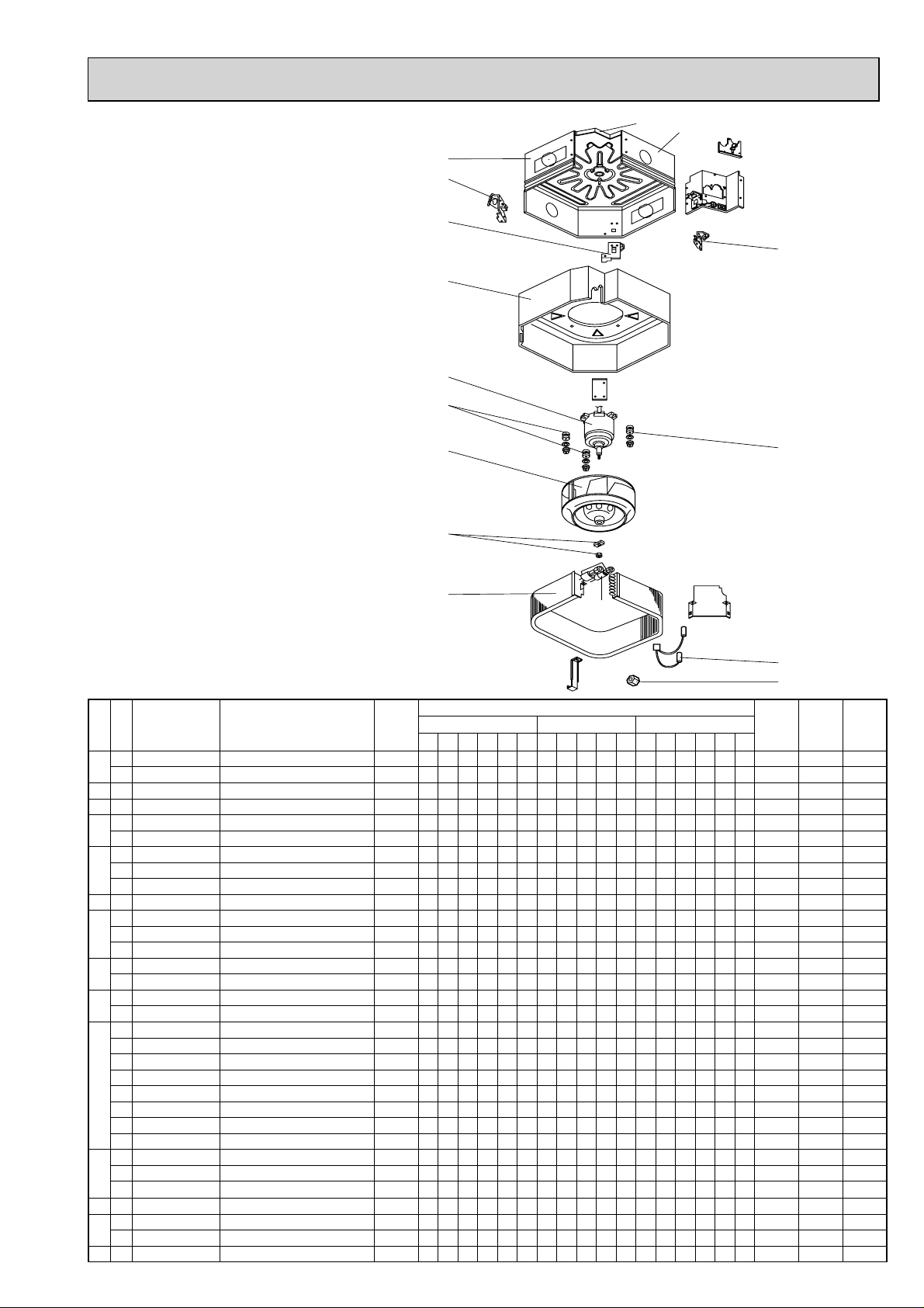
STRUCTIONAL AND FUNCTIONAL PARTS
PLFY-P32VBM-E.UK
PLFY-P40VBM-E.UK
1
2
PLFY-P50VBM-E.UK
PLFY-P63VBM-E.UK
3
PLFY-P80VBM-E.UK
PLFY-P100VBM-E.UK
4
PLFY-P125VBM-E.UK
PLFY-P32VBM-E
PLFY-P40VBM-E
1.UK
1.UK
PLFY-P50VBM-E1.UK
PLFY-P63VBM-E1.UK
PLFY-P80VBM-E1.UK
5
6
PLFY-P32VBM-ER2.UK
PLFY-P40VBM-ER2.UK
7
PLFY-P50VBM-ER2.UK
PLFY-P63VBM-ER2.UK
PLFY-P80VBM-ER2.UK
PLFY-P100VBM-ER2.UK
8
PLFY-P125VBM-ER2.UK
14
13
2
6
10
No.
1
2 G S70 0B2 130 LEG 1A 22222222222222222
3 G S70 0B1 130 LEG 1B 11111111111111111
4
5
6 G S70 0B1 105 MOTOR MOUNT 33333333333333333
7
8
9
10
11
12 G S70 0B2 202 THERMISTOR 11111111111111111
13
14 G S70 0B1 687 BASE 11111111111111111
Parts No. Parts Name
RoHS
G S70 0B3 688 DRUM 2 ASSY 11111 1111111111
G S70 0B4 688 DRUM 2 ASSY 1 1
G S70 0B1 659 INNER COVER ASSY - S 11111 1111111111
G S70 0B2 659 INNER COVER ASSY - L 1 1
G S70 0B1 762 FAN MOTOR 11111 MF
G S70 0B2 762 FAN MOTOR 1 1 MF
G S70 0B3 762 FAN MOTOR 1 1 1 1111111 MF
G S70 0B1 114 TURBO FAN 11111
G S70 0B2 114 TURBO FAN 1 1
G S70 0B3 114 TURBO FAN 1 1 1 1111111
G S70 08K 097 SPL WASHER/NUT M8 111111 1
G S70 10B 097 SPL WASHER/NUT M6 1 1 1 1111111
G S70 0B1 401
G S70 0B2 401
G S70 0C1 480 HEAT EXCHANGER 1 1 1
G S70 0C2 480 HEAT EXCHANGER 1 1 1
G S70 0C3 480 HEAT EXCHANGER 1 1
G S70 0C4 480 HEAT EXCHANGER 1 1 1
G S70 0C5 480 HEAT EXCHANGER 1 1 1
G S70 0C6 480 HEAT EXCHANGER 1
G S70 0C7 480 HEAT EXCHANGER 1
G S70 0C8 480 HEAT EXCHANGER 1
G S70 E17 097 FLARE NUT 3/8" 1 1 1 1 1 1
G S70 E15 097 FLARE NUT 5/8" 1 1 1 1 1
G S70 E16 097 FLARE NUT 3/4" 1 1
G S70 0B1 688 DRUM 1 ASSY 11111 1111111111
G S70 0B2 688 DRUM 1 ASSY 1 1
LINER EXPANSION VALVE
LINER EXPANSION VALVE
Specifi -
PLFY-P·VBM-E.UK
cation
32 40 50 63 80
1111 1111 1111 LEV
PLFY-P·VBM-E1.UK
100
32 40 50 63 80 32 40 50 63 80
125
1 1 1 1 1 LEV
9
Q'ty/unit
PLFY-P·VBM-E2.UK
100
125
Remarks
(Drawing
No.)
33
12
11 Flare nut
Wiring
Daigram
Symbol
TH22/TH23
Recommended
Q'ty
Page 4

FUNCTIONAL AND ELECTRICAL PARTS
PLFY-P32VBM-E.UK
PLFY-P40VBM-E.UK
PLFY-P50VBM-E.UK
PLFY-P63VBM-E.UK
PLFY-P80VBM-E.UK
PLFY-P100VBM-E.UK
PLFY-P125VBM-E.UK
PLFY-P32VBM-E
PLFY-P40VBM-E
1.UK
1.UK
PLFY-P50VBM-E1.UK
PLFY-P63VBM-E1.UK
PLFY-P80VBM-E1.UK
PLFY-P32VBM-ER2.UK
PLFY-P40VBM-ER2.UK
PLFY-P50VBM-ER2.UK
PLFY-P63VBM-ER2.UK
5
4
PLFY-P80VBM-ER2.UK
PLFY-P100VBM-ER2.UK
12
PLFY-P125VBM-ER2.UK
1
14
2
13
12
11
10
3
2
15
9
16
8
No.
1
2
3
4
5
6
7
8
9
10
11
12
13
14
15
16
G
G
G
G
G
G
G
G
G
G
G
G
G
G
G
G
G
Parts No. Parts Name
RoHS
S70 0B2 529
S70 0B6 501
S70 B02 716
S70 0B4 716
S70 512 716
S70 0B5 310
S70 0B4 310
S70 29H 523
S70 0B1 527
S70 0B1 266
S70 0B1 533
S70 0B1 355
S70 0B2 502
S70 A41 524
S70 0B1 663
S70 0B1 313
S70 0B1 202
DRAIN PAN
ELECTRICAL CONTROL BOX
TERMINAL BLOCK
TERMINAL BLOCK
TERMINAL BLOCK
INDOOR CONTROLLER BOARD
INDOOR CONTROLLER BOARD
DRAIN SOCKET
DRAIN HOSE ASSY
DRAIN SENSOR (Float Switch)
DRAIN SENSOR HOLDER
DRAIN PUMP
BELLMOUTH
DRAIN PLUG
CORNER COVER
ADDRESS BOARD
ROOM TEMP. THERMISTOR
RS SBA
7
6
Qty/unit
Specification
3P (M1,M2,S) TB4
3P (L, N, )TB2
2P (1,2) TB15
PLFY-P·VBM-E(1).UK
32/40/50/63/80/100/125
1
1
1
1
1
1
1
1
1
1
1
1
1
1
1
1
PLFY-P·VBM-ER2.UK
32/40/50/63/80/100/125
1
1
1
1
1
1
1
1
1
1
1
1
1
1
1
1
Remarks
(Drawing
No.)
ACCESSORY
Wiring
Diagram
Symbol
I.B
I.B
FS
DP
A.B
TH21
Recommended
Q'ty
4
Page 5

2
2-1. OPTIONAL PARTS LIST
2-1-1. MULTI FUNCTION CASEMENT
OPTIONAL PARTS
Part No.
2-1-2. AIR OUTLET SHUTTER PLATE
Part No. PAC-SH51SP-E
2-1-3. HIGH EFFICIENCY FILTER (PAC-SH53TM-E is required in using this optional part.)
Part No. PAC-SH59KF-E
2-1-4. i-SEE SENSOR CORNER PANEL
Part No. PAC-SA1ME-E
2-1-5. AUTOMATIC FILTER ELEVATION PANEL
Part No. PLP-6BAJ
2-1-6. SPACE PANEL
PAC-SH53TM-E
Part No.
2-1-7. FLANGE FOR FRESH AIR INTAKE
Part No.
2-1-8. WIRELESS SIGNAL RECEIVER (CORNER PANEL)
Part No.
2-1-9. WIRELESS REMOTE CONTROLLER
Part No.
2-1-10. WIRED REMOTE CONTROLLER (MA REMOTE CONTROLLER)
Part No.
2-1-11. WIRED REMOTE CONTROLLER (ME REMOTE CONTROLLER)
PAC-SH48AS-E
PAC-SH65OF-E
PAR-SA9FA-E
PAR-FL32MA
PAR-21MAA
Part No.
2-1-12. DECORATION PANEL
Part No.
PAR-F27MEA
PLP-6BA
5
Page 6

2-2. AUTOMATIC FILTER ELEVATION PANEL
2-2-1. OPERATION (AUTOMATIC FILTER ELEVATION PANEL: PLP-6BAJ)
(1) Normal operation
UP/DOWN
Air intake grille is raised/lowered by
instructions of “UP” and “DOWN”.
Air intake grille does not move under the
UP/DOWN
Machine 1
state of no-load detection or obstacle detection.
Air intake grille stops automatically at the set lowering
distance from the ceiling level.
STOP
It stops in the cases below :
Detection
switch
• When it reaches at the set lowering distance from
the ceiling level.
It automatically stops based on the calculation at
distance from the time taken to lower.
• When it is stored in the panel.
Wire 1a
Air intake grille is judged to be stored in the panel
when storage detection switch is pressed for 3 seconds continuously.
• When receiving instructions of “STOP”, “DOWN” while moving up and “UP” while moving down.
“STOP” button is only for the remote controller for Automatic Filter Elevation Panel.
As for wired remote controller, it takes several seconds to stop due to transmission speed.
• When both wire 1b and wire 2b are no-loaded.
Only the wire b in each UP/DOWN Machine has tension detection switch.
(2) Special operation
Re-storing operation
Case : Catch of grille or malfunction of storage detection switch
Re-storing operation will be done when storage detection switch is not pressed with air intake grille raised
by the set distance. And operation below will be repeated up to 4 times.
10cm down 30cm up ···· 10cm down 30cm up
No-load detection
Case : “UP/DOWN” instruction without grille.
When both wire 1b and wire 2b are no-loaded, grille does not move.
Obstacle detection
Case : Making contact with something while lowering.
When both wire 1b and wire 2b are no-loaded by making contact with something while lowering, it stops and
is raised by 10cm and stops again.
Wire 1b
Wire 2a
Fig.1
UP/DOWN
Machine 2
Wire 2b
[Emergency operation]
• When the wireless remote controller cannot be used (in the case of battery discharge, misplacing of the wireless
remote controller, malfunctioning and so on), the emergency switch on the sensor can be used as an alternative.
* When doing this, particular caution must be taken not to fall.
To lower the air intake grille : Press the button once.
(For emergency heating operation, press this button.)
To raise the air intake grille : Press the button once.
(For emergency cooling operation, press this button.)
• To stop the air intake grille from moving, use the opposite buttons to those used to initiate movement.
(To stop it from lowering, press the “UP” button; To stop it from rising, press the “Down” button.)
• When up/down machine is out of order, fix air intake grille temporarily and indoor can be operated.
+ For details, refer to installation manual for grille.
SW22 (Lowering distance Set Up)
Lowering distance
Rough Indication of
the Ceiling Height
Configuration
Lowering distance
Rough Indication of
the Ceiling Height
Configuration
1.2 m
- 2.4 m 2.4 m - 2.8 m 2.8 m - 3.2 m 3.2m - 3.6m
ON
OFF
123456789
2.8 m 3.6 m
3.6 m - 4.0 m 4.0 m - 4.4 m 4.4 m - 4.8 m 4.8 m - 5.2 m
ON
OFF
123456789
Lowering distance
Rough Indication of
the Ceiling Height
Configuration
10
Lowering distance
Rough Indication of
the Ceiling Height
Configuration
10
1.6 m (Initial setting)
ON
OFF
123456789
3.2 m 4.0 m
ON
OFF
123456789
Lowering distance
Rough Indication of
the Ceiling Height
Configuration
10
Lowering distance
Rough Indication of
the Ceiling Height
Configuration
10
2.0 m
ON
OFF
123456789
ON
OFF
123456789
Lowering distance
Rough Indication of
the Ceiling Height
Configuration
10
Lowering distance
Rough Indication of
the Ceiling Height
Configuration
10
ON
OFF
123456789
ON
OFF
123456789
2.4 m
10
10
6
Page 7

2-2-2. ELECTRICAL CIRCUIT
(1) Wiring diagram (Panel)
UK1
UK1
LS21
MU1
LS21
MU1
Panel
FUSE
R
E
D
3
W.B
CNB
1
(WHT)
2
BZ
3
4
SW1
5
6
7
SW2
8
RU
9
B
R
L
E
K
D
11325
U.B
GRN/YLW
LS1
2
1
WHT
2
WHT
1
WHT
WHT
BLK
BLK
CN2G
(BLK)
CN2F
(BLK)
1
1
ON
2
2
SW22
123456789
1
CN2E
(RED)
B
O
Y
R
R
L
N
N
W
CN3G
3
(BLK)
2
CN2B
CN2C
(WHT)
(WHT)
1
1
B
10
L
K
2
2
R
E
D
CN3A
B
R
(RED)
L
E
K
D
Indoor unit
9
I.B
CNAC
(WHT)
CN22
(BLU)
CN90
(WHT)
Symbol Name Symbol Name
U.B Auto grille controller board W.B Wireless remote controller board
FUSE Fuse (3.15A)
BZ Buzzer
RU Receiver
SW22 switch (Lowering distance set up) SW1 Emergency switch (heating/down)
UK1 Up/down machine SW2 Emergency switch (cooling/up)
MU1 Motor (Up/down) LS1 Limit switch (storage detection)
LS21 Limit switch (tension detection) R.B Wired remote controller
I.B Indoor controller board
CN3G
(BLK)
TB5
11
22
TB6
R.B
(2) Check point of trouble
<LED display>
Turn OFF : No power supply
Blink : Storage detection switch ON (short)
One blink : Storage detection switch OFF (open)
Two blinks : Tension detection switch OFF (open)
<controller board>
Check item Check point Normal Remarks
Up/down controller
P.C. board supply
voltage
Up/down machine
supply voltage
CN3A
(between 3-5)
AC198~264V
CN2B,CN2C DC10~12V
Check when instructing up/down with LED
blinking once.
<Up/down machine>
Check item Check point Normal Check contents
Storage detection
switch
Tension detection
switch
Motor CN2B,CN2C 5~20 Check if it is not open or short.
Entwining wires Pull wire
CN2E open or short
Check if it is short when pressing push switch.
CN2F,CN2G open or short Check if it is short when wire b is tensioned.
Retension :
about 2kgf
Check if wire is drawn out by pulling with 3kgf.
7
Page 8

2-2-3. Troubleshooting
• Check the following points.
Problem Possible Reason Corrective Action
Air intake grille does not
function with operation of the
wireless remote controller.
Air intake grille cannot be
fixed in place.
Air-conditioner is running. Stop running the air-conditioner and try again.
Power failure
Batteries are not inserted into the wireless remote controller.
After recovering from power failure, try again.
Install or replace the battery.
Or battery power is running low.
There is something on the air intake grille.
Or something is stuck in the air intake grille.
Remove the objects or obstacles from the
air intake grille.
Or, remove the stuck object.
There is something on the air intake grille.
Remove the objects or obstacles from the
air intake grille.
Filter is not properly installed.
Lower the air intake grille again and check
whether the filter is installed in the correct
position.
Air intake grille stops lowering.
(Air intake grille would not
lower any further.)
Noises are made during
up/down operation.
(While air intake grille is
moving up/down.)
Noises are made while putting
the air intake grille into place.
Air intake grille repeats rising
and lowering several times
while being put into place.
Air intake grille leans toward
one side during the up/down
operation.
Air intake grille is not hung with all 4 hooks.
The air intake grille has finished lowering to the auto-stop
position.
This is the noise made when the wire is wound and
unwound.
This is the operational noise for putting the air intake
grille into place.
This is the operation for putting the air intake grille into
place.
The speeds of winding/unwinding wires are slightly
different for each wire.
Lower the air intake grille again and hook
on the air intake grille.
This is normal.
This is normal.
HEAD OFFICE : TOKYO BLDG., 2-7-3, MARUNOUCHI, CHIYODA-KU, TOKYO 100-8310, JAPAN
cCopyright 2007 MITSUBISHI ELECTRIC ENGINEERING CO., LTD.
Distributed in Feb. 2009 No. OCB413 REVISED EDITION-B PDF 6
Distributed in Oct. 2007 No. OCB413 REVISED EDITION-A PDF 7
Distributed in Mar. 2007 No. OCB413 PDF 7
Made in Japan
New publication, effective Feb. 2009
Specifications subject to change without notice
 Loading...