

Mitsubishi PLFY-P12NAMU-E, PLFY-P30NAMU-E, PLFY-P15NAMU-E, PLFY-P36NAMU-E, PLFY-P18NAMU-E Technical & Service Manual
...
SPLIT-TYPE, HEAT PUMP AIR CONDITIONERS
TECHNICAL & SERVICE MANUAL
R410A / R22
August 2006
No. OC340
REVISED EDITION-A
[Models]
PLFY-P12NAMU-E
PLFY-P15NAMU-E
PLFY-P18NAMU-E
PLFY-P24NAMU-E
PLFY-P30NAMU-E
PLFY-P36NAMU-E
INDOOR UNIT
Revision:
• RoHS PARTS LISTis added.
• Some descriptions have been
modified.
• Please void OC340.
NOTE:
• This manual describes only
service data of the indoor
units.
• RoHS compliant products have
<G> mark on the spec name
plate.
• For servicing of RoHS compli-
ant products, refer to the RoHS
PARTS LIST.
CONTENTS
1. FEATURES ····························································· 2
2. PART NAMES AND FUNCTIONS ························· 3
3. SPECIFICATIONS·················································· 5
4. 4-WAY AIR FLOW SYSTEM ·································· 8
5. OUTLINES AND DIMENSIONS····························· 11
6. WIRING DIAGRAM ················································ 12
7.
REFRIGERANT SYSTEM DIAGRAM
8. MICROPROCESSOR CONTROL·························· 14
9. TROUBLE SHOOTING ·········································· 21
10. DISASSEMBLY PROCEDURE ······························ 26
11. PARTS LIST ··························································· 29
12. RoHS PARTS LIST ················································ 32
13. OPTIONAL PARTS················································· 35
······················· 13
1
33-7/16
Unit:in.
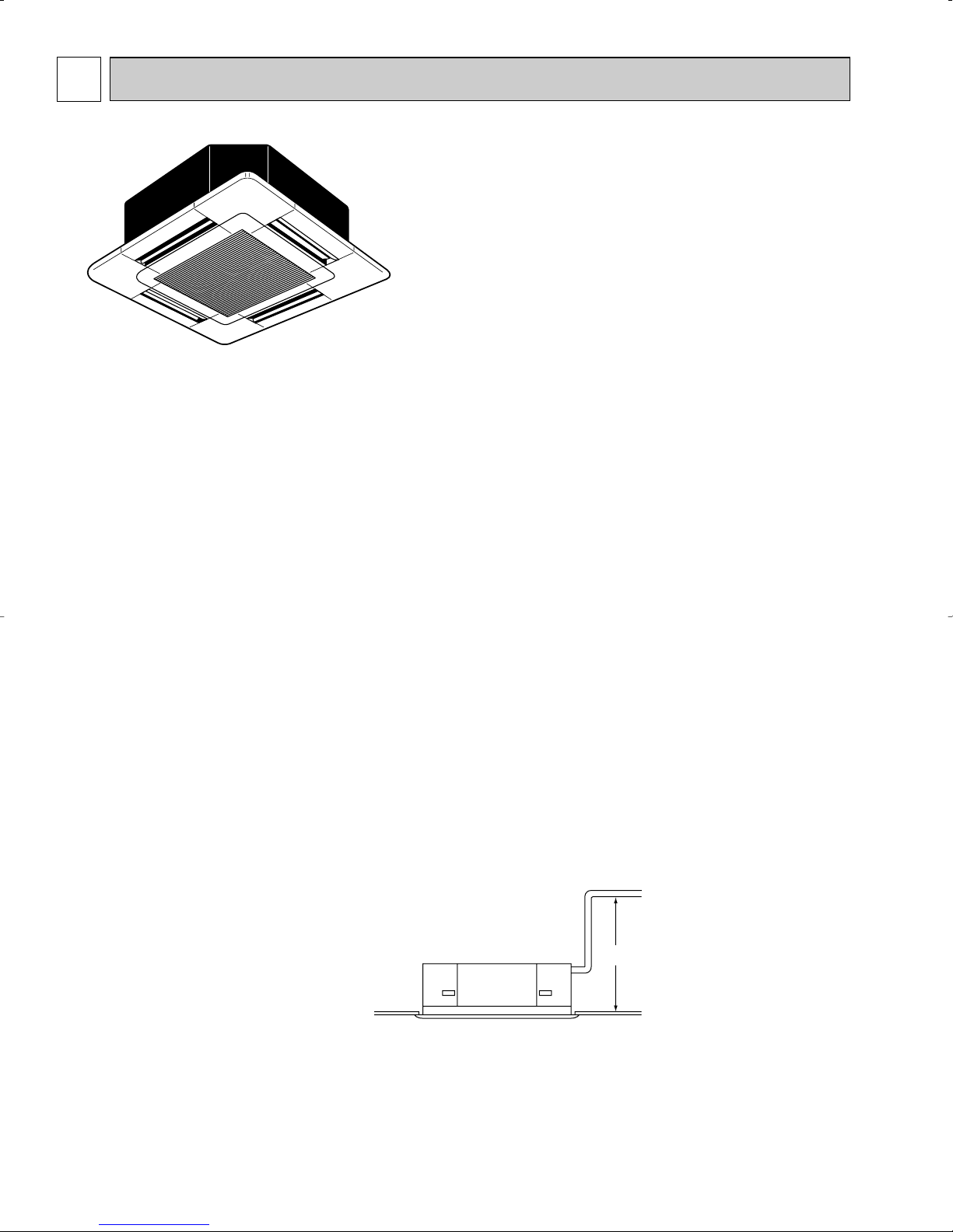
FEATURES
Indoor Unit
Models Cooling capacity / Heating capacity
PLFY-P12NAMU-E 12,000 / 13,500 Btu/h
PLFY-P15NAMU-E 15,000 / 17,000 Btu/h
PLFY-P18NAMU-E 18,000 / 20,000 Btu/h
PLFY-P24NAMU-E 24,000 / 27,000 Btu/h
PLFY-P30NAMU-E 30,000 / 34,000 Btu/h
PLFY-P36NAMU-E 36,000 / 40,000 Btu/h
1. SPACE-SAVING CENTRALLY LOCATED CEILING RECESSED INSTALLATION
2. 4-WAY AIR FLOW SYSTEM
This series allows you to select from 2, 3, and 4 way air flow directions according to your requirement. As a result, you get
superb flexibility in choosing a configuration that gives you maximum cooling/heating efficiency in a neat and unobstructive
installation.
3. DRAIN PUMP FOR EASY PIPE CONNECTION (DRAIN LIFT-UP MECHANISM)
This mechanism, with its capacity to raise drain water 33-7/16 inch above the ceiling line, is convenient for removing water
and avoiding piping contact with beams, etc.
4. FRESH AIR INTAKE AND BRANCH DUCTING ARE AVAILABLE (on-site work)
5. HIGH RELIABILITY AND EASY SERVICING.
2
2
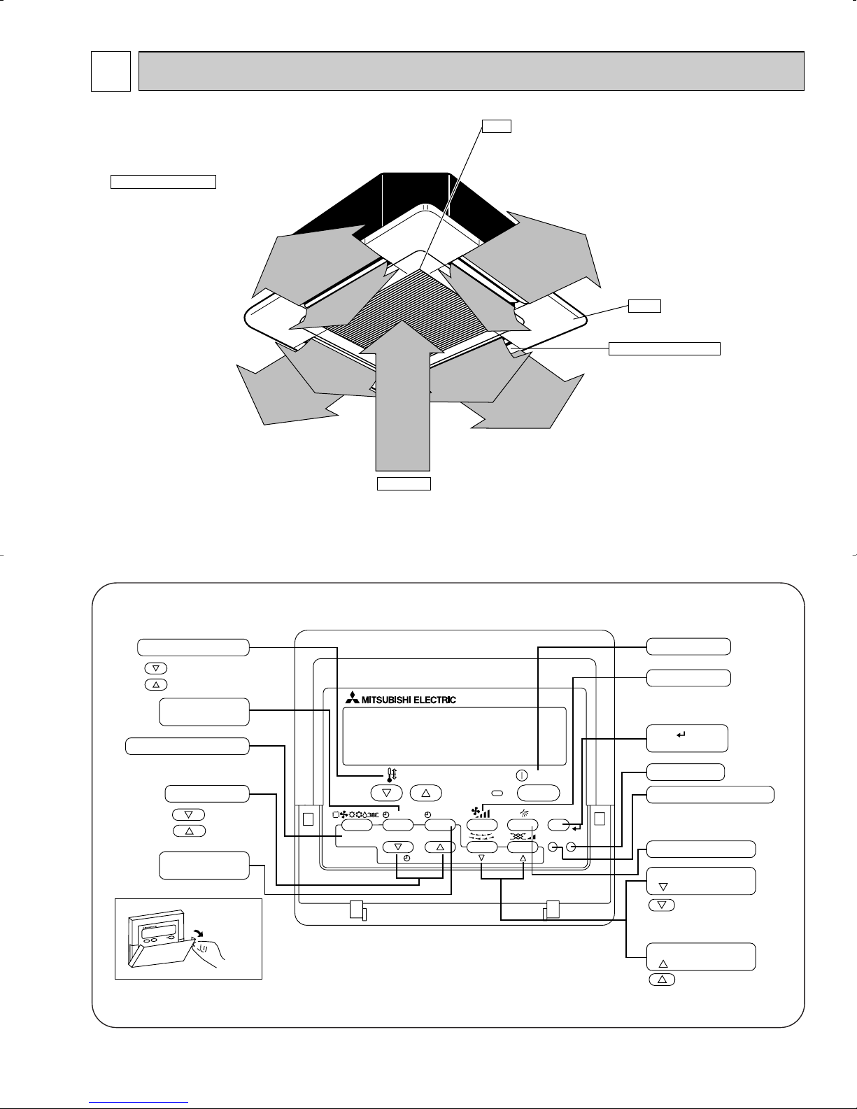
Auto Air Swing Vane
Disperses airflow up and
down and adjusts the angle
of airflow direction.
Grille
Filter
Removes dust and pollutants
from return air
Horizontal Air Outlet
Sets airflow horizontal automatically
during cooling or dehumidifying.
Air Intake
Returns air from room.
PAR-21MAA
ON/OFF
FILTER
CHECK
OPERATION
CLEAR
TEST
TEMP.
MENU
BACK DAY
MONITOR/SET
CLOCK
ON/OFF
Set Temperature buttons
Down
Up
Timer Menu button
(Monitor/Set button)
Mode button (Return button)
Set Time buttons
Back
Ahead
Timer On/Off button
(Set Day button)
Opening the
door.
ON/OFF button
Fan Speed button
Filter button
(<Enter> button)
Test Run button
Check button (Clear button)
Airflow Up/Down button
Louver button
(
Operation button)
To preceding operation
number.
Ventilation button
(
Operation button)
To next operation number.
PART NAMES AND FUNCTIONS
● Indoor (Main) Unit
● Remote controller
● Once the controls are set, the same operation mode can be repeated by simply pressing the ON/OFF button.
● Operation buttons
3
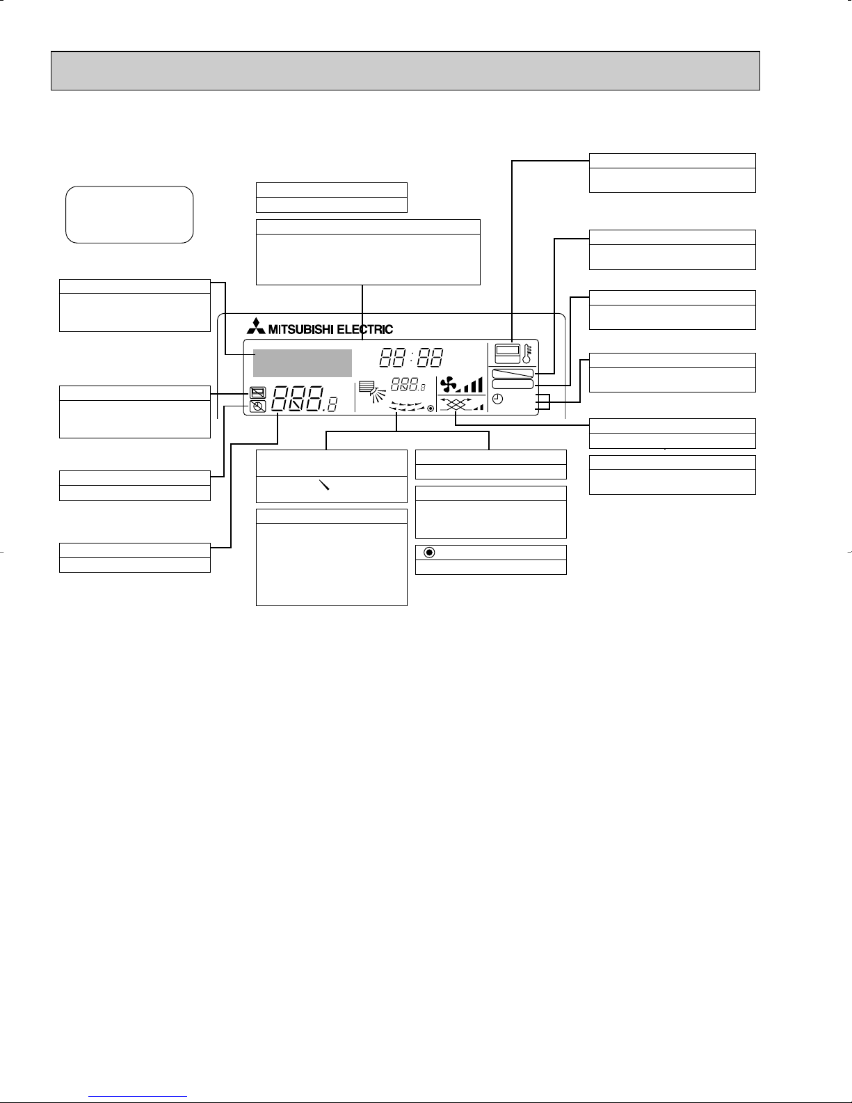
● Display
For purposes of this explanation,
all parts of the display are shown
as lit. During actual operation, only
the relevant items will be lit.
˚F˚C
˚F˚C
ERROR CODE
AFTER
TIMER
TIME SUN MON TUE WED THU FRI SAT
ON
OFF
Hr
AFTER
FILTER
FUNCTION
ONLY1Hr.
WEEKLY
SIMPLE
AUTO OFF
Identifies the current operation
Shows the operating mode, etc.
* Multilanguage display is sup-
ported.
“Centrally Controlled” indicator
Indicates that operation of the remote controller has been prohibited by a master controller.
“Timer Is Off” indicator
Indicates that the timer is off.
Temperature Setting
Shows the target temperature.
Day-of-Week
Shows the current day of the week.
Time/Timer Display
Shows the current time, unless the simple or Auto Off
timer is set.
If the simple or Auto Off timer is set, shows the time
remaining.
“Sensor” indication
Displayed when the remote controller
sensor is used.
“Locked” indicator
Indicates that remote controller buttons have been locked.
“Clean The Filter” indicator
Comes on when it is time to clean the
filter.
Timer indicators
The indicator comes on if the corresponding timer is set.
Up/Down Air Direction indicator
The indicator shows the direction of the outcoming airflow.
“One Hour Only” indicator
Displayed if the airflow is set to
Low and downward during COOL
or DRY mode. (Operation varies
according to model.)
The indicator goes off after one
hour, at which time the airflow direction also changes.
Room Temperature display
Shows the room temperature.
Louver display
Indicates the action of the swing
louver. Does not appear if the
louver is stationary.
(Power On indicator)
Indicates that the power is on.
Fan Speed indicator
Shows the selected fan speed.
Ventilation indicator
Appears when the unit is running in
Ventilation mode.
Caution
● Only the Power on indicator lights when the unit is stopped and power supplied to the unit.
● If you press a button for a feature that is not installed at the indoor unit, the remote controller will display the “Not Available”
message.
If you are using the remote controller to drive multiple indoor units, this message will appear only if the feature is not present at every unit connected.
● When power is turned ON for the first time, it is normal that “PLEASE WAIT” is displayed on the room temperature indication (For max. 2minutes). Please wait until this “PLEASE WAIT” indication disappear then start the operation.
4
3
Item
Btu/h
Btu/h
kW
kW
A
A
—
in
in
in
—
—
CFM
CFM
Pa
kW
—
—
in
in
in
dB
lb
Cooling capacity
Power
Heat exchanger
Insulator
Air filter
Fan ✕ No
Pipe
dimensions
Unit drain pipe size
Noise level W3
Product weight
Exterior
(munsell symbol)
Fan motor
output
External
static pressure
Liquid
side
Gas
side
Heating capacity
F
a
n
Dimensions
Height
Width
Depth
Electric characteristic
Input
Cooling
Heating
Cooling
Heating
Current
PLFY-P12NAMU-E
PLFY-P18NAMU-E PLFY-P24NAMU-E PLFY-P30NAMU-E PLFY-P36NAMU-E
12,000
13,500
0.14
0.14
0.68
0.68
390-420-460-490
350-380-410-440
24-27-28-30
18,000
20,000
0.14
0.14
0.68
0.68
490-530-570-640
470-500-530-600
27-28-31-33
PLFY-P15NAMU-E
15,000
17,000
0.14
0.14
0.68
0.68
420-460-490-570
380-410-470-530
27-28-30-32
30,000
34,000
0.27
0.27
1.30
1.30
710-810-920-990
670-770-870-930
3/8"
34-36-40-41
36,000
40,000
0.27
0.27
1.30
1.30
780-880-990-1060
730-830-930-1000
5/8" / 3/4"
(Compatible)
37-40-43-44
24,000
27,000
0.14
0.14
0.68
0.68
530-570-640-710
500-530-600-670
PVC with O.D.1-1/4"
28-30-33-34
Single phase 208/230V 60Hz
V
·Hz
11-3/4<1-3/16>
0.110
5/8"
53<11>
66<11>
Air flow
W3
DRY
WET
Unit : Galvanized sheets with gray heat insulation Grills : ABS resin Munsell<0.70Y 8.59/0.97>
33-1/16<37-3/8>
33-1/16<37-3/8>
Cross fin
Turbo fan ✕ 1
0
Polyethylene sheet
PP honey comb fabric
10-3/16<1-3/16>
0.070
1/2"
1/4"
49<11>
1/2" / 5/8"
(Compatible)
1/4" / 3/8"
(Compatible)
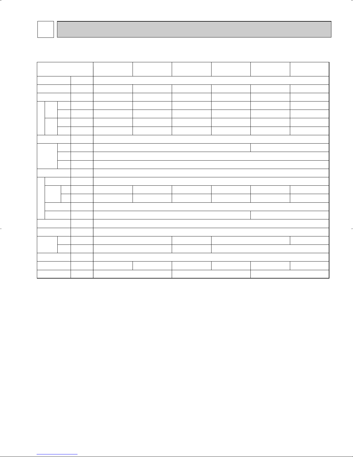
SPECIFICATIONS
3-1. SPECIFICATIONS
Note 1. Rating conditions
Note 2. The number indicated in < > is just for the grille.
W 3. Air flow and the noise level are indicated as Low - Medium2 - Medium1 - High.
Cooling : Indoor : D.B. 80_F W.B. 67_F
Heating : Indoor : D.B. 70_F
outdoor : D.B. 95_F W.B. 75_F
outdoor : D.B. 47_F W.B. 43_F
5
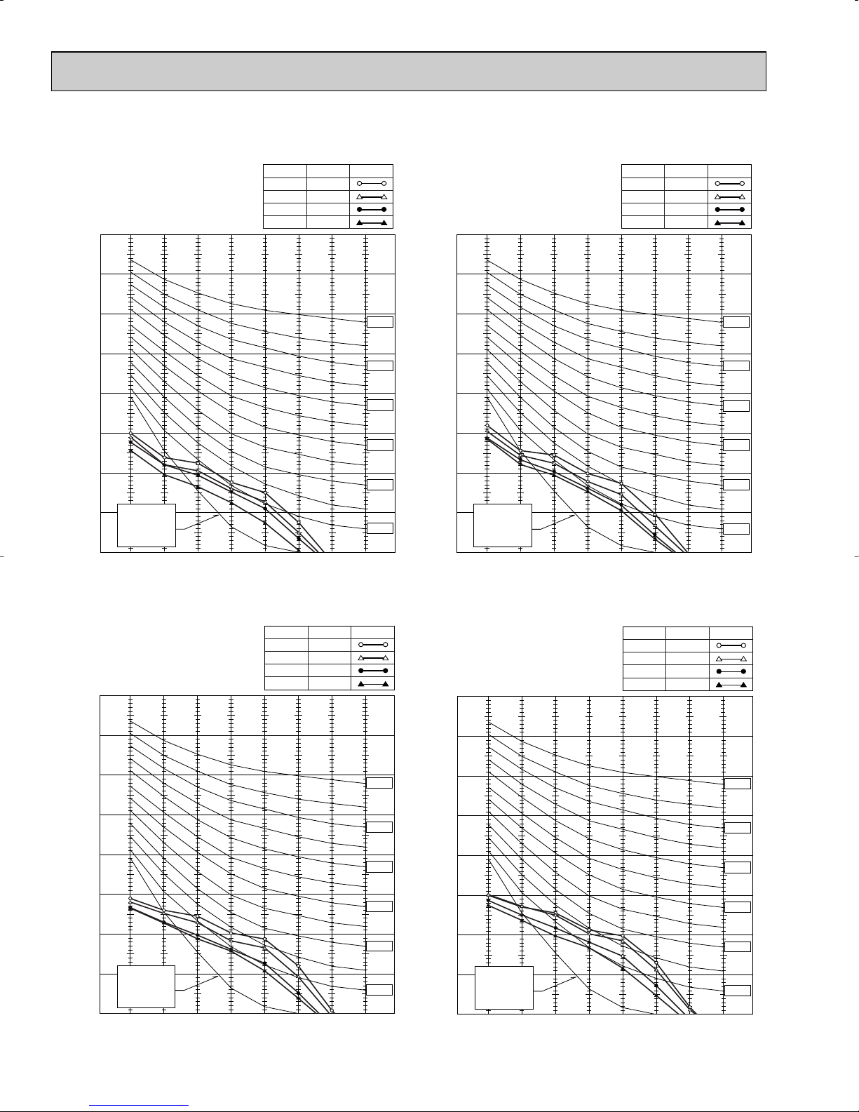
3-2. NOISE CRITERION CURVES
90
80
70
60
50
40
30
20
10
63 125 250 500 1000 2000 4000 8000
APPROXIMATE
THRESHOLD OF
HEARING FOR
CONTINUOUS
NOISE
NC-60
NC-50
NC-40
NC-30
NC-20
NC-70
OCTAVE BAND SOUND PRESSURE LEVEL, dB re 0.0002 MICRO BAR
BAND CENTER FREQUENCIES, Hz
PLFY-P12NAMU-E
High
Medium1
Medium2
Low
NOTCH
30
28
27
24
SPL(dB)
LINE
90
80
70
60
50
40
30
20
10
63 125 250 500 1000 2000 4000 8000
APPROXIMATE
THRESHOLD OF
HEARING FOR
CONTINUOUS
NOISE
NC-60
NC-50
NC-40
NC-30
NC-20
NC-70
OCTAVE BAND SOUND PRESSURE LEVEL, dB re 0.0002 MICRO BAR
BAND CENTER FREQUENCIES, Hz
PLFY-P18NAMU-E
High
Medium1
Medium2
Low
NOTCH
33
31
28
27
SPL(dB)
LINE
90
80
70
60
50
40
30
20
10
63 125 250 500 1000 2000 4000 8000
APPROXIMATE
THRESHOLD OF
HEARING FOR
CONTINUOUS
NOISE
NC-60
NC-50
NC-40
NC-30
NC-20
NC-70
OCTAVE BAND SOUND PRESSURE LEVEL, dB re 0.0002 MICRO BAR
BAND CENTER FREQUENCIES, Hz
PLFY-P24NAMU-E
High
Medium1
Medium2
Low
NOTCH
34
33
30
28
SPL(dB)
LINE
90
80
70
60
50
40
30
20
10
63 125 250 500 1000 2000 4000 8000
APPROXIMATE
THRESHOLD OF
HEARING FOR
CONTINUOUS
NOISE
NC-60
NC-50
NC-40
NC-30
NC-20
NC-70
OCTAVE BAND SOUND PRESSURE LEVEL, dB re 0.0002 MICRO BAR
BAND CENTER FREQUENCIES, Hz
PLFY-P15NAMU-E
High
Medium1
Medium2
Low
NOTCH
32
30
28
27
SPL(dB)
LINE
6
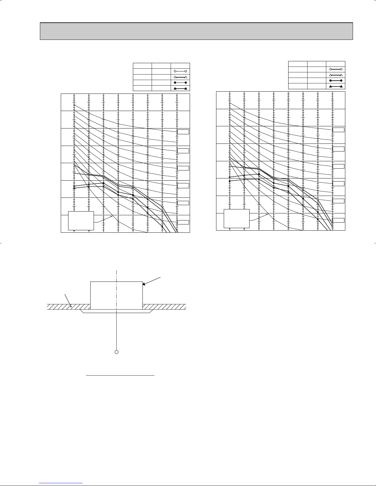
PLFY-P30NAMU-E
90
NOTCH
High
Medium1
Medium2
Low
SPL(dB)
41
40
36
34
LINE
PLFY-P36NAMU-E
90
NOTCH
High
Medium1
Medium2
Low
SPL(dB)
44
43
40
37
LINE
80
70
60
50
40
30
APPROXIMATE
20
THRESHOLD OF
OCTAVE BAND SOUND PRESSURE LEVEL, dB re 0.0002 MICRO BAR
HEARING FOR
CONTINUOUS
NOISE
10
63 125 250 500 1000 2000 4000 8000
BAND CENTER FREQUENCIES, Hz
UNIT
NC-70
NC-60
NC-50
NC-40
NC-30
NC-20
80
70
60
50
40
30
APPROXIMATE
20
THRESHOLD OF
OCTAVE BAND SOUND PRESSURE LEVEL, dB re 0.0002 MICRO BAR
HEARING FOR
CONTINUOUS
NOISE
10
63 125 250 500 1000 2000 4000 8000
BAND CENTER FREQUENCIES, Hz
NC-70
NC-60
NC-50
NC-40
NC-30
NC-20
CEILING
5ft
MICROPHONE
Ambient temperature 80˚F
7
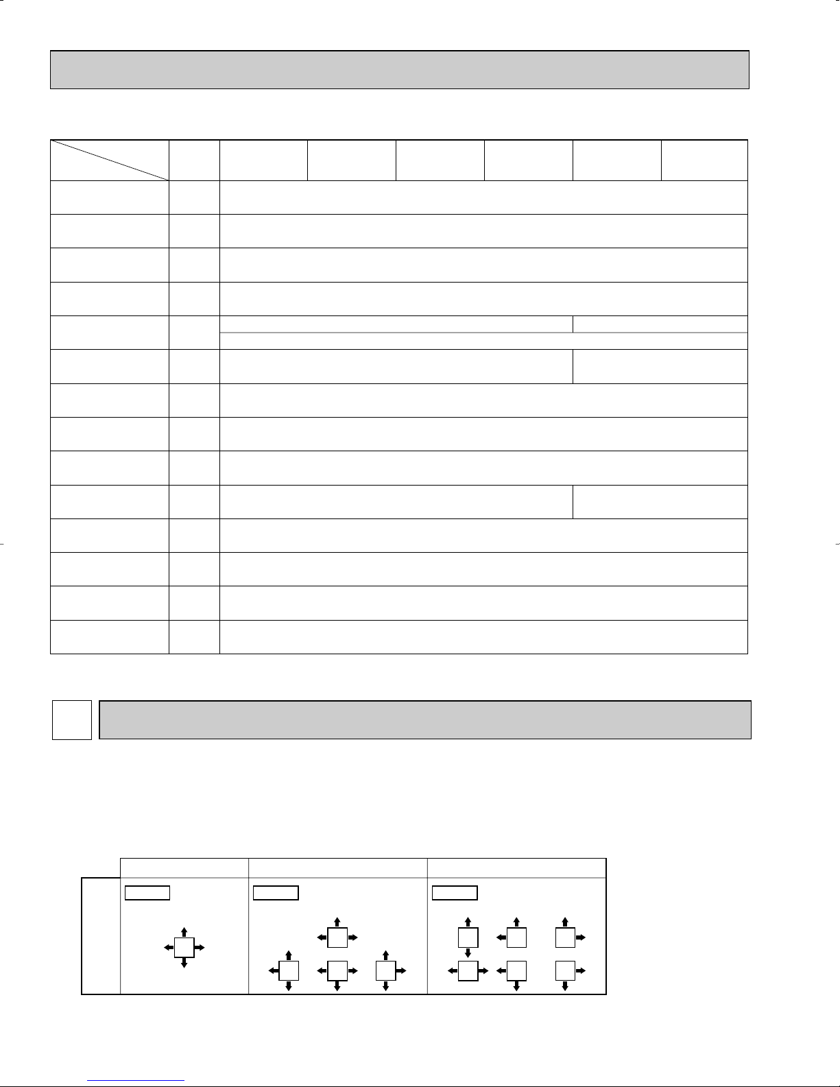
3-3. ELECTRICAL PARTS SPECIFICATIONS
Parts name
Model
Symbol
TH21
TH22
TH23
FUSE
MF
C
MV
DP
DS
LEV
H2
TB2
TB5
TB15
Resistance 30_F/15.8k", 50_F/9.6k", 70_F/6.0k", 80_F/4.8k", 90_F/3.9k", 100_F/3.2k"
Resistance 30_F/15.8k", 50_F/9.6k", 70_F/6.0k", 80_F/4.8k", 90_F/3.9k", 100_F/3.2k"
Resistance 30_F/15.8k", 50_F/9.6k", 70_F/6.0k", 80_F/4.8k", 90_F/3.9k", 100_F/3.2k"
250V 6A
240V 21.8W
(L1, L2, GR) 330V 30A
(M1, M2, S) 250V 20A
(1, 2) 250V 10A
Liquid pipe thermistor
Gas pipe thermistor
Fan motor capacitor
Vane motor
Drain-up mechanism
Drain sensor
Linear expansion valve
PLFY-P12NAMU-E PLFY-P18NAMU-EPLFY-P15NAMU-E PLFY-P24NAMU-E PLFY-P30NAMU-E PLFY-P36NAMU-E
Room temperature
thermistor
Fuse
(Indoor controller board)
Fan motor
(with inner-thermostat)
Electric heater
(Condensation proof)
Power supply terminal
block
Transmission terminal
block
MA remote controller
terminal block
6-pole OUTPUT 110W D176P110MS
Inner-thermostat OPEN 266°F i 9_F
6-pole OUTPUT 70W D17D6P70MS
MSBPC20M13
DC12V 300
"
/phase
PLD-12220ME-2
INPUT 12/10.8W 24R/Hr
Thermistor resistance 30_F/6.3k", 50_F/3.9k", 70_F/2.5k", 80_F/2.0k", 90_F/1.6k", 100_F/1.3k"
DC12V Stepping motor drive port dimension [3.2 (0~2000pulse)
EDM-40YGME
DC12V Stepping motor drive port
dimension [
5.2
(0~2000pulse)
EDM-80YGME
3.0+ ✕ 440V
7.0+ ✕ 440V
Blowout direction
pattern
4-direction<Table 1> 3-direction 2-direction Note1.
For 3 and 2-directional,
please use the air outlet
shutter plate (option).
Pattern 1 Factory setting Pattern 4 One air outlet
fully closed
Pattern 6 Two air outlet
fully closed
4
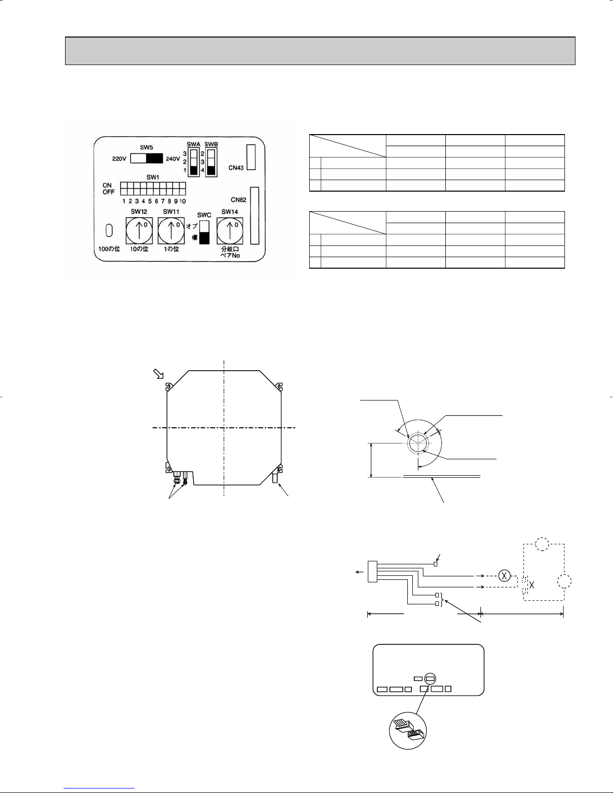
4-1. PLACEMENT OF THE AIR OUTLETS
4-WAY AIR FLOW SYSTEM
• For this grille, the blowout direction comes in 11 patterns.
Also, by setting the dip switches (SWA and SWB) on the address board to the appropriate settings, you can adjust the air
flow and speed. Select the settings from Table according to the location in which you want to install the unit.
1) Decide on the pattern of the airflow direction.
8
1
Standard
8.9
9.8
10.8
2
High ceiling 1
9.8
10.8
11.5
(Unit : feet)
(Unit : feet)
3
High ceiling 2
11.5
11.5
—
4 direction
3 direction
2 direction
SWA
SWB
PLFY-P12, P15, P18NAMU-E
PLFY-P24, P30, P36NAMU-E
4
3
2
1
Standard
10.5
11.8
13.1
2
High ceiling 1
11.8
13.1
13.8
3
High ceiling 2
13.8
13.8
—
4 direction
3 direction
2 direction
SWA
SWB
4
3
2
2) According to the number of air outlets and height of the ceiling to install the unit, be sure to set up the switches
Fresh air intake hole
Fresh air intake hole diagram (Unit : inch)
3 - {1/8
Burring hole
{4-29/32
Burring hole pitch
{3-15/16
(Cut out hole)
Refrigerant pipe Drain pipe
Ceiling surface
120
_
120_
w6-7/32
CN51
Multiple remote
controller adapter
PAC-SA88HA-E
Indoor controller board
Distance between indoor
controller board and relay
must be within 10m.
Be sure to secure insulation
material by tape and such
5
Green
Yellow
Orange
Connector (5P)
Indoor unit side
Multiple remote
controller adapter
PAC-SA88HA-E
Be sure to secure insulation
material by tape and such
Installation at site
CN51
on
indoor unit
board
Red
Brown
1
~
CN51
MB
(SWA, SWB) on the indoor board to the appropriate setting.
• Correspondence of ceiling heights to numbers of air outlets.
(208V)
(230V)
22
11
4-2. FRESH AIR INTAKE (INSTALLATION OF SITE)
• At the time of installation, use the duct holes (cutout) located at the positions shown in following diagram, as and when required.
Note :
Be sure to add5-5/16inch to the dimensions in the diagram that are marked with a “w” if installing a multi function
casement (Option)
4-3. INTERLOCKING OPERATION
METHOD WITH DUCT FAN
(BOOSTER FAN)
• Whenever the indoor unit is operating, the duct fun also
operates.
(1)Connect the optional multiple remote controller
adapter(PAC-SA88HA-E)to the connector CN51 on the
indoor controller board.
(2)Drive the relay after connecting the 12V DC relay
between the Yellow and Orange connector lines.
(w)Use a relay under 1W.
MB: Electromagnetic switch power relay for duct fan.
X: Auxiliary relay (12V DC LY-1F)
9
Static pressure [in. W.G.]
Air flow [CFM]
2.0
50 100 150 200
0.2
0.4
0.6
0.8
0
2 intakes
1 intake
2 intakes
1 intake
Static pressure [in. W.G.]
Air flow [CFM]
2.0
50 100 150 200
0.2
0.4
0.6
0.8
0
Static pressure [in. W.G.]
Air flow [CFM]
2.0
50 100 150 200
0.2
0.4
0.6
0.8
0
Air flow
[CFM]
2 intakes
1 intake
Static pressure [in. W.G.]
2.0
50 100 150 200 250 300
0.2
0.4
0.6
0.8
0
Air flow
[CFM]
2 intakes
1 intake
Static pressure [in. W.G.]
2.0
50 100 150 200 250 300
0.2
0.4
0.6
0.8
0
Air flow [CFM]
Static pressure [in. W.G.]
2.0
50 100 150 200 250 300
0.2
0.4
0.6
0.8
0
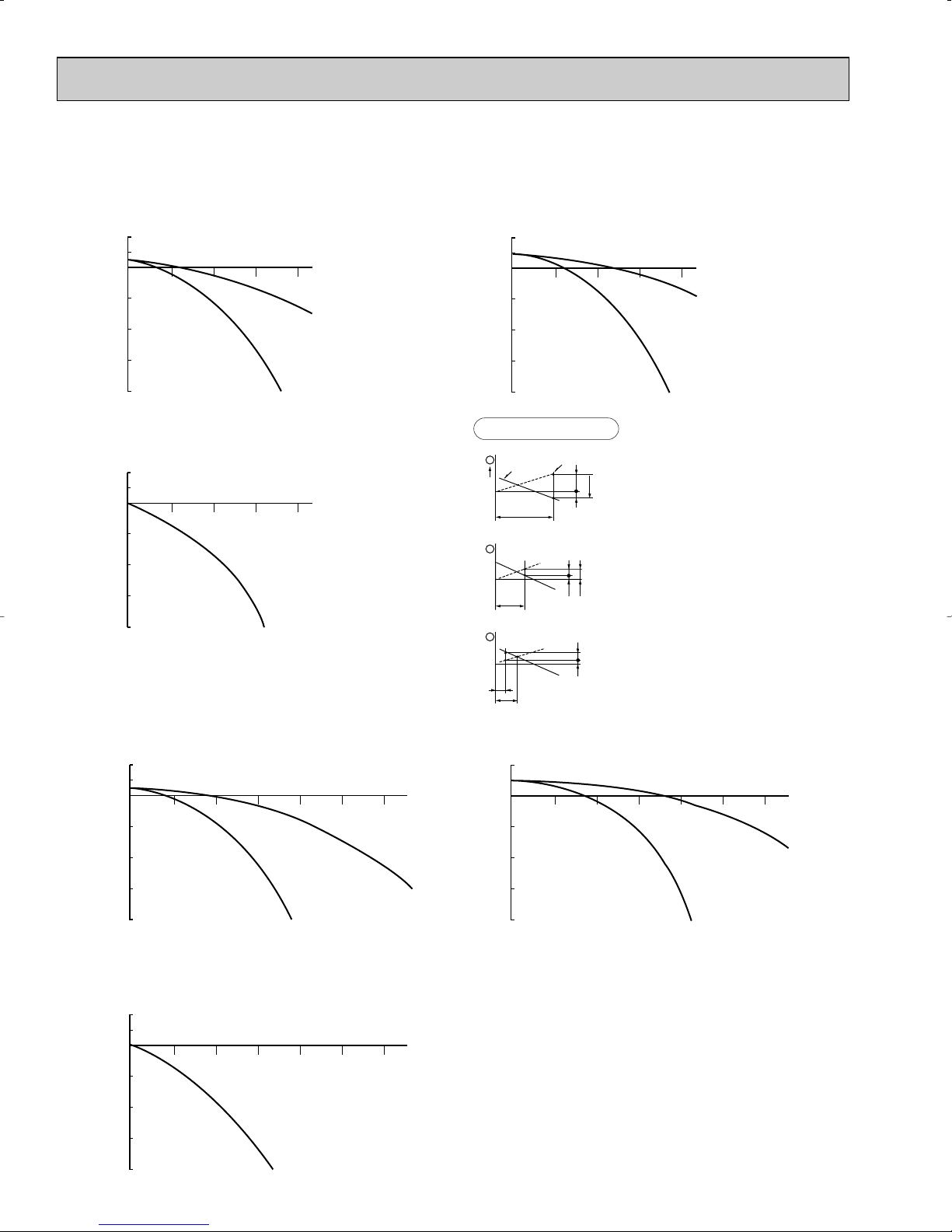
4-4. FRESH AIR INTAKE AMOUNT & STATIC PRESSURE CHARACTERISTICS
Q
0
B
A
C
1
Curve in the
left graphs.
Duct characteristics
at site
Q
A
EC
2
Q
Qa
AD
3
ll
PLFY-P12 /P15 /P18 /P24NAMU-E
Multifunction casement + Standard filter
Multifunction casement + High efficiency filter
Taking air into the unit
22
PLFY-P30 /P36NAMU-E
How to read curves
Q…Planned amount of fresh air intake
A…Static pressure loss of fresh air
intake duct system with air flow
amount Q
B…Forced static pressure at air condi-
tioner inlet with air flow amount Q
C…Static pressure of booster fan with
air flow amount Q
D…Static pressure loss increase
amount of fresh air intake duct system for air flow amount Q
E…Static pressure of indoor unit with air
flow amount Q
Qa…Estimated amount of fresh air
intake with out D <CFM>
Multifunction casement + Standard filter Multifunction casement + High efficiency filter
<CFM>
<in.W.G.>
<in.W.G.>
<in.W.G.>
<in.W.G.>
<in.W.G.>
Taking air into the unit
10
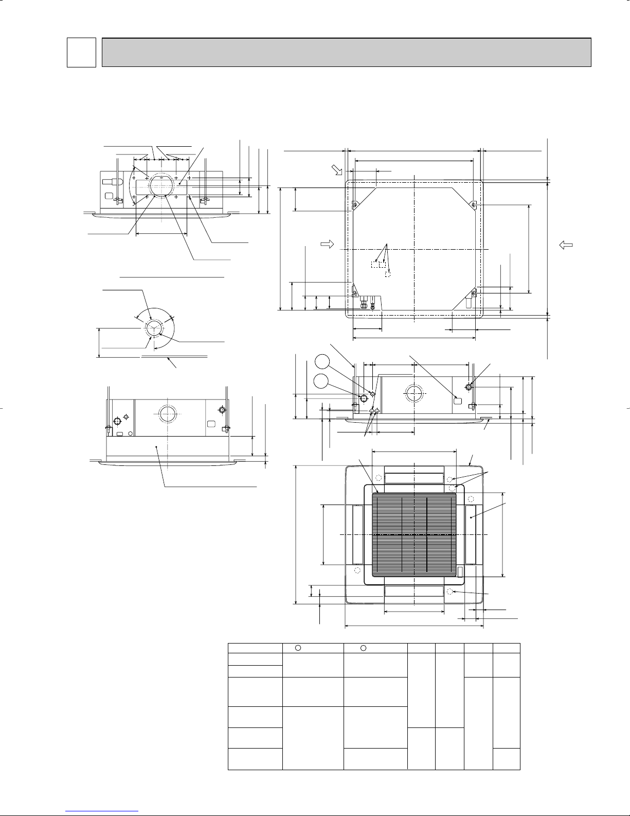
5
OUTLINES AND DIMENSIONS
PLFY-P12NAMU-E PLFY-P24NAMU-E
PLFY-P15NAMU-E PLFY-P30NAMU-E
PLFY-P18NAMU-E PLFY-P36NAMU-E
Branch duct hole
3-15/16(100)
[6-7/8([175)
3-[1/8([2.8)
Burring hole
[4-29/32([125)
6-7/32(158)
3-17/32(90)
3-15/16(100)
°
70
13-25/32(350)
Detail drawing of fresh air intake
120
°
(Cut out hole)
3-17/32(90)
3-15/16(100)
14-[1/8([2.8)
Burring hole
[5-29/32([150)
°
120
[3-15/16([100)
(Cut out hole)
Ceiling surface
High efficiency filter
& Fresh air intake casement(option)
5-1/8(130)
6-3/32(155)
0
+5
5-5/16(135)
0
+3/16
11/16 (17 )
25/32~1-25/32(20~45) 25/32~1-25/32(20~45)
Fresh air intake
6-9/16(167)
Branch duct hole
33-1/16(840)
7-9/16(192)
Suspension
bolt
lower edge
6-1/4(159)
3-27/32(98)
C
Suspension bolt
W3/8(M10)
1
2
6-11/16(170)
5-1/2(140)
(50~70)
1-31/32~2-3/4
6-1/4(159)
D
7-3/4(197)
2-3/8(60)
Wiring entrance holes
1-1/2(37)
Air intake grille
Ceiling hole
33-27/32~35-13/16(860~910)
31-7/8(810)
Suspension bolt pitch
Terminal block
33-1/16(840)
Feeding hole
(Drain pump)
11-1/4(286)
14-23/32(374)
2-[1-1/16(27)
9-3/4(248)1-3/4(45)
22-23/32(577)
Air intake hole
M
6-1/4(159)
Drain pipe
O.D.[1-1/4([32) connection
(VP-25)
Ceiling surface
Grille
Drain hole
M
1(26)
6-1/4(159)
4-1/8(105)
7-15/32(190)
Auto vane
Unit : in(mm)
(20~45)
25/32~1-25/32
Ceiling hole
23-13/16(605)
Suspension bolt pitch
33-27/32~35-13/16(860~910)
(20~45)
25/32~1-25/32
A
B
0
+5
0
+3/16
1-3/16(30)
11/16 (17 )
Branch
duct
hole
Models
PLFY-P12NAMU-E
PLFY-P15NAMU-E
PLFY-P18NAMU-E
PLFY-P24NAMU-E
PLFY-P30NAMU-E
PLFY-P36NAMU-E
37-3/8(950)
3-1/32(77)
2(51)
1 Liquid Pipe
1/4F
([6.35)
1/4F / 3/8F
([6.35/[9.52)
(Compatible)
3/8F
([9.52)
11
16-3/16(411)
Air outlet hole
M
2 Gas Pipe
1/2F
([12.7)
1/2F / 5/8F
([12.7/[15.88)
(Compatible)
5/8F
([15.88)
5/8F / 3/4F
([15.88/[19.05)
(Compatible)
16-3/16(411)
Air outlet hole
37-3/8(950)
A
9-1/2
(241)
11-1/16
(281)
M
Unit : inch (mm)
B
3-11/32
(85)
10-3/16
(258)
3-1/2
(89)
11-3/4
(298)
C
22-23/32(577)
Vane motor
2(51)
3-1/32(77)
D
3
(76)
3-5/32
(80)
3-5/16
(84)
Air intake hole
 Loading...