

Mitsubishi PLFY-P20VCM-E(1), PLFY-P25VCM-E(1), PLFY-P32VCM-E(1), PLFY-P40VCM-E(1) Service Manual
Page 1
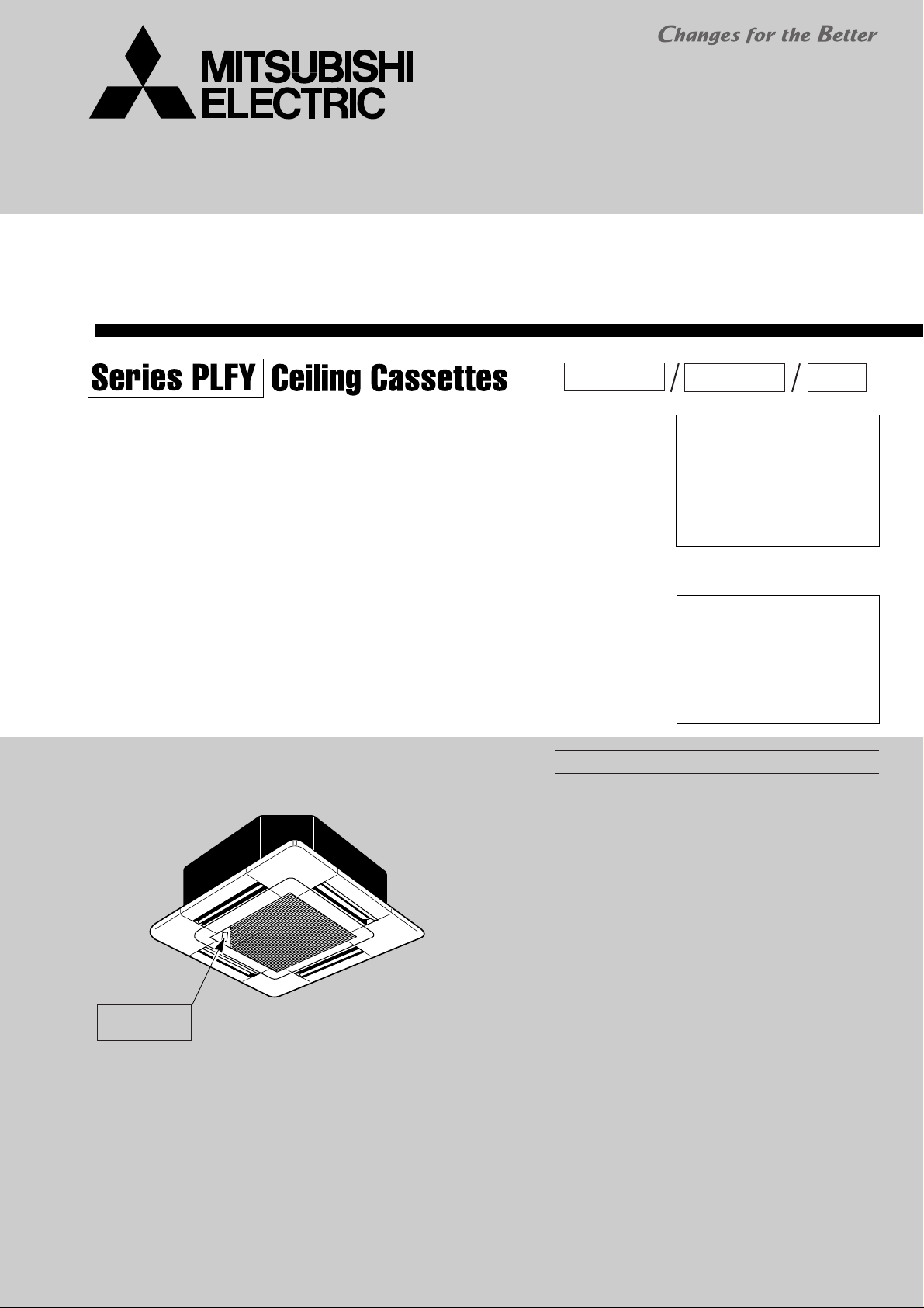
SPLIT-TYPE, HEAT PUMP AIR CONDITIONERS
TECHNICAL & SERVICE MANUAL
July 2007
No.OC314
REVISED EDITION-C
Indoor unit
[Model names] [Service Ref.]
PLFY-P20VCM-E
PLFY-P20VCM-E.TH
PLFY-P20VCM-E1.TH
PLFY-P25VCM-E
PLFY-P25VCM-E.TH
PLFY-P25VCM-E1.TH
PLFY-P32VCM-E
PLFY-P32VCM-E.TH
PLFY-P32VCM-E1.TH
PLFY-P40VCM-E
PLFY-P40VCM-E.TH
PLFY-P40VCM-E1.TH
Model name
indication
INDOOR UNIT
R410A
CONTENTS
1. TECHNICAL CHANGES ·························2
2. SAFETY PRECAUTION··························2
3. PART NAMES AND FUNCTIONS··········6
4. SPECIFICATIONS ···································8
5. 4-WAY AIR FLOW SYSTEM·················10
6. OUTLINES AND DIMENSIONS············12
7. WIRING DIAGRAM·······························13
8.
REFRIGERANT SYSTEM DIAGRAM
9. DISASSEMBLY PROCEDURE·············15
10. TROUBLESHOOTING··························18
11. PARTS LIST··········································25
12. RoHS PARTS LIST·······························29
R407C
Revision :
• PLFY-P20/25/32/40VCME1.TH are added in
REVISED EDITION-C.
• Some descriptions have
been modified.
• Please void OC314
REVISED EDITION-B.
Note :
• RoHS compliant products
have <G> mark on spec
name plate.
For servicing RoHS compliant products, refer to the
RoHS Parts List.
R22
·····14
Page 2
Do not use the existing refrigerant piping.
The old refrigerant and lubricant in the existing piping
contains a large amount of chlorine which may cause the
lubricant deterioration of the new unit.
Use “low residual oil piping”
If there is a large amount of residual oil (hydraulic oil, etc.)
inside the piping and joints, deterioration of the lubricant
will result.
Use ESTR , ETHER or HAB as the lubricant to
coat flares and flange connection parts.
If large amount of mineral oil enters, that can cause
deterioration of refrigerant oil etc.
Use liquid refrigerant to charge the system.
If gas refrigerant is used to seal the system, the composition
of the refrigerant in the cylinder will change and performance
may drop.
Do not use a refrigerant other than R407C.
If another refrigerant (R22, etc.) is used, the chlorine in the
refrigerant may cause the lubricant deterioration.
Use a vacuum pump with a reverse flow check valve.
The vacuum pump oil may flow back into the refrigerant
cycle and cause the lubricant deterioration.
Store the piping to be used during installation
indoors with keep both ends sealed until just
before brazing.
(Store elbows and other joints in a plastic bag.)
If dust, dirt, or water enters the refrigerant cycle,
deterioration of the oil and compressor trouble may result.
Ventilate the room if refrigerant leaks during
operation. If refrigerant comes into contact with
a flame, poisonous gases will be released.
1
TECHNICAL CHANGES
PLFY-P20VCM-E.TH ➔ PLFY-P20VCM-E1.TH
PLFY-P25VCM-E.TH ➔ PLFY-P25VCM-E1.TH
PLFY-P32VCM-E.TH ➔ PLFY-P32VCM-E1.TH
PLFY-P40VCM-E.TH ➔ PLFY-P40VCM-E
• PANEL has been changed.
SLP-2AA(White : 0.70Y 8.59/0.97) ➔ SLP-2AAW(Pure white : 6.4Y 8.9/0.4)
1.TH
2
SAFETY PRECAUTION
CAUTIONS RELATED TO NEW REFRIGERANT
Cautions for units utilizing refrigerant R407C
[1] Cautions for service
·After recovering the all refrigerant in the unit, proceed to working.
·Do not release refrigerant in the air.
·After completing the repair service, recharge the cycle with the specified amount of
liquid refrigerant.
2
Page 3
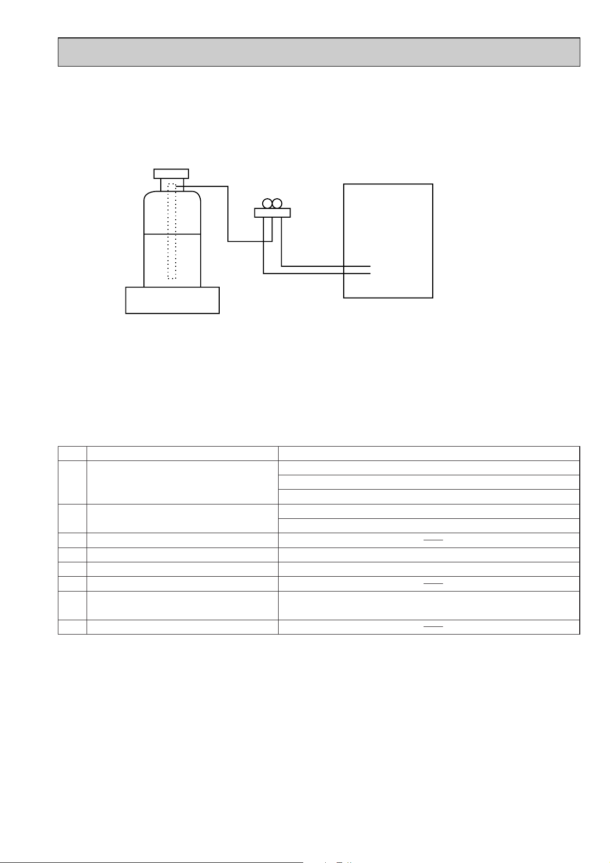
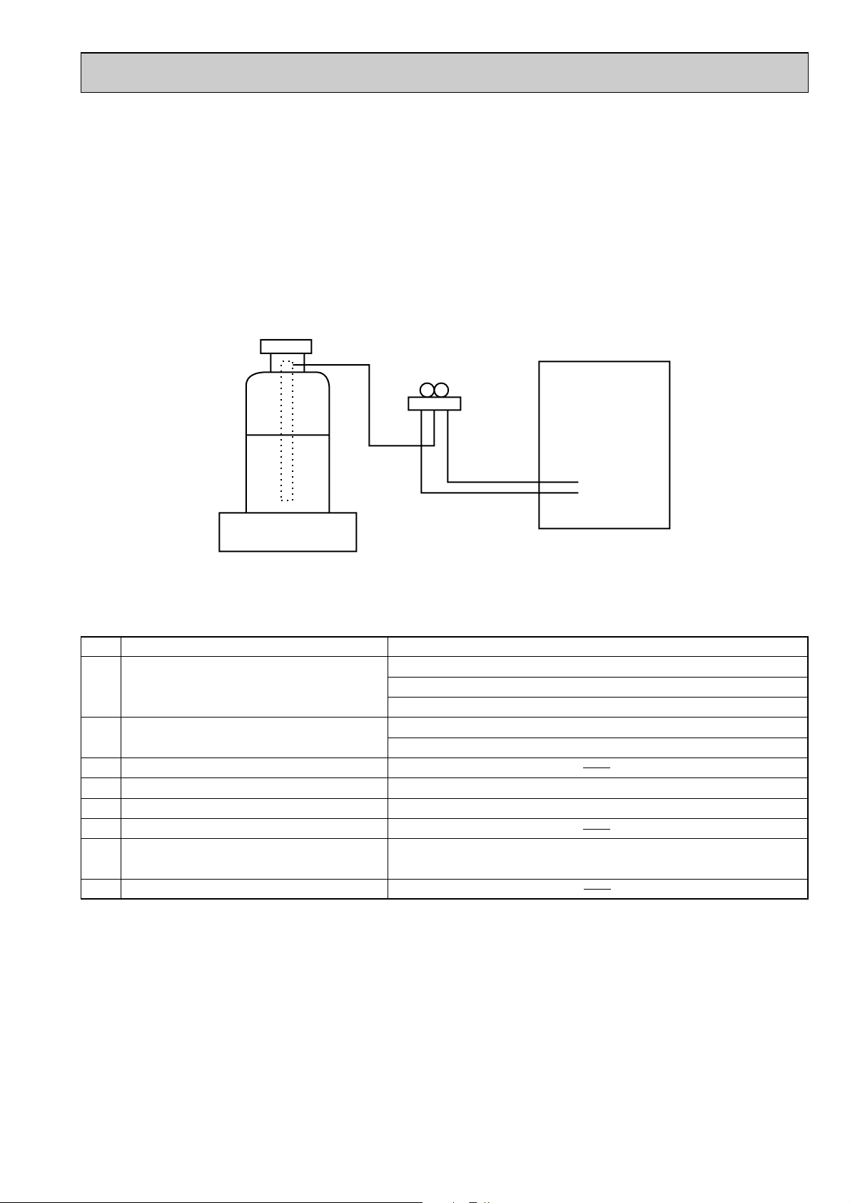
[2] Refrigerant recharging
Gravimeter
Unit
(1) Refrigerant recharging process
1Direct charging from the cylinder
·R407C cylinder which is available on the market has a syphon pipe.
·Leave the syphon pipe cylinder standing and recharge it.
(By liquid refrigerant)
(2) Recharge in refrigerant leakage case
·After recovering all the refrigerant in the unit, proceed to working.
·Do not release the refrigerant in the air.
·After completing the repair service, recharge the cycle with the specified amount of
liquid refrigerant.
[3] Service tools
Use the below service tools as exclusive tools for R407C refrigerant.
No. Tool name Specifications
1 Gauge manifold ·Only for R407C
·Use the existing fitting SPECIFICATIONS. (UNF7/16)
·Use high-tension side pressure of 3.43MPa·G or over.
2 Charge hose ·Only for R407C
·Use pressure performance of 5.10MPa·G or over.
3 Electronic scale
4 Gas leak detector ·Use the detector for R134a or R407C.
5 Adapter for reverse flow check ·Attach on vacuum pump.
6 Refrigerant charge base
7 Refrigerant cylinder ·For R407C ·Top of cylinder (Brown)
·Cylinder with syphon
8 Refrigerant recovery equipment
3
Page 4
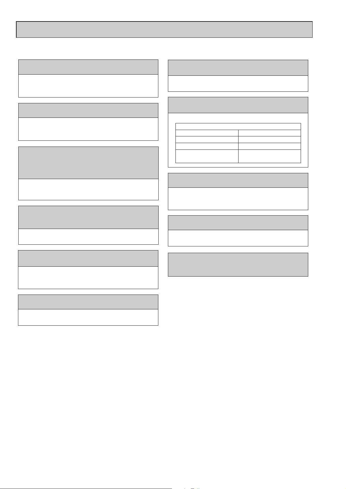
Cautions for units utilizing refrigerant R410A
Store the piping to be used during installation
indoors and keep both ends of the piping sealed
until just before brazing. (Leave elbow joints, etc.
in their packaging.)
Use ester oil, ether oil or alkylbenzene oil (small
amount) as the refrigerant oil applied to flares
and flange connections.
Charge refrigerant from liquid phase of gas
cylinder.
If the refrigerant is charged from gas phase, composition
change may occur in refrigerant and the efficiency will be
lowered.
Do not use refrigerant other than R410A.
If other refrigerant (R22 etc.) is used, chlorine in refrigerant can cause deterioration of refrigerant oil etc.
Use a vacuum pump with a reverse flow check
valve.
Vacuum pump oil may flow back into refrigerant cycle and
that can cause deterioration of refrigerant oil etc.
Use the following tools specifically designed for
use with R410A refrigerant.
The following tools are necessary to use R410A refrigerant.
Keep the tools with care.
If dirt, dust or moisture enters into refrigerant cycle, that can
cause deterioration of refrigerant oil or malfunction of compressor.
Do not use a charging cylinder.
If a charging cylinder is used, the composition of refrigerant will change and the efficiency will be lowered.
Flare tool
Electronic refrigerant
charging scale
Vacuum pump adaptor
Size adjustment gauge
Gauge manifold
Torque wrench
Gas leak detector
Charge hose
Tools for R410A
If dirt, dust or moisture enters into refrigerant cycle, that can
cause deterioration of refrigerant oil or malfunction of compressor.
If large amount of mineral oil enters, that can cause deterioration of refrigerant oil etc.
Do not use the existing refrigerant piping.
The old refrigerant and lubricant in the existing piping
contains a large amount of chlorine which may cause the
lubricant deterioration of the new unit.
Use “low residual oil piping”
If there is a large amount of residual oil (hydraulic oil, etc.)
inside the piping and joints, deterioration of the lubricant
will result.
Ventilate the room if refrigerant leaks during
operation. If refrigerant comes into contact with
a flame, poisonous gases will be released.
4
Page 5
[1] Cautions for service
Gravimeter
Unit
(1) Perform service after recovering the refrigerant left in unit completely.
(2) Do not release refrigerant in the air.
(3) After completing service, charge the cycle with specified amount of refrigerant.
(4) When performing service, install a filter drier simultaneously.
Be sure to use a filter drier for new refrigerant.
[2] Additional refrigerant charge
When charging directly from cylinder
· Check that cylinder for R410A on the market is syphon type.
· Charging should be performed with the cylinder of syphon standing vertically. (Refrigerant is charged from liquid phase.)
[3] Service tools
Use the below service tools as exclusive tools for R410A refrigerant.
No. Tool name Specifications
1 Gauge manifold ·Only for R410A
·Use the existing fitting
·Use high-tension side pressure of 5.3MPa·G or over.
2 Charge hose ·Only for R410A
·Use pressure performance of 5.09MPa·G or over.
3 Electronic scale
4 Gas leak detector ·Use the detector for R134a, R407C or R410A.
5 Adaptor for reverse flow check ·Attach on vacuum pump.
6 Refrigerant charge base
7 Refrigerant cylinder ·Only for R410A ·Top of cylinder (Pink)
·Cylinder with syphon
8 Refrigerant recovery equipment
specifications
. (UNF1/2)
5
Page 6
3
PAR-21MAA
ON/OFF
FILTER
CHECK
OPERATION
CLEAR
TEST
TEMP.
MENU
BACK DAY
MONITOR/SET
CLOCK
ON/OFF
Temperature setting buttons
Down
Up
Timer Menu button
(Monitor/Set button)
Mode button (Return button)
Set Time buttons
Back
Ahead
Timer On/Off button
(Set Day button)
Opening the
lid
ON/OFF button
Fan Speed button
Filter button
(<Enter> button)
Test Run button
Check button (Clear button)
Airflow Up/Down button
Louver button
( Operation button)
T o return operation
number
Ventilation button
( Operation button)
To go to next operation
number
Built-in temperature sensor
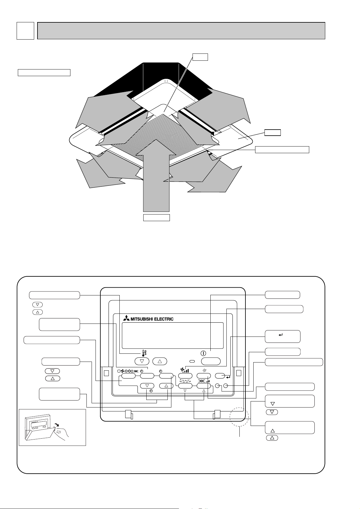
PART NAMES AND FUNCTIONS
● Indoor Unit
Horizontal Air Outlet
Sets horizontal airflow automatically
during cooling or dehumidifying.
Filter
Remove dust and pollutants
from inhaled air.
Grille
Auto Air Swing Vane
Disperses airflow up and
down and adjusts the angle
of airflow direction.
Air Intake
Inhales air from room.
● Wired remote controller
Once the controllers are set, the same operation mode can be repeated by simply pressing the ON/OFF button.
6
Page 7
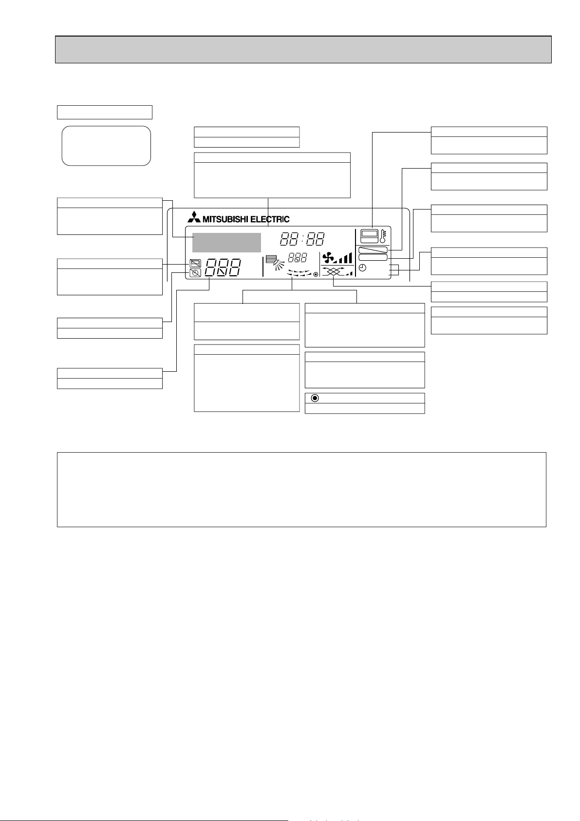
● Wired remote controller
●
●
˚F˚C
˚F˚C
ERROR CODE
AFTER
TIMER
TIME SUN MON TUE WED THU FRI SAT
ON
OFF
Hr
AFTER
FILTER
FUNCTION
ONLY1Hr.
WEEKLY
SIMPLE
AUTO OFF
Note:
“PLEASE WAIT” message
This message is displayed for approximately 3 minutes when power is supplied to the indoor unit or when the unit is recovering from a power failure.
“NOT A V AILABLE” message
This message is displayed if an invalid button is pressed (to operate a function that the indoor unit does not have).
If a single remote controller is used to operate multiple indoor units simultaneously that are different types, this message will not be displayed as
far as any of the indoor units is equipped with the function.
Display Section
For purposes of this explanation,
all parts of the display are shown
as lit. During actual operation, only
the relevant items will be lit.
Identifies the current operation
Shows the operating mode, etc.
*Multilanguage display is available.
“Centrally Controlled” indicator
Indicates that operation from the
remote controller has been prohibited by a master controller.
“Timer is Off” indicator
Indicates that the timer is off.
Temperature Setting
Shows the target temperature.
Day-of-Week
Shows the current day of the week.
Time/Timer Display
Shows the current time, unless the simple or Auto Off
timer is set.
If the simple or Auto Off timer is set, the time to be
switched off is shown.
“Sensor” indication
Displayed when the remote controller
sensor is used.
“Locked” indicator
Indicates that remote controller buttons have been locked.
“Clean The Filter” indicator
To be displayed on when it is time to
clean the filter.
Timer indicators
The indicator comes on if the corresponding timer is set.
Up/Down Air Direction indicator
Shows the direction of the
outcoming airflow.
“One Hour Only” indicator
Room Temperature display
Shows the room temperature. The room
temperature display range is 8~39:.
The display blinks if the temperature
is less than
8: or 39:
or more.
Louver display
Indicates the action of the swing louver.
Does not appear if the louver is not
running.
(Power On indicator)
Indicates that the power is on.
Fan Speed indicator
Shows the selected fan speed.
Ventilation indicator
Appears when the unit is running in
Ventilation mode.
Displayed if the airflow is set to
low or downward during COOL
or DRY mode. (Operation varies
according to model.)
The indicator goes off in one hour,
when the airflow direction also
changes.
7
Page 8
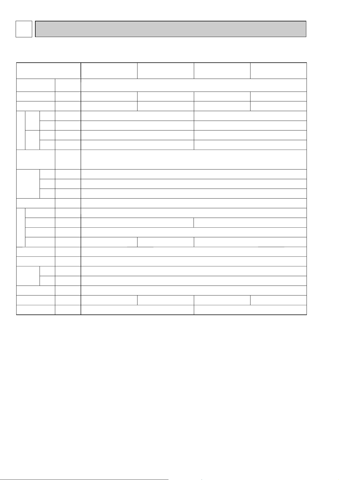
4
Item
kW
kW
kW
kW
A
A
—
mm
mm
mm
—
—
k/min
Pa
kW
—
—
[mm(in.)
[mm(in.)
[mm
dB
kg
Cooling capacity
Power
Heat exchanger
Insulator
Air filter
Fan ✕ No
Air flow W3
Pipe
dimensions
Field drain pipe size
Noise level W3
Product weight
Exterior
(munsell symbol)
Fan motor
output
External
static pressure
Liquid
side
Gas
side
Heating capacity
Dimensions
Height
Width
Depth
Electric characteristic
Input
Cooling
Heating
Cooling
Heating
Current
PLFY-P25VCM-E(1).TH
PLFY-P32VCM-E
(1).TH
PLFY-P20VCM-E
(1).TH
PLFY-P40VCM-E
(1).TH
2.2
2.5
0.011
35-31-28 37-31-29 38-33-29 39-34-30
0.015 0.020
10-9-8
Unit : Galvanized sheets with gray heat insulation Grilles : ABS resin
Munsell<0.70Y 8.59/0.97>(PLFY-P·VCM-E.TH) / <6.4Y 8.9/0.4>(PLFY-P·VCM-E
1.TH)
208 <20>
570<650>
570<650>
Cross fin
Turbo fan ✕ 1
0
Polyethylene sheet
PP honey comb fabric
O.D.32 (PVC pipe VP-25 connectable)
Single phase 220-230-240V 50Hz
V
·
Hz
2.8
3.2
3.6
4.0
4.5
5.0
0.06
0.06
0.28
0.28
0.05
0.05
0.23
0.23
11-10-9
[12.7(1/2")
[6.35(1/4")
17<3>15.5<3>
F a n
SPECIFICATION
SPECIFICATIONS
4-1. SPECIFICATIONS
Note 1. Rating conditions(JIS B 8616)
Cooling : Indoor : D.B. 27°C W.B. 19.0°C
Note 2. The number indicated in < > is for the grille.
W 3. Airflow and the noise level are indicated as High-Medium-Low.
Heating : Indoor : D.B. 20°C
outdoor : D.B. 35°C
outdoor : D.B. 7°C W.B. 6°C
8
Page 9
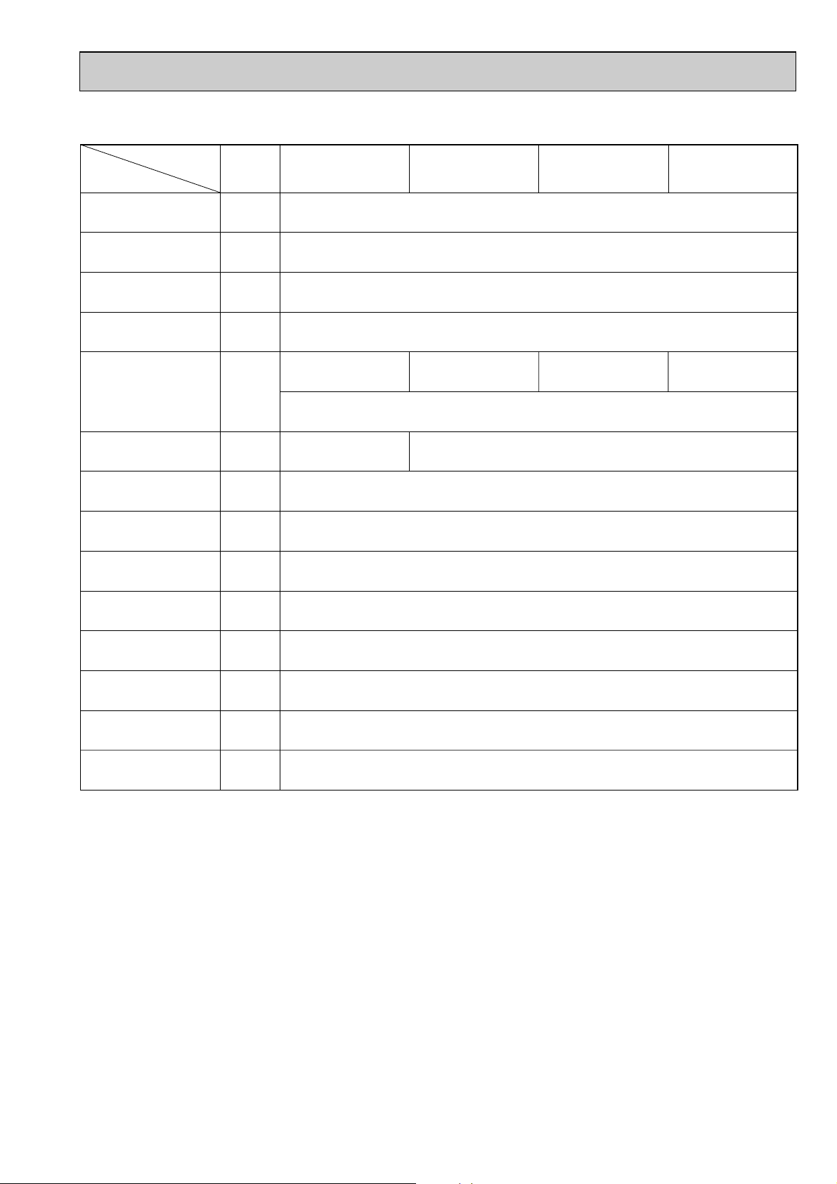
4-2. ELECTRICAL PARTS SPECIFICATIONS
Parts name
Model
Symbol
TH21
TH22
TH23
FUSE
MF
C
MV
DP
DS
LEV
H2
TB2
TB5
TB15
Resistance 0:/15k", 10:/9.6k", 20:/6.3k", 25:/5.4k", 30:/4.3k", 40:/3.0k"
Resistance 0:/15k", 10:/9.6k", 20:/6.3k", 25:/5.4k", 30:/4.3k", 40:/3.0k"
Resistance 0:/15k", 10:/9.6k", 20:/6.3k", 25:/5.4k", 30:/4.3k", 40:/3.0k"
250V 6.3A
240V 15W
(L, N, ;) Rated to 330V 30A w
(M1, M2, S) Rated to 250V 20A w
(1, 2) Rated to 250V 10A w
PLFY-P25VCM-E(1).THPLFY-P20VCM-E(1).TH PLFY-P32VCM-E(1).TH PLFY-P40VCM-E(1).TH
Thermistor
(Room temperature
detection)
Thermistor
(Pipe temperature
detection/ Liquid)
Thermistor
(Pipe temperature
detection/ Gas)
Fuse
(Indoor controller board)
Fan motor
(with Thermal fuse)
Thermal fuse
Electric heater
(Condensation proof)
Power supply terminal
block
Transmission terminal
block
MA remote controller
terminal block
6-pole OUTPUT 15W
PK6V15-LD
6-pole OUTPUT 11W
PK6V11-LF
6-pole OUTPUT 20W
PK6V20-LM
6-pole OUTPUT 20W
PK6V20-LL
MSBPC20M13
DC12V 300
"
/phase
PLD-12230ME-1
INPUT 12/10.8W 24R/Hr
Thermistor resistance 0:/6k", 10:/3.9k", 20:/2.6k", 25:/2.2k", 30:/1.8k", 40:/1.3k"
DC12V Stepping motor drive, Port dimension [ 5.2 (0~2000pulse)
EDM-40YGME
OFF 145: i 2:
1.5+ ✕ 440V1.0+ ✕ 440V
Fan motor capacitor
Vane motor
Drain pump
Drain sensor
Linear expansion valve
[coil]
w Note: Refer to WIRING DIAGRAM for the supplied voltage.
9
Page 10
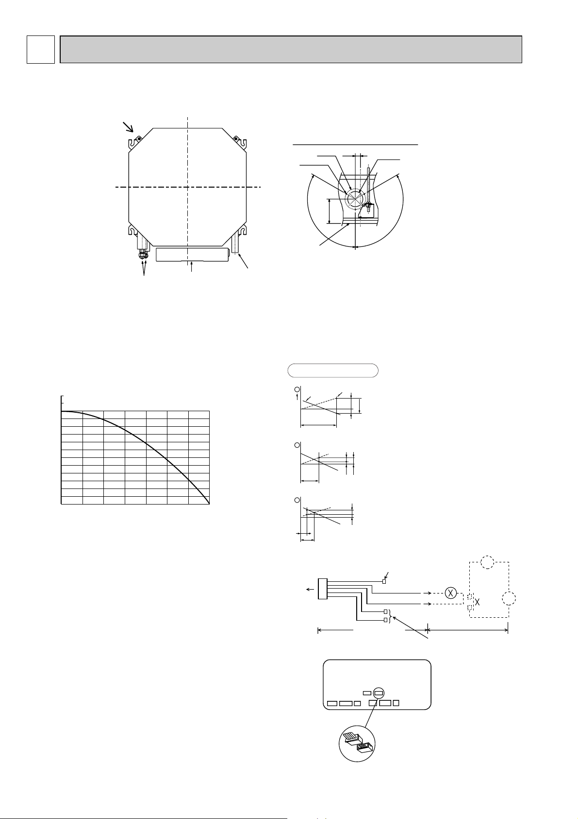
5 4-WAY AIR FLOW SYSTEM
Detail drawing of fresh air intake
Ceiling surface
Refrigerant pipe
Drain pipe
Electrical Box
Cut out hole
[73.4
Burring hole
3-[2.8 hole
[100
118
25
120
°
120
°
Fresh air intake
Static pressure : P [Pa]
Air flow : Q [m
3
/min]
50
-50
-100
-150
-200
-250
-300
0
0.5 1.0 1.5 2.0 2.5 3.0 3.5
Q
0
B
A
C
1
Curve in the
left graphs
Duct characteristics
at site
Q
A
EC
2
Q
Qa
AD
3
CN51
Multiple remote
controller adapter
PAC-SA88HA-E
Indoor controller board
Distance between indoor
controller board and relay
must be within 10m.
Be sure to secure insulation
material by tape, etc.
5
Green
Yellow
Orange
Connector (5P)
Indoor unit side
Multiple remote
controller adapter
PAC-SA88HA-E
Be sure to secure insulation
material by tape, etc.
Installation at site
CN51
on indoor
controller board
Red
Brown
1
~
CN51
MB
5-1. FRESH AIR INTAKE (Location for installation)
At the time of installation, use the duct holes (cut out) located at the positions shown in following diagram, as and when required.
5-2. FRESH AIR INTAKE AMOUNT & STATIC PRESSURE CHARACTERISTICS
PLFY-P20VCM-E(1).TH
PLFY-P25VCM-E(1).TH
PLFY-P32VCM-E(1).TH
PLFY-P40VCM-E(1).TH
Taking air into the unit
NOTE: Fresh air intake amount should be 20% or less of
whole air amount to prevent dew dripping.
5-3. OPERATION IN CONJUNCTION
WITH DUCT FAN (Booster fan)
• Whenever the indoor unit operates, the duct fun also
operates.
(1)Connect the optional multiple remote controller
adapter(PAC-SA88HA-E) to the connector CN51
on the indoor controller board.
(2)Drive the relay after connecting the 12V DC relay
between the Yellow and Orange connector wires.
MB: Electromagnetic switch power relay for duct fan.
X: Auxiliary relay (For DC 12V, coil rating : 1.0W or
below)
How to read curves
10
Q…Designed amount of fresh air intake
<m3/min>
A…Static pressure loss of fresh air
intake duct system with air flow
amount Q <Pa>
B…Forced static pressure at air condi-
tioner inlet with air flow amount Q
<Pa>
C…Static pressure of booster fan with
air flow amount Q <Pa>
D…Static pressure loss increase
amount of fresh air intake duct system for air flow amount Q <Pa>
E…Static pressure of indoor unit with air
flow amount Q <Pa>
Qa…Estimated amount of fresh air
intake without D <m3/min>
Page 11

5-4. FIXING HORIZONTAL VANE
Standard of
horizontal position
Dimension A (mm)
21 25 28 30
Level 30°
(Min.)
Downward 45° Downward 55°
Downward 70°
(Max.)
w Dimension between 21 mm and 30 mm can be arbitrarily set.
Caution
Do not set the dimension out of the range.
Erroneous setting could cause dew drips, smudge on ceiling or malfunction of unit.
<Set range>
.
Horizontal vane of each air outlet can be fixed according to the environment where it is installed.
Setting procedure
1) Turn off a main power supply (Turn off a breaker).
2) Disconnect the vane motor connector of the direction of the arrow with pressing the unlocking button as shown in figure
below.
Insulate the disconnected connector with the plastic tape.
Vane motor
Vane motor
Connector
Horizontal vane
3) Set a vertical vane of the air outlet, which is to be fixed by the hand slowly within the range in the table below.
Measured standard
position of the grille
Horizontal vane
Unlocking button
11
Page 12

6
Brand label
15~37 15~37576~620
530
1
2
Grille
Fresh air intake
Drain pipe
VP-25 connection
Vane motor
Drain hole
V/M
V/M
V/M
V/M
Air intake grille
55 35
35 55
Auto vane
Grille
Air intake hole
Air intake hole
Air outlet hole
Air outlet hole
301
301
Detail drawing of fresh air intake
Ceiling surface
Cut out hole
[73.4
Burring hole
3-[2.8
[100
118
25
120
-
120
-
377
377
650
650
Suspension bolt M10 or W3/8
230
18248
Terminal block
Ceiling surface
235
208
27
+5
0
193
20
93
38~58
66121
17 202
87
31
Ceiling hole
15~37
576~620
420
570
335
199
352
335
Ceiling hole
Grille
Drain pipe
VP-25 connection
(O.D.[32)
Drain hole
55 35
35 55
Auto vane
Grille
Air intake hole
Air outlet hole
301
Detail drawing of fresh air intake
Ceiling surface
Cut out hole
Burring hole
118
25
377
377
650
18248
Terminal block
235
208
27
+5
193
20
93
66121
87
31
15~37
570
335
199
352
335
570
Grille
Drain pipe
Drain hole
55 35
35 55
Auto vane
Grille
Air intake hole
Air outlet hole
301
Detail drawing of fresh air intake
Ceiling surface
Cut out hole
Burring hole
118
25
377
650
Suspension bolt lower edge
18248
Wiring entry
Terminal block
235
208
27
+5
193
20
93
66121
56
57
87
31
Suspension bolt pitch
570
335
199
352
335
Suspension bolt pitch
Models 12
PLFY-P20VCM-E
(1)
PLFY-P25VCM-E(1)
PLFY-P32VCM-E(1)
PLFY-P40VCM-E(1)
Refrigetant pipe
(6.35mm dia.)
flared connection
1/4 inch
Refrigetant pipe
(12.7mm dia.)
flared connection
1/2 inch
OUTLINES AND DIMENSIONS
PLFY-P20VCM-E.TH PLFY-P25VCM-E.TH PLFY-P32VCM-E.TH PLFY -P40VCM-E.TH
PLFY-P20VCM-E1.TH PLFY-P25VCM-E1.TH PLFY-P32VCM-E1.TH PLFY-P40VCM-E1.TH
Unit : mm
12
Page 13

WIRING DIAGRAM7
DP
WHT
(DRAIN)
WHT
FAN
(FAN)
See fig:W1
Notes:
1.At servicing for outdoor unit, always follow the wiring diagram of outdoor unit.
2.In case of using MA-Remote controller, please connect to TB15. (Remote controller wire is non-polar.)
3.In case of using M-NET, please connect to TB5. (Transmisson line is non-polar.)
4.Symbol[S] of TB5 is the shield wire connection.
5.Symbols used in wiring diagram above are, : terminal block, : connecter.
6.The setting of the SW2 dip switches differs in the capacity for the detail, refer to the fig:w1.
MODELS
P20
P25
P32
P40
<fig:W1>
ON
OFF
123456
ON
OFF
123456
ON
OFF
123456
ON
OFF
123456
SW2
Power supply for MA-Remote controller
on ➔ Lamp is lit.
Main power supply(Indoor unit:220-240V)
power on ➔ Lamp is lit.
Main power supply
Power supply for
MA-Remote controller
LED2
LED1
Mark Meaning
LED on indoor controller board for service
Function
CN32
(REMOTE SWITCH)
WHT
321
DC24-30V
CONTROLLER
TO NEXT INDOOR UNIT
PULL BOX
FUSE(15A)
BREAKER
(15A)
50Hz
HA
1234
WHT
CN41
CN51
WHT
(CENTRALLY
CONTROL)
54321
CN52
(REMOTE
INDICATION)
GRN
12345
REMOTE SWITCHCN32
X7 FAN MOTOR (Me)
X6 FAN MOTOR (Hi)
X5 FAN MOTOR (Lo)
SW1 SWITCH MODE SELECTION
CONNECTION No.SW14
SW12
SW11 ADDRESS SETTING 1ST DIGIT
ADDRESS SETTING 2ND DIGIT
MODEL SELECTION
MODE SELECTION
CAPACITY CODE
SW4
SW3
SW2
(0:/15T 25:/5.4T)
(0:/15T 25:/5.4T)
DP
DRAIN PUMP
DS
DRAIN SENSOR
H2
DEW PREVENTION HEATER
FAN MOTOR (LL)
DRAIN PUMP/DEW PREVENTION HEATERX1 AUX. RELAY
SYMBOL NAME
VARISTOR
INDOOR POWER BOARD
P.B
ZNR
X4
I.B
CN41
CN51
CN52
FUSE FUSE (6.3A/250V)
REMOTE INDICATION
CENTRALLY CONTROL
HA TERMINAL-A
CONNECTOR
INDOOR CONTROLLER BOARD
[LEGEND]
NAMESYMBOL
PIPE TEMPERATURE DETECTION/GAS
TH23
TRANSMISSION
TERMINAL
BLOCK
POWER SUPPLY
TB5
TB15
TB2
(0:/15T 25:/5.4T)
THERMISTOR ROOM TEMPERATURE DETECTION
TH22
TH21
LEV
LINEAR EXPANSION VALVE
MV
MF
VANE MOTOR
FAN MOTOR (WITH THERMAL FUSE)
CAPACITOR (FAN MOTOR)
C1
PIPE TEMPERATURE DETECTION/LIQUID
MA-REMOTE CONTROLLER
LED2
LED1
31 13
CND
(POWER)
YLW
31
YLW
13
BLU
(D·U·M)
CNC
(D·HEATER)
RED
ORN
FUSE
ZNR
CNP
X1
RED
ORN
GRILLE
BLU
5
WHT
BLU
RED
ORN
YLW
YLW
1
10
7
2
3
6
4
5
8
9
3
5
5
5
5
C1
15
BLK
YLW
WHT
BRN
79
X6 X5 X4 X7
X4X7X5X6
MF
I.B
CN20
CN31
123
BLU
WHT
ORN
RED
YLW
6
6 54321
(VANE)
CN6V
GRN
RED
ORN
BLU
654321
(LEV)
CN60
WHT
WHT
YLW
BRN
BLK
2211
(LIQUID)
(INTAKE)
CN21
RED WHT
21
(GAS)
CN29
(REMOCON)
WHT
13
RED
P.B
RED
CNDK
(POWER
BORD)
1
2
3
AC220-240V
CNSK(RED)
TB2
L
N
RED
BLU
GRN/YLW
~/N 220-240V
POWER SUPPLY
TRANS
DC13.1V
CN2S(WHT)
2
1
21
(POWER
BORD)
CN2D
WHT
WHT
BLK
M1
1
2
CONTROLLER
DC8.7-13V
TO MA-REMOTE
CN2M
(M-NET)
1231
CN3A
BLU
BLU
M2
TB15
S(SHIELD)
M-NET REMOTE
TO OUTDOOR UNIT
BC CONTROLLER
TB5
X1
TH23
TH22
TH21DS
LEV
5
3RD
DIGIT
0
O
0
0N
0FF
SW1
12345678910
SW12
SW11
1ST
DIGIT
0
2ND
DIGIT
SW14
CONNECTION
No.
12345
0FF
0N
SW4
SW2
65432110987654321
0FF
0N
SW3
MV
H2
MV
MV
MV
PLFY-P20VCM-E.TH PLFY-P25VCM-E.TH PLFY-P32VCM-E.TH PLFY-P40VCM-E.TH
PLFY-P20VCM-E1.TH PLFY-P25VCM-E1.TH PLFY-P32VCM-E1.TH PLFY-P40VCM-E1.TH
13
Page 14

8 REFRIGERANT SYSTEM DIAGRAM
Strainer (#50mesh)
Strainer (#100mesh)
Unit : mm(inch)
Strainer1 (#50mesh)
Strainer2 (#100mesh)
Heat exchanger
Thermistor (Room temparature detection) TH21
Thermistor (Pipe temperature detection/ Gas) TH23
Thermistor (Pipe
temperature
detection/ Liquid) TH22
Linear expansion valve
Gas pipe
Liquid pipe
Flare connection
Gas pipe
Liquid pipe
[12.7(1/2)
[6.35(1/4)
PLFY-P20VCM-E.TH PLFY-P25VCM-E.TH PLFY-P32VCM-E.TH PLFY-P40VCM-E.TH
PLFY-P20VCM-E1.TH PLFY-P25VCM-E1.TH PLFY-P32VCM-E1.TH PLFY-P40VCM-E1.TH
14
Page 15

DISASSEMBLY PROCEDURE9
PLFY-P20·P25·P32·P40VCM-E.TH
PLFY-P20·P25·P32·P40VCM-E1.TH
OPERATING PROCEDURE PHOTOS&ILLUSTRATIONS
1. Removing the air intake grille
(1) Slide the knob of air intake grille to the direction of the
arrow 1 to open the air intake grille.
(2) Remove the string hook from the panel to prevent the grille
from dropping.
(3) Slide the hinge of the intake grille to the direction of the
arrow 2 and remove the air intake grille.
2. Removing the fan guard
(1) Open the air intake grille.
(2) Remove the 3 screws of fan guard.
Be careful on removing heavy parts.
Figure 1
Air intake grille
Grille
Air intake grille knob
Photo 1
Fan guard
Screws
3. Removing the panel
(1) Remove the air intake grille. (Refer to 1)
Corner panel (See figure 2)
(1) Remove the screw of the corner.
(2) Slide the corner panel to the direction of the arrow 3, and
remove the corner panel.
Panel (See photo 2)
(1) Disconnect the connector that connects with the unit.
(2) Remove the 2 screws from the panel and loose other 2
screws fixed to the oval hole, have different diameter.
(3) Rotate the panel a little to remove the screws.(Slide the
panel so that the screw comes to a larger diameter of the
oval hole, which has 2 different diameters.)
4. Removing the electrical parts
(1) Remove the 2 screws and the control box cover.
<Electrical parts in the control box>
• Indoor controller board (I.B)
• Indoor power board (P.B)
• Fan motor capacitor (C1)
• Fuse (FUSE)
• Varistor (ZNR)
• Terminal block (TB)
Figure 2
Corner
panel
Photo 2
Connector
Screws
Photo 3
Fan motor
Capacitor
(C1)
Screw
Indoor
controller
board (I.B)
Corner
panel
Indoor
power
board
(P.B)
Air intake grille
Panel
Terminal
block
(TB5)
Screws
Panel
Terminal
block
(TB15)
15
Indoor controller
box
Varistor
(ZNR)
Fuse
(FUSE)
Terminal
block
(TB2)
Page 16

OPERATING PROCEDURE
PHOTOS&ILLUSTRATIONS
5. Removing the room temperature detection (TH21)
(1) Remove the panel. (Refer to 3)
(2) Pull out the room temperature detection from the drain
pan.
(3) Remove the 2 screws fixed to the control box cover, and
remove the control box cover.
(4) Remove the connector (CN20) from the indoor controller
board, and disconnect the room temperature detection.
6. Removing the drain pan
(1) Remove the panel. (Refer to 3)
(2) Remove the room temperature detection and the 2 lead
wires held with fastener; wireless controller board relay
connector (9P red) and panel relay connector (10P white).
(3) Remove the 4 screws fixed to the drain pan, and remove
the drain pan.
(4) Remove the fan guard. (Refer to 2)
7. Removing the pipe temperature detection/liquid (TH22)
and pipe temperature detection/gas (TH23)
(1) Remove the panel. (Refer to 3)
(2) Remove the drain pan. (Refer to 6)
(3) Disconnect the pipe temperature detection/liquid or the pipe
temperature detection/gas from the holder.
(4) Remove the 3 screws fixed to the piping cover, and
remove the piping cover. (See photo 9)
(5) Remove the 2 screws fixed to the control box cover, and
remove the control box cover.
Photo 4
Screw
Room
temperature
detection
(TH21)
Screw
Photo 5
Control box
Fan guard
Control box
Connectors
Drain plug
Screw
Drain pan
Screw
LEV
Pipe temperature detection/liquid (TH22)
(6) Remove the connector (CN21) from the indoor controller
board, and disconnect the pipe temperature detection/liquid.
Pipe temperature detection/gas (TH23)
(6) Remove the connector (CN29) from the indoor controller
board, and disconnect the pipe temperature detection/gas
with its holder.
8. Removing the fan motor (MF)
(1) Remove the panel. (Refer to 3)
(2) Remove the drain pan. (Refer to 6)
(3) Remove the nut and the washer from the turbo fan, and
remove the turbo fan.
(4) Remove the 2 screws fixed to the control box cover, and
remove the control box cover.
(5) Disconnect the connector of the FAN from the indoor con-
troller board.
(6) Remove the 3 screws fixed to the piping cover, and
remove the piping cover. (See photo 9)
(7) Remove the 6 screws fixed to the flat plate, and remove
the flat plate.
(8) Disconnect the lead wires to the direction of the fan motor,
and remove the 3 nuts of the fan motor.
Photo 6
Nut
Flat plate
Fan
motor
(MF)
Thermistor
(Pipe temperature
detection/ Liquid)
(TH22)
Screws
Nuts
Thermistor
(Pipe temperature
detection/ Gas)
(TH23)
Screws
Lead
wires
Screws
16
Page 17

OPERATING PROCEDURE PHOTOS&ILLUSTRATIONS
9. Removing the drain pump (DP) and drain sensor (DS)
(1) Remove the panel. (Refer to 3 )
(2) Remove the drain pan. (Refer to 6)
(3) Remove the 2 screws fixed to the control box cover, and
remove the control box cover.
(4) Remove the connectors of the (CNP) and the (CN31)
from the indoor controller board.
(5) Remove the 1 screw fixed to the cover, and remove the
cover.
(6) Disconnect the lead wires to the direction of the drain
pump.(See photo 7)
(7) Remove the 3 screws of the drain pump.
(8) Cut the drain hose band, pull out the drain hose from the
drain pump.
(9) Pull out the drain pump.
(10) Remove the drain sensor and the holder.
10. Removing the heat exchanger
(1) Remove the panel. (Refer to 3 )
(2) Remove the drain pan. (Refer to 6)
(3) Remove the nut and the washer from the turbo fan, and
remove the turbo fan.
(4) Remove the 2 screws fixed to the control box cover, and
remove the control box cover.
(5) Disconnect the connector of the FAN from the indoor con-
troller board.
(6) Remove the 3 screws fixed to the piping cover, and
remove the piping cover. (See photo 9)
(7) Remove the pipe temperature thermistor/liquid and
condenser/evaporator temperature thermistor. (Refer to 7)
(8) Disconnect the lead wires to the direction of the fan motor.
(9) Remove the 1 coil support screw, the 2 inside coil screws
(See photo 10), and the 4 outside coil screws (See photo 9)
from the heat exchanger, and remove the heat exchanger.
Photo 7
Control
box
Photo 8
Drain
hose
Screw
Photo 9
Piping cover
Drain sensor (DS) Drain pump (DP)
Fixing band
Screws of
piping cover
Screw
Lead wires
Cover
Control box
Lead wires
Screws
Control box
Coil
screws
17
Photo 10
Coil
support
Coil
support Screw
Coil screws
Heat exchanger
Page 18

10
Parts name Check points
Disconnect the connector then measure the resistance with a tester.
(At the ambient temperature 10:~30:)
Disconnect the connector then measure the valve resistance with a tester.
Measure the resistance between the terminals with a tester.
(At the ambient temperature 20:~30:)
Measure the resistance between the terminals with a tester.
(At the ambient temperature 20:~30:)
Measure the resistance after 3 minutes have passed since the power supply was intercepted.
(At the ambient temperature 0:~60:)
Vane motor (MV)
Linear expansion
valve (LEV)
Drain pump (DP)
Drain sensor (DS)
Refer to the next page for the details.
Refer to the next page for the details.
Thermistor (TH21)
(Room temperature
detection)
Thermistor (TH22)
(Pipe temperature
detection/ Liqid)
Thermistor (TH23)
(Pipe temperature
detection/ Gas)
1
2
Yellow
Relay
connector
Yellow
1
2
3
Normal
4.3k"~9.6k"
Abnormal
Open or short
Abnormal
Open or short
Normal
0.6k"~6.0k"
Abnormal
Open or short
Normal
150k" i10%
White-Red Yellow-Brown Orange-Red Blue-Brown
NormalConnector Abnormal
300" Open or short
Normal Abnormal
290" Open or short
Orange
Red
White
Blue
Brown
Yellow
M
Orange
Red
White
Red — Yellow
Red — Blue
Red — Orange
Red — White
Blue
Yellow
Fan motor (MF)
M
Refer to the next
page for the details.
BLK RED ORNYLW
BLU
BRN
WHT
P
Measure the resistance between the terminals with a tester.
(Coil wiring temperature 10°C ~ 30°C)
Normal
WHT-BLK
BLK-BLU
BLU-YLW
YLW-RED
RED-BRN
390"~423"
82"~90"
28"~32"
158"~172"
378"~409"
157"~170"
44"~49"
306"~332"
312"~338"
137"~149"
44"~49"
296"~321"
302"~327"
91"~100"
38"~42"
265"~288"
Abnormal
Opened or
short-circuited
P : Thermal fuse 145˚C ± 2˚C
PLFY-P20VCM-E(1) PLFY-P25VCM-E(1) PLFY-P32VCM-E(1) PLFY-P40VCM-E(1)
TROUBLESHOOTING
10-1. HOW TO CHECK THE PARTS
PLFY-P20VCM-E.TH PLFY-P25VCM-E.TH PLFY-P32VCM-E.TH PLFY-P40VCM-E.TH
PLFY-P20VCM-E1.TH PLFY-P25VCM-E1.TH PLFY-P32VCM-E1.TH PLFY-P40VCM-E1.TH
18
Page 19

-200 20406080
< Thermistor for drain sensor >
Temperature (:)
0
1
2
3
4
5
6
7
8
9
10
Resistance (k")
<Thermistor characteristic graph>
Thermistor for
lower temperature
Thermistor (TH21)
(Room temperature detection)
Thermistor (TH22)
(Pipe temperature detection/ Liquid)
Thermistor (TH23)
(Pipe temperature detection/ Gas)
Thermistor R0=15k' ±3%
Fixed number of B=3480K ± 2%
Rt=15exp { 3480( ) }
1
273+t
1
273
0: 15k'
10: 9.6k'
20: 6.3k'
25: 5.4k'
30: 4.3k'
40: 3.0k'
Thermistor for
drain sensor
Thermistor R0=6.0k' ±5%
Fixed number of B=3390K ±2%
< Thermistor for lower temperature >
50
40
30
20
Resistance (k")
10
0
-20 -10 0 10 20 30 40 50
Temperature (:)
Rt=6exp { 3390( ) }
0: 6.0k'
10: 3.9k'
20: 2.6k'
25: 2.2k'
30: 1.8k'
40: 1.3k'
60: 0.6k'
Linear expansion valve
① Operation summary of the linear expansion valve
• Linear expansion valves open/close through the use of a stepping motor after receiving the pulse signal from the indoor
controller board.
• Valve position can be changed in proportion to the number of pulse signals.
<Connection between the indoor controller board and the linear expansion valve>
Note : Since the number of the connector at the controller board side and the relay connector are different, follow the color of
the lead wire.
1
273+t
Linear expansion valve
4
[4
M
6
[2
5
[3
Orange
2
3
White
[1
1
Red
Blue
Brown
Yellow
1
273
Controller board
DC12V
Brown
Red
[4
[3
[2
[1
Blue
Orange
Yellow
White
Connector(CN60)
6
5
4
3
2
1
Drive circuit
[4
[3
[2
[1
19
Page 20

<Output pulse signal and the valve operation>
D
A
E
B
C
Open
Extra tightening (200~800pulse)
Pulse number
Close
Open
Outdoor unit R410A model : 1400 pulse
Outdoor unit R22/R407C model : 2000 pulse
Opening a valve
all the way
Close
Valve position (capacity)
Thermistor
(Liquid pipe)
Linear
expansion
valve
Output
(Phase)
{1
{2
{3
{4
Linear expansion valve operation
➁
1
ON
ON
OFF
OFF
2
OFF
ON
ON
OFF
Output
3
OFF
OFF
ON
ON
4
ON
OFF
OFF
ON
Closing a valve : 1 → 2 → 3 → 4 → 1
Opening a valve : 4 → 3 → 2 → 1 → 4
The output pulse shifts in above order.
• When linear expansion valve operation stops, all output phase
become OFF.
• At phase interruption or when phase does not shift in order, motor
does not rotate smoothly and motor will lock and vibrate.
• When the switch is turned on, 2200 pulse closing valve signal will be
send till it goes to point
A in order to define the valve position.
• When the valve moves smoothly, there is no sound or vibration
occurring from the linear expansion valves : however, when the
pulse number moves from E to A or when the valve is locked, more
sound can be heard than in a normal situation.
• Sound can be detected by placing the ear against the screw driver
handle while putting the screw driver tip to the linear expansion
valve.
Troubleshooting
➂
Symptom
Operation circuit failure of the micro
processor
Linear expansion
valve mechanism is
locked.
Short or breakage of
the motor coil of the
linear expansion
valve
Valve doesn't close
completely.
Wrong connection of
the connector or
contact failure
Check points
Disconnect the connector on the controller board, then connect LED for checking.
When power is turned on, pulse signals will output for 10 seconds. There must be some defects in the operation circuit if
the LED does not light while the signals are output or keeps
lighting even after the signals stop.
Motor will idle and make a ticking noise when the motor is
operated while the linear expansion valve is locked. This
ticking sound is the sign of the abnormality.
Measure the resistance between each coil (white-red, yellowbrown, orange-red, blue-brown) with a tester. It is normal if
the resistance is in the range of 150Ω ±10%.
To check the linear expansion valve, operate the indoor unit
in fan mode and at the same time operate other indoor units
in cooling mode, then check the pipe temperature <liquid
it means the valve is not closed all the way. It is not necessary to exchange the linear expansion valve, if the leakage is
small and not affecting normal operation.
Check the color of lead wire and missing terminal of the connector.
pipe temperature> of the indoor unit by the
outdoor multi controller board operation
monitor. During fan operation, linear
expansion valve is closed completely and if
there is any leaking, detecting temperature
of the thermistor will go lower. If the detected temperature is much lower than the temperature indicated in the remote controller,
LED1k"
6
5
4
3
2
1
20
Countermeasures
Exchange the indoor controller board at drive circuit
failure.
Exchange the linear
expansion valve.
Exchange the linear
expansion valve.
If large amount of refrigerant is leaked, exchange
the linear expansion valve.
Disconnect the connector
at the controller board,
then check the continuity.
Page 21

10-2. FUNCTION OF DIP SWITCH
Switch Function Remarks
Pole
ON OFF
Thermistor <Room temperature
Operation by switch
SW1
Function
Selection
1
detection> position
2
Filter clogging detection
3
Filter cleaning
4
Fresh air intake
5
Remote indication switching
6
Humidifier control
7
Air flow set in case of
Heat thermo OFF
8
9
Auto restart function
10
Power ON/OFF
Built-in remote controller
Provided
2,500h
Effective
Thermo ON signal indication
Fan operation at Heating mode
Low w3
Setting air flow w3
Effective
Effective
Indoor unit
Not provided
100h
Not effective
Fan output indication
Thermo ON operation at heating mode
Extra low w3
Depends on SW1-7
Not effective
Not effective
Effective
timing
Under
suspension
Indoor controller board
<Initial setting>
ON
OFF
123456789
w
SW 1-8
SW 1-7
OFF
OFF
ON
ON
Extra low
Low
Setting air flow
stop
OFF
ON
OFF
ON
Indoor controller board
SW2
Capacity
code
setting
Capacity
P20 P32
1~6
P25 P40
SW 2 Capacity SW 2
ON
OFF
123456
ON
OFF
123456
ON
OFF
123456
ON
OFF
123456
Before
power
supply
ON
<Initial setting>
Set for each capacity.
10
SW3
Function
setting
SW4
Unit
Selection
Heat pump / Cooling only
1
Louver
2
Vane
3
Vane swing function
4
Vane horizontal angle
5
Vane cooling limit angle setting w4
6
Indoor linear expansion
7
valve opening
Heat 4degrees up
8
Superheat setting temperature
9
Sub cool setting temperature
10
Cooling only
Available
Available
Available
Second setting
Horizontal angle
Effective
Not effective
w5
w5
Heat pump
Not available
Not available
Not available
w6
First setting
Down B, C
Not effective
Effective
—
—
In case of replacing the indoor controller board, make sure to set the switch to
the initial setting, which is shown below.
1~5
ON
OFF
12345
Indoor controller board
Set while the unit is off.
<Initial setting>
ON
OFF
123456789
Under
suspension
—
Note :
w4
At cooling mode, each angle
can be used only 1 hour.
w5
Do not use SW3-9, 10 as
trouble might be caused by
the usage condition.
w6 Second setting is same as
first setting.
10
—
Indoor controller board
Before
power
supply
ON
21
Page 22

0
5
9
4
8
3
7
2
6
1
0
5
9
4
8
3
7
2
6
1
0
5
9
4
8
3
7
2
6
1
0
5
9
4
8
3
7
2
6
1
0
8
F
7
E
6
D
5
C
4
B
3
A
2
9
1
0
8
F
7
E
6
D
5
C
4
B
3
A
2
9
1
Rotary switchRotary switch
SW14
Connection
No.
setting
SW11
1st digit
address
setting
SW12
2nd digit
address
setting
Pole Operation by switch
Address setting should be done when M-NET
remote controller is being used.
This is the switch to be used when the indoor
unit is operated with R2 series outdoor unit
as a set.
Remarks
<Initial setting>
SW1210SW11
1
SW12 SW11
SW14
SW14
<Initial setting>
Effective
timing
Before
power
supply
ON
Indoor controller board
Indoor controller board
22
Page 23

10-3. TEST POINT DIAGRAM
10-3-1. Indoor controller board
PLFY-P20VCM-E.TH PLFY-P25VCM-E.TH PLFY-P32VCM-E.TH PLFY-P40VCM-E.TH
PLFY-P20VCM-E1.TH PLFY-P25VCM-E1.TH PLFY-P32VCM-E1.TH PLFY-P40VCM-E1.TH
CN2M
Connect to the terminal block (TB5)
(M-NET transmission connecting wire)
24-30V DC (non-polar)
CN2D
Connect to the indoor
power board (CN2S)
12.5-13.7V DC (Pin11(+))
LED1
Main power supply
(Indoor unit : 220-240V)
CNDK
Connect to the indoor power
board (CNSK)
Between
CNP
Drain pump output (DP)
Between
11
to 33220-240V AC
11
to 33220-240V AC
FUSE
6.3A 250V
CN3A
Connect to the terminal block (TB15)
(MA-Remote controller connecting wire)
11
Between
to 338.7-13V DC (Pin11(+))
LED2
Power supply for
MA-Remote controller
CN29
Pipe temperature
detection/Gas (TH23)
CN21
Pipe temperature
detection/Liquid (TH22)
CN20
Room temperature
detection (TH21)
CN31
Drain sensor (DS)
CN60
Linear expansion valve
output (LEV)
CN6V
Vane motor output (MV)
CND
Power supply for
indoor controller board
Between
FAN
Fan motor output (MF)
11
to 33220-240V AC
CN27
Connector
(Damper)
CN32
Connector
(Remote switch)
CN52
Remote indication
CN51
Centrally control
SW4
Model selection
SW3
Function setting
SW2
Capacity setting
CN25
Connecter(Humidifier)
23
Page 24

10-3-2. Indoor power board
PLFY-P20VCM-E.TH PLFY-P25VCM-E.TH PLFY-P32VCM-E.TH PLFY-P40VCM-E.TH
PLFY-P20VCM-E1.TH PLFY-P25VCM-E1.TH PLFY-P32VCM-E1.TH PLFY-P40VCM-E1.TH
CN2S
Connect to the indoor controller board (CN2D)
11
Between
33
to
12.6-13.7V DC (Pin11(+))
CNSK
Connect to the indoor controller board (CNDK)
11
Between
to 33220-240V AC
24
Page 25

PARTS LIST (Non-RoHS compliant)11
No. Parts No.
Specification
Remarks
(Drawing No.)
Wiring
Diagram
Symbol
Recom-
mended
Q'ty
1
2
3
4
5
6
7
8
9
10
1
4
4
1
1
4
8
4
4
1
MV
Including H2
E07 158 003
E07 103 037
E07 103 975
E07 103 100
E07 103 010
E07 103 303
E07 103 044
E07 103 031
E07 103 032
–
AIR OUTLET GRILLE
AUTO VANE
CORNER PANEL
AIR FILTER
INTAKE GRILLE
VANE MOTOR
VANE BUSH
GEAR (V)
GEAR (M)
REMOTE CONTROLLER PAR-21MAA
Parts name
SLP-2AA
Q'ty/set
ON/OFF
TEMP.
PANEL PARTS
SLP-2AA(FOR PLFY-P20·P25·P32·P40VCM-E.TH)
9
GEAR(M)
8
GEAR(V)
2
1
VANE BUSH
6
VANE MOT OR
3
4
10
5
7
25
Page 26

FUNCTIONAL PARTS
PLFY-P20VCM-E.TH
PLFY-P25VCM-E.TH
PLFY-P32VCM-E.TH
PLFY-P40VCM-E.TH
3
4
5
6
24
25
1
3
2
24
23
22
DRAIN SENSOR
21
20
SPL WASHER
7
8
9
10
11
12
19
SENSOR HOLDER
/ TH23
PIPE TEMPERA-
18
TURE DETECTION
/ GAS
PIPE TEMPERA-
17
TURE DETECTION
/ LIQUID
16
ROOM TEMPERATURE DETECTION
13
15
14
26
Page 27

No. Parts No.
1
E07 104 290
2
E07 104 124
3
E07 104 808
4
E07 105 124
E07 154 620
5
E07 155 620
6
E07 154 640
7
E07 104 105
E07 168 300
E07 162 300
8
E07 164 300
E07 166 300
9
E07 104 816
10
E07 104 502
11
E07 104 097
12
E07 104 700
13
E07 154 308
14
E07 104 520
15
E07 104 524
16
E07 104 648
17
E07 154 307
18
E07 154 309
19
E07 154 241
20
E07 104 702
21
E07 104 266
22
E07 104 241
23
E07 104 355
24
E07 104 809
25
E07 154 006
Parts name
Specification
BASE
DRUM-1
LEG-1
DRUM-2
INDOOR HEAT EXCHANGER
INDOOR HEAT EXCHANGER
LINEAR EXPANSION VALVE
MOTOR MOUNT
INDOOR FAN MOTOR
INDOOR FAN MOTOR
INDOOR FAN MOTOR
INDOOR FAN MOTOR
PK6V11-LF
PK6V15-LD
PK6V20-LL
PK6V20-LM
FLAT PLATE
TURBO FAN
SPL WASHER
DRAIN PAN
RO0M TEMPERATURE DETECTION
FAN GUARD
DRAIN PLUG
COIL SUPPORT
PIPE TEMPERATURE DETECTION/LIQUID
PIPE TEMPERATURE DETECTION/GAS
SENSOR HOLDER/TH23
(TH23)
DRAIN HOSE
DRAIN SENSOR
SENSOR HOLDER
(DS)
DRAIN PUMP
LEG-2
COVER (DRUM)
1
1
2
1
1
1
3
1
1
1
1
1
1
1
1
1
1
1
1
1
1
1
1
2
1
Q'ty/set
PLFY-
P25P20 P40P32
VCM-E.TH
1
1
1
1
2
2
1
1
1
1
1
1
3
3
1
1
1
1
1
1
1
1
1
1
1
1
1
1
1
1
1
1
1
1
1
1
1
1
1
1
1
1
1
1
1
1
2
2
1
1
Remarks
(Drawing No.)
1
1
2
1
1
1
3PCS/SET
3
1
1
1
1
1
1
1
1
1
1
1
1
1
1
1
1
2
1
Wiring
Diagram
Symbol
LEV
MF
MF
MF
MF
TH21
TH22
TH23
DS
DP
Recommended
Q'ty
27
Page 28

a
a
b
a
b
a
(TB5)
(TB2)
TRANSMISSION
POWER
ELECTRICAL PARTS
No. Parts No.
Parts name
Specification
Remarks
(Drawing No.)
Wiring
Diagram
Symbol
Recommended
Q'ty
1
2
3
4
5
6
7
8
E07 154 350
E02 095 350
E07 154 447
E07 155 447
E07 156 447
E07 157 447
E02 661 385
E07 006 382
E07 155 375
E07 154 375
E07 156 375
E07 154 440
CAPACITOR
CAPACITOR
INDOOR CONTROLLER BOARD
INDOOR CONTROLLER BOARD
INDOOR CONTROLLER BOARD
INDOOR CONTROLLER BOARD
VARISTOR
FUSE
TERMINAL BLOCK
TERMINAL BLOCK
TERMINAL BLOCK
INDOOR POWER BOARD
C1
C1
I.B
I.B
I.B
I.B
ZNR
FUSE
TB2
TB5
TB15
P.B
1.0+ / 40VAC
1.5+ / 440VAC
250V 6.3A
3P(L, N, ;)
3P(M1, M2, S)
2P(1, 2)
PLFY-
Q'ty/set
P20 P25 P32 P40
VCM-E.TH
1
1
1
1
1
1
1
1
1
1
1
1
1
1
1
1
1
1
1
1
1
1
1
1
1
1
1
1
1
1
1
1
PLFY-P20VCM-E.TH
PLFY-P25VCM-E.TH
PLFY-P32VCM-E.TH
PLFY-P40VCM-E.TH
8
1
7
6
5
2
3
4
28
Page 29

No. Parts No.
Specification
Remarks
(Drawing No.)
Wiring
Diagram
Symbol
Recom-
mended
Q'ty
1
2
3
4
5
6
7
8
9
10
1
4
4
1
1
4
8
4
4
1
MV
E17 158 003
E17 424 003
E17 103 037
E17 423 037
E17 103 975
E17 423 975
E17 103 100
E17 103 010
E17 423 010
E17 103 303
E17 103 044
E17 103 031
E17 103 032
–
AIR OUTLET GRILLE
AIR OUTLET GRILLE
AUTO VANE
AUTO VANE
CORNER PANEL
CORNER PANEL
AIR FILTER
INTAKE GRILLE
INTAKE GRILLE
VANE MOTOR
VANE BUSH
GEAR (V)
GEAR (M)
REMOTE CONTROLLER
Parts name
2AAW
1
4
4
1
1
4
8
4
4
1
2AA
SLP-
Q'ty/set
Including H2
Including H2
PAR-21MAA
RoHS
G
G
G
G
G
G
G
G
G
G
G
G
G
G
ON/OFF
TEMP.
RoHS PARTS LIST (RoHS compliant)12
PANEL PARTS
SLP-2AA(FOR PLFY-P20·P25·P32·P40VCM-E.TH)
SLP-2AAW(FOR PLFY-P20·P25·P32·P40VCM-E1.TH)
9
GEAR(M)
8
GEAR(V)
2
1
VANE BUSH
6
VANE MOT OR
3
4
10
5
7
29
Page 30

FUNCTIONAL PARTS
PLFY-P20VCM-E.TH
PLFY-P25VCM-E.TH
PLFY-P32VCM-E.TH
PLFY-P40VCM-E.TH
PLFY-P20VCM-E1.TH
PLFY-P25VCM-E1.TH
PLFY-P32VCM-E1.TH
PLFY-P40VCM-E1.TH
24
25
1
2
3
3
24
23
4
22
5
DRAIN SENSOR
21
6
20
19
SENSOR HOLDER
/ TH23
7
8
PIPE TEMPERA-
18
TURE DETECTION
/ GAS
PIPE TEMPERA-
17
TURE DETECTION
/ LIQUID
9
16
SPL WASHER
ROOM TEMPERATURE DETECTION
10
11
12
13
15
14
30
Page 31

RoHS
G
G
G
G
G
G
G
G
G
G
G
G
G
G
G
G
G
G
G
G
G
G
G
G
G
G
G
G
G
No. Parts No.
Parts name
Specification
Remarks
(Drawing No.)
Wiring
Diagram
Symbol
Recom-
mended
Q'ty
1
2
3
4
5
6
7
8
9
10
11
12
13
14
15
16
17
18
19
20
21
22
23
24
25
3PCS/SET
E17 104 290
E17 104 124
E17 104 808
E17 105 124
E17 154 620
E17 155 620
E17 154 640
E17 104 105
E17 168 300
E17 162 300
E17 164 300
E17 166 300
E17 104 816
E17 104 502
E17 104 097
E17 104 700
E17 154 308
E17 104 520
E17 104 524
E17 104 648
E17 154 307
E17 154 309
E17 154 241
E17 104 702
E17 104 266
E17 104 241
E17 104 355
E17 104 809
E17 154 006
BASE
DRUM-1
LEG-1
DRUM-2
INDOOR HEAT EXCHANGER
INDOOR HEAT EXCHANGER
LINEAR EXPANSION VALVE
MOTOR MOUNT
INDOOR FAN MOTOR
INDOOR FAN MOTOR
INDOOR FAN MOTOR
INDOOR FAN MOTOR
FLAT PLATE
TURBO FAN
SPL WASHER
DRAIN PAN
RO0M TEMPERATURE DETECTION
FAN GUARD
DRAIN PLUG
COIL SUPPORT
PIPE TEMPERATURE DETECTION/LIQUID
PIPE TEMPERATURE DETECTION/GAS
SENSOR HOLDER/TH23
DRAIN HOSE
DRAIN SENSOR
SENSOR HOLDER
DRAIN PUMP
LEG-2
COVER (DRUM)
1
1
2
1
1
1
3
1
1
1
1
1
1
1
1
1
1
1
1
1
1
1
1
2
1
LEV
MF
MF
MF
MF
TH21
TH22
TH23
DS
DP
PK6V11-LF
PK6V15-LD
PK6V20-LL
PK6V20-LM
(TH23)
(DS)
1
1
2
1
1
1
3
1
1
1
1
1
1
1
1
1
1
1
1
1
1
1
1
2
1
1
1
2
1
1
1
3
1
1
1
1
1
1
1
1
1
1
1
1
1
1
1
1
2
1
1
1
2
1
1
1
3
1
1
1
1
1
1
1
1
1
1
1
1
1
1
1
1
2
1
PLFY-
Q'ty/set
P25P20 P40P32
VCM-E
(1).TH
31
Page 32

ELECTRICAL PARTS
RoHS
G
G
G
G
G
G
G
G
G
G
G
G
No. Parts No.
Parts name
Specification
Remarks
(Drawing No.)
Wiring
Diagram
Symbol
Recom-
mended
Q'ty
1
2
3
4
5
6
7
8
E17 154 350
E12 095 350
E17 154 447
E17 155 447
E17 156 447
E17 157 447
E12 661 385
E17 006 382
E17 155 375
E17 154 375
E17 156 375
E17 154 440
CAPACITOR
CAPACITOR
INDOOR CONTROLLER BOARD
INDOOR CONTROLLER BOARD
INDOOR CONTROLLER BOARD
INDOOR CONTROLLER BOARD
VARISTOR
FUSE
TERMINAL BLOCK
TERMINAL BLOCK
TERMINAL BLOCK
INDOOR POWER BOARD
C1
C1
I.B
I.B
I.B
I.B
ZNR
FUSE
TB2
TB5
TB15
P.B
1.0+ / 40VAC
1.5+ / 440VAC
250V 6.3A
3P(L, N, ;)
3P(M1, M2, S)
2P(1, 2)
PLFY-
Q'ty/set
P20 P25 P32 P40
VCM-E
(1).TH
1
1
1
1
1
1
1
1
1
1
1
1
1
1
1
1
1
1
1
1
1
1
1
1
1
1
1
1
1
1
1
1
PLFY-P20VCM-E.TH PLFY-P25VCM-E.TH PLFY-P32VCM-E.TH PLFY-P40VCM-E.TH
PLFY-P20VCM-E1.TH PLFY-P25VCM-E1.TH PLFY-P32VCM-E1.TH PLFY-P40VCM-E1.TH
8
1
a
b
a
7
(TB5)
TRANSMISSION
6
5
2
(TB2)
POWER
a
b
3
4
a
cCopyright 2004 MITSUBISHI ELECTRIC ENGINEERING CO., LTD.
Distributed in Jul. 2007. No. OC314 REVISED EDITION-C PDF 7
Distributed in Jun. 2006. No. OC314 REVISED EDITION-B PDF 8
Distributed in Jan. 2005. No. OC314 REVISED EDITION-A PDF 8
Distributed in Aug. 2004. No. OC314 PDF 8
Made in Japan
HEAD OFFICE : TOKYO BLDG., 2-7-3, MARUNOUCHI, CHIYODA-KU TOKYO 100-8310, JAPAN
New publication, effective Jul. 2007
Specifications subject to change without notice
 Loading...