

Mitsubishi PLFY-P08NCMU-ER4, PLFY-P12NCMU-ER4, PLFY-P15NCMU-ER4 User Manual

PLFY-1PLFY-P-NCMU-ER4, -NBMU-E2 (November 2015)
© 2015 Mitsubishi Electric US, Inc.
CEILING-RECESSED CASSETTE (FOUR-WAY AIRFLOW)
PLFY-P-NCMU-ER4, -NBMU-E2
1. SPECIFICATIONS ....................................................................................................................................................PLFY-3
PLFY-P08NCMU-ER4, PLFY-P12NCMU-ER4, PLFY-P15NCMU-ER4.................................................................. PLFY-3
PLFY-P08NBMU-E2, PLFY-P12NBMU-E2, PLFY-P15NBMU-E2, PLFY-P18NBMU-E2 ....................................... PLFY-4
PLFY-P24NBMU-E2, PLFY-P30NBMU-E2, PLFY-P36NBMU-E2 .......................................................................... PLFY-5
2. EXTERNAL DIMENSIONS ....................................................................................................................................... PLFY-6
3. CENTER OF GRAVITY ............................................................................................................................................ PLFY-8
4. ELECTRICAL WIRING DIAGRAMS ......................................................................................................................... PLFY-9
5. SOUND PRESSURE LEVELS ............................................................................................................................... PLFY-11
5-1. Sound Pressure Levels ................................................................................................................................. PLFY-11
5-2. NC Curves..................................................................................................................................................... PLFY-11
6. TEMPERATURE/AIRFLOW DISTRIBUTIONS ......................................................................................................PLFY-12
6-1. Temperature Distributions ............................................................................................................................. PLFY-12
6-2. Airow Distributions ....................................................................................................................................... PLFY-15
6-3. Branch Duct Capacities................................................................................................................................. PLFY-18
7. VENTILATION AIR INTAKE AMOUNT AND STATIC PRESSURE ......................................................................... PLFY-25
7-1. PLFY-P08, 12, 15NCMU-ER4 ....................................................................................................................... PLFY-25
7-2. PLFY-P08, 12, 15, 18, 24, 30, 36NBMU-E2 .................................................................................................. PLFY-25
8. OPTIONAL PARTS .................................................................................................................................................PLFY-27
8-1. Air Outlet Shutter Plate PAC-SH51SP-E for PLFY-P-NBMU-E2 ................................................................... PLFY-28
8-2. High Efciency Filter Element PAC-SH59KF-E (MERV 10) for PLFY-P-NBMU-E2 ...................................... PLFY-29
8-3. Multi-function Casement PAC-SH53TM-E for PLFY-P-NBMU-E2 ................................................................PLFY-29
8-4. i-see Sensor Corner Panel PAC-SA1ME-E for PLFY-P-NBMU-E2 ............................................................... PLFY-30
8-5. Wireless Signal Receiver PAR-SA9FA-E for PLFY-P-NBMU-E2 .................................................................. PLFY-30
8-6. Flange for fresh air intake PAC-SH65OF-E for PLFY-P-NBMU-E2...............................................................PLFY-31
8-7. External Heater Adapter CN24RELAY-KIT-CM3 ........................................................................................... PLFY-32
PLFY-2
PLFY-P-NCMU-ER4, -NBMU-E2 (November 2015)
© 2015 Mitsubishi Electric US, Inc.
CEILING-RECESSED CASSETTE (FOUR-WAY AIRFLOW)
PLFY-P-NCMU-E
PLFY-P-NBMU-E
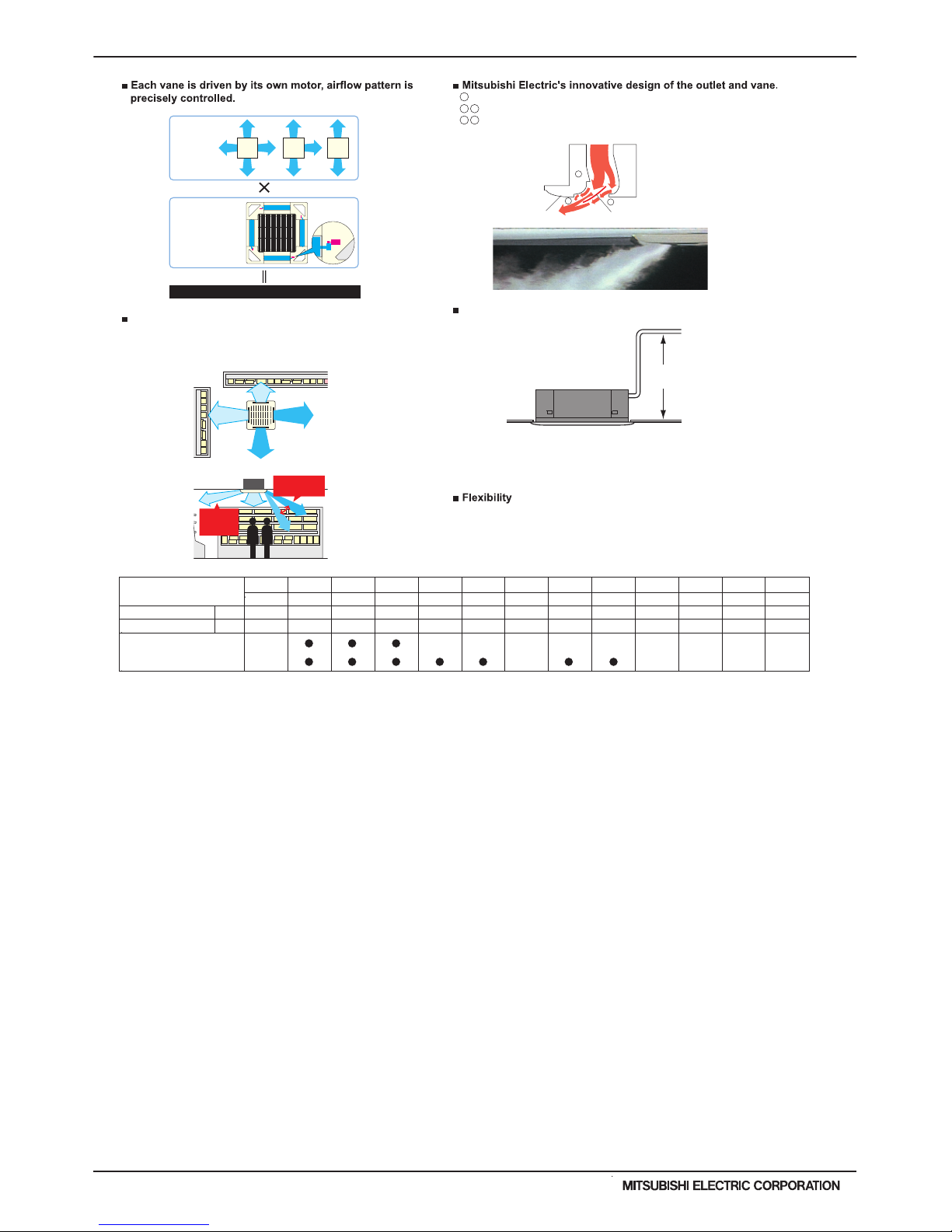
Various airflow pattern to meet your needs, strong airflow power, suitable for ceiling of max.13 -9" height
4-, 3-, or
2-way
outlet
selection
Fixed airflow
direction per
vane
Motor
for the
vane
72 airflow patterns
850mm
(33-
7
/16 in.)
Fixed
Fixed
Fixed
Fixed
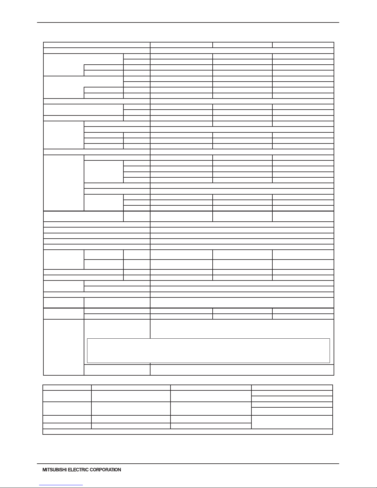
Refrigerated
showcase not
affected by air
conditioning
Top or bottom
airflow setting via
remote controller
1
2
3
Outside Inside
Grille Vane
Example (Convenient chain store)
Airflow doesn't disturb the cooled air in show-case
helps energy saving.
1 Uniformly distribute the air onto the louver.
2 3 Avoid airflow rising up.
2 3 Avoid dust attachment.
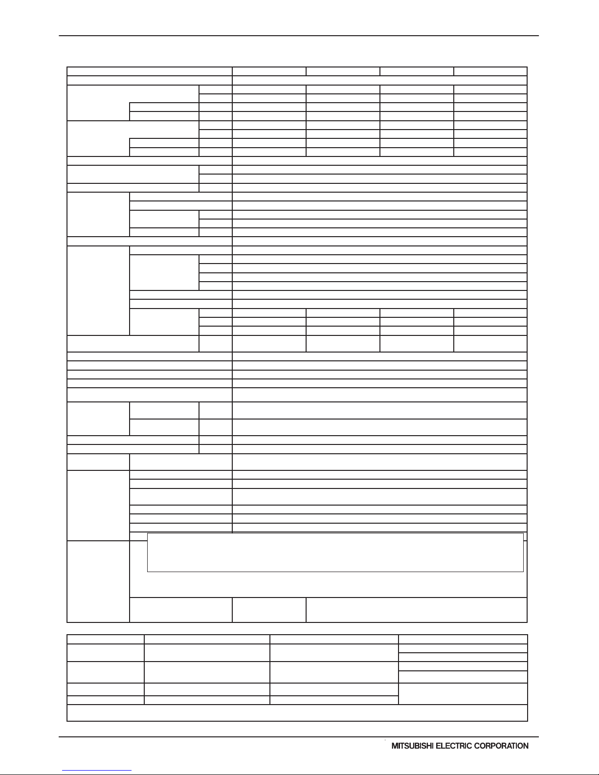
Allowing long piping and versatility.
The PLFY not only brings outside air into your space, but the PLFY-P-NBMU-E2
can also branch over to air-condition an adjacent room.
Drain water lifted to 33-7/16” (PLFY-P-NBMU-E2) or 19-11/16” (PLFY-P-NCMU-E2)
Precise airflow pattern on PLFY-P-NBMU-E2
(on PLFY-P-NBMU-E2)
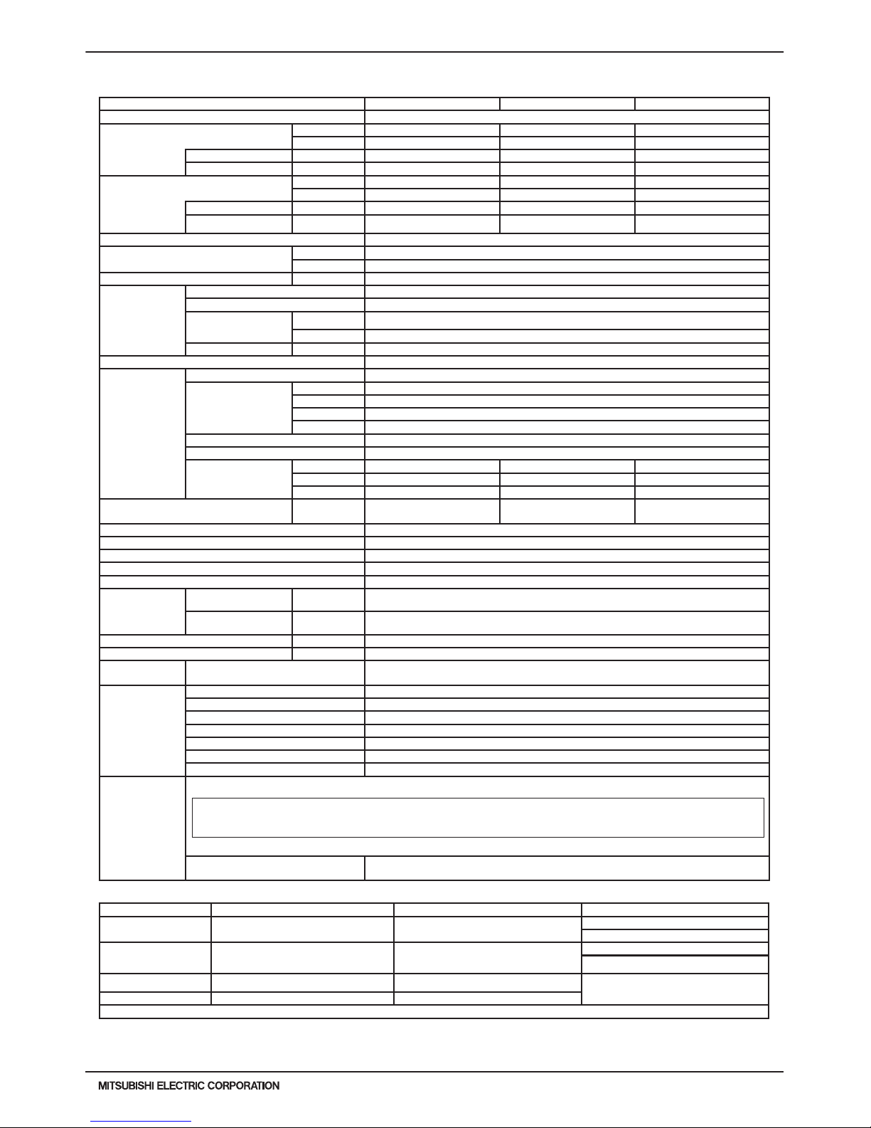
PLFY-P-NBMU-E2
PLFY-P-NBMU-E
PLFY-P-NCMU-E
PLFY-P-NBMU-E2
PLFY-P-NCMU-ER4
3.2HP 8.0HP4.0HP 5.0HP
P08 P12 P15 P18 P30 P36 P48P06 P24 P27 P54 P72
10.0HP
P96
0.8HP 1.0HP 1.3HP 1.6HP 2.0HP 2.5HP 2.8HP 5.6HP
Cassette ceiling
48,000
6,700
Nominal cooling cap.*1
Nominal heating cap.*2
6,000 8,000 12,000 15,000 18,000 24,000 27,000 30,000 36,000 54,000 72,000 96,000
60,000 80,000 108,00027,000 30,000 34,000 40,000 54,0009,000 13,500 17,000 20,000
Btu/h
Btu/h
* Nominal conditions *1, *2 are referred to in the Specification sheet.
PLFY-3PLFY-P-NCMU-ER4, -NBMU-E2 (November 2015)
© 2015 Mitsubishi Electric US, Inc.
Model PLFY-P08NCMU-ER4 PLFY-P12NCMU-ER4 PLFY-P15NCMU-ER4
Power source 1-phase 208-230 V 60Hz
Cooling capacity *1
(Nominal)
Btu/h 8,000 12,000 15,000
kW 2.3 3.5 4.4
Power input kW 0.05 0.06 0.06
Current input A 0.23 0.28 0.28
Heating capacity *2
(Nominal)
Btu/h 9,000 13,500 17,000
kW 2.6 4.0 5.0
Power input kW 0.05 0.06 0.06
Current input A 0.23 0.28 0.28
External nish Galvanized Steel Sheet
External dimension H x W x D
in. 8-3/16 x 22-7/16 x 22-7/16 8-3/16 x 22-7/16 x 22-7/16 8-3/16 x 22-7/16 x 22-7/16
mm 208 x 570 x 570 208 x 570 x 570 208 x 570 x 570
Net weight lbs (kg) 34 (15.5) 37 (17) 37 (17)
Decoration
panel
Model SLP-15AAUW SLP-15AAUW SLP-15AAUW
External nish Munsell No. 6.4Y 8.9/0.4
Dimension in. 25/32 x 25-19/32 x 25-19/32 25/32 x 25-19/32 x 25-19/32 25/32 x 25-19/32 x 25-19/32
H x W x D mm 20 x 650 x 650 20 x 650 x 650 20 x 650 x 650
Net Weight lbs (kg) 7(3) 7(3) 7(3)
Heat exchanger Cross n
Fan
Type x Quantity Turbo fan x 1 Turbo fan x 1 Turbo fan x 1
External
static pressure
in.WG 0.000 (208V) 0.000 (208V) 0.000 (208V)
Pa 0 0 0
in.WG 0.000 (230V) 0.000 (230V) 0.000 (230V)
Pa 0 0 0
Motor type 1-phase induction motor
Driving mechanism Direct-driven
Airow rate
(Low-Mid-High)
CFM 280-320-350 320-350-390 320-350-390
m3 / min 8.0-9.0-10.0 9.0-10.0-11.0 9.0-10.0-11.0
L / s 133-150-167 150-167-183 150-167-183
Sound pressure level (Low-Mid-High)
(measured in anechoic room)
dB <A> 29-32-38 (208-230V) 30-34-39 (208-230V) 31-35-40(208-230V)
Insulation material Polyethylene foam
Air lter Polypropylene honeycomb fabric
Protection device Fuse
Refrigerant control device LEV
Connectable outdoor unit R410A,R22 CITY MULTI
Diameter of
refrigerant pipe
(O.D.)
Liquid (R410A) in. (mm) 1/4 (6.35) Flare 1/4 (6.35) Flare 1/4 (6.35) Flare
Gas (R410A) in. (mm) 1/2 (12.7) Flare 1/2 (12.7) Flare 1/2 (12.7) Flare
Field drain pipe size in. (mm) O.D. 1-1/4(32) O.D. 1-1/4(32) O.D. 1-1/4(32)
Drain Lift Mechanism in. (mm) 19-11/16 (500) 19-11/16 (500) 19-11/16 (500)
Drawing
External RG01N654
Wiring RG79V389
Refrigerant cycle -
Standard attachment
Document
Accessory
Installation Manual,Installation Book
Drain hose<1-1/4in.(32mm)>
Optional parts
External heater adapter CN24RELAY-KIT-CM3 CN24RELAY-KIT-CM3 CN24RELAY-KIT-CM3
Decoration panel SLP-15AAUW SLP-15AAUW SLP-15AAUW
Remark
*PLFY-P-NCMU-E should used together with SLP-15AAUW.
Installation
Details on foundation work, duct work, insulation work, electrical wiring, power source switch, and
other items shall be referred to the Installation Manual.
Ventilation Air: Providing sufcient ventilation air is an important part of every building design.
ASHRAE standard 62 provides the minimum ventilation air requirements. Also check local
codes.
1. SPECIFICATIONS
Note: *1 Nominal cooling conditions *2 Nominal heating conditions Unit converter
Indoor:
80degF D.B. / 67degF W.B.
(26.7degC D.B. / 19.4degC W.B.)
70degF D.B. (21.1degC D.B.)
kcal/h = kW x 860
BTU/h = kW x 3,412
Outdoor: 95degF D.B. (35degC D.B.)
47degF D.B. / 43degF W.B.
(8.3degC D.B. / 6.1degC W.B.)
cfm = m3/min x 35.31
lbs = kg / 0.4536
Pipe length: 25 ft. (7.6 m) 25 ft. (7.6 m)
*Above specication data is subject to
rounding variation.
Level difference: 0 ft. (0 m) 0 ft. (0 m)
*Due to continuing improvement, above specication may be subject to change without notice.
PLFY-P08NCMU-ER4, PLFY-P12NCMU-ER4, PLFY-P15NCMU-ER4
PLFY-4
PLFY-P-NCMU-ER4, -NBMU-E2 (November 2015)
© 2015 Mitsubishi Electric US, Inc.
Model PLFY-P08NBMU-E2 *3 PLFY-P12NBMU-E2 PLFY-P15NBMU-E2 PLFY-P18NBMU-E2
Power source 1-phase 208-230 V 60Hz
Cooling capacity *1
(Nominal)
Btu/h 8,000 12,000 15,000 18,000
kW 2.4 3.5 4.4 5.3
Power input kW 0.03 0.03 0.03 0.04
Current input A 0.31 0.31 0.31 0.33
Heating capacity *2
(Nominal)
Btu/h 9,000 13,500 17,000 20,000
kW 2.7 4.0 5.0 5.9
Power input kW 0.02 0.02 0.02 0.03
Current input A 0.24 0.24 0.24 0.26
External nish Galvanized steel sheet
External dimension H x W x D
in. 10-3/16 x 33-3/32 x 33-3/32
mm 258 x 840 x 840
Net weight lbs (kg) 51 (23)
Decoration
panel
Model PLP-40BAU
External nish Munsell No. (6.4Y 8.9/0.4)
Dimension
H x W x D
in. 1-3/8 x 37-13/32 x 37-13/32
mm 35 x 950 x 950
Net Weight lbs (kg) 13 (6)
Heat exchanger Cross n
FAN
Type x Quantity Turbo fan x 1
External static
pressure
in.WG 0.000 (208V)
Pa 0
in.WG 0.000 (230V)
Pa 0
Motor type DC motor
Driving mechanism Direct-driven
Airow rate (LowMid2-Mid1-High)
CFM 494 - 530 - 547 - 565 494 - 530 - 547 - 565 494 - 530 - 547 - 565 494 - 530 - 565 - 636
m3 / min 14.0 - 15.0 - 15.5 - 16.0 14.0 - 15.0 - 15.5 - 16.0 14.0 - 15.0 - 15.5 - 16.0 14.0 - 15.0 - 16.0 - 18.0
L / s 233 - 250 - 259 - 267 233 - 250 - 259 - 267 233 - 250 - 259 - 267 233 - 250 - 267 - 300
Sound pressure level (Low-Mid2-Mid1-High)
(measured in anechoic room)
dB <A>
27 - 29 - 30 - 31(208-
230V)
27 - 29 - 30 - 31(208-
230V)
28 - 29 - 30 - 31(208-
230V)
28 - 29 - 30- 32(208-
230V)
Insulation material PS
Air lter PP honeycomb (long life lter, anti-bacterial type)
Protection device Fuse
Refrigerant control device LEV
Connectable outdoor unit R410A CITY MULTI
Diameter of
refrigerant pipe
(O.D.)
Liquid (R410A) in. (mm) 1/4 (6.35) Flare
Gas (R410A)
in. (mm) 1/2 (12.7) Flare
Field drain pipe size in. (mm) O.D. 1-1/4(32)
Drain lift mechanism in. (mm) 33-7/16 (850)
Standard
attachment
Document
Accessory
Installation Manual, Instruction Book
Optional parts
External heater adapter CN24RELAY-KIT-CM3
Air outlet shutter plate PAC-SH51SP-E
High efciency lter element
(MERV 10)
PAC-SH59KF-E
Multi-function casement PAC-SH53TM-E
i-see sensor corner panel PAC-SA1ME-E
Flange for fresh air intake PAC-SH65OF-E
Wireless signal receiver PAR-SA9FA-E
Remark
Installation
Details on foundation work, duct work, insulation work, electrical wiring,
power source switch, and other items shall be referred to the Installation
Manual.
Ventilation Air: Providing sufcient ventilation air is an important part of every building design.
ASHRAE standard 62 provides the minimum ventilation air requirements. Also check local
codes.
1. SPECIFICATIONS
Note: *1 Nominal cooling conditions *2 Nominal heating conditions Unit converter
Indoor:
80degF D.B. / 67degF W.B.
(26.7degC D.B. / 19.4degC W.B.)
70degF D.B. (21.1degC D.B.)
kcal/h = kW x 860
BTU/h = kW x 3,412
Outdoor: 95degF D.B. (35degC D.B.)
47degF D.B. / 43degF W.B.
(8.3degC D.B. / 6.1degC W.B.)
cfm = m3/min x 35.31
lbs = kg / 0.4536
Pipe length: 25 ft. (7.6 m) 25 ft. (7.6 m)
*Above specication data is subject to
rounding variation.
Level difference: 0 ft. (0 m) 0 ft. (0 m)
*Due to continuing improvement, above specication may be subject to change without notice.
*3 PLFY-P08NBMU-E2 is not compatible with PUMY-P**NHMU/NKMU outdoor units.
PLFY-P08NBMU-E2, PLFY-P12NBMU-E2, PLFY-P15NBMU-E2, PLFY-P18NBMU-E2
PLFY-5PLFY-P-NCMU-ER4, -NBMU-E2 (November 2015)
© 2015 Mitsubishi Electric US, Inc.
Model PLFY-P24NBMU-E2 PLFY-P30NBMU-E2 PLFY-P36NBMU-E2
Power source 1-phase 208-230 V 60Hz
Cooling capacity *1
(Nominal)
Btu/h 24,000 30,000 36,000
kW 7.0 8.8 10.5
Power input kW 0.05 0.05 0.09
Current input A 0.47 0.50 0.87
Heating capacity *2
(Nominal)
Btu/h 27,000 34,000 40,000
kW 7.9 10.0 11.7
Power input kW 0.04 0.04 0.08
Current input A 0.40 0.43 0.80
External nish Galvanized steel sheet
External dimension H x W x D
in. 11-3/4 x 33-3/32 x 33-3/32
mm 298 x 840 x 840
Net weight lbs (kg) 60 (27)
Decoration
panel
Model PLP-40BAU
External nish Munsell No. (6.4Y 8.9/0.4)
Dimension
H x W x D
in. 1-3/8 x 37-13/32 x 37-13/32
mm 35 x 950 x 950
Net Weight lbs (kg) 13 (6)
Heat exchanger Cross n
Fan
Type x Quantity Turbo fan x 1
External
static pressure
in.WG 0.000 (208V)
Pa 0
in.WG 0.000 (230V)
Pa 0
Motor type DC motor
Driving mechanism Direct-driven
Airow rate
(Low-Mid2-Mid1-High)
CFM 565 - 636 - 706 - 777 565 - 636 - 742 - 812 777 - 883 - 989 - 1,059
m3 / min 16.0 - 18.0 - 20.0 - 22.0 16.0 - 18.0 - 21.0 - 23.0 22.0 - 25.0 - 28.0 - 30.0
L / s 267 - 300 - 333 - 367 267 - 300 - 350 - 384 367 - 417 - 467 - 500
Sound pressure level (Low-Mid2-Mid1-High)
(measured in anechoic room)
dB <A> 28 - 31 - 34 - 37(208-230V) 28 - 32 - 35 - 37(208-230V) 35 - 38 - 41 - 43(208-230V)
Insulation material PS
Air lter PP honeycomb (long life lter, anti-bacterial type)
Protection device Fuse
Refrigerant control device LEV
Connectable outdoor unit R410A CITY MULTI
Diameter of
refrigerant pipe
(O.D.)
Liquid (R410A) in. (mm) 3/8 (9.52) Flare
Gas (R410A) in. (mm) 5/8 (15.88) Flare
Field drain pipe size in. (mm) O.D. 1-1/4(32)
Drain lift mechanism in. (mm) 33-7/16 (850)
Standard
attachment
Document
Accessory
Installation Manual, Instruction Book
Optional parts
External heater adapter CN24RELAY-KIT-CM3
Air outlet shutter plate PAC-SH51SP-E
High efciency lter element (MERV 10) PAC-SH59KF-E
Multi-function casement PAC-SH53TM-E
i-see sensor corner panel PAC-SA1ME-E
Flange for fresh air intake PAC-SH65OF-E
Wireless signal receiver PAR-SA9FA-E
Remark
Installation
Details on foundation work, duct work, insulation work, electrical wiring, power source switch,
and other items shall be referred to the Installation Manual.
Ventilation Air: Providing sufcient ventilation air is an important part of every building design.
ASHRAE standard 62 provides the minimum ventilation air requirements. Also check local codes.
1. SPECIFICATIONS
Note: *1 Nominal cooling conditions *2 Nominal heating conditions Unit converter
Indoor:
80degF D.B. / 67degF W.B.
(26.7degC D.B. / 19.4degC W.B.)
70degF D.B. (21.1degC D.B.)
kcal/h = kW x 860
BTU/h = kW x 3,412
Outdoor: 95degF D.B. (35degC D.B.)
47degF D.B. / 43degF W.B.
(8.3degC D.B. / 6.1degC W.B.)
cfm = m3/min x 35.31
lbs = kg / 0.4536
Pipe length: 25 ft. (7.6 m) 25 ft. (7.6 m)
*Above specication data is subject to
rounding variation.
Level difference: 0 ft. (0 m) 0 ft. (0 m)
*Due to continuing improvement, above specication may be subject to change without notice.
PLFY-P24NBMU-E2, PLFY-P30NBMU-E2, PLFY-P36NBMU-E2
PLFY-6
PLFY-P-NCMU-ER4, -NBMU-E2 (November 2015)
© 2015 Mitsubishi Electric US, Inc.
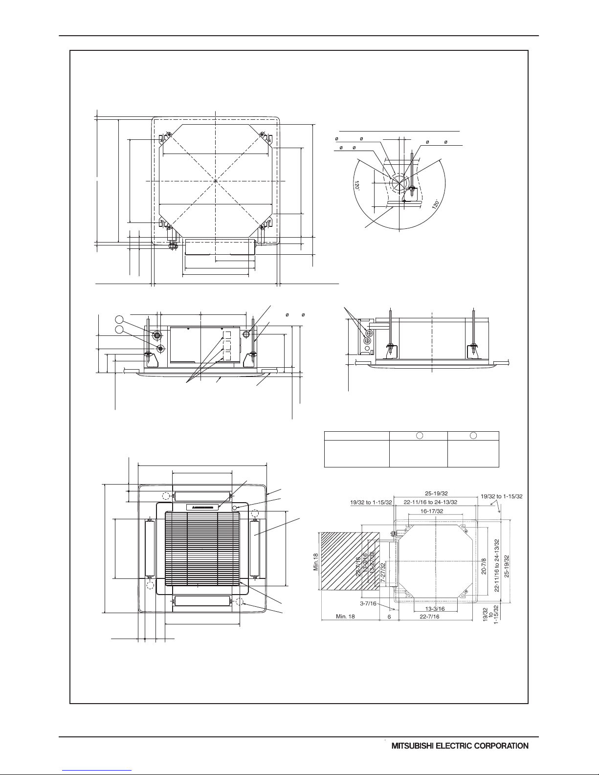
PLFY-P08,12,15 NCMU-ER4
PLFY-P15NCMU-ER4
PLFY-P12NCMU-ER4
PLFY-P08NCMU-ER4
Brand label
(1/2 (12.7) dia.)
1/2
flared connection
Refrigerant pipe
flared connection
1/4
Refrigerant pipe
(1/4 (6.35) dia.)
V/M
V/M
V/M
V/M
1
Detail drawing of fresh air intake
Ceiling surface
Cut out hole
2-7/8( 73.4)
Burring hole
3- 1/8( 2.8)
3-15/16( 100)
4-21/32(118)
1(25)
Unit : in.(mm)
19/32~1-15/32(15~37) 19/32~1-15/32(15~37)
22-11/16~24-13/32(576~620)
22-7/16(570)
20-7/8(530)
1
2
2
Grille
Fresh air intake
Drain pipe
VP-25 connection
(O.D. 1-1/4( 32))
Vane motor
Drain hole
Models
Air intake grille
2-5/32(55)
1-3/8(35)
1-3/8(35)
2-5/32(55)
Auto vane
Grille
Air intake hole
Air intake hole
Air outlet hole
Air outlet hole
11-27/32(301)
11-27/32(301)
14-27/32(377)
14-27/32(377)
25-19/32(650)
Suspension bolt M10 or W3/8
Suspension bolt lower edge
9-1/16(230)
7-5/32(182)1-7/8(48)
Wiring entry
Terminal block
Ceiling surface
9-1/4(235)
8-3/16(208)
7-19/32(193)
25/32(20)
3-21/32(93)
1-1/2~2-9/32(38~58)
2-19/32(66)
4-3/4(121)
7-15/16(202)
2-7/32(56)
2-1/14(57)
3-7/16(87)
1-7/32(31)
Ceiling hole
Suspension bolt pitch
19/32~1-15/32(15~37)
19/32~1-15/32(15~37)
22-11/16~24-13/32(576~620)
16-17/32(420)
22-7/16(570)
13-3/16(335)
7-27/32(199)
13-27/32(352)
13-3/16(335)
Suspension bolt pitch
Ceiling hole
25-19/32(650)
Ref. : PLFY-NCMU-E_EXD_USDB_P08-15
Unit : in.(mm)
1-1/16
+3/16
0
(
+5
)
0
2. EXTERNAL DIMENSIONS
Service Access Required
PLFY-7PLFY-P-NCMU-ER4, -NBMU-E2 (November 2015)
© 2015 Mitsubishi Electric US, Inc.
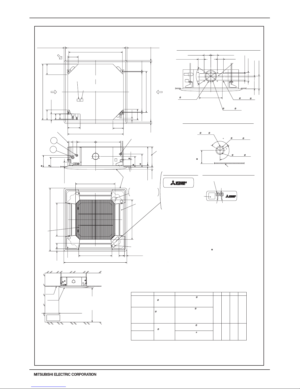
PLFY-P08, 12, 15, 18, 24, 30, 36 NBMU-E2
Unit : in. (mm)
14-27/3211-3/16
2-3/8
+5
0
+35
-5
(187.5)
(160)
(160)
(7.5)
(950)
(500)
Keep 25/64(10) to 19/32(15)
between unit ceiling
and ceiling slab.
Grille
Indoor unit
Ceiling
Floor
Min.94-1/2(2400)
from floor
Min.19-11/16(500)
Entire
periphery
(36)
(83)
(36)
(83)
(500)
(950)
(597)
(597)
( 158)
( 175)
(350)
(130)
(100)
(90)
(100)
(90)
(100)
(77)
3-1/32
(85)
3-11/32
(298)
11-3/4
11-1/16
(281)
(74)(80)(258)(241)
2-29/32
3-5/32
10-3/16
PLFY-P36NBMU-E2
PLFY-P24NBMU-E2
PLFY-P30NBMU-E2
(35)
(17 )
+3/16
0
(190)
(156)
(50~70)
(140)
(170)
(377)
(284)
(60)
(24)
(840)
(160)
(20~45)
to 1-25/32
(620)
(605 )
-3/16
+1-3/8
(90)
(150)
(160)
(7.5)
(20~45)
1-25/32
Corner pocket
In case of wireless remote controller
In case of standard grille
9-1/2
Drain hole
Drain pump clean hole
and Drain emergency
drainage hole
For MA-Remote controller
terminal block
Emergency operation switch<Cooling>
Emergency operation
switch<Heating>
Ceiling
Cut out hole
Burring hole pitch
3- 1/8(3- 2.8)
Burring hole
Detail drawing of fresh air intake hole
Burring hole
14- 1/8(14- 2.8)
Cut out hole
Burring hole pitch
Cut out hole
Detail connecting of branch duct(Both aspects)
Refrigerant pipe 15.88
Flared connection 5/8
(compatible)
DCBA
Refrigerant pipe 12.7
Flared connection 1/2
(compatible)
Refrigerant pipe
...
15.88
Flared connection
...
5/8
Refrigerant pipe
...
12.7
Flared connection
...
1/2
Refrigerant pipe
...
6.35
Flared connection
...
1/4
Refrigerant pipe
6.35
Flared connection
1/4
(compatible)
PLFY-P18NBMU-E2
Refrigerant pipe
...
9.52
Flared connection
...
3/8
Models
PLFY-P08NBMU-E2
PLFY-P12NBMU-E2
PLFY-P15NBMU-E2
Suspension bolt
lower edge
Vane motor
Air intake
grille
Air outlet hole
Air outlet hole
Auto vane
(Air outlet)
Air intake hole
Air intake hole
Grille
Ceiling
)(
Connected the attached
flexible pipe or socket.
I.D.1(26)
Integrated lift pump outlet
PVC pipe O.D.1(26)
Suspension bolt
M10 or W3/8
Branch duct hole
Fresh air
intake hole
Branch
duct hole
Ceiling hole
Suspension bolt pitch
Suspension bolt pitch
Ceiling hole
(5/16)(5/16)
23-13/16
24-13/32
DEFROST/STAND BY lamp
Receiver
Operation lamp
6-5/16
6-16/5
1
2
3-15/16
5-1/8
13-25/32
3-17/32
3-15/16
3-15/16
3-17/32
70
*6-9/16(167)
*6-3/32(155)
5-29/32( 150)
6-7/8
19-11/16
19-11/16
23-1/2
M
M
M
M
3-17/64
1-27/64
37-3/8
3-17/64
1-27/64
37-3/8
23-1/2
1-31/32 to 2-3/4
5-1/2
6-11/16
1-3/8
11/16
4-1/8(105)
6-9/64
7-15/32
A
B
6-5/16
33-1/16(840)
5-29/32
3-17/32
C
D
33-1/16
7-3/8
25/32~1-25/32(20~45)
33-27/32 to 35-13/16(860~910) 25/32 to 1-25/32(20~45)
31-7/8(810)
25/32 to
33-27/32 to 35-13/16(860~910)25/32
15/16
6-5/16
Indoor unit/Outdoor unit
connecting terminal block
4-29/32( 125)
3-15/16( 100)
6-7/32
120
120
12
Note:
1. As for drain pipe, please use VP-25 O.D. 1-1/4(32) PVC TUBE.
Drain pump is included.
Max. lifting height is 33-7/16 (850mm) from the ceiling.
2. As for suspension bolt, please use M10 or W3/8. (Procured at local site)
3. Electrical box may be removed for the service purpose.
Make sure to slack the electrical wire little bit for control/power wires connection.
4. The height of the indoor unit is able to be adjusted with the grille attached.
5. For the installation of the optional high efficiency filter or optional multi-functional
casement.
1 Add 5-5/16"(135mm) to the dimensions marked on the figure.
2 The optional high efficiency filter becomes optional multi-functional casement
and concomitant use.
6. When installing the branch ducts, be sure to insulate adequately.
Otherwise condensation and dripping may occur.
(It becomes the cause of dew drops/water dew.)
As for necessary installation / service space, please refer to the left figure.
Accessory∙∙∙Drain socket(I.D.1-1/4(32) )
Flare nut 3/8 (For P18)
Flare nut 5/8 (For P18)
Flare nut 3/4 (For P36)
2. EXTERNAL DIMENSIONS
PLFY-8
PLFY-P-NCMU-ER4, -NBMU-E2 (November 2015)
© 2015 Mitsubishi Electric US, Inc.
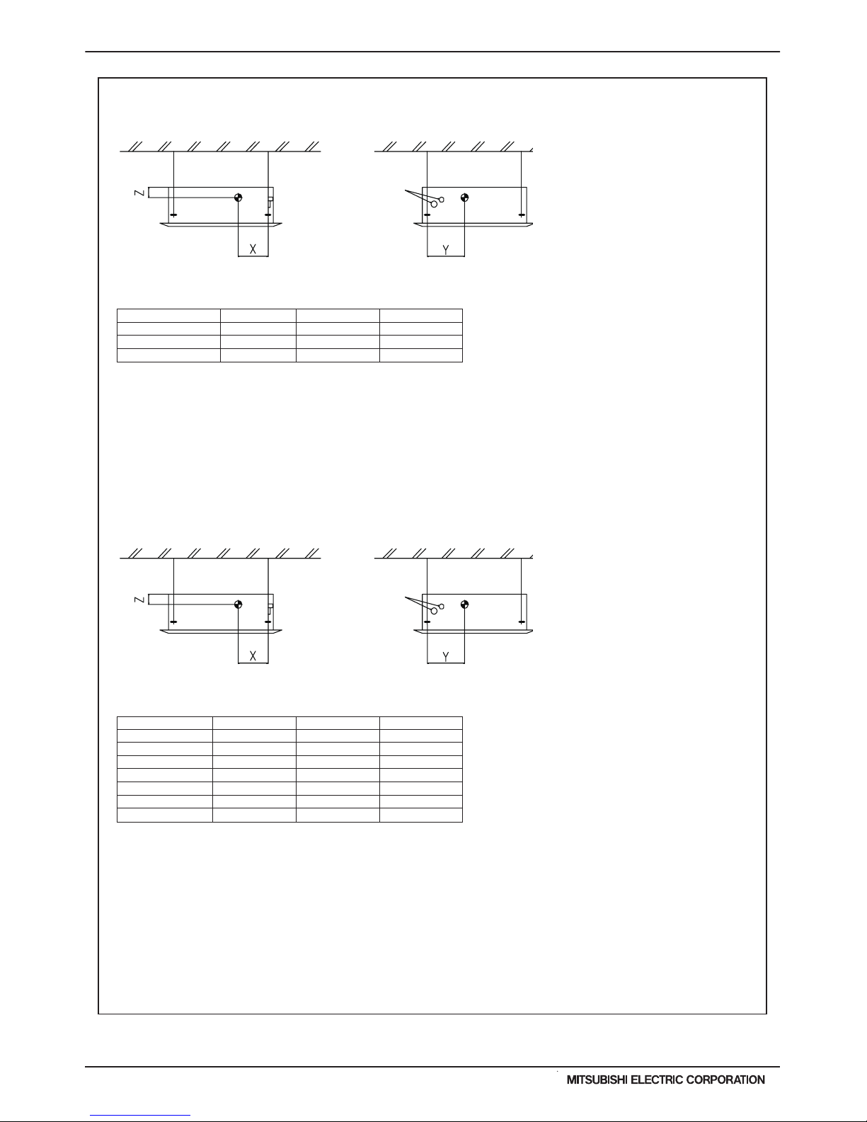
3. CENTER OF GRAVITY
PLFY-P08, 12, 15NCMU-E
PLFY-P08, 12, 15, 18, 24, 30, 36NBMU-E2
150 [5-29/32] 260 [10-1/4] 105 [4-5/32]
150 [5-29/32] 260 [10-1/4] 105 [4-5/32]
150 [5-29/32] 260 [10-1/4] 105 [4-5/32]
PLFY-P08NCMU-E
PLFY-P12NCMU-E
PLFY-P15NCMU-E
XY Z
(mm)[in]
Model name
280 [11-1/32] 400 [15-3/4] 105 [4-5/32]
280 [11-1/32] 400 [15-3/4]
105 [4-5/32]
280 [11-1/32]
280 [11-1/32]
280 [11-1/32]
280 [11-1/32]
400 [15-3/4]
400 [15-3/4]
400 [15-3/4]
400 [15-3/4]
105 [4-5/32]
125 [4-15/16]
125 [4-15/16]
125 [4-15/16]
PLFY-P12NBMU-E2
280 [11-1/32] 400 [15-3/4] 105 [4-5/32]PLFY-P08NBMU-E2
PLFY-P15NBMU-E2
PLFY-P18NBMU-E2
PLFY-P24NBMU-E2
PLFY-P30NBMU-E2
PLFY-P36NBMU-E2
XY Z
(mm)[in]
Model name
Refrigerant pipe side
Refrigerant pipe
Refrigerant pipe side
Refrigerant pipe
Refrigerant pipe side
Refrigerant pipe
PLFY-P08,12,15NCMU-ER4
Ref.: PLFY_NCMU_COG_USDB_ALL
150 [5-29/32] 260 [10-1/4] 105 [4-5/32]
150 [5-29/32] 260 [10-1/4] 105 [4-5/32]
150 [5-29/32] 260 [10-1/4] 105 [4-5/32]
PLFY-P08NCMU-ER4
PLFY-P12NCMU-ER4
PLFY-P15NCMU-ER4
XY Z
(mm)[in]
Model name
Refrigerant pipe side
Refrigerant pipe
PLFY-9PLFY-P-NCMU-ER4, -NBMU-E2 (November 2015)
© 2015 Mitsubishi Electric US, Inc.
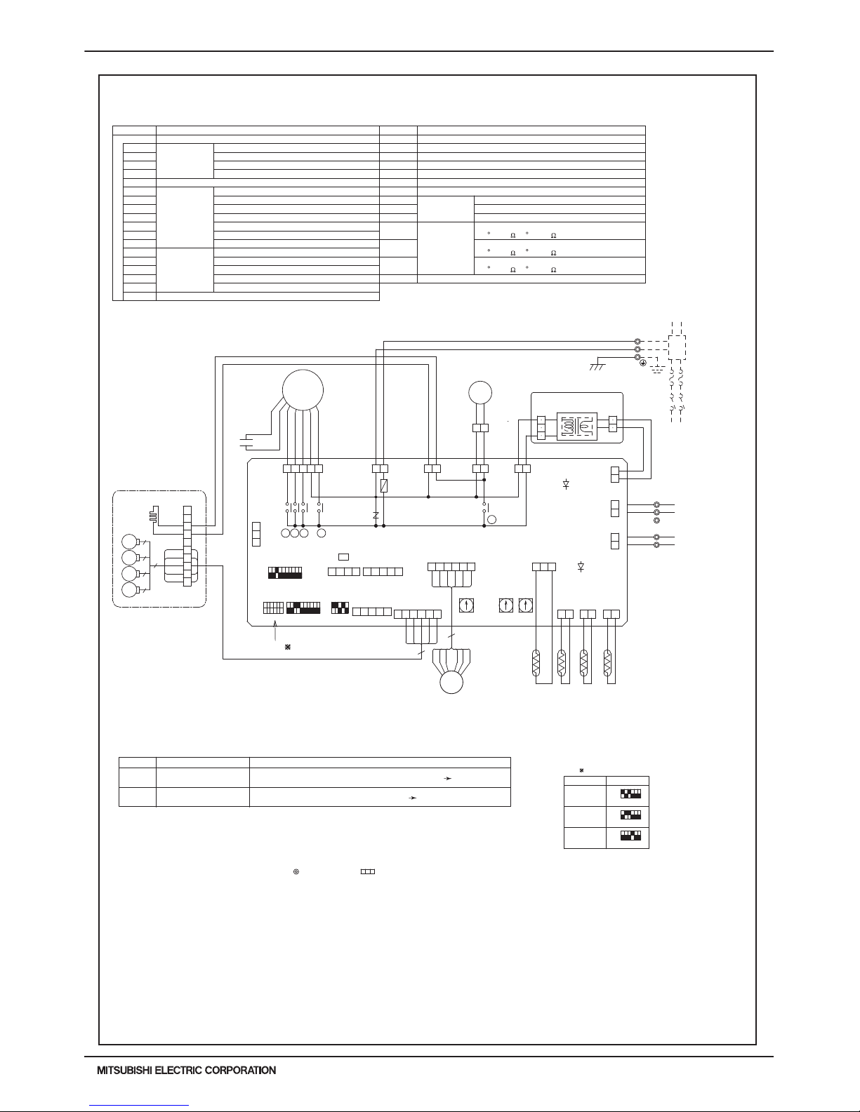
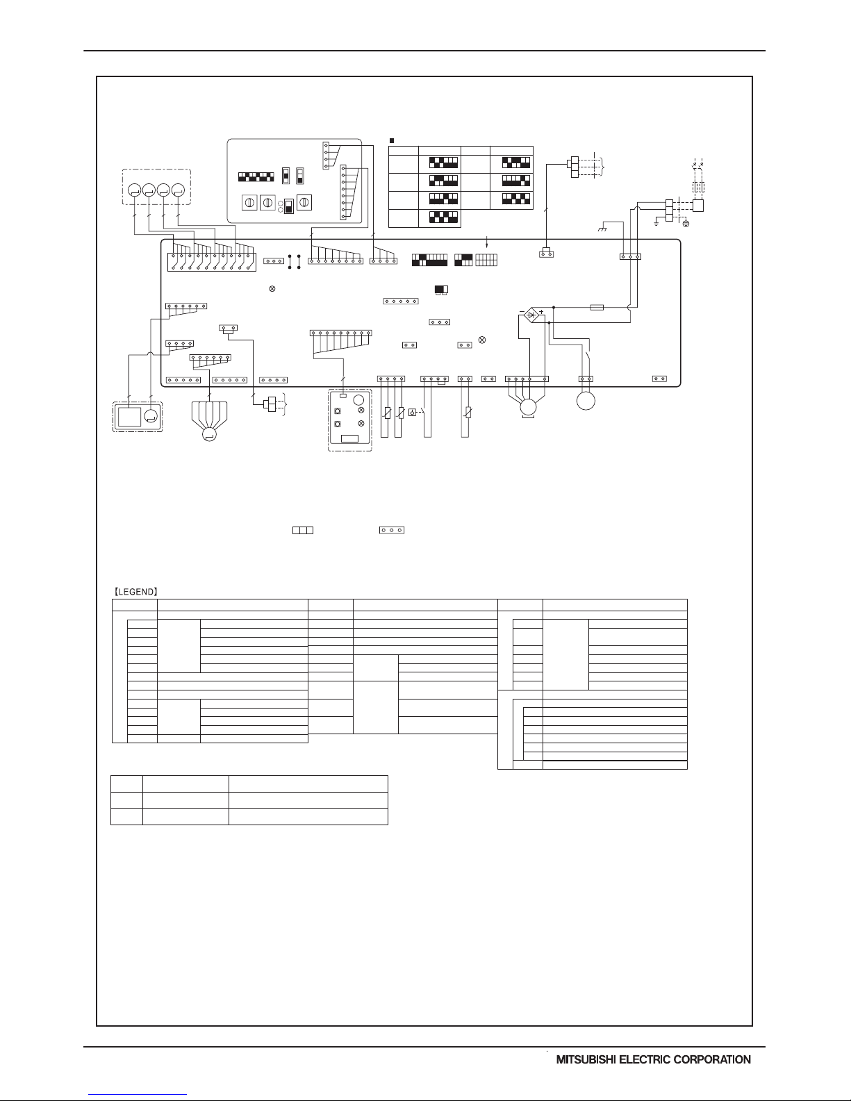
Ref. : PLFY-NCMU-E_EWD_USDB_P08-15
PLFY-P08,12,15 NCMU-ER4
DP
WHT
(DRAIN)
WHT
FAN
(FAN)
See fig: 1
MODELS
P08
P12
P15
<fig: 1>
ON
OFF
12 34 56
ON
OFF
12 34 56
ON
OFF
12 34 56
SW2
Power supply for MA-Remote controller on Lamp is lit.
Main power supply(Indoor unit:208-230V) power on Lamp is lit.Main power supply
LED2
LED1
Mark Meaning
LED on indoor controller board for service
Function
CN32
(REMOTE SWITCH)
WHT
3 2 1
DC24-30V
CONTROLLER
TO NEXT INDOOR UNIT
PULL BOX
FUSE(15A)
BREAKER
(15A)
60Hz
HA
1234
WHT
CN41
CN51
WHT
(CENTRALLY
CONTROL)
5 4 3 2 1
CN52
(REMOTE
INDICATION)
GRN
12345
REMOTE SWITCHCN32
X7 FAN MOTOR (Me)
X6 FAN MOTOR (Hi)
X5 FAN MOTOR (Lo)
SW1 SWITCH MODE SELECTION
CONNECTION No.SW14
SW12
SW11 ADDRESS SETTING 1ST DIGIT
ADDRESS SETTING 2ND DIGIT
MODEL SELECTION
MODE SELECTION
CAPACITY CODE
SW4
SW3
SW2
(32 F/15k 77 F/5.4k )
(32 F/15k 77 F/5.4k )
DP
DRAIN PUMP
DS
DRAIN SENSOR
H2
DEW PREVENTION HEATER
FAN MOTOR (LL)
DRAIN PUMP/DEW PREVENTION HEATERX1 AUX. RELAY
SYMBOL NAME
VARISTOR
INDOOR POWER BOARD
P.B
ZNR
X4
I.B
CN41
CN51
CN52
FUSE FUSE (6.3A/250V)
REMOTE INDICATION
CENTRALLY CONTROL
HA TERMINAL-A
CONNECTOR
INDOOR CONTROLLER BOARD
[LEGEND]
NAMESYMBOL
PIPE TEMPERATURE DETECTION/GAS
TH23
TRANSMISSION
TERMINAL
BLOCK
POWER SUPPLY
TB5
TB15
TB2
(32 F/15k 77 F/5.4k )
THERMISTOR ROOM TEMPERATURE DETECTION
TH22
TH21
LEV
LINEAR EXPANSION VALVE
MV
MF
VANE MOTOR
FAN MOTOR (WITH THERMAL FUSE)
CAPACITOR (FAN MOTOR)
C1
PIPE TEMPERATURE DETECTION/LIQUID
MA-REMOTE CONTROLLER
LED2
LED1
31 1 3
CND
(POWER)
YLW
21
YLW
1 3
BLU
(D+U+M)
CNC
(D+HEATER)
RED
ORN
FUSE
ZNR
CNP
X1
RED
ORN
GRILLE
BLU
5
WHT
BLU
RED
ORN
YLW
RED
RED
1
10
7
2
3
6
4
5
8
9
3
5
5
5
5
C1
1 5
BLK
YLW
WHT
BRN
7 9
X6 X5 X4 X7
X4X7X5X6
MF
I.B
CN20
CN31
123
BLU
WHT
ORN
RED
YLW
6
6 5 4 3 2 1
(VANE)
CN6V
GRN
RED
ORN
BLU
6 5 4 3 2 1
(LEV)
CN60
WHT
WHT
YLW
BRN
BLK
2 2 11
(LIQUID)
(INTAKE)
CN21
RED WHT
2 1
(GAS)
CN29
(REMOCON)
WHT
13
RED
P.B
RED
CNDK
(POWER
BORD)
1
2
3
AC208-230V
CNSK(RED)
TB2
L1
L2
GR
RED
BLU
GRN/YLW
~/N 208-230V
POWER SUPPLY
TRANS
DC13.1V
CN2S(WHT)
2
1
2 1
(POWER
BORD)
CN2D
WHT
WHT
BLK
M1
1
2
CONTROLLER
DC8.7-13V
TO MA-REMOTE
CN2M
(M-NET)
123 1
CN3A
BLU
BLU
M2
TB15
S(SHIELD)
M-NET REMOTE
TO OUTDOOR UNIT
BC CONTROLLER
TB5
X1
TH23
TH22
TH21DS
LEV
5
3RD
DIGIT
0
O
0
0N
0FF
SW1
1 2 3 4 5 6 7 8 9 10
SW12
SW11
1ST
DIGIT
0
2ND
DIGIT
SW14
CONNECTION
No.
1 2 3 4 5
0FF
0N
SW4
SW2
654321 10987654321
0FF
0N
SW3
MV
H2
MV
MV
MV
Notes:
2.In case of using MA-Remote controller, please connect to TB15. (Remote controller wire is non-polar.)
3.In case of using M-NET, please connect to TB5. (Transmisson line is non-polar.)
4.Symbol[S] of TB5 is the shield wire connection.
5.Symbols used in wiring diagram above are, :terminal block, :connecter.
7.Use copper supply wire.
6.The setting of the SW2 dip switches differs in the capacity for the detail, refer to the fig:1.
1.At servicing for outdoor unit, always follow the wiring diagram of outdoor unit.
Power supply for
MA-Remote controller
4. ELECTRICAL WIRING DIAGRAMS
PLFY-10
PLFY-P-NCMU-ER4, -NBMU-E2 (November 2015)
© 2015 Mitsubishi Electric US, Inc.
PLFY-P08, 12, 15, 18, 24, 30, 36NBMU-E2
NOTES:
1. At servicing for outdoor unit, always follow the wiring diagram of outdoor unit.
2. In case of using MA-Remote controller, please connect to TB15. (Remote controller wire is non-polar.)
3. In case of using M-NET, please connect to TB5. (Transmission line is non-polar.)
4. Symbol [S] of TB5 is the shield wire connection.
5. Symbols used in wiring diagram above are, : terminal block, : connecter.
6. The setting of the SW2 dip switches differs in the capacity. For the detail, refer to fig <*1>.
CN27
CN32
CN51
CN52
SW2
SW3
SW4
SWE
FUSE
X1
LED1
LED2
MF
MV
DP
FS
TB2
TB5
TB15
TH21
TH22
TH23
LEV
SW1
SW11
SW12
SW14
SWA
SWB
SWC
W.B
RU
BZ
LED1
LED2
SW1
SW2
POWER SUPPLY
TRANSMISSION
MA-REMOTE CONTROLLER
ROOM TEMP. DETECTION
PIPE TEMP. DETECTION / LIQUID
PIPE TEMP. DETECTION / GAS
FAN MOTOR
VANE MOTOR
DRAIN PUMP
DRAIN FLOAT SWITCH
TERMINAL
BLOCK
THERMISTOR
LINEAR EXPANSION VALVE
I. B
Mark
LED1
Main power supply
Power supply for
MA-Remote controller
Main Power supply (Indoor unit:208-230V)
power on → lamp is lit
Power supply for MA-Remote controller
on → lamp is lit
LED2
Meaning Function
INDOOR CONTROLLER BOARD
CONNECTOR
DAMPER
EXTERNAL HEATER
REMOTE SWITCH
CENTRALLY CONTROL
REMOTE INDICATION
CAPACITY CODE
MODE SELECTION
MODEL SELECTION
DRAIN PUMP (TEST MODE)
SWITCH
FUSE (T6.3AL250V)
AUX. RELAY
POWER SUPPLY (I. B)
POWER SUPPLY (I. B)
DRAIN PUMP
SYMBOL
A. B
OPTION PART
ADDRESS BOARD
SWITCH
MODE SELECTION
ADDRESS SETTING 1s DIGIT
ADDRESS SETTING 10ths DIGIT
BRANCH NO.
CEILING HEIGHT SELECTOR
DISCHARGE OUTLET NUMBER
SELECTOR
OPTION SELECTOR
PCB FOR WIRELESS REMOTE CONTROLLER
RECEVING UNIT
BUZZER
LED (OPERATION INDICATION : GREEN)
LED (PREPARATION FOR HEATING : ORANGE)
EMERGENCY OPERATION (HEAT / DOWN)
EMERGENCY OPERATION (COOL / UP)
SYMBOLNAME NAME
LED on indoor board for service
CN24
SYMBOL NAME
MT
I-SEE SENSOR MOTOR
CN105
IT TERMINAL
(32°F/15kΩ, 77°F/5.4kΩ)
(32°F/15kΩ, 77°F/5.4kΩ)
(32°F/15kΩ, 77°F/5.4kΩ)
19
*Be sure to turn off the source power
and then disconnect fan motor connector.
(Failure to do so will cause trouble in Fan motor)
A.B
(RED)
ADDRESS
CN43
ADDRESS
CN81
(RED)
LED2
ADDRESS
CN42
(RED)
(RED)
ADDRESS
CN82
VANE
CNV
(WHT)
SWBSWA
SW1
MV MV MV MV
CN32
(WHT)
SW3 SW4
SWE
SW2
ON
OFF
ON
OFF
ON
OFF
ONOFF
9
6
54
8
5555
4
3
2
1
12345678910
12345612345
GRILLE
2
3
4
See fig: *1
*2
M-NET
CN2M
(BLU)
CND
(BLK)
CNAC
(WHT)
D.U.M
CNP
(BLU)
FAN
CNMF
(WHT)
INTAKE
CN20
(RED)
CN25
(WHT)
FLOAT SW
CN4F
(WHT)
WIRELESS
CN90
(WHT)
LEV
CN60
(WHT)
WHT
YLW
ORN
BLU
RED
BRN
MA REMOCON
CN3A
(BLU)
I-SEE SENSOR
CN4Y
(WHT)
I-SEE SENSOR MOTOR
CN6Y
(RED)
LIQUID/GAS
CN44
(WHT)
CN41
(WHT)
CN51
(WHT)
CN52
(GRN)
CN3G
(BLK)
TH21TH23TH22 FS
CN27
(RED)
LED1
X1
FUSE
TB5
(SHIELD)
TB2
RED
BLU
GRN/YLW
TO OUTDOOR UNIT
BC CONTROLLER
REMOTE CONTROLLER
24-30V DC
TO NEXT
INDOOR UNIT
PULL BOX
FUSE(16A)
BREAKER
(16A)
POWER SUPPLY
~/N 208-230V 60Hz
I.B
DC311~339V
RECTIFICATION
BZ
LEV
MT
LED2
SW1
CNB
TO MA-REMOTE
CONTROLLER
8.7-13V DC
I-SEE SENSOR CORNER PANEL
(OPTION PART)
(OPTION PART)
I-SEE
SENSOR
TB15
SW2
LED1
RU
W.B
Pair No.
J42 J41
2
2
14
1
2
1
4
1
8
1515
16
M
M
14
16
13
13
12345678910111213141516171819
20
ON
OFF
1 23456
ON
OFF
1 23456
ON
OFF
1 23456
ON
OFF
123456
ON
OFF
123456
ON
OFF
123456
P12
MODELS MODELS
<*1>
SW2 SW2
P15
P18
P24
P30
P36
ON
OFF
1 23456
P08
t° t°
14
14
21
CN24
(YLW)
21
31
2121
74
1
1313
3~
MF
MS
M
1~
21
135
L1
L2
GR
M1
M2
S
M M M M
1418
CN105
(RED)
15
DP
is the switch position.
t°
12345678910
*2. Use copper supply wires.
*2. Utilisez des fils d’alimentation en cuivre.
0
1
2
3
4
5
6
7
8
9
A
B
C
D
E
F
0
1
2
3
4
5
6
7
8
9
0
1
2
3
4
5
6
7
8
9
10ths
DIGIT
1s
DIGIT
BRANCH
No.
SWC
SW12 SW11
SW14
2
1
4. ELECTRICAL WIRING DIAGRAMS
 Loading...