

Mitsubishi PLFY-P08NCMU-E, PLFY-P12NCMU-E, PLFY-P15NCMU-E Service Manual
SPLIT-TYPE, HEAT PUMP AIR CONDITIONERS
TECHNICAL & SERVICE MANUAL
R410A / R22
Indoor unit
[Model names]
PLFY-P08NCMU-E
PLFY-P12NCMU-E
PLFY-P15NCMU-E
[Service Ref.]
PLFY-P08NCMU-E.TH
PLFY-P08NCMU-E1.TH
PLFY-P08NCMU-ER2.TH
PLFY-P08NCMU-ER3.TH
PLFY-P08NCMU-ER4.TH
PLFY-P12NCMU-E.TH
PLFY-P12NCMU-E
1.TH
PLFY-P12NCMU-ER2.TH
PLFY-P12NCMU-ER3.TH
PLFY-P12NCMU-ER4.TH
PLFY-P15NCMU-E.TH
PLFY-P15NCMU-E
1.TH
PLFY-P15NCMU-ER2.TH
PLFY-P15NCMU-ER3.TH
PLFY-P15NCMU-ER4.TH
Revision:
• PLFY-P08/12/15NCMU-ER4.TH
• Some descriptions have been
• Please void OCH410
NOTE:
• This manual describes only
April 2012
No. OCH410
REVISED EDITION-D
have been added in
REVISED EDITION-D.
modified.
REVISED EDITION-C.
service data of the indoor units.
Model name
indication
INDOOR UNIT
CONTENTS
1. TECHNICAL CHANGES
2. FEATURES
3. PART NAMES AND FUNCTIONS
4. SPECIFICATIONS
5. 4-WAY AIR FLOW SYSTEM
6. OUTLINES AND DIMENSIONS
7. WIRING DIAGRAM
8.
REFRIGERANT SYSTEM DIAGRAM
9. MICROPROCESSOR CONTROL
10. TROUBLESHOOTING
11. DISASSEMBLY PROCEDURE
................................................................
...........................................
.....................................................
......................................
..................................................
.............................................
PARTS CATALOG (OCB410)
.............................
...............................
........................
...........................
................................
2
3
4
6
9
11
12
15
16
23
30
Use the specifi ed refrigerant only
OCH410D
Never use any refrigerant other than that specifi ed.
Doing so may cause a burst, an explosion, or fi re when the unit is being used, serviced, or disposed of.
Correct refrigerant is specifi ed in the manuals and on the spec labels provided with our products.
We will not be held responsible for mechanical failure, system malfunction, unit breakdown or accidents caused
by failure to follow the instructions.
1
TECHNICAL CHANGES
PLFY-P08NCMU-ER3.TH PLFY-P08NCMU-ER4.TH
PLFY-P12NCMU-ER3.TH PLFY-P12NCMU-ER4.TH
PLFY-P15NCMU-ER3.TH PLFY-P15NCMU-ER4.TH
• INDOOR CONTROLLER BOARD (I.B) has been changed. (S/W version up)
PLFY-P08NCMU-ER2.TH PLFY-P08NCMU-ER3.TH
PLFY-P12NCMU-ER2.TH PLFY-P12NCMU-ER3.TH
PLFY-P15NCMU-ER2.TH PLFY-P15NCMU-ER3.TH
• TURBO FAN and WASHER have been changed.
PLFY-P08NCMU-E1.TH PLFY-P08NCMU-ER2.TH
PLFY-P12NCMU-E
1.TH PLFY-P12NCMU-ER2.TH
PLFY-P15NCMU-E1.TH PLFY-P15NCMU-ER2.TH
• The following functions of CONTROLLER BOARD (C.B) have been changed.
* Initial setting of auto restart function Not effective → effective (SW1-9 OFF → ON)
* External heating control change
PLFY-P08NCMU-E.TH PLFY-P08NCMU-E1.TH
PLFY-P12NCMU-E.TH PLFY-P12NCMU-E
PLFY-P15NCMU-E.TH PLFY-P15NCMU-E
• PANEL has been changed.
SLP-15AAU (White : 0.70Y 8.59/0.97) → SLP-15AAUW (Pure white : 6.4Y 8.9/0.4)
1.TH
1.TH
2
2
OCH410D
FEATURES
Models
Cooling capacity / Heating capacity
PLFY-P08NCMU-E 8,000 / 9,000 Btu/h
PLFY-P12NCMU-E 12,000 / 13,500 Btu/h
PLFY-P15NCMU-E 15,000 / 17,000 Btu/h
Indoor Unit
1. PERFECT PANEL SIZE
The brand new 22-7/16 inch PLFY-P08/12/15NCMU-E models are slim, attractive, yet powerful units.
PLFY-P08/12/15NCMU-E’s size and shape, which perfectly match 2-by-2 ceilings, and its lighter weight of 34 lbs
(PLFY-P08NCMU-E) make installation even easier and more convenient.
2. 29 dB WHISPER-QUIET OPERATION (PLFY-P08NCMU-E)
Ideal for cafés, bars, restaurants, and shops. Give all your customers the comfortable environment they deserve.
3. 2,500 HOUR LONG LIFE FILTER
Greatly reduces the frequency the filter needs to be replaced, making maintenance all the easier.
4. FRESH AIR INTAKE
Provides indoor air of the highest quality.
5. SMUDGE-FREE AIRFLOW
Reduces annoying drafts and smudging.
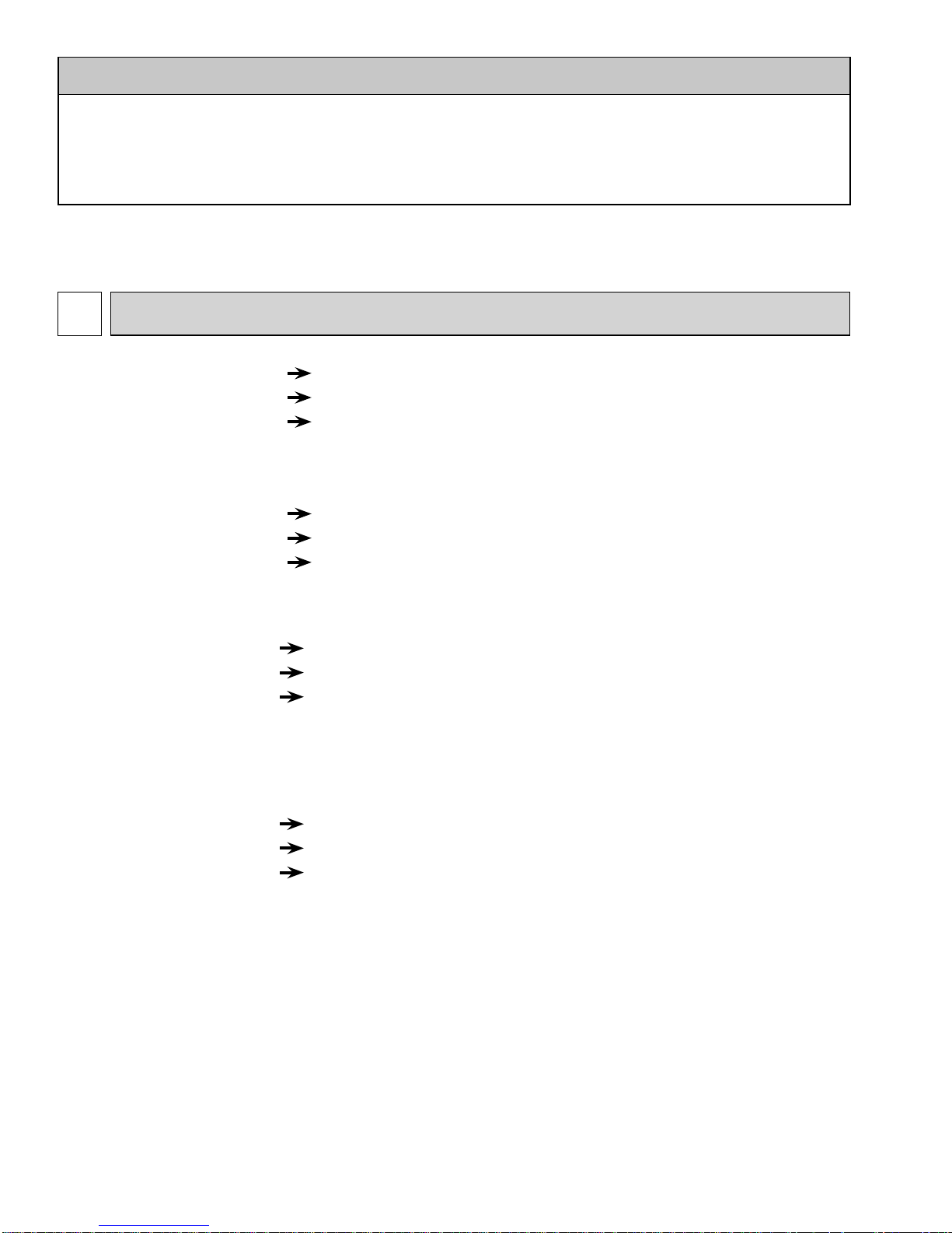
6. SLIM UNIT BODY FOR EASY INSTALLATION
The 22-7/16 inch slim body and octagonal shape, which make the distance between bolts only 16-17/32 inch, help installation easy and maintenance trouble-free.
Unit : inch
20-7/8
Suspension bolt pitch
16-17/32
Unit 22-7/16
22-7/16
T-bar
22-11/16
23-5/8
9-1/4
8-3/16
Ceiling surface
3
3
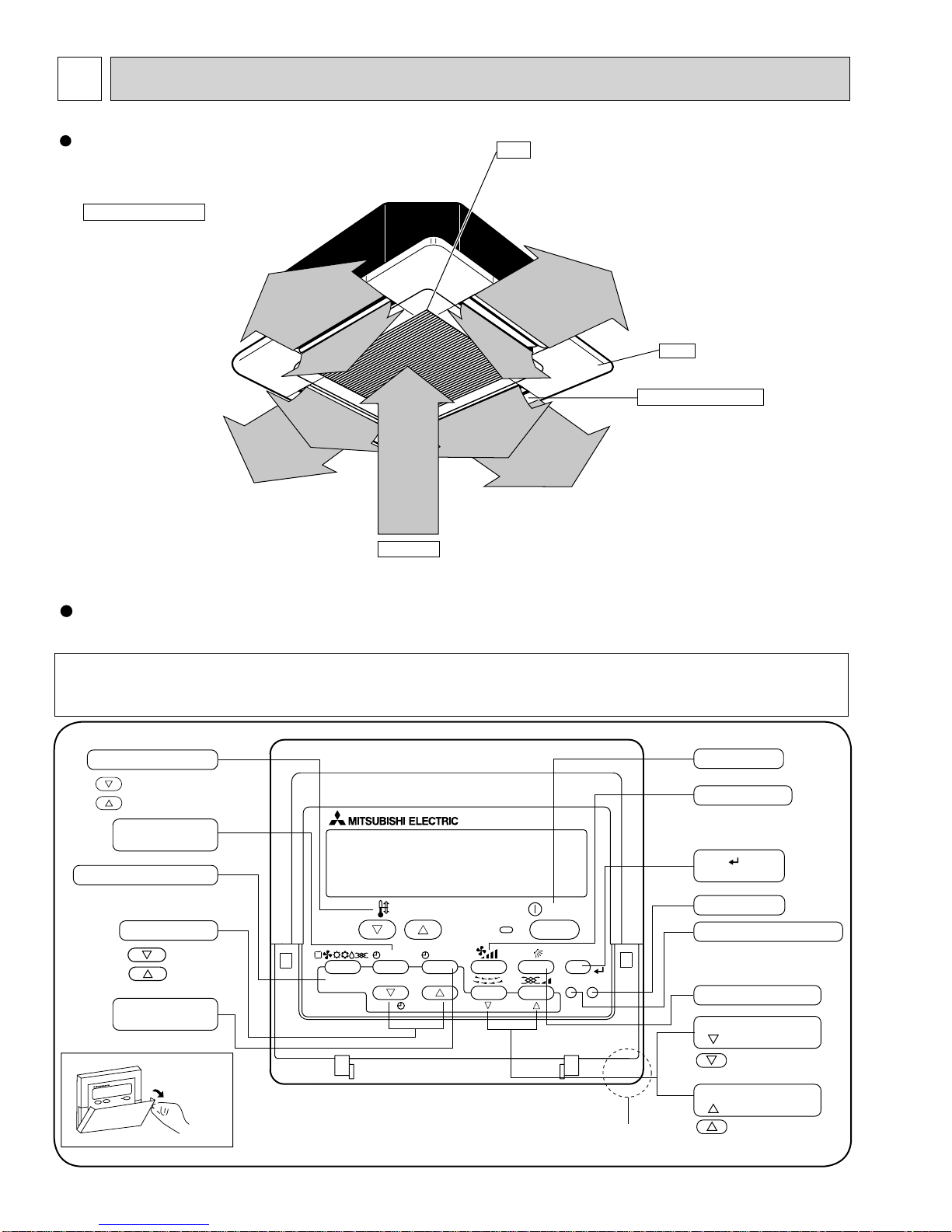
PAR-21MAA
ON/OFF
FILTER
CHECK
OPERATION
CLEAR
TEST
TEMP.
MENU
BACK DAY
MONITOR/SET
CLOCK
ON/OFF
Temperature setting buttons
Down
Up
Timer Menu button
(Monitor/Set button)
Mode button (Return button)
Set Time buttons
Back
Ahead
Timer On/Off button
(Set Day button)
Opening the
cover
ON/OFF button
Fan Speed button
Filter button
(<Enter> button)
Test Run button
Check button (Clear button)
Airflow Up/Down button
Louver button
( Operation button)
T o return operation
number
Ventilation button
( Operation button)
To go to next operation
number
Built-in temperature sensor
OCH410D
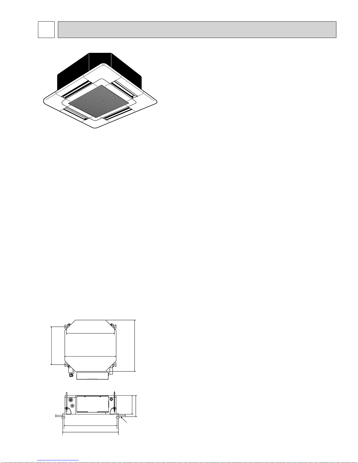
PART NAMES AND FUNCTIONS
Indoor (Main) Unit
Horizontal Air Outlet
Sets horizontal airflow automatically
during cooling or dehumidifying.
Filter
Removes dust and pollutants
from return air.
Grille
Auto Air Swing Vane
Disperses airflow up and
down and adjusts the angle
of airflow direction.
Air Intake
Returns air from room.
Wired remote controller
Once the controllers are set, the same operation mode can be repeated by simply pressing the ON/OFF button.
Note:
The phrase "Wired remote controller" in this manual refers only to the PAR-21MAA.
If you need any information for the other remote controller, please refer to either the installation manual or initial setting manual which are included in
remote controller's box.
4
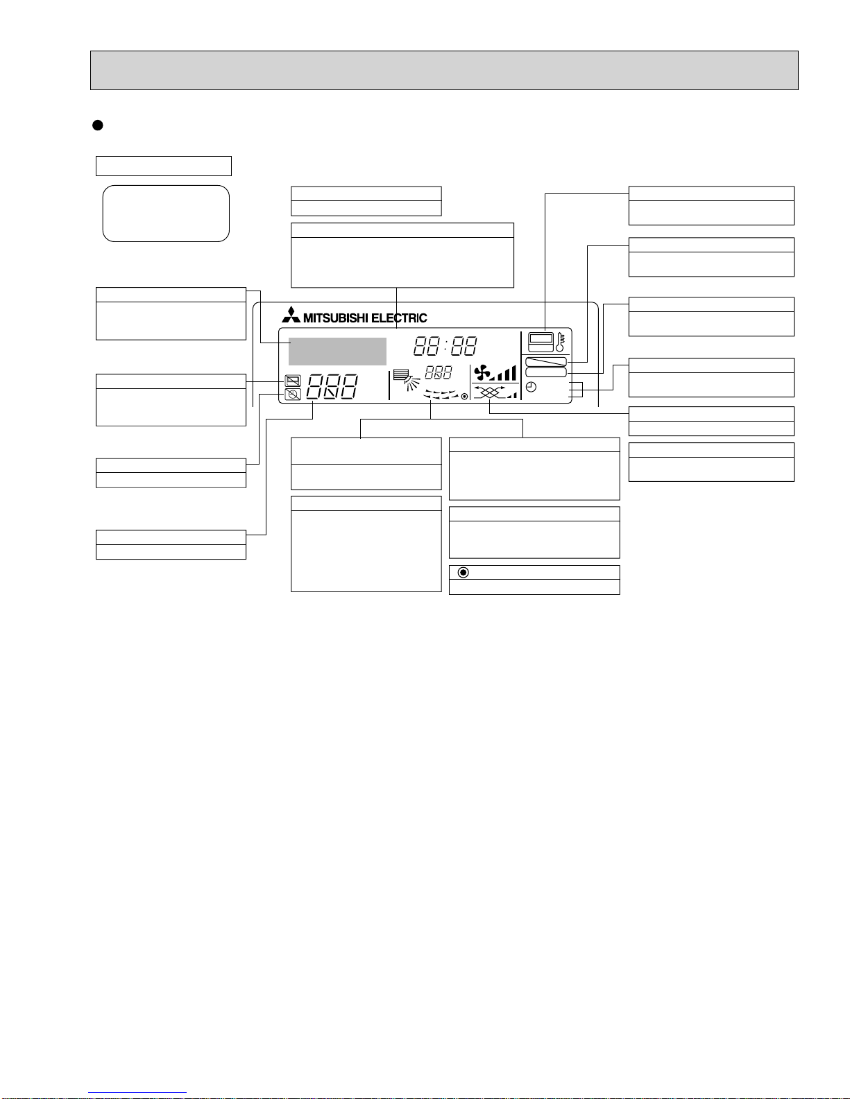
Wired remote controller
OCH410D
Display Section
For purposes of this explanation,
all parts of the display are shown
as lit. During actual operation, only
the relevant items will be lit.
Identifies the current operation
Shows the operating mode, etc.
*Multilanguage display is available.
“Centrally Controlled” indicator
Indicates that operation from the
remote controller has been prohibited by a master controller.
“Timer is Off” indicator
Indicates that the timer is off.
Temperature Setting
Shows the target temperature.
Day-of-Week
Shows the current day of the week.
Time/Timer Display
Shows the current time, unless the simple or Auto Off
timer is set.
If the simple or Auto Off timer is set, the time to be
switched off is shown.
TIME SUN MON TUE WED THU FRI SAT
TIMER
AFTER
ERROR CODE
°F°C
Hr
AFTER
°F°C
ONLY1Hr.
Up/Down Air Direction indicator
Shows the direction of the
outcoming airflow.
“One Hour Only” indicator
Displays if the airflow is set to
low or downward during COOL
or DRY mode. (Operation varies
according to model.)
The indicator goes off in one hour,
when the airflow direction also
changes.
Room Temperature display
Shows the room temperature. The room
temperature display range is 46~102°F.
The display blinks if the temperature
is less than
Louver display
Indicates the action of the swing louver.
Does not appear if the louver is not
running.
(Power On indicator)
Indicates that the power is on.
ON
OFF
FUNCTION
FILTER
WEEKLY
SIMPLE
AUTO OFF
46°F or 102°F
or more.
“Sensor” indication
Displays when the remote controller
sensor is used.
“Locked” indicator
Indicates that remote controller buttons have been locked.
“Clean The Filter” indicator
To be displayed on when it is time to
clean the filter.
Timer indicators
The indicator comes on if the corresponding timer is set.
Fan Speed indicator
Shows the selected fan speed.
Ventilation indicator
Appears when the unit is running in
Ventilation mode.
5
4
OCH410D
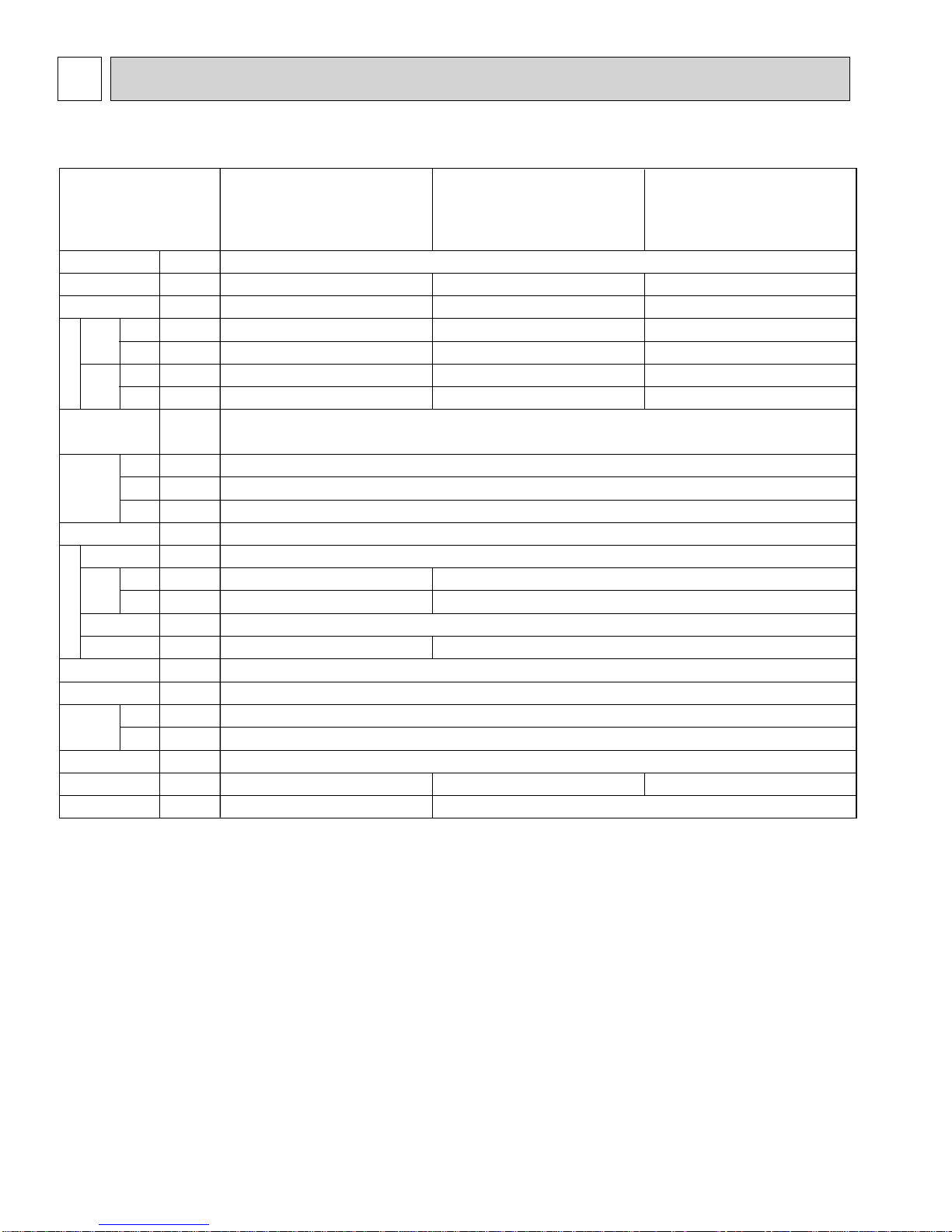
SPECIFICATIONS
4-1. SPECIFICATIONS
Item
Power
Cooling capacity
Heating capacity
Cooling
Input
Heating
Cooling
Current
Electric characteristic
(munsell symbol)
Dimensions
Heat exchanger
F a n
Pipe
dimensions
Field drain pipe size
Noise level 3
Product weight
Heating
Exterior
Height
Width
Depth
Fan × No.
Air flow
DRY
3
WET
External
static pressure
Fan motor
output
Insulator
Air filter
Gas
side
Liquid
side
V·Hz
Btu/h
Btu/h
kW
kW
A
A
—
in
in
in
—
—
CFM
CFM
Pa
kW
—
—
in
in
in
dB
lb
PLFY-P08NCMU-E.TH
PLFY-P08NCMU-E
1.TH
PLFY-P08NCMU-ER2.TH
PLFY-P08NCMU-ER3.TH
PLFY-P08NCMU-ER4.TH
8,000
9,000
0.05
0.05
0.23
0.23
Unit : Galvanized sheets with gray heat insulation
Grilles : ABS resin Munsell<0.7Y 8.59/0.97>(PLFY-P·NCMU-E.TH) / <6.4Y 8.9/0.4>(PLFY-P·NCMU-E1/ER2/ER3/ER4.TH)
280-320-350
250-290-320
0.015
29-32-38
34<7>
PLFY-P12NCMU-E.TH
PLFY-P12NCMU-E
PLFY-P12NCMU-ER2.TH
PLFY-P12NCMU-ER3.TH
PLFY-P12NCMU-ER4.TH
Single phase 208/230V 60Hz
Note 1. Rating conditions
Cooling : Indoor : D.B. 80°F W.B. 67°F
outdoor : D.B. 95°F W.B. 75°F
Heating : Indoor : D.B. 70°F
outdoor : D.B. 47°F W.B. 43°F
Note 2. The number indicated in < > is for the grille.
W 3. Air flow and the noise level are indicated as Low - Medium - High.
12,000
13,500
0.06
0.06
0.28
0.28
8-3/16<25/32>
22-7/16<25-19/32>
22-7/16<25-19/32>
Cross fin
Turbo fan × 1
0
Polyethylene sheet
PP honey comb fabric
1/2"
1/4"
O.D1-1/4"
30-34-39
1.TH
320-350-390
290-320-350
PLFY-P15NCMU-E.TH
PLFY-P15NCMU-E1.TH
PLFY-P15NCMU-ER2.TH
PLFY-P15NCMU-ER3.TH
PLFY-P15NCMU-ER4.TH
15,000
17,000
0.06
0.06
0.28
0.28
0.020
31-35-40
37<7>
6
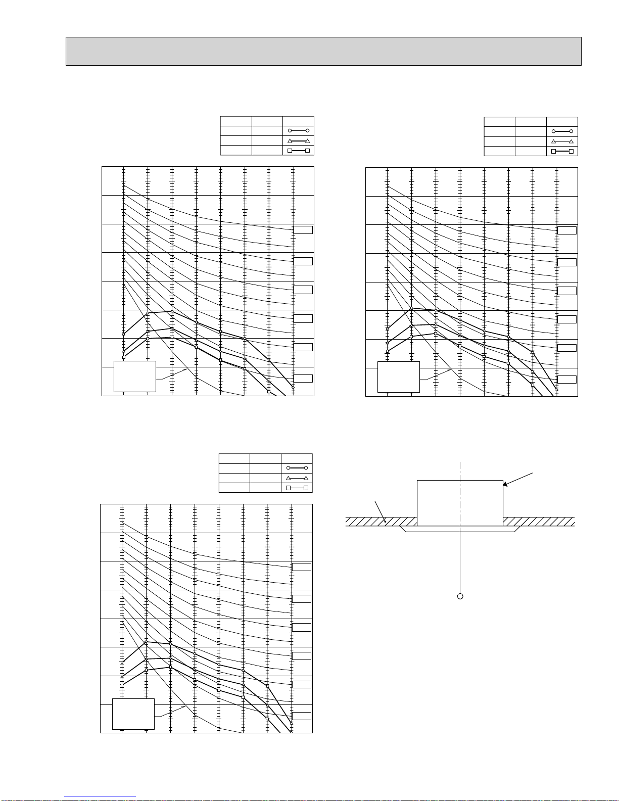
4-2. NOISE CRITERION CURVES
OCH410D
PLFY-P08NCMU-E.TH
PLFY-P08NCMU-E
1.TH
PLFY-P08NCMU-ER2.TH
PLFY-P08NCMU-ER3.TH
PLFY-P08NCMU-ER4.TH
90
80
70
60
50
40
30
APPROXIMATE
20
THRESHOLD OF
OCTAVE BAND SOUND PRESSURE LEVEL, dB (0 dB = 0.0002 μbar)
HEARING FOR
CONTINUOUS
NOISE
10
63 125 250 500 1000 2000 4000 8000
BAND CENTER FREQUENCIES, Hz
NOTCH
High
Medium
Low
SPL(dB)32LINE
38
29
NC-70
NC-60
NC-50
NC-40
NC-30
NC-20
PLFY-P12NCMU-E.TH
PLFY-P12NCMU-E
1.TH
PLFY-P12NCMU-ER2.TH
PLFY-P12NCMU-ER3.TH
PLFY-P12NCMU-ER4.TH
90
80
70
60
50
40
30
APPROXIMATE
20
THRESHOLD OF
OCTAVE BAND SOUND PRESSURE LEVEL, dB (0 dB = 0.0002 μbar)
HEARING FOR
CONTINUOUS
NOISE
10
63 125 250 500 1000 2000 4000 8000
BAND CENTER FREQUENCIES, Hz
NOTCH
High
Medium
Low
SPL(dB)34LINE
39
30
NC-70
NC-60
NC-50
NC-40
NC-30
NC-20
PLFY-P15NCMU-E.TH
PLFY-P15NCMU-E
1.TH
PLFY-P15NCMU-ER2.TH
PLFY-P15NCMU-ER3.TH
PLFY-P15NCMU-ER4.TH
90
80
70
60
50
40
30
APPROXIMATE
20
THRESHOLD OF
OCTAVE BAND SOUND PRESSURE LEVEL, dB (0 dB = 0.0002 μbar)
HEARING FOR
CONTINUOUS
NOISE
10
63 125 250 500 1000 2000 4000 8000
BAND CENTER FREQUENCIES, Hz
NOTCH
High
Medium
Low
SPL(dB)35LINE
40
31
NC-70
NC-60
NC-50
NC-40
NC-30
NC-20
UNIT
CEILING
5ft
MICROPHONE
NOTE: The sound level is measured in an anechoic
room where echoes are few, when compressor stops. The sound may be bigger than the
indicated level in actual use due to surrounding echoes. The sound level can be higher by
about 2 dB than the indicated level during cooling and heating operation.
7
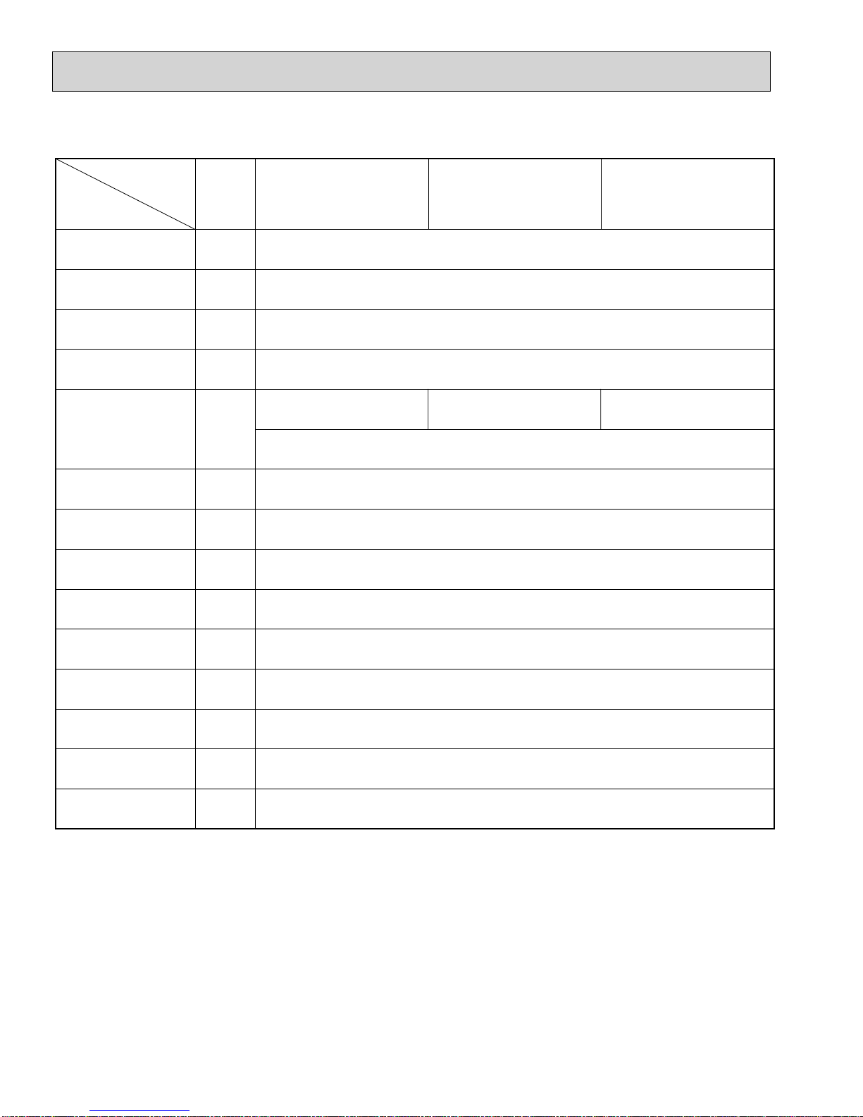
4-3. ELECTRICAL PARTS SPECIFICATIONS
OCH410D
Service ref.
Parts name
Thermistor
(Room temperature
detection)
Thermistor
(Pipe temperature
detection/ Liquid)
Thermistor
(Pipe temperature
detection/ Gas)
Fuse
(Indoor controller board)
Fan motor
(with Thermal fuse)
Fan motor capacitor
Vane motor
Drain pump
Symbol
TH21
TH22
TH23
FUSE
MF
C1
MV
DP
PLFY-P08NCMU-E.TH
PLFY-P08NCMU-E
PLFY-P08NCMU-ER2.TH
PLFY-P08NCMU-ER3.TH
PLFY-P08NCMU-ER4.TH
Resistance 30F/15.8k, 50F/9.6k, 70F/6.0k, 80F/4.8k, 90F/3.9k, 100F/3.2k
Resistance 30F/15.8k, 50F/9.6k, 70F/6.0k, 80F/4.8k, 90F/3.9k, 100F/3.2k
Resistance 30F/15.8k, 50F/9.6k, 70F/6.0k, 80F/4.8k, 90F/3.9k, 100F/3.2k
6-pole OUTPUT 15W
PK6N15-LA
1.TH
PLFY-P12NCMU-E.TH
PLFY-P12NCMU-E1.TH
PLFY-P12NCMU-ER2.TH
PLFY-P12NCMU-ER3.TH
PLFY-P12NCMU-ER4.TH
250V 6.3A
6-pole OUTPUT 20W
PK6N20-LA
Thermal fuse OFF 284F $ 36F
1.5 × 440V
MSBPC20M13
DC12V 300
PLD-12230ME-1
INPUT 12/10.8W 241/Hr
/phase
PLFY-P15NCMU-E.TH
PLFY-P15NCMU-E1.TH
PLFY-P15NCMU-ER2.TH
PLFY-P15NCMU-ER3.TH
PLFY-P15NCMU-ER4.TH
6-pole OUTPUT 20W
PK6N21-LA
Drain sensor
Linear expansion valve
[coil]
Electric heater
(Condensation proof)
Power supply terminal
block
Transmission terminal
block
MA remote controller
terminal block
+Note: Refer to WIRING DIAGRAM for the supplied voltage.
DS
LEV
H2
TB2
TB5
TB15
Thermistor resistance 30F/6.3k, 50F/3.9k, 70F/2.5k, 80F/2.0k, 90F/1.6k, 100F/1.3k
DC12V Stepping motor drive, Port dimension :3.2 (0~2000pulse)
EDM-40YGME
240V 15W
(L1, L2,GR) Rated to 330V 30A +
(M1, M2, S) Rated to 250V 20A +
(1, 2) Rated to 250V 10A +
8
5
OCH410D
4-WAY AIR FLOW SYSTEM
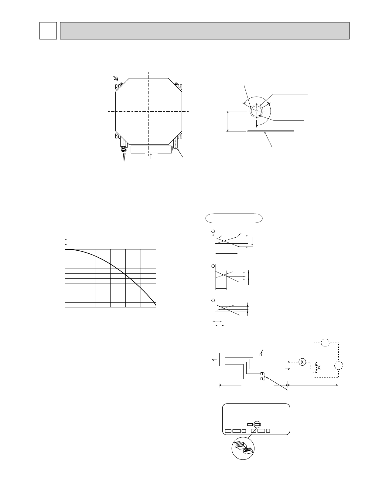
5-1. FRESH AIR INTAKE (Location for installation)
At the time of installation, use the duct holes (cut out) located at the positions shown in following diagram, as and when required.
Fresh air intake
Fresh air intake hole diagram (Unit : inch)
3 - W1/8
Burring hole
4-21/32
120"
W3-15/16
Burring hole pitch
120"
W2-7/8
(Cut out hole)
Ceiling surface
Refrigerant pipe
Electrical Box
Drain pipe
5-2. FRESH AIR INTAKE AMOUNT & STATIC PRESSURE CHARACTERISTICS
PLFY-P08/12/15NCMU-E.TH PLFY-P08/12/15NCMU-E1.TH
PLFY-P08/12/15NCMU-ER2.TH PLFY-P08/12/15NCMU-ER3.TH
PLFY-P08/12/15NCMU-ER4.TH
Taking air into the unit
Static pressure : P [in. W.G.%10-2]
20
20 40 60 80 100 120
0
-20
-40
-60
-80
-100
-120
NOTE: Fresh air intake amount should be 20% or less of
whole air amount to prevent dew dripping.
Air flow : Q [CFM]
How to read curves
Q
Duct characteristics
at site
A
C
B
A
EC
AD
Curve in the
1
left graphs
0
2
3
Q
Qa
Q
Q…Designed amount of fresh air intake
<CFM>
A…Static pressure loss of fresh air
intake duct system with air flow
amount Q <in. W.G.o10
B…Forced static pressure at air condi-
tioner inlet with air flow amount Q
<in. W.G.o10
C…Static pressure of booster fan with
air flow amount Q <in. W.G.o10
D…Static pressure loss increase
amount of fresh air intake duct sys-
tem for air flow amount Q
<in. W.G.o10-2>
E…Static pressure of indoor unit with
air flow amount Q <in. W.G.o10
Qa…Estimated amount of fresh air
intake without D <CFM>
-2
>
-2
>
-2
>
-2
>
5-3.
OPERATION IN CONJUNCTION
WITH DUCT FAN (BOOSTER FAN)
• Whenever the indoor unit is operating, the duct fun
also operates.
(1) Connect the optional multiple remote controller
adapter (PAC-SA88HA-E) to the connector
CN51 on the indoor controller board.
(2) Drive the relay after connecting the 12V
DC relay between the Yellow and Orange
connector wires.
(*) Use a relay of 1W or smaller.
MB: Electromagnetic switch power relay for duct fan.
X: Auxiliary relay (For DC 12V, coil rating : 1.0W or
below)
CN51
on
indoor unit
board
Indoor unit side
Indoor controller board
Multiple remote
controller adapter
PAC-SA88HA-E
9
5
1
Connector (5P)
CN51
Be sure to secure insulation
Green
material by tape, etc.
Red
Brown
Multiple remote
controller adapter
PAC-SA88HA-E
CN51
Yellow
Orange
~
MB
Installation at site
Be sure to secure insulation
material by tape, etc.
Distance between indoor
controller board and relay
must be within 33ft.
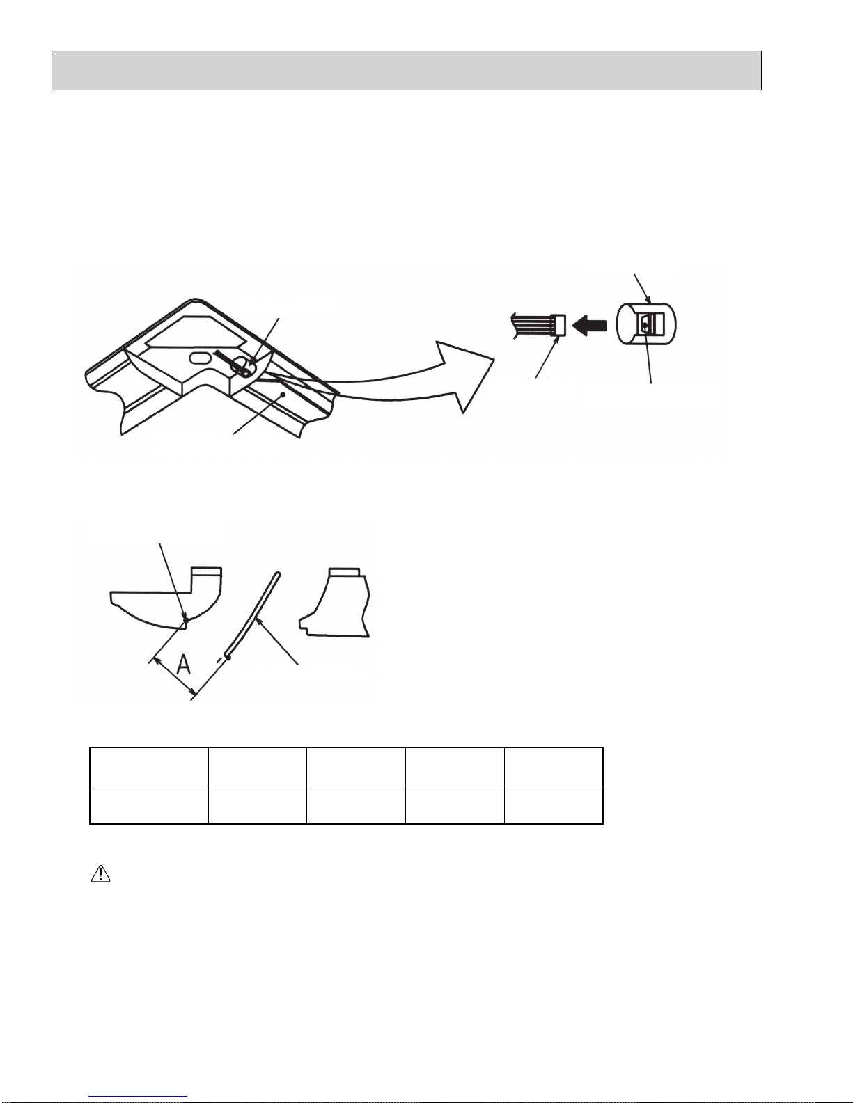
5-4. FIXING HORIZONTAL VANE
OCH410D
Horizontal vane of each air outlet can be fixed according to the environment where it is installed.
Setting procedure
1) Turn off a main power supply (Turn off a breaker).
2) Disconnect the vane motor connector of the direction of the arrow with pressing the unlocking button as shown in figure
below.
Insulate the disconnected connector with the plastic tape.
Vane motor
Vane motor
Connector
Unlocking button
Horizontal vane
3) Set a vertical vane of the air outlet, which is to be fixed by the hand slowly within the range in the table below.
Measured standard
position of the grille
Horizontal vane
< Specified range >
Up/down airflow
direction
A
· The vanes can be set between 21mm, 13/16 inch and 30 mm, 1-3/16 inch.
Horizontal 30° Downward 45° Downward 55° Downward 70°
21 mm
13/16 inch
25 mm
31/32 inch
28 mm
1-3/32 inch
30 mm
1-3/16 inch
Caution:
Do not set the up/down vanes passed the specified range. Condensation could form and drop from the ceiling,
or the unit could malfunction.
10
6
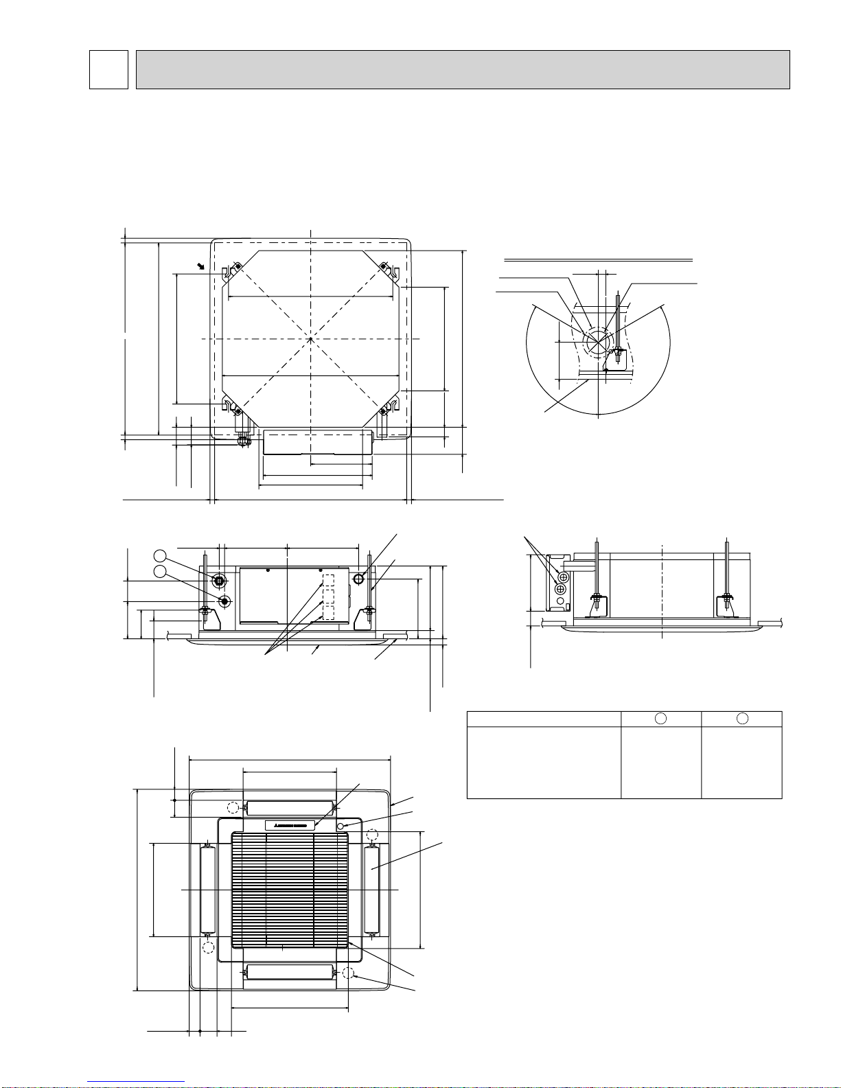
OCH410D
OUTLINES AND DIMENSIONS
PLFY-P08NCMU-E.TH PLFY-P12NCMU-E.TH PLFY-P15NCMU-E.TH
PLFY-P08NCMU-E
1.TH PLFY-P12NCMU-E1.TH PLFY-P15NCMU-E1.TH
PLFY-P08NCMU-ER2.TH PLFY-P12NCMU-ER2.TH PLFY-P15NCMU-ER2.TH
PLFY-P08NCMU-ER3.TH PLFY-P12NCMU-ER3.TH PLFY-P15NCMU-ER3.TH
PLFY-P08NCMU-ER4.TH PLFY-P12NCMU-ER4.TH PLFY-P15NCMU-ER4.TH
Unit : inch(mm)
Fresh air
intake
Ceiling hole
19/32~1-15/32(15~37)
16-17/32(420)
Suspension bolt pitch
20-7/8(530)
Suspension bolt pitch
22-7/16(570)
22-7/16(570)
13-3/16(335)
Detail drawing of fresh air intake
4-21/32(118)
1(25)
:2-7/8(:73.4)
Cut out hole
120
:3-15/16(:100)
3-:1/8(:2.8)
Burring hole
120
19/32~1-15/32(15~37)
22-11/16~24-13/32(576~620)
7-27/32(199)
2-1/4(57)
19/32~1-15/32(15~37) 19/32~1-15/32(15~37)
2-19/32(66)
3-21/32(93)
4-3/4(121)
2-7/32(56)
21/32(17)
2
1
1-1/2~2-9/32(38~58)
7-15/16(202)
Terminal block
13-27/32(352)
22-11/16~24-13/32(576~620)
13-3/16(335)
9-1/16(230)
Grille
Ceiling hole
Ceiling surface
Drain pipe
VP-25 connection
(O.D.:1-1/4(:32))
Suspension bolt M10 or W3/8
1-7/32(31)
8-3/16(208)
9-1/4(235)
7-19/32(193)
0
+5
(27 )
25/32(20)
0
+3/16
1-1/16
Suspension bolt lower edge
25-19/32(650)
1-3/8(35)
V/M
11-27/32(301)
Air outlet hole
Brand label
Grille
Drain hole
Ceiling surface
3-7/16(87)
Wiring entry
7-5/32(182)1-7/8(48)
Models
PLFY-P08/12/15NCMU-E.TH
PLFY-P08/12/15NCMU-E
PLFY-P08/12/15NCMU-ER2.TH
PLFY-P08/12/15NCMU-ER3.TH
PLFY-P08/12/15NCMU-ER4.TH
1.TH
1
Refrigerant pipe
(1/4 (6.35) dia.)
flared connection
Unit : inch(mm)
2
Refrigerant pipe
(1/2 (12.7) dia.)
flared connection
2-5/32(55)
11-27/32(301)
25-19/32(650)
Air outlet hole
V/M
14-27/32(377)
Air intake hole
1-3/8(35)
2-5/32(55)
V/M
V/M
Auto vane
14-27/32(377)
Air intake hole
Air intake grille
Vane motor
11
 Loading...