

Mitsubishi PLFY-P12NBMU-E, PLFY-P15NBMU-E, PLFY-P24NBMU-E, PLFY-P30NBMU-E, PLFY-P36NBMU-E Service Manual
...
SPLIT-TYPE, HEAT PUMP AIR CONDITIONERS
TECHNICAL & SERVICE MANUAL
R410A / R22
Indoor unit
[Model names] [Service Ref.]
PLFY-P12NBMU-E
PLFY-P15NBMU-E
PLFY-P18NBMU-E
PLFY-P24NBMU-E
PLFY-P30NBMU-E
PLFY-P36NBMU-E
PLFY-P12NBMU-E PLFY-P12NBMU-ER1
PLFY-P12NBMU-ER2
PLFY-P15NBMU-E PLFY-P15NBMU-ER1
PLFY-P15NBMU-ER2
PLFY-P18NBMU-E PLFY-P18NBMU-ER1
PLFY-P18NBMU-ER2
PLFY-P24NBMU-E PLFY-P24NBMU-ER1
PLFY-P24NBMU-ER2
PLFY-P30NBMU-E PLFY-P30NBMU-ER1
PLFY-P30NBMU-ER2
PLFY-P36NBMU-E PLFY-P36NBMU-ER1
PLFY-P36NBMU-ER2
April 2012
No. OCH421
REVISED EDITION-B
Revision:
• PLFY-P12/15/18/24/30/36
NBMU-ER2 have been
added in REVISED
EDITION-B.
• Some descriptions have
been modified.
• Please void OCH421
REVISED EDNTION-A.
Note:
•
This manual does not
cover outdoor units.
When servicing them,
please refer to the outdoor
unit’s service manual.
• RoHS compliant products
have <G> mark on the
spec name plate.
Model name
indication
INDOOR UNIT
CONTENTS
1. TECHNICAL CHANGES
2. FEATURES
3. PART NAMES AND FUNCTIONS
4. SPECIFICATIONS
5. 4-WAY AIR FLOW SYSTEM
6. OUTLINES AND DIMENSIONS
7. WIRING DIAGRAM
REFRIGERANT SYSTEM DIAGRAM
8.
9. MICROPROCESSOR CONTROL
10. TROUBLESHOOTING
11. DISASSEMBLY PROCEDURE
.............................................
.........................
...................................
.................
...............................
.........................
PARTS CATALOG (OCB421)
..........
............
......
.........
.............
2
3
4
6
10
13
14
16
17
24
33
Use the specifi ed refrigerant only
OCH421B
Never use any refrigerant other than that specifi ed.
Doing so may cause a burst, an explosion, or fi re when the unit is being used, serviced, or disposed of.
Correct refrigerant is specifi ed in the manuals and on the spec labels provided with our products.
We will not be held responsible for mechanical failure, system malfunction, unit breakdown or accidents caused
by failure to follow the instructions.
1
PLFY-P12NBMU-ER1 PLFY-P12NBMU-ER2
PLFY-P15NBMU-ER1 PLFY-P15NBMU-ER2
PLFY-P18NBMU-ER1 PLFY-P18NBMU-ER2
PKFY-P24NBMU-ER1 PLFY-P24NBMU-ER2
PKFY-P30NBMU-ER1 PLFY-P30NBMU-ER2
PKFY-P36NBMU-ER1 PLFY-P36NBMU-ER2
INDOOR CONTROLLER BOARD (I.B.) has been changed (S/W version up).
PLFY-P12NBMU-E PLFY-P12NBMU-ER1
PLFY-P15NBMU-E PLFY-P15NBMU-ER1
PLFY-P18NBMU-E PLFY-P18NBMU-ER1
PKFY-P24NBMU-E PLFY-P24NBMU-ER1
PKFY-P30NBMU-E PLFY-P30NBMU-ER1
PKFY-P36NBMU-E PLFY-P36NBMU-ER1
INDOOR CONTROLLER BOARD (I.B.) has been changed.
TECHNICAL CHANGES
2
2
OCH421B
FEATURES
Models
Cooling capacity / Heating capacity
PLFY-P12NBMU-E 12,000 / 13,500 Btu/h
PLFY-P15NBMU-E 15,000 / 17,000 Btu/h
PLFY-P18NBMU-E 18,000 / 20,000 Btu/h
PLFY-P24NBMU-E 24,000 / 27,000 Btu/h
PLFY-P30NBMU-E 30,000 / 34,000 Btu/h
PLFY-P36NBMU-E 36,000 / 40,000 Btu/h
Indoor Unit
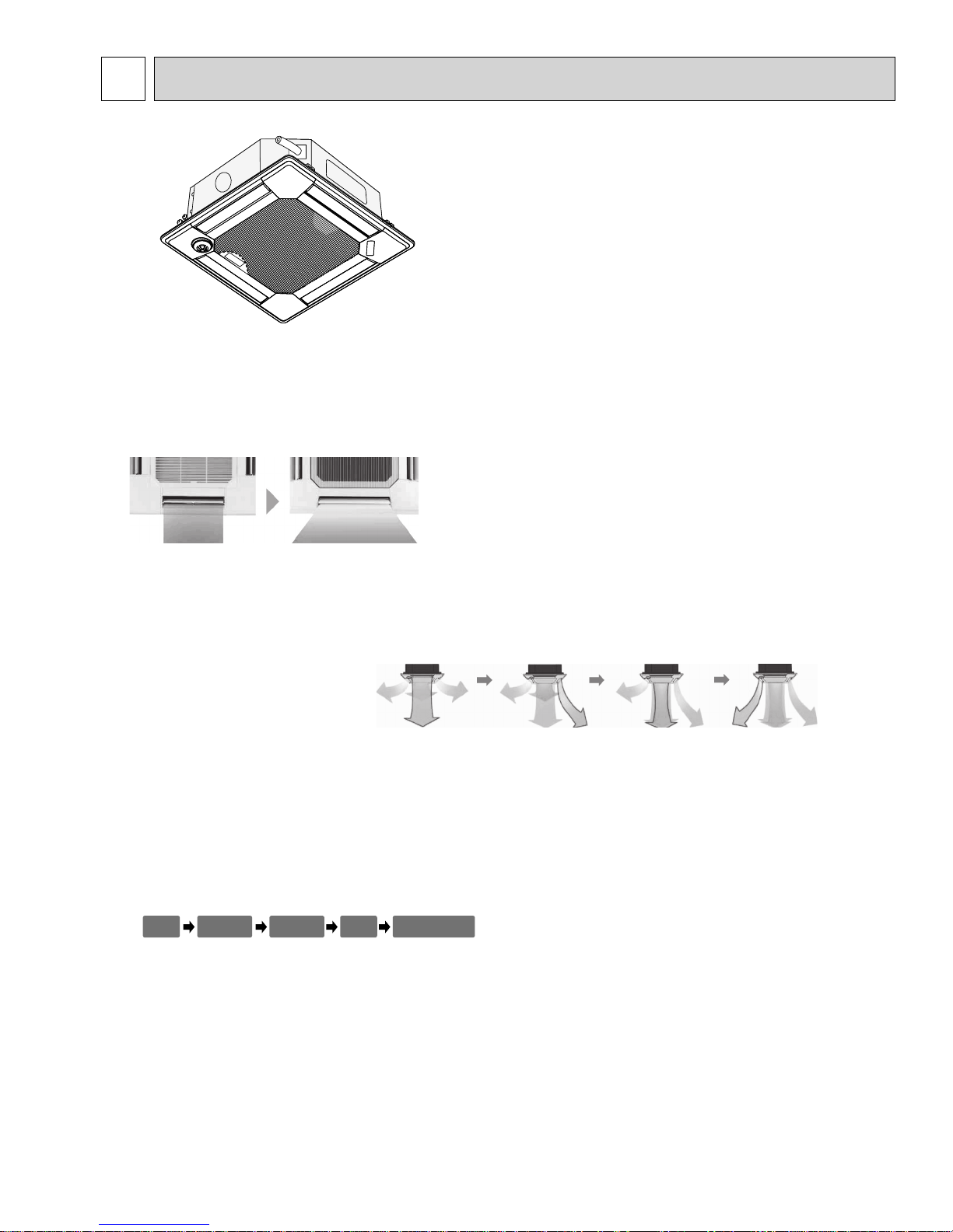
1. WIDE AIRFLOW
The new wide shape vane capable of wide angle air supply provides comfort even at the corners of a room regardless
of cooling and heating operation. A reduction in the air speed by 20% compared to the conventional product eliminates
uncomfortable draft sensation for friendly air conditioning.
2. WAVE AIRFLOW SYSTEM (HEATING MODE)
The wave airflow system has 4 vanes where each vane runs independently. Repeating of horizontal and down blows with a
time lag allows the conditioned warm air to be distributed even to room corners thus preventing uneven room temperature
distribution.
Operation image of "Wave Airflow"
3. AUTOMATIC AIR SPEED ADJUSTMENT MODE
The automatic air speed adjustment mode is provided in addition to the 4 air speed stages of "High/Medium 1/Medium 2/
Low." Air speed can be changed freely in accordance with a difference between the set temperature and the room temperature. The automatic air speed adjustment mode presents quick cooling of a room with the high mode, such as at the starting up of cooling operation, for example. After the room temperature is stabilized, the low mode will be applied by automatic
switching to keep your comfort.
Medium 2
Medium 1
HighLow
Automatic air
speed adjustment
4. i-see Sensor (OPTIONAL CORNER PANEL)
The i see sensor is a radiation temperature sensor originated from Mitsubishi’s new technology. In order to create a really
comfortable space in shops and offices, it is essential to control the temperature near the floor where occupants/visitors
gather. The i see sensor measures the infrared rays generated from the surrounding wall and floor surface at an angle of
360° and the infrared ray energy is computed to convert it into the value of temperature. In addition, the floor temperature
at distant spots (radiation temperature) is also measured to supply the optimum airflow to realize comfort which was never
experienced in the past.
3
3
OCH421B
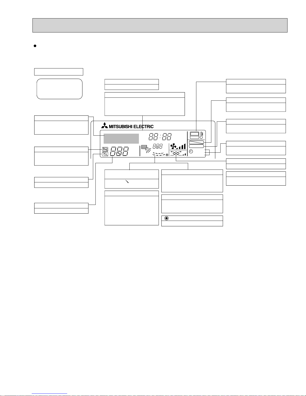
PART NAMES AND FUNCTIONS
Indoor unit
Air outlet
Liquid pipe
Gas pipe
i-see sensor
(option)
Vane
Wired remote controller
Drain pipe
Filter
Air intake
(Intake grille)
Note:
The phrase "Wired remote controller" in this manual refers only to the PAR-21MAA.
If you need any information for the other remote controller, please refer to either the installation manual or initial setting manual which are included in
remote controller's box.
Operation Section
Temperature setting buttons
Down
Up
Timer Menu button
(Monitor/Set button)
Mode button (Return button)
Set Time buttons
Back
Ahead
Timer On/Off button
(Set Day button)
Opening the
cover
TEMP.
MENU
MONITOR/SET
BACK DAY
PAR-21MAA
CLOCK
ON/OFF
ON/OFF
FILTER
CHECK
OPERATION
Built-in temperature sensor
CLEAR
TEST
ON/OFF button
Fan Speed button
Filter button
(<Enter> button)
Test Run button
Check button (Clear button)
Airflow Up/Down button
Louver button
( Operation button)
T o return operation
number
Ventilation button
( Operation button)
To go to next operation
number
4
Wired remote controller
OCH421B
Display Section
For purposes of this explanation,
all parts of the display are shown
as lit. During actual operation, only
the relevant items will be lit.
Identifies the current operation
Shows the operating mode, etc.
*Multilanguage display is available.
“Centrally Controlled” indicator
Indicates that operation from the
remote controller has been prohibited by a master controller.
“Timer is Off” indicator
Indicates that the timer is off.
Temperature Setting
Shows the target temperature.
Day-of-Week
Shows the current day of the week.
Time/Timer Display
Shows the current time, unless the simple or Auto Off
timer is set.
If the simple or Auto Off timer is set, the time to be
switched off is shown.
TIME SUN MON TUE WED THU FRI SAT
TIMER
AFTER
ERROR CODE
°F°C
Hr
AFTER
°F°C
ONLY1Hr.
Up/Down Air Direction indicator
The indicator shows the direction of the outcoming airflow.
“One Hour Only” indicator
Displayed if the airflow is set to
Low or downward during COOL
or DRY mode. (Operation varies
according to model.)
The indicator goes off in one hour,
at which time the airflow direction
also changes.
Room Temperature display
Shows the room temperature. The room
temperature display range is 46–102F.
The display blinks if the temperature
is less than 46
Louver display
Indicates the action of the swing louver.
Does not appear if the louver is not
running.
(Power On indicator)
Indicates that the power is on.
ON
OFF
FUNCTION
FILTER
WEEKLY
SIMPLE
AUTO OFF
F
or 102F or more.
“Sensor” indication
Displayed when the remote controller
sensor is used.
“Locked” indicator
Indicates that remote controller buttons have been locked.
“Clean The Filter” indicator
To be displayed on when it is time to
clean the filter.
Timer indicators
The indicator comes on if the corresponding timer is set.
Fan Speed indicator
Shows the selected fan speed.
Ventilation indicator
Appears when the unit is running in
Ventilation mode.
5
4
OCH421B
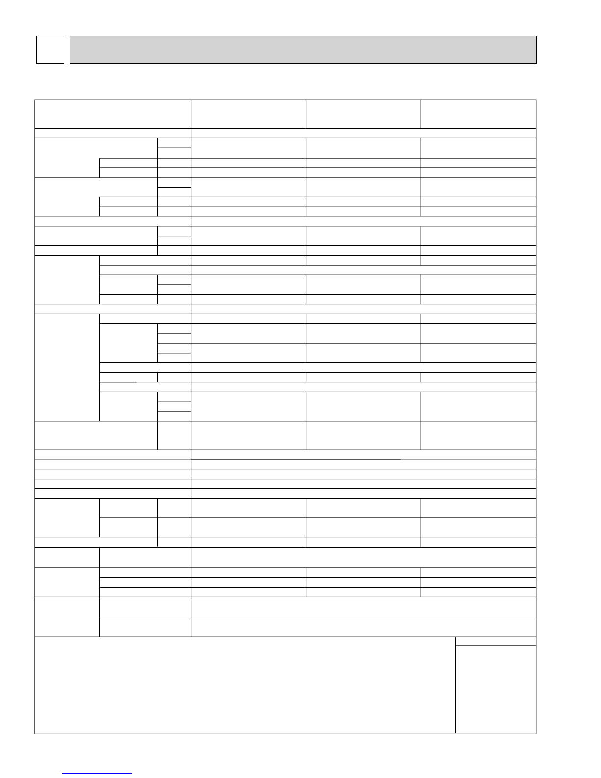
SPECIFICATIONS
4-1. SPECIFICATIONS
Model
Power source
Cooling capacity
(Nominal)
Heating capacity
(Nominal )
External finish
External dimension H
Net weight
Decoration panel
Heat exchanger
FAN
Noise level (Low-Mid2-Mid1-High)
(measured in anechoic room)
Insulation material
Air filter
Protection device
Refrigerant control device
Connectable outdoor unit
Diameter of
refrigerant pipe
(O.D.)
Field drain pipe size
Standard
attachment
Optional parts
Remark
Power input
Current input
Power input
Current input
×
W × D
Model
External finish
Dimension
H
×
W × D
Net weight
Type x Quantity
External
static press.
Motor type
Motor output
Driving mechanism
Airflow rate
(Low-Mid2-
Mid1-High)
Liquid
Gas
Document
Accessory
Air outlet shutter plate
High efficiency filterelement
Multi-function casement
*1
*1
*2
*2
(R410A)
(R22)
(R410A)
(R22)
BTU/h
kW
kW
A
Btu/h
kcal/h
kW
A
in.
mm
Ibs (kg)
in.
mm
Ibs (kg)
in.WG
Pa
in.WG
Pa
kW
cfm
m3/min
L / s
dB <A>
dB <A>
dB <A>
in. (mm)
in. (mm)
in. (mm)
PLFY-P12NBMU-E
PLFY-P12NBMU-ER1
PLFY-P12NBMU-ER2
12,000
3.5
0.03
0.22
13,500
4.0
0.02
0.14
10-3/16 × 33-3/32 × 33-3/32 10-3/16 × 33-3/32 × 33-3/32 10-3/16 × 33-3/32 × 33-3/32
258
×
840 × 840
49 (22) 49 (22) 51 (23)
PLP-40BAU PLP-40BAU PLP-40BAU
1-3/8 × 37-13/32 × 37-13/32
×
950 × 950
35
13 (6) 13 (6) 13 (6)
0.000 (208V) 0.000 (208V) 0.000 (208V)
0
0.000 (230V)
0
0.050
388 - 424 - 459 - 494
11.0 - 12.0 - 13.0 - 14.0
183 - 200 - 217 - 233
27 - 28 - 29 - 31 (208-230V)
—
—
PP honeycomb (long life filter, anti-bacterial type)
1/4 (6.35) Flare
1/4 (6.35) Flare
1/2 (12.7) Flare
1/2 (12.7) Flare
O.D. 1-1/4 (32) O.D. 1-1/4 (32) O.D. 1-1/4 (32)
PAC-SH51SP-E
PAC-SH59KF-E
PAC-SH53TM-E
PLFY-P15NBMU-E
PLFY-P15NBMU-ER1
PLFY-P15NBMU-ER2
1-phase 208-230V 60Hz
15,000
4.4
0.04
0.29
17,000
5.0
0.03
0.22
Galvanized steel sheet
258× 840 × 840 258× 840 × 840
MUNSELL (6.4Y 8.9/0.4)
1-3/8 × 37-13/32 × 37-13/32
35× 950 × 950
Cross fin
Turbo fan
0.000 (230V)
424 - 459 - 494 - 565
12.0 - 13.0 - 14.0 - 16.0
200 - 217 - 233 - 267
27 - 28 - 30 - 31 (208-230V)
R410A, R22 CITY MULTI
1/4 (6.35) Flare
1/4 (6.35) Flare
1/2 (12.7) Flare
1/2 (12.7) Flare
Installation Manual, Instruction Book
PAC-SH51SP-E
PAC-SH59KF-E
PAC-SH53TM-E
0
0
DC motor
0.050
Direct-drive
—
—
PS
Fuse
LEV
×
1Turbo fan × 1 Turbo fan × 1
PLFY-P18NBMU-E
PLFY-P18NBMU-ER1
PLFY-P18NBMU-ER2
18,000
5.3
0.05
0.36
20,000
5.9
0.04
0.29
1-3/8 × 37-13/32 × 37-13/32
35× 950 × 950
0
0.000 (230V)
0
0.050
494 - 530 - 565 - 636
14.0 - 15.0 - 16.0 - 18.0
233 - 250 - 267 - 300
28 - 29 - 30- 32 (208-230V)
—
—
1/4 (6.35) Flare
3/8 (9.52) Flare
1/2 (12.7) Flare
5/8 (15.88) Flare
PAC-SH51SP-E
PAC-SH59KF-E
PAC-SH53TM-E
Installation
*1 Nominal cooling conditions Note: *2 Nominal heating conditions
Indoor : 80degF D.B. / 67degF W.B.
(26.7degC D.B. / 19.4degC W.B.)
Outdoor : 95degF D.B. 47degF D.B. / 43degF W.B.
Pipe length : 25 ft. (7.6 m) 25 ft. (7.6 m)
Level difference : 0 ft. (0 m) 0 ft. (0 m)
*Due to continuing improvement, above specification may be subject to change without notice.
(35degC D.B.) (8.3degC D.B. / 6.1degC W.B.)
Details on foundation work, duct work, insulation work, electrical wiring, power source switch, and other items
shall be referred to the Installation Manual.
70degF D.B.
(21.1degC D.B.)
Unit converter
kcal/h = kW × 860
BTU/h = kW × 3,412
3
cfm = m
/min × 35.31
lbs = kg/0.4536
*Above specification
data is subject to
rounding variation.
6
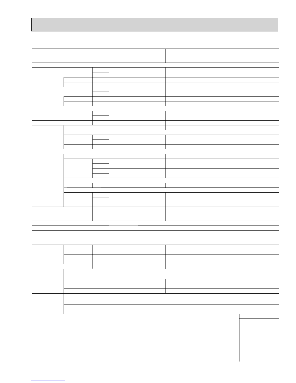
Model
OCH421B
Power source
Cooling capacity
(Nominal)
Heating capacity
(Nominal )
External finish
External dimension H × W × D
Net weight
Decoration panel
Heat exchanger
FAN
Noise level (Low-Mid2-Mid1-High)
(measured in anechoic room)
Insulation material
Air filter
Protection device
Refrigerant control device
Connectable outdoor unit
Diameter of
refrigerant pipe
(O.D.)
Field drain pipe size
Standard
attachment
Optional parts
Remark
Power input
Current input
Power input
Current input
Model
External finish
Dimension
H × W × D
Net weight
Type × Quantity
External
static press.
Motor type
Motor output
Driving mechanism
Airflow rate
(Low-Mid2-
Mid1-High)
Liquid
Gas
Document
Accessory
(R410A)
(R410A)
Air outlet shutter plate
High efficiency filterelement
Multi-function casement
(R22)
(R22)
*1
*1
*2
*2
BTU/h
kW
kW
A
Btu/h
kcal/h
kW
A
in.
mm
Ibs (kg)
in.
mm
Ibs (kg)
in.WG
Pa
in.WG
Pa
kW
cfm
3
m
/min
L/s
dB <A>
dB <A>
dB <A>
in. (mm)
in. (mm)
in. (mm)
PLFY-P24NBMU-E
PLFY-P24NBMU-ER1
PLFY-P24NBMU-ER2
24,000
7.0
0.06
0.43
27,000
7.9
0.05
0.36
10-3/16× 33-3/32 × 33-3/32
258 × 840 × 840
51 (23)
PLP-40BAU
1-3/8× 37-13/32 × 37-13/32
35 × 950 × 950
13 (6)
0.000 (208V)
0
0.000 (230V)
0
0.050
530 - 565 - 636 - 706
15.0 - 16.0 - 18.0 -20.0
250 - 267 - 300 - 333
28 - 30 - 32 - 34 (208-230V)
—
—
3/8 (9.52) Flare
3/8 (9.52) Flare
5/8 (15.88) Flare
5/8 (15.88) Flare
O.D. 1-1/4 (32)
PAC-SH51SP-E
PAC-SH59KF-E
PAC-SH53TM-E
PLFY-P30NBMU-E
PLFY-P30NBMU-ER1
PLFY-P30NBMU-ER2
1-phase 208-230V 60Hz
30,000
8.8
0.07
0.51
34,000
10.0
0.06
0.43
Galvanized steel sheet
10-3/16× 33-3/32 × 33-3/32
258 × 840 × 840
51 (23)
PLP-40BAU
MUNSELL (6.4Y 8.9/0.4)
1-3/8× 37-13/32 × 37-13/32
35 × 950 × 950
13 (6)
Cross fin
0.000 (208V)
0
0.000 (230V)
0
DC motor
0.050
Direct-drive
565 - 636 - 706 - 777
16.0 - 18.0 - 20.0 - 22.0
267 - 300 - 333 - 367
30 - 32 - 35 - 37 (208-230V)
PP honeycomb (long life filter, anti-bacterial type)
R410A, R22 CITY MULTI
Installation Manual, Instruction Book
—
—
PS
Fuse
LEV
3/8 (9.52) Flare
3/8 (9.52) Flare
5/8 (15.88) Flare
5/8 (15.88) Flare
O.D. 1-1/4 (32)
PAC-SH51SP-E
PAC-SH59KF-E
PAC-SH53TM-E
PLFY-P36NBMU-E
PLFY-P36NBMU-ER1
PLFY-P36NBMU-ER2
36,000
10.5
0.16
1.07
40,000
11.7
0.15
1.00
11-3/4 × 33-3/32 × 33-3/32
298 × 840 × 840
60 (27)
PLP-40BAU
1-3/8× 37-13/32 × 37-13/32
35 × 950 × 950
13 (6)
Turbo fan × 1 Turbo fan × 1 Turbo fan × 1
0.000 (208V)
0
0.000 (230V)
0
0.120
777 - 883 - 989 - 1,059
22.0 - 25.0 - 28.0 - 30.0
367 - 417 - 467 - 500
35 - 38 - 41 - 43 (208-230V)
—
—
3/8 (9.52) Flare
3/8 (9.52) Flare
5/8 (15.88) Flare
3/4 (19.05) Flare
O.D. 1-1/4 (32)
PAC-SH51SP-E
PAC-SH59KF-E
PAC-SH53TM-E
Installation
*1 Nominal cooling conditions Note: *2 Nominal heating conditions
Indoor : 80degF D.B. / 67degF W.B.
(26.7degC D.B. / 19.4degC W.B.)
Outdoor : 95degF D.B. 47degF D.B. / 43degF W.B.
Pipe length : 25 ft. (7.6 m) 25 ft. (7.6 m)
Level difference : 0 ft. (0 m) 0 ft. (0 m)
*Due to continuing improvement, above specification may be subject to change without notice.
(35degC D.B.) (8.3degC D.B. / 6.1degC W.B.)
Details on foundation work, duct work, insulation work, electrical wiring, power source switch, and other items
shall be referred to the Installation Manual.
70degF D.B.
(21.1degC D.B.)
Unit converter
kcal/h = kW × 860
BTU/h = kW × 3,412
3
/min × 35.31
cfm = m
lbs = kg/0.4536
*Above specification
data is subject to
rounding variation.
7
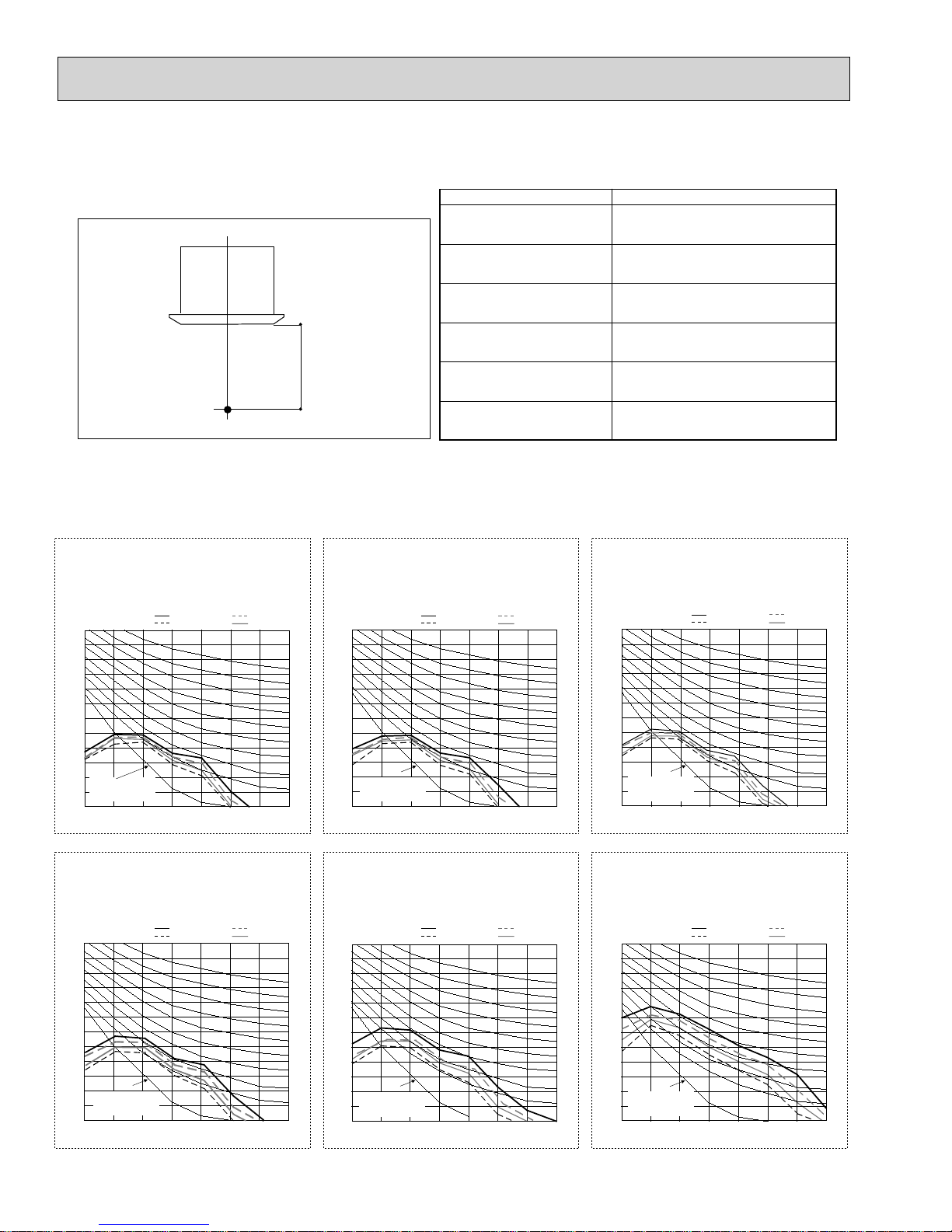
4-2. SOUND LEVEL
OCH421B
PLFY-P-NBMU-E
Measurement location
4-3. NC CURVES
PLFY-P12NBMU-E
PLFY-P12NBMU-ER1
PLFY-P12NBMU-ER2
External static pressure : 0Pa
Power source : 208,230V, 60Hz
70.0
65.0
60.0
55.0
50.0
45.0
40.0
35.0
30.0
25.0
20.0
Approximate minimum
audible limit on
15.0
continuous noise
Octave band pressure level (dB) 0dB=20Pa
10.0
63 125 250 500 1k 2k 4k 8k
Octave band center frequencies (Hz)
High 60Hz
Low 60Hz
Middle1 60Hz
Middle2 60Hz
5 ft (1.5m)
PLFY-P15NBMU-E
PLFY-P15NBMU-ER1
PLFY-P15NBMU-ER2
External static pressure : 0Pa
Power source : 208,230V, 60Hz
70.0
65.0
NC-60
NC-50
NC-40
NC-30
NC-20
60.0
55.0
50.0
45.0
40.0
35.0
30.0
25.0
20.0
Approximate minimum
audible limit on
15.0
continuous noise
Octave band pressure level (dB) 0dB=20Pa
10.0
63 125 250 500 1k 2k 4k 8k
Octave band center frequencies (Hz)
PLFY-P12NBMU-E
PLFY-P12NBMU-ER1
PLFY-P12NBMU-ER2
PLFY-P15NBMU-E
PLFY-P15NBMU-ER1
PLFY-P15NBMU-ER2
PLFY-P18NBMU-E
PLFY-P18NBMU-ER1
PLFY-P18NBMU-ER2
PLFY-P24NBMU-E
PLFY-P24NBMU-ER1
PLFY-P24NBMU-ER2
PLFY-P30NBMU-E
PLFY-P30NBMU-ER1
PLFY-P30NBMU-ER2
PLFY-P36NBMU-E
PLFY-P36NBMU-ER1
PLFY-P36NBMU-ER2
High 60Hz
Low 60Hz
Middle1 60Hz
Middle2 60Hz
Sound level at anechoic room : Low-
Sound level dB (A)
27-28-29-31
27-28-30-31
28-29-30-32
28-30-32-34
30-32-35-37
35-38-41-43
PLFY-P18NBMU-E
PLFY-P18NBMU-ER1
PLFY-P18NBMU-ER2
External static pressure : 0Pa
Power source : 208,230V, 60Hz
70.0
65.0
NC-60
NC-50
NC-40
NC-30
NC-20
60.0
55.0
50.0
45.0
40.0
35.0
30.0
25.0
20.0
Approximate minimum
audible limit on
15.0
continuous noise
Octave band pressure level (dB) 0dB=20Pa
10.0
63 125 250 500 1k 2k 4k 8k
Octave band center frequencies (Hz)
High 60Hz
Low 60Hz
Mid2-Mid1-High
Middle1 60Hz
Middle2 60Hz
NC-60
NC-50
NC-40
NC-30
NC-20
PLFY-P24NBMU-E
PLFY-P24NBMU-ER1
PLFY-P24NBMU-ER2
External static pressure : 0Pa
Power source : 208,230V, 60Hz Power source : 208,230V, 60Hz
70.0
65.0
60.0
55.0
50.0
45.0
40.0
35.0
30.0
25.0
20.0
Approximate minimum
audible limit on
15.0
continuous noise
Octave band pressure level (dB) 0dB=20Pa
10.0
63 125 250 500 1k 2k 4k 8k
Octave band center frequencies (Hz)
High 60Hz
Low 60Hz
Middle1 60Hz
Middle2 60Hz
NC-60
NC-50
NC-40
NC-30
NC-20
PLFY-P30NBMU-E
PLFY-P30NBMU-ER1
PLFY-P30NBMU-ER2
External static pressure : 0Pa
Power source : 208,230V, 60Hz
70.0
65.0
60.0
55.0
50.0
45.0
40.0
35.0
30.0
25.0
20.0
Approximate minimum
audible limit on
15.0
continuous noise
Octave band pressure level (dB) 0dB=20Pa
10.0
63 125 250 500 1k 2k 4k 8k
Octave band center frequencies (Hz)
High 60Hz
Low 60Hz
8
Middle1 60Hz
Middle2 60Hz
PLFY-P36NBMU-E
PLFY-P36NBMU-ER1
PLFY-P36NBMU-ER2
External static pressure : 0Pa
70.0
65.0
NC-60
NC-50
NC-40
NC-30
NC-20
60.0
55.0
50.0
45.0
40.0
35.0
30.0
25.0
20.0
Approximate minimum
audible limit on
15.0
continuous noise
Octave band pressure level (dB) 0dB=20Pa
10.0
63 125 250 500 1k 2k 4k 8k
Octave band center frequencies (Hz)
High 60Hz
Low 60Hz
Middle1 60Hz
Middle2 60Hz
NC-60
NC-50
NC-40
NC-30
NC-20
4-4. ELECTRICAL PARTS SPECIFICATIONS
OCH421B
Service Ref.
Parts name
Room temperature
thermistor
Liquid pipe thermistor
Gas pipe thermistor
Fuse
(Indoor controller board)
Fan motor
Vane motor
Drain pump
Drain float swich
Linear expansion valve
Power supply terminal
block
Transmission terminal
block
MA remote controller
terminal block
Symbol
TH21
TH22
TH23
FUSE
MF
MV
DP
FS
LEV
TB2
TB5
TB15
PLFY-P12NBMU-E
PLFY-P12NBMU-ER1
PLFY-P12NBMU-ER2
DC12V Stepping motor drive port dimension :3.2 (0~2000pulse)
PLFY-P15NBMU-E
PLFY-P15NBMU-ER1
PLFY-P15NBMU-ER2
Resistance 30"F/15.8k, 50"F/9.6k, 70"F/6.0k, 80"F/4.8k, 90"F/3.9k, 100"F/3.2k
Resistance 30"F/15.8k, 50"F/9.6k, 70"F/6.0k, 80"F/4.8k, 90"F/3.9k, 100"F/3.2k
Resistance 30"F/15.8k, 50"F/9.6k, 70"F/6.0k, 80"F/4.8k, 90"F/3.9k, 100"F/3.2k
PLFY-P18NBMU-E
PLFY-P18NBMU-ER1
PLFY-P18NBMU-ER2
8-pole OUTPUT 50W
EDM-40YGME
PLFY-P24NBMU-E
PLFY-P24NBMU-ER1
PLFY-P24NBMU-ER2
250V 6.3A
MSBPC20M04
DC12V 300
PLD-12230ME-1
INPUT 12/10.8W 241/Hr
Open/short detection
(L1, L2, GR) 330V 30A
(M1, M2, S) 250V 20A
(1, 2) 250V 10A
/phase
PLFY-P30NBMU-E
PLFY-P30NBMU-ER1
PLFY-P30NBMU-ER2
DC12V Stepping motor drive port
dimension :
PLFY-P36NBMU-E
PLFY-P36NBMU-ER1
PLFY-P36NBMU-ER2
8-pole OUTPUT,
5.2
(0~2000pulse)
EDM-80YGME
120W
9
5
OCH421B
4-WAY AIR FLOW SYSTEM
5-1. PLACEMENT OF THE AIR OUTLETS
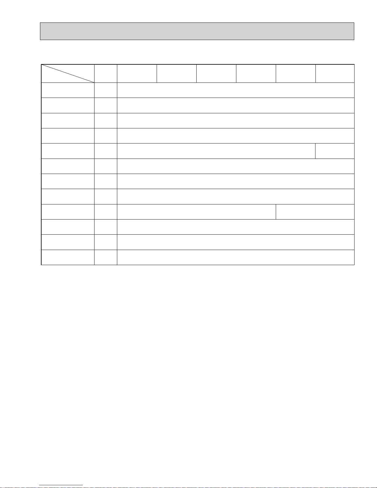
• For this grille, the blowout direction comes in 11 patterns.
Also, by setting the remote controller to the appropriate settings, you can adjust the air flow and speed. Select the settings
from Table1 according to the location in which you want to install the unit.
1) Decide on the pattern of the airflow direction.
4-direction<Table 1> 3-direction 2-direction
Pattern 1 Initial setting Pattern 4 One air outlet
fully closed
Pattern 6 2 air outlet
fully closed
pattern
Blowout direction
Note: For 3 and 2-direction settings, please use the air outlet shutter plate (option).
2) According to the number of air outlets and height of the ceiling to install the unit, be sure to set up the switches
(SWA, SWB) on the address board to the appropriate setting.
• Correspondence of ceiling heights to numbers of air outlets
SWB
SWA
2
3
3
ON
OFF
12345678910
SW12
0
1
9
2
8
3
7
4
6
5
(10ths DIGIT)
SW1
SW11
9
8
7
6
(1s DIGIT)
2
1
0
1
5
SWC
2
3
4
4
CN82
SW14
E
D
C
(BRANCH No.)
F
B
A
CN43
0
1
2
3
6
7
8
9
./
4
5
.
PLFY-P12·P15·P18·P24·P30NBMU-E
PLFY-P12·P15·P18·P24·P30NBMU-ER1
PLFY-P12·P15·P18·P24·P30NBMU-ER2
Silent
2.5m, 8.2ft
2.7m, 8.9ft
3.0m, 9.8ft
Standard
2.7m, 8.9ft
3.0m, 9.8ft
3.3m, 10.8ft
SWB
4 direction
3 direction
2 direction
SWA
PLFY-P36NBMU-E
PLFY-P36NBMU-ER1
PLFY-P36NBMU-ER2
SWA
SWB
4 direction
3 direction
2 direction
Silent
2.7m, 8.9ft
3.0m, 9.8ft
3.3m, 10.8ft
Standard
3.2m, 10.5ft
3.6m, 11.8ft
4.0m, 13.1ft
High ceiling
3.5m, 11.5ft
3.5m, 11.5ft
3.5m, 11.5ft
High ceiling
4.5m, 14.8ft
4.5m, 14.8ft
4.5m, 14.8ft
10
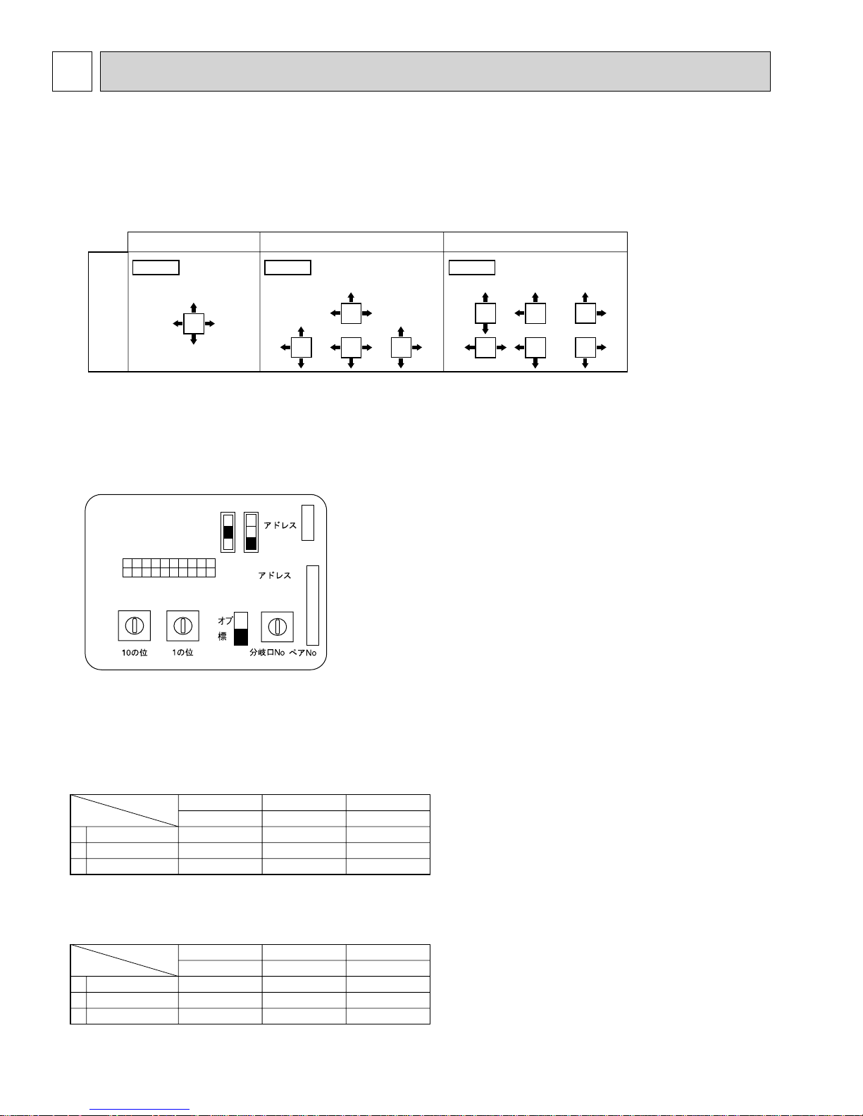
5-2. BRANCH DUCT HOLE AND FRESH AIR INTAKE HOLE
OCH421B
At the time of installation, use the duct holes (cut out) located at the positions shown in following diagram, as and when required.
• A fresh air intake hole for the optional multi function casement can also be made.
Note:
The figures marked with * in the drawing below represent the dimensions of the main unit excluding those of the optional multi
function casement.
When installing the optional multi function casement, add 5-5/16” (135 mm) to the dimensions marked on the figure.
When installing the branch ducts, be sure to insulate adequately.
Otherwise, condensation and dripping may occur.
Unit : inch(mm)
Fresh air intake hole
Refrigerant pipe
Indoor unit
Branch duct hole
Drain pipe
:6-7/8 (:175) burring hole pitch
Branch duct hole diagram
(view from either side)
Fresh air intake hole diagram
3-:1/8 (:2.8) burring hole
120
(*158)
6-7/32
3-17/32
3-15/16
3-15/16
(90)
3-17/32
(90)
70
(90)
(100)
13-25/32 (350)
:4-29/32 (:125) burring hole pitch
120
:3-15/16 (:100) cut out hole
Ceiling
3-15/16 (100)
5-1/8 (130)
*6-3/32 (155)
*6-9/16 (167)
14-:1/8 (:2.8) burring hole
:5-29/32 (:150) cut out hole
5-3. OPERATION IN CONJUNCTION WITH
DUCT FAN (Booster fan)
• Whenever the indoor unit is operating, the duct fan also
operates.
(1) Connect the optional multiple remote controller adapter
(PAC-SA88HA-E) to the connector CN51 on the indoor
controller board.
(2) Drive the relay after connecting the 12V DC relay
between the Yellow and Orange connector lines.
MB: Electromagnetic switch power relay for duct fan.
X: Auxiliary relay (For DC 12V, coil rating: 1.0W or smaller)
CN51
on
indoor
controller
board
Indoor controller board
Multiple remote
controller adapter
PAC-SA88HA-E
11
5
1
Connector (5P)
Indoor unit side
CN51
Be sure to secure insulation
Green
CN51
material by tape, etc.
Red
Brown
Multiple remote
controller adapter
PAC-SA88HA-E
Yellow
Orange
~
MB
Installation at site
Be sure to secure insulation
material by tape, etc.
Distance between indoor
controller board and relay
must be within 10m (33ft).
 Loading...