

Mitsubishi PLFY-P63VAM-E, PLFY-P80VAM-E, PLFY-P40VAM-E, PLFY-P50VAM-E, PLFY-P100VAM-E Technical & Service Manual
...
SPLIT-TYPE, HEAT PUMP AIR CONDITIONERS
TECHNICAL & SERVICE MANUAL
No. OC313
REVISED EDITION-A
Series PLFY
Indoor unit
[Model names] [Service Ref.]
PLFY-P32VAM-E PLFY-P32VAM-E.UK
PLFY-P40VAM-E PLFY-P40VAM-E.UK
PLFY-P50VAM-E PLFY-P50VAM-E.UK
PLFY-P63VAM-E PLFY-P63VAM-E.UK
PLFY-P80VAM-E PLFY-P80VAM-E.UK
PLFY-P100VAM-E PLFY-P100VAM-E.UK
PLFY-P125VAM-E PLFY-P125VAM-E.UK
Ceiling Cassettes
R410A
CONTENTS
1. SAFETY PRECAUTION··························2
2. PART NAMES AND FUNCTIONS··········6
3. SPECIFICATIONS···································8
4. 4-WAY AIR FLOW SYSTEM·················11
5. OUTLINES AND DIMENSIONS············14
6. WIRING DIAGRAM ·······························15
7.
REFRIGERANT SYSTEM DIAGRAM
8. TROUBLE SHOOTING ·························17
9. DISASSEMBLY PROCEDURE·············24
10. PARTS LIST··········································27
INDOOR UNIT
11. OPTIONAL PARTS ················Back cover
R407C
R22
·····16
Revision:
• “ 10. PARTS LIST ” has been modified.
•Please void OC313
Do not use the existing refrigerant piping.
The old refrigerant and lubricant in the existing piping
contains a large amount of chlorine which may cause the
lubricant deterioration of the new unit.
Use “low residual oil piping”
If there is a large amount of residual oil (hydraulic oil, etc.)
inside the piping and joints, deterioration of the lubricant
will result.
Use ESTR , ETHER or HAB as the lubricant to
coat flares and flange connection parts.
If large amount of mineral oil enter, that can cause
deterioration of refrigerant oil etc.
Use liquid refrigerant to charge the system.
If gas refrigerant is used to seal the system, the composition
of the refrigerant in the cylinder will change and performance
may drop.
Do not use a refrigerant other than R407C.
If another refrigerant (R22, etc.) is used, the chlorine in the
refrigerant may cause the lubricant deterioration.
Use a vacuum pump with a reverse flow check valve.
The vacuum pump oil may flow back into the refrigerant
cycle and cause the lubricant deterioration.
Store the piping to be used during installation
indoors with keep both ends sealed until just
before brazing.
(Store elbows and other joints in a plastic bag.)
If dust, dirt, or water enters the refrigerant cycle,
deterioration of the oil and compressor trouble may result.
Ventilate the room if refrigerant leaks during
operation. If refrigerant comes into contact with
a flame, poisonous gases will be released.
Revision:
Service Ref.
Page
30
31
IncorrectRevise point
10. PART LIST
FUNCTIONAL PARTS
No.7 POWER BOARD
10. PART LIST
FUNCTIONAL PARTS
No.1 DRAIN PAN
S70 E00 529
S70 E20 313
S70 E01 529
S70 E02 313
Correct
28
10. PART LIST
FUNCTIONAL PARTS
No.10 MOTOR CAP
— S70 E50 129
PLFY-P32VAM-E.UK
PLFY-P40VAM-E.UK
PLFY-P50VAM-E.UK
PLFY-P63VAM-E.UK
PLFY-P100VAM-E.UK
PLFY-P125VAM-E.UK
1. “ 10. PARTS LIST ” has been modified on page 30 and 31.
2. The description “The part name of symbol “I.B” is “SPCB” ” is added on both pages of wiring diagram and part list.
1
SAFETY PRECAUTION
CAUTIONS RELATED TO NEW REFRIGERANT
Cautions for units utilizing refrigerant R407C
[1] Cautions for service
·After recovering the all refrigerant in the unit, proceed to working.
·Do not release refrigerant in the air.
·After completing the repair service, recharge the cycle with the specified amount of
liquid refrigerant.
2
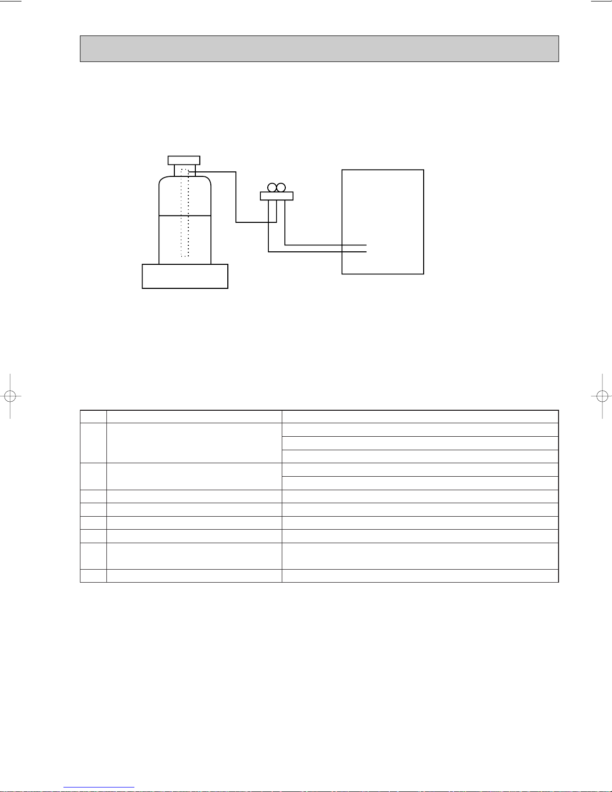
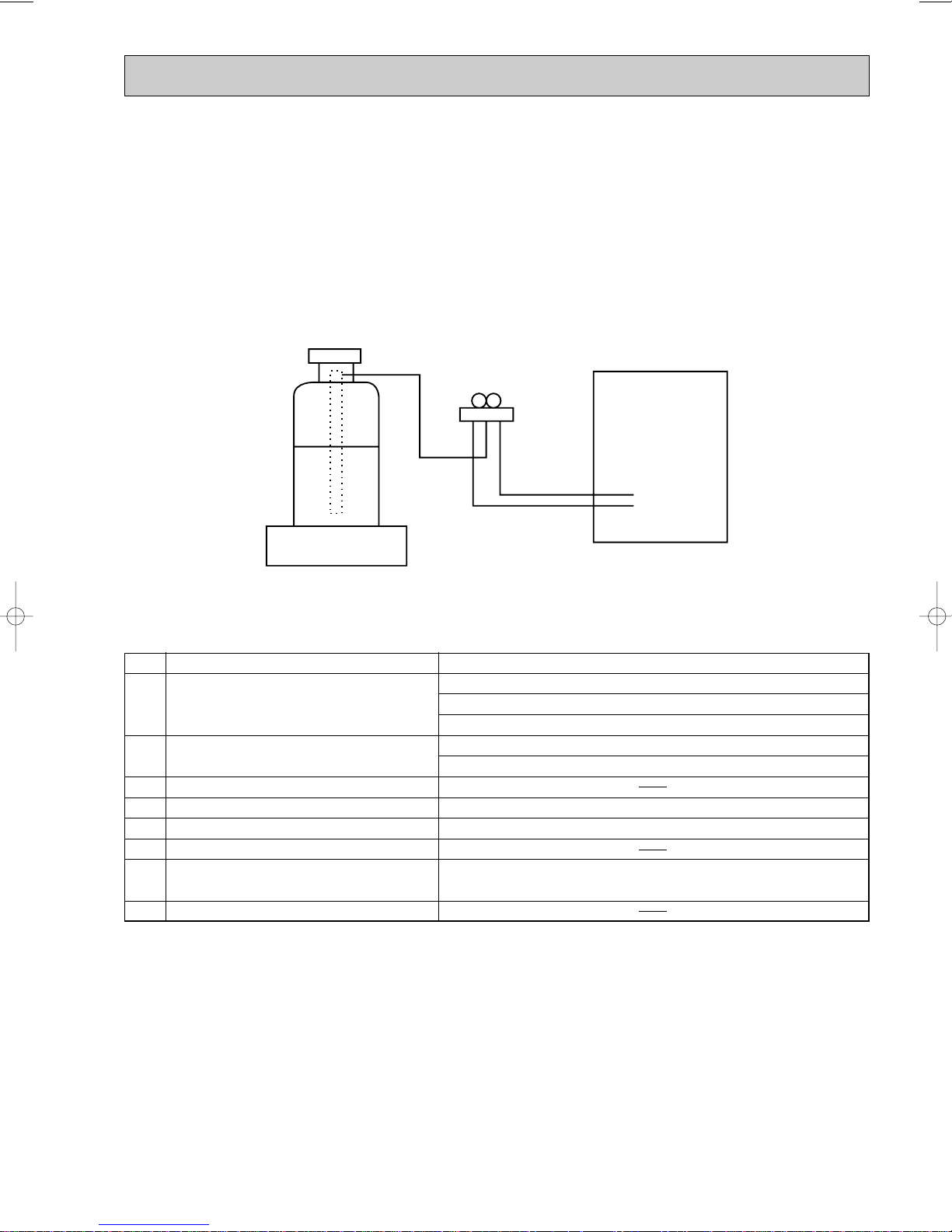
[2] Refrigerant recharging
Gravimeter
Unit
(1) Refrigerant recharging process
1Direct charging from the cylinder.
·R407C cylinder are available on the market has a syphon pipe.
·Leave the syphon pipe cylinder standing and recharge it.
(By liquid refrigerant)
(2) Recharge in refrigerant leakage case
·After recovering the all refrigerant in the unit, proceed to working.
·Do not release the refrigerant in the air.
·After completing the repair service, recharge the cycle with the specified amount of
liquid refrigerant.
[3] Service tools
Use the below service tools as exclusive tools for R407C refrigerant.
No. Tool name Specifications
1 Gauge manifold ·Only for R407C.
·Use the existing fitting SPECIFICATIONS. (UNF7/16)
·Use high-tension side pressure of 3.43MPa·G or over.
2 Charge hose ·Only for R407C.
·Use pressure performance of 5.10MPa·G or over.
3 Electronic scale
4 Gas leak detector ·Use the detector for R134a or R407C.
5 Adapter for reverse flow check. ·Attach on vacuum pump.
6 Refrigerant charge base.
7 Refrigerant cylinder. ·For R407C ·Top of cylinder (Brown)
·Cylinder with syphon
8 Refrigerant recovery equipment.
3
Cautions for units utilizing refrigerant R410A
Store the piping to be used during installation
indoors and keep both ends of the piping sealed
until just before brazing. (Leave elbow joints, etc.
in their packaging.)
Use ester oil, ether oil or alkylbenzene oil (small
amount) as the refrigerant oil applied to flares
and flange connections.
Charge refrigerant from liquid phase of gas
cylinder.
If the refrigerant is charged from gas phase, composition
change may occur in refrigerant and the efficiency will be
lowered.
Do not use refrigerant other than R410A.
If other refrigerant (R22 etc.) is used, chlorine in refrigerant can cause deterioration of refrigerant oil etc.
Use a vacuum pump with a reverse flow check
valve.
Vacuum pump oil may flow back into refrigerant cycle and
that can cause deterioration of refrigerant oil etc.
Use the following tools specifically designed for
use with R410A refrigerant.
The following tools are necessary to use R410A refrigerant.
Keep the tools with care.
If dirt, dust or moisture enter into refrigerant cycle, that can
cause deterioration of refrigerant oil or malfunction of compressor.
Do not use a charging cylinder.
If a charging cylinder is used, the composition of refrigerant will change and the efficiency will be lowered.
Flare tool
Electronic refrigerant
charging scale
Vacuum pump adaptor
Size adjustment gauge
Gauge manifold
Torque wrench
Gas leak detector
Charge hose
Tools for R410A
If dirt, dust or moisture enter into refrigerant cycle, that can
cause deterioration of refrigerant oil or malfunction of compressor.
If large amount of mineral oil enter, that can cause deterioration of refrigerant oil etc.
Do not use the existing refrigerant piping.
The old refrigerant and lubricant in the existing piping
contains a large amount of chlorine which may cause the
lubricant deterioration of the new unit.
Use “low residual oil piping”
If there is a large amount of residual oil (hydraulic oil, etc.)
inside the piping and joints, deterioration of the lubricant
will result.
Ventilate the room if refrigerant leaks during
operation. If refrigerant comes into contact with
a flame, poisonous gases will be released.
4
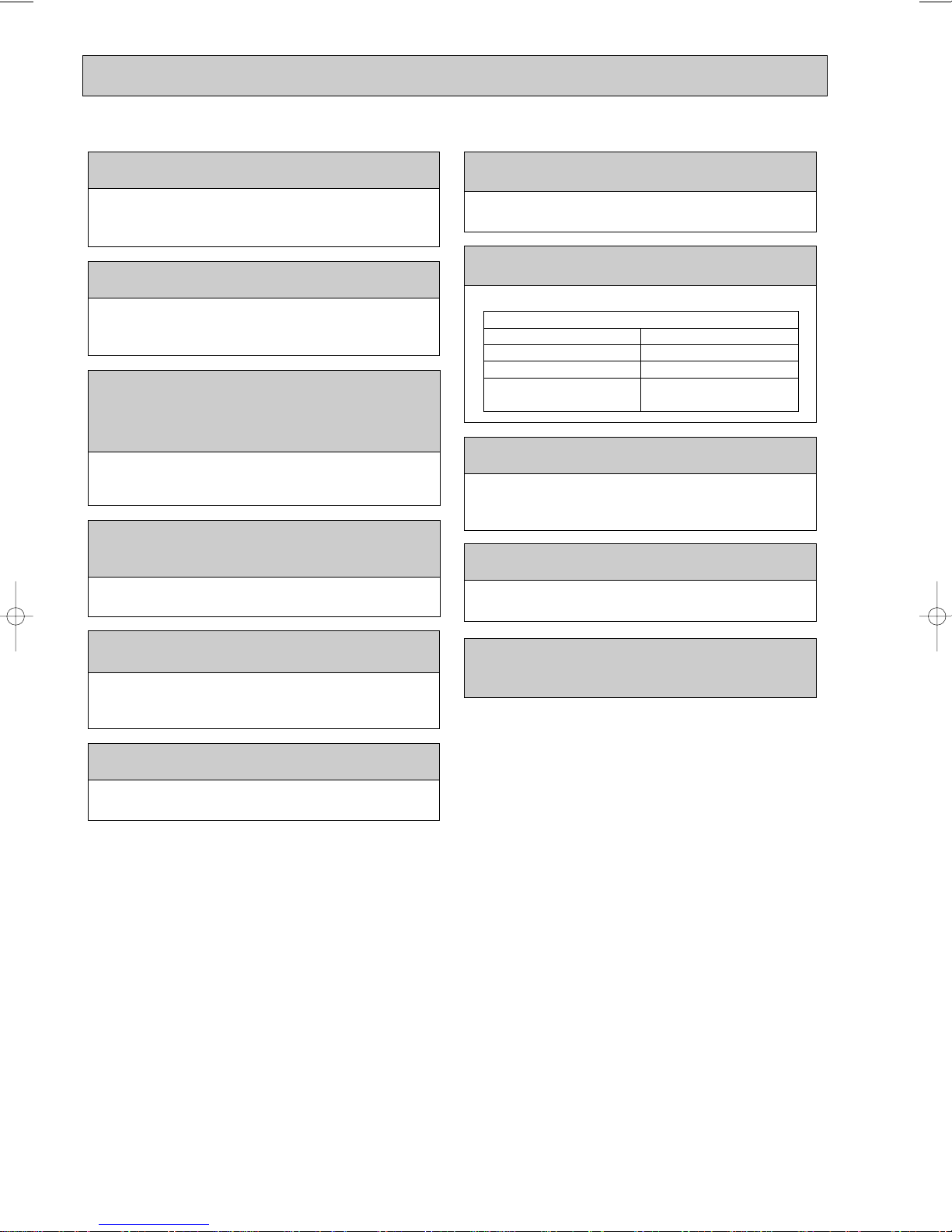
[1] Cautions for service
Gravimeter
Unit
(1) Perform service after collecting the refrigerant left in unit completely.
(2) Do not release refrigerant in the air.
(3) After completing service, charge the cycle with specified amount of refrigerant.
(4) When performing service, install a filter drier simultaneously.
Be sure to use a filter drier for new refrigerant.
[2] Additional refrigerant charge
When charging directly from cylinder
· Check that cylinder for R410A on the market is syphon type.
· Charging should be performed with the cylinder of syphon stood vertically. (Refrigerant is charged from liquid phase.)
[3] Service tools
Use the below service tools as exclusive tools for R410A refrigerant.
No. Specifications
1 Gauge manifold ·Only for R410A
·Use the existing fitting
·Use high-tension side pressure of 5.3MPa·G or over.
2 Charge hose ·Only for R410A
·Use pressure performance of 5.09MPa·G or over.
3 Electronic scale
4 Gas leak detector ·Use the detector for R134a, R407C or R410A.
5 Adaptor for reverse flow check ·Attach on vacuum pump.
6 Refrigerant charge base
7 Refrigerant cylinder ·Only for R410A Top of cylinder (Pink)
8 Refrigerant recovery equipment
specifications
Cylinder with syphon
. (UNF1/2)
5
2
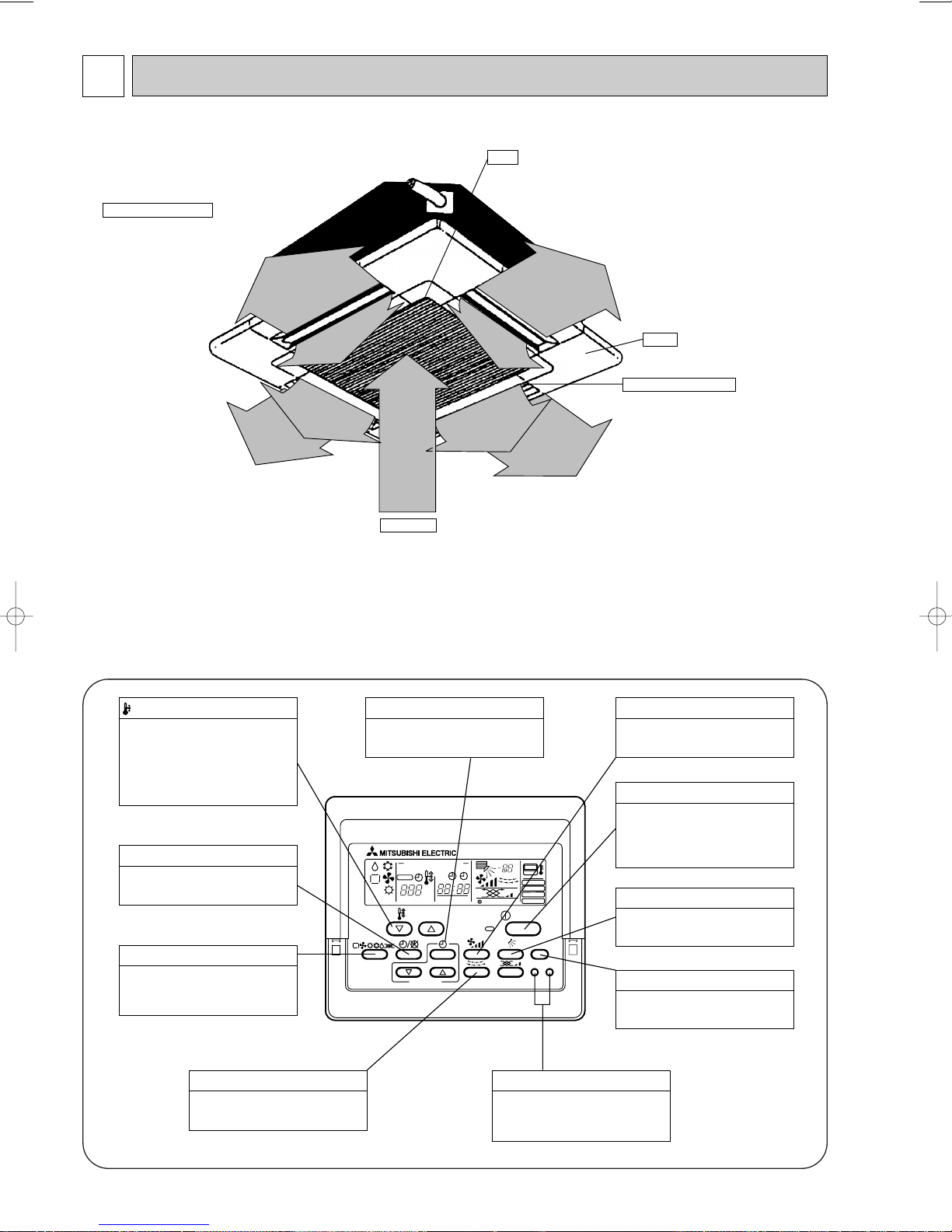
Auto Air Swing Vane
Disperses airflow up and
down and adjusts the angle
of airflow direction.
Grille
Filter
Remove dust and pollutants
from return air
Horizontal Air Outlet
Sets airflow horizontal automatically
during cooling or dehumidifying.
Air Intake
Returns air from room.
PAR-20MAA
ON/OFF
CENTRALLY CONTROLLED
ERROR CODE
CLOCK
ON OFF
˚C
CHECK
CHECK MODE
FILTER
TEST RUN
FUNCTION
˚C
1Hr.
NOT AVAILABLE
STAND BY
DEFROST
FILTER
CHECK TEST
TEMP.
TIMER SET
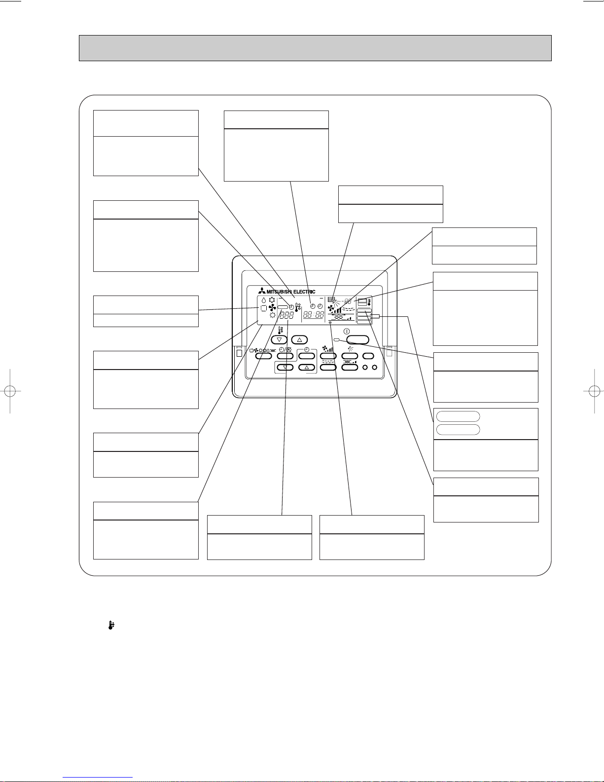
Press this button to switch between
cool,
dry, automatic and heat modes.
OPERATION SWITCH button
This sets the room temperature. The
temperature setting can be performed
in 1: units
Setting range
Cooler 19: to 30:
Heater 17: to 28:
TEMP. ADJUSTMENT button
This switches between continuous
operation and the timer operation.
TIMER button
This switches between the operation
and stop modes each time it is pressed.
The lamp on this button lights during
operation.
ON/OFF button
Only press this button to perform an
inspection check or test operation.
Do not use it for normal operation.
CHECK-TEST RUN button
This switch the horizontal fan motion
ON and OFF.
(Not available for this model.)
LOUVER button
This adjusts the vertical angle of the
ventilation.
AIR DIRECTION button
This resets the filter service indication
display
FILTER button
This sets the current time, start time
and stop time.
TIME SETTING button
This sets the ventilation fan speed.
AIR SPEED button
PART NAMES AND FUNCTIONS
● Indoor Unit
● Remote controller
Once the controls are set, the same operation mode can be repeated by simply pressing the ON/OFF button.
● Operation buttons
Note : This figure is PAR-20MAA. Refer to each remote controller manual for the details.
6
● Display
PAR-20MAA
ON/OFF
CENTRALLY CONTROLLED
ERROR CODE
CLOCK
ON OFF
˚C
CHECK
CHECK MODE
FILTER
TEST RUN
FUNCTION
˚C
1Hr.
NOT AVAILABLE
STAND BY
DEFROST
FILTER
CHECK TEST
TEMP.
TIMER SET
CENTRALLY
CONTROLLED display
This indicates when the unit is con-
trolled by optional features such as
central control type remote
controller.
TIMER display
This indicates when the continuous
operation and time operation modes
are set.
It also display the time for the timer
operation at the same time as when
it is set.
OPERATION MODE display
This indicates the operation mode.
STANDBY display
The [STANDBY] symbol is only dis-
played from the time the heating
operation starts until the heated air
begins to blow.
DEFROST display
This indicates when the defrost
operation is performed.
CLOCK display
The current time , start time and stop
time can be displayed in ten second
intervals by pressing the time switch
button. The start time or stop time is
always displayed during the timer
operation.
In this display example on the bottom left, a condition where all display lamps light is shown for explanation purposes although this differs
from actual operation.
AIR DIRECTION display
This displays the air direction.
AIR SPEED display
The selected fan speed is displayed.
ROOM TEMPERATURE display
The temperature of the suction air
is displayed during operation. The
display range is 8°C to 39°C. The
display flashes 8°C when the actual
temperature is less than 8°C and
flashes 39°C when the actual temperature is greater than 39°C.
Operation lamp
This lamp lights during operation,
goes off when the unit stops and
flashes when a malfunction occurs.
CHECK MODE
TEST RUN
This display lights in the check
mode or when a test operation is
performed.
display
CHECK display
This indicates when a malfunction
has occurred in the unit which should
be checked.
Caution
● Only the Power display lights when the unit is stopped and power supplied to the unit.
● When the central control remote control unit, which is sold separately, is used the ON-OFF button, operation switch button
and TEMP. adjustment button do not operate.
● “NOT AVAILABLE” is displayed when the Air speed button is pressed. This indicates that this room unit is not equipped with
the fan direction adjustment function and the louver function.
● When power is turned ON for the first time, it is normal that “H0” is displayed on the room temperature indication (For max.
2minutes). Please wait until this “H0” indication disappear then start the operation.
SET TEMPERATURE display
This displays the selected setting
temperature.
POWER display
This lamp lights when electricity is
supplied to the unit.
7
FILTER display
This lamp lights when the filter need
to be cleaned.
3
Item
kW
kW
kW
kW
A
A
—
mm
mm
mm
—
—
k/min
Pa
kW
—
—
[mm(in.)
[mm(in.)
[mm
dB
kg
Cooling capacity
Power
Heat exchanger
Insulator
Air filter
Fan ✕ No
Air flow W3
Pipe
dimensions
Unit drain pipe size
Noise level W3
Product weight
Exterior
(munsell symbol)
Fan motor
output
External
static pressure
Liquid
side
Gas
side
Heating capacity
F
a
n
Dimensions
Height
Width
Depth
Electric characteristic
Input
Cooling
Heating
Cooling
Heating
Current
PLFY-P40VAM-E.UK
PLFY-P50VAM-E.UK
PLFY-P32VAM-E.UK
PLFY-P63VAM-E.UK
3.6
4.0
0.12
0.12
0.59
0.59
14-13-12-11
31-29-28-27
0.14
0.14
0.68
0.68
Unit : Galvanized sheets with gray heat insulation Grills : ABS resin Munsell<0.70Y 8.59/0.97>
258<30>
840<950>
840<950>
Cross fin
Turbo fan ✕ 1
16-14-13-12
0
0.070
Polyethylene sheet
PP honey comb fabric
O.D.32 (PVC pipe VP-25 connectable)
32-30-28-27
7.1
8.0
0.16
0.16
0.78
0.78
[15.88(5/8")
[9.52(3/8")
33-31-29-28
Single phase 220-230-240V 50Hz
Single phase 220V 60Hz
V
·Hz
[12.7(1/2") / [15.88(5/8")
(Compatible)
[6.35(1/4")/[9.52(3/8")
(Compatible)
4.5
5.0
5.6
6.3
18-16-15-14
[12.7(1/2")
[6.35(1/4")
24<5>22<5>
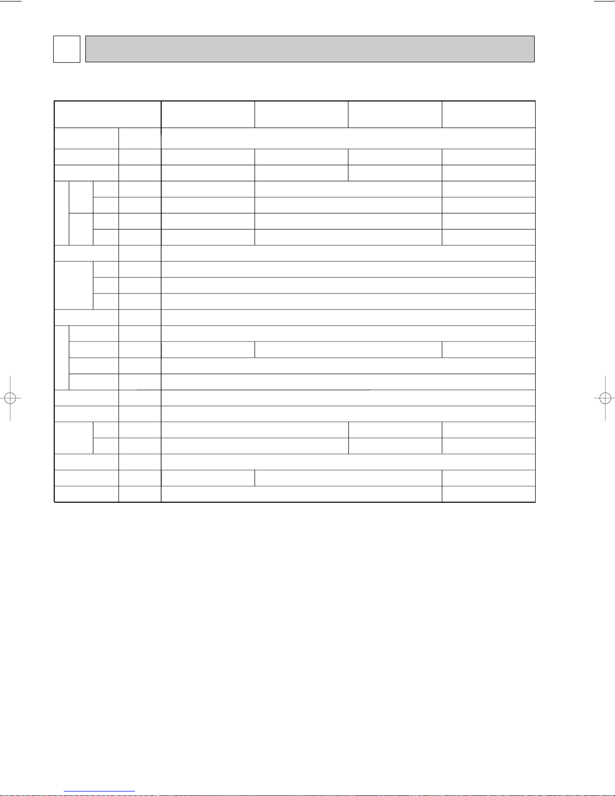
SPECIFICATIONS
3-1. Specifications
Note 1. Rating conditions(JIS B 8616)
Note 2. The number indicated in < > is just for the grille.
W 3. Air flow and the noise level are indicated as High-Medium1-Medium2-Low.
Cooling : Indoor : D.B. 27°C W.B. 19.0°C
Heating : Indoor : D.B. 20°C
outdoor : D.B. 35°C
outdoor : D.B. 7°C W.B. 6°C
8

Item
kW
kW
kW
kW
A
A
—
mm
mm
mm
—
—
k/min
Pa
kW
—
—
[mm(in.)
[mm(in.)
[mm
dB
kg
Cooling capacity
Power
Heat exchanger
Insulator
Air filter
Fan ✕ No
Air flow W3
Pipe
dimensions
Unit drain pipe size
Noise level W3
Product weight
Exterior
(munsell symbol)
Fan motor
output
External
static pressure
Liquid
side
Gas
side
Heating capacity
F
a
n
Dimensions
Height
Width
Depth
Electric characteristic
Input
Cooling
Heating
Cooling
Heating
Current
PLFY-P80VAM-E.UK
PLFY-P100VAM-E.UK PLFY-P125VAM-E.UK
9.0
10.0
0.18
0.18
0.86
0.86
258<30>
22-20-18-16
0.070
15.88(5/8")
37-35-32-30
24<5>
11.2
12.5
0.30
0.30
1.43
1.43
Unit : Galvanized sheets with gray heat insulation Grills : ABS resin Munsell<0.70Y 8.59/0.97>
840<950>
840<950>
Cross fin
Turbo fan ✕ 1
27-25-22-19
0
Polyethylene sheet
PP honey comb fabric
9.52(3/8")
O.D.32 (PVC pipe VP-25 connectable)
41-39-36-33
14.0
16.0
0.34
0.34
1.64
1.64
298<30>
0.120
29-27-24-21
43-41-38-35
Single phase 220-230-240V 50Hz
Single phase 220V 60Hz
V
·Hz
32<5>
[15.88(5/8") / [19.05(3/4")
(Compatible)
Note 1. Rating conditions(JIS B 8616)
Note 2. The number indicated in < > is just for the grille.
W 3. Air flow and the noise level are indicated as High-Medium1-Medium2-Low.
Cooling : Indoor : D.B. 27°C W.B. 19.0°C
Heating : Indoor : D.B. 20°C
outdoor : D.B. 35°C
outdoor : D.B. 7°C W.B. 6°C
9
3-2. Electrical parts specifications
Parts name
Model
Symbol
TH21
TH22
TH23
FUSE
MF
C
MV
DP
DS
LEV
H2
TB2
TB5
TB15
Resistance 0:/15k", 10:/9.6k", 20:/6.3k", 25:/5.4k", 30:/4.3k", 40:/3.0k"
Resistance 0:/15k", 10:/9.6k", 20:/6.3k", 25:/5.4k", 30:/4.3k", 40:/3.0k"
Resistance 0:/15k", 10:/9.6k", 20:/6.3k", 25:/5.4k", 30:/4.3k", 40:/3.0k"
250V 6.3A
240V 21.8W
(L, N, ;) Rated to 330V 30A W
(M1, M2, S) Rated to 250V 20A W
(1, 2) Rated to 250V 10A W
Liquid pipe thermistor
Gas pipe thermistor
Fan motor capacitor
Vane motor
Drain-up mechanism
Drain sensor
Linear expansion valve
PLFY-P40VAM-E.UKPLFY-P32VAM-E.UK PLFY-P50VAM-E.UK PLFY-P63VAM-E.UK
Room temperature
thermistor
Fuse
(Indoor controller board)
Fan motor
(with inner-thermostat)
Inner-thermostat
Electric heater
(Condensation proof)
Power supply terminal
block
Transmission terminal
block
MA remote controller
terminal block
6-pole OUTPUT 70W
D17B6P70MS
MSBPC20M04
DC12V 300
"
/phase
PLD-12230ME-1
INPUT 12/10.8W 24R/Hr
Thermistor resistance 0:/6k", 10:/3.9k", 20:/2.6k", 25:/2.2k", 30:/1.8k", 40:/1.3k"
DC12V Stepping motor drive port dimension 5.2" (0~2000pulse)
EDM-40YGME
OFF 130: i 5:
ON 90: i 20:
3.0+ ✕ 440V
W Note : Refer to WIRING DIAGRAM for the supplied voltage.
10
 Loading...