

Page 1
Air-Conditioners For Building Application
INDOOR UNIT
PLFY-NLMD
FOR INSTALLER
据付工事者へ
INSTALLATION MANU AL
For safe and correct use, please read this installation manual thoroughly before installing the air-conditioner unit. How to install an
optionally available panel is also described in the panel installation manual.
How to install outdoor units and items about the multi-unit system are described in the outdoor unit installation manual.
∗ Remote controller (PAR-F25M or PAR-F26M) is available as an optional remote controller.
ENGLISH
日本語
据付説明書
据付の前に正しく安全にお使いいただくためこの取扱説明書を必ずお読みください。室外側ユニットの据付方法およびマルチシ
ステム関連の項目は、室外側ユニットの据付説明書に記載されております。また、別売部品のパネルの据付はパネルの据付説明
書に記載されております。
∗ リモコン(PAR-F25M又は、PAR-F26M)は別売品です。
Page 2

Contents
1. Safety precautions ...................................................................... 3
1.1. Before installation and electric work................................3
1.2. Before getting installed.................................................... 3
1.3. Before getting installed (moved) - electrical work .......... 4
1.4. Before starting the test run.............................................. 4
2. Indoor unit accessories ............................................................... 5
3. Selecting an installation site ........................................................ 5
3.1. Securing installation and service space ..........................5
3.2. Split flow duct end connection - fresh air intake ............. 5
3.3. Combining indoor units with outdoor units ..................... 6
4. Fixing hanging bolts .................................................................... 6
4.1. Fixing hanging bolts ........................................................6
4.2. Ceiling hole and hanging bolt positions...........................6
5. Installing the unit ......................................................................... 7
ENGLISH
5.1. Hanging the unit body .....................................................7
5.2. Confirming the unit’s position and fixing hanging bolts .. 8
6. Refrigerant pipe and drain pipe specifications ............................8
6.1. Refrigerant pipe and drain pipe specifications ............... 8
6.2. Refrigerant pipe , drain pipe and filling port ................... 8
6.3. Request for refrigerant piping connection ...................... 9
7. Connecting refrigerant pipes and drain pipes ............................ 10
7.1. Refrigerant piping work .................................................10
7.2. Drain piping work .......................................................... 10
7.3. Confirming drain discharge ........................................... 11
8. Electrical wiring ......................................................................... 11
8.1. Power supply wiring ......................................................12
8.2. Connecting remote controller, indoor and outdoor
transmission cables ...................................................... 12
8.3. Connecting electrical connections................................. 13
8.4. Setting addresses ......................................................... 14
8.5. Sensing room temperature with the built-in sensor in a
remote controller ...........................................................14
9. Test run ..................................................................................... 15
2
Page 3
1. Safety precautions
1.1. Before installation and electric work
s Before installing the unit, make sure you read all the
“Safety precautions”.
s The “Safety precautions” provide very important
points regarding safety. Make sure you follow them.
Symbols used in the text
Warning:
Describes precautions that should be observed to prevent danger
of injury or death to the user.
Caution:
Describes precautions that should be observed to prevent damage
to the unit.
Symbols used in the illustrations
: Indicates an action that must be avoided.
: Indicates that important instructions must be followed.
: Indicates a part which must be grounded.
: Indicates that caution should be taken with rotating parts. (This
symbol is displayed on the main unit label.) <Color: Yellow>
: Indicates that the main switch must be turned off before servic-
ing. (This symbol is displayed on the main unit label.) <Color:
Blue>
: Beware of electric shock. (This symbol is displayed on the main
unit label.) <Color: Yellow>
Warning:
Carefully read the labels affixed to the main unit.
Warning:
• The unit must be securely installed on a structure that can sus-
tain its weight. If the unit is mounted on an unstable structure, it
may fall down causing injuries.
• Use only specified cables for wiring. The connections must be
made securely without pulling on the terminals. Improper con-
nections or installation may generate heat or cause a fire.
• The unit should be installed according to the instructions in or-
der to minimize the risk of damage from earthquakes, typhoons
or strong winds. An improperly installed unit may fall down and
cause damage or injuries.
• When installing an optional air cleaner or humidifier, be sure to
use only products specified by Mitsubishi.
All accessories must be installed by an authorized technician.
The user must not try to install accessories. Improperly installed
accessories can cause water leakage, electric shock or fire.
• Do not turn on the power until installation has been completed.
Failure to do so may cause an electric shock or fire.
• The unit should not be installed by the user. Ask the dealer or
an authorized technician to install the unit. If the unit is installed
improperly, water leakage, electric shock or fire may result.
• Use only accessories authorized by Mitsubishi Electric and ask
the dealer or an authorized technician to install them. If acces-
sories are installed improperly, water leakage, electric shock or
fire may result.
• The Installation Manual details the suggested installation
method. Any structural alteration necessary for installation must
comply with local building code requirements.
• The user should never attempt to repair the unit or transfer it to
another site. If the unit is repaired improperly, water leakage,
electric shock or fire may result. If the air conditioner must be
repaired or moved, consult the dealer.
• All electric work must be performed by a licensed technician,
according to local regulations and the instructions given in this
manual.
The units should be powered by dedicated power lines. Power
lines with insufficient capacity or improper electrical work may
result in electric shock or fire.
• The terminal bed cover of the outdoor unit must be firmly attached to prevent entry of dust and moisture. Improper mounting of the cover can cause electric shock or fire.
• Use only the specified refrigerant (R-22) to charge the refrigerant circuit. Do not mix it with any other refrigerant and do not
allow air to remain in the circuit. Air enclosed in the circuit can
cause pressure peaks resulting in a rupture and other hazards.
• If the air conditioner is installed in a small room, measures must
be taken to prevent the refrigerant concentration in the room
from exceeding the safety limit in the event of refrigerant leakage.
Consult the dealer regarding the appropriate measures to prevent the allowable concentration from being exceeded. Should
the refrigerant leak and cause the concentration limit to be exceeded, hazards due to lack of oxygen in the room could result.
• Ventilate the room if refrigerant leaks during operation.
If the refrigerant comes in contact with a flame, poisonous gases
will be released.
1.2. Before getting installed
Caution:
• Do not install the equipment where combustible gas may leak
and accumulate resulting in fire.
• Do not keep food, plants, caged pets, artwork or precision instruments in the indoor unit’s direct airflow or too close to the
unit, as these items can be damaged by temperature changes
or dripping water.
• When the room humidity exceeds 80% or when the drain pipe is
clogged, water may drip from the indoor unit. Do not install the
indoor unit where such dripping could cause damage.
The outdoor unit produces condensation during the heating operation. Make sure to provide drainage around the outdoor unit
if such condensation is likely to cause damage.
• This air conditioner should not be installed in areas exposed to
thick steam, volatile oil (including machine oil) or sulphuric
smoke, as this could significantly reduce its performance and
damage the internal parts.
• When installing the unit in a hospital, communication station,
etc., provide sufficient protection against noise.
The air-conditioner may operate erroneously or fail to operate
because it is affected by inverter equipment, private power generator, high-frequency medical equipment or radio-used communications equipment. Conversely, it may affect such equipment, creating noise to disturb medical treatment or image
broadcasting.
ENGLISH
3
Page 4

1.3. Before getting installed (moved) electrical work
Caution:
• When installing the power lines, do not apply tension to the ca-
bles, as this could loosen the connections, generate heat and
cause a fire.
• Use only a fuse of specified capacity. A fuse of larger capacity
or a steel or copper wire could cause a general unit failure or
fire.
• Make sure to install an earth leakage breaker as this device helps
reduce the risk of electric shocks. Installation of an earth leakage breaker is mandatory in some areas.
• For the power lines, use standard cables of sufficient current
capacity. Otherwise, current leakage, overheating or fire may
occur.
• Be very careful about product transportation.
Only one person should not carry the product if it is more than
20 kg.
Some products use PP bands for packaging. Do not use any PP
band for a means of transportation.
Do not touch the heat exchanger fins with your bear hands. Doing
so may cut your hands.
Tear off and discard plastic packaging bags so that children will
not play any of them. If children play a plastic bag which was
not torn off, it may cause a risk of suffocation .
• The base and attachments of the outdoor unit should be periodically checked for looseness, cracks or other damage. If such
defects are left uncorrected, the unit may fall and cause personal injury or property damage.
• Be sure to safely dispose of the packaging materials. Packaging materials, such as catches and other metal or wooden parts,
may cause stabs or other injuries.
Earth connection
Caution:
Make sure to install a grounding line. Do not connect the ground-
ENGLISH
ing line to gas or water pipes, lightning conductors or telephone
grounding lines. Improper grounding may cause an electric shock.
Drain piping
Caution:
• Install drain piping according to this Installation Manual to ensure proper drainage. Place thermal insulation on the pipes to
prevent condensation. Improper drain piping may cause water
leakage and damage to furniture or other possessions.
• Thermal insulation of the drain pipes is necessary to prevent
dew condensation. If the drain pipes are not properly insulated,
condensation will result and drip on the ceiling, floor or other
possessions.
Other
Caution:
• Do not wash the air conditioner units. Washing them may cause
an electric shock.
1.4. Before starting the test run
Caution:
• After completing installation work, make sure that refrigerant
gas is not leaked.
If refrigerant gas is leaked and exposed to fan heater, stove,
oven and so on, it may generate noxious gases.
• Before starting operation, check that all panels, guards and other
protective parts are correctly installed. Rotating, hot or high voltage parts can cause injuries.
• Do not touch the refrigerant pipes with bare hands during operation. The refrigerant pipes are sometimes hot and sometimes
cold depending on the condition of the flowing refrigerant. Your
hands may suffer burns or frostbite if you touch the pipes.
• Turn on the main power switch more than twelve hours before
starting operation. Starting operation just after turning the main
power switch on can result in severe damage to internal parts.
Keep the main power switch turned on during the operation season.
• Keep the outlets and inlets free of obstacles. Otherwise, the performance may be reduced or operation may stop.
• Do not touch any switch with wet fingers, as this can cause an
electric shock.
• Do not operate the air conditioner without the air filter set in
place. Dust may accumulate, and cause a failure.
• After stopping operation, be sure to wait for five minutes before
turning off the main power switch. Otherwise, water leakage or
unit failure may occur.
4
Page 5
2. Indoor unit accessories
The unit is provided with the following accessories:
Part No.
1 Insulated pipe (small) 1
2 Insulating cover 1
3 Tie band (large) 6
4 Drain hose 1
5 Washer 8
Accessories Qty Place to Set
On the body frame
casing
3. Selecting an installation site
• Select a location so that air can be blown into all corners of the room.
• Avoid locations exposed to outside air.
• Select a location free of obstructions to the airflow in and out of the
unit.
• Avoid locations exposed to steam or oil vapour.
• Avoid locations where combustible gas may leak, settle or be gener-
ated.
• Avoid installation near machines emitting high-frequency waves (highfrequency welders, etc.)
• Avoid locations where the airflow is directed at a fire alarm sensor.
(Hot air could trigger the alarm during the heating operation.)
• Avoid places where acidic solutions are frequently handled.
• Avoid places where sulphur-based or other sprays are frequently used.
Warning:
Install the indoor unit on a ceiling strong enough to sustain its
weight.
If the ceiling lacks strength, it may cause the unit to fall down, resulting in an injury.
3.1. Securing installation and service
space
Part No.
6 Tie band (small) 2
7 Insulated pipe (large) 1
8 Piping manual 1
9 Tape 1
10
Model name 20 · 25 · 32 40 · 50 63 · 80 100 · 125
A 1060 1300 1650 2000
B More than 1000
C More than 500
D Lap: 20
E 360
Accessories Qty Place to Set
Connector for drain pump test
1
On the body frame
casing
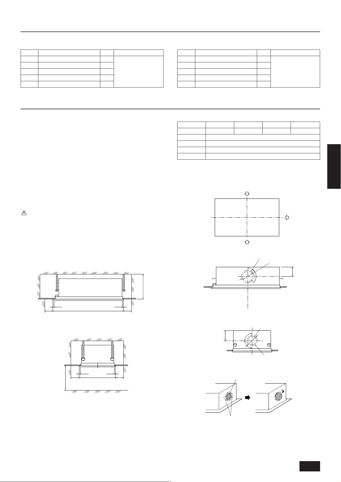
3.2. Split flow duct end connection - fresh
air intake
A
D
A
B
45°
ø224
ENGLISH
E
D
C
B
• Select a blowout direction suited for room shape, installation site and
so on.
• Piping, wiring and maintenance are all done on the bottom and the
side. So, secure the space given above for such work. Also, taking
into consideration serviceability and safety in hanging, secure as large
space as possible.
A
D
C
670
D
C
D
C
181
E
F
D
90˚
90˚
90°
C
ø172
G
145
5
Page 6

• Knockouts are provided at each position as shown in the figure. Use
them for your purposes when installing the unit.
A Split flow duct end connection
B Split flow duct end connection (ø200 knockout on both sides)
C Fresh air intake (ø150 knockout)
D Fresh air intake
E To be cut
F 4-ø2.9 mounting hole
G 4-ø2.9 mounting hole
4. Fixing hanging bolts
Notes:
• Affixed on the back surface of each split flow duct end connection is insulating material. Use a cutter knife to cut the insulating material along the end connection.
• To adjust the fresh air intake capacity, cut the two places as
shown in the figure at right, and rotate the intake.
3.3. Combining indoor units with outdoor
units
For combining indoor units with outdoor units, refer to the outdoor unit
installation manual.
4.1. Fixing hanging bolts
(Use M10 hanging bolts. The bolts should be procured locally.)
ENGLISH
(Give site of suspension strong structure.)
Hanging structure
• Ceiling: The ceiling structure varies from building to one another. For
detailed information, consult your construction company.
1 Reinforcing the ceiling with additional members (edge beam, etc.)
must be required to keep the ceiling at level and to prevent the ceiling
from vibrations.
2 Cut and remove the ceiling members.
3 Reinforce the ceiling members, and add other members for fixing the
ceiling boards.
For wooden construction
• Use the tie beam (for one story building) or second-floor beam (for
two story building) as strength members.
• To hang the air-conditioner, use a hard square timber of more than
6 cm if the distance between beams is less than 90 cm and a hard
square timber of more than 9 cm if the distance between beams is
less than 180 cm.
E
E
A
B
A Ceiling board
B Edge beam
C Tie beam
D Square timber for hanging the air conditioner
E Pitch
C
D
For reinforced concrete construction
• As shown in the figure below, fix the hanging bolts, or use square
timbers to fix the hanging bolts.
H
F
G
F Insert: 100 to 150 kg (1 piece) (field supply)
G M10 hanging bolt (field supply)
H Reinforcement
Product Weight (kg)
Model name 20 · 25 32 40 50 63
Body frame 24 25 33.5 35 39 41 56
Panel 7 7 8 8 10 10 11.5
80 100 · 125
4.2. Ceiling hole and hanging bolt posi-
tions
• Use the gage supplied with the panel to fix hanging bolts so that the
unit body and ceiling hole are positioned in place as shown in the
figure below. For how to use the gage, refer to the instruction manual
supplied with the panel.
Notes:
• The gage may expand or shrink with changes in the temperature and humidity. First be sure to check the product dimensions, and then use the gage.
• The ceiling hole is adjustable as shown in the figure below. Align
the centers of both ceiling hole and unit body so that the unit
body is not biased to the ceiling hole and that the gaps between
the ceiling hole edges and the unit body’s external dimensions
come to be identical.
6
Page 7

• Use M10 hanging bolts (for all bolts). (field supply)
A
• Each hanging bolt must extrude Cmm from the ceiling. It is possible
to slide the unit body 15 mm max. within part of the heights of the
unit body and decorative panel in order to make fine installation adjustments to the finished ceiling surface. Sliding the unit body and
incorporating a high-performance filter requires the dimensions given
in the figure below. To this, attach nuts which will fix a hanging bracket
as shown in the figure.
A
B
A
C
B
F
B
50±10
D
G
A
C
A Nut
B Washer (supplied with the unit body)
C Hanging bolt ø10 (M10 screw)
D Ceiling hole dimensions
E Hanging bolt pitch
F Hanging bolt
G Finished ceiling surface
H Hanging bracket
Model name 20 · 25 · 32 40 · 50 63 · 80 100 · 125
A 1020 1260 1610 1960
B 816 1056 1406 1756
• α indicates a range of 0 to 15 mm.
Installation
example
Dimension C 338
Dimension D 143 143+α
For not sliding unit body For sliding unit body
338+α
(353 Max.)
ENGLISH
H
D 630
E 550 4040
E B 102102
D A
5. Installing the unit
5.1. Hanging the unit body
s Bring the indoor unit to an installation site as it is packed.
s To hang the indoor unit, use a lifting machine to lift and pass
through the hanging bolts.
s Install the indoor unit before ceiling work.
s When lifting with a lifting machine, in order to protect against
damage, reverse the unit body as is packed with the packing
cap and lift it.
B
C
D
A Drain pipe side
B Unit body
C Packing cap
D Lifting machine
7
Page 8

5.2. Confirming the unit’s position and
38
35070
476
20 20630
60 60
C
550
606
70 178
192
338-3538
2903-1845
135
52
B
D
A
E
fixing hanging bolts
s Use the gage supplied with the panel to confirm that the unit
body and hanging bolts are positioned in place. If they are not
positioned in place, it may result in dew drops due to wind leak.
Be sure to check the positional relationship.
s Use a level to check that the surface indicated by A is at level.
Ensure that the hanging bolt nuts are tightened to fix the hanging bolts.
s To ensure that drain is discharged, be sure to hang the unit at
level using a level.
Caution:
Be sure to install the unit body at level.
ENGLISH
6. Refrigerant pipe and drain pipe specifications
A
B Indoor unit’s bottom surface
(Surface to which a decorative panel is attached)
B
To avoid dew drops, provide sufficient antisweating and insulating work
to the refrigerant and drain pipes.
When using commercially available refrigerant pipes, be sure to wind
commercially available insulating material (with a heat-resisting temperature of more than 100°C and thickness given below) onto both liquid and
gas pipes.
Be also sure to wind commercially available insulating material (with a
form polyethylene’s specific gravity of 0.03 and thickness given below)
onto all pipes which pass through rooms.
1 Select the thickness of insulating material by pipe size.
Pipe size Insulating material’s thickness
6.4 mm to 25.4 mm More than 10 mm
28.6 mm to 38.1 mm More than 15 mm
2 If the unit is used on the highest story of a building and under condi-
tions of high temperature and humidity, it is necessary to use pipe
size and insulating material’s thickness more than those given in the
table above.
3 If there are customer’s specifications, simply follow them.
6.1. Refrigerant pipe and drain pipe
specifications
Model
Item
Refrigerant pipe
(Flare connection)
Drain pipe VP-25
Liquid pipe ø6.35 ø9.52
Gas pipe ø12.7 ø15.88 ø19.05
20·25·32·40 50·63·80 100 · 125
6.2. Refrigerant pipe , drain pipe and filling port
A Refrigerant pipe (liquid pipe): HP
B Drain pipe
C Hanging bolt pitch
D Refrigerant pipe (gas pipe): LP
E Filling port
8
Page 9

6.3. Request for refrigerant piping connection
C
B
A
DE
F
G
*2
20
20
20
20
C
B
A
*3
*4
Description of parts to be used
No.
1
2
3
Work procedures
Mount the provided pipe insulation (1) on the liquid pipe
of the refrigerant piping, and
then mount the flare insulation (2) on the gas pipe.
Fixing of insulated pipe
Fixing of flare insulation
Detail of work
“INNER” and “OUTER” are marked on
the inside of the flare insulation. Mount
the portion marked “INNER” near the
unit body and the portion marked
“OUTER” on the field piping side.
• Fasten the insulated pipe with the in-
sulation tape.
• Firmly secure the insulation with the
provided tie band (4) at the position
indicated on the drawing.
• Fasten the flare insulation with the pro-
vided tape (3).
• Fasten with the provided tie band (4)
at the position indicated on the drawing.
Item to be observed
• Using the flare insulation of a different model
may result in condensation forming. Check
the model name on the insulation and be sure
to use the correct one.
• To prevent a gap from forming near the unit’s
side plate, be sure that the flare insulation
firmly contacts the unit’s side plate before
mounting.
• Incorrectly mounting the “INNER” and
“OUTER” sides of the insulation may result
in condensation forming.
Seal the slit securely so that there are no openings. Be sure to mount the insulation so that
the slit is on the top.
Seal the slit securely so that there are no openings. Be sure to mount the insulation so that
the slit is on the top.
Reference drawing
Fig-1
Fig-2 (Note *2)
Fig-2
Fig-3 (Note *3)
Fig-3 (Note *4)
ENGLISH
A
C
D
L
A “0-0 gas” mark
B “INNER” mark
C “OUTER” mark
D Flare insulation (2)
E Refrigerant piping (gas)
F Refrigerant piping (liquid)
G Field refrigerant piping
H Pipe insulation (1)
I Insulation material
J Flare
K Pull in this direction.
L Insulation material
M Flare
N There must be no gap.
O Move to the original position.
B
G
O
K
Fig-1
*1
N
M
E
F
H
Fig-2 (figure showing the flare insulation)
JI
A Field refrigerant piping E INNER
B There must be no gap. F Unit body
C Unit body plate G Provided flare insulation (2)
D OUTER
Fig-3
A Tape (3) C Provided tie band (4)
B Fasten with tape.
Notes:
*1 Insert the flare nut into the field refrigerant piping. Pull the
insulation material back at the area where it will be flared,
then return it to its original position after performing the
flare work.
Exposing copper piping may result in condensation form-
ing. Be extremely careful when performing this operation.
*2 There must be no gap.
*3, *4 There must be no gap. Slit should be on the top.
9
Page 10

7. Connecting refrigerant pipes and drain pipes
7.1. Refrigerant piping work
This piping work must be done in accordance with the installation manual
for the outdoor unit.
• For constraints on pipe length and allowable difference of elevation,
refer to the outdoor unit manual.
• The method of pipe connection is flare connection.
H
I
Cautions on refrigerant piping
ss
s Be sure to use non-oxidative brazing for brazing to ensure that
ss
no foreign matter or moisture enter into the pipe.
ss
s Be sure to apply refrigerating machine oil over the flare connec-
ss
tion seating surface and tighten the connection using a double
spanner.
ss
s Provide a metal brace to support the refrigerant pipe so that no
ss
ENGLISH
load is imparted to the indoor unit end pipe. This metal brace
should be provided 50 cm away from the indoor unit’s flare connection.
Warning:
Do not mix anything other than the specified refrigerant (R-22) into
the refrigerating cycle. Mixing air may cause the refrigerating cycle
to get abnormally high temperature, resulting in a burst.
7.2. Drain piping work
C
A B
A
1
A: 25 cm
B: 1.5 – 2 m
A Downward pitch of more than 1/100
B Insulating material
C Metal brace
E
F
2
B
DDD
G
J
C
D
K I
C: 30 cm
G Drain hose (Accessory)
ss
s Be sure to use the supplied drain hose (Accessory).
ss
H Less than 300 mm
I Hard vinyl chloride 90° elbow (field supply)
J Hard vinyl chloride (VP-25) (field supply)
K Tie band (small) (Accessory)
ss
s Connect each connection with vinyl chloride adhesive. But never
ss
use any adhesive over the indoor unit discharge port. Otherwise the drain-up mechanism cannot be serviced later. Also,
the end connection may be eroded by resin and so cracked.
1. Ensure that the drain piping is downward (pitch of more than 1/100)
to the outdoor (discharge) side. Do not provide any trap or irregularity on the way. (1)
2. Ensure that any cross-wise drain piping is less than 20 m (excluding
the difference of elevation). If the drain piping is long, provide metal
braces to prevent it from waving. Never provide any air vent pipe.
Otherwise drain may be ejected.
3. Use a hard vinyl chloride pipe VP-25 (with an external diameter of 32
mm) for drain piping.
4. Ensure that collected pipes are 10 cm lower than the unit body’s
drain port as shown in 2.
5. Do not provide any odor trap at the drain discharge port.
6. Put the end of the drain piping in a position where no odor is generated.
7. Do not put the end of the drain piping in any drain where ionic gases
are generated.
8. The intake of the drain piping can be made 30 cm higher than the
drain discharge port. If there are some obstacles under the ceiling,
use elbows to make it at least height according to the site. (3)
3
D Indoor unit
E Take as large as possible. About 10 cm
F Collected pipes
10
Note:
If the rise portion is long, there will be a lot of returned water in an
operation stop, generating slime or odor during off-season. Ensure that the rise portion is at a minimum.
Caution:
Pipe the drain piping to ensure that it discharges drain, and insulate it to prevent dew condensation. A failure to the piping work
may cause water leakage and so wet your property.
Page 11

7.3. Confirming drain discharge
ss
s Make sure that the drain-up mechanism operates normally for
ss
discharge and that there is no water leakage from the connections.
• Be sure to confirm the above in a period of heating operation.
• Be sure to confirm the above before ceiling work is done in the case
of a new construction.
1. Plug the drain pump test connector (accessory) into the connector
on the same side as the control box. For more details, see the information on the control box cover.
2. Remove the polyethylene plug on the same side as the indoor unit
piping.
3. Fill water into the feed water pump using a feed water tank. In filling,
be sure to put the end of the pump or tank in a drain pan. (If the
insertion is incomplete, water may flow over the machine.)
4. Turn on the main power. The drain pump is forced to operate without
any remote controller operation. Make sure using a transparent hose
that drain is discharged.
5. After confirmation, turn off the main power, remove the connector,
and insert the polyethylene plug into its original position.
B
A Insert the pump’s end 2 to 4 cm.
B Remove the polyethylene plug.
C About 1000 ml
D Water
E Filling port
A
E
C
D
8. Electrical wiring
Precautions on electrical wiring
Warning:
Electrical work should be done by qualified electrical engineers in
accordance with “Engineering Standards For Electrical Installation”
and supplied installation manuals. Special circuits should also be
used. If the power circuit lacks capacity or has an installation failure, it may cause a risk of electric shock or fire.
1. Be sure to take power from the special branch circuit.
2. Be sure to install an earth leakage breaker to the power.
3. Install the unit to prevent that any of the control circuit cables (remote
controller, transmission cables) is brought in direct contact with the
power cable outside the unit.
4. Ensure that there is no slack on all wire connections.
5. Some cables (power, remote controller, transmission cables) above
the ceiling may be bitten by mouses. Use as many metal pipes as
possible to insert the cables into them for protection.
ENGLISH
6. Never connect the power cable to leads for the transmission cables.
Otherwise the cables would be broken.
7. Be sure to connect control cables to the indoor unit, remote controller, and the outdoor unit.
8. Put the unit to the ground on the outdoor unit side.
9. Select control cables from the conditions given in page 12.
Caution:
Be sure to put the unit to the ground on the outdoor unit side. Do
not connect the earth cable to any gas pipe, water pipe, lightening
rod, or telephone earth cable. Incomplete grounding may cause a
risk of electric shock.
11
Page 12

EF
C
20 ~ 80
Types of control cables
1. Wiring transmission cables
• Types of transmission cables
Design wiring in accordance with the following table <Table 1>.
• Cable diameter
More than 1.25 mm
<Table 1>
System configuration For a single-refrigerant system For a multi-refrigerant system
Transmission cable length Less than 120 m More than 120 m Regardless of length
Facility example
(for noise judgment)
Types of transmission
cables
ENGLISH
2. Remote controller cables
Types of cables
Cable diameter More than 0.5 to 0.75 mm
Length
2
Building, clinic, hospital or communica-
tions station without noise supposedly
Residence or independent
store without noise
VCTF, VCTFK, CVV, CVS,
VVR, VVF, VCT or shielding
wire CVVS or CPEVS
Network remote controller
Non-shielding wire for up to 10 m; the same specifications as “1.” Wiring transmission cables for
more than 10 m
2
Add any portion in excess of 10 m to within
the longest allowable transmission cable length
200 m (Shielding portion is more than 1.25 mm2)
generated from inverter equipment, private power generator, high-frequency
medical equipment, radio-used communications equipment and so on
Shielding wire CVVS or CPEVS
GH
All facilities
C
100 · 125
8.1. Power supply wiring
Power cable size (diameter) if optional heater is not attached: more
than 1.6 mm
AB
DE
CCCCCCC
E Switch 15 A
F Overcurrent protection 15 A
G Switch 30 A
H Overcurrent protection 20 A
Caution:
Do not use anything other than the correct capacity breaker and
fuse. Using fuse, wire or copper wire with too large capacity may
cause a risk of malfunction or fire.
A Switch 15 A
B Overcurrent protection 15 A
C Indoor unit
D Total operating current be less than 15 A
E Pull box
[Selecting non-fuse breaker (NF) or earth leakage breaker (NV)]
To select NF or NV instead of a combination of Class B fuse with switch,
use the following:
• In the case of Class B fuse rated 15 A or 20 A,
NF model name (MITSUBISHI): NF30-CS (15 A) (20 A)
NV model name (MITSUBISHI): NV30-CA (15 A) (20 A)
Use an earth leakage breaker with a sensitivity of less than 30 mA 0.1 s.
8.2. Connecting remote controller, indoor
and outdoor transmission cables
(Remote controller is optionally available.)
• Connect indoor unit TB5 and outdoor unit TB3. (Non-polarized 2-
wire)
The “S” on indoor unit TB5 is a shielding wire connection. For speci-
fications about the connecting cables, refer to the outdoor unit instal-
lation manual.
• Install a remote controller following the manual supplied with the re-
mote controller.
12
Page 13

[For using a network remote controller]
Connect the “M1” and “M2” on indoor unit TB5 to a network remote controller. (Non-polarized 2-wire) Connect the remote controller’s transmission cable within 10 m using a 0.75 mm2 core cable. If the distance is
more than 10 m, use a 1.25 mm2 junction cable.
8.3. Connecting electrical connections
(Be sure to prevent terminal screws from loosening.)
1. Remove 2 screws which secures the terminal bed box cover using a
screwdriver. (1)
AD
TB5
SM1M2
TB5
SM1M2
C
E
TB3
SM2M1
B
A Terminal bed for indoor transmission cable
B Terminal bed for outdoor transmission cable
C Indoor unit
D After indoor unit
E Field supply
F Network remote controller
• DC24 to 30 V between M1 and M2
Longest wiring length (L1+L2+L4 or L1+L3 or L2+L3+L4): less than 200 m
Length between indoor unit and remote controller (R): within 10 m
Notes:
*1 Put the transmission cable earth via the outdoor unit’s earth
terminal to the ground.
*2 If the remote controller cable exceeds 10 m, use a 1.25 mm2 di-
ameter cable over the exceeded portion, and add that exceeded
portion to within 200 m.
PARF25M/F26M
F
A
B
C
1
A Side frame
B Cover
C Cover securing screw (2 places)
2. As shown at 2, wire the power supply, transmission cable and re-
mote controller. There is no need to remove the terminal bed box.
D
G
Power Source
NL
Transmission
M1 M2 S
ENGLISH
[Constraints on transmission cable]
*1
G
H
III
L1
II
G Outdoor unit
H Earth
I Indoor unit
J Remote controller
K Non-polarized 2-wire
L2
K
L3
I
F
E
H
2
*2
JJ
J
L4
l
K
12
J
JF
<Viewed from bottom of the terminal bed box>
D Terminal bed for transmission cable
E Transmission cable
(To terminal bed for remote controller, indoor unit and BC controller)
F To single-phase power supply
G Terminal bed for power supply
H To terminal bed for outdoor transmission cable
(Use shielding earth cable
I Non-polarity
J Network remote controller
K DC24 to 30 V
on outdoor unit side.)
• Fix power source wiring to terminal bed box by using buffer bushing
for tensile force. (PG screw connection or the like.) Connect trans-
mission wiring to transmission terminal bed through the knockout
hole of terminal bed box using ordinary bushing.
13
Page 14

3. After wiring is complete, make sure again that there is no slack on
the connections, and attach the cover onto the terminal bed box in
the reverse order of removal.
Caution:
Wire the power supply so that no tension is imparted. Otherwise
disconnection, heating or fire may result.
• How to set addresses
Example: If Address is “3”, remain SW12 (for 1 to 9) at “0”, and match
SW11(for over 10) with “3”.
• The rotary switches are all set to “0” when shipped from the factory.
These switches can be used to set unit addresses at will.
• The determination of indoor unit addresses varies with the system at
site. Set them referring to technical data.
8.4. Setting addresses
(Be sure to operate with the main power turned OFF.)
ENGLISH
<Address board>
W254613G03
FP-AD-S
3
2
1
MADE IN JAPAN
@\ •
ON
1
JP1
Iv
V
W
SWCSWA
SW1
( • ‡/Ao • L)
0
240V 220V
SW14
SW5
yA
N0
“ß
N0
10
SW12
0
10
'¨Ah X
CN828161
SW11
0
˚
1
˚
CN62
JP2
JP3
JP4
8.5. Sensing room temperature with the
built-in sensor in a remote controller
If you want to sense room temperature with the built-in sensor in a remote controller, set SW1-1 on the control board to “ON”. The setting of
SW1-7 and SW1-8 as necessary also makes it possible to adjust the air
flow at a time when the heating thermometer is OFF.
14
Page 15

9. Test run
^]/ ~|
” @Ah XNo
G [No
A fi @Ah XNo
˚C
XC O
– @\˝Ł„æ
˚C
tB ^[
ª”‹†•
^C}[/A–
^] •
_[o[
^]• C •”•†
lbg [N R
PAR-F26M
W ˙
A – ^C}[
_ Ł•x
ZT[
tB ^[
_
^ ]
R
{
» Jn I„
hC[
' fi
@@@g[
g[ ı
P
Ł L ł
• C›ª
‹
A
D
B
C
E
2
5
9
4
3
6
ss
s Read the operation manual, too.
ss
• After installing, piping and wiring indoor and outdoor units, make sure
again that there is no refrigerant leakage, no slack on the power and
transmission cables, or no polarity incorrectness.
• Make sure using a DC 500 V megger that the resistance between
the power terminal bed and ground is more than 1.0 MΩ. If less than
1.0 MΩ, do not operate the unit.
Warning:
Never measure the insulation resistance of the terminal bed for
transmission cables.
Operational procedure
1 Turn ON power at least 12 hours before operation
2 Press [TEST RUN] button twice → displaying “TEST RUN” on the
screen
3 Press [Selecting operation] button → Check that wind is blowing out
4 Press [Selecting operation] button to change over to cooling (or heat-
ing) → Check that cool (or warm) air is blowing out
5 Press [Fan speed adjustment] button → Check that the wind speed
is changed
6 Press [Up/down airflow selection] button to change wind direction →
Check that the wind direction is adjustable for horizontal or downward blowing
7 → Check that the outdoor unit fan is operating
8 Check that interlocking devices such as ventilator are operating if
any
9 Press [ON/OFF] button to clear test run → Test run stops
A Lighting in operation
B Displaying inspection code
C Displaying remaining test run time
D Displaying indoor unit’s liquid pipe temperature
E Displaying test run
Notes:
• If the remote controller shows an inspection code or does not
operate normally, refer to the outdoor unit installation manual.
• The 2-hour-set timer is activated to automatically stop test run
after two hours.
• The remote controller displays the remaining test run time on
the time display section during test run.
• The remote controller displays the temperature of the indoor
unit’s liquid pipe on the temperature display section during test
run.
• Depending on the model, the remote controller displays “This
function is not available” when pressing the [Up/down airflow
selection] button. This is not a malfunction.
ENGLISH
15
Page 16

This product is designed and intended for use in the residential,
commercial and light-industrial environment.
WT02174X02
Please be sure to put the contact address/telephone number on
this manual before handing it to the customer.
HEAD OFFICE MITSUBISHI DENKI BLDG MARUNOUCHI TOKYO 100 TELEX J24532 CABLE MELCO TOKYO
Printed in Japan
 Loading...