

Mitsubishi Electric PLFY-P-NCMU-E, PLFY-(E)P-NEMU-E Installation Manual

MODEL
PLFY-P-NCMU-E
PLFY-(E)P-NEMU-E
NEW
AIR CONDITIONING SYSTEMS

1
CITY MULTI
MEE16K008_U
1. INDOOR UNITS
Ceiling cassette (4-way flow type) .......................................................................................................... 3
PLFY-P-NCMU-E, PLFY-(E)P-NEMU-E
ELECTRICAL CHARACTERISTICS....................................................................................................... 31

2
MEE16K008_U

3
Ceiling cassette (4-way flow type)
PLFY-P-NCMU-E, PLFY-(E)P-NEMU-E
MEE16K008_U
I.Ceiling cassette (4-way flow type)
1. SPECIFICATIONS........................................................................................................................................... 4
2. EXTERNAL DIMENSIONS .............................................................................................................................. 9
3. CENTER OF GRAVITY ................................................................................................................................... 12
4. ELECTRICAL WIRING DIAGRAMS................................................................................................................ 13
5. SOUND LEVELS ............................................................................................................................................. 16
5-1. Sound levels ............................................................................................................................................ 16
5-2. NC curves ................................................................................................................................................ 16
6. TEMPERATURE/AIRFLOW DISTRIBUTIONS ............................................................................................... 18
6-1. Temperature distributions ........................................................................................................................ 18
6-2. Airflow distributions.................................................................................................................................. 21
7. OUTDOOR AIR INTAKE AMOUNT & STATIC PRESSURE........................................................................... 24
8. OPTIONAL PARTS.......................................................................................................................................... 27
8-1. Optional parts line up for the Indoor unit.................................................................................................. 27
8-2. Air outlet shutter plate.............................................................................................................................. 27
8-3. High efficiency filter element.................................................................................................................... 28
8-4. Multi-function casement........................................................................................................................... 28
8-5. Wireless signal receiver........................................................................................................................... 29
8-6. Flange for fresh air intake ........................................................................................................................ 29
8-7. External heater adapter ........................................................................................................................... 30
1. SPECIFICATIONS
4
MEE16K008_U
I.Ceiling cassette (4-way flow type)1. SPECIFICATIONS
Model PLFY-P08NCMU-E PLFY-P12NCMU-E PLFY-P15NCMU-E
Power source 1-phase 208-230 V 60Hz
Cooling capacity *1 BTU / h 8,000 12,000 15,000
(Nominal) *1 kW 2.3 3.5 4.4
Power input kW 0.05 0.06 0.06
Current input A 0.23 0.28 0.28
Heating capacity *2 BTU / h 9,000 13,500 17,000
(Nominal) *2 kW 2.6 4.0 5.0
Power input kW 0.05 0.06 0.06
Current input A 0.23 0.28 0.28
External finish -
External dimension H x W x D in. 8-3/16 x 22-7/16 x 22-7/16 8-3/16 x 22-7/16 x 22-7/16 8-3/16 x 22-7/16 x 22-7/16
mm 208 x 570 x 570 208 x 570 x 570 208 x 570 x 570
Net weight lbs (kg) 34 (15.5) 37 (17) 37 (17)
Decoration Model SLP-15AAUW SLP-15AAUW SLP-15AAUW
panel External finish 6.4Y 8.9/0.4
Dimension in. 25/32 x 25-19/32 x 25-19/32 25/32 x 25-19/32 x 25-19/32 25/32 x 25-19/32 x 25-19/32
H x W x D mm 20 x 650 x 650 20 x 650 x 650 20 x 650 x 650
Net Weight lbs (kg) 7(3) 7(3) 7(3)
Heat exchanger Cross fin
FAN Type x Quantity Turbo fan x 1 Turbo fan x 1 Turbo fan x 1
External in.WG 0.000 (208V) 0.000 (208V) 0.000 (208V)
static press Pa 0 0 0
in.WG 0.000 (230V) 0.000 (230V) 0.000 (230V)
Pa 0 0 0
Motor type 1-phase induction motor
Motor output kW 0.015 0.020 0.020
Driving mechanism Direct-driven
Airflow rate cfm 280-320-350 320-350 -390 320-350-390
(Low-Mid-High) m3 / min 8.0-9.0-10.0 9.0-10.0-11.0 9.0-10.0-11.0
L / s 133-150-167 150-167-183 150-167-183
Sound pressure level (Low-Mid-High) dB <A> 29-32-38 (208-230V) 30-34-39 (208-230V) 31-35-40(208-230V)
(measured in anechoic room) dB <A> - - -
dB <A>---
Insulation material Polyethylene foam
Air filter PP honey comb fabric
Protection device Fuse
Refrigerant control device LEV
Connectable outdoor unit R410A CITY MULTI
Diameter of
refrigerant pipe
(O.D.)
Liquid (R410A) in. (mm) 1/4 (6.35) Flare 1/4 (6.35) Flare 1/4 (6.35) Flare
Gas (R410A) in. (mm) 1/2 (12.7) Flare 1/2 (12.7) Flare 1/2 (12.7) Flare
Field drain pipe size in. (mm) O.D. 1-1/4(32) O.D. 1-1/4(32) O.D. 1-1/4(32)
Drawing External RG01N654
Wiring RG79V389
Refrigerant cycle -
Standard Document Installation Manual, Installation Book
attachment Accessory Drain hose<1-1/4in.(32mm)>
Optional parts External heater adapter PAC-YU25HT PAC-YU25HT PAC-YU25HT
Decoration panel SLP-15AAUW SLP-15AAUW SLP-15AAUW
Remarks * PLFY-P-NCMU-E should used together with SLP-15AAUW.
* Details on foundation work, duct work, insulation work, electrical wiring, power source switch, and other items shall be referred to
the Installation Manual.
* Due to continuing improvement, above specification may be subject to change without notice.
Notes : *1 Nominal cooling conditions *2 Nominal heating conditions Unit convertor
Indoor: 80degF D.B. / 67degF W.B. 70degF D.B. kcal/h = kW x 860
(26.7degC D.B. / 19.4degC W.B.) (21.1degC D.B.) BTU/h = kW x 3,412
Outdoor: 95degF D.B. 47degF D.B. / 43degF W.B. cfm = m3/min x 35.31
(35degC D.B.) (8.3degC D.B. / 6.1degC W.B.) lbs = kg / 0.4536
Pipe length: 25 ft. (7.6 m) 25 ft. (7.6 m)
Level difference: 0 ft. (0 m) 0 ft. (0 m) *Above specification data is
subject to rounding variation.
5
1. SPECIFICATIONS
MEE16K008_U
Model PLFY-EP08NEMU-E PLFY-EP12NEMU-E PLFY-EP15NEMU-E PLFY-EP18NEMU-E
Power source 1-phase 208-230 V 60Hz
Cooling capacity *1 BTU/h 8,000 12,000 15,000 18,000
*1 kW 2.4 3.5 4.4 5.3
Power input kW 0.03 0.03 0.03 0.03
Current input A 0.31 0.31 0.31 0.34
Heating capacity *2 BTU/h 9,000 13,500 17,000 20,000
*2 kW 2.7 4.0 5.0 5.9
Power input kW 0.02 0.02 0.02 0.02
Current input A 0.26 0.26 0.26 0.29
External finish Galvanized steel sheet
External dimension H × W × D inch 10-3/16 × 33-3/32 × 33-3/32 10-3/16 × 33-3/32 × 33-3/32 10-3/16 × 33-3/32 × 33-3/32 10-3/16 × 33-3/32 × 33-3/32
mm 258 × 840 × 840 258 × 840 × 840 258 × 840 × 840 258 × 840 × 840
Net weight lbs (kg) 46 (21) 46 (21) 46 (21) 46 (21)
Decoration panel Model PLP-40EAEU PLP-40EAEU PLP-40EAEU PLP-40EAEU
External finish MUNSELL (6.4Y 8.9/0.4)
Dimension in. 1-9/16 × 37-3/8 × 37-3/8 1-9/16 × 37-3/8 × 37-3/8 1-9/16 × 37-3/8 × 37-3/8 1-9/16 × 37-3/8 × 37-3/8
H × W × D mm 40 × 950 × 950 40 × 950 × 950 40 × 950 × 950 40 × 950 × 950
Net weight lbs (kg) 11 (5) 11 (5) 11 (5) 11 (5)
Heat exchanger Cross fin
FAN Type × Quantity Turbo fan × 1 Turbo fan × 1 Turbo fan × 1 Turbo fan × 1
External static press. in.WG 0.000 (208V) 0.000 (208V) 0.000 (208V) 0.000 (208V)
Pa0000
in.WG 0.000 (230V) 0.000 (230V) 0.000 (230V) 0.000 (230V)
Pa0000
Motor Type DC motor
Motor output kW 0.05 0.05 0.05 0.05
Driving mechanism Direct-driven
Air flow rate (Low-Mid2-Mid1-High) (Low-Mid2 -Mid1-High) (Low-Mid2-Mid1-High ) (Low-Mid2-Mid1-High)
cfm 494 - 530 - 565 - 600 494 - 530 - 565 - 600 530 - 547 - 565 - 600 530 - 565 - 600 - 636
m3/min 14 - 15 - 16 - 17 14 - 15 - 16 - 17 15 - 15.5 - 16 - 17 15 - 16 - 17 - 18
L/s 233 - 250 - 267 - 283 233 - 250 - 267 - 283 250 - 258 - 267 - 283 250 - 267 - 283 - 300
Sound pressure level (measured in anechoic room) (Low-Mid2-Mid1-High) (Low-Mid2-Mid1-High) (Low-Mid2-Mi d1-High) (Low-Mid2-Mid1-High)
dB <A> 27 - 29 - 30 - 31 27 - 29 - 30 - 31 28 - 29 - 30 - 31 28 - 30 - 31 - 32
Insulation material PS
Air filter PP honeycomb (long life filter, anti-bacterial type)
Protection device Fuse
Refrigerant control device LEV
Connectable outdoor unit R410A CITY MULTI
Refrigerant piping Liquid (R410A) inch (mm) 1/4 (6.35) Flare 1/4 (6.35) Flare 1/4 (6.35) Flare 1/4 (6.35) Flare
diameter Gas (R410A) inch (mm) 1/2 (12.7) Flare 1/2 (12.7) Flare 1/2 (12.7) Flare 1/2 (12.7) Flare
Field drain pipe size inch (mm) O.D. 1-1/4(32) O.D. 1-1/4(32) O.D. 1-1/4(32) O.D. 1-1/4(32)
Drawing External BK01V542 BK01V542 BK01V542 BK01V542
Wiring RG79Y808 RG79Y808 RG79Y808 RG79Y808
Refrigerant cycle ----
Standard attachment Document Installation Manual, Instruction Book
Accessory
Optional parts Grille with 3D i-see Sensor PLP-40EAEU PLP-40EAEU PLP-40EAEU PLP-40EAEU
Air outlet shutter plate PAC-SJ37SP-E PAC-SJ37SP-E PAC-SJ37SP-E PAC-SJ37SP-E
High efficiency filter element PAC-SH59KF-E PAC-SH59KF-E PAC-SH59KF-E PAC-SH59KF-E
Multi-function casement PAC-SJ41TM-E PAC-SJ41TM-E PAC-SJ41 TM-E PAC-SJ41TM-E
Remarks * Details on foundation work, duct work, insulation work, electrical wiring, power source switch, and other items shall be re-
ferred to the Installation Manual.
* Due to continuing improvement, ab ove specification may be subject to ch ange without notice.
Notes: *1 Nominal cooling conditions *2 Nominal heating conditions Unit converter
Indoor: 80degF D.B. / 67degF W.B. 70degF D.B. kcal/h = kW x 860
(26.7degC D.B. / 19.4degC W.B.) (21.1degC D.B.) BTU/h = kW x 3,412
Outdoor: 95degF D.B. 47degF D.B. / 43degF W.B. cfm = m3/min x 35.31
(35degC D.B.) (8.3degC D.B. / 6.1degC W.B.) lbs = kg / 0.4536
Pipe length: 25 ft. (7.6 m) 25 ft. (7.6 m)
Level difference: 0 ft. (0 m) 0 ft. (0 m) *Above specification data i s
subject to rounding variatio n.

1. SPECIFICATIONS
6
MEE16K008_U
Model PLFY-EP24NEMU-E PLFY-EP30NEMU-E PLFY-EP36NEMU-E PLFY-EP48NEMU-E
Power source 1-phase 208-230 V 60Hz
Cooling capacity *1 BTU/h 24,000 30,000 36,000 48,000
*1 kW 7.0 8.8 10.6 14.1
Power input kW 0.04 0.04 0.07 0.11
Current input A 0.43 0.45 0.73 1.01
Heating capacity *2 BTU/h 27,000 34,000 40,000 54,000
*2 kW 7.9 1 0.0 11.7 15.8
Power input kW 0.04 0.04 0.07 0.11
Current input A 0.38 0.40 0.68 0.96
External finish Galvanized steel sheet
External dimension H × W × D inch 11-3/4 × 33-3/32 × 33-3/32 11-3/4 × 33-3/32 × 33-3/32 11-3/4 × 33-3/32 × 33-3/32 11-3/4 × 33-3/32 × 33-3/32
mm 298 × 840 × 840 298 × 840 × 840 298 × 840 × 840 298 × 840 × 840
Net weight lbs (kg) 55 (25) 55 (25) 55 (25) 55 (25)
Decoration panel Model PLP-40EAEU PLP-40EAEU PLP-40EAEU PLP-40EAEU
External finish MUNSELL (6.4Y 8.9/0.4)
Dimension in. 1-9/16 × 37-3/8 × 37-3/8 1-9/16 × 37-3/8 × 37-3/8 1-9/16 × 37-3/8 × 37-3/8 1-9/16 × 37-3/8 × 37-3/8
H × W × D mm 40 × 950 × 950 40 × 950 × 950 40 × 950 × 950 40 × 950 × 950
Net weight lbs (kg) 11 (5) 11 (5) 11 (5) 11 (5)
Heat exchanger Cross fin
FAN Type × Quantity Turbo fan × 1 Turbo fan × 1 Turbo fan × 1 Turbo fan × 1
External static press. in.WG 0.000 (208V) 0.000 (208V) 0.000 (208V) 0.000 (208V)
Pa 0 0 0 0
in.WG 0.000 (230V) 0.000 (230V) 0.000 (230V) 0.000 (230V)
Pa 0 0 0 0
Motor Type DC motor
Motor output kW 0.12 0.12 0.12 0.12
Driving mechanism Direct-driven
Air flow rate (Low-Mid2-Mid1-High) (Low-Mid2-Mid1-Hig h) (Low-Mid2-Mid1-High) (Low- Mid2-Mid1-High)
cfm 636 - 671 - 742 - 812 636 - 706 - 777 - 812 777 - 883 - 989 - 1,095 777 - 953 - 1,095 - 1,236
m3/min 18 - 19 - 21 - 23 18 - 20 - 22 - 23 22 - 25 - 28 - 31 22 - 27 - 31 - 35
L/s 300 - 317 - 350 - 383 300 - 333 - 367 - 383 367 - 417 - 467 - 517 367 - 450 - 517 - 583
Sound pressure level (measured in anechoic room) (Low-Mid2-Mid1-High) (Low-Mid2-Mid1-High) (Low-Mid2- Mid1-High) (Low-Mid2-Mid1-H igh)
dB <A> 28 - 30 - 32 - 34 28 - 31 - 33 - 35 35 - 37 - 39 - 41 36 - 39 - 42 - 45
Insulation material PS
Air filter PP honeycomb (long life filter, anti-bacterial type)
Protection device Fuse
Refrigerant control device LEV
Connectable outdoor unit R410A CITY MULTI
Refrigerant piping Liquid (R410A) inch (mm) 3/8 (9.52) Flare 3/8 (9.52) Flare 3/8 (9.52) Flare 3/8 (9.52) Flare
diameter Gas (R410A) inch (mm) 5/8 (15.88) Flare 5/8 (15.88) Flare 5/8 (15.88) Flare 5/8 (15.88) Flare
Field drain pipe size inch (mm) O.D. 1-1/4(32) O.D. 1-1/4(32) O.D. 1-1/4(32) O.D. 1-1/4(32)
Drawing External BK01V542 BK01V542 BK01V542 BK01V542
Wiring RG79Y808 RG79Y808 RG79Y808 RG79Y808
Refrigerant cycle - - - -
Standard attachment Document Installation Manual, Instruction Book
Accessory
Optional parts Grille with 3D i-see Sensor PLP-40EAEU PLP-40EAEU PLP-40EAEU PLP-40EAEU
Air outlet shutter plate PAC-SJ37SP-E PAC-SJ37SP-E PAC-SJ37SP-E PAC-SJ37SP-E
High efficiency filter element PAC-SH59KF-E PAC-SH59KF-E PAC-SH59KF-E PAC-SH59KF-E
Multi-function casement PAC-SJ41TM-E PAC-SJ41TM-E PAC-SJ41TM-E PAC-SJ41TM-E
Remarks * Details on foundation work, duct work, insulation work, electrical wiring, power source switch, and other items shall be re-
ferred to the Installation Manual.
* Due to continuing improvement, above specification may be subject to change without notice.
Notes : *1 Nominal cooling conditions *2 Nominal heating conditions Unit converter
Indoor: 80degF D.B. / 67degF W.B. 70degF D.B. kcal/h = kW x 860
(26.7degC D.B. / 19.4degC W.B.) (21.1degC D.B.) BTU/h = kW x 3,412
Outdoor: 95degF D.B. 47degF D.B. / 43degF W.B. cfm = m3/min x 35.31
(35degC D.B.) (8.3degC D.B. / 6.1degC W.B.) lbs = kg / 0.4536
Pipe length: 25 ft. (7.6 m) 25 ft. (7.6 m)
Level difference: 0 ft. (0 m) 0 ft. (0 m) *Above specification data is
subject to rounding variation.

7
1. SPECIFICATIONS
MEE16K008_U
Model PLFY-P08NEMU-E PLFY-P12NEMU-E PLFY-P15NEMU-E PLFY-P18NEMU-E
Power source 1-phase 208-230 V 60Hz
Cooling capacity *1 BTU/h 8,000 12,000 15,000 18,000
*1 kW 2.4 3.5 4.4 5.3
Power input kW 0.02 0.02 0.02 0.02
Current input A 0.25 0.26 0.29 0.29
Heating capacity *2 BTU/h 9,000 13,500 17,000 20,000
*2 kW 2.7 4.0 5.0 5.9
Power input kW 0.02 0.02 0.02 0.02
Current input A 0.20 0.21 0.24 0.24
External finish Galvanized steel sheet
External dimension H × W × D inch 10-3/16 × 33-3/32 × 33-3/32 10-3/16 × 33-3/32 × 33-3/32 10-3/16 × 33-3/32 × 33-3/32 10-3/16 × 33-3/32 × 33-3/32
mm 258 × 840 × 840 258 × 840 × 840 258 × 840 × 840 258 × 840 × 840
Net weight lbs (kg) 42 (19) 42 (19) 42 (19) 42 (19 )
Decoration panel Model PLP-40EAU PLP-40EAU PLP-40EAU PLP-40EAU
External finish MUNSELL (6.4Y 8.9/0.4)
Dimension in. 1-9/16 × 37-3/8 × 37-3/8 1-9/16 × 37-3/8 × 37-3/8 1-9/16 × 37-3/8 × 37-3/8 1-9/16 × 37-3/8 × 37-3/8
H × W × D mm 40 × 950 × 950 40 × 950 × 950 40 × 950 × 950 40 × 950 × 950
Net weight lbs (kg) 11 (5) 11 (5) 11 (5) 11 (5)
Heat exchanger Cross fin
FAN Type × Quantity Turbo fan × 1 Turbo fan × 1 Turbo fan × 1 Turbo fan × 1
External static press. in.WG 0.000 (208V) 0.000 (208V) 0.000 (208V) 0.000 (208V)
Pa0000
in.WG 0.000 (230V) 0.000 (230V) 0.000 (230V) 0.000 (230V)
Pa0000
Motor Type DC motor
Motor output kW 0.05 0.05 0.05 0.05
Driving mechanism Direct-driven
Air flow rate (Low-Mid2-Mid1-High) (Low-Mid2 -Mid1-High) (Low-Mid2-Mid1-High ) (Low-Mid2-Mid1-High)
cfm 424 - 459 - 494 - 530 459 - 494 - 530 -565 459 - 494 - 530 - 600 459 - 494 - 565 - 636
m3/min 12 - 13 - 14 - 15 13 - 14 - 15 - 16 13 - 14 - 15 - 17 13 - 14 - 16 - 18
L/s 200 - 217 - 233 - 250 217 - 233 - 250 - 267 217 - 233 - 250 - 283 217 - 233 - 267 - 300
Sound pressure level (measured in anechoic room) (Low-Mid2-Mid1-High) (Low-Mid2-Mid1-High) (Low-Mid2-Mi d1-High) (Low-Mid2-Mid1-High)
dB <A> 27 - 29 - 30 - 31 27 - 29 - 30 - 31 28 - 29 - 30 - 31 28 - 30 - 31 - 32
Insulation material PS
Air filter PP honeycomb (long life filter, anti-bacterial type)
Protection device Fuse
Refrigerant control device LEV
Connectable outdoor unit R410A CITY MULTI
Refrigerant piping Liquid (R410A) inch (mm) 1/4 (6.35) Flare 1/4 (6.35) Flare 1/4 (6.35) Flare 1/4 (6.35) Flare
diameter Gas (R410A) inch (mm) 1/2 (12.7) Flare 1/2 (12.7) Flare 1/2 (12.7) Flare 1/2 (12.7) Flare
Field drain pipe size inch (mm) O.D. 1-1/4(32) O.D. 1-1/4(32) O.D. 1-1/4(32) O.D. 1-1/4(32)
Drawing External BK01V542 BK01V542 BK01V542 BK01V542
Wiring RG79Y808 RG79Y808 RG79Y808 RG79Y808
Refrigerant cycle ----
Standard attachment Document Installation Manual, Instruction Book
Accessory
Optional parts Grille PLP-40EAU PLP-40EAU PLP-40EAU PLP-40EAU
Air outlet shutter plate PAC-SJ37SP-E PAC-SJ37SP-E PAC-SJ37SP-E PAC-SJ37SP-E
High efficiency filter element PAC-SH59KF-E PAC-SH59KF-E PAC-SH59KF-E PAC-SH59KF-E
Multi-function casement PAC-SJ41TM-E PAC-SJ41TM-E PAC-SJ41 TM-E PAC-SJ41TM-E
Remarks * Details on foundation work, duct work, insulation work, electrical wiring, power source switch, and other items shall be re-
ferred to the Installation Manual.
* Due to continuing improvement, ab ove specification may be subject to ch ange without notice.
Notes: *1 Nominal cooling conditions *2 Nominal heating conditions Unit converter
Indoor: 80degF D.B. / 67degF W.B. 70degF D.B. kcal/h = kW x 860
(26.7degC D.B. / 19.4degC W.B.) (21.1degC D.B.) BTU/h = kW x 3,412
Outdoor: 95degF D.B. 47degF D.B. / 43degF W.B. cfm = m3/min x 35.31
(35degC D.B.) (8.3degC D.B. / 6.1degC W.B.) lbs = kg / 0.4536
Pipe length: 25 ft. (7.6 m) 25 ft. (7.6 m)
Level difference: 0 ft. (0 m) 0 ft. (0 m) *Above specification data i s
subject to rounding variatio n.
1. SPECIFICATIONS
8
MEE16K008_U
Model PLFY-P24NEMU-E PLFY-P30NEMU-E PLFY-P36N EMU-E PLFY-P48NEMU-E
Power source 1-phase 208-230 V 60Hz
Cooling capacity *1 BTU/h 24,000 30,000 36,000 48,000
*1 kW 7.0 8.8 10.6 14.1
Power input kW 0.04 0.05 0.08 0.10
Current input A 0.41 0.56 0.90 0.99
Heating capacity *2 BTU/h 27,000 34,000 40,000 54,000
*2 kW 7.9 1 0.0 11.7 15.8
Power input kW 0.04 0.05 0.08 0.10
Current input A 0.36 0.51 0.85 0.94
External finish Galvanized steel sheet
External dimension H × W × D inch 10-3/16 × 33-3/32 × 33-3/32 10-3/16 × 33-3/32 × 33-3/32 11-3/4 × 33-3/32 × 33-3/32 11-3/4 × 33-3/32 × 33-3/32
mm 258 × 840 × 840 258 × 840 × 840 298 × 840 × 840 298 × 840 × 840
Net weight lbs (kg) 46 (21) 46 (21) 51 (23) 55 (25)
Decoration panel Model PLP-40EAU PLP-40EAU PLP-40EAU PLP-40EAU
External finish MUNSELL (6.4Y 8.9/0.4)
Dimension in. 1-9/16 × 37-3/8 × 37-3/8 1-9/16 × 37-3/8 × 37-3/8 1-9/16 × 37-3/8 × 37-3/8 1-9/16 × 37-3/8 × 37-3/8
H × W × D mm 40 × 950 × 950 40 × 950 × 950 40 × 950 × 950 40 × 950 × 950
Net weight lbs (kg) 11 (5) 11 (5) 11 (5) 11 (5)
Heat exchanger Cross fin
FAN Type × Quantity Turbo fan × 1 Turbo fan × 1 Turbo fan × 1 Turbo fan × 1
External static press. in.WG 0.000 (208V) 0.000 (208V) 0.000 (208V) 0.000 (208V)
Pa 0 0 0 0
in.WG 0.000 (230V) 0.000 (230V) 0.000 (230V) 0.000 (230V)
Pa 0 0 0 0
Motor Type DC motor
Motor output kW 0.05 0.05 0.12 0.12
Driving mechanism Direct-driven
Air flow rate (Low-Mid2-Mid1-High) (Low-Mid2-Mid1-Hig h) (Low-Mid2-Mid1-High) (Low- Mid2-Mid1-High)
cfm 494 - 565 - 671 - 777 494 - 600 - 742 - 883 706 - 883 - 1,059 - 1,201 742 - 918 - 1,059 - 1,236
m3/min 14 - 16 - 19 - 22 14 - 17 - 21 - 25 20 - 25 - 30 - 34 21 - 26 - 30 - 35
L/s 233 - 267 - 317 - 367 233 - 283 - 350 - 417 333 - 417 - 500 - 567 350 - 433 - 500 - 583
Sound pressure level (measured in anechoic room) (Low-Mid2-Mid1-High) (Low-Mid2-Mid1-High) (Low-Mid2- Mid1-High) (Low-Mid2-Mid1-H igh)
dB <A> 28 - 31 - 34 - 37 28 - 32 - 35 - 38 35 - 38 - 41 - 44 36 - 39 - 42 - 45
Insulation material PS
Air filter PP honeycomb (long life filter, anti-bacterial type)
Protection device Fuse
Refrigerant control device LEV
Connectable outdoor unit R410A CITY MULTI
Refrigerant piping Liquid (R410A) inch (mm) 3/8 (9.52) Flare 3/8 (9.52) Flare 3/8 (9.52) Flare 3/8 (9.52) Flare
diameter Gas (R410A) inch (mm) 5/8 (15.88) Flare 5/8 (15.88) Flare 5/8 (15.88) Flare 5/8 (15.88) Flare
Field drain pipe size inch (mm) O.D. 1-1/4(32) O.D. 1-1/4(32) O.D. 1-1/4(32) O.D. 1-1/4(32)
Drawing External BK01V542 BK01V542 BK01V542 BK01V542
Wiring RG79Y808 RG79Y808 RG79Y808 RG79Y808
Refrigerant cycle - - - -
Standard attachment Document Installation Manual, Instruction Book
Accessory
Optional parts Grille PLP-40EAU PLP-40EAU PLP-40EAU PLP-40EAU
Air outlet shutter plate PAC-SJ37SP-E PAC-SJ37SP-E PAC-SJ37SP-E PAC-SJ37SP-E
High efficiency filter element PAC-SH59KF-E PAC-SH59KF-E PAC-SH59KF-E PAC-SH59KF-E
Multi-function casement PAC-SJ41TM-E PAC-SJ41TM-E PAC-SJ41TM-E PAC-SJ41TM-E
Remarks * Details on foundation work, duct work, insulation work, electrical wiring, power source switch, and other items shall be re-
ferred to the Installation Manual.
* Due to continuing improvement, above specification may be subject to change without notice.
Notes: *1 Nominal cooling conditions *2 Nominal heating conditions Unit converter
Indoor: 80degF D.B. / 67degF W.B. 70degF D.B. kcal/h = kW x 860
(26.7degC D.B. / 19.4degC W.B.) (21.1degC D.B.) BTU/h = kW x 3,412
Outdoor: 95degF D.B. 47degF D.B. / 43degF W.B. cfm = m3/min x 35.31
(35degC D.B.) (8.3degC D.B. / 6.1degC W.B.) lbs = kg / 0.4536
Pipe length: 25 ft. (7.6 m) 25 ft. (7.6 m)
Level difference: 0 ft. (0 m) 0 ft. (0 m) *Above specification data is
subject to rounding variation.
9
2. EXTERNAL DIMENSIONS
MEE16K008_U
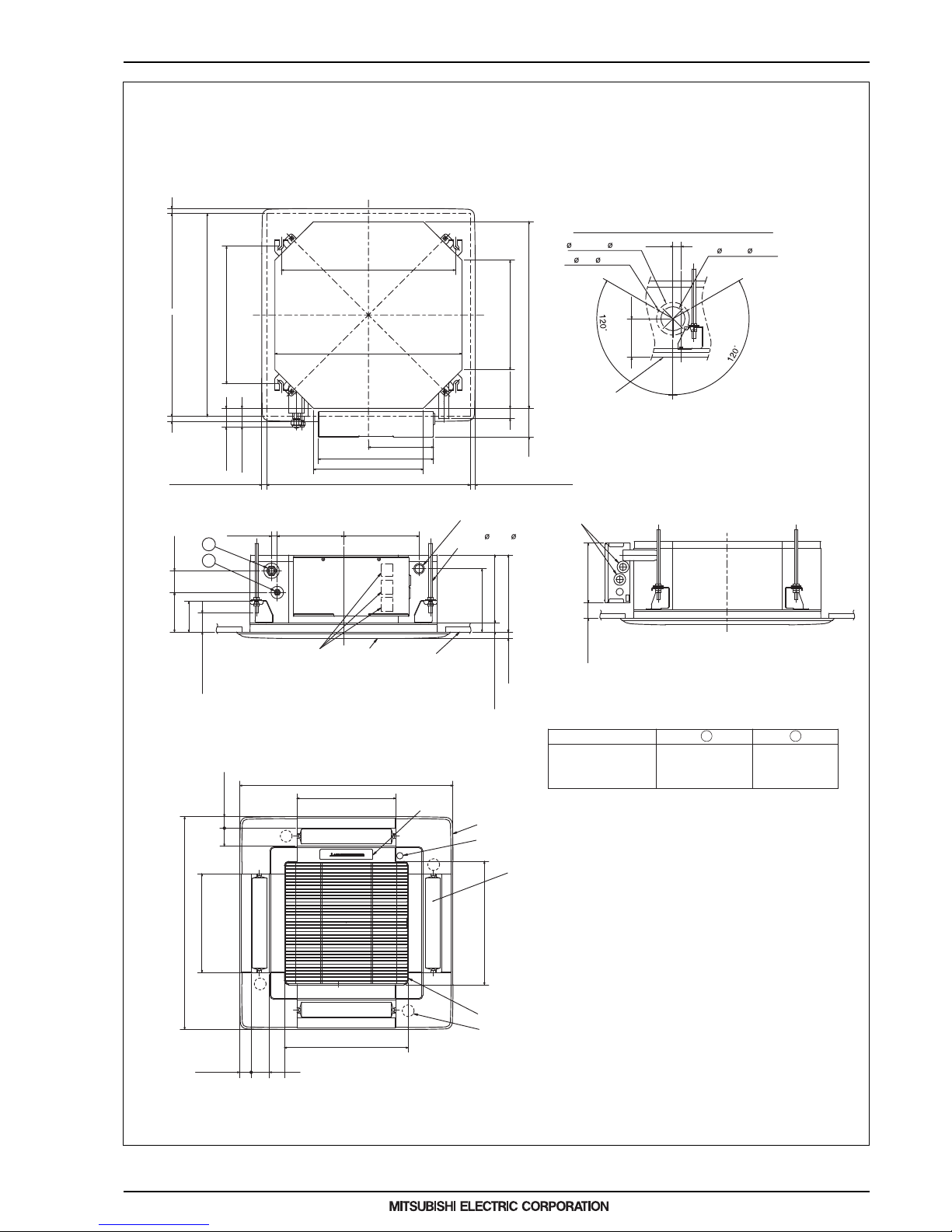
2. EXTERNAL DIMENSIONS
PLFY-P08, 12, 15 NCMU-E
PLFY-P15NCMU-E.TH
PLFY-P12NCMU-E.TH
PLFY-P08NCMU-E.TH
Brand label
(1/2 (12.7) dia.)
1/2
flared connection
Refrigerant pipe
flared connection
1/4
Refrigerant pipe
(1/4 (6.35) dia.)
V/M
V/M
V/M
V/M
1
Detail drawing of fresh air intake
Ceiling surface
Cut out hole
2-7/8( 73.4)
Burring hole
3- 1/8( 2.8)
3-15/16( 100)
4-21/32(118)
1(25)
Unit : in.(mm)
19/32~1-15/32(15~37) 19/32~1-15/32(15~37)
22-11/16~24-13/32(576~620)
22-7/16(570)
20-7/8(530)
1
2
2
Grille
Fresh air intake
Integrated lift pump outlet
VP-25 connection
(O.D. 1-1/4( 32))
Vane motor
Drain hole
Models
Air intake grille
2-5/32(55)
1-3/8(35)
1-3/8(35)
2-5/32(55)
Auto vane
Grille
Air intake hole
Air intake hole
Air outlet hole
Air outlet hole
11-27/32(301)
11-27/32(301)
14-27/32(377)
14-27/32(377)
25-19/32(650)
Suspension bolt M10 or W3/8
Suspension bolt lower edge
9-1/16(230)
7-5/32(182)1-7/8(48)
Wiring entry
Terminal block
Ceiling surface
9-1/4(235)
8-3/16(208)
7-19/32(193)
25/32(20)
3-21/32(93)
1-1/2~2-9/32(38~58)
2-19/32(66)
4-3/4(121)
7-15/16(202)
2-7/32(56)
2-1/14(57)
3-7/16(87)
1-7/32(31)
Ceiling hole
Suspension bolt pitch
19/32~1-15/32(15~37)
19/32~1-15/32(15~37)
22-11/16~24-13/32(576~620)
16-17/32(420)
22-7/16(570)
13-3/16(335)
7-27/32(199)
13-27/32(352)
13-3/16(335)
Suspension bolt pitch
Ceiling hole
25-19/32(650)
Unit : in.(mm)
1-1/16
+3/16
0
(
+5
)
0
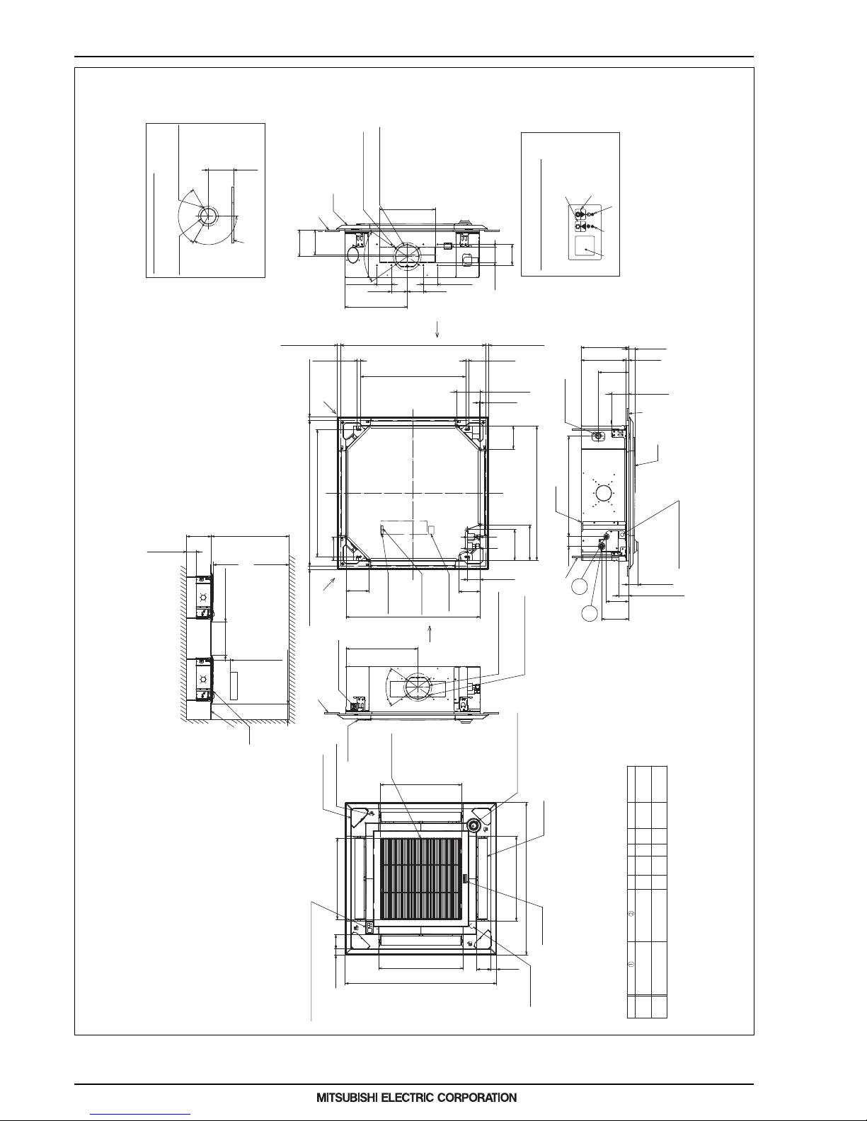
2. EXTERNAL DIMENSIONS
10
MEE16K008_U
12(305)
OR MORE
177-5/32(4500)
OR LESS
137-25/32(3500)
OR LESS
FE
10-7/16(265)
OR MORE
08~18
24~48
REFRIGERANT PIPEø6.35
FLARED CONNECTION 1/4F
REFRIGERANT PIPEø12.7
FLARED CONNECTION 1/2F
REFRIGERANT PIPEø9.52
FLARED CONNECTION 3/8F
REFRIGERANT PIPEø15.88
FLARED CONNECTION 5/8F
A
B
9-1/2
(241)
11-1/16
(281)
11-23/32
(298)
10-5/32
(258)
3(76)
3-1/8
(79.5)
C
3(76.5)
3-1/8
(79.5)
D
EP.NEMU
•
CAPACITY OF EACH MODEL AS FOLLOWING
PLFY-EP.NEMU-E*
:08/12/15/18/24/30/36/48
WALL
CEILING HEIGHT
SPACE TO THE
CEILING
GRILLE
FROM FLOOR
70-7/8(1800) OR MORE
INDOOR UNIT
INDOOR UNIT
FLOOR
BETWEEN INDOOR UNIT
OBSTRUCTION
CEILING
OR MORE
118-1/8(3000) OR MORE
59-1/16(1500) OR MORE
39-3/8(1000) OR MORE
9/32(7) OR MORE
E
FOR LESS
BETWEEN THE TOP OF
UNIT AND CEILING SLAB
NOTE1.PLEASE CHOOSE THE GRILLE FROM A STANDARD GRILLE, AUTO-GRILLE.
2.REINFORCE THE SUSPENSION BOLT BY EARTHQUAKE RESISTANCE SUPPORTING MATERIAL WHICH
USING FOR SWING PREVENTION IN ACCORDANCING WITH THE NECESSARY OF EARTHQUAKE
RESISTANCE ETC.SPECIALLY IN THE CASE WITHOUT CEILING MATERIAL, CONFIRM REINFORCING
3.AS FOR SUSPENSION BOLT, PLEASE USE M10 OR W3/8. (PROCURED AT LOCAL SITE)
4.AS FOR DRAIN PIPE, PLEASE USE VP-25(O.D. ø1-1/4"(ø32) PVC TUBE).
DRAIN PUMP INCLUSION. RAISE IS MAX 70-7/18"(850mm) FROM THE CEILING.
5.ELECTRICAL BOX MAY BE REMOVED FOR THE SERVICE PURPOSE.
MAKE SURE TO SLACK THE ELECTRICAL WIRE LITTLE BIT FOR
CONTROL/POWER WIRES CONNECTION.
6.THE HEIGHT OF THE INDOOR UNIT IS ABLE TO BE ADJUSTED
WITH THE GRILLE ATTACHED.
7.WHEN INSTALLING THE BRANCH DUCTS, BE SURE TO INSULATE ADEQUATELY.
OTHERWISE CONDENSATION AND DRIPPING MAY OCCUR.
(IT BECOMES THE CAUSE OF DEW DROPS/WEAR DEW.)
8.AS FOR NECESSARY INSTALLATION/SERVICE SPACE, PLEASE REFER TO THE RIGHT AT FIGURE.
9.OUTLINE DWG REFER TO EXCLUSIVE OUTLINE DWG WHEN INSTALL OPTION MULTIFUNCTION
CASEMENT AND OPTION HIGH PERFORMANCE FILTER
CEILING
ø3-15/16(ø100)
CUTTING OUT HOLE
ø4-29/32(ø125) BURRING HOLE PITCH
SELF-TAP 4 SCREWS:3 PLACES
DETAIL DRAWING OF FRESH AIR INTAKE HOLE
6-7/32
(158)
120 ˚
120 ˚
2
1
MAIN BODY
SUSPENSION BOLT M10
OR W3/8 SCREW
POWER SUPPLY WIRE ENTRY
GRILLE
DRAIN PIPE
CONNECT TO VP-25
CEILING
CONNECTING TO SOCKET OR
ATTACHED FLEXIBLE HOSE
(CONNECTING BY VINYL CHLORIDE
SERIES ADHESIVE)
THE BOTTOM OF
SUSPENSION BOLT
THE BOTTOM OF MOVE
EYE SENSOR
(17 )
+5
0
0
+3/16
2-9/32 (58)
1-31/32 TO 2-3/4
(50~70)
5-1/2
(140)
6-11/16
(170)
4-1/8 (105)
7-15/32
(190)
21/32
A
1-9/16 (40)
B
2-3/8
(60)
24-23/32(628)
GRILLE
CEILING
ø6-7/8(ø175) BURRING HOLE PITCH
SELF-TAP 4 SCREWS:4 PLACES
(BRANCH DUCT HOLE)
ø5-29/32(ø150) CUTTING OUT HOLE
(BRANCH DUCT HOLE)
6-9/16
(167)
6-3/32
(155)
15-11/32(390)
3-17/32
(90)
3-15/16
(100)
3-15/16
(100)
3-17/32
(90)
13-25/32(350)
5-1/8
(130)
3-15/16
(100)
70 ˚
(CEILING HOLE)
(SUSPENSION BOLT PITCH)
(SUSPENSION BOLT PITCH)
(CEILING HOLE)
FRESH AIR
INTAKE HOLE
BRANCH DUCT
HOLE
REMOTE CONTROLLER
WIRE ENTRY
POWER SUPPLY
TERMINAL BLOCK
INDOOR UNIT
/OUTDOOR UNIT
CONNECTING
TERMINAL BED
(BOARD PACKAGING)
BRANCH DUCT
HOLE
HUMIDIFIER HOLE
+40
0
0
+1-9/16
(660 )
TERMINAL BED
FOR REMOTE
CONTROLLER
(BOARD PACKAGING)
25/32 TO 1-25/32
(20~45)
33-27/32 TO 35-13/16(860~910)
(25/32 )
(20)
26
25/32 TO 1-25/32
(20~45)
25/32 TO 1-25/32
(20~45)
25/32 TO 1-25/32
(20~45)
31-5/16 (795)
31-7/8 TO 35-13/16(810~910)
33-1/16(840)
33-1/16(840)
5-23/32
(145)
5-5/8
(145)
1/4(6)
5-23/32
(145)
5-23/32(145)
(25/32 )
(20)
8-3/4
(222)
7-19/32
(193)
3-1/8(79.5)
5-1/8
(133)
D
C
REMOTE CONTROLLER
WIRE ENTRY
GRILLE
ø5-29/32(ø150) CUTTING OUT HOLE
(CONNECTING TO BRANCH DUCT)
ø6-7/8(ø175) BURRING HOLE PITCH
SELF-TAP 4 SCREWS
:4 PLACES
(CONNECTING TO BRANCH DUCT)
CEILING
17-23/32(450)
70
˚
VANE MOTOR(1 PCS/CONNER)
COMPANY NAME
DISPLAY PART
*IN CASE OF STANDARD PANEL
WITHOUT RADIATION SENSOR
*CAN INSTALL TO THE CONNER
EXCEPT DRAIN PIPE CORNER
(BUT NEED TO SELECT FUNCTION
BY REMOTE CONTROLLER)
IN CASE OF MOVE EYE
SENSOR PANEL
RADIATION SENSOR(MOVE EYE
SENSOR) STANDARD INSTALLATION
POSITION
AIR INTAKE GRILLE
(AIR INTAKE HOLE)
EASY CORNER POCKET
DRAIN PUNCH HOLE
AUTOVANE(AIR
OUTLET HOLE)
(AIR OUTLET HOLE)
(AIR OUTLET HOLE)
(AIR INTAKE HOLE)
(AIR INTAKE HOLE)
OPTION WIRELESS RECEIVING PART KIT
RECEIVING PART STANDARD INSTALLATION POSITION
*NONE IN THE CASE OF STANDARD PANEL
20-7/8(530)
20-7/8(530)
37-13/32(950)
37-13/32(950)
20(508)
20(508)
3-1/2
(89)
1-15/32(37)
3-1/2
(89)
1-15/32
(37)
DEFROST/STAND BY LAMP
OPERATION
LAMP
RECEIVING
PART
EMERGENCY OPERATION
SWITCH <HEATING> AND
EMERGENCY UP/DOWN
SWITCH<DOWN>
EMERGENCY OPERATION
SWITCH <COOLING> AND
EMERGENCY UP/DOWN
SWITCH<UP>
IN CASE OF OPTION WIRELESS RECEIVING PART KIT
RECEIVING PART
PLFY-EP08, 12, 15, 18, 24, 30, 36, 48 NEMU-E
Unit : in.(mm)
 Loading...