

Mitsubishi PLA-ZM-EA Operation Manual

Packaged Air Conditioners
Indoor unit
PLA-ZM.EA Series
OPERATION MANUAL
For safe and correct use, please read this operation manual thoroughly before operating the air-conditioner unit.
BEDIENUNGSHANDBUCH
Zum sicheren und einwandfreien Gebrauch der Klimaanlage dieses Bedienungshandbuch vor Inbetriebnahme
gründlich durchlesen.
MANUEL D’UTILISATION
Pour une utilisation correcte sans risques, veuillez lire le manuel d’utilisation en entier avant de vous servir du
climatiseur.
BEDIENINGSHANDLEIDING
Voor een veilig en juist gebruik moet u deze bedieningshandleiding grondig doorlezen voordat u de airconditioner
gebruikt.
MANUAL DE INSTRUCCIONES
Lea este manual de instrucciones hasta el nal antes de poner en marcha la unidad de aire acondicionado para
garantizar un uso seguro y correcto.
ISTRUZIONI DI FUNZIONAMENTO
Leggere attentamente questi istruzioni di funzionamento prima di avviare l’unità, per un uso corretto e sicuro della
stessa.
ΕΓΧΕΙΡΙΔΙΟ ΟΔΗΓΙΩΝ ΧΡΗΣΕΩΣ
Για ασφάλεια και σωστή χρήση, παρακαλείστε διαβάσετε προσεχτικά αυτό το εγχειρίδιο χρήσεως πριν θέσετε σε
λειτουργία τη μονάδα κλιματισμού.
MANUAL DE OPERAÇÃO
Para segurança e utilização correctas, leia atentamente o manual de operação antes de pôr a funcionar a unidade de ar condicionado.
FOR USER
FÜR BENUTZER
POUR L’UTILISATEUR
VOOR DE GEBRUIKER
PARA EL USUARIO
PER L’UTENTE
ΓΙΑ ΤΟΝ ΧΡΗΣΤΗ
PARA O UTILIZADOR
English
Deutsch
Français
Nederlands
Español
Italiano
Ελληνικά
Português
DRIFTSMANUAL
Læs venligst denne driftsmanual grundigt før airconditionanlægget betjenes af hensyn til sikker og korrekt brug.
DRIFTSMANUAL
Läs denna driftsmanual noga för säkert och korrekt bruk innan luftkonditioneringen används.
Işletme Elkitabı
Emniyetli ve doğru biçimde nasıl kullanılacağını öğrenmek için lütfen klima cihazını işletmeden önce bu elkitabını
dikkatle okuyunuz.
BRUKSANVISNING
Vennligst les nøye gjennom denne bruksanvisningen, for sikkert og riktig bruk av klimaanlegget.
INSTRUKCJA OBSŁUGI
Aby zapewnić bezpieczne i prawidłowe korzystanie z urządzenia, należy wcześniej uważnie przeczytać niniejszą
instrukcję obsługi.
TIL BRUGER
Dansk
FÖR ANVÄNDAREN
Svenska
KULLANICI İÇİN
Türkçe
FOR BRUKER
Norsk
INFORMACJA DLA UŻYTKOWNIKA
Polski
Contents
1. Safety Precautions .......................................2
2. Parts Names ............................................3
3. Operation ..............................................7
4. Timer .................................................13
This symbol mark is for EU countries only.
Note
Fig.1
Note:
The phrase “Wired remote controller” in this operation manual refers only to the PAR-32MAA. If you need any information for the other remote
controller, please refer to the instruction book included in this box.
This symbol mark is according to the directive 2012/19/EU Article 14 Information for users and Annex IX, and/or to the directive
2006/66/EC Article 20 Information for end-users and Annex II.
Your MITSUBISHI ELECTRIC product is designed and manufactured with high quality materials and components which can be recycled and/
or reused. This symbol means that electrical and electronic equipment, batteries and accumulators, at their end-of-life, should be disposed
of separately from your household waste. If a chemical symbol is printed beneath the symbol (Fig. 1), this chemical symbol means that the
battery or accumulator contains a heavy metal at a certain concentration.
This will be indicated as follows: Hg: mercury (0.0005%), Cd: cadmium (0.002%), Pb: lead (0.004%)
In the European Union there are separate collection systems for used electrical and electronic products, batteries and accumulators.
Please, dispose of this equipment, batteries and accumulators correctly at your local community waste collection/recycling centre.
Please, help us to conserve the environment we live in!
5. Emergency Operation for Wireless Remote-controller ...........14
6. Care and Cleaning. . . . . . . . . . . . . . . . . . . . . . . . . . . . . . . . . . . . . . . 14
7. Trouble Shooting ........................................15
8. Specications ..........................................17
1. Safety Precautions
► Before installing the unit, make sure you read all the “Safety Precautions”.
► The “Safety Precautions” provide very important points regarding safety. Make sure you follow them.
► Please report to or take consent by the supply authority before connection to the system.
MEANINGS OF SYMBOLS DISPLAYED ON THE UNIT
WARNING
(Risk of re)
This mark is for R32 refrigerant only. Refrigerant type is written on nameplate of outdoor unit.
In case that refrigerant type is R32, this unit uses a ammable refrigerant.
If refrigerant leaks and comes in contact with re or heating part, it will create harmful gas and there is risk of re.
Read the OPERATION MANUAL carefully before operation.
Service personnel are required to carefully read the OPERATION MANUAL and INSTALLATION MANUAL before operation.
Further information is available in the OPERATION MANUAL, INSTALLATION MANUAL, and the like.
Symbols used in the text
Warning:
Describes precautions that should be observed to prevent danger of in-
jury or death to the user.
Caution:
Describes precautions that should be observed to prevent damage to
the unit.
Warning:
• There appliances are not accessible to the general public.
• The unit must not be installed by the user. Ask the dealer or an authorized company to install the unit. If the unit is installed improperly,
water leakage, electric shock or re may result.
• Do not stand on, or place any items on the unit.
• Do not splash water over the unit and do not touch the unit with wet
hands. An electric shock may result.
• Do not spray combustible gas close to the unit. Fire may result.
• Do not place a gas heater or any other open-ame appliance where it
will be exposed to the air discharged from the unit. Incomplete combustion may result.
• Do not remove the front panel or the fan guard from the outdoor unit
when it is running.
• When you notice exceptionally abnormal noise or vibration, stop operation, turn off the power switch, and contact your dealer.
• Never insert ngers, sticks etc. into the intakes or outlets.
• If you detect odd smells, stop using the unit, turn off the power switch
and consult your dealer. Otherwise, a breakdown, electric shock or re
may result.
• This air conditioner is NOT intended for use by children or inrm persons without supervision.
• Young children must be supervised to ensure that they do not play
with the air conditioner.
• If the refrigeration gas blows out or leaks, stop the operation of the air
conditioner, thoroughly ventilate the room, and contact your dealer.
•
This appliance is intended to be used by expert or trained users in shops,
in light industry and on farms, or for commercial use by lay persons.
Symbols used in the illustrations
: Indicates a part which must be grounded.
• This appliance can be used by children aged from 8 years and above
and persons with reduced physical, sensory or mental capabilities or
lack of experience and knowledge if they have been given supervision
or instruction concerning use of the appliance in a safe way and understand the hazards involved. Children shall not play with the appliance.
Cleaning and user maintenance shall not be made by children without
supervision.
• This appliance is not intended for use by persons (including children)
with reduced physical, sensory or mental capabilities, or lack of experience and knowledge, unless they have been given supervision or
instruction concerning use of the appliance by a person responsible
for their safety.
• Children should be supervised to ensure that they do not play with the
appliances.
• When installing or relocating, or servicing the air conditioner, use only
the specied refrigerant written on outdoor unit to charge the refrigerant lines. Do not mix it with any other refrigerant and do not allow air
to remain in the lines.
If air is mixed with the refrigerant, then it can be the cause of abnormal
high pressure in the refrigerant line, and may result in an explosion
and other hazards.
The use of any refrigerant other than that specied for the system will
cause mechanical failure or system malfunction or unit breakdown. In
the worst case, this could lead to a serious impediment to securing
product safety.
• This unit should be installed in rooms which exceed the oor space
specied in outdoor unit installation manual.
Refer to outdoor unit installation manual.
2
1. Safety Precautions
• Do not use means to accelerate the defrosting process or to clean,
other than those recommended by the manufacturer.
• The appliance shall be stored in a room without continuously operating ignition sources (for example: open ames, an operating gas appliance or an operating electric heater).
Caution:
• Do not use any sharp object to push the buttons, as this may damage
the remote controller.
•
Never block or cover the indoor or outdoor unit’s intakes or outlets.
2. Parts Names
■
Indoor Unit
PLA-ZM·EA
Fan steps 4 steps
Vane Auto with swing
Louver –
Filter Long-life
Filter cleaning indication 2,500 hr
Wireless remote controller model No.
setting
■
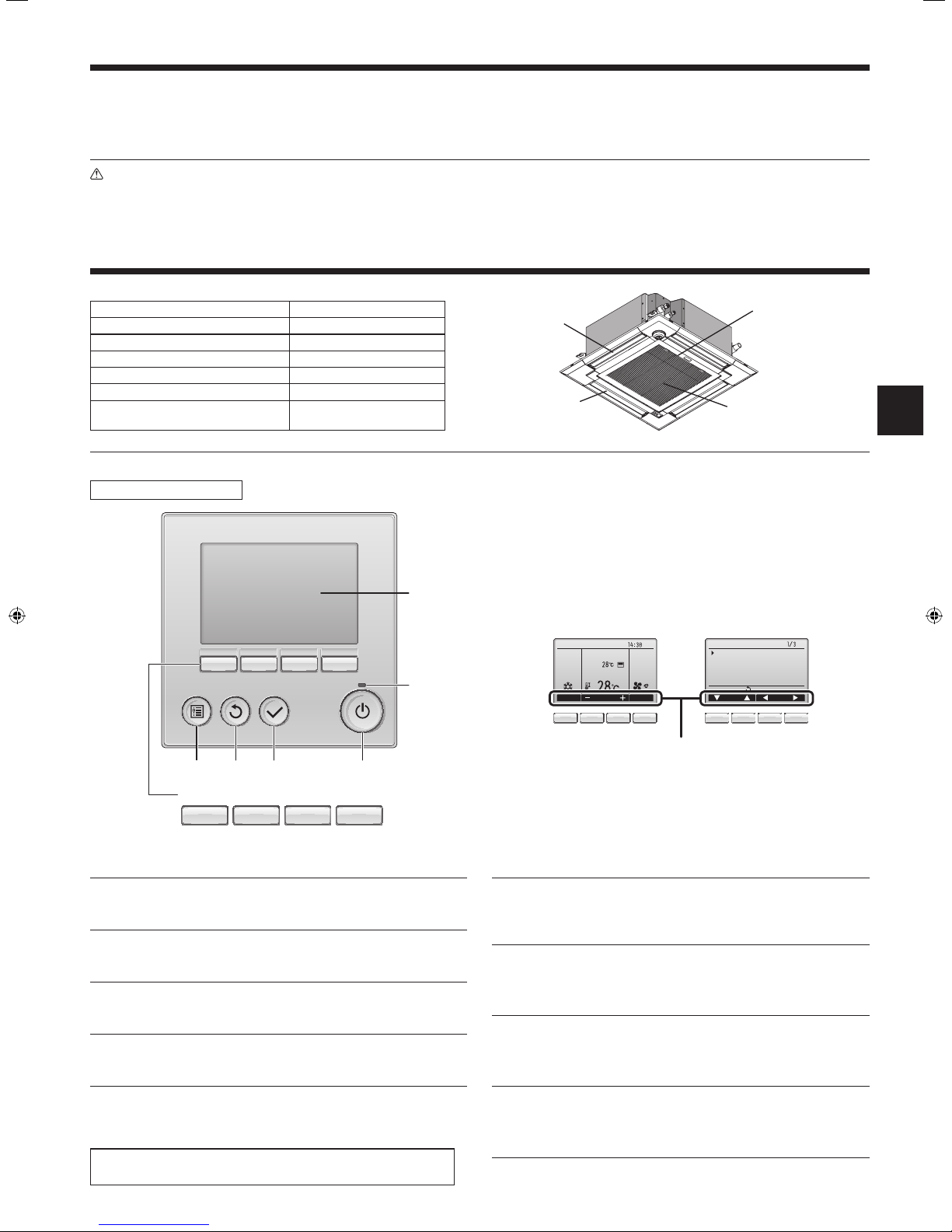
Wired Remote Controller
Controller interface
001
5
• Do not pierce or burn.
• Be aware that refrigerants may not contain an odour.
Disposing of the unit
When you need to dispose of the unit, consult your dealer.
Air outlet
Vane
The functions of the function buttons change depending on the
screen.
Refer to the button function guide that appears at the bottom of the
LCD for the functions they serve on a given screen.
When the system is centrally controlled, the button function guide
that corresponds to the locked button will not appear.
Filter
Air intake
4 3 2 1
Function buttons
7 8 9 0
▌1 [ON/OFF] button
Press to turn ON/OFF the indoor unit.
▌2 [SELECT] button
Press to save the setting.
▌3 [RETURN] button
Press to return to the previous screen.
▌4 [MENU] button
Press to bring up the Main menu.
▌5 Backlit LCD
Operation settings will appear.
When the backlight is off, pressing any button turns the backlight on
and it will stay lit for a certain period of time depending on the screen.
When the backlight is off, pressing any button turns the backlight on
and does not perform its function. (except for the [ON/OFF] button)
Main display Main menu
Room
Set temp.
6
Cool Auto
Mode Temp. Fan
Fri
Main
Main menu
Vane·Louver·Vent. (Lossnay)
High power
Timer
Weekly timer
OU silent mode
Main display:
Cursor Page
7 8 9 0 7 8 9 0
Function guide
▌6 ON/OFF lamp
This lamp lights up in green while the unit is in operation. It blinks while
the remote controller is starting up or when there is an error.
▌7 Function button [F1]
Main display: Press to change the operation mode.
Main menu: Press to move the cursor down.
▌8 Function button [F2]
Main display: Press to decrease temperature.
Main menu: Press to move the cursor up.
▌9 Function button [F3]
Main display: Press to increase temperature.
Main menu: Press to go to the previous page.
▌0 Function button [F4]
Main display: Press to change the fan speed.
Main menu: Press to go to the next page.
3
2. Parts Names
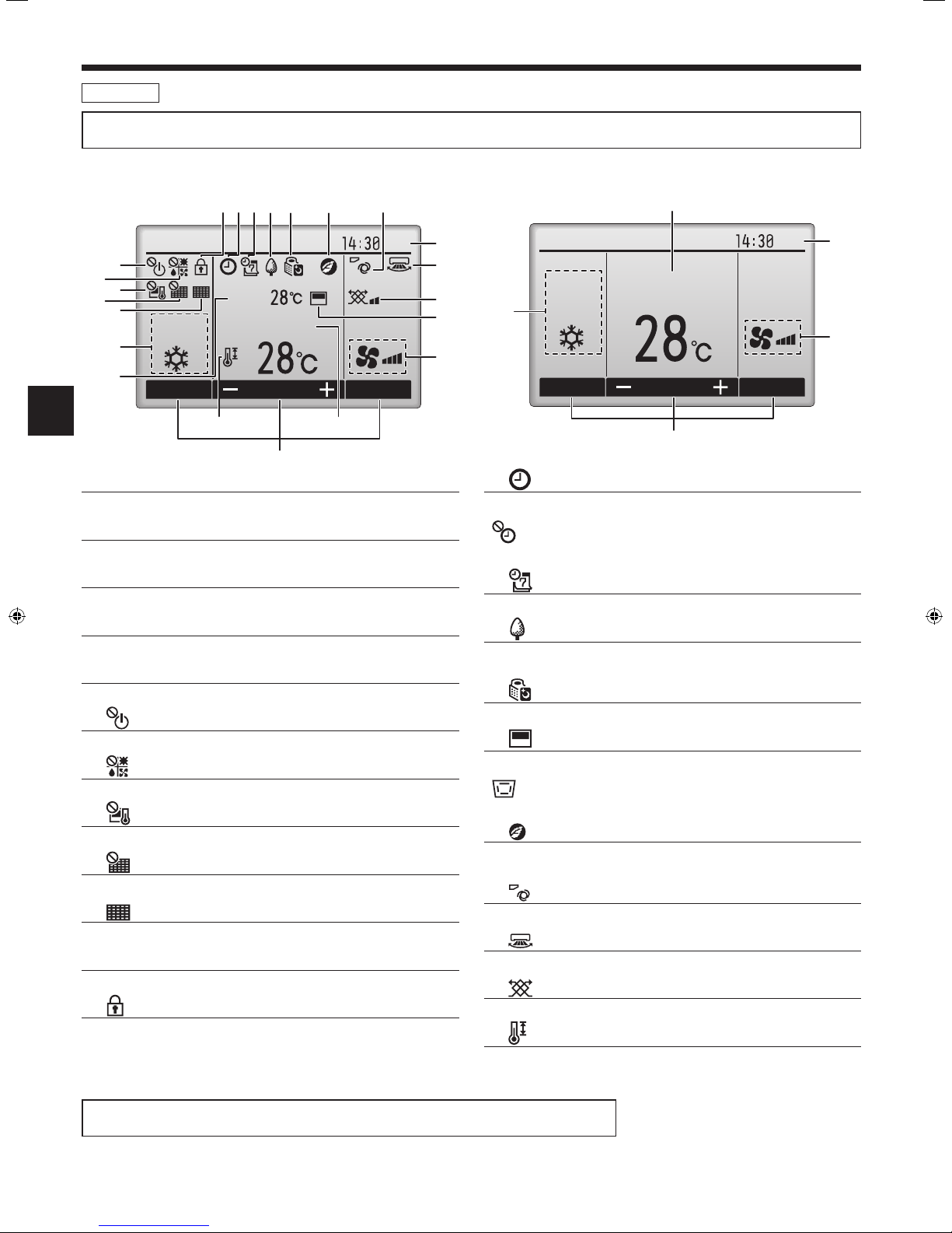
Display
The main display can be displayed in two different modes: “Full” and “Basic”. The factory setting is “Full”. To switch to the “Basic” mode, change the
setting on the Main display setting. (Refer to operation manual included with remote controller.)
<Full mode>
* All icons are displayed for explanation.
2 3 4 5 6 8 9
Fri
6
7
8
9
0
Cool
Room
Set temp.
1
1
Mode Temp. Fan
@
5
▌1 Operation mode
Indoor unit operation mode appears here.
▌2 Preset temperature
Preset temperature appears here.
▌3 Clock (See the Installation Manual.)
Current time appears here.
▌4 Fan speed
Fan speed setting appears here.
▌5 Button function guide
Functions of the corresponding buttons appear here.
▌6
Appears when the ON/OFF operation is centrally controlled.
▌7
Appears when the operation mode is centrally controlled.
▌8
Appears when the preset temperature is centrally controlled.
▌9
Appears when the lter reset function is centrally controlled.
▌0
Indicates when lter needs maintenance.
▌1 Room temperature (See the Installation Manual.)
Current room temperature appears here.
▌2
Appears when the buttons are locked.
2
<Basic mode>
2
3
Fri
3
)
!
7
1
Cool
Set temp.
4
4
Mode Temp. Fan
5
▌3
Appears when the On/Off timer, Night setback, or Auto-off timer function is enabled.
appears when the timer is disabled by the centralized control
system.
▌4
Appears when the Weekly timer is enabled.
▌5
Appears while the units are operated in the energy-save mode. (Will
not appear on some models of indoor units)
▌6
Appears while the outdoor units are operated in the silent mode.
▌7
Appears when the built-in thermistor on the remote controller is activated to monitor the room temperature (1).
appears when the thermistor on the indoor unit is activated to
monitor the room temperature.
▌8
Appears when the units are operated in the energy-save mode with 3D
i-see Sensor.
▌9
Indicates the vane setting.
▌)
Indicates the louver setting.
▌!
Indicates the ventilation setting.
▌@
Appears when the preset temperature range is restricted.
Most settings (except ON/OFF, mode, fan speed, temperature) can be made from the Menu screen.
(Refer to operation manual included with remote controller.)
4
2. Parts Names
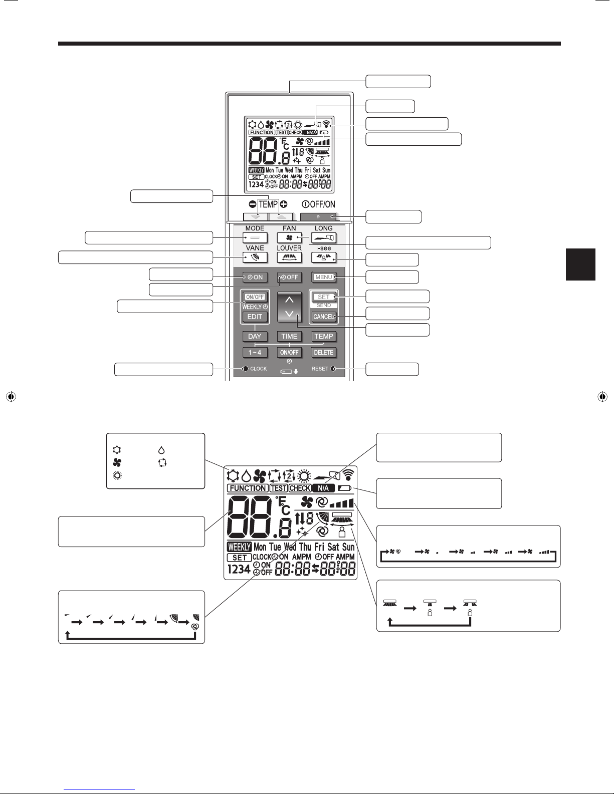
■ Wireless Remote-Controller
Set Temperature buttons
Transmission area
Not available
Remote controller display
Battery replacement indicator
OFF/ON button
Mode button (Changes operation mode)
Air ow button (Changes up/down air ow direction)
Timer ON button
Timer OFF button
Weekly timer ON/OFF button
Set Time button (Sets the time)
Operation mode
Cool Dry
Fan Auto
Heat
Temperature setting
The units of temperature can be changed. For
details, refer to the Installation Manual.
Fan Speed button (Changes fan speed)
i-see button
Menu button
SET/SEND button
CANCEL button
Up/Down buttons
Reset button
Not available
Appears when a non-supported function is selected.
Battery replacement indicator
Appears when the remaining battery
power is low.
Fan speed setting
Auto
Vane setting
Step 1 Step 2 Step 3 Step 4 Step 5 Swing Auto
3D i-see Sensor (Air distribution)
Default Direct Indirect
When Direct or Indirect
is selected, the vane
setting is set to “Auto”.
5
2. Parts Names
Notes (Only for wireless remote controller):
■ When using the wireless remote controller, point it towards the receiver on the indoor unit.
■ If the remote controller is operated within approximately 2 minutes after power is supplied to the
indoor unit, the indoor unit may beep twice as the unit is performing the initial automatic check.
■ The indoor unit beeps to conrm that the signal transmitted from the remote controller has been
received. Signals can be received up to approximately 7 meters in a direct line from the indoor
unit in an area 45° to the left and right of the unit. However, illumination such as uorescent lights
and strong light can affect the ability of the indoor unit to receive signals.
■ If the operation lamp near the receiver on the indoor unit is blinking, the unit needs to be inspected.
Consult your dealer for service.
■ Handle the remote controller carefully! Do not drop the remote controller or subject it to strong
shocks. In addition, do not get the remote controller wet or leave it in a location with high humidity.
■ To avoid misplacing the remote controller, install the holder included with the remote controller on
a wall and be sure to always place the remote controller in the holder after use.
■ If the indoor unit beeps 4 times when you are using the wireless remote controller, switch the auto
mode setting to the AUTO (single set point) mode or AUTO (dual set point) mode.
For details, refer to the included Notice (A5 sheet) or the Installation Manual of wireless remote
controller.
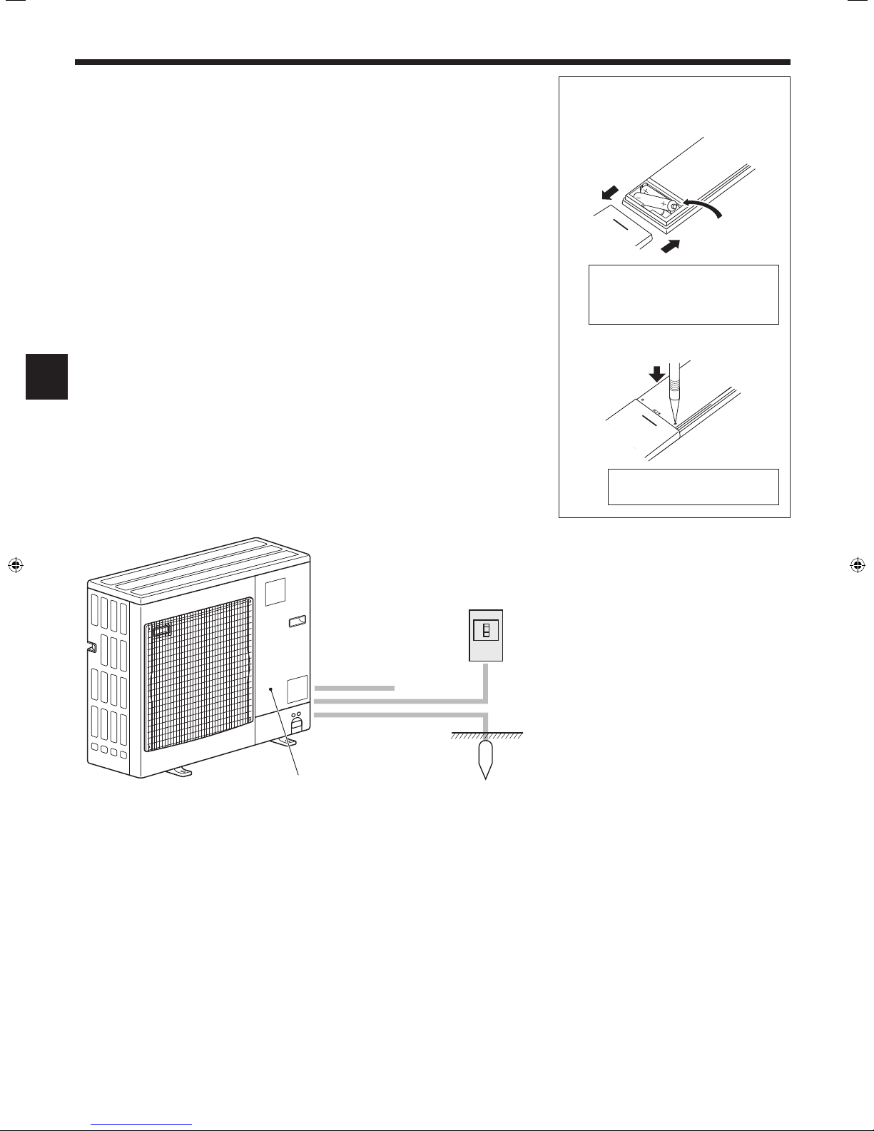
Battery installation/replacement
1. Remove the top cover, insert two LR6 AA
batteries, and then install the top cover.
1
2
Top cover
3
Two LR6 AA batteries
Insert the negative (–) end of each
battery rst. Install the batteries in the
correct directions (+, –)!
2. Press the Reset button.
Press the Reset button with an
object that has a narrow end.
■
Outdoor unit
Power
Ref. Pipes
Indoor-Outdoor
Connection wire
Earth
Service Panel
6
 Loading...