

Mitsubishi Electric PLA-SP71BA.UK, PLA-SP100BA.UK, PLA-SP125BA.UK, PLA-SP140BA.UK, PLA Service Manual
SERVICE MANUAL
SPLIT-TYPE, HEAT PUMP AIR CONDITIONERS
SPLIT-TYPE, AIR CONDITIONERS
Note:
• This manual describes service
data of the indoor units only.
• RoHS compliant products
have <G> mark on the spec
name plate.
CONTENTS
1. REFERENCE MANUAL
..................................
2
2. SAFETY PRECAUTION
..................................
3
3. PARTS NAMES AND FUNCTIONS
................
4
4. SPECIFICATIONS
.........................................
11
5. NOISE CRITERION CURVES
.......................
13
6. OUTLINES AND DIMENSIONS
.....................
14
7. WIRING DIAGRAM
........................................
15
8. REFRIGERANT SYSTEM DIAGRAM
...........
16
9. TROUBLESHOOTING
...................................
17
10. SPECIAL FUNCTION
....................................
33
11. DISASSEMBLY PROCEDURE
......................
41
WIRED REMOTE
CONTROLLER
WIRELESS REMOTE
CONTROLLER
ON/OFF TEMP
INDOOR UNIT
Model name
indication
PARTS CATALOG (OCB565)
No. OCH565
May 2014
Indoor unit
[Model Name]
PLA-SP71BA
PLA-SP100BA
PLA-SP125BA
PLA-SP140BA
[Service Ref.]
PLA-SP71BA.UK
PLA-SP100BA.UK
PLA-SP125BA.UK
PLA-SP140BA.UK

2
1
REFERENCE MANUAL
OUTDOOR UNIT’S SERVICE MANUAL
Service Ref Service Manual No.
SUZ-SA71VA.TH
OCH561
OCB561
PUHZ-SP100/120/140V(Y)HA
OCH566
OCB566
OCH565
3
SAFETY PRECAUTION
2
Cautions for units utilising refrigerant R410A
2-2. CAUTIONS RELATED TO NEW REFRIGERANT
Use new refrigerant pipes.
Store the piping indoors, and both ends of the
piping sealed until just before brazing.
(Leave elbow joints, etc. in their packaging.)
In case of using the existing pipes for R22, be careful with
the followings.
· For RP100, 125 and 140, be sure to perform replace ment operation before test run.
· Change flare nut to the one provided with this product.
Use a newly flared pipe.
· Avoid using thin pipes.
Charge refrigerant from liquid phase of gas
cylinder.
If the refrigerant is charged from gas phase, composition
change may occur in refrigerant and the efficiency will be
lowered.
Do not use refrigerant other than R410A.
If other refrigerant (R22 etc.) is used, chlorine in refrigerant can cause deterioration of refrigerant oil etc.
Use a vacuum pump with a reverse flow check
valve.
Vacuum pump oil may flow back into refrigerant cycle and
that can cause deterioration of refrigerant oil etc.
Use the following tools specifically designed for
use with R410A refrigerant.
The following tools are necessary to use R410A refrigerant.
Handle tools with care.
If dirt, dust or moisture enters into refrigerant cycle, that can
cause deterioration of refrigerant oil or malfunction of compressor.
Do not use a charging cylinder.
If a charging cylinder is used, the composition of refrigerant will change and the efficiency will be lowered.
Flare tool
Electronic refrigerant
charging scale
Vacuum pump adaptor
Size adjustment gauge
Gauge manifold
Torque wrench
Gas leak detector
Charge hose
Tools for R410A
Contamination inside refrigerant piping can cause deterioration of refrigerant oil etc.
If dirt, dust or moisture enters into refrigerant cycle, that can
cause deterioration of refrigerant oil or malfunction of compressor.
If large amount of mineral oil enters, that can cause deterioration of refrigerant oil etc.
Ventilate the room if refrigerant leaks during
operation. If refrigerant comes into contact with
a flame, poisonous gases will be released.
Never use any refrigerant other than that specified.
Doing so may cause a burst, an explosion, or fire when the
unit is being used, serviced, or disposed of.
Correct refrigerant is specified in the manuals and on the
spec labels provided with our products.
We will not be held responsible for mechanical failure,
system malfunction, unit breakdown or accidents caused
by failure to follow the instructions.
Use the specified refrigerant only.
Make sure that the inside and outside of refrigerant piping is clean and it has no contaminants
such as sulfur, oxides, dirt, shaving particles, etc,
which are hazard to refrigerant cycle.
In addition, use pipes with specified thickness.
The refrigerant oil applied to flare and flange
connections must be ester oil, ether oil or
alkylbenzene oil in a small amount.
[1] Cautions for service
(1) Perform service after recovering the refrigerant left in unit completely.
(2) Do not release refrigerant in the air.
(3) After completing service, charge the cycle with specified amount of refrigerant.
(4) When performing service, install a filter drier simultaneously.
Be sure to use a filter drier for new refrigerant.
2-1. ALWAYS OBSERVE FOR SAFETY
Before obtaining access to terminal, all supply
circuits must be disconnected.
OCH565
4
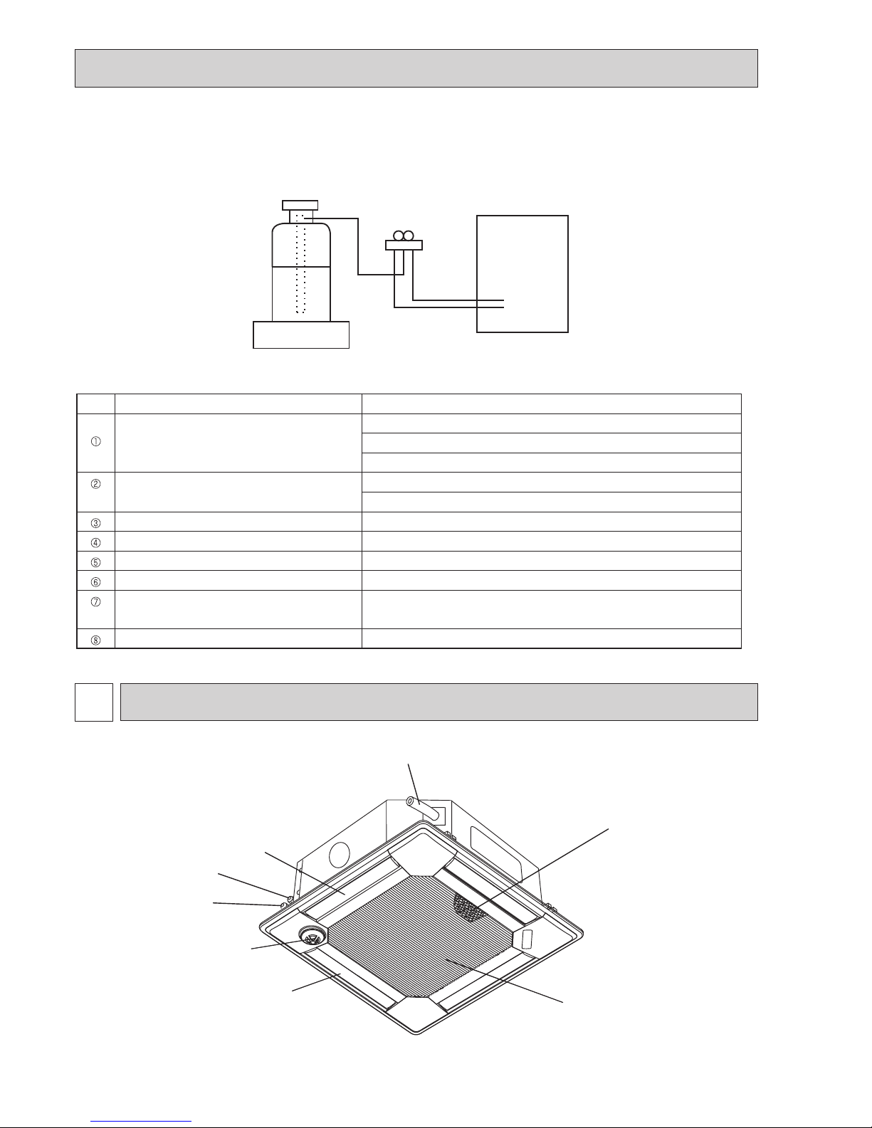
[3] Service tools
Use the below service tools as exclusive tools for R410A refrigerant.
3
PARTS NAMES AND FUNCTIONS
Drain pipe
Filter
Vane
Gas pipe
Liquid pipe
Air outlet
i-see sensor
(option)
Air intake
(Intake grille)
Gravimeter
Unit
[2] Additional refrigerant charge
When charging directly from cylinder
· Check that cylinder for R410A on the market is syphon type.
· Charging should be performed with the cylinder of syphon stood vertically. (Refrigerant is charged from liquid phase.)
No.
Tool name Specifications
Gauge manifold · Only for R410A
· Use the existing fitting
specifications
. (UNF1/2)
· Use high-tension side pressure of 5.3MPa·G or over.
Charge hose · Only for R410A
· Use pressure performance of 5.09MPa·G or over.
Electronic scale
—
Gas leak detector · Use the detector for R410A.
Adaptor for reverse flow check · Attach on vacuum pump.
Refrigerant charge base
—
Refrigerant cylinder · Only for R410A · Top of cylinder (Pink)
· Cylinder with syphon
Refrigerant recovery equipment
—
3-1. INDOOR UNIT
OCH565
5
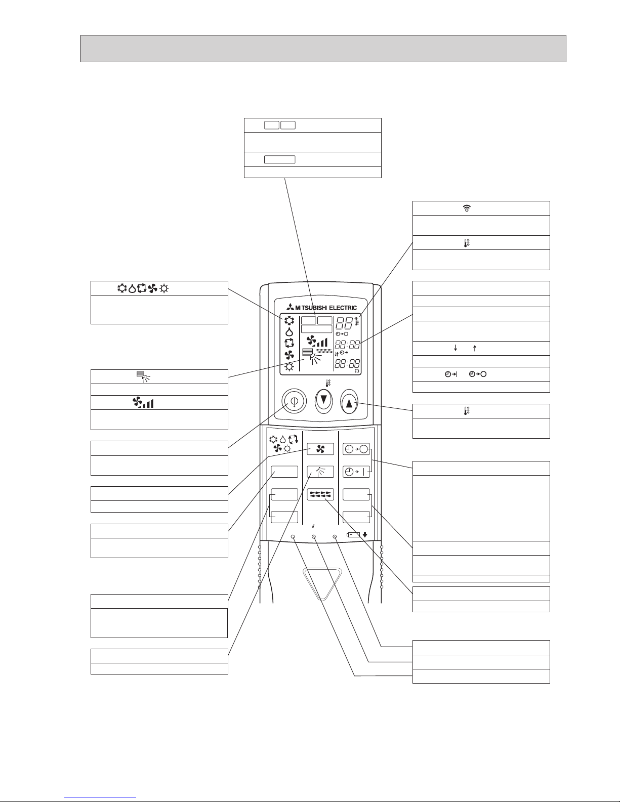
ON/OFF TEMP
FAN
VANE
TEST RUN
AUTO STOP
AUTO START
h
min
LOUVER
MODE
CHECK
RESETSET CLOCK
MODEL SELECT
NOT AVAILABLE
CHECK
TEST RUN
°C
AMPM
AMPM
VANE CONTROL button
Used to change the air flow direction.
CLOCK button
RESET button
SET button
ON/OFF button
The unit is turned ON and OFF alternately
each time
the button is pressed.
MODE SELECT button
Used to switch the operation mode between
cooling, drying, heating, auto and fan mode.
CHECK-TEST RUN button
Only press this button to perform an
inspection check or test operation.
Do not use it for normal operation.
FAN SPEED SELECT button
Used to change the fan speed.
TIMER display
Displays when in timer operation or when
setting timer.
button
SET TEMPERATURE button sets any desired
room temperature.
CLOCK display
Displays the current time.
“ ” “ ” display
Displays the order of timer operation.
“ ” “ ” display
Displays whether timer is on or off.
Buttons used to set the “hour and minute” of
the current time and timer settings.
h and min buttons
display
display
FAN SPEED display indicates which fan
speed has been selected.
display
The vertical direction of air flow is indicated.
display
Blinks when model is selected.
display
display
CHECK and TEST RUN display indicate that
the unit is being checked or test-run.
display
OPERATION MODE display
Operation mode display indicates which
operation mode is in effect.
AUTO STOP (OFF timer): when this switch
is set, the air conditioner will be
automatically stopped at the preset time.
AUTO START (ON timer): when this switch is
set, the air conditioner will be automatically
started at the preset time.
MODEL SELECT
CHECK
TEST RUN
LOUVER button
Changes left/right airflow direction.
(Not available for this model.)
SET TEMP. display indicates the desired
temperature which is set.
Lights up while the signal is transmitted to
the indoor unit when the button is pressed.
TIMER CONTROL buttons
3-2. WIRELESS REMOTE CONTROLLER
OCH565
6
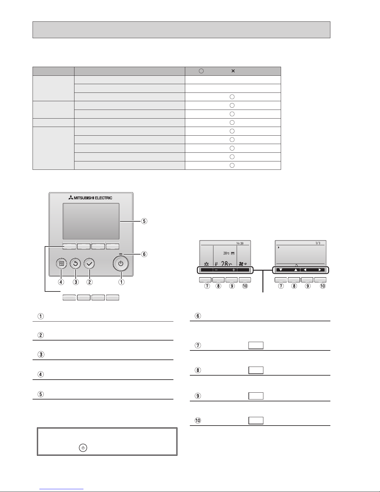
Function buttons
F1 F2 F3 F4
Press to turn ON/OFF the indoor unit.
ON / OFF button
When the backlight is off, pressing any button turns
the backlight on and does not perform its function.
(except for the
(ON / OFF) button)
The functions of the function buttons change depending on
the screen. Refer to the button function guide that appears
at the bottom of the LCD for the functions they serve on a
given screen.
When the system is centrally controlled, the button function
guide that corresponds to the locked button will not appear.
Press to save the setting.
SELECT button
Press to return to the previous screen.
RETURN button
Press to bring up the Main menu.
MENU button
Operation settings will appear.
When the backlight is off, pressing any button turns the
backlight on and it will stay lit for a certain period of time
depending on the screen.
Backlit LCD
This lamp lights up in green while the unit is in operation.
It blinks while the remote controller is starting up or when
there is an error.
ON / OFF lamp
Main display : Press to change the operation mode.
Main menu : Press to move the cursor down.
Function button
F1
Main display : Press to decrease temperature.
Main menu : Press to move the cursor up.
Function button
F2
Main display : Press to increase temperature.
Main menu : Press to go to the previous page.
Function button
F3
Main display : Press to change the fan speed.
Main menu : Press to go to the next page.
Function button
F4
Fri
Room
Set temp.
Mode Temp. Fan
Cool Auto
Main
Main display:
Cursor Page
Main menu
Vane·Louver·Vent. (Lossnay)
High power
Timer
Weekly timer
OU silent mode
<Main display> <Main menu>
Function guide
3-3. WIRED REMOTE CONTROLLER <PAR-31MAA>
Function
: Supported : Unsupported
Body Product size H × W × D (mm) 120 × 120 × 19
LCD Full Dot LCD
Backlight
Energy-saving Energy-saving operation schedule
Automatic return to the preset temperature
Restriction Setting the temperature range restriction
Function Operation lock function
Weekly timer
On / Off timer
High Power
Manual vane angle
Wired remote controller function
OCH565
7
Fri
Mode Temp. Fan
Room
Cool Auto
Set temp.
Fri
Mode Temp. Fan
Room
Cool Auto
Set temp.
Fri
Cool
Mode Temp. Fan
AutoSet temp.
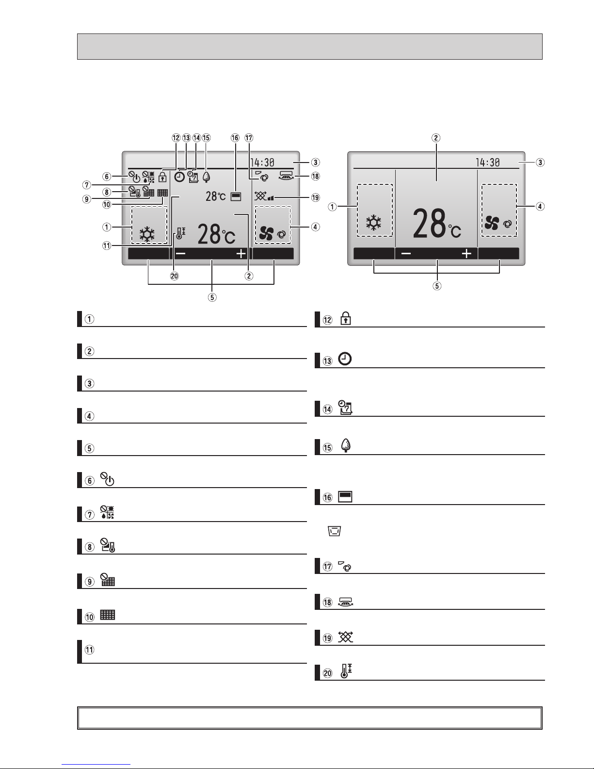
The main display can be displayed in two different modes: "Full" and "Basic".
T
he initial setting is "Full". To switch to the "Basic" mode, change the setting on the Main display setting.
<Full mode> <Basic mode>
* All icons are displayed for explanation.
Most settings (except ON / OFF, mode, fan speed, temperature) can be made from the Menu screen.
Indoor unit operation mode appears here.
Operation mode
Preset temperature appears here.
Preset temperature
Current time appears here.
Clock (See the Installation Manual.)
Fan speed
Fan speed setting appears here.
Functions of the corresponding buttons appear here.
Button function guide
Appears when the ON/OFF operation is centrally controlled.
Appears when the operation mode is centrally controlled.
Appears when the preset temperature is centrally controlled.
Appears when the lter reset function is centrally controlled.
Indicates when lter needs maintenance.
Current room temperature appears here.
Room temperature
(See the Installation Manual.)
Appears when the buttons are locked.
Appears when the On/Off timer or Night setback function is
enabled.
Appears when the Weekly timer is enabled.
Appears while the units are operated in the energy-save
mode.
Appears when the built-in thermistor on the remote controller is activated to monitor the room temperature (a).
appears when the thermistor on the indoor unit is acti-
vated to monitor the room temperature.
Indicates the vane setting.
Indicates the louver setting.
Indicates the ventilation setting.
Appears when the preset temperature range is restricted.
OCH565
8
Not all functions are available on all models of indoor units.
Filter information
Error information
Energy saving
Auto return
Schedule
Night setback
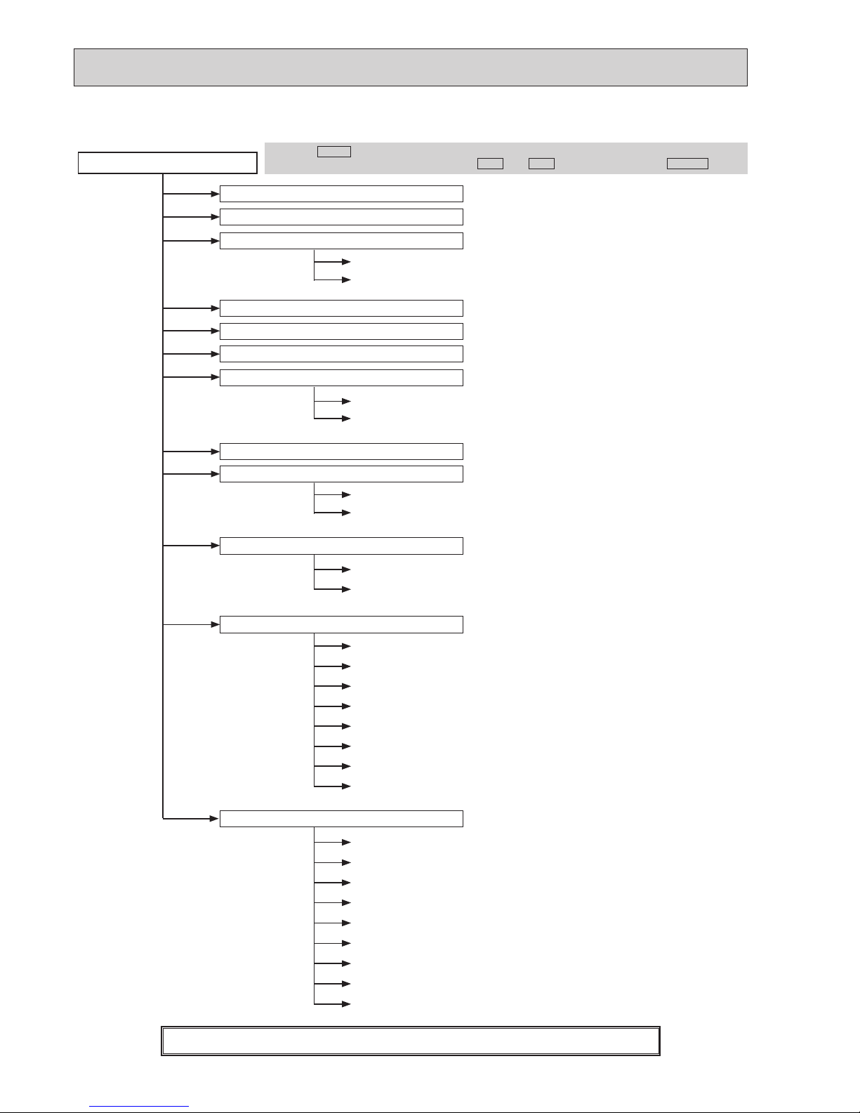
Main menu
Press the
MENU
button.
Move the cursor to the desired item with the
F1
and
F2
buttons, and press the
SELECT
button.
Vane · Louver · Vent. (Lossnay)
High power
Weekly timer
Restriction
Maintenance
Initial setting
On / Off timer
Auto-Off timer
Temp. range
Operation lock
Manual vane angle
Main / Sub
Timer
Main display
Contrast
Display details
Auto mode
Administrator password
Language selection
Service
Service menu
Input maintenance info.
Function setting
Check
Self check
Maintenance password
Remote controller check
Test run
Clock
Drain pump test run
Auto descending panel
Menu structure
OCH565
9
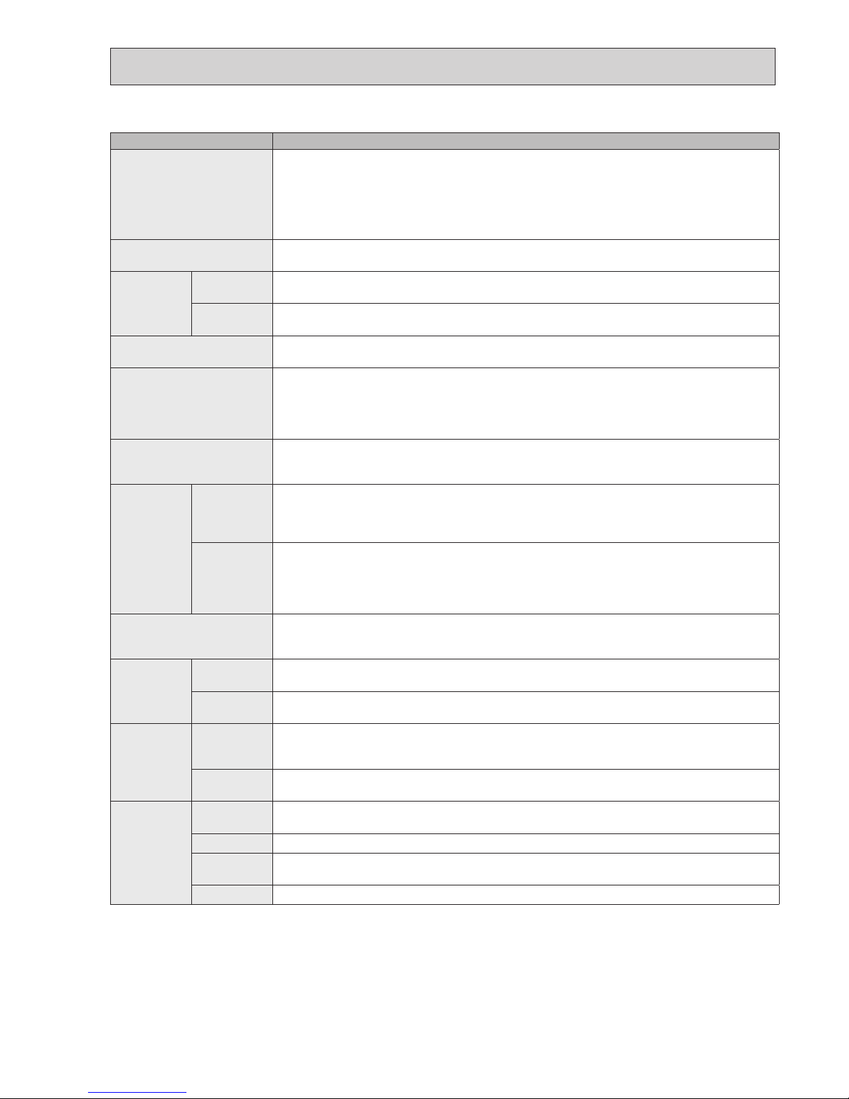
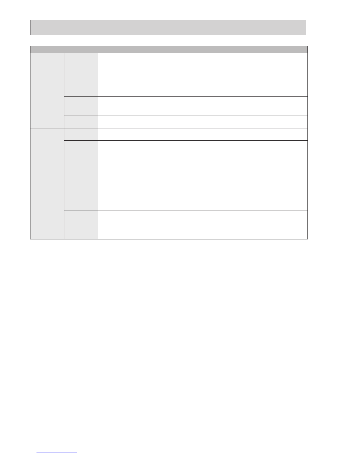
Setting and display items Setting details
Vane · Louver · Vent.
(Lossnay)
Use to set the vane angle.
• Select a desired vane setting from ve different settings.
Use to turn ON / OFF the louver.
• Select a desired setting from "ON" and "OFF."
Use to set the amount of ventilation.
• Select a desired setting from "Off," "Low," and "High."
High power Use to reach the comfortable room temperature quickly.
• Units can be operated in the High-power mode for up to 30 minutes.
Timer On/Off timer* Use to set the operation On/Off times.
• Time can be set in 5-minute increments.
Auto-Off
timer
Use to set the Auto-Off time.
• Time can be set to a value from 30 to 240 in 10-minute increments.
Filter information Use to check the lter status.
• The lter sign can be reset.
Error information Use to check error information when an error occurs.
• Check code, error source, refrigerant address, unit model, manufacturing number, contact
information (dealer's phone number) can be displayed.
(The unit model, manufacturing number, and contact information need to be registered in
advance to be displayed.)
Weekly timer* Use to set the weekly operation On / Off times.
• Up to eight operation patterns can be set for each day.
(Not valid when the On/Off timer is enabled.)
Energy
saving
Auto return Use to get the units to operate at the preset temperature after performing energy-save
operation for a specied time period.
• Time can be set to a value from 30 and 120 in 10-minute increments.
(This function will not be valid when the preset temperature ranges are restricted.)
Schedule* Set the start/stop times to operate the units in the energy-save mode for each day of the
week, and set the energy-saving rate.
• Up to four energy-save operation patterns can be set for each day.
• Time can be set in 5-minute increments.
• Energy-saving rate can be set to a value from 0% or 50 to 90% in 10% increments.
Night setback* Use to make Night setback settings.
• Select "Yes" to enable the setting, and "No" to disable the setting. The temperature range and
the start/stop times can be set.
Restriction Temp. range Use to restrict the preset temperature range.
• Different temperature ranges can be set for different operation modes.
Operation
lock
Use to lock selected functions.
• The locked functions cannot be operated.
Maintenance
Auto
descending
panel
Auto descending panel (Optional parts) Up / Down you can do.
Manual
vane angle
Use to set the vane angle for each vane to a xed position.
Initial setting
Main/Sub
When connecting two remote controllers, one of them needs to be designated as a sub
controller.
Clock
Use to set the current time.
Main display
Use to switch between "Full" and "Basic" modes for the Main display.
• The initial setting is "Full."
Contrast
Use to adjust screen contrast.
Main menu list
* Clock setting is required.
OCH565
10
Setting and display items Setting details
Initial setting Display
details
Make the settings for the remote controller related items as necessary.
Clock: The initial settings are "Yes" and "24h" format.
Temperature: Set either Celsius (°C) or Fahrenheit (°F).
Room temp. : Set Show or Hide.
Auto mode: Set the Auto mode display or Only Auto display.
Auto mode Whether or not to use the AUTO mode can be selected by using the button.
This setting is valid only when indoor units with the AUTO mode function are connected.
Administrator
password
The administrator password is required to make the settings for the following items.
•
Timer setting • Energy-save setting • Weekly timer setting
•
Restriction setting • Outdoor unit silent mode setting • Night set back
Language
selection
Use to select the desired language.
Service
Test run Select "Test run" from the Service menu to bring up the Test run menu.
•
Test run • Drain pump test run
Input
maintenance
Select "Input maintenance Info." from the Service menu to bring up the Maintenance
information screen.
The following settings can be made from the Maintenance Information screen.
•
Model name input • Serial No. input • Dealer information input
Function
setting
Make the settings for the indoor unit functions via the remote controller as necessary.
Check Check code history: Display the check code history and execute delete check code history.
Refrigerant leak check: Refrigerant leaks can be judged.
Smooth maintenance: The indoor and outdoor maintenance data can be displayed.
Request cord: Details of the operation data including each thermistor temperature and check
code history can be checked.
Self check Check code history of each unit can be checked via the remote controller.
Maintenance
password
Take the following steps to change the maintenance password.
Remote
controller
check
When the remote controller does not work properly, use the remote controller checking
function to troublushoot the problem.
OCH565
11
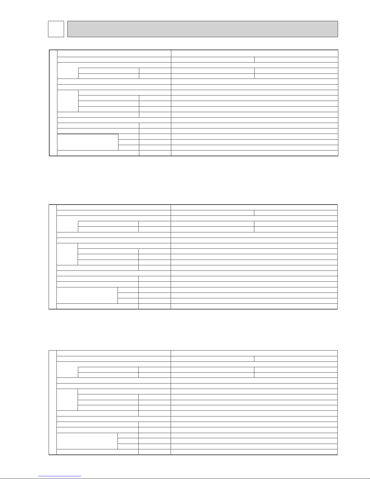
SPECIFICATIONS
4
Cooling
0.14
0.94
Heating
0.13
0.87
Single phase, 50Hz, 230V
Munsell 6.4Y 8.9/0.4
Plate fin coil
Turbo fan (direct) o 1
0.120
20-23-26-30(710-810-920-1,060)
0(direct blow)
–
Remote controller & built-in
32-34-37-40
32(1-1/4)
kW
A
kW
K/min(CFM)
Pa(mmAq)
kW
dB
mm(in)
mm(in)
mm(in)
mm(in)
kg(lb)
W
D
H
INDOOR UNIT
PLA-SP100BA.UK
Service Ref.
Mode
Power supply (phase, cycle, voltage)
Input
Running current
External finish (Panel)
Heat exchanger
Fan Fan (drive) o No.
Fan motor output
Airflow (Low-Medium2-Medium1-High)
External static pressure
Booster heater
Operation control & Thermostat
Noise level (Low-Medium2-Medium1-High)
Field drain pipe O.D.
Dimensions
Weight
: 840 (33-1/16) PANEL: 950 (37-3/8)
: 840 (33-1/16) PANEL: 950 (37-3/8)
: 298 (11-3/4) PANEL: 35 (1-3/8)
: 25 (55) PANEL: 6 (13)
UNIT
UNIT
UNIT
UNIT
Cooling
0.15
1.00
Heating
0.14
0.94
Single phase, 50Hz, 230V
Munsell 6.4Y 8.9/0.4
Plate fin coil
Turbo fan (direct) o 1
0.120
22-25-28-31(780-880-990-1,090)
0(direct blow)
–
Remote controller & built-in
34-36-39-41
32(1-1/4)
kW
A
kW
K/min(CFM)
Pa(mmAq)
kW
dB
mm(in)
mm(in)
mm(in)
mm(in)
kg(lb)
W
D
H
INDOOR UNIT
PLA-SP125BA.UK
Service Ref.
Mode
Power supply (phase, cycle, voltage)
Input
Running current
External finish (Panel)
Heat exchanger
Fan Fan (drive) o No.
Fan motor output
Airflow (Low-Medium2-Medium1-High)
External static pressure
Booster heater
Operation control & Thermostat
Noise level (Low-Medium2-Medium1-High)
Field drain pipe O.D.
Dimensions
Weight
: 840 (33-1/16) PANEL: 950 (37-3/8)
: 840 (33-1/16) PANEL: 950 (37-3/8)
: 298 (11-3/4) PANEL: 35 (1-3/8)
: 25 (55) PANEL: 6 (13)UNIT
UNIT
UNIT
UNIT
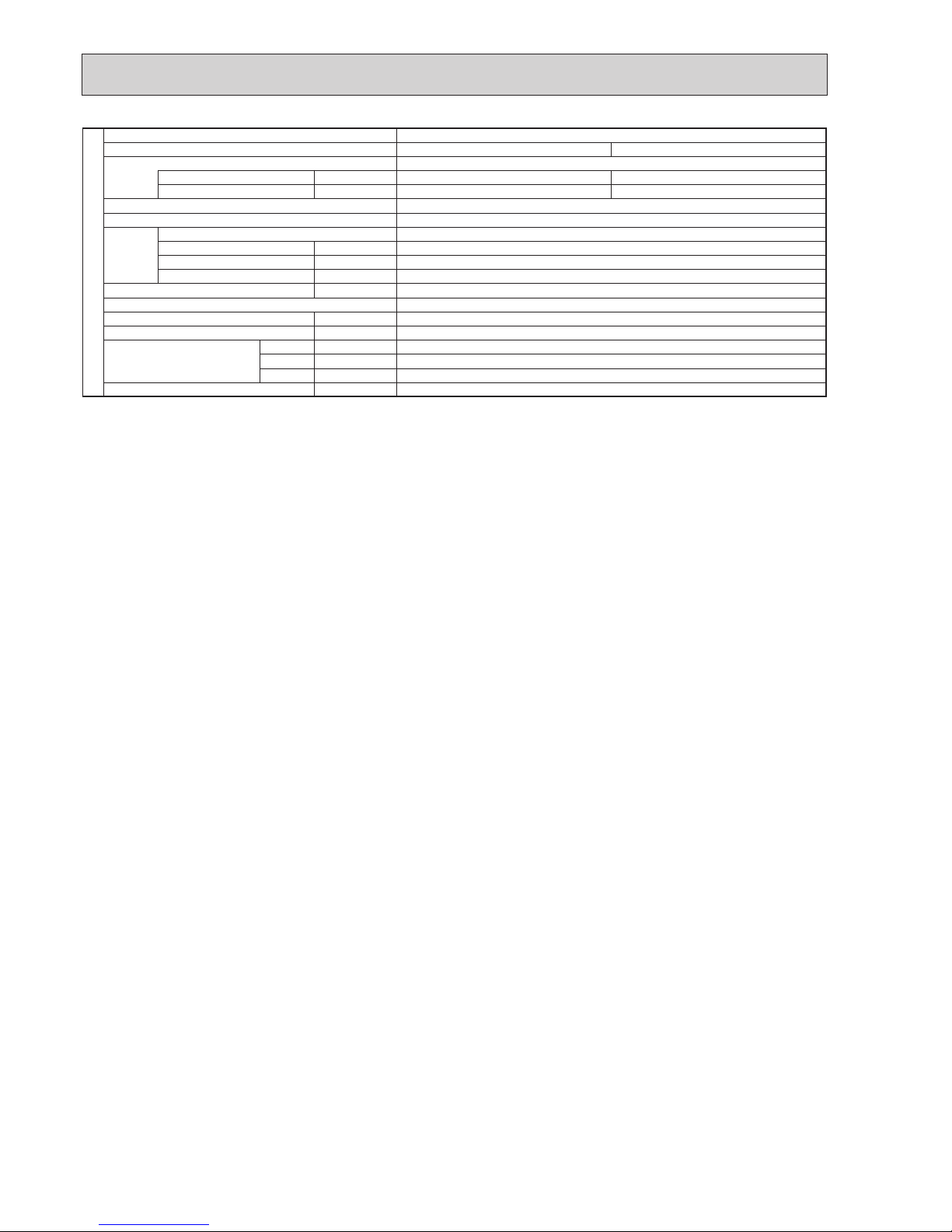
Cooling
0.07
0.51
Heating
0.06
0.43
Single phase, 50Hz, 230V
Munsell 6.4Y 8.9/0.4
Plate fin coil
Turbo fan (direct) o 1
0.050
14-16-18-21(485-565-635-740)
0(direct blow)
–
Remote controller & built-in
28-30-32-34
32(1-1/4)
kW
A
kW
K/min(CFM)
Pa(mmAq)
kW
dB
mm(in)
mm(in)
mm(in)
mm(in)
kg(lb)
Mode
Power supply (phase, cycle, voltage)
Input
Running current
External finish (Panel)
Heat exchanger
Fan Fan (drive) o No.
Fan motor output
Airflow (Low-Medium2-Medium1-High)
External static pressure
Booster heater
Operation control & Thermostat
Noise level (Low-Medium2-Medium1-High)
Field drain pipe O.D.
Dimensions
Weight
W
D
H
INDOOR UNIT
PLA-SP71BA.UK
UNIT : 840 (33-1/16) PANEL : 950 (37-3/8)
UNIT : 840 (33-1/16) PANEL : 950 (37-3/8)
UNIT : 258 (10-3/16) PANEL : 35 (1-3/8)
UNIT : 23 (51) PANEL: 6 (13)
Service Ref.
OCH565
12
kW
A
kW
K/min(CFM)
Pa(mmAq)
kW
dB
mm(in)
mm(in)
mm(in)
mm(in)
kg(lb)
Service Ref.
Mode
Power supply (phase, cycle, voltage)
Input
Running current
External finish (Panel)
Heat exchanger
Fan Fan(drive) o No.
Fan motor output
Airflow (Low-Medium2-Medium1-High)
External static pressure
Booster heater
Operation control & Thermostat
Noise level (Low-Medium2-Medium1-High)
Field drain pipe O.D.
Dimensions
Weight
W
D
H
INDOOR UNIT
PLA-SP140BA.UK
Cooling
0.16
1.07
Heating
0.15
1.00
Single phase, 50Hz, 230V
Munsell 6.4Y 8.9/0.4
Plate fin coil
Turbo fan (direct) o 1
0.120
24-26-29-32(850-920-1,020-1,130)
0(direct blow)
–
Remote controller & built-in
36-39-42-44
32(1-1/4)
: 840 (33-1/16) PANEL: 950 (37-3/8)
: 840 (33-1/16) PANEL: 950 (37-3/8)
: 298 (11-3/4) PANEL: 35 (1-3/8)
: 27 (60) PANEL: 6 (13)UNIT
UNIT
UNIT
UNIT
OCH565
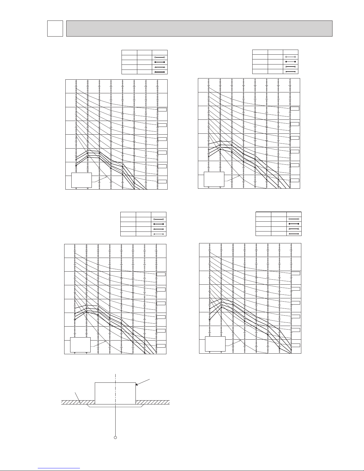
13
5
NOISE CRITERION CURVES
PLA-SP71BA.UK
NOTCH SPL(dB) LINE
High 34
Medium1 32
Medium2 30
Low 28
90
80
70
60
50
40
30
20
10
63 125 250 500 1000 2000 4000 8000
APPROXIMATE
THRESHOLD OF
HEARING FOR
CONTINUOUS
NOISE
NC-60
NC-50
NC-40
NC-30
NC-20
NC-70
BAND CENTER FREQUENCIES, Hz
OCTAVE .UKND SOUND PRESSURE LEVEL, dB (0 dB = 0.0002 μbar)
PLA-SP100BA.UK
NOTCH SPL(dB) LINE
High 40
Medium1 37
Medium2 34
Low 32
90
80
70
60
50
40
30
20
10
63 125 250 500 1000 2000 4000 8000
APPROXIMATE
THRESHOLD OF
HEARING FOR
CONTINUOUS
NOISE
NC-60
NC-50
NC-40
NC-30
NC-20
NC-70
OCTAVE BAND SOUND PRESSURE LEVEL, dB (0 dB = 0.0002 μbar)
BAND CENTER FREQUENCIES, Hz
PLA-SP125BA.UK
NOTCH SPL(dB) LINE
High 41
Medium1 39
Medium2 36
Low 34
OCTAVE BAND SOUND PRESSURE LEVEL, dB (0 dB = 0.0002 μbar)
90
80
70
60
50
40
30
20
10
63 125 250 500 1000 2000 4000 8000
APPROXIMATE
THRESHOLD OF
HEARING FOR
CONTINUOUS
NOISE
NC-60
NC-50
NC-40
NC-30
NC-20
NC-70
BAND CENTER FREQUENCIES, Hz
PLA-SP140BA.UK
NOTCH SPL(dB) LINE
High 44
Medium1 42
Medium2 39
Low 36
90
80
70
60
50
40
30
20
10
63 125 250 500 1000 2000 4000 8000
APPROXIMATE
THRESHOLD OF
HEARING FOR
CONTINUOUS
NOISE
NC-60
NC-50
NC-40
NC-30
NC-20
NC-70
OCTAVE BAND SOUND PRESSURE LEVEL, dB (0 dB = 0.0002 μbar)
BAND CENTER FREQUENCIES, Hz
UNIT
1.5m
MICROPHONE
CEILING
OCH565
14
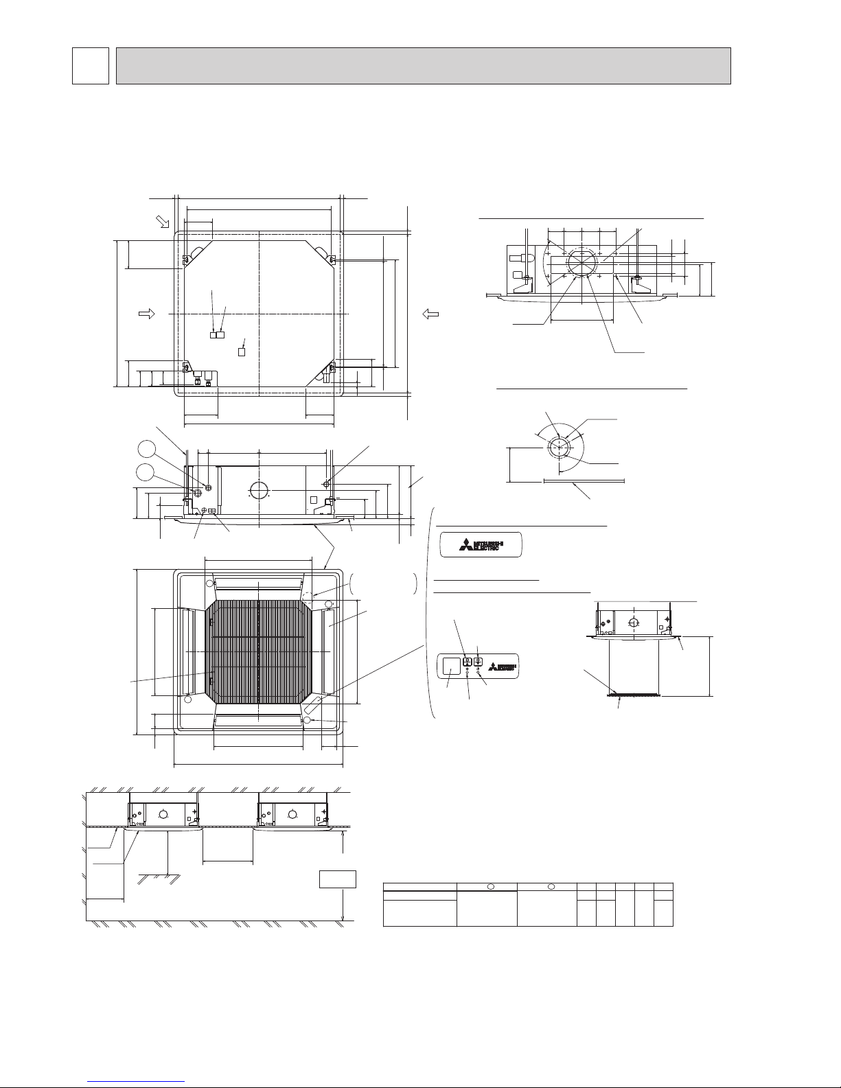
6
OUTLINES AND DIMENSIONS
37728460
( )
Ceiling hole
Branch duct hole
Drain pipe
connected to VP-25
Ceiling
Grille
Drain hole
Auto vane
(Air outlet)
Air intake grille
Ceiling
Cut out hole
Cut out hole
Cut out hole
Burring hole pitch
Burring hole pitch
Burring hole
Burring hole
Power supply wire,
Indoor unit/Outdoor unit
connecting wire entry
Indoor unit/Outdoor unit
connecting terminal block
Indoor power supply
terminal block(Optional parts)
Control wire entry
Air intake hole
Air intake hole
Air outlet hole
Air outlet hole
Connected the attached
flexible pipe or socket.
Keep approximately
10 to 15mm space
between unit ceiling
and ceiling slab.
Branch duct hole
Fresh air
intake hole
Ceiling hole
Suspension bolt pitch
Suspension bolt pitch
Remote controller
terminal block
Suspension bolt
M10 or W3/8
(7.5)(7.5)
605
620
DEFROST/STAND BY lamp
Receiver
Operation lamp
In case of standard grille : PLP-6BA / PLP-6BAMD
In case of wireless remote controller : PLP-6BALM Auto grille
Air intake grille up/down distance
Emergency operation
switch<Cooling>and
Emergency Up/Down switch<Up>
160
160
500
500
597
83 36
950
8336
950
597
A
17
+5
0
B35
190
156
105
140
50~70
160
840
150
90
C
D
840
187.5
20~45
860~910
20~45
810
20~45
860~910
20~45
24
160
M
M
M
M
120°
120°
{175
[125
167
158
Vane motor
2
1
Drain pump clean hole
and Drain emergency
drainage hole
130
100
70°
155
*
350
90 100 100 90
Detail drawing of fresh air intake hole
Detail connecting of branch duct(Both aspects)
3-[2.8
14-[2.8
[150
[100
Model
BA C D E
241 258
400
298
85 77
440
281
2
1
Refrigerant pipe
···[9.52
Flared connection
···3/8 inch
Refrigerant pipe
···[15.88
Flared connection
···5/8 inch
PLA-SP71BA
PLA-SP100BA
PLA-SP125BA
PLA-SP140BA
Emergency operation
switch<Heating>and
Emergency Up/Down switch<Down>
In case of auto-grille : PLP-6BAJ
Suspension bolt
lower edge
170
*
*
*
*
*
*
*
*
*
Ceiling
Air intake grille
Max. 4.0m
L.L Filter
Ceiling
Grille
Indoor unit
1500mm
or more
1000mm
or more
3000mm or more
2500mm or more
from floor
For high
attachment
Indoor unit
Obstacle
Floor
Note1. Please choose the grille from a standard grille, auto-grille.
2. As for drain pipe, please use VP-25(O.D.
[
32 PVC TUBE).
Drain pump is included.
Max. lifting height is 850mm from the ceiling.
3. As for suspension bolt, please use M10 or W3/8.
(Procured at local site)
4. Electrical box may be removed for the service purpose.
Make sure to slack the electrical wire little bit for control/power wires connection.
5. The height of the indoor unit is able to be adjusted with the grille attached.
6. For the installation of the optional high efficiency filter or optional multi-functional casement.
1) Requires E or more space between transom and ceiling for the installation.
2) Add 135 mm to the dimensions
*
marked on the figure.
3) The optional high efficiency filter must be used jointly with the optional multi-functional casement.
7. When installing the branch ducts, be sure to insulate adequately.
Otherwise condensation and dripping may occur.
(It becomes the cause of dew drops/Water dew.)
8. As for necessary installation/service space, please refer to the left figure.
PLA-SP71BA.UK PLA-SP100BA.UK PLA-SP125BA.UK PLA-SP140BA.UK
Unit: mm
OCH565
 Loading...