

Page 1
SPLIT-TYPE, HEAT PUMP AIR CONDITIONERS
May 2005
No. OCS01
TECHNICAL DATA BOOK
<Indoor unit>
[Model names]
<Outdoor unit>
[Model names]
PLA-RP·AA
PEAD-RP·EA
PEAD-RP·GA
PEA-RP·EA
PEH-RP·MYA
PKA-RP·GAL
PKA-RP·FAL
PCA-RP·GA
PCA-RP·HA
PSA-RP·GA
PUHZ-RP35/50/60/71/100/125/140VHA
R410A
INVERTER
PUHZ-RP100/125/140/200/250YHA
CONTENTS
1. REFERENCE SERVICE MANUAL·············································2
2. SPECIFICATIONS ······································································3
3. OUTLINES AND DIMENSIONS················································26
4. WIRING DIAGRAM···································································52
5. REFRIGERANT SYSTEM DIAGRAM ······································66
6. PERFORMANCE CURVES······················································69
7. CORRECTION FACTORS························································73
8. APPLICABLE EXTENSION PIPE FOR EACH MODEL··········74
9. AIR FLOW DATA······································································82
10. NOISE CRITERION CURVES ················································100
11. OPTIONAL PARTS···································································116
kW Model
Page 2
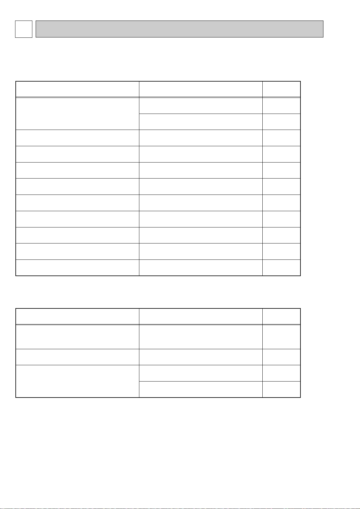
For information on service, please refer to the service manual as follows.
Model name Service Ref. Service
Manual No.
PLA-RP35/50/60/71AA PLA-RP35/50/60/71AA.UK OC335
PLA-RP100/125/140AA
PLA-RP100/125/140AA.UK
PLA-RP35/50/60/71AA OC327
PLA-RP100/125/140AA.UK
PCA-RP50/60/71GA PCA-RP50/60/71GA OC328
PCA-RP100/125/140GA
PCA-RP100/125/140GA
PCA-RP71/125HA PCA-RP71/125HA OC329
PKA-RP35/50GAL PKA-RP35/50GAL OC330
PKA-RP60/71/100FAL PKA-RP60/71/100FAL OC331
PSA-RP71/100/125/140GA PSA-RP71/100/125/140GA OC332
PEA-RP71/100/125/140EA PEA-RP71/100/125/140EA.TH-A OC326
PEAD-RP35/50/60/71EA PEAD-RP35/50/60/71EA.UK -
PEAD-RP100/125/140EA
PEAD-RP100/125/140EA.UK
PEAD-RP60/71/100GA PEAD-RP60/71/100GA.UK PEH-RP200/250MYA PEH-RP200/250MYA -
1-2. OUTDOOR UNIT
Model name Service Ref. Service
Manual No.
PUHZ-RP35/50/60/71VHA PUHZ-RP35/50/60/71VHA OC334
PUHZ-RP100/125/140VHA
PUHZ-RP100/125/140VHA
PUHZ-RP100/125/140YHA
PUHZ-RP100/125/140YHA
PUHZ-RP100/125/140VHA PUHZ-RP71/100/125/140VHA-A OC337
PUHZ-RP200/250YHA PUHZ-RP200/250YHA OC338
PUHZ-RP200/250YHA-A OC339
1-1. INDOOR UNIT
1
REFERENCE SERVICE MANUAL
2
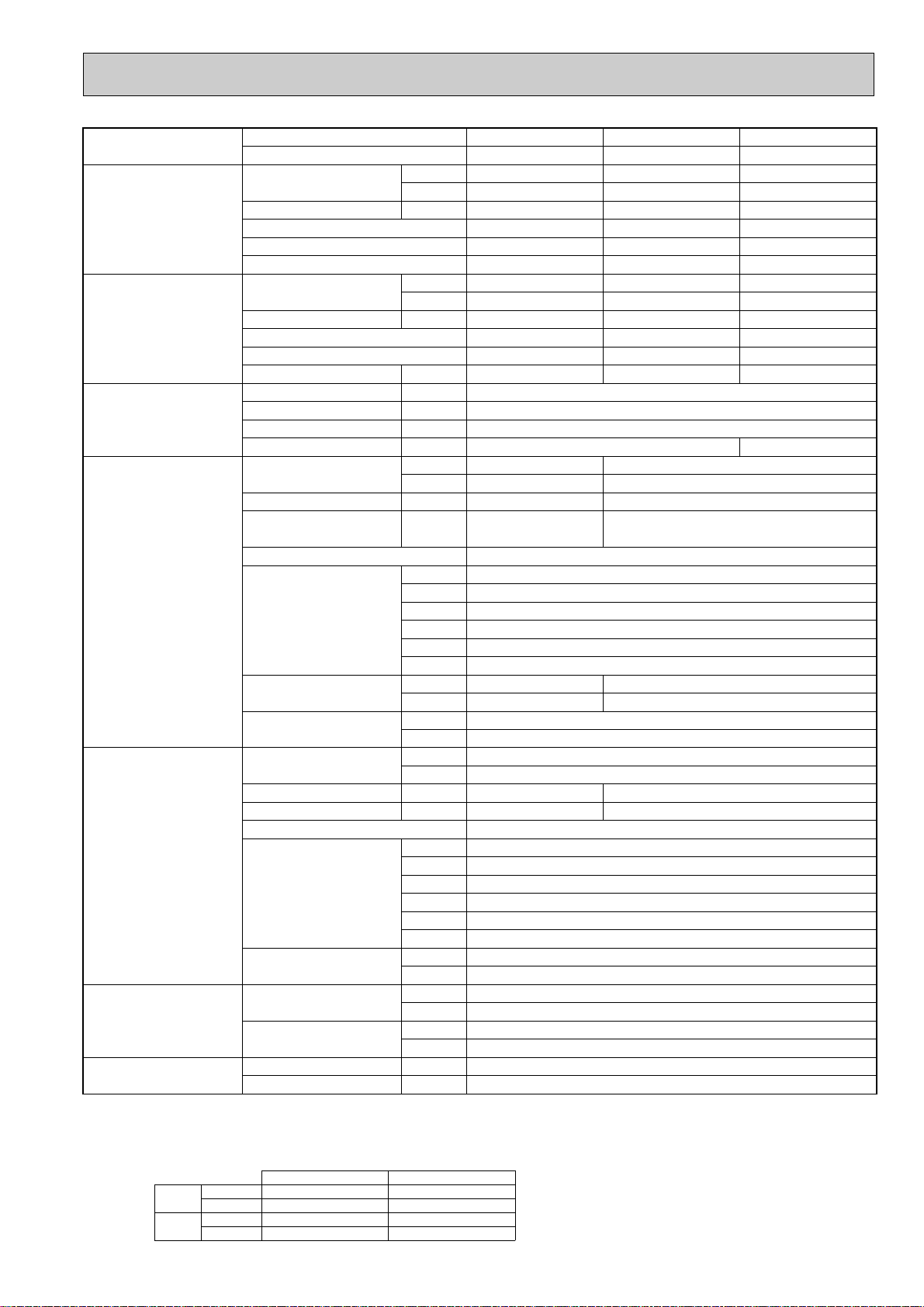
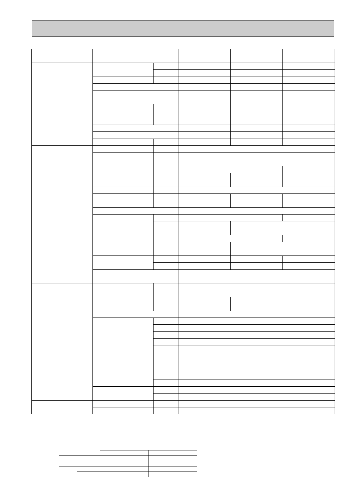
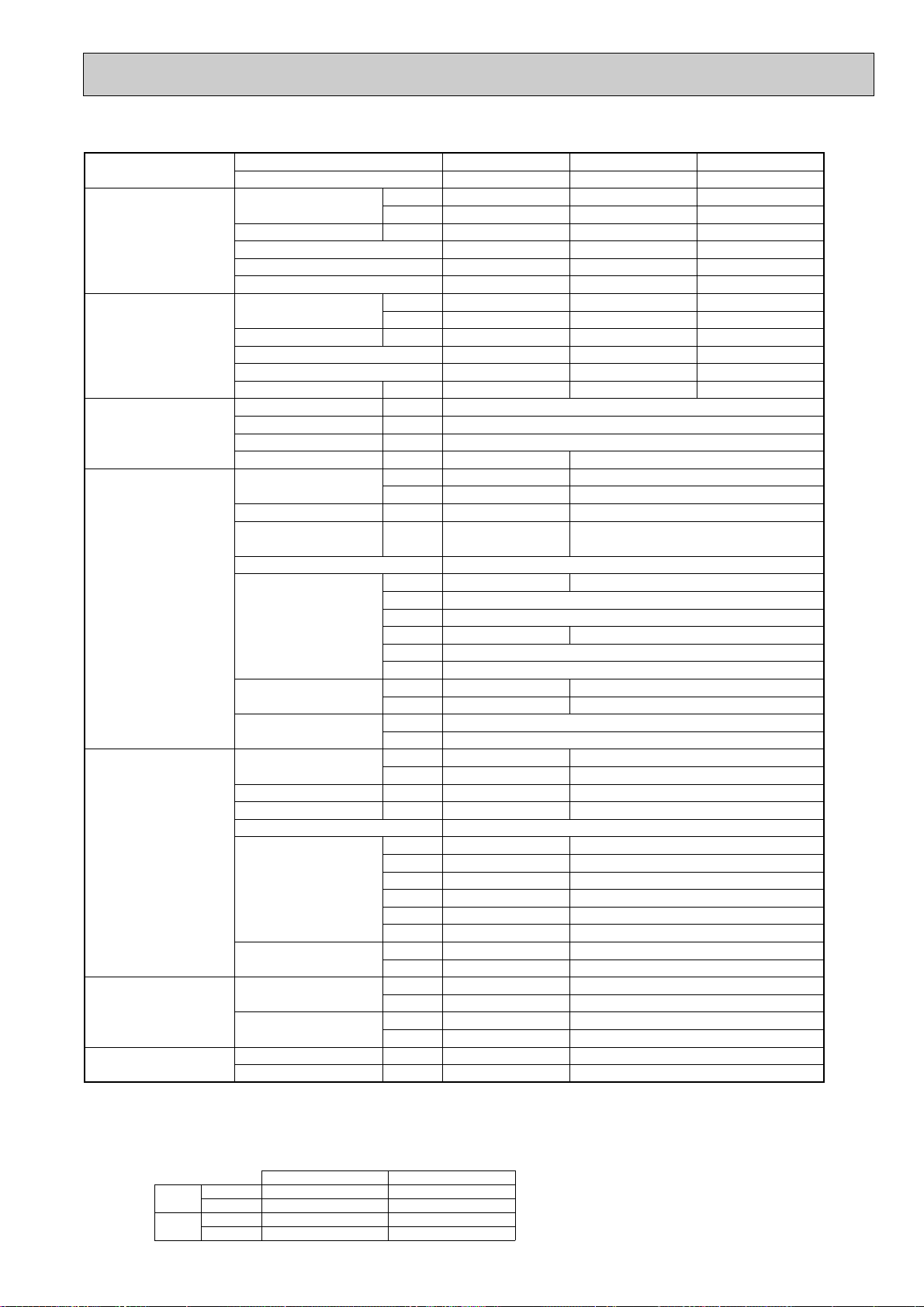
Page 3
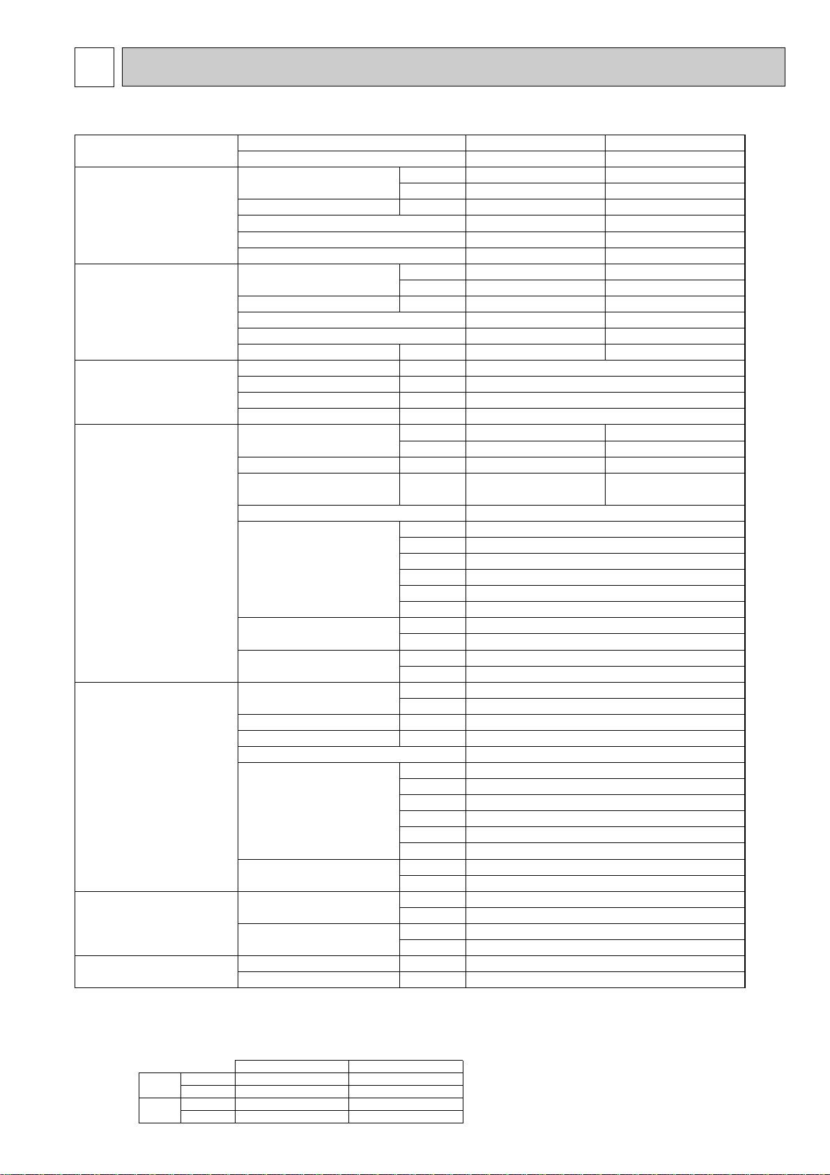
2
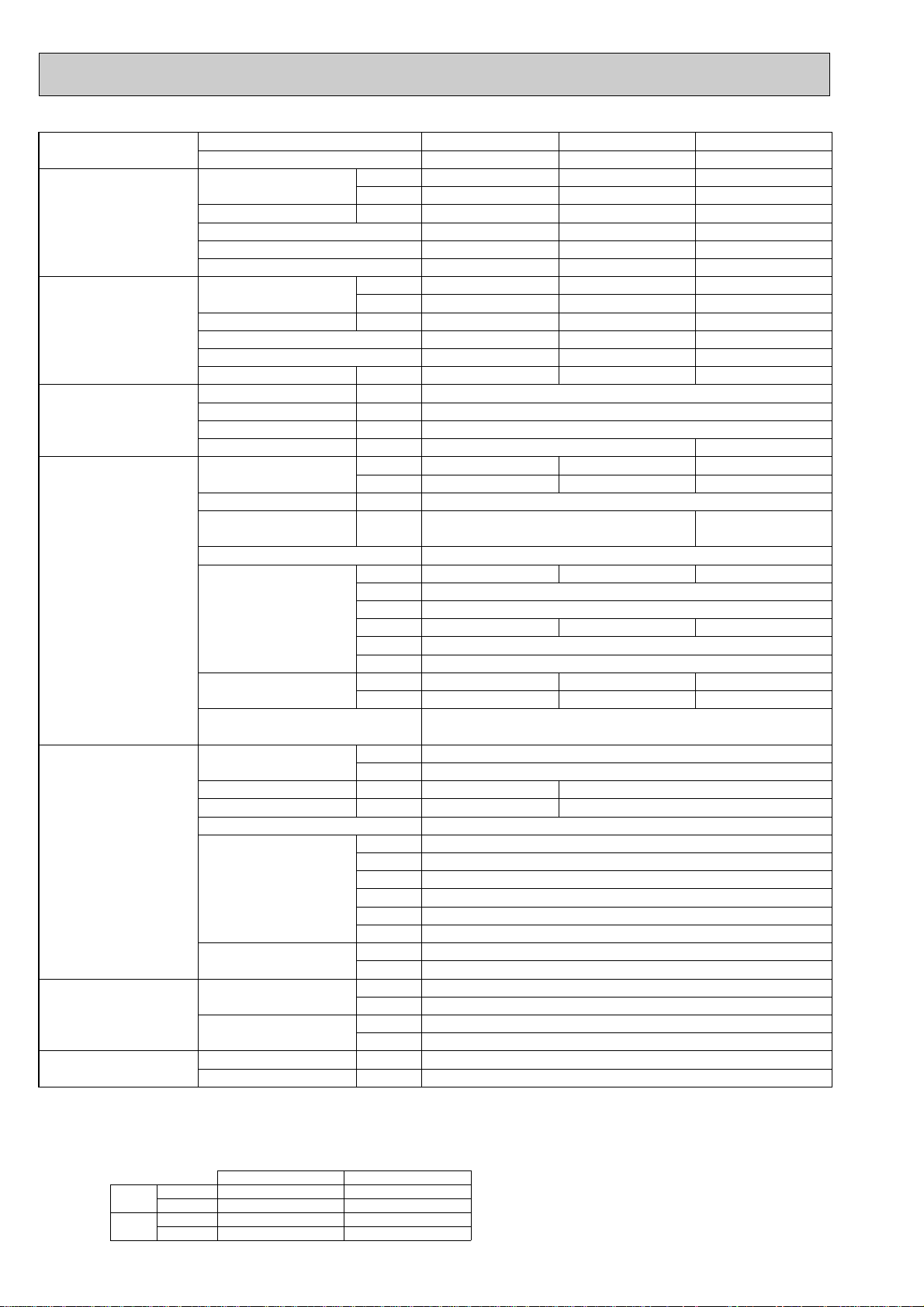
Model name Indoor unit PLA-RP35AA PLA-RP50AA
Outdoor unit PUHZ-RP35VHA PUHZ-RP50VHA
Cooling Capacity Btu/h 12,300 17,100
kW 3.6(1.6-4.5) 5.0(2.3-5.6)
Total input kW 1.07 1.55
EER 3.36 3.23
Energy label class A A
SHF 0.89 0.86
Heating Capacity Btu/h 14,000 20,500
kW 4.1(1.6-5.2) 6.0(2.5-7.3)
Total input kW 1.12 1.62
COP 3.66 3.70
Energy label class A A
Booster heater kW - -
Power supply Phase [ 1
Cycle Hz 50
Voltage V 230
Breaker size A 16
Indoor unit Air flow CMM 11-12-13-14 14-15-16-18
(Low-Medium2-Medium1-High)
CFM 390-425-460-495 495-530-565-635
External pressure Pa 0 0
Sound level dB(A) 27-28-29-31 28-29-31-33
(Low-Medium2-Medium1-High)
External finish (Panel) White Munsell 0.70Y 8.59/0.97
Dimension W : mm 840 (950)
Unit (Panel) D : mm 840 (950)
H : mm 258 (30)
W : inch 33-1/16 (37-3/8)
D : inch 33-1/16 (37-3/8)
H : inch 10-3/16 (1-3/16)
Weight kg 24 (5)
Unit (Panel) lbs 53 (11)
Unit drain pipe I.D. mm 32
inch 1-1/4
Outdoor unit Air flow CMM 35
CFM 1,240
Sound level at cooling dB(A) 44
Sound level at heating dB(A) 46
External finish Ivory Munsell 3Y 7.8/1.1
Dimension W : mm 800
D : mm 330+23
H : mm 600
W : inch 31-1/2
D : inch 13 + 7/8
H : inch 23-5/8
Weight kg 45
lbs 99
Refrigerant pipe size Gas side O.D. mm 12.7
inch 1/2
Liquid side O.D. mm 6.35
inch 1/4
Refrigerant pipe length Height difference m Max. 30
Length m Max. 50
NOTE: 1. Rating conditions (ISO T1)
Cooling Indoor : D.B. 27: (80˚F) W.B. 19: (66˚F) Outdoor : D.B. 35: (95˚F) W.B. 24: (75˚F)
Heating Indoor: D.B. 20: (68˚F) Outdoor : D.B. 7: (45˚F) W.B. 6: (43˚F)
Refrigerant piping length (one way) : 5m (16ft.)
2. Guaranteed operating range
Indoor Outdoor
Cooling
Upper limit
D.B. 35˚C, W.B. 22.5˚C
D.B. 46˚C
Lower limit
D.B. 19˚C, W.B. 15˚C D.B. -5˚C w
Heating
Upper limit
D.B. 28˚C
D.B. 21˚C, W.B. 15˚C
Lower limit
D.B. 17˚C
D.B. -11˚C, W.B. -12˚C
4. Above data based on indicated voltage
w If optional Air protect guide installed. D.B.-15:
Indoor unit Single phase 230V 50Hz
Single phase 230V 50Hz
Outdoor unit
3. Guaranteed voltage
198~264V, 50Hz
SPECIFICATIONS
2-1. CEILING CASSETTE TYPE
3
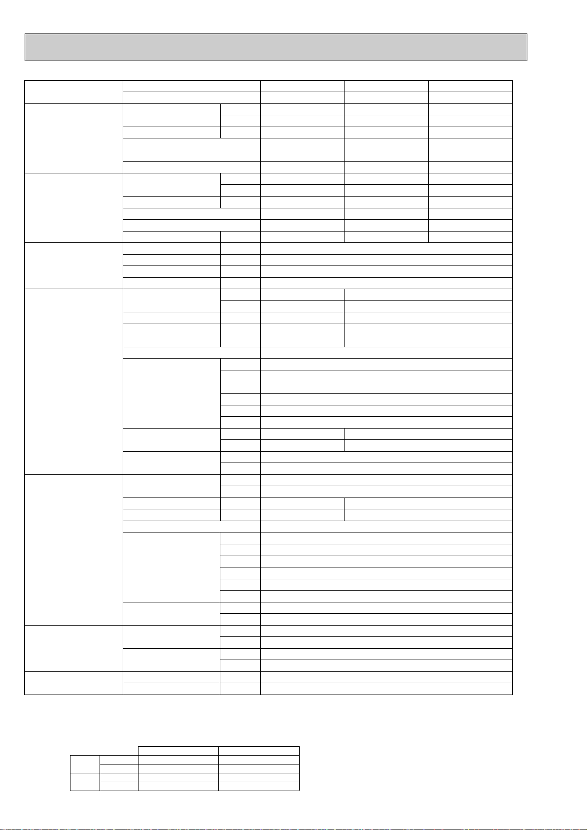
Page 4
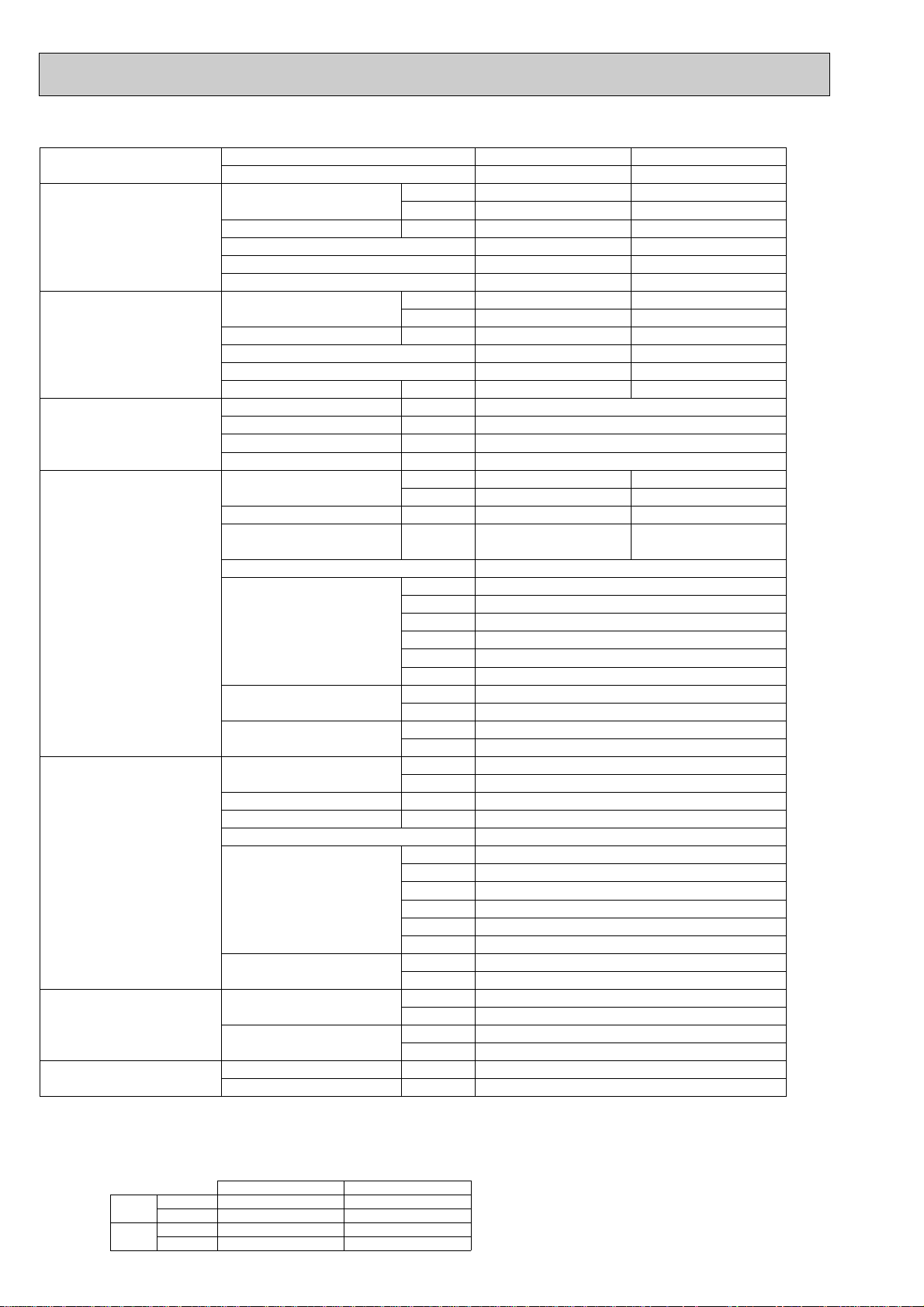
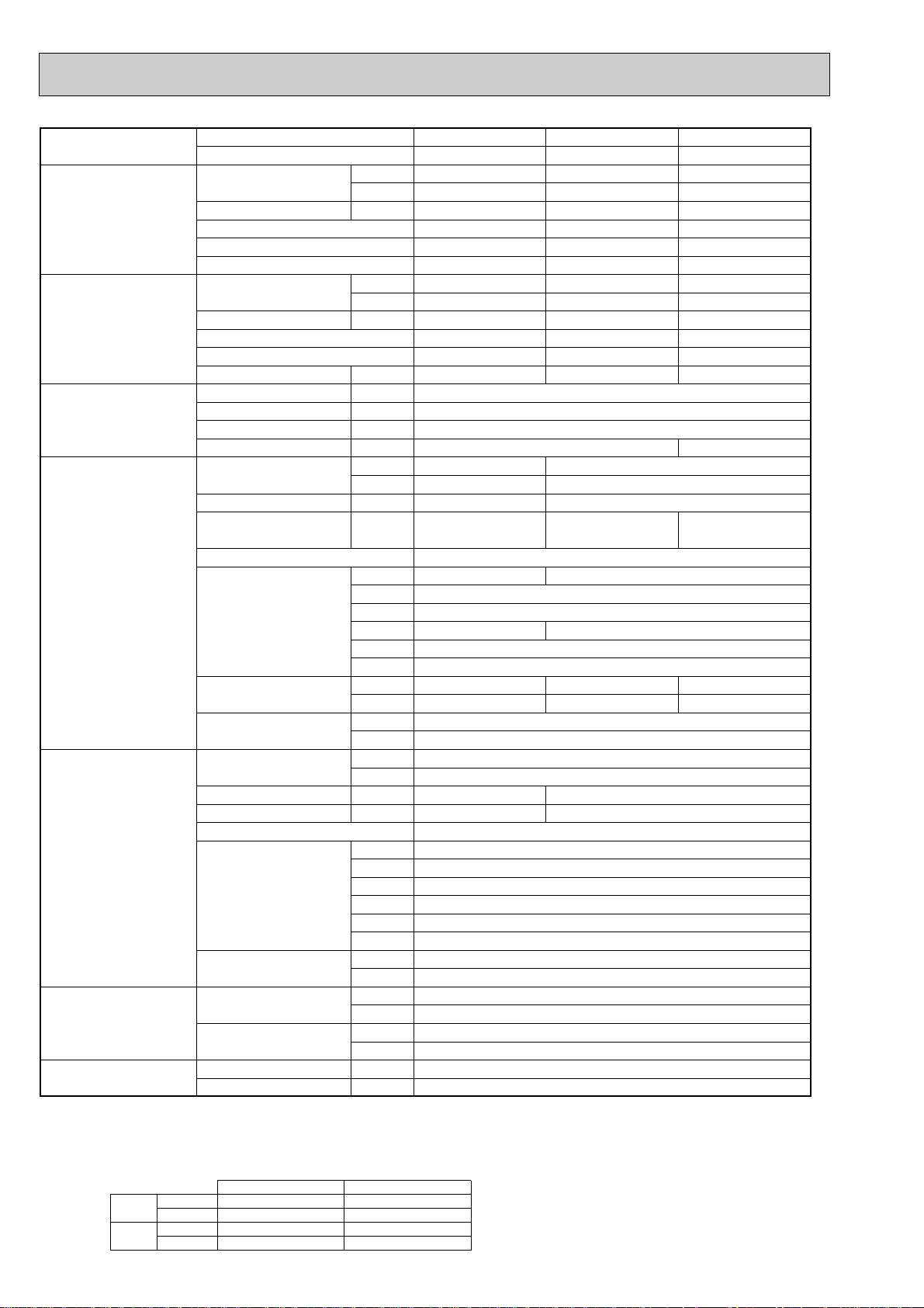
Model name Indoor unit PLA-RP60AA PLA-RP71AA
Outdoor unit PUHZ-RP60VHA PUHZ-RP71VHA
Cooling Capacity Btu/h 20,500 24,200
kW 6.0(2.7-6.7) 7.1(3.3-8.1)
Total input kW 1.65 1.97
EER 3.64 3.60
Energy label class A A
SHF 0.78 0.74
Heating Capacity Btu/h 23,900 27,300
kW 7.0(2.8-8.2) 8.0(3.5-10.2)
Total input kW 1.85 2.34
COP 3.78 3.42
Energy label class A B
Booster heater kW - -
Power supply Phase [ 1
Cycle Hz 50
Voltage V 230
Breaker size A 25
Indoor unit Air flow CMM 14-15-16-18 15-16-18-20
(Low-Medium2-Medium1-High) CFM 495-530-565-635 530-565-635-705
External pressure Pa 0 0
Sound level dB(A) 28-29-31-33 28-30-32-34
(Low-Medium2-Medium1-High)
External finish (Panel) White Munsell 0.70Y 8.59/0.97
Dimension W : mm 840 (950)
Unit (Panel) D : mm 840 (950)
H : mm 258 (30)
W : inch 33-1/16 (37-3/8)
D : inch 33-1/16 (37-3/8)
H : inch 10-3/16 (1-3/16)
Weight kg 24 (5)
Unit (Panel) lbs 53 (11)
Unit drain pipe I.D. mm 32
inch 1-1/4
Outdoor unit Air flow CMM 55
CFM 1,940
Sound level at cooling dB(A) 47
Sound level at heating dB(A) 48
External finish Ivory Munsell 3Y 7.8/1.1
Dimension W : mm 950
D : mm 330+30
H : mm 943
W : inch 37-3/8
D : inch 13 + 1-3/16
H : inch 37-1/8
Weight kg 75
lbs 165
Refrigerant pipe size Gas side O.D. mm 15.88
inch 5/8
Liquid side O.D. mm 9.52
inch 3/8
Refrigerant pipe length Height difference m Max. 30
Length m Max. 50
NOTE: 1. Rating conditions (ISO T1)
Cooling Indoor : D.B. 27: (80˚F) W.B. 19: (66˚F) Outdoor : D.B. 35: (95˚F) W.B. 24: (75˚F)
Heating Indoor: D.B. 20: (68˚F) Outdoor : D.B. 7: (45˚F) W.B. 6: (43˚F)
Refrigerant piping length (one way) : 5m (16ft.)
2. Guaranteed operating range
Cooling
Heating
Upper limit
Lower limit
Upper limit
Lower limit
D.B. 35˚C, W.B. 22.5˚C
D.B. 19˚C, W.B. 15˚C D.B. -5˚C w
D.B. 28˚C
D.B. 17˚C
Indoor Outdoor
D.B. 46˚C
D.B. 21˚C, W.B. 15˚C
D.B. -11˚C, W.B. -12˚C
3. Guaranteed voltage
198~264V, 50Hz
4. Above data based on indicated voltage
Indoor unit Single phase 230V 50Hz
Outdoor unit
w If optional Air protect guide installed. D.B.-15:
Single phase 230V 50Hz
4
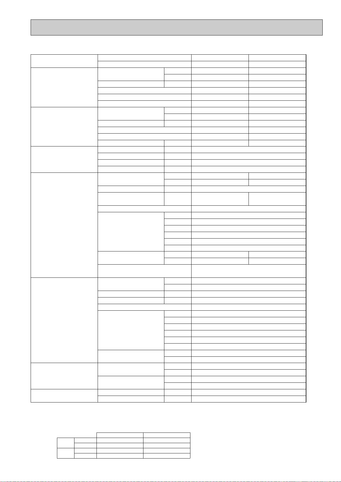
Page 5
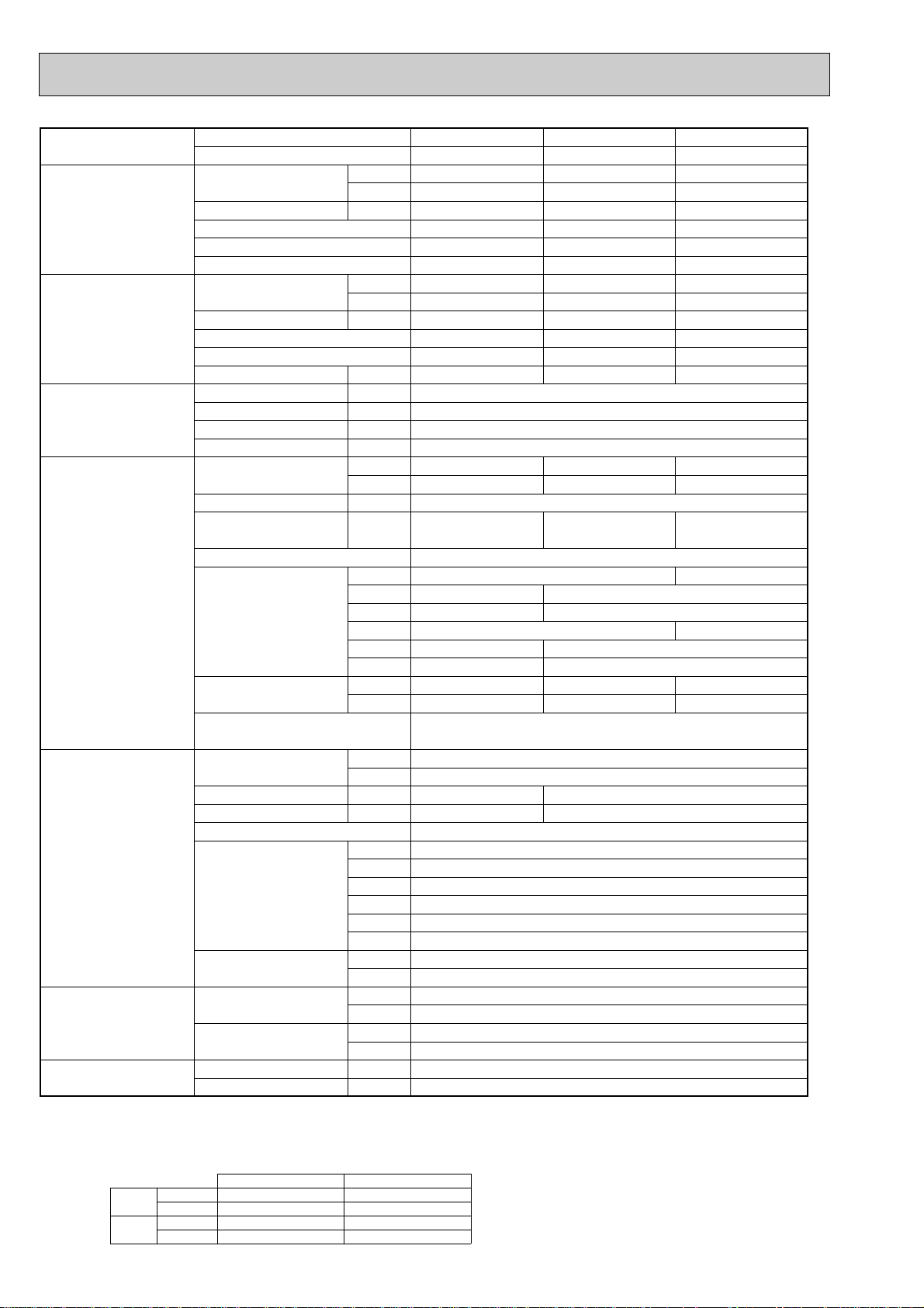
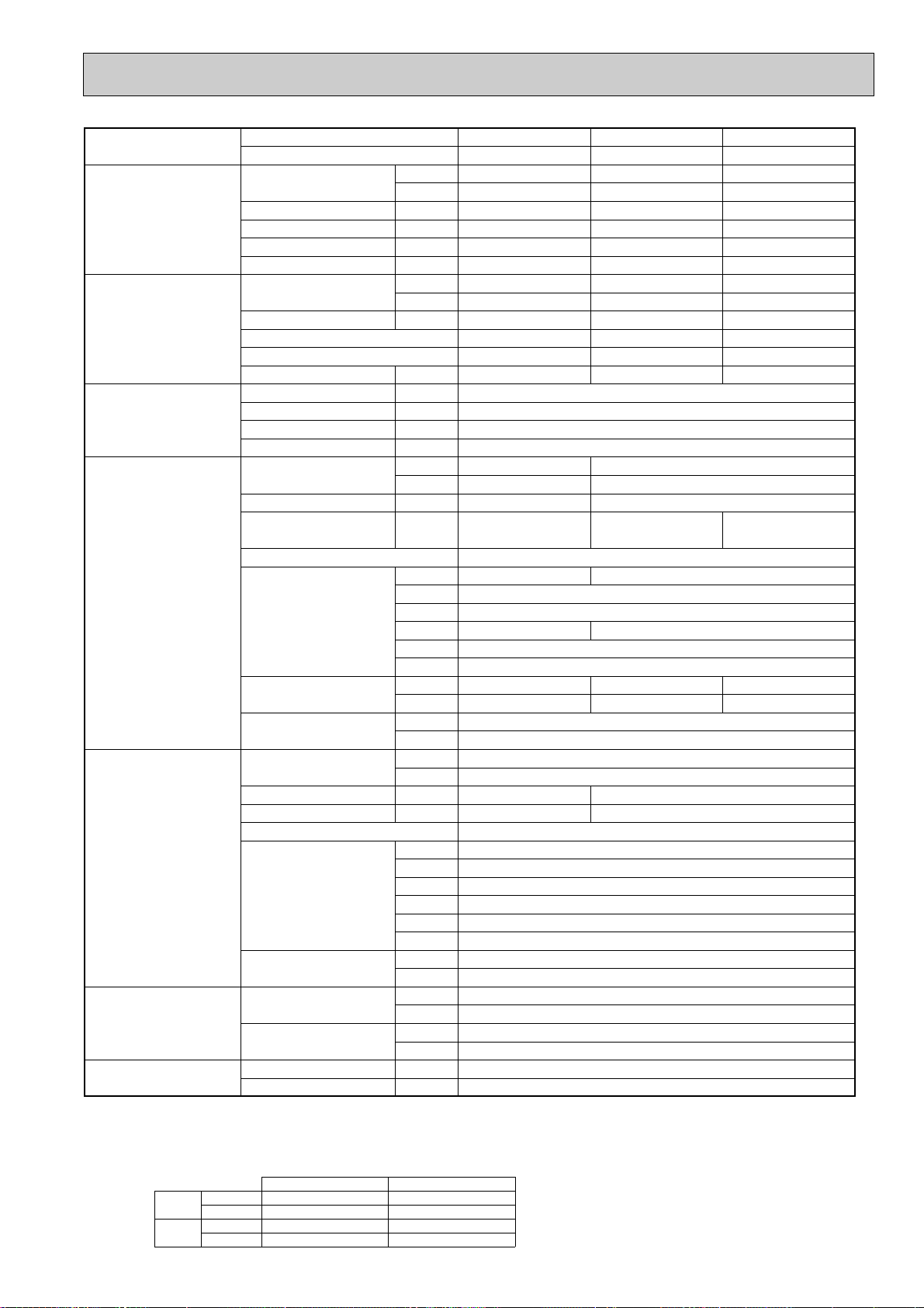
Model name Indoor unit PLA-RP100AA PLA-RP125AA PLA-RP140AA
Outdoor unit PUHZ-RP100VHA PUHZ-RP125VHA PUHZ-RP140VHA
Cooling Capacity Btu/h 34,100 42,700 47,800
kW 10.0(4.9-11.4) 12.5(5.5-14.0) 14.0(5.5-15.3)
Total input kW 3.03 3.89 4.99
EER 3.30 3.21 2.81
Energy label class A A C
SHF 0.77 0.74 0.70
Heating Capacity Btu/h 38,200 47,800 54,600
kW 11.2(4.5-14.0) 14.0(5.0-16.0) 16.0(5.0-18.0)
Total input kW 3.39 4.27 4.91
COP 3.30 3.28 3.26
Energy label class C C C
Booster heater kW - - -
Power supply Phase [ 1
Cycle Hz 50
Voltage V 230
Breaker size A 32 40
Indoor unit Air flow CMM 20-23-26-28 22-25-28-30
(Low-Medium2-Medium1-High) CFM 705-810-920-990 775-880-990-1,060
External pressure Pa 0 0
Sound level dB(A) 33-36-39-41 37-40-43-45
(Low-Medium2-Medium1-High)
External finish (Panel) White Munsell 0.70Y 8.59/0.97
Dimension W : mm 840 (950)
Unit (Panel) D : mm 840 (950)
H : mm 298 (30)
W : inch 33-1/16 (37-3/8)
D : inch 33-1/16 (37-3/8)
H : inch 11-3/4 (1-3/16)
Weight kg 30 (5) 32 (5)
Unit (Panel) lbs 66 (11) 71 (11)
Unit drain pipe I.D. mm 32
inch 1-1/4
Outdoor unit Air flow CMM 100
CFM 3,530
Sound level at cooling dB(A) 49 50
Sound level at heating dB(A) 51 52
External finish Ivory Munsell 3Y 7.8/1.1
Dimension W : mm 950
D : mm 330+30
H : mm 1350
W : inch 37-3/8
D : inch 13 + 1-3/16
H : inch 53-1/8
Weight kg 121
lbs 267
Refrigerant pipe size Gas side O.D. mm 15.88
inch 5/8
Liquid side O.D. mm 9.52
inch 3/8
Refrigerant pipe length Height difference m Max. 30
Length m Max. 75
NOTE: 1. Rating conditions (ISO T1)
Cooling Indoor : D.B. 27: (80˚F) W.B. 19: (66˚F) Outdoor : D.B. 35: (95˚F) W.B. 24: (75˚F)
Heating Indoor: D.B. 20: (68˚F) Outdoor : D.B. 7: (45˚F) W.B. 6: (43˚F)
Refrigerant piping length (one way) : 5m (16ft.)
2. Guaranteed operating range
Cooling
Heating
Upper limit
Lower limit
Upper limit
Lower limit
D.B. 35˚C, W.B. 22.5˚C
D.B. 19˚C, W.B. 15˚C D.B. -5: w
D.B. 28˚C
D.B. 17˚C
Indoor Outdoor
D.B. 46:
D.B. 21:, W.B. 15:
D.B. -20:, W.B. -20:
3. Guaranteed voltage
198~264V, 50Hz
4. Above data based on indicated voltage
Indoor unit Single phase 230V 50Hz
Outdoor unit
w If optional Air protect guide installed. D.B.-15:
Single phase 230V 50Hz
5
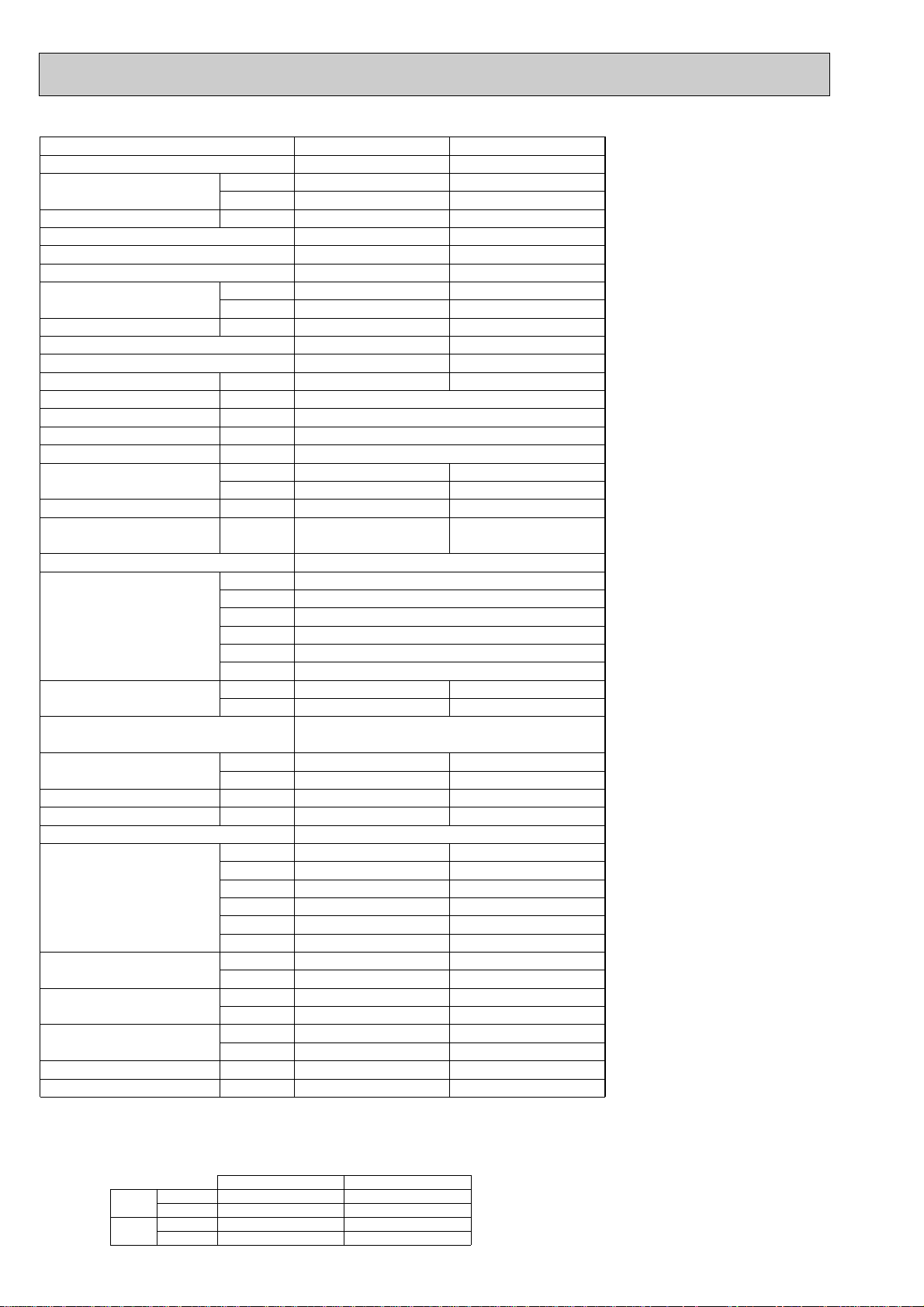
Page 6
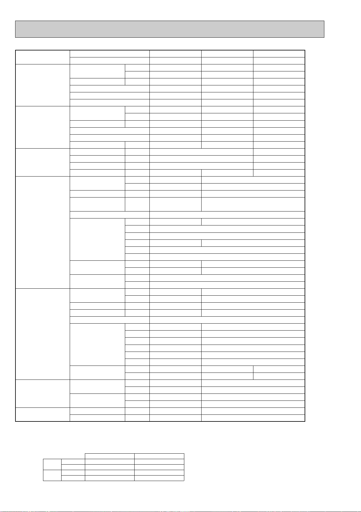
Model name Indoor unit PLA-RP100AA PLA-RP125AA PLA-RP140AA
Outdoor unit PUHZ-RP100YHA PUHZ-RP125YHA PUHZ-RP140YHA
Cooling Capacity Btu/h 34,100 42,700 47,800
kW 10.0(4.9-11.4) 12.5(5.5-14.0) 14.0(5.5-15.3)
Total input kW 3.03 3.89 4.99
EER 3.30 3.21 2.81
Energy label class A A C
SHF 0.77 0.74 0.70
Heating Capacity Btu/h 38,200 47,800 54,600
kW 11.2(4.5-14.0) 14.0(5.0-16.0) 16.0(5.0-18.0)
Total input kW 3.39 4.27 4.91
COP 3.30 3.28 3.26
Energy label class C C C
Booster heater kW - - -
Power supply Phase [ 3
Cycle Hz 50
Voltage V 400
Breaker size A 16
Indoor unit Air flow CMM 20-23-26-28 22-25-28-30
(Low-Medium2-Medium1-High) CFM 705-810-920-990 775-880-990-1,060
External pressure Pa 0 0
Sound level dB(A) 33-36-39-41 37-40-43-45
(Low-Medium2-Medium1-High)
External finish (Panel) White Munsell 0.70Y 8.59/0.97
Dimension W : mm 840 (950)
Unit (Panel) D : mm 840 (950)
H : mm 298 (30)
W : inch 33-1/16 (37-3/8)
D : inch 33-1/16 (37-3/8)
H : inch 11-3/4 (1-3/16)
Weight kg 30 (5) 32 (5)
Unit (Panel) lbs 66 (11) 71 (11)
Unit drain pipe I.D. mm 32
inch 1-1/4
Outdoor unit Air flow CMM 100
CFM 3,530
Sound level at cooling dB(A) 49 50
Sound level at heating dB(A) 51 52
External finish Ivory Munsell 3Y 7.8/1.1
Dimension W : mm 950
D : mm 330+30
H : mm 1350
W : inch 37-3/8
D : inch 13 + 1-3/16
H : inch 53-1/8
Weight kg 135
lbs 298
Refrigerant pipe size Gas side O.D. mm 15.88
inch 5/8
Liquid side O.D. mm 9.52
inch 3/8
Refrigerant pipe length Height difference m Max. 30
Length m Max. 75
NOTE: 1. Rating conditions (ISO T1)
Cooling Indoor : D.B. 27: (80˚F) W.B. 19: (66˚F) Outdoor : D.B. 35: (95˚F) W.B. 24: (75˚F)
Heating Indoor: D.B. 20: (68˚F) Outdoor : D.B. 7: (45˚F) W.B. 6: (43˚F)
Refrigerant piping length (one way) : 5m (16ft.)
2. Guaranteed operating range
Cooling
Heating
Upper limit
Lower limit
Upper limit
Lower limit
D.B. 35˚C, W.B. 22.5˚C
D.B. 19˚C, W.B. 15˚C D.B. -5˚C w
D.B. 28˚C
D.B. 17˚C
Indoor Outdoor
D.B. 46˚C
D.B. 21˚C, W.B. 15˚C
D.B. -20˚C, W.B. -20˚C
3. Guaranteed voltage
Indoor unit 198~264V, 50Hz
Outdoor unit
4. Above data based on indicated voltage
Indoor unit Single phase 230V 50Hz
Outdoor unit
w If optional Air protect guide installed. D.B.-15:
342~457V, 50Hz
3 phase 400V 50Hz
6
Page 7
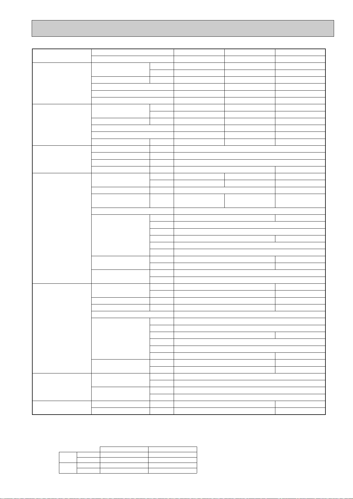
2-2. CEILING-CONCEALED TYPE
Model name Indoor unit PEAD-RP35EA PEAD-RP50EA
Outdoor unit PUHZ-RP35VHA PUHZ-RP50VHA
Cooling Capacity Btu/h 12,300 16,700
kW 3.6(1.6-4.5) 4.9(2.3-5.6)
Total input kW 1.12 1.52
EER 3.21 3.22
Energy label class A A
SHF 0.88 0.82
Heating Capacity Btu/h 14,000 20,500
kW 4.1(1.6-5.2) 6.0(2.5-7.3)
Total input kW 1.26 1.65
COP 3.25 3.64
Energy label class C A
Booster heater kW - -
Power supply Phase [ 1
Cycle Hz 50
Voltage V 230
Breaker size A 16
Indoor unit Air flow CMM 11-14 13.5-17
(Low-High) CFM 388-494 476-600
External pressure Pa 30(70)
Sound level dB(A) 34-38 36-40
(Low-High) (70Pa : 36-43) (70Pa : 38-44)
External finish Galvanized sheets
Dimension W : mm 935
D : mm 700
H : mm 295
W : inch 36-13/16
D : inch 27-5/8
H : inch 11-5/8
Weight kg 33 35
lbs 73 77
Unit drain pipe R1(External thread)
Outdoor unit Air flow CMM 35
CFM 1,240
Sound level at cooling dB(A) 44
Sound level at heating dB(A) 46
External finish Ivory Munsell 3Y 7.8/1.1
Dimension W : mm 800
D : mm 330+23
H : mm 600
W : inch 31-1/2
D : inch 13 + 7/8
H : inch 23-5/8
Weight kg 45
lbs 99
Refrigerant pipe size Gas side O.D. mm 12.7
inch 1/2
Liquid side O.D. mm 6.35
inch 1/4
Refrigerant pipe length Height difference m Max. 30
Length m Max. 50
NOTE: 1. Rating conditions (ISO T1)
Cooling Indoor : D.B. 27: (80˚F) W.B. 19: (66˚F) Outdoor : D.B. 35: (95˚F) W.B. 24: (75˚F)
Heating Indoor: D.B. 20: (68˚F) Outdoor : D.B. 7: (45˚F) W.B. 6: (43˚F)
Refrigerant piping length (one way) : 5m (16ft.)
2. Guaranteed operating range
Cooling
Heating
Upper limit
Lower limit
Upper limit
Lower limit
D.B. 35˚C, W.B. 22.5˚C
D.B. 19˚C, W.B. 15˚C D.B. -5˚C w
D.B. 28˚C
D.B. 17˚C
Indoor Outdoor
D.B. 46˚C
D.B. 21˚C, W.B. 15˚C
D.B. -11˚C, W.B. -12˚C
3. Guaranteed voltage
198~264V, 50Hz
4. Above data based on indicated voltage
Indoor unit Single phase 230V 50Hz
Outdoor unit
w If optional Air protect guide installed. D.B.-15:
Single phase 230V 50Hz
7
Page 8
Indoor unit PEAD-RP60EA PEAD-RP71EA
Outdoor unit PUHZ-RP60VHA PUHZ-RP71VHA
Capacity Btu/h 20,500 24,200
kW 6.0(2.7-6.7) 7.1(3.3-8.1)
Total input kW 1.86 2.15
EER 3.23 3.30
Energy label class A A
SHF 0.79 0.83
Capacity Btu/h 23,900 27,300
kW 7.0(2.8-8.2) 8.0(3.5-10.2)
Total input kW 1.90 2.34
COP 3.68 3.42
Energy label class A B
Booster heater kW - Phase [ 1
Cycle Hz 50
Voltage V 230
Breaker size A 25
Air flow CMM 17-21 20-25
(Low-High) CFM 600-741 706-883
External pressure Pa 30(70) 70(130)
Sound level dB(A) 37-41 37-41
(Low-High) (70Pa : 39-46) (130Pa : 40-45)
External finish Galvanized sheets
Dimension W : mm 1175
D : mm 700
H : mm 295
W : inch 46-1/8
D : inch 27-5/8
H : inch 11-5/8
Weight kg 42 44
lbs 92 97
Unit drain pipe R1(External thread)
Air flow CMM 55 55
CFM 1,940 1,940
Sound level at cooling dB(A) 47 47
Sound level at heating dB(A) 48 48
External finish Ivory Munsell 3Y 7.8/1.1
Dimension W : mm 950 950
D : mm 330+30 330+30
H : mm 943 943
W : inch 37-3/8 37-3/8
D : inch 13 + 1-3/16 13 + 1-3/16
H : inch 37-1/8 37-1/8
Weight kg 75 75
lbs 165 165
Gas side O.D. mm 15.88 15.88
inch 5/8 5/8
Liquid side O.D. mm 9.52 9.52
inch 3/8 3/8
Height difference m Max. 30 Max. 30
Length m Max. 50 Max. 50
NOTE: 1. Rating conditions (ISO T1)
Cooling Indoor : D.B. 27: (80˚F) W.B. 19: (66˚F) Outdoor : D.B. 35: (95˚F) W.B. 24: (75˚F)
Heating Indoor: D.B. 20: (68˚F) Outdoor : D.B. 7: (45˚F) W.B. 6: (43˚F)
Refrigerant piping length (one way) : 5m (16ft.)
2. Guaranteed operating range
Cooling
Heating
Upper limit
Lower limit
Upper limit
Lower limit
D.B. 35˚C, W.B. 22.5˚C
D.B. 19˚C, W.B. 15˚C D.B. -5˚C w
D.B. 28˚C
D.B. 17˚C
Indoor Outdoor
D.B. 46˚C
D.B. 21˚C, W.B. 15˚C
D.B. -11˚C, W.B. -12˚C
3. Guaranteed voltage
198~264V, 50Hz
4. Above data based on indicated voltage
Indoor unit Single phase 230V 50Hz
Outdoor unit
w If optional Air protect guide installed. D.B.-15:
8
Single phase 230V 50Hz
Page 9
Model name Indoor unit PEAD-RP100EA PEAD-RP125EA PEAD-RP140EA
Outdoor unit PUHZ-RP100VHA PUHZ-RP125VHA PUHZ-RP140VHA
Cooling Capacity Btu/h 34,100 42,700 47,800
kW 10.0(4.9-11.4) 12.5(5.5-14.0) 14.0(5.5-15.3)
Total input kW 3.08 3.69 4.91
EER 3.25 3.39 2.85
Energy label class A A C
SHF 0.83 0.82 0.82
Heating Capacity Btu/h 38,200 47,800 54,600
kW 11.2(4.5-14.0) 14.0(5.0-16.0) 16.0(5.0-18.0)
Total input kW 3.48 4.11 4.76
COP 3.22 3.41 3.36
Energy label class C B C
Booster heater kW - - -
Power supply Phase [ 1
Cycle Hz 50
Voltage V 230
Breaker size A 32 40
Indoor unit Air flow CMM 27-34 33.5-42 36.5-46
(Low-High) CFM 953-1200 1183-1483 1288-1624
External pressure Pa 70(130)
Sound level dB(A) 41-46 44-50 46-51
(Low-High) (130Pa : 42-48) (130Pa : 46-52) (130Pa : 47-53)
External finish Galvanized sheets
Dimension W : mm 1415 1715
D : mm 700 740
H : mm 295 325
W : inch 55-11/16 67-1/2
D : inch 27-5/8 29-1/8
H : inch 11-5/8 12-13/16
Weight kg 62 65 70
lbs 136 143 154
Unit drain pipe R1(External thread)
Outdoor unit Air flow CMM 100
CFM 3,530
Sound level at cooling dB(A) 49 50
Sound level at heating dB(A) 51 52
External finish Ivory Munsell 3Y 7.8/1.1
Dimension W : mm 950
D : mm 330+30
H : mm 1350
W : inch 37-3/8
D : inch 13 + 1-3/16
H : inch 53-1/8
Weight kg 121
lbs 267
Refrigerant pipe size Gas side O.D. mm 15.88
inch 5/8
Liquid side O.D. mm 9.52
inch 3/8
Refrigerant pipe length Height difference m Max. 30
Length m Max. 75
NOTE: 1. Rating conditions (ISO T1)
Cooling Indoor : D.B. 27: (80˚F) W.B. 19: (66˚F) Outdoor : D.B. 35: (95˚F) W.B. 24: (75˚F)
Heating Indoor: D.B. 20: (68˚F) Outdoor : D.B. 7: (45˚F) W.B. 6: (43˚F)
Refrigerant piping length (one way) : 5m (16ft.)
2. Guaranteed operating range
Cooling
Heating
Upper limit
Lower limit
Upper limit
Lower limit
D.B. 35˚C, W.B. 22.5˚C
D.B. 19˚C, W.B. 15˚C D.B. -5: w
D.B. 28˚C
D.B. 17˚C
Indoor Outdoor
D.B. 46:
D.B. 21:, W.B. 15:
D.B. -20:, W.B. -20:
3. Guaranteed voltage
198~264V, 50Hz
4. Above data based on indicated voltage
Indoor unit Single phase 230V 50Hz
Outdoor unit
w If optional Air protect guide installed. D.B.-15:
Single phase 230V 50Hz
9
Page 10
Model name Indoor unit PEAD-RP100EA PEAD-RP125EA PEAD-RP140EA
Outdoor unit PUHZ-RP100YHA PUHZ-RP125YHA PUHZ-RP140YHA
Cooling Capacity Btu/h 34,100 42,700 47,800
kW 10.0(4.9-11.4) 12.5(5.5-14.0) 14.0(5.5-15.3)
Total input kW 3.08 3.69 4.91
EER 3.25 3.39 2.85
Energy label class A A C
SHF 0.83 0.82 0.82
Heating Capacity Btu/h 38,200 47,800 54,600
kW 11.2(4.5-14.0) 14.0(5.0-16.0) 16.0(5.0-18.0)
Total input kW 3.48 4.11 4.76
COP 3.22 3.41 3.36
Energy label class C B C
Booster heater kW - - -
Power supply Phase [ 3
Cycle Hz 50
Voltage V 400
Breaker size A 16
Indoor unit Air flow CMM 27-34 33.5-42 36.5-46
(Low-High) CFM 953-1200 1183-1483 1288-1624
External pressure Pa 70(130)
Sound level dB(A) 41-46 44-50 46-51
(Low-High) (130Pa : 42-48) (130Pa : 46-52) (130Pa : 47-53)
External finish Galvanized sheets
Dimension W : mm 1415 1715
D : mm 700 740
H : mm 295 325
W : inch 55-11/16 67-1/2
D : inch 27-5/8 29-1/8
H : inch 11-5/8 12-13/16
Weight kg 62 65 70
lbs 136 143 154
Unit drain pipe R1(External thread)
Outdoor unit Air flow CMM 100
CFM 3,530
Sound level at cooling dB(A) 49 50
Sound level at heating dB(A) 51 52
External finish Ivory Munsell 3Y 7.8/1.1
Dimension W : mm 950
D : mm 330+30
H : mm 1350
W : inch 37-3/8
D : inch 13 + 1-3/16
H : inch 53-1/8
Weight kg 135
lbs 298
Refrigerant pipe size Gas side O.D. mm 15.88
inch 5/8
Liquid side O.D. mm 9.52
inch 3/8
Refrigerant pipe length Height difference m Max. 30
Length m Max. 75
NOTE: 1. Rating conditions (ISO T1)
Cooling Indoor : D.B. 27: (80˚F) W.B. 19: (66˚F) Outdoor : D.B. 35: (95˚F) W.B. 24: (75˚F)
Heating Indoor: D.B. 20: (68˚F) Outdoor : D.B. 7: (45˚F) W.B. 6: (43˚F)
Refrigerant piping length (one way) : 5m (16ft.)
2. Guaranteed operating range
Cooling
Heating
Upper limit
Lower limit
Upper limit
Lower limit
D.B. 35˚C, W.B. 22.5˚C
D.B. 19˚C, W.B. 15˚C D.B. -5˚C w
D.B. 28˚C
D.B. 17˚C
Indoor Outdoor
D.B. 46˚C
D.B. 21˚C, W.B. 15˚C
D.B. -20˚C, W.B. -20˚C
3. Guaranteed voltage
Indoor unit 198~264V, 50Hz
Outdoor unit
4. Above data based on indicated voltage
Indoor unit Single phase 230V 50Hz
Outdoor unit
w If optional Air protect guide installed. D.B.-15:
342~457V, 50Hz
3 phase 400V 50Hz
10
Page 11
,
Model name Indoor unit PEAD-RP60GA PEAD-RP71GA PEAD-RP100GA
Outdoor unit PUHZ-RP60VHA PUHZ-RP71VHA PUHZ-RP100VHA
Cooling Capacity Btu/h 20,500 24,200 34,100
kW 6.0(2.7-6.7) 7.1(3.3-8.1) 10.0(4.9-11.4)
Total input kW 1.68 2.15 3.08
EER 3.57 3.30 3.25
Energy label class A A A
SHF 0.88 0.83 0.83
Heating Capacity Btu/h 23,900 27,300 38,200
kW 7.0(2.8-8.2) 8.0(3.5-10.2) 11.2(4.5-14.0)
Total input kW 1.77 2.34 3.48
COP 3.95 3.42 3.22
Energy label class A B C
Booster heater kW - - -
Power supply Phase [ 1
Cycle Hz 50
Voltage V 230
Breaker size A 25 32
Indoor unit Air flow CMM 16.5-21 20-25 26.5-33
(Low-High) CFM 582-741 706-883 935-1165
External pressure Pa 10/50/70 10/50/70
Sound level dB(A) 33-37/35-40/36-42 35-38/37-41/37-43 40-43/42-45/42-46
(Low-High) (10/50/70Pa) (10/50/70Pa) (10/50/70Pa)
External finish Galvanized sheets
Dimension W : mm 1171 1411
D : mm 740
H : mm 275
W : inch 46-1/8 55-9/16
D : inch 29-1/8
H : inch 10-13/16
Weight kg 42 50
lbs 93 111
Unit drain pipe O.D. mm 32
inch 1-1/4
Outdoor unit Air flow CMM 55 100
CFM 1,940 3,530
Sound level at cooling dB(A) 47 49
Sound level at heating dB(A) 48 51
External finish Ivory Munsell 3Y 7.8/1.1
Dimension W : mm 950
D : mm 330+30
H : mm 943 1350
W : inch 37-3/8
D : inch 13 + 1-3/16
H : inch 37-1/8 53-1/8
Weight kg 75 121
lbs 165 267
Refrigerant pipe size Gas side O.D. mm 15.88
inch 5/8
Liquid side O.D. mm 9.52
inch 3/8
Refrigerant pipe length Height difference m Max. 30 Max. 30
Length m Max. 50 Max. 75
NOTE: 1. Rating conditions (ISO T1)
Cooling Indoor : D.B. 27: (80˚F) W.B. 19: (66˚F) Outdoor : D.B. 35: (95˚F) W.B. 24: (75˚F)
Heating Indoor: D.B. 20: (68˚F) Outdoor : D.B. 7: (45˚F) W.B. 6: (43˚F)
Refrigerant piping length (one way) : 5m (16ft.)
2. Guaranteed operating range
Cooling
Heating
Upper limit
Lower limit
Upper limit
Lower limit
D.B. 35˚C, W.B. 22.5˚C
D.B. 19˚C, W.B. 15˚C D.B. -5˚C w1
D.B. 28˚C
D.B. 17˚C
Indoor Outdoor
D.B. 46˚C
D.B. 21˚C, W.B. 15˚C
D.B. -11˚C, W.B. -12˚C w2
3. Guaranteed voltage
198~264V, 50Hz
4. Above data based on indicated voltage
Indoor unit Single phase 230V 50Hz
Outdoor unit
w1. If optional Air protect guide installed. D.B.-15:
w2. For RP100 D.B. -20:
Single phase 230V 50Hz
W.B. -20:
11
Page 12

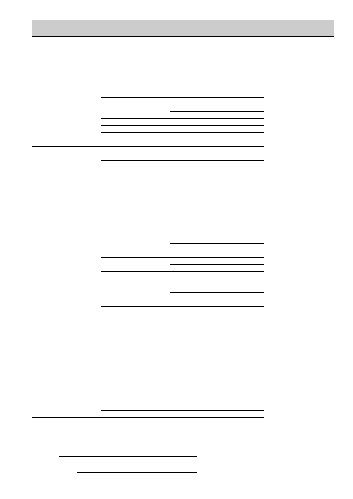
g
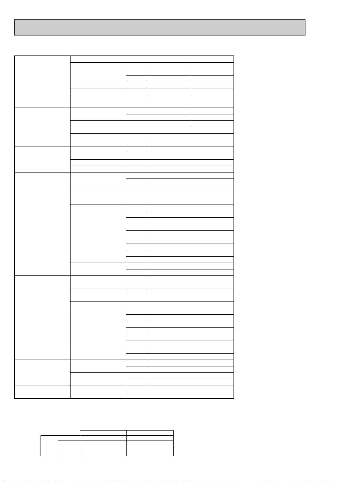
Model name Indoor unit PEAD-RP100GA
Outdoor unit PUHZ-RP100YHA
Cooling Capacity Btu/h 34,100
kW 10.0(4.9-11.4)
Total input kW 3.08
EER 3.25
Energy label class A
SHF 0.83
Heating Capacity Btu/h 38,200
kW 11.2(4.5-14.0)
Total input kW 3.48
COP 3.22
Energy label class C
Booster heater kW -
Power supply Phase [ 3
Cycle Hz 50
Voltage V 400
Breaker size A 16
Indoor unit Air flow CMM 26.5-33
(Low-High) CFM 935-1165
External pressure Pa 10/50/70
Sound level dB(A) 40-43/42-45/42-46
(Low-High) (10/50/70Pa)
External finish Galvanized sheets
Dimension W : mm 1411
D : mm 740
H : mm 275
W : inch 55-9/16
D : inch 29-1/8
H : inch 10-13/16
Weight kg 50
lbs 111
Unit drain pipe O.D. mm 32
inch 1-1/4
Outdoor unit Air flow CMM 100
CFM 3,530
Sound level at cooling dB(A) 49
Sound level at heating dB(A) 51
External finish Ivory Munsell 3Y 7.8/1.1
Dimension W : mm 943
D : mm 330+30
H : mm 1350
W : inch 37-3/8
D : inch 13 + 1-3/16
H : inch 53-1/8
Weight kg 135
lbs 298
Refrigerant pipe size Gas side O.D. mm 15.88
inch 5/8
Liquid side O.D. mm 9.52
inch 3/8
Refrigerant pipe length Height difference m Max. 30
Length m Max. 75
NOTE: 1. Rating conditions (ISO T1)
Cooling Indoor : D.B. 27: (80˚F) W.B. 19: (66˚F) Outdoor : D.B. 35: (95˚F) W.B. 24: (75˚F)
Heating Indoor: D.B. 20: (68˚F) Outdoor : D.B. 7: (45˚F) W.B. 6: (43˚F)
Refrigerant piping length (one way) : 5m (16ft.)
2. Guaranteed operating range
Cooling
Heating
Upper limit
Lower limit
Upper limit
Lower limit
D.B. 35˚C, W.B. 22.5˚C
D.B. 19˚C, W.B. 15˚C D.B. -5: w
D.B. 28˚C
D.B. 17˚C
Indoor Outdoor
D.B. 46:
D.B. 21:, W.B. 15:
D.B. -20:, W.B. -20:
3. Guaranteed voltage
198~264V, 50Hz
4. Above data based on indicated voltage
Indoor unit Single phase 230V 50Hz
Outdoor unit
w If optional Air protect
12
Single phase 230V 50Hz
uide installed. D.B.-15:
Page 13
g
Model name Indoor unit PEA-RP71EA
Outdoor unit PUHZ-RP71VHA
Cooling Capacity Btu/h 24,200
kW 7.1(3.3-8.1)
Total input kW 2.48
EER 2.86
SRI 3.87
SHF 0.82
Heating Capacity Btu/h 27,300
kW 8.0(3.5-10.2)
Total input kW 2.47
COP 3.24
SRI 4.13
Booster heater kW -
Power supply Phase [ 1
Cycle Hz 50
Voltage V 230
Breaker size A 25
Indoor unit Air flow CMM 22-27
(Low-High) CFM 780-955
External pressure Pa 125
Sound level dB(A) 52-55
(Low-High)
External finish Galvanized sheets
Dimension W : mm 785
D : mm 690
H : mm 428
W : inch 31
D : inch 27-1/16
H : inch 16-7/8
Weight kg 46
lbs 101
Unit drain pipe R1(External thread)
Outdoor unit Air flow CMM 55
CFM 1,940
Sound level at cooling dB(A) 47
Sound level at heating dB(A) 48
External finish Ivory Munsell 3Y 7.8/1.1
Dimension W : mm 950
D : mm 330+30
H : mm 943
W : inch 37-3/8
D : inch 13 + 1-3/16
H : inch 37-1/8
Weight kg 75
lbs 165
Refrigerant pipe size Gas side O.D. mm 15.88
inch 5/8
Liquid side O.D. mm 9.52
inch 3/8
Refrigerant pipe length Height difference m Max. 30
Length m Max. 50
NOTE: 1. Rating conditions (ISO T1)
Cooling Indoor : D.B. 27: (80˚F) W.B. 19: (66˚F) Outdoor : D.B. 35: (95˚F) W.B. 24: (75˚F)
Heating Indoor: D.B. 20: (68˚F) Outdoor : D.B. 7: (45˚F) W.B. 6: (43˚F)
Refrigerant piping length (one way) : 5m (16ft.)
2. Guaranteed operating range
Cooling
Heating
Upper limit
Lower limit
Upper limit
Lower limit
D.B. 35˚C, W.B. 22.5˚C
D.B. 19˚C, W.B. 15˚C D.B. -5˚C w
D.B. 28˚C
D.B. 17˚C
Indoor Outdoor
D.B. 46˚C
D.B. 21˚C, W.B. 15˚C
D.B. -11˚C, W.B. -12˚C
3. Guaranteed voltage
198~264V, 50Hz
4. Above data based on indicated voltage
Indoor unit Single phase 230V 50Hz
Outdoor unit
w If optional Air protect
13
Single phase 230V 50Hz
uide installed. D.B.-15:
Page 14
Model name Indoor unit PEA-RP100EA PEA-RP125EA PEA-RP140EA
Outdoor unit PUHZ-RP100VHA PUHZ-RP125VHA PUHZ-RP140VHA
Cooling Capacity Btu/h 34,100 42,700 47,800
kW 10.0(4.9-11.4) 12.5(5.5-14.0) 14.0(5.5-15.3)
Total input kW 3.25 4.42 5.03
EER 3.08 2.83 2.78
SRI 4.60 3.77 3.60
SHF 0.82 0.81 0.89
Heating Capacity Btu/h 38,200 47,800 54,600
kW 11.2(4.5-14.0) 14.0(5.0-16.0) 16.0(5.0-18.0)
Total input kW 3.2 4.30 4.73
COP 3.50 3.26 3.38
SRI 5.00 4.20 4.60
Booster heater kW - - -
Power supply Phase [ 1
Cycle Hz 50
Voltage V 230
Breaker size A 32 40
Indoor unit Air flow CMM 27-34 34-42 48-60
(Low-High) CFM 955-1200 1200-1480 1695-2120
External pressure Pa 125
Sound level dB(A) 54-58 51-55
(Low-High)
External finish Galvanized sheets
Dimension W : mm 1055 1255 1415
D : mm 690
H : mm 428
W : inch 41-1/2 49-7/16 55-3/4
D : inch 27-1/16
H : inch 16-7/8
Weight kg 58 72 73
lbs 128 159 161
Unit drain pipe R1(External thread)
Outdoor unit Air flow CMM 100
CFM 3,530
Sound level at cooling dB(A) 49 50
Sound level at heating dB(A) 51 52
External finish Ivory Munsell 3Y 7.8/1.1
Dimension W : mm 950
D : mm 330+30
H : mm 1350
W : inch 37-3/8
D : inch 13 + 1-3/16
H : inch 53-1/8
Weight kg 121
lbs 267
Refrigerant pipe size Gas side O.D. mm 15.88
inch 5/8
Liquid side O.D. mm 9.52
inch 3/8
Refrigerant pipe length Height difference m Max. 30
Length m Max. 75
NOTE: 1. Rating conditions (ISO T1)
Cooling Indoor : D.B. 27: (80˚F) W.B. 19: (66˚F) Outdoor : D.B. 35: (95˚F) W.B. 24: (75˚F)
Heating Indoor: D.B. 20: (68˚F) Outdoor : D.B. 7: (45˚F) W.B. 6: (43˚F)
Refrigerant piping length (one way) : 5m (16ft.)
2. Guaranteed operating range
Cooling
Heating
Upper limit
Lower limit
Upper limit
Lower limit
D.B. 35˚C, W.B. 22.5˚C
D.B. 19˚C, W.B. 15˚C D.B. -5: w
D.B. 28˚C
D.B. 17˚C
Indoor Outdoor
D.B. 46:
D.B. 21:, W.B. 15:
D.B. -20:, W.B. -20:
3. Guaranteed voltage
198~264V, 50Hz
4. Above data based on indicated voltage
Indoor unit Single phase 230V 50Hz
Outdoor unit
w If optional Air protect guide installed. D.B.-15:
Single phase 230V 50Hz
14
Page 15

NOTE: 1. Rating conditions (ISO T1)
Cooling Indoor : D.B. 27: (80˚F) W.B. 19: (66˚F) Outdoor : D.B. 35: (95˚F) W.B. 24: (75˚F)
Heating Indoor: D.B. 20: (68˚F) Outdoor : D.B. 7: (45˚F) W.B. 6: (43˚F)
Refrigerant piping length (one way) : 5m (16ft.)
2. Guaranteed operating range
Indoor Outdoor
Cooling
Upper limit
D.B. 35˚C, W.B. 22.5˚C
D.B. 46:
Lower limit
D.B. 19˚C, W.B. 15˚C D.B. -5: w
Heating
Upper limit
D.B. 28˚C
D.B. 21:, W.B. 15:
Lower limit
D.B. 17˚C
D.B. -20:, W.B. -20:
4. Above data based on indicated voltage
w If optional Air protect guide installed. D.B.-15:
Indoor unit Single phase 230V 50Hz
Single phase 230V 50Hz
Outdoor unit
3. Guaranteed voltage
198~264V, 50Hz
Model name Indoor unit PEH-RP200MYA PEH-RP250MYA
Outdoor unit PUHZ-RP200YHA PUHZ-RP250YHA
Cooling Capacity Btu/h 64,800 75,000
kW 19.0(10.0-22.4) 22.0(12.5-28.0)
Total input kW 7.28 8.43
EER 2.61 2.61
Energy label class D D
SHF 0.75 0.82
Heating Capacity Btu/h 76,400 92,100
kW 22.4(10.0-25.0) 27.0(15.7-31.5)
Total input kW 6.98 8.41
COP 3.21 3.21
Energy label class C C
Booster heater kW - -
Power supply Phase [ 3
Cycle Hz 50
Voltage V 400
Breaker size A 32
Indoor unit Air flow CMM 60 80
CFM 2120 2825
External pressure Pa 50/150
Sound level dB(A) 49 53
(50Pa) (50Pa)
External finish Galvanizing
Dimension W : mm 1380 1580
D : mm 650
H : mm 428
W : inch 54-5/16 62-3/16
D : inch 25-9/16
H : inch 16-7/8
Weight kg 70 80
lbs 154 176
Unit drain pipe RC1
Outdoor unit Air flow CMM 150
CFM 5,300
Sound level at cooling dB(A) 55 58
Sound level at heating dB(A) 56 58
External finish Ivory Munsell 3Y 7.8/1.1
Dimension W : mm 900
D : mm 750
H : mm 1798
W : inch 35-7/16
D : inch 29-17/32
H : inch 70-25/32
Weight kg 198
lbs 436
Refrigerant pipe size Gas side O.D. mm 25.4 28.58
inch 1 1-1/8
Liquid side O.D. mm 9.52 12.7
inch 3/8 1/2
Refrigerant pipe length Height difference m Max. 40
Length m Max. 120
15
Page 16
2-3. WALL-MOUNTED TYPE
Model name Indoor unit PKA-RP35GAL PKA-RP50GAL
Outdoor unit PUHZ-RP35VHA PUHZ-RP50VHA
Cooling Capacity Btu/h 12,300 15,700
kW 3.6(1.6-4.5) 4.6(2.3-5.4)
Total input kW 1.03 1.63
EER 3.50 2.82
Energy label class A C
SHF 0.84 0.74
Heating Capacity Btu/h 14,000 15,400
kW 4.1(1.6-5.2) 4.5(2.5-6.2)
Total input kW 1.27 1.40
COP 3.23 3.21
Energy label class C C
Booster heater kW - -
Power supply Phase
Cycle Hz 50
Voltage V 230
Breaker size A 16
Indoor unit Air flow CMM 9-10-11-12
(Low-Medium2-Medium1-High) CFM 320-355-390-425
External pressure Pa 0
Sound level dB(A) 36-38-41-43
(Low-Medium2-Medium1-High)
External finish White Munsell 0.70Y 8.59/0.97
Dimension W : mm 990
Weight kg 16
Unit drain pipe O.D. mm 20
Outdoor unit Air flow CMM 35
Sound level at cooling dB(A) 44
Sound level at heating dB(A) 46
External finish Ivory Munsell 3Y 7.8/1.1
Dimension W : mm 800
Weight kg 45
Refrigerant pipe size Gas side O.D. mm 12.7
Liquid side O.D. mm 6.35
Refrigerant pipe length Height difference m Max. 30
Length m Max. 50
NOTE: 1. Rating conditions (ISO T1)
Cooling Indoor : D.B. 27: (80˚F) W.B. 19: (66˚F) Outdoor : D.B. 35: (95˚F) W.B. 24: (75˚F)
Heating Indoor: D.B. 20: (68˚F) Outdoor : D.B. 7: (45˚F) W.B. 6: (43˚F)
Refrigerant piping length (one way) : 5m (16ft.)
2. Guaranteed operating range
Indoor Outdoor
Cooling
Heating
Upper limit
Lower limit
Upper limit
Lower limit
D.B. 35˚C, W.B. 22.5˚C
D.B. 19˚C, W.B. 15˚C D.B. -5˚C w
D.B. 28˚C
D.B. 17˚C
[ 1
D : mm 235
H : mm 340
W : inch 39
D : inch 9-1/4
H : inch 13-3/8
lbs 35
inch 13/16
CFM 1,240
D : mm 330+23
H : mm 600
W : inch 31-1/2
D : inch 13 + 7/8
H : inch 23-5/8
lbs 99
inch 1/2
inch 1/4
3. Guaranteed voltage
198~264V, 50Hz
D.B. 46˚C
D.B. 21˚C, W.B. 15˚C
D.B. -11˚C, W.B. -12˚C
4. Above data based on indicated voltage
Indoor unit Single phase 230V 50Hz
Outdoor unit
w If optional Air protect guide installed. D.B.-15:
Single phase 230V 50Hz
16
Page 17
Model name Indoor unit PKA-RP60FAL PKA-RP71FAL PKA-RP100FAL
Outdoor unit PUHZ-RP60VHA PUHZ-RP71VHA PUHZ-RP100VHA
Cooling Capacity Btu/h 20,500 24,200 34,100
kW 6.0(2.7-6.7) 7.1(3.3-8.1) 10.0(4.9-11.4)
Total input kW 1.55 1.98 2.93
EER 3.87 3.59 3.41
Energy label class A A A
SHF 0.83 0.77 0.77
Heating Capacity Btu/h 23,900 27,300 38,200
kW 7.0(2.8-8.2) 8.0(3.5-10.2) 11.2(4.5-14.0)
Total input kW 2.01 2.40 3.25
COP 3.48 3.33 3.45
Energy label class B C B
Booster heater kW - - -
Power supply Phase [ 1
Cycle Hz 50
Voltage V 230
Breaker size A 25 32
Indoor unit Air flow CMM 15-20 22-28
(Low-High) CFM 530-705 780-990
External pressure Pa 0
Sound level dB(A) 39-45 41-46
(Low-High)
External finish Munsell 3.4Y 7.7/0.8
Dimension W : mm 1400 1680
D : mm 235
H : mm 340
W : inch 55-1/8 66-1/8
D : inch 9-1/4
H : inch 13-3/8
Weight kg 24 28
lbs 53 62
Unit drain pipe O.D. mm 20
inch 13/16
Outdoor unit Air flow CMM 55 100
CFM 1,940 3,530
Sound level at cooling dB(A) 47 49
Sound level at heating dB(A) 48 51
External finish Ivory Munsell 3Y 7.8/1.1
Dimension W : mm 950
D : mm 330+30
H : mm 943 1350
W : inch 37-3/8
D : inch 13 + 1-3/16
H : inch 37-1/8 53-1/8
Weight kg 75 121
lbs 165 267
Refrigerant pipe size Gas side O.D. mm 15.88
inch 5/8
Liquid side O.D. mm 9.52
inch 3/8
Refrigerant pipe length Height difference m Max. 30 Max. 30
Length m Max. 50 Max. 75
NOTE: 1. Rating conditions (ISO T1)
Cooling Indoor : D.B. 27: (80˚F) W.B. 19: (66˚F) Outdoor : D.B. 35: (95˚F) W.B. 24: (75˚F)
Heating Indoor: D.B. 20: (68˚F) Outdoor : D.B. 7: (45˚F) W.B. 6: (43˚F)
Refrigerant piping length (one way) : 5m (16ft.)
2. Guaranteed operating range
Cooling
Heating
Upper limit
Lower limit
Upper limit
Lower limit
D.B. 35˚C, W.B. 22.5˚C
D.B. 19˚C, W.B. 15˚C D.B. -5˚C w1
D.B. 28˚C
D.B. 17˚C
Indoor Outdoor
D.B. 46˚C
D.B. 21˚C, W.B. 15˚C
D.B. -11˚C, W.B. -12˚C w2
3. Guaranteed voltage
198~264V, 50Hz
4. Above data based on indicated voltage
Indoor unit Single phase 230V 50Hz
Outdoor unit
w1. If optional Air protect guide installed. D.B.-15:
w2. For RP100 D.B. -20:, W.B. -20:
Single phase 230V 50Hz
17
Page 18
Model name Indoor unit PKA-RP100FAL
Outdoor unit PUHZ-RP100YHA
Cooling Capacity Btu/h 34,100
kW 10.0(4.9-11.4)
Total input kW 2.93
EER 3.41
Energy label class A
SHF 0.77
Heating Capacity Btu/h 38,200
kW 11.2(4.5-14.0)
Total input kW 3.25
COP 3.45
Energy label class B
Booster heater kW -
Power supply Phase 3
Cycle Hz
[
50
Voltage V 400
Breaker size A 16
Indoor unit Air flow CMM 22-28
(Low-High) CFM 780-990
External pressure Pa 0
Sound level dB(A) 41-46
(Low-High)
External finish Munsell 3.4Y 7.7/0.8
Dimension W : mm 1680
D : mm 235
H : mm 340
W : inch 66-1/8
D : inch 9-1/4
H : inch 13-3/8
Weight kg 28
lbs 62
Unit drain pipe O.D. mm 20
inch 13/16
Outdoor unit Air flow CMM 100
CFM 3,530
Sound level at cooling dB(A) 49
Sound level at heating dB(A) 51
External finish Ivory Munsell 3Y 7.8/1.1
Dimension W : mm 950
D : mm 330+30
H : mm 1350
W : inch 37-3/8
D : inch 13 + 1-3/16
H : inch 53-1/8
Weight kg 135
lbs 298
Refrigerant pipe size Gas side O.D. mm 15.88
inch 5/8
Liquid side O.D. mm 9.52
inch 3/8
Refrigerant pipe length Height difference m Max. 30
Length m Max. 75
NOTE: 1. Rating conditions (ISO T1)
Cooling Indoor : D.B. 27: (80˚F) W.B. 19: (66˚F) Outdoor : D.B. 35: (95˚F) W.B. 24: (75˚F)
Heating Indoor: D.B. 20: (68˚F) Outdoor : D.B. 7: (45˚F) W.B. 6: (43˚F)
Refrigerant piping length (one way) : 5m (16ft.)
2. Guaranteed operating range
Cooling
Heating
Upper limit
Lower limit
Upper limit
Lower limit
D.B. 35˚C, W.B. 22.5˚C
D.B. 19˚C, W.B. 15˚C D.B. -5: w
D.B. 28˚C
D.B. 17˚C
Indoor Outdoor
D.B. 46:
D.B. 21:, W.B. 15:
D.B. -20:, W.B. -20:
3. Guaranteed voltage
198~264V, 50Hz
4. Above data based on indicated voltage
w If optional Air protect guide installed. D.B.-15:
18
Indoor unit Single phase 230V 50Hz
Outdoor unit
Single phase 230V 50Hz
Page 19
2-4. CEILING-SUSPENDED TYPE
Model name Indoor unit PCA-RP50GA PCA-RP60GA PCA-RP71GA
Outdoor unit PUHZ-RP50VHA PUHZ-RP60VHA PUHZ-RP71VHA
Cooling Capacity Btu/h 16,000 20,500 24,200
kW 4.7(2.3-5.4) 6.0(2.7-6.7) 7.1(3.3-8.1)
Total input kW 1.67 1.63 2.14
EER 2.81 3.68 3.32
Energy label class C A A
SHF 0.76 0.81 0.74
Heating Capacity Btu/h 18,800 23,900 27,300
kW 5.5(2.5-6.6) 7.0(2.8-8.2) 8.0(3.5-10.2)
Total input kW 1.71 2.03 2.43
COP 3.22 3.45 3.29
Energy label class C B C
Booster heater kW - - -
Power supply Phase
Cycle Hz 50
Voltage V 230
Breaker size A 16 25
Indoor unit Air flow CMM 10-11-12-13 14-15-16-18
(Low-Medium2-Medium1-High) CFM 355-390-425-460 495-530-565-635
External pressure Pa 0 0
Sound level dB(A) 37-38-40-42 37-39-41-43
(Low-Medium2-Medium1-High)
External finish White Munsell 0.70Y 8.59/0.97
Dimension W : mm 1000 1310
Weight kg 27 34
Unit drain pipe I.D. mm 26
Outdoor unit Air flow CMM 35 55
Sound level at cooling dB(A) 44 47
Sound level at heating dB(A) 46 48
External finish Ivory Munsell 3Y 7.8/1.1
Dimension W : mm 800 950
Weight kg 45 75
Refrigerant pipe size Gas side O.D. mm 12.7 15.88
Liquid side O.D. mm 6.35 9.52
Refrigerant pipe length Height difference m Max. 30 Max. 30
Length m Max. 50 Max. 50
[ 1
D : mm 680
H : mm 210
W : inch 39-3/8 51-9/16
D : inch 26-3/4
H : inch 8-1/4
lbs 60 75
inch 1
CFM 1,240 1,940
D : mm 330+23 330+30
H : mm 600 943
W : inch 31-1/2 37-3/8
D : inch 13 + 7/8 13 + 1-3/16
H : inch 23-5/8 37-1/8
lbs 99 165
inch 1/2 5/8
inch 1/4 3/8
NOTE: 1. Rating conditions (ISO T1)
Cooling Indoor : D.B. 27: (80˚F) W.B. 19: (66˚F) Outdoor : D.B. 35: (95˚F) W.B. 24: (75˚F)
Heating Indoor: D.B. 20: (68˚F) Outdoor : D.B. 7: (45˚F) W.B. 6: (43˚F)
Refrigerant piping length (one way) : 5m (16ft.)
2. Guaranteed operating range
Cooling
Heating
Upper limit
Lower limit
Upper limit
Lower limit
D.B. 35˚C, W.B. 22.5˚C
D.B. 19˚C, W.B. 15˚C D.B. -5˚C w
D.B. 28˚C
D.B. 17˚C
Indoor Outdoor
D.B. 46˚C
D.B. 21˚C, W.B. 15˚C
D.B. -11˚C, W.B. -12˚C
19
3. Guaranteed voltage
198~264V, 50Hz
4. Above data based on indicated voltage
Indoor unit Single phase 230V 50Hz
Outdoor unit
w If optional Air protect guide installed. D.B.-15:
Single phase 230V 50Hz
Page 20
NOTE: 1. Rating conditions (ISO T1)
Cooling Indoor : D.B. 27: (80˚F) W.B. 19: (66˚F) Outdoor : D.B. 35: (95˚F) W.B. 24: (75˚F)
Heating Indoor: D.B. 20: (68˚F) Outdoor : D.B. 7: (45˚F) W.B. 6: (43˚F)
Refrigerant piping length (one way) : 5m (16ft.)
2. Guaranteed operating range
Indoor Outdoor
Cooling
Upper limit
D.B. 35˚C, W.B. 22.5˚C
D.B. 46:
Lower limit
D.B. 19˚C, W.B. 15˚C D.B. -5: w
Heating
Upper limit
D.B. 28˚C
D.B. 21:, W.B. 15:
Lower limit
D.B. 17˚C
D.B. -20:, W.B. -20:
4. Above data based on indicated voltage
w If optional Air protect guide installed. D.B.-15:
Indoor unit Single phase 230V 50Hz
Single phase 230V 50Hz
Outdoor unit
3. Guaranteed voltage
198~264V, 50Hz
Model name Indoor unit PCA-RP100GA PCA-RP125GA PCA-RP140GA
Outdoor unit PUHZ-RP100VHA PUHZ-RP125VHA PUHZ-RP140VHA
Cooling Capacity Btu/h 34,100 42,700 47,800
kW 10.0(4.9-11.4) 12.5(5.5-14.0) 14.0(5.5-15.3)
Total input kW 2.92 3.89 4.96
EER 3.42 3.21 2.82
Energy label class A A C
SHF 0.75 0.77 0.74
Heating Capacity Btu/h 38,200 47,800 54,600
kW 11.2(4.5-14.0) 14.0(5.0-16.0) 16.0(5.0-18.0)
Total input kW 3.26 4.34 4.60
COP 3.44 3.23 3.48
Energy label class B C B
Booster heater kW - - -
Power supply Phase [ 1
Cycle Hz 50
Voltage V 230
Breaker size A 32 40
Indoor unit Air flow CMM 20-21-23-25 27-30-32-34
(Low-Medium2-Medium1-High) CFM 705-840-810-885 955-1060-1130-1200
External pressure Pa 0 0
Sound level dB(A) 40-41-43-45 41-43-45-46 42-44-46-48
(Low-Medium2-Medium1-High)
External finish White Munsell 0.70Y 8.59/0.97
Dimension W : mm 1310 1620
D : mm 680
H : mm 270
W : inch 51-9/16 63-3/4
D : inch 26-3/4
H : inch 10-5/8
Weight kg 37 43 45
lbs 82 95 99
Unit drain pipe I.D. mm 26
inch 1
Outdoor unit Air flow CMM 100
CFM 3,530
Sound level at cooling dB(A) 49 50
Sound level at heating dB(A) 51 52
External finish Ivory Munsell 3Y 7.8/1.1
Dimension W : mm 950
D : mm 330+30
H : mm 1350
W : inch 37-3/8
D : inch 13 + 1-3/16
H : inch 53-1/8
Weight kg 121
lbs 267
Refrigerant pipe size Gas side O.D. mm 15.88
inch 5/8
Liquid side O.D. mm 9.52
inch 3/8
Refrigerant pipe length Height difference m Max. 30
Length m Max. 75
20
Page 21
Model name Indoor unit PCA-RP100GA PCA-RP125GA PCA-RP140GA
Outdoor unit PUHZ-RP100YHA PUHZ-RP125YHA PUHZ-RP140YHA
Cooling Capacity Btu/h 34,100 42,700 47,800
kW 10.0(4.9-11.4) 12.5(5.5-14.0) 14.0(5.5-15.3)
Total input kW 2.92 3.89 4.96
EER 3.42 3.21 2.82
Energy label class A A C
SHF 0.75 0.77 0.74
Heating Capacity Btu/h 38,200 47,800 54,600
kW 11.2(4.5-14.0) 14.0(5.0-16.0) 16.0(5.0-18.0)
Total input kW 3.26 4.34 4.60
COP 3.44 3.23 3.48
Energy label class B C B
Booster heater kW - - -
Power supply Phase [ 3
Cycle Hz 50
Voltage V 400
Breaker size A 16
Indoor unit Air flow CMM 20-21-23-25 27-30-32-34
(Low-Medium2-Medium1-High) CFM 705-840-810-885 955-1060-1130-1200
External pressure Pa 0 0
Sound level dB(A) 40-41-43-45 41-43-45-46 42-44-46-48
(Low-Medium2-Medium1-High)
External finish White Munsell 0.70Y 8.59/0.97
Dimension W : mm 1310 1620
D : mm 680
H : mm 270
W : inch 51-9/16 63-3/4
D : inch 26-3/4
H : inch 10-5/8
Weight kg 37 43 45
lbs 82 95 99
Unit drain pipe I.D. mm 26
inch 1
Outdoor unit Air flow CMM 100
CFM 3,530
Sound level at cooling dB(A) 49 50
Sound level at heating dB(A) 51 52
External finish Ivory Munsell 3Y 7.8/1.1
Dimension W : mm 950
D : mm 330+30
H : mm 1350
W : inch 37-3/8
D : inch 13 + 1-3/16
H : inch 53-1/8
Weight kg 135
lbs 298
Refrigerant pipe size Gas side O.D. mm 15.88
inch 5/8
Liquid side O.D. mm 9.52
inch 3/8
Refrigerant pipe length Height difference m Max. 30
Length m Max. 75
NOTE: 1. Rating conditions (ISO T1)
Cooling Indoor : D.B. 27: (80˚F) W.B. 19: (66˚F) Outdoor : D.B. 35: (95˚F) W.B. 24: (75˚F)
Heating Indoor: D.B. 20: (68˚F) Outdoor : D.B. 7: (45˚F) W.B. 6: (43˚F)
Refrigerant piping length (one way) : 5m (16ft.)
2. Guaranteed operating range
Cooling
Heating
Upper limit
Lower limit
Upper limit
Lower limit
D.B. 35˚C, W.B. 22.5˚C
D.B. 19˚C, W.B. 15˚C D.B. -5: w
D.B. 28˚C
D.B. 17˚C
Indoor Outdoor
D.B. 46:
D.B. 21:, W.B. 15:
D.B. -20:, W.B. -20:
3. Guaranteed voltage
198~264V, 50Hz
4. Above data based on indicated voltage
Indoor unit Single phase 230V 50Hz
Outdoor unit
w If optional Air protect guide installed. D.B.-15:
Single phase 230V 50Hz
21
Page 22
NOTE: 1. Rating conditions (ISO T1)
Cooling Indoor : D.B. 27: (80˚F) W.B. 19: (66˚F) Outdoor : D.B. 35: (95˚F) W.B. 24: (75˚F)
Heating Indoor: D.B. 20: (68˚F) Outdoor : D.B. 7: (45˚F) W.B. 6: (43˚F)
Refrigerant piping length (one way) : 5m (16ft.)
2. Guaranteed operating range
Indoor Outdoor
Cooling
Upper limit
D.B. 35˚C, W.B. 22.5˚C
D.B. 46˚C
Lower limit
D.B. 19˚C, W.B. 15˚C D.B. -5˚C w1
Heating
Upper limit
D.B. 28˚C
D.B. 21˚C, W.B. 15˚C
Lower limit
D.B. 17˚C
D.B. -11˚C, W.B. -12˚C w2
4. Above data based on indicated voltage
w1. If optional Air protect guide installed. D.B.-15:
w2. For RP125 D.B. -20:, W.B. -20:
Indoor unit Single phase 230V 50Hz
Single phase 230V 50Hz
Outdoor unit
3. Guaranteed voltage
198~264V, 50Hz
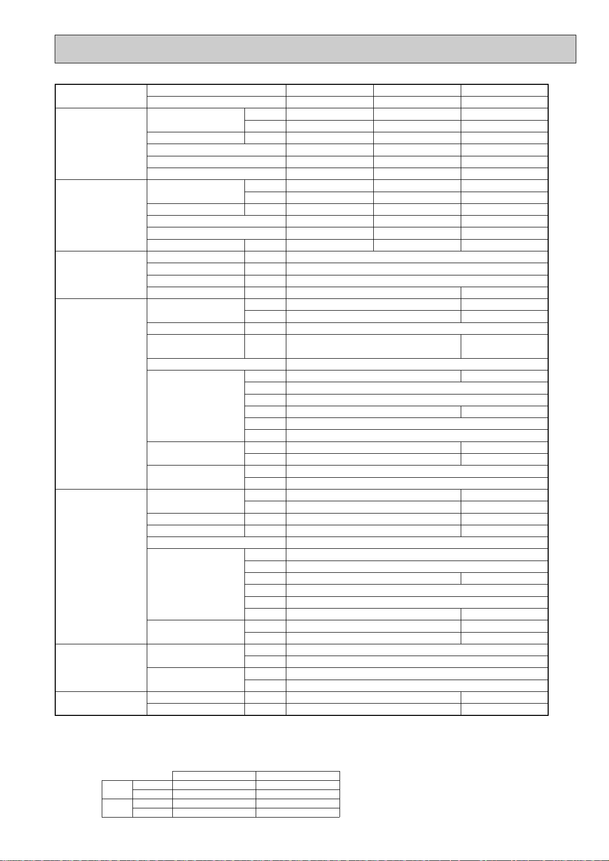
Model name Indoor unit PCA-RP71HA PCA-RP125HA PCA-RP125HA
Outdoor unit PUHZ-RP71VHA PUHZ-RP125VHA PUHZ-RP125YHA
Cooling Capacity Btu/h 24,200 42,700 42,700
kW 7.1(3.3-8.1) 12.5(5.5-14.0) 12.5(5.5-14.0)
Total input kW 2.21 4.15 4.15
EER 3.21 3.01 3.01
Energy label class A B B
SHF 0.74 0.77 0.77
Heating Capacity Btu/h 27,300 47,800 47,800
kW 8.0(3.5-10.2) 14.0(5.0-16.0) 14.0(5.0-16.0)
Total input kW 2.49 4.25 4.25
COP 3.21 3.29 3.29
Energy label class C C C
Booster heater kW - - -
Power supply Phase [ 13
Cycle Hz 50 50
Voltage V 230 400
Breaker size A 322525 16
Indoor unit Air flow CMM 17-19 30-38
(Low-High) CFM 600-670 1060-1350
External pressure Pa 0 0
Sound level dB(A) 34-38 44-50
(Low-High)
External finish Stainless steel
Dimension W : mm 1136 1520
D : mm 650
H : mm 280
W : inch 44-3/4 59-7/8
D : inch 25-5/8
H : inch 11
Weight kg 41 56
lbs 90 124
Unit drain pipe I.D. mm 26
inch 1
Outdoor unit Air flow CMM 55 100
CFM 1,940 3,530
Sound level at cooling dB(A) 47 50
Sound level at heating dB(A) 48 52
External finish Ivory Munsell 3Y 7.8/1.1
Dimension W : mm 950 950
D : mm 330+30 330+30
H : mm 943 1350
W : inch 37-3/8 37-3/8
D : inch 13 + 1-3/16 13 + 1-3/16
H : inch 37-1/8 53-1/8
Weight kg 75 121 135
lbs 165 267 298
Refrigerant pipe size Gas side O.D. mm 15.88 15.88
inch 5/8 5/8
Liquid side O.D. mm 9.52 9.52
inch 3/8 3/8
Refrigerant pipe length Height difference m Max. 30 Max. 30
Length m Max. 50 Max. 75
22
Page 23
2-5. FLOOR STANDING TYPE
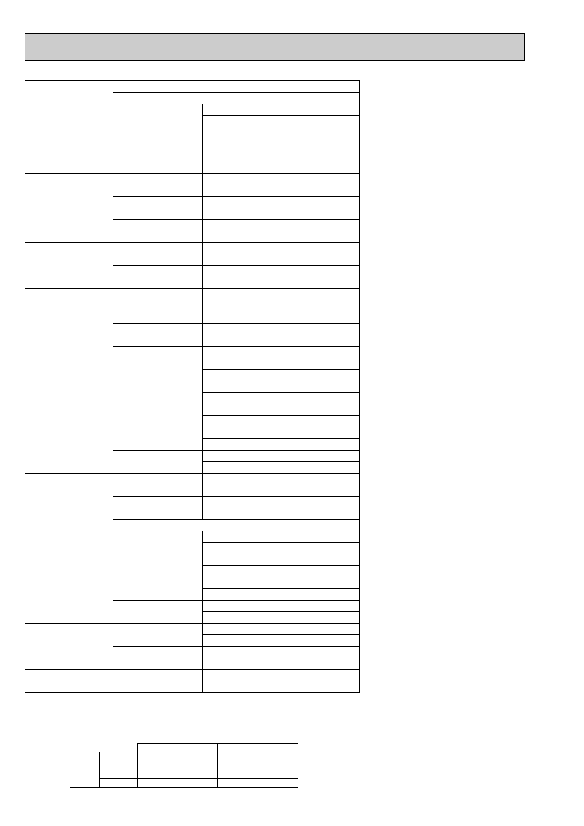
Model name Indoor unit PSA-RP71GA
Outdoor unit PUHZ-RP71VHA
Cooling Capacity Btu/h 24,200
kW 7.1(3.3-8.1)
Total input kW 2.20
EER 3.23
Energy label class A
SHF 0.73
Heating Capacity Btu/h 27,300
kW 8.0(3.5-10.2)
Total input kW 2.49
COP 3.21
Energy label class C
Booster heater kW -
Power supply Phase [ 1
Cycle Hz 50
Voltage V 230
Breaker size A 25
Indoor unit Air flow CMM 15-18
(Low-High) CFM 530-635
External pressure Pa 0
Sound level dB(A) 40-45
(Low-High)
External finish White Munsell 0.70Y 8.59/0.97
Dimension W : mm 600
D : mm 270
H : mm 1900
W : inch 23-5/8
D : inch 10-5/8
H : inch 74-13/16
Weight kg 43
lbs 98
Unit drain pipeO.D. mm 20
inch 13/16
Outdoor unit Air flow CMM 55
CFM 1,940
Sound level at cooling dB(A) 47
Sound level at heating dB(A) 48
External finish Ivory Munsell 3Y 7.8/1.1
Dimension W : mm 950
D : mm 330+30
H : mm 943
W : inch 37-3/8
D : inch 13 + 1-3/16
H : inch 37-1/8
Weight kg 75
lbs 165
Refrigerant pipe size Gas side O.D. mm 15.88
inch 5/8
Liquid side O.D. mm 9.52
inch 3/8
Refrigerant pipe length Height difference m Max. 30
Length m Max. 50
NOTE: 1. Rating conditions (ISO T1)
Cooling Indoor : D.B. 27: (80˚F) W.B. 19: (66˚F) Outdoor : D.B. 35: (95˚F) W.B. 24: (75˚F)
Heating Indoor: D.B. 20: (68˚F) Outdoor : D.B. 7: (45˚F) W.B. 6: (43˚F)
Refrigerant piping length (one way) : 5m (16ft.)
2. Guaranteed operating range
Cooling
Heating
Upper limit
Lower limit
Upper limit
Lower limit
D.B. 35˚C, W.B. 22.5˚C
D.B. 19˚C, W.B. 15˚C D.B. -5˚C w
D.B. 28˚C
D.B. 17˚C
Indoor Outdoor
D.B. 46˚C
D.B. 21˚C, W.B. 15˚C
D.B. -11˚C, W.B. -12˚C
3. Guaranteed voltage
198~264V, 50Hz
4. Above data based on indicated voltage
Indoor unit Single phase 230V 50Hz
Outdoor unit
w If optional Air protect guide installed. D.B.-15:
Single phase 230V 50Hz
23
Page 24
Model name Indoor unit PSA-RP100GA PSA-RP125GA PSA-RP140GA
Outdoor unit PUHZ-RP100VHA PUHZ-RP125VHA PUHZ-RP140VHA
Cooling Capacity Btu/h 34,100 42,700 47,800
kW 10.0(4.9-11.4) 12.5(5.5-14.0) 14.0(5.5-15.3)
Total input kW 2.99 4.15 4.98
EER 3.34 3.01 2.81
Energy label class A B C
SHF 0.81 0.75 0.73
Heating Capacity Btu/h 38,200 47,800 54,600
kW 11.2(4.5-14.0) 14.0(5.0-16.0) 16.0(5.0-18.0)
Total input kW 3.28 4.36 4.98
COP 3.41 3.21 3.21
Energy label class B C C
Booster heater kW - - -
Power supply Phase [ 1
Cycle Hz 50
Voltage V 230
Breaker size A 32 40
Indoor unit Air flow CMM 24-31 26-33 27-35
(Low-High) CFM 850-1060 920-1165 955-1240
External pressure Pa 0
Sound level dB(A) 44-49 46-51 47-52
(Low-High)
External finish White Munsell 0.70Y 8.59/0.97
Dimension W : mm 600
D : mm 350
H : mm 1900
W : inch 23-5/8
D : inch 13-3/4
H : inch 74-13/16
Weight kg 51 53
lbs 112 117
Unit drain pipeO.D. mm 20
inch 13/16
Outdoor unit Air flow CMM 100
CFM 3,530
Sound level at cooling dB(A) 49 50
Sound level at heating dB(A) 51 52
External finish Ivory Munsell 3Y 7.8/1.1
Dimension W : mm 950
D : mm 330+30
H : mm 1350
W : inch 37-3/8
D : inch 13 + 1-3/16
H : inch 53-1/8
Weight kg 121
lbs 267
Refrigerant pipe size Gas side O.D. mm 15.88
inch 5/8
Liquid side O.D. mm 9.52
inch 3/8
Refrigerant pipe length Height difference m Max. 30
Length m Max. 75
NOTE: 1. Rating conditions (ISO T1)
Cooling Indoor : D.B. 27: (80˚F) W.B. 19: (66˚F) Outdoor : D.B. 35: (95˚F) W.B. 24: (75˚F)
Heating Indoor: D.B. 20: (68˚F) Outdoor : D.B. 7: (45˚F) W.B. 6: (43˚F)
Refrigerant piping length (one way) : 5m (16ft.)
2. Guaranteed operating range
Cooling
Heating
Upper limit
Lower limit
Upper limit
Lower limit
D.B. 35˚C, W.B. 22.5˚C
D.B. 19˚C, W.B. 15˚C D.B. -5: w
D.B. 28˚C
D.B. 17˚C
Indoor Outdoor
D.B. 46:
D.B. 21:, W.B. 15:
D.B. -20:, W.B. -20:
3. Guaranteed voltage
198~264V, 50Hz
4. Above data based on indicated voltage
Indoor unit Single phase 230V 50Hz
Outdoor unit
w If optional Air protect guide installed. D.B.-15:
Single phase 230V 50Hz
24
Page 25
Model name Indoor unit PSA-RP100GA PSA-RP125GA PSA-RP140GA
Outdoor unit PUHZ-RP100YHA PUHZ-RP125YHA PUHZ-RP140YHA
Cooling Capacity Btu/h 34,100 42,700 47,800
kW 10.0(4.9-11.4) 12.5(5.5-14.0) 14.0(5.5-15.3)
Total input kW 2.99 4.15 4.98
EER 3.34 3.01 2.81
Energy label class A B C
SHF 0.81 0.75 0.73
Heating Capacity Btu/h 38,200 47,800 54,600
kW 11.2(4.5-14.0) 14.0(5.0-16.0) 16.0(5.0-18.0)
Total input kW 3.28 4.36 4.98
COP 3.41 3.21 3.21
Energy label class B C C
Booster heater kW - - -
Power supply Phase [ 3
Cycle Hz 50
Voltage V 400
Breaker size A 16
Indoor unit Air flow CMM 24-31 26-33 27-35
(Low-High) CFM 850-1060 920-1165 955-1240
External pressure Pa 0
Sound level dB(A) 44-49 46-51 47-52
(Low-High)
External finish White Munsell 0.70Y 8.59/0.97
Dimension W : mm 600
D : mm 350
H : mm 1900
W : inch 23-5/8
D : inch 13-3/4
H : inch 74-13/16
Weight kg 51 51 53
lbs 112 112 117
Unit drain pipe O.D. mm 20
inch 13/16
Outdoor unit Air flow CMM 100
CFM 3,530
Sound level at cooling dB(A) 49 50
Sound level at heating dB(A) 51 52
External finish Ivory Munsell 3Y 7.8/1.1
Dimension W : mm 950
D : mm 330+30
H : mm 1350
W : inch 37-3/8
D : inch 13 + 1-3/16
H : inch 53-1/8
Weight kg 135
lbs 298
Refrigerant pipe size Gas side O.D. mm 15.88
inch 5/8
Liquid side O.D. mm 9.52
inch 3/8
Refrigerant pipe length Height difference m Max. 30
Length m Max. 75
NOTE: 1. Rating conditions (ISO T1)
Cooling Indoor : D.B. 27: (80˚F) W.B. 19: (66˚F) Outdoor : D.B. 35: (95˚F) W.B. 24: (75˚F)
Heating Indoor: D.B. 20: (68˚F) Outdoor : D.B. 7: (45˚F) W.B. 6: (43˚F)
Refrigerant piping length (one way) : 5m (16ft.)
2. Guaranteed operating range
Cooling
Heating
Upper limit
Lower limit
Upper limit
Lower limit
D.B. 35˚C, W.B. 22.5˚C
D.B. 19˚C, W.B. 15˚C D.B. -5: w
D.B. 28˚C
D.B. 17˚C
Indoor Outdoor
D.B. 46:
D.B. 21:, W.B. 15:
D.B. -20:, W.B. -20:
3. Guaranteed voltage
198~264V, 50Hz
4. Above data based on indicated voltage
Indoor unit Single phase 230V 50Hz
Outdoor unit
w If optional Air protect guide installed. D.B.-15:
Single phase 230V 50Hz
25
Page 26
3
PLA-RP60,71AA
PLA-RP35,50AA
Models
PLA-RP100,125,140AA
241
281
A
258
298
B
80
84
C
Receiver
Operation lamp
DEFROST/STAND BY lamp
Emergency operation switch (cooling)
A
(WIRELESS PANEL)
Emergency operation switch (heating)
Branch duct hole
(Cut out hole)
{175
{150
14 - {2.8
Burring hole
350
90
70
_
100 100 90
100
130
155
167
Suspension bolt pitch
Ceiling hole
Branch
duct hole
Suspension bolt pitch
Ceiling hole
840
197 159
159
605
159192
98
89
C
840
860 - 91020 - 45 20 - 45
20 - 4520 - 45
Fresh air intake
Branch duct hole
860 - 910
810
159
16
Terminal block
Drain pipe
VP-25connection
(O.D.{32)
Ceiling surface
Power line entry
Suspension bolt lower edge
Suspension bolt M10
or W3/8
Control wire entry
Feeding hole
(Drain pump)
37428660
17
+5
0
30
190
170
140
50 - 70
105
A
B
1
2
High efficiency filter
& Fresh air intake casement (option)
17
+5
0
135
Air outlet hole
Vane motor
Auto vane
Drain hole
Grille
Air outlet hole
Air intake hole
411
Air intake hole
Air intake grille
577
77 51
M
M
M
A
M
950
51 77
950
577
411
RP35, 50
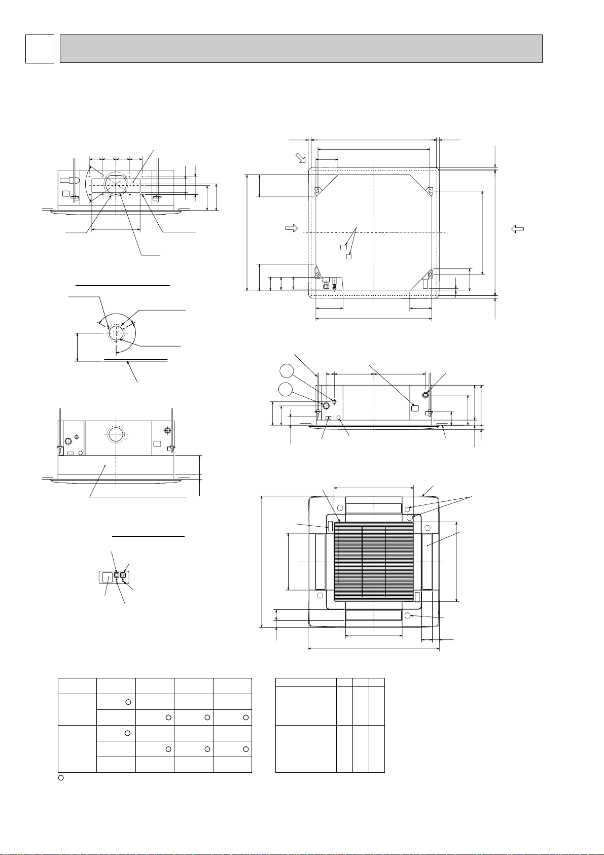
Use the current nuts meeting the pipe size of the outdoor unit.
Available pipe size
Factory flare nut attachment to the heat-exchanger.
1 LIQUID SIDE
2 GAS SIDE
RP60 RP71
[6.35 [6.35 — —
[9.52 [9.52 [9.52 [9.52
[12.7 — — —
[15.88 [15.88 [15.88 [15.88
———[19.05
RP100, 125, 140
Detail drawing of fresh air intake
3 - {2.8
Burring hole
{125
Burring hole pitch
{100
(Cut out hole)
Ceiling surface
120
_
120_
158
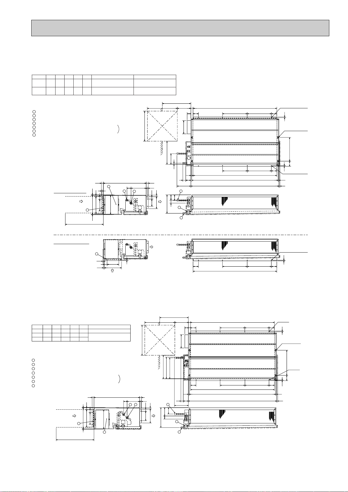
OUTLINES AND DIMENSIONS
INDOOR UNIT
PLA-RP35AA PLA-RP50AA PLA-RP60AA PLA-RP71AA
PLA-RP100AA PLA-RP125AA PLA-RP140AA
Unit : mm
26
Page 27
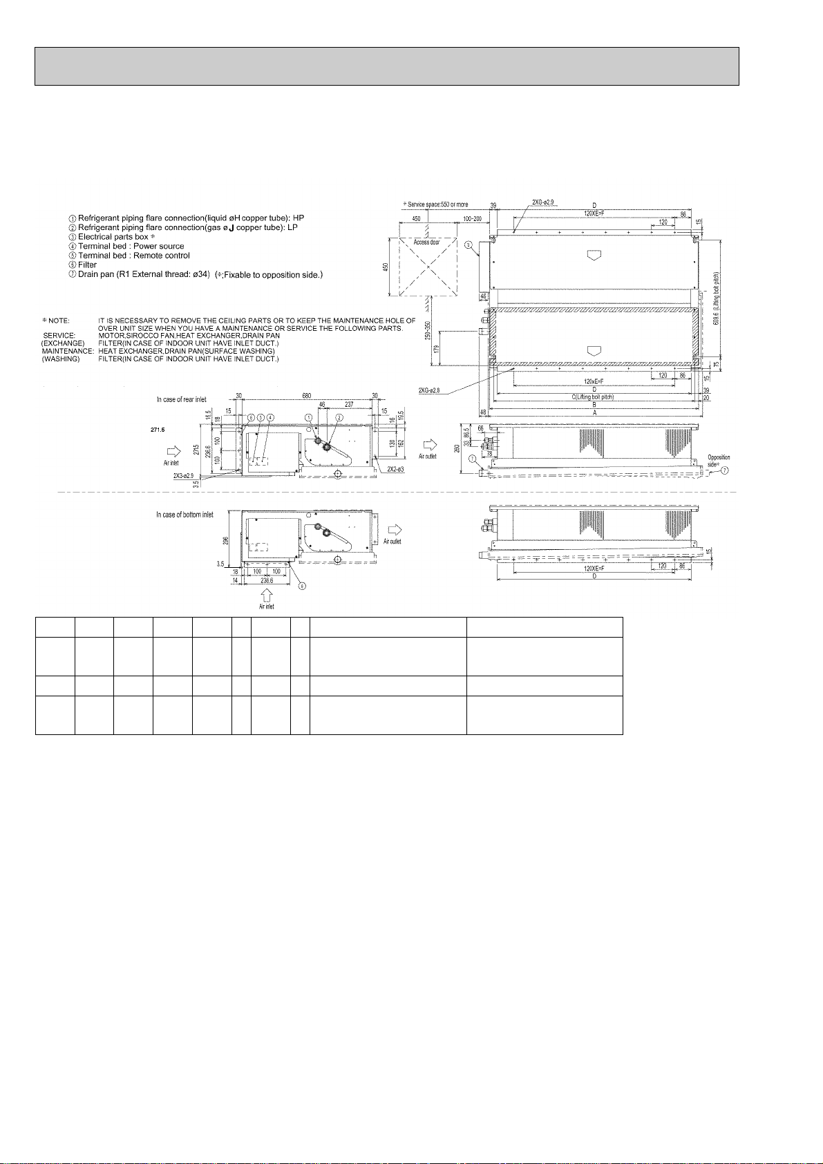
PEAD-RP35EA
2
1
3
4
5
6
7
Refrigerant piping flare connection (liquid [ F copper tube):HP
Refrigerant piping flare connection (gas [G copper tube):LP
Drain R1(External thread)
Electrical parts box
Drain Pump (Option)
Drain Pipe (Option) ... Flexible joint VP-25(I.D.
[
32)
Filter
R407C Outdoor unit : 9.52
F
R410A Outdoor unit : 6.35 w
R407C Outdoor unit : 9.52 w
Outdoor unit (SUZ) : 6.35
EDCBA
804830
-
305772
Model
RP60
R407C Outdoor unit : 15.88
G
R410A Outdoor unit : 12.7 w
15.88
104410702902801012
RP35,50
w Setting at shipment
2
1
3
4
Air inlet
Air outlet
Access door
55
50~150
81
197
Service space:500 or more
Keep duct-work length 850mm or more.
Be sure to apply the air filter
near the air inlet grille.
5
6
75
44
18
365~465
B 81
10
56 355
7
159
243
Air outlet
Air inlet
7
Lifting bolt hole
(14×22)
10- [3 (RP35,50)
12-
[
3 (RP60)
In case of rear inlet
In case of bottom inlet
10- [3 (RP35,50)
12-
[
3 (RP60)
D
30
C
10
81BC
A
450
450
10- [3 (RP35,50)
12-
[
3 (RP60)
176
40
288
256
3.5
3.5
10
109
179
10
35
24
30640
30
21
277
80
45
282
13
13E
A
61 227
29
85
40
176
10
15
3.5
256
BC 81
10
81
A
Set
R407C outdoor unit : 19.05158416104704601552RP140
15.8810441070290
F
R410A Outdoor unit : 15.88 w
EDCBA
12841310370360
2801012
1252
Model
RP100,125
RP71
w
Setting at shipment
7
44
243
308
323
75
6
5
13
Refrigerant piping flare connection (liquid [9.52 copper tube):HP
Refrigerant piping flare connection (gas [F copper tube):LP
Drain R1 (External thread)
Electrical parts box
Drain Pump (Option)
Drain Pipe (Option) ... Flexible joint VP25(I.D.[32)
Filter
Service space:500 or more
81
365~465
197
81
50~150
55
29
Access door
Air outlet
Air inlet
4
3
1
2
7
6
5
4
3
2
1
113
307
122
12-[3
(14x22)
Lifting bolt hole
45
Set
210
12-[3
450
450
140
282
680
3.5
3.5
30
319
261
181
40
30
A
C B
81
10
375
10
80
C B 81
A
E 13
30D
20
35
30
1053 169
Keep duct-work length 850mm or more.
Be sure to apply the air filter
near the air inlet grille.
PEAD-RP50EA
PEAD-RP60EA
Unit : mm
PEAD-RP71EA
PEAD-RP100EA
PEAD-RP125EA
PEAD-RP140EA
27
Page 28
PEAD-RP60GA
Model
ABCDE
7
7
9
8
9.52
9.52
15.88
15.88
8
10
FG H J
RP60
RP71
RP100
1125
1125
1365
1090
1090
1330
1050
1050
1290
1012
1012
1252
840
840
1080
Outdoor unit(SUZ) : 6.35
Other outdoor unit : 9.52 w
R410A Outdoor unit : 15.88 w
R407C Outdoor unit : 19.05
w Setting at shipment
PEAD-RP71GA
PEAD-RP100GA
Unit : mm
28
Page 29
50
55
530
690
(130)
22.5
4070
105 510 35
40 40
650
15
15
730
155 155155
14 220 120
3.2
300242
2656075
35
45
20 345
11
11
672
22.5
20 20690
15
2512512525
100
600
70
(530)
300
900
(10)
25
562
21
(10)381
858525
15
70
11
14514524.5
33920
418
90
200 200
250 175
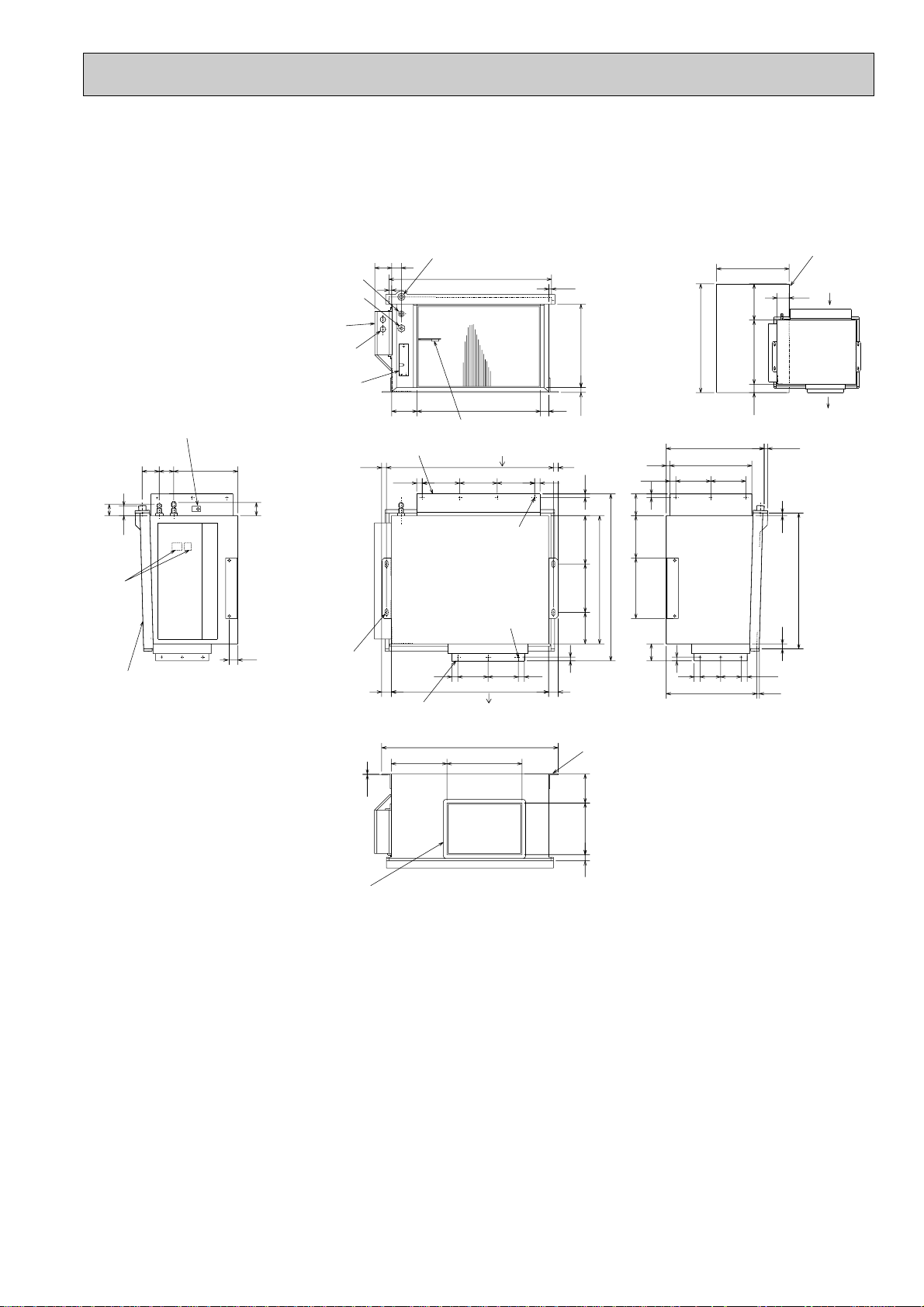
Terminal
block
4-12 ✕ 30
oblong
Suspension
bolt holes
Air intake
Air outlet
Service space
(opening)
in the ceiling
Heat insulator t10
(Drainage pan)
Room temperature thermistor
Drainage pan connection R1
Wiring entry(2-[22holes)
Refrigerant-pipe flared
connection [15.88(5/8)
Refrigerant-pipe flared
connection [9.52(3/8)
Electrical parts box
Service panel
(Condenser/evaporator
temperature thermistor)
Service panel
(Room temperature thermistor)
Air intake
Air intake duct flange
14-[2.9 holes
For air intake
duct connection
Heat insulator t10
Air outlet duct flange
Air outlet
(Drainage pan)
12-[2.9 holes
For air outlet
duct connection
Mounting plate
PEA-RP71EA
Unit : mm
29
Page 30
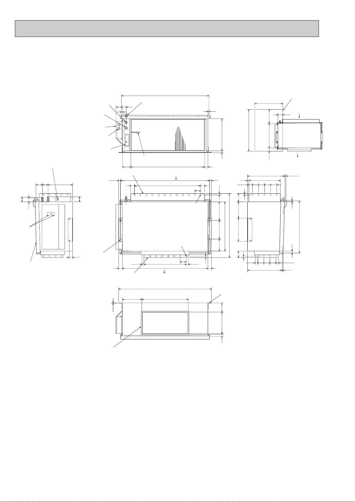
PEA-RP100EA
50
60
690
530
27.5
15
3.2
14 250 98
1000
500
20 345
11
65
656527.5
(130)
65
15
65656539.5
(10)
562
21
(10)381
15
70
11
33920
418
90
200 200
250 175
24570
45
15
217
35
79590
942
11
4070
960
65
65✕11=715
40
40
2020
65
65✕7=455 22.522.5
920
4040
70
900
300
(530)
70
600
100
Terminal
block
34-[2.9 holes
For air outlet
duct connection
(Drainage pan)
Air outlet
Air intake
(Drainage pan)
Drainage pan connection R1
Refrigerant-pipe flared
connection [9.52(3/8)
Refrigerant-pipe flared
connection [15.88(5/8)
Electrical parts box
Wiring entry(2-[22holes)
Room temperature thermistor
Air intake
Air intake duct flange
Air outlet
24-[2.9 holes
For air outlet
duct connection
Air outlet duct flange
Heat insulator t10
Heat insulator t10
Service space
(opening)
in the ceiling
Service panel
(Room temperature thermistor)
Service panel
(Condenser/evaporator
temperature thermistor)
4-12 ✕ 30
oblong
Suspension
bolt holes
35
Mounting plate
Unit : mm
30
Page 31

PEA-RP125EA
50
60
690
530
3.2
11 11
1142
20 345
900
14 250 84
(130)
15
27.5 27.5
27.5
15
39.524570
45
381
15
70
33920
90
200 200
250 175
65✕13=845
65✕14=910
65
65
1160
42.5
2020
70 40
117
15
1200
405
70
112040 40
35
995
90
42.5
300
(530)
70
100
600
900
11
(10)
21
562
(10)
65 65 65
65 65 65 27.5
65
Refrigerant-pipe flared
connection [15.88(5/8)
Refrigerant-pipe flared
connection [9.52(3/8)
4-12✕30
oblong
Suspension
bolt holes
Terminal
block
Air outlet
Air intake
Service space(opening)
in the ceiling
Air intake duct flange
(Drainage pan)
(Drainage pan)
40-[2.9 holes
For air outlet
duct connection
36-[2.9 holes
For air outlet
duct connection
Drainage pan connection R1
Electrical parts box
Wiring entry(2-[22holes)
Room temperature thermistor
Air intake
Heat insulator t10
Air outlet duct flange
Air outlet
Heat insulator t10
Service panel
(Condenser/evaporator
temperature thermistor)
Service panel
(Room temperature
thermistor)
35
Mounting plate
Unit : mm
31
Page 32

PEA-RP140EA
60
4040
37.5
381 (10)
(10)405
6565
39.5
339
65 65
25 100100
24570
50
45
70
160 1000
1385
9814 250
3.2
11
562
690
1415
11
1327
100
153
15
70
15
90175250
1305
45
130✕7=91045
15
530
(130)
200 200
70
15
40
65✕16=104037.5
20
(20)
1345
20 345
90
1115
900
600
100
70
(530)
300
Refrigerant-pipe flared
connection [15.88(5/8)
4-12✕30
oblong
Suspension
bolt holes
Terminal
block
Refrigerant-pipe flared connection
[9.52(3/8)
Air intake
Service space(opening)
in the ceiling
Air outlet
130
65
(Drainage pan)
Air outlet duct flange
22-[3.1 holes
For air outlet
duct connection
Air outlet
44-[2.9 holes
For air outlet
duct connection
Air intake duct flange
Air intake
Drainage pan connection R1
(Drainage pan)
Room temperature thermistor
Service panel
(Condenser/evaporator
temperature thermistor)
Wiring entry(2-[22holes)
Electrical parts box
Heat insulator t10
Heat insulator t10
Service panel
(Room
temperature
thermistor)
35
Mounting plate
Unit : mm
32
Page 33

PEH-RP200MYA
Unit : mm
(B)
730
200
530
(A)
199
200
13132
400
20
(B)
1240
1280
1880
(C)
(D)
20
200
(1)
25 75
428500
928
(2)
(3)
(A)
(1) When connecting air inlet
(2) When installing the suspension fixtures prior to installation of the indoor unit without inlet duct
(3) When hanging the indoor unit directly without inlet duct
(A) Service space
(B) Suspension bolt pitch
(C) Air inlet
(D) Air outlet
REFRIGERANT PIPE [25.4
(1 BRAZE)
20
42
156
344
152
AIR INLET
ACCESSORY PIPE
[
9.52(3/8 BRAZE)
(USE FOR ONLY R410A)
130
95
42
AIR INLET SENSOR
15
130
210 116
33
DRAIN: Rc 1
REFRIGERANT PIPE
(1/2 BRAZE)
104
31
40
100
1102
34
130130130130130130130130
31
24- [3.1 HOLES
AIR INLET DUCT
FLANGE
CONTROL BOX
20
4235
1280
22- [3.1 HOLES
AIR OUTLET DUCT
650
562
7053050
[
12.7
15
100 25
25 100
CONTROLLER
382
AIR OUTLET
WIRING HOLE [27
(AIR INLET SIDE)
CONNECT WIRE (PEH-PUH)
WIRING HOLE [27
(AIR INLET SIDE)
FLANGE
428
POWER SUPPLY
WIRING HOLE [27
(AIR INLET SIDE)
40
46
55 55 156
120
DUCT EARTH POINT
(BOTH DUCT SIDE)
1380
1320
1240
1000
1264
20
15
4513013013013013013013045
120
131 200 199
4- [12 HOLES
(FOR HUNGING
<FIELD SUPPLY>
40
98250
14
BOLT M10)
Note: When connecting duct to the inlet side, remove the air filter attached to the unit body, and mount
an air filter onto the inlet duct side separately.
33
Page 34

PEH-RP250MYA
POWER SUPPLY
WIRING HOLE [27
(AIR INLET SIDE)
CONTROLLER
WIRING HOLE [27
(AIR INLET SIDE)
CONNECT WIRE
(PEH-PUH)
WIRING HOLE [27
(AIR INLET SIDE)
DUCT EARTH POINT
(BOTH DUCT SIDE)
428
1440 40
220
40
1520
1000
220
1464
98
250
14
46
55 55 156
1580
AIR INLET DUCT
FLANGE
26-[3.1 HOLES
34
66
1302
104
130130130130130130130130
66
CONTROL BOX
4-[12 HOLES
22-
[
3.1 HOLES
AIR OUTLET DUCT
FLANGE
20
20
1480
15
45130130130130
130
130
45
(FOR HUNGING
BOLT M10)
<FIELD SUPPLY>
100
40
423
5
131 200 199
130
130
(1) When connecting air inlet
(2) When installing the suspension fixtures prior to installation of the indoor unit without inlet duct
(3) When hanging the indoor unit directly without inlet duct
(A) Service space
(B) Suspension bolt pitch
(C) Air inlet
(D) Air outlet
1440
20
530
13132
200
199
400
730
200
1480
2080
200
20
(A)
(C)
(B)
(B)
(D)
AIR INLET SENSOR
REFRIGERANT PIPE [12.7
(1/2 BRAZE)
REFRIGERANT PIPE
[
28.6 (1-1/8 BRAZE)
AIR INLET
AIR OUTLET
152
650
95
156
344
20
15
7053050
130
130
42
42
DRAIN: Rc 1
33
562
382
25 100
100 25
15
210 116
928
428500
25 75
(1)
(2)
(3)
(A)
Note: When connecting duct to the inlet side, remove the air filter attached to the unit body, and mount
an air filter onto the inlet duct side separately.
Unit : mm
34
Page 35

INDOOR UNIT
BYOFF
ON STAND
HEATCOOL
OFF BY
ON STAND
COOL HEAT
ÅrÇoÇoÅqÅ@ëOñ Å@ÇeÇqÇnÇmÇs ÅrÇoÇoÅqÅ@ëOñÅ@ÇeÇqÇnÇmÇs
r.SLI.SLI
m m
MITSUBISHI ELECTRICMITSUBISHI ELECTRIC
r.S.S
L
I
m m
MITSUBISHI ELECTRICMITSUBISHI ELECTRIC
Knock out hole for right piping
Refrigerant pipe.Drain pipe.
Wiring hole
21
Right side
Less than 15
70
245
60
235
Auto vane
Front view
Air intake
Air intake
Air intake
Air intake
198
53
340
715 225
340 80 280 233
990
21
Left side
Knock out hole for left piping
Refrigerant pipe.Drain pipe.Wiring hole.
60
70
245
(Necessary clearance for
Unit installation)
Right side
Allowing clearances
Front view
Less than 130
50 or more 150 or more
180 or more 30 or more
for bolts
Left-rear
piping hole
left-rear piping
R52.5
R52.5
Installation plate
balance point hole
Details of installation plate
49-[5hole
for tapping screw
Knock out hole for
right-rear piping
Right-rear
piping hole
Unit center
14-[14hole
Knock out hole for
425
420
170
190
210
230
0
322
0355580130
190
230
272
310
0
35
95
150
205
260
320
345
495
20
75
135
190
245
300
360
405
495
32
0
w1 Sleeves are available on the market.
w2 This size shows the lower end of through hole.
[90~[100[90
Through hole
Sleeve w1
35, 50
Model
R
52.5
R52.5
Gas pipe
Liquid pipe
Terminal block for
Terminal block to
outdoor unit
Filter grip
Service panel
(Power supply access)
(Flexible hose total length800)
(Right side piping
installation)
(Left side piping
installation)
Unit drain pipe O.D.20
Front view(to open the grille)
700
449
86
581 54
31 280
35
Knock out hole for under piping
Refrigerant piping.Drain pipe.
Wiring hole
12-Louvers(manual)
Air outlet
Lower side
80
50
395400
190
60
70 35
79
160 40
235
705
power supply (Heater (PKH-P35, 50GALH only))
153
GAS SIDE
LIQUID SIDE
RP35, 50
P35, 50
[6.35
[9.52
[12.7
[15.88
—
[9.52—[15.88
Use the current nuts meeting the pipe size of the outdoor unit.
Available pipe size
: Factory flare nut attachment to the heat - exchanger.
PKA-RP35GAL PKA-RP50GAL
Unit : mm
35
Page 36

PKA-RP60FAL
235
45
235
45
235
45
235
62.5
13
58
42
340
197
Top
Front
Right side
Left side
1400
1090
Air intake
235
C
Knock out hole for right piping
Refrigerant pipe. Drain pipe
Knock out hole for
left piping
Drain hose for
left-hand side piping
Drain hose
Lower side
Auto vanes
(Gas pipe)
Drain hose O.D.20
Bolt
Gas pipe
15
(Liquid pipe)
Liquid pipe [9.52(3/8F)
Gas pipe [15.88(5/8F)
Liquid pipe
A
30
32
39
98
37
74
439
100
30
37
74
4
2980
280
3030
18430
60
10
39
37
65
100
AB C
Knock out hole for wiring
25
1110
183
240
B
1120
552
55
120
107
111
Air outlet
552
Air outlet
Louvers (manual)
Under panel
Removable at left-hand
side piping
Knock out hole for under-piping
Refrigerant pipe. Drain pipe
Rear piping opening
Range for left rear piping opening
12-ø6 hole for
tapping screw
66-ø6 hole for
tapping screw
Wall fixture
Unit center
32-ø12 hole for bolt
225
18
18
91
900
990
455
285
245
19
240 280 314
610
90
Drainage range
on left-hand side
Drainage range
on right-hand side
10 91=(910)
180
Terminal block for heater (PKH only)
Terminal block for indoor/outdoor connecting line
Display section
Receiving
section
Power lamp
Emergency switch(Heat)
Emergency switch(Cool)
Defrosting Initial heating lamp
PKA-RP71FAL
Unit : mm
36
Page 37

PKA-RP100FAL
235
45
235
45
235
45
235
45
235
62.5
13
58
42
340
197
Top
Front
Right side
Display section
Receiving
section
Power lamp
Emergency switch(Heat)
Emergency switch(Cool)
Defrosting Initial heating lamp
Left side
1680
1370
Air intake
235
C
Knock out hole for right piping
Knock out hole for left piping
Drain hose for left-hand side piping
Drain hose
Drain hose
Lower side
Auto vane
(Gas pipe)
Bolt
Gas pipe
15
(Liquid pipe)
Liquid pipe
A
30
32
39
98
37
74
439
100
30
37
74
4
2980
280
3030
18430
60
10
39
37
65
100
AB C
Knock out hole for wiring
25
1110
183
240
B
1400
55
120
102
111
694
Air outlet
694
Air outlet
Louvers (manual)
Under panel
(Removable at left-hand side piping)
Knock out hole for under-piping
Refrigerant pipe. Drain pipe
Rear piping opening
Range for left rear piping openingRange for left rear piping opening
12-ø6 hole for tapping screw
84-ø6 hole for
tapping screw
Wall fixture
Unit out line
Unit center
41-ø12 hole for bolt
295 225
18
18
91
900
1270
595
285
245
19
240 280 314
750
90
Drainage range
on right-hand side
13 91=(1183)
180
Drainage range
on left-hand side
Terminal block for heater (PKH only)
Terminal block for indoor/outdoor connecting line
Drain hose O.D.20
: Factory flare nut attachment to the
heat-exchanger.
GAS SIDE
LIQUID SIDE
RP100
[9.52
[15.88
[19.05
P100
[9.52
[19.05
Use the current nuts meeting the pipe size
of the outdoor unit.
Available pipe size
Unit : mm
37
Page 38

INDOOR UNIT
180
210
157
15
85
182 liquid
201 gas
241 (Drainage)
Air intake
918
161 90
254
680
506 56
Electrical box
226
70
6
2
7
17
150
140
70
320
80
933 (suspension bolt pitch)
983
1000
Air outlet
81
904
76
525
928
352
263
171
138
86
46 175 1
131
38
38
79
161
32
179
42
6~7
Ceiling
Electrical box
[Front view]
When electrical
box is pulled
down
3
2
8
5
1
4
[15.88
[9.52
P50
[15.88
[12.7
[6.35
Available pipe size
[9.52
4 GAS SIDE
5 LIQUID SIDE
RP50
Use the current nuts meeting the pipe size of the outdoor unit.
: Factory flare nut attachment to the heat-exchanger.
PCA-RP50GA
NOTES:
1. Use M10 or W3/8 screws for anchor bolt.
2. When optional drain lift-up mechanism is installed, always provide
upward piping for refrigerant piping.
Unit : mm
1 Drainage pipe connection (26mm I.D.)
2 Drainage pipe connection (for the left arrangement)
3 Knock out hole for left drain-piping arrangement
4 Refrigerant-pipe connection (gas pipe side/flared connection)
5 Refrigerant-pipe connection (liquid pipe side/flared connection)
6 Knock out hole for upper drain pipe arrangement
7 Knock out hole for left drain pipe arrangement
8 Knock out hole for wiring arrangement
38
Page 39

PCA-RP60GA
161 90
254
680
506 56
1240 (suspension bolt pitch)
140
150
320 80
17
70
6
1290
1214
210
180
81 76
1310
Air outlet
1228
Air intake
85
182
201
241
15
157
(liquid)
(5/8F gas)
(Drainage)
7
2
Electrical box
70
226
3
2
8
5
1
4
Electrical box
When electrical
box is pulled
down
[ Front view ]
Ceiling
32
179
161
38
3879
42
6~7
525
1235
416
263
171
138
86
131
175 1
46
: Factory flare nut attachment to the heat-exchanger.
4 GAS SIDE
5 LIQUID SIDE
Use the current nuts meeting the pipe size of the outdoor unit.
Available pipe size
RP71,P60,P71
RP60
[6.35
[9.52
[15.88
[9.52
[15.88
PCA-RP71GA
NOTES:
1. Use M10 or W3/8 screws for anchor bolt.
2. When optional drain lift-up mechanism is installed, always provide
upward piping for refrigerant piping.
Unit : mm
1 Drainage pipe connection (26mm I.D.)
2 Drainage pipe connection (for the left arrangement)
3 Knock out hole for left drain-piping arrangement
4 Refrigerant-pipe connection (gas pipe side/flared connection)
5 Refrigerant-pipe connection (liquid pipe side/flared connection)
6 Knock out hole for upper drain pipe arrangement
7 Knock out hole for left drain pipe arrangement
8 Knock out hole for wiring arrangement
39
Page 40

PCA-RP100GA
161 90
254
680
506 56
1228
Air intake
1214
270
207
81 96
1310
Air outlet
1240 (suspension bolt pitch)
140
150
320 80
18
70
6
87
182
198
245
16
217
(3/8F liquid)
(5/8F, 3/4F gas)
(Drainage)
7
2
Electrical box
70
229
3
2
8
5
1
4
Electrical box
When electrical
box is pulled
down
[ Front view ]
Ceiling
93
160
38
38 140
42 239
6~7
525
1235
687
263
171
138
86
192
236
1
45
Use the current nuts meeting the pipe size of the outdoor unit.
:Factory flare nut attachment to the heat-exchanger.
4 GAS SIDE
5
LIQUID SIDE
Available pipe size
RP100
[9.52
[15.88
[19.05
P100
[9.52
[19.05
Unit : mm
NOTES:
1. Use M10 or W3/8 screws for anchor bolt.
2. When optional drain lift-up mechanism is installed, always provide
upward piping for refrigerant piping.
1 Drainage pipe connection (26mm I.D.)
2 Drainage pipe connection (for the left arrangement)
3 Knock out hole for left drain-piping arrangement
4 Refrigerant-pipe connection (gas pipe side/flared connection)
5 Refrigerant-pipe connection (liquid pipe side/flared connection)
6 Knock out hole for upper drain pipe arrangement
7 Knock out hole for left drain pipe arrangement
8 Knock out hole for wiring arrangement
40
Page 41

PCA-RP125GA
161 90
254
680
506 56
1535
Air intake
1524
270
207
81 96
1620
Air outlet
1547(suspension bolt pitch)
140
150
320 80
18
70
6
87
182
198
245
16
217
(3/8F liquid)
(5/8F, 3/4F gas)
(Drainage)
7
2
Electrical box
70
229
3
2
8
5
1
4
Electrical box
When electrical
box is pulled
down
[ Front view ]
Ceiling
93
160
38
38 140
42 239
6~7
525
1545
687
263
171
138
86
192
236
1
45
:Factory flare nut attachment to the heat-exchanger.
RP125,140
[19.05
[15.88
[9.52
Use the current nuts meeting the pipe size of the outdoor unit.
4 GAS SIDE
5 LIQUID SIDE
Available pipe size
P125,140
[19.05
[9.52
PCA-RP140GA
NOTES:
1. Use M10 or W3/8 screws for anchor bolt.
2. When optional drain lift-up mechanism is installed, always provide
upward piping for refrigerant piping.
Unit : mm
1 Drainage pipe connection (26mm I.D.)
2 Drainage pipe connection (for the left arrangement)
3 Knock out hole for left drain-piping arrangement
4 Refrigerant-pipe connection (gas pipe side/flared connection)
5 Refrigerant-pipe connection (liquid pipe side/flared connection)
6 Knock out hole for upper drain pipe arrangement
7 Knock out hole for left drain pipe arrangement
8 Knock out hole for wiring arrangement
41
Page 42

PCA-RP71HA
Unit : mm
(Gap to ceiling)
90˚
130
9
[222
[200
Terminal block box
78
(122)
480
Allowing clearances
6
4
85
14018
45
1
210
2
165
120
90
366
38
318
176
105
650
Less than
Rear wall
Adjustable part
2 ~ 3
300
Ceiling
Less than
Less than
250
500
1001136
or more
or more
295
254
70~90
43
320 80
495
<Suspension bolt pitch>
243
75
Option parts:duct flange( [ 200). model: PAC-SF28OF-E(1 pcs.)
Terminal block(remote controller)
Terminal block(indoor/outdoor connecting line)
Knock out hole for upper refrigerant-pipe arrangement
Flexible hose(accessory) Drainage pipe connection(26mm I.D.)
Refrigerant-pipe connection(gas pipe side/flared connection : 5/8F)
1
Knock out hole for behind refrigerant-piping arrangement
Refrigerant-pipe connection(liquid pipe side/flared connection : 3/8F)
2
3
130 15
5
2
5
4
<gas>
<liquid>
175
110
21
Knock out hole for wiring arrangement : 2- [ 27
6
197
Knock out hole (duct for fresh air intake): 2- [ 200
8
7
9
75
Suspension bolt
280
<Air outlet>
1
3
13
70
289
650
Inspection port
75
<Air outlet>
1224
<Suspension bolt pitch>
1180
986
1136
handle
<Flexible hose(accessory)>
16
288
<Filter contour dimension>
(pipe sensor)
Filter (3-pieces)
258 110 102
or more
100
360
Filter element for the exchange
model:PAC-SG38KF-E (12pcs.)
<Air intake>
1098
<Air intake>
Terminal block box
Electrical box
42
The half bottom of FAN CASING
can be separated.
1.Use M10 or W3/8 screw for anchor bolt.
NOTES.
Page 43

PCA-RP125HA
(Gap to ceiling)
90˚
[222
[200
9
130
440440298
2~3
250
Less than
or more
500
Unit : mm
78
Terminal block box
(122)246
6
90 120
295
254
243
280
<Air outlet>
110 102
38 210
176
105
Adjustable part
3
13
70
289
650
<Flexible hose(accessory)>
Inspection port
(pipe sensor)
Filter (4-pieces)
4
2
8545
14018
165
1
70~90
43
320 801564
495
<Suspension bolt pitch>
75
Refrigerant-pipe connection(gas pipe side/flared connection : 5/8F, 3/4F)
Flexible hose(accessory) Drainage pipe connection(26mm I.D.)
Refrigerant-pipe connection(liquid pipe side/flared connection : 3/8F)
Knock out hole for behind refrigerant-piping arrangement
Knock out hole for upper refrigerant-pipe arrangement
Knock out hole for wiring arrangement : 2- [ 27
4
3156728
<gas>
197
175
<liquid>
110
21
Knock out hole (duct for fresh air intake) : 2- [ 200
Terminal block(indoor/outdoor connecting line)
Option parts:duct flange( [ 200). model: PAC-SF28OF-E(1 pcs.)
Terminal block(remote controller)
9
1
75
Suspension bolt
300
Allowing clearances
650
Rear wall
Less than
Less than
Ceiling
handle
360
16
288
<Filter contour dimension>
258
<Air intake>
Filter element for the exchange
1001520100
or more
or more
: Factry flare nut attachment to the heat-exchanger
[ 9.52
RP125
[ 15.88
model:PAC-SG38KF-E (12pcs.)
[ 19.05
130 15
5
2
Terminal block box
Electrical box
<Suspension bolt pitch>
1608
<Air outlet>
1370 75
1520
The half bottom of FAN CASING
can be separated.
43
1482
<Air intake>
2 LIQUID SIDE
Available pipe size
1.Use M10 or W3/8 screw for anchor bolt.
NOTES.
1 GAS SIDE
Use the current nuts meeting the pipe size
of the outdoor unit.
Page 44

PSA-RP71GA
300 or more
1
5 or more
2
Unit : mm
Front 1,000 or more
Knock out hole
for under-piping
Front side
218
VIEW "A"
95
100
90
175
55 143
Rear side
20
160
Knock out hole
for bottom fixing
277
100 or more 100 or more
40 66
Liquid pipe [9.52(3/8F)
95
Electrical parts box
46122
Terminal block for
indoor/outdoor
connection.
1. Service access allows for
insertion of screw driver.
2. Adjustable
186
Drain pipe
Gas pipe [15.88(5/8F)
47
767
714 123
590
480
110
105
Knock out hole for piping and wiring
(140 80 oval)
20
A
132
Knock out hole
for branch duct
240
Rear side
10
3838
15
111
Knock out hole for
under-piping(120 70 oval)
130
100
125
340
370
Front side
10
270
250
40
50260
Metal fixture
against overturning
520
260
240
2010
130130
controller
766
130 71
Terminal block for
heater power supply
(Only PSH-P•GAH)
1900
50
608
82730
216
115
Knock out hole for
wiring.[27
(Provided on both sides)
180
235
70
Knock out hole for refrigerant and drainage.
90 60 oval (Provided on both sides)
530
600
44
Page 45

PSA-RP100GA
PSA-RP125GA
PSA-RP140GA
300 or more
1
5 or more
2
Unit : mm
Front 1,000 or more
Knock out hole
for under-piping
Front side
218
VIEW "A"
95
Knock out hole for
under-piping(120 70 oval)
[ 9.52
P100,125,140—[ 19.05
[ 9.52
RP100,125,140
[ 15.88
[ 19.05
: Factry flare nut attachment to
LIQUID SIDE
120
GAS SIDE
277
Use the current nuts meeting the pipe size
of the outdoor unit.
Available pipe size
77
201
120
Rear side
20
140
Knock out hole
for bottom fixing
255
the heat-exchanger
Terminal block for
indoor/outdoor
100 or more 100 or more
40 66
Liquid pipe [9.52(3/8F)
95
Electrical parts box
46122
connection.
Terminal block for
heater power supply
(Only PSH-P•GAH)
1. Service access allows for
insertion of screw driver.
2. Adjustable
261
[19.05(3/4F)
Drain pipe
Gas pipe [15.88(5/8F)
47
767
714 123
590
480
110
105
Knock out hole for piping and wiring
(140 80 oval)
20
115
50
Knock out hole for
wiring.[27 (Provided on both sides)
A
132
Knock out hole
for branch duct
240
Rear side
10
3838
15
111
260
350
330
40
130
100
125
340
370
Front side
10
50260
Metal fixture
against overturning
520
260
240
2010
130130
controller
766
130 71
1900
608
82730
216
315
70
Knock out hole for refrigerant and drainage.
90 60 oval (Provided on both sides)
530
600
45
Page 46

Service panel
for charge plug
w 1 In the place where short cycle tends to occur, cooling and heating
capacity and power consumption might get lowered 10%. Air outlet
guide (optional PAC-SG58SG) will help them improve.
w 2 If air discharges to the wall, the surface might get stained.
Minimum installation space for outdoor unit
100 mm or more as long as
no obstacle is placed on the
rear and light-and-left sides
of the unit.
2 sides should be open in
the right, left and rear side.
w 2
w 1
100 mm or more
500 mm or more
Basically open
100 mm or more
Free space around the outdoor unit
(basic example)
350 mm or more
w 1
Air intake
Air discharge
Air intake
Connection for
gas pipe
Service port
Connection for
liquid pipe
Service panel
4-10 o 21 oval hole
(M10 foundation bolt)
[33 drain hole
[33 drain hole
43.6
152
155
400
347.5
45.4
365
330
300
40
Handle for
moving
600
10
300
150
287.5
Installation bolt pitch: 500
800
69
35
43
183
90
155
23
32.5
18
1. FOUNDATION BOLTS
2. PIPING-WIRING DIRECTION
Piping and wiring connection can
be made from the rear direction only.
3. ATTACHING THE CONDUIT
In order to attach the conduit, it is
necessary to fix the metal plate with
2 screws to the back panel. Procure
the metal plate and make screw holes
locally. It is recommended to use the
metal plate shown below. Align the
metal plate to the marks on the unit
and attach it.
<Foundation bolt height>
Please secure the unit firmly
with 4 foundation (M10) bolts.
(Bolts, washer and nut must
be purchased locally.)
18 or below
40
20
60
80
w Conduit hole
w The position and the size of
conduit hole depend on the
conduit to be used.
Holes for metal plate fixing screw
w The size of hole depends on the
screw to be used.
FOUNDATION
OUTDOOR UNIT
PUHZ-RP35VHA
PUHZ-RP50VHA
Unit : mm47Unit : mm
46
Page 47

PUHZ-RP60VHA
O
v
e
r 1
0
m
m
FRE
E
O
v
e
r 5
0
0
m
m
O
v
e
r 1
0
0
m
m
O
v
e
r 1
0
m
m
PUHZ-RP71VHA
Page 48

PUHZ-RP100VHA PUHZ-RP100YHA
Over
Over
Over
Over
Less than
Piping and wiring connections
can be made from 4 directions:
FRONT,Right,Rear and Below.
4 PIPING-WIRING DIRECTIONS
3 FOUNDATION BOLTS2 SERVICE SPACE
1 FREE SPACE (Around the unit)
Please secure the unit firmly
with 4 foundation (M10) bolts.
(Bolts and washers must be
purchased locally.)
<Foundation bolt height>
Dimensions of space needed
for service access are
shown in the below diagram.
The diagram below shows a
basic example.
Explantion of particular details are
given in the installation manuals etc.
FREE
O
v
e
r
1
0
m
m
O
v
e
r
1
0
m
m
O
v
e
r
1
5
0
m
m
O
v
e
r
1
5
0
m
m
30
FOUNDATION
10
500
500
100
Service space
PUHZ-RP125VHA PUHZ-RP125YHA
PUHZ-RP140VHA PUHZ-RP140YHA
Unit : mm
A
1,076
930
2-U Shaped notched holes
(Foundation Bolt M10)
600175 175
Rear Air Intake
Installation Feet
417
37028 19
5653
45
42
66
330
Side Air Intake
(Foundation Bolt M10)
2-12o36 Oval holes
Air Discharge
30
Terminal connection
Left • • • Power supply wiring
950
Earth terminal
322
Handle for moving
Right • • Indoor/Outdoor wiring
Service panel
A
Handle for moving
635371
1350
2
1
w1 447
w1 443
Front piping cover
Rear piping cover
71
23
Bottom piping hole
(Knock-Out)
71
81 219
RP·VHA
RP·YHA
Drain hole
(5-[33)
14514522030 145
Side Air Intake
Rear Air Intake
Handle for moving
Handle for moving
Handle for moving
Indication of STOP VALVE connection location.
Refrigerant LIQUID pipe connection (FLARE)[ 9.52 (3/8F)
Refrigerant GAS pipe connction (FLARE)[15.88 (5/8F)
• • •
• • •
Example of Notes
• • •
2
1
w1
48
Power supply wiring hole
(2-[27Knock-Out)
Rear trunking hole
(Knock-Out)
Rear piping hole
92
[92
4045
5527
637323
Right trunking hole
(Knock-Out)
(2-[27Knock-Out)
4075
Power supply wiring hole
[92
Air intake
6373
Right piping hole
(Knock-Out)
922723
637323
5527
40 45
[92
Power supply wiring hole
(2-[27Knock-Out)
Piping Knock-Out Hole Details
Front trunking hole
(Knock-Out)
Front piping hole
(Knock-Out)
65
5519
92
65
92
(Knock-Out)
Page 49

PUHZ-RP200YHA
PUHZ-RP250YHA
Unit : mm
(Rear Side)
Service panel
380
28.58
25.4
2
[
[
O.D
O.D
200
1
12.7 (1/2F)
9.52 (3/8F)
[
[
250YHA
200YHA
Refrigerant GAS PIPE connection (BRAZING)
Refrigerant LIQUID PIPE connection (FLARE)
2
1
AIR FLOW
AIR INTAKE
0
0
7
[
15
R
1798
900 750
1519
1457
MITSUBISHI
ELECTRIC
667
150
70
110
42 48
Wiring Hole([ 27 Knock-OUT)
Wiring Hole([ 40 Knock-OUT)
4350364
G
25.4
L
[
1
94
2
195821
191
0
98
60
780
736
Piping Hole([ 122 Knock-OUT)
Piping Hole([ 122 Knock-OUT)
15
R
65
375
218
Drain Hole(4-[10)
460
140
Wiring Hole([27 Knock-OUT)
Wiring Hole([40 Knock-OUT)
736
750
(780)
80
123
105
65
Front side
63
161
90
(22)
Piping Hole (Knock-OUT)
180
Drain Hole
80
317
120
70
560
900
700~796
28
12
60
FOUNDATION BOLTS PITCH & DRAIN HOLES
49
(Front Side)
Service panel
Indoor/Outdoor Wiring
Wiring Hole([ 40 Knock-OUT)
Wiring Hole([ 27 Knock-OUT)
200
Power supply Wiring (Earth wiring)
48
152
40
38
Wiring Hole([ 27 Knock-OUT)
Wiring Hole([ 40 Knock-OUT)
Page 50

WIRED REMOTE CONTROLLER
130
120
19
Unit : mm
50
Page 51

WIRELESS REMOTE CONTROLLER
159.3
55
58
19
Unit : mm
51
Page 52

4
INDOOR POWER BOARD
[LEGEND]
P.B
INDOOR CONTROLLER BOARDI.B
FUSE(T6.3AL250V)FUSE
CN2L
VARISTORZNR
CONNECTOR(LOSSNAY)
CN32
FAN CONTROL ELEMENTBCR
CONNECTOR(REMOTE SWITCH)
CN41 CONNECTOR(HA TERMINAL-A)
CN51 CONNECTOR(CENTRALLY CONTROL)
SW1
SWITCH(MODEL SELECTION) See table 1
SWITCH(
CAPACITY CORD
) See table 2
SW2
SWE
CONNECTOR(EMERGENCY OPERATION)
X1 RELAY(DRAIN PUMP)
X4 RELAY(FAN MOTOR)
LED1 POWER SUPPLY(I.B)
LED2 POWER SUPPLY(I.B)
LED3 TRANSMISSION(INDOOR-OUTDOOR)
SYMBOL NAME SYMBOL NAME SYMBOL NAME
C CAPACITOR(FAN MOTOR)
MF FAN MOTOR
MV VANE MOTOR
DP DRAIN-UP MACHINE
DS DRAIN SENSOR
H2 DEW PREVENTION HEATER
TB4
TERMINAL BLOCK (INDOOR/
OUTDOOR CONNECTING LINE)
TB2
TERMINAL BLOCK
(INDOOR UNIT POWER(OPTION))
TB5, TB6 TERMINAL BLOCK(REMOTE
CONTROLLER TRANSMISSION LINE)
TH1 ROOM TEMP.THERMISTOR
(0˚C/15kΩ,25˚C/5.4kΩ DETECT)
TH2 PIPE TEMP.THERMISTOR/LIQUID
(0˚C/15kΩ,25˚C/5.4kΩ DETECT)
TH5 COND./EVA. TEMP. THERMISTOR
(0˚C/15kΩ,25˚C/5.4kΩ DETECT)
R.B
WIRED REMOTE CONTROLLER BOARD
W.B
WIRELESS REMOTE CONTROLLER BOARD
RU RECEIVING UNIT
BZ BUZZER
LED1 LED(RUN INDICATOR)
LED2 LED(HOT ADJUST)
SW1 SWITCH(HEATING ON/OFF)
SW2 SWITCH(COOLING ON/OFF)
321
321
531
MF
FAN
(WHT)
RED
WHT
BLK
BLK
X1
X4
X1X4
C
BCR
31
DP
D.U.M
CNP
(BLU)
YLW
YLW
ORN
ORN
YLW
31 31 31 31
YLW
YLW
D.HEATER
CNC(RED)
RED
WHT
WHT
BRN
POWER
CNDK
(RED)
POWER
CND
(ORN)
21
POWER
CN2D
(WHT)
INDOOR/OUTDOOR
COMMUNICATION
CN3C
(BLU)
3131
POWER
CND
(ORN)
INDOOR/OUTDOOR
COMMUNICATION
CN3C
(BLU)
CN41CN51 CN2L
CN32
9
WIRELESS
CN90
(WHT)
BZ
5
VANE
CN6V
(GRN)
CN2S
(WHT)
CNSK
(RED)
W.B
LED2
CNB
LED1
SW1 SW2
RU
21
2
21
1
REMOCON
CN22
(BLU)
TB5
TRANSMISSION WIRES
DC12V
TB6
R.B
BLU
BLU
321 21 21
D.SENSOR
CN31
(WHT)
INTAKE
CN20
(RED)
HEATER
CN24
(YLW)
LIQUID
CN21
(WHT)
DS
TH2
21
PIPE
CN29
(BLK)
TH3
TH1
LED3 LED2 LED1
ON
OFF
SWE
Refer to tables 1
and 2.
SW2 SW1
9 5
10
76321 84
5MV5MV5
5
MV5MV
GRILLE
H2
S1
S2
TB2
TB4
POWER SUPPLY
~(1PHASE)
230V 50Hz
RED
BLU
YLW
ORN
ORN
BRN
GRN/YLW
S3
TB4
TO OUTDOOR UNIT
TO OUTDOOR UNIT
L
S1
S2
S3
N
DC
13.1V
1
2
2
3
1
P.B
ZNR
FUSE
I.B
I.B
YLW
ORN
BRN
ORN
YLW
ORN
1 (Fig.1)
NOTES:
1.Symbols used in wiring diagram above are, : Connector, : Terminal (block).
2.Indoor and outdoor connecting wires are made with polarities, make wiring
matching terminal numbers (S1,S2,S3).
3.Since the outdoor side electric wiring may change be sure to check the outdoor
unit electric wiring for servicing.
4.This dlagram shows the wiring of Indoor and Outdoor connecting wires
(specification of 230V), adopting superimposed system of power and signal.
1 ; When work to supply power separately to Indoor and Outdoor unit was applied, refer to Fig1.
2 ; For power supply system of this unit, refer to the caution label located near this diagram.
Please set the voltage using the
remote controller.
For the setting method. please refer to
the indoor unit Installation Manual.
1 2 3 4 5
ON
OFF
MODELS
Table 1
SW1
Service board
PLA-RP. AA
1 2 3 4 5
ON
OFF
MODELS
Table 2
SW2
Service board
PLA-RP35AA
PLA-RP50AA
PLA-RP60AA
PLA-RP71AA
PLA-RP100AA
PLA-RP125AA
PLA-RP140AA
1 2 3 4 5
ON
OFF
1 2 3 4 5
ON
OFF
1 2 3 4 5
ON
OFF
1 2 3 4 5
ON
OFF
MODELS
Service board
1 2 3 4 5
ON
OFF
1 2 3 4 5
ON
OFF
WIRING DIAGRAM
PLA-RP35AA PLA-RP50AA PLA-RP60AA PLA-RP71AA
PLA-RP100AA PLA-RP125AA PLA-RP140AA
52
Page 53

PEAD-RP35EA PEAD-RP50EA PEAD-RP60EA PEAD-RP71EA
PEAD-RP100EA PEAD-RP125EA PEAD-RP140EA
53
Page 54

PEAD-RP60GA PEAD-RP71GA PEAD-RP100GA
54
Page 55

PEA-RP71EA PEA-RP100EA PEA-RP125EA PEA-RP140EA
CN3C
(BLU)
INDOOR/OUTDOOR
COMMUNICATION
ORN
RED
WHT
BRN
BLU
BLK
561432
:Terminal(block).
Refer to tables
1 and 2
Please set the voltage using
the remote controller.
For the setting method,please
refer to the indoor unit
installation Manual.
Table 2
Table 1
21
BLU
BLU
TB5
w
2;For power supply system of this unit,
refer to the caution label located
near this diagram.
w1;When work to supply power separately
to Indoor and Outdoor unit was applled,
refer to Fig 1.
:Connector,
[NOTES]
1.Symbols used in wiring diagram above are,
2.Indoor and outdoor connecting wires are made with polarities,
make wiring matching terminal numbers(S1,S2,S3).
3.Since the outdoor side electric wiring may change be sure to
check the outdoor unit electric wiring for servicing.
4.This diagram shows the wiring of Indoor and Outdoor
connecting wires(speclfication of 230V), adopting
superimposed system of power and signal.
INDOOR UNIT
TB6
R.B
REMOTE CONTROLLER BOARD
TERMINAL BLOCK(REMOTE CONTROLLER
TRANSMISSON LINE)
SW1
SW2
SWITCH(MODEL SELECTION)wSee table 1
SWITCH(CAPACITY CODE)
w
See table 2
TB5
TRANSMISSION LINE)
TERMINAL BLOCK(REMOTE CONTROLLER
SYMBOL
P.B
I.B
FUSE
ZNR
CN2L
CN32
CN41
CN51
LED1
LED2
LED3
FUSE(T6.3AL250V)
VARISTOR
INDOOR CONTROLLER BOARD
INDOOR POWER BOARD
CONNECTOR(LOSSNAY)
CONNECTOR(REMOTE SWITCH))
CONNECTOR(HA TERMINAL-A)
CONNECTOR(CENTRALLY CONTROL)
POWER SUPPLY(I.B)
POWER SUPPLY(R.B)
TRANSMISSOION(INDOOR • OUTDOOR)
NAME
I.B
SWE
X4
X5
X6
SWITCH(EMERGENCY OPERATION)
RELAY(FAN MOTOR)
RELAY(FAN MOTOR)
RELAY(FAN MOTOR)
SYMBOL
NAME
SYMBOL
NAME
C
MF
TB2
TB4
TH1
TH2
TH5
CAPACITOR(FAN MOTOR)
FAN MOTOR
TERMINAL BLOCK(INDOOR UNIT POWER(OPTION))
TERMINAL BLOCK
(INDOOR/OUTDOOR CONNECTING LINE)
ROOM TEMPERATURE THERMISTOR
(0;/15K', 25;/5.4K' DETECT)
PIPE TEMPERATURE THERMISTOR/LIQUID
(0;/15K', 25;/5.4K' DETECT)
COND./EVA. TEMPERATURE THERMISTOR
(0;/15K', 25;/5.4K' DETECT)
TO
OUTDOOR
UNIT
ORN
YLW
TB4
S3
S2
S1
13
1
2
OFF
ON
SWE
I.B
1
FAN
(WHT)
X6
X6
REMOCON
CN22
(BLU)
WIRELESS
CN90
(WHT)
CN3C
(BLU)
INDOOR/OUTDOOR
COMMUNICATION
ORN
BRN
1
2
TH1
TH5
CN2L
BLU
TRANSMISSION
WIRE DC12V
TB6
1
1
2
3112
2
1
357
13
SW1SW2
1
2
2
1
R.B
P.B
CN2S
(WHT)
CNSK
(RED)
23
DC13.1V
X5 X4
X5 X4
LED3 LED2 LED1
TH2
LIQUID
CN21
(WHT)
INTAKE
CN20
(RED)
PIPE
CN29
(BLK)
CN32
CN41
CN24
POWER
CN2D
(WHT)
WHT
BLK
ORN
YLW
ZNR
FUSE
POWER
CND
(ORN)
WHT
RED
POWER
CNDK
(RED)
BLU
w1(Fig.1)
POWER
CND
(ORN)
BRN
ORN
YLW
ORN
I.B
13 13
TO
OUTDOOR
UNIT
BLU
RED
N
L
TB2
RED
BLU
POWER SUPPLY
~ (1PHASE)
230V 50Hz
S3
S2
S1
TB4
MF
C
Manufacture/Service
MODELS
Manufacture/Service
MODELS
PEA-RP140EA
PEA-RP125EA
PEA-RP100EA
PEA-RP71EA
1
1
1
1
2
2
2
2
3
3
3
3
5
5
5
5
4
4
4
4
SW2
ON
OFF
ON
OFF
ON
OFF
ON
OFF
123 54
PEA-RP.EA
SW1
ON
OFF
55
Page 56

PEH-RP200MYA PEH-RP250MYA
SUPPLY AIR
DUCT
CR
RETURN AIR
DUCT
50Hz
3N~PE
POWER SUPPLY
380/400/415V
(FIELD SUPPLY)
PEH-RP200,250MYA:15A
CIRCUIT BREAKER
Caution,
1. To protect fan motor from abnormal current,over current relays is installed.
Therefore, do not change factory set value of over current relays.
51F
INDOOR
CONTROLLER BOARD
POWER BOARD
INDOOR
TO OUTDOOR UNIT
CONNECTING WIRES
(POLAR)
REMOTE CONTROLLER
BOARD
Note:1. The dotted lines show field wiring.
2. Color of earth wire is yellow and green twisting.
3. Specification subject to change without notice.
4. Indoor and outdoor connecting wires are made with polarities,
make sure matching wiring and terminal.
5. Emergency operation
If a trouble occurs with either the remote controller or the indoor microcom puter and no other trouble exists, emergency operation for cooling or heating
can be performed by changing the setting of switch (SWE) "ON" on the
indoor controller board.
6. SW2(*1) shows PEH-RP250MYA setting.
In case of PEH-RP200MYA setting is shown as below.
7. mark is connector.
FERRITE CORE
SURGE KILLER
FB
CR
INDOOR
CONTROLLER
BOARD
SYMBOL NAME
MF1
51F
49F
TB2,4,5
TH1
TH2
FAN MOTOR (INDOOR)
OVER CURRENT RELAY (INDOOR FAN MOTOR)
INTERNAL THERMOSTAT (INDOOR FAN MOTOR)
TERMINAL BLOCK
THERMISTOR
INDOOR UNIT
REMOTE CONTROLLER
FUSE FUSE (T6.3AL250V)
ZNR VARISTOR
AUXILIARY RELAYX4-6
SW2
SWE
LED1 LED (POWER SUPPLY)
LED2
LED (POWER SUPPLY<REMOTE CONTROLLER>)
LED3
LED (TRANSMISSION<INDOOR•OUTDOOR>)
TH5
SWITCH(MODEL SELECTION)SW1
SWITCH(CAPACITY CORD)
SWITCH(EMERGENCY OPERATION)
MAGNETIC CONTACTOR (INDOOR FAN MOTOR)
52F
NAMESYMBOL
OUTDOOR UNIT
ROOM TEMP
LIQUID PIPE TEMP
COND/EVA TEMP
TB3 TERMINAL BLOCK
SYMBOL NAME
TB6 TERMINAL BLOCK
5
ON
OFF
(*1)SW2
3214
LCD
4123
(*1)SW2
OFF
ON
5
TAB1
3
1
CNSK
2
1
CN2S
DC
13.1V
CN2D
CN90
CN22
CN2L
FAN
CNDK
CND
CN32
CN31
CN51
12345
FUSE
ZNR
3
1
3
1
3
11
2
DC13.1V
1573
X4 X5 X6
LED1
LED2
LED3
X4 X5 X6
2
1
2
1
2
1
2
1
3
3
6
5
4
9
8
7
3
1
2
CN3C
12345
SW1
OFF
ON
SWE
OFF
ON
CN20
CN21
CN41
CN29
1
2
3
4
1
2
1
2
2
1
FB
TH1
TH2
TH5
OUTDOOR UNIT
TB3
S1
S2
S3
BLACK
WHITE
RED
1
3
2
C12
C01
52F
S1
PE
1
2
REMOTE CONTROLLER
1
2
3
3
1
S2
S3
TB5
TB6
49F
52F
MF1
TB2
N
L3
L2
L1
PE
PE
PE
PE
PE
INDOOR UNIT CONTROL BOX
51F
TB4
(50Pa)
(WHITE)
C02
(RED)
(150Pa)
56
Page 57

PKA-RP35GAL PKA-RP50GAL
INTAKE
CN20
(
RED
)
LIQUID
CN21
(
WHT
)
PIPE
CN29
(
BLK
)
1 2
1 2
1 2
1 31 31 3 1 2
TH5TH1
TH2
REMOCON
CN22
(
BLU
)
1 2
2
1
TB5
R.B
TB6
2
1
TRANSMISSION WIRES DC12V
SWE
ON
OFF
SW2 SW1
LED3 LED2 LED1
ZNR
FUSE
X4
CN41 CN2L
CN51 CN32
WIRELESS
CN90
(
WHT
)
VANE
CN6V
(
GRN
)
MV
6
W.B
BZ
CNB
RECEIVER
RU
LED1 LED2 SW2SW1
9
FAN
(
WHT
)
1 3 5
1
1
2
1
2
3
2 3
BLK
WHT
WHT
RED
RED
C
MF
X4
BCR
TO
OUTDOOR
UNIT
TB4
S1
S2
S3
YLW
ORN
ORN
BRN
YLW
ORN
BLK
WHT
P.B
I.B
POWER
CNDK
(RED)
CNDK
(RED)
DC13.1V
CN2S
(WHT)
POWER
CND
(ORN)
POWER
CN2D(WHT)
INDOOR/OUTDOOR
COMMUNICATION
CN3C(BLU)
3131
POWER
CND
(ORN)
INDOOR/OUTDOOR
COMMUNICATION
CN3C
(BLU)
TB2
TB4
POWER
SUPPLY
~(1PHASE)
230V 50Hz
RED
BLU
YLW
ORN
ORN
BRN
TO
OUTDOOR
UNIT
L
S1
S2
S3
N
I.B
YLW
ORN
w1 (Fig.1)
Refer to tables 1
and 2 for service PCB.
GRN/YLW
TB2
I.B
HEATER
CN24
(YLW)
POWER SUPPLY
~(1PHASE)
230V 50Hz
88H
FS2
26H
H1
L
REDRED 5 3RED
BLU
GRN/YLW
WHT
RED
61
REDGRY
N
2
1
2
6
5
1
FS1
88H
YLW
YLW
SW1
Service board
SW2
Service board Service board
1 2 3 4 5
ON
OFF
1 2 3 4 5
ON
OFF
MODELS
PKA-RP35GAL
PKH-P35GALH
1 2 3 4 5
ON
OFF
MODELS
PKA-RP50GAL
PKH-P50GALH
Please set the voltage using the
remote controller.
For the setting method,please refer to
the indoor unit Installation Manual.
PKH-P35,50GALH models only
P.B
INDOOR POWER BOARD
SYMBOL NAME
I.B
INDOOR CONTROLLER BOARD
FUSE FUSE (T6.3AL250V)
ZNR VARISTOR
CN2L CONNECTOR <LOSSNAY>
CN32 CONNECTOR <REMOTE SWITCH>
CN41 CONNECTOR <HA TERMINAL-A>
CN51 CONNECTOR <CENTRALLY CONTROL>
SW1 SWITCH <MODEL SELECTION>wSee Table 1.
SW2 SWITCH <CAPACITY CODE>wSee Table 2.
SWE SWITCH <EMERGENCY OPERATION>
X4 RELAY <FAN MOTOR>
BCR
POWER SUPPLY <R.B>
LED1 POWER SUPPLY <I.B>
LED2
TRANSMISSION <INDOOR-OUTDOOR>LED3
FAN CONTROL ELEMENT
C CAPACITOR <FAN MOTOR>
FAN MOTOR
VANE MOTOR
MF
MV
SYMBOL NAME
TB4
TERMINAL BLOCK <INDOOR/ OUTDOOR
TB2
TERMINAL BLOCK (HEATER) wPKH-P.GALH
models only or option for PKA-RP.GAL models.
CONNECTING LINE>
TERMINAL BLOCK <REMOTE CONTROLLER
TRANSMISSION LINE> <OPTION>
ROOM TEMP.THERMISTOR
<0:/ 15k", 25:/ 5.4k" DETECT>
PIPE TEMP.THERMISTOR/ LIQUID
<0:/ 15k", 25:/ 5.4k" DETECT>
COND./ EVA.TEMP.THERMISTOR
<0:/ 15k", 25:/ 5.4k" DETECT>
TB5,TB6
TH5
TH1
TH2
W.B
WIRELESS REMOTE CONTROLLER BOARD
RECEIVING UNIT
BUZZER
LED <RUN INDICATOR>
LED <HOT ADJUST>
SWITCH (HEATING ON/ OFF>
SWITCH (COOLING ON/ OFF>
WIRED REMOTE CONTROLLER BOARD
R.B
HEATER
RU
BZ
LED1
LED2
SW1
SW2
NAMESYMBOL
HEATER
H1
THERMAL FUSE <84:10A>
FS2
THERMAL FUSE <104:10A>
FS1
HEATER THERMAL SWITCH
26H
HEATER CONTACTOR
88H
NOTES:
1. Since the outdoor side electric wiring may change be sure to check the outdoor unit electric wiring for servicing.
2. Indoor and outdoor connecting wires are made with polarities, make wiring matching terminal numbers (S1, S2, S3).
3. Make sure that the main power supply of the booster heater is independent.
4. Symbols used in wiring diagram above are, : Connector, : Terminal (block).
w1. When work to supply power separately to Indoor and Outdoor unit was applied, refer to Fig 1.
w2. For power supply system of this unit, refer to the caution label located near this diagram.
57
Page 58

PKA-RP60FAL PKA-RP71FAL PKA-RP100FAL
INTAKE
CN20
(
RED
)
LIQUID
CN21
(
WHT
)
PIPE
CN29
(
BLK
)
1 2
1 2
1 2
1 31 31 3 1 2
TH5TH1
TH2
REMOCON
CN22
(
BLU
)
1 2
2
1
TB5
R.B
TB6
2
1
TRANSMISSION WIRES DC12V
SWE
ON
OFF
SW2 SW1
LED3 LED2 LED1
ZNR
FUSE
X4
CN41 CN2L
CN51 CN32
WIRELESS
CN90
(
WHT
)
VANE
CN6V
(
GRN
)
MV
6
W.B
BZ
CNB
RECEIVER
RU
LED1 LED2 SW2SW1
9
FAN
(
WHT
)
1 3 5
1
1
2
1
2
3
2 3
BLK
WHT
WHT
RED
RED
C
MF
X4
BCR
TO
OUTDOOR
UNIT
TB4
S1
S2
S3
YLW
ORN
ORN
BRN
YLW
ORN
BLK
WHT
P.B
I.B
Please set the voltage
using the remote controller.
For the setting method,
please refer to the indoor
unit Installation Manual
SW1
Table 1
Service board
SW2
Table 2
Service board Service board Service board
POWER
CNDK
(RED)
CNDK
(RED)
DC13.1V
CN2S
(WHT)
POWER
CND
(ORN)
POWER
CN2D(WHT)
INDOOR/OUTDOOR
COMMUNICATION
CN3C(BLU)
3131
POWER
CND
(ORN)
INDOOR/OUTDOOR
COMMUNICATION
CN3C
(BLU)
TB2
TB4
POWER
SUPPLY
(1PHASE)
230V 50Hz
RED
BLU
YLW
ORN
ORN
BRN
TO
OUTDOOR
UNIT
L
S1
S2
S3
N
I.B
YLW
ORN
w
1 (Fig.1)
Refer to tables 1
and 2 for service PCB.
1 2 3 4 5
ON
OFF
1 2 3 4 5
ON
OFF
MODELS
PKA-RP60FAL
PKH-P60FALH
1 2 3 4 5
ON
OFF
MODELS
PKA-RP71FAL
PKH-P71FALH
1 2 3 4 5
ON
OFF
MODELS
PKA-RP100FAL
PKH-P100FALH
TB2
I.B
HEATER
CN24
(YLW)
PKH-P60 P100FALH models only
POWER SUPPLY
(1PHASE)
230V 50Hz
88H
FS2
26H
H1
L
REDRED 5 3RED
BLU
GRN/YLW
WHT
RED
61
REDGRY
N
2
1
2
6
5
1
FS1
88H
YLW
YLW
GRN/YLW
P.B
INDOOR POWER BOARD
SYMBOL NAME
I.B
INDOOR CONTROLLER BOARD
FUSE FUSE(T6.3AL250V)
ZNR VARISTOR
CN2L CONNECTOR(LOSSNAY)
CN32 CONNECTOR(REMOTE SWITCH)
CN41 CONNECTOR(HA TERMINAL-A)
CN51 CONNECTOR(CENTRALLY CONTROL)
SW1 SWITCH (MODEL SELECTION)
w
See Table 1.
SW2 SWITCH (CAPACITY CODE)
w
See Table 2.
SWE SWITCH(EMERGENCY OPERATION)
X4 RELAY(FAN MOTOR)
BCR
POWER SUPPLY(R.B)
LED1 POWER SUPPLY(I.B)
LED2
TRANSMISSION(INDOOR-OUTDOOR)LED3
FAN CONTROL ELEMENT
C CAPACITOR(FAN MOTOR)
FAN MOTOR
VANE MOTOR
MF
MV
SYMBOL NAME
TB4
TERMINAL BLOCK(INDOOR/OUTDOOR
TB2
TERMINAL BLOCK (HEATER) wPKH-P.FALH
models only or option for PKA-RP.FAL models.
CONNECTING LINE)
TERMINAL BLOCK(REMOTE CONTROLLER
TRANSMISSION LINE )(OPTION)
ROOM TEMP.THERMISTOR
(0
;
/15k', 25;/5.4k' DETECT)
PIPE TEMP.THERMISTOR/LIQUID
(0
;
/15k', 25;/5.4k' DETECT)
COND./EVA.TEMP.THERMISTOR
(0
;
/15k', 25;/5.4k' DETECT)
TB5
TH5
TH1
TH2
W.B
WIRELESS REMOTE CONTROLLER BOARD
RECEIVING UNIT
BUZZER
LED(RUN INDICATOR )
LED(HOT ADJUST)
SWITCH(HEATING ON/OFF)
SWITCH(COOLING ON/OFF)
WIREDREMOTE CONTROLLER BOARD(OPTION)
TERMINAL BLOCK(REMOTE CONTROLLER
THERMAL FUSE(117
;
10A:60,71FALH/
117
;
16A:100FALH)
TRANSMISSION LINE)
R.B
HEATER
RU
BZ
LED1
LED2
SW1
SW2
NAMESYMBOL
HEATER
H1
HEATER THERMAL SWITCH
26H
HEATER CONTACTOR
88H
TB6
FS1,2
NOTES:
1. Since the outdoor side electric wiring may change be sure to check the outdoor unit electric wiring for servicing.
2. Indoor and outdoor connecting wires are made with polarities, make wiring matching terminal numbers (S1, S2, S3).
3. Make sure that the main power supply of the booster heater is independent.
4. Symbols used in wiring diagram above are, : Connector, : Terminal (block).
w
1. When work to supply power separately to Indoor and Outdoor unit was applied, refer to Fig 1.
w
2. For power supply system of this unit, refer to the caution label located near this diagram.
58
Page 59

PCA-RP50GA PCA-RP60GA PCA-RP71GA
X4 X1
FAN
(
WHT
)
1 3 1 3 1 3 1 35
1 2 3
BLK
WHT
RED
C
MF
DP
X4
X1
BCR
POWER
CNDK
(RED)
D.U.M
CNP
(BLU)
(OPTION)
ZNR
POWER
CND
(ORN)
1
2
1
2
3
P.B
I.B
CNDK
(RED)
DC13.1V
CN2S
(WHT)
WHT
RED
YLW
ORN
BLK
BLK
BLK
BLK
BLK
BLU
BLU
BRN
ORN
WHT
FUSE
1 2
POWER
CN2D(WHT)
1 3
INDOOR/OUTDOOR
COMMUNICATION
CN3C(BLU)
SWE
ON
OFF
SW2 SW1
Refer to tables 1
and 2 for service PCB.
LED3 LED2 LED1
TO OUTDOOR UNIT
TB4
S1
S2
S3
YLW
ORN
ORN
BRN
50~71 TYPE
CN41 CN2L
CN51 CN32
VANE
CN6V
(
GRN
)
MV
6 6
9
MV
6 6
WIRELESS
CN90
(
WHT
)
INTAKE
CN20
(
RED
)
LIQUID
CN21
(
WHT
)
D.SENSOR
CN31
(
WHT
)
CN31
DRAIN SENSOR
DS
PIPE
CN29
(
BLK
)
1 21 2 3
1 2 3
1 2
1 2
TH5TH1
TH2
REMOCON
CN22
(
BLU
)
1 2
2
1
TB5
R.B
TB6
12
TRANSMISSION WIRES DC12V
1 2
1 2
W.B
BZ
CNB
RECEIVER
RU
LED1 LED2 SW2 SW1
100~140 TYPE
MV
5 5
3131
POWER
CND
(ORN)
INDOOR/OUTDOOR
COMMUNICATION
CN3C
(BLU)
TB2
TB4
POWER SUPPLY
~(1PHASE)
230V 50Hz
RED
BLU
YLW
GRN/YLW
ORN
ORN
BRN
TO OUTDOOR UNIT
L
S1
S2
S3
N
I.B
YLW
ORN
W
1 (Fig.1)
(
WHT
)
I.B
HEATER
CN24
(YLW)
26H
RED
61
REDGRY
2
6
5
1
88H
YLW
YLW
TB2
POWER SUPPLY
~(1PHASE)
230V 50Hz
88H
FS2
H1
L
REDRED 5 3RED
BLU
GRN/YLW
WHT
N
2
1
FS1
PCH-P50~P140GAH
models only
Please set the voltage using the remote
controller.
For the setting method, please refer to
the indoor unit Installation Manual.
SW1
Table 1
Service board
1 2 3 4 5
ON
OFF
MODELS
PCA-RP.GA
PCH-P.GAH
SW2
Table 2
Service board
1 2 3 4 5
ON
OFF
MODELS
PCA-RP50GA
PCH-P50GAH
1 2 3 4 5
ON
OFF
PCA-RP60GA
PCH-P60GAH
1 2 3 4 5
ON
OFF
PCA-RP71GA
PCH-P71GAH
Service board
1 2 3 4 5
ON
OFF
MODELS
PCA-RP100GA
PCH-P100GAH
1 2 3 4 5
ON
OFF
PCA-RP125GA
PCH-P125GAH
1 2 3 4 5
ON
OFF
PCA-RP140GA
PCH-P140GAH
P.B
INDOOR POWER BOARD
SYMBOL NAME
I.B
INDOOR CONTROLLER BOARD
FUSE FUSE (T6.3AL250V)
ZNR VARISTOR
CN2L CONNECTOR(LOSSNAY)
CN32 CONNECTOR(REMOTE SWITCH)
CN41 CONNECTOR(HA TERMINAL-A)
CN51 CONNECTOR(CENTRALLY CONTROL)
SW1 SWITCH (MODEL SELECTION) WSee Table 1.
SW2 SWITCH (CAPACITY CODE) WSee Table 2.
SWE SWITCH(EMERGENCY OPERATION)
X4 RELAY(FAN MOTOR)
X1 RELAY(DRAIN PUMP)
BCR
POWER SUPPLY(R.B)
LED1 POWER SUPPLY(I.B)
LED2
TRANSMISSION(INDOOR-OUTDOOR)LED3
FAN CONTROL ELEMENT
C CAPACITOR(FAN MOTOR)
FAN MOTOR
VANE MOTOR
MF
MV
DRAIN-UP MACHINE (OPTION)
DP
DRAIN SENSOR (OPTION)
DS
SYMBOL NAME
TB4
TERMINAL BLOCK(INDOOR/OUTDOOR CONNECTING LINE)
TB2
TERMINAL BLOCK (HEATER) WPCH-P.GAH
models only or option for PCA RP.GA models.
TERMINAL BLOCK(REMOTE CONTROLLER
TRANSMISSION LINE )
ROOM TEMP.THERMISTOR
(0;/15k', 25;/5.4k' DETECT)
PIPE TEMP.THERMISTOR/LIQUID
(0;/15k', 25;/5.4k' DETECT)
COND./EVA.TEMP.THERMISTOR
(0;/15k', 25;/5.4k' DETECT)
TB5,TB6
TH5
TH1
TH2
W.B
WIRELESS REMOTE CONTROLLER BOARD(OPTION)
RECEIVING UNIT
BUZZER
LED(RUN INDICATOR)
LED(HOT ADJUST)
SWITCH(HEATING ON/OFF)
SWITCH(COOLING ON/OFF)
WIRED REMOTE CONTROLLER BOARD
R.B
HEATER
RU
BZ
LED1
LED2
SW1
SW2
NAMESYMBOL
HEATER
H1
HEATER THERMAL SWITCH
26H
HEATER CONTACTOR
88H
THERMAL FUSE(
98;10A:50GAH/117;16A:100GAH
110;16A:60,71,125,140GAH)
FS1,2
NOTES:
1. Since the outdoor side electric wiring may change be sure to
check the outdoor unit electric wiring for servicing.
2. Indoor and outdoor connecting wires are made with polarities, make
wiring matching terminal numbers (S1, S2, S3).
3. Make sure that the main power supply of the booster heater is
independent.
4. Symbols used in wiring diagram above are,
: Connector, : Terminal (block).
W
1. When work to supply power separately to
Indoor and Outdoor unit was applied, refer to Fig 1.
W
2. For power supply system of this unit,
refer to the caution label located near this diagram.
[Servicing]
Fasten terminal of the terminal board "TB4"equips lock system.
To remove the fastened terminal, pull it while pressing the protruding
portion (locking lever) of the terminal. The fastened terminal protruding
portion should face upward.
When installing drain-up
machine (Optional part).
W
When installing optional
drain-up machine disconnect
the CN31 jumper connector
and replace it with the
drain sensor (DS).
PCA-RP100GA PCA-RP125GA PCA-RP140GA
59
Page 60

PCA-RP71HA PCA-RP125HA
SYMBOL
[ LEGEND ]
NAME SYMBOL NAME
INDOOR POWER BOARD
INDOOR CONTROLLER BOARD
FUSE (T6.3AL250V)
MF1, MF2
C1, C2
H2
FAN MOTOR
CAPACITOR(FAN MOTOR)
DEW PREVENTION HEATER
VARISTOR
CONNECTOR (LOSSNAY)
CONNECTOR (REMOTE SWITCH)
CONNECTOR (HA TERMINAL-A)
CONNECTOR (CENTRALLY CONTROLL)
POWER SUPPLY (I. B)
POWER SUPPLY (R. B)
TRANSMISSION(INDOOR-OUTDOOR)
RELAY (DEW PREVENTION HEATER)
RELAY(FAN MOTOR)
RELAY(FAN MOTOR)
RELAY(FAN MOTOR)
SWITCH (MODEL SELECTION)
See Table 1.
SWITCH (CAPACITY CODE) See Table 2.
SWITCH (EMERGENCY OPERATION)
P. B
I. B
FUSE
ZNR
CN2L
CN32
CN41
CN51
LED1
LED2
LED3
X1
X4
X5
X6
SW1
TB2
TB4
TB5,TB6
TH1
TH2
TH5
R. B
TERMINAL BLOCK(INDOOR UNIT
POWER (OPTION))
TERMINAL BLOCK(INDOOR/OUTDOOR
CONNECTING LINE)
TERMINAL BLOCK(REMOTE CONTROLLER
TRANSMISSION LINE)
ROOM TEMP.THERMISTOR
(0˚C/15kΩ, 25˚C/5.4kΩ DETECT)
PIPE TEMP.THERMISTOR/LIQUID
(0˚C/15kΩ, 25˚C/5.4kΩ DETECT)
COND./ EVA.TEMP.THERMISTOR
(0˚C/15kΩ, 25˚C/5.4kΩ DETECT)
WIRED REMOTE CONTROLLER BOARD
SW2
SWE
Service board
SW1
Table 1
1 2 3 4 5
ON
OFF
Service board
SW2
Table 2
1 2 3 4 5
MODELS
PCA-RP71HA
ON
OFF
Service board
1 2 3 4 5
MODELS
PCA-RP125HA
ON
OFF
1357
MF1
BLU
BLK
WHT
YLW
BLU
BLK
WHT
YLW
ORN
ORN
C1
RED
RED
13 13 13 12
1
2
1
2
3
13
11
654321
MF2
BLU
YLW
YLW
ORN
BLK
RED
WHT
WHT
YLW
BLK
WHT
YLW
BLU
BLK
WHT
YLW
ORN
BRN
C2
GRY
RED
654321
D.HEATER
CNC
(RED)
For PCA-RP125HA
X6 X5 X4
X6 X5 X4
ZNR
FUSE
SWE
FAN
(WHT)
SW2 SW1
LED3 LED2 LED1
H2
OFF
ON
12 12 12
12 13
12
WHT
WHT
REMOCON
CN22
(BLU)
TH1 TH2 TH5
BLU
BLU
BLK
BLK
1
2
2
1
TB5
INTAKE
CN20
(RED)
LIQUID
CN21
(WHT)
PIPE
CN29
(BLK)
R.B
TB6
TRANSMISSION WIRES DC12V
CN41 CN2L
CN32CN51
ROWER
CNDK
(RED)
ROWER
CND
(ORN)
DC13.1V
CNDK
(RED)
CN2S
(WHT)
P.B
I.B
BRN
YLW
ORN
ORN
S1
S2
S3
TB4
TO
OUTDOOR
UNIT
ROWER
CN2D(WHT)
INDOOR/OUTDOOR
COMMUNICATION
CN3C(BLU)
Refer to tables 1
and 2 for service PCB.
Please set the voltage using the
remote controller.
For the setting method, please refer to
the indoor unit Installation Manual.
3131
POWER
CND
(ORN)
INDOOR/OUTDOOR
COMMUNICATION
CN3C
(BLU)
TB4
POWER
SUPPLY
~(1PHASE)
230V 50Hz
RED
TB2
BLU
TO
OUTDOOR
UNIT
L
S1
S2
S3
N
I.B
YLW
ORN
ORN
ORN
YLW
GRN/YLW
BRN
w1 (Fig.1)
NOTES:
1.Since the outdoor side electric wiring may change be sure to check the outdoor unit electric wiring for servicing.
2.Indoor and outdoor connecting wires are made with polarities, make wiring matching terminal numbers (S1,S2,S3).
3.Symbols used in wiring diagram above are, : Connector, : Terminal (block).
1 ; When work to supply power separately to Indoor and Outdoor unit was applied, refer to Fig1.
2 ; For power supply system of this unit, refer to the caution label located near this diagram.
60
Page 61

PSA-RP71GA PSA-RP100GA PSA-RP125GA PSA-RP140GA
1357
MF
ORN
C
RED
BLK
BLU
YLW
13 13 13 12
1
2
2
1
3
13
ML
YLW
YLW
BLK
ORN
YLW
YLW
ORNS1S2
S3
WHT
WHT
WHT
BRN
ORN
RED
I.B
FAN
(WHT)
LOUVER
CNL
(YLW)
X4X5X6
X6
X5 X4
X2
ZNR
FUSE
X2
LED3 LED2 LED1
SWE
ON
OFF
POWER
CNDK
(RED)
POWER
CND
(ORN)
POWER
CN2D
(WHT)
WIRELESS
CN90
(WHT)
2
1
REMOCON
CN22
(BLU)
CN32
CN2L
2
1
TB6
2
2
1
1
2
1
LIQUID
CN21
(WHT)
INTAKE
CN20
(RED)
PIPE
CN29
(BLK)
CN24 CN41
CN51
R.B
TRANSMISSION
WIRES DC12V
BLU
BLU
TH1
TH2
TH5
SW1SW2
TB4
REDRED
WHT
RED
BLU
GRN/YLW
88H
FS1FS2
H
53
1
2
L
N
TB2
POWER SUPPLY
~(1 PHASE)
230V 50Hz
2
1
6
5
RED
RED
YLW
26H
88H
YLW
YLW
16
HEATER
CN24
(YLW)
I.B
PSH -P.GAH
models only
INDOOR UNIT
Please set the voltage using the
remote controller.
For the setting method, please refer to
the indoor unit Installation Manual.
INDOOR/OUTDOOR
COMMUNICATION
CN3C
(BLU)
Refer to tables 1
and 2 for service PCB.
P.B
CNSK
(RED)
CN2S
(WHT)
DC13.1V
TO
OUTDOOR
UNIT
3131
POWER
CND
(ORN)
INDOOR/OUTDOOR
COMMUNICATION
CN3C
(BLU)
TB2
TB4
POWER SUPPLY
~(1PHASE)
230V 50Hz
RED
BLU
GRY/YLW
RED
BLU
TO
OUTDOOR
UNIT
L
S1
S2
S3
N
I.B
YLW
ORN
ORN
BRN
1 (Fig.1)
Service board
SW2
Table 2
1 2 3 4 5
MODELS
PSA-RP71GA
PSH-P71GAH
PSA-RP100GA
PSH-P100GAH
PSA-RP125GA
PSH-P125GAH
PSA-RP140GA
PSH-P140GAH
ON
OFF
1 2 3 4 5
ON
OFF
1 2 3 4 5
ON
OFF
1 2 3 4 5
ON
OFF
Service board
SW2
Table 1
1 2 3 4 5
MODELS
PSA-RP.GA
PSH-P.GAH
ON
OFF
P.B
INDOOR POWER BOARD
SYMBOL NAME SYMBOL NAME SYMBOL NAME
I.B
I.B
INDOOR CONTROLLER BOARD
FUSE FUSE (T6.3AL250V)
ZNR VARISTOR
CN2L CONNECTOR (LOSSNAY)
CN32 CONNECTOR (REMOTE SWITCH)
CN41 CONNECTOR (HA TERMINAL-A)
CN51 CONNECTOR (CENTRALLY CONTROL)
SW1
SWITCH (MODEL SELECTION) See Table 1.
SW2
SWITCH (CAPACITY CODE) See Table 2.
SWE SWITCH (EMERGENCY OPERATION)
X4 RELAY (FAN MOTOR)
X5 RELAY (FAN MOTOR)
X6 RELAY (FAN MOTOR)
X2
RELAY (LOUVER)
POWER SUPPLY (R.B)
LED1 POWER SUPPLY (I.B)
LED2
TRANSMISSION (INDOOR-OUTDOOR)LED3
WIRED REMOTE CONTROLLER BOARD
TERMINAL BLOCK (REMOTE CONTROLLER
TRANSMISSION LINE)
R.B
TB6
HEATER
HEATER
THERMAL FUSE (110˚C16A)
H
FS1,2
HEATER THERMAL SWITCH
26H
HEATER CONTACTOR
88H
C CAPACITOR (FAN MOTOR)
FAN MOTOR
MF
LOUVER MOTOR
ML
TB2
TERMINAL BLOCK
(INDOOR/OUTDOOR CONNECTING LINE)
TB4
TERMINAL BLOCK (HEATER) PSH-P.GAH
models only or option for PSA-RP.GA models.
ROOM TEMP.THERMISTOR
(0˚C/15kΩ, 25˚C/5.4kΩ DETECT)
PIPE TEMP.THERMISTOR/LIQUID
(0˚C/15kΩ, 25˚C/5.4kΩ DETECT)
COND./EVA.TEMP.THERMISTOR
(0˚C/15kΩ, 25˚C/5.4kΩ DETECT)
TH1
TH2
TH5
[NOTES]
1.Symbols used in wiring diagram above are, : Connector, : Terminal (block).
2.Indoor and outdoor connecting wires are made with polarities, make wiring
matching terminal numbers (S1,S2,S3).
3.Since the outdoor side electric wiring may change be sure to check the outdoor
unit electric wiring for servicing.
4.This diagram shows the wiring of Indoor and Outdoor connecting wires
(specification of 230V), adopting superimposed system of power and signal.
1 ; When work to supply power separately to Indoor and Outdoor unit
was applied, refer to Fig1.
2 ; For power supply system of this unit, refer to the caution label
located near this diagram.
61
Page 62

PUHZ-RP35VHA PUHZ-RP50VHA PUHZ-RP60VHA PUHZ-RP71VHA
123456
OFF
ON
35V
MODEL
SW6
1 MODEL SELECT
2 RP60/71V only
SW10
12
OFF
ON
123456
OFF
ON
50V
12
OFF
ON
123456
OFF
ON
60V
12
OFF
ON
123456
OFF
ON
71V
12
OFF
ON
TB1
MC
MF1
21S4
63H
TH3
TH4
TH6
TH7
TH8
LEV(A),LEV(B)
ACL
Terminal Block (Power Supply, Indoor/Outdoor)
Motor for Compressor
Fan Motors
Solenoid Valve (Four-Way Valve)
High Pressure Switch
SV Solenoid Valve (Bypass Valve)
Thermistor (Outdoor Pipe)
Thermistor (Discharge)
Thermistor (Outdoor 2-Phase Pipe)
Thermistor (Outdoor)
Thermistor (Radiator Panel)
Electronic Expansion Valve
Reactor
Power Circuit Board
Connection Terminal (U/V/W-Phase)
Connector
P.B.
U/V/W
Noise Filter Circuit Board
Connection Terminal (L-Phase)
Connection Terminal (Ground)
N.F.
LI/LO
Connection Terminal (N-Phase)
NI/NO
E
Fuse (6.3 A)
Controller Circuit Board
Connector
Switch (Forced Defrost, Defect History
Record Reset, Refrigerant Address)
Switch (Test Operation)
Switch (Function Switch)
Switch (Function Setup)
Switch (Pump Down)
Connector (Emergency Operation)
CNAC1/2
F1~4
SW1
SW4
SW5
SW7
Switch
SW8
SWP
CN31
CNAC
CNDC
CNS
CNM
SV2
CNVMNT
CNDM
CN2~5
LED1,LED2
Light Emitting Diodes
(Operation Inspection Indicators)
Connector
Connector
Connector
Connector (A-Control Service Inspection Kit)
Connector
Connector
(Connected to Optional M-NET Adapter Board)
Connector
( Connected for Option (Contact Input))
C.B.
Converter
PFC
Inverter
IPM
Main Smoothing Capacitor
CB1~CB3
Connector
CN5
Connector
CN52C
52C Relay
52C
SYMBOL NAME SYMBOL NAME SYMBOL NAME
Connection Terminal (L/N-Phase)
R/S
CNMNT
Connector
(Connected to Optional M-NET Adapter Board)
Switch (Model Select)
SW6
Switch
SW9
Switch (Model Select)
SW10
X51,X52,X55
Reray
CNF1
Connector
SS
Connector (Connection for Option)
SYMBOL
M-NET ADAPTER
NAME
TB7
CN5
CND
CN2M
SW1
SW11
Terminal Block (M-net connection)
Connector (Transmission)
Connector (Power Supply)
Connector (M-NET communication)
Switch (Status of communication)
Switch (Address setting : 1st digit)
SW12
LED1
LED2
LED3
LED4
LED5
Switch (Address setting : 2nd digit)
LED (Power Supply : DC5V)
LED (Connection to Outdoor Unit)
LED (Transmission : Sending)
LED (Transmission : Recelving)
LED (Power Supply : DC12V)
CN3
(WHT)
CN5
(RED)
CN2
(WHT)
CN4
(WHT)
21
12
CN52C
(BLK)
52C
21
TH8
2
12
1672345
N.F.
LO
NO
CNAC2
(RED)
13
CNAC1
(WHT)
13
12
(RED)
CN5
NI
E
LI
L N S1 S2 S3
NO FUSE
BREAKER
POWER SUPPLY
~/N
230V 50Hz
INDOOR
UNIT
TB1
ACL
MC
U
V
W
R
S
PFC
CB1 CB2 CB3
IPM
P.B.
CN5
(WHT)
123
LED2
SW1
SW11
SW12
LED3
LED4
TB7
LED1
LED5
45321
21
CND
(WHT)
CN2M
(WHT)
M-NET SUBSTRATE
M-NET
ABS
When M-NET adaptor is connected
CNVMNT
(WHT)
321
13
CNDM
(WHT)
CN51
(WHT)
321
54213
CNMNT
(WHT)
CNM
(WHT)
45321
LEV-A
(WHT)
LEV-A
C.B.
456321
LEV-B
(RED)
LEV-B
456321
TH7/6
(RED)
63H
(YLW)
TRANS
X55
X51
TH3
(WHT)
CNDC
(PNK)
CNF1
(WHT)
TH4
(WHT)
TH7 TH6 TH3 TH4
43212121
SW7
SW6SW1
SW9SW10
CN31
1110 12 13 14
657891234
MF1
65714
CN2
(WHT)
CNS
(WHT)
CNAC
(WHT)
CN4
(WHT)
SV2
(BLU)
13
SS
(WHT)
21S4
(GRN)
43221
1
CN52C
(RED)
12
567
LED1
LED2
3
13
X52
F1
F2
F5
F4
F3
1
1
132
21
43
SW5SW8SW4 SWP
13
SV21S4
1
62
Page 63

PUHZ-RP100VHA PUHZ-RP125VHA PUHZ-RP140VHA
TB1
MC
MF1,MF2
21S4
63H
63L
TH3
TH4
TH6
TH7
TH8
LEV-A,B
DCL
52C
Terminal Block (Power Supply, Indoor/Outdoor )
Motor for Compressor
Fan Motors
Solenoid Valve (Four-Way Valve)
High Pressure Switch
SV Solenoid Valve (Bypass Valve)
Low Pressure Switch
Thermistor (Outdoor Pipe)
Thermistor (Discharge)
Thermistor (Outdoor 2-Phase Pipe)
Thermistor (Outdoor)
Thermistor (Heat Sink)
Electronic Expansion Valve
Reactor
52C Relay
RS
Rush Current Protect Resistor
ACTM
Active Filter Module
CB
Main Smoothing Capacitor
Power Circuit Board
Connection Terminal (U/V/W-Phase)
Connector
Connector
Diode Bridge
P.B.
TABU/V/W
Noise Filter Circuit Board
Connection Lead (L-Phase)
Connection Terminal (Ground)
N.F.
LI/LO
Connection Lead (N-Phase)
NI/NO
EI
Controller Circuit Board
Switch (Model Select)
Switch (Pump Down)
Connector (Emergency Operation)
Switch
SW8
SW10
SWP
CN31
C.B.
CN2~5
CNDC
Connector
CNAF
DS2,3
Power Module
IPM
SYMBOL NAME SYMBOL NAME SYMBOL NAME
Connection Terminal (L/N-Phase)
Connection Terminal (DC Voltage)
TABS/T
TABP1/P2/P
Connection Terminal (DC Voltage)
TABN1/N2/N
Switch
SW9
Connector
CNAC1/2
Connector
CN5
Fuse (6.3 A)
Switch (Forced Defrost, Defect History Record
Reset, Refrigerant Address)
Switch (Test Operation)
Switch (Function Switch)
Switch (Model Select)
F1~4
SW1
SW4
SW5
SW6
Switch (Function Setup)
SW7
LED1,LED2
Light Emitting Diodes
(Operation Inspection Indicators)
CNAC
CNDC
CNS
Connector
Connector
Connector
CN2
Connector
CNF1
Connector
CNF2
Connector
52C
Connector
21S4
Connector
CNM
SV2
CNMNT
CNVMNT
CNDM
Connector (A-Control Service Inspection Kit)
Connector
Connector (Connected to Optional M-NET Adapter Board)
Connector (Connected to Optional M-NET Adapter Board)
Connector ( Connected for Option (Contact Input))
SS
Connector (Connection for Option)
123456
OFF
ON
100V
MODEL
SW6
1MODEL SELECT
SW10
12
OFF
ON
123456
OFF
ON
125V
12
OFF
ON
123456
OFF
ON
140V
12
OFF
ON
SYMBOL
M-NET ADAPTER
NAME
TB7
CN5
CND
CN2M
SW1
SW11
SW12
LED1
LED2
LED3
LED4
LED5
Terminal Block (M-net connection)
Connector (Transmission)
Connector (Power Supply)
Connector (M-NET communication)
Switch (Status of communication)
Switch (Address setting : 1st digit)
Switch (Address setting : 2nd digit)
LED (Power Supply : DC5V)
LED (Connection to Outdoor Unit)
LED (Transmission : Sending)
LED (Transmission : Recelving)
LED (Power Supply : DC12V)
NO FUSE
BREAKER
POWER SUPPLY
~/N
230V 50Hz
INDOOR
UNIT
12
123456
(RED)
CNAC2
CN5
(RED)
(WHT)
CNAC1
LO
LI
NI
NO
EI
-
+
N.F.
DCL
52C
TB1
L N S1 S2 S3
RS
ACTM
31 31
L1
L2
P
N1
N2
I
CN5
(WHT)
123
LED2
SW1
SW11
SW12
LED3
LED4
TB7
LED1
LED5
45321
21
CND
(WHT)
CN2M
(WHT)
M-NET SUBSTRATE
M-NET
ABS
When M-NET adaptor is connected
CNVMNT
(WHT)
321
13
CNDM
(WHT)
CN51
(WHT)
321
54213
CNMNT
(WHT)
CNM
(WHT)
45321
LEV-A
(WHT)
LEV-A
C.B.
456321
LEV-B
(RED)
LEV-B
456321
TH7/6
(RED)
63H
(YLW)
TRANS
F5
X55
X51
TH3
(WHT)
CNDC
(PNK)
CNF1
(WHT)
CNF2
(WHT)
TH4
(WHT)
TH7 TH6 TH3 TH4
43212121
SW7
SW6SW1
SW9SW10
CN31
1110 121314
657891234
65714
MF1
MF2
65714
CN2
(WHT)
CNS
(WHT)
CNAC
(WHT)
CN4
(WHT)
SV2
(BLU)
13
SS
(WHT)
21S4
(GRN)
52C
(BLK)
432211567
LED1
LED2
3
13
X52
X53
F1
F2
F4
F3
1
1
132
21
43
SW5SW8SW4 SWP
13
321
P.B.
13
MC
CNDC
(PNK)
+
+
-
~
~
+
-
~
~
+
+
-
IPM
TABU
TABN
TABP
TABV
TABW
TABS
DS3
DS2
TABT
TABP1
TABN2
TABN1
TABP2
432156
CN3
(WHT)
CNAF
(WHT)
4321567
CN2
(WHT)
CN4
(WHT)
CN5
(RED)
TH8
212121
U
CB
V
W
SV21S4
13
63L
(RED)
1
63
Page 64

PUHZ-RP100YHA PUHZ-RP125YHA PUHZ-RP140YHA
TB1
MC
MF1,MF2
21S4
63H
63L
TH3
TH4
TH6
TH7
LEV
ACL1~ACL4
Terminal Block (Power Supply )
TB7 Terminal Block (M-NET connection )
CN5
Connector (
Transmission)
CND
Connector (
Power Supply)
CN2M
Connector (
M-NET communication)
SW1
Switch (
Status of communication)
SW11
Switch (
Address setting: 1st digit)
SW12 Switch (Address setting. 2nd digit )
LED1
LED (
Power Supply: DC5V)
LED2
LED (
Connection to Outdoor Unit)
LED3
LED (
Transmission: Sending)
LED4
LED (
Transmission: Receiving)
LED5
LED (
Power Supply: DC12V)
TB2 Terminal Block (Indoor/Outdoor )
Motor for Compressor
Fan Motor
Solenoid Valve (Four-Way Valve)
High Pressure Switch
SV Solenoid Valve (Bypass Valve)
Low Pressure Switch
Thermistor (Outdoor Pipe)
Thermistor (Discharge)
Thermistor (Outdoor 2-Phase Pipe)
Thermistor (Outdoor)
Linear Expansion Valve
Reactor
RS
Rush Current Protect Resistor
CB1,CB2
Main Smoothing Capacitor
CK
Capacitor
Power Circuit Board
Connection Terminal (U/V/W-Phase)
Connector
Connector
P.B.
TB-U/V/W
Noise Filter Circuit Board
Connection Terminal (
L1/L2/L3/N-Power Supply)
N.F.
LI1/LI2/LI3/NI
Connection Terminal (
L1/L2/L3/N-Power Supply)
LO1/LO2/LO3/NO
Controller Circuit Board
Switch (Pump Down)
Connector (Emergency Operation)
Switch (Function Switch)
SW8
SWP
CN31
C.B.
CN2
CNAC1
Connector
CNAC2
Connector
CNCT
Connector
CNDC
Connector
N-IN
Connector
CK-OU
Connector
CN7
Connector
CNL
Connection Terminal (Ground)
GD1
Connection Terminal (L1-Power Supply)
L1-A1/IN
SYMBOL
M-NET ADAPTER
NAME SYMBOL NAME SYMBOL NAME
Connection Terminal
TB-P2
Connection Terminal
TB-C1
Connection Terminal
TB-N1
Connector
CN4
Connector
CN5
Connector
CN7
Current Trans
CT1, CT2
Connection Terminal (
L1/L2/L3-Power Supply)
TB-L1/L2/L3
Switch (Function Switch)
SW9
Switch (Model Select)
SW10
Connection Terminal (L1-Power Supply)
L1-A2/OU
Connection Terminal (L2-Power Supply)
L2-A2/OU
Connection Terminal (L3-Power Supply)
L3-A2/OU
Converter Circuit Board
CONV.B
FUSE (6.3 A)
Switch (Forced Defrost, Defect History Record
Reset, Refrigerant Adress)
Switch (Function Switch)
Switch (Function Switch)
F1,F2
SW1
SW5
Switch (Model Select)
SW6
SW7
FUSE (6.3 A)
F3,F4
Switch (Test Operation)
SW4
CNAC
CNDC
CNS
Connector
Connector
Connector
CN2
Connector
CN4
Connector
LEV-A/LEV-B
Connector (LEV)
63H
Connector (High Pressure Switch)
63L
Connector (Low Pressure Switch)
TH3
Connector (Thermistor)
TH4
Connector (Thermistor)
TH7/6
Connector (Thermistor)
CNF1/CNF2
Connector (Fan Motor Operation)
LED1/LED2
LED (Operatiion Inspection Indicators)
21S4
Connector (Four-Way Valve)
CNM
SV2
CNMNT
CNVMNT
Connector (A-Control Service Inspection Kit)
Connector (Bypass Valve)
Connector (Connect to Optional M-NET Adapter Board)
Connector (Connect to Optional M-NET Adapter Board)
CN3S
Connector ( Connection for Option)
CNDM
Connector ( Connection for Option)
CN51
Connector ( Connection for Option)
SS
Connector (Connection for Option)
LEV-A
(WHT)
LEV
456321
31
321
3
321
321
31
31
2121
21
13
LEV-B
(RED)
LEV
456321
CNVMNT
(WHT)
CN4
(WHT)
CNMNT
(WHT)
CNM
CN3S
(WHT)
CNDM
(WHT)
CN51
(WHT)
321
321321
45321
45321
CN5
(WHT)
123
LED2
SW1
SW11
SW12
LED3
LED4
TB7
LED1
LED5
4 5321
21
CND
(WHT)
CN2M
(WHT)
M-NET
ABS
M-NET ADAPTER (OPTION)
SW7
SW6
SW1
SW9
SW4
SW10
SWP SW5SW8
CN31
1
1
1110 12 1314
657891234
6571234
6571234
12
34
21
LED1
LED2
TH7/6
(RED)
CN3N
63L
(RED)
63H
(YLW)
TH3
(WHT)
CNS
(WHT)
13
21S4
(GRN)
TH4
(WHT)
TH7 TH6 TH3 TH4
63H 63L
43212121
45671
45671
MF1
TRANS
MF2
CNF1
(WHT)
CNF2
(WHT)
13
CNDC
(PNK)
CN2
(WHT)
CNAC
(WHT)
21S4
13
SV2
(BLU)
X55
X51
X52
13
SS
(WHT)
SV
+
-
-
+
ACL1
ACL2
ACL3
ACL4
CN7
(WHT)
CN2
(WHT)
CT2
TB-P2
CB1 CB2 CK
TB-C1
L3-OU
L2-OU
L1-OU
L3-A2
L2-A2
L1-A2
L1-A1
L1-IN
N-IN
CK-OU
TB-N1
TB-W
BLK
WHT
RED
BLK
WHT
RED
BLK
BLU
WHT
RED
BLK
BLU
WHT
RED
TB-V
TB-U
TB-L3
TB-L2
TB-L1
CT1
W
V
U
MC
CN4
(WHT)
CNAC1
(WHT)
CN7
(WHT)
CN5
(RED)
CNCT
(RED)
CNAC2
(RED)
CNL
(BLU)
31
CNDC
(PNK)
RS
P.B.
C.B.
N.F.
CONV.B.
LO1
GD1
GD2
LO2
LO3
NO
LI1
LI2
LI3
NI
L1
L2
L3
N
TB1
NO FUSE
BREAKER
TB2
S1
S2
S3
POWER SUPPLY
3N~
400V
50Hz
INDOOR
UNIT
12
F2
F5
F1
F3
F4
31
MODELS
100Y
SW6 SW10
125Y
140Y
( 1 MODEL SELECT)
ON
OFF
123456
ON
OFF
12
ON
OFF
12
ON
OFF
12
ON
OFF
123456
ON
OFF
123456
64
Page 65

PUHZ-RP200YHA PUHZ-RP250YHA
TB1
MC
MF
21S4
63H
63L
TH3
TH4
TH6
TH7
LEV
DCL
Terminal Block (Power Supply)
TB2 Terminal Block (Indoor/Outdoor)
Motor Compressor
Fan Motor
Solenoid Valve (Four-Way Valve)
High Pressure Switch
SV Solenoid Valve (Bypass Valve)
Low Pressure Switch
Thermistor (Outdoor Pipe)
TH32
Thermistor (Outdoor Pipe)
Thermistor (Discharge)
Thermistor (Outdoor 2-Phase Pipe)
Thermistor (Outdoor)
Linear Expansion Valve
Reactor
RS
Rush Current Protect Resistor
CB1,CB2
Main Smoothing Capacitor
Power Circuit Board
Connection Terminal (U/V/W-Phase)
P.B.
TB-U/V/W
Connection Terminal
TB-P1
Connection Terminal
TB-P2
Connection Terminal
TB-C1
Connection Terminal
TB-N1
Current Trans
CT1,CT2
Connector
CN1
Connector
CN2
Connector
CN4
Connector
CN5
Connection Terminal (
Ll /L2/L3-Power Supply)
TB-L1/L2/L3
Noise Filter Circuit Board
N.F.
F.C.
Connection Terminal (
L1/L2/L3/N-Power Supply)
Connector
LI1/LI2/L13/NI
Connection Terminal (
L1/L2/L3/N-Power Supply)
LO1/LO2/LO3/NO
CNAC1
Connector
CNAC2
Connector
CNCT
Connector
Fan Controller Circuit Board
CNDC
Controller Circuit Board
C.B.
SYMBOL NAME
Connector
CN2
Connector
CN5
Connector
CN6
LED (MF Operation Status Indicators)
LED1
FUSE (
6.3 A)
Switch (
Forced Defrost, Defect History Record
Reset, Refrigerant Address)
Switch (Test Operation)
Switch (Function Switch)
Switch (Function Switch)
F3, F4
SW1
SW4
SW5
SW6
SW7
Switch (Function Switch, Model Select)
SW8
Switch (Function Switch)
SW9
Switch (Model Select)
SW10
Switch (Model Select)
CNS
Connector
CNAC
Connector
CNDC
Connector
21S4
Connector
SV2
Connector
CN331
CN4
CN332
LEV-A
63H
Connector
Connector
Connector
Connector
Connector
63L
Connector
CN2
SS
Connector
Connector (Connection for Option)
Connection Terminal (U/V/W-Phase)
U/V/W
FUSE (
15 A)
FUSE1,FUSE2
Switch (Pump Down)
Connector (Emergency Operation)
SWP
CN31
Terminal Block(M-NET connection)
Connector (
Transmission)
Connector (
Power Supply)
LED (
Power Supply:DC5V)
LED (
Power Supply:DC12V)
LED (
Connection to Outdoor Unit)
LED (
Transmission:Sending)
LED (
Transmission:Receiving)
Connector (
M-NET communication)
SYMBOL
NAME
Switch (Address setting:2nd digit)
Switch (Status of communi
cation)
Switch (Address setting:1st digit)
TB7
CN5
CND
CN2M
SW1
SW11
SW12
LED1
LED2
LED3
LED4
LED5
M-NET ADAPTER
Connector
Connector
Connector
Connector
CNM
CNMNT
CN3S
CNVMNT
CNDM
Connector (
A-Control Service Inspection Kit)
Connector (
Connect to Optional M-NET Adapter Board)
Connector (
Connect to Optional M-NET Adapter Board)
CN51
Connector ( Connection for Option)
LED1,LED2
LED (Operation Inspection Indicators)
Connector ( Connection for Option)
Connector ( Connection for Option)
TH3
TH4
TH7/6
TH32
LED1
+
--
--
+
W
V
MC
U
11 21 235
W
V
U
CN6
(BLU)
CN2
(GRN)
CN5
(WHT)
1 2 3
1 2 3
MF
F.C.
21S4
SV
21S4
(GRN)
SS
(WHT)
SV2
(BLU)
F3
F4
1 2
3 4
3 2 1
FUSE1
FUSE2
1 2 3 4 5 6 7
P.B.
1 2 3 4 5 6 7
1 21 2
CN5
(RED)
CN4
(WHT)
135
DCL
CB1
RS
CB2
CT1
CT2
N.F.
1 2
1 3
1 3
1 3
TB1
L1
L2
L3
N
TB2
S1
S2
S3
LO 1
LO 2
LO 3
GD2
GD1
CNAC1
(WHT)
CNCT
(RED)
CNAC2
(RED)
CNDC
(PNK)
POWER SUPPLY
3N~
400V 50Hz
NO FUSE
BREAKER
INDOOR
UNIT
3 1
TB-P2
CNAC
(WHT)
CN2
(WHT)
12V
5V
GND
GND
5V
GND2
18V
CNDC
(PNK)
CNS
(WHT)
TB-C1
TB-N1
TB-L1
TB-L2
TB-L3
TB-U
TB-V
TB-W
CN1(WHT)
CN2
(WHT)
TB-P1
63H
(YLW)
31
1 2
CN332
(BLU)
2 1
CN4
(WHT)
CN51
(WHT)
CNDM
(WHT)
CN3S
(WHT)
1 2 3 4 5 1 2 3 1 2 3
1 2 3 4 5 6 7 8 9
10 1112 1314
CNM
CN32
1
1
1
CN31
CNMNTCNVMNT
1 2
TH3
(WHT)
TH7/6
(RED)
TH32
(BLK)
TH4
(WHT)
LEV-A
(WHT)
TH3TH6TH7TH32 TH4
LEV
1 21 21 2
1 2 3 4
CN3N
1 2 3
63L
(RED)
63H 63L
CN331
(GRN)
LED1
LED2
C.B.
SW4
SW1 SW6
SW7SW9
SW10
SWP
SW8 SW5
ON
OFF
ON
OFFONOFF
OFF
ON
LED2
LED3
LED4
LED1
LED5
SW1
SW11
ABS
TB7
M-NET
CND
(WHT)
CN2M
(WHT)
CN5
(WHT)
1 21 2 3 4 5
1 2 3
SW12
M-NET ADAPTER(OPTION)
+
++
1 2 3
1 2 3 4 5 6
1 2 31 2 3 4 5
3 1 3 1 3 1
LI 1
LI 2
LI 3
NI
(WHT) (WHT)
(RED)
123 4 5 6
OFF
RP200Y
ON
12
OFF
ON
12
OFF
ON
123 4 5 6
OFF
RP250Y
ON
MODEL
1 MODEL SELECT
SW6
SW10
12
OFF
ON
1233
OFF
ON
SW8
65
Page 66

5
Thermistor TH2
Pipe temperature (Liquid)
Distributor
with strainer(#50)
Thermistor TH5
(Cond./Eva. temperature)
Thermistor TH1
(Room temperature)
Refrigerant flow in cooling
Refrigerant flow in heating
Strainer(#50)
Strainer(#50)
Heat exchanger
Refrigerant GAS pipe connection
(Flare)
(PEH brazing)
Refrigerant LIQUID pipe connection
(Flare)
(PEH brazing)
REFRIGERANT SYSTEM DIAGRAM
5-1. INDOOR UNIT
PLA-RP·AA PCA-RP·GA PCA-RP·HA
PKA-RP·GAL PKA-RP·FAL PSA-RP·GA
PEAD-RP·EA PEAD-RP·GA PEA-RP·EA PEH-RP·MYA
66
Page 67

5-2. OUTDOOR UNIT
Thermistor TH7
(Outdoor)
Heat exchanger
Refrigerant GAS pipe
connection(1/2F)
Refrigerant LIQUID pipe
connection(1/4F)
Stop valve
Strainer
#100
Power
receiver
Linear
expansion valve B
Thermistor TH6
(Outdoor 2-phase pipe)
Thermistor TH3
(Outdoor pipe)
Charge plug
High pressure
switch 63H
Thermistor TH4
(Discharge)
Compressor
Strainer
#50
Solenoid valve
(Four-way valve)
Muffler
Distributor
Linear expansion valve A
Strainer
#100
Muffler
Stop valve
(with service port)
Distributor
Thermistor TH7
(Outdoor)
Heat exchanger
Refrigerant GAS pipe
connection(5/8F)
Refrigerant LIQUID pipe
connection(3/8F)
Stop valve
(with service port)
Strainer
#100
Power
receiver
Linear
expansion
valve B
Linear expansion valve A
Strainer
#100
Strainer
#100
Strainer
#100
Thermistor TH6
(Outdoor 2-phase pipe)
Thermistor TH3
(Outdoor pipe)
Charge plug
(Low pressure)
Charge plug
(High pressure)
High pressure
switch 63H
Bypass valve
Oil separator
Thermistor TH4
(Discharge)
Muffler
Strainer
#50
4-way valve
Compressor
Ball valve
Capillary tube
O.D.4.0OI.D.2.4OL500
Capillary tube
O.D.2.5OI.D.0.6OL1000
Refrigerant flow in cooling
Refrigerant flow in heating
PUHZ-RP35VHA
PUHZ-RP50VHA
PUHZ-RP60VHA
PUHZ-RP71VHA
67
Page 68

PUHZ-RP100VHA PUHZ-RP100YHA
Distributor
Thermistor TH7
(Outdoor)
Heat exchanger
Refrigerant GAS pipe
connection(5/8F)
Refrigerant LIQUID pipe
connection(3/8F)
Stop valve
(with service port)
Strainer
#100
Power
receiver
Linear
expansion valve B
Linear expansion valve A
Strainer
#100
Strainer
#100
Strainer
#100
Thermistor TH6
(Outdoor 2-phase pipe)
Thermistor TH3
(Outdoor pipe)
Charge plug
(Low pressure)
Charge plug
(High pressure)
High pressure
switch 63H
Replace filter
Thermistor TH4
(Discharge)
Compressor
Strainer
#50
Solenoid valve
(Four-way valve)
Strainer
#100
Strainer
#100
Low pressure
switch 63L
Muffler
Ball valve
Restrictor
valve
Solenoid valve
(Bypass valve)
Strainer
#50
Strainer
#50
Strainer
#100
Strainer
#100
Strainer
#100
Strainer
#100
Oil
separator
Strainer
#100
Stop valve
(with service port)
Stop valve
(with service port)
Charge plug
(Low pressure)
Accumulator
Oil-back hole
Strainer#40
Linear expansion valve
Low pressure switch 63L
Compressor
Capillary tube1
Capillary tube2
Replace
filter
High pressure switch 63H
Bypass valve
Charge plug
(High pressure)
Thermistor TH4
(Discharge)
Thermistor TH6
(Outdoor 2-phase pipe)
Thermistor TH7
(Outdoor)
Thermistor TH3
(Outdoor pipe)
Thermistor TH32
(Outdoor pipe)
Heat exchanger
4-way valve
Refrigerant GAS pipe
connection
(RP200:1, RP250:1-1/8)
Refrigerant LIQUID pipe
connection
(RP200:3/8F, RP250:1/2F)
Refrigerant flow in cooling
Refrigerant flow in heating
PUHZ-RP125VHA PUHZ-RP125YHA
PUHZ-RP140VHA PUHZ-RP140YHA
PUHZ-RP200YHA
PUHZ-RP250YHA
68
Page 69

6
1.4
1.2
1.0
0.8
10
22
20
18
16
22
20
18
16
20 30 46400-5
1.2
1.0
0.8
0.6
0.4
INDOOR
W.B.(°C)
CAPACITY (RATIO)TOTAL INPUT (RATIO)
INDOOR
W.B.(°C)
OUTDOOR D.B.(°C)
6-1. FOR THE COMBINATION OF OUTDOOR UNIT PUHZ-RP•VHA, PUHZ-RP100~140YHA
PERFORMANCE CURVES
Cooling performance curve(50Hz)
Note : This diagrams show the case where the operation frequency of a compressor is fixed.
69
Page 70

1.4
1.2
1.0
15
20
25
25
20
15
0.8
0.6
0.4
1.4
1.2
1.0
0.8
0.6
0.4
-12 -10 -5 0 5 10 15
INDOOR
D.B.(°C)
INDOOR
D.B.(°C)
CAPACITY (RATIO)TOTAL INPUT (RATIO)
Correcting the capacity line influenced by frosting
Not correcting the capacity line influenced by frosting
In some cases, heating operation
cannot be conducted with the maximum
frequency in the area below the slanting line.
In some cases, heating operation
cannot be conducted with the maximum
frequency in the area above the slanting line.
Heating performance curve(50Hz)
Note : This diagrams show the case where the operation frequency of a compressor is fixed.
70
Page 71

6-2. FOR THE COMBINATION OF OUTDOOR UNIT PUHZ-RP200 / 250YHA
-5 0 5 10 15 20 25 30 35 40 46
16
18
20
22
0.6
0.8
1
1.2
1.4
Cooling capacity ratio
Outdoor intake air dry-bulb temperature <D.B. :>
-5 0 5 10 15 20 25 30 35 40 46
16
18
20
22
0.4
0.6
0.8
1.0
1.2
Cooling input ratio
Outdoor intake air dry-bulb temperature <D.B. :>
Cooling capacity
Indoor intake air wet-bulb temperature <W.B. :>
Cooling input
Indoor intake air wet-bulb temperature <W.B. :>
Note : This diagrams show the case where the operation frequency of a compressor is fixed.
71
Page 72

Heating capacity
Indoor intake air dry-bulb temperature <D.B. :>
Heating input
Outdoor intake air wet-bulb temperature <W.B. :>
Indoor intake air dry-bulb temperature <D.B. :>
Outdoor intake air wet-bulb temperature <W.B. :>
Note : This diagrams show the case where the operation frequency of a compressor is fixed.
72
Page 73

7
Refrigerant piping length (one way)
80m70m60m55m50m40m30m
20m
10m5m
Outdoor unit
Cooling capacity correction factors
PUHZ-RP60VHA
PUHZ-RP71VHA
PUHZ-RP100VHA
PUHZ-RP100YHA
PUHZ-RP125VHA
PUHZ-RP125YHA
PUHZ-RP140VHA
PUHZ-RP140YHA
PUHZ-RP50VHA
PUHZ-RP35VHA
Outdoor unit
PUHZ-RP60VHA
PUHZ-RP71VHA
PUHZ-RP100VHA
PUHZ-RP100YHA
PUHZ-RP125VHA
PUHZ-RP125YHA
PUHZ-RP140VHA
PUHZ-RP140YHA
PUHZ-RP50VHA
PUHZ-RP35VHA
Refrigerant piping length (one way)
80m70m60m55m50m40m30m
20m
10m5m
Heating capacity correction factors
1.00
1.00
1.00
1.00
1.00
1.00
1.00
0.992
0.985
0.992
0.988
0.985
0.981
0.976
0.976
0.957
0.976
0.966
0.957
0.946
0.931
0.962
0.931
0.962
0.946
0.931
0.914
0.893
0.949
0.908
0.949
0.929
0.908
0.885
0.858
0.936
0.886
0.936
0.913
0.886
0.858
0.827
0.930
0.876
0.930
0.905
0.876
0.845
0.813
—
—
—
—
0.865
0.834
0.800
—
—
—
—
0.846
0.812
0.775
—
—
—
—
0.829
0.792
0.753
1.00
1.00
1.00
1.00
1.00
1.00
1.00
0.997
0.997
0.997
0.997
0.997
0.997
0.997
0.991
0.991
0.991
0.991
0.991
0.991
0.991
0.985
0.985
0.985
0.985
0.985
0.985
0.985
0.979
0.979
0.979
0.979
0.979
0.979
0.979
0.973
0.973
0.973
0.973
0.973
0.973
0.973
0.970
0.970
0.970
0.970
0.970
0.970
0.970
—
—
—
—
0.967
0.967
0.967
—
—
—
—
0.961
0.961
0.961
—
—
—
—
0.955
0.955
0.955
Cooling capacity correction factors
Heaing capacity correction factors
Refrigerent piping length (one way)
5m 10m 15m 20m 25m 30m 35m 40m
1.00 0.985
PUHZ-RP200/250YHA
0.971 0.958 0.943 0.931 0.919 0.908
Outdoor unit
PUHZ-RP200/250YHA
Outdoor unit
PUHZ-RP200/250YHA
Outdoor unit
PUHZ-RP200/250YHA
Outdoor unit
Refrigerent piping length (one way)
45m 50m 55m 60m
0.898 0.887 0.876 0.865
65m 70m
0.855 0.847
75m 80m
0.838 0.829
PUHZ-RP200/250YHA
Outdoor unit
Refrigerent piping length (one way)
85m 90m 95m 100m
0.823 0.815 0.808 0.800
105m 110m
0.797 0.790
115m 120m
0.785 0.780
125m
0.778
Refrigerent piping length (one way)
5m 10m 15m 20m 25m 30m 35m 40m
1.00 0.997 0.994 0.991 0.988 0.985 0.982 0.979
Refrigerent piping length (one way)
45m 50m 55m 60m
0.976 0.973 0.970 0.967
65m 70m
0.964 0.961
75m 80m
0.958 0.955
PUHZ-RP200/250YHA
Outdoor unit
Refrigerent piping length (one way)
85m 90m 95m 100m
0.952 0.949 0.946 0.943
105m 110m
0.940 0.937
115m 120m
0.934 0.931
125m
0.928
CORRECTION FACTORS
7-1. PUHZ-RP·VHA, PUHZ-RP100~140YHA
7-2. PUHZ-RP200·250YHA
73
Page 74

8
Liquid
pipe
(mm)
Gas
pipe
(mm)
[6.35
[9.52 [12.7
[9.52
OD
Thick-
ness
OD
Thick-
ness
RP35
RP50
RP60
RP71
RP100
RP125
RP140
t0.8
[12.7
t0.8
[15.88
t1.0
[12.7
t0.8
[15.88
t1.0
[19.05
t1.0
[15.88
t1.0
[19.05
t1.0
t0.8
t0.8
: Standard piping
: It can be used, however, additional refrigerant charge is required when the pipe length exceeds 20m. Refer to <table 4>.
: It cannot be used.
: It can be used.
: It can be used, however, the capacity is lowered. Refer to (c) Capacity correction.
<Table 1> Pipe length for 1:1 system
*1: Set DIP SW8-1 on outdoor unit controller board to ON.
*2: The maximum length is 50 m in case of using existing pipes.
[Marks in the table above]
50m
t0.8
30m 30m
10m 30m 30m
50m
30m
50m
50m
10m
50m
(*1)
75m
(*2)
50m
10m 30m 30m10m 50m
75m
(*2)
75m
(*2)
50m
(*1)
30m
(*1)
50m
(*1)
50m
(*1)
50m
(*1)
50m
(*1)
50m10m 30m 30m 30m
(*1)
15
30m or
above
31 — 40m
0.2kg
0.6Kg
0.6kg
10m or below
41 — 50m
0.4kg
1.2Kg
1.2kg
51 — 60m
—
—
1.8kg
61 — 75m
—
—
2.4kg
<Table 2> Additional refrigerant charging amount for pipe of standard diameter
<Table 3>
Outdoor unit
Permitted
pipe length
Additional refrigerant charging amount for pipe
length exceeding 30 m (kg)
PUHZ-RP35, 50VHA
PUHZ-RP60, 71VHA
PUHZ-RP100-140VHA, RP100-140YHA
Outdoor unit
Number of
bends
Height
difference
50m or less
50m or less
75m or less
Permitted
pipe length
50m or less
50m or less
75m or less
2.1
3.1
4.6
11 — 20m 21 — 30m
2.3
3.3
4.8
2.5
3.5
5.0
31 — 40m
2.7
(0.2)
4.1
(0.6)
5.6
(0.6)
2.9
(0.4)
4.7
(1.2)
6.2
(1.2)
—
—
—
—
6.8
(1.8)
—
—
—
—
7.4
(2.4)
41 — 50m 51 — 60m 61 — 75m
Recharge refrigerant amount or additional amount in parentheses
PUHZ-RP35, 50VHA
PUHZ-RP60, 71VHA
PUHZ-RP100-140VHA
PUHZ-RP100-140YHA
<Table 4>
Required additional charge when the pipe size is larger than the standard diameter
[9.52
[12.7
[12.7
RP35, 50
RP60, 71
RP100-140
Liquid pipe dia
Chargeless
30m
30m
50m
60 g per 1 m longer than 20 m
100 g per 1 m longer than 20 m
100 g per 1 m longer than 20 m
20m
20m
20m
Max. pipe length
Refrigerant amount to be added
APPLICABLE EXTENSION PIPE FOR EACH MODEL
8-1. PUHZ-RP·VHA, PUHZ-RP100~140YHA
The height difference between indoor and outdoor unit should be kept within 30 m for all models.
(1) 1:1 system
(a) Maximum pipe length
(b) Adjusting the amount of refrigerant
• Additional refrigerant charge is not necessary for the pipe length up to 30 m. When the pipe length exceeds 30 m or service
(refrigerant replacement) is performed, charge proper amount of refrigerant for each pipe length referring to table below.
Use refrigerant R410A. Use charge hose exclusive for R410A.
• When charging additional refrigerant, charge the refrigerant from low-pressure side of the port valve using a safety charger.
• Make sure that air purge for this unit at refrigerant replacement is performed from both high-pressure check valve and ser-
vice port. If air purge is performed only from one of them, air in not purged enough.
• When replacing refrigerant, charge the refrigerant from service port. When charged refrigerant is less than specified amount,
charge the refrigerant again from low pressure side of the port valve using a safety charger.
• Tighten the service port cap (nut) of stop valve firmly. The tightening torque is 12 to 16 N·m. (to prevent slow-leak)
• Check additional refrigerant charging amount referring to table 4 when liquid pipe is one size larger than standard diameter,
and table 2 when the pipe is standard diameter.
74
Page 75

(c) Capacity correction
Cooling
Heating
100
95
90
85
80
75
70
5 101520253035404550556065707580
Note: The permitted pipe length is up to 55m for RP35, 50, 60, 71 model.
Cooling RP71 model
Cooling RP35, 60 models
Cooling RP50, 100 models
Heating RP35, 50, 60,
71, 100, 125 and 140
models
(Up to 55m for RP35,
50, 60, 71 model)
Cooling RP125 model
Cooling RP140 model
Capacity ratio [%]
Corrected pipe length
5 10152025303540455055
80
Capacity ratio [%]
Corrected pipe length
85
90
95
100
Heating RP35, RP50
Cooling RP35
Cooling RP50
Cooling and heating capacity is lowered according to pipe length. Capacity can be obtained by referring to the capacity
curves below. When the diameter of gas pipe is one size smaller than standard diameter, cooling capacity is lowered comparing to the standard diameter. The lowered capacity can be obtained by referring to capacity curves for gas pipe which is
one size smaller than standard size.
Corrected pipe length (m) = actual pipe length (m) + number of bends x 0.3 (m)
11
Capacity curves for PUHZ-RP • HA model <Standard size>
22
Capacity curve for PUHZ-RP35, 50 models
<When gas pipe is one size smaller than standard size>
75
Page 76

33
5 10152025303540455055
80
Capacity ratio [%]
Corrected pipe length
85
90
95
100
Heating RP60, RP71
Cooling RP71
Cooling RP60
Capacity curve for PUHZ-RP60, 71 models
<When gas pipe is one size smaller than standard size>
44
When gas pipe is one size larger than standard size for PUHZ-RP100, 125 and 140.
1 Capacity can be obtained by referring to capacity curves of standard size.
76
Page 77

8-2. PUHZ-RP200·250YHA
<Table 1> Maximum pipe length (RP200·RP250)
Note : The maximum pipe length is 80m in case of new piping.
w1 Be sure to use hard (tempered) one for pipe over [22.2.(Do not use soft (annealed) one.)
w2 When using [31.75 pipe, the outdoor temperature range (dry-bulb temperature) for heating operation is -11 to +21:.
70m
[30m]
SW
SW : When the outdoor unit is located lower than
the indoor unit, set DIP SW8-1 on the outdoor
unit controller board to ON.
<Marks in the table above>
The maximum pipe length
Charge-less pipe length
: It can be used.
: Cooling capacity is lowered. Refer to <Table6>
: Additional refrigerant charge is required when
the pipe length exceeds 20m. Refer to <Table7>
Liquid
pipe
(mm)
gas
pipe
(mm)
OD
Thick-
ness
OD
Thick-
ness
RP200
RP250
[9.52
t0.8
[12.7
t0.8
[15.88
t1.0
[19.05
t1.0
20m
[20m]
20m
[20m]
[22.2
t1.0
50m
[30m]
50m
[30m]
[25.4
t1.0
Normal piping
70mw1
[30m]
70m
[30m]
[28.58
t1.0
SW
70m
[30m]
70m
[30m]
[19.05
t1.0
20m
[20m]
20m
[20m]
[22.2
t1.0
50m
[30m]
50m
[30m]
[25.4
t1.0
70m
[30m]
70m
[30m]
[22.2
t1.0
50m
[20m]
50m
[20m]
[25.4
t1.0
50m
[20m]
50m
[20m]
[28.58
t1.0
SW
50m
[20m]
50m
[20m]
[28.58
t1.0
SW
70m
[30m]
Nomal piping
70mw1
[30m]
[31.75
t1.0
w2
SW
50m
[20m]
w2
50m
[20m]
Amount of additional refrigerant charge (kg)
30 m and less 31-40 m and less 41-50 m and less 51-60 m and less 61-70 m and less
71-120 m and less
0.9 kg 1.8 kg 2.7 kg 3.6 kg
1.2 kg 2.4 kg 3.6 kg 4.8 kg
Outdoor unit
permitted
pipe length
RP200
RP250
120m or less
At time of shipping
(kg)
10.5
10.5
No additional
charge necessary
The additional charge
amount is obtained by
the following formula.
Main piping:
Liquid line size
[9.52 overall length [m]
o
0.09
[kg/m]
Branch piping: Liquid
line size
[9.52 overall length [m]
o 0.06 [kg/m]
Branch piping: Liquid
line size
[6.35 overall length [m]
o 0.02 [kg/m]
3.6 (kg)
Amount of additional
charge [kg]
Main piping:
Liquid line size
[12.7 over all length [m]
o 0.12 [kg/m]
–=
Additional charge amount
for 70 m
RP200 3.6 kg
RP250
4.8 kg
+
+
+
Calculate the additional charge amount based on the following procedure.
If the calculation results in an amount that is smaller than the "Additional charge amount for 70m," perform the additional charge using the amount shown
in "Additional charge amount for 70m."
8-2-1. 1:1 SYSTEM
(1) Pipe length
(2) Adjusting the amount of refrigerant
Check additional refrigerant charging amount referring to table 7 when the liquid pipe diameter is larger than
the standard size, and table 2 when the pipe of the standard diameter is used.
<Table 2>
•If the wiring connecting the indoor and outdoor units is longer than 80m. use separate indoor /outdoor unit
power supplies.
77
Page 78

(3) Capacity correction
Cooling
Heating
RP200,250
RP200,250
5 101520253035404550556065707580859095100105110115 125120
70
75
80
85
90
95
100
Corrected pipe length [m]
Capacity ratio [%]
70
75
80
85
90
95
100
510152025303540455055
Corrected pipe length [m]
Capacity ratio [%]
Heating RP200([22.2), RP250([25.4)
Cooling RP200([22.2)
Cooling RP250([25.4)
70
75
80
85
90
95
100
510152025
Corrected pipe length [m]
Cpacity ratio [%]
Cooling RP250([22.2)
Cooling RP200([19.05)
Heating RP200([19.05), RP250([22.2)
Cooling and heating capacity is lowered according to the piping length. Capacity can be obtained by referring
to the following capacity curves.
When the diameter of the gas pipe is smaller than the standard size, cooling capacity is lowered comparing to
the operation using the standard diameter pipe.
The lowered capacity can be obtained by referring to the capacity curves for gas pipe which is one or two size
smaller than standard size.
Corrected pipe length (m) = actual pipe length (m) + number of bends o 0.3 (m)
1. Capacity curves 1 <Standard size>
2. Capacity curves 2 <When the gas pipe's diameter is one-size-smaller than the standard size>
3. Capacity curves 3 <When the gas pipe's diameter is two-size-smaller than the standard size>
78
Page 79

8-2-2. SYNCHRONIZED TWIN, TRIPLE AND QUADRUPLE SYSTEM
(1) Synchronized twin
Maximum pipe length (Main pipe[A]+Branch pipe diameter [ B and C ])
pipe
Liquid pipe
Gas pipe
Liquid pipe
Gas pipe
Liquid pipe
Gas pipe
Liquid pipe
Gas pipe
Liquid pipe
Gas pipe
[6.35
[12.7
[9.52
[15.88
[9.52
[19.05
[12.7
[19.05
Main pipe
(mm)[A]
Branch
[mm]
[B, C]
w1 The maximum pipe length is 80m in case of new pipping.
w2 When using [31.75 pipe, the outdoor temperature range (dry-bulb temperature) for heating operation is -11 to +21:.
(2) Synchronized triple
Maximum pipe length (Main pipe [A] + Branch pipe [ B, C and D ])
pipe
Liquid pipe
Gas pipe
Liquid pipe
Gas pipe
Liquid pipe
Gas pipe
Liquid pipe
Gas pipe
Liquid pipe
Gas pipe
[6.35
[12.7
[9.52
[15.88
[9.52
[19.05
[12.7
[19.05
Main pipe
(mm)[A]
Branch
[mm]
[B, C, D]
w1 The maximum pipe length is 80m in case of new pipping.
w2 When using [31.75 pipe, the outdoor temperature range (dry-bulb temperature) for heating operation is -11 to +21:.
(3) Synchronized quadruple
Maximum pipe length (Main pipe[A]+Branch pipe [ B, C, D and E ])
pipe
Liquid pipe
Gas pipe
Liquid pipe
Gas pipe
Liquid pipe
Gas pipe
Liquid pipe
Gas pipe
Liquid pipe
Gas pipe
[6.35
[12.7
[9.52
[15.88
[9.52
[19.05
[12.7
[19.05
Main pipe
(mm)[A]
Branch
[mm]
[B, C, D, E]
w1 The maximum pipe length is 80m in case of new pipping.
w2 When using [31.75 pipe, the outdoor temperature range (dry-bulb temperature) for heating operation is -11 to +21:.
[9.52
[19.05 [22.2 [25.4 [28.58 [19.05 [22.2 [25.4 [28.58 [22.2 [25.4 [28.58 [31.75 [19.05 [22.2 [25.4 [28.58 [19.05 [22.2 [25.4 [28.58 [22.2 [25.4 [28.58 [31.75
Normal
sw
piping
[9.52
[9.52
70mw1
[30m]
70m
[30m]
70m
[30m]
Normal
piping
70mw1
[30m]
70m
[30m]
70m
[30m]
Normal
piping
70mw1
[30m]
70m
[30m]
70m
[30m]
70m
[30m]
70m
[30m]
70m
[30m]
70m
[30m]
70m
[30m]
70m
[30m]
70m
[30m]
70m
[30m]
70m
[30m]
sw
sw
sw
sw
sw
sw
sw
sw
50m
20m
[30m]
[20m]
20m
50m
[20m]
[30m]
20m
50m
[20m]
[30m]
[19.05 [22.2 [25.4 [28.58 [19.05 [22.2 [25.4 [28.58 [22.2 [25.4 [28.58 [31.75 [19.05 [22.2 [25.4 [28.58 [19.05 [22.2 [25.4 [28.58 [22.2 [25.4 [28.58 [31.75
20m
50m
[20m]
[30m]
20m
50m
[20m]
[30m]
20m
50m
[20m]
[30m]
[19.05 [22.2 [25.4 [28.58 [19.05 [22.2 [25.4 [28.58 [22.2 [25.4 [28.58 [31.75 [19.05 [22.2 [25.4 [28.58 [19.05 [22.2 [25.4 [28.58 [22.2 [25.4 [28.58 [31.75
20m
50m
[20m]
[30m]
20m
50m
[20m]
[30m]
20m
50m
[20m]
[30m]
[12.7 [15.88 [9.52 [12.7 [15.88
70m
[30m]
70m
[30m]
70m
[30m]
70m
[30m]
70m
[30m]
70m
[30m]
70m
[30m]
70m
[30m]
70m
[30m]
70m
[30m]
70m
[30m]
70m
[30m]
70m
[30m]
70m
[30m]
70m
[30m]
70m
[30m]
70m
[30m]
70m
[30m]
sw
50m
50m
[20m]
[20m]
sw
50m
50m
[20m]
[20m]
sw
50m
50m
[20m]
[20m]
sw
50m
50m
[20m]
[20m]
sw
50m
50m
[20m]
[20m]
sw
50m
50m
[20m]
[20m]
sw
50m
50m
[20m]
[20m]
sw
50m
50m
[20m]
[20m]
sw
50m
50m
[20m]
[20m]
50m
20m
[30m]
[20m]
50m
20m
[30m]
[20m]
20m
50m
[20m]
[30m]
[12.7 [15.88 [9.52 [12.7 [15.88
20m
50m
[20m]
[30m]
50m
20m
[30m]
[20m]
20m
50m
[20m]
[30m]
[12.7 [15.88 [9.52 [12.7 [15.88
50m
20m
[30m]
[20m]
50m
20m
[30m]
[20m]
20m
50m
[20m]
[30m]
50m
[20m]
50m
[20m]
50m
[20m]
50m
[20m]
50m
[20m]
50m
[20m]
50m
[20m]
50m
[20m]
50m
[20m]
sw
sw
w2
50m
20m
[20m]
w2
sw
50m
[20m]
w2
sw
50m
[20m]
sw
w2
50m
[20m]
w2
sw
50m
[20m]
w2
sw
50m
[20m]
sw
w2
50m
[20m]
w2
sw
50m
[20m]
w2
sw
50m
[20m]
50m
[20m]
[30m]
sw
20m
50m
[20m]
[30m]
sw
20m
50m
[20m]
[30m]
sw
20m
50m
[20m]
[30m]
sw
20m
50m
[20m]
[30m]
sw
20m
50m
[20m]
[30m]
sw
sw
20m
50m
[20m]
[30m]
sw
20m
50m
[20m]
[30m]
20m
50m
[20m]
[30m]
70m
[30m]
70m
[30m]
70m
[30m]
70m
[30m]
70m
[30m]
70m
[30m]
70m
[30m]
70m
[30m]
70m
[30m]
70m
[30m]
70m
[30m]
70m
[30m]
70m
[30m]
70m
[30m]
70m
[30m]
70m
[30m]
70m
[30m]
70m
[30m]
20m
[20m]
20m
[20m]
20m
[20m]
20m
[20m]
20m
[20m]
20m
[20m]
RP250 quadruple (RP60O4)RP200 quadruple (RP50O4)
20m
[20m]
20m
[20m]
20m
[20m]
RP250 twin (RP125O2)RP200 twin (RP100O2)
Normal
70m
[30m]
70m
[30m]
70m
[30m]
70m
[30m]
70m
[30m]
70m
[30m]
70m
[30m]
70m
[30m]
70m
[30m]
piping
70mw1
[30m]
70m
[30m]
70m
[30m]
Normal
piping
70mw1
[30m]
70m
[30m]
70m
[30m]
Normal
piping
70mw1
[30m]
70m
[30m]
70m
[30m]
50m
[20m]
50m
[20m]
50m
[20m]
50m
[20m]
50m
[20m]
50m
[20m]
50m
[20m]
50m
[20m]
50m
[20m]
50m
[20m]
50m
[20m]
50m
[20m]
50m
[20m]
50m
[20m]
50m
[20m]
50m
[20m]
50m
[20m]
50m
[20m]
50m
[30m]
50m
[30m]
50m
[30m]
RP250 triple (RP71O3)RP200 triple (RP60O3)
50m
[30m]
50m
[30m]
50m
[30m]
50m
[30m]
50m
[30m]
50m
[30m]
50m
[20m]
50m
[20m]
50m
[20m]
50m
[20m]
50m
[20m]
50m
[20m]
50m
[20m]
50m
[20m]
50m
[20m]
w2
50m
[20m]
w2
50m
[20m]
w2
50m
[20m]
w2
50m
[20m]
w2
50m
[20m]
w2
50m
[20m]
w2
50m
[20m]
w2
50m
[20m]
w2
50m
[20m]
<
Marks in the table above
>
SW : When the outdoor unit is located lower than
SW
70m
[30m]
the indoor unit, set DIP SW8-1 on the outdoor
unit controller board to ON.
: It can be used.
: Cooling capacity is lowered. Refer to <Table6>
: Additional refrigerant charge is required when
the pipe length exceeds 20m. Refer to <Table7>
The maximum pipe length
Charge-less pipe length
79
Page 80

Pipe diameter and thickness
OD
[6.35
(mm)
Thickness
(mm)
Be sure to use hard (tempered) one for pipe over [22.2.(Do not use soft (annealed) one.)
[9.52 [12.7 [
0.8
0.8 0.8 1.0 1.0 1.0 1.0 1.0
15.88[19.05
[22.2 [25.4 [
28.58
[
31.75
1.1
1
1
44
B C
2
4
D
1
4
E
1
1 Indoor unit
2
Outdoor unit
3
Main piping
4
Branch piping
5
Multi disttibution
pipe (option)
1
5
3
2
A
<Table 6> Lowered cooling capacity by the smaller gas pipe diameter
Pipe length
5m and less
6~10m
11~20m
21~30m
31~40m
41~50m
gas pipe [22.2 gas pipe [19.05
100%
100~96%
96~91%
91~86%
86~83%
83~80%
100%
100~91%
91~81%
Height difference (Indoor unit-
1
Outdoor unit) Max. 40 m
Height difference (Indoor unit-
2
Indoor unit) Max. 8 m
Distance between indoor and indoor units
3
pipe length.
B—C B—D B—E
C—D C—E D—E
Number of pipe bends
4
Within 15
points8 points between main pipe A and
each branch pipe (B, C, D, E).
RP250 Cooling capacity ratioRP200 Cooling capacity ratio
gas pipe [25.4 gas pipe [22.2
100%
100~98%
98~94%
94~91%
91~88%
88~86%
Max. 8m
100%
100~95%
95~88%
<Table 7> Additional refrigerant amount when the liquid pipe of the larger diameter is used.
(Single /Simultaneous Twin / Simultaneous Triple / Simultaneous Quadruple)
When the extension pipe length (main piping + branch piping) exceeds 20mCapacity
RP200, RP250
L1 : [15.88 liquid pipe (m) L2 : [12.7 liquid pipe (m)
L3 : [9.52 liquid pipe (m) L4 : [6.35 liquid pipe (m)
If the calculation produces a negative number (i.e. a "minus" charge), additional charging is not necessary.
( W [ 0)
Additional refrigerant amount W(g)=(180oL1)+(120oL2) (90oL3)+(30oL4)-3000
<Table 8>
Permissible total A+B or A+C Charge-less
Outdoor unit piping length or piping length
A+B+C+D+E A+D or A+E A+B+C+D+E
RP200
PR250
120 m and less 100 m and less 30 m and less
<Table 9>
Outdoor unit
RP200
RP250
B-C or B-D or
B-E or C-D or
C-E or D-E
8 m and less Within 15
Number of
pipe bends
80
Page 81

A+B+C+D
Amount of additional refrigerant charge (kg)
30 m and less 31-40 m and less 41-50 m and less 51-60 m and less 61-70 m and less
71-120 m and less
0.9 kg 1.8 kg 2.7 kg 3.6 kg
1.2 kg 2.4 kg 3.6 kg 4.8 kg
Outdoor unit
permitted
pipe length
RP200
RP250
120m or less
At time of shipping
(kg)
10.5
10.5
No additional
charge necessary
The additional charge
amount is obtained by
the following formula.
Main piping:
Liquid line size
[9.52 overall length
0.09 (Gas line:[28.58)
Branch piping: Liquid
line size
[9.52 overall length
0.06 (Gas line: [15.88)
Branch piping: Liquid
line size
[6.35 overall length
0.02 (Gas line: [15.88)
3.6 (kg)
Amount of additional
charge
Main piping:
Liquid line size
[12.7 overall length
0.12
–=
Additional charge amount
for 70 m
RP200
3.6 kg
RP250 4.8 kg
When the total length of the piping exceeds 70 m, calculate the amount of additional charge based on the following requirements.
Note: If the calculation produces a negative number (i.e. a “minus” charge), of if calculation results in an amount that is less than the
“Additional charge amount for 70 m,”perform the additional charge using the amount shown in “Additional charge amount for 70 m.”
+++
When length exceeds 70 m
<Table 10>
1. Perform refrigerant piping connections for the indoor / outdoor unit while the outdoor unit's stopvalve is completely
closed (factory setting), and then vacuumize the refrigerant lines through the service port of the outdoor unit.
2. Open the stop valves of the outdoor unit completely.
This will completely connects the refrigerant lines of the indoor and outdoor units.
Handling of the stop valve is shown on the outdoor unit.
Note :
· Apply refrigerating machine oil over the flare seat surface. Do not apply to the threaded portion.
(It will cause the flare nut to loosen.)
· Use two wrenches to tighten piping connection.
· Use leak detector or soapy water to check for gas leaks after connections are completed.
· For the insulation of the connection at the indoor side, make sure to use the attached insulation materials and
thoroughly follow the instruction shown in the manual.
· Always use a non-oxidizing brazing material when brazing the pipes.
Adjusting the amount of refrigerant
Check additional refrigerant charging amount referring to the procedure 2 below when the liquid pipe diameter of the main
piping Ais larger than the standard size.
1 When the standard diameter pipe is used for the main piping A, calculate the additional refrigerant amount by
referring to <Table 2> as well as the 1:1 system.
2 When the liquid pipe diameter of the main piping A is one size larger than the standard size:
· When the extension pipe length (main piping + branch piping) does not exceeds 20m, adjustment of the
refrigerant is not necessary (charge-less).
· When the extension pipe length (main piping + branch piping) exceeds 20m, charge the amount of refrigerant
that is obtained by the formula shown in <Table 7>.
If the calculation produces a negative number (i.e. a "minus" charge), additional charging is not necessary.
Note: Apply 0 to L1 to L3 corresponding to the piping that are not used.
Correcting the capacity value
When calculating the lowered capacity by the extension pipe length, use the longest length between the indoor and the outdoor
units.
81
Page 82

9
PLA-RP71AA
PLA-RP100AA PLA-RP125AA PLA-RP140AA
28
4.9
7.4
30
6.6
8.9
30
6.6
8.9
Air flow
Air speed
Coverage range
m
3
/min.
m/sec.
m
20
4.0
5.7
14
2.8
4.0
18
3.6
5.2
18
3.6
5.2
PLA-RP35AA
PLA-RP50AA
PLA-RP60AA
Air flow
Air speed
Coverage range
m
3
/min
m/sec
m
PCA-RP50GA PCA-RP60GA PCA-RP71GA PCA-RP100GA
PCA-RP125GA PCA-RP140GA
25
4.1
12.6
34
4.4
15.2
34
4.4
15.2
18
3.8
10.4
18
3.8
10.4
13
3.7
8.8
Air flow
Air speed
Coverage range
m3/min
m/sec
m
19
2.9
7.9
38
4.2
13.2
PCA-RP71HA PCA-RP125HA
Air flow m3/min
Air speed m/sec
Coverage range m (ft)
12
5.3
10(32.8)
PKA-RP35GAL
12
5.3
10(32.8)
PKA-RP50GAL
Air flow m3/min
Air speed m/sec
Coverage range m (ft)
20
4.9
12.4(40.7)
PKA-RP71FAL
20
4.9
12.4(40.7)
PKA-RP60FAL
28
5.4
15.3(50.2)
PKA-RP100FAL
Air flow
Air speed
Coverage range
m
3
/min
m/sec
m
PSA-RP71GA PSA-RP100GA PSA-RP125GA PSA-RP140GA
18
2.6
8.3
31
4.5
14.3
33
4.8
15.2
35
4.9
16.1
AIR FLOW DATA
9-1. OUTLET AIR SPEED AND COVERAGE RANGE
The air coverage range is the value up to the position where the air speed is 0.25m/sec. when air is blown out horizontally from
the unit at the Hi notch position.
The coverage range should be used only as a general guideline since it varies according to the size of the room and the furniture inside the room.
82
Page 83

9-2. PLA-RP·AA
9-2-1. FRESH AIR INTAKE AMOUNT
83
Page 84

84
Page 85

9-2-2. BRANCH DUCT (Installation at site)
85
Page 86

Branch duct air flow rate/static pressure characteristics
PLA-RP35AA
4-way air flow (horizontal vane) Rectangular duct 4-way air flow (horizontal vane) Round duct
3-way air flow (horizontal vane) Rectangular duct 3-way air flow (horizontal vane) Round duct
2-way air flow (horizontal vane) Rectangular duct 2-way air flow (horizontal vane) Round duct
86
Page 87

PLA-RP50AA
PLA-RP60AA
4-way air flow (horizontal vane) Rectangular duct 4-way air flow (horizontal vane) Round duct
3-way air flow (horizontal vane) Rectangular duct 3-way air flow (horizontal vane) Round duct
2-way air flow (horizontal vane) Rectangular duct 2-way air flow (horizontal vane) Round duct
87
Page 88

PLA-RP71AA
4-way air flow (horizontal vane) Rectangular duct 4-way air flow (horizontal vane) Round duct
Static pressure [Pa]
30
20
10
High
Low
0
123456
Air flow rate [m
3
/min]
Static pressure [Pa]
30
20
10
High
Low
0
123456
Air flow rate [m
3-way air flow (horizontal vane) Rectangular duct 3-way air flow (horizontal vane) Round duct
Static pressure [Pa]
60
50
40
30
20
10
High
Low
0
123456789
Air flow rate [m
3
/min]
60
50
40
30
20
10
Static pressure [Pa]
High
Low
0
123456789
Air flow rate [m
3
3
/min]
/min]
2-way air flow (horizontal vane) Rectangular duct 2-way air flow (horizontal vane) Round duct
100
Static pressure [Pa]
90
80
70
60
50
40
30
20
10
0
1234567891011
Low
High
Air flow rate [m
3
/min]
100
90
80
70
60
50
40
30
20
Static pressure [Pa]
10
0
1234567
Air flow rate [m
Low
High
3
/min]
88
Page 89

PLA-RP100AA
4-way air flow (horizontal vane) Rectangular duct 4-way air flow (horizontal vane) Round duct
Static pressure [Pa]
50
40
30
20
10
0
1234 5678910
Low
High
Air flow rate [m
3
/min]
Static pressure [Pa]
50
40
30
20
10
0
Low
1234 5678910
High
Air flow rate [m
3-way air flow (horizontal vane) Rectangular duct 3-way air flow (horizontal vane) Round duct
100
Static pressure [Pa]
90
80
70
60
50
40
30
20
10
0
1234567 891011121314
Low
High
Air flow rate [m
3
/min]
100
90
80
70
60
50
40
Static pressure [Pa]
30
20
10
0
Low
1234567 891011121314
High
Air flow rate [m
3
3
/min]
/min]
2-way air flow (horizontal vane) Rectangular duct 2-way air flow (horizontal vane) Round duct
120
110
100
Static pressure [Pa]
90
80
70
60
50
40
30
20
10
0
2 3 4 5 6 7 8 9 10 11 12 13 14 15 16
1
High
Low
Air flow rate [m
3
/min]
120
110
100
90
80
70
60
50
40
30
Static pressure
20
10
0
1
Low
2 3 4 5 6 7 8 9 10 11 12 13 14 15 16
High
Air flow rate [m
89
3
/min]
Page 90

PLA-RP125AA
PLA-RP140AA
4-way air flow (horizontal vane) Rectangular duct 4-way air flow (horizontal vane) Round duct
Static pressure [Pa]
50
40
30
20
10
0
Low
12345678910
High
Air flow rate [m
50
40
30
20
10
Static pressure [Pa]
High
Low
0
12345678910
Air flow rate [m
3
/min]
3-way air flow (horizontal vane) Rectangular duct 3-way air flow (horizontal vane) Round duct
100
Static pressure [Pa]
90
80
70
60
50
40
30
20
10
0
1234567891011121314
Low
High
Air flow rate [m
3
/min]
100
Static pressure [Pa]
90
80
70
60
50
40
30
20
10
0
1234567891011121314
Low
High
Air flow rate [m
3
/min]
3
/min]
2-way air flow (horizontal vane) Rectangular duct 2-way air flow (horizontal vane) Round duct
120
110
100
Static pressure [Pa]
90
80
70
60
50
40
30
20
10
0
2 3 4 5 6 7 8 9 10 11 12 13 14 15 16
1
Air flow rate [m
Low
High
3
/min]
120
110
100
Static pressure[Pa]
90
80
70
60
50
40
30
20
10
0
2 3 4 5 6 7 8 9 10 11 12 13 14 15 16
1
Low
High
Air flow rate [m
90
3
/min]
Page 91

9-2. PEAD-RP·EA, GA
Fan Performance <30Pa>
External static pressure (Pa)
(1Pa 0.1mmAq)
Air Flow (CMM)
8610121416
10 12 14 16 18 20
20
40
60
80
100
0.8
0.9
1.0
1.1
Corrected Air Flow
Capacity
input
Cooling
Air flow (CMM)
Correction factor
Fan Performance <70Pa>
External static pressure (Pa)
(1Pa 0.1mmAq)
Air Flow (CMM)
10 126 8 14 16 18
81012141618
20
40
60
80
100
120
140
0.8
0.9
1.0
1.1
1.2
1.3
Heating
Air flow (CMM)
Correction factor
Fan Performance <30Pa>
External static pressure (Pa)
(1Pa 0.1mmAq)
Air Flow (CMM)
6 8 10 12 14 16 18 20
810121416182022
20
40
60
80
100
120
140
0.8
0.9
1.0
1.1
Corrected Air Flow
Capacity
input
Cooling
Air flow (CMM)
Correction factor
Fan Performance <70Pa>
External static pressure (Pa)
(1Pa 0.1mmAq)
Air Flow (CMM)
8 10121416182022
810121416182022
20
40
60
80
100
120
140
160
0.8
0.9
1.0
1.1
1.2
1.3
Heating
Air flow (CMM)
Correction factor
9-2-1. FAN PERFORMANCE AND CORRECTED AIR FLOW
PEAD-RP35EA
PEAD-RP50EA
91
Page 92

PEAD-RP60EA
Fan Performance <30Pa>
External static pressure (Pa)
(1Pa 0.1mmAq)
Air Flow (CMM)
8 1012141618202224
12 14 16 18 20 22 24 26
20
40
60
80
100
120
0.8
0.9
1.0
1.1
Corrected Air Flow
Capacity
input
Cooling
Air flow (CMM)
Correction factor
Fan Performance <70Pa>
External static pressure (Pa)
(1Pa 0.1mmAq)
Air Flow (CMM)
10 12 14 16 18 20 22 24 26
12 14 16 18 20 22 24 26
20
40
60
80
100
120
140
0.8
0.9
1.0
1.1
1.2
1.3
Heating
Air flow (CMM)
Correction factor
Lo
Hi
140
120
100
200
180
160
80
60
40
20
12 16 20 24 28 32
Air flow
(CMM)
Fan performance <130Pa>
Recommended range
External static pressure (Pa)
(1Pa 0.1mmAq)
140
120
100
180
160
80
60
40
20
12 16 20 24 28 32
Air flow
(CMM)
Fan performance <70Pa>
Recommended range
External static pressure (Pa)
(1Pa 0.1mmAq)
=
Lo
Hi
Corrected Air Flow
Capacity
Input
1.1
1.0
0.9
0.8
12 16 20 24 28 32
Air flow (CMM)
Correction factor
Cooling
=
1.1
1.0
1.3
1.2
0.9
0.8
12 16 20 24 28 32
Air flow (CMM)
Correction factor
Heating
PEAD-RP71EA
92
Page 93

PEAD-RP100EA
Lo
Hi
140
120
100
200
180
160
80
60
40
20
26 28 30 32 34 36 38 40
Air flow
(CMM)
Fan performance <130Pa>
Recommended range
External static pressure (Pa)
(1Pa 0.1mmAq)
140
120
100
200
220
180
160
80
60
40
20
24 26 28 30 32 34 36 38
Air flow
(CMM)
Fan performance <70Pa>
Recommended range
External static pressure (Pa)
(1Pa 0.1mmAq)
Lo
Hi
Corrected Air Flow
Capacity
Input
1.1
1.0
0.9
0.8
24 26 28 30 32 34 36 38 40
Air flow (CMM)
Correction factor
Cooling
1.1
1.0
1.2
0.9
0.8
24 26 28 30 32 34 36 38 40
Air flow (CMM)
Correction factor
Heating
=
=
Lo
Hi
140
120
100
200
220
180
160
80
60
40
20
32 34 36 38 40 42 44 46 48
Air flow
(CMM)
Fan performance <130Pa>
Recommended range
External static pressure (Pa)
(1Pa 0.1mmAq)
140
120
100
200
220
180
160
80
60
40
20
32 34 36 38 40 42 44 46
Air flow
(CMM)
Fan performance <70Pa>
Recommended range
External static pressure (Pa)
(1Pa 0.1mmAq)
Lo
Hi
Corrected Air Flow
Capacity
Input
1.1
1.0
0.9
0.8
32 34 36 38 40 42 44 46 48
Air flow (CMM)
Correction factor
Cooling
1.1
1.0
1.2
0.9
0.8
32 34 36 38 40 42 44 46 48
Air flow (CMM)
Correction factor
Heating
=
=
PEAD-RP125EA
93
Page 94

PEAD-RP140EA
1.2
1.1
1.0
0.9
0.8
36 38 40 42 44 46
48
50 52
Air flow (CMM)
Correction factor
Heating
Corrected Air Flow
Capacity
Input
1.1
1.0
0.9
0.8
36 38 40 42 44 46
48 50
52
Air flow (CMM)
Correction factor
Cooling
Lo
Hi
200
180
160
140
120
100
80
60
40
20
36
38 40 42 44 46 48
50
Air flow
(CMM)
Fan performance <70Pa>
Recommended range
External static pressure (Pa)
(1Pa 0.1mmAq)
=
Lo
200
220
180
160
140
120
100
80
60
40
20
36
38 40 42 44 46 48 50
52
Air flow
(CMM)
Fan performance <130Pa>
Recommended range
External static pressure (Pa)
(1Pa 0.1mmAq)
=
Hi
94
Page 95

PEAD-RP60GA
PEAD-RP71GA
95
Page 96

PEAD-RP100GA
96
Page 97

9-3.PEA-RP·EA
Air flow (CMM)
Recommended range
200
150
100
50
Hi
Lo
0
2015 17 25 30 35
External static pressure(Pa)
(1Pa = 0.1mmAq)
Fan Performance
Corrected Air flow
1.05
0.95
1.0
0.9
17 20 25 30
Correction factor
Capacity
Input
Cooling
Air flow (CMM)
1.05
1.15
1.1
0.95
1.0
1.2
17 20 25 30
Correction factor
Heating
Air flow (CMM)
Air flow (CMM)
Recommended range
200
150
100
50
Hi
Lo
0
302320 25 35 40
External static pressure(Pa)
(1Pa = 0.1mmAq)
Fan Performance
Corrected Airflow
1.05
0.95
1.0
0.9
2320 25 30 35 40
Correction factor
Capacity
Input
Cooling
Air flow (CMM)
1.05
1.1
1.15
0.95
1.0
2320 25 30 35 40
Correction factor
Heating
Air flow (CMM)
FAN PERFORMANCE AND CORRECTED AIR FLOW
(1) PEA-RP71EA
(2) PEA-RP100EA
97
Page 98

Air flow (CMM)
Recommended range
200
150
100
50
Hi
Lo
0
352825 30 40 5045
External static pressure(Pa)
(1Pa = 0.1mmAq)
Fan Performance
Corrected Air flow
1.05
0.95
1.0
0.9
3028 35 40 45 50
Correction factor
Capacity
Input
Cooling
Air flow (CMM)
0.95
1.0
1.1
1.05
1.15
3028 35 40 45 50
Correction factor
Heating
Air flow (CMM)
Air flow (CMM)
200
150
100
50
HiLo
0
35 4544 55 65 75
External static pressure(Pa)
(1Pa = 0.1mmAq)
Fan Performance
Recommended range
From the previous page.
(3) PEA-RP125EA
(4) PEA-RP140EA
Corrected Air flow
Cooling
Correction factor
Air flow (CMM)
Capacity
Heating
input
Correction factor
Air flow (CMM)
98
Page 99

9-4.PEH-RP·MYA
Capacity/Input r
atio
Heating
Airflow rate (m3/min)
70 75 80 85
90
1.0
1.05
0.95
Capacity
Input
Capacity/Input ratio
Cooling
Airflow rate (m3/min)
70 75 80 85
90
1.0
1.05
0.95
Capacity
Input
External static pressure (Pa)
40 50 60 70 80
50
0
200
Operating airflow range
Airflow rate (m
3
/min)
100
150
220
External static pressure (Pa)
60 70 80 90 100
50
0
200
Operating airflow range
Airflow rate (m
3
/min)
100
150
220
PEH-RP200MYA
PEH-RP250MYA
[1] Capacity/Input Ratio against Changes in Room Airflow Rate
•Model PEH-RP200MYA
Cooling
1.05
1.0
Input
Capacity/Input ratio
Capacity
0.95
50 55 60 65
Airflow rate (m3/min)
•Model PEH-RP250MYA
Heating
1.05
Input
1.0
Capacity
Capacity/Input ratio
0.95
70
50 55
60 65 70
Airflow rate (m3/min)
[2] Airflow Characteristic Curves
99
Page 100

PLA-RP35AA PLA-RP50AA
PLA-RP60AA
NOTCH SPL(dB) LINE
High
Medium1
Medium2
Low
High
Medium1
Medium2
Low
31
29
28
27
NOTCH SPL(dB) LINE
33
31
29
28
90
80
70
60
50
40
30
20
10
63 125 250 500 1000 2000 4000 8000
APPROXIMATE
THRESHOLD OF
HEARING FOR
CONTINUOUS
NOISE
NC-60
NC-50
NC-40
NC-30
NC-20
NC-70
OCTAVE BAND SOUND PRESSURE LEVEL, dB (0 dB = 0.0002 µbar)
OCTAVE BAND SOUND PRESSURE LEVEL, dB (0 dB = 0.0002 µbar)
BAND CENTER FREQUENCIES, Hz
PLA-RP71AA PLA-RP100AA
NOTCH SPL(dB) LINE
34
32
30
28
NOTCH SPL(dB) LINE
41
39
36
33
90
80
70
60
50
40
30
20
10
63 125 250 500 1000 2000 4000 8000
APPROXIMATE
THRESHOLD OF
HEARING FOR
CONTINUOUS
NOISE
NC-60
NC-50
NC-40
NC-30
NC-20
NC-70
BAND CENTER FREQUENCIES, Hz
90
80
70
60
50
40
30
20
10
63 125 250 500 1000 2000 4000 8000
APPROXIMATE
THRESHOLD OF
HEARING FOR
CONTINUOUS
NOISE
NC-60
NC-50
NC-40
NC-30
NC-20
NC-70
BAND CENTER FREQUENCIES, Hz
High
Medium1
Medium2
Low
High
Medium1
Medium2
Low
OCTAVE BAND SOUND PRESSURE LEVEL, dB (0 dB = 0.0002 µbar)
OCTAVE BAND SOUND PRESSURE LEVEL, dB (0 dB = 0.0002 µbar)
10
NOISE CRITERION CURVES
90
80
70
60
50
40
30
APPROXIMATE
20
THRESHOLD OF
HEARING FOR
CONTINUOUS
NOISE
10
63 125 250 500 1000 2000 4000 8000
BAND CENTER FREQUENCIES, Hz
NC-70
NC-60
NC-50
NC-40
NC-30
NC-20
100
 Loading...