

Page 1
Packaged Air Conditioners
Кондиционеры
PLA-M·EA Series
INSTALLATION MANUAL
For safe and correct use, read this manual and the outdoor unit installation manual thoroughly before installing
the air-conditioner unit.
INSTALLATIONSHANDBUCH
Aus Sicherheitsgründen und zur richtigen Anwendung vor Installation der Klimaanlage die vorliegende Bedienungsanleitung und das Installationshandbuch gründlich durchlesen.
MANUEL D’INSTALLATION
Avant d’installer le climatiseur, lire attentivement ce manuel, ainsi que le manuel d’installation de l’appareil extérieur pour une utilisation sûre et correct.
INSTALLATIEHANDLEIDING
Lees deze handleiding en de installatiehandleiding van het buitenapparaat zorgvuldig door voordat u met het
installeren van de airconditioner begint.
MANUAL DE INSTALACIÓN
Para un uso seguro y correcto, lea detalladamente este manual de instalación antes de montar la unidad de
aire acondicionado.
MANUALE DI INSTALLAZIONE
Per un uso sicuro e corretto, prima di installare il condizionatore d’aria leggere attentamente il presente manuale
ed il manuale d’installazione dell’unità esterna.
ΕΓΧΕΙΡΙΔΙΟ ΟΔΗΓΙΩΝ ΕΓΚΑΤΑΣΤΑΣΗΣ
Για σωστή και ασφαλή χρήση, διαβάστε προσεκτικά αυτό το εγχειρίδιο, καθώς και το εγχειρίδιο εγκατάστασης
της εξωτερικής μονάδας, πριν από την εγκατάσταση της μονάδας κλιματιστικού.
MANUAL DE INSTALAÇÃO
Para uma utilização segura e correcta, leia atentamente este manual e o manual de instalação da unidade exterior antes de instalar o aparelho de ar condicionado.
FOR INSTALLER
FÜR INSTALLATEURE
POUR L’INSTALLATEUR
VOOR DE INSTALLATEUR
PARA EL INSTALADOR
PER L’INSTALLATORE
ΓΙΑ ΑΥΤΟΝ ΠΟΥ ΚΑΝΕΙ ΤΗΝ ΕΓΚΑΤΑΣΤΑΣΗ
PARA O INSTALADOR
English
Deutsch
Français
Nederlands
Español
Italiano
Ελληνικά
Português
INSTALLATIONSMANUAL
Læs af sikkerhedshensyn denne manual samt manualen til installation af udendørsenheden grundigt, før du
installerer klimaanlægget.
INSTALLATIONSMANUAL
Läs bruksanvisningen och utomhusenhetens installationshandbok noga innan luftkonditioneringen installeras så
att den används på ett säkert och korrekt sätt.
MONTAJ ELKİTABI
Emniyetli ve doğru kullanım için, klima cihazını monte etmeden önce bu kılavuzu ve dış ünite montaj kılavuzunu
tamamıyla okuyun.
РУКОВОДСТВО ПО УСТАНОВКЕ
Для обеспечения безопасной и надлежащей эксплуатации внимательно прочтите данное руководство и
руководство по установке наружного прибора перед установкой кондиционера.
INSTALLASJONSHÅNDBOK
For sikkert og riktig bruk av klimaanlegget, vennligst les nøye gjennom denne bruksanvisningen før det
installeres.
INSTRUKCJA MONTAŻU
Aby zapewnić bezpieczne i prawidłowe korzystanie z klimatyzatora, przed montażem należy uważnie przeczytać niniejszą instrukcję montażu.
TIL INSTALLATØREN
FÖR INSTALLATÖREN
MONTÖR İÇİN
ДЛЯ УСТАНОВИТЕЛЯ
FOR MONTØR
DLA INSTALATORA
Dansk
Svenska
Türkçe
Русский
Norsk
Polski
Page 2
Contents
1. Safety precautions ..................................................................................... 2
2. Installation location .................................................................................... 3
3. Installing the indoor unit ............................................................................3
4. Installing the refrigerant piping .................................................................. 6
5. Drainage piping work ................................................................................. 7
Note:
The phrase “Wired remote controller” in this installation manual refers only to the PAR-33MAA.
If you need any information for the other remote controller, please refer to either the installation manual or initial setting manual which are included in these
boxes.
6. Electrical work ........................................................................................... 8
7. Test run .................................................................................................... 14
8. System control ........................................................................................ 17
9. Installing the grille .................................................................................... 18
10. Easy maintenance function ..................................................................... 20
1. Safety precautions
► Before installing the unit, make sure you read all the “Safety Precautions”.
► The “Safety Precautions” provide very important points regarding safety. Make sure you follow them.
► Please report to your supply authority or obtain their consent before connecting this equipment to the power supply system.
MEANINGS OF SYMBOLS DISPLAYED ON THE UNIT
WARNING
(Risk of re)
Read the OPERATION MANUAL carefully before operation.
Service personnel are required to carefully read the OPERATION MANUAL and INSTALLATION MANUAL before operation.
Further information is available in the OPERATION MANUAL, INSTALLATION MANUAL, and the like.
This mark is for R32 refrigerant only. Refrigerant type is written on nameplate of outdoor unit.
In case that refrigerant type is R32, this unit uses a ammable refrigerant.
If refrigerant leaks and comes in contact with re or heating part, it will create harmful gas and there is risk of re.
Symbols used in the text
Warning:
Describes precautions that should be observed to prevent danger of injury or
death to the user.
Caution:
Describes precautions that should be observed to prevent damage to the unit.
Warning:
• Carefully read the labels afxed to the main unit.
• Ask a dealer or an authorized technician to install, relocate and repair the
unit.
• The user should never attempt to repair the unit or transfer it to another loca-
tion.
• Do not alter the unit.
• For installation and relocation work, follow the instructions in the Installation
Manual and use tools and pipe components specically made for use with
refrigerant specied in the outdoor unit installation manual.
• The unit must be installed according to the instructions in order to minimize
the risk of damage from earthquakes, typhoons, or strong winds. An incor-
rectly installed unit may fall down and cause damage or injuries.
• The unit must be securely installed on a structure that can sustain its weight.
• The appliance shall be stored in a well-ventilated area where the room size
corresponds to the room area as specied for operation.
• If the air conditioner is installed in a small room or closed room, measures must
be taken to prevent the refrigerant concentration in the room from exceeding the safety limit in the event of refrigerant leakage. Should the refrigerant
leak and cause the concentration limit to be exceeded, hazards due to lack
of oxygen in the room may result.
• Keep gas-burning appliances, electric heaters, and other re sources (igni-
tion sources) away from the location where installation, repair, and other air
conditioner work will be performed.
If refrigerant comes into contact with a ame, poisonous gases will be released.
• Ventilate the room if refrigerant leaks during operation. If refrigerant comes
into contact with a ame, poisonous gases will be released.
• All electric work must be performed by a qualied technician according to
local regulations and the instructions given in this manual.
• Use only specied cables for wiring. The wiring connections must be made
securely with no tension applied on the terminal connections. Also, never
splice the cables for wiring (unless otherwise indicated in this document).
Failure to observe these instructions may result in overheating or a re.
• When installing or relocating, or servicing the air conditioner, use only the
specied refrigerant written on outdoor unit to charge the refrigerant lines.
Do not mix it with any other refrigerant and do not allow air to remain in the
lines.
If air is mixed with the refrigerant, then it can be the cause of abnormal high
pressure in the refrigerant line, and may result in an explosion and other
hazards.
Symbols used in the illustrations
: Indicates a part which must be grounded.
: Be sure not to do.
After installation work has been completed, explain the “Safety Precautions,” use, and
maintenance of the unit to the customer according to the information in the Operation
Manual and perform the test run to ensure normal operation. Both the Installation
Manual and Operation Manual must be given to the user for keeping. These manuals
must be passed on to subsequent users.
The use of any refrigerant other than that specied for the system will cause
mechanical failure or system malfunction or unit breakdown. In the worst
case, this could lead to a serious impediment to securing product safety.
• The appliance shall be installed in accordance with national wiring regulations.
• This appliance is not intended for use by persons (including children) with
reduced physical, sensory or mental capabilities, or lack of experience and
knowledge, unless they have been given supervision or instruction concerning use of the appliance by a person responsible for their safety.
• Children should be supervised to ensure that they do not play with the appliance.
• The electrical box cover panel of the unit must be rmly attached.
• If the supply cord is damaged, it must be replaced by the manufacturer, its
service agent or similarly qualied persons in order to avoid a hazard.
• Use only accessories authorized by Mitsubishi Electric and ask a dealer or
an authorized technician to install them.
• After installation has been completed, check for refrigerant leaks. If refrigerant leaks into the room and comes into contact with the ame of a heater or
portable cooking range, poisonous gases will be released.
• Do not use means to accelerate the defrosting process or to clean, other than
those recommended by the manufacturer.
• The appliance shall be stored in a room without continuously operating ignition sources (for example: open ames, an operating gas appliance or an
operating electric heater).
• Do not pierce or burn.
• Be aware that refrigerants may not contain an odour.
• Pipe-work shall be protected from physical damage.
• The installation of pipe-work shall be kept to a minimum.
• Compliance with national gas regulations shall be observed.
• Keep any required ventilation openings clear of obstruction.
• Do not use low temperature solder alloy in case of brazing the refrigerant
pipes.
• When performing brazing work, be sure to ventilate the room sufciently.
Make sure that there are no hazardous or ammable materials nearby.
When performing the work in a closed room, small room, or similar location,
make sure that there are no refrigerant leaks before performing the work.
If refrigerant leaks and accumulates, it may ignite or poisonous gases may
be released.
2
Page 3

1. Safety precautions
1.1. Before installation (Environment)
Caution:
• Do not use the unit in an unusual environment. If the air conditioner is installed
in areas exposed to steam, volatile oil (including machine oil), or sulfuric gas,
areas exposed to high salt content such as the seaside, the performance can
be signicantly reduced and the internal parts can be damaged.
• Do not install the unit where combustible gases may leak, be produced, ow,
or accumulate. If combustible gas accumulates around the unit, re or explo-
sion may result.
• Do not keep food, plants, caged pets, artwork, or precision instruments in the
direct airow of the indoor unit or too close to the unit, as these items can be
damaged by temperature changes or dripping water.
1.2. Before installation or relocation
Caution:
• Be extremely careful when transporting the units. Two or more persons
are needed to handle the unit, as it weighs 20 kg or more. Do not grasp the
packaging bands. Wear protective gloves as you can injure your hands on
the ns or other parts.
• Be sure to safely dispose of the packaging materials. Packaging materials,
such as nails and other metal or wooden parts may cause stabs or other
injuries.
• Thermal insulation of the refrigerant pipe is necessary to prevent condensation. If the refrigerant pipe is not properly insulated, condensation will be
formed.
• Place thermal insulation on the pipes to prevent condensation. If the drainpipe is installed incorrectly, water leakage and damage to the ceiling, oor,
furniture, or other possessions may result.
1.3. Before electric work
Caution:
• Be sure to install circuit breakers. If not installed, electric shock may result.
• For the power lines, use standard cables of sufcient capacity. Otherwise, a
short circuit, overheating, or re may result.
• When installing the power lines, do not apply tension to the cables.
• Be sure to ground the unit. If the unit is not properly grounded, electric shock
may result.
• When the room humidity exceeds 80% or when the drainpipe is clogged,
water may drip from the indoor unit. Do not install the indoor unit where such
dripping can cause damage.
• When installing the unit in a hospital or communications ofce, be prepared for
noise and electronic interference. Inverters, home appliances, high-frequency
medical equipment, and radio communications equipment can cause the air
conditioner to malfunction or breakdown. The air conditioner may also affect
medical equipment, disturbing medical care, and communications equipment,
harming the screen display quality.
• Do not clean the air conditioner unit with water. Electric shock may result.
• Tighten all are nuts to specication using a torque wrench. If tightened too
much, the are nut can break after an extended period.
• If the unit is run for long hours when the air above the ceiling is at high temperature/high humidity (dew point above 26 ºC), dew condensation may be
produced in the indoor unit or the ceiling materials. When operating the units
in this condition, add insulation material (10-20 mm) to the entire surface of
the unit and ceiling materials to avoid dew condensation.
• Use circuit breakers (ground fault interrupter, isolating switch (+B fuse), and
molded case circuit breaker) with the specied capacity. If the circuit breaker
capacity is larger than the specied capacity, breakdown or re may result.
1.4. Before starting the test run
Caution:
• Turn on the main power switch more than 12 hours before starting operation.
Starting operation just after turning on the power switch can severely damage
the internal parts.
• Before starting operation, check that all panels, guards and other protective
parts are correctly installed. Rotating, hot, or high voltage parts can cause
injuries.
2. Installation location
Refer to the outdoor unit installation manual.
3. Installing the indoor unit
1 2
3 4
5 6
• Do not operate the air conditioner without the air lter set in place. If the air
lter is not installed, dust may accumulate and breakdown may result.
• Do not touch any switch with wet hands. Electric shock may result.
• Do not touch the refrigerant pipes with bare hands during operation.
• After stopping operation, be sure to wait at least ve minutes before turning
off the main power switch. Otherwise, water leakage or breakdown may result.
3.1. Check the indoor unit accessories (Fig. 3-1)
The indoor unit should be supplied with the following accessories.
Accessory name Q'ty
Installation template (top of the package) 1
1
Washers (with insulation)
2
Washers (without insulation)
Pipe cover (for refrigerant piping joint)
Small diameter
3
Large diameter
Band (large) 8
4
Band (small) 1
5
Drain socket 1
6
Insulation 1
7
Flare nut 1/4F (M60) 1
8
4
4
1
1
7
8
Fig. 3-1
3
Page 4
3. Installing the indoor unit
20 – 45
145
950 D
860 – 910 C
795 B
20 – 45
20 – 45
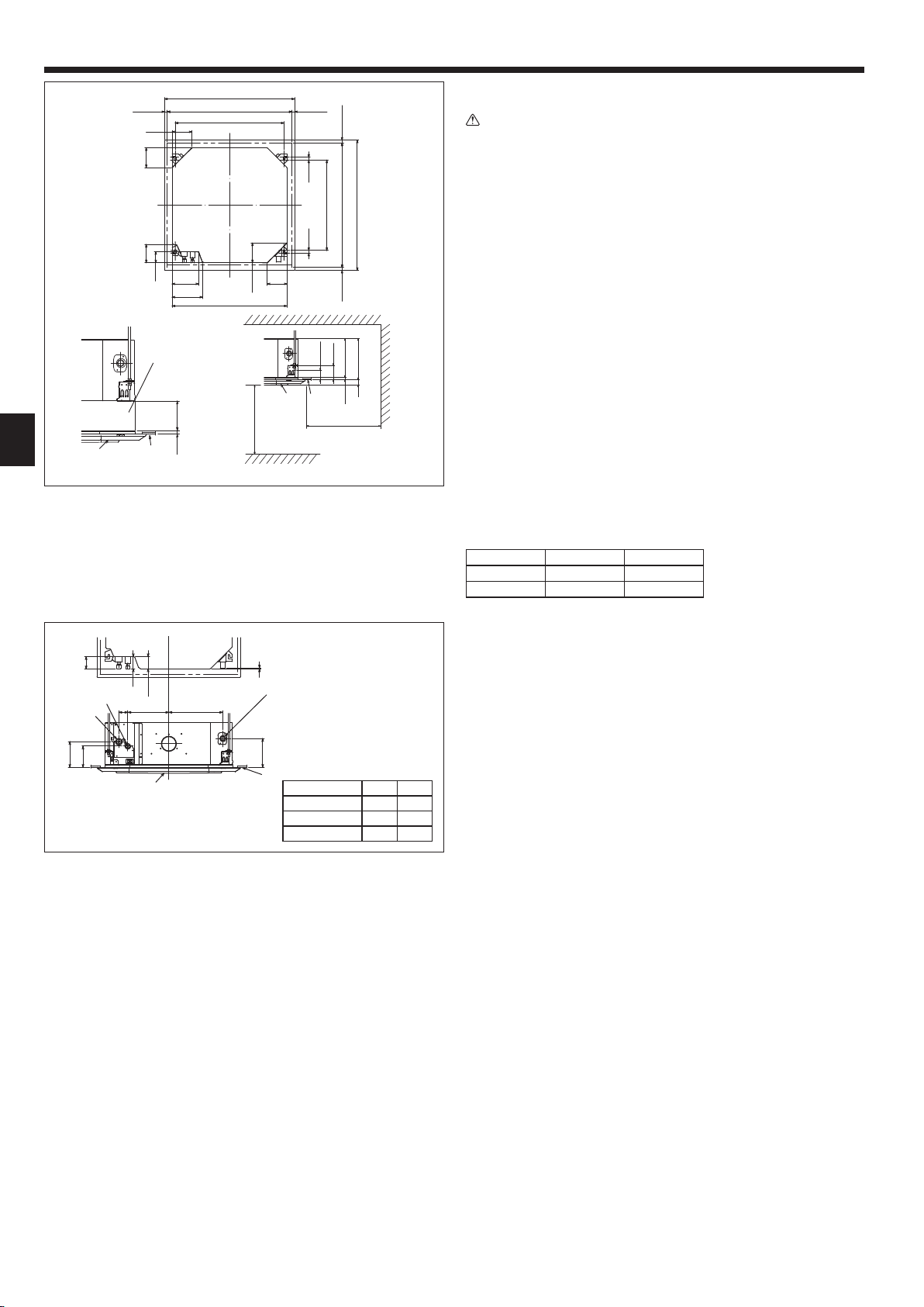
3.2. Ceiling openings and suspension bolt installation
locations (Fig. 3-2)
Warning:
• This unit should be installed in rooms which exceed the oor space specied
in outdoor unit installation manual.
145
(20)
Refer to outdoor unit installation manual.
• Install the indoor unit at least 2.5 m above oor or grade level.
For appliances not accessible to the general public.
• Refrigerant pipes connection shall be accessible for maintenance purposes.
• Using the installation template (top of the package) and the gauge (supplied as an
accessory with the grille), make an opening in the ceiling so that the main unit can
be installed as shown in the diagram. (The method for using the template and the
gauge is shown.)
* Before using, check the dimensions of template and gauge, because they
change due to uctuations of temperature and humidity.
133
79.5
193
222
840 A
145
145
(20)
660 B
950 D
860 – 910 C
20 – 45
* The dimensions of ceiling opening can be regulated within the range shown in
Fig. 3-2; so center the main unit against the opening of ceiling, ensuring that the
respective opposite sides on all sides of the clearance between them becomes
G
E
135
0
+5
F
E
17
Min. 2500
Floor
*50 – 70
F
A
*105
0
+5
17
Min. 1500
H
* B
40
identical.
• Use M10 (3/8") suspension bolts.
* Suspension bolts are to be procured at the eld.
• Install securely, ensuring that there is no clearance between the ceiling panel &
grille, and between the main unit & grille.
A Outer side of main unit E Grille
B Bolt pitch F Ceiling
C Ceiling opening G Multi functional casement (option)
D Outer side of Grille H Entire periphery
* Note that the space between ceiling panel of the unit and ceiling slab, etc. must be
Fig. 3-2
7 mm or more.
* When the optional multi-functional casement is installed, add 135 mm to the
dimensions marked on the gure.
(mm)
Models A B
M35-71 241 258
M100-140 281 298
*170
D
*140
3.3. Refrigerant and drainage piping locations of indoor
F
C
79.5
D
60 357271
E
C
6
A
*190
B
Models C D
M35, 50 76 76.5
M60 80.5 79.5
M71-140 79.5 79.5
(mm)
unit (Fig. 3-3)
The gure marked with * in the drawing represent the dimensions of the main unit
excluding those of the optional multi function casement.
A Drain pipe
B Ceiling
C Grille
D Refrigerant pipe (liquid)
E Refrigerant pipe (gas)
F Main unit
* When the optional multi-functional casement is installed, add 135 mm to the
dimensions marked on the gure.
Fig. 3-3
4
Page 5
3. Installing the indoor unit
A
C
E
70°
B
A
90 100 100 90
D
A
F
*167
*155
I
350
H
Fig. 3-4
A
C
B
1 2
G
D E
D Ceiling
E Rafter
F Beam
G Roof beam
F
660
795
Fig. 3-5
A Suspension bolt (procure locally)
A
B Ceiling
C Nut
D Washer (with insulation)
B
E Mounting plate
F Washer (without insulation)
G Check using the Installation gauge
A
C
D
Min. 30
E
)
240
F
+5
0
C
G
17
(
105
B
Fig. 3-6
A
B
C
Fig. 3-8
P
F
A
O
A
J
K
120°
100
130
*158
G
A Main unit
B Grille
C Pillar
J
H
H Use inserts rated at 100 - 150 kg
each (procure locally)
I Suspension bolts M10 (3/8”)
(procure locally)
J Steel reinforcing rod
I
A
+5
0
A=17
B
D
C
A Main unit
B Ceiling
C Gauge
D Ceiling opening dimensions
Fig. 3-7
A Main unit
B Ceiling
C Installation template
(top of the package)
N
L
120°
M
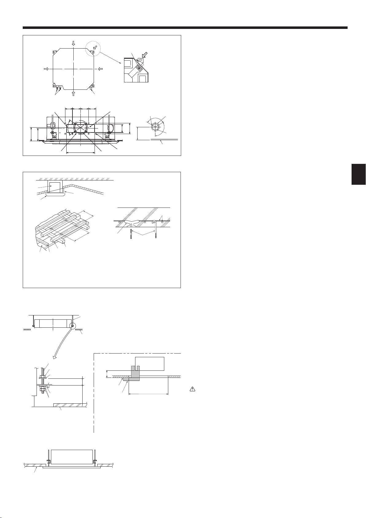
3.4. Branch duct hole and fresh air intake hole (Fig. 3-4)
At the time of installation, use the duct holes (cut out) located at the positions shown
in Fig. 3-4, as and when required.
• A fresh air intake hole for the optional multi function casement can also be made.
Note:
• The gure marked with * in the drawing represent the dimensions of the main
unit excluding those of the optional multi function casement.
• When installing the optional multi function casement, add 135 mm to the
dimensions marked on the gure.
• When installing the branch ducts, be sure to insulate adequately. Otherwise
condensation and dripping may occur.
• When installing the fresh air intake hole, be sure to remove the insulator P
that is pasted on the indoor unit.
• When external air is input directly through the main unit, intake-air volume
should be 5% or less of indoor unit air volume.
• To input the external air, the duct fan and dust collecting lter to prevent
drawing in dust and other particles are necessary.
For details, see “Fresh air intake volume & static pressure characteristics”
in the P series DATA BOOK.
• When external air is input into the main unit, the operation noise can be larger.
A Branch duct hole I ø175 burring hole pitch
B Main unit J Fresh air intake hole diagram
C Fresh air intake hole K 3-4×10 tapping screws
D Drain pipe L ø125 burring hole pitch
E Refrigerant pipe M ø100 cut out hole
F Branch duct hole diagram N Ceiling
(view from either side)
G 14-4×10 tapping screws P Insulation
H ø150 cut out hole
Detailed gure of removing the insulator
O
3.5. Suspension structure (Give site of suspension
strong structure) (Fig. 3-5)
• The ceiling work differs according to the construction of the building. Building constructors and interior decorators should be consulted for details.
(1) Extent of ceiling removal: The ceiling must be kept completely horizontal and the
ceiling foundation (framework: wooden slats and slat holders) must be reinforced
in order to protect the ceiling from vibration.
(2) Cut and remove the ceiling foundation.
(3) Reinforce the ends of the ceiling foundation where it has been cut and add ceiling
foundation for securing the ends of the ceiling board.
(4) When installing the indoor unit on a slanted ceiling, attach a pillar between the
ceiling and the grille and set so that the unit is installed horizontally.
1 Wooden structures
• Use tie beams (single storied houses) or second oor beams (2 story houses) as
reinforcing members.
• Wooden beams for suspending air conditioners must be sturdy and their sides must
be at least 6 cm long if the beams are separated by not more than 90 cm and their
sides must be at least 9 cm long if the beams are separated by as much as 180
cm. The size of the suspension bolts should be ø10 (3/8"). (The bolts do not come
with the unit.)
2 Ferro-concrete structures
Secure the suspension bolts using the method shown, or use steel or wooden hangers, etc. to install the suspension bolts.
3.6. Unit suspension procedures (Fig. 3-6)
Suspend the main unit as shown in the diagram.
Figures given in parentheses represent the dimensions in case of installing optional
multi function casement.
1. In advance, set the parts onto the suspension bolts in the order of the washers
(with insulation), washers (without insulation) and nuts (double).
• Fit the washer with cushion so that the insulation faces downward.
• In case of using upper washers to suspend the main unit, the lower washers (with
insulation) and nuts (double) are to be set later.
2. Lift the unit to the proper height of the suspension bolts to insert the mounting
plate between washers and then fasten it securely.
3. When the main unit cannot be aligned against the mounting hole on the ceiling, it
is adjustable owing to a slot provided on the mounting plate.
• Make sure that A is performed within 17 - 22 mm. Damage could result by failing
to adhere to this range. (Fig. 3-7)
Caution:
Use the top half of the box as a protective cover to prevent dust or debris from
getting inside the unit prior to installation of the decorative cover or when applying ceiling materials.
3.7. Conrming the position of main unit and tightening
the suspension bolts (Fig. 3-8)
• Using the gauge attached to the grille, ensure that the bottom of the main unit is
properly aligned with the opening of the ceiling. Be sure to conrm this, otherwise
condensation may form and drip due to air leakage, etc.
• Conrm that the main unit is horizontally levelled, using a level or a vinyl tube lled
with water.
• After checking the position of the main unit, tighten the nuts of the suspension bolts
securely to fasten the main unit.
• The installation template (top of the package) can be used as a protective sheet
to prevent dust from entering the main unit when the grilles are left unattached for
a while or when the ceiling materials are to be lined after installation of the unit is
nished.
* As for the details of tting, refer to the instructions given on the Installation template.
(top of the package)
5
Page 6
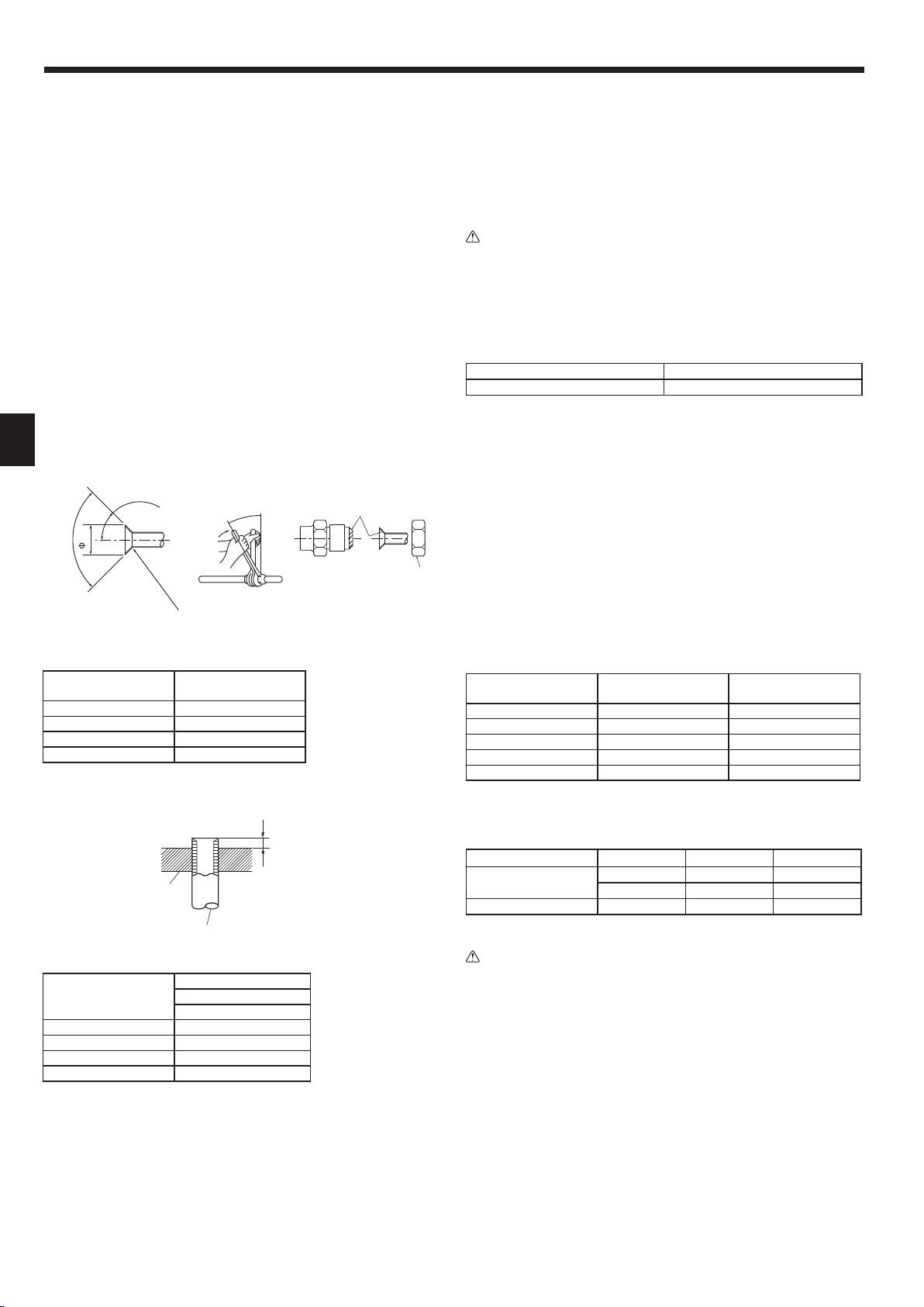
4. Installing the refrigerant piping
A B
90°± 0.5°
A Flare cutting dimensions
Copper pipe O.D.
Copper pipe O.D.
45°± 2°
A
R0.4 - R0.8
Fig. 4-1
(mm)
ø6.35 8.7 - 9.1
ø9.52 12.8 - 13.2
ø12.7 16.2 - 16.6
ø15.88 19.3 - 19.7
Flare dimensions
øA dimensions (mm)
E
F
Fig. 4-2
B (mm)
(mm)
ø6.35 (1/4”) 0 - 0.5
ø9.52 (3/8”) 0 - 0.5
ø12.7 (1/2”) 0 - 0.5
ø15.88 (5/8”) 0 - 0.5
Flare tool for R32/R410A
Clutch type
B
E Die
F Copper pipe
4.1. Precautions
For devices that use R32/R410A refrigerant
• Use alkylbenzene oil (small amount) as the refrigeration oil applied to the
ared sections.
• Use C1220 copper phosphorus for copper and copper alloy seamless pipes,
to connect the refrigerant pipes. Use refrigerant pipes with the thicknesses
specied in the table below. Make sure the insides of the pipes are clean
and do not contain any harmful contaminants such as sulfuric compounds,
oxidants, debris, or dust.
Warning:
When installing or relocating, or servicing the air conditioner, use only the
specied refrigerant written on outdoor unit to charge the refrigerant lines. Do
not mix it with any other refrigerant and do not allow air to remain in the lines.
If air is mixed with the refrigerant, then it can be the cause of abnormal high
pressure in the refrigerant line, and may result in an explosion and other hazards.
The use of any refrigerant other than that specied for the system will cause
mechanical failure or system malfunction or unit breakdown. In the worst case,
this could lead to a serious impediment to securing product safety.
ø6.35 thickness 0.8 mm ø9.52 thickness 0.8 mm
ø12.7 thickness 0.8 mm ø15.88 thickness 1.0 mm
• Do not use pipes thinner than those specied above.
4.2. Connecting pipes (Fig. 4-1)
• When commercially available copper pipes are used, wrap liquid and gas pipes
with commercially available insulation materials (heat-resistant to 100 °C or more,
thickness of 12 mm or more).
C
D
• Apply thin layer of refrigerant oil to pipe and joint seating surface before tightening
are nut.
• Use 2 wrenches to tighten piping connections.
• Use refrigerant piping insulation provided to insulate indoor unit connections. Insulate
carefully.
• After connecting the refrigerant piping to the indoor unit, be sure to test the pipe
connections for gas leakage with nitrogen gas. (Check that there is no refrigerant
leakage from the refrigerant piping to the indoor unit.)
• Use ared nut installed to this indoor unit.
• In case of reconnecting the refrigerant pipes after detaching, make the ared part
of pipe re-fabricated.
B Flare nut tightening torque
Copper pipe O.D.
(mm)
ø6.35 17 14 - 18
ø6.35 22 34 - 42
ø9.52 22 34 - 42
ø12.7 26 49 - 61
ø15.88 29 68 - 82
C Apply refrigerating machine oil over the entire are seat surface.
D Use correct are nuts meeting the pipe size of the outdoor unit.
Available pipe size
Liquid side
Gas side ø12.7 Ο ø15.88 Ο ø15.88 Ο
Ο : Factory are nut attachment to the heat exchanger.
Warning:
• Be careful of ying are nut! (Internally pressurized)
Remove the are nut as follows:
1. Loosen the nut until you hear a hissing noise.
2. Do not remove the nut until the gas has been completely released (i.e.,
hissing noise stops).
3. Check that the gas has been completely released, and then remove the nut.
• When installing the unit, securely connect the refrigerant pipes before starting
the compressor.
Flare nut O.D.
(mm)
M35, 50
ø6.35 Ο ø6.35 —
— ø9.52 Ο ø9.52 Ο
Tightening torque
(N·m)
M60 M71-140
6
Page 7
4. Installing the refrigerant piping
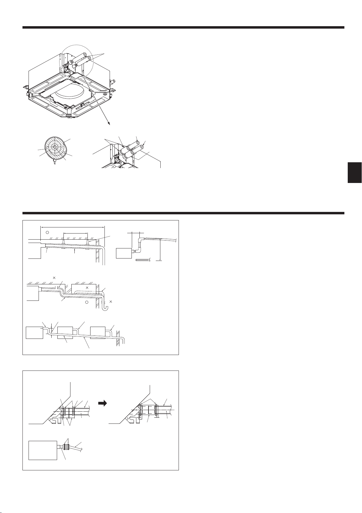
A
A Refrigerant pipe and heat
insulation
B Pipe cover (large)
C Pipe cover (small)
D Refrigerant pipe (gas)
E Refrigerant pipe (liquid)
F Band (large)
G Cross-sectional view of
connection
H Pipe
I Heat insulation
J Squeeze
Heat insulation for refrigerant pipes (Fig. 4-3)
1. Wrap the enclosed large-sized pipe cover around the gas pipe, making sure that
the end of the pipe cover touches the side of the unit.
2. Wrap the enclosed small-sized pipe cover around the liquid pipe, making sure that
the end of the pipe cover touches the side of the unit.
3. Secure both ends of each pipe cover with the enclosed bands. (Attach the bands
20 mm from the ends of the pipe cover.)
4.3. For twin/triple/quadruple combination
Refer to the outdoor unit installation manual.
Some outdoor units cannot be used in a simultaneous twin/triple/quadruple system.
G
F
F
B, C
I
J
H
Fig. 4-3
5. Drainage piping work
1
A
2
3
D
F
Max. 20 m
1.5 - 2 m
B
K
B
E
F F
H
D
I
B
D
E
C
5.1. Drainage piping work (Fig. 5-1)
Max. 15 cm
C
F
J
L
M
D
G
• The indoor parts of the drain pipe should be wrapped with polyethylene foam insula-
tion materials (specic gravity of 0.03, thickness of 9 mm or more).
• Use VP25 (O.D. ø32 PVC TUBE) for drain piping and provide 1/100 or more down-
ward slope.
• Be sure to connect the piping joints using a PVC type adhesive.
• Observe the gure for piping work.
• Use the included drain hose to change the extraction direction.
• When performing the drainage piping work, be sure to use the support metal holders.
If a load is applied to the drain socket that damages the hose or causes the hose
to become detached, water leakage may result.
Correct piping G Make the piping size large for grouped pip-
1
2 Wrong piping
3 Grouped piping H Downward slope (1/100 or more)
A Insulation (9 mm or more) I O.D. ø38 PVC TUBE for grouped piping
B Downward slope (1/100 or more)
C Support metal J Up to 85 cm
D O.D. ø32 PVC TUBE K Air bleeder
E Make it as large as possible
(about 10 cm)
F Main unit
ing.
(9 mm or more insulation)
L Raised
M Odor trap
A AH
C KFF
6
30 30
G
D E
C
J
I
Fig. 5-1
(mm)
Fig. 5-2
1. Connect the drain socket (supplied with the unit) to the drain port. (Fig. 5-2)
(Fix the tube using PVC adhesive then secure it with a band.)
2. Install a locally purchased drain pipe (PVC pipe, O.D. ø32).
(Fix the pipe using PVC adhesive then secure it with a band.)
C
H
7
7
18
B
G
3. Check that drain ows smoothly.
4. Insulate the drain port and socket with insulating material, then secure the material
with a band. (Both insulating material and band are supplied with the unit.)
5. Insulate the tube and pipe. (PVC pipe, O.D. ø32)
Main unit G Drain pipe (O.D. ø32 PVC TUBE)
A
B Insulating material H Insulating material (purchased locally)
C Band (large) I Transparent PVC pipe
D Drain port (transparent) J O.D. ø32 PVC TUBE (Slope 1/100 or more)
E Insertion margin K Drain socket
F Matching
7
Page 8
6. Electrical work
[3]
G
H
J
[4]
K
L
B
[1]
Round crimped terminal
[2]
F
A
D
I
M
N
Fig. 6-1
Fig. 6-2
E
Insulating sleeve
Electrical cable
C
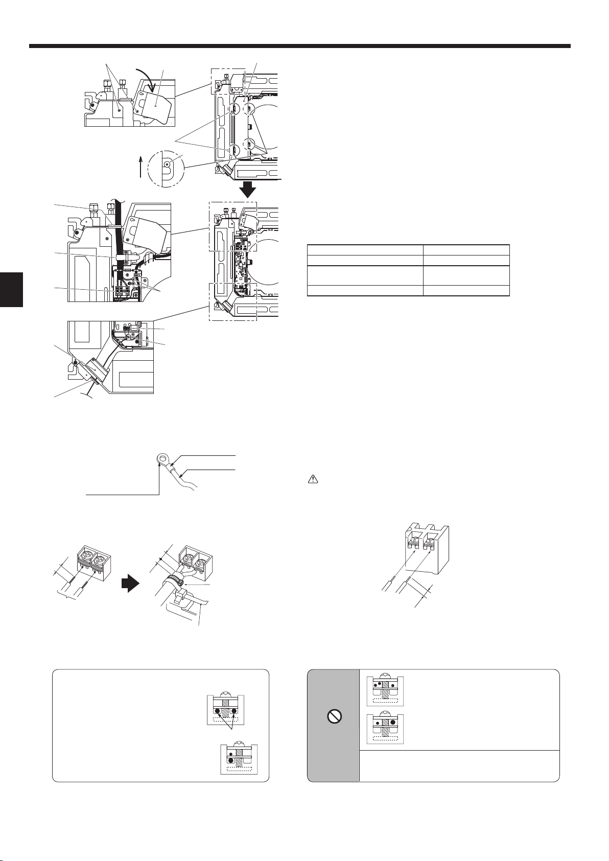
6.1. Indoor unit (Fig. 6-1)
1. Loosen the two screws securing the electrical wiring service panel, and then turn
the electrical wiring service panel. [Fig. 6-1 1]
2. Loosen the two screws securing the electrical box cover, then slide the electrical
box cover. [Fig. 6-1 2]
3. Pass the power cable, indoor/outdoor unit connecting cable and earth cable through
the wiring entries given in the diagram. [Fig. 6-1 3]
Put the sheath portion of the power cable and indoor/outdoor connecting cable
into the electrical box.
Use round crimped terminals for the indoor-outdoor connection terminal and the
optional power supply terminal kit. [Fig. 6-2]
If you cannot use round crimped terminals, following the procedure in Fig. 6-3 to
6-6.
Refer to 6.1.1. and 6.1.2. for the connection.
4. Pass and wire the remote controller cable through the wiring entries given in the
diagram. [Fig. 6-1 4, Fig. 6-3]
Refer to 6.1.1. and 6.1.2. for the connection.
• Do not allow slackening of the terminal screws.
Screw tightening torque
Tightening torque (N·m)
Remote controller terminal board 1.2 ± 0.1
Indoor-outdoor connection termi-
nal board
Earth cable 1.6 ± 0.1
• Leave excess cable so that the electrical box can be suspended below the unit
during servicing (approx. 50 to 100 mm).
Electrical wiring service panel
A
B Screw
C Electrical box cover
D Temporary hook for electrical box cover
E Screw
F Slide direction of the electrical box cover
G Entry for power cable and indoor/outdoor unit connecting cable
H Secure with the cable strap.
I Earth cable
J Indoor/outdoor unit connecting terminal
K Electrical wiring service panel (remote controller)
L Entry for wired remote controller
M Wired remote controller terminal
N Secure with the cable strap.
Caution:
• Wiring for remote controller cable shall be apart (5 cm or more) from power
source wiring so that it is not inuenced by electric noise from power source
wiring.
1.6 ± 0.1
12
Be sure to connect the remote
controller cable (0.3 mm²) to the
locations shown in the diagram.
<When wiring two indoor-outdoor connection cables>
• If the cables have the same diameter,
insert them into the cut outs on both sides.
• If the cables have different diameters, insert them on one side into separate spaces
with one cable positioned above the other.
8
1510
Secure with a band 4 (small)
at the location shown in the
Fig. 6-3
(Remote controller
cable retainer)
Cable strap
diagram
Cut outs
• The U-shaped groove opens if you push the screw head after the screw is loosened.
WARNING
When using a single cable, a round crimped terminal or other
terminal work is prohibited.
12
Fig. 6-4
• Connecting two wires on one side is prohibited.
• Connecting three wires or more to the same
terminal is prohibited.
• Connecting wires with different diameters is
prohibited.
Fig. 6-5 Fig. 6-6
Page 9
6. Electrical work
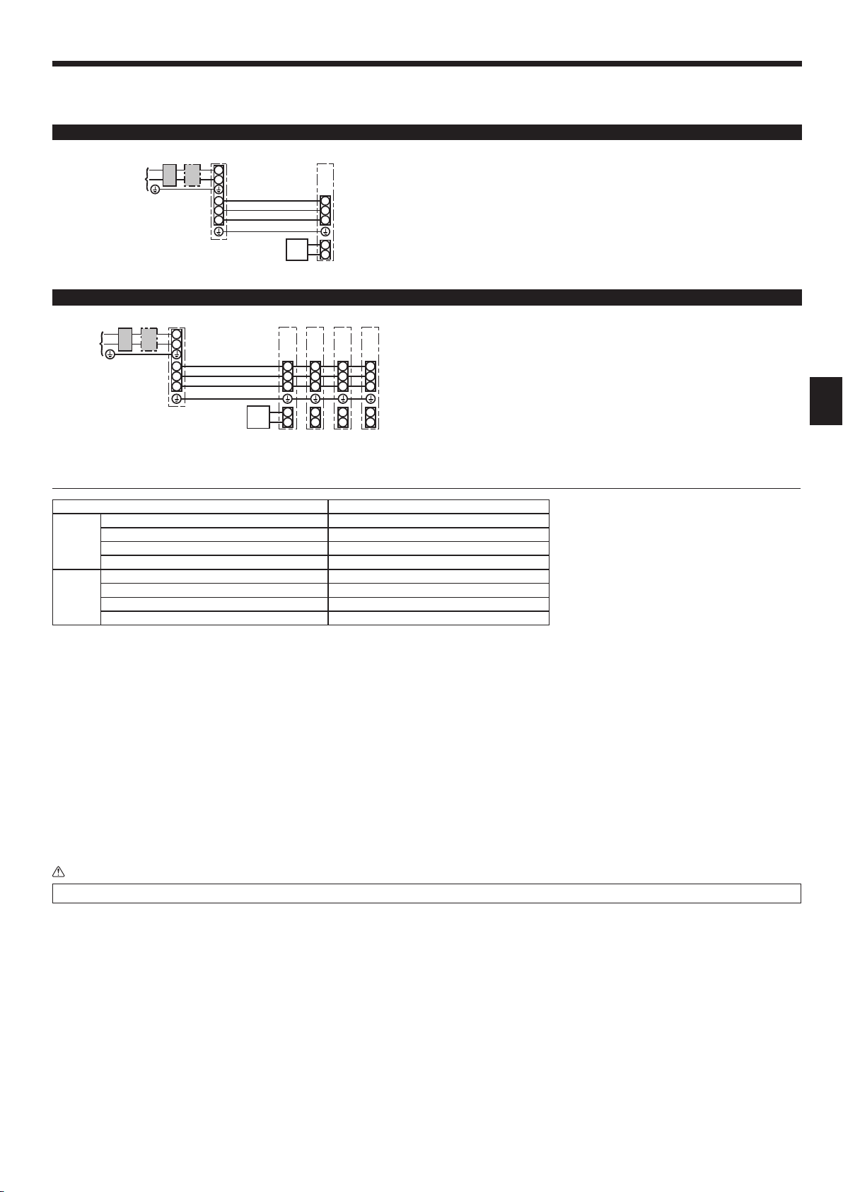
6.1.1. Indoor unit power supplied from outdoor unit
The following connection patterns are available.
The outdoor unit power supply patterns vary on models.
1:1 System
D
B C
A
L
N
S1
S2
S3
E
* Afx label A that is included with the manuals near each wiring diagram for the indoor and outdoor units.
D
B C
A
L
N
S1
S2
S3
E
F
* Afx label A that is included with the manuals near each wiring diagram for the indoor and outdoor units.
Note:
Some units cannot be used in a simultaneous twin/triple/quadruple system. Refer to the outdoor unit installation manual for details.
G
S1
S2
S3
1
F
2
A Outdoor unit power supply
B Earth leakage breaker
C Wiring circuit breaker or isolating switch
D Outdoor unit
E Indoor unit/outdoor unit connecting cables
F Remote controller
G Indoor unit
Simultaneous twin/triple/quadruple system
G G G G
S1
S1
S2
S3
1
2
S1
S2
S2
S3
S3
1
1
2
2
S1
S2
S3
1
2
A Outdoor unit power supply
B Earth leakage breaker
C Wiring circuit breaker or isolating switch
D Outdoor unit
E Indoor unit/outdoor unit connecting cables
F Remote controller
G Indoor unit
Indoor unit model PLA
Indoor unit-Outdoor unit *1 3 × 1.5 (polar)
)
2
Indoor unit-Outdoor unit earth *1 1 × Min. 1.5
Indoor unit earth 1 × Min. 1.5
(mm
No. × size
Remote controller-Indoor unit *2 2 × 0.3 (Non-polar)
Wiring Wire
Indoor unit (Heater) L-N —
Indoor unit-Outdoor unit S1-S2 *3 230 VAC
Indoor unit-Outdoor unit S2-S3 *3 24 VDC
rating
Circuit
Remote controller-Indoor unit *3 12 VDC
*1. <For 35-140 outdoor unit application>
Max. 45 m
If 2.5 mm
If 2.5 mm
<For 200/250 outdoor unit application>
Max. 18 m
If 2.5 mm
If 4 mm
If 6 mm
*2. Max. 500 m
(When using 2 remote controllers, the maximum wiring length for the remote controller cables is 200 m.)
*3. The gures are NOT always against the ground.
S3 terminal has 24 VDC against S2 terminal. However between S3 and S1, these terminals are not electrically insulated by the transformer or other device.
2
used, Max. 50 m
2
used and S3 separated, Max. 80 m
2
used, Max. 30 m
2
used and S3 separated, Max. 50 m
2
used and S3 separated, Max. 80 m
Notes: 1. Wiring size must comply with the applicable local and national code.
2.
3. Install an earth longer than other cables.
Power supply cords and indoor unit/outdoor unit connecting cords shall not be lighter than polychloroprene sheathed exible cord. (Design 60245 IEC 57)
4. Indoor and outdoor connecting wires have polarities. Make sure to match the terminal number (S1, S2, S3) for correct wirings.
5. Wiring for remote controller cable shall be apart (5 cm or more) from power source wiring so that it is not inuenced by electric noise from power
source wiring.
Warning:
Never splice the power cable or the indoor-outdoor connection cable, otherwise it may result in a smoke, a re or communication failure.
9
Page 10
6. Electrical work
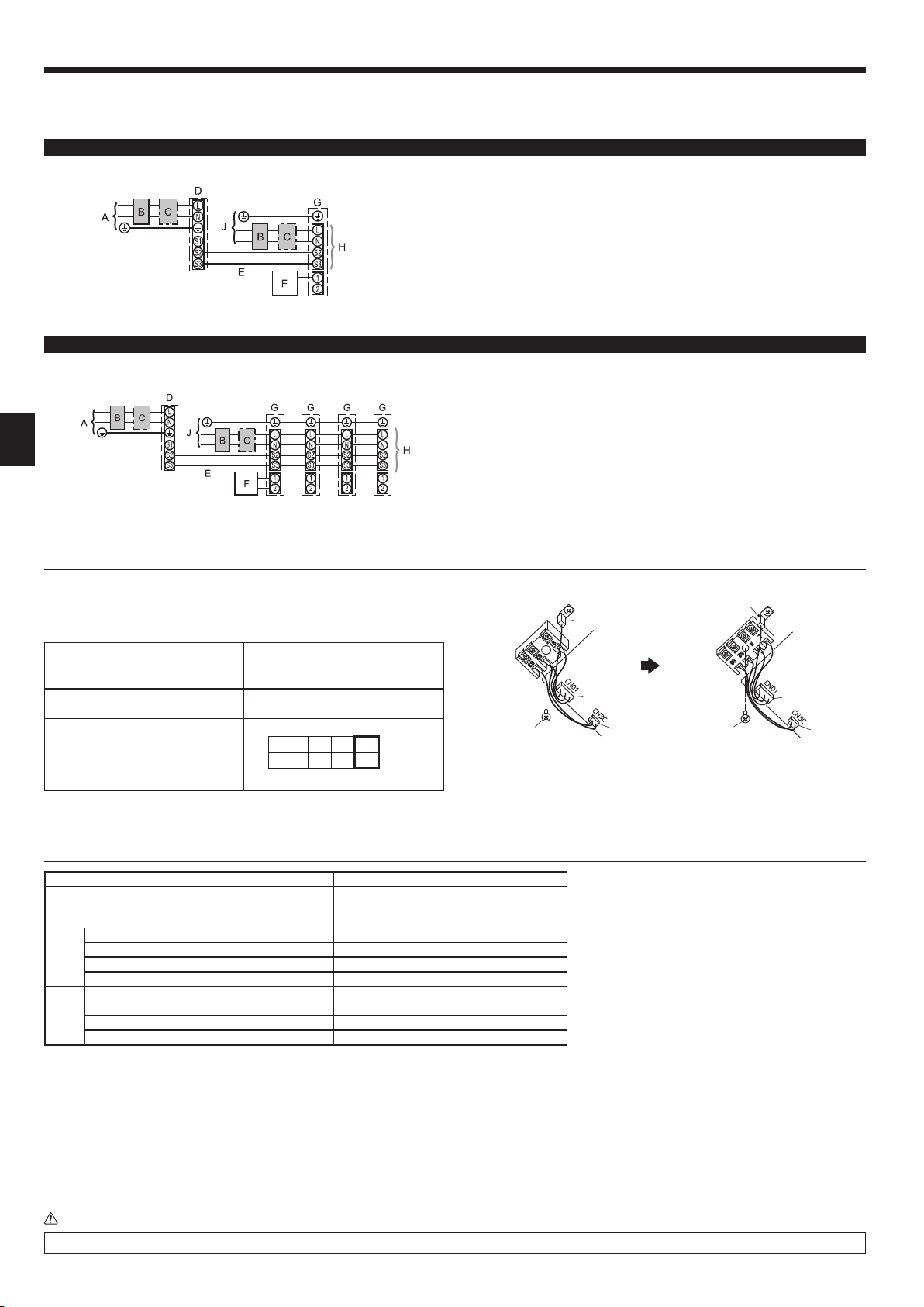
6.1.2. Separate indoor unit/outdoor unit power supplies (For PUHZ/PUZ application only)
The following connection patterns are available.
The outdoor unit power supply patterns vary on models.
1:1 System
* The indoor power supply terminal kit is required.
* Afx label B that is included with the manuals near each wiring diagram for the indoor and outdoor units.
Simultaneous twin/triple/quadruple system
* The indoor power supply terminal kits are required.
A Outdoor unit power supply
B Earth leakage breaker
C Wiring circuit breaker or isolating switch
D Outdoor unit
E Indoor unit/outdoor unit connecting cables
F Remote controller
G Indoor unit
H Option
J Indoor unit power supply
A Outdoor unit power supply
B Earth leakage breaker
C Wiring circuit breaker or isolating switch
D Outdoor unit
E Indoor unit/outdoor unit connecting cables
F Remote controller
G Indoor unit
H Option
J Indoor unit power supply
* Afx label B that is included with the manuals near each wiring diagram for the indoor and outdoor units.
Note:
Some units cannot be used in a simultaneous twin/triple/quadruple system. Refer to the outdoor unit installation manual for details.
If the indoor and outdoor units have separate power supplies, refer to the table below.
If the indoor power supply terminal kit is used, change the indoor unit electrical box
wiring refering to the gure in the right and the DIP switch settings of the outdoor
unit control board.
<Replacing the indoor unit terminal block>
2
3
Indoor power supply terminal kit (option) Required
Indoor unit electrical box connector
connection change
Label afxed near each wiring diagram
for the indoor and outdoor units
Outdoor unit DIP switch settings (when
using separate indoor unit/outdoor unit
power supplies only)
Set the SW8-3 to ON.
* There are 3 types of labels (labels A, B and C). Afx the appropriate labels to the
units according to the wiring method.
Indoor unit model PLA
Indoor unit power supply ~/N (single), 50 Hz, 230 V
Indoor unit input capacity
Main switch (Breaker)
)
Indoor unit power supply & earth 3 × Min. 1.5
2
Indoor unit-Outdoor unit *2 2 × Min. 0.3
Indoor unit-Outdoor unit earth –
Wiring
size (mm
Wire No. ×
Remote controller-Indoor unit *3 2 × 0.3 (Non-polar)
Indoor unit L-N *4 230 VAC
Indoor unit-Outdoor unit S1-S2 –
Indoor unit-Outdoor unit S2-S3 *4 24 VDC
rating
Circuit
Remote controller-Indoor unit *4 12 VDC
*1. A breaker with at least 3.0 mm contact separation in each pole shall be provided. Use earth leakage breaker (NV).
The breaker shall be provided to ensure disconnection of all active phase conductors of the supply.
*2. Max. 120 m
*3. Max. 500 m
(When using 2 remote controllers, the maximum wiring length for the remote controller cables is 200 m.)
*4. The gures are NOT always against the ground.
Required
Required
ON
OFF 1 2
*1 16 A
2
3
(SW8)
1 Disconnect connector CN3C (blue) from
the indoor controller board.
2 Disconnect connector CN01 (black) from
the indoor controller board.
3 Disconnect the tab terminal.
4 Remove the screw from the terminal block.
4
1
1
Install the optional Power supply terminal kit.
Refer to the installation manual that comes
with the optional Power supply terminal kit
for details.
1 Secure the terminal block with the screw.
2 Insert the tab terminal.
3 Connect connector CN01 (black) to the
indoor controller board.
4 Connect connector CN3C (blue) to the
indoor controller board.
3
4
Notes: 1. Wiring size must comply with the applicable local and national code.
2. Power supply cords and indoor unit/outdoor unit connecting cords shall not be lighter than polychloroprene sheathed exible cord.
(Design 60245 IEC 57)
3. Install an earth longer than other cables.
4. Wiring for remote controller cable shall be apart (5 cm or more) from power source wiring so that it is not inuenced by electric noise from power
source wiring.
Warning:
Never splice the power cable or the indoor-outdoor connection cable, otherwise it may result in a smoke, a re or communication failure.
10
Page 11
6. Electrical work
1
B
C
A
2
D
Fig. 6-7
B
A
Fig. 6-8
1
7
4
2
3
6
5
8
C
A
B
Fig. 6-9 Fig. 6-10
6.2. Remote controller
6.2.1. For wired remote controller
1) 2 remote controllers setting
If 2 remote controllers are connected, set one to “Main” and the other to “Sub”.
For setting procedures, refer to “Function selection of remote controller” in the
operation manual for the indoor unit.
6.2.2. For wireless remote controller
1) Installation area
• Area in which the remote controller is not exposed to direct sunshine.
• Area in which there is no nearby heating source.
• Area in which the remote controller is not exposed to cold (or hot) winds.
• Area in which the remote controller can be operated easily.
• Area in which the remote controller is beyond the reach of children.
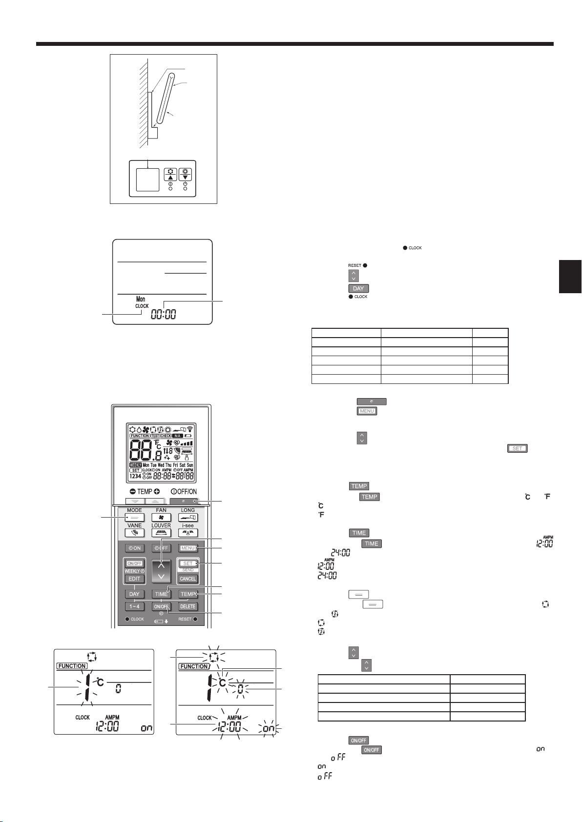
2) Installation method (Fig. 6-7)
1 Attach the remote controller holder to the desired location using 2 tapping
screws.
2 Place the lower end of the controller into the holder.
A Remote controller B Wall C Display panel D Receiver
• The signal can travel up to approximately 7 meters (in a straight line) within
45 degrees to both right and left of the center line of the receiver.
3) Setting (Clock setting) (Fig. 6-8)
1 Insert batteries or press the
[CLOCK] A and [:] B blinks.
2 Press the
3 Press the
Press the
4 Press the
[CLOCK] and [:] lighted.
4) Initial setting
The following settings can be made in the initial setting mode.
Temperature unit ºC/ºF
Time display 12-hour format/24-hour format
AUTO mode Single set point/Dual set point
Pair No. 0–3
Backlight On/Off
4-1. Switching to the initial setting mode
1. Press the
2. Press the
The Function setting screen will be displayed and the function No. A will
blink. (Fig. 6-9)
Press the
3. Check that function No. “1” is displayed, and then press the
3.
The display setting screen will be displayed. (Fig. 6-10)
4-2. Changing the temperature unit A
Press the
Each time the button 5 is pressed, the setting switches between and .
: The temperature is displayed in degrees Celsius.
: The temperature is displayed in degrees Fahrenheit.
4-3. Changing the time display B
Press the
Each time the
and
: The time is displayed in the 12-hour format.
: The time is displayed in the 24-hour format.
4-4. Changing the AUTO mode C
Press the
Each time the
and
: The AUTO mode operates as the usual automatic mode.
: The AUTO mode operates using dual set points.
4-5. Changing the pair No. D
Press the button 4.
Each time the
A
Pair No. of wireless remote controller Indoor PC board
D
E
4-6. Changing the backlight setting E
Press the
Each time the
and
: The backlight comes on when a button is pressed.
: The backlight does not come on when a button is pressed.
button with something sharp.
button to set the time.
button to set the Day.
button with something sharp at the end.
Item Setting Fig. 6-10
button 1 to stop the air conditioner.
button 2.
button 4 to change the function No.
button 5.
button 6.
button 6 is pressed, the setting switches between
.
button 7.
button 7 is pressed, the setting switches between
.
button 4 is pressed, the pair No. 0–3 changes.
0 Initial setting
1 Cut J41
2 Cut J42
3 Cut J41, J42
button 8.
button 8 is pressed, the setting switches between
.
button with something sharp.
A
B
C
D
E
button
11
Page 12
6. Electrical work
Service menu
Test run
Input maintenance info.
Function setting
Check
Self check
Main menu:
Cursor
F1 F2 F3 F4
Ref. address
Unit No.
Monitor:
F1 F2 F3 F4
Fig. 6-11 Fig. 6-12
Function setting
Ref. address
Mode 1
Mode 2
Mode 3
Mode 4
Request:
Cursor Cursor
F1 F2 F3 F4
Grp.
Ref. address
Mode 7
Mode 8
Mode 9
Mode 10
Request:
F1 F2 F3 F4
Fig. 6-13 Fig. 6-14
Function setting
Ref. address
Grp.
Function setting
Grp./1/2/3/4/All
Cursor Address
Function setting
Cursor Cursor
Unit # 1
6.3. Function settings
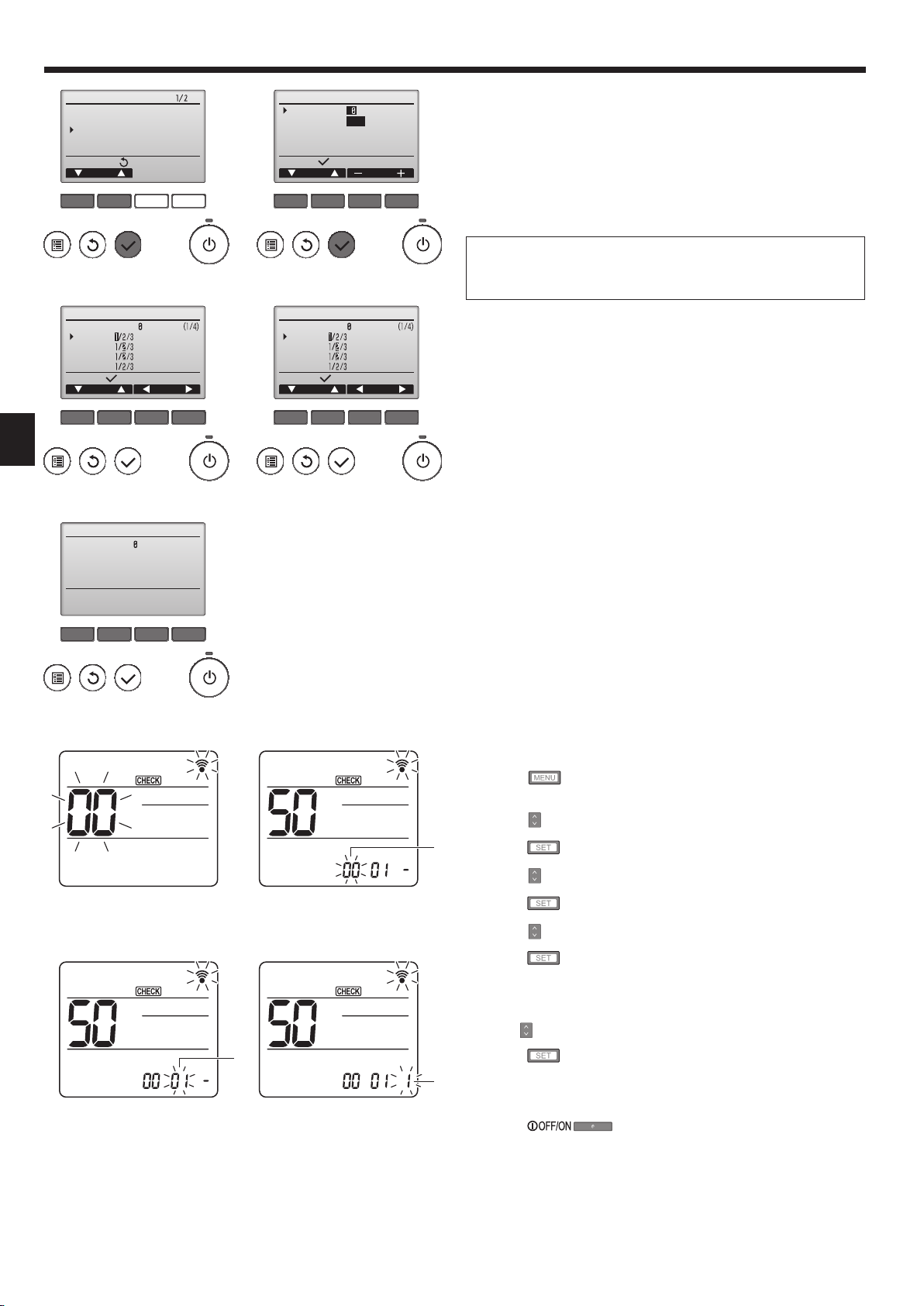
6.3.1. By wired remote controller
1 (Fig. 6-11)
• Select “Service” from the Main menu, and press the [SELECT] button.
• Select “Function settings” with the [F1] or [F2] button, and press the [SELECT]
button.
2 (Fig. 6-12)
• Set the indoor unit refrigerant addresses and unit numbers with the [F1] through
[F4] buttons, and then press the [SELECT] button to con rm the current setting.
<Checking the Indoor unit No.>
When the [SELECT] button is pressed, the target indoor unit will start fan operation.
If the unit is common or when running all units, all indoor units for the selected
refrigerant address will start fan operation.
3 (Fig. 6-13)
• When data collection from the indoor units is completed, the current settings
appears highlighted. Non-highlighted items indicate that no function settings are
made. Screen appearance varies depending on the “Unit No.” setting.
4 (Fig. 6-14)
• Use the [F1] or [F2] button to move the cursor to select the mode number, and
change the setting number with the [F3] or [F4] button.
5 (Fig. 6-15)
• When the settings are completed, press the [SELECT] button to send the setting
data from the remote controller to the indoor units.
• When the transmission is successfully completed, the screen will return to the
Function setting screen.
Sending data
F1 F2 F3 F4
Fig. 6-15
Fig. 6-16
Fig. 6-18
6.3.2. By wireless remote controller
1 Going to the function select mode
Press the
(Start this operation from the status of remote controller display turned off.)
[CHECK] is lighted and "00" blinks. (Fig. 6-16)
Press the
Direct the wireless remote controller toward the receiver of the indoor unit and
press the
A
2 Setting the unit number
Press the
Direct the wireless remote controller toward the receiver of the indoor unit and
Fig. 6-17
B
Fig. 6-19
press the
3 Select a mode
Press the
Direct the wireless remote controller toward the receiver of the indoor unit and
press the
Current setting number: 1=1 beep (1 second)
2=2 beep (1 second each)
3=3 beep (1 second each)
4 Selecting the setting number
Use the
Direct the wireless remote controller toward the receiver of the indoor unit and
press the
5 To select multiple functions continuously
C
Repeat select 3 and 4 to change multiple function settings continuously.
6 Complete function selection
Direct the wireless remote controller toward the sensor of the indoor unit and
press the
button between of 5 seconds.
button to set the "50".
button.
button to set unit number A. (Fig. 6-17)
button.
button to set Mode number B. (Fig. 6-18)
button.
button to change the Setting number C. (Fig. 6-19)
button.
button.
12
Note:
Make the above settings on Mr. Slim units as necessary.
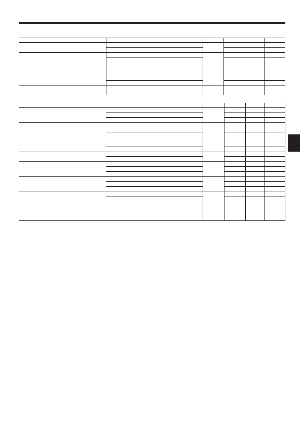
• Table 1 summarizes the setting options for each mode number.
• Be sure to write down the settings for all functions if any of the initial set-
tings has been changed after the completion of installation work.
Page 13
6. Electrical work
Function table (Table 1)
Select unit number 00
Mode Settings Mode no. Setting no.
Power failure automatic recovery Not available
Indoor temperature detecting Indoor unit operating average
LOSSNAY connectivity Not Supported
Power voltage 240 V
Select unit numbers 01 to 03 or all units (AL [wired remote controller]/07 [wireless remote controller])
Mode Settings Mode no. Setting no.
Filter sign 100 Hr
Fan speed Silent (low ceiling)
No. of air outlets 4 directions
Installed options (high efciency lter) Not supported
Up/down vane setting
3D i-see Sensor positioning
3D i-see Sensor ceiling height setting
(when installing the 3D i-see Sensor panel)
Fan speed during the cooling thermostat is OFF Setting fan speed
*1 When the power supply returns, the air conditioner will start 3 minutes later.
*2 Power failure automatic recovery initial setting depends on the connecting outdoor unit.
*3 When the 3D i-see Sensor corner panel position is changed, change this mode. Refer to page 19.
Available *1 2 Ο *2
Set by indoor unit’s remote controller 2
Remote controller’s internal sensor 3
Supported (indoor unit is not equipped with outdoor-air
intake)
Supported (indoor unit is equipped with outdoor-air intake) 3
220 V, 230 V 2 Ο
2500 Hr 2 Ο
No lter sign indicator 3
Standard 2 Ο
High ceiling 3
3 directions 2
2 directions 3
Supported 2
Downward setting (vanes angle setup 3)
Middle setting (vanes angle setup 1)
Draft - less setting (vanes angle setup 2)
Position 1
Position 2
Position 3 (Default)
Low ceiling (ceiling height: less than 2.7 m)
Standard (ceiling height: 2.7 – 3.5 m) 2 Ο
High ceiling (ceiling height: 3.5 – 4.5 m) 3
Stop 2
Extra low 3 Ο
01
02
03
04
07
08
09
10
11
12 *3
26
27
1
1 Ο
1 Ο
2
1
1
1
1 Ο
1 Ο
1
2
3 Ο
1
2
3 Ο
1
1
Initial setting
Initial setting
setting
setting
13
Page 14
7. Test run
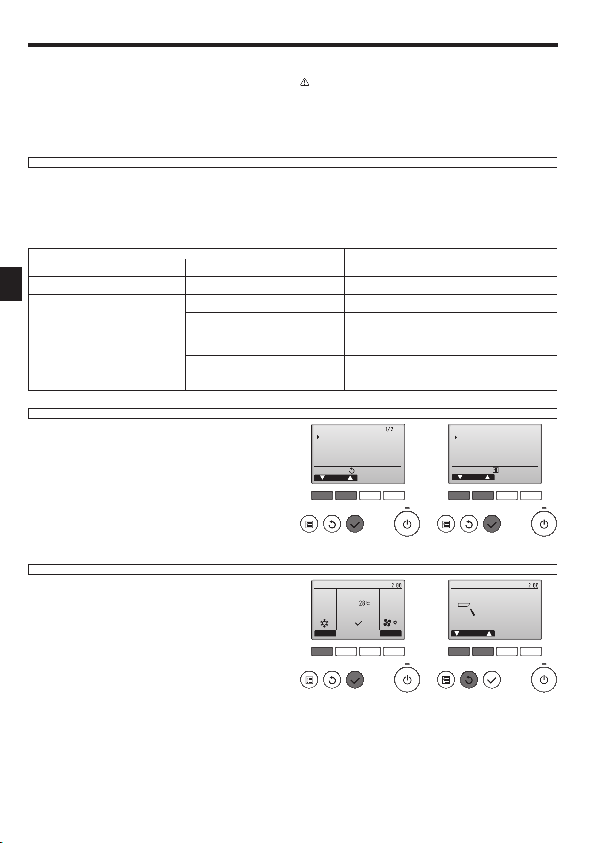
7.1. Before test run
► After completing installation and the wiring and piping of the indoor and
outdoor units, check for refrigerant leakage, looseness in the power supply
or control wiring, wrong polarity, and no disconnection of one phase in the
supply.
► Use a 500-volt megohmmeter to check that the resistance between the power
supply terminals and ground is at least 1.0 MΩ.
7.2. Test run
7.2.1. Using wired remote controller.
■ Make sure to read operation manual before test run. (Especially items to secure safety)
Step 1 Turn on the power.
● Remote controller: The system will go into startup mode, and the remote controller power lamp (green) and “PLEASE WAIT” will blink. While the lamp and message are
blinking, the remote controller cannot be operated. Wait until “PLEASE WAIT” is not displayed before operating the remote controller. After the power is turned on, “PLEASE
WAIT” will be displayed for approximately 3 minutes.
● Indoor controller board: LED 1 will be lit up, LED 2 will be lit up (if the address is 0) or off (if the address is not 0), and LED 3 will blink.
● Outdoor controller board: LED 1 (green) and LED 2 (red) will be lit up. (After the startup mode of the system nishes, LED 2 will be turned off.) If the outdoor controller
board uses a digital display, [- ] and [ -] will be displayed alternately every second.
If the operations do not function correctly after the procedures in step 2 and thereafter are performed, the following causes should be considered and eliminated if they
are found.
(The symptoms below occur during the test run mode. “Startup” in the table means the LED display written above.)
Symptoms in test run mode
Remote Controller Display
Remote controller displays “PLEASE WAIT”, and
cannot be operated.
After power is turned on, “PLEASE WAIT” is displayed for 3 minutes, then error code is displayed.
No display appears even when remote controller
operation switch is turned on. (Operation lamp
does not light up.)
Display appears but soon disappears even when
remote controller is operated.
OUTDOOR BOARD LED Display
< > indicates digital display.
After “startup” is displayed, only green lights
up. <00>
After “startup” is displayed, green (once) and red
(once) blink alternately. <F1>
After “startup” is displayed, green (once) and red
(twice) blink alternately. <F3, F5, F9>
After “startup” is displayed, green (twice) and red
(once) blink alternately. <EA. Eb>
After “startup” is displayed, only green lights
up. <00>
After “startup” is displayed, only green lights
up. <00>
► Do not carry out this test on the control wiring (low voltage circuit) terminals.
Warning:
Do not use the air conditioner if the insulation resistance is less than 1.0 MΩ.
Cause
• After power is turned on, “PLEASE WAIT” is displayed for 3
minutes during system startup. (Normal)
• Incorrect connection of outdoor terminal block (R, S, T and S
S
, S3.)
2
1
• Outdoor unit’s protection devise connector is open.
• Incorrect wiring between the indoor and outdoor unit (Polarity is
wrong for S
• Remote controller transmission wire short.
• There is no outdoor unit of address 0. (Address is other than 0.)
• Remote controller transmission wire open.
• After canceling function selection, operation is not possible for
about 30 seconds. (Normal)
, S2, S3.)
1
,
Step 2 Switch the remote controller to “Test run”.
1 Select “Test run” from the Service menu, and press the [SELECT] button. (Fig. 7-1)
2 Select “Test run” from the Test run menu, and press the [SELECT] button. (Fig. 7-2)
3 The test run operation starts, and the Test run operation screen is displayed.
Step 3 Perform the test run and check the airow temperature and auto vane.
1 Press the [F1] button to change the operation mode. (Fig. 7-3)
Cooling mode: Check that cool air blows from the unit.
Heating mode: Check that warm air blows from the unit.
2 Press the [SELECT] button to display the Vane operation screen, and then press
the [F1] and [F2] buttons to check the auto vane. (Fig. 7-4)
Press the [RETURN] button to return to the Test run operation screen.
Test run
Input maintenance info.
Function setting
Check
Self check
unem ecivreS
:unem niaM
rosruC
F1 F2 F3 F4
Fig. 7-1
RemainTest run
Pipe
Cool
Switch disp.
Mode Fan
Auto
F1 F2 F3 F4
Fig. 7-3
Test run menu
Test run
Drain pump test run
Service menu:
Cursor
F1 F2 F3 F4
Fig. 7-2
Remain
Vane
F1 F2 F3 F4
Fig. 7-4
14
Page 15
7. Test run
Step 4 Conrm the operation of the outdoor unit fan.
The speed of the outdoor unit fan is controlled in order to control the performance of the unit. Depending on the ambient air, the fan will rotate at a slow speed and will keep
rotating at that speed unless the performance is insufcient. Therefore, the outdoor wind may cause the fan to stop rotating or to rotate in the opposite direction, but this is
not a problem.
Step 5 Stop the test run.
1 Press the [ON/OFF] button to stop the test run. (The Test run menu will appear.)
Note: If an error is displayed on the remote controller, see the table below.
LCD Description of malfunction LCD Description of malfunction LCD Description of malfunction
P1 Intake sensor error P9 Pipe sensor error (dual-wall pipe)
P2 Pipe sensor error (liquid pipe) PA Leakage error (refrigerant system)
Drain oat switch connector
P4
disconnected (CN4F)
Pb Indoor unit fan motor error
PL Refrigerant circuit abnormal
E0 – E5
P5 Drain overow protection operation FB Indoor controller board error
Freezing/overheating protection
P6
operation
P8 Pipe temperature error
U*, F*
(* indicates an
alphanumeric
character
excluding FB.)
Outdoor unit malfunction
Refer to the wiring diagram for the
outdoor unit.
E6 – EF
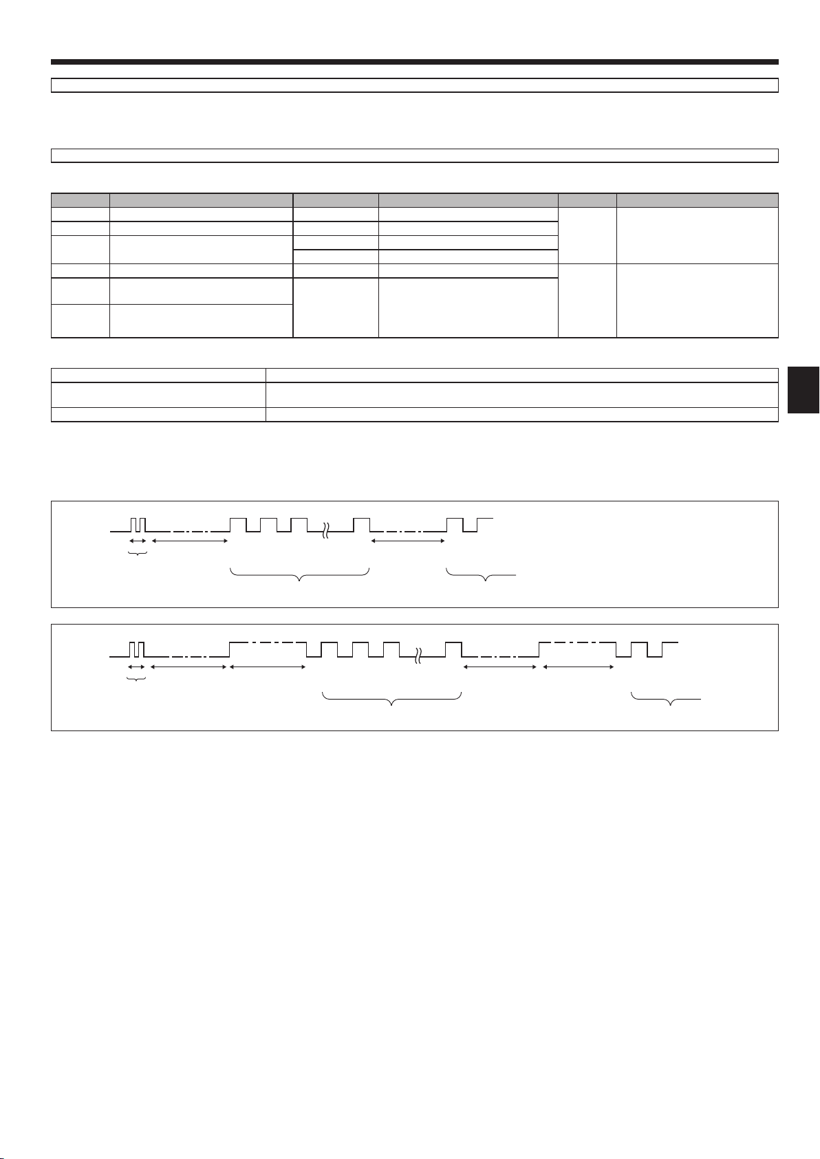
See the table below for the details of the LED display (LED 1, 2, and 3) on the indoor controller board.
LED 1 (microcomputer power supply) Indicates whether control power is supplied. Make sure that this LED is always lit.
LED 2 (remote controller power supply)
Indicates whether power is supplied to the wired remote controller. The LED is lit only for the indoor unit that is connected
to the outdoor unit that has an address of 0.
LED 3 (indoor/outdoor unit communication) Indicates whether the indoor and outdoor units are communicating. Make sure that this LED is always blinking.
Communication error between the
remote controller and the indoor
unit
Communication error between the
indoor unit and the outdoor unit
7.3. Self-check
■ Refer to the installation manual that comes with each remote controller for details.
• Refer to the following tables for details on the check codes. (Wireless remote controller)
[Output pattern A]
Beeper sounds
OPERATION
INDICATOR
lamp blinking
pattern
[Output pattern B]
Beeper sounds
OPERATION
INDICATOR
lamp blinking
pattern
Beep
Off
Self-check
starts
(Start signal
received)
Self-check
starts
(Start signal
received)
Approx. 2.5 sec.On0.5 sec.On0.5 sec.On0.5 sec.
Beep Beep Beep Beep Beep Beep Beep
Off
Approx. 2.5 sec.OnApprox. 3 sec.On0.5 sec.On0.5 sec.On0.5 sec.
Beep Beep Beep Beep Beep Beep
1st2nd3
Number of blinks/beeps in pattern indicates the check
code in the following table (i.e., n=5 for “P5”)
rd
Number of blinks/beeps in pattern indicates the check
code in the following table (i.e., n=5 for “U2”)
th
n
On
0.5 sec.
1st2nd3
Off
Approx. 2.5 sec.On0.5 sec.On0.5 sec.
rd
st2nd
1
Number of blinks/beeps in pattern indicates
the check code in the following table
th
n
On
0.5 sec.
· · · Repeated
Off
Approx. 2.5 sec.OnApprox. 3 sec.On0.5 sec.On0.5 sec.
Number of blinks/beeps in pattern indicates
the check code in the following table
st
nd
1
· · · Repeated
2
15
Page 16
7. Test run
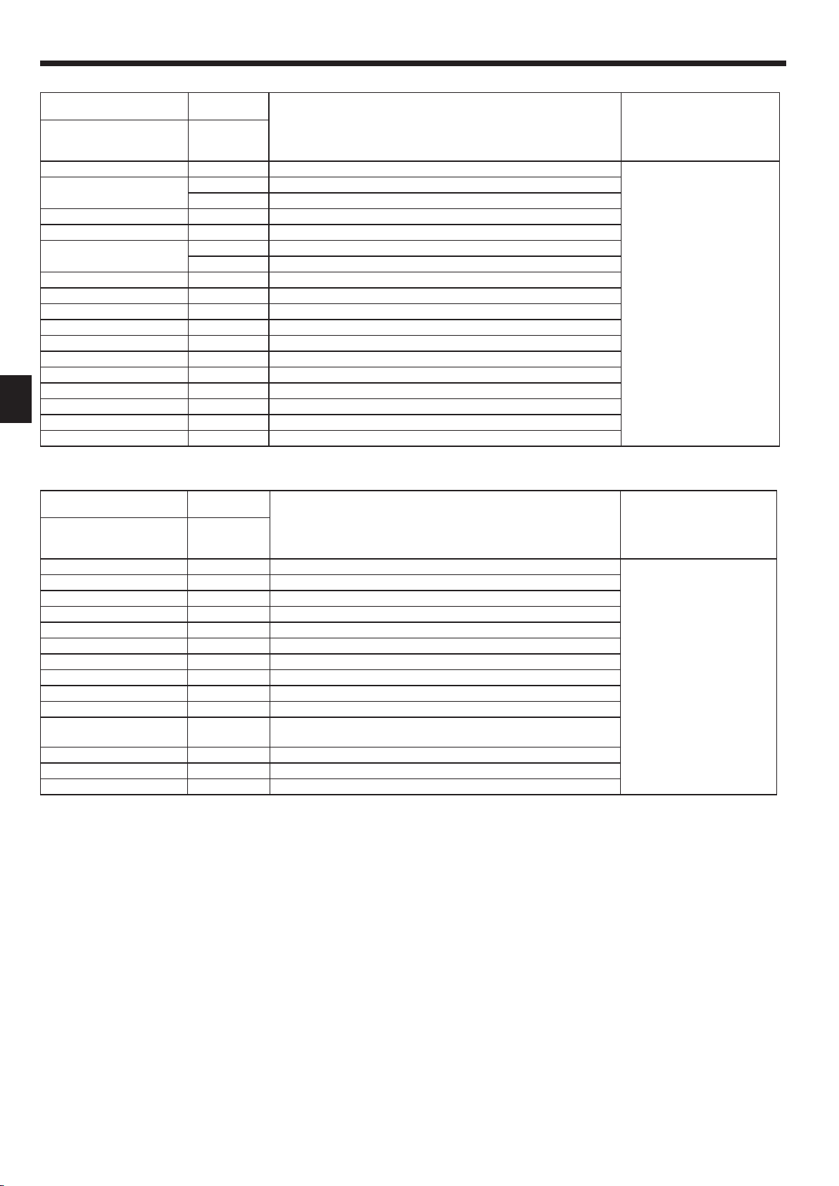
[Output pattern A] Errors detected by indoor unit
Wireless remote controller
Beeper sounds/OPERATION
INDICATOR lamp blinks
(Number of times)
1 P1 Intake sensor error
2
3 E6, E7 Indoor/outdoor unit communication error
4 P4 Drain sensor error/Float switch connector open
5
6 P6 Freezing/Overheating protection operation
7 EE Communication error between indoor and outdoor units
8 P8 Pipe temperature error
9 E4 Remote controller signal receiving error
10 — —
11 Pb Indoor unit fan motor error
12 Fb Indoor unit control system error (memory error, etc.)
14 PL Refrigerant circuit abnormal
No sound E0, E3 Remote controller transmission error
No sound E1, E2 Remote controller control board error
No sound – – – – No corresponding
Wired remote
controller
Check code
P2 Pipe (TH2) sensor error
P9 Pipe (TH5) sensor error
P5 Drain pump error
PA Forced compressor error
Symptom Remark
[Output pattern B] Errors detected by unit other than indoor unit (outdoor unit, etc.)
Wireless remote controller
Beeper sounds/OPERATION
INDICATOR lamp blinks
(Number of times)
1 E9 Indoor/outdoor unit communication error (Transmitting error) (Outdoor unit)
2 UP Compressor overcurrent interruption
3 U3, U4 Open/short of outdoor unit thermistors
4 UF Compressor overcurrent interruption (When compressor locked)
5 U2 Abnormal high discharging temperature/49C worked/insufcient refrigerant
6 U1, Ud Abnormal high pressure (63H worked)/Overheating protection operation
7 U5 Abnormal temperature of heat sink
8 U8 Outdoor unit fan protection stop
9 U6 Compressor overcurrent interruption/Abnormal of power module
10 U7 Abnormality of super heat due to low discharge temperature
11 U9, UH
12 — —
13 — —
14 Others Other errors (Refer to the technical manual for the outdoor unit.)
*1 If the beeper does not sound again after the initial 2 beeps to conrm the self-check start signal was received and the OPERATION INDICATOR lamp does not come on,
there are no error records.
*2 If the beeper sounds 3 times continuously “beep, beep, beep (0.4 + 0.4 + 0.4 sec.)” after the initial 2 beeps to conrm the self-check start signal was received, the specied
refrigerant address is incorrect.
• On wireless remote controller
The continuous buzzer sounds from receiving section of indoor unit.
Blink of operation lamp
• On wired remote controller
Check code displayed in the LCD.
Wired remote
controller
Symptom Remark
Check code
For details, check the LED
display of the outdoor controller
board.
Abnormality such as overvoltage or voltage shortage and abnormal synchronous signal to main circuit/Current sensor error
16
Page 17
7. Test run
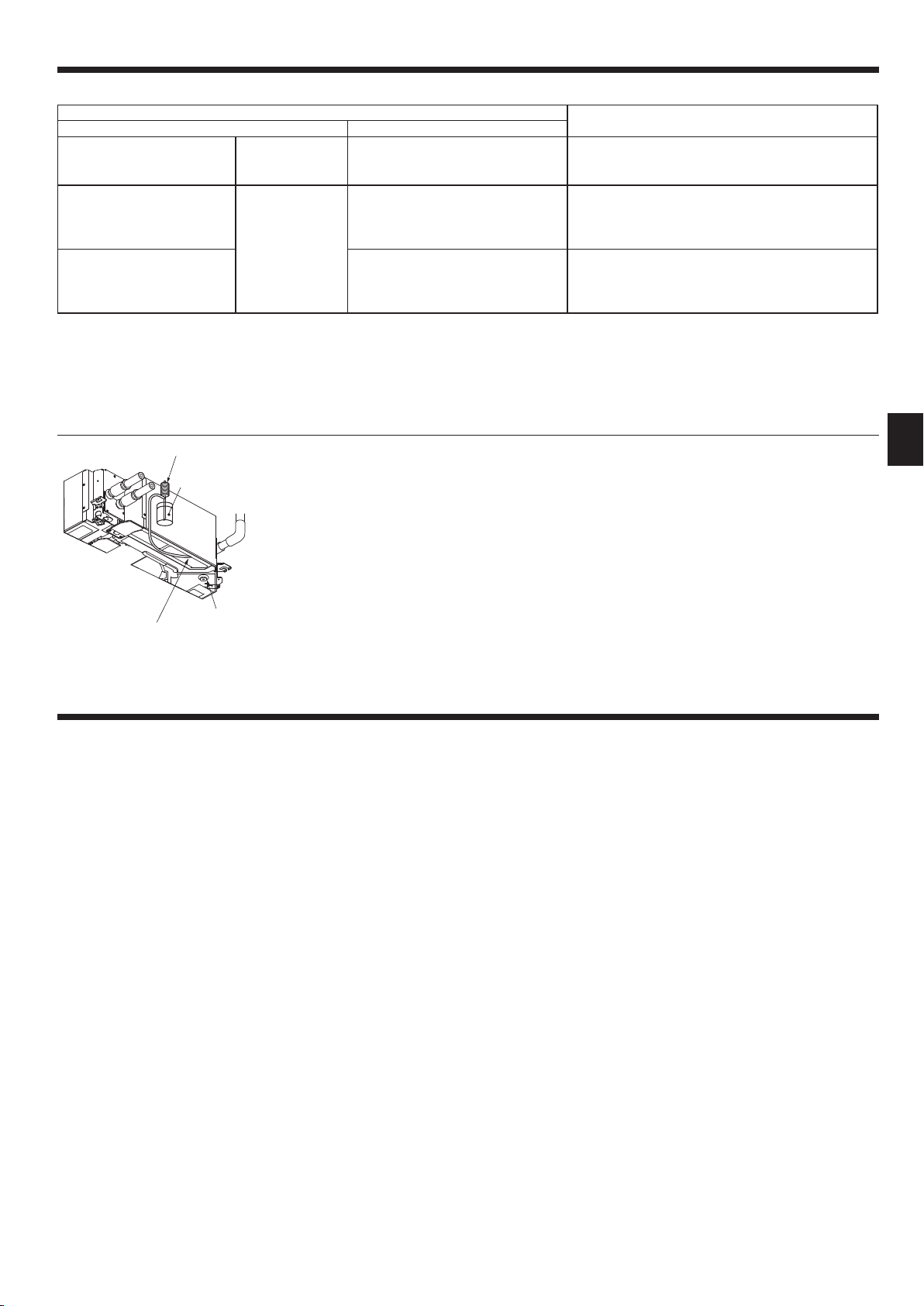
• If the unit cannot be operated properly after test run, refer to the following table to nd the cause.
Symptom
Wired remote controller LED 1, 2 (PCB in outdoor unit)
PLEASE WAIT
PLEASE WAIT
Display messages do not appear
even when operation switch is
turned ON (operation lamp does
not light up).
On the wireless remote controller with condition above, following phenomena take place.
• No signals from the remote controller are accepted.
• Operation lamp is blinking.
• The buzzer makes a short ping sound.
Note:
Operation is not possible for about 30 seconds after cancellation of function selection. (Correct operation)
For description of each LED (LED 1, 2, 3) provided on the indoor controller, refer to page 15.
Error code
→
For about 3 minutes
after power-on
Subsequent to
about 3 minutes
after power-on
After LED 1, 2 are lighted, LED 2 is turned
off, then only LED 1 is lighted. (Correct
operation)
Only LED 1 is lighted.
Only LED 1 is lighted.
twice, LED 2 blinks once.
LED 1, 2 blink.
→
LED 1 blinks
→
• For about 3 minutes after power-on, operation of the remote
controller is not possible due to system start-up. (Correct
operation)
• Connector for the outdoor unit’s protection device is not con-
nected.
Reverse or open phase wiring for the outdoor unit’s power
terminal block (L1, L2, L3)
• Incorrect wiring between indoor and outdoor units (incorrect
polarity of S1, S2, S3)
• Remote controller wire short
Cause
A
B
C
D
Fig. 7-5
8. System control
Refer to the outdoor unit installation manual.
A Water supply pump
B Water (about 1000 cc)
C Drain plug
D Pour water through outlet
• Be careful not to spray water into
the drain pump mechanism.
7.4. Check of drainage (Fig. 7-5)
• Ensure that the water is being properly drained out and that no water is leaking
from joints.
When electric work is completed.
• Pour water during cooling operation of test run (refer to 7.2.) and check.
When electric work is not completed.
• Pour water during emergency operation and check.
* Drain pan and fan are activated simultaneously when single phase 220-240 V is
turned on to S1 and S2 on terminal block after the connector (SWE) on controller
board in the electrical box is set to ON.
Be sure to turn it back to the former state after work.
17
Page 18

9. Installing the grille
1 2
3 4
When equipped with the wireless remote controller
5 6 7 8
Fig. 9-1
+5
0
A=17
B
C
A
D
Fig. 9-2
A
C
B
E
2
D
Fig. 9-3
G
H
G
F
F
1
Fig. 9-4
4-directional 3-directional
1 pattern: initial setting
Blowout direction
patterns
2-directional
6 patterns:
2 air outlet fully closed
Blowout direction
patterns
4 patterns:
one air outlet fully closed
9.1. Checking the contents (Fig. 9-1)
• This kit contains this manual and the following parts.
Accessory name Q’ty Remarks
1
Grille
2
Installation gauge
3
Screw (4 × 16)
4
i-see Sensor corner panel
5
Wireless remote controller
6
Remote controller holder 1
7
LR6 AA batteries 2
8
3.5 × 16 tapping screws 2
1
950 × 950 (mm)
1
(Divided into 4 parts)
1
For PLP-6EAE, PLP-6EALE, PLP-6EALME
1
For PLP-6EAE, PLP-6EALE, PLP-6EALME
1
For PLP-6EALM, PLP-6EALME
Included when equipped with the wireless remote controller.
Included when equipped with the wireless remote controller.
Included when equipped with the wireless remote controller.
9.2. Preparing to attach the grille (Fig. 9-2)
• With the gauge 2 supplied with this kit, adjust and check the positioning of the main
unit relative to the ceiling surface. If the main unit is not properly positioned relative
to the ceiling surface, it may allow air leaks or cause condensation to collect.
• Make sure that the opening in the ceiling is within the following tolerances:
860 × 860 - 910 × 910
• Make sure that A is performed within 17 - 22 mm. Damage could result by failing to
adhere to this range.
A Main unit
B Ceiling surface
C Installation gauge 2 (inserted into the main unit)
D Ceiling opening dimensions
9.2.1. Removing the intake grille (Fig. 9-3)
• Slide the levers in the direction indicated by the arrows 1 to open the intake grille.
• Unlatch the hook that secures the grille.
* Do not unlatch the hook for the intake grille.
• With the intake grille in the “open” position, remove the hinge of the intake grille
from the grille as indicated by the arrows 2.
2
B
9.2.2. Removing the corner panel (Fig. 9-4)
• Loose the 4 screws on the corner. Slide the corner panel in the direction of the arrow
1 in the gure and remove the corner panel.
[Fig. 9-3] [Fig. 9-4]
A Intake grille
B Grille 1
C Intake grille levers
D Grille hook
E Hole for the grille’s hook
F Corner panel
G Screw
H Detail
9.3. Selection of air outlets
For this grille the discharge direction is available in 11 patterns. Also, by setting the
remote controller to the appropriate settings, you can adjust the air-ow and speed.
Select the required settings from the Table 1 according to the location in which you
want to install the unit. (More than two directions must be selected.)
1) Decide on the discharge direction pattern.
2) Be sure to set the remote controller to the appropriate settings according to the
number of air outlets and the height of the ceiling on which the main unit will be
installed.
(Refer to page 13.)
Note:
• When changing the number of directions, you need an air outlet shutter plate,
which is optional part.
• Do not select 2 directions in a hot and humid environment. (Dew formation
or dew drop may result.)
18
Table 1
Fig. 9-5
9.4. Installing the grille
9.4.1. Preparations (Fig. 9-5)
<Hook is in the lowered position><Hook is in the raised position>
Make sure to ip 2 hooks on the grille up.
Page 19
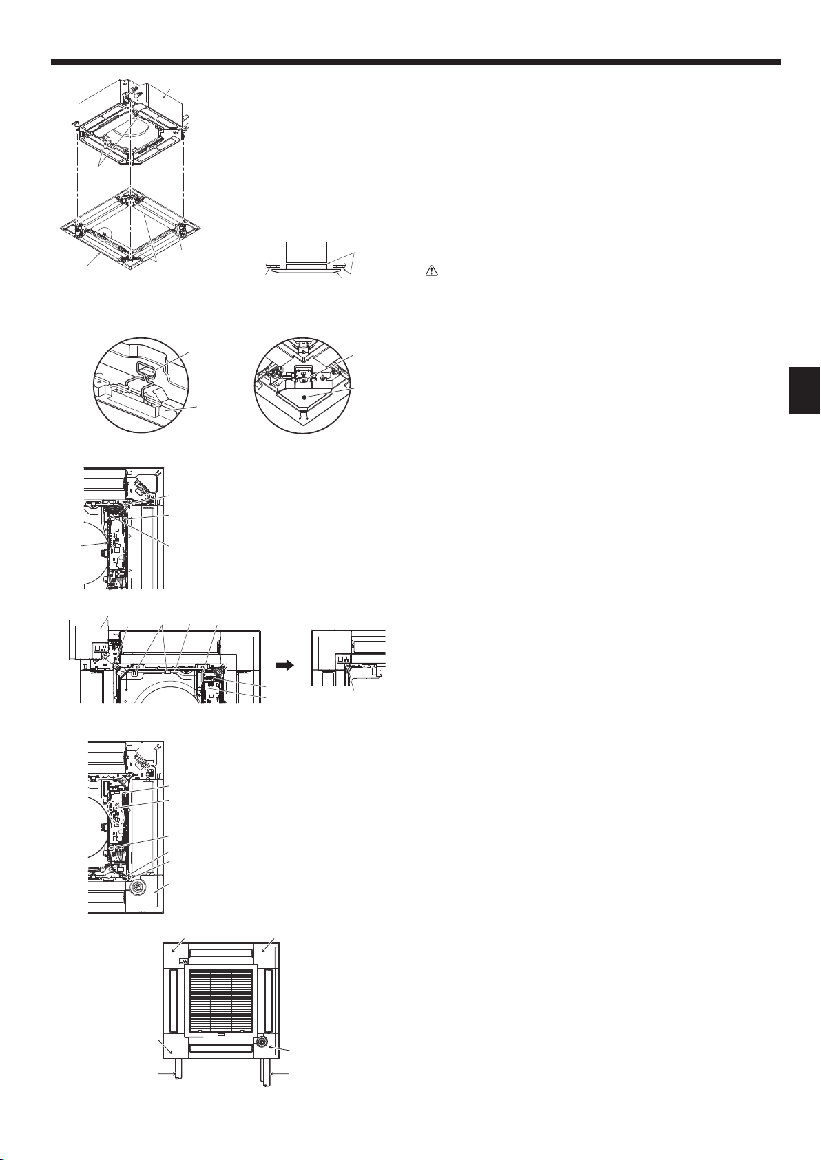
9. Installing the grille
A
B
C
E
D
< The grille temporary installed >
B
A
F
C
D
C
D
A
D
C
B
A Main unit
B Corner of drain pipe
C Claw on the main unit
D Grille 1
E Hole on the grille
F Hook for temporary installation
G Screw with captive washer
H Ceiling surface
J No gap
K Adjust the nut of main unit using a wrench,
etc.
A
H
J
D
Fig. 9-6
G
K
Fig. 9-7
A Clamp of the main unit
B Electrical box
C Lead wires of the grille
D CNV connector on the controller board
Fig. 9-8
E
9.4.2. Temporary installation of the grille (Fig. 9-6)
• Join the corner of drain pipe on the main unit with the corner with hole on the grille
and put them together temporarily by hanging the hook of the grille to the claw of
the main unit.
9.4.3. Fixing the grille
• By tightening the pre-installed screws, x the grille onto the main unit. (Fig. 9-6)
Note:
Make sure there is no gap between the main unit and the grille or between the
grille and the ceiling surface. (Fig. 9-6)
If there is a gap between the grille and the ceiling:
With the grille attached, slightly adjust the installation height of the main unit and
clear the gap.
Caution:
• When tightening the screw, make sure that the tightening torque is 2.8 N•m
to 3.6 N•m. Never use an impact screw driver.
• After tightening the screw, conrm that the two grille hooks (Fig. 9-7) are
latched onto the hooks on the main unit.
9.4.4. Wire connection (Fig. 9-8)
• Loose the 2 screws xing the electrical box cover on the main unit, and slide the
cover to open.
• Route the lead wire from side of the electrical box.
• Make sure to connect a connector for vane motor (white, 20 poles) to CNV con-
nector (white) on the controller board of the main unit.
• Lead wires that lead off the grille must be held together without slack using a clamp
into the electrical box.
9.4.5. Installing signal receiver (Fig. 9-9)
• Route the lead wire (white, 9 poles) for signal receiver corner panel from the side
of the electrical box on the main unit.
• Make sure to connect to CN90 (white) on the controller board.
• Make sure that the lead wire of the signal receiver corner panel is passed through
the claw of bellmouth.
• The remaining lead wire must be held together without slack using a clamp into
the electrical box.
• Put the cover back on the electrical box with 2 screws.
Note:
Make sure wires are not caught in the electrical box cover.
Install the signal receiver corner panel to the panel and x with the screw.
The signal receiver corner panel can not be installed on the drain pipe side for the
main unit. (Refer to Fig. 9-11)
Prohibited installation
position
Drain pipe
B
A
C
E
F
G
Position 1
F
G
H
Fig. 9-9
A CN4Z on the controller board
B CN5Y on the controller board
C Lead wire of i-see Sensor corner panel
D Clamp
E Hole of grille (Pass the lead wire.)
F Screw 3
G i-see Sensor corner panel 4
Fig. 9-10
Position 2
Position 3
Refrigerant pipe
A Signal receiver corner panel
B Hole of grille (Pass the lead wire.)
C Claw of bell mouth
D Wire
E Clamp
F Cable band (Secure the lead wire.)
G CN90 on controller board
H Screw
9.4.6. Installation of i-see Sensor corner panel (Fig. 9-10)
• Route the lead wire from the side of electrical box.
• Route the lead wire connector (white, 4 poles and white, 5 poles) of the i-see Sensor
corner panel 4 from the side of the electrical box on the main unit and connect to
the connector CN4Z and CN5Y on the controller board.
• The remaining lead wire of i-see Sensor corner panel must be held together without
slack using the clamp into the electrical box.
• Put the cover back on the electrical box with 2 screws.
Note:
Make sure wires are not caught in the electrical box cover.
• The i-see Sensor corner panel should be xed onto the grille 1 with screw 3.
* If the position of the i-see Sensor was changed from default position (position 3)
to the other position, change the function settings. (Refer to page 13 and Fig. 9-11)
• The i-see Sensor corner panel can not installed on the drain pipe side for the main
unit. (Refer to Fig. 9-11)
Position 1: Default signal receiver position (Air outlet identication marks □/□□□□)
Position 2: (Air outlet identication marks □/□□)
Position 3: Default i-see Sensor position (Air outlet identication marks □□/□□□)
Fig. 9-11
19
Page 20
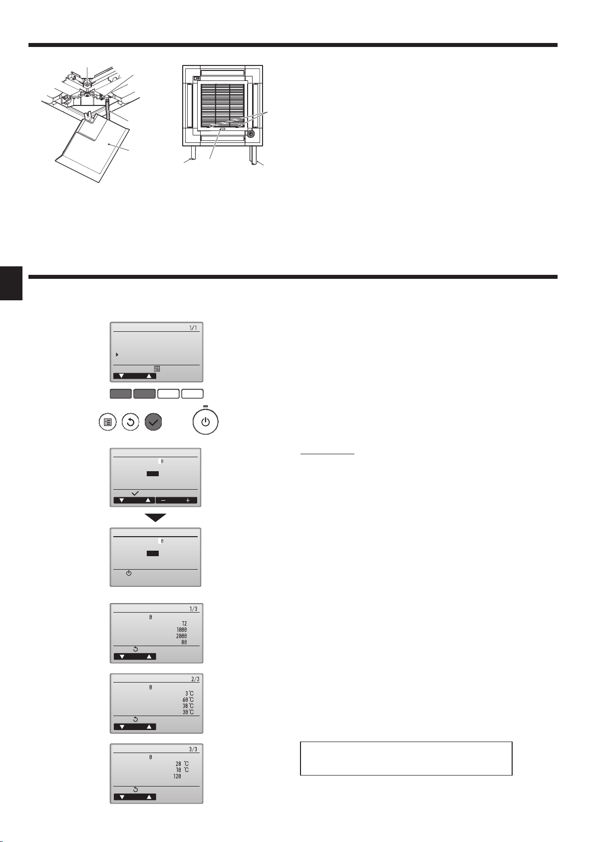
9. Installing the grille
A
D
9.5. Installing the intake grille (Fig. 9-12)
Note:
When reinstalling the corner panels (each with a safety strap attached), connect the other end of each safety strap to the grille as shown in the illustration.
* If the corner panels are not attached surely, they may fall off while the main unit is
H
C
operating.
• Perform the procedure that is described in “9.2. Preparing to attach the grille” in
reverse order to install the intake grille and the corner panel.
• The direction of the intake grille can be changed according to the wishes of the
customer.
B
G
F
E
A Screw (4 × 16)
B Corner panel
C Safety strap
D Hook
Fig. 9-12
E Refrigerant pipe
F Drain pipe
G Company logo
* Installation in any position is possible.
H Initial position of the levers on the intake grille
* Although the clips can be installed in any of 4 positions, the conguration shown
here is recommended. (It is not necessary to remove the intake grille when main-
tenance is performed on the electrical box of the main unit.)
10. Easy maintenance function
Maintenance data, such as the indoor/outdoor unit’s heat exchanger temperature and compressor operation current can be displayed with “Smooth maintenance”.
* This cannot be executed during test operation.
* Depending on the combination with the outdoor unit, this may not be supported by some models.
1
Error history
Refrigerant volume check
Refrigerant leak check
Smooth maintenance
Request code
Service menu:
Cursor
Check menu
• Select “Service” from the Main menu, and press the [SELECT] button.
• Select “Check” with the [F1] or [F2] button, and press the [SELECT] button.
• Select “Smooth maintenance” with the [F1] or [F2] button, and press the [SELECT]
button.
F1 F2 F3 F4
2
3
Smooth maintenance
Ref.address
Stable mode
Cool / Heat/ Normal
Begin:
Cursor
Smooth maintenance
Ref.address
Stable mode
Cool / Heat/ Normal
Stabilization→Collecting
Exit:
Smooth maintenance
Ref. address
COMP. current
COMP. run time
COMP. On / Off
COMP. frequency
Return:
Page
Smooth maintenance
Ref.address
Sub cool
OU TH4 temp.
OU TH6 temp.
OU TH7 temp.
Return:
Page
Cool
Cool
Address
A
Hr
times
Hz
Select each item.
• Select the item to be changed with the [F1] or [F2] button.
• Select the required setting with the [F3] or [F4] button.
“Ref. address” setting ………. “0” - “15”
“Stable mode” setting……….. “Cool” / “Heat” / “Normal”
• Press the [SELECT] button, xed operation will start.
* Stable mode will take approx. 20 minutes.
The operation data will appear.
The Compressor-Accumulated operating (COMP. run) time is 10-hour unit, and the
Compressor-Number of operation times (COMP. On/Off) is a 100-time unit (fractions
discarded)
20
Smooth maintenance
Ref.address
IU air temp.
IU HEX temp.
IU filter time
Return:
Page
Cool
Navigating through the screens
• To go back to the Main menu ....................[MENU] button
• To return to the previous screen .......... [RETURN] button
Hr
Page 21
Содержание
1. Мерыпредосторожности..................................................................... 211
2. Местоустановки ..................................................................................212
3. Установкавнутреннегоприбора .........................................................212
4. Прокладкатрубхладагента ................................................................ 215
5. Дренажныетрубы ................................................................................ 216
Примечание:
Вэтомруководствепоиспользованиюаппаратафраза“проводнойпультдистанционногоуправления”относитсякпультудистанционногоуправленияPAR-33MAA.
Сведенияодругихпультахдистанционногоуправленияприводятсявруководствепоустановкеилируководствепоначальнымнастройкам,находящемсяв
этихкоробках.
6. Электрическиеработы ........................................................................217
7. Выполнениеиспытания.......................................................................223
8. Управлениесистемой .........................................................................226
9. Установкавентиляционнойрешетки ..................................................227
10.Функцияпростоготехобслуживания ..................................................229
1. Мерыпредосторожности
►Передустановкойданногоприбора,пожалуйстаобязательнопрочитайтевсе“Мерыпредосторожности”.
Вразделе“Мерыпредосторожности”изложеныоченьважныесведения,касающиесятехникибезопасности.Обязательноследуйтеэтиминструкциям.
►
►Передподключениемоборудованияксистемепитанияинформируйтеобэтомвашуэнергоснабжающуюорганизациюилиполучитееесогласие.
ЗНАЧЕНИЯСИМВОЛОВ,ОТОБРАЖАЕМЫХНАУСТРОЙСТВЕ
ДанныйсимволприменяетсятолькодляхладагентаR32.Типхладагентауказываетсянабиркенаружногоприбора.
ПРЕДУПРЕЖДЕНИЕ
(опасностьвозгорания)
ВнимательнопрочтитеРУКОВОДСТВОПОЭКСПЛУАТАЦИИпередначаломэксплуатации.
ОбслуживающийперсоналобязанвнимательнопрочитатьРУКОВОДСТВОПОЭКСПЛУАТАЦИИиРУКОВОДСТВОПОУСТАНОВКЕпередначаломработ.
ДополнительнуюинформациюможнонайтивРУКОВОДСТВЕПОЭКСПЛУАТАЦИИ,РУКОВОДСТВЕПОУСТАНОВКЕианалогичныхдокументах.
Символика,используемаявтексте
Предупреждение:
Описываетмерыпредосторожности,которыеследуетвыполнять,чтобы
избежатьтравмыилигибелипользователя.
Осторожно:
Описываетмерыпредосторожности,которыеследуетвыполнять,чтобы
неповредитьприбор.
Еслитипхладагента—R32,товданномустройствеиспользуетсяогнеопасныйхладагент.
Вслучаеутечкихладагентаиегоконтактасогнемилиисточникомтеплаобразуетсявредныйгазивозникнетопасностьвозгорания.
Символы,указанныенаиллюстрациях
:Указывает,чтоэтачастьдолжнабытьзаземлена.
:Строговоспрещается.
После окончания установочныхработпроинструктируйте пользователя
относительноправил эксплуатации и обслуживания аппарата,атакже
ознакомьтесразделом“Мерыпредосторожности”всоответствиисинформацией,приведеннойвРуководствепоиспользованиюаппарата,ивыполнитетестовыйпрогонаппаратадлятого,чтобыубедиться,чтоонработает
нормально.Обязательнопередайтепользователюнахранениеэкземпляры
РуководствапоустановкеиРуководствапоэксплуатации.ЭтиРуководства
должныбытьпереданыипоследующимпользователямданногоприбора.
Предупреждение:
• Внимательнопрочтитетекстнаэтикеткахглавногоприбора.
• Дляустановки,перемещенияиремонтаустройстваобратитеськдилеру
илиуполномоченномутехническомуспециалисту.
• Запрещаетсясамостоятельныйремонтилиперемещениеприбора.
• Неизменяйтеустройство.
• Для установкии перемещенияследуйте инструкциям,приведенным в
Руководствепоустановке,ииспользуйтеинструментыитрубныекомпоненты,специальнопредназначенныедляиспользованиясхладагентом,
указанныевруководствепоустановкенаружногоприбора.
• Прибордолженбытьустановленсогласноинструкциям,чтобысвестик
минимумурискповрежденияотземлетрясений,тайфуновилисильных
порывов ветра.Неправильноустановленный прибор может упасть и
причинитьповреждениеилинанеститравму.
Прибордолженбытьустановленнаконструкции,способнойвыдержатьеговес.
•
•
Устройствонеобходимосодержатьвхорошопроветриваемомпомещении,размерыкоторогосоответствуютразмерампомещения,указаннымдляэксплуатации.
•
Есликондиционерустановлен в небольшомили закрытомпомещении,
необходимопринятьмерыдляпредотвращенияконцентрациихладагента
впомещениисвышебезопасныхпределовв случаеутечкихладагента.В
случаеутечкихладагентаипревышениидопустимойегоконцентрациииз-за
нехваткикислородавпомещенииможетпроизойтинесчастныйслучай.
• Недопускайтеразмещениягазоиспользующихустройств,электрообогре-
вателейидругихочаговвозгорания(источниковвозгорания)возлемест
осуществленияустановки,ремонтаидругихработскондиционером.
Приконтактехладагентасогнемобразуетсятоксичныйгаз.
Есливовремя работыприборапроизошла утечкахладагента,проветрите
•
помещение.Приконтактехладагентаспламенемобразуютсяядовитыегазы.
• Всеэлектроработыдолжнывыполнятьсяквалифицированнымтехни-
ческимспециалистомвсоответствиисместнымиправиламииинструкциями,приведеннымивданномРуководстве.
Используйтедляпроводкиуказанныекабели.Убедитесь,чтокабелинадежно
•
соединены,а оконечныесоединения ненатянуты.Никогданесоединяйте
кабеливнахлест(еслииноенеуказановприлагаемойдокументации).Несоблюдениеэтихинструкцийможетпривестикперегревуиливозгоранию.
•
Приустановке,перемещенииилиобслуживаниикондиционерадлязаправки
трубопроводовхладагентаиспользуйтетолькототхладагент,которыйуказан
нанаружномустройстве.Несмешивайтеегонискакимдругимхладагентом
инедопускайтеналичиявоздухавтрубопроводах.
Наличиевоздухавтрубопроводахможетвызыватьскачкидавления,в
результатекоторыхможетпроизойтивзрывилидругиеповреждения.
Использованиелюбогохладагента,отличногоотуказанногодляэтойси-
стемы,вызоветмеханическоеповреждение,сбоивработесистемы,или
выходустройстваизстроя.Внаихудшемслучае,этоможетпослужить
серьезнойпреградойкобеспечениюбезопаснойработыэтогоизделия.
• Установкунеобходимо выполнятьвсоответствии сдействующими
правиламиэлектробезопасности.
• Данныйприборнепредназначендляиспользованиялюдьми(включая
детей)сограниченнымифизическими,сенсорнымиилипсихическими
возможностями.Принедостаткеопытаизнанийразрешаетсяпользоватьсяданнымприборомтолькоподнаблюдениемлица,ответственногоза
безопасность,илипослеинструктажапоиспользованиюприбора.
• Следуетследитьзадетьми,чтобыонинеигралисустройством.
•
Крышкараспределительногощитадолжнабытьнадежноприсоединенакприбору.
• Поврежденный кабельиз комплектапоставки долженбыть замененв
целяхбезопасностипроизводителем,сервиснымагентомилилицами,
обладающиминеобходимойквалификацией.
• Используйте толькотедополнительные принадлежности,накоторые
имеетсяразрешениеотMitsubishiElectric;дляихустановкиобратитесь
кдилеруилиуполномоченномутехническомуспециалисту.
•
Поокончанииустановкиубедитесьвотсутствииутечкихладагента.Еслихладагентпроникнетвпомещениеипроизойдетконтактегоспламенемобогревателя
илипереносногопищевогонагревателя,образуютсяядовитыхгазов.
• Неиспользуйтесредствадляускоренияразмораживанияиочистки,если
онинерекомендованыпроизводителем.
• Устройстводолжнохранитьсявпомещениибезнепрерывноработающих
источниковвоспламенения(например,открытогопламени,работающего
газовогоприбораилиэлектрическогообогревателя).
• Неделайтеотверстийпутемсверленияилипрожигания.
• Имейтеввиду,чтохладагентымогутнеиметьзапаха.
• Недопускайтефизическогоповреждениятрубопроводов.
• Установкатрубопроводовдолжнабытьсведенакминимуму.
• Соблюдайтенациональныенормативы,касающиесягаза.
• Недопускайтезасоренияпредусмотренныхвентиляционныхотверстий.
•
Неиспользуйтелегкоплавкийприпойдляпайкитрубопроводовхладагента.
• Вовремяпайкиобязательнопроветривайтепомещение.
Убедитесь, чтовокруготсутствуютопасныеиливоспламеняющиеся
материалы.
Приработевзакрытом,небольшомилидругоманалогичномпомещении
передвыполнениемработубедитесьвотсутствииутечкихладагента.
При утечке инакоплениихладагента он можетзагореться, или может
выделятьсятоксичныйгаз.
211
Page 22

1. Мерыпредосторожности
1.1. Передустановкой(Окружающаясреда)
Осторожно:
•
Неиспользуйтеприборвнестандартнойокружающейсреде.Установкакондиционеравместах,подверженныхвоздействиюпара,летучихмасел(включая
машинноемасло)илисернистыхиспарений,местахсповышеннойконцентрациейсоли(таких,какберегморя),можетпривестикзначительномуснижению
эффективностиработыприбораилиповреждениюеговнутреннихчастей.
•
Неустанавливайтеприборвместах, гдевозможнаутечка,возникновение,
притокилинакоплениегорючихгазов.Еслигорючийгазбудетнакапливаться
вокругприбора,этоможетпривестиквозникновениюпожараиливзрыву.
•
Недержитепищевыепродукты,растения,домашнихживотныхвклетках,
произведенияискусстваиточныеинструментывпрямомпотокевоздухаот
внутреннегоприбораилислишкомблизкокнему,посколькуэтипредметы
могутбытьповрежденыперепадамитемпературыиликапающейводой.
1.2. Передустановкойилиперемещением
Осторожно:
• Будьте чрезвычайноосторожныпритранспортировкеприборов.Прибордолжныпереноситьдваилиболеечеловека,посколькуонвеситне
менее20кг.Неподнимайтеприборзаупаковочныеленты.Используйте
защитныеперчатки,посколькуможноповредитьрукиребристымидеталямиилидругимичастямиприбора.
• Утилизируйтеупаковочныематериалынадлежащимобразом.Упаковочныематериалы,такие,какгвоздиидругиеметаллическиеилидеревянныечасти,могутпоранитьилипричинитьдругиетравмы.
• Дляпредотвращенияконденсациинеобходимообеспечитьтеплоизоляциютрубыхладагента.Еслитрубахладагентанеизолированадолжным
образом,приработеприборабудетобразовыватьсяконденсат.
•
Обернитетрубытеплоизоляционнымматериаломдляпредотвращенияконденсации.Еслидренажнаятрубаустановленанеправильно,этоможетвызвать
протечкуводыииспортитьпотолок,пол,мебельилидругоеимущество.
1.3. Передэлектрическимиработами
Осторожно:
• Обязательно установите автоматическиевыключатели.В противном
случаевозможнопоражениеэлектрическимтоком.
• Используйтедляэлектропроводкистандартныекабели,рассчитанные
насоответствующуюмощность.Впротивномслучаеможетпроизойти
короткоезамыкание,перегревилипожар.
• Примонтажекабелейпитаниянеприкладывайтерастягивающихусилий.
• Приуровневлажностивпомещениивыше80%илизакупоркедренажной
трубыиз внутреннегоприбора можеткапать вода.Не устанавливайте
внутреннийприборвместах,гдетакиекаплимогутвызватькакое-либо
повреждение.
•
Примонтажеприборавбольницеилицентресвязипримитевовнимание
шумовоеиэлектронноевоздействие.Работатакихустройств,какинверторы,бытовыеприборы,высокочастотноемедицинскоеоборудованиеи
оборудованиерадиосвязиможетвызватьсбоивработекондиционераили
егополомку.Кондиционертакжеможетповлиятьнаработумедицинского
оборудованияимедицинскоеобслуживание,работукоммуникационного
оборудования,вызываяискажениеизображениянадисплее.
• Немойтекондиционерводой.Этоможетпривестикпоражениюэлектрическимтоком.
• Затягивайтевсехомутынамуфтахвсоответствиисоспецификациями,
используяключсрегулируемымусилием.Слишкомсильнозатянутый
хомутмуфтыпопрошествиинекотороговремениможетсломаться.
•
Если приборработает длительное времяивышепотолка присутствует
воздухвысокойтемпературы/высокойвлажности(вышеточкиросы26°С),
вовнутреннемприбореилина потолочных материалахможетвозникать
конденсацияросы.Приэксплуатацииприборовв такихусловиях,навсю
поверхностьприбораи потолочныхматериалов следуетдобавлятьизоляционныйматериал(10–20мм),чтобыпредотвратитьконденсациюросы.
• Обязательно заземлите прибор.Отсутствиенадлежащегозаземления
можетпривестикпоражениюэлектрическимтоком.
• Используйтеавтоматическиевыключатели(прерывательутечкитокана
землю,разъединитель(плавкийпредохранитель+B)ипредохранитель
корпуса)суказанным предельнымтоком. Еслипредельныйток автоматическоговыключателябольше,чемнеобходимо,можетпроизойти
поломкаилипожар.
1.4. Передтестовымпрогоном
Осторожно:
• Включайтеглавныйвыключательпитаниянепозднее,чемза12часов
до началаэксплуатации.Запуск прибора сразу после включениявыключателяпитанияможетсерьезноповредитьвнутренниечасти.
• Передначаломэксплуатациипроверьте,чтовсепульты,щиткиидругие
защитныечастиправильноустановлены.Вращающиеся,нагретыеили
находящиесяподнапряжениемчастимогутнанеститравмы.
2. Местоустановки
Смотритеруководствопоустановкенаружногоприбора.
3. Установкавнутреннегоприбора
1 2
3 4
5 6
• Не включайтекондиционербез установленного воздушногофильтра.
Есливоздушный фильтрнеустановлен,вприбореможетнакопиться
пыль,чтоможетпривестикегополомке.
• Неприкасайтесьниккакимвыключателямвлажнымируками.Этоможет
привестикпоражениюэлектрическимтоком.
•
Неприкасайтеськтрубамсхладагентомголымирукамивовремяработыприбора.
• Послеостановкиприбораобязательноподождитепокрайнеймерепять
минутпередвыключениемглавноговыключателяпитания.Впротивном
случаевозможнапротечкаводыилиполомкаприбора.
3.1. Проверьтеналичиедополнительныхпринадлежностейквнутреннемуприбору(Fig.3-1)
Внутреннийприбордолженпоставлятьсявкомплектесоследующимидополнительнымипринадлежностями:
Названиеприспособления Количество
Установочныйшаблон(верхупаковки) 1
1
Прокладка(сизоляцией)
2
Прокладка(безизоляции)
Изоляциядлятруб(длясоединениятрубхладагента)
малогодиаметра
3
большогодиаметра
Лента(большая) 8
4
Лента(маленькая) 1
5
Соединительнаямуфтадлядренажа 1
6
Изоляция 1
7
Гайкараструбногостыка1/4F(M60) 1
8
4
4
1
1
7
212
8
Fig.3-1
Page 23
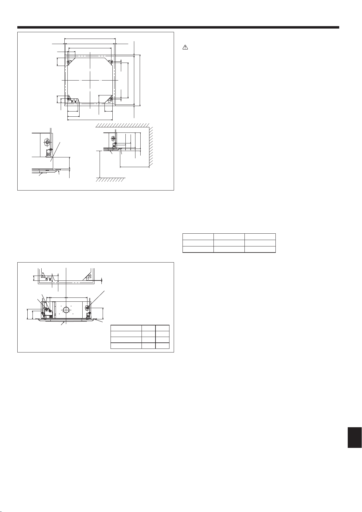
3. Установкавнутреннегоприбора
20 – 45
145
145
950 D
860 – 910 C
795 B
20 – 45
20 – 45
(20)
3.2.Расположениеотверстиявпотолкеинавесных
болтов(Fig.3-2)
Предупреждение:
Данноеустройстводолжно быть установленов помещениях, площадь
•
которыхбольшеуказаннойвруководствепоустановкенаружногоприбора.
Обратитеськруководствупоустановкенаружногоприбора.
• Установитевнутреннийблокнавысотеминимум2,5мнадуровнем
полаилиповерхности.
Общийдоступкприборамограничен.
• Ксоединению труб хладагентанеобходимо предусмотретьдоступ для
техническогообслуживания.
• Спомощьюустановочногошаблона(верхупаковки)икалибра(поставляетсяв
комплектедополнительныхпринадлежностейкрешетке)проделайтеотверстие
впотолкетакимобразом,чтобыглавныйприборможнобылоустановить,как
показанонадиаграмме.(Методиспользованияшаблонаикалибрауказан.)
* Прежде,чемиспользоватьшаблоникалибр,проверьтеихразмеры,по-
133
79,5
193
222
840 A
145
145
(20)
660 B
950 D
860 – 910 C
20 – 45
сколькуонименяютсяиз-заперепадовтемпературивлажности.
* Размерпотолочногоотверстияможнорегулироватьвпределах,указанных
G
E
135
0
+5
F
E
17
Мин.2500
Пол
*50 – 70
F
Мин.1500
*105
+5
A
* B
0
40
17
H
Fig.3-2
наFig.3-2,такимобразом,чтобыотцентроватьглавныйприборвпотолочномотверстии,обеспечиводинаковыезазорыповсемсоответствующим
противоположнымсторонам.
• ИспользуйтенавесныеболтыМ10(3/8").
* Навесныеболтыприобретаютсянаместе.
• Выполнитеустановку,убедившись,чтомеждупотолочнойпанельюирешеткой,
атакжемеждуглавнымприборомирешеткойнетзазора.
Внешняясторонаглавногоприбора
A
EРешетка
BШагболта FПотолок
CПотолочноеотверстие
DВнешниесторонырешетки
GМногофункциональныйокон-
ныйпереплет(опция)
HОбщеепространство
*
Заметьте,чтомеждупотолочнойпанельюприбораипотолочнойплитойит.д.
необходимооставитьрасстояниеот7ммиболее.
Приустановкеопционального многофункциональногооконногопереплета
*
добавьте135ммкрасстояниям,приведеннымнарисунке.
(мм)
Модели A B
M35-71 241 258
M100-140 281 298
*170
D
*140
3.3. Расположениетрубхладагента и дренажных
F
C
79,5
D
60 357271
E
C
6
A
*190
B
Модели
M35,50 76 76,5
M60 80,5 79,5
M71-140 79,5 79,5
(мм)
C D
трубдлявнутреннегоблока(Fig.3-3)
Цифры,помеченнаясимволом*нарисунке,представляютгабаритыосновного
приборазаисключениемгабаритов опциональногомногофункционального
оконногопереплета.
AДренажнаятруба
BПотолок
CРешетка
DТрубахладагента(жидкость)
EТрубахладагента(газ)
FОсновнойприбор
Приустановкеопционального многофункциональногооконногопереплета
*
добавьте135ммкрасстояниям,приведеннымнарисунке.
Fig.3-3
213
Page 24
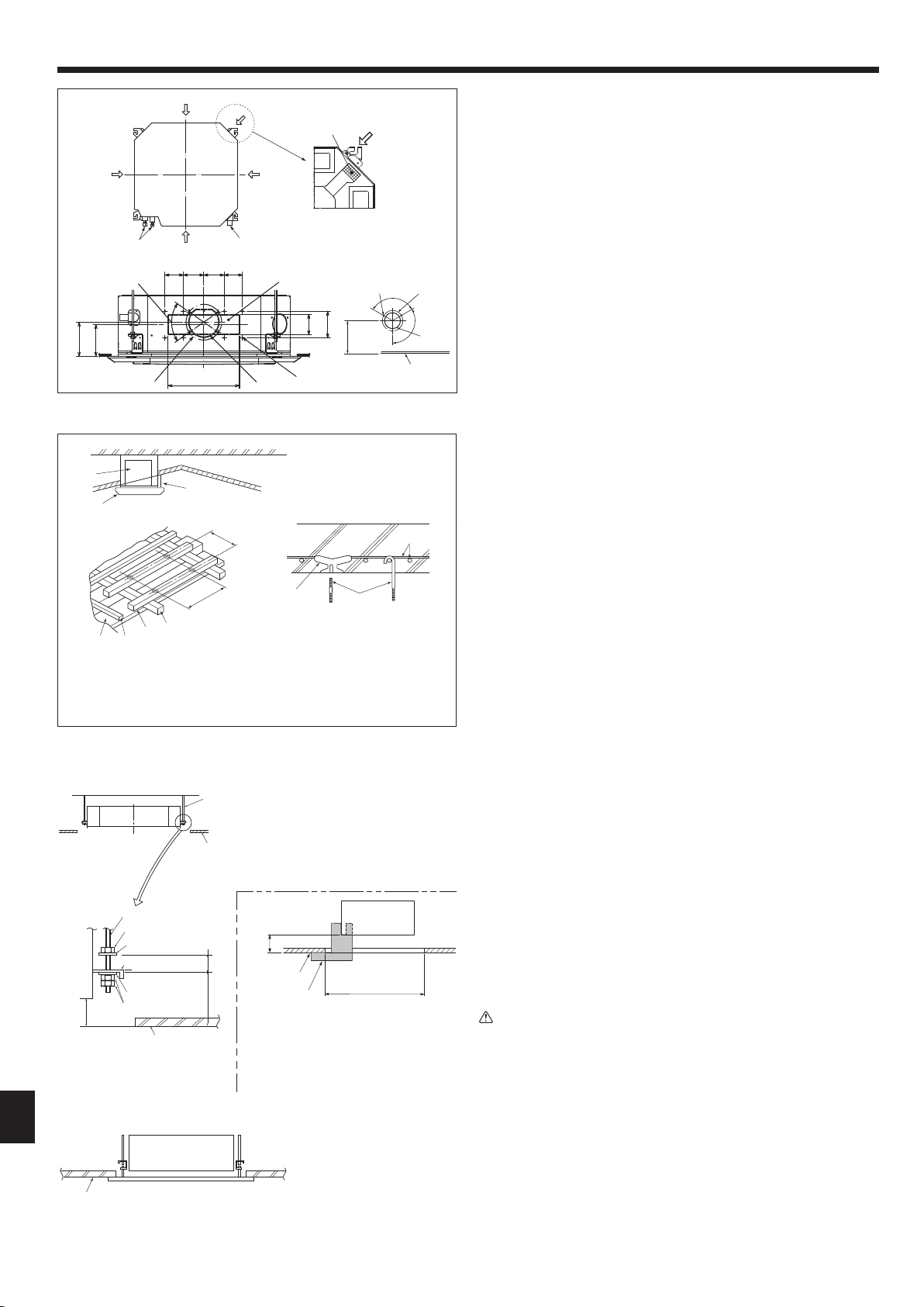
3. Установкавнутреннегоприбора
A
E
70°
B
A
90 100 100 90
A
F
*167
*155
I
A
C
B
1 2
G
D E
D Потолок
E Стропило
FБалка
G Балкакрыши
F
A
C
D
E
F
+5
0
C
G
17
B
Fig.3-6
A
B
C
350
795
A
C
P
A
O
D
A
100
130
*158
G
H
Fig.3-4
A Основнойблок
B Решетка
C Опора
660
H
H Используйтевставкисрейтин-
гом100-150кгкаждая(приобретаютсянаместе)
I НавесныеболтыМ10(3/8")
(приобретаютсянаместе)
J Стальнойстерженьдля
укрепления
Fig.3-5
A
Навеснойболт(приобретаютсянаместе)
BПотолок
CГайка
DПрокладка(сизоляцией)
EПлитадлянавешивания
B
FПрокладка(безизоляции)
GПроверьтеспомощью установочного
калибра
+5
Мин.30
)
240
(
105
0
A=17
B
C
A Главныйприбор
B Потолок
C Шаблон
D Габаритыпотолочного
отверстия
Fig.3-7
AГлавныйприбор
BПотолок
CУстановочныйшаблон
(верхупаковки)
Fig.3-8
J
I
D
3.4.
Отверстиедляответвлениявентиляционногоканалаи
входноеотверстиедлясвежеговоздуха(Fig.3-4)
F
K
L
120°
120°
M
N
J
Вовремяустановкипомеренеобходимостииспользуйтеотверстиявентиляционного
канала(вырезанные),расположенныевпозициях,показанныхнаFig.3-4.
• Такжеможнопроделатьвходноеотверстиедлясвежеговоздухадляопциональногомногофункциональногооконногопереплета.
Примечание:
•
Цифры,помеченные*нарисункепредставляютразмерыосновногоприбора,не
включающиеразмерыопциональногомногофункциональногооконногопереплета.
• Приустановкемногофункциональногооконногопереплетадобавьте135
ммкразмерам,обозначеннымнарисунке.
• Приустановкеответвленийвентиляционногоканалатщательнообернитеихизоляцией.Впротивномслучаевозможнообразованиеконденсацииикапаниеводы.
•
Вовремясозданиявходногоотверстиядлясвежеговоздуха,убедитесь,чтовы
удалилиизоляционныйматериалP,которыйналоженнавнутреннийприбор.
• Когданаружныйвоздухподаетсянепосредственночерезглавныйприбор,
объемприточноговоздухадолженбытьнебольше5%отобъемавоздуха
внутреннегоприбора.
• Дляподачинаружноговоздухатребуютсяканальныйвентиляторифильтр
длясборапылидлязащитыотзаборапылиидругихчастиц.
Дляполученияболееподробнойинформациисм.“Freshairintakevolume&
staticpressurecharacteristics”(Объемпритокасвежеговоздухаихарактеристикистатическогодавления)вСБОРНИКЕДАННЫХсерииР.
• Припоступлениинаружноговоздухавглавныйприборрабочийшумможет
бытьбольшегодиапазона.
AОтверстиедляответвлениявентиляцион-
ногоканала
BОсновнойблок
CВходноеотверстиедлясвежеговоздуха KШурупы-саморезы3-4×10
DДренажнаятруба LШаготверстияø125
EТрубахладагента MВырезноеотверстиеø100
FДиаграммаотверстиядляответвления NПотолок
вентиляционногоканала(видсобеихсторон)
G Шурупы-саморезы14-4×10
HВырезноеотверстиеø150 PИзоляция
IШаготверстияø175
JДиаграммавходногоотверстиядля
свежеговоздуха
OПодробныйрисунокдемонстрирующий
удалениеизоляционногоматериала
3.5. Подвеснаяконструкция(Обеспечьте
прочностьнаместеподвешивания)(Fig.3-5)
• Потолочныеконструкциимогутбытьразными,взавистмостиотконструкцииздания.
Следуетпроконсультироватьсясостроительнойиремонтнойорганизацией.
(1)Снятие потолочного покрытия: Потолокдолженбыть абсолютно горизонтальным
ипотолк (деревянныеплитыибалки)следуетукрепить,чтобы обеспечитьзащиту
потолкаотвибрации.
(2)Вырежьтеучастокпотолочнойплитыиснимитеего.
(3)Укрепитекраяпотолочнойплитыпоместамсрезаизакрепитееедополнительным
материаломпокраям.
(4)При установкеприбора напокатомпотолке,вставьтеопорумеждупотолкомире-
шеткойтак,чтобыприборбылустановленгоризонтально.
1
Деревянныеконструкции
• Вкачестве укрепленияиспользуйтеанкерныебалки(одноэтажные дома)илибалки
перекрытия(двухэтажныедома).
• Деревянные балкидляподвешивания кондиционера должны бытьпрочнымии их
боковыестороныдолжны бытьдлинойне менее6см, еслибалкиразделяются не
более,чем90см;ихбоковыестороныдолжныбытьдлинойнеменее9см,еслибалки
разделяютсярасстоянием180см.Размернавесныхболтовдолженбытьø10(3/8").
(Болтынепоставляютсявместесприбором.)
2
Железобетонныеконструкции
Закрепляйтенавесныеболты, используяуказанныйметод,илииспользуйтестальные
илидеревянныеподвесныекрепленияит.д.дляустановкинавесныхболтов.
3.6. Порядокподвешиванияприбора(Fig.3-6)
Подвешивайтеглавныйприбор,какуказанонадиаграмме.
Цифры,указанныевкруглых скобках, представляютрасстоянияв случае установки
опциональногомногофункциональногооконногопереплета.
1. Заранееустановитедеталинанавесныеболтывследующемпорядке:прокладки
(сизоляцией),прокладки(безизоляции)игайки(двойные).
•
A
Установитепрокладусизоляциейтакимобразом,чтобыизоляциябыланаправленавниз.
• Прииспользованииверхнихпрокладокдляподвешиванияглавногоприборанижние
прокладки(сизоляцией)игайки(двойные)устанавливаютсяпозднее.
2.
Поднимитеприборнатребуемуювысотудонавесныхболтов,чтобывставитьплиту
длянавешиванияприборамеждупрокладками,азатемнадежнозакрепитее.
3.
Еслинельзясовместитьглавныйприборсотверстиемдлянавешинаваниянапотолке,регулировкапроизводитсяспомощьющели,имеющейсянаплитедлянавешиванияприбора.
• Убедитесьвтом,чтооперацияАвыполняетсявпределах17-22мм.Несоблюдение
данногопределаможетврезультатепривестикповреждениям.(Fig.3-7)
Осторожно:
Используйтеверхнююполовинукоробкивкачествезащитногокожухадляпредотвращенияпопаданиепылиимусоравнутрьприборадоустановкидекоративной
крышкиилипринанесениипотолочныхматериалов.
3.7. Проверка расположения главногоприбораи
затягиваниенавесныхболтов(Fig.3-8)
•
Спомощьюкалибра,прикрепленногок решеткам,убедитесь,чтонизглавного приборасориентировандолжнымобразомпоотношениюкпотолочномуотверстию.Подтвердитеэто,в
противномслучаевозможнокапаниеконденсациивследствиепроникновениявоздухаит.д.
• Убедитесь,чтоглавныйприборустановленстрогопогоризонтали:используйтеуровень
иливиниловуютрубку,наполненнуюводой.
• Послепроверкирасположения главногоприбора надежнозатяните гайкинавесных
болтов,чтобызакрепитьглавныйприбор.
• Установочный шаблон(верхупаковки) можно использовать в качествезащитного
кожухадляпредотвращенияпопаданияпыливнутрьглавногоприбора,покарешетки
неустановлены,илиприотделкепотолкапоокончанииустановкиприбора.
*
Дополнительнаяинформацияпомонтажуприводитсянасамомустановочном
шаблоне.(верхупаковки)
214
Page 25
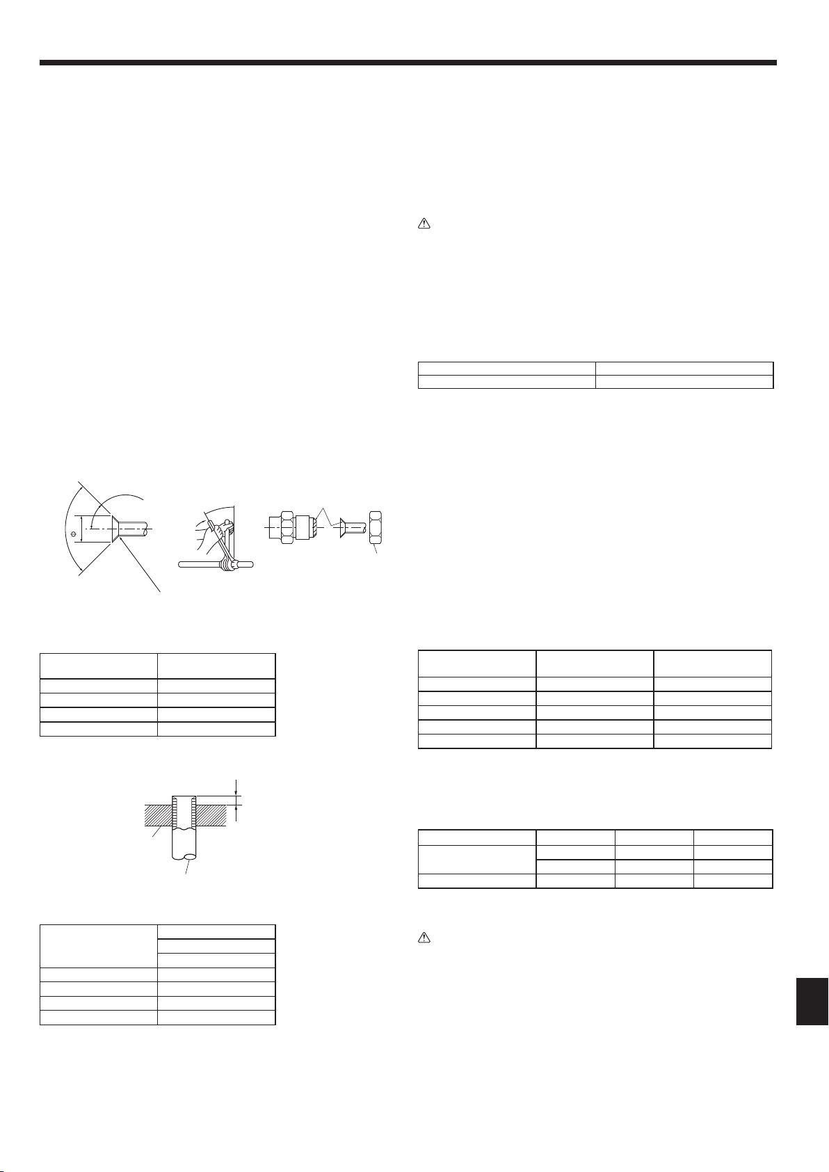
4. Прокладкатрубхладагента
A B
90°±0,5°
45°±2°
A
R0
,
4
-
R0
,
8
Fig.4-1
4.1. Мерыпредосторожности
Дляустройств,вкоторыхиспользуетсяхладагентR32/R410A
• Используйтеалкилбензольноемасло(небольшоеколичество)вкачестве
хладагентадляпокрытиясоединительныхмуфт.
• Для соединения медныхилимедносплавных бесшовных труб,предназначенныхдля хладагента,используйтемедный фосфорC1220.Используйтетрубыдляхладагентасоответствующейтолщиныдлякаждого
случая;значениятолщиныприведенывтаблицениже.Удостоверьтесь,
чтоизнутритрубычистыинесодержатникакихвредныхзагрязнителей,
таких,каксоединениясеры,окислители,мелкиймусорилипыль.
Предупреждение:
Приустановке,перемещении или обслуживаниикондиционерадля заправкитрубопроводовхладагента используйтетолько тотхладагент,
которыйуказаннанаружномустройстве.Несмешивайте егони скаким
другимхладагентоминедопускайтеналичиявоздухавтрубопроводах.
Наличие воздухавтрубопроводах можетвызывать скачкидавления, в
результатекоторыхможетпроизойтивзрывилидругиеповреждения.
Использованиелюбогохладагента,отличногоотуказанногодляэтойси-
стемы,вызоветмеханическоеповреждение,сбоивработесистемы,или
выходустройства из строя.В наихудшем случае,это можетпослужить
серьезнойпреградойкобеспечениюбезопаснойработыэтогоизделия.
ø6,35толщина0,8мм ø9,52толщина0,8мм
ø12,7толщина0,8мм ø15,88толщина1,0мм
• Неиспользуйтетрубыболеетонкие,чемуказановыше.
4.2. Соединениетруб(Fig.4-1)
• При использованиимедныхтруб, имеющихся впродаже,оберните трубы
дляжидкостиигазаимеющимисявпродажеизоляционнымиматериалами(с
теплозащитойот100°Силивыше,толщинойнеменее12мм).
• Нанеситетонкийслой маслахладагентанаконтактнуюповерхностьтруби
C
D
соединенийпередтем,какзатягиватьгайкусфланцем.
• Длязатягиваниятрубныхсоединенийиспользуйтедвагаечныхключа.
• Используйтеприлагаемоетрубноеизоляционноепокрытиедляизоляциисо-
единенийвнутреннегоблока.Тщательнокрепитеизоляцию.
• Послеподсоединениятрубхладагентаквнутреннемуприборуобязательно
проверьтесоединениятрубнаутечкугазаспомощью азота.(Проверьтеотсутствиеутечкихладагентаизтрубхладагентавовнутреннийприбор.)
• Используйтераструбнуюгайку,установленнуюнаданныйвнутреннийприбор.
• Приповторномподсоединениитрубхладагентаизготовьтезановораструбную
частьтрубы.
A Раструбныйстык-размеры
МеднаятрубаO.D.
(мм)
ø6,35 8,7 - 9,1
ø9,52 12,8 - 13,2
ø12,7 16,2 - 16,6
ø15,88 19,3 - 19,7
E
KupferrohrO.D.
(мм)
ø6,35(1/4") 0 - 0,5
ø9,52(3/8") 0 - 0,5
ø12,7(1/2") 0 - 0,5
ø15,88(5/8") 0 - 0,5
стыкадляR32/R410A
Инструментраструбного
Размерыраструба,
диаметрА(мм)
B
EПатрубок
FМеднаятруба
F
Fig.4-2
B(мм)
BМоментзатяжкигайкираструбногостыка
МеднаятрубаO.D.
(мм)
ø6,35 17 14 - 18
ø6,35 22 34 - 42
ø9,52 22 34 - 42
ø12,7 26 49 - 61
ø15,88 29 68 - 82
CНанеситемашинноемаслоохлаждениянавсюповерхностьобластиприсо-
единениямуфты.
DИспользуйтенадлежащиегайкираструбногостыка, подходящиекразмеру
трубынаружногоприбора.
Имеющийсяразмертрубы
Сторонажидкости
Сторонагаза ø12,7Ο ø15,88Ο ø15,88Ο
Ο:Креплениегайкираструбногостыкактеплообменнику,выполненноена
предприятии-изготовителе.
Предупреждение:
• Недопускайтесрываразвальцовочнойгайки!(Подвоздействиемвнутреннегодавления)
Удаление развальцовочнойгайкидолжнопроизводитьсяследующим
образом:
1.Ослабьтегайку,поканеуслышитешипящийзвук.
2.Запрещается сниматьгайку,поканестравленвесьгаз(т.е.допре-
кращенияшипящегозвука).
3.Убедитесь,чтогазполностьюстравлен,послечегоснимитегайку.
• Приустановкеприборанадежно подсоединитетрубыподачи охлаждающейжидкостидозапускакомпрессора.
Гайкараструбногоза-
тяжки(мм)
M35,50 M60
ø6,35Ο ø6,35 —
— ø9,52Ο ø9,52Ο
Моментзатяжки
(Н·м)
M71-140
215
Page 26
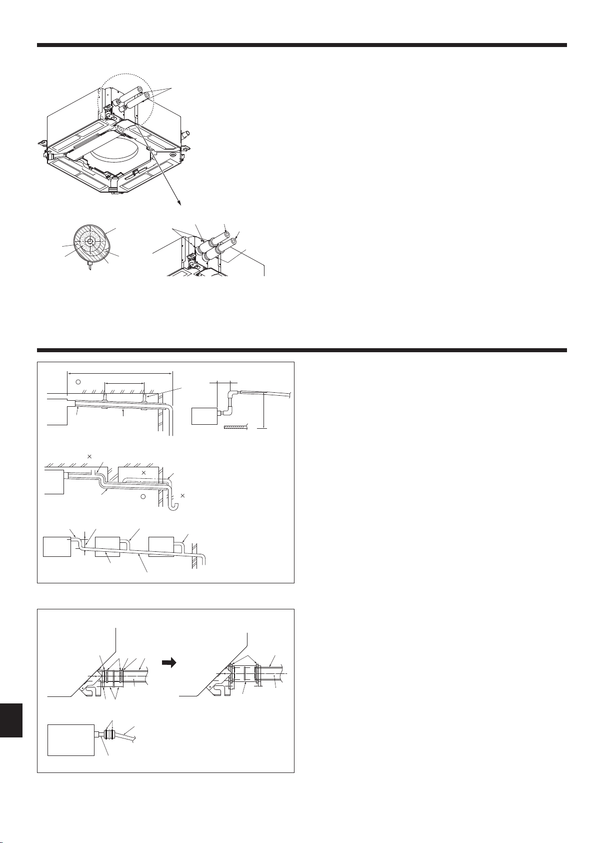
4. Прокладкатрубхладагента
AТрубахладагентаитеплоизо-
A
ляция
BПокрытиедлятруб(большое)
CПокрытиедлятруб(малое)
DТрубахладагента(газ)
EТрубахладагента(жидкость)
FЛента(большая)
GСоединениевразрезе
HТруба
IТеплоизоляция
JСжатие
Теплоизоляциядлятрубхладагента(Fig.4-3)
1. Обернитепоставляемуюизоляциюбольшогодиаметравокругтрубыдлягаза
иубедитесьвтом,чтокрайизоляциикасаетсябоковойстороныприбора.
2. Обернитепоставляемуюизоляциюмалогодиаметравокругтрубыдляжидко-
стииубедитесьвтом,чтокрайизоляциикасаетсябоковойстороныприбора.
3. Зафиксируйтеобаконцакаждогоизоляционногопокрытияспомощьюпостав-
ленныхлент.(Прикрепителентынарасстояниии20ммоткраевизоляции.)
4.3.
Длякомбинациииздвух/трех/четырехэлементов
Смотритеруководствопоустановкенаружногоприбора.
Невозможноиспользовать некоторыенаружныеприборы в одновременной
двойной/тройной/четвертнойсистеме.
G
F
B, C
I
J
H
Fig.4-3
5. Дренажныетрубы
1
A
2
3
D
F
Макс.20м
1,5-2м
B
K
B
E
F F
H
D
I
Fig.5-1
B
F
D
E
C
5.1. Дренажныетрубы(Fig.5-1)
Макс.15cм
C
F
J
L
M
D
G
• Внутренняячастьдренажнойтрубыдолжнабытьобернутавпенополиэтиле-
новыйизолирующийматериал(удельныйвес0,03;толщина9ммилиболее).
• ИспользуйтетрубыVP25 (Трубыиз ПХВ,O.D.ø32) длядренажа,при этом
обеспечьтенаклон1/100илиболее.
• Убедитесь,чтотрубныесоединениявыполненыклеемсемействаПВХ.
• Следуйтесхематическомурисункуприподсоединениитруб.
• Дляизменениянаправлениядренажаиспользуйтевходящийвкомплектпо-
ставкидренажныйшланг.
• Во времяработнадренажныхтрубахиспользуйтеопорныеметаллические
держатели.
Еслинагрузка,приложеннаяксоединительноймуфтедлядренажа,повреждает
шлангиливлияетнаегоподсоединение,томожетвозникнутьпротечкаводы.
Правильноесоединениетруб G Устанавливайтетрубыбольшогораз-
1
2 Неправильноесоединениетруб
3 Сгруппированныетрубы H Наклонвниз(1/100илибольше)
A Изоляция(9ммилибольше) I ТрубыизПХВ,O.D.ø38длясгруппиро-
B Наклонвниз(1/100илибольше)
C Поддерживающийметал
D ТрубыизПХВ,O.D.ø32 J До85см
E Сделайтееекакможнобольшей
(около10см)
F Основнойблок MЛовушказапахов
мерадлясгруппированныхтруб
ванныхтруб
(9ммизоляцияилибольше)
K Выпусквоздуха
L Поднятие
216
A AH
C KFF
6
30 30
G
D E
C
J
I
(мм)
Fig.5-2
1. Подсоединитесоединительнуюмуфтудлядренажа(входитвкомплектпо-
ставкиприбора)кдренажномупорту.(Fig.5-2)
(ЗакрепитетрубуспомощьюклеяПХВ,азатемспомощьюленты.)
Установитедренажныетрубы(закупаютсянаместе).(ТрубыизПХВ,O.D.ø32.)
2.
C
H
7
7
18
B
G
(ЗакрепитетрубуспомощьюклеяПХВ,азатемспомощьюленты.)
3. Проверьтедренирование.
4. Изолируйтедренажное отверстие и муфтуизоляционным материалом, а
затемзакрепитематериал лентой.(Изоляцияи лента входятвкомплект
прибора.)
5. Обернитеизоляциювокругтруб.(ТрубыизПХВ,O.D.ø32)
Основнойблок G
A
BИзоляция HИзоляция(приобретаетсянаместе)
CЛента(большая) IНеподготовленнаятрубаизПВХ
DДренажныйпорт(неподготов-
ленный)
EЗапас KСоединительнаямуфтадлядренажа
FСоответствие
Дренажнаятруба(ТрубыизПХВ,O.D.ø32)
JТрубыизПХВ,O.D.ø32(Наклон1/100
илиболее)
Page 27
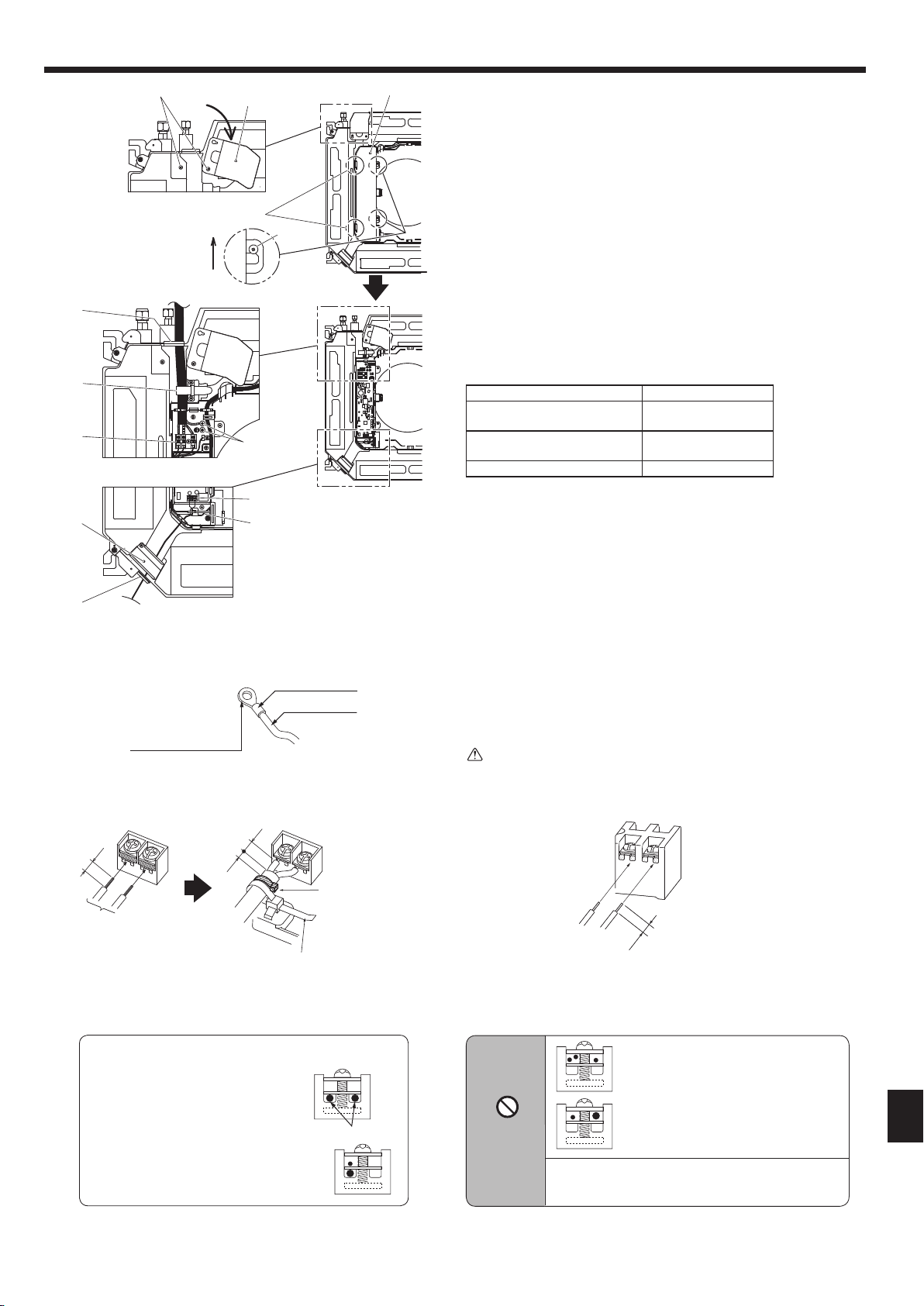
6. Электрическиеработы
[3]
G
H
J
[4]
K
L
B
[1]
Круглаяизогнутаяклемма
12
[2]
F
A
D
I
M
N
Fig.6-1
Fig.6-2
1510
E
Изоляционнаяоплетка
Электрическийкабель
C
6.1. Внутреннийприбор(Fig.6-1)
1. Ослабьте2винта,обеспечивающихфиксациюсервиснойпанелиэлектро-
проводки,азатемповернитеее.[Fig.6-11]
2. Ослабьте 2 винта,крепящихкрышкураспределительногощита, а затем
сдвиньтеее.[Fig.6-12]
Проложитесиловойкабель,соединительныйкабельвнутреннего/наружногоприбо-
3.
раикабельзаземлениячерезвводыпроводки,указанныенадиаграмме.
Поместитеэкранированнуючастьсиловогокабеляивнутреннего/наружного
соединительногокабелявраспределительныйщит.
Используйтекруглыеизогнутыеклеммыкакклеммывнутреннего/наружного
соединенияидополнительныйкомплектклеммисточникаэлектропитания.
[Fig.6-2]
Вслучаеневозможностииспользоватькруглыеизогнутыеклеммы,следуйте
порядку,указанномунаFig.6-3–6-6.
Повопросамподключениясм.п.6.1.1.и6.1.2.
4. Проложитекабельуправления черезвводыпроводки, указанные надиаграмме.[Fig.6-14,Fig.6-3]
Повопросамподключениясм.п.6.1.1.и6.1.2.
• Недопускайтеослабленияконтактныхзажимоввинтовоготипа.
Моментзатяжкивинта
Моментзатяжки(Н·м)
Клеммнаяпанельпультадистанционногоуправления
Клеммнаяпанельвнутреннегонаружногосоединения
Кабельзаземления 1,6±0,1
•
Оставьтедостаточнуюдлинукабелястем,чтобыэлектрокоробкуможнобыло
подвеситьподприборомприпроведениисервисныхработ(примерно50-100мм).
AСервиснаяпанельэлектропроводки
BВинт
CКрышкараспределительногощита
DКрюкдлявременнойфиксациикрышкираспределительногощита
EВинт
FСдвиньтекрышкураспределительногощита
GВводдлясиловогокабеляисоединительногокабелявнутреннего/наружногоприбора
HЗафиксируйтекабельнойстяжкой.
IКабельзаземления
JСоединительнаяклеммадлявнутреннего/наружногоприбора
KСервиснаяпанельдляэлектропроводки(пультдистанционногоуправления)
LВводдляпроводногопультадистанционногоуправления
MКлеммадляпроводногопультадистанционногоуправления
NЗафиксируйтекабельнойстяжкой.
Осторожно:
• Кабель пультадистанционного управлениядолженпроводиться на
определенномрасстоянии(неменее5см)откабеляисточникапитания
воизбежаниеэлектрических помех,создаваемых кабелемисточника
питания.
1,2±0,1
1,6±0,1
[Fig.6-13]
Незабудьтеподключитькабель
дистанционногоуправления
(0,3мм2)кместам,показанным
насхеме.
<Припрокладкедвухвнутренних-наружныхсоединительных
кабелей>
• Есликабелиодинакового диаметра,
вставьтеихвотверстияпообеимсторонам.
• Есликабелиразныхдиаметров,вставьтеихнаодной стороне вотдельные
отверстиятак,чтобыодинкабельрасполагалсянаддругим.
Fig.6-3
Fig.6-5
Зафиксируйтелентой4
(маленькая)вместе,показанномнасхеме
(Фиксаторкабеляпульта
дистанционногоуправления)
Кабельнаястяжка
Отверстия
12
• U-образныйпазоткрывается,еслинадавитьнаголовкувинта,когдаонослаблен.
Fig.6-4
• Запрещаетсяподключениедвухпроводов
наоднойстороне.
• Запрещаетсяподключениетрехпроводов
иболеекоднойклемме.
ПРЕДУПРЕЖДЕНИЕ
При использовании одножильного кабеля запрещается
производитьработускруглойизогнутойиликлеммойдругоготипа.
•Запрещаетсяподключение проводов
разныхдиаметров.
Fig.6-6
217
Page 28
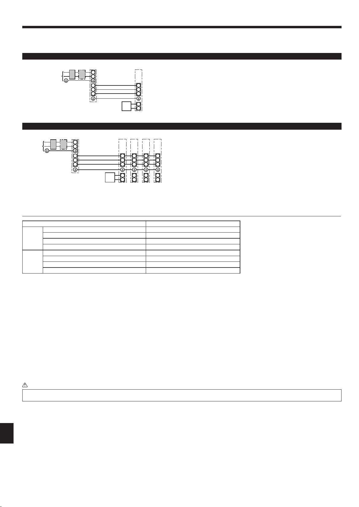
6. Электрическиеработы
6.1.1. Питаниенавнутреннийприборподаетсяотнаружногоприбора
Имеютсяследующиешаблоныподключения.
Конструкцияблокапитаниявнешнегоприборазависитотмодели.
Система1:1
D
B C
A
L
N
S1
S2
S3
E
* ПрикрепитебиркуA,прилагаемуюкруководствам,околокаждойсхемыподключениядлявнутреннегоинаружногоприборов.
Одновременнаядвойная/тройная/четвернаясистема
D
B C
A
* ПрикрепитебиркуA,прилагаемуюкруководствам,околокаждойсхемыподключениядлявнутреннегоинаружногоприборов.
L
N
S1
S2
S3
E
F
G
S1
S2
S3
1
F
2
G G G G
S1
S1
S2
S3
1
2
S1
S2
S2
S3
S3
1
1
2
2
A Источникэлектропитаниянаружногоприбора
B Прерывательутечкиназемлю
C Прерывательпроводнойцепиилиизолирующийвыключатель
D Наружныйприбор
E Соединительныепроводавнутреннегоприбора/наружногоприбора
F Пультдистанционногоуправления
G Внутреннийприбор
A Источникэлектропитаниянаружногоприбора
B Прерывательутечкиназемлю
C Прерывательпроводнойцепиилиизолирующийвыключатель
S1
S2
S3
D Наружныйприбор
E Соединительныепроводавнутреннегоприбора/наружногоприбора
F Пультдистанционногоуправления
G Внутреннийприбор
1
2
Примечание:
Невозможноиспользоватьнекоторыеприборыводновременнойдвойной/тройной/четвертнойсистеме.Дляполученияболееподробнойинформации
обратитеськруководствупоустановкенаружногоприбора.
Модельвнутреннегоприбора
Внутреннийприбор-Наружныйприбор
)
2
Заземлениевнутреннего/наружногоприбора *1
Заземлениевнутреннегоприбора
ПроводNo×
размер(мм
Электропроводка
Пультдистанционногоуправления-Внутреннийприбор
*1
*2
Внутреннийприбор(Обогреватель)L-N
Внутреннийприбор-НаружныйприборS1-S2 *3
цепи
Внутреннийприбор-НаружныйприборS2-S3 *3
Мощность
Пультдистанционногоуправления-Внутреннийприбор
*1.<Длявнешнихприборовтипов35-140>
Макс.45м
Еслииспользуется2,5мм
Еслииспользуется2,5мм
<Длявнешнегоприборатипа200/250>
Макс.18м
Еслииспользуется2,5мм
Еслииспользуется4мм
Еслииспользуется6мм
*2.Макс.500м
(Прииспользовании2пультовдистанционногоуправлениядлинапроводкиихкабелейнедолжнапревышать200м.)
*3.ВеличиныНЕвсегдаизмереныотносительноземли.
РазницапотенциаловвыводовS3иS2составляет24Впостоянноготока.МеждувыводамиS3иS1нетэлектрическойизоляцииспомощьютрансформатораилидругогоустройства.
2
,макс.50м
2
иотдельныйS3,макс.80м
2
,макс.30м
2
иотдельныйS3,макс.50м
2
иотдельныйS3,макс.80м
*3
PLA
3×1,5(полярный)
1×Мин.1,5
1×Мин.1,5
2×0,3(неполярный)
—
230 Вольтперем.тока
24 Вольтпост.тока
12 Вольтпост.тока
Примечания: 1.Диаметрпроводовдолженсоответствоватьприменимымместныминациональнымнормам.
2. СиловыекабелиикабелисоединенияВнутреннего/Наружногоприборанедолжныбытьлегчеэкранированногогибкогопроводаиз
полихлоропрена(модель60245IEC57).
3. Длинаустанавливаемогокабелязаземлениядолжнапревышатьдлинудругихкабелей.
4. Полярностисоединительныхпроводоввнутреннегоинаружногоприборов.Убедитесьвсоответствииномераклемм(S1,S2,S3)про-
водам.
5. Кабельпультадистанционного управлениядолженпроводитьсянаопределенномрасстоянии(неменее5см)откабеляисточника
питаниявоизбежаниеэлектрическихпомех,создаваемыхкабелемисточникапитания.
Предупреждение:
Никогданеподсоединяйтевнахлестсиловойкабельилисоединительныйкабельвнешнегопитания.Этоможетпривестикзадымлению,возгораниюилинеисправности.
218
Page 29
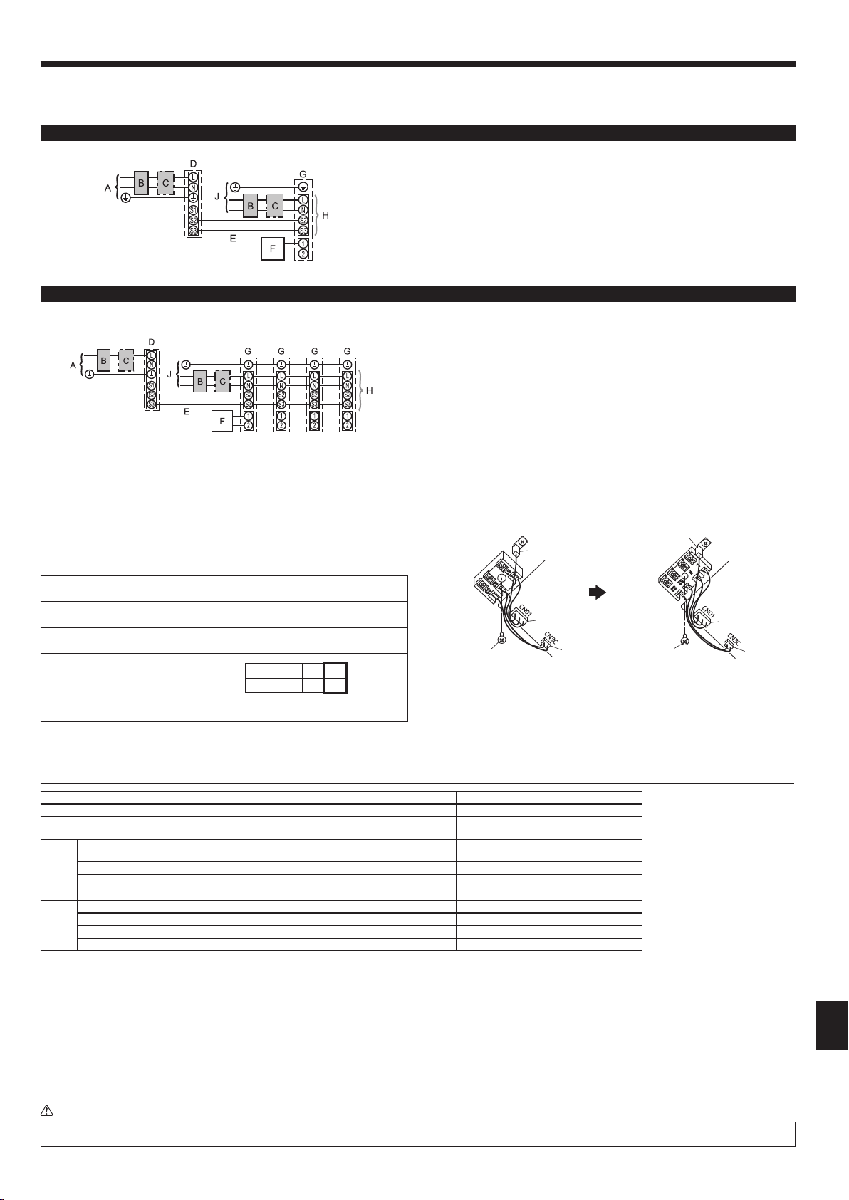
6. Электрическиеработы
6.1.2. Отдельныеисточникиэлектропитаниядлявнутреннегоприбора/наружногоприбора(ТолькодляпримененияPUHZ/PUZ)
Имеютсяследующиешаблоныподключения.
Конструкцияблокапитаниявнешнегоприборазависитотмодели.
Система1:1
* Требуетсякомплектклеммисточникаэлектропитаниявнутреннегоприбора.
* ПрикрепитебиркуB,прилагаемуюкруководствам,околокаждойсхемыподключениядлявнутреннегоинаружногоприборов.
Одновременнаядвойная/тройная/четвернаясистема
* Требуютсякомплектыклеммисточникаэлектропитаниявнутреннегоприбора.
* ПрикрепитебиркуB,прилагаемуюкруководствам,околокаждойсхемыподключениядлявнутреннегоинаружногоприборов.
A Источникэлектропитаниянаружногоприбора
B Прерывательутечкиназемлю
C Прерывательпроводнойцепиилиизолирующийвыключатель
D Наружныйприбор
E Соединительныепроводавнутреннегоприбора/наружногоприбора
F Пультдистанционногоуправления
G Внутреннийприбор
H Дополнительно
J Источникэлектропитаниявнутреннегоприбора
A Источникэлектропитаниянаружногоприбора
B Прерывательутечкиназемлю
C Прерывательпроводнойцепиилиизолирующийвыключатель
D Наружныйприбор
E Соединительныепроводавнутреннегоприбора/наружногоприбора
F Пультдистанционногоуправленияr
G Внутреннийприборit
H Дополнительно
J Источникэлектропитаниявнутреннегоприбора
Примечание:
Невозможноиспользоватьнекоторыеприборыводновременнойдвойной/тройной/четвертнойсистеме.Дляполученияболееподробнойинформации
обратитеськруководствупоустановкенаружногоприбора.
Еслиувнутреннегоинаружногоприборовразличныеисточникиэлектропитания,см.таблицуниже.
Прииспользованиикомплекта клемм источникаэлектропитаниявнутреннего прибора замените
проводкураспределительнойкоробкивнутреннего приборавсоответствиисрисунком справаи
<Заменаклеммнойкоробкивнутреннегоприбора>
3
2
изменитенастройкимикропереключателяпанелиуправлениянаружногоприбора.
Комплектклеммисточникаэлектропитаниявнутреннегоприбора(дополнительно)
Изменениесоединенияразъемараспределительнойкоробкивнутреннегоприбора
Бирка,прикрепленнаяоколокаждойсхемыподключениядлявнутреннегоинаружногоприборов
Настройка микропереключателянаружного
прибора(толькоприиспользованииотдельных
источниковэлектропитаниядля внутреннего
прибора/наружногоприбора)
Установитепереключатель
SW8-3вположениеON(ВКЛ.).
* Имеетсятритипабирок(биркиA,BиC).Прикрепитесоответствующиебирки
кблокамвсоответствиисметодомподключенияпроводки.
Модельвнутреннегоприбора PLA
Электропитаниевнутреннегоприбора ~/N(однофазный),50Гц,230В
Входнаямощностьвнутреннегоприбора
Главныйвыключать(Прерыватель)
Электропитаниевнутреннегоприбора&
)
2
Заземлениепитаниявнутреннегоприбора
Внутреннийприбор-Наружныйприбор *2 2×Мин.0,3
Заземлениевнутреннего/наружногоприбора –
ПроводNo×
размер(мм
Электропроводка
Пультдистанционногоуправления-Внутреннийприбор *3 2×0,3(неполярный)
ВнутреннийприборL-N *4 230Вольтперем.тока
Внутреннийприбор-НаружныйприборS1-S2 –
цепи
Внутреннийприбор-НаружныйприборS2-S3 *4 24Вольтпост.тока
Мощность
Пультдистанционногоуправления-Внутреннийприбор *4 12Вольтпост.тока
*1.Используйтевыключательтокаутечкиназемлю(NV)срасстояниеммеждуконтактамипокрайнеймере3,0ммдлякаждогополюса.
Дляотключениявсехактивныхфазовыхпроводовэлектропитаниянеобходимоустановитьпрерыватель.
*2.Макс.120м
*3.Макс.500м
(Прииспользовании2пультовдистанционногоуправлениядлинапроводкиихкабелейнедолжнапревышать200м.)
*4.ВеличиныНЕвсегдаизмереныотносительноземли.
Требуется
Требуется
Требуется
ON
OFF 1 2
2
4
ОтсоединитеразъемCN3C(синийцвет)
3
(SW8)
1
отплатыуправлениявнутреннегоблока.
2 ОтсоединитеразъемCN01(черный
цвет)отплатыуправлениявнутреннего
блока.
3 Отсоединитестолбиковыйвывод.
4 Выкрутитевинтизклеммнойкоробки.
*1 16 A
1
3×Мин.1,5
Установитедополнительныйкомплектклемм
источникапитания.Подробноеописаниесм.
вруководствепоустановке,прилагаемом
кдополнительномукомплектуклеммисточникапитания.
1 Зафиксируйтеклеммнуюкоробкуспо-
2 Вставьтестолбиковыйвывод.
3 ПодсоединитеразъемCN01(черныйцвет)
4 ПодсоединитеразъемCN3С(синийцвет)
1
мощьювинта.
кплатеуправлениявнутреннегоблока.
кплатеуправлениявнутреннегоблока.
3
4
Примечания: 1.Диаметрпроводовдолженсоответствоватьприменимымместныминациональнымнормам.
2.
3. Длинаустанавливаемогокабелязаземлениядолжнапревышатьдлинудругихкабелей.
СиловыекабелиикабелисоединенияВнутреннего/Наружногоприборанедолжныбытьлегчеэкранированногогибкогопроводаизполихлоропрена(модель60245IEC57).
4. Кабельпультадистанционногоуправлениядолженпроводитьсянаопределенномрасстоянии(неменее5см)откабеляисточника
питаниявоизбежаниеэлектрическихпомех,создаваемыхкабелемисточникапитания.
Предупреждение:
Никогданеподсоединяйтевнахлестсиловойкабельилисоединительныйкабельвнешнегопитания.Этоможетпривестикзадымлению,возгораниюилинеисправности.
219
Page 30
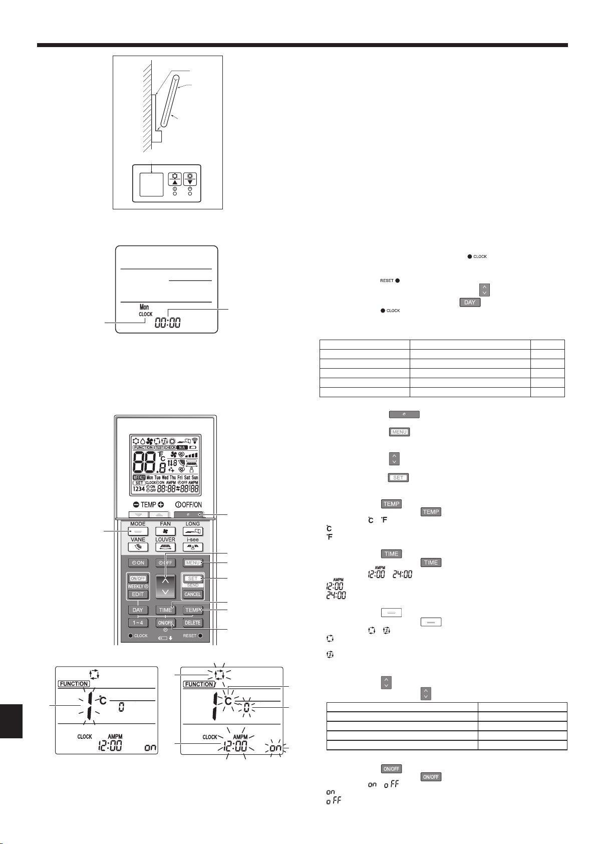
6. Электрическиеработы
1
B
C
A
2
D
Fig.6-7
B
A
Fig.6-8
1
7
4
2
3
6
5
8
C
A
B
Fig.6-9 Fig.6-10
6.2. Пультдистанционногоуправления
6.2.1. Дляпроводногопультадистанционногоуправления
1)Настройкадвухпультовдистанционногоуправления
Еслиподключеныдвапультадистанционногоуправления,настройте
одинкак“Main”(Главный),адругой-как“Sub”(Подчиненный).Процедуры
настройкиприводятсявразделе“Выборфункцийпультадистанционного
управления”вруководствепоэксплуатациивнутреннегоприбора.
6.2.2. Длябеспроводногопультадистанционногоуправления
1)Местоустановки
•
Место,гдепультДУнеподверженвоздействиюпрямыхсолнечныхлучей.
• Место,гдепоблизостинетисточникатепла.
•
Место,гдепультДУнеподверженвоздействиюхолодногоилигорячеговоздуха.
• Место,гдепультомДУможнолегкоуправлять.
• Место,гдепультДУбудетнедоступендетям.
2)Методустановки(Fig.6-7)
1Прикрепитедержательпультадистанционногоуправлениявнужном
местеспомощью2самонарезающихвинтов.
2
Установитенижнийконецпультадистанционногоуправлениявдержатель.
A ПультдистанционногоуправленияBСтенаCПанельдисплеяDПриемник
• Сигналможетпередаватьсянарасстояниеприблизительнов7м(по
прямойлинии)вдиапазоне45градусовслеваисправаотцентральной
осиприемника.
3)Настройка(установкавремени)(Fig.6-8)
1 Установитебатарейкиилинажмитекнопку
томсострымконцом.
Индикация[CLOCK](ЧАСЫ)Aи[:]Bбудетмигать.
2Нажмитекнопку
3Дляустановкивременипользуйтеськнопками
Чтобыустановитьдень,нажмитекнопку
4Нажмитекнопку
Загоритсяиндикация[CLOCK](ЧАСЫ)и[:].
4)Первоначальнаянастройка
Следующиенастройкимогутбытьвыполненыврежимепервоначальнойнастройки.
Элемент Настройка Fig.6-10
Единицатемпературы °C/°F
Отображениевремени
АВТОМАТИЧЕСКИЙрежим Одиночнаяуставка/двойнаяуставка
Номерпары 0-3
Подсветка On/Off(Вкл./Выкл.)
4-1.Переключениеврежимпервоначальнойнастройки
1.Нажмитекнопку
воздуха.
2.Нажмитекнопку 2.
ОтобразитсяэкраннастройкиFunction(Настройкафункций)ибудет
мигатьчисловоезначениефункцииA.(Fig.6-9)
Нажмитекнопку
3.Убедитесь,чтоотображаетсячисловоезначениефункции“1”,затем
нажмитекнопку
Отобразитсяэкраннастройкииндикации.(Fig.6-10)
4-2.ИзменениеединицытемпературыA
Нажмитекнопку
Прикаждомнажатиикнопки
элементами
:температураотображаетсявградусахшкалыЦельсия.
:температураотображаетсявградусахшкалыФаренгейта.
4-3.ИзменениеотображениявремениB
Нажмитекнопку
Прикаждомнажатиикнопки
элементами и .
:времяотображаетсяв12-часовомформате.
:времяотображаетсяв24-часовомформате.
4-4.ИзменениеАВТОМАТИЧЕСКОГОрежимаC
Нажмитекнопку
Прикаждомнажатиикнопки
элементами
:режимAUTO(АВТОМАТИЧЕСКИЙ)работаеткакобычныйавтомати-
ческийрежим.
:режимAUTO(АВТОМАТИЧЕСКИЙ)работаетсиспользованием
двойныхуставок.
4-5.ИзменениеномерапарыD
A
D
Нажмитекнопку
Прикаждомнажатиикнопки
Номерпарыбеспроводногопультадистанционногоуправления Печатнаяплатавнутреннегоблока
E
4-6.ИзменениенастройкиподсветкиE
Нажмитекнопку
Прикаждомнажатиикнопки
элементами
:подсветказагораетсяпринажатиикнопки.
:подсветканезагораетсяпринажатиикнопки.
каким-нибудьпредметомсострымконцом.
каким-либопредметомсострымконцом.
12-часовойформат/24-часовойформат
1,чтобыостановитьработукондиционера
4,чтобыизменитьчисловоезначениефункции.
3.
5.
5происходитпереключениемежду
и .
6.
6происходитпереключениемежду
7.
7происходитпереключениемежду
и .
4.
4происходитсменаномеровпары0–3.
0 Первоначальнаянастройка
1 РазомкнутьJ41
2 РазомкнутьJ42
3 РазомкнутьJ41,J42
8.
8происходитпереключениемежду
и .
каким-нибудьпредме-
.
.
A
B
C
D
E
220
Page 31

6. Электрическиеработы
Service menu
Test run
Input maintenance info.
Function setting
Check
Self check
Main menu:
Cursor
F1 F2 F3 F4
Monitor:
F1 F2 F3 F4
Fig.6-11 Fig.6-12
Function setting
Ref. address
Mode 1
Mode 2
Mode 3
Mode 4
Request:
Cursor Cursor
F1 F2 F3 F4
Grp.
Request:
F1 F2 F3 F4
Fig.6-13 Fig.6-14
Function setting
Ref. address
Grp.
Sending data
Function setting
Ref. address
Unit No.
Cursor Address
Ref. address
Mode 7
Mode 8
Mode 9
Mode 10
Cursor Cursor
Grp./1/2/3/4/All
Function setting
Unit # 1
6.3. Установкифункций
6.3.1. Спомощьюпроводногопультадистанционногоуправления
1 (Fig.6-11)
• Выберите в Главномменюпункт“Service” (Сервисное обслуживание) и
нажмитекнопку[ВЫБОР].
• Спомощьюкнопки[F1]или[F2]выберитепункт“Functionsettings”(Настройка
функций)инажмитекнопку[ВЫБОР].
2 (Fig.6-12)
• Установитеадресаблоковохлаждениявнутреннихблоковиномераблоков
спомощьюкнопок[F1]–[F4],азатемнажмитекнопку[ВЫБОР],чтобыподтвердитьнастройки.
<Проверкавнутреннегоблока№.>
Когдабудетнажатакнопка[ВЫБОР],запуститсявентиляторсоответствующеговнутреннегоблока.Еслиработаетодинобщийблокиликогдаработают
всеблоки,навсехвнутреннихблокахдлявыбранногоадресахладагента
будутзапущенывентиляторы.
3 (Fig.6-13)
• После завершениясбораданных внутренних блоковтекущиенастройки
будутотмеченыподсветкой.Неподсвеченныепунктыуказывают,чтонастройкифункций выполненынебыли.Видэкрана зависитот параметра
“UnitNo.”(Устр.№).
4 (Fig.6-14)
• С помощью кнопок[F1]и [F2] переместите курсордлявыбораномера
режимаиизменитеномеркнопкой[F3]или[F4].
5 (Fig.6-15)
• Послезавершениянастройкинажмитекнопку[ВЫБОР],чтобыотправить
выбранныезначенияизконтроллерадистанционногоуправлениявовнутренниеблоки.
• ПослеуспешногозавершенияпередачиповторнооткроетсяэкранНастройкафункций.
F1 F2 F3 F4
Fig.6-15
Fig.6-16
Fig.6-18
6.3.2. Спомощьюбеспроводногопультадистанционного
управления
1 Переходврежимвыборафункции
Нажмитеиудерживайтекнопку
(Начнитеэтуоперациюсвыключенногодисплеядистанционногопульта
управления.)
Загорится[CHECK](ПРОВЕРКА),будетмигать“00”.(Fig.6-16)
Дляустановкизначения"50"пользуйтеськнопкой
Направьтебеспроводнойпультдистанционногоуправлениянаприемник
A
сигналавнутреннегоблокаинажмитекнопку
2 Установканомераблока
Дляустановкиномераблокапользуйтеськнопками A. (
Fig.6-17
B
Fig.6-19
Направьтебеспроводнойпультдистанционногоуправлениянаприемник
сигналавнутреннегоблокаинажмитекнопку
3 Выборрежима
Дляустановкиномерарежимапользуйтеськнопками
Направьтебеспроводнойпультдистанционногоуправлениянаприемниксигна-
лавнутреннегоблокаинажмитекнопку
Номертекущейнастройки: 1=1сигнал(1секунда)
2=2сигнала(1секундакаждый)
3=3сигнала(1секундакаждый)
4 Выборномеранастройки
Длясменыномеранастройкипользуйтеськнопками C.(Fig.6-19)
Направьтебеспроводнойпультдистанционногоуправлениянаприемниксигна-
лавнутреннегоблокаинажмитекнопку
5 Выборнесколькихфункцийодновременно
C
Повторяйтевыбордействий3и4дляпоследовательногоизмененияна-
строекнесколькихфункций.
6 Завершениевыборафункций
Направьтебеспроводнойпультдистанционногоуправлениянадатчик
внутреннегоблокаинажмитекнопку
Примечание:
Принеобходимостивыполнитевышеприведенныенастройкидля
устройствсерииMr.Slim.
•
Втаблице1приведеныпараметрынастройкидлякаждогономера
режима.
•
Обязательнозапишитенастройкидлявсехфункций,есликакие-либоиз
первоначальныхнастроекбылиизмененыпослезавершениямонтажных
работ.
неболее5секунд.
.
.
.
.
.
.
Fig
.6-17)
B.(Fig.6-18)
221
Page 32
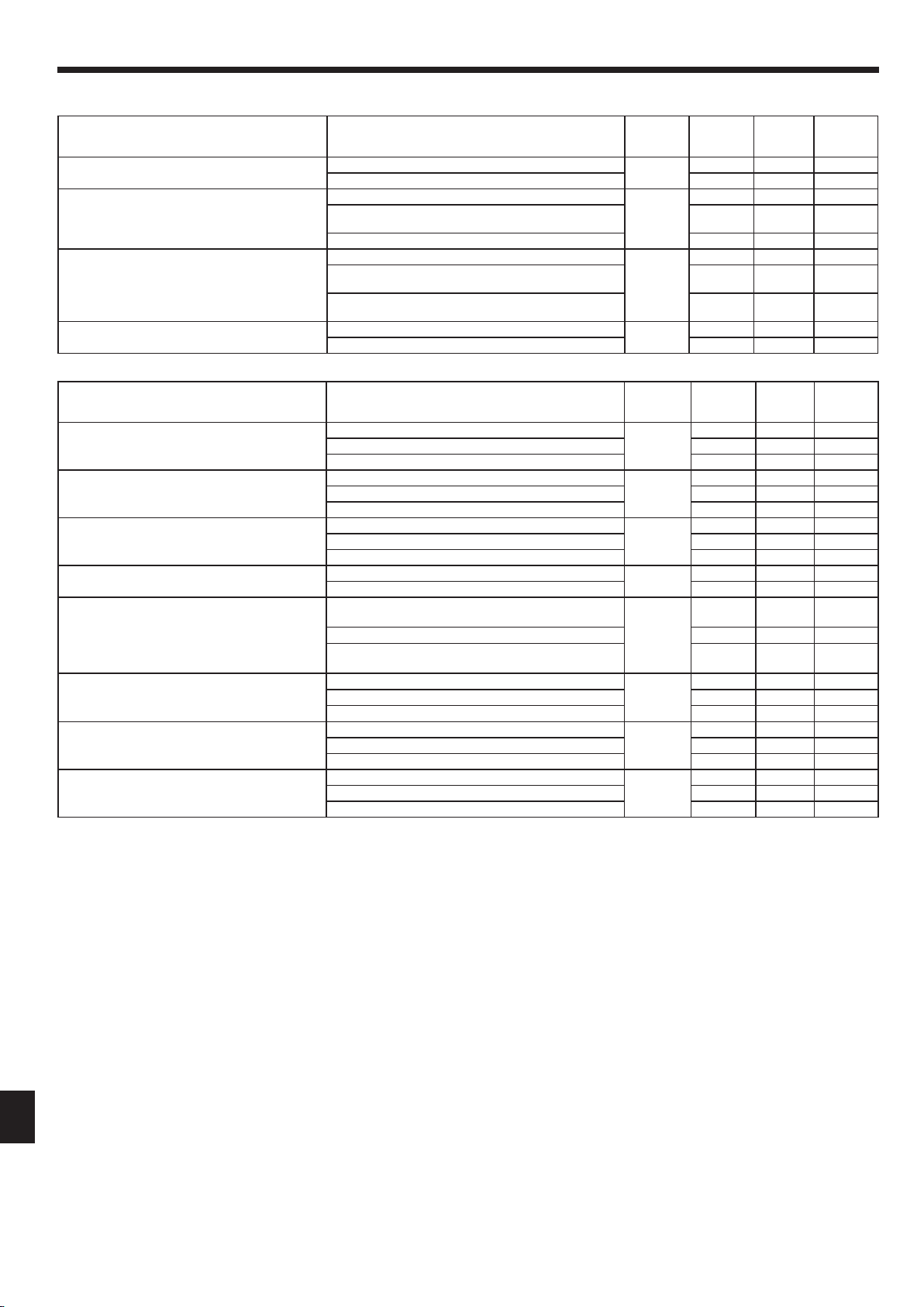
6. Электрическиеработы
Таблицафункций(Таблица1)
Выберитеномерприбора00
Режим Установки
Автоматическоевосстановлениепослесбоя
питания
Определениетемпературывпомещении Средняявеличинаприработевнутреннегоприбора
ПодсоединяемостьLOSSNAY Неподдерживается
Напряжениевсетиэлектропитания 240В
Выберитеномераприбораот01до03иливсеприборы(AL[проводнойпультдистанционногоуправления]/07[беспроводнойпультдистанционногоуправления])
Режим Установки
Знакфильтра 100часов
Скоростьвентилятора Бесшумный(низкийпотолок)
Кол-вовыдувныхотверстий 4направления
Установленныеопции(высокоэффективный
фильтр)
Установказаслонкивверх/вниз Настройкадвиженияпонисходящей линии (Настройка
Расположение3D-датчикаi-see
Настройкавысотыпотолка3D-датчикаi-see
(приустановкепанели3D-датчикаi-see)
Скоростьвентиляторавовремяотключения
термостатаохлаждения
*1Привозобновленииподачиэлектропитаниякондиционерзапуститсячерез3минуты.
*2Первоначальнаянастройкаустройстваавтоматическоговключенияпослесбояэлектропитаниязависитотсхемыподсоединениявнешнегоприбора.
*3Еслиположениеугловойпанели3D-датчикаi-seeизменилось,изменитеэтотрежим.См.стр.228.
Отсутствует
Имеется *1 2 Ο*2
Устанавливаетсяспультадистанционногоуправления
внутреннегоприбора
Внутреннийдатчикпультадистанционногоуправления 3
Поддерживается(внутреннийприборнеоборудован
механизмомвсасываниянаружноговоздуха)
Поддерживается(внутреннийприбороборудованмеханизмомвсасываниянаружноговоздуха)
220В,230В 2 Ο
2500часов 2 Ο
Нетиндикаторазнакафильтра 3
Стандартный 2 Ο
Высокая 3
3направления 2
2направления 3
Неподдерживается
Поддерживается 2
углазаслонки3)
Средняянастройка(Настройкауглазаслонки1)
Настройкабессквозняковойвентиляции(Настройкаугла
заслонки2)
Положение1
Положение2
Положение3 (Поумолчанию)
Низкийпотолок(высотапотолка:менее2,7м)
Стандарт(высотапотолка:2,7–3,5м) 2 Ο
Высокийпотолок(высотапотолка:3,5–4,5м) 3
Установкаскоростивентилятора
Остановлено 2
Сверхнизкая 3 Ο
Номер
режима
01
02
03
04
Номер
режима
07
08
09
10
11
12 *3
26
27
Номер
установки
Номер
установки
Первона-
чальная
настройка
1
1 Ο
2
1 Ο
2
3
1
Первона-
чальная
настройка
1
1
1 Ο
1 Ο
1
2
3 Ο
1
2
3 Ο
1
1
установка
установка
222
Page 33
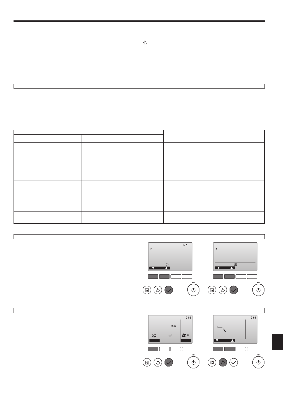
7. Выполнениеиспытания
7.1. Передпробнымпрогоном
► Послезавершенияустановки,прокладкитрубиэлектропроводкивнутреннего
инаружногоприборовпроверьтеотсутствиеутечкихладагента,слабыхсоединенийкабеляпитанияилипроводовуправленияинеправильнойполярности,
атакжеубедитесь,чтовсефазыпитанияподключены.
► Измерьтесопротивлениемеждутерминаламиисточникаэлектропитания
изаземлениемсиспользованием500-вольтногомеггераиубедитесь,что
сопротивлениесоставляетнеменее1,0МΩ.
7.2. Выполнениеиспытания
7.2.1.
Использованиепроводногопультадистанционногоуправления.
■ Передпробнымпускомвнимательнопрочтитеруководствопоэксплуатации.(Особенноэтокасаетсяуказанийпобезопасности)
Шаг1 Включитепитание.
● Пультдистанционногоуправления:системапереходитврежимзапуска,индикаторпитания(зеленый)пультадистанционногоуправленияначинаетмигатьи
отображаетсясообщение“PLEASEWAIT(Ждите)”.Вэтотмоментпультдистанционногоуправлениянедоступендляопераций.Передиспользованиемпульта
дистанционногоуправлениядождитесьудалениясдисплеясообщения“PLEASEWAIT(Ждите)”.Сообщение“PLEASEWAIT(Ждите)”отображаетсявтечение
приблизительно3минутпослевключенияпитания.
● Платауправлениявнутреннегоблока:индикатор1загорается,индикатор2загорается(еслиадресравен0)илигаснет(еслиадреснеравен0),индикатор3
мигает.
● Платауправлениянаружногоблока:индикатор1(зеленый)ииндикатор2(красный)загораются.(Послезавершенияпроцедурызапускасистемыиндикатор2
гаснет.)Еслинаплатеуправлениянаружногоблокаиспользуетсяцифровойдисплей,каждуюсекундупопеременноотображаютсясимволы[-]и[-].
Еслипослевыполненияпроцедурвшаге2ипосленегооперацииневыполняютсянадлежащимобразом,проверьтеиустранитеследующиепроблемы.
(Симптомы,описанныениже,могутпроявлятьсяврежимепробногопуска.“Startup(Запуск)”втаблицеобозначаетсяиндикацией,описаннойвыше.
Симптомыврежимепробногопуска
Дисплейпультадистанционногоуправления
Напультедистанционногоуправления
отображается сообщение“PLEASEWAIT
(Ждите)”,пультдляоперацийнедоступен.
После включенияпитанияв течение 3
минутотображаетсясообщение“PLEASE
WAIT(Ждите)”,затемотображается код
ошибки.
Дисплейнезагораетсядажепривключении питаниянапульте дистанционного
управления. (Незагораетсяиндикатор
работы.)
Дисплейзагорается,новскорегаснетдаже
приработеспультом дистанционного
управления.
ИндикацияПЛАТЫНАРУЖНОГОБЛОКА
<>обозначаетцифровойдисплей.
Послеотображениясообщения“Startup (Запуск)”
загораетсятолькозеленыйиндикатор.<00>
Послеотображениясообщения“Startup (Запуск)”
попеременновспыхиваютоднократнозеленый и
однократнокрасныйиндикаторы.<F1>
Послеотображениясообщения“Startup (Запуск)”
попеременновспыхиваютоднократнозеленый и
дваждыкрасныйиндикаторы.<F3,F5,F9>
Послеотображениясообщения“Startup (Запуск)”
попеременновспыхиваютдваждызеленыйиоднократнокрасныйиндикаторы.<EA.Eb>
Послеотображениясообщения“Startup (Запуск)”
загораетсятолькозеленыйиндикатор.<00>
Послеотображениясообщения“Startup (Запуск)”
загораетсятолькозеленыйиндикатор.<00>
►
Запрещаетсявыполнятьэтотзамернатерминалахпроводахуправления
(цепьнизкогонапряжения).
Предупреждение:
Непользуйтесь кондиционеромвоздуха, еслисопротивлениеизоляции
Ω
ниже1,0М
.
)
Причина
• Послевключенияпитаниявтечение3минутвовремязапуска
системынадисплеебудетотображатьсясообщение“PLEASE
WAIT”(Ждите).(Нормальныйрежим)
• Неверноеподключениекклеммнойколодкенаружногоблока
(R,S,TиS
,S2,S3.)
1
• Разомкнутконтактзащитногоустройстванаружногоблока.
• Неверное подключение проводовмеждувнутренним и наружнымблоками(невернаяполярностьподключенияS
S
).
3
• Проводпередачиданныхпультадистанционногоуправления
закорочен.
•
Отсутствуетнаружныйблоксадресом0.(Адреснеравен0.)
• Разомкнутпроводпередачиданныхпультадистанционного
управления.
• После отменывыборафункции, операции недоступны в
течение30секунд.(Нормальныйрежим)
,S2,
1
Шаг2 Включитенапультедистанционногоуправлениярежим“Testrun”(Пробныйпуск).
1 Выберитережим“Testrun”(Пробныйпуск)вСервисномменюинажмитекнопку
[ВЫБОР].(Fig.7-1)
2 Выберитережим“Testrun”(Пробныйпуск)вМенюпробногопускаинажмите
кнопку[ВЫБОР].(Fig.7-2)
3 Запускаетсярежим“Пробныйпуск”иотображаетсяэкранпробногопуска.
Test run
Input maintenance info.
Function setting
Check
Self check
unem ecivreS
:unem niaM
rosruC
F1 F2 F3 F4
Fig.7-1
Шаг3 Выполнитепробныйпускипроверьтетемпературувоздушногопотокаиавтоматическуюработужалюзи.
1 Дляизменениярежимаработынажмитекнопку[F1].(Fig.7-3)
Режимохлаждения:убедитесь,чтоизблокапоступаетохлажденныйвоздух.
Режимнагревания:убедитесь,чтоизблокапоступаетнагретыйвоздух.
2 Нажмитекнопку[ВЫБОР] дляотображенияэкрана работыжалюзи,затем
нажмитекнопку[F1]и [F2] для проверкиавтоматического режимаработы
жалюзи.(Fig.7-4)
Нажмитекнопку[ВОЗВРАТ]длявозвратакэкранупробногопуска.
Cool
Mode Fan
Pipe
Switch disp.
RemainTest run
Auto
F1 F2 F3 F4
Fig.7-3
Test run menu
Test run
Drain pump test run
Service menu:
Cursor
F1 F2 F3 F4
Fig.7-2
Remain
Vane
F1 F2 F3 F4
Fig.7-4
223
Page 34
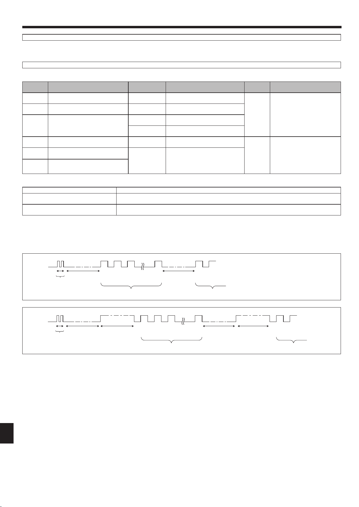
7. Выполнениеиспытания
Шаг4 Проверкаработывентиляторанаружногоблока.
Скоростьвращениявентиляторанаружногоблокарегулируетсядляуправления работойустройства.В зависимостиотатмосферныхусловийвентиляторвращаетсяснизкойскоростью,покаэтогобудетдостаточнодлянормальнойработы.Наружныйветерможетпривестикостановкевентилятораилиеговращениюв
обратномнаправлении,однакоэтонеявляетсяпроблемой.
Шаг5 Остановкапробногопуска.
1Дляостановкипробногопусканажмитекнопку[ВКЛ/ВЫКЛ].(ОтображаетсяменюПробногопуска.)
Примечание:Еслинадисплееотображаетсякодошибки,см.таблицуниже.
ЖК-
дисплей
P1 Ошибкадатчикавпуска P9
Ошибкадатчикатрубопровода
P2
(трубопроводдляжидкости)
Разъединенконтактпереключателя
P4
дренажногослива(CN4F)
Защитаотпереполнениядренажной
P5
системы
Защитасистемыохлаждения/
P6
нагревания
P8 Ошибкатемпературытрубопровода
Описаниесбоя ЖК-дисплей Описаниесбоя
Ошибкадатчикатрубопровода
(двойнойтрубопровод)
PA
Pb
PL
FB
Ошибкапротечки(система
хладагента)
Ошибкамоторавентилятора
внутреннегоблока
Ненадлежащеефункционирование
контурахладагента
Ошибкаплатыуправления
внутреннегоблока
U*,F*
(*обозначение
буквенно-
цифрового
Нарушениеработынаружногоблока.
См.схемусоединенийнаружного
блока.
символа,кромеFB.)
Описаниеиндикаторовдисплеясм.втаблицениже(индикаторы1,2и3)наплатеуправлениявнутреннегоблока.
Индикатор1(питаниемикрокомпьютера) Индикаторподачипитания.Этотиндикатордолженгоретьпостоянно.
Индикатор2(питаниепультадистанционного
управления)
Индикатор3(связьвнутреннего/наружного
блоков)
Указывает,подаетсялипитаниенапроводнойпультдистанционногоуправления.Данныйиндикаторзагорается
толькодлявнутреннегоблока,подключенногокнаружномублокуиимеющегоадрес0.
Указываетнасвязьмеждувнутренниминаружнымблоками.Этотиндикатордолженпостоянномигать.
ЖК-
дисплей
E0–E5
E6–EF
Описаниесбоя
Ошибкасвязимеждупультом
дистанционногоуправленияи
внутреннимблоком
Ошибкасвязимеждувнутренним
инаружнымблоками
7.3. Самодиагностика
■ Подробноеописаниесм.вруководствепоустановке,прилагаемогокпультудистанционногоуправления.
• Дополнительныесведенияпокодампроверкиприводятсявследующихтаблицах.(беспроводногопультадистанционногоуправления)
[ШаблонвыводаA]
Звуковойсигнал
ШаблонмиганияРАБОЧЕГО
СВЕТОВОГО
ИНДИКАТОРА
[ШаблонвыводаB]
Звуковойсигнал
ШаблонмиганияРАБОЧЕГО
СВЕТОВОГО
ИНДИКАТОРА
Сигнал
Выкл
Запускается
самопроверка
(Полученсигнал
запуска)
Сигнал Сигнал Сигнал Сигнал Сигнал Сигнал Сигнал
Запускается
самопроверка
(Полученсигнал
запуска)
Ок.2,5сек.
Выкл
Ок.2,5сек.
Сигнал Сигнал Сигнал Сигнал Сигнал Сигнал
1-ый 2-ой 3-ий
Вкл
Вкл
0,5сек.
Числомиганий/звуковвшаблонеуказываетнакодпроверкивследующейтаблице(т.е.,n=5означает“P5”)
Ок.3сек.
Вкл
0,5сек.
0,5сек.
Вкл
Числомиганий/звуковвшаблонеуказываетнакодпроверкивследующейтаблице(т.е.,n=5означает“U2”)
n-ый
Вкл
0,5сек.
1-ый 2-ой 3-ий n-ый 1-ый 2-ой
Вкл
Вкл
0,5сек.
0,5сек.
Ок.2,5сек.
Вкл
0,5сек.
Выкл
1-ый 2-ой
Вкл
0,5сек.
Числомиганий/звуковвшаблонеуказываетнакод
проверкивследующейтаблице
Вкл
0,5сек.
···Повторный
Вкл
0,5сек.
Выкл
Ок.2,5сек.
Вкл
Ок.3сек.
Числомиганий/звуковвшаблонеуказываетна
кодпроверкивследующейтаблице
Вкл
0,5сек.
···Повторный
Вкл
0,5сек.
224
Page 35
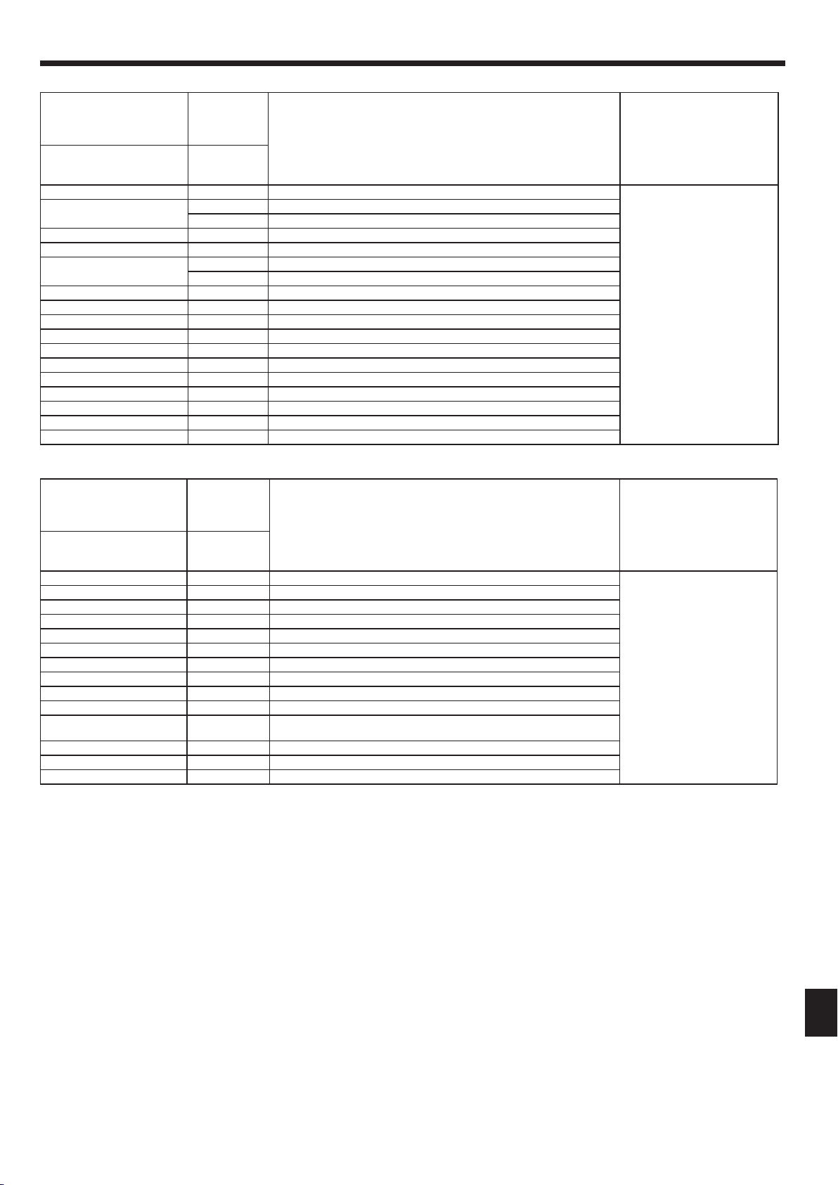
7. Выполнениеиспытания
[ШаблонвыводаA]Ошибки,обнаруженныевнутреннимприбором
беспроводногопультадис-
танционногоуправления
Звучитсигнал/мигает
РАБОЧИЙСВЕТОВОЙИНДИ-
КАТОР(Числораз)
1 P1 Ошибкавпускногодатчика
2
3 E6,E7 Ошибкасвязимеждувнутренним/наружнымприбором
4 P4 Ошибкадренажногодатчика/
5
6 P6 Работаврежимезащитыотобледенения/перегрева
7 EE Ошибкасвязимеждувнутренниминаружнымприборами
8 P8 Ошибкатемпературытрубы
9 E4 Ошибкаполучениясигналапультадистанционногоуправления
10 — —
11 Pb Ошибкамоторавентиляторавнутреннегоблока
12 Fb
14 PL Ненадлежащеефункционированиеконтурахладагента
Нетзвука E0,E3 Ошибкапередачипультадистанционногоуправления
Нетзвука E1,E2 Ошибкаплатыуправленияпультадистанционногоуправления
Нетзвука –––– Несоответствует
Проводного
пультадис-
танционного
управления
Кодпроверки
P2 Ошибкадатчикатрубы(TH2)
P9 Ошибкадатчикатрубы(TH5)
P5 Ошибкадренажногонасоса
PA Ошибкапринудительногокомпрессора
Ошибкасистемыуправлениявнутреннимприбором(ошибкапамятиит.д.)
Признак Примечание
Разъемпоплавковоговыключателяразомкнут
[ШаблонвыводаB]Ошибки,обнаруженныеприбором,кромевнутреннегоприбора(наружныйприборит.д.)
беспроводногопультадис-
танционногоуправления
Звучитсигнал/мигаетРАБО-
ЧИЙСВЕТОВОЙИНДИКА-
ТОР(Числораз)
1 E9
2 UP Прерываниекомпрессорапоперегрузкепотоку
3 U3,U4 Размыкание/короткоезамыканиетермисторовнаружногоприбора
4 UF
5 U2
6 U1,Ud
7 U5 Ненормальнаятемпературатеплоотвода
8 U8 Аварийныйостановвентиляторанаружногоприбора
9 U6
10 U7
11 U9,UH
12 — —
13 — —
14 Прочее Другиеошибки(См.техническоеруководствонаружногоприбора.)
*1ЕслизвуковойсигналнепрозвучитсновапослепервоначальныхдвухсигналовподтвержденияприемасигналадлязапускасамопроверкииРАБОЧИЙСВЕТО-
ВОЙИНДИКАТОРнезагорится,записейобошибкахнет.
*2Еслизвуковойсигналпрозвучиттриразаподряд“бип,бип,бип(0,4+0,4+0,4сек.)”послепервоначальныхдвухсигналовподтвержденияприемасигналадля
запускасамопроверки,указанныйадресхладагентанеправильный.
• Набеспроводномпультедистанционногоуправления
Непрерывныезвонкизуммерасобластиприемасигналовнавнутреннемприборе.
Миганиелампочкиработы
• Напроводномпультедистанционногоуправления
Проверьтекод,отображенныйнаЖК-дисплее.
Проводного
пультадис-
танционного
управления
Кодпроверки
Признак Примечание
Ошибкасвязивнутреннего/наружногоприбора(Ошибкапередачи)(Наружныйприбор)
Прерываниекомпрессорапоперегрузкепотоку(Когдакомпрессорзаблокирован)
Ненормальновысокаятемпературанагнетания/49Cсработало/недостаточнохладагента
Ненормальновысокоедавление(63Hсработало)/Работаврежимезащитыотперегрева
Прерываниекомпрессорапоперегрузкепотоку/Неисправностьвмодулеэлектропитания
Ненормальновысокоетеплоойлричинени3койтемлературынагнетания
Неисправность,например,перенапряжениеилинедостатокнапряженияин
енормальныйсинхронныйсигналкглавнойцепи/Ошибкадатчикатока
Подробнеесм.ЖК-дисплей
платынаружногоконтроллера.
225
Page 36
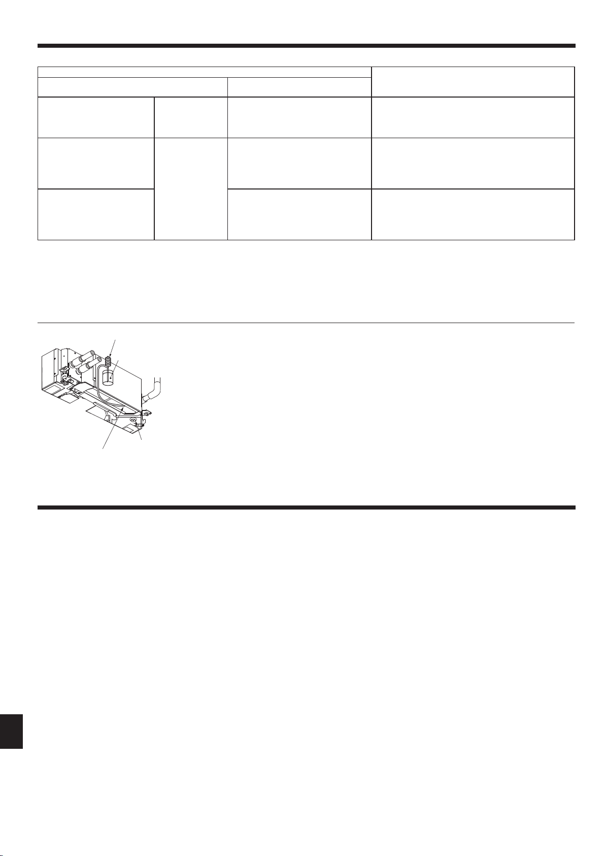
7. Выполнениеиспытания
• Еслиприборнеработаетдолжнымобразомпослепроведенияпробногопрогона,устранитенеисправность,обратившиськнижеприведеннойтаблице.
Симптом
Проводнойпультдистанционногоуправления
Втечениеприбли-
PLEASEWAIT(Ждите)
PLEASEWAIT(Ждите)→Код
ошибки
Сообщенияобошибкахневыводятсянадисплей,дажеесли
выключательработынаходится
вположенииON
(негоритлампочкаработы).
Ввышеописанномсостояниибеспроводногопультадистанционногоуправлениянаблюдаютсяследующиеявления.
• Сигналыспультадистанционногоуправлениянепринимаются.
• Мигаетлампочка
• Зуммериздаеткороткийвысокийгудок.
Примечание:
Втечениеприблизительно30секундпослеотменывыборафункцииуправлениеневозможно.(Правильнаяработа)
ОписаниекаждогоСИДа(СИД1,2,3),предусмотренногонаконтроллеревнутреннегоблока,см.страницу224.
(Вкл.)
работы
.
зительно3минут
послевключения
питания.
Поистечении
приблизительно
3минутпослевключенияпитания.
СИД1,2(печатнаяплатананаружном
приборе)
ПослезагоранияСИД1,2,СИД2выключается,гориттолькоСИД1.
(Правильнаяработа)
ГориттолькоСИД1.→СИД1,2мигают.
ГориттолькоСИД1.→СИД1мигает
дважды,СИД2мигаетодинраз.
•Втечениеприблизительно3минут послевключенияпитания работа пульта дистанционного управления невозможнавследствиезапускасистемы.(Правильнаяработа)
•Неподсоединенсоединительзащитногоустройстванаружногоприбора.
Обратное подсоединениефаз илинеполнофазный режим
электропроводкинаблокетерминаловпитаниянаружного
прибора(L1,L2,L3).
Неправильнаяэлектропроводкамеждувнутренниминаруж-
•
нымприборами(неправильнаяполярностьS1,S2,S3)
•Короткое замыкание провода пульта дистанционного
управления
Причина
A
B
AНасосподачиводы
BВода(около1000куб.см)
CДренажнаяпробка
DЗаливнаягорловинаводы
•Недопускайтепроливаводына
механизмдренажногонасоса.
C
D
Fig.7-5
8. Управлениесистемой
Смотритеруководствопоустановкенаружногоприбора.
7.4. Проверкадренажа(Fig.7-5)
• Убедитесь,чтоводадренируетсяправильно,ичтовместахсоединенийнет
течи.
Послезавершенияэлектрическихработ.
Залейтеводуприработекондиционераврежимеохлаждениявовремяпроб-
•
ногопрогона(см.7.2.)ивыполнитепроверку.
Дозавершенияэлектрическихработ.
Залейтеводуприработекондиционерававарийномрежимеивыполнитепроверку
•
*Дренажныйподдонивентиляторвключаютсяодновременно,когдаоднофаз-
ное напряжение220–240Вподается на S1 иS2клеммнойколодкипосле
включения соединителя (SWE) на плате контроллера распределительного
щита.
Послевыполненияработпереведитееговисходноеположение.
.
226
Page 37
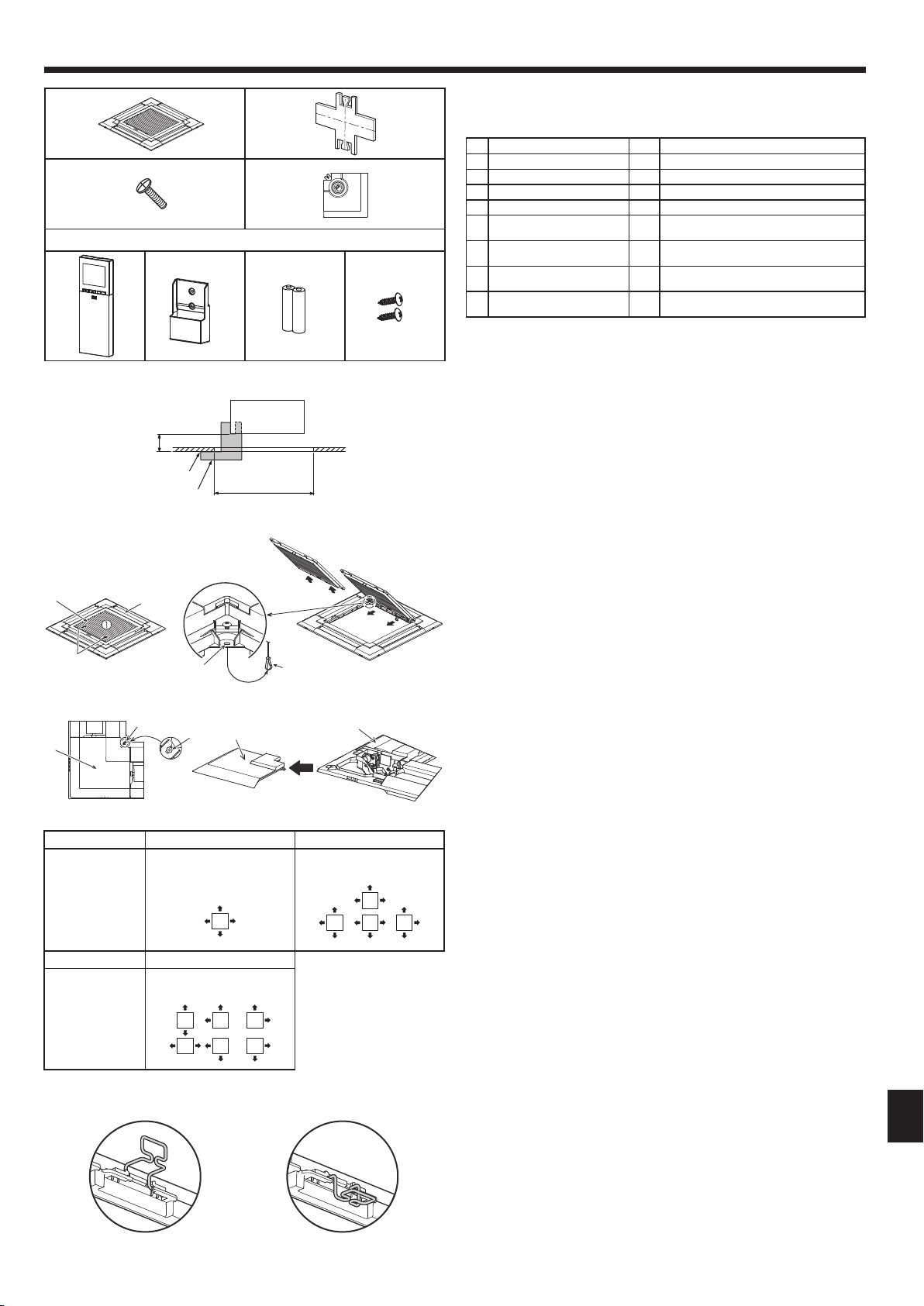
9. Установкавентиляционнойрешетки
1 2
3 4
Приналичиибеспроводногопультадистанционногоуправления
5 6 7 8
Fig.9-1
+5
0
A=17
B
C
A
D
Fig.9-2
9.1. Проверкасодержимогокомплекта(Fig.9-1)
• Вданномкомплектеимеетсянастоящееруководствоинижеперечисленные
части.
Названиеприспособления
Решетка 1 950×950(мм)
1
Монтажныйкалибр 1 (Поделенна4части)
2
Винт(4×16) 1 дияPLP-6EAE,PLP-6EALE,PLP-6EALME
3
Угловаяпанельi-seesensor 1 дияPLP-6EAE,PLP-6EALE,PLP-6EALME
4
Беспроводнойпультдистан-
5
ционногоуправления
Держательпультадистанци-
6
онногоуправления
БатарейкиLR6AA 2
7
Шурупы-саморезы3,5x16 2
8
9.2.
Подготовкакустановкевентиляционнойрешетки
Количество
1 дияPLP-6EALM,PLP-6EALME
Входитвкомплектприналичиибеспровод-
1
ногопультадистанционногоуправления.
Входитвкомплектприналичиибеспровод-
ногопультадистанционногоуправления.
Входитвкомплектприналичиибеспровод-
ногопультадистанционногоуправления.
Замечание
(Fig.9-2)
• Спомощьюпоставляемоговданномкомплектекалибра2отрегулируйте
ипроверьтеразмещениеглавногоприбораотносительноповерхностипотолка.Еслиположениеглавногоприбораотносительноповерхностипотолка
неправильное,торезультатоммогутявитьсяутечкивоздухаилиобразованиеконденсата.
• Убедитесьвтом,чтоотверстиевпотолкеимеетследующиедопустимые
размеры:860×860-910×910
• Убедитесьвтом,чтооперацияАвыполняетсявпределах17-22мм.Несоблюдениеданногопределаможетврезультатепривестикповреждениям.
AГлавныйприбор
BПоверхностьпотолка
CМонтажныйкалибр2(вставленвглавныйприбор)
DГабаритыпотолочногоотверстия
A
C
F
Шаблонынаправ-
ленийвыдува
Шаблонынаправ-
ленийвыдува
B
E
Fig.9-3
G
H
G
F
Fig.9-4
4направления 3направления
1шаблон:
заводскаяустановка
2направления
6шаблон:
двавоздуховодаполностьюзакрыты
2
2
D
B
1
4шаблон:
одинвоздуховодполностьюзакрыт
9.2.1. Удалениевоздухозаборнойрешетки(Fig.9-3)
• Сдвиньтерычагивнаправлении, обозначенномстрелкой1,чтобыоткрыть
воздухозаборнуюрешетку.
• Снимитесзащелкикрюк,удерживающийвентиляционнуюрешетку.
*Неснимайтесзащелкикрюквоздухозаборнойрешетки.
• Покавоздухозаборнаярешетканаходитсяв“открытом”положении,удалите
стерженьвоздухозаборнойрешеткисвентиляционнойрешеткивнаправлении
стрелки2.
9.2.2. Удалениеугловойпанели(Fig.9-4)
• Ослабьте4винтанауглу.Сдвиньтеугловуюпанельвнаправлениистрелки1,
показаннойнарисунке,иснимитеее.
[Fig.9-3][Fig.9-4]
AВоздухозаборнаярешетка
BВентиляционнаярешетка1
CРычагивоздухозаборнойрешетки
DКрюквентиляционнойрешетки
EОтверстиедлякрюкавентиляционнойрешетки
FУгловаяпанель
GВинт
HДеталь
9.3.Выборвытяжныхотверстий
Вданнойвентиляционнойрешеткеимеется11образцовнаправлениявыдува.
Крометого,спомощьюнастройкипультадистанционногоуправлениянасоответствующиезначенияВыможетерегулироватьпотоквоздухаиегоскорость.
ВыберитетребуемыеутановкиизТаблица1всоответствиисместомустановки
устройства.(Необходимовыбратьболее2направлений.)
1) Выберитеобразецнаправлениявыдува.
2) Убедитесьвтом,чтопультдистанционногоуправлениянастроеннасоответ-
ствующиеустановкисогласночислувытяжныхотверстийивысотепотолка,
накоторомбудетустановленглавныйприбор.
(См.стр.222.)
Таблица1
Fig.9-5
Примечание:
• Приизмененииколичестванаправленийнеобходимапластинказаслонки
вытяжногоотверстия,котораяявляетсядетальюподополнительному
<Крючоквнижнемположении><Крючоквподнятомположении>
заказу.
• Невыбирайте2направлениявжаркойивлажнойсреде.(Возможнообразованиеросыиликапель.)
9.4.Установкавентиляционнойрешетки
9.4.1. Подготовка(Fig.9-5)
Убедитесь,чтозацепили2крючказавентиляционнуюрешетку.
227
Page 38
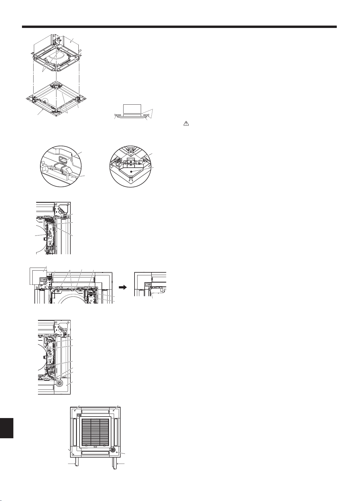
9. Установкавентиляционнойрешетки
A
C
D
F
AГлавныйприбор
BУголдренажнойтрубы
CЗахватнаглавномприборе
B
DВентиляционнаярешетка1
EОтверстиенавентиляционнойрешетке
FКрючокдлявременнойустановки
GВинтспривязнойпрокладкой
HПоверхностьпотолка
JОтсутствиезазора
KОтрегулируйтеположениегайкинаглав-
номприбореспомощьюгаечногоключа
ит.д.
E
H
Fig.9-6
<Временнаяустановкавентиляционнойрешетки>
C
D
Fig.9-7
C
D
B
A
AЗажимглавногоприбора
BРаспределительныйщит
CПроволочныевыводывентиляционной
решетки
DРазъемCNVнаплатеконтроллера
Fig.9-8
A
B
D
C
E
9.4.2.Временнаяустановкавентиляционнойрешетки(Fig.9-6)
• Состыкуйтеуголдренажнойтрубынаглавномприборесугломотверстияна
вентиляционнойрешеткеивременносоединитеих,зацепив крючоквентиляционнойрешеткизазахватглавногоприбора.
9.4.3. Креплениевентиляционнойрешетки
• Закрепите решетку наглавномприборе, затянув заранееустановленные
винты.(Fig.9-6)
Примечание:
Убедитесьвотсутствиизазоровмеждуглавнымприборомивентиляционнойрешеткойилимеждувентиляционнойрешеткойиповерхностью
потолка.(Fig.9-6)
Вслучаезазорамеждувентиляционнойрешеткойипотолком:
A
J
D
G
K
После закреплениявентиляционнойрешетки отрегулируйтеустановочную
высотуглавногоприбораиустранитезазор.
Осторожно:
• Призатягиваниивинтаубедитесь,чтомоментзатяжкивдиапазоне2,83,6н•м.Неиспользуйтепневматическуюотвертку.
• Послезатяжкивинта убедитесь,что двакрючкарешетки(Fig.9-7) зафиксированынакрючкахнаосновномблоке.
9.4.4. Соединениепроводов(Fig.9-8)
• Выкрутите2винтакреплениякрышкираспределительногощитанаглавном
прибореисдвиньтекрышку,чтобыоткрыть.
• Проложитепроволочныйвыводсостороныраспределительногощита.
• Подсоединитеразъеммоторазаслонок(белогоцвета,20полюсный)кразъему
CNV(белогоцвета)наплатеконтроллераглавногоприбора.
• Проволочныевыводы,отходящиеотрешетки,должныбытьсобранывместе
безпровисанияприпомощизажимаипущенынараспределительныйщит.
9.4.5. Установкаприемникасигналов(Fig.9-9)
• Проложитепроволочныйвывод(белогоцвета,9полюсный)дляугловойпанелиприемникасигналовсостороныраспределительногощитанаглавном
приборе.
• ПодсоединитекразъемуCN90(белогоцвета)наплатеконтроллера.
• Пропуститепроволочныйвыводугловойпанелиприемникасигналовчерез
захватраструба.
• Остаткипроволочноговыводадолжныбытьсобранывместебезпровисания
припомощизажимаипущенынараспределительныйщит.
• 2винтамизакрепитекрышкунараспределительномщите.
Примечание:
Убедитесь,чтопроводанезащемилиськрышкойраспределительногощита.
Установитеугловуюпанельприемникасигналовнапанельизафиксируйте
винтом.
Для главногоприбора нельзя устанавливать угловуюпанельприемника
сигналовнасторонедренажнойтрубы.(См.Fig.9-11)
Недопустимоеполо-
жениеприустановке
Дренажнаятруба
F
G
Fig.9-9
ACN4Zнаплатеконтроллера
B
A
C
E
F
G
BCN5Yнаплатеконтроллера
CПроволочныйвывод угловойпанели
i-seeSensor
DЗажим
EОтверстиевентиляционнойрешетки
(Пропуститьпроволочныйвывод.)
FВинт3
GУгловаяпанельi-seeSensor4
Fig.9-10
Положение1 Положение2
Положение3
Трубадляхладагента
AУгловаяпанельприемникасигналов
BОтверстиевентиляционнойрешетки(Пропуститепроволочныйвывод.)
H
CЗахватраструба
DПровод
EЗажим
FКлямса(Фиксацияпроволочноговывода.)
GCN90наплатеконтроллера
HВинт
9.4.6. Установкаугловойпанелиi-seeSensor(Fig.9-10)
• Проложитепроволочныйвыводсостороныраспределительногощита.
• Проложитеразъемпроволочноговывода(белогоцвета,4полюсныйибелого
цвета,5полюсный)угловойпанелиi-seeSensor4со стороныраспределительногощитанаглавномприбореиподсоединитеразъемCN4ZиCN5Yна
платеконтроллера.
• Остатки проволочноговывода угловойпанелиi-see Sensor должныбыть
собранывместебезпровисанияприпомощизажимаипущенынараспределительныйщит.
• 2винтамизакрепитекрышкунараспределительномщите.
Примечание:
Убедитесь,чтопроводанезащемилиськрышкойраспределительногощита.
• Угловаяпанельi-seeSensorдолжнакрепитьсянавентиляционнуюрешетку
1винтом3.
* Еслиположениеi-seeSensorбылоизмененосположенияпоумолчанию(по-
ложение3)надругоеположение,изменитенастройкифункции.(См.страница
222иFig.9-11)
• Дляглавногоприбораневозможноустановитьугловуюпанельi-seeSensor
насторонедренажнойтрубы.(См.Fig.9-11)
Положение1: Положениеприемникасигналовпоумолчанию(Идентификаци-
Положение2: (Идентификационныеотметкивыдувныхотверстий□/□□)
Положение3: Положениеi-see Sensor по умолчанию(Идентификационные
онныеотметкивыдувныхотверстий□/□□□□)
отметкивыдувныхотверстий□□/□□□)
228
Fig.9-11
Page 39
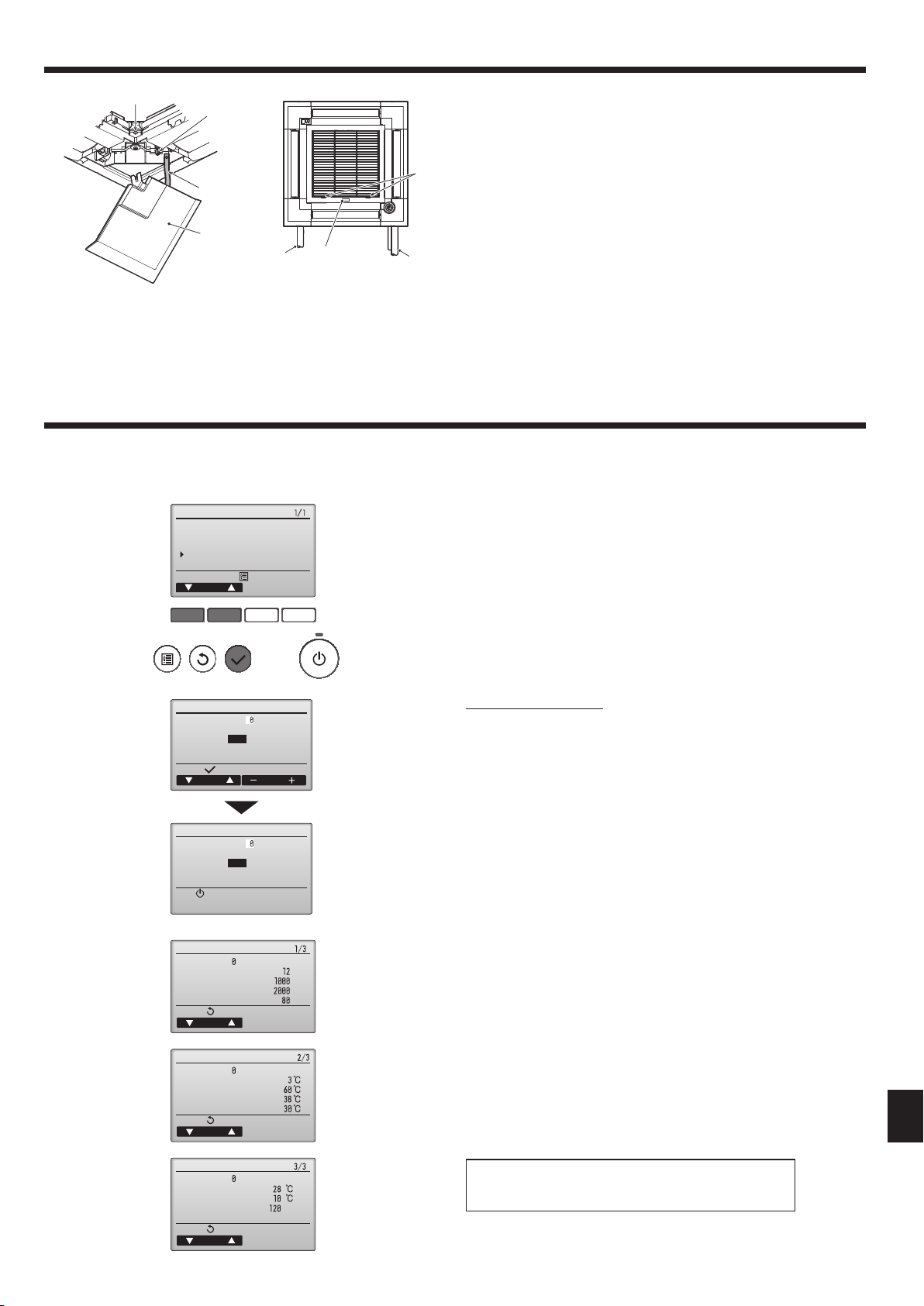
9. Установкавентиляционнойрешетки
A
D
H
C
B
G
F
E
Fig.9-12
9.5. Установкавоздухозаборнойрешетки(Fig.9-12)
Примечание:
Приустановкенаместоугловыхпанелей(каждаясприкрепленнымпредохранительнымпроводом)присоединитевторойконецпредохранительного
проводаквентиляционнойрешетке,какпоказанонаиллюстрации.
* Еслинезакрепитьугловыепанели,онимогутупастьвовремяработыглавного
прибора.
•
Выполнитешаги,описанныевп.“9.2.Подготовкакустановкевентиляционной
решетки”,в обратномпорядке, чтобыустановитьвоздухозаборнуюрешеткуи
угловуюпанель.
• Пользовательможет изменять направлениевоздухозаборной решеткипо
своемужеланию.
AВинт(4×16)
BУгловаяпанель
C
Предохранительныйпровод
D
Крючок
EТрубахладагента
FДренажнаятруба
G
логотипКомпании
*Возможнаустановкавлюбомположении.
HИсходноеположениерычаговнавоздухозаборнойрешетке
*
Хотязажимыможноустанавливатьвлюбомиз4положений,рекомендуется
конфигурация,показаннаянарисунке.
хозаборнуюрешеткуприпроведениитехобслуживанияраспределительного
щитанаглавномприборе.)
(нетнеобходимостисниматьвозду-
10. Функцияпростоготехобслуживания
Данныеобслуживания,такиекактемпературатеплообменникавнутреннего/наружногоблоковирабочийтоккомпрессора,могутотображатьсяспомощьюфункции
“Smoothmaintenance”(Плавноеобслуживание).
* Выполнениеэтойфункцииневозможнововремяпроведенияиспытаний.
* Взависимостиоткомбинацииснаружнымприборомнанекоторыхмоделяхэтафункцияможетнеподдерживаться.
1
Error history
Refrigerant volume check
Refrigerant leak check
Smooth maintenance
Request code
Service menu:
Cursor
Check menu
• ВыберитевMainmenu(главномменю)пункт“Service”(Сервисноеобслуживание)инажмитекнопку[ВЫБОР].
• С помощьюкнопки[F1]или[F2] выберитепункт“Check” (Пров.)и нажмите
кнопку[ВЫБОР].
• Спомощьюкнопки[F1]или[F2]выберитепункт“Smoothmaintenance”(Плавное
обслуживание)инажмитекнопку[ВЫБОР].
F1 F2 F3 F4
2
3
Smooth maintenance
Ref.address
Stable mode
Cool / Heat/ Normal
Begin:
Cursor
Smooth maintenance
Ref.address
Stable mode
Cool / Heat/ Normal
Stabilization→Collecting
Exit:
Smooth maintenance
Ref. address
COMP. current
COMP. run time
COMP. On / Off
COMP. frequency
Return:
Page
Smooth maintenance
Ref.address
Sub cool
OU TH4 temp.
OU TH6 temp.
OU TH7 temp.
Return:
Page
Cool
Cool
Address
A
Hr
times
Hz
Выберитенужныйэлемент
• Кнопкой[F1]или[F2]выберитеэлемент,которыйнеобходимоизменить.
• Кнопкой[F3]или[F4]выберитенужныйпараметр.
Параметр“Ref.address”(Адресобращ.)………..“0” - “15”
Параметр“Stablemode”(Стабильныйрежим)
………..“Cool”(Охлажд.)/
“Heat”(Нагрев)/
“Normal”(Нормальный)
• Нажмитекнопку[ВЫБОР],начнетсяработаввыбранномрежиме.
* Работаврежиме“Stablemode”(Стабильныйрежим)займетприм.20минут.
Отобразятсярабочиеданные.
Дляпараметраобщеговремени работы компрессора (COMP.run(КОМП.
раб.))используетсяединица10часов,адляпараметраколичествавключений
компрессора(COMP.On/Off(КОМП.Вкл/Выкл))используетсяединица100раз
(дробныезначенияисключены)
Smooth maintenance
Ref.address
IU air temp.
IU HEX temp.
IU filter time
Return:
Page
Cool
Навигацияпоэкранам
• ДлявозвратавГлавноеменю ............. кнопка[МЕНЮ]
Длявозвратакпредыдущемуэкрану
Hr
•
......... кнопка[ВОЗВРАТ]
229
Page 40
This product is designed and intended for use in the residential,
commercial and light-industrial environment.
Please be sure to put the contact address/telephone number on
this manual before handing it to the customer.
Не забудьте указать контактный адрес/номер телефона в данном
руководстве, прежде чем передать его клиенту.
HEAD OFFICE: TOKYO BUILDING, 2-7-3, MARUNOUCHI, CHIYODA-KU, TOKYO 100-8310, JAPAN
Название Компании: ООО «Мицубиси Электрик (РУС)»
Адрес: 115114, Российская Федерация, г. Москва, ул. Летниковская, д. 2, стр. 1, 5 этаж
GG79D015H01 Printed in UNITED KINGDOM
 Loading...