

Page 1
TECHNICAL & SERVICE MANUAL
SPLIT-TYPE, AIR CONDITIONERS
CONTENTS
1. TECHNICAL CHANGE ·························3
2. SPECIFICATIONS·································4
3. DATA·····················································6
4.
REFRIGERANT SYSTEM DIAGRAM
········7
5. PARTS LIST··········································8
Indoor unit
[Model name]
No. OC203
This service manual describes
only the change points.
Please refer to No.OC151
REVISED EDITION-A as to
excluding this manual.
This manual does not cover the
following outdoor units.
When serving them, please refer
to the service manual No.OC149
REVISED EDITION-B , OC202
and this manual in a set.
[Service Ref.]
PU-3VJC
.UK (OC202)
PU-3YJC.UK (OC202)
PU-3NJA1.UK (OC149 REVISED EDITION-B)
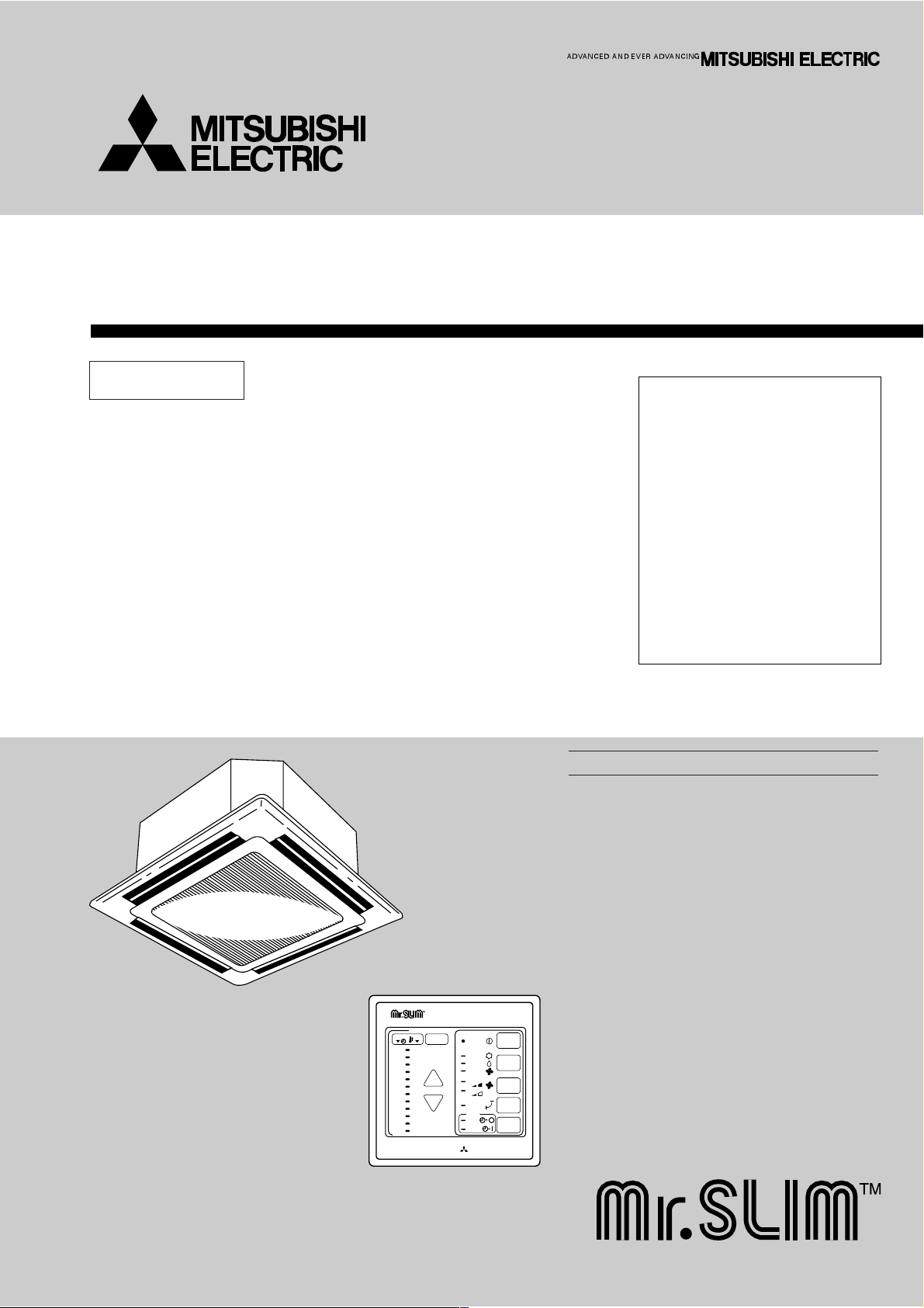
INDOOR UNIT
Ceiling Cassettes
Series PL
MITSUBISHI ELECTRIC
12
11
10
9
8
7
6
5
4
3
2
1
29
28
27
26
25
24
23
22
21
20
19
18
TIMER TEMP
TIMER/TEMP.
UP
DOWN
POWER
COOL
ON/OFF
LOUVER
MODE
SELECT
FAN
SPEED
TIMER
MODE
DRY
FAN
HIGH
LOW
ON
AUTO
STOP
START
REMOTE CONTROLLER
[Service Ref.]
PL-3GJB
PL-3GJB2.UK
Page 2

Page 3

3
TECHNICAL CHANGE
1
Difference between the connection with PL-3GJB1.UK.
CHANGE POINTS
PL-3GJB
1.UK
PL-3GJB
2.UK
COOLING CAPACITY
OUT DOOR UNIT
25,200 BTU/h
7,400 W
PU-3VJA
2.UK
PU-3YJA
2.UK
27,000 BTU/h
7,900 W
PU-3VJC.UK
PU-3YJC.UK
Page 4
2 SPECIFICATIONS
1. STANDARD SPECIFICATIONS
Item
Cooling capacity w1
Cooling capacity (SSA) w2
Total input (50/60Hz) w3
Service Ref.
External finish
Fan motor output
Airflow Hi-Lo
External static pressure
Operation control &Thermostat
Indoor unitOutdoor unit Indoor grill
Noise level high-Low
Unit drain pipe I.D.
Dimensions
Weight
External finish
Dimensions
Weight
Service Ref.
External finish
Refrigerant (R-22) control
Crankcase heater w4
Compressor output
Protection devices
Fan motor output
Airflow
Noise level
Dimensions
Weight
50Hz
60Hz
60Hz
50Hz
60Hz
50Hz
60Hz
H
W
D
H
W
D
50/60Hz
50/60Hz
50Hz
60Hz
50/60Hz
W
D
H
Service Ref.
W
Btu/h
W
Btu/h
W
Btu/h
kW
kW
3
/ min
m
CFM
3
/ min
m
CFM
Pa(mmAq)
dB
dB
mm(in.)
mm(in.)
mm(in.)
mm(in.)
kg(lbs)
mm(in.)
mm(in.)
mm(in.)
kg(lbs)
W
kW
kW
3
/ min(CFM)
m
3
/ min(CFM)
m
dB
mm(in.)
mm(in.)
mm(in.)
kg(lbs)
Galvanized sheets with gray heat insulation
PU-3VJC.UK, PU-3YJC.UK, PU-3NJA
PL-3GJB
PL-3GJB
0(Direct blow)
Remote control & Built-in
Munsell 0.70Y 8.59/0.97
Munsell 5Y 7/1
Capillary tube
295+24(11-5/8+1)
2.UK
7,900
27,000
8,000
27,300
6,900
23,500
3.34/3.60
2.UK
0.05
18-14
635-494
18-14
635-494
39-32
39-32
32(1-1/4)
258(10-3/16)
820(32-1/4)
820(32-1/4)
28(62)
65(2-9/16)
950(37-3/8)
950(37-3/8)
7(16)
32/38
2.2 , 2.4 / 2.2
w5
0.085
50(1765)
50(1765)
52/53
870(34-1/4)
850(33-7/16)
73(161)
1.UK
Notes :
w1 Rating conditions (JIS B8616) w4 Capacity of crankcase heater (W) based on 220 volts.
Indoor : D.B. 27°C (80°F), W.B. 19°C (66°F) w5 V, N···Inner thermostat, HP switch, LP switch.
Outdoor : D.B. 35°C (95°F), W.B. 24°C (75°F) Y ·······Thermal switch, Reversed-phase protector, HP switch, LP switch,
Refrigerant piping length (one way) : 5m (16ft) Thermal relay
w2 Rating conditions (SSA 385, 386)
Indoor : D.B. 29°C (84°F), W.B. 19°C (66°F)
Outdoor : D.B. 46°C (115°F), W.B. 24°C (75°F)
Refrigerant piping length (one way) : 5m (16ft)
w3 Total input based on indicated voltage
(Indoor / Outdoor)
Service Ref.
50Hz
60Hz
PL-3GJB
1ph 220V/1ph 220V , 3ph 380V
1ph 220V/1ph 220V
2.UK
4
Page 5

5
2. POWER SUPPLY & MODEL NAMES
Notes : 1. Power supply key N
.......
1ph, 220V,60Hz
V
........
1ph, 220, 230, 240V, 50Hz , Y
...
3ph. 380/220, 400/230, 415/240V , 50Hz, 4 wires
2. Primary power supplies for all indoor units are single-phase.
3. ELECTRICAL SPECIFICATIONS
Rating conditions -JIS B 8616
{
Indoor : D.B. 27°C (80°F), W.B.19°C (66°F)
Outdoor : D.B. 35°C (95°F), W.B.24°C (75°F)
Power supply
50Hz
1ph.
60Hz
3ph.
1ph.
3ph.
Indoor unit Service Ref. : PL-3GJB
2.UK
Outdoor unit Service Ref.
220, 230, 240V
380/220, 400/230, 415/240V
220V
220V
PU-3VJC.UK
PU-3YJC.UK
PU-3NJA
1.UK
—
Power supply (1 Phase)
V : 220V 50Hz
Service Ref. : PL-3GJB
2.UK
Current A
Outdoor unit
Input
Starting current
kW
A
0.72
0.16
1.0
PU-3
V : 230V 50Hz
0.72
0.16
1.0
PU-3
V : 240V 50Hz
0.72
0.16
1.0
PU-3
0.72
0.16
1.0
PU-3
N,T : 220V 60Hz
-
SSA 385, 386
{
Indoor : D.B. 29°C (84°F), W.B. 19°C (66°F)
Outdoor : D.B. 46°C (115°F), W.B. 24°C (75°F)
Page 6

3
DATA
1.COOLING CAPACITY CORRECTION FACTORS 50Hz
Service Ref.
PL-3GJB
2.UK
5m (16ft)
1.0
10m (33ft)
0.978
15m (49ft)
0.962
Refrigerant piping length (one way)
20m (66ft)
0.948
25m (82ft)
0.934
30m (98ft)
0.921
35m (115ft)—40m (131ft)—45m (148ft)—50m (164ft)
2.STANDARD OPERATION DATA
Service Ref.
MODE
Capacity
Total
Input
W
kW
Indoor unit service Ref.
Phase , Hz
Volts
Amperes
V
A
Outdoor unit service Ref.
Electrical circuit
Phase , Hz
Volts
Amperes
Discharge pressure
Suction pressure
Discharge temperature
Condensing temperature
Suction temperature
Refrigerant circuit
Ref. pipe length
Intake air temperature
Discharge air temperature
Indoor side
Intake air temperature
side
Outdoor
D.B.
W.B.
D.B.
D.B.
W.B.
V
A
MPa
(kgf/cm2)
MPa
(kgf/cm2)
°C
°C
°C
m
°C
°C
°C
°C
°C
The unit of pressure has been changed to MPa based on SI (International System of unit) in
accordance with I.S.O.(International Organization for Standardization).
The conversion factor is : 1(MPa) = 10.2(kgf/cm
PL-3GJB2.UK
Cooling
7,900
3.34
PL-3GJB2.UK
1 , 50
220
0.72
PU-3VJC.UK
1 , 50
220
15.1
1.88
(19.2)
0.46
(4.7)
87
51
5
5
27
19
12.3
35
24
2
)
Cooling
8,000
3.60
1 , 60
220
0.72
PU-3NJA1.UK
1 , 60
220
17.6
2.02
(20.6)
0.43
(4.4)
72
53
3
5
27
19
12.3
35
24
—
3.ADDITIONAL REFRIGERANT CHARGE (R-22 : kg(lbs))
Service Ref.
PL-3GJB
2
.UK
Outdoor unit precharged (kg)
(up to 20)
V…2.8,Y…2.8,N…3.5 0.06(0.13) 0.12(0.26) — — —
20m(66ft)
0
25m(82ft) 30m(98ft) 35m(115ft) 40m(131ft) 45m(148ft)—50m(164ft)
Piping length(one way)
6
Page 7

REFRIGERANT SYSTEM DIAGRAM4
PL-3GJB2.UK / PU-3VJC.UK, PU-3YJC.UK, PU-3NJA1.UK
Refrigerant pipe ø15.88(5/8")
Indoor heat
exchanger
strainer
Indoor coil
thermistor
RT2
Distributor
with
strainer
Refrigerant pipe ø9.52(3/8")
(with heat insulator) option
(with insulator) option
Flexible tube
Flared
connection
Flexible tube
Flared
connection
strainer
Low pressure
switch
Ball
valve
Ball valve
(with service port)
Charge
pIug
Accumulator
[O.D.3.2 oI.D.1.8 o800]
o2pcs
High pressure
switch
Check
pIug
strainer
Compressor
Capillary tube
D.P.R.
(Discharge pressure regulator)
Unit : mm(inch)
Outdoor heat
exchanger
flow of refrigerant
7
Page 8

8
5
PARTS LIST
No.1Part No. Part Name Specifications
Remarks
(Drawing No.)
Wiring
Diagram
Symbol
Q'ty/set Price
Unit
PL-3
GJB.UK, GJB1.UK
GJB
2
.UK
Recommended
Q'ty
Amount
2
3
4
5
6
7
8
9
10
S70 700 003
S70 W28 500
S70 W28 691
S70 W28 098
S70 20K 200
S70 139 305
S70 W28 054
S70 029 054
S70 W28 083
S70 W28 673
AIR OUTLET GRILLE
AIR FILTER
INTAKE GRILLE
HANGER G
REMOTE CONTROLLER
REMOTE CONTROLLER CABLE
GRILLE CATCH
FILTER CATCH
SHUTTER PLATE
PANEL SCREW
1
1
1
1
1
1
2
2
1
1
R.B
10m
Part numbers that are circled are not shown in the figure.
7
7
8
1
2
3
5
6
4
PANEL PARTS
PL-3GJB.UK
PL-3GJB
1.UK
PL-3GJB
2.UK
Page 9

9
No. Part No. Part Name Specifications
Remarks
(Drawing No.)
Wiring
Diagram
Symbol
Q'ty/set Price
Unit
PL-3
GJB.UK,GJB1.UK
GJB
2
.UK
Recom-
mended
Q'ty
Amount
1
2
3
4
5
6
7
8
9
S70 W29 002
S70 W30 002
S70 W28 085
S70 W28 086
S70 W28 087
S70 W28 088
S70 700 223
S70 W28 063
S70 W28 064
AUTO VANE
AUTO VANE
AIR GUIDE
AIR GUIDE
AIR GUIDE
AIR GUIDE
VANE MOTOR
VANE JOINT
VANE BUSHING
2
2
1
1
1
1
2
4
8
MV
PANEL PARTS
PL-3GJB.UK
PL-3GJB
1 .UK
PL-3GJB
2 .UK
9
8
7
2
9
8
9
9
1
8
5
3
8
6
2
4
9
9
9
Page 10

10
31
23
22
20
19
21
18
17
14
16
15
26
30
25
29
13
12
11
10
9
28
7
2
8
4
8
5
1
3
6
8
27
FUNCTIONAL PARTS
PL-3GJB.UK
PL-3GJB
1.UK
PL-3GJB
2.UK
Page 11

Part numbers that is circled is not shown in the figure.
No.1Part No. Part Name
S70 001 687
2
S70 001 688
3
S70 002 688
4
S70 703 762
5
S70 W28 105
6
S70 W46 130
7
S70 W47 114
8
S70 001 133
9
S70 175 480
10
S70 13B 202
11
S70 K01 523
12
S70 11K 355
13
S70 W28 266
14
S70 020 529
15
S70 522 716
16
S70 512 716
17
S70 11K 799
18
S70 W28 255
19
S70 27K 310
20
S70 001 239
21
S70 001 311
22
S70 001 502
23
S70 13A 202
24
S70 W28 527
25
S70 001 501
26
S70 002 501
27
S70 022 304
28
S70 09K 097
29
S70 006 533
30
S70 A48 524
31
S70 11K 675
BASE
DRUM (1)
DRUM (2)
FAN MOTOR
RUBBER MOUNT
MOTOR LEG
TURBO FAN
LEG
HEAT EXCHANGER
INDOOR COIL THERMISTOR (H)
DRAIN SOCKET
DRAIN PUMP
DRAIN SENSOR
DRAIN PAN
TERMINAL BLOCK
TERMINAL BLOCK
TRANSFORMER
FAN MOTOR CAPACITOR
INDOOR CONTROLLER BOARD
FUSE
INDOOR CONTROLLER CASE
BELL MOUTH
ROOM TEMPERATURE THERMISTOR (S)
DRAIN HOSE
CONTROL BOX T/B ASSY
CONTROL BOX K ASSY
CABLE FOR BOARD
SPL WASHER
SENSOR HOLDER
DRAIN PLUG
FAN GUARD
Specifications
PM6V50-LA
(L, N, ;)
(1, 2)
3µF 400V
250V 6.3A
5m
Q'ty/set Price
PL-3
GJB.UK, GJB1.UK
GJB
2
.UK
1
1
1
1
3
1
1
4
1
1
1
1
1
1
1
1
1
1
1
1
1
1
1
1
1
1
1
1
1
1
1
Remarks
(Drawing No.)
(PART OF THE BOARD)
Wiring
Recom-
Diagram
mended
Symbol
MF1
RT2
DP
DS
TB2
TB4
T
C1
I.B
F1, 2<I.B>
RT1
Q'ty
Unit
Amount
11
Page 12

© Copyright 1999 MITSUBISHI ELECTRIC ENGINEERING CO.,LTD.
Issued in Dec. 1999. No.OC203 242
Printed in Japan
New publication, effective Dec. 1999
Specifications subject to change without notice
TM
HEAD OFFICE MITSUBISHI DENKI BLDG. MARUNOUCHI TOKYO 100-8310 TELEX J24532 CABLE MELCO TOKYO
 Loading...