

Page 1
TECHNICAL & SERVICE MANUAL
SPLIT-TYPE, AIR CONDITIONERS
CONTENTS
1. FEATURES ···········································2
2. PART NAMES AND FUNCTIONS········3
3. SPECIFICATIONS·································5
4. DATA·····················································7
5. OUTLINES AND DIMENSIONS··········10
6. WIRING DIAGRAM·····························12
7.
REFRIGERANT SYSTEM DIAGRAM
······13
8. OPERATION FLOW-CHART··············14
9. MICROPROCESSOR CONTROL·······17
10. TROUBLESHOOTING ························25
11. 4-WAY AIR FLOW SYSTEM ···············27
12. DISASSEMBLY PROCEDURE···········28
13. PARTS LIST········································31
14. OPTIONAL PARTS·····························35
Indoor unit
[Model names] [Service Ref.]
PL-1.6KJC PL-1.6KJC
PL-2KJC PL-2KJC
PL-2.5KJC PL-2.5KJC
No. OC125
1997
This manual does not cover the
following outdoor units. When
serving them, please refer to the
service manual No.OC127 and
this manual in a set.
<Service Ref.>
PU-1.6VLJA
2
PU-2VJA2
PU-2NJA1
PU-2.5VJA2
PU-2.5NJA1
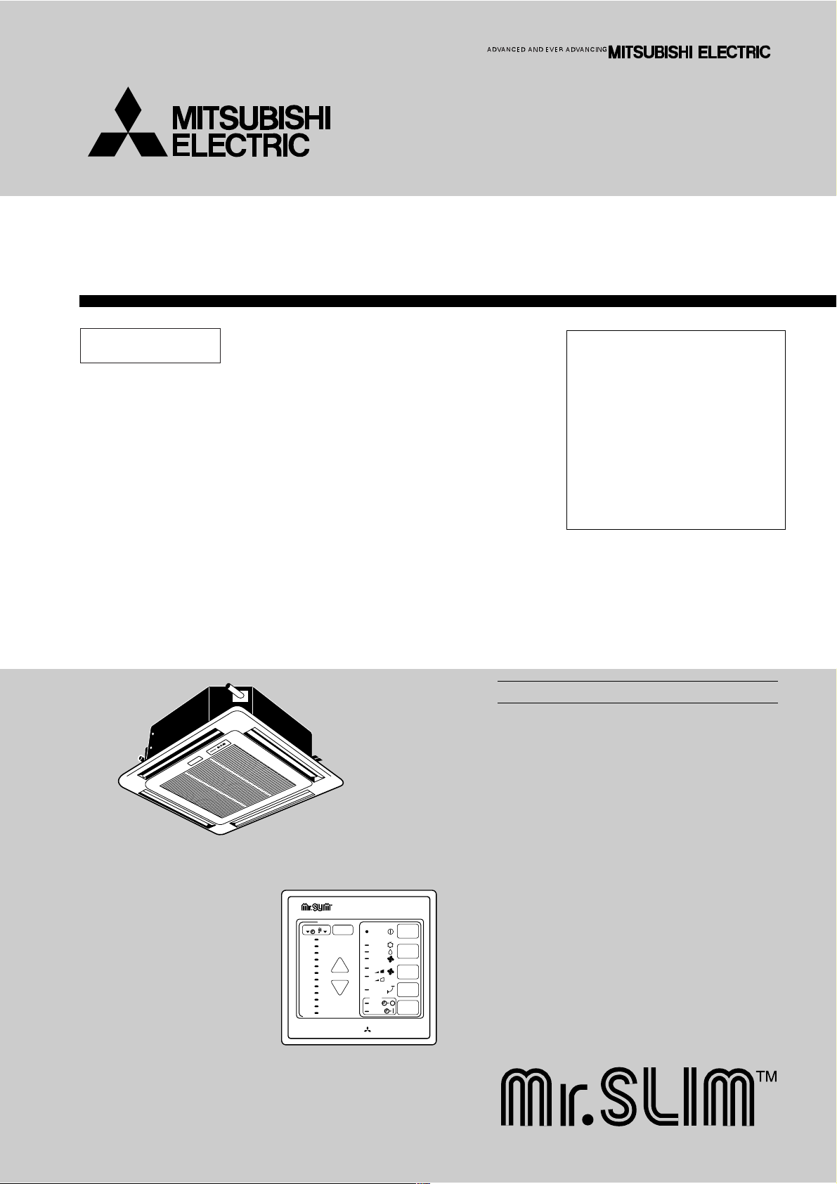
INDOOR UNIT
Ceiling Cassettes
Series PL
MITSUBISHI ELECTRIC
12
11
10
9
8
7
6
5
4
3
2
1
29
28
27
26
25
24
23
22
21
20
19
18
TIMER TEMP
TIMER/TEMP.
UP
DOWN
POWER
COOL
ON/OFF
LOUVER
MODE
SELECT
FAN
SPEED
TIMER
MODE
DRY
FAN
HIGH
LOW
ON
AUTO
STOP
START
REMOTE CONTROLLER
The Slim Line.
From Mitsubishi Electric.
Page 2
2
FEATURES
1
1.PURSUING COMPACTNESS
(1)Panel size and body volume reduced to 64% of previous models
The width and depth of the panel have been reduced by 19cm respectively,resulting in a compact model which fits
smaller environments (like shops) perfectly.
(2)Multi-application panels flexibly adapt to installation conditions.
Space panel and Wide panel may be installed on ceilings with shallow depth using the exiting opening .
2."SMUDGE-FREE", PRECISELY TARGETED AIRFLOW SYSTEM
The new control system regulates airflow to prevent smudging. A projection inside the air passage distributes air evenly
over the top and bottom of the vane. Two projections on the air outlet work to prevent cooled air from rising to the
celling, and also to stop outside air being dragged into the cooled air stream.
3.AIRFLOW ADJUSTABLE TO ANY INDOOR ENVIRONMENT
Airflow can be adjusted according to celling height and the number of air outlets. "Wide Zoming Flow" creates an
optimum airflow for any indoor environment.
4.A FURTHER REFINEMENT OF COMFORT WITH NOISE SUPPRESION
The celling 4-way airflow cassette has a special "silent-design". The "2-Tap"system allows a choice between silent and
standard modes according to the height of the cellig. For ordinary residenced which have a low celling, selection of the
silent mode will result in remarkable noise reductions.
5.ECONOMICAL AND EASY MAINTENANCE
(1)Push-open grill
Filter clogging is widely recognized as a cause of reduced perfomance, but up until now it has been troublesome to
clean filters. With the "push-open grill" the fillter can be smoothly opened out at the push of a button, enabling speedy
cleaning.
(2)An unprecedented level of vane-cleaning
The unique airflow system prevents the intake of indoor air. Dewing therefore does not occur, and the vane is flockless.
The resulting level of dirt on the vane due to tobacco smoke, dust, etc. is very light,and can be wiped off easily with a
neutral detergent.
(3)Long-life fillter
This new celling 4-way airflow cassette employs a long life fillter which requires no maintenance for up to 2,500 hours of
operation in general office environments. It adds uo to an ideal blend of comfort and low maintenance.
Service
Ref.
PL-1.6KJC
PL-2KJC
PL-2.5KJC
Cooling capacity (50/60Hz)
W Btu/h
3,800/ –
5,600/5,400
6,500/7,000
13,000/ –
19,100/18,400
22,200/23,900
Ceiling Cassettes
Series PL
INDOOR UNIT REMOTE CONTROLLER
MITSUBISHI ELECTRIC
12
11
10
9
8
7
6
5
4
3
2
1
29
28
27
26
25
24
23
22
21
20
19
18
TIMER TEMP
TIMER/TEMP.
UP
DOWN
POWER
COOL
ON/OFF
LOUVER
MODE
SELECT
FAN
SPEED
TIMER
MODE
DRY
FAN
HIGH
LOW
ON
AUTO
STOP
START
Rating conditions (JIS B8616)
Indoor : 27°C (80°F) DB, 19°C (66°F)WB
Outdoor : 35°C (95°F) DB, 24°C (75°F)WB
Page 3
3
6.COMPACT DIMENSIONS MEAN EASY INSTALLATION
(1)Carefree suspension work with lightweight unit
The new unit weighs in at 20kg (9kg lighter than the previous model) and is easy to handle and install. What's more,
suspension work is facillitated by compact dimensions ensuring a snug fit.
(2)Smooth installation with "one-direction"bolts
Suspension bolts can be fixes consistently from one direction easing suspension work.
(3)Trouble-free fitting work with slender refrigerant piping
Refrigerant piping has been reduced in size, and pipe-curving work at the installation site can now be completed quickly
and economically. In addition, refrigerant and drain piping are set at different corners, which means that flare connections
and drain piping heat insulation work can be smoothly and reliably implemented.
(4)Easy-access terminal and control panels for efficient wiring
When performing wiring work, progress can be checked on the power source terminal and control panels simply by
removing the electrical parts cover. Address setting can also be done easily from beneath at a convenient angle.
(5)"One-push"to provisionally position front panel
Panel weight has been redused from 7kg to 3.7kg. The previous 3-step process for provisionally positioning the panel
has been streamlined, and now a simple "one-push" action at the diagonal corners fixed it into place, resulting in major
time-saving.
2
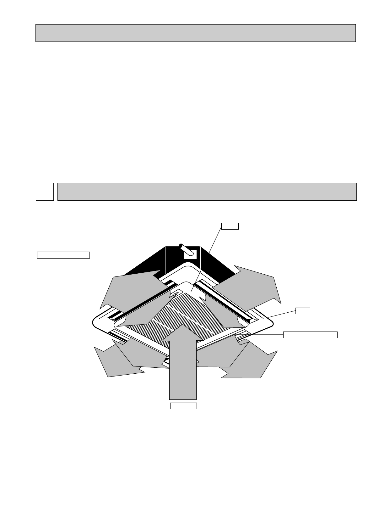
PART NAMES AND FUNCTIONS
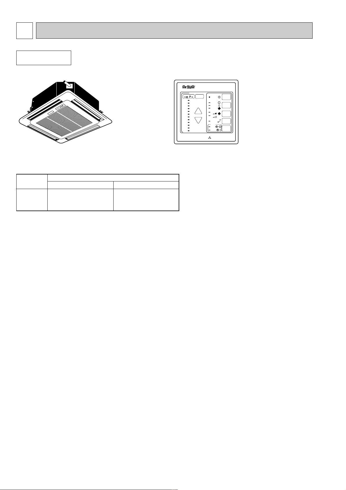
● Indoor Unit
PL-1.6KJC
PL-2KJC
PL-2.5KJC
Auto Air Swing Vane
Disperses airflow up and
down and adjusts the angle
of airflow direction.
Grill
Filters
Remove dust and pollutants
from inhaled air
Horizontal Air Outlet
Sets airflow horizontal automatically
during cooling or dehumidifying.
Air Intake
Inhales air from room.
Page 4
4
Attention
● Pressing the UP and DOWN buttons together for more than two seconds will initiate the “test run” or “self-diagnostic” mode.
Avoid pressing these buttons simultaneously during normal operation. Press the ON/OFF button to cancel test run or selfdiagnostic mode.
●All green lamps turn off when air conditioner is OFF.
●Avoid operation of buttons with fingernails or other sharp objects. Sharp objects may scratch operating panel.
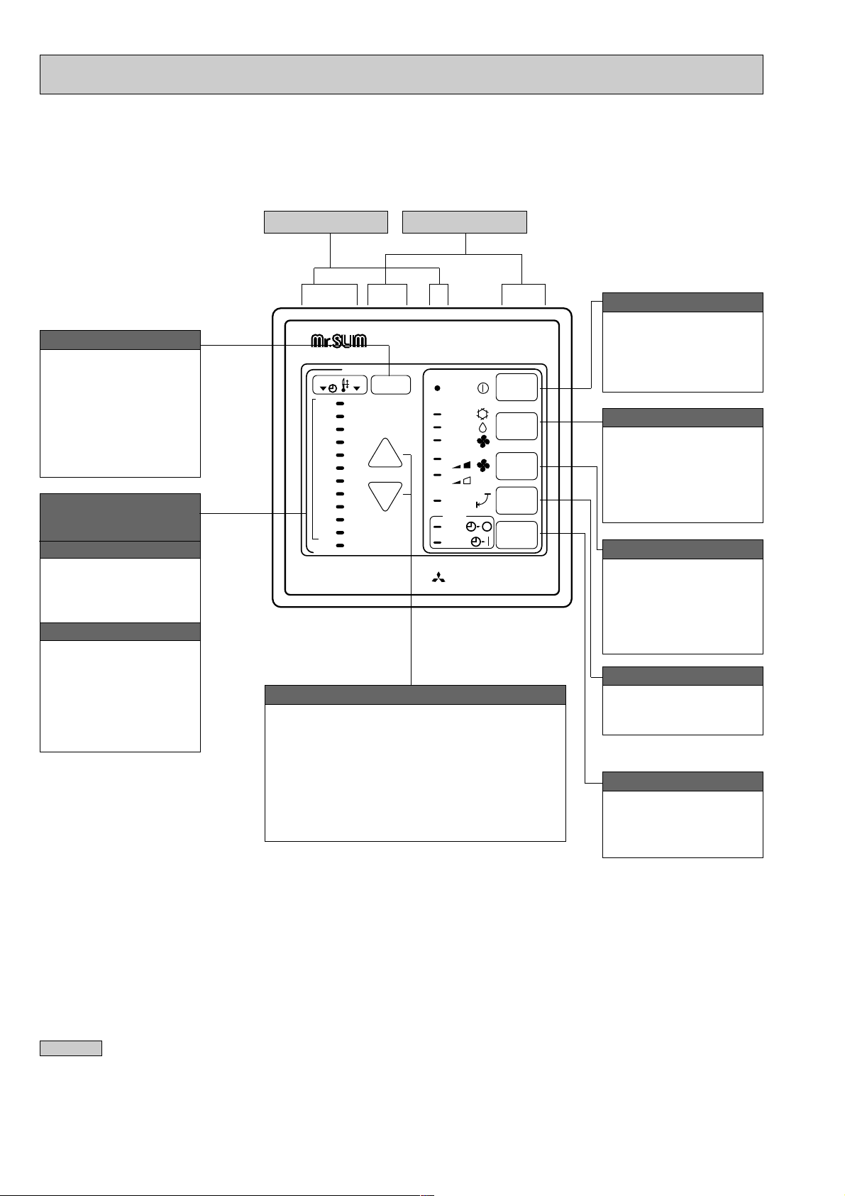
● Controller
Settings remain in effect' until changed. The air
conditioner can be operated by simply pressing
ON/OFF button once settings have been made.
MITSUBISHI ELECTRIC
12
11
10
9
8
7
6
5
4
3
2
1
29
28
27
26
25
24
23
22
21
20
19
18
TIMER TEMP
TIMER/TEMP.
UP
DOWN
POWER
COOL
ON/OFF
LOUVER
MODE
SELECT
FAN
SPEED
TIMER
MODE
DRY
FAN
HIGH
LOW
ON
AUTO
STOP
START
This button is used to
change between display of
room temperature and
display of remaining time
on the timer during “AUTO
STOP” operation.
Green lamps light in
selected display mode.
TIMER/TEMP. button
Pressing button starts
operation. Pressing again
stops operation.
Green lamp remains lit
during operation.
ON/OFF button
This button is used to
change between cooling,
DRYING and ventilation
operation modes. One of
three green lamps lights to
indicate mode in effect.
MODE SELECT button
This button is used to
change between low and
high fan speeds. One of
two green lamps lights to
indicate which fan speed is
in effect.
FAN SPEED button
Used to select timed
starting or stopping. Green
lamp lights to indicate timer
mode selected.
TIMER MODE button
This button is used to
switch swing louver
ON/OFF.
LOUVER button
●Temperature control (While green “TEMP” lamp
is lighting.)
Use UP and DOWN buttons to set desired
temperature between 18 and 29 °C.
●Timed operation (While green “TIMER“ lamp is
lighting.)
Use UP and DOWN buttons to set timed
operation between one and twelve hours.
UP and DOWN buttons
Lamps indicate time remaining
until timer stops operation.
Green lamps display the
remaining number of hours.
Lamps display temperature
settings actual room
temperatures.
●Temperature settings :
Green lamps light.
●Temperature in room :
Green lamps flash.
(Example display readings are
for explanations only, so actual
display readings will differ.)
Lamps display remaining
time on the timer or room
temperature.
Remaining timer time display
Room temperature display
Display panel
Operating panel
Page 5
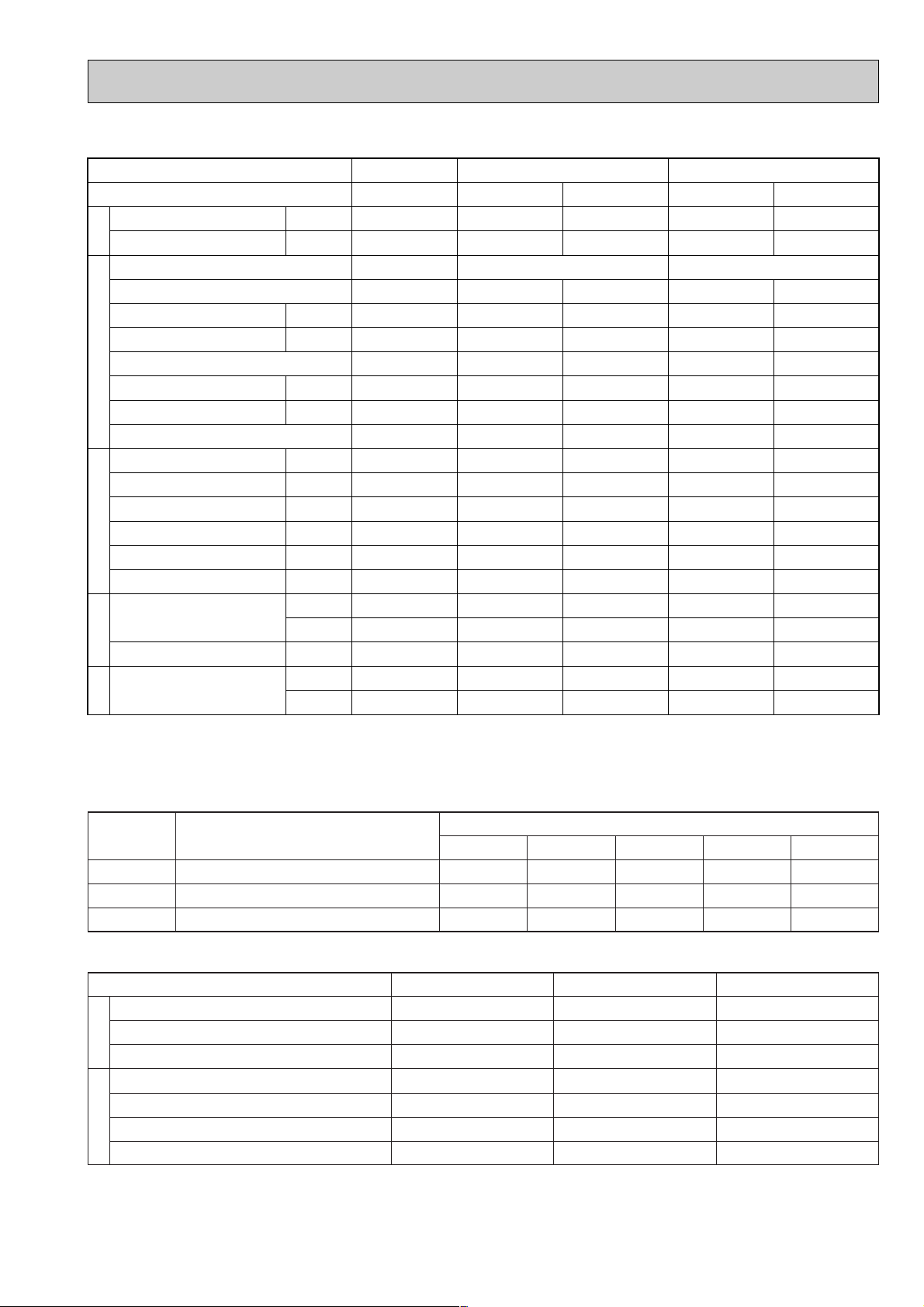
5
3
Service Ref.
External finish
Fan motor output
Airflow Lo-Hi
External static pressure
Operation control & Thermostat
Noise level Low-High
Cond. drain connection OD
Dimensions
Weight
External finish
Dimensions
Weight
Service Ref.
External finish
Refrigerant (R-22) control
Crankcase Heater w4
Compressor output
Protection devices
Fan motor output
Airflow
Noise level
Dimensions
Weight
W
Btu/h
W
Btu/h
W
Btu/h
kW
kW
CMM
CFM
CMM
CFM
mmAq,Pa
dB(A)
dB(A)
mm(in.)
mm(in.)
mm(in.)
mm(in.)
kg(lbs.)
mm(in.)
mm(in.)
mm(in.)
kg(lbs.)
W
kW
kW
CMM(CFM)
CMM(CFM)
dB(A)
mm(in.)
mm(in.)
mm(in.)
kg(lbs.)
50Hz
60Hz
60Hz
50Hz
60Hz
50Hz
60Hz
W
D
H
W
D
H
50/60Hz
50Hz
60Hz
50/60Hz
W
D
H
3,800
13,000
–
–
–
–
1.54/–
PL-1.6KJC
0.03
13-15
460-530
13-15
460-530
31-35
31-35
32 (1-1/4)
660 (26)
660 (26)
253 (10)
19 (42)
760 (30)
760 (30)
30 (1-1/8)
3.7 (8)
PU-1.6VLJA
2
–
1.2/w5
0.065
45(1588)
45(1588)
49/–
870(34-1/4)
650(25-5/8)
45(99)
5,600
19,100
5,400
18,400
4,500
15,400
2.57/2.59
PL-2KJC
Galvanized sheets with gray heat insulation
0.03
13-16
460-565
13-16
460-565
0 (Direct blow)
Remote control & Built-in
32-37
32-37
32 (1-1/4)
660 (26)
660 (26)
253 (10)
19 (42)
Munsell 0.70Y 8.59/0.97
760 (30)
760 (30)
30 (1-1/8)
3.7 (8)
PU-2VJA
2, PU-2NJA1
Munsell 5Y7/1
Capillary tube
32/–
2.0/1.5
0.065
45(1588)
45(1588)
49/50
870(34-1/4)
295+24(11-5/8+1)
650(25-5/8)
60(132)
6,500
22,200
7,000
23,900
5,950
20,300
2.59/3.05
PL-2.5KJC
0.03
14-17
495-600
14-17
495-600
35-39.5
35-39.5
32 (1-1/4)
660 (26)
660 (26)
253 (10)
20 (44)
760 (30)
760 (30)
30 (1-1/8)
3.7 (8)
PU-2.5VJA2, PU-2.5NJA
1
32/–
2.0/1.7
0.085
50(1765)
50(1765)
52/53
870(34-1/4)
850(33-7/16)
71(157)
Inner thermostat, HP switch, LP switch
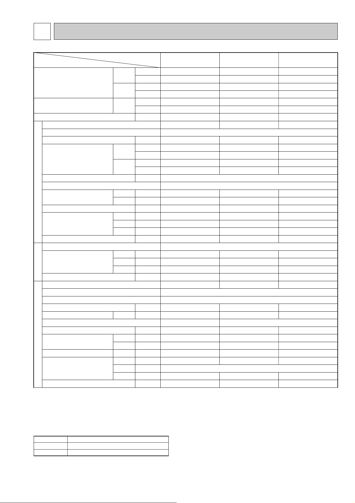
Cooling capacity w1
Cooling capacity w2
Total input (50/60Hz) w3
Item
Service Ref.
PL-1.6KJC PL-2KJC PL-2.5KJC
Indoor unitIndoor grillOutdoor unit
Notes :
w1 Rating conditions (JIS B8616) w2 Rating conditions (SSA 385, 386)
Indoor : 27°C (80°F) DB, 19°C (66°F)WB Indoor : 29°C (84°F) DB, 19°C (66°F)WB
Outdoor : 35°C (95°F) DB, 24°C (75°F)WB Outdoor : 46°C (115°F) DB, 24°C (75°F)WB
Refrigerant piping length (one way) : 5m (16ft) Refrigerant piping length (one way) : 5m (16ft)
w3 Total input based on indicated voltage w4 Capacity of crankcase heater (W) based on 220 volts.
w5 Motor protector, Thermal switch, HP/LP switch.
Service Ref. PL-1.6KJC / PL-2KJC / PL-2.5KJC
50Hz 1ph 220V/1ph 220V
60Hz 1ph 220V/1ph 220V
1. STANDARD SPECIFICATIONS
(Indoor / Outdoor)
Rating conditions (JIS B 8616)
SPECIFICATIONS
Page 6
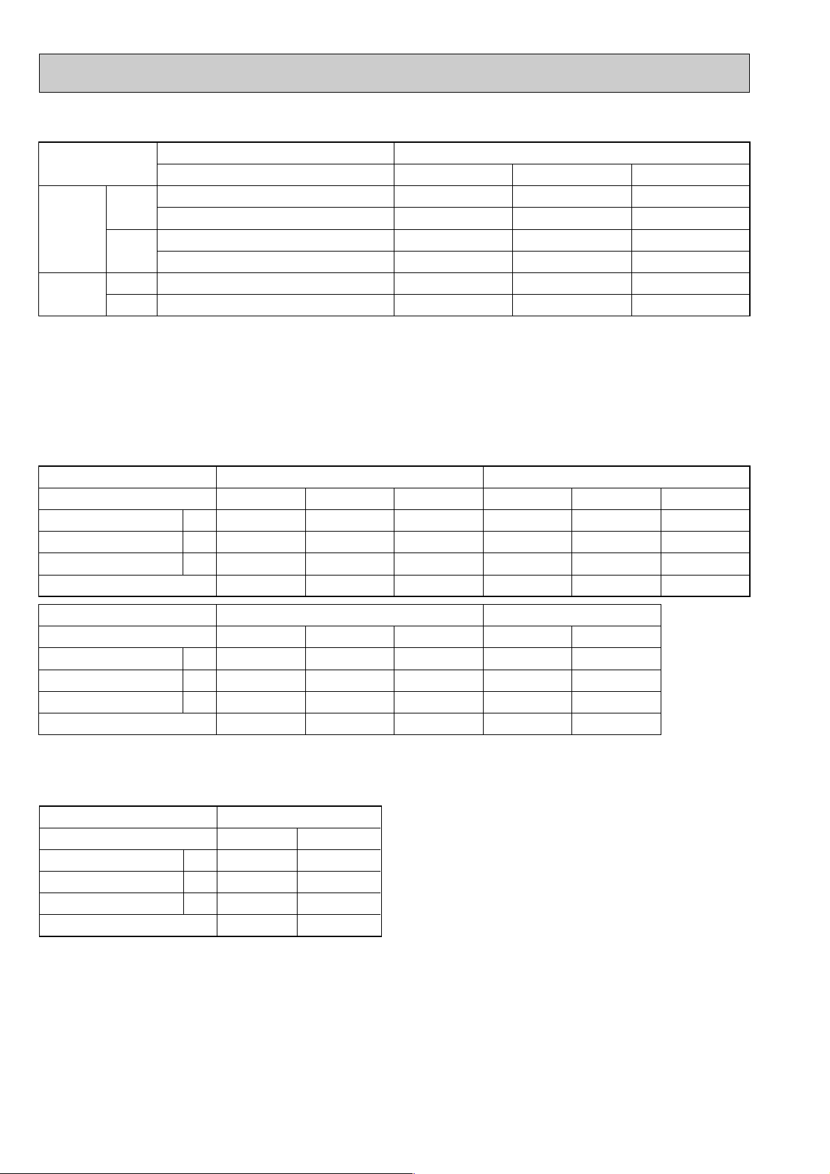
2. POWER SUPPLY & MODEL NAMES
Notes : 1. Power supply key N
......
1ph, 220V, 60Hz
V(L)
...
1ph, 220, 230, 240V, 50Hz
2. Primary power supplies for all indoor units are single-phase.
3. ELECTRICAL SPECIFICATIONS
(1). Rating conditions -JIS B 8616
Indoor : 27°C (80°F) DB, 19°C (66°F) WB
Outdoor : 35°C (95°F) DB, 24°C (75°F) WB
Series PL Indoor Unit (Single Phase)
6
(2). Rating conditions -SSA 385,386
Indoor : 27°C (80°F) DB, 19°C (66°F) WB
Outdoor : 35°C (95°F) DB, 24°C (75°F) WB
Series PL Indoor Unit (Single Phase)
A
kW
A
N : 220V 60Hz
PL-2KJC
0.65
0.14
0.72
PU-2NJA
1
PL-2.5KJC
0.66
0.14
0.73
PU-2.5NJA
1
Power supply (1 Phase)
Indoor unit Service Ref.
Current
Input
Starting current
Outdoor unit Service Ref.
Power supply
1ph.
50Hz
3ph.
60Hz
1ph.
3ph.
Service Ref. (Indoor unit) PL-1.6KJC
220V
220, 230, 240V
380/220V
380/220, 400/230, 415/240V
220V
220V
–
PU-1.6VLJA
–
–
–
–
Model name (Outdoor unit)
PL-2KJC
–
2
PU-2VJA
2
–
–
PU-2NJA
1
–
PL-2.5KJC
–
PU-2.5VJA
–
–
PU-2.5NJA
–
2
1
Power supply (1 Phase)
Indoor unit Service Ref.
Current
Input
Starting current
Outdoor unit Service Ref.
A
kW
A
PL-1.6KJC
0.59
0.12
0.65
PU-1.6VLJA
Power supply (1 Phase)
Indoor unit Service Ref.
Current
Input
Starting current
Outdoor unit Service Ref.
A
kW
A
PL-1.6KJC
0.64
0.14
0.70
PU-1.6VLJA
V : 220V 50Hz V : 230V 50Hz
PL-1.6KJC
2
PU-1.6VLJA
2
PL-2KJC
0.60
0.13
0.66
PU-2VJA
2
PL-2.5KJC
0.60
0.13
0.66
PU-2.5VJA
V : 240V 50Hz N : 220V 60Hz
2
PL-2KJC
0.65
0.15
0.72
PU-2VJA
2
PL-2.5KJC
0.65
0.15
0.72
PU-2.5VJA
2
0.62
0.13
0.68
PL-2KJC
0.65
0.14
0.72
PU-2NJA
2
1
PL-2KJC
0.63
0.14
0.69
PU-2VJA
PL-2.5KJC
0.66
0.14
0.73
PU-2.5NJA
2
1
PL-2.5KJC
0.63
0.14
0.69
PU-2.5VJA
2
Page 7
7
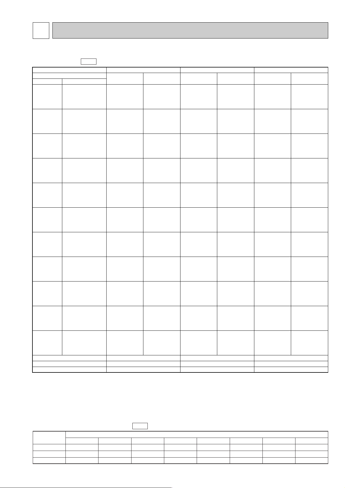
4
DATA
1. PERFORMANCE DATA
Cooling capacity 50Hz
PL-2.5KJCPL-2KJC
17
0.10
0.75
Evaporator airflow (CMM)
Bypass factors
S.H.F. at rating conditions
16
0.19
0.81
15
0.31
0.80
Service Ref.
Temperature
16$C (60.8$F
)
18$C (64.4$F
)
19$C (66.2$F
)
19.4$C (67$F
)
20$C (68$F
)
22$C (71.6$F
)
PL-1.6KJC
0.81
0.82
0.83
0.83
0.84
0.85
16$C (60.8$F
)
18$C (64.4$F
)
19$C (66.2$F
)
19.4$C (67$F
)
20$C (68$F
)
22$C (71.6$F
)
3.8
4.0
4.1
4.2
4.3
4.5
0.83
0.85
0.86
0.86
0.87
0.88
5.3
5.7
5.8
5.9
6.0
6.4
0.83
0.85
0.86
0.86
0.87
0.88
6.4
6.8
7.0
7.2
7.3
7.8
0.83
0.85
0.86
0.86
0.87
0.88
16$C (60.8$F
)
18$C (64.4$F
)
19$C (66.2$F
)
19.4$C (67$F
)
20$C (68$F
)
22$C (71.6$F
)
3.5
3.7
3.8
3.8
3.9
4.2
0.97
0.99
1.00
1.01
1.02
1.04
4.9
5.2
5.4
5.5
5.6
5.9
0.97
0.99
1.00
1.01
1.02
1.04
5.9
6.3
6.5
6.6
6.7
7.2
0.97
0.99
1.00
1.01
1.02
1.04
1.03
1.05
1.06
1.07
1.08
1.12
16$C (60.8$F
)
18$C (64.4$F
)
19$C (66.2$F
)
19.4$C (67$F
)
20$C (68$F
)
22$C (71.6$F
)
16$C (60.8$F
)
18$C (64.4$F
)
19$C (66.2$F
)
19.4$C (67$F
)
20$C (68$F
)
22$C (71.6$F
)
16$C (60.8$F
)
18$C (64.4$F
)
19$C (66.2$F
)
19.4$C (67$F
)
20$C (68$F
)
22$C (71.6$F
)
3.3
3.6
3.6
3.7
3.8
4.1
1.03
1.05
1.06
1.07
1.08
1.12
4.7
5.1
5.2
5.2
5.3
5.8
1.03
1.05
1.06
1.07
1.08
1.12
5.7
6.1
6.2
6.3
6.4
7.0
1.03
1.05
1.06
1.07
1.08
1.12
1.09
1.12
1.14
1.15
1.16
1.20
3.2
3.3
3.5
3.6
3.6
3.8
1.10
1.13
1.15
1.16
1.17
1.21
4.5
4.8
5.0
5.1
5.2
5.5
1.10
1.13
1.15
1.16
1.17
1.21
5.4
5.7
6.0
6.1
6.2
6.6
1.10
1.13
1.15
1.16
1.17
1.21
1.16
1.19
1.21
1.22
1.23
1.28
2.9
3.1
3.2
3.3
3.3
3.6
1.18
1.22
1.24
1.25
1.26
1.32
4.2
4.4
4.6
4.6
4.8
5.1
1.18
1.22
1.24
1.25
1.26
1.32
5.0
5.3
5.5
5.6
5.7
6.2
1.18
1.22
1.24
1.25
1.26
1.32
16$C (60.8$F
)
18$C (64.4$F
)
19$C (66.2$F
)
19.4$C (67$F
)
20$C (68$F
)
22$C (71.6$F
)
3.6
3.8
4.0
4.0
4.1
4.3
0.90
0.92
0.93
0.93
0.94
0.96
5.1
5.5
5.6
5.8
5.8
6.2
0.90
0.92
0.93
0.93
0.94
0.96
6.2
6.6
6.8
6.8
7.0
7.4
0.90
0.92
0.93
0.93
0.94
0.96
21$C
(69.8$F)
25$C
(77$F)
30$C
(86$F)
32.2$C
(90$F)
35$C
(95$F)
40$C
(104$F)
40.6$C
(105$F)
45$C
(113$F)
46$C
(115$F)
50$C
(122$F)
52$C
(125.5$F)
16$C (60.8$F
)
18$C (64.4$F
)
19$C (66.2$F
)
19.4$C (67$F
)
20$C (68$F
)
22$C (71.6$F
)
16$C (60.8$F
)
18$C (64.4$F
)
19$C (66.2$F
)
19.4$C (67$F
)
20$C (68$F
)
22$C (71.6$F
)
16$C (60.8$F
)
18$C (64.4$F
)
19$C (66.2$F
)
19.4$C (67$F
)
20$C (68$F
)
22$C (71.6$F
)
16$C (60.8$F
)
18$C (64.4$F
)
19$C (66.2$F
)
19.4$C (67$F
)
20$C (68$F
)
22$C (71.6$F
)
3.8
4.1
4.2
4.3
4.3
4.6
3.6
3.8
3.9
4.0
4.1
4.3
3.3
3.6
3.6
3.7
3.8
4.1
3.2
3.4
3.5
3.6
3.7
3.9
3.0
3.2
3.3
3.3
3.4
3.6
5.5
5.8
5.9
6.0
6.2
6.5
6.6
7.0
7.2
7.3
7.4
7.8
5.1
5.4
5.6
5.7
5.8
6.2
6.1
6.5
6.7
6.8
7.0
7.4
4.7
5.1
5.2
5.2
5.3
5.8
5.7
6.1
6.2
6.3
6.4
7.0
4.5
4.8
5.0
5.1
5.2
5.5
5.5
5.8
6.0
6.2
6.3
6.6
4.2
4.5
4.7
4.8
4.9
5.2
5.1
5.5
5.7
5.7
5.9
6.2
0.81
0.82
0.83
0.83
0.84
0.85
0.81
0.82
0.83
0.83
0.84
0.85
0.91
0.93
0.95
0.95
0.96
0.98
0.91
0.93
0.95
0.95
0.96
0.98
0.91
0.93
0.95
0.95
0.96
0.98
1.03
1.05
1.06
1.07
1.08
1.12
1.03
1.05
1.06
1.07
1.08
1.12
1.09
1.12
1.14
1.15
1.16
1.20
1.09
1.12
1.14
1.15
1.16
1.20
1.16
1.19
1.21
1.22
1.23
1.28
1.16
1.19
1.21
1.22
1.23
1.28
Indoor WBOutdoor DB
T.C. C.F.
(T.I.)
C.F.
(T.I.)
T. C.C.F.
(T.I.)
T. C.
Notes : 1. T.C. : Total capacity (kW) ... (kcal/h) = (kW) ✕ 860, (Btu/h) = 4 ✕ (kW) ✕ 860
C.F. (T.I.) : Correction factors of Total input (Indoor unit input + Outdoor unit input)
2. (°F) = 32 + 9 / 5 (°C)
3. Guaranteed operation range (cooling) :
Lower limit ... Indoor : 21°C (70°F) DB, 15.5°C (60°F) WB, Outdoor : 21°C (70°F) DB.
Upper limit ... Indoor : 35°C (95°F) DB, 22.5°C (72.5°F) WB, Outdoor : 52°C (125.5°F) DB. w
wVL ... Outdoor : 46°C (115°F) DB.
Cooling capacity correction factors 50Hz
PL-1.6KJC
PL-2KJC
PL-2.5KJC
Service Ref.
Refrigerant piping length (one way)
5m (16ft)
1.0
1.0
1.0
10m (33ft)
0.992
0.985
0.983
15m (49ft)
0.987
0.975
0.972
20m (66ft)
0.982
0.964
0.961
25m (82ft)
–
0.954
0.951
30m (98ft)
–
0.944
0.940
35m (115ft)
–
–
–
40m (131ft)
–
–
–
Page 8
8
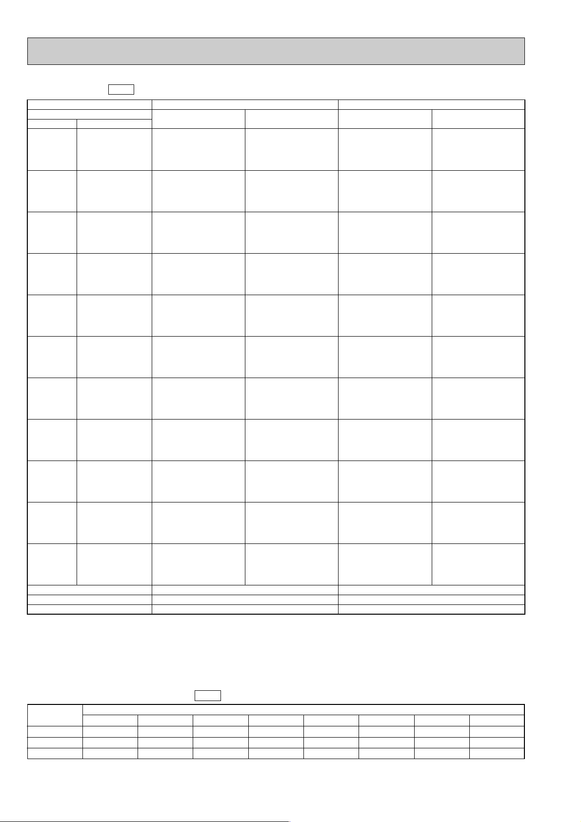
Cooling capacity 60Hz
Notes : 1. T.C. : Total capacity (kW)
...
(kcal/h) = (kW) ✕ 860, (Btu/h) = 4 ✕ (kW) ✕ 860
C.F. (T.I.) : Correction factors of Total input (Indoor unit input + Outdoor unit input)
2. (°F) = 32 + 9 / 5 (°C)
3. Guaranteed operation range (cooling) :
Lower limit ... Indoor : 21°C (70°F) DB, 15.5°C (60°F) WB, Outdoor : 21°C (70°F) DB.
Upper limit ... Indoor : 35°C (95°F) DB, 22.5°C (72.5°F) WB, Outdoor : 52°C (125.5°F) DB.
PL-2.5KJC
17
0.09
0.79
Evaporator airflow (CMM)
Bypass factors
S.H.F. at rating conditions
16
0.19
0.76
Service Ref.
Temperature
16$C (60.8$F
)
18$C (64.4$F
)
19$C (66.2$F
)
19.4$C (67$F
)
20$C (68$F
)
22$C (71.6$F
)
PL-2KJC
16$C (60.8$F
)
18$C (64.4$F
)
19$C (66.2$F
)
19.4$C (67$F
)
20$C (68$F
)
22$C (71.6$F
)
5.3
5.7
5.8
5.9
6.0
6.4
0.83
0.85
0.86
0.86
0.87
0.88
6.9
7.4
7.6
7.7
7.8
8.3
16$C (60.8$F
)
18$C (64.4$F
)
19$C (66.2$F
)
19.4$C (67$F
)
20$C (68$F
)
22$C (71.6$F
)
4.9
5.2
5.4
5.5
5.6
5.9
0.97
0.99
1.00
1.01
1.02
1.04
6.4
6.8
7.0
7.1
7.2
7.7
16$C (60.8$F
)
18$C (64.4$F
)
19$C (66.2$F
)
19.4$C (67$F
)
20$C (68$F
)
22$C (71.6$F
)
16$C (60.8$F
)
18$C (64.4$F
)
19$C (66.2$F
)
19.4$C (67$F
)
20$C (68$F
)
22$C (71.6$F
)
16$C (60.8$F
)
18$C (64.4$F
)
19$C (66.2$F
)
19.4$C (67$F
)
20$C (68$F
)
22$C (71.6$F
)
4.7
5.1
5.2
5.2
5.3
5.8
1.03
1.05
1.06
1.07
1.08
1.12
6.1
6.6
6.7
6.8
6.9
7.5
4.5
4.8
5.0
5.1
5.2
5.5
1.10
1.13
1.15
1.16
1.17
1.21
5.8
6.2
6.4
6.6
6.7
7.1
4.2
4.4
4.6
4.6
4.8
5.1
1.18
1.22
1.24
1.25
1.26
1.32
5.4
5.7
6.0
6.0
6.2
6.7
16$C (60.8$F
)
18$C (64.4$F
)
19$C (66.2$F
)
19.4$C (67$F
)
20$C (68$F
)
22$C (71.6$F
)
5.1
5.5
5.6
5.8
5.8
6.2
0.90
0.92
0.93
0.93
0.94
0.96
6.7
7.1
7.3
7.4
7.5
8.0
21$C
(69.8$F)
25$C
(77$F)
30$C
(86$F)
32.2$C
(90$F)
35$C
(95$F)
40$C
(104$F)
40.6$C
(105$F)
45$C
(113$F)
46$C
(115$F)
50$C
(122$F)
52$C
(125.5$F)
16$C (60.8$F
)
18$C (64.4$F
)
19$C (66.2$F
)
19.4$C (67$F
)
20$C (68$F
)
22$C (71.6$F
)
16$C (60.8$F
)
18$C (64.4$F
)
19$C (66.2$F
)
19.4$C (67$F
)
20$C (68$F
)
22$C (71.6$F
)
16$C (60.8$F
)
18$C (64.4$F
)
19$C (66.2$F
)
19.4$C (67$F
)
20$C (68$F
)
22$C (71.6$F
)
16$C (60.8$F
)
18$C (64.4$F
)
19$C (66.2$F
)
19.4$C (67$F
)
20$C (68$F
)
22$C (71.6$F
)
5.5
5.8
5.9
6.0
6.2
6.5
5.1
5.4
5.6
5.7
5.8
6.2
4.7
5.1
5.2
5.2
5.3
5.8
4.5
4.8
5.0
5.1
5.2
5.5
4.2
4.5
4.7
4.8
4.9
5.2
0.81
0.82
0.83
0.83
0.84
0.85
0.91
0.93
0.95
0.95
0.96
0.98
1.03
1.05
1.06
1.07
1.08
1.12
1.09
1.12
1.14
1.15
1.16
1.20
1.16
1.19
1.21
1.22
1.23
1.28
0.83
0.85
0.86
0.86
0.87
0.88
0.97
0.99
1.00
1.01
1.02
1.04
1.03
1.05
1.06
1.07
1.08
1.12
1.10
1.13
1.15
1.16
1.17
1.21
1.18
1.22
1.24
1.25
1.26
1.32
0.90
0.92
0.93
0.93
0.94
0.96
0.81
0.82
0.83
0.83
0.84
0.85
0.91
0.93
0.95
0.95
0.96
0.98
1.03
1.05
1.06
1.07
1.08
1.12
1.09
1.12
1.14
1.15
1.16
1.20
1.16
1.19
1.21
1.22
1.23
1.28
7.1
7.5
7.7
7.8
8.0
8.4
6.6
7.0
7.2
7.4
7.5
8.0
6.1
6.6
6.7
6.8
6.9
7.5
5.9
6.2
6.5
6.7
6.8
7.1
5.5
5.9
6.1
6.2
6.3
6.7
Indoor WBOutdoor DB
C.F.
(T.I.)
T. C.C.F.
(T.I.)
T. C.
Cooling capacity correction factors 60Hz
PL-1.6KJC
PL-2KJC
PL-2.5KJC
Service Ref.
Refrigerant piping length (one way)
5m (16ft)
1.0
1.0
1.0
10m (33ft)
0.990
0.985
0.978
15m (49ft)
0.983
0.975
0.963
20m (66ft)
0.976
0.964
0.948
25m (82ft)
–
0.954
0.934
30m (98ft)
–
0.944
0.921
35m (115ft)
–
–
–
40m (131ft)
–
–
–
Page 9
9
2. STANDARD OPERATION DATA
w The air coverage range is the value up to the position where the air speed is 0.25 m/sec. when air is blown out horizontally
from the unit at the Hi notch position.
The coverage range should be used only as a general guideline since it varies according to the size of the room and furniture
inside the room.
The unit of pressure has been changed to Mpa based on the international SI system.
The converston factor is : 1(Mpa.G)=10.2(of/
f
.
G)
3. ADDITIONAL REFRIGERANT CHARGE (R-22
......
Kg(lbs))
4. OUTLET AIR SPEED AND COVERAGE RANGE
Capacity
Input
Indoor unit Service Ref.
phase, Hz
Volts
Amperes
Outdoor unit Service Ref.
phase, Hz
Volts
Amperes
Discharge pressure
Suction pressure
Discharge temperature
Condensing temperature
Suction temperature
Ref. pipe length
Intake air temperature
Discharge air temperature
Intake air temperature
W
kW
V
A
V
A
$C
$C
$C
m
DB$C
WB$C
DB$C
DB$C
WB$C
PL-1.6KJC
cooling
3,800
1.54
PL-1.6KJC
1, 50
220
0.59
PU-1.6VLJA
2
1, 50
220
7.7
(19.8)
(5.3)
62.3
37.4
8.3
5
27
19
17.1
35
24
cooling
5,600
2.57
1, 50
220
0.60
PU-2VJA
2
1, 50
220
11.3
(19.9)
(4.6)
75.9
48.9
13.1
5
27
19
15.5
35
24
PL-2KJCService Ref.
Electrical circuit TotalRefrigerant circuit
Indoor side
Outdoor
side
MODE
PL-2.5KJC
PL-2KJC PL-2.5KJC
cooling
5,400
2.59
1, 60
220
0.65
PU-2NJA
1
1, 60
220
11.9
(19.9)
(4.9)
63.6
46.0
5.8
5
27
19
14.6
35
24
cooling
6,500
2.59
1, 50
220
0.60
PU-2.5VJA
2
1, 50
220
12.5
(19.6)
(4.9)
74.3
46.4
10.3
5
27
19
13.1
35
24
cooling
7,000
3.05
1, 60
220
0.66
PU-2.5NJA
1
1, 60
220
13.5
(20.7)
(4.8)
83.4
47.6
7.2
5
27
19
13.0
35
24
Mpa.G
(kgf/F.G)
Mpa.G
1.94
0.52
1.95
0.45
1.95
0.48
1.92
0.48
2.03
0.47
(kgf/F.G)
Service Ref.
PL-1.6KJC
PL-2KJC
PL-2.5KJC
Outdoor unit precharged (kg)
(up to 20m)
V
...
1.3
V
...
1.78, N
...
1.9
V
...
2.4, N
...
2.4
Refrigerant piping length (one way)
20m(66ft)
0
0
0
25m(82ft)
–
0.06(0.13)
0.06(0.13)
30m(98ft)
–
0.12(0.26)
0.12(0.26)
35m(115ft)
–
–
–
40m(131ft)
–
–
–
Air flow
Air speed
Coverage range
Air flow
Air speed
Coverage range
Total width of discharge outlets
CMM
m/sec.
m
CMM
m/sec.
m
mm
PL-1.6KJC
15.0
5.2
5.7
16.0
5.6
6.0
0
PL-2KJC
16.0
5.6
6.0
17.0
5.9
6.4
0
PL-2.5KJC
17.0
5.9
6.4
18.0
6.3
6.8
0
Standard
High ceiling
Page 10
10
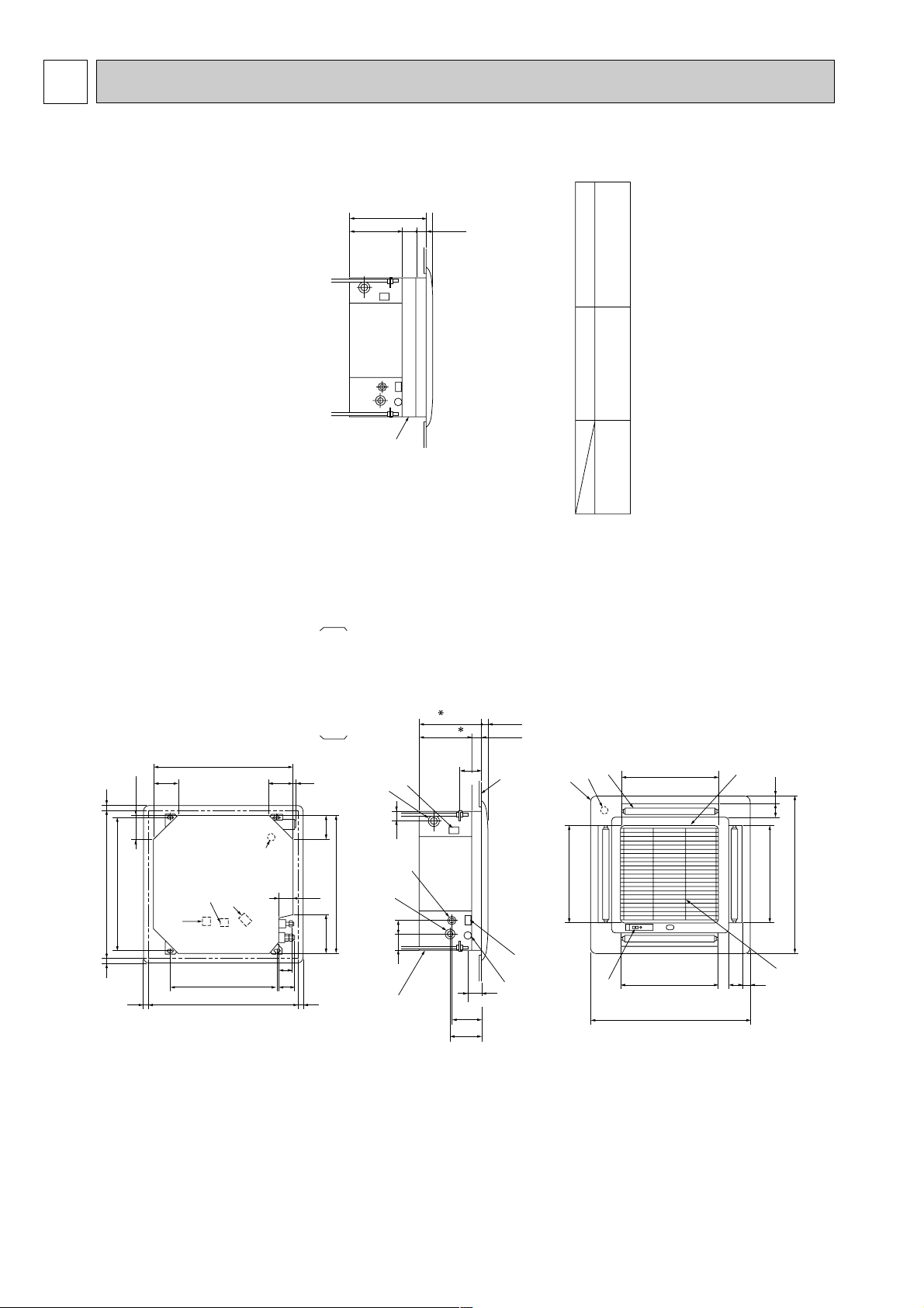
5
OUTLINES AND DIMENSIONS
1. INDOOR UNIT
PL-1.6KJC / PL-2KJC / PL-2.5KJC
Terminal block
Terminal block
for remote controller
Power terminal block
Drain water release hole
Ceiling hole
Ceiling hole
Suspension bolt pitch
640
690~710
25~3525~35
117
186
660
117
13
64
77 507
25~35
145
154
25~35
Suspension bolt pitch
690~710
117117
660
68
2
1
75 65
65~80
115
253
29830
54
+3
-2
42
Drain pipe
Connected to VP-25
Inspection hole
(Drain up machine)
Keep approximately
10 to 15mm space
between unit ceiling and ceilimg slab.
Ceiling side
Suspension bolt M10
or W3/8
Suspension bolt lower edge
Control wire opening
135
435
54
+3
-2
Power switch wire opening
Refrigerant piping side
Wiring arrangement opening side
A (Indication area)
Wired panel
A
Connect the attached
flexible pipe or socket.
466
Air intake
460
66 35
6635
760
Air outlet
460
760
Air outlet
466
Air intake
Grill
Vane motor
4-Auto vane
Intake grille opening closing side.
Intake grille
(Air intake)
Optional multifunctional casement
Optional high performance filter
1 (Liquid) 2 (Gas)
1/6/2/2.5
Refrigerant pipe {9.52
Flaredconnection 3/8F
Refrigerant pipe {15.88
Flaredconnection 5/8F
Note 1:
Note 2:
Note 3:
For the installation of the optional humidifier(suspended type), it
requires minimum 360mm space between transom and ceiling.
Electrical box may be removed for the service purpose. Make
sure to slack the electrical wire little bit for control/power wires
connection.
For the installation of the optional high efficiency filter or optional
multiple casement, it requires minimum 440mm space between
transom and ceiling for the installation (Optional high
performance filter can be also installed).
Page 11
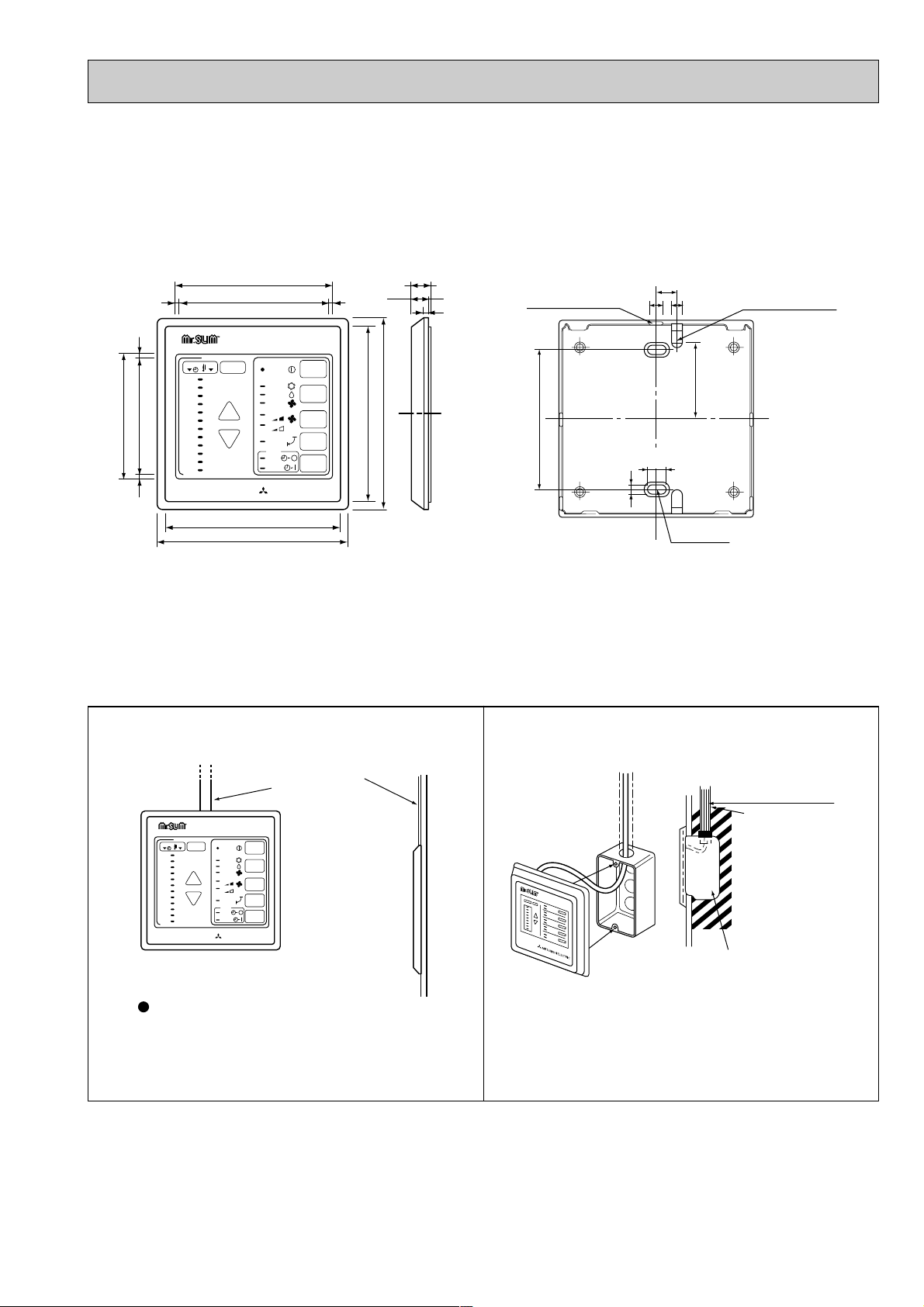
11
2. REMOTE CONTROLLER
Remote controller cable installation
MITSUBISHI ELECTRIC
12
11
10
9
8
7
6
5
4
3
2
1
29
28
27
26
25
24
23
22
21
20
19
18
TIMER TEMP
TIMER/TEMP.
UP
DOWN
POWER
COOL
ON/OFF
LOUVER
MODE
SELECT
FAN
SPEED
TIMER
MODE
DRY
FAN
HIGH
LOW
ON
AUTO
STOP
START
75
69
108(4-1/4)
117(4-5/8)
108(4-1/4)
96.5
12(15/32)
90.5
11.6
3.6
33
117(4-5/8)
33
Rear side wiring
arrangememt opening
Upper side wiring
arrangement
opening
Fixing hole
83.5(3-9/32)
12(15/32)
86
4.6
46
9.2
MITSUBISHI ELECTRIC
12
11
10
9
8
7
6
5
4
3
2
1
29
28
27
26
25
24
23
22
21
20
19
18
TIMER TEMP
TIMER/TEMP.
UP
DOWN
POWER
COOL
ON/OFF
LOUVER
MODE
SELECT
FAN
SPEED
TIMER
MODE
DRY
FAN
HIGH
LOW
ON
AUTO
STOP
START
Exposed remote controller
cable
Cable connection is only from the top.
(right, left and bottom not possible)
Remote controller cable
Conduit tube
(local arrangement)
Switch box
(local arrangement)
Set screw (match with switch box),
local arrangement.
●For exposed remote controller cable installation
Note : The cable for the remote controller is 5m (16ft) and 12-core with connectors O.D. ø 5.8.
●For recessed remote controller cable installation
Unit : mm (inch)
Page 12
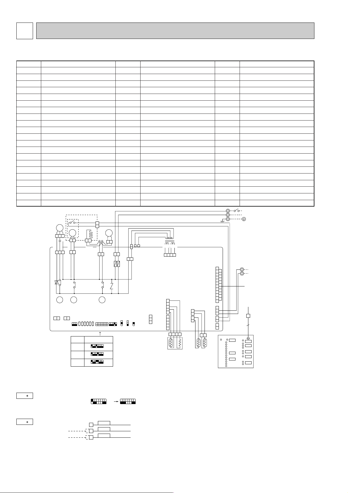
12
NOTES:
1. Since the Indoor fan motor (MF) is connected with 220V power, using 230,
240V power will require a setting change of the dip switch (SW<I. B>) on the
indoor controller board as shown in fig : ❈1.
2. Since the indoor transformer (T) is connected with 220V power, using 230,
240V power will require a wiring connection change as shown in fig : ❈2.
3. Since the outdoor side electric wiring may change, be sure to check the
outdoor unit electric wiring for servicing.
4. Emergency operation
If remote controller or microcomputer fails but there is no other trouble,
emergency operation is possible by setting dip switch (SW3<I. B>) on the
indoor controller board.
WIRING DIAGRAM
6
[Check items]
(1) Compressor and fan.
(2) Check the trouble position using self diagnostic function. If the result of self
diagnosis indicates protective device such as freeze protection is functioning,
emergency operation is not possible unless the cause is removed.
(3) Do not attempt emergency operation when drain pump fails (drain overflows).
(4) Emergency operation will continuously run with power ON/OFF (ON/OFF with
remote controller is not possible).
[Emergency operation procedure]
(1) Set the dip switch (SW3<I.B>) on the indoor controller board to 1.2 on and 3
off for cooling.
(2) Turn on outdoor unit side circuit breaker, then indoor unit side circuit breaker in
this order.
(3) During emergency operation indoor fan runs at high speed but vane remains
stop.
(4) Thermostat will not function.
(5) Emergency cooling should be limited to 10 hours maximum (the indoor unit
heat exchanger may freeze).
SYMBOL NAME
I.B
MF
MV
LS
RT1
RT2
DS
DP
T
C1
TB2
TB4
CND<I.B>
FAN1<I.B>
CNV<I.B>
CNP<I.B>
CN30<I.B>
CN120<I.B>
CN23<I.B>
CN20<I.B>
CN21<I.B>
INDOOR CONTROLLER BOARD
INDOOR FAN MOTOR
VANE MOTOR
LIMIT SWITCH
ROOM TEMPERATURE THERMISTOR (0°C/15k1, 25°C/5.4k1)
INDOOR COIL THERMISTOR (0°C/15k1, 25°C/5.4k1)
DRAIN SENSOR
DRAIN PUMP
TRANSFORMER
INDOOR FAN CAPACITOR
POWER SUPPLY TERMINAL BLOCK
INDOOR/OUTDOOR CONNECTING WIRE TERMINAL BLOCK
POWER SUPPLY CONNECTOR
FAN MOTOR CONNECTOR
VANE MOTOR CONNECTOR
DRAIN PUMP CONNECTOR
INDOOR/OUTDOOR CONNECTING WIRE CONNECTOR
REMOTE CONTROLLER TRANSMISSION WIRE CONNECTOR
VANE POSITION CONNECTOR
INTAKE CONNECTOR
PIPE CONNECTOR
PL-1.6KJC / PL-2KJC / PL-2.5KJC
SYMBOL
NAME
CN50<I.B>
CN51<I.B>
CN2A<I.B>
CN2B<I.B>
CN28<I.B>
CN2<I.B>
SW1<I.B>
SW2<I.B>
SW3<I.B>
SWA<I.B>
SWB<I.B>
SWC<I.B>
X1<I.B>
X3<I.B>
X4<I.B>
F1<I.B>
F2<I.B>
ZNR<I.B>
H
R.B
CNR120<R.B>
DRAIN SENSOR CONNECTOR
MULTIPLE CONNECTOR
TRANSMISSION WIRES No.1 CONNECTOR
TRANSMISSION WIRES No.2 CONNECTOR
TIME SHORTENING CONNECTOR
TIMER ADAPTOR CONNECTOR
FUNCTION SWITCH
UNIT SWITCH
EMERGENCY OPERATION SWITCH
HIGH CEILING, NOISE SAVING SWITCH
NUMBER OF AIR OUTLETS SWITCH
OPTION SWITCH
DRAIN PUMP/D.HEATER RELAY
VANE MOTOR RELAY
FAN MOTOR RELAY
FUSE (6.3A)
FUSE (6.3A)
VARISTOR
DEW PREVENTION HEATER
REMOTE CONTROLLER BOARD
CONNECTOR (REMOTE CONTROLLER TRANSMISSION WIRE)
SYMBOL NAME
SW1<R.B>
SW2<R.B>
SW3<R.B>
SW4<R.B>
SW5<R.B>
SW6<R.B>
SW7<R.B>
SW8<R.B>
LD1<R.B>
LD3<R.B>
LD4<R.B>
LD5<R.B>
LD6<R.B>
LD7<R.B>
LD8<R.B>
LD9<R.B>
LD10<R.B>
LD11<R.B>
LD12<R.B>
LD13~24<R.B>
ON/OFF SWITCH
MODE SWITCH
FAN SPEED HIGH/LOW SELECTOR SWITCH
VANE ON/OFF SWITCH
DISPLAY SWITCH
SET TEMPERATURE/TIMER UP SWITCH
SET TEMPERATURE/TIMER DOWN SWITCH
TIMER MODE SWITCH
RUN INDICATOR LED
COOLING INDICATOR LED
FAN MODE INDICATOR LED
FAN HIGH INDICATOR LED
VANE ON INDICATOR LED
INDICATOR MODE TEMPERATURE LED
INDICATOR MODE TIMER LED
DRY INDICATOR LED
FAN LOW INDICATOR LED
OFF TIMER INDICATOR LED
ON TIMER INDICATOR LED
TEMPERATURE TIMER REMAINING TIME INDICATOR LED
MF
MV
1 2 3
1 3 5
1 2
2 7
1 3
X4
X4
X3 X1
X3 X1
ZNR
C1
RED
WHT
BLK
YLW
YLW
FAN1
FAN
CNV
VAME
CN2B
TWN1
2
1
3
CN2
TIMER
2
1
3
4
5
CN51
MULTIPLE
4
5
3
2
1
2
1
1
2
1
2
3
1
12
2
1
2
1
2
1
CN50
DRAIN
CN21
PIPE
CN30
OUTDOOR
CN23
VANE
CN28
LINE TEST
CN120
TO.R.C
CN20
INTAKE
1 2
CN2A
TWN2
123
JR01
SW3
12345678
SW1
JR02
JR03
JR04
JR05
JR06
12345678
12345
3
2
1
SW2
SWA
2
3
4
SWB
STD
OP
SWC
I.B
ON
OFF
PL-1.6KJC
Service Ref.
SW1
12345678
ON
OFF
PL-2KJC
12345678
ON
OFF
PL-2.5KJC
LD8
LD13
LD1
LD3
LD9
LD4
LD5
LD10
LD6
LD11
LD12
LD14
LD15
LD16
LD17
LD18
LD19
LD20
LD21
LD22
LD23
LD24
LD7
SW5
SW6
SW7
SW8
SW4
SW3
SW2
SW1
R.B.
12
CNR120
1 2 3 4
DS
RT1 RT2
GRY
BLK
BLK
BRN
YLW
ORN
TB4
TO OUTDOOR UNIT
CONNECTING WIRES
12V DC
N
L
TB2
GRN/YLW
POWER SUPPLY
~(1PHASE)
220-240V AC 50Hz
220V AC 60Hz
1 2
1LB6
CNP
D.U.M
F2 F1
YLW
1 3
1 3
4 3 2 1
CND
POWER
CNT
TARNS
CN4T
TARNS
DP
N
BRN
5
10
BLU
BRN
BRN
BRN
BRN
RED
BLU
WHT
RED
220V
230V
240V
ORN
YLW
BLU
RED BRN
T
14.5V AC 10.6V AC
fig : 1
Indoor fan motor (MF) for 230, 240V.
1 2 3 4 5 6 7 8
SW1
ON
OFF
1 2 3 4 5 6 7 8
SW1
ON
OFF
When power supply is
230V
240V
fig : 2
220V
RED
230V
ORANGE
240V
YELLOW
Page 13
13
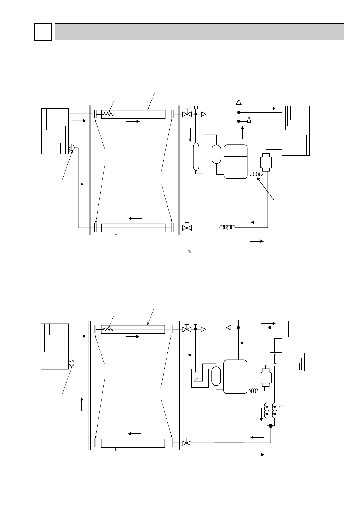
INDOOR UNIT
PL-1.6KJC
PL-2KJC
Indoor heat
exchanger
OUTDOOR UNIT
PU-1.6JA
PU-2JA
Outdoor heat
exchanger
Capillary tube
for injection
(Only PU-2)
Distributor
Flexible tube
Flared
connection
Flared
connection
Ball valve
(with service port)
Refrigerant pipe {9.52(3/8)
(With insulator) option
Refrigerant pipe {15.88(5/8)
(With insulator) option
Accumulator
Compressor
Capillary tube
Capillary tube size
: flow of refrigerant
PU-1.6(O.D.3.2XI.D.1.8–R900)
PU-2 (O.D.3.2
X
I.D.2.0–R430)
Strainer
Check
plug
High pressure
switch
Low pressure
switch
Charge
plug
Ball
valve
INDOOR UNIT
PL-2.5KJC
Indoor heat
exchanger
OUTDOOR UNIT
PU-2.5JA
Outdoor heat
exchanger
Capillary tube
PU-2.5
(O.D.3.2XI.D.1.6–R760)
x2pcs
Distributor
Flexible tube
Flared
connection
Flared
connection
Ball valve
(with service port)
Refrigerant pipe {9.52(3/8)
(With insulator) option
Refrigerant pipe {15.88(5/8)
(With insulator) option
Accumulator
Compressor
: flow of refrigerant
Strainer
Check plug
High
pressure
switch
Low pressure
switch
Charge
plug
Ball
valve
7 REFRIGERANT SYSTEM DIAGRAM
PL-1.6KJC / PU-1.6VLJA2,
PL-2KJC / PU-2VJA
2
, PU-2NJA
1
PL-2.5KJC / PU-2.5VJA2, PU-2.5NJA1
Page 14
14
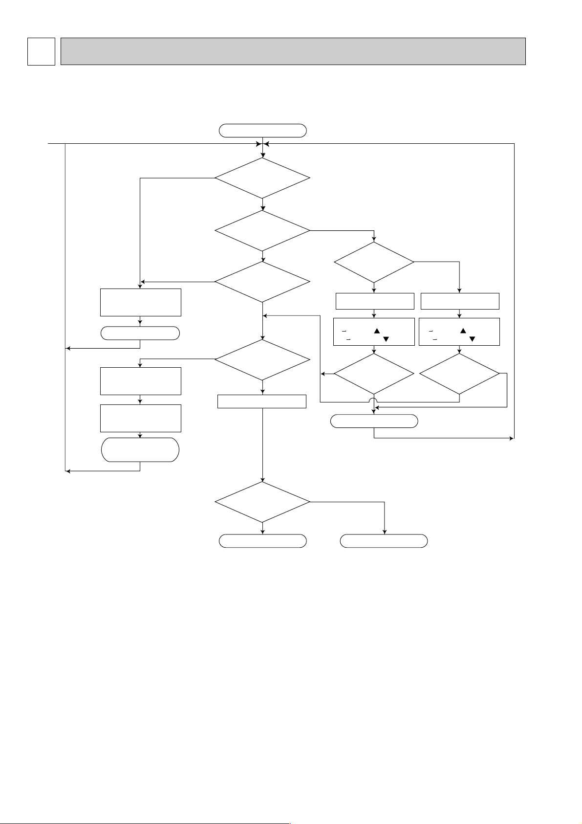
OPERATION FLOW-CHART8
1. Main operation
1
Start
POWER SUPPLY
Live
ON/OFF
button ON
TIMER MODE
button ON
During
operation
AUTO STOP lamp ON AUTO START lamp ON
Auto start timer
1 12Hr up/ press
12 1Hr down/ press
Abnormal
operation mode
MODE SELECT
button
EMERGENCY
ALL STOP
STOP
STOP
Self-diagnostic function
Indicate & Memory
Protection device
Self hold
Protection device
Self hold reset
COOL OPERATION
DRY OPERATION
POWER lamp ON
NO
NO
NO
NO
NO
NO
NO
DRY
COOL
YES
YES
YES YES
YES
YES
YES
<Note 1>
<Note 3>
<Note 2>
<Note 5>
<Note 4>
Auto stop timer
1 12Hr up/ press
12 1Hr down/ press
Set time Elapsed time=0
Set time Elapsed time=0
Note 1. Refer to page 22 for timer mode details.
Note 2. The unit starts operation by pressing the ON / OFF switch when unit is OFF.
During operation, the unit stops operation by pressing the ON / OFF switch.
In addition, operation can be turned ON / OFF with the contralized remote controller or the remote switch.
Note 3. The factors which cause "abnormal operation mode" are as follows.
●Outdoor unit abnormal operation.
●Fault of room temperature thermistor (RT1).
●Fault of indoor coil thermistor (RT2).
●Indoor coil frost protection mode.
●Drain water overflow prevention mode.
Refer to page 25 for abnormal operation mode details.
Note 4. The indoor fan runs on the low speed for 1 minute to eliminate remaining heat.
Note 5. The compressor will not start for 3 minutes after the stop.
Page 15

15
3-minute
time delay
Compressor start
3 minutes elapse
Compressor
start 10 minutes
elapse
Compressor
start 16 minutes
elapse
6-minute
time delay
Coil frost
protection
Coil frost
prevention
Indoor coil
temperature
1C or below
Indoor coil
temperature 10:
or more
3-minute time delay
Coil frost
prevention release
Coil frost
prevention set
Range C
Allowance release
Compressor ON Compressor OFF
NO
NO
NO
NO
NO
NO
NO
NO
NO
NO
YES
YES
YES
YES
YES
YES
YES
YES
YES
YES
YES
YES
YES
YES
NO
NO
NO
NO
COOL operation
<Note 6>
<Note 7>
<Note 8>
Compressor
thermostat ON
Allowance release
Allowance
Allowance set
6-minute time delay
Coil frost
protection
check mode
Continue
1 minute
Fan speed LOW
Fan speed LOW
5 minutes elapse
Outdoor unit abnor-
mality check mode
2. COOL operation
Note 6. The thermostat is continuously ON during the test run.
Note 7. Refer to page 18~19 for coil frost protection.
Note 8. Range A : Indoor coil temperature is more than 5 degrees above room temperature.
Range B : Indoor coil temperature is within 5 degrees either way of room temperature.
Range C : Indoor coil temperature is more than 5 degrees below room temperature.
Page 16

16
3. DRY operation
Note 9. When the room temperature is 18°C or below, the compressor can not turn ON. When the room temperature rises to
18°C or above, the compressor will start operation after a 3-minute time delay.
Note 10. Refer to page 20 for the compressor operation time.
Note 11. In DRY operation, the indoor fan runs on the low speed during the compressor ON and stops during the compressor
OFF.
YES
DRY operation
Room temperature
18 C or below
NO
Compressor ON
<Note 9>
NO
NO
10-minute timer start
YES
Compressor ON
3 min.elapse
YES
Compressor
thermostat ON
YES
Compressor ON
time completed
YES
Compressor OFF
Compressor OFF
<Note 11>
Fan stop
<Note 6>
NO
NO
YES
3-minute
time delay
NO
Compressor
thermostat ON
NO
Compressor OFF
10 minutes completed
YES
<Note 10>
Compressor ON
time set
YES
Compressor ON
<Note 11>
Fan speed LOW
YES
<Note 6>
NO
1
Page 17

17
MICROPROCESSOR CONTROL9
● OFF-ON switching.
● COOL/DRY-FAN selector switching.
● HIGH-LOW fan speed switching.
● Swing louvers SWING-FIXED switching.
● TIMER mode selector switching.
● Thermostat setting.
● Timer setting.
● Self diagnostic troubleshooting.
● Test run switching.
● Room temperature thermistor.
● Indoor coil thermistor.
● Drain sensor.
● Compressor protection device working
● Compressor motor and outdoor fan motor :
ON - OFF
● Fan : ON - OFF.
● Fan speed : HIGH - LOW
● Swing louvers : ON-OFF.
● Drain water lift-up mechanism : ON-OFF
● Emergency stop.
OUTPUT to indoor unit
INPUT from indoor unit
INPUT to remote controller
● Transmits and receives orders.
REMOTE CONTROLLER
OUTPUT to remote controller
INDOOR CONTROLLER BOARD
● Receives orders from remote controller and temperature data from
indoor unit.
● Processes orders and data.
● Transmits the power of indication LED to remote controller
● Controls indoor and outdoor operation.
● Self diagnostic function.
w System control operation.<Optional>
w Emergency operation.
12VDC
12VDC
Polar, twelve (12) - core cable
Maximum length 50m (164ft)
Non - polar, two (2) - core cable
12
Outdoor unit
● Indication LED lights.
Indoor unit
PL-KJC
OUTPUT to outdoor unit
INPUT from outdoor unit
OUTDOOR UNIT
● Receives order from indoor
controller.
● Emergency stop.
1.OUTLINE OF MICROPROCESSOR CONTROL
TIMER TEMP
TIMER/TEMP.
UP
DOWN
POWER
COOL
DRY
FAN
HIGH
LOW
ON
AUTO
STOP
START
MITSUBISHI ELECTRIC
29
12
28
11
27
10
26
9
25
8
24
7
23
6
22
5
21
4
20
3
19
2
18
1
ON/OFF
MODE
SELECT
FAN
SPEED
LOUVER
TIMER
MODE
Page 18

18
2. INDOOR UNIT CONTROL
2-1COOL operation
(1) Compressor control
1 3-minute time delay
To prevent overload, the compressor will not start within 3 minutes after stop.
2 The compressor runs when the room temperature is higher than the set temperature.
The compressor stops when the room temperature is equal to or lower than the set temperature.
3 The compressor stops in check mode or during protective functions.
4 Coil frost prevention
To prevent indoor coil frost, the compressor will stop when the indoor coil thermistor (RT2) reads 1°C or below after the
compressor has been continuously operated for 16 minutes or more. The coil frost prevention is released under any of the
following conditions.
● The indoor coil thermistor rises to 10°C or above.
● The room temperature becomes equal to or lower than the set temperature.
● COOL mode is stopped or changed to another mode.
NOTE : By cutting the jumper wire JRO2 on the indoor controller board, the temperature to start coil frost prevention
changes from 1°C to -3°C.
<How to operate>
1 Press POWER ON/OFF button.
2 Press MODE SELECT button to set operation mode to COOL.
3 Check lamp is ON and set desired temperature with UP
or DOWN button.
NOTES : 1. When lamp is ON, press TIMER/TEMP button
to change the display to temperature mode.
2. Set temperature changes by 1°C in the range 18 ~ 29°C
each time UP or DOWN button is pressed.
3. The lighting lamp shows the set temperature, and the
flashing lamp shows the room temperature.
When the room temperature is equal to the set
temperature, the lamp keeps lighting, 0.5 seconds
brightly and 0.5 seconds faintly.
TIMER
<COOL operation time chart>
w1 Even if the room temperature rise above the set temperature during this period, the compressor will not start until this
period has ended.
MITSUBISHI ELECTRIC
12
11
10
9
8
7
6
5
4
3
2
1
29
28
27
26
25
24
23
22
21
20
19
18
TIMER TEMP
TIMER/TEMP.
UP
DOWN
POWER
COOL
ON/OFF
LOUVER
MODE
SELECT
FAN
SPEED
TIMER
MODE
DRY
FAN
HIGH
LOW
ON
AUTO
STOP
START
Operation starts by
POWER button
ON.
ON
Thermostat
OFF
TEMP.
Room temperature
becomes equal to
set temperature.
Room temperature
rises above set
temperature.
Operation stops by
POWER button
OFF.
ON
LOW or HIGHLOW or HIGH
Indoor fan
Louver
OFF
ON
OFF
Depends on remote controller setting
ON
Drain pump
OFF
ON
Compressor
OFF
MIN. 3 minutes w1
3 minutes
Page 19

19
5 Coil frost protection
When indoor coil temperatuer becomes -15°C or below,coil frost protection will proceed as follows.
<Start condition>
After the compressor has been continuously operated for 3 minutes or more,and the indoor coil temperature has been 15°C or below for 3 minutes,the coil frost protection will start.
<Coil frost protection>
Compressor stops for 6 minutes,and then restarts.
lf the start condition is satisfied again during the first 10 minutes of compressor operation,both the indoor and outdoor
units stop, and the remote controller displays this occurrence.
<Termination conditions>
Coil frost protection is released when the start condition is not satisfied again during the allowance, or when the COOL
mode stops or changes to another mode.
(2) Indoor fan control
Indoor fan speed LOW/HIGH depends on the remote controller setting.
However, if an outdoor unit abnormality is detected, the indoor fan speed will be LOW, regardless of the remote controller
setting.
(3) Louver control
Louver operation (SWING LOUVER ON / OFF) depends on the remote controller setting.
(4) Detecting abnormalities in the outdoor unit
After the compressor has been continuously operated for 3 minutes, if the difference between the indoor coil temperature
and the room temperature is out of RANGE C for 1 minute, the indoor fan speed will turn to LOW. Five minutes later, if the
difference is still out of RANGE C,the outdoor unit is functioning abnormally. Thus, the compressor will stops and the
remote controller will display this occurrence.
RANGE A : Indoor coil temperature is more than 5 degrees above room temperature.
RANGE B : Indoor coil temperature is within 5 degrees either way of room temperature.
RANGE C : Indoor coil temperature is more than 5 degrees below room tempetature.
(5) Dew prevention heater
To prevent dew from accumulating on the grill, dew prevention heater is continuously ON in COOL or DRY operation.
It is independant of the thermostat ON/OFF
(6) Drain pump control
The drain pump works in COOL or DRY operation. When COOL or DRY operation stops or changes to another mode, the
drain pump continues to operate for 3 more minutes. Even if the check mode starts during COOL or DRY operation, the
drain pump continues to operate for 3 more minutes.
<Drain sensor>
When both the drain pump and the unit are operating, the drain sensor detects the temperature. This temperature tells
whether the drain water level is above or under the drain sensor. If the drain water levels rises above the drain sensor due
to a drain pump malfunction, the unit will enter the check mode. The operation will stop and only the drain pump will
continue to operate for 3 more minutes. When either of the following conditions are satisfied, the drain sensor is deemed
under water.
● Though the drain sensor has been heated by the drain sensor heater for more than 40 seconds, its temperature rise is
less than 20 degrees.
● The drain sensor temperature is below 63°C.
2-2 DRY operation
MITSUBISHI ELECTRIC
12
11
10
9
8
7
6
5
4
3
2
1
29
28
27
26
25
24
23
22
21
20
19
18
TIMER TEMP
TIMER/TEMP.
UP
DOWN
POWER
COOL
ON/OFF
LOUVER
MODE
SELECT
FAN
SPEED
TIMER
MODE
DRY
FAN
HIGH
LOW
ON
AUTO
STOP
START
<How to operate>
1 Press POWER ON/OFF button.
2 Press MODE SELECT button to set operation mode to DRY.
3 Check lamp is ON and set desired temperature with UP
or DOWN button.
NOTES : 1. When lamp is ON, press DISPLAY SELECT
button to change the display to temperature mode.
2. Set temperature changes by 1°C in the range 18 ~ 29°C
each time UP or DOWN button is pressed.
3. The lighting lamp shows the set temperature, and the
flashing lamp shows the room temperature.
When the room temperature is equal to the set
temperature, the lamp keeps lighting, 0.5 seconds
brightly and 0.5 seconds faintly.
TIMER
TEMP.
Page 20

20
<DRY operation time chart>
MIN. 3 minutes
w2
ON
Thermostat
Indoor fan
Louver
Drain pump
Compressor
ON
ON
LOW speedLOW speed
ON
OFF
OFF
ON
OFF
3 minutes
OFF
OFF
Operation starts by
POWER button
ON.
Operation stops by
POWER button
OFF.
Room temperature
becomes equal to
set temperature.
Room temperature
rises above set
temperature.
Depends on remote controller setting
w2 Even if the room temperature rises above the set temperature during this period, the compressor will not start
until this period has ended.
(1) Compressor control
13-minute time delay
To prevent overload, the compressor will not start within 3 minutes after stop.
2The compressor runs when the room temperature is higher than the set temperature.
The compressor stops when the room temperature is equal to or lower than the set temperature.
3The compressor stops in check mode or during protective functions.
4The compressor will not start when the room temperature is below 18°C.
The compressor starts intermittent operation when the power is turned ON with room temperature above 18°C. The
compressor ON/OFF time depends on the thermostat ON/OFF and the room temperatures as follows.
After 3-minute compressor operation,
● If the room temperature thermistor reads above 28°C with thermostat ON, the compressor will operate for 6 more
minutes and then stop for 3 minutes.
● If the room temperature thermistor reads 26°C~28°C with thermostat ON, the compressor will operate for 4 more
minutes and then stop for 3 minutes.
● If the room themperature thermistor reads 24°C~26°C with thermostat ON, the compressor will operate for 2 more
minutes and then stop for 3 minutes.
● If the room temperature thermistor reads below 24°C with thermostat ON, the compressor will stop for 3 minutes.
● If the thermostat is OFF regardless of room temperature, the compressor will stop for 10 minutes.
5Coil frost protection
Coil frost protection in DRY operation is the same as in COOL operation.
6Coil frost prevention
Coil frost prevention does not operate in DRY operation.
(2) Indoor fan control
The indoor fan runs on LOW speed during compressor operation. The fan speed cannot be changed with the remote
controller.
Also, the indoor fan does not run during compressor OFF.
(3) Louver & drain pump controls
Same as in COOL operation.
(4) Detecting abnormalities in the outdoor unit
An abnormality in the outdoor unit can not be detected in DRY operation.
Page 21

21
2-3 FAN operation
MITSUBISHI ELECTRIC
12
11
10
9
8
7
6
5
4
3
2
1
29
28
27
26
25
24
23
22
21
20
19
18
TIMER TEMP
TIMER/TEMP.
UP
DOWN
POWER
COOL
ON/OFF
LOUVER
MODE
SELECT
FAN
SPEED
TIMER
MODE
DRY
FAN
HIGH
LOW
ON
AUTO
STOP
START
<How to operate>
1 Press POWER ON/OFF button.
2 Press MODE SELECT button to set operation mode to FAN.
NOTE : Temperature can not be set in FAN operation.
1 Indoor fan control
The indoor fan speed LOW/HIGH depends on the remote controller setting.
2 Louver control
The louver operation ON/OFF depends on the remote controller setting.
3 Drain pump control does not work in FAN operation. As an exception, when COOL mode changes to FAN mode, the drain
pump continues to operate for the first 3 minutes in FAN operation.
Page 22

22
<Timer function>
AUTO STOP ·········Air conditioner stops after the set time lapses.
AUTO START ········Air conditioner starts after the set time lapses.
<How to operate
●
AUTO STOP timer>
1 While ● POWER I lamp is lighting, press TIMER MODE button.
■■■
STOP
and lamps turn ON.
2 Set the time for the AUTO STOP timer with the UP or DOWN button.
NOTE : The time setting is in 1 hour units up to 12 hours.
3 With the lapse of time, the timer lamps turn OFF one by one, showing
the remaining time.
4 To cancel the AUTO STOP timer and continue operation, press the
TIMER MODE button.
To cancel the AUTO STOP timer and stop operation, press the
POWER ON/OFF button.
<How to operate AUTO START timer>
1 While ❍ POWER I lamp is OFF, press TIMER MODE button.
■■■
START
and lamps turn ON.
2 Set the time for the AUTO START timer with the UP or DOWN button.
NOTE : The time setting is in 1 hour units up to 12 hours.
3 With the lapse of time, the timer lamps turn OFF one by one, showing
the remaining time.
4 To cancel the AUTO START timer and keep the unit OFF, press the
TIMER MODE button.
To cancel the AUTO START timer and start operation, press the
POWER ON/OFF button.
TIMER
2-4 TIMER operation
MITSUBISHI ELECTRIC
12
11
10
9
8
7
6
5
4
3
2
1
29
28
27
26
25
24
23
22
21
20
19
18
TIMER TEMP
TIMER/TEMP.
UP
DOWN
POWER
COOL
ON/OFF
LOUVER
MODE
SELECT
FAN
SPEED
TIMER
MODE
DRY
FAN
HIGH
LOW
ON
AUTO
STOP
START
12
11
10
9
8
7
6
5
4
3
2
1
29
28
27
26
25
24
23
22
21
20
19
18
Green
lamps
Remaining time:2 hour
59 minutes to 2 hour
TIMER TEMP.
12
11
10
9
8
7
6
5
4
3
2
1
29
28
27
26
25
24
23
22
21
20
19
18
1 hour 59 minutes
to 1 hour
TIMER TEMP.
12
11
10
9
8
7
6
5
4
3
2
1
29
28
27
26
25
24
23
22
21
20
19
18
59 minutes to 0
12
11
10
9
8
7
6
5
4
3
2
1
29
28
27
26
25
24
23
22
21
20
19
18
Time counting
is completed.
TIMER TEMP. TIMER TEMP.
<Remaining time display>
NOTE : When AUTO STOP timer is active, the remaining time display can be changed to the temperature display by pressing
DISPLAY button.
AUTO
AUTO
The green lamps show the remaining time until the time is up. When the time is up, the green lamps are all off.
I
TIMER TEMP.
TIMER
Page 23

23
2-5 Test run
The unit starts the test run by pressing both the UP and DOWN buttons simultaneously for more than two seconds
during lamp ON or the unit OFF.
● The test run automatically stops in 2 hours.
● Set temperature is not displayed during test run.
● To cancel the test run, press the POWER ON/OFF button.
<Initial setting>
The units are set as follows by the factory.
1) Initial operation mode: FAN 3) Swing louver :OFF
2) Fan speed : LOW 4) Set temperature : 28°C
2-6 Emergency operation
When the remote controller or microprocessor malfunctions and
no other trouble exists, emergency operation is available by
setting the dipswitch on the indoor controller board.
[Check items]
1 Make sure the compressor and the fans are running normally.
2 Locate the trouble with the self-doagnostic function. If the self-
doagnostic function indicates that the protection device (such
as coil frost protection)is functioning, the sources must be
removed before attempting emergency operation.
Emergency operation ON/OFF is activated not with the remote
controller but with the circuit breaker.
[Emergency operation procedure]
1 Cooling operation is available by setting the dipswitch SW3
1and 2 ON and 3 OFF on the indoor controller board.
2 To start emergency operation, turn the outdoor side circuit
breaker ON first, and then the indoor side circuit breaker ON.
3 During emergency operation, the indoor fan runs on HIGH
speed, the compressor runs continuously, and the louver stops.
When the drain pump is attached, it works in emergency
operation.
4 Thermostat will not function.
5 Do not use emergency cooling operation for more than 10
hours, as the indoor coil may freeze.
w If the self-diagnostic function shows a drain pump malfunction,
do not attempt emergency operation, as the drain may overflow.
2-7 Auto Restart function
Unit can be start / stop by turning the breaker ON / OFF.
1) Cutting the JR06 on the indoor board.
Unit can be start / stop using the remote controller. Only in case the unit was operated before a power cut, the unit will
restart automatically after power is back.
2) Short all the CN2 on the indoor board.
Unit can not be start / stop using remote controller.
Unit will restart automatically whether the unit was operated or stopped when the power was cut off.
INDOOR CONTROLLER BOARD
TIMER
SW3
JR06
Original
Cut
Auto restart
Not available
Available
1
2
3
CN2
ORN
BRN
RED
Optional timer adapter
PAC-SA89TA-E
Page 24

2-8 Function of jumper wire and dipswitch on indoor controller board
1. Jumper wire
1 JR01
...
Jumper wire for the auto vanes.
Cut JR01 for the unit WITHOUT auto vanes.
2 JR02
...
Jumper wire for the temperature to start coil frost prevention
Cutting JR02 changes the temperature from +1°C to -3°C.
3 JR03
...
Jumper wire for set temperature adjustment in HEAT mode.
In HEAT operation, heated air stagnates in the upper part of the room. The indoor unit installed in the upper part of the
room will detect the air temperature higher than the actual temperature in the living space. This difference is about 4
degrees. Therefore, the temperature detected by the room temperature thermistor should be corrected 4 degrees down.
The unit with JR04 attached will make this adjustment.
4 JR04
...
Jumper wire for the indoor fan speed during thermostat OFF in HEAT mode
Cutting JR04 changes the speed from Extra-Low to Low.
5 JR05
...
Jumper wire for detecting abnormalities in the outdoor unit
Cutting JR05 makes this detection unavailable. (Occurrence of abnormality can not be detected. )
6 JR06
...
Jumper wire for auto restart function
Cutting JR06 makes the auto restart function available.
2. Dipswitch
1 SW1 (Function switch)
SW1-1) Switch for power supply
ON : 220V
OFF : 230V, 240V
SW1-2) Switch for single or twin control
ON : Twin control
OFF : Single control
SW1-3) Switch for unit number in twin control (This switch is valid when SW1-2 is ON. )
ON : Unit No. 2
OFF : Unit No. 1
SW1-4~SW1-6 Switch for capacity of each model
SW1-7, SW1-8 Switch for the pair number of wireless remote controller
2 SW2 (Unit switch)
SW2-1) Switch for air conditioner with or without electric heater
ON : Unit with electric heater
OFF: Unit without electric heater
SW2-2) Switch for air conditioner with or without heat pump
ON : Unit with heat pump
OFF: Unit without heat pump
SW2-3, SW2-4) Switch for function code
3 SW3 (Emergency operation switch)
Normal operation
24
1 2 3 4 5 6 7 8
ON
OFF
1 2 3 4 5
ON
OFF
PL-1.6KJC PL-2KJC PL-2.5KJC
4 5 6
ON
OFF
PL-KJC
3 4 5
ON
OFF
0
7 8
ON
OFF
1
7 8
ON
OFF
2
7 8
ON
OFF
3
7 8
ON
OFF
4 5 6
ON
OFF
4 5 6
ON
OFF
1 2 3
ON
OFF
4 SWA : for ceiling height
3
...
High ceiling
2
...
Standard
3
...
Silent
5 SWB : for number of air outlets
2
...
(Unavailable)
3
...
3 directions
4
...
4 directions
6 SWC : optional filter element
STD
...
Without filter element
OP
...
With filter element
For emergency cooling
1 2 3
ON
OFF
4-directional
3-directional
SWB
SWA
2.4m
2.7m
Silent Standard High ceiling
2.7m
3.0m
3.0m
3.3m
Page 25

25
10
TROUBLESHOOTING
1. SELF-DIAGNOSTIC FUNCTION
! When trouble occurs during operation, the unit stops and enters the self-diagnostic mode, and displays the trouble
location with the timer lamps on the remote controller. All the other lamps are OFF.
@ To activate the self-diagnostic function for service, press the UP and DOWN buttons simultaneously for more than two
seconds during operation with lamp ON.
# The timer lamps show the latest trouble. Trouble data is memorized until the next trouble occurs, even when the breaker
turns OFF. To clear the memory, press the UP and DOWN buttons simultaneously for more than two seconds during the
test run.
$ All buttons except the POWER ON/OFF button are unavailable during the self-diagnostic mode.
% To release the self-diagnostic mode, press the POWER ON/OFF button.
TEMP.
Unit
Trouble location
Transmission error
in twin control
Cause
● Wrong wiring between No. 1
and No. 2 units
● Poor connector contact
Measures
● Check dipswitch setting
● Check wiring
Outdoor unit
● Wrong wiring between
indoor/outdoor units
● Outdoor unit abnormality
detection
● Malfunction of outdoor coil
thermistor
● Reversed phase detected
● Check wiring
● Check outdoor unit
● Check outdoor coil thermistor
Unit
No.1
Unit
No.2
Room
temperature
thermistor
(RT1)
● Poor connector contact
● Thermistor malfunction
● Check connector
● Check thermistor
➔ No trouble ➔ replace indoor
controller
board.
Unit
No.1
Unit
No.2
Indoor coil
thermistor
(RT2)
● Poor connector contact
● Thermistor malfunction
● Check connector
● Check thermistor
➔ No trouble ➔ replace indoor
controller
board.
Unit
No.1
Unit
No.2
Drain sensor
(DS)
● Poor connector contact
● Thermistor malfunction
● Check connector
● Check thermistor
➔ No trouble ➔ replace indoor
controller
board.
Unit
No.1
Unit
No.2
Drain
overflow
protection
● Drain pump malfunction
● Drain sensor improperly
mounted
● Check drain pump
● Check drain sensor
➔ No trouble ➔ replace indoor
controller
board.
Unit
No.1
Unit
No.2
Coil frost
or overheat
prevention
● Air passage short cycle
● Air filter clogged
● Indoor fan malfunction
● Remove blockage
● Check air filter
● Check indoor fan
12
11
10
9
8
7
6
5
1
2
3
4
(Indicates that the unit is in self-diagnostic mode)
TIMER TEMP.
}
}
}
}
28
27
26
25
24
23
22
18
19
20
21
29
Page 26

26
Louvers do not work.
Louvers motor does not work.
Connector is poorly connected.
Louvers is poorly assembled.
Indoor controller board is damaged.
Unit stops after 5 to
20 seconds operation
Protection function is working.
Power ON/OFF button
does not work.
Indoor/outdoor
connecting wire is
connected incorrectly.
Indoor/outdoor
connecting wire shorts.
Compressor protector is
damaged.
Deicer is broken.
Remote controller is
damaged.
Transmission wire is
poorly connected
Transmission wire is
damaged.
Connector is poorly
connected.
Louvers motor is damaged.
Louvers motor relay is damaged.
Refer to check code on remote controller display.
2. OTHER TROUBLES AND CAUSES
Page 27

27
4-WAY AIR FLOW SYSTEM
11
1.Placement of the air outlets
●For this grill, the airflow direction comes in 5 patterns.
Also, by setting the dipswitches (SWA and SWB)on the indoor board to the appropriate settings, you can adjust the air flow
and speed. Select the settings that are needed from those in Tables 2 and 3 according to the place where you want to install
the unit.
1) Decide on the pattern of the discharge direction.
4-direction 3-direction
Airflow direction
pattern
Pattern 1 Pattern 4
Factory setting
One air outlet
fully closed
2) According to the number of air outlets and the height of the ceiling to install the unit, be sure to set the dip switches
(SWA, SWB, SWC) on the indoor board to the appropriate setting.
<Initial setting by factory>
SWA : for ceiling height SWB : for number of air outlets SWC : optional filter element
3···High ceiling 2···(Unavailable) STD···Without filter element
2···Standard 3···3 directions OP···With filter element
1···Silent 4···4 directions
<Table 1>
<Table 2>
Silent
4-directional
2.4m
2.7m 3.0m
3-directional 2.7m 3.0m 3.3m
Standard High ceiling
SWB
SWA
Note 1. For the 3-direction airflow, install the air outlet
shutter plate(PAC-SE14SP-E)
Note 2. The 2-direction airflow is unavailable.
2.Installing the outlet shutter plate (PAC-SF38SP-E)
For the 3-direction discharge, close one air outlet fully by installing the air outlet shutter plate before installing the grill.
<Caution> Installing the shutter plate not securely will cause air leak and water dripping.
<How to attach the shutter plate>
Peel off the separation sheet from the shutter plate, and attach the shutter plate to the air outlet of the indoor unit.
Indoor unit
Shutter plate
Page 28

28
DISASSEMBLY PROCEDURE
12
Be careful on removing heavy parts.
OPERATING PROCEDURE PHOTOS&ILLUSTRATIONS
1. Removing the air intake grill
(1) Press the button.
(2) Open the intake grill 90°.
(3) Remove the clip.
(4) Slide the shaft in the hinge to the left and remove the
intake grill.
PUSH
3. Removing the fan motor
(1) Remove the turbo-fan nut and radiator aluminum cap.
(2) Pull out the turbo fan.
(3) Disconnect the connector of the fan motor lead wire.
(4) Remove the 3nuts of fan motor.
3. Removing the electrical parts box
(1) Disconnect the lead wire of the vane motor from the clamp,
and disconnect the red connector (8P).
(2) Remove 2 of 4 screws from the electorical parts cover.
(3) Remove the electorical parts cover.
(4) Disconnect the following connectors from the box.
Red (3P) for the fan motor
White (2P) for the indoor coil trermistor
Blue (2P) for the drain pump
White (4P) for the drain sensor
(5) Disconnect the green anti-falling wire of the electrical parts
box.
(6) Remove 3 of 4 screws from the electrical parts box, and
loosen the other screw.
(7) Pull out the electrical parts box.
Electrical parts inside the box
Terminal block
Transfomer
Indoor fan capacitor
Room temperature thermistor
Indoor controller board
Figure 1
Photo 3
nut
Fan motorConnector
Photo 1
Photo 2
Screws
Connector
Fan guard
Fan guard screw
Terminal block
Transformer
Connector
Capacitor
Nut
Readiator alumium
cap
Anti-failing
wire
Room
temparature
thermistor
Electrical box
Indoor
controller
board
PUSH button
Shaft
Intake grill
Page 29

29
OPERATING PROCEDURE PHOTOS&ILLUSTRATIONS
4. Removing the room temperature thermistor
(1) Remove the electrical box cover
(2) Remove the holder and the room temperature thermistor
by pulling the catch.
(3) Disconnect the red connector,CN20,on the indoor
controller board.
5. Removing the indoor coil thermistor
(1) Remove the electrical box cover.
(2) Remove the electrical box.
(3) Remove the turbo fan.
(4) Remove the screw of the service panel.
(5) Remove the service panel.
(6) Remove the indoor coil thermistor from the holder
attached to the copper pipe.
(7) Disconnect the 2-pin white connector.
6. Removing the panel
(1) Open the intake grill.
(2) Disconnect the connector of the vane motor.
(3) Remove 4 screws of the panel.
(4) Pulling the temporary handing hook, remove the panel.
7. Removing the drain pan
(1) Remove the panel.
(2) Remove the rubber bushing.
(3) Drain the remaining water in the drain pan.
(4) Remove the electrical box cover.
(5) Remove the electrical box.
(6) Refmove the screw of the V.A. cover, and remove the V.A.
cover.
(7) Remove each screw of the corner supports 1,2, and 3,
and remove the corner supports 1,2 and 3.
(8) Pull out the drain pan.
wPull the left and right of the pan gradually.
Be careful not to crack or damage the pan.
Photo 7
Photo 6
Photo 5
Photo 4
Indoor controller board
Room
temparature
thermistor
Mounting hole
Indoor coil thermistor
Screws
Screws
Panel
Temporary hanging hook
Temporary
hanging hook
Screws
Coner cover
screws
Coner cover
Screws
Screws
Drain
pan
Page 30

30
OPERATING PROCEDURE PHOTOS&ILLUSTRATIONS
8. Removing the drain pump and drain sensor
(1) Remove the panel.
(2) Remove the electrical parts cover.
(3) Remove the electrical parts box.
(4) Remove the drain pan.
(5) Remove 4 screws of the drain pump.
(6) Pulling the clip of the drain hose, pull out the drain hose
from the drain pump.
(7) Remove the drain senser and the holder.
(8) Pull out the drain pump.
9. Removing the heat exchanger
(1) Remove the panel.
(2) Remove the electrical parts cover.
(3) Remove the electrical parts box.
(4) Remove the drain pan.
(5) Remove the turbo fan.
(6) Remove the screw of the coil support A.
(7) Remove the 2 screws of the coil support B.
(6) Remove the 2 screws of the coil.
(8) Remove 4 screws of the piping cover of the outer wall,
and pull out the piping cover.
Photo 9
Photo 10
Photo 11
Screws
Drain senser
holder
Drain
pump
Clip
Drain
hose
Screw of the coil
support A
Heat
exchanger
Coil set screws
Coil
support
A
Screw
Piping cover
Screw
Page 31

31
PARTS LIST13
No.
Parts No. Parts Name Specifications
Wiring
Diagram
Symbol
Recom-
mended
Q'ty
Unit
Amount
Q'ty / set
PL-1.6/2/2.5
KJC
Price
1
2
3
4
5
6
7
AIR OUTLET GRILLE
AIR FILTER
INTAKE GRILLE
HINGE
GRILLE HANGER
REMOTE CONTROLLER
REMOTE CONTROLLER CABLE
1
1
1
2
1
1
1
(BG88H096H01)
R.B
12m
Remarks
(Drawing No.)
T7W 560 003
R01 29H 500
R01 29H 691
R01 29H 061
–
T7W 20K 200
T7W 139 305
PANEL PARTS
PL-1.6KJC
PL-2KJC
PL-2.5KJC
7
Page 32

32
FUNCTIONAL PARTS
PL-1.6KJC
PL-2KJC
PL-2.5KJC
Page 33

33
No.
Parts No. Parts Name Specifications
PL-1.6/2/2.5
KJC
Wiring
Diagram
Symbol
Recom-
mended
Q'ty
Unit
Amount
Q'ty / set Price
Part numbers that are circled not shown in the figure.
1
2
3
4
5
6
7
8
9
10
11
12
13
14
15
16
17
18
19
20
21
22
23
24
25
26
27
28
29
30
31
32
33
34
BASE
LEG
LEG
LEG
LEG
INDOOR FAN MOTOR
MOTOR MOUNT
INNER COVER
TURBO FAN
INDOOR COIL THERMISTOR
DRAIN SOCKET
DRAIN PUMP
DRAIN SENSOR
DRAIN HOSE
HEAT EXCHANGER
HEAT EXCHANGER
HEAT EXCHANGER
DRAIN PAN
CORNER COVER
COVER (DRAM)
TERMINAL BLOCK
TERMINAL BLOCK
INDOOR FAN CAPACITOR
CONTROLLER CASE
INDOOR CONTROLLER BOARD
FUSE
TRANSFORMER
ROOM TEMPERATURE
THERMISTOR
BELL MOUTH
ELECTRICAL PARTS COVER
SPL WASHER
DRAIN PLUG
FAN GUARD
SENSOR HOLDER
CORE
CORE
CABEL FOR BOARD
1
1
1
1
1
1
3
1
1
1
1
1
1
1
1
1
1
1
1
1
1
1
1
1
1
1
1
1
1
1
1
1
2
1
1
1
1
1
1
1
1
3
1
1
1
1
1
1
1
1
1
1
1
1
1
1
1
1
1
1
1
1
1
1
1
1
1
2
1
1
1
1
1
1
1
1
3
1
1
1
1
1
1
1
1
1
1
1
1
1
1
1
1
1
1
1
1
1
1
1
1
1
2
1
1
(BG02Y348G06)
(BG00T672G08)
(BG00T672G09)
(BG00T672G10)
(BG00T673G02)
(BG00T718G05)
(BG00T713G05)
(BG00T712G06)
(BG25J542H04)
(BG00L601G22)
(BG00A662G18)
MF1
RT2
DP
DS
TB2
TB4
C1
I.B
F(I.B)
T
RT1
3P(L,N,;)
2P(1,2)
2.5+ 400V
250V 6.3A
Remarks
(Drawing No.)
–
–
–
–
–
T7W E00 762
R01 29H 105
–
R01 41N 114
R01 08K 202
R01 41N 523
T7W E00 355
R01 W28 266
R01 W28 527
T7W E03 480
T7W E04 480
T7W E05 480
T7W E00 529
–
–
T7W 521 716
T7W 512 716
R01 29H 255
–
T7W 27K 310
T7W 520 239
T7W 11K 799
R01 13A 202
–
–
R01 08K 097
R01 A48 524
T7W 29H 675
R01 71N 241
T7W E00 249
T7W E01 249
T7W 022 304
Page 34

34
PANEL PARTS
PL-1.6KJC
PL-2KJC
PL-2.5KJC
No.
Parts No. Parts Name Specifications
1
R01 29H 002
2
R01 29H 085
3
R01 29H 223
4
R01 29H 063
5
T7W 33K 063
6
R01 29H 056
7
R01 29H 047
8
T7W 560 258
9
R01 29H 040
10
R01 29H 041
AUTO VANE
AIR GUIDE
VANE MOTOR
SPRING JOINT 1
SPRING JOINT
PUSH BUTTON
VANE SUPPORT
CORD HEATER
GRILLE GEAR(RIGHT)
GRILLE GEAR(LEFT)
Q'ty / set
PL-1.6/2/2.5
KJC
4
1
1
1
1
1
8
1
1
1
Remarks
<3/SET>
Wiring
Diagram
Symbol
MV
H240V 28.2W
Recommended
Q'ty
Unit
Price
Amount
Page 35

35
14
OPTIONAL PARTS
Note 1. How to connect refrigerant pipes.
Factory supplied optional refrigerant piping contains refrigerant at the above atmospheric pressure. As long as
connection takes no more than 5 minutes, no air will enter, and there will be no need for air purging.
Remove the blind caps and make the connections within 5 minutes. After the connections for the indoor and outdoor
units are made, open the stop valve on the outdoor unit to allow refrigerant gas to flow.
If piping length exceeds 5m, an additional charge of refrigerant is needed.
Note 2. The following main parts are cntained in the optional refrigerant piping kit.
Heat insulating cover, vinyl tapes, nipples, sleeve and flange (for wall hole), connecting cables.
1. REFRIGERANT PIPES
Service Ref. : PL-1.6KJC / PL-2KJC / PL-2.5KJC
2. REMOTE CONTROLLER EXTENSION CABLE
When installing the remote controller at a distance from the air conditioner, use the designated extension cable with
connector.
3. TIMER
3-1 Specifications
(The PAC-815PT with the PAC - 825AD.)
Part No.
Pipe length
Pipe size O.D.
Connection method
PAC-05FFS-E
5m
Liquid:ø9.52
Indoor unit:Flared
Gas:ø15.88
Outdoor unit:Flared
PAC-07FFS-E
7m
PAC-10FFS-E
10m
PAC-15FFS-E
15m
Part No.
length
PAC-905EC
12m
PAC-906EC
20m
PAC-918EC
30m
PAC-919EC
50m
Part No.
Model Name
PAC-SK65PT
Program timer
Product name
Model name
Mounting method
Clock system
Clock accuracy
Display
Program cycle
Timer setting unit
Numbers of setting points
Minimum ON/OFF interval
Power failure safeguard
Rated power supply
Setback function
Program timer
PAC-SK65PT
Wall mounting
Quartz clock
±50 seconds/month
Time Liquid crystal display
Week Liquid crystal display
Timers setting Liquid crystal display
24 hours
30 minutes
48 /Day
–
–
5V DC
Provided
Page 36

36
3-3. How to connect program timer
(1) Install the program timer next to the remote controller the same way as the remote controller is installed.
(2) Connect the program timer and the remote controller with a 6-wire cable as shown in the figure below
NOTE : While the program timer is connected to the remote controller, the
24-hour ON/OFF timer on the remote controller will not operate.
3-2 Feature of program timer
(1) Daily timer function
Daily timer can be set in 30 minute units up to 24 hours.
Each unit can be set for unit ON, unit OFF, or setback operation.
(2) Setback operation.
Set back operation is useful for reducing running costs
Example : At a hotel with a 24-hour system
8:00~23:00 Cooling operation with set temperature at 26°C
23:00~8:00 Setback operation with 2 degrees of setback
As shown in the chart on the right, the set temperature rises 2 degrees
automatically during the setback operation. When the setback operation
ends, normal operation will begin.
(3) Weekly timer function
Daily timer function can apply to each day of the week.
28˚C
26
˚C
8:00
Normal
operation
23:00
Setback
operation
8:00
Normal
operation
MITSUBISHI ELECTRIC
SET MONITOR
BACK
ON OFF
ON OFF
AHEAD
BACK
AHEAD
Mode selector button : Use this button to select "MONITOR" or
"SET" mode.
"MONITOR" : Indicates the current timer setting. All buttons except
SET/MONITOR will not work in this mode. This is the
normal status.
"SET" : Set to "SET" mode for clock adjustment, change of day, daily
and weekly timer setting.
Clock adjustment button : Used to adjust the current time. Press AHEAD
button to advance the time. Each time the button is
pressed the time advances by 1 minute, and
pressing continuously advances 1 minute at a 0. 5
second interval. When the lower digit of the minutes
becomes 0, the indication advances in 10 minute
units. BACK button is used for reversing the time.
Each time the button is pressed the time reverses by
1 minute, and pressing continuously reverses the
time by 1 minute at a 0. 5 second interval. When the
lower digit of the minute becomes 0, the indication
reverses in 10 minutes units.
Weekday setting button : Used to set the day of the week.
Pressing button changes the day.
light displays in the order of S M T W.
Weekly timer button : Used to set the weekly timer.
Set back button : Used to set the set back amount. Set back can be set in the range of 1
to 9°C in 1°C unit.
Daily timer button : Used to set the daily timer in 30 minute units.
▼
Mode display
Current time
display
Weekly timer
display
Daily timer display
NOTE : display above is
only an example.
Current day
display
3-4. Names and functions
<PAC-SK65PT>
2-wire cable
Remote
controller
Connector CN1 Connector CN1
To indoor unit
Program
timer
5-wire cable
Page 37

37
4. CENTRALIZED REMOTE CONTROLLER
Allows individual or combined control of up to 16 units.
Part No. PAC-805RC
4-1. Dimensions
4-2. Names and Functions
"ENGAGED" indicator
When this indicator is lit, transmission is in
progress and all switches are inoperative.
DUAL/CENTRAL switch
This change-over switch governs the
operation of the accessory remote
controller.
"DUAL"
Instructions from both the accessory
remote controller and the centralized
remote controller are valid. (Priority is
given to the last instruction received.)
"CENTRAL"
ON/OFF switching by the accessory
remote controller is invalidated. Operation
is controlled by the centralized remote
controller only.
Initial setting is "DUAL".
LCD Matrix Display
This display indicates the operational
status of all connected units either by
steady lighting or by flashing.
POWER ON/OFF switch
Operation ON/OFF switch.
▲BACK ▼AHEAD buttons
These buttons are used to designate
the attached unit(s). (They designate
the unit to be centrally controlled.)
●When group “00” is designated;
collective ON/OFF instruction is sent to
all units.
●When group “01”-“16“ is designated;
ON/OFF instruction is sent only to the
designated units.
ACTIVE/BYPASS switch
This change-over switch for the
program timer.
Use “ACTIVE” when a program timer is
connected.
Use “BYPASS” when a program timer
is not connected.
Independent “DUAL / CENTRAL” and “ACTIVE / BYPASS” setting of all the groups is possible. When power supply to the
centralized remote controller is cut, due to a power failure, for example all settings return to original “DUAL” and “BYPASS”.
Unit : mm
12
113
23.5
56.3
11
ENGAGED
GROUP
12345678910
ACTIVE BYPASS
DUAL CENTRAL
GROUP
SELECTION
PROGRAM
TIMER
CONTROLLER
OPERATION
117
POWER
ON/OFF
AHEAD
BACK
ACTIVE
BYPASS
DUAL
CENTRAL
MITSUBISHI ELECTRIC
117
ENGAGED
GROUP
12345678910
ACTIVE BYPASS
DUAL CENTRAL
ENGAGED
GROUP
12345678910
ACTIVE BYPASS
DUAL CENTRAL
GROUP
SELECTION
PROGRAM
TIMER
CONTROLLER
OPERATION
GROUP
BACK
SELECTION
PROGRAM
ACTIVE
TIMER
BYPASS
DUAL
CONTROLLER
CENTRAL
OPERATION
10 9 8 7 6 5 4 3 2 1
POWER
ON/OFF
AHEAD
BACK
ACTIVE
BYPASS
DUAL
CENTRAL
MITSUBISHI ELECTRIC
POWER
ON/OFF
AHEAD
8
113
Page 38

38
TERMINAL-BLOCK
FOR TRANSMISSION
TERMINAL-BLOCK
OF POWER SUPPLY
Tie-lap
TRANSFORMER
Fuse(5A)
Tle-lap
ANE
Transmission
(W) (BN) (R) (O) (Y)
T
200
220
230
240
5A
A
N
E
POWER
SUPPLY
Wiring has to be change when
a 200,230 or 240 power is used.
BACK
ACTIVE
BYPASS
POWER
ON/OFF
DUAL
CENTRAL
AHEAD
ENGAGED
GROUP
ACTIVE BYPASS
GROUP
SELECTION
PROGRAM
TIMER
CONTROLLER
OPERATION
DUAL CENTRAL
12345678910
10 9 8 7 6 5 4 3 2 1
To adaptor's
terminal-block
Centralized remote
controller
Non-polar,
two-wire cable
To adaptor's
terminal-block
Power supply board box
BACK
ACTIVE
BYPASS
POWER
ON/OFF
DUAL
CENTRAL
AHEAD
ENGAGED
GROUP
ACTIVE BYPASS
GROUP
SELECTION
PROGRAM
TIMER
CONTROLLER
OPERATION
DUAL CENTRAL
12345678910
10 9 8 7 6 5 4 3 2 1
Dip switch
SW17
Centralized
remote controller
Power supply
board
4-3 Connection method
(1) Connections in the power supply cord.
1. Connect the power supply cord to the power supply terminal-block and fix it in-place with a tie-lap.
Connect a single phase 200V AC (220, 230, 240V) to .
As is the GND terminal, be sure to ground the earth wire.
2. Connect the transmission line to the transmission terminal-block and fix it in-place with a tie-lap.
Use a 1.6 (AWG 14) or above two-wire cable for the transmission line.
CAUTION : Never connect the power supply cord to the transmission terminal-block.
(2) Connection method of centralized remote controller and power supply board.
1. Connect the centralized remote controller and power supply board with a non-polar, two-wire cable.
2. Wiring diagram 3. Set the max. address number with the dipswitch SW17
of the centralized remote controller.
A N
E
Page 39

39
5. PROGRAM TIMER ADAPTER
This adapter is needed when a program timer(PAC-815PT)or the centralized remote controller(PAC-805RC)is used.
5-2 Connection method
Connection and wiring methods differ with the type of the indoor unit used. Confirm the type before carrying out the work.
5-1 Parts included
Part No. PAC-825AD
➀ ADAPTER·························1P ➁ 3-core cable ··························1P
➃ 4-core cable ··························1P
➂ 3-core cable ··························1P
➄ 5-core cable ··························1P
(1) Connections in the adapter Box
1. Connect the power supply cord to the terminal-block and fix it in-place with a tie-lap.
Connect a single phase 200V (220, 230, 240V) AC to .
As is the GND terminal, be sure to ground the earth wire.
2. Connect the transmission line to the transmission terminal-block and fix it in-place with a tie-lap, when a
centralized remote controller is being used.
CAUTION : Never connect the power supply cord to the transmission terminal-block
E
A N
Length : 2m (6' 7") Length : 2m (6' 7")
Length : 2m (6' 7") Length : 2m (6' 7")
Wiring has to be changed when 200V power supply is used.
fig.1fig
TERMINAL BLOCK
FOR
TRANSMISSION
CN22
Dip switch
SW1
2
.
CN22
TRANS
SW1
Tie-lap
Transmission cord
TRANS CN1 CN21 CN51 CN30 CN42 CN50 CN40
(AG)
ANE
Fuse(5A)
TRANSFORMER
200
220
-240
T
5A
A
N
E
TERMINAL BLOCK
FOR POWER
SUPPLY
Transmission
Tie-lap
(W) (B) (Y)
POWER SUPPLY CORD
POWER
SUPLLY
Page 40

40
2. Set the address number (from SW1-1 to SW1-6) in
the dipswitch when a centralized remote controller is
being used.
The address is the control number of each unit in the
centralized control system.
As the address serves as a time-delay device as
well, sequential starts (all units are triggered
collectively by one single ON instruction)must be set
with different address numbers (greater than 0) for
each adapter.
6. TIMER ADAPTER
This adapter is needed for system control and for operation via external contacts.
Adaptor
200~240V AC
3-core cable 5-core cable
52
To program timer or
centralized remote
controller
Fig.3
CN30 CN50
CN51CN2
Remote controller Indoor unit
Max. length of each cable is 10m.
65
230
22
15 15
86 70
35
27
15
hole
40 80 40 27
18
Fixing screw hole
4- 5.5
95
220
22
35
120
12
30
200
2 2 2.9
74
7
8
Fig. 4
ON
SW1
Levers No. 1-6 can set the following addresses respectively
with binary notations.
Address
Toggle
32
No.6 ON16No.5 ON8No.4 ON4No.3 ON2No.2 ON1No.1 ON
10
987654321
ON
10
987654321
ON
10
987654321
ON
10
987654321
(Ex.1) 3 = 2 + 1 (Ex.2) 9 = 8 + 1 (Ex.3) 15 = 8 + 4 + 2 + 1
Part No. PAC-SA89TA-E
@ Connection from adaptor 4. Dimensions
ORN 1
2
3
BRN
RED
Page 41

41
7. REMOTE INDICATION ADAPTER
This adapter is used for remote indication (operation / check) .
Part No. PAC-559AD
BRN
RED
<Wiring>
CN51
connector (5P)
BRN
RED
ORN
YLW
GRN
JST
XHP-3
5
1
Optional multiple display
adapter
The maximum distance between
indoor board and relay is 10m.
GREEN
YELLOW
ORANGE
RED
BROWN
X1
X2
Electrical insulation is needed.
Wiring at the actual place
ORN
YLW
5
5
2
X1
X2
GRN
RL
GL
Power
supply
Page 42

42
Part No. PAC-SE01AS-E
Applied Model PL-1.6KJC / PL-2KJC / PL-2.5KJC
8. SPACE PANEL
Part No. PAC-SE06WP-E
Applied Model PL-1.6KJC / PL-2KJC / PL-2.5KJC
9. WIDE PANEL
Part No. PAC-SF38SP-E
Applied Model PL-1.6KJC / PL-2KJC / PL-2.5KJC
10. AIR OUTLET SHUTTER PLATE
750
Hole
16
R7.8
R26
750
R
26
R7.8
965
Hole
965
R25
R37
R
6
R31
R25
R37
R
6
R31
R18047.5
R18102.5
440
122 99
65
42
13
Page 43

43
Part No. PAC-SE21TM-E
Applied Model PL-1.6KJC / PL-2KJC / PL-2.5KJC
11. MULTI-FUNCTIONAL CASEMENT
Part No. PAC-SE13KF-E
Applied Model PL-1.6KJC / PL-2KJC / PL-2.5KJC
12. HIGH-EFICIENCY FILTER ELEMENT
Casement
1pc
Screw with
washer
Duct flange
Tapping
screw
Hook Band
4pcs
M5x0.8x15
1pc
6pcs
4x10
2pcs 1pc
Page 44

HEAD OFFICE MITSUBISHI DENKI BLDG.MARUNOUCHI TOKYO100 TELEX J24532 CABLE MELCO TOKYO
CCopyright 1997 MITSUBISHI ELECTRIC ENGINEERING CO., LTD.
Issued in Jun. 1997. No. OC125 840
New publication, effective Jun. 1997.
Specifications subject to change without notice.
 Loading...