

Mitsubishi PKA-RP50GAL, PKA-RP35GAL, PKH-P35GALH, PKH-P50GALH, PKH-RP35GAL Service Manual
...
SPLIT-TYPE, HEAT PUMP AIR CONDITIONERS
SPLIT -TYPE, AIR CONDITIONERS
SERVICE MANUAL
April 2005
No.OC330
Indoor unit
[Model names]
PKA-RP35GAL
PKA-RP50GAL
PKH-P35GALH
PKH-P50GALH
Indoor unit
[Service Ref.]
PKA-RP35GAL
PKA-RP50GAL
PKH-P35GALH
PKH-P50GALH
CONTENTS
1. REFERENCE MANUAL·······································2
2. SAFETY PRECAUTION·······································3
3. PART NAMES AND FUNCTIONS ·······················7
4. SPECIFICATIONS················································9
Model name
indication
5. NOISE CRITERION CURVES····························11
6. OUTLINES AND DIMENSIONS·························12
7. WIRING DIAGRAM ············································13
8.
REFRIGERANT SYSTEM DIAGRAM
9. TROUBLE SHOOTING ······································15
10. DISASSEMBLY PROCEDURE ··························30
11. PARTS LIST ·······················································34
• This manual describes only
service data of the indoor
units.
······················14
Remote controller
1
Series (Outdoor unit)
PUHZ-RP·VHA(-A)
PUHZ-RP·YHA(-A)
PU(H)-P·VGAA.UK
PU(H)-P·YGAA.UK
Manual No.
OCS01
OCS02
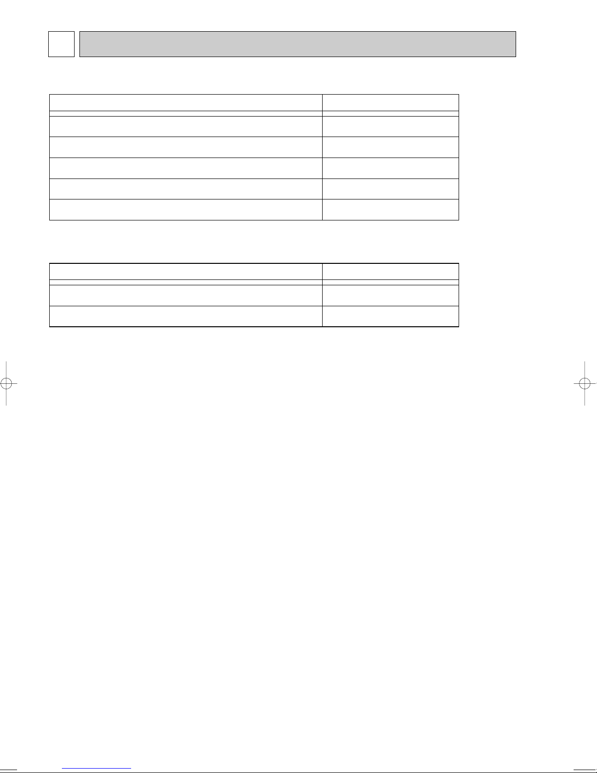
REFERENCE MANUAL
1-1. OUTDOOR UNIT’S SERVICE MANUAL
Service Ref.
PUHZ-RP35/50/60/71/100/125/140VHA
PUHZ-RP100/125/140YHA
PUHZ-RP71/100/125/140VHA-A
PUHZ-RP200/250YHA
PUHZ-RP200/250YHA-A
PU(H)-P·VGAA.UK
PU(H)-P·YGAA.UK
1-2. TECHNICAL DATA BOOK
Service Manual No.
OC334
OC337
OC338
OC339
OC336
2
2 SAFETY PRECAUTION
Do not use the existing refrigerant piping.
The old refrigerant and lubricant in the existing piping
contains a large amount of chlorine which may cause the
lubricant deterioration of the new unit.
Use “low residual oil piping”
If there is a large amount of residual oil (hydraulic oil, etc.)
inside the piping and joints, deterioration of the lubricant
will result.
Use ESTER , ETHER or HAB as the lubricant to
coat flares and flange connection parts.
If large amount of mineral oil enter, that can cause
deterioration of refrigerant oil etc.
Use liquid refrigerant to seal the system.
If gas refrigerant is used to seal the system, the composition
of the refrigerant in the cylinder will change and performance
may drop.
Do not use a refrigerant other than R407C.
If another refrigerant (R22, etc.) is used, the chlorine in the
refrigerant may cause the lubricant deterioration.
Use a vacuum pump with a reverse flow check valve.
The vacuum pump oil may flow back into the refrigerant
cycle and cause the lubricant deterioration.
Store the piping to be used during installation
indoors with keep both ends sealed until just
before brazing.
(Store elbows and other joints in a plastic bag.)
If dust, dirt, or water enters the refrigerant cycle,
deterioration of the oil and compressor trouble may result.
Ventilate the room if refrigerant leaks during
operation. If refrigerant comes into contact with
a flame, poisonous gases will be released.
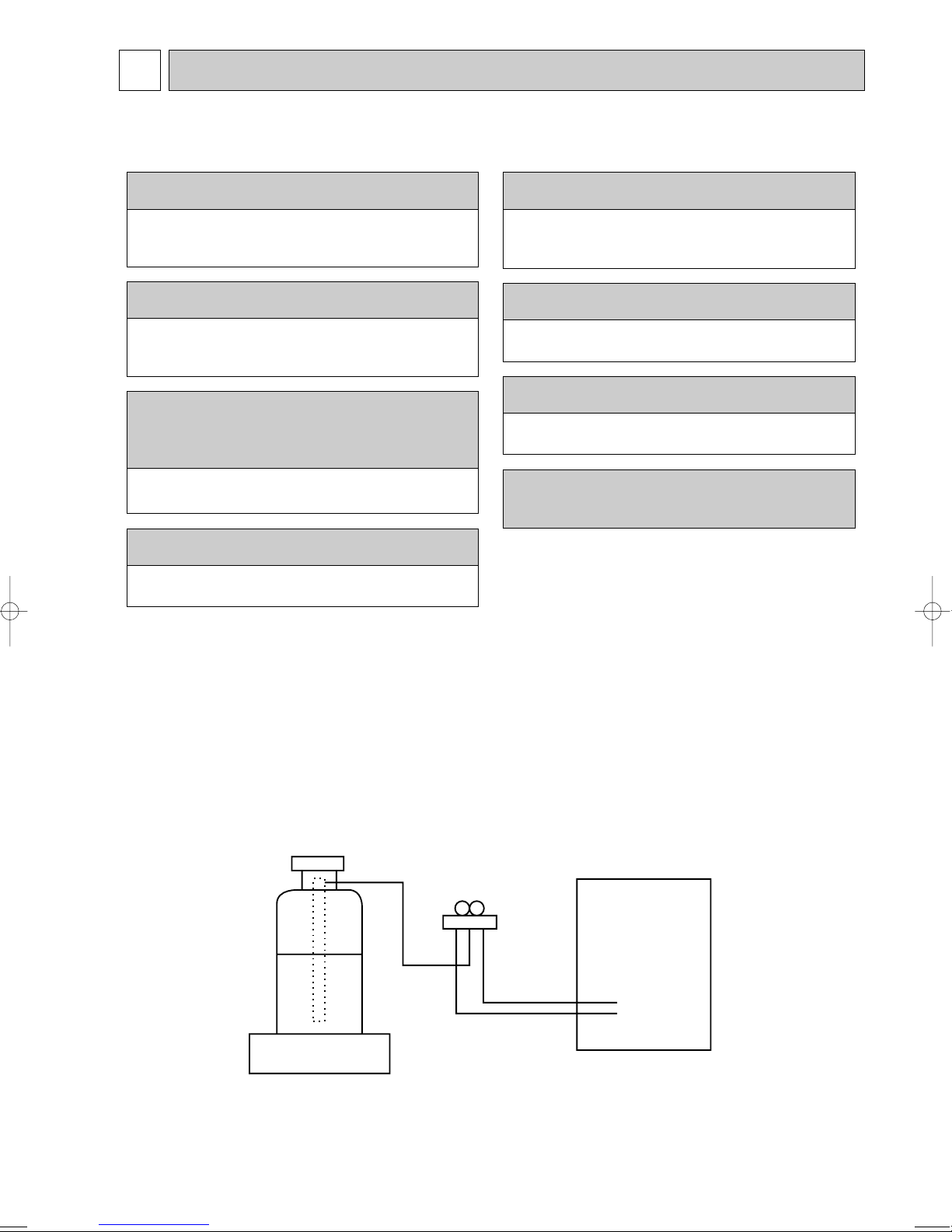
Gravimeter
Unit
CAUTIONS RELATED TO NEW REFRIGERANT
Cautions for units utilizing refrigerant R407C
[1] Cautions for service
·After recovering the all refrigerant in the unit, proceed to working.
·Do not release refrigerant in the air.
·After completing the repair service, recharge the cycle with the specified amount of
liquid refrigerant.
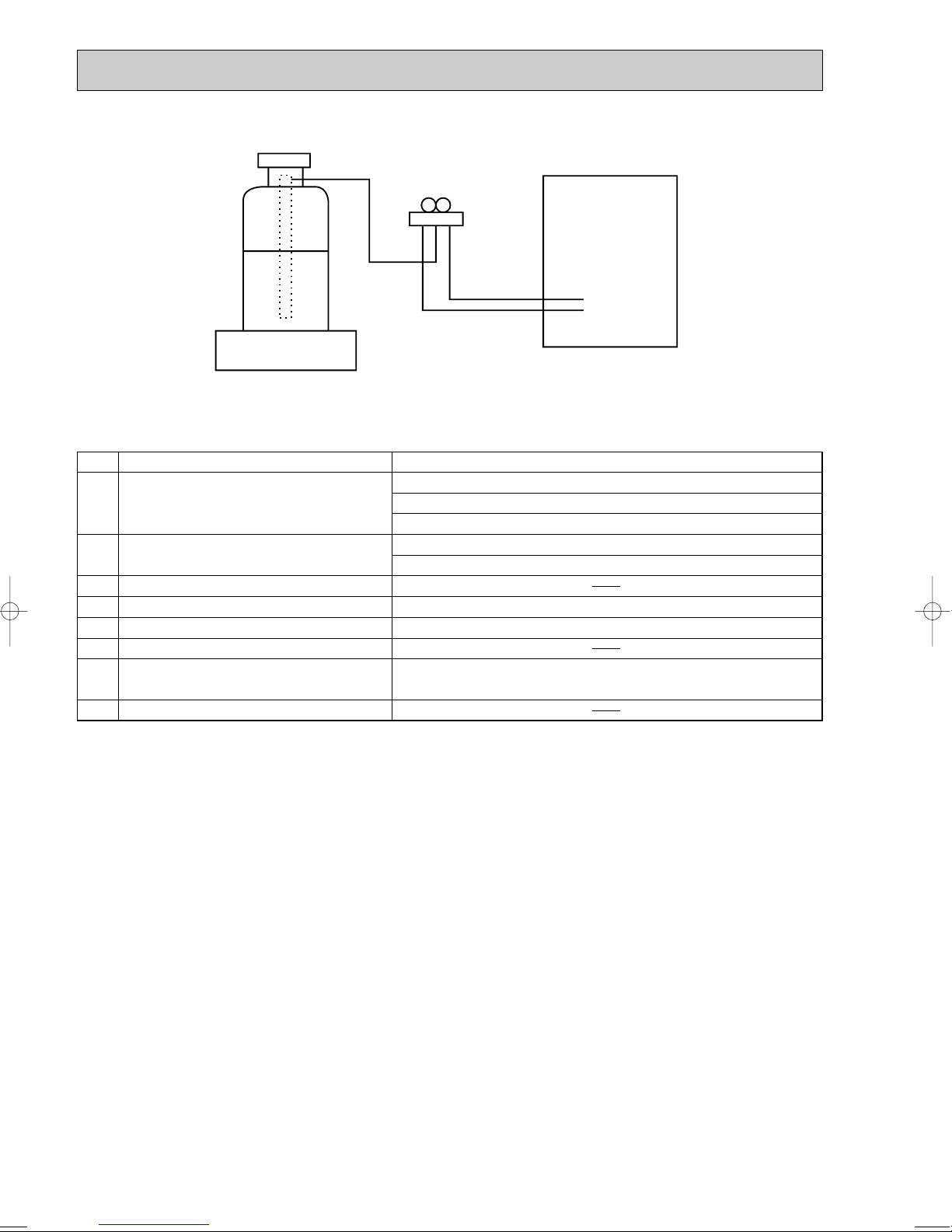
[2] Refrigerant recharging
(1) Refrigerant recharging process
1Direct charging from the cylinder.
·R407C cylinder are available on the market has a syphon pipe.
·Leave the syphon pipe cylinder standing and recharge it.
(By liquid refrigerant)
(2) Recharge in refrigerant leakage case
·After recovering the all refrigerant in the unit, proceed to working.
·Do not release the refrigerant in the air.
·After completing the repair service, recharge the cycle with the specified amount of
liquid refrigerant.
3
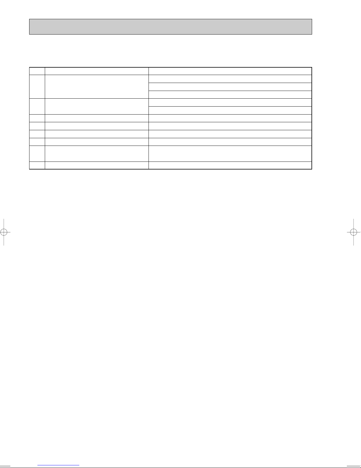
[3] Service tools
Use the below service tools as exclusive tools for R407C refrigerant.
No. Tool name Specifications
1 Gauge manifold ·Only for R407C.
·Use the existing fitting SPECIFICATIONS. (UNF7/16)
·Use high-tension side pressure of 3.43MPa·G or over.
2 Charge hose ·Only for R407C.
·Use pressure performance of 5.10MPa·G or over.
3 Electronic scale
4 Gas leak detector ·Use the detector for R134a or R407C.
5 Adapter for reverse flow check. ·Attach on vacuum pump.
6 Refrigerant charge base.
7 Refrigerant cylinder. ·For R407C ·Top of cylinder (Brown)
·Cylinder with syphon
8 Refrigerant recovery equipment.
4
CAUTIONS RELATED TO NEW REFRIGERANT
Use new refrigerant pipes.
Make sure that the inside and outside of refrigerant piping is clean and it has no contamination
such as sulfur hazardous for use, oxides, dirt,
shaving particles, etc.
In addition, use pipes with specified thickness.
Store the piping to be used during installation
indoors and keep both ends of the piping sealed
until just before brazing. (Leave elbow joints, etc.
in their packaging.)
Use ester oil, ether oil or alkylbenzene oil (small
amount) as the refrigerant oil applied to flares
and flange connections.
In case of using the existing pipes for R22, be careful with
the followings.
· Change flare nut to the one provided with this product.
Use a newly flared pipe.
· Avoid using thin pipes.
Charge refrigerant from liquid phase of gas
cylinder.
If the refrigerant is charged from gas phase, composition
change may occur in refrigerant and the efficiency will be
lowered.
Do not use refrigerant other than R410A.
If other refrigerant (R22 etc.) is used, chlorine in refrigerant can cause deterioration of refrigerant oil etc.
Use a vacuum pump with a reverse flow check
valve.
Vacuum pump oil may flow back into refrigerant cycle and
that can cause deterioration of refrigerant oil etc.
Use the following tools specifically designed for
use with R410A refrigerant.
The following tools are necessary to use R410A refrigerant.
Keep the tools with care.
If dirt, dust or moisture enter into refrigerant cycle, that can
cause deterioration of refrigerant oil or malfunction of compressor.
Do not use a charging cylinder.
If a charging cylinder is used, the composition of refrigerant will change and the efficiency will be lowered.
Flare tool
Electronic refrigerant
charging scale
Vacuum pump adaptor
Size adjustment gauge
Gauge manifold
Torque wrench
Gas leak detector
Charge hose
Tools for R410A
Contamination inside refrigerant piping can cause deterioration of refrigerant oil etc.
If dirt, dust or moisture enter into refrigerant cycle, that can
cause deterioration of refrigerant oil or malfunction of compressor.
If large amount of mineral oil enter, that can cause deterioration of refrigerant oil etc.
Ventilate the room if refrigerant leaks during
operation. If refrigerant comes into contact with
a flame, poisonous gases will be released.
Cautions for units utilizing refrigerant R410A
[1] Cautions for service
(1) Perform service after collecting the refrigerant left in unit completely.
(2) Do not release refrigerant in the air.
(3) After completing service, charge the cycle with specified amount of refrigerant.
(4) When performing service, install a filter drier simultaneously.
Be sure to use a filter drier for new refrigerant.
[2] Additional refrigerant charge
When charging directly from cylinder
· Check that cylinder for R410A on the market is syphon type.
· Charging should be performed with the cylinder of syphon stood vertically. (Refrigerant is charged from liquid phase.)
5
Unit
Gravimeter
[3] Service tools
Use the below service tools as exclusive tools for R410A refrigerant.
No. Specifications
1 Gauge manifold ·Only for R410A
·Use the existing fitting
·Use high-tension side pressure of 5.3MPa·G or over.
2 Charge hose ·Only for R410A
·Use pressure performance of 5.09MPa·G or over.
3 Electronic scale
4 Gas leak detector ·Use the detector for R134a, R407C or R410A.
5 Adaptor for reverse flow check ·Attach on vacuum pump.
6 Refrigerant charge base
7 Refrigerant cylinder ·Only for R410A Top of cylinder (Pink)
8 Refrigerant recovery equipment
specifications
Cylinder with syphon
. (UNF1/2)
6
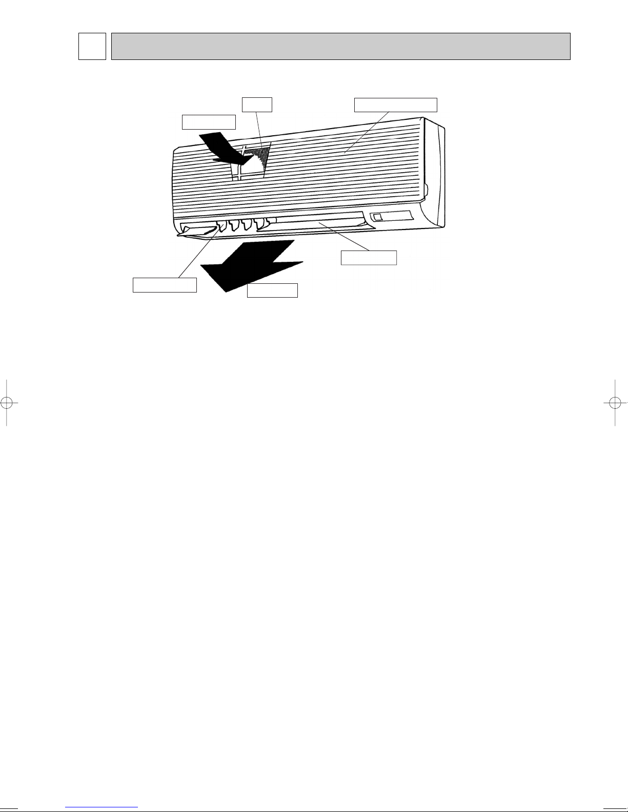
3 PART NAMES AND FUNCTIONS
● Indoor Unit
Air intake
Guide vane
Filter
Air outlet
Air intake grille
Auto vane
7
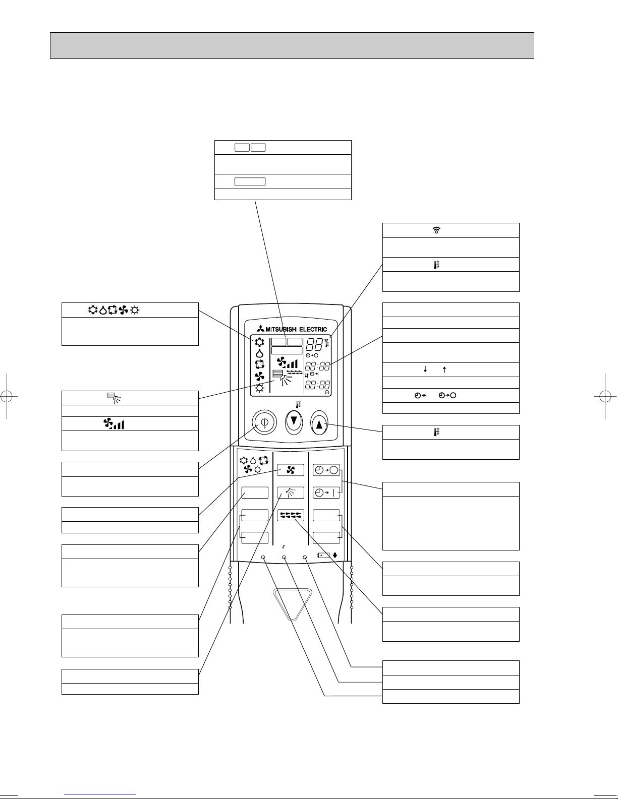
●Wireless remote controller
ON/OFF TEMP
FAN
VANE
TEST RUN
AUTO STOP
AUTO START
h
min
LOUVER
MODE
CHECK
RESETSET CLOCK
MODEL SELECT
NOT AVAILABLE
CHECK
TEST RUN
˚C
AMPM
AMPM
VANE CONTROL button
Used to change the air flow direction.
CLOCK button
RESET button
SET button
ON/OFF button
The unit is turned ON and OFF alternately
each time the button is pressed.
LOUVER button
This switch the horizontal fan motion ON
and OFF.
(Not available for this model.)
MODE SELECT button
Used to switch the operation mode between
cooling, drying, blowing, heating and auto
mode.
CHECK-TEST RUN button
Only press this button to perform an inspection check or test operation.
Do not use it for normal operation.
FAN SPEED SELECT button
Used to change the fan speed.
TIMER display
Displays when in timer operation or when
setting timer.
button
SET TEMPERATURE button sets any desired
room temperature.
CLOCK display
Displays the current time.
“ ” “ ” display
Displays the order of timer operation.
“ ” “ ” display
Displays whether timer is on or off.
w In case the outdoor unit is cool only type,
the heating and auto mode not available.
Buttons used to set the “hour and minute” of
the current time and timer settings.
h and min buttons
display
SET TEMP. display indicates desired temperature set.
display
FAN SPEED display indicates which fan
speed has been selected.
display
The vertical direction of air flow is indicated.
display
Blinks when model is selected.
display
Lights up while transmission to the indoor
unit is mode using switches.
display
CHECK&TEST RUN display indicates that
the unit is being checked or test-run.
display
OPERATION MODE display
Operation mode display indicates which operation mode is in effect.
TIMER CONTROL buttons
AUTO STOP (OFF timer): when this switch
is set, the air conditioner will be automatically stopped at the preset time.
AUTO START (ON timer): when this switch
is set, the air conditioner will be automatically started at the preset time.
MODEL SELECT
CHECK
TEST RUN
● When cover is open.
8

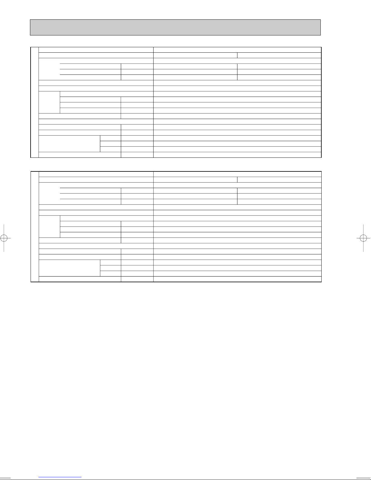
4
kW
A
A
kW
K/min(CFM)
Pa(mmAq)
dB
mm(in.)
mm(in.)
mm(in.)
mm(in.)
kg(lbs)
Service Ref.
Mode
Power supply(phase, cycle, voltage)
Input
Running current
Starting current
External finish
Heat exchanger
Fan Fan(drive) x No.
Fan motor output
Airflow(Low-Medium2-Medium1-High)
External static pressure
Operation control & Thermostat
Noise level(Low-Medium2-Medium1-High)
Unit drain pipe O.D.
Dimensions
Weight
W
D
H
INDOOR UNIT
Cooling
0.07
0.33
0.40
Heating
0.07
0.33
0.40
Single phase, 50Hz, 230V
Munsell 0.70Y 8.59/0.97
Plate fin coil
Line flow (direct) x 1
0.030
9-10-11-12(320-355-390-425)
0(direct blow)
Wireless remote controller & built-in
36-38-41-43
20(13/16)
990(39)
235(9-1/4)
340(13-3/8)
16(35)
PKA-RP50GAL
kW
A
A
kW
K/min(CFM)
Pa(mmAq)
dB
mm(in.)
mm(in.)
mm(in.)
mm(in.)
kg(lbs)
Service Ref.
Mode
Power supply(phase, cycle, voltage)
Input
Running current
Starting current
External finish
Heat exchanger
Fan Fan(drive) x No.
Fan motor output
Airflow(Low-Medium2-Medium1-High)
External static pressure
Operation control & Thermostat
Noise level(Low-Medium2-Medium1-High)
Unit drain pipe O.D.
Dimensions
Weight
W
D
H
INDOOR UNIT
PKA-RP35GAL
Cooling
0.07
0.33
0.40
Heating
0.07
0.33
0.40
Single phase, 50Hz, 230V
Munsell 0.70Y 8.59/0.97
Plate fin coil
Line flow (direct) x 1
0.030
9-10-11-12(320-355-390-425)
0(direct blow)
Wireless remote controller & built-in
36-38-41-43
20(13/16)
990(39)
235(9-1/4)
340(13-3/8)
16(35)
SPECIFICATIONS
9
Service Ref.
Mode
Power supply(phase, cycle,voltage)
External finish
Heat exchanger
Fan Fan(drive) x No.
INDOOR UNIT
Booster heater w1
Operation control & Thermostat
Noise level(Low-Medium2-Medium1-High)
Unit drain pipe O.D.
Dimensions
Weight
w1 : < > Shows the only booster heater rating.
Input w1
Running current w1
Starting current w1
Fan motor output
Airflow(Low-Medium2-Medium1-High)
External static pressure
W
D
H
kW
A
A
kW
K/min(CFM)
Pa(mmAq)
kW
dB
mm(in.)
mm(in.)
mm(in.)
mm(in.)
kg(lbs)
Cooling
PKH-P35GALH
Single phase, 50Hz, 230V
0.07
0.33
0.40
Munsell 0.70Y8.59/0.97
Plate fin coil
Line flow (direct) x 1
0.030
9-10-11-12(318-353-388-424)
0(direct blow)
<0.73>
Wireless remote controller & built-in
36-38-41-43
20(13/16)
990(39)
235(9-1/4)
340(13-3/8)
17(37)
Heating
0.07<0.73>
0.33<3.17>
0.40<3.17>
Service Ref.
Mode
Power supply(phase, cycle,voltage)
External finish
Heat exchanger
Fan Fan(drive) x No.
INDOOR UNIT
Booster heater w1
Operation control & Thermostat
Noise level(Low-Medium2-Medium1-High)
Unit drain pipe O.D.
Dimensions
Weight
w1 : < > Shows the only booster heater rating.
Input w1
Running current w1
Starting current w1
Fan motor output
Airflow(Low-Medium2-Medium1-High)
External static pressure
W
D
H
kW
A
A
kW
K/min(CFM)
Pa(mmAq)
kW
dB
mm(in.)
mm(in.)
mm(in.)
mm(in.)
kg(lbs)
Cooling
PKH-P50GALH
Single phase, 50Hz, 230V
0.07
0.33
0.40
Munsell 0.70Y 8.59/0.97
Plate fin coil
Line flow (direct) x 1
0.030
9-10-11-12(318-353-388-424)
0(direct blow)
<0.73>
Wireless remote controller & built-in
36-38-41-43
20(13/16)
990(39)
235(9-1/4)
340(13-3/8)
17(37)
Heating
0.07<0.73>
0.33<3.17>
0.40<3.17>
10
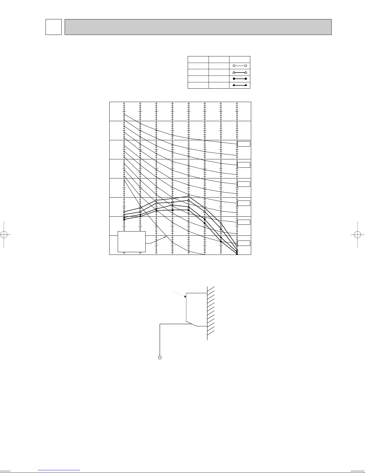
5 NOISE CRITERION CURVES
90
80
70
60
50
40
30
20
10
63 125 250 500 1000 2000 4000 8000
APPROXIMATE
TERESHOLD OF
HEARING FOR
CONTINUOUS
NOISE
NC-60
NC-50
NC-40
NC-30
NC-20
NC-70
OCTAVE BAND SOUND PRESSURE LEVEL, dB (0dB=0.0002 µbar)
BAND CENTER FREQUENCIES, Hz
PKA-RP35GAL
PKA-RP50GAL
PKH-P35GALH
PKH-P50GALH
High
NOTCH
Medium1
Medium2
Low
43
SPL(dB)
41
38
36
LINE
UNIT
WALL
1m
1m
MICROPHONE
11
 Loading...