

Mitsubishi PKA-A-HA7, PKA-A12HA7, PKA-A18HA7 Operation Manual
SPLIT-SYSTEM HEAT PUMP
PKA-A·HA7
OPERATION MANUAL
For safe and correct use, please read this operation manual thoroughly before operating the air-conditioner unit.
MANUEL D’UTILISATION
Pour une utilisation correcte sans risques, veuillez lire le manuel d’utilisation en entier avant de vous servir du
climatiseur.
MANUAL DE INSTRUCCIONES
Lea este manual de instrucciones hasta el final antes de poner en marcha la unidad de aire acondicionado para
garantizar un uso seguro y correcto.
FOR USER
POUR L’UTILISATEUR
PARA EL USUARIO
English
Français
Español
Contents
1. Safety Precautions ...............................................................2
2. Parts Names ........................................................................2
3. Operation .............................................................................6
4. Timer ....................................................................................9
5. Emergency Operation for IR wireless remote controller ......9
6. Care and Cleaning ...............................................................9
1. Safety Precautions
► Before installing the unit, make sure you read all the
“Safety Precautions”.
► The “Safety Precautions” provide very important
points regarding safety. Make sure you follow them.
► Please report to or take consent by the supply author-
ity before connection to the system.
Warning:
• The unit must not be installed by the user. Ask the dealer or an
authorized company to install the unit. If the unit is installed improperly, water leakage, electric shock or fire may result.
• Do not stand on, or place any items on the unit.
• Do not splash water over the unit and do not touch the unit with
wet hands. An electric shock may result.
• Do not spray combustible gas close to the unit. Fire may result.
• Do not place a gas heater or any other open-flame appliance
where it will be exposed to the air discharged from the unit. Incomplete combustion may result.
• Do not remove the front panel or the fan guard from the outdoor
unit when it is running.
• When you notice exceptionally abnormal noise or vibration, stop
operation, turn off the power switch, and contact your dealer.
• Never insert fingers, sticks etc. into the intakes or outlets.
• If you detect odd smells, stop using the unit, turn off the power
switch and consult your dealer. Otherwise, a breakdown, electric
shock or fire may result.
7. Trouble Shooting ................................................................10
8. Specifications .....................................................................12
Symbols used in the text
Warning:
Describes precautions that should be observed to prevent danger
of injury or death to the user.
Caution:
Describes precautions that should be observed to prevent damage
to the unit.
Symbols used in the illustrations
: Indicates a part which must be grounded.
• This air conditioner is NOT intended for use by children or infirm
persons without supervision.
• Young children must be supervised to ensure that they do not
play with the air conditioner.
• If the refrigeration gas blows out or leaks, stop the operation of
the air conditioner, thoroughly ventilate the room, and contact
your dealer.
• When installing or relocating, or servicing the air conditioner, use
only the specified refrigerant (R410A) to charge the refrigerant
lines. Do not mix it with any other refrigerant and do not allow
air to remain in the lines. If air is mixed with the refrigerant, then
it can be the cause of abnormal high pressure in the refrigerant
line, and may result in an explosion and other hazards. The use
of any refrigerant other than that specified for the system will
cause mechanical failure or system malfunction or unit breakdown. In the worst case, this could lead to a serious impediment
to securing product safety.
Caution:
• Do not use any sharp object to push the buttons, as this may
damage the remote controller.
• Never block or cover the indoor or outdoor unit’s intakes or outlets.
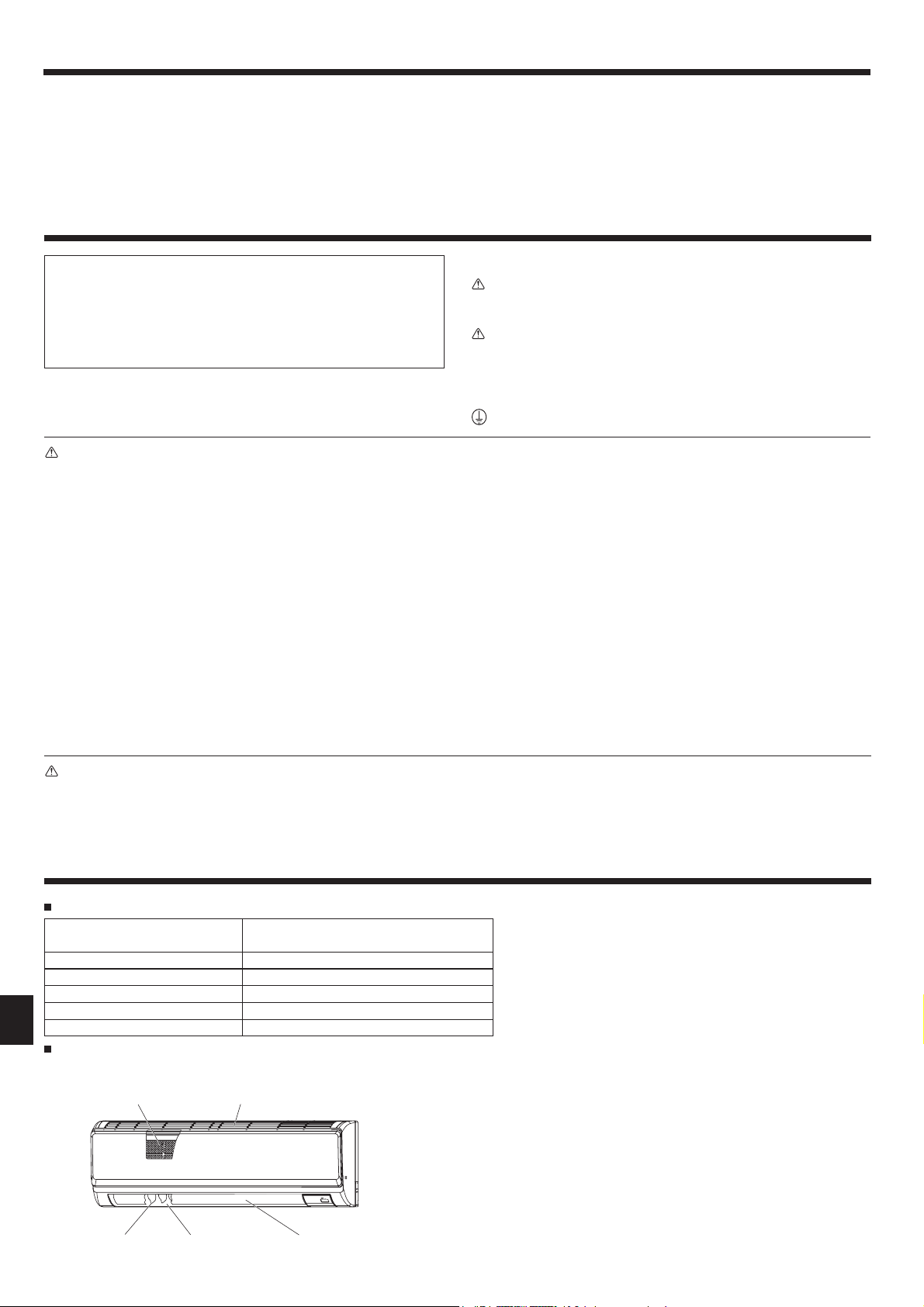
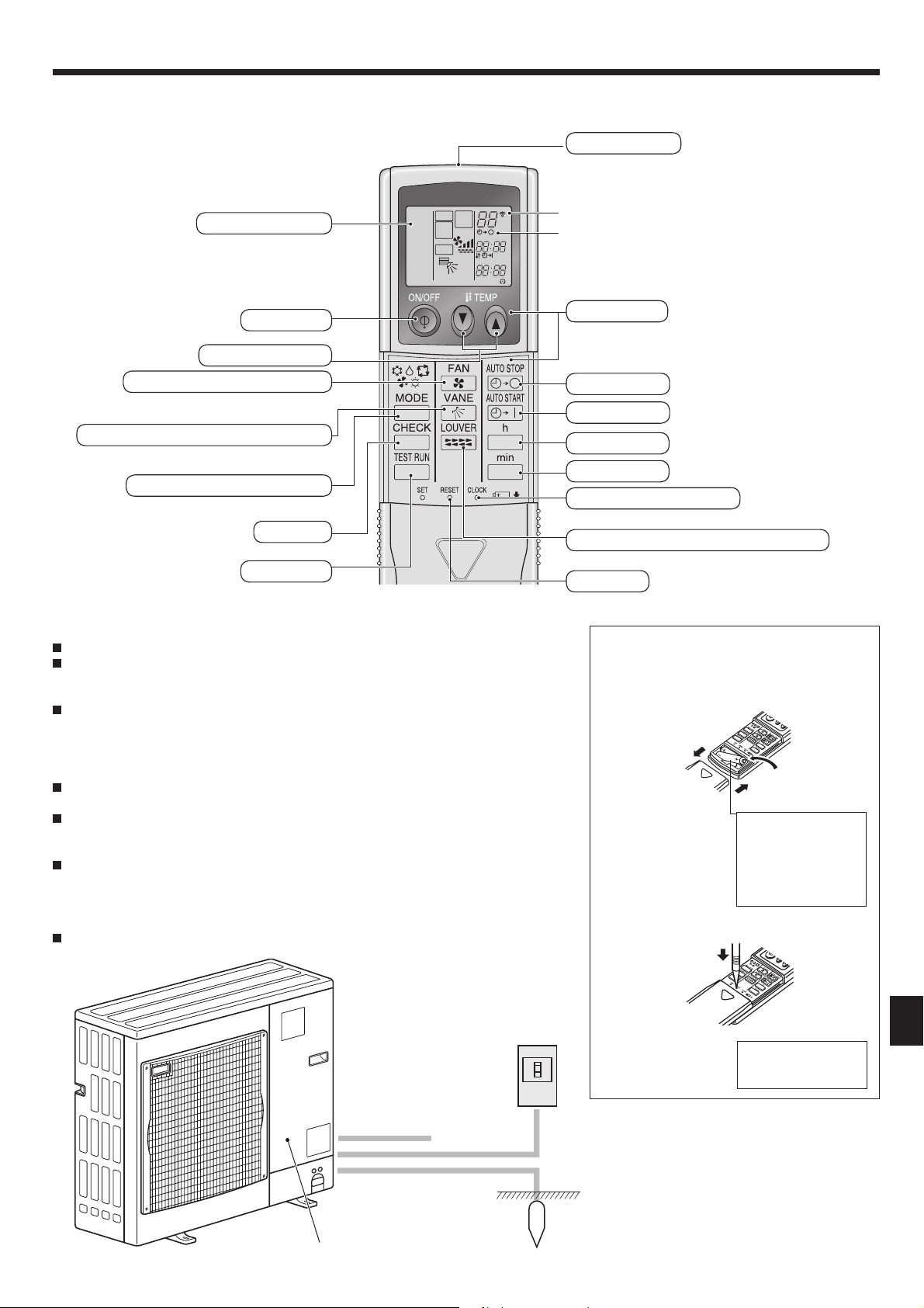
2. Parts Names
Indoor Unit
PKA-A·HA7
Fan speed 3 speeds + Auto
Vane Auto with swing
Louver Manual
Filter Normal
Filter cleaning indication 100 hr
PKA-A·HA7
Wall Mounted
Filter
Air intake
Disposing of the unit
When you need to dispose of the unit, consult your dealer.
Louver
Air outlet
Vane
2
2. Parts Names
Remote controller (Optional parts)
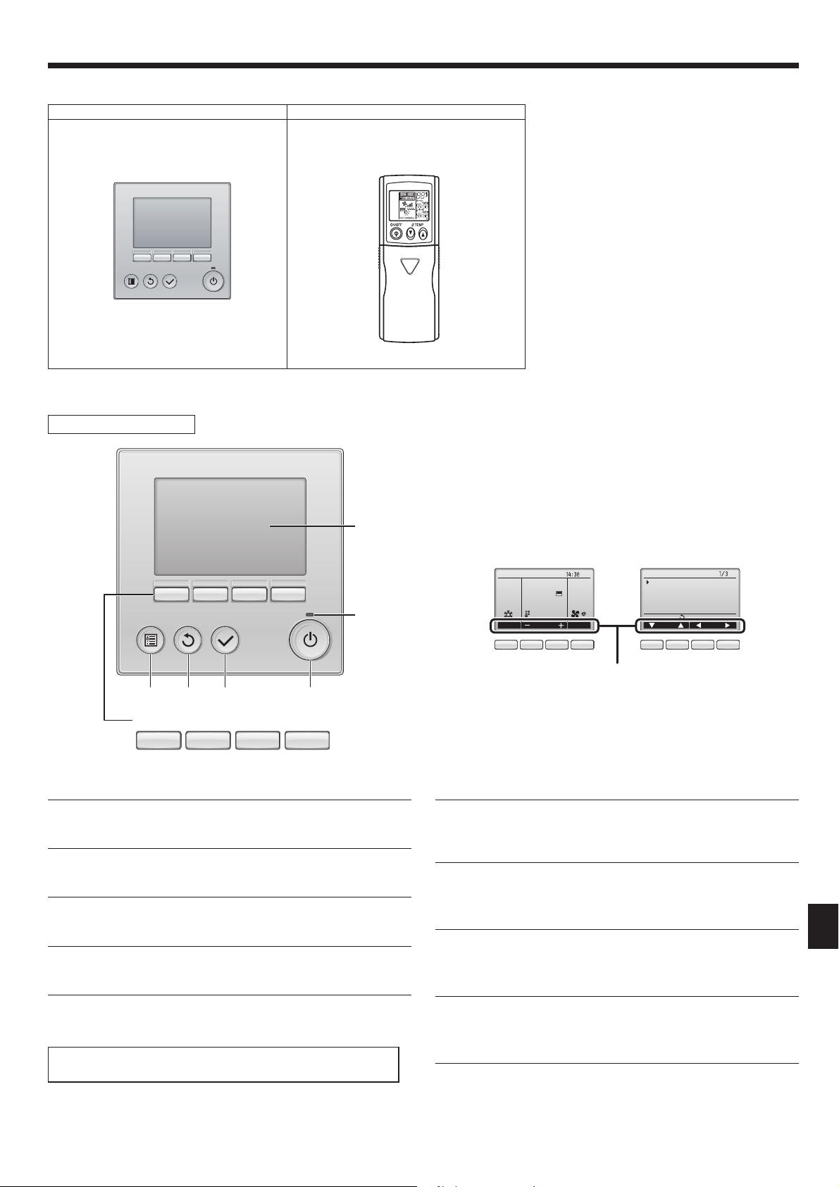
Wired remote controller IR wireless remote controller
TEMP.
■
Wired Remote Controller
Controller interface
ON/OFF
COOL
F
DRY
AUTO
FAN
HEAT
The functions of the function buttons change depending on the
screen.
Refer to the button function guide that appears at the bottom of the
LCD for the functions they serve on a given screen.
When the system is centrally controlled, the button function guide
5
that corresponds to the locked button will not appear.
432 1
Function buttons
789 0
▌1 [ON/OFF] button
Press to turn ON/OFF the indoor unit.
▌2 [SELECT] button
Press to save the setting.
▌3 [RETURN] button
Press to return to the previous screen.
▌4 [MENU] button
Press to bring up the Main menu.
Main display Main menu
Room
Set temp.
6
Cool Auto
83ºF
Mode Temp. Fan
Fri
83ºF
789 0 7
Function guide
Main
Main menu
Vane·Louver·Vent. (Lossnay)
High power
Timer
Weekly timer
OU silent mode
Main display:
Cursor Page
890
▌6 ON/OFF lamp
This lamp lights up in green while the unit is in operation. It blinks while
the remote controller is starting up or when there is an error.
▌7 Function button [F1]
Main display: Press to change the operation mode.
Main menu: Press to move the cursor down.
▌8 Function button [F2]
Main display: Press to decrease temperature.
Main menu: Press to move the cursor up.
▌5 Backlit LCD
Operation settings will appear.
When the backlight is off, pressing any button turns the backlight on
and it will stay lit for a certain period of time depending on the screen.
When the backlight is off, pressing any button turns the backlight on
and does not perform its function. (except for the [ON/OFF] button)
▌9 Function button [F3]
Main display: Press to increase temperature.
Main menu: Press to go to the previous page.
▌0 Function button [F4]
Main display: Press to change the fan speed.
Main menu: Press to go to the next page.
3
2. Parts Names
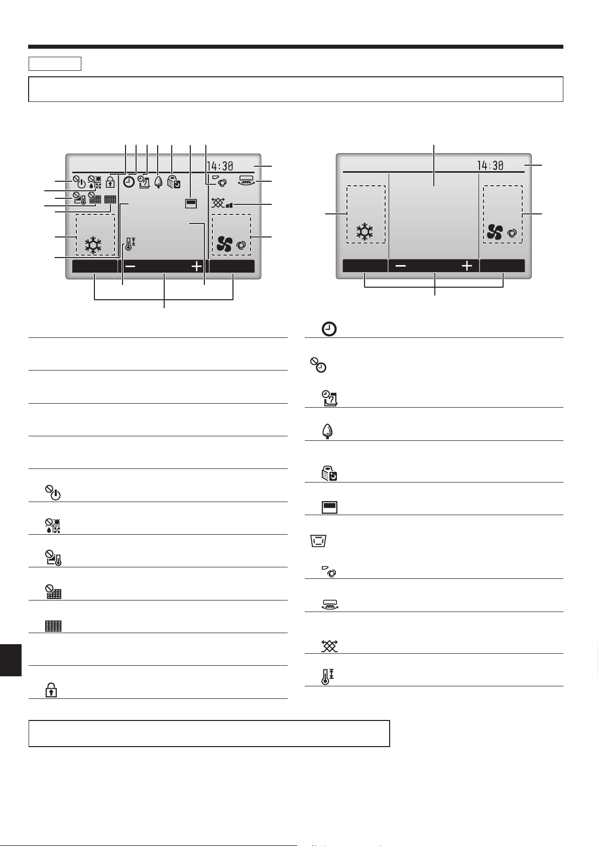
Display
The main display can be displayed in two different modes: “Full” and “Basic”. The factory setting is “Full”. To switch to the “Basic” mode, change the
setting on the Main display setting. (Refer to operation manual included with remote controller.)
<Full mode>
* All icons are displayed for explanation.
2345 6 7 8
6
7
8
9
0
Cool Auto
1
1
Room
83ºF
Set temp.
83ºF
Mode Temp. Fan
!
5
▌1 Operation mode
Indoor unit operation mode appears here.
▌2 Preset temperature
Preset temperature appears here.
▌3 Clock (See the Installation Manual.)
Current time appears here.
<Basic mode>
2
Fri
3
9
)
4
Fri
1
Cool
AutoSet temp.
83ºF
3
4
Mode Temp. Fan
2
5
▌3
Appears when the On/Off timer, Night setback, or Auto-off timer function is enabled.
appears when the timer is disabled by the centralized control
system.
▌4
Appears when the Weekly timer is enabled.
▌4 Fan speed
Fan speed setting appears here.
▌5 Button function guide
Functions of the corresponding buttons appear here.
▌6
Appears when the ON/OFF operation is centrally controlled.
▌7
Appears when the operation mode is centrally controlled.
▌8
Appears when the preset temperature is centrally controlled.
▌9
Appears when the fi lter reset function is centrally controlled.
▌0
Indicates when fi lter needs maintenance.
▌1 Room temperature (See the Installation Manual.)
Current room temperature appears here.
▌2
Appears when the buttons are locked.
▌5
Appears while the units are operated in the energy-save mode. (Will not
appear on some models of indoor units)
▌6
Appears while the outdoor units are operated in the silent mode.
▌7
Appears when the built-in thermistor on the remote controller is activated to monitor the room temperature (1).
appears when the thermistor on the indoor unit is activated to
monitor the room temperature.
▌8
Indicates the vane setting.
▌9
Indicates the louver setting.
(This indication is not available for this model.)
▌)
Indicates the ventilation setting.
▌!
Appears when the preset temperature range is restricted.
Most settings (except ON/OFF, mode, fan speed, temperature) can be made from the Menu screen.
(Refer to operation manual included with remote controller.)
4
2. Parts Names
■
IR Wireless remote controller
Transmission area
Remote controller display
* For explanation purposes, all of the items
that appear in the display are shown.
* All items are displayed when the Reset
button is pressed.
ON/OFF button
Set Temperature buttons
Fan Speed button (Changes fan speed)
Airflow button (Changes up/down airflow direction)
Mode button (Changes operation mode)
Check button
Test Run button
COOL
DRY
AUTO
FA N
HEAT
MODEL
SELECT
FA N
NOT AVAILABLE
RUN
SWING
START
°F
°C
AMPMSTOP
AMPM
TEST
CHECK
Note: (Only for IR wireless remote controller)
When using the IR wireless remote controller, point it towards the receiver on the indoor unit.
If the IR wireless remote controller is operated within approximately 2 minutes after power is
supplied to the indoor unit, the indoor unit may beep twice as the unit is performing the initial
automatic check.
The indoor unit beeps to confirm that the signal transmitted from the IR wireless remote con-
troller has been received. Signals can be received up to approximately 7 meters, 275-19/32
inch in a direct line from the indoor unit in an area 45° to the left and right of the unit. However, illumination such as fluorescent lights and strong light can affect the ability of the indoor unit to receive signals.
If the operation lamp near the receiver on the indoor unit is blinking, the unit needs to be in-
spected. Consult your dealer for service.
Handle the IR wireless remote controller carefully! Do not drop the IR wireless remote con-
troller or subject it to strong shocks. In addition, do not get the IR wireless remote controller
wet or leave it in a location with high humidity.
To avoid misplacing the IR wireless remote controller, install the holder included with the IR
wireless remote controller on a wall and be sure to always place the IR wireless remote controller in the holder after use.
Outdoor unit
Transmission indicator
Timer indicator
Operation areas
Timer Off button
Timer On button
Hour button
Minute button
Set Time button (Sets the time)
Louver button (Changes left/right airflow direction)
Reset button
Battery installation/replacement
1. Remove the top cover, insert 2 AAA batteries,
and then install the top cover.
1
2
Top cover
2. Press the Reset button.
3
2 AAA batteries
Insert the negative (–)
end of each battery
first. Install the batteries in the correct
directions (+, –)!
Service Panel
Power
Press the Reset button with an object that
has a narrow end.
Ref. Pipes
Indoor-Outdoor
Connection wire
Earth
5
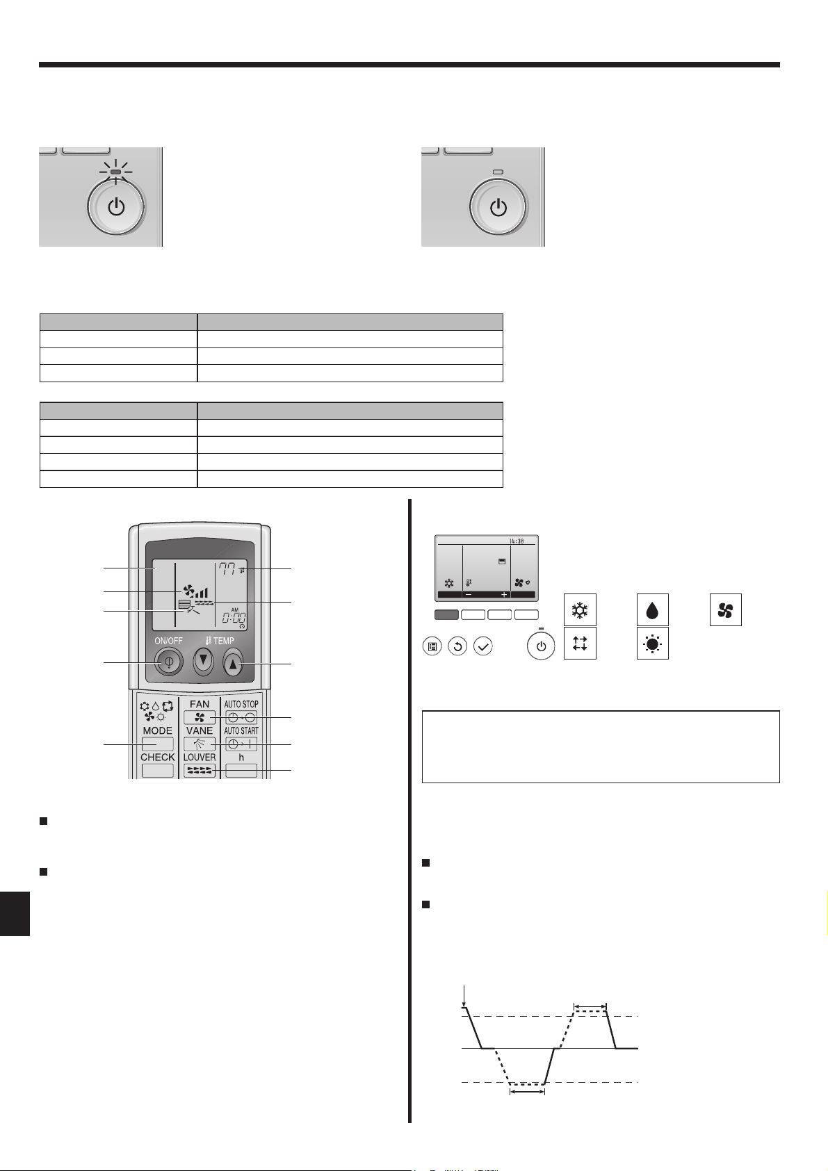
3. Operation
■
About the operation method, refer to the operation manual that comes with each remote controller.
3.1. Turning ON/OFF
<For wired remote controller>
[ON] [OFF]
Press the [ON/OFF] button.
The ON/OFF lamp will light up in
green, and the operation will start.
Note:
Even if you press the ON/OFF button immediately after shutting down the operation is progress, the air conditioner will not start for about 3 minutes.
This is to prevent the internal components from being damaged.
■
Operation status memory
Remote controller setting
Operation mode Operation mode before the power was turned off
Preset temperature Preset temperature before the power was turned off
Fan speed Fan speed before the power was turned off
■
Settable preset temperature range
Operation mode Preset temperature range
Cool/Dry 19 ~ 30 ºC, 67 ~ 87 ºF
Heat 17 ~ 28 ºC, 63 ~ 83 ºF
Auto 19 ~ 28 ºC, 67 ~ 83 ºF
Fan/Ventilation Not settable
Press the [ON/OFF] button again.
The ON/OFF lamp will come off, and
the operation will stop.
<For IR wireless remote controller>
2
COOL
˚F
3
5
6
1
7
3
5
2
6
7
<To Start Operation>
Press the ON/OFF button 1.
• The ON lamp 1 and the display area come on.
<To Stop Operation>
Press the ON/OFF button 1 again.
• The ON lamp 1 and the display area go dark.
Note:
Even if you press the ON/OFF button immediately after shutting down the operation is progress, the air conditioner will not start for about three minutes.
This is to prevent the internal components from being damaged.
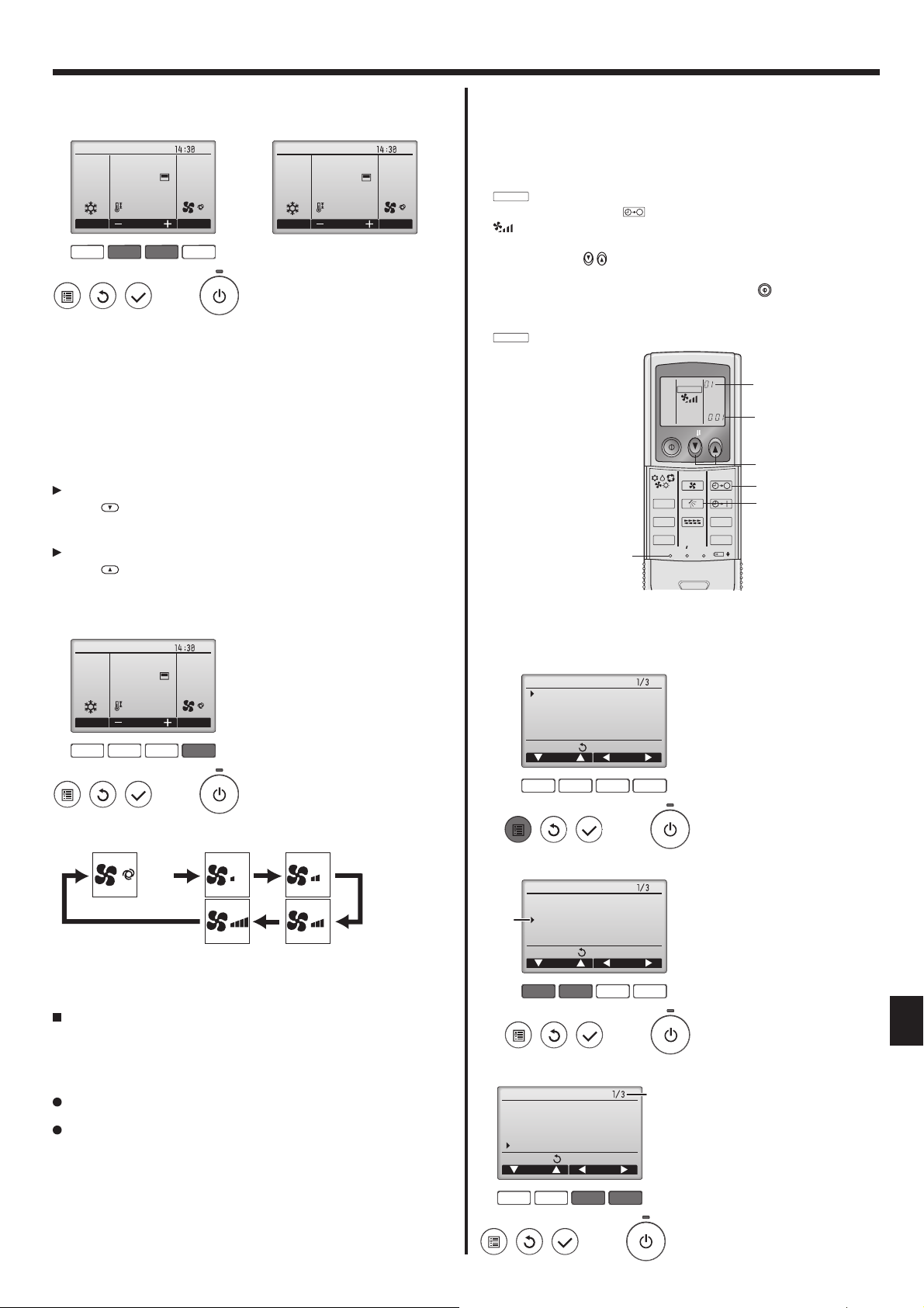
3.2. Operation mode select
Cool/Dry/Fan/Heat/Automatic (cool/heat)/Ventilation modes are available.
Press the [F1] button to go through the op-
Fri
Room
83ºF
Cool
Mode Temp. Fan
F1 F2 F3 F4
AutoSet temp.
83ºF
What the blinking mode icon means
The mode icon will blink when other indoor units in the same refrigerant system (connected to the same outdoor unit) are already operated
in a different mode. In this case, the rest of the unit in the same group
can only be operated in the same mode.
Note:
Heat and Automatic mode can not be available for cooling only units.
Ventilation mode: only indicated on the following condition. Wired remote
controller is used and LOSSNAY is connected.
Automatic mode
According to a set temperature, cooling operation starts if the room
temperature is too hot and heating operation starts if the room temperature is too cold.
During automatic operation, if the room temperature changes and
remains 2 °C, 4 °F or more above the set temperature for 15 minutes,
the air conditioner switches to cooling mode. In the same way, if the
room temperature remains 2 °C, 4 °F or more below the set temperature for 15 minutes, the air conditioner switches to heating mode.
Cooling mode
eration modes in the order of “Cool”, “Dry”,
“Fan”, “Auto”, and “Heat”. Select the desired
operation mode.
Cool Dry Fan
Auto Heat
• Operation modes that are not available
to the connected outdoor unit models will
not appear on the display.
15 minutes (switches
from heating to cooling)
Set temperature +2°C, +4°F
Set temperature
Set temperature -2°C, -4°F
15 minutes (switches
from cooling to heating)
6
3. Operation
3.3. Temperature setting
<For wired remote controller>
<Cool, Dry, Heat, and Auto>
Room
Cool
Mode Temp. Fan
83ºF
AutoSet temp.
83ºF
F1 F2 F3 F4
Fri
Room
Cool
Mode Temp. Fan
(Centigrade in 0.5-degree increments)
84ºF
84ºF
Example display
Fri
AutoSet temp.
Press the [F2] button to decrease the preset temperature, and press the
[F3] button to increase.
• Refer to the table on page 6 for the settable temperature range for different operation modes.
• Preset temperature range cannot be set for Fan/Ventilation operation.
• Preset temperature will be displayed either in Centigrade in 0.5- or
1-degree increments, or in Fahrenheit, depending on the indoor unit
model and the display mode setting on the remote controller.
<For IR wireless remote controller>
To decrease the room temperature:
Press
button 3 to set the desired temperature.
The selected temperature is displayed 3.
To increase the room temperature:
Press button 3 to set the desired temperature.
The selected temperature is displayed
.
3
3.4. Fan speed setting
<For wired remote controller>
Fri
Room
Cool
Mode Temp. Fan
F1 F2 F3 F4
83ºF
83ºF
AutoSet temp.
■ Automatic fan speed setting (For IR wireless remote controller)
It is necessary to set for wireless remote controller only when automatic
fan speed is not set at default setting.
It is not necessary to set for wired remote controller with automatic fan
speed at default setting.
1 Press the SET button with something sharp at the end.
Operate when display of remote controller is off.
MODEL SELECT
blinks and Model No. is lighted A.
2 Press the AUTO STOP button.
blinks and setting No. is lighted B.
(Setting No.01: without automatic fan speed)
3 Press the temp. buttons to set the setting No.02.
(Setting No.02:with automatic fan speed)
If you mistook the operation, press the ON/OFF button and operate
again from procedure 2.
4 Press the SET button with something sharp at the end.
MODEL SELECT
and Model No. are lighted for 3 seconds, then turned off.
MODEL SELECT
B
A
ON/OFF TEMP
3
2
5
h
min
14
MODE
CHECK
TEST RUN
FAN
VANE
LOUVER
RESETSET CLOCK
AUTO STOP
AUTO START
3.5. Airfl ow up/down direction setting
<For wired remote controller>
3.5.1 Navigating through the Main menu
<Accessing the Main menu>
Main
Main menu
Vane·Louver·Vent. (Lossnay)
High power
Timer
Weekly timer
OU silent mode
Main display:
Cursor Page
Press the [MENU] button.
The Main menu will appear.
Press the [F4] button to go through the fan speeds in the following order.
Auto
• The available fan speeds depend on the models of connected indoor
units.
<For IR wireless remote controller>
Press the Fan Speed button as many times as necessary while the
system is running.
• Each press changes the force. The currently selected speed is
shown at display.
Note:
The number of available fan speeds depends on the type of unit
connected.
In the following cases, the actual fan speed generated by the unit
will differ from the speed shown the remote controller display.
1. When the unit is in STANDBY or DEFROST states.
2. When the temperature of the heat exchanger is low in the heat-
ing mode. (e.g. immediately after heating operation starts)
3. In HEAT mode, when room temperature is higher than the tem-
perature setting.
4. When the unit is in DRY mode.
F1 F2 F3 F4
<Item selection>
Main
Main menu
Vane·Louver·Vent. (Lossnay)
Cursor
High power
Timer
Weekly timer
OU silent mode
Main display:
Cursor Page
F1 F2 F3 F4
<Navigating through the pages>
Main
Main menu
Vane·Louver·Vent. (Lossnay)
High power
Timer
Weekly timer
OU silent mode
Main display:
Cursor Page
F1 F2 F3 F4
page
Press [F1] to move the cursor down.
Press [F2] to move the cursor up.
Press [F3] to go to the previous
page.
Press [F4] to go to the next page.
7
3. Operation
<Saving the settings>
OU silent mode
Mon Tue Wed Thu Fri Sat Sun
Start Stop Silent
-
Setting display:
day
F1 F2 F3 F4
<Exiting the Main menu screen>
Fri
Room
Cool
Mode Temp. Fan
83ºF
83ºF
AutoSet temp.
F1 F2 F3 F4
<Display of unsupported functions>
Title
Not available
Unsupported function
Return:
Select the desired item, and press
the [SELECT] button.
The screen to set the selected item
will appear.
Press the [RETURN] button to exit
the Main menu and return to the
Main display.
If no buttons are touched for 10
minutes, the screen will automatically return to the Main display.
Any settings that have not been
saved will be lost.
The message at left will appear if
the user selects a function not supported by the corresponding indoor
unit model.
Fri
Room
Cool
Mode Temp. Fan
83ºF
AutoSet temp.
83ºF
<Vent. setting>
Fri
Low
Vent.
F1 F2 F3 F4
<Returning to the Main menu>
Main
Main menu
Vane·Louver·Vent. (Lossnay)
High power
Timer
Weekly timer
OU silent mode
Main display:
Cursor Page
F1 F2 F3 F4
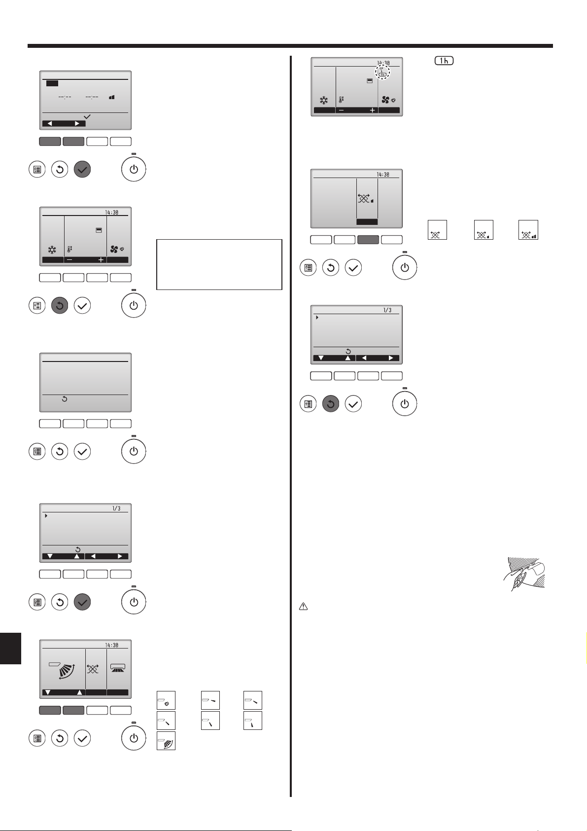
under the vane setting icon
•
This icon will appear when the
vane is set to "Step 2" to "Step 5"
and the fan operates at "Mid 1"
to "Low" speed during cooling or
dry operation (depends on the
model).
The icon will go off in an hour, and
the vane setting will automatically
change.
Press the [F3] button to go through
the ventilation setting options in the
order of "Off", "Low", and "High".
* Settable only when LOSSNAY
unit is connected.
Off Low High
Off Low High
• The fan on some models of indoor units may be interlocked
with certain models of ventilation
units.
Press the [RETURN] button to go
back to the Main menu.
F1 F2 F3 F4
3.5.2 Vane·Vent. (Lossnay)
<Accessing the menu>
Main
Main menu
Vane·Louver·Vent. (Lossnay)
High power
Timer
Weekly timer
OU silent mode
Main display:
Cursor Page
F1 F2 F3 F4
<Vane setting>
Fri
Swing Off Off
LouverVent.Van e
Select "Vane·Louver·Vent. (Lossnay)" from the Main menu (refer to
page 7), and press the [SELECT]
button.
Press the [F1] or [F2] button to go
through the vane setting options:
"Auto", "Step 1", "Step 2", "Step 3",
"Step 4", "Step 5" and "Swing".
Select the desired setting.
Auto
Auto
Step 1 Step 2
Note:
●
During swing operation, the directional indication on the screen
does not change in sync with the directional vanes on the unit.
● Available directions depend on the type of unit connected.
In the following cases, the actual air direction will differ from the
●
direction indicated on the remote controller display.
1. While the display is in “STAND BY” or “DEFROST” states.
2. Immediately after starting heat mode (while the system is wait-
ing for the mode change to take effect).
3. In heat mode, when room temperature is higher than the tem-
perature setting.
<[Manual] To Change the Airfl ow's Left/Right Direction>
* The louver button cannot be used.
• Stop the unit operation, hold the lever of the louver,
and adjust to the desired direction.
* Do not set to the inside direction when the unit is in
the cooling or drying mode because there is a risk
of condensation and water dripping.
Caution:
To prevent falls, maintain a stable footing when operating the unit.
F1 F2 F3 F4
8
Swing
Step 4Step 3
Swing
Step 5
Select "Swing" to move the vanes
up and down automatically.
When set to "Step 1" through "Step
5", the vane will be fixed at the selected angle.
3. Operation
<To Change the Airflow’s Up/Down Direction>
<For IR wireless remote controller>
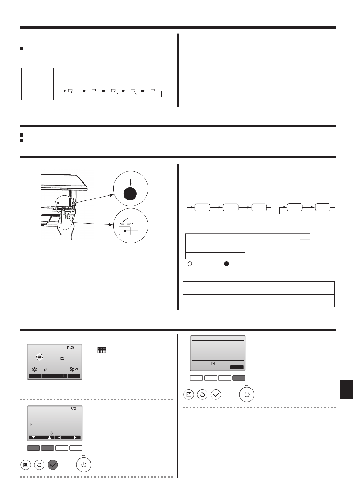
With the unit running, press the Airflow Up/Down button 6 as necessary.
• Each press changes the direction. The current direction is shown at 6.
• The change sequence, and the available settings, are as follows.
Remote controller Display
IR Wireless
remote controller
Swing
1
2
3
4
3.6. Ventilation
► For LOSSNAY combination
The following 2 patterns of operation is available.
• Run the ventilator together with the indoor unit.
• Run
t
Note:
With some model configurations, the fan on the indoor unit may come on
even when you set the ventilator to run independently.
Note: (for IR wireless remote controller and RF thermostat)
Running the ventilator independently is not available.
No indication on the remote controller.
he ventilator independently.
4. Timer
Timer functions are different by each remote controller.
For details on how to operate the remote controller, refer to the appropriate operation manual included with each remote controller.
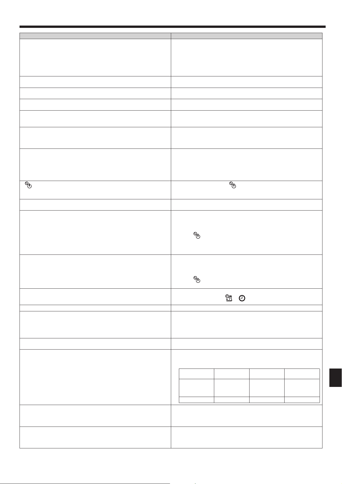
5. Emergency Operation for IR wireless remote controller
(For PKA-A·HA7)
E.O.
SW
• Each press of the emergency operation switch will toggle the operation
mode.
• Check “COOL/HEAT” with the operation monitor display. (The orange
lamp
A follows this monitor display for 5 seconds after pressing the
emergency operation switch.)
[Heat pump type]
Cooling Heating Stop
[Cooling only type]
Cooling Stop
Fig. 5-1
When the IR wireless remote controller cannot be used
When the batteries of the IR wireless remote controller run out or the IR
wireless remote controller malfunctions, the emergency operation can be
done using the emergency buttons.
[Fig. 5-1]
A DEFROST/STAND BY lamp (Orange)
B Operation lamp (Green)
C Emergency operation switch (cooling/heating)
D Receiver
6. Care and Cleaning
■ Filter information
Room
Cool
Mode Temp. Fan
83ºF
AutoSet temp.
83ºF
Fri
will appear on the Main display
in the Full mode when it is time to
clean the filters.
Wash, clean, or replace the filters
when this sign appears.
Refer to the indoor unit Instructions Manual for details.
Operation Monitor Display
GREEN
STOP
COOL
HEAT
ORANGE
○ ○
●○
●
The orange lamp follows the
switch operation as indicated
at the left for 5 seconds, and
then it will return to the normal
display.
●
: Turning off : Lighting
Note:
• Details of emergency mode are as shown below.
Operation mode COOL HEAT
Set temperature 24°C, 75°F 24°C, 75°F
Fan speed High High
Airflow direction Step 1 Step 5
Filter information
Please clean the filter.
Press Reset button after
filter cleaning.
Main menu:
F1 F2 F3 F4
Reset
Press the [F4] button to reset filter
sign.
Refer to the indoor unit Instructions
Manual for how to clean the filter.
Main
Main menu
Restriction
Energy saving
Night setback
Filter information
Error information
Main display:
Cursor Page
F1 F2 F3 F4
Select "Filter information" from the
Main menu (refer to page 7), and
press the [SELECT] button.
9

B
6. Care and Cleaning
Filter information
Reset filter sign?
Cancel
OK
F1 F2 F3 F4
Filter information
Filter sign reset
Main menu:
Room
Cool
Mode Temp. Fan
83ºF
AutoSet temp.
83ºF
Fri
Select "OK" with the [F4] button.
A confirmation screen will appear.
Navigating through the screens
• To go back to the Main menu
....................... [MENU] button
• To return to the previous screen
....................... [RETURN] button
When the is displayed on the
Main display in the Full mode, the
system is centrally controlled and
the filter sign cannot be reset.
Caution:
• Before you start cleaning, stop operation and turn OFF the power
supply.
• Indoor units are equipped with fi lters to remove the dust of suckedin air. Clean the fi lters using the methods shown in the following
sketches.
►
Filter removal
Caution:
• In removing the fi lter, precautions must be taken to protect your
eyes from dust. Also, if you have to climb up on a stool to do the
job, be careful not to fall.
• When the fi lter is removed, do not touch the metallic parts inside
the indoor unit, otherwise injury may result.
PKA-A·HA
7
A
If two or more indoor units are connected, fi lter cleaning timing for
each unit may be different, depending on the fi lter type.
The icon
will appear when the fi lter on the main unit is due for
cleaning.
When the fi lter sign is reset, the cumulative operation time of all units
will be reset.
The icon
is scheduled to appear after a certain duration of
operation, based on the premise that the indoor units are installed in
a space with ordinary air quality. Depending on the air quality, the fi lter
may require more frequent cleaning.
The cumulative time at which fi lter needs cleaning depends on the
model.
• This indication is not available for wireless remote controller.
►
Cleaning the fi lters
• Clean the fi lters using a vacuum cleaner. If you do not have a vacuum
cleaner, tap the fi lters against a solid object to knock off dirt and dust.
• If the fi lters are especially dirty, wash them in lukewarm water. Take
care to rinse off any detergent thoroughly and allow the fi lters to dry
completely before putting them back into the unit.
Caution:
• Do not dry the fi lters in direct sunlight or by using a heat source,
such as an electric heater: this may warp them.
• Do not wash the fi lters in hot water (above 50°C, 122°F), as this
may warp them.
• Make sure that the air fi lters are always installed. Operating the
unit without air fi lters can cause malfunction
7. Trouble Shooting
Using both hands, pull both the bottom corners of the intake grille
1
to open the grille, then lift the fi lter until it clicks at the stop position.
Hold the knobs on the fi lter and pull the fi lter up, then pull it out
2
downward.
(Located in two places, on the left and right.)
Front grille
A
Filter
B
• Wipe the outside of the unit with a clean, dry, soft cloth.
• Clean off any oil stains or fi nger marks using a neutral household detergent (such as dishwashing liquid or laundry detergent).
Caution:
Never use gasoline, benzene, thinner, scouring powder or any type
of non-neutral detergent, as these substances may damage the
unit’s case.
Having trouble? Here is the solution. (Unit is operating normally.)
Air conditioner does not heat or cool well.
When heating operation starts, warm air does not blow from the indoor
unit soon.
During heating mode, the air conditioner stops before the set room temperature is reached.
10
Clean the filter. (Airflow is reduced when the filter is dirty or clogged.)
■
Check the temperature adjustment and adjust the set temperature.
■
Make sure that there is plenty of space around the outdoor unit. Is the
■
indoor unit air intake or outlet blocked?
Has a door or window been left open?
■
Warm air does not blow until the indoor unit has sufficiently warmed
■
up.
When the outdoor temperature is low and the humidity is high, frost
■
may form on the outdoor unit. If this occurs, the outdoor unit performs
a defrosting operation. Normal operation should begin after approximately 10 minutes.
7. Trouble Shooting
Having trouble? Here is the solution. (Unit is operating normally.)
Airflow direction changes during operation or airflow direction cannot be
set.
When the airflow direction is changed, the vanes always move up and
down past the set position before finally stopping at the position.
A flowing water sound or occasional hissing sound is heard.
A cracking or creaking sound is heard.
The room has an unpleasant odor.
A white mist or vapor is emitted from the indoor unit.
Water or vapor is emitted from the outdoor unit.
” appears in the wired remote controller display. (*1)
“
When restarting the air conditioner soon after stopping it, it does not operate even though the ON/OFF button is pressed.
Air conditioner operates without the ON/OFF button being pressed. (*1)■ Is the on timer set?
Air conditioner stops without the ON/OFF button being pressed. (*1)
Wired remote controller timer operation cannot be set. (*1)
“PLEASE WAIT” appears in the wired remote controller display. (*1)
An error code appears in the remote controller display.
Draining water or motor rotation sound is heard.
Noise is louder than specifications.
Nothing appears in the IR wireless remote controller display, the display
is faint, or signals are not received by the indoor unit unless the IR wireless remote controller is close. (*2)
The operation lamp near the receiver for the IR wireless remote controller on the indoor unit is blinking. (*2)
During cooling mode, the vanes automatically move to the horizontal
■
(down) position after 1 hour when the down (horizontal) airflow direction is selected. This is to prevent water from forming and dripping
from the vanes.
During heating mode, the vanes automatically move to the horizontal
■
airflow direction when the airflow temperature is low or during defrosting mode.
When the airflow direction is changed, the vanes move to the set po-
■
sition after detecting the base position.
These sounds can be heard when refrigerant is flowing in the air con-
■
ditioner or when the refrigerant flow is changing.
These sounds can be heard when parts rub against each due to ex-
■
pansion and contraction from temperature changes.
The indoor unit draws in air that contains gases produced from the
■
walls, carpeting, and furniture as well as odors trapped in clothing,
and then blows this air back into the room.
If the indoor temperature and the humidity are high, this condition
■
may occur when operation starts.
During defrosting mode, cool airflow may blow down and appear like
■
a mist.
During cooling mode, water may form and drip from the cool pipes
■
and joints.
During heating mode, water may form and drip from the heat ex-
■
changer.
During defrosting mode, water on the heat exchanger evaporates and
■
water vapor may be emitted.
During central control, “
■
display and air conditioner operation cannot be started or stopped using the wired remote controller.
Wait approximately three minutes.
■
(Operation has stopped to protect the air conditioner.)
Press the ON/OFF button to stop operation.
Is the air conditioner connected to a central wired remote controller?
■
Consult the concerned people who control the air conditioner.
Does “
■
Consult the concerned people who control the air conditioner.
Has the auto recovery feature from power failures been set?
■
Press the ON/OFF button to stop operation.
Is the off timer set?
■
Press the ON/OFF button to restart operation.
Is the air conditioner connected to a central wired remote controller?
■
Consult the concerned people who control the air conditioner.
Does “
■
Consult the concerned people who control the air conditioner.
Are timer settings invalid?
■
If the timer can be set,
ler display.
The initial settings are being performed. Wait approximately 3 minutes.
■
The protection devices have operated to protect the air conditioner.
■
Do not attempt to repair this equipment by yourself.
■
Turn off the power switch immediately and consult your dealer. Be
sure to provide the dealer with the model name and information that
appeared in the remote controller display.
When cooling operation stops, the drain pump operates and then
■
stops. Wait approximately 3 minutes.
The indoor operation sound level is affected by the acoustics of the
■
particular room as shown in the following table and will be higher than
the noise specification, which was measured in an echo-free room.
Location
examples
Noise levels 3 to 7 dB 6 to 10 dB 9 to 13 dB
The batteries are low.
■
Replace the batteries and press the Reset button.
If nothing appears even after the batteries are replaced, make sure
■
that the batteries are installed in the correct directions (+, –).
The self diagnosis function has operated to protect the air conditioner.
■
Do not attempt to repair this equipment by yourself.
■
Turn off the power switch immediately and consult your dealer. Be
sure to provide the dealer with the model name.
” appear in the wired remote controller display?
” appear in the wired remote controller display?
” appears in the wired remote controller
or appears in the wired remote control-
High soundabsorbing rooms
Broadcasting
studio, music
room, etc.
Normal rooms
Reception
room, hotel
lobby, etc.
Low sound-absorbing rooms
Office, hotel
room
11
 Loading...