


Air-Conditioners
PKA-A·GA
PKA-A·GAL
INSTALLATION MANUAL
For safe and correct use, read this manual and the outdoor unit installation manual thoroughly before installing
the air-conditioner unit.
MANUAL DE INSTALACIÓN
Para un uso correcto y seguro, lea detalladamente este manual y el manual de instalación de la unidad exterior
antes de instalar la unidad de aire acondicionado.
FOR INSTALLER
PARA EL INSTALADOR
English
Español
Contents
1. Safety precautions ................................................................................... 2
2. Installation location .................................................................................. 3
3. Installing the indoor unit ........................................................................... 3
4. Installing the refrigerant piping ................................................................. 5
1. Safety precautions
s Before installing the unit, make sure you read all the “Safety precau-
tions”.
s Please report to your supply authority or obtain their consent before
connecting this equipment to the power supply system.
Warning:
Describes precautions that must be observed to prevent danger of injury or
death to the user.
Caution:
Describes precautions that must be observed to prevent damage to the unit.
Warning:
• Ask a dealer or an authorized technician to install the unit.
• For installation work, follow the instructions in the Installation Manual and use
tools and pipe components specifically made for use with refrigerant specified
in the outdoor unit installation manual.
• The unit must be installed according to the instructions in order to minimize
the risk of damage from earthquakes, typhoons, or strong winds. An incorrectly installed unit may fall down and cause damage or injuries.
• The unit must be securely installed on a structure that can sustain its weight.
• If the air conditioner is installed in a small room, measures must be taken to
prevent the refrigerant concentration in the room from exceeding the safety
limit in the event of refrigerant leakage. Should the refrigerant leak and cause
the concentration limit to be exceeded, hazards due to lack of oxygen in the
room may result.
5. Drainage piping work ............................................................................... 6
6. Electrical work .......................................................................................... 7
7. Test run .................................................................................................. 12
8. Easy maintenance function (Option) ...................................................... 15
After installation work has been completed, explain the “Safety precautions,” use, and
maintenance of the unit to the customer according to the information in the Operation
Manual and perform the test run to ensure normal operation. Both the Installation
Manual and Operation Manual must be given to the user for keeping. These manuals
must be passed on to subsequent users.
: Indicates a part which must be grounded.
Warning:
Carefully read the labels affixed to the main unit.
• Ventilate the room if refrigerant leaks during operation. If refrigerant comes
into contact with a flame, poisonous gases will be released.
• All electric work must be performed by a qualified technician according to
local regulations and the instructions given in this manual.
• Use only specified cables for wiring.
• The terminal block cover panel of the unit must be firmly attached.
• Use only accessories authorized by Mitsubishi Electric and ask a dealer or
an authorized technician to install them.
• The user should never attempt to repair the unit or transfer it to another location.
• After installation has been completed, check for refrigerant leaks. If refrigerant leaks into the room and comes into contact with the flame of a heater or
portable cooking range, poisonous gases will be released.
1.1. Before installation (Environment)
Caution:
• Do not use the unit in an unusual environment. If the air conditioner is installed in areas exposed to steam, volatile oil (including machine oil), or sulfuric
gas, areas exposed to high salt content such as the seaside, the performance
can be significantly reduced and the internal parts can be damaged.
• Do not install the unit where combustible gases may leak, be produced, flow,
or accumulate. If combustible gas accumulates around the unit, fire or explosion may result.
• Do not keep food, plants, caged pets, artwork, or precision instruments in the
direct airflow of the indoor unit or too close to the unit as these items can be
damaged by temperature changes or dripping water.
1.2. Before installation or relocation
Caution:
• Be extremely careful when transporting the units. Two or more persons are
needed to handle the unit as it weighs 20 kg, 44 lbs or more. Do not grasp the
packaging bands. Wear protective gloves as you can injure your hands on
the fins or other parts.
• Be sure to safely dispose of the packaging materials. Packaging materials,
such as nails and other metal or wooden parts may cause stabs or other
injuries.
1.3. Before electric work
Caution:
• Be sure to install circuit breakers. If not installed, electric shock may result.
• For the power lines, use standard cables of sufficient capacity. Otherwise, a
short circuit, overheating, or fire may result.
• When installing the power lines, do not apply tension to the cables.
• When the room humidity exceeds 80% or when the drainpipe is clogged, water may drip from the indoor unit. Do not install the indoor unit where such
dripping can cause damage.
• When installing the unit in a hospital or communications office, be prepared
for noise and electronic interference. Inverters, home appliances, high-frequency medical equipment, and radio communications equipment can cause
the air conditioner to malfunction or breakdown. The air conditioner may also
affect medical equipment, disturbing medical care, and communications equipment, harming the screen display quality.
• Thermal insulation of the refrigerant pipe is necessary to prevent condensation. If the refrigerant pipe is not properly insulated, condensation will be formed.
• Place thermal insulation on the pipes to prevent condensation. If the drainpipe is installed incorrectly, water leakage and damage to the ceiling, floor,
furniture, or other possessions may result.
• Do not clean the air conditioner unit with water. Electric shock may result.
• Tighten all flare nuts to specification using a torque wrench. If tightened too
much, the flare nut can break after an extended period.
• Be sure to ground the unit. If the unit is not properly grounded, electric shock
may result.
• Use circuit breakers (ground fault interrupter, isolating switch (+B fuse), and
molded case circuit breaker) with the specified capacity. If the circuit breaker
capacity is larger than the specified capacity, breakdown or fire may result.
1.4. Before starting the test run
Caution:
• Turn on the main power switch more than 12 hours before starting operation.
Starting operation just after turning on the power switch can severely damage the internal parts.
• Before starting operation, check that all panels, guards and other protective
parts are correctly installed. Rotating, hot, or high voltage parts can cause
injuries.
2
• Do not operate the air conditioner without the air filter set in place. If the air
filter is not installed, dust may accumulate and breakdown may result.
• Do not touch any switch with wet hands. Electric shock may result.
• Do not touch the refrigerant pipes with bare hands during operation.
• After stopping operation, be sure to wait at least five minutes before turning off
the main power switch. Otherwise, water leakage or breakdown may result.
2. Installation location
A
C
D
E
B
E
D
C
B
A
F
H
D
W
G H
B
Y
Z
X
3-15/16
W
16-17/32
19-1/2
15-15/16
14-3/16
11-13/16
9-21/32
7-15/32
5-5/16
2-15/16
1-1/4
25/3201-3/8
31/32
3-3/4
8-1/16
10-1/4
12-19/32
13-19/32
19-1/2
5-29/32
9-1/16
8-9/32
5-1/2
6-11/16
7-15/32
16-23/32
1-9/16
0
0
1-3/8
2-5/32
3-5/32
5-1/8
7-15/32
9-1/16
10-23/32
12-7/32
13-3/8
12-11/16
AE
B
C
D
F
G
H
I
J
K
L
M
N
Fig. 2-1
3. Installing the indoor unit
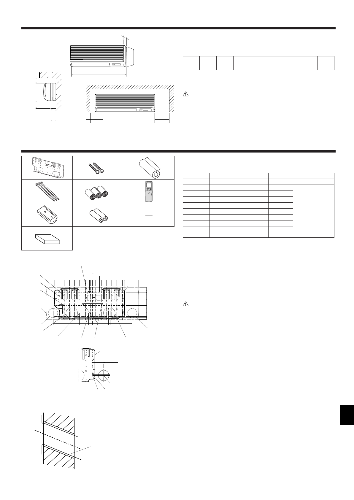
2.1. Outline dimensions (Indoor unit) (Fig. 2-1)
Select a proper position allowing the following clearances for installation and maintenance.
Models W D H AEFGH
A12, A18
990 235 340 Min. 30 Max. 130 Min. 180 Min. 50 Min. 150
39 9-1/4 13-3/8
B Ceiling
C Wall
D Furnishing, etc
Min. 1-13/16 Max. 5 Max. 7-3/32 Min. 1-31/32 Min. 5-29/32
(mm)
(inch)
Warning:
Mount the indoor unit on a ceiling strong enough to withstand the weight of the
unit.
2.2. Outline dimensions (Outdoor unit)
Refer to the outdoor unit installation manual.
1
2
3
3.1. Check the indoor unit accessories (Fig. 3-1)
The indoor unit should be supplied with the following accessories.
PART NUMBER
4
5
6
1 Mount board 1
ACCESSORY QUANTITY
LOCATION OF SETTING
Fix at the back of the unit
2 Tapping screw 4 × 35 12
3 Pipe cover 1
4 Band 3
7
89
0
5 Felt tape 3
6 Wireless remote controller 1
7 Remocon holder 1
8 Alkali batteries (size AAA) 2
9 Mount piece 1
Set inside the unit
for PKA-A·GAL
}
0 Wired remote controller 1 for PKA-A·GA
66
88
6 -
8 are stored in a cut-out section of the packing material (styrofoam).
66
88
Fig. 3-1
(inch)
3.2. Installing the wall mounting fixture (Fig. 3-2)
3.2.1. Setting the wall mounting fixture and piping positions
s Using the wall mounting fixture, determine the unit’s installation position
and the locations of the piping holes to be drilled.
Warning:
Before drilling a hole in the wall, you must consult the building contractor.
A Supporting piece I Bottom left pipe slot knockout hole
B Mount board J Bottom right pipe slot (ø90 mm, 3-9/16 inch)
C Main body K Bottom right pipe slot knockout hole
D Slot (6-11 × 20, L Liquid pipe flare connection position
6P-7/16 × 25/32 inch) M Gas pipe flare connection position
E Unit center N Level setting standard
F Bolt hole (14-ø14 mm, V Insert scale.
14P-9/16 inch) Y Hole centre
G Tapping hole (49-ø5 mm, Z Align the scale with the line.
49P-3/16 inch)
H Bottom left pipe slot
(ø90 mm, 3-9/16 inch)
Fig. 3-2
3.2.2. Drilling the piping hole (Fig. 3-3)
s Use a core drill to make a hole of 90-100 mm, 3-9/16 to 4 inch diameter in the
wall in the piping direction, at the position shown in the diagram to the left.
Fig. 3-3
A Sleeve
B Hole
C (Indoors)
D Wall
E (Outdoors)
s The hole should incline so that the outside opening is lower than the inside
opening.
s Insert a sleeve (with a 90 mm, 3-9/16 inch diameter and purchased locally)
through the hole.
Note:
The purpose of the hole’s inclination is to promote drain flow.
3
3. Installing the indoor unit
1
D
2
B
A
C
A
B
D
C
a
A
b
a
a
A
B
b
b
A
B
C
B
A
A
1-3/16~1-37/64
C
A
B
Fig. 3-4
Fig. 3-5
A Min. 140 mm,
5-1/2 inch
B Min. 300 mm,
11-13/16 inch
C Min. 55 mm,
2-3/16 inch
D Mount board
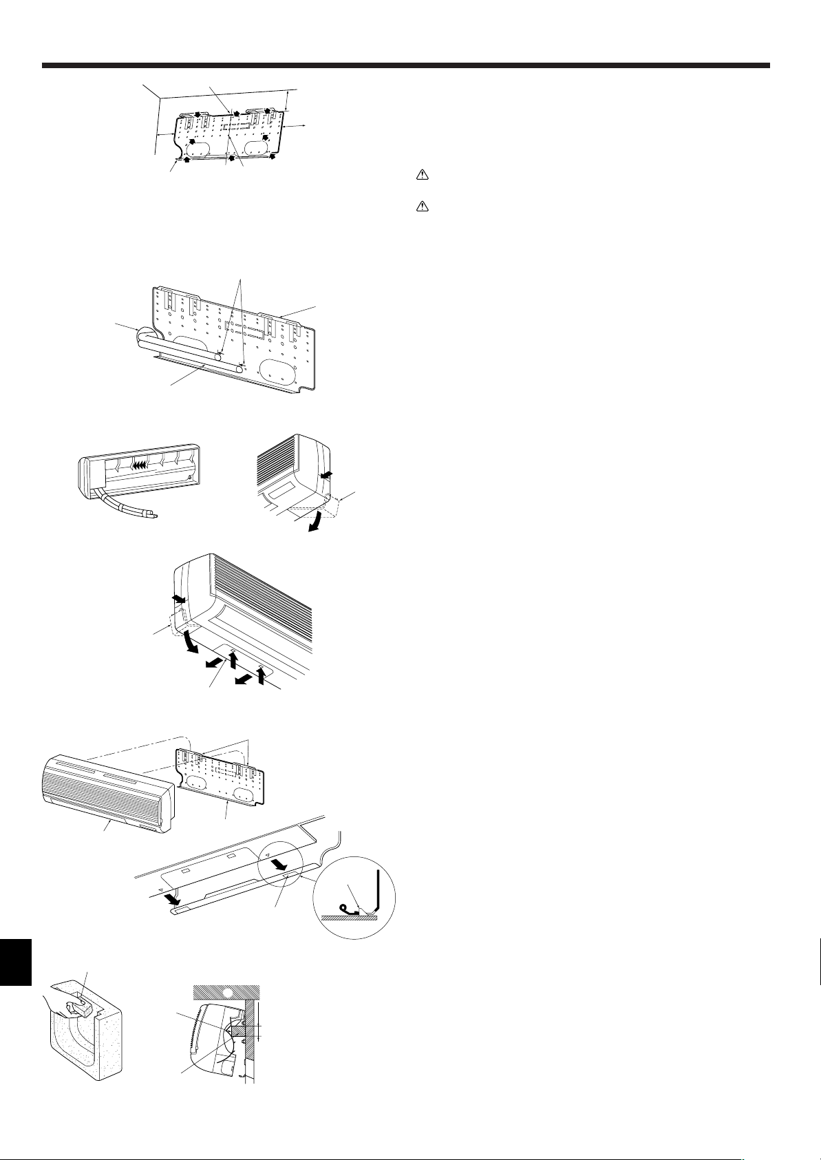
3.2.3. Installing the wall mounting fixture
s Since the indoor unit weighs near 30 kg, 66 lbs selection of the mounting
location requires thorough consideration. If the wall does not seem to be
strong enough, reinforce it with boards or beams before installation.
s The mounting fixture must be secured at both ends and at the centre, if
possible. Never fix it at a single spot or in any nonsymetrical way.
(If possible, secure the fixture at all the positions marked with a bold arrow.)
(Fig. 3-4)
Warning:
If possible, secure the fixture at all positions indicated with a bold arrow.
Caution:
• The unit body must be mounted horizontally.
• Fasten at the holes marked with ▲ as shown by the arrows.
1 Fasten a thread to the hole.
2 The level can be easily obtained by hanging a weight from the string and aligning the string
with the mark.
3.3. When embedding pipes into the wall (Fig. 3-5)
• The pipes are on the bottom left.
• When the cooling pipe, drain pipes internal/external connection lines etc are to be
embedded into the wall in advance, the extruding pipes etc, may have to be bent
and have their length modified to suit the unit.
• Use marking on the mount board as a reference when adjusting the length of the
embedded cooling pipe.
• During construction, give the length of the extruding pipes etc some leeway.
A Mount board
B Reference marking for flare connection
C Through hole
D On-site piping
Fig. 3-6
Fig. 3-7
3.4. Preparing the indoor unit
Rear, right and lower piping (Fig. 3-6)
1. Bind the cooling pipe and drain pipe together.
• Bind the pipes together with vinyl tape at three or more points. This will facilitate
passing the pipes through the wall.
2. Remove the corner box and knock out the knockout holes as necessary.
• Remove the corner box by pushing in a downward direction b, while at the same
time, pressing in the upper side part of the corner box a.
A Corner box
B Under cover
Left and left rear piping (Fig. 3-7)
1. Remove the under cover.
• Remove the under cover by sliding it towards the rear of the unit b, while at the
same time, pressing the two points marked by arrow heads a.
2. Remove the corner box and knock out the knockout holes as necessary.
3.5. Mounting the indoor unit
1. Affix the mounting plate to the wall.
2. Hang the indoor unit on the two hooks positioned on the upper part of the mount-
ing plate.
Rear, right and lower piping (Fig. 3-8)
3. Affix the indoor unit.
4. After connecting the pipes, put the corner box back to where it was (follow the
removal steps backwards).
A Square hole
B Hooks
Fig. 3-8
Left and left rear piping (Fig. 3-9)
(inch)
4
Fig. 3-9
3. Cut out a mounting piece from the packaging material.
4. Pull the indoor unit up towards yourself as shown in the figure below and slide the
mounting piece in to the mounting plate using the mounting piece setting marks
as reference.
5. After connecting the pipes and wiring, put the under cover back to where it was,
and remove the mounting piece and affix the indoor unit as shown in the left
figure.
6. Put the corner box back to where it was.
A Mounting piece
B Ceiling
C Rib
4. Installing the refrigerant piping
90° ±0.5°
øA
R1-64 to R1/32
A
45°±2°
B
C
D
Fig. 4-1
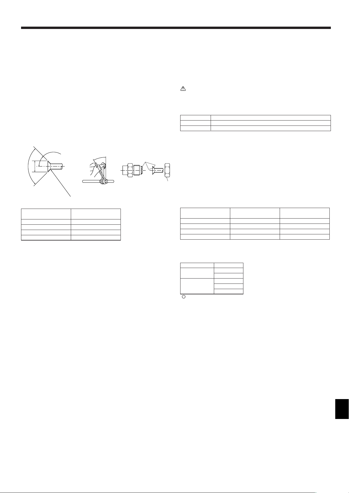
A Flare cutting dimensions
Copper pipe O.D. Flare dimensions
(mm, inch) øA dimensions (mm, inch)
ø6.35, 1/4” 8.7 - 9.1, 11/32-23/64
ø9.52, 3/8” 12.8 - 13.2, 1/2-33/64
ø12.7, 1/2” 16.2 - 16.6, 41/64-21/32
ø15.88, 5/8” 19.3 - 19.7, 49/64-25/32
(inch)
4.1. Precautions
4.1.1. For devices that use R410A refrigerant
• Use ester oil, ether oil, alkylbenzene oil (small amount) as the refrigeration oil
applied to the flared sections.
• Use C1220 copper phosphorus, for copper and copper alloy seamless pipes,
to connect the refrigerant pipes. Use refrigerant pipes with the thicknesses
specified in the table to the below. Make sure the insides of the pipes are
clean and do not contain any harmful contaminants such as sulfuric compounds, oxidants, debris, or dust.
Warning:
When installing or moving the air conditioner, use only the specified refrigerant (R410A) to charge the refrigerant lines. Do not mix it with any other refrigerant and do not allow air to remain in the lines. Air enclosed in the lines can
cause pressure peaks resulting in a rupture and other hazards.
A12, A18
Liquid pipe ø6.35mm, 1/4 inch thickness 0.8 mm, 1/32 inch
Gas pipe ø12.7mm, 1/2 inch thickness 0.8 mm, 1/32 inch
• Do not use pipes thinner than those specified above.
4.2. Connecting pipes (Fig. 4-1)
• When commercially available copper pipes are used, wrap liquid and gas pipes
with commercially available insulation materials (heat-resistant to 100 °C, 212 °F or
more, thickness of 12 mm, 1/2 inch or more).
• The indoor parts of the drain pipe should be wrapped with polyethylene foam insulation materials (specific gravity of 0.03, thickness of 9 mm, 23/64 inch or more).
• Apply thin layer of refrigerant oil to pipe and joint seating surface before tightening
flare nut.
• Use two wrenches to tighten piping connections.
• Use refrigerant piping insulation provided to insulate indoor unit connections. Insu-
late carefully.
B Flare nut tightening torque
Copper pipe O.D. Flare nut O.D. Tightening torque
(mm, inch) (mm, inch) (N·m, ft·lbs)
ø6.35, 1/4” 17, 43/64 14 - 18, 10-13
ø9.52, 3/8” 22, 7/8 34 - 42, 25-30
ø12.7, 1/2” 26, 1-3/64 49 - 61, 35-44
ø15.88, 5/8” 29, 1-9/64 68 - 82, 49-59
C Apply refrigerating machine oil over the entire flare seat surface.
D Use correct flare nuts meeting the pipe size of the outdoor unit.
Available pipe size
A12, A18
Liquid side
Gas side –
: Factory flare nut attachment to the heat-exchanger.
ø6.35
–
ø12.7
–
5
 Loading...